Cisco Systems 102074P Cisco Aironet 802.11n Dual Band Mesh Access Points User Manual 1550 ch2

Cisco Systems Inc Cisco Aironet 802.11n Dual Band Mesh Access Points 1550 ch2

Contents

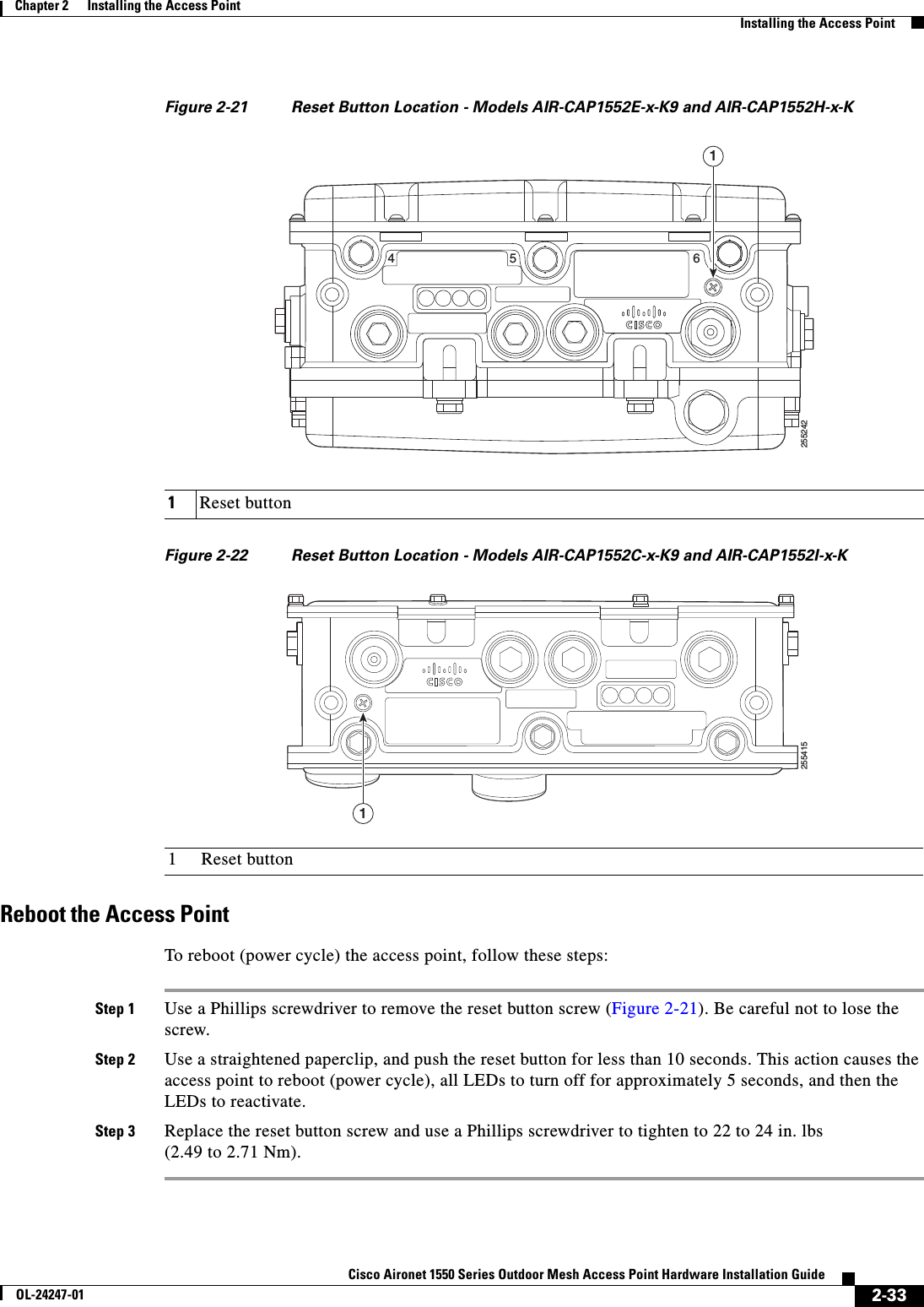
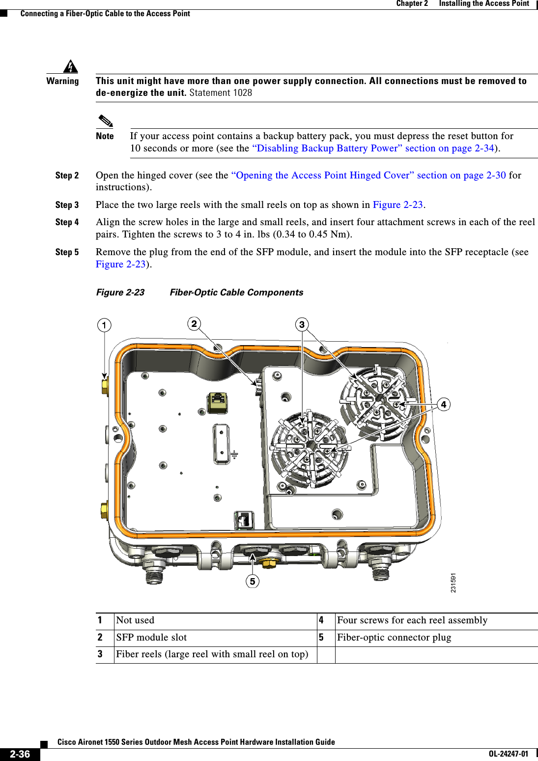
Installation Instructions
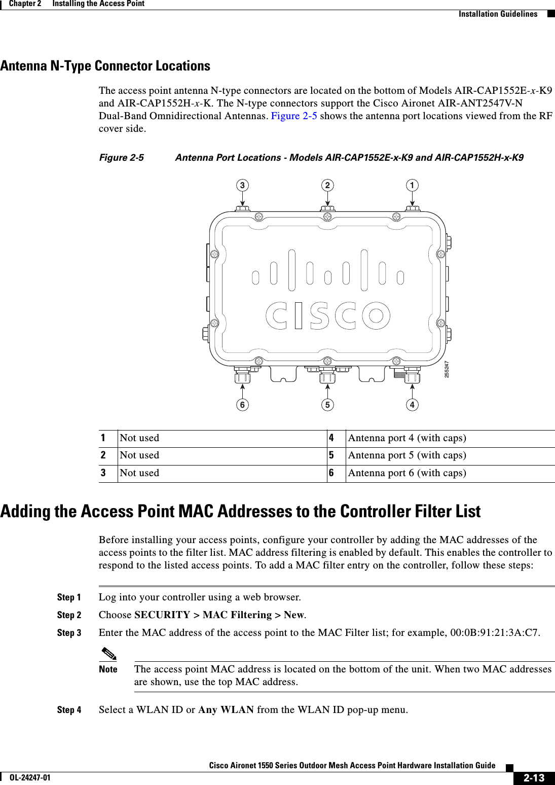
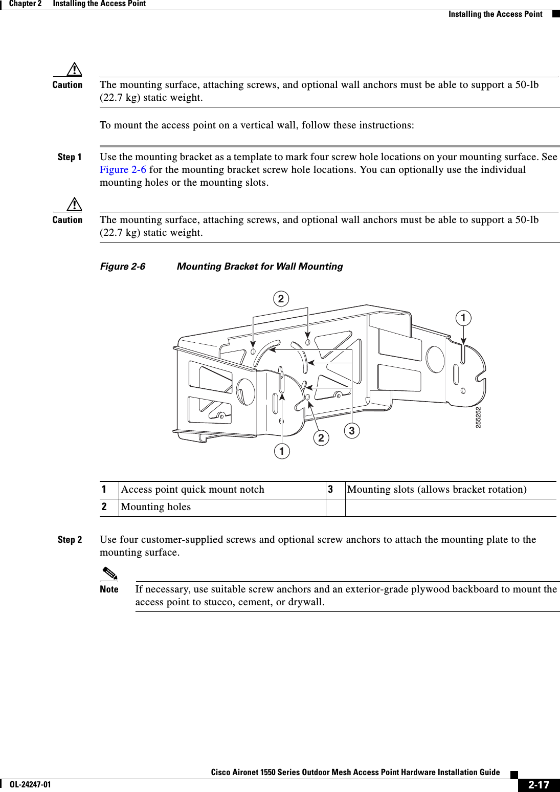
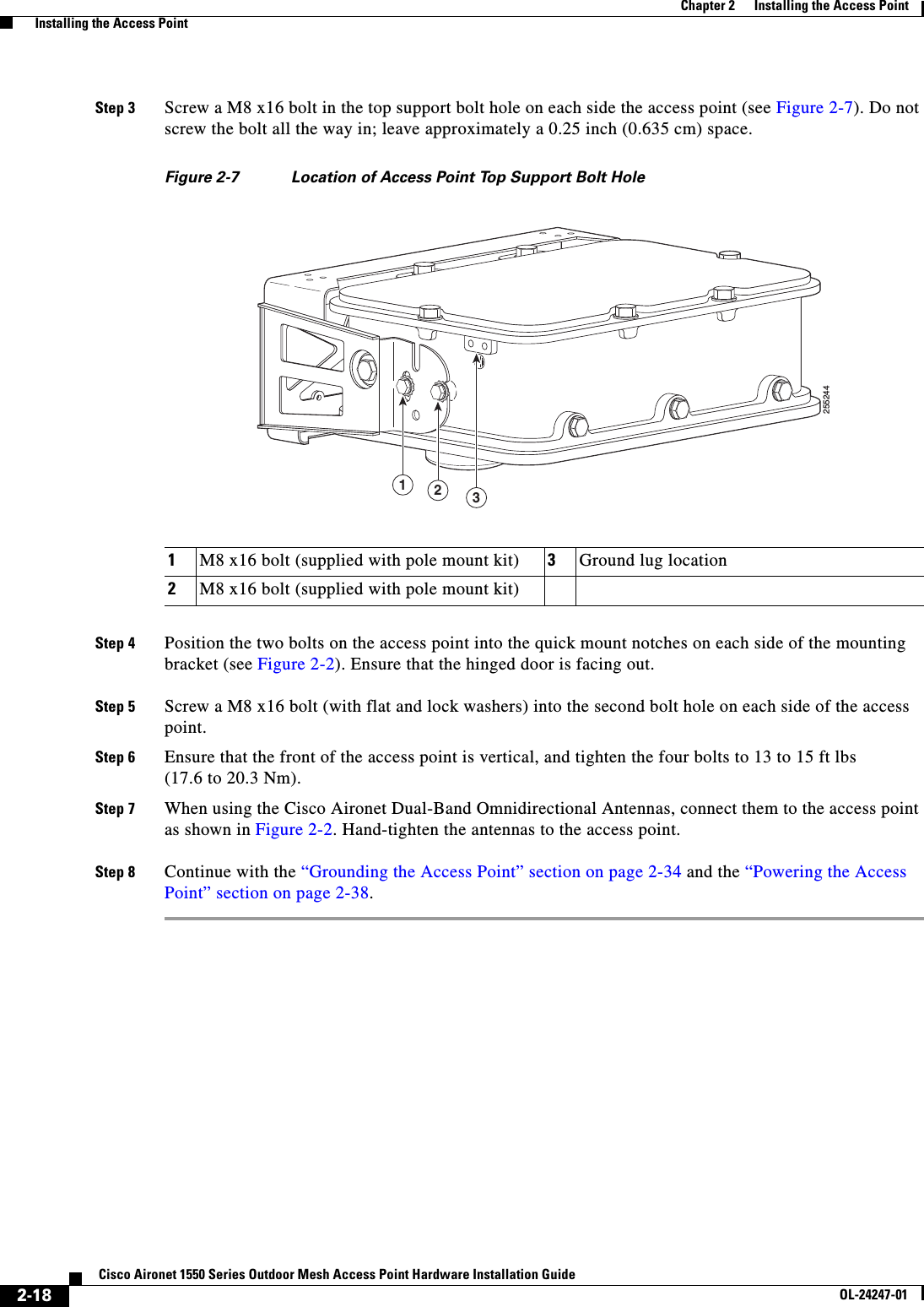
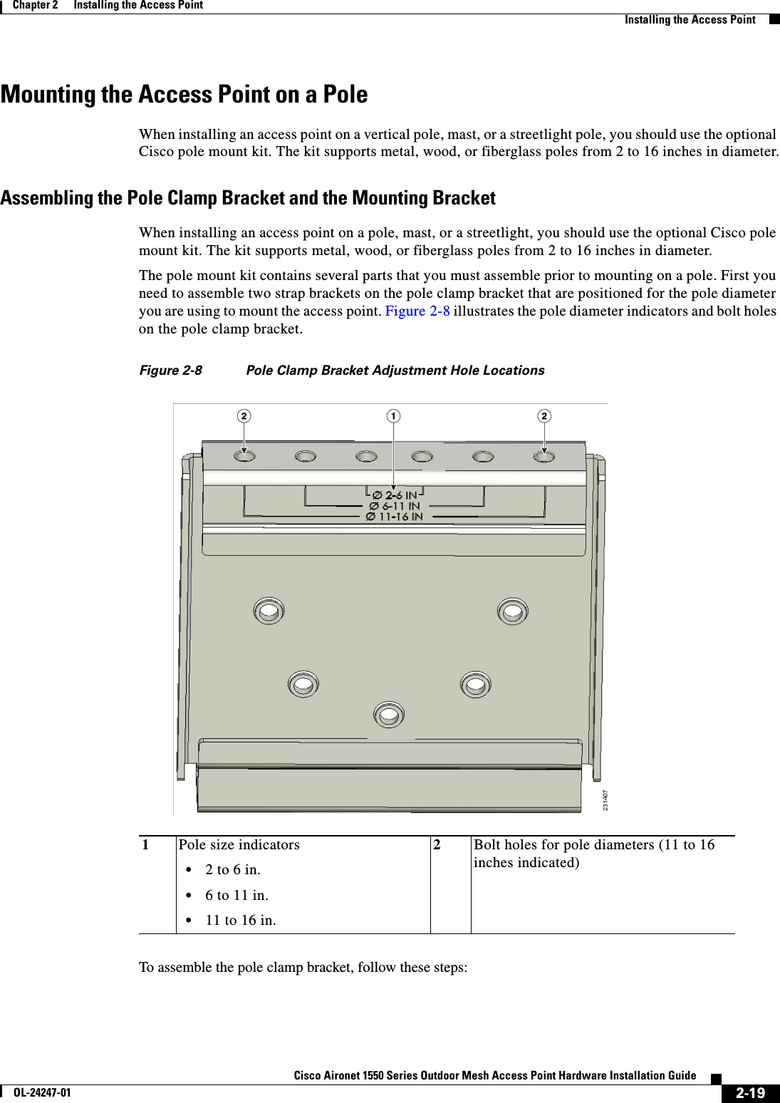
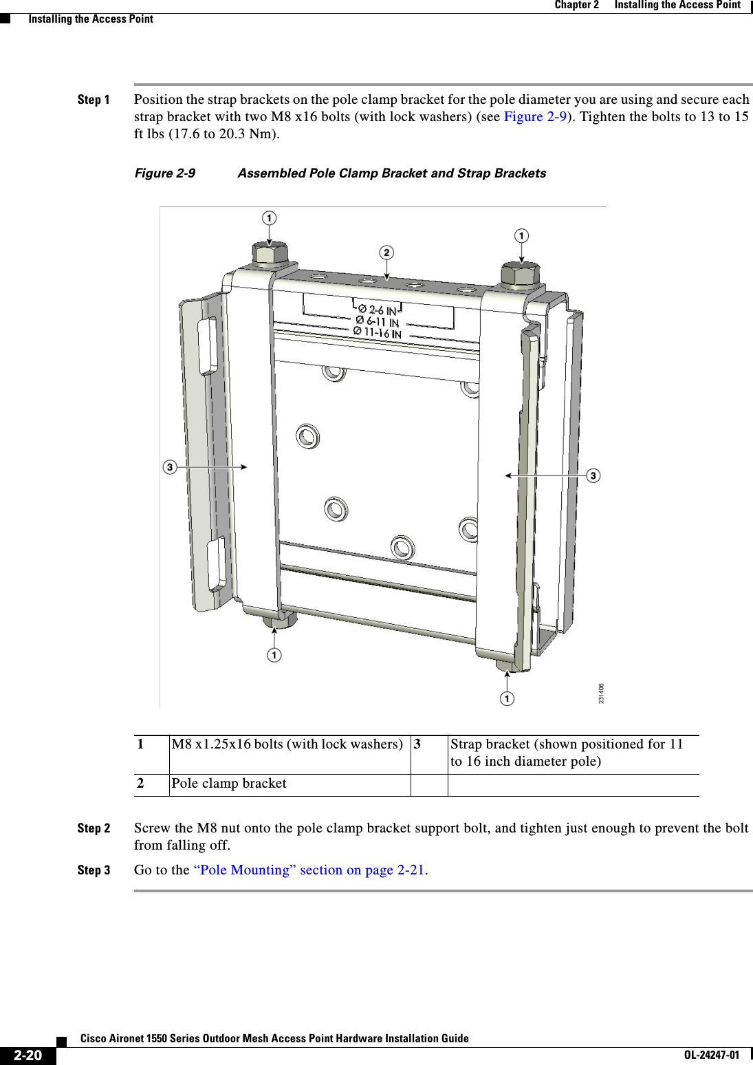
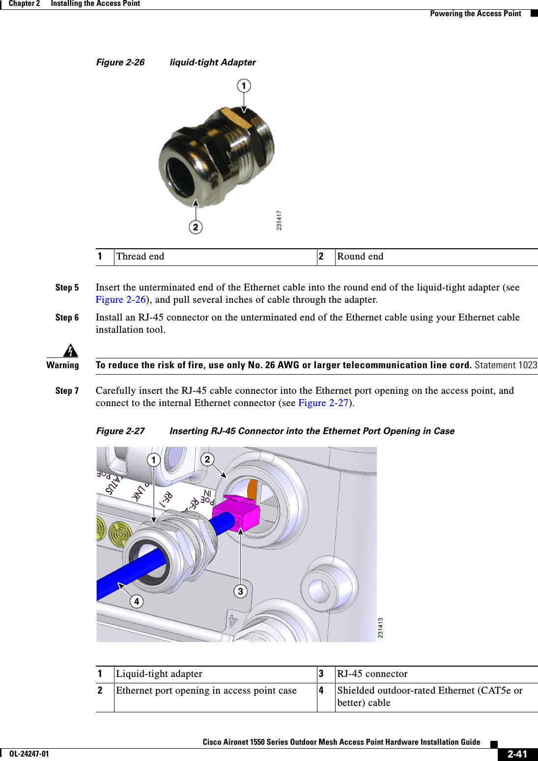
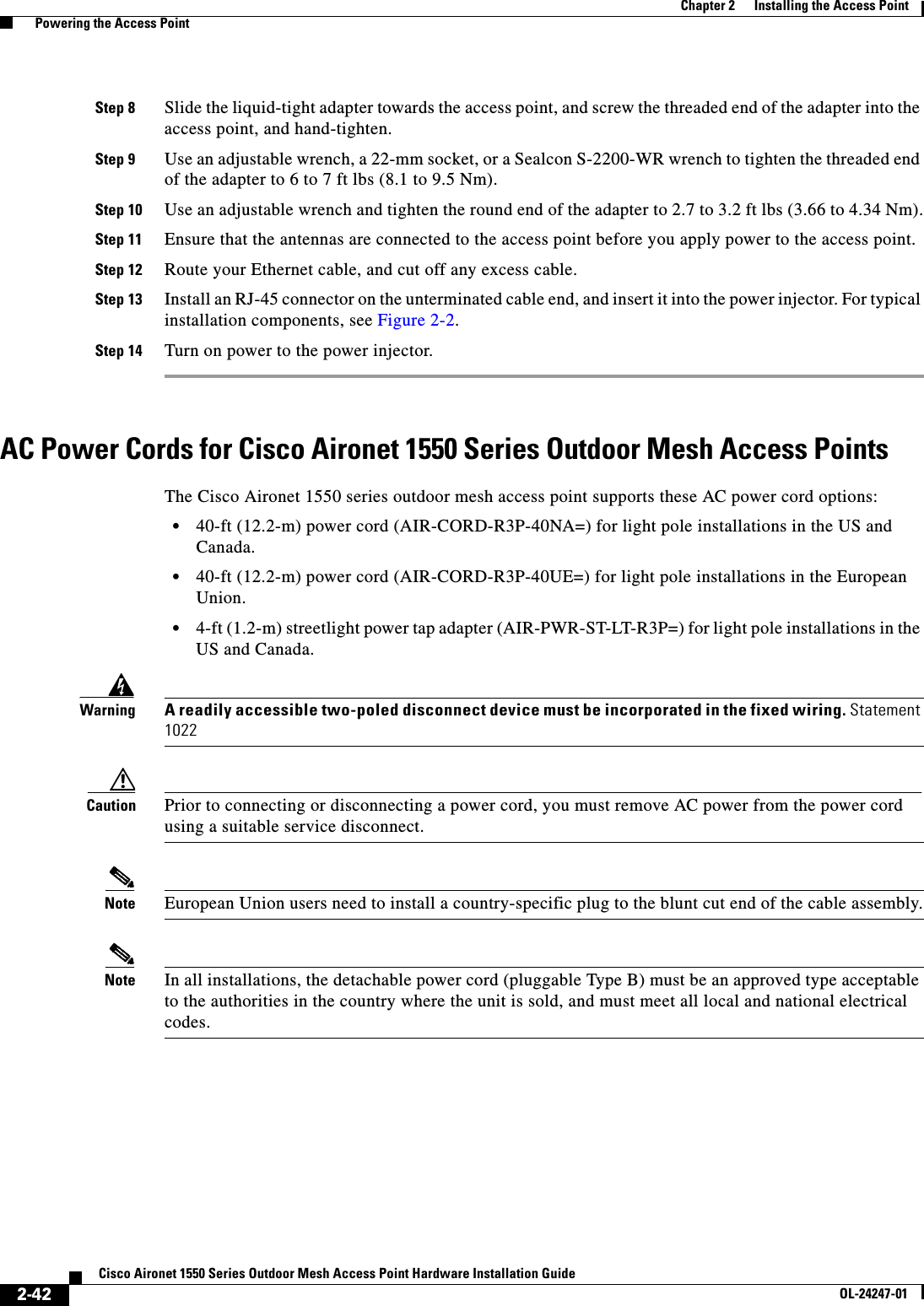
CHAPTER 2-1Cisco Aironet 1550 Series Outdoor Mesh Access Point Hardware Installation GuideOL-24247-012Installing the Access PointThis chapter describes how to install the 1552 access point and contains the following sections:•Unpacking the Access Point, page 2-2•Tools and Hardware, page 2-2•Warnings, page 2-4•Safety Information, page 2-5•Avoiding Damage to Radios in a Testing Environment, page 2-7•Installation Guidelines, page 2-8•Installing the Access Point, page 2-15•Grounding the Access Point, page 2-34•Connecting a Fiber-Optic Cable to the Access Point, page 2-35•Powering the Access Point, page 2-38•Installing the Access Point in Hazardous Locations, page 2-53
 2-2Cisco Aironet 1550 Series Outdoor Mesh Access Point Hardware Installation GuideOL-24247-01Chapter 2      Installing the Access Point  Unpacking the Access PointUnpacking the Access PointWhen you are unpacking the access point, do not remove the foam blocks attached to the antenna connectors. The foam protects the antenna connectors during installation.To unpack the access point, follow these steps:Step 1 Open the shipping container and carefully remove the contents. Step 2 Return all packing materials to the shipping container, and save it.Step 3 Ensure that all items listed in “Package Contents” are included in the shipment. If any item is damaged or missing, notify your authorized Cisco sales representative. Package ContentsThe typical access point package contains the following items:•Access point •Cisco product documentation and translated safety warnings•Three liquid-tight adapters •Two-pin DC power connector•Ground lug (Panduit PLCD6-10A-L) and screws with lock washers•Watertight cable glands for Power-over-Ethernet (PoE) ports (depending on the 1552 access point model, 2 or 3 cable glands are provided)Tools and HardwareThe tools and hardware used to install the 1552 access point are described in:•Optional Tools and Hardware, page 2-2•Optional Tools and Hardware That You Supply, page 2-3•Pole Installation Hardware and Tools, page 2-3•Cable Strand Installation Hardware and Tools, page 2-4Optional Tools and HardwareThe optional tools and hardware that can be obtained from Cisco are:•Optional power injector (AIR-PWRINJ1500-2=)•Optional AC power cord–40-ft (12.2-m) power cord with North American plug (AIR-CORD-R3P-40NA=) for light pole installations in the US and Canada–AC power cord, 40 ft (12.2 m) with European unterminated end (AIR-CORD-R3P-40UE=) for light pole installations outside of the US and Canada
 2-3Cisco Aironet 1550 Series Outdoor Mesh Access Point Hardware Installation GuideOL-24247-01Chapter 2      Installing the Access Point  Tools and Hardware–4-ft (1.2-m) streetlight power tap adapter (AIR-PWR-ST-LT-R3P=) for light pole installations in the US and Canada•Antennas, 2.4/5-GHz (refer to the “Antenna Configurations” section on page 1-12)•Optional battery backup unit (AIR-1520-BATT-6AH=)—Used only on model 1552E•Optional pole mount kit (AIR-ACCPMK1550=) •Optional strand mount kit (AIR-ACCSMK1550=) •Optional banding strap tool (BAND IT) (AIR-BAND-INST-TL=)•Optional fiber-optic 100BASE-BX10-U SFP, fiber-optic take-up reels, and liquid-tight adapter (GLC-FE-100BX-URGD=)Optional Tools and Hardware That You SupplyTools and materials that are user-supplied are:•Ground lug crimping tool (Panduit CT-720 with CD-720-1 die) •6-AWG copper ground wire•13 mm box-end wrench or socket set •Adjustable wrench, 22 mm socket, or Sealcon S-2200-WR socket wrench•#8 Torx screwdriver•Small flat screwdriver for DC power connector•Optional shielded outdoor-rated Ethernet (CAT5e or better) cable with 0.20 to 0.35 in (0.51 to 0.89 cm) diameter•Optional Ethernet RJ-45 connector and installation tool•Optional shielded outdoor-rated DC power cable with 0.20 to 0.35 inch (.0.51 to 0.89 cm) diameter•Optional cable F-connector adapter (stinger)•Optional ground rod, as required by local regulations•Optional ladder, power lift, rope, or other tools as requiredPole Installation Hardware and ToolsTo install the access point on a vertical or horizontal metal, wood, or fiberglass pole, you need the following additional hardware and tools:•Pole mount kit (AIR-ACCPMK1550=)–Pole clamp bracket–Two gusset strap brackets–One mounting bracket–Twelve hex bolts (M8 x16)–One M8 flange nut–Six M8 flat washers–Ten M8 split lock washers
 2-4Cisco Aironet 1550 Series Outdoor Mesh Access Point Hardware Installation GuideOL-24247-01Chapter 2      Installing the Access Point  Warnings–Two stainless steel mounting straps•Customer banding strap tool (BAND IT)—(AIR-BAND-INST-TL=)•Customer-supplied 13-mm and box-end wrench or socket set•Customer-supplied adjustable wrench, 22 mm socket, or Sealcon S-2200-WR socket wrench Cable Strand Installation Hardware and ToolsTo install the access point on a cable strand, you need the following additional parts:•Cable strand mount kit (AIR-ACCSMK1550=) –Four hex bolts (M8, 0x16mmL)–Four M8 split lock washers (0.14 8mmoD, 2mmT)–Four M8 flat washers (16.0mmOD, 1.6mmT)–Two carriage bolt fasteners (5/16-18 x 1.25 in.)–Six hex nuts, serrated flange (5/16-18)–Four carriage bolts (5/16 x 5/8LG) –Strand mounting brackets—1 left bracket, 1 right bracket, 2 adjustable brackets–Four strap clamps•Customer-supplied 13-mm box-end wrench or socket set•Customer-supplied adjustable wrench, 22 mm socket, or Sealcon S-2200-WR socket wrench WarningsTranslated versions of all safety warnings are available in the safety warning document that shipped with your access point or on Cisco.com. To browse to the document on Cisco.com, refer to Appendix A, “Translated Safety Warnings” for instructions. WarningIMPORTANT SAFETY INSTRUCTIONSThis warning symbol means danger. You are in a situation that could cause bodily injury. Before you work on any equipment, be aware of the hazards involved with electrical circuitry and be familiar with standard practices for preventing accidents. Use the statement number provided at the end of each warning to locate its translation in the translated safety warnings that accompanied this device. Statement 1071SAVE THESE INSTRUCTIONSWarningThis equipment is to be installed by trained and qualified personnel, as per these installation instructions. The installer is responsible for obtaining any required local or national safety inspections of the structural integrity of the installation by the local authority/inspection department.WarningDo not operate the unit near unshielded blasting caps or in an explosive environment unless the device has been modified to be especially qualified for such use. Statement 364
 2-5Cisco Aironet 1550 Series Outdoor Mesh Access Point Hardware Installation GuideOL-24247-01Chapter 2      Installing the Access Point  Safety InformationWarningThe cables specified in this installation guide that are used with the specified liquid-tight adapters provide protection against ingress of moisture for a Type 4/IP67 classified enclosure. If substitute cable are used, the installer must ensure that the size (OD) of the cable meets the acceptable range allowed by the liquid-type adaptor.WarningThis equipment must be externally grounded using a customer-supplied ground wire before power is applied. Contact the appropriate electrical inspection authority or an electrician if you are uncertain that suitable grounding is available. Statement 366WarningRead the installation instructions before connecting the system to the power source. Statement 1004WarningUltimate disposal of this product should be handled according to all national laws and regulations. Statement 1040Safety InformationFollow the guidelines in this section to ensure proper operation and safe use of the access point.FCC Safety Compliance StatementThe FCC, with its action in ET Docket 96-8, has adopted a safety standard for human exposure to RF electromagnetic energy emitted by FCC-certified equipment. When used with approved Cisco Aironet antennas, Cisco Aironet products meet the uncontrolled environmental limits found in OET-65 and ANSI C95.1, 1991. Proper operation of this radio device according to the instructions in this publication results in user exposure substantially below the FCC recommended limits.Safety PrecautionsWarningIn order to comply with radio frequency (RF) exposure limits, the antennas for this product should be positioned no less than 6.56 ft (2 m) from your body or nearby persons. Statement 339WarningThe AC power supply has double pole/neutral fusing. Statement 188WarningDo not work on the system or connect or disconnect cables during periods of lightning activity. Statement 1001
 2-6Cisco Aironet 1550 Series Outdoor Mesh Access Point Hardware Installation GuideOL-24247-01Chapter 2      Installing the Access Point  Safety InformationWarningClass 1 laser product. Statement 1008WarningThere is the danger of explosion if the battery is replaced incorrectly. Replace the battery only with the same or equivalent type recommended by the manufacturer. Dispose of used batteries according to the manufacturer’s instructions. Statement 1015WarningA readily accessible two-poled disconnect device must be incorporated in the fixed wiring. Statement 1022WarningTo reduce the risk of fire, use only No. 26 AWG or larger telecommunication line cord. Statement 1023WarningThis unit might have more than one power supply connection. All connections must be removed to de-energize the unit. Statement 1028WarningOnly trained and qualified personnel should be allowed to install, replace, or service this equipment. Statement 1030WarningConnect the unit only to DC power source that complies with the safety extra-low voltage (SELV) requirements in IEC 60950 based safety standards. Statement 1033WarningWhen installing or replacing the unit, the ground connection must always be made first and disconnected last. Statement 1046.WarningDo not locate the antenna near overhead power lines or other electric light or power circuits, or where it can come into contact with such circuits. When installing the antenna, take extreme care not to come into contact with such circuits, because they may cause serious injury or death. For proper installation and grounding of the antenna, please refer to national and local codes (for example, U.S.:NFPA 70, National Electrical Code, Article 810, Canada: Canadian Electrical Code, Section 54). Statement 1052Caution Before connecting or disconnecting a power cord, you must remove AC power from the power cord using a suitable service disconnect.For additional important safety instructions for AC power cords, refer to the AC Power Cords for Cisco Aironet 1550 Series Outdoor Mesh Access Points document that shipped with your AC power cords.For safety and to achieve a good installation, please read and follow these safety precautions:
 2-7Cisco Aironet 1550 Series Outdoor Mesh Access Point Hardware Installation GuideOL-24247-01Chapter 2      Installing the Access Point  Avoiding Damage to Radios in a Testing Environment•Select your installation site with safety, as well as performance in mind. Remember: electric power lines and phone lines look alike. For safety, assume that any overhead line can kill. •Call your electric power company. Tell them your plans, and ask them to come look at your proposed installation. •Plan your installation carefully and completely before you begin. Successful raising of a mast or tower is largely a matter of coordination. Each person should be assigned to a specific task and should know what to do and when to do it. One person should be in charge of the operation to issue instructions and watch for signs of trouble.•When installing the access point and antennas, remember:–Do not use a metal ladder.–Do not work on a wet or windy day.–Do dress properly—shoes with rubber soles and heels, rubber gloves, long sleeved shirt or jacket.•Use a rope to lift the access point. If the assembly starts to drop, get away from it and let it fall. •If any part of the antenna system should come in contact with a power line, do not touch it or try to remove it yourself. Call your local power company. They will remove it safely. If an accident should occur, call for qualified emergency help immediately.Avoiding Damage to Radios in a Testing EnvironmentThe radios on outdoor units (bridges) have higher transmit power levels than radios on indoor units (access points). When you test high-power radios in a link, you must avoid exceeding the maximum receive input level for the receiver. At levels above the normal operating range, packet error rate (PER) performance is degraded. At even higher levels, the receiver can be permanently damaged. To avoid receiver damage and PER degradation, you can use one of the following techniques:•Separate the omnidirectional antennas by at least 2 ft (0.6 m) to avoid receiver damage or by at least 25 ft (7.6 m) to avoid PER degradation.Note These distances assume free space path loss and are conservative estimates. Required separation distances for damage and performance degradation levels in actual deployments are less if conditions are not non-line-of-sight.•Reduce the configured transmit power to the minimum level.•Use directional antennas, and keep them away from each other.•Cable the radios together using a combination of attenuators, combiners, or splitters to achieve a total attenuation of at least 60 dB.For a radiated test bed, the following equation describes the relationships among transmit power, antenna gain, attenuation, and receiver sensitivity:txpwr + tx gain + rx gain - [attenuation due to antenna spacing] < max rx input levelWhere:txpwr = Radio transmit power leveltx gain = transmitter antenna gainrx gain = receiver antenna gain
 2-8Cisco Aironet 1550 Series Outdoor Mesh Access Point Hardware Installation GuideOL-24247-01Chapter 2      Installing the Access Point  Installation GuidelinesFor a conducted test bed, the following equation describes the relationships among transmit power, antenna gain, and receiver sensitivity:txpwr - [attenuation due to coaxial components] < max rx input levelCaution Under no circumstances should you connect the antenna port from one access point to the antenna port of another access point without using an RF attenuator. If you connect antenna ports, you must not exceed the maximum survivable receive level of 0 dBm. Never exceed 0 dBm, or damage to the access point can occur. Using attenuators, combiners, and splitters having a total of at least 60 dB of attenuation ensures that the receiver is not damaged and that PER performance is not degraded.Installation GuidelinesBecause the access point is a radio device, it is susceptible to common causes of interference that can reduce throughput and range. Follow these basic guidelines to ensure the best possible performance:•For information on planning and initially configuring your Cisco Mesh network, refer to the Cisco Wireless Mesh Access Points, Design and Deployment Guide, Release 7.0.•Review the FCC guidelines for installing and operating outdoor wireless LAN devices at http://www.cisco.com/en/US/partner/prod/collateral/routers/ps272/data_sheet_c78-647116_ps11451_Products_Data_Sheet.html.•Perform a site survey before beginning the installation.•Install the access point in an area where structures, trees, or hills do not obstruct radio signals to and from the access point.•The access points can be installed at any height, but best throughput is achieved when all the access points are mounted at the same height. We recommend installing the access points no higher than 40 feet to allow support for wireless clients on the ground.Note To calculate path loss and to determine how far apart to install access points, consult an RF planning expert.Site SurveysEvery network application is a unique installation. Before installing multiple access points, you should perform a site survey to determine the optimum use of networking components and to maximize range, coverage, and network performance.Consider the following operating and environmental conditions when performing a site survey:•Data rates—Sensitivity and range are inversely proportional to data bit rates. The maximum radio range is achieved at the lowest workable data rate. A decrease in receiver sensitivity occurs as the radio data increases.•Antenna type and placement—Proper antenna configuration is a critical factor in maximizing radio range. As a general rule, range increases in proportion to antenna height. However, do not place the antenna higher than necessary, because the extra height also increases potential interference from other unlicensed radio systems and decreases the wireless coverage from the ground.•Physical environment—Clear or open areas provide better radio range than closed or filled areas.
 2-9Cisco Aironet 1550 Series Outdoor Mesh Access Point Hardware Installation GuideOL-24247-01Chapter 2      Installing the Access Point  Installation Guidelines•Obstructions—Physical obstructions such as buildings, trees, or hills can hinder performance of wireless devices. Avoid locating the devices in a location where there is an obstruction between the sending and receiving antennas.Before Beginning the InstallationBefore you begin the installation process:•Ensure that a site survey has been performed.•Ensure that your network infrastructure devices are operational and properly configured.•Ensure that your controllers are connected to switch trunk ports.•Ensure that your switch is configured with untagged access ports for connecting your access points.•Ensure that a DHCP server with Option 43 configured is reachable by your access points, or manually configure the controller information in the access point (for additional information, refer to the “Configuring DHCP Option 43” section on page F-1).•Become familiar with the access point installation components (see the “Becoming Familiar with Access Point Installation Components” section on page 2-9).Becoming Familiar with Access Point Installation ComponentsThe access point is designed to be installed in an outdoor environment, such as the exterior roof overhang of a tall building or a streetlight pole. Carefully review the following figures to become familiar with the system components, connectors, indicators, cables, system interconnection, and grounding:•Components in a typical access point installation (see Figure 2-1)•Pole mount installation (see Figure 2-2)•Cable strand mount installation (see Figure 2-3•Streetlight power tap installation (see Figure 2-4)Note The illustrations in this document show all available connections for the access point. Unused connections are capped with a connector plug to ensure the watertight integrity of the access point. liquid-tight adapters are provided for connector openings, which can be installed before or after deploying the access point.
 2-10Cisco Aironet 1550 Series Outdoor Mesh Access Point Hardware Installation GuideOL-24247-01Chapter 2      Installing the Access Point  Installation GuidelinesFigure 2-1 Components in a Typical Access Point InstallationNote The 1552 access point was designed with consideration for resistance to effects of lightning effects on the access point electronics. The 1552 access point employs lightning arrestor circuitry on the Ethernet and power ports. On the input Ethernet port, Gas Discharge Tubes (GDT) are used for the Power Entry Module (PEM) to mitigate lightning effect. On the AC power, GDTs are also used along with fuses to mitigate high-current condition. For the DC power, a fuse is used to mitigate high current condition.While not a common practice, the user may want to consider using lightning protection at the antenna ports for added protection. To meet EN/IEC60950-22 (Clause 4.2) requirements, the installer must ensure that additional protection is provided external to this equipment to reduce transient surges from Overvoltage IV to Overvoltage Category II at the AC power input of the access point. The over-voltage and fault-current protection components used to achieve this protection must comply with the IEC 61643 1Building roof-overhang 6Ground2Shielded outdoor-rated Ethernet(CAT5e or better) cable11. User supplied.7AC power cord22. The safety ground wire in the AC power cord must have a ground path to a grounding rod.3Water drip loop 8Power injector33. The shielded Ethernet cable has a ground path through the power injector and the safety ground wire in the AC power cord.46-AWG copper grounding wire1 9Shielded Ethernet (CAT5e or better) cable15Ground rod1 10 Controller (through a switch)281938110 89765432
 2-11Cisco Aironet 1550 Series Outdoor Mesh Access Point Hardware Installation GuideOL-24247-01Chapter 2      Installing the Access Point  Installation Guidelinesseries of standards. To meet CAN/CSA-C22.2 No. 60950-22-07/UL60950-22 requirements, the installer may use alternative components to provide this additional protection. Those components may comply with ANSI/IEEE C62.11, CSA Certification Notice No. 516, CSA C22.2 No. 1, or UL 1449. Suitability of the components for the application must be determined for the intended installation. (For example, some devices are suitable for installation on the load side of the service entrance only, and some are suitable for use with cord-connected equipment only.)WarningInstallation of the equipment must comply with local and national electrical codes. Statement 1074Figure 2-2 Pole Mount Installation 1Stainless steel mounting straps (part of pole mount kit)4Cisco Aironet Dual-Band Omnidirectional Antennas. The dual-band antenna covers both the 2.4 GHz and 5 GHz bands.2Pole (wood, metal, or fiberglass)2 to 16 in. (5.1 to 40.6 cm) diameter51552 series access point, models:•AIR-CAP1552E-x-K9, or•AIR-CAP1552H-x-K93Mounting bracket (part of pole mount kit)14124425523953
 2-12Cisco Aironet 1550 Series Outdoor Mesh Access Point Hardware Installation GuideOL-24247-01Chapter 2      Installing the Access Point  Installation GuidelinesFigure 2-3 Cable Strand Mounting Example - Shown on a 1552 Model AIR-CAP1552C-x-K9Figure 2-4 Streetlight Power Tap Adapter Installation 1Cable Strand Mounting Kit brackets 4Low-profile dual-band (2.4 GHz and 5 GHz) 3-element array antenna unit2Strand support cable 5F-connector adapter for the POC cable (only on model AIR-CAP1552C-x-K9)3Cable bundle2552461431251Outdoor light control 36-AWG copper grounding wire2Streetlight power tap adapter281939123
 2-13Cisco Aironet 1550 Series Outdoor Mesh Access Point Hardware Installation GuideOL-24247-01Chapter 2      Installing the Access Point  Installation GuidelinesAntenna N-Type Connector LocationsThe access point antenna N-type connectors are located on the bottom of Models AIR-CAP1552E-x-K9 and AIR-CAP1552H-x-K. The N-type connectors support the Cisco Aironet AIR-ANT2547V-N Dual-Band Omnidirectional Antennas. Figure 2-5 shows the antenna port locations viewed from the RF cover side.Figure 2-5 Antenna Port Locations - Models AIR-CAP1552E-x-K9 and AIR-CAP1552H-x-K9Adding the Access Point MAC Addresses to the Controller Filter ListBefore installing your access points, configure your controller by adding the MAC addresses of the access points to the filter list. MAC address filtering is enabled by default. This enables the controller to respond to the listed access points. To add a MAC filter entry on the controller, follow these steps:Step 1 Log into your controller using a web browser.Step 2 Choose SECURITY > MAC Filtering > New.Step 3 Enter the MAC address of the access point to the MAC Filter list; for example, 00:0B:91:21:3A:C7.Note The access point MAC address is located on the bottom of the unit. When two MAC addresses are shown, use the top MAC address.Step 4 Select a WLAN ID or Any WLAN from the WLAN ID pop-up menu. 1Not used 4Antenna port 4 (with caps)2Not used 5Antenna port 5 (with caps)3Not used 6Antenna port 6 (with caps)255247123456
 2-14Cisco Aironet 1550 Series Outdoor Mesh Access Point Hardware Installation GuideOL-24247-01Chapter 2      Installing the Access Point  Installation GuidelinesStep 5 Enter a description (32 characters maximum) of the access point in the Description field; for example, Fisher_Street_00.0B.91.21.3A.C7 shows the location and MAC address of the access point.Step 6 Choose an interface from the Interface Name pop-up menu, and click Apply.Step 7 Repeat Steps 2 to 6 to add other access points to the list.Step 8 Log out of your controller, and close your web browser.Configuring a RAP The access point defaults to the mesh access point (MAP) radio role. One or more of your access points must be reconfigured as a root access point (RAP). The RAPs connect to a wired Ethernet link through a switch to the controller. The MAPs use their wireless backhaul interface to connect to a RAP to reach the controller.To configure a RAP on the controller GUI, follow these steps:Step 1 Log into your controller using a web browser.Step 2 Click Wireless. When your access point associates to the controller, the name of the access point appears in the AP Name list.Step 3 Double-click your access point name. Step 4 Find Mesh Information, and choose Root AP by clicking the drop-down arrow in the AP Role field.Step 5 Click Apply.Step 6 Repeat Steps 2 through 5 for each RAP.Step 7 Log out from your controller, and close your web browser.Configuring a Bridge Group NameThe bridge group name (BGN) controls the association of the access points to a RAP. BGNs can be used to logically group the radios to avoid different networks on the same channel from communicating with each other. This setting is also useful if you have more than one RAP in your network in the same area.If you have two RAPs in your network in the same area (for more capacity), we recommend that you configure the two RAPs with the same BGN, but on different channels.The BGN is a string of ten characters maximum. A factory-set bridge group name (NULL VALUE) is assigned during manufacturing. It is not visible to you, but allows new access point radios to join a network of new access points. The BGN can be reconfigured from the Controller CLI and GUI. After configuring the BGN, the access point reboots.The BGN should be configured very carefully on a live network. You should always start from the farthest node (last node) from the RAP and move towards the RAP. If you start configuring the BGN in a different location, then the access points beyond this point (farther away) are dropped, as they have a different BGN.
 2-15Cisco Aironet 1550 Series Outdoor Mesh Access Point Hardware Installation GuideOL-24247-01Chapter 2      Installing the Access Point  Installing the Access PointTo configure the BGN for the access points using the GUI, follow these steps:Step 1 Log into your controller using a web browser.Step 2 Click Wireless. When access points associates to the controller, the name of the access point appears in the AP Name list.Step 3 Double-click on an access point name. Step 4 Find Mesh Information, and enter the new BGN in the Bridge Group Name field.Step 5 Click Apply.Step 6 Repeat Steps 2 through 5 for each access point.Step 7 Log out from your controller, and close your web browser.Installing the Access PointThis section provides instructions for installing your access points. Personnel installing the access point must understand wireless access points and bridging techniques and grounding methods. Caution All installation methods for mounting an access point on any wall surface is subject to the acceptance of local jurisdiction.Installation OptionsThere are two optional installation kits: •Pole mount kit—Used for pole, wall, or streetlight installations•Strand mount kit—Used for cable strand installations WarningOnly trained and qualified personnel should be allowed to install, replace, or service this equipment. Statement 1030WarningInstallation of the equipment must comply with local and national electrical codes. Statement 1074Caution To provide inline PoE, you must use the power injector (AIR- PWRINJ1500-2=) specified for the access point. Other power injectors, PoE switches, and 802.3af power sources do not provide adequate power, which might cause the access point to malfunction and cause over-current conditions at the power source. You must ensure that the switch port connected to the access point has PoE turned off.
 2-16Cisco Aironet 1550 Series Outdoor Mesh Access Point Hardware Installation GuideOL-24247-01Chapter 2      Installing the Access Point  Installing the Access PointRefer to these sections for installation details:•Access Point Mounting Orientation, page 2-16•Mounting the Access Point on a Wall, page 2-16•Mounting the Access Point on a Pole, page 2-19•Cable Strand Mounting, page 2-26Access Point Mounting OrientationWhen mounting an access point on a horizontal or vertical surface, you must ensure that the access point is oriented with the LED indicators pointing down (see Figure 2-2, Figure 2-3, and Figure 2-4). This positioning allows the LEDs to be visible to someone on the ground below the access point.You must also ensure the access point is mounted with the hinged access cover facing out.Note Omnidirectional antennas are vertically polarized and should be mounted vertically with the antennas facing down.Mounting the Access Point on a WallThe optional pole mount kit contains a mounting bracket for wall mounting. You can use the mounting bracket as a template to mark the positions of the mounting holes for your installation. You then install the mounting plate, and attach the access point when you are ready. Table 2-1 lists the material that you will need to provide in addition to the pole mount kit.Table 2-1 Material Needed to Mount Access Point to a Vertical Wall Materials Required In Kit•Ground lug and screws (provided with access point)•Crimping tool for ground lug, Panduit CT-720 with CD-720-1 die (http://onlinecatalog.panduit.com) •Four M8 or 5/16 in. (31 mm) screws•Four wall anchors (specified for wall material)•Drill bit for wall anchors•Electric drill and standard screwdriver•#6-AWG ground wire•Shielded outdoor-rated Ethernet (CAT5e or better) cable•Grounding block•Grounding rod•13-mm box-end wrench or socket setYesNoNoNoNoNoNoNoNoNoNo
 2-17Cisco Aironet 1550 Series Outdoor Mesh Access Point Hardware Installation GuideOL-24247-01Chapter 2      Installing the Access Point  Installing the Access PointCaution The mounting surface, attaching screws, and optional wall anchors must be able to support a 50-lb(22.7 kg) static weight. To mount the access point on a vertical wall, follow these instructions: Step 1 Use the mounting bracket as a template to mark four screw hole locations on your mounting surface. See Figure 2-6 for the mounting bracket screw hole locations. You can optionally use the individual mounting holes or the mounting slots.Caution The mounting surface, attaching screws, and optional wall anchors must be able to support a 50-lb (22.7 kg) static weight. Figure 2-6 Mounting Bracket for Wall MountingStep 2 Use four customer-supplied screws and optional screw anchors to attach the mounting plate to the mounting surface.Note If necessary, use suitable screw anchors and an exterior-grade plywood backboard to mount the access point to stucco, cement, or drywall.1Access point quick mount notch 3Mounting slots (allows bracket rotation)2Mounting holes23122552521
 2-18Cisco Aironet 1550 Series Outdoor Mesh Access Point Hardware Installation GuideOL-24247-01Chapter 2      Installing the Access Point  Installing the Access PointStep 3 Screw a M8 x16 bolt in the top support bolt hole on each side the access point (see Figure 2-7). Do not screw the bolt all the way in; leave approximately a 0.25 inch (0.635 cm) space.Figure 2-7 Location of Access Point Top Support Bolt HoleStep 4 Position the two bolts on the access point into the quick mount notches on each side of the mounting bracket (see Figure 2-2). Ensure that the hinged door is facing out.Step 5 Screw a M8 x16 bolt (with flat and lock washers) into the second bolt hole on each side of the access point. Step 6 Ensure that the front of the access point is vertical, and tighten the four bolts to 13 to 15 ft lbs (17.6 to 20.3 Nm).Step 7 When using the Cisco Aironet Dual-Band Omnidirectional Antennas, connect them to the access point as shown in Figure 2-2. Hand-tighten the antennas to the access point.Step 8 Continue with the “Grounding the Access Point” section on page 2-34 and the “Powering the Access Point” section on page 2-38.1M8 x16 bolt (supplied with pole mount kit) 3Ground lug location2M8 x16 bolt (supplied with pole mount kit)255244123
 2-19Cisco Aironet 1550 Series Outdoor Mesh Access Point Hardware Installation GuideOL-24247-01Chapter 2      Installing the Access Point  Installing the Access PointMounting the Access Point on a PoleWhen installing an access point on a vertical pole, mast, or a streetlight pole, you should use the optional Cisco pole mount kit. The kit supports metal, wood, or fiberglass poles from 2 to 16 inches in diameter.Assembling the Pole Clamp Bracket and the Mounting BracketWhen installing an access point on a pole, mast, or a streetlight, you should use the optional Cisco pole mount kit. The kit supports metal, wood, or fiberglass poles from 2 to 16 inches in diameter.The pole mount kit contains several parts that you must assemble prior to mounting on a pole. First you need to assemble two strap brackets on the pole clamp bracket that are positioned for the pole diameter you are using to mount the access point. Figure 2-8 illustrates the pole diameter indicators and bolt holes on the pole clamp bracket.Figure 2-8 Pole Clamp Bracket Adjustment Hole LocationsTo assemble the pole clamp bracket, follow these steps:1Pole size indicators •2 to 6 in. •6 to 11 in. •11 to 16 in.2Bolt holes for pole diameters (11 to 16 inches indicated)
 2-20Cisco Aironet 1550 Series Outdoor Mesh Access Point Hardware Installation GuideOL-24247-01Chapter 2      Installing the Access Point  Installing the Access PointStep 1 Position the strap brackets on the pole clamp bracket for the pole diameter you are using and secure each strap bracket with two M8 x16 bolts (with lock washers) (see Figure 2-9). Tighten the bolts to 13 to 15 ft lbs (17.6 to 20.3 Nm).Figure 2-9 Assembled Pole Clamp Bracket and Strap BracketsStep 2 Screw the M8 nut onto the pole clamp bracket support bolt, and tighten just enough to prevent the bolt from falling off.Step 3 Go to the “Pole Mounting” section on page 2-21.1M8 x1.25x16 bolts (with lock washers) 3Strap bracket (shown positioned for 11 to 16 inch diameter pole)2Pole clamp bracket
 2-21Cisco Aironet 1550 Series Outdoor Mesh Access Point Hardware Installation GuideOL-24247-01Chapter 2      Installing the Access Point  Installing the Access PointPole MountingThe access point can be installed where power is available, without the need for a wired LAN connection. The access point uses intelligent wireless routing that is based on the Adaptive Wireless Path Protocol (AWPP). AWPP enables a remote access point to dynamically optimize the best route to the wired LAN network using another access point. The 1522 access point uses the 5-GHz radio for the Mesh backhaul and connections. The 2.4-GHz radio is used for local wireless client access. To mount your access point on a vertical pole or streetlight pole, you need to install two metal bands around the pole to support the access point. This process requires extra tools and material not provided in the pole mount kit (see Table 2-2).To mount the access point onto a vertical pole or streetlight pole, follow these steps:Step 1 Select a mounting location on the pole to mount the access point. You can attach the access point to any pole from 2 to 16 inch (5.1 to 40.6 cm) in diameter.Note If you will be using a streetlight power tap adapter, position the access point within 3 ft (1 m) of the outdoor light control.Step 2 For poles larger than 3.5 inch (8.9 cm), mount the pole clamp bracket assembly to a pole (see Figure 2-10) using two metal straps. Following the instructions provided with the banding strap tool (BAND IT) (AIR-BAND-INST-TL=), loop each metal strap twice through the slots on the strap bracket.Caution Do not place the metal straps in the large open area between the pole clamp bracket and the strap brackets, because this does not properly secure the access point.Table 2-2 Material Needed to Mount Access Point on a Pole Mounting Method Materials Required In KitVertical or streetlight pole •Two 0.75-in (1.9 cm) stainless steel bands•Banding strap tool (BAND IT) (Cisco AIR-BAND-INST-TL=)•Ground lug (provided with access point)•Crimping tool for ground lug, Panduit CT-720 with CD-720-1 die (http://onlinecatalog.panduit.com) •#6 AWG ground wireYesNoYesNoNo
 2-22Cisco Aironet 1550 Series Outdoor Mesh Access Point Hardware Installation GuideOL-24247-01Chapter 2      Installing the Access Point  Installing the Access PointFigure 2-10 Clamp Bracket Assembly Mounted on Poles Larger than 3.5 inch (8.9 cm)Step 3 For pole diameters of 3.5 inch (8.9 cm) or less, mount the pole clamp bracket assembly to a pole using two metal straps looped through the space between the pole clamp bracket and the strap brackets (see Figure 2-11) to provide maximum holding strength for extreme environments. Following the instructions provided with the banding strap tool (BAND IT) (AIR-BAND-INST-TL=), loop each metal strap twice.1Pole clamp bracket 3Metal mounting strap2Strap slot in strap bracket 4Pole
 2-23Cisco Aironet 1550 Series Outdoor Mesh Access Point Hardware Installation GuideOL-24247-01Chapter 2      Installing the Access Point  Installing the Access PointFigure 2-11 Metal Strap Open Space for 3.5 inch (8.9 cm) and Smaller Poles Caution Do not place the metal straps in the large open area between the pole clamp bracket and the strap brackets because this does not properly secure the access point.Step 4 Position the pole clamp bracket on the pole as needed before tightening the metal bands.Note When the metal bands are tightened to the full tension, the pole clamp bracket cannot be adjusted unless the metal bands are cut or disassembled.Step 5 Tighten the metal bands using the banding strap tool (BAND IT) (Cisco AIR-BAND-INST-TL=) by following the operating instructions in the box with the tool. Ensure that the metal bands are as tight as possible.Step 6 Place the mounting bracket onto the pole clamp bracket support bolt (see Figure 2-12).Step 7 For vertical poles, position the mounting bracket as shown in Figure 2-12. For horizontal streetlight poles, rotate the mounting bracket 90o from the position shown in Figure 2-12.1Metal strap open space
 2-24Cisco Aironet 1550 Series Outdoor Mesh Access Point Hardware Installation GuideOL-24247-01Chapter 2      Installing the Access Point  Installing the Access PointStep 8 Install four M8 x16 bolts (with flat and lock washers) into the bolt holes.Figure 2-12 Screw Hole Locations on the Mounting Bracket and Pole Clamp Bracket AssemblyStep 9 Hand-tighten the bolts and the nut (do not overtighten).Step 10 Adjust the top edge of the mounting bracket until it is horizontal and tighten the bolts and the flange nut (see Figure 2-12) to 13 to 15 ft lbs (17.6 to 20.3 Nm).Note The mounting bracket can be adjusted up to 45o to compensate for tilted horizontal streetlight poles. Step 11 Screw a M8 x16 bolt (without a flat or lock washer) in the top support bolt hole on each side the access point (see Figure 2-13). Do not screw the bolt all the way in. Leave a gap of approximately 0.25 inch (0.635 cm).1Pole clamp bracket assembly 3Bolt holes 2Access point support bolt (M8 flange nut not shown)4Mounting bracket281940123433
 2-25Cisco Aironet 1550 Series Outdoor Mesh Access Point Hardware Installation GuideOL-24247-01Chapter 2      Installing the Access Point  Installing the Access PointFigure 2-13 Location of Access Point Top Support Bolt HolesStep 12 Position the two bolts on the access point into the access point quick-mount notch on the mounting bracket (see Figure 2-14).Note The access point should be positioned with the LEDs on the bottom to allow viewing from the ground and with the hinged cover facing out.1Ground lug screw holes location 3Second M8 x16 bolt hole location2M8 x16 bolt hole (bolts are supplied with pole mount kit; install without flat or lock washers)122552543
 2-26Cisco Aironet 1550 Series Outdoor Mesh Access Point Hardware Installation GuideOL-24247-01Chapter 2      Installing the Access Point  Installing the Access PointFigure 2-14 Access Point Hanging in Mounting BracketStep 13 Screw a M8 x16 bolt (with flat and lock washers) into the second bolt hole on each side of the access point (see Figure 2-14). Step 14 Ensure that the front of the access point is vertical, and tighten the four bolts to 13 to 15 ft lbs (17.6 to 20.3 Nm).Step 15 When using the Cisco Aironet Dual-Band Omnidirectional Antennas, connect them to the access point as shown in Figure 2-14. Hand-tighten the antennas to the access point.Step 16 Continue with the “Grounding the Access Point” section on page 2-34 and the “Powering the Access Point” section on page 2-38.Cable Strand MountingWhen mounting the access point on a cable strand, you must use the optional strand mount kit. The kit contains several parts that you should assemble before mounting on a cable strand. To install the access point to a cable strand, you need to perform these operations:•Assemble cable brackets; attach cable clamps to the clamp bracket.•Attach the strand brackets to the access point.•Attach the clamp bracket to the fiber or cable strand.•Attach the Dual-Band Omnidirectional Antennas to 1552H or 1552I access points.255256
 2-27Cisco Aironet 1550 Series Outdoor Mesh Access Point Hardware Installation GuideOL-24247-01Chapter 2      Installing the Access Point  Installing the Access PointNote The Low Profile Dual-Band 2.4/5 GHz Omni Antenna Array should already be attached to the 1552C or 1552E access points.•Attach a ground wire.•Connect cables and power to the access point.Note The access point must be installed on a cable strand by a professional cable installer.To mount the access point, follow these steps:Step 1 Assemble the cable clamps to the clamp bracket on both cable brackets (Figure 2-15). You should only hand-tighten the nuts sufficiently to prevent them from falling off.Figure 2-15 Assemble Cable BracketsStep 2 Secure each strap bracket with two M8 x16 bolts (with lock washers) on each side of the access point with the antennas facing down. (Figure 2-16). Only hand-tighten the bolts to 13 to 15 ft lbs (17.6 to 20.3 Nm).1M8 flange nut and flat washer 2Cable Clamps22552481
 2-28Cisco Aironet 1550 Series Outdoor Mesh Access Point Hardware Installation GuideOL-24247-01Chapter 2      Installing the Access Point  Installing the Access PointFigure 2-16 Attach Strap Brackets to Access PointStep 3 Place the clamp bracket on the strand support cable (see Figure 2-17). On each cable support bolt, ensure that one cable clamp is placed on each side of the support cable. Tighten the two M8 flange nuts to 13 to 15 in. lbs (17.6 to 20.3 Nm). Ensure the cable is mounted to the bottom side of the access point.1M8 x16 bolts with lock washers (supplied with cable mount kit)4Height and Pivot Adjustment2Antenna unit assembly (shown with the Low Profile Dual-Band 2.4/5 GHz Omni Antenna Array) 5Height and Tilt Adjustment3Strap bracket assemblies2552451124533
 2-29Cisco Aironet 1550 Series Outdoor Mesh Access Point Hardware Installation GuideOL-24247-01Chapter 2      Installing the Access Point  Installing the Access PointFigure 2-17 Attach the Cable Strand to the Cable Mount BracketsStep 4 The assembled cable mounting kit is shown from the top view of the access point (Figure 2-18).1Strap bracket assemblies 4Antenna unit assembly (shown with the Low Profile Dual-Band 2.4/5 GHz Omni Antenna Array) 2Strand support cable 5F-Connector Adapter (for Cable Modem models only); sometimes referred to as a “stringer”3Fiber or Cable bundle255246143125
 2-30Cisco Aironet 1550 Series Outdoor Mesh Access Point Hardware Installation GuideOL-24247-01Chapter 2      Installing the Access Point  Installing the Access PointFigure 2-18 Clamp Brackets Attached to Cable Strand-Top View of Access PointNote The strand support cable might have to be pulled away from the fiber or cable bundle. Be sure to resecure the cable as necessary.Note The strand support cable and the mounting hardware provide grounding for the access point.Step 5 Continue with the “Grounding the Access Point” section on page 2-34 and the “Powering the Access Point” section on page 2-38.Opening the Access Point Hinged CoverYou need to open the access point hinged cover when you are performing these operations:•Installing fiber-optic SFP module and fiber cable take-up reels•Installing hazardous location (Haz Loc) Batter Backup Unit (BBU)To open the access point hinged cover, follow these steps:Step 1 Use 0.5-in (13-mm) box-end wrench or socket set to unscrew and remove the four bolts on the front cover of the unit. Only unscrew the hinge bolts about 2 turns until they are easily turned by hand, do not remove the bolts on the hinge (Figure 2-19).Step 2 The cover is hinged on the bottom. Carefully open the cover and remove the cover.1 Top view of access point 2Cable strand bracketSS TPSHUNTATTN12552432 2
 2-31Cisco Aironet 1550 Series Outdoor Mesh Access Point Hardware Installation GuideOL-24247-01Chapter 2      Installing the Access Point  Installing the Access PointNote If the cover does not open easily, carefully loosen the hinge bolts again. Figure 2-19 Access Point Front View of Hinged CoverClosing the Access Point Hinged CoverTo close the access point cover, follow these steps:Step 1 When closing the access point cover, be careful not to pinch internal wires. Step 2 Carefully position the cover flush with all sides of the access point, then slowly hand-tighten each bolt. Step 3 When all bolts are hand-tightened, use a 13-mm closed-end wrench or socket to partially tighten the bolts in the tightening sequence shown in Figure 2-20. Tighten each bolt to 3 to 4 ft lbs (0.34 to 0.45 Nm).Step 4 Repeat Step 3 using the same tightening sequence to fully tighten each bolt to 6 to 7 ft lbs (0.68 to 0.79 Nm).1M8 x32 bolts 2Cover hinge M8 x32 bolts255250121112
 2-32Cisco Aironet 1550 Series Outdoor Mesh Access Point Hardware Installation GuideOL-24247-01Chapter 2      Installing the Access Point  Installing the Access PointFigure 2-20 Hinged Cover Bolt Tightening SequenceUsing the Reset ButtonThe access point has a reset button located on the bottom of the unit (see Figure 2-21 and Figure 2-22). The reset button is recessed in a small hole that is sealed with a screw and a rubber gasket. The reset button can be used to perform these functions:•Reset the access point—Press the reset button for less than 10 seconds.•Disable battery backup power—Press the reset button for more than 10 seconds.1 - 6 Tighten the bolts in the numeric order shown, starting with 1.255257145632
 2-33Cisco Aironet 1550 Series Outdoor Mesh Access Point Hardware Installation GuideOL-24247-01Chapter 2      Installing the Access Point  Installing the Access PointFigure 2-21 Reset Button Location - Models AIR-CAP1552E-x-K9 and AIR-CAP1552H-x-KFigure 2-22 Reset Button Location - Models AIR-CAP1552C-x-K9 and AIR-CAP1552I-x-KReboot the Access PointTo reboot (power cycle) the access point, follow these steps:Step 1 Use a Phillips screwdriver to remove the reset button screw (Figure 2-21). Be careful not to lose the screw.Step 2 Use a straightened paperclip, and push the reset button for less than 10 seconds. This action causes the access point to reboot (power cycle), all LEDs to turn off for approximately 5 seconds, and then the LEDs to reactivate.Step 3 Replace the reset button screw and use a Phillips screwdriver to tighten to 22 to 24 in. lbs(2.49 to 2.71 Nm).1Reset button45 612552421Reset button2554151
 2-34Cisco Aironet 1550 Series Outdoor Mesh Access Point Hardware Installation GuideOL-24247-01Chapter 2      Installing the Access Point  Grounding the Access PointDisabling Backup Battery PowerTo disable battery backup power, follow these steps:Step 1 Use a Phillips screwdriver to remove the reset button screw (Figure 2-21). Be careful not to lose the screw.Step 2 Use a straightened paper clip and push the reset button for longer than 10 seconds. •When the access point is only battery powered, the access point reboots and then disables the backup battery power. The LEDs turn off for approximately 5 seconds, reactivate for approximately 5 seconds, and then turn off and stay off.•When the access point has battery power and another power source, the access point reboots, then disables the battery and continues operating from the second power source. The LEDs turn off for approximately 5 seconds and then reactivate.Note If your access point does not contain a battery backup unit, the access point only reboots.Note The battery backup unit is reactivated when the access point is rebooted (power cycled) again.Step 3 Replace the reset button screw, and use a Phillips screwdriver to tighten to 22 to 24 in. lbs(2.49 to 2.71 Nm).Grounding the Access PointThe access point must be grounded before connecting power.WarningThis equipment must be externally grounded using a customer-supplied ground wire before power is applied. Contact the appropriate electrical inspection authority or an electrician if you are uncertain that suitable grounding is available. Statement 366WarningInstallation of the equipment must comply with local and national electrical codes. Statement 1074Note When the access point is cable strand mounted, the strand support cable and the mounting hardware provide grounding for the access point.In all outdoor installations and when powering the access point with AC power, you must follow these instructions to properly ground the case:Step 1 If using insulated 6-AWG copper ground wire, strip the insulation as required for the grounding lug.
 2-35Cisco Aironet 1550 Series Outdoor Mesh Access Point Hardware Installation GuideOL-24247-01Chapter 2      Installing the Access Point  Connecting a Fiber-Optic Cable to the Access PointStep 2 Use the appropriate crimping tool to crimp the bare 6-AWG copper ground wire to the supplied grounding lug (Panduit PLCD6-10A-L).Note The grounding lug and hardware used must comply with local and national electrical codes.Step 3 Open the electrical joint compound (supplied), and apply a liberal amount over the metal surface where the ground strap screw holes are located (see Figure 2-13). Step 4 Connect the grounding lug to the access point grounding screw holes (see Figure 2-13) using the supplied two Phillips head screws (M4 x10 mm) with lock washers. Tighten the grounding screw to22 to 24 in. lbs (2.49 to 2.71 Nm). Step 5 If necessary, strip the other end of the ground wire, and connect it to a reliable earth ground such as a grounding rod (see Figure 2-2), an appropriate grounding point on a metal streetlight pole that is grounded (see Figure 2-29), or a grounded cable on a cable strand.Connecting a Fiber-Optic Cable to the Access Point The fiber-optic kit (GLC-FE-100BX-URGD=) enables the 1552E and 1552H access points to support fiber-optic network connections. The kit contains these parts:•100BASE-BX10-U rugged SFP module–Single strand fiber bidirectional optical transceiver–1.3/1.5 micro-meter wavelength division multiplexing (WDM) function–125-Mb/s data rates–Single mode LC receptacle•Eight screws•Two small take-up reels•Two large take-up reels•One liquid-tight adapter—Accepts a cable diameter of 0.20 to 0.35 inches (0.51 to 0.89 cm)Note Fiber backhaul is only possible on the 1552E and 1552H access points.WarningClass 1 laser product. Statement 1008Note You need a customer-supplied outdoor-rated fiber-optic cable with an LC connector. The cable diameter must be 0.20 to 0.35 in. (0.52 to 0.89 cm) in diameter.To connect a fiber-optic cable to the access point, follow these steps:Step 1 Ensure that all power sources have been disconnected from the access point.
 2-36Cisco Aironet 1550 Series Outdoor Mesh Access Point Hardware Installation GuideOL-24247-01Chapter 2      Installing the Access Point  Connecting a Fiber-Optic Cable to the Access PointWarningThis unit might have more than one power supply connection. All connections must be removed to de-energize the unit. Statement 1028Note If your access point contains a backup battery pack, you must depress the reset button for10 seconds or more (see the “Disabling Backup Battery Power” section on page 2-34).Step 2 Open the hinged cover (see the “Opening the Access Point Hinged Cover” section on page 2-30 for instructions). Step 3 Place the two large reels with the small reels on top as shown in Figure 2-23.Step 4 Align the screw holes in the large and small reels, and insert four attachment screws in each of the reel pairs. Tighten the screws to 3 to 4 in. lbs (0.34 to 0.45 Nm).Step 5 Remove the plug from the end of the SFP module, and insert the module into the SFP receptacle (see Figure 2-23).Figure 2-23 Fiber-Optic Cable Components1Not used 4Four screws for each reel assembly2SFP module slot 5Fiber-optic connector plug3Fiber reels (large reel with small reel on top)
 2-37Cisco Aironet 1550 Series Outdoor Mesh Access Point Hardware Installation GuideOL-24247-01Chapter 2      Installing the Access Point  Connecting a Fiber-Optic Cable to the Access PointStep 6 Loosen the round end of the liquid-tight connector by turning counterclockwise, but do not remove (see Figure 2-24).Figure 2-24 Liquid -Tight AdapterStep 7 Carefully screw the threaded end of the adapter into the access point and hand-tighten.Step 8 Use an adjustable wrench, the 22 mm socket, or the Sealcon S-2200-WR wrench to tighten the threaded end of the adapter to 6 to 7 ft lbs (8.1 to 9.5 Nm).Step 9 Carefully remove approximately 1 to 2 ft (30.5 cm) of the external jacket from the fiber-optic cable, exposing the inner strand.Step 10 Carefully insert the fiber-optic LC cable connector into the rounded end of the liquid-tight adapter (see Figure 2-24), and push through the adapter.Step 11 Wrap excess fiber-optic cable around the take-up reels in a figure eight (8) pattern.Step 12 Insert the fiber-optic LC cable connector into the SFP module.Step 13 Use an adjustable or open-end wrench to tighten the round end of the adapter to 2.7 to 3.2 ft lbs(3.66 to 4.34 Nm).Step 14 Close the hinged cover (see the “Closing the Access Point Hinged Cover” section on page 2-31).1Thread end 2Round end
 2-38Cisco Aironet 1550 Series Outdoor Mesh Access Point Hardware Installation GuideOL-24247-01Chapter 2      Installing the Access Point  Powering the Access PointPowering the Access PointThe access point can be powered by one of these methods:•PoE—56 VDC; for 1552E/1552H access points–Connecting a 1500 Series Power Injector, page 2-38•AC power –110 to 240 VAC for a 1552I access point—Connecting Streetlight AC Power, page 2-44–110 to 480 VAC for 1552E/1552H access points—Connecting Streetlight AC Power, page 2-44–120 VAC—Connecting an AC Power Cable to the Access Point, page 2-47•External 12 VDC–Connecting a DC Power Cable to the Access Point, page 2-48•POC—40 to 90 VAC (Quasi-AC); only for a 1552C access point–Connecting a Cable POC Power to the Access Point, page 2-51Note In all cases above, the AC branch circuit powering the access point must be limited to no more than 20A from the over-protection device supplied by the user. This branch power protection must meet all local and national electrical codes.Connecting a 1500 Series Power InjectorThe power injector provides 56 VDC to the access point over the Ethernet cable and supports a total end-to-end Ethernet cable length of 100 m (328 ft) from the switch to the access point. Note The cable from the power injector to the access point (PoE-in port) must be at least 10 ft (3.05 m) long.Note The PoE-Out port is disabled when the access point is powered by the power injector.When your access point is powered by an optional power injector, follow these steps to complete the installation: Step 1 Before applying PoE to the access point, ensure that the access point is grounded (see the “Grounding the Access Point” section on page 2-34.Step 2 Review Figure 2-2 to identify the components needed for the installation.Note The 1550 power injector can only be used in an indoor environment, therefore, the cable from the injector must travel from the protected location to the outside mounted access point.Step 3 Connect a CAT5e or better Ethernet cable from your wired LAN network to the power injector.WarningTo reduce the risk of fire, use only No. 26 AWG or larger telecommunication line cord. Statement 1023
 2-39Cisco Aironet 1550 Series Outdoor Mesh Access Point Hardware Installation GuideOL-24247-01Chapter 2      Installing the Access Point  Powering the Access PointUse only the 1500 power injector (AIR-PWRINJ1500-2=) for the access point. This power injector is designed to meet the power requirements of the access point and is a listed Class 2 limited power source (LPS). Note The installer is responsible for ensuring that powering the access point from this type of power injector is allowed by local and/or national safety and telecommunications equipment standards.Tip To forward bridge traffic, add a switch between the power injector and controller. Refer to the Cisco Wireless Mesh Access Points, Design and Deployment Guide, Release 7.0 for more information. Step 4 Ensure that the antennas are connected and that a ground is attached to the access point before you apply power to the access point.Step 5 Connect a shielded outdoor-rated Ethernet (CAT5e or better) cable between the power injector and the PoE-in connector of the access point (see Figure 2-25).Step 6 Connect the Ethernet cable to the access point PoE-In port (see “Connecting an Ethernet Cable to the Access Point” section on page 2-39).Note When a 1552E or 1552H access point is powered by PoE, the PoE-Out port is not active.Step 7 Continue with the “What to Do Next” section on page 2-63.Connecting an Ethernet Cable to the Access Point You need to supply these tools and materials:•Shielded outdoor-rated Ethernet (CAT5e or better) cable with 0.2 to 0.35 in. (0.51 to 0.89 cm) diameterNote The Ethernet cable from the power injector to the access point must be at least 10 ft (3.05 m) long. The PoE-out port is disabled when the access point is powered by the power injector.•RJ-45 connector and installation tool•Adjustable wrenchTo connect the shielded Ethernet cable to the access point, follow these steps:Step 1 Disconnect power to the power injector, and ensure all power sources to the access point are turned off.WarningThis unit might have more than one power supply connection. All connections must be removed to de-energize the unit. Statement 1028
 2-40Cisco Aironet 1550 Series Outdoor Mesh Access Point Hardware Installation GuideOL-24247-01Chapter 2      Installing the Access Point  Powering the Access PointNote If your access point contains a backup battery pack, you must press the reset button for 10 seconds or more (see the “Disabling Backup Battery Power” section on page 2-34).Step 2 Ensure a 6 AWG ground wire is connected to the access point (see the “Grounding the Access Point” section on page 2-34).Step 3 Use an adjustable wrench, a 22-mm socket, or the Sealcon S-2200-WR wrench to remove the Ethernet connector plug from the access point (see Figure 2-25 for the location).Figure 2-25 Location of Ethernet Liquid-Tight Adapters (Only Models AIR-CAP1552E-x-K9 and AIR-CAP1552H-x-K9)Note For information on data cable entry, refer to Figure 1-1 on page 1-7Step 4 Loosen the round end of the liquid-tight adapter by turning counterclockwise, but do not remove (see Figure 2-26).1PoE-in port 2PoE-out port45 62552601 2
 2-41Cisco Aironet 1550 Series Outdoor Mesh Access Point Hardware Installation GuideOL-24247-01Chapter 2      Installing the Access Point  Powering the Access PointFigure 2-26 liquid-tight AdapterStep 5 Insert the unterminated end of the Ethernet cable into the round end of the liquid-tight adapter (see Figure 2-26), and pull several inches of cable through the adapter.Step 6 Install an RJ-45 connector on the unterminated end of the Ethernet cable using your Ethernet cable installation tool.WarningTo reduce the risk of fire, use only No. 26 AWG or larger telecommunication line cord. Statement 1023Step 7 Carefully insert the RJ-45 cable connector into the Ethernet port opening on the access point, and connect to the internal Ethernet connector (see Figure 2-27). Figure 2-27 Inserting RJ-45 Connector into the Ethernet Port Opening in Case1Thread end 2Round end1Liquid-tight adapter 3RJ-45 connector2Ethernet port opening in access point case 4Shielded outdoor-rated Ethernet (CAT5e or better) cable
 2-42Cisco Aironet 1550 Series Outdoor Mesh Access Point Hardware Installation GuideOL-24247-01Chapter 2      Installing the Access Point  Powering the Access PointStep 8 Slide the liquid-tight adapter towards the access point, and screw the threaded end of the adapter into the access point, and hand-tighten.Step 9 Use an adjustable wrench, a 22-mm socket, or a Sealcon S-2200-WR wrench to tighten the threaded end of the adapter to 6 to 7 ft lbs (8.1 to 9.5 Nm).Step 10 Use an adjustable wrench and tighten the round end of the adapter to 2.7 to 3.2 ft lbs (3.66 to 4.34 Nm).Step 11 Ensure that the antennas are connected to the access point before you apply power to the access point.Step 12 Route your Ethernet cable, and cut off any excess cable.Step 13 Install an RJ-45 connector on the unterminated cable end, and insert it into the power injector. For typical installation components, see Figure 2-2.Step 14 Turn on power to the power injector.AC Power Cords for Cisco Aironet 1550 Series Outdoor Mesh Access PointsThe Cisco Aironet 1550 series outdoor mesh access point supports these AC power cord options:•40-ft (12.2-m) power cord (AIR-CORD-R3P-40NA=) for light pole installations in the US and Canada.•40-ft (12.2-m) power cord (AIR-CORD-R3P-40UE=) for light pole installations in the European Union.•4-ft (1.2-m) streetlight power tap adapter (AIR-PWR-ST-LT-R3P=) for light pole installations in the US and Canada.WarningA readily accessible two-poled disconnect device must be incorporated in the fixed wiring. Statement 1022Caution Prior to connecting or disconnecting a power cord, you must remove AC power from the power cord using a suitable service disconnect.Note European Union users need to install a country-specific plug to the blunt cut end of the cable assembly.Note In all installations, the detachable power cord (pluggable Type B) must be an approved type acceptable to the authorities in the country where the unit is sold, and must meet all local and national electrical codes.
 2-43Cisco Aironet 1550 Series Outdoor Mesh Access Point Hardware Installation GuideOL-24247-01Chapter 2      Installing the Access Point  Powering the Access PointTable 2-3 AC Power Cord InformationWhen using a user-supplied AC power plug on the AIR-CORD-R3P-40UE= power cord, ensure that the plug is certified for outdoor use and that it has a minimum IP67 rating, such as Interpower 84131251 or Hubbell HBL316P6W (IEC/EN 60309) pin-and-sleeve type connectors. The European Union power cord plug pinouts are listed in Figure 2-28. For the location of the AC power connectors, see Figure 2-30 and Figure 2-31.Figure 2-28 European Union Plug PinoutsCaution All AC power plugs and AC receptacles must be protected from water and other outdoor elements. Use a UL listed waterproofing enclosure suitable for covering the AC receptacle and AC power plug that supplies power to the unit as described in Article 406 of the NEC. If the power cord goes through a metal cover, install a bushing to prevent fraying of the cord.When using a strain relief bushing, you should follow these recommendations:•Use properly sized parts (see Table 2-3 for the power cord diameter)•Use bushings that are safety certified•Use parts that are suitable for outdoor installationCaution If your power cord does not use an AC power plug, you must ensure that the power source is OFF before connecting or disconnecting the power cord wires from the power source.AC Power Cord Cord Diameter CommentAIR-CORD-R3P-40NA= 0.398 to 0.413 in. (10.1 mm to 10.5 mm)The three prong plug is limited to 120 VAC. Internal wiring is rated at 600 VAC insulation protection.AIR-CORD-R3P-40UE= 0.398 to 0.413 in.(10.1 mm to 10.5 mm)Power cord rating is 100 to 480 VAC.AIR-PWR-ST-LT-TAP= Strain relief bushing not neededPower cord rating is 100 to 480 VACPin Description Conductor Color Pin Description Conductor Color1Ground Green/Yellow 3Neutral Blue2Live Brown132255269
 2-44Cisco Aironet 1550 Series Outdoor Mesh Access Point Hardware Installation GuideOL-24247-01Chapter 2      Installing the Access Point  Powering the Access PointWarningWhen installing or replacing the unit, the ground connection must always be made first and disconnected last. Statement 1046Connecting Streetlight AC PowerThe access point can be installed on a streetlight pole and powered from a streetlight outdoor light control using the optional streetlight power tap adapter.Caution The access point can be powered by a light pole twist-lock outdoor light control that provides 100-to 480-VAC 50/60 Hz power. Do not connect to an outdoor light control powered by higher voltages.When powering the access point with AC power other than the streetlight power tap adapter, you must ensure that the following conditions are observed: 1. AC power can be conveniently removed from the unit. The power should not be removed by disconnecting the AC power connector on the unit.WarningA readily accessible two-poled disconnect device must be incorporated in the fixed wiring. Statement 1022Caution Before connecting or disconnecting a power cord, you must remove AC power from the power cord using a suitable service disconnect.2. You must protect any AC power plugs and AC receptacles from water and other outdoor elements. You can use a UL-listed waterproofing enclosure suitable for covering the AC receptacle and AC power plug that supplies power to the unit as described in Article 406 of the NEC.3. When you install the access point outdoors or in a wet or damp location, the AC branch circuit that powers the access point should have ground fault protection (GFCI), as required by Article 210 of the National Electrical Code (NEC).WarningBe very careful when connecting the streetlight adapter to Category 3 pole-top power. If you are not careful, you may electrocute yourself or fall. Statement 363For additional important safety instructions for AC power cords, refer to the AC Power Cords for Cisco Aironet 1550 Series Outdoor Mesh Access Points document that shipped with your AC power cords.To install an access point on a streetlight pole, follow these steps:Step 1 Before beginning the installation, ensure the AC power to the streetlight pole is turned off.Step 2 Turn off power to the AC power source at the designated circuits.WarningThis unit might have more than one power supply connection. All connections must be removed to de-energize the unit. Statement 1028
 2-45Cisco Aironet 1550 Series Outdoor Mesh Access Point Hardware Installation GuideOL-24247-01Chapter 2      Installing the Access Point  Powering the Access PointCaution For your safety, when connecting the access point AC power connector, always connect the access point end of the cable FIRST. When removing the AC power connector, always disconnect the access point end of the cable LAST. If your access point contains a backup battery pack, you must press the reset button for 10 seconds or more (see the “Disabling Backup Battery Power” section on page 2-34.)Step 3 When using the streetlight power tap adapter (AIR-PWR-ST-LT-R3P=), ensure that the access point is mounted within 3 feet (1 m) of the outdoor light control. For mounting instructions, refer to the “Mounting the Access Point on a Pole” section on page 2-19.Step 4 Ensure that a 6-AWG ground wire is attached to the access point (see Figure 2-29) and connected to the streetlight pole (for instructions see Grounding the Access Point, page 2-34).Figure 2-29 Using the Streetlight Power Tap Adapter Step 5 Ensure that the streetlight power tap adapter, which uses a 3-pronged LC-10 twist-lock adapter, is placed between the outdoor light control and its fixture (refer to Figure 2-29). The LC-10 twist-lock adapter is designed to be used with LC-10 listed outdoor light controls operating at 100 to 480 VAC, 50 to 60 Hz.Step 6 Disconnect the outdoor light control from its fixture.Step 7 Verify that the voltage available at the fixture is between 100 and 480 VAC, 50 to 60 Hz.Step 8 Turn off power to the fixture at the designated circuits.Caution When installing the streetlight power tap adapter to the access point AC power connector, always connect the access point end of the cable FIRST. When removing the streetlight power tap adapter, always disconnect the access point end of the cable LAST. Note Ensure that your antennas are connected to the access point before you apply power to the access point.1Outdoor light control 36-AWG copper grounding wire2Streetlight power tap adapter281939123
 2-46Cisco Aironet 1550 Series Outdoor Mesh Access Point Hardware Installation GuideOL-24247-01Chapter 2      Installing the Access Point  Powering the Access PointStep 9 Connect the streetlight power tap adapter to the access point AC power connector, as shown in Figure 2-30 and Figure 2-31. Hand-tighten the connector.Figure 2-30 AC Power Connector - Shown on Access Point Model AIR-CAP1552E-x-K9Figure 2-31 AC Power Connector - Shown on Access Point Model AIR-CAP-1552I-x-K9Step 10 Plug the streetlight power tap adapter into the outdoor light control fixture, as shown in Figure 2-29.Step 11 Plug the outdoor light control into the streetlight power tap adapter.Step 12 Ensure that the antennas are connected to the access point before you apply power to the access point.Step 13 Turn on the power to the outdoor light control fixture at the designated circuits.1AC power connector45 625525911AC power connector2552581
 2-47Cisco Aironet 1550 Series Outdoor Mesh Access Point Hardware Installation GuideOL-24247-01Chapter 2      Installing the Access Point  Powering the Access PointConnecting an AC Power Cable to the Access Point When powering the access point with AC power other than the streetlight power tap adapter, you must ensure that the following conditions are observed: 1. AC power can be conveniently removed from the unit. The power should not be removed by disconnecting the AC power connector on the unit.WarningA readily accessible two-poled disconnect device must be incorporated in the fixed wiring. Statement 1022Caution Before connecting or disconnecting a power cord, you must remove AC power from the power cord using a suitable service disconnect.2. You must protect any AC power plugs and AC receptacles from water and other outdoor elements. You can use a UL-listed waterproofing enclosure suitable for covering the AC receptacle and AC power plug that supplies power to the unit as described in Article 406 of the NEC.3. When you install the access point outdoors or in a wet or damp location, the AC branch circuit that powers the access point should have ground fault protection (GFCI), as required by Article 210 of the National Electrical Code (NEC).Note For additional important safety instructions for AC power cords, refer to the AC Power Cords for Cisco Aironet 1550 Series Outdoor Mesh Access Points document that shipped with your AC power cords.The access point supports this Cisco AC power cable:•40 ft (12.2 m) AC power cable (AIR-CORD-R3P-40NA=) To connect an AC power cable to the access point, perform these steps:Step 1 Prior to applying AC power, ensure the access point is grounded (see Grounding the Access Point, page 2-34).Step 2 Turn off power to the AC power source at the designated circuits.WarningThis unit might have more than one power supply connection. All connections must be removed to de-energize the unit. Statement 1028Caution When connecting the access point AC power connector, always connect the access point end of the cable FIRST. When removing the AC power connector, always disconnect the access point end of the cable LAST. Note If your access point contains a backup battery pack, you must press the reset button for 10 seconds or more (see the “Disabling Backup Battery Power” section on page 2-34).
 2-48Cisco Aironet 1550 Series Outdoor Mesh Access Point Hardware Installation GuideOL-24247-01Chapter 2      Installing the Access Point  Powering the Access PointStep 3 Align the notch in the AC power cable connector with the key in the access point AC power connector, and push the cable connector into the access point connector (see Figure 2-30 or Figure 2-31). When fully seated, rotate the cable connector ring clockwise until hand-tight. Step 4 Ensure that the antennas are connected to the access point before you apply power to the access point.Step 5 Turn on the AC power at the designated circuits.Connecting a DC Power Cable to the Access Point When powering the access point with DC power, you must ensure that DC power can be conveniently removed from the unit. The power should not be removed by disconnecting the DC power connector on the unit.WarningA readily accessible two-poled disconnect device must be incorporated in the fixed wiring. Statement 1022WarningConnect the unit only to DC power source that complies with the safety extra-low voltage (SELV) requirements in IEC 60950 based safety standards. Statement 1033To connect a DC power cable, you need to supply these tools and material: •Shielded outdoor-rated DC power cable with cable diameter of 0.20 to 0.35 inch (0.51 to 0.89 cm).•Adjustable or open-end wrench•Small flat screw driver•Two-pin DC power connector (Cisco supplied)To connect the DC power cable to the access point, follow these steps:Step 1 Before connecting DC power to the access point, ensure that the ground is connected to the access point (see the “Grounding the Access Point” section on page 2-34.Step 2 Turn off all power sources to the access point, including the DC power source.WarningThis unit might have more than one power supply connection. All connections must be removed to de-energize the unit. Statement 1028Caution When installing DC power to the access point, always connect the access point end of the cable FIRST. When removing the DC power connector, always disconnect the access point end of the cable LAST. If your access point contains a backup battery pack, you must press the reset button for 10 seconds or more (see the “Disabling Backup Battery Power” section on page 2-34.)Step 3 Use an adjustable wrench, a 22-mm socket, or a Sealcon S-2200 -WR wrench to remove the plug in the DC power connector opening (see Figure 2-32 for the location of the DC power connector).
 2-49Cisco Aironet 1550 Series Outdoor Mesh Access Point Hardware Installation GuideOL-24247-01Chapter 2      Installing the Access Point  Powering the Access PointFigure 2-32 Location of the DC Power Liquid-Tight AdapterStep 4 Loosen the round end of the liquid-tight adapter by turning counterclockwise, but do not remove (see Figure 2-33).Figure 2-33 Liquid-Tight AdapterNote The liquid-tight adapter accepts a cable diameter of 0.20 to 0.35 in. (0.51 to 0.89 cm).Step 5 Insert a bare end of the DC power cable into the rounded end of the liquid-tight adapter (see Figure 2-33), and pull approximately 6 inches of cable through the adapter.Step 6 Strip the DC cable jacket back about 1 inch to expose the wires and strip the insulation about 3/8 inch (9.5 mm) from each wire.Step 7 Insert each wire into the two-position terminal strip (supplied), and tighten each wire using a 0.1 inch(0.25 cm) flat screw driver (see Figure 2-34).1DC power connector with liquid-tight adapter 2Ground lug screw holes255240121Thread end 2Round end
 2-50Cisco Aironet 1550 Series Outdoor Mesh Access Point Hardware Installation GuideOL-24247-01Chapter 2      Installing the Access Point  Powering the Access PointFigure 2-34 Two-Position Terminal StripStep 8 Insert the two-position terminal strip into the DC power opening in the access point case, and carefully push the terminal strip into the internal connector (see Figure 2-35).1Securing screws  3Wire opening for DC + 2Wire opening for ground (DC return)
 2-51Cisco Aironet 1550 Series Outdoor Mesh Access Point Hardware Installation GuideOL-24247-01Chapter 2      Installing the Access Point  Powering the Access PointFigure 2-35 Inserting the Terminal Strip into the DC Power Opening in the Access Point CaseStep 9 Slide the liquid-tight adapter towards the access point, and screw the threaded end of the adapter into the access point, and hand-tighten.Step 10 Use an adjustable wrench, a 22-mm socket, or a Sealcon S-2200-WR wrench to tighten the threaded end of the adapter to 6 to 7 ft lbs (8.1 to 9.5 Nm).Step 11 Use an adjustable or open-end wrench to tighten the round end of the adapter to 2.7 to 3.2 ft lbs (3.66 to 4.34 Nm).Step 12 Ensure that the antennas are connected to the access point before you apply power to the access point.Step 13 Turn on the DC power at the designated circuits.Connecting a Cable POC Power to the Access PointThe cable configuration on a 1552C access point contains a cable modem and RF splitter but does not contain a cable stinger connector. The cable stinger connector is customer supplied.Note To ensure system performance, with respect to immunity from external electromagnetic fields, the installer must use a well shielded coax cable (quad shield). 1Two-position terminal strip 3Liquid-tight adapter2DC power cableNote For specifications and restrictions on power cable connections, refer to Figure 2-434DC power opening in access point case
 2-52Cisco Aironet 1550 Series Outdoor Mesh Access Point Hardware Installation GuideOL-24247-01Chapter 2      Installing the Access Point  Powering the Access PointNote The POC access point is classified as a type “Hazardous Voltage Secondary” circuit as per the UL/IEC/EN 60950-1 safety standard. The cable distribution network used with this access point must provide transient reduction to the level for this type of circuit classification (that is, 500V transient/lightning surge).To connect cable POC power to the access point, follow these steps:Step 1 Before connecting cable POC power to the access point, ensure that the ground is connected to the access point (see the “Grounding the Access Point” section on page 2-34).Step 2 Ensure that all power sources have been disconnected from the access point.WarningThis unit might have more than one power supply connection. All connections must be removed to de-energize the unit. Statement 1028If your access point contains a backup battery pack, you must press the reset button for 10 seconds or more (see the “Disabling Backup Battery Power” section on page 2-34).Step 3 Remove the ATTN and SHUNT connector plugs on the top of the access point. Follow your cable company procedures to measure the cable signal strength and possibly adjust signal attenuation externally to the access point or on the RF splitter (see Figure 2-36).Note The cable modem MAC address is located on the bottom of the access point under the LEDs.Step 4 Locate the F-connector adapter on the access point (see Figure 2-36).Figure 2-36 RF Splitter ComponentsStep 5 Use a Phillips screw driver to loosen the set screw, but be careful not to remove it.1RF splitter attenuator (ATTN) 2RF splitter shunt (SHUNT)3F-connector adapter (stinger connector pin)312255265
 2-53Cisco Aironet 1550 Series Outdoor Mesh Access Point Hardware Installation GuideOL-24247-01Chapter 2      Installing the Access Point  Installing the Access Point in Hazardous LocationsStep 6 Cut the cable stinger connector pin (see Figure 2-37) to 0.75 + 0.1 inch (1.91 + 0.25 cm).Figure 2-37 Cable Stinger Connector Pin Step 7 Insert the cable stinger connector pin into the cable POC connector opening in the access point case.Step 8 Screw the F-connector adapter into the POC connector opening, and hand-tighten.Step 9 Use an adjustable wrench to tighten the F-connector adapter to 6 to 7 ft lbs (8.1to 9.5 Nm).Step 10 Use a Phillips screw driver to tighten the F-connector adapter set-screw on the RF splitter to 2.7 to 3.2 ft lbs (3.66 to 4.34 Nm). Step 11 Before connecting cable POC power to the access point, ensure that the antennas are attached to the access point.Step 12 Connect or attach the cable company POC cable to the F-connector adapter according to their specifications.Step 13 Turn on cable POC power.Step 14 Reinsert the RF splitter shunt. Step 15 Check the cable modem Power and Cable LEDs and verify that the cable modem receives power and registers to the cable network. The Power LED (fifth LED from the hinge) is green to indicate power is available.The Cable LED (second LED from the hinge) should be blinking green to indicate scanning the cable network and green to indicate registered on the cable network. Step 16 Close the hinged cover (see the “Closing the Access Point Hinged Cover” section on page 2-31).Installing the Access Point in Hazardous LocationsThis section describes the steps required to retrofit the 1552H access point and prepare it for installation in Class I, Division 2, Zone 2 hazardous locations.Note This document does not provide specific procedures for installing conduit. You must ensure that your installation techniques and procedures comply with Class I, Division 2, Zone 2 hazardous location installation regulations for your geographic location.1Pin length is 0.75 + 0.1inch (1.91 + 0.25 cm).
 2-54Cisco Aironet 1550 Series Outdoor Mesh Access Point Hardware Installation GuideOL-24247-01Chapter 2      Installing the Access Point  Installing the Access Point in Hazardous LocationsThe access point hazardous location option complies with safety standards for Class I, Division 2, Zone 2 hazardous locations where ignitable concentrations of flammable gases, vapors, or liquids are not likely to exist under normal operation conditions.When you select the hazardous location option as part of the ordering process, Cisco configures the system to contain the new components. Two conduit adapters and assembly instructions placed in the shipping box provide information and assembly procedures. The hazardous location option configures the access point as follows:•The battery pack is removed because battery construction does not meet hazardous location requirements. •Do not install the battery (AIR-1520-BATT-6AH=) in the AIR-CAP1552H-x-K9 access point.•The AC power connections are moved to the inside of the access point by installing an AC entry board containing a terminal block. To comply with hazardous location requirements, AC power must be installed through rigid metal conduit to the terminal block. Caution Do not use any form of sealant or gasket material when joining conduit components.Caution The electrical rating for hazardous location installations has a lower voltage rating (100-240 VAC, 50/60 Hz, 1A) than a non-hazardous location installation (100-480 VAC).Note To provide a proper seal, threaded conduit must be used to route the power and data cabling to the access point.•Two PG13 - 1/2 NPT adapters are provided. The adapters connect the conduit to the AC power port and Ethernet backhaul port of the access point.•When used in hazardous locations, the access point is rated 100 to 240 VAC only.Required Tools and MaterialsFor a list tools and materials you will need to install the access point, see the “Package Contents” section on page 2-2.WarningsWarningDo not disconnect connections to this equipment unless power has been removed or you have verified that the area is nonhazardous. Secure any external connections that mate to this equipment by using screws, sliding latches, threaded connectors, or other means provided with this product. Substitution of components may impair suitability for Class I, Zone 2, Division 2. Statement 1062WarningWhen used in a Class I, Zone 2, Division 2 hazardous location, this equipment must be mounted with a proper wiring method that complies with the governing electrical codes. Statement 1069
 2-55Cisco Aironet 1550 Series Outdoor Mesh Access Point Hardware Installation GuideOL-24247-01Chapter 2      Installing the Access Point  Installing the Access Point in Hazardous LocationsWarningIf you connect or disconnect the console cable with power applied to the unit or any device on the network, an electrical arc can occur. This could cause an explosion in hazardous location installations. Be sure that power is removed or the area is nonhazardous before proceeding. To verify unit operation, perform POST on the device in a nonhazardous location before installation. Statement 1080ComplianceA 1552H access point complies with the following versions of hazardous location certifications:•IEC 60079-0: 2004•IEC 60079-15: 2005•CAN/CSA E60079-0: 2007•CAN/CSA E60079-15: 2002•UL 60079-0: Edition 4•UL 60079-15: Edition 1•EN 600079-0: 2006•EN 60079-15: 2006Compliance LabelFigure 2-38 and Figure 2-39 show examples of a 1552H access point hazardous-location compliance labels.Figure 2-38 Hazardous-Location Compliance Label for Model AIR-CAP1552H-E-K9
 2-56Cisco Aironet 1550 Series Outdoor Mesh Access Point Hardware Installation GuideOL-24247-01Chapter 2      Installing the Access Point  Installing the Access Point in Hazardous LocationsFigure 2-39 Hazardous-Location Compliance Label for Model AIR-CAP1552H-A-K9Table 2-4 interprets the information on the compliance labels.Table 2-4 Interpreting the Hazardous Compliance LabelLabel Text DescriptionClass I, Division 2, Groups A, B, C, DDefines the environment in which the access point can be used:•Class I—Environment containing flammable gases, vapors, or liquids•Division 2—Environmental classification used by the U.S. and Canada•Groups A, B, C, D—Gas identification for the U.S. and Canada:–A—Acetylene–B—Hydrogen–C—Ethylene–D—PropaneClass I, Zone 2, Group II Defines the environment in which the access point can be used:•Class I—Environment containing flammable gases, vapors, or liquids•Zone 2—Environment classification used in North America•Group II—Gas identification for Zone II, which includes:–IIa—Propane–IIb—Ethylene–IIc—Acetylene & Hydrogen
 2-57Cisco Aironet 1550 Series Outdoor Mesh Access Point Hardware Installation GuideOL-24247-01Chapter 2      Installing the Access Point  Installing the Access Point in Hazardous LocationsMounting the Access PointYou can mount the access point using any of the mounting systems described in this document. Follow the instructions in the appropriate section or sections for the installation you intend to use. Routing and Connecting Ground, AC Power, and Ethernet Backhaul CablesAfter you have mounted the access point, you must route ground, AC power, and backhaul Ethernet cabling to the access point using rigid steel conduit. Note When you install the conduit, be sure to comply with the local electrical codes for your area. The procedure is divided into six parts:1. “Installing the PG-13 1/2 NPT Conduit Adapters” section on page 2-582. “Opening the 1552H Access Point Hinged Cover” section on page 2-593. “Connecting Ground and AC Power” section on page 2-604. “Closing the 1552H Access Point Hinged Cover” section on page 2-615. “Connecting the Ethernet Backhaul Cable” section on page 2-62Ex nA II T5 Defines parameters that the product complies with for U.S. Certification:•Ex —Denotes explosive atmosphere•nA —Non-sparking•II = Group II as defined previously•T5 = Temperature code < 100 degrees C, maximum surface temperature CSA Certificate 1945576 Identifies the Canadian Standards Association (CSA) certificate number.-40 < Ta < +55C The operating temperature range for the access point in all countries.Note Current safety certifications only include operation of this outdoor equipment down to -40C.Type 4, IP67 Defines the enclosure degree of protection (Type 4 = indoor or outdoor use primarily to provide a degree of protection against windblown dust and rain, splashing water, hose-directed water, and damage from external ice formation. IP67 = Dust tight (dust, dirt, sand, and so forth) and protected against powerful water jets. Also, the unit can be immersed in water up to 1m for short periods of time (30min). Label Text Description
 2-58Cisco Aironet 1550 Series Outdoor Mesh Access Point Hardware Installation GuideOL-24247-01Chapter 2      Installing the Access Point  Installing the Access Point in Hazardous LocationsWe recommend that you follow these steps in the sequence listed. Installing the PG-13 1/2 NPT Conduit AdaptersTo install the PG-13 1/2 NPT conduit adapters on your access point, follow these steps:Step 1 Locate and remove the Ethernet backhaul port plug on the access point, as shown in Figure 2-40.Figure 2-40 Remove the Ethernet Backhaul Port PlugStep 2 Start a PG-13 1/2 NPT conduit adapter into the threaded hole, as shown in Figure 2-41. Figure 2-41 Installing the Ethernet Backhaul Cable with Conduit Adapter1Ethernet backhaul port plug45 62552611255266
 2-59Cisco Aironet 1550 Series Outdoor Mesh Access Point Hardware Installation GuideOL-24247-01Chapter 2      Installing the Access Point  Installing the Access Point in Hazardous LocationsCaution To ensure a proper seal, make sure you have positioned an O-ring on the adapter threads.Caution Do not use any type of pipe thread sealant or other gasket material. Doing so will invalidate the hazardous-location compliance certification of the unit.Step 3 Tighten the adapters hand-tight to avoid damaging the O-ring seal.Opening the 1552H Access Point Hinged CoverYou need to open the 1552H access point hinged cover to access the AC entry terminal block and the Ethernet backhaul port. See Figure 2-42.To open the access point hinged cover, follow these steps:Step 1 Use 0.5-in (13-mm) box-end wrench or socket set to unscrew the six bolts on the front cover of the unit. Only unscrew the bolts about 2 turns until they are easily turned by hand, do not remove the bolts.Step 2 The cover is hinged on the bottom. Carefully open the cover and swing it down.Note If the cover does not swing open easily, carefully loosen the hinge bolts again. Figure 2-42 1552H Access Point Front Cover View1M8 x32 bolts 2Cover hinge M8 x32 bolts255250121112
 2-60Cisco Aironet 1550 Series Outdoor Mesh Access Point Hardware Installation GuideOL-24247-01Chapter 2      Installing the Access Point  Installing the Access Point in Hazardous LocationsConnecting Ground and AC PowerTo route and connect the ground and AC power cabling to the 1552H access point model, follow these steps:WarningWhen installing or replacing the unit, the ground connection must always be made first and disconnected last. Statement 1046Caution Always install the ground wire before connecting the AC power leads.Step 1 Open the access point hinged cover. See the “Opening the 1552H Access Point Hinged Cover” section on page 2-59 for instructions.Step 2 Use a Phillips head screwdriver to loosen the three captive screws that secure the AC entry module cover. (Figure 2-43).Figure 2-43 AC Power Installation—Model AIR-CAP1552H-A-K9Notes1 The installer/integrator is responsible for supplying the appropriate certified components as part of the overall designed system and must maintain the access point environmental integrity of IP67 rating.2 The water-tight gland device selected by the installer/integrator must be equal to or greater (better) than the specifications listed for device referenced as Sealcon CD-13AR-EX with a Buna-N O-ring.3 The torque specification for water-tight glands are 6 to 7 ft-lbs (8.1 to 9.5 N.m).AC Entry CoverLoosen the Captive Screws (3x)To open cover.Reattach after harness has beeninstalledAttach GND wire to terminal Ring.Attach terminal ring to chassis as shownCustomer supplied harnessTerminal Block½ NPT Adapter and O-ring (North American/ATEX ) orSheathed Cable  Adapter (ATEX) – See Notes 1, 2 and 3Customer supplied ½ NPT Pipe(North American/ATEX)or Sheathed Cable (ATEX only)330059
 2-61Cisco Aironet 1550 Series Outdoor Mesh Access Point Hardware Installation GuideOL-24247-01Chapter 2      Installing the Access Point  Installing the Access Point in Hazardous LocationsStep 3 Remove the cover and set it aside.Step 4 Route the AC power cable through the PG-13 1/2 NPT adapter serving the AC entry module.Step 5 Use a wire stripper tool to remove the insulation from each wire. Remove only enough wire to provide a solid connection in the terminal block. The hot wires should have no bare wire exposed after the connection is made.Step 6 Insert the ground wire into the provided ground lug and use a crimping tool to secure the connection.Step 7 Install the ground lug and tighten the connection with a Phillips screwdriver. To prevent stripping the screw threads, do not overtighten.Step 8 Insert each hot wire into the AC entry terminal block. Step 9 Use a Phillips screwdriver to tighten the terminal block set screws to secure the wires in the terminal block.Step 10 Verify that no bare wire is exposed. If wire is exposed, remove it from the terminal block, adjust the length, and reinstall.Step 11 Check your work.Step 12 Reinstall the AC entry module top cover and tighten the captive screws. Do not overtighten.Step 13 Close the access point hinged cover. See the “Closing the Access Point Hinged Cover” section on page 2-31 for details.Step 14 Install the Ethernet backhaul cable. See the next section for instructions.Closing the 1552H Access Point Hinged CoverTo close the 1552H access point cover, follow these steps:Step 1 When closing the access point cover, be careful not to pinch internal wires. Step 2 Carefully position the cover flush with all sides of the access point, then slowly hand-tighten each bolt. Step 3 When all bolts are hand-tightened, use a 13-mm closed-end wrench or socket to partially tighten the bolts in the tightening sequence shown in Figure 2-44. Tighten each bolt to 3 to 4 ft lbs (0.34 to 0.45 Nm).Step 4 Repeat Step 3 using the same tightening sequence to fully tighten each bolt to 6 to 7 ft lbs (0.68 to 0.79 Nm).
 2-62Cisco Aironet 1550 Series Outdoor Mesh Access Point Hardware Installation GuideOL-24247-01Chapter 2      Installing the Access Point  Installing the Access Point in Hazardous LocationsFigure 2-44 Hinged Cover Bolt Tightening SequenceConnecting the Ethernet Backhaul CableThe Ethernet backhaul cable plugs into the port identified in Figure 2-40. To connect the Ethernet backhaul cable, follow these steps:Step 1 Route the Ethernet cable through the PG-13 1/2 NPT serving the backhaul connection on the access point. Step 2 Insert the RJ-45 connector for the cable into the Ethernet connection in the access point. Make sure the connection is tight.Step 3 Check your work.Performing MaintenanceThe access point requires minimal periodic or preventive maintenance as it has no moving parts, filters, lubricants, or mechanical contact components. However, when installed in a hazardous location, periodic inspections should be conducted in order to ensure that the access point is operating satisfactory. This section provides information about performing maintenance on an access point installed in a hazardous location. Additional maintenance information can be found in Chapter 3, “Troubleshooting” and the Troubleshooting a Mesh Network Guide. The troubleshooting document is available at cisco.com at the following URL:http://www.cisco.com/en/US/docs/wireless/access_point/1520/troubleshooting/guide/TrbleshtMesh.html255257145632
 2-63Cisco Aironet 1550 Series Outdoor Mesh Access Point Hardware Installation GuideOL-24247-01Chapter 2      Installing the Access Point  Installing the Access Point in Hazardous LocationsWarningDo not disconnect connections to this equipment unless power has been removed or you have verified that the area is nonhazardous. Secure any external connections that mate to this equipment by using screws, sliding latches, threaded connectors, or other means provided with this product. Substitution of components may impair suitability for Class I, Zone 2, Division 2. Statement 1062WarningIf you connect or disconnect the console cable with power applied to the unit or any device on the network, an electrical arc can occur. This could cause an explosion in hazardous location installations. Be sure that power is removed or the area is nonhazardous before proceeding. To verify unit operation, perform POST on the device in a nonhazardous location before installation. Statement 1080WarningWhen installing or replacing the unit, the ground connection must always be made first and disconnected last. Statement 1046Removing the Access Point from ServiceWhen removing an access point from service, make sure you remove power from the access point before opening the cover and disconnecting the AC input wiring. When removing the AC wiring, the ground connection should be the last to be disconnected.Conducting Periodic InspectionsThe access point should be inspected periodically to ensure normal and airtight operation in the hazardous location environment. Table 2-5 lists the inspection routines and their periodicity.What to Do NextWhen you power up a MAP that is not connected to a wired Ethernet, fiber-optic, or cable network to the controller, the access point uses the Cisco Adaptive Wireless Path Protocol (AWPP) to bind to another mesh access point (MAP) with the best path to a root access point (RAP) connected to the wired network to a controller. The access point sends a discovery request when powered up. If you have configured the access point in the controller correctly, the controller sends back a discovery response to the access point. When that happens, the access point sends out a join request to the controller, and the controller responds with a join confirmation response. Then the access point establishes a Control And Provisioning of Wireless Access Points (CAPWAP) connection to the controller and gets the shared secret configured on the controller. Refer to the Cisco Wireless LAN Controller Configuration Guide for more information on configuring, monitoring, and operating your access points. Table 2-5 Periodic Inspection TableInspection Routine PeriodicityInspect O-ring seals and exterior electrical connections for aging, corrosion, and low ground resistance.Every 3 yearsInspect cover and liquid-tight adapter gaskets for airtightness. Every 5 years
 2-64Cisco Aironet 1550 Series Outdoor Mesh Access Point Hardware Installation GuideOL-24247-01Chapter 2      Installing the Access Point  Installing the Access Point in Hazardous Locations

Navigation menu