Cisco Systems 102074P Aironet 802.11n Single Band Mesh Access Points User Manual ap1550qsg
Cisco Systems Inc Aironet 802.11n Single Band Mesh Access Points ap1550qsg
UserManual.wiki
>
Cisco Systems
>
102074P User Manual
>
User manual
Contents
1.
User manual
2.
manual
3.
Installation Instructions
4.
Manual
5.
User Manual
User manual
Navigation menu
Upload a User Manual
Namespaces
Wiki Guide
HTML
PDF
Info
Views
User Manual
Discussion / Help
Navigation
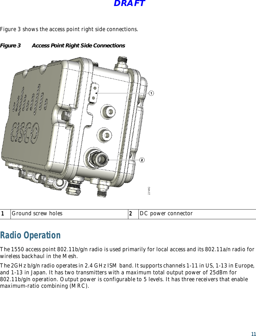
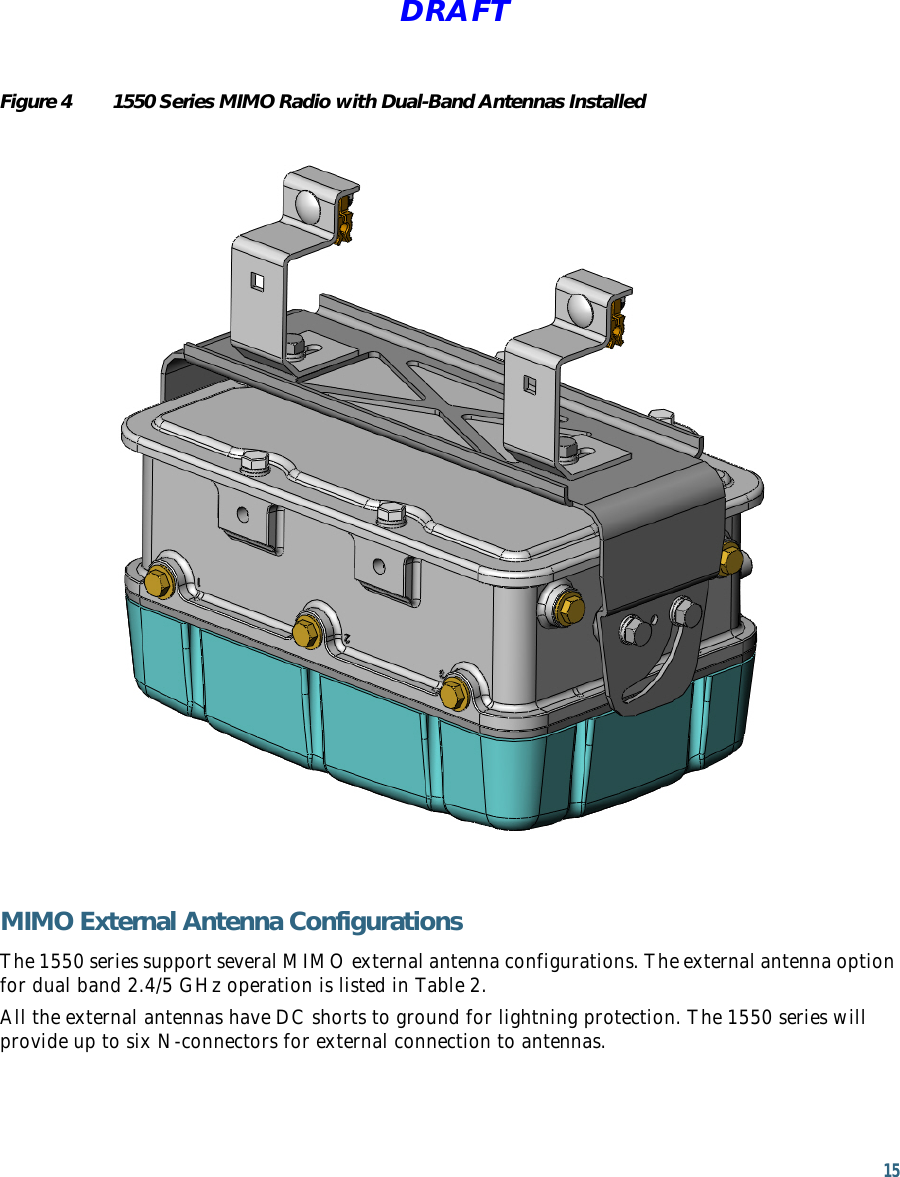
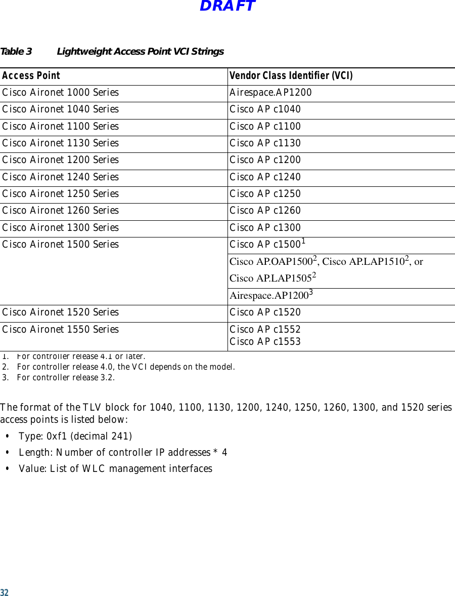
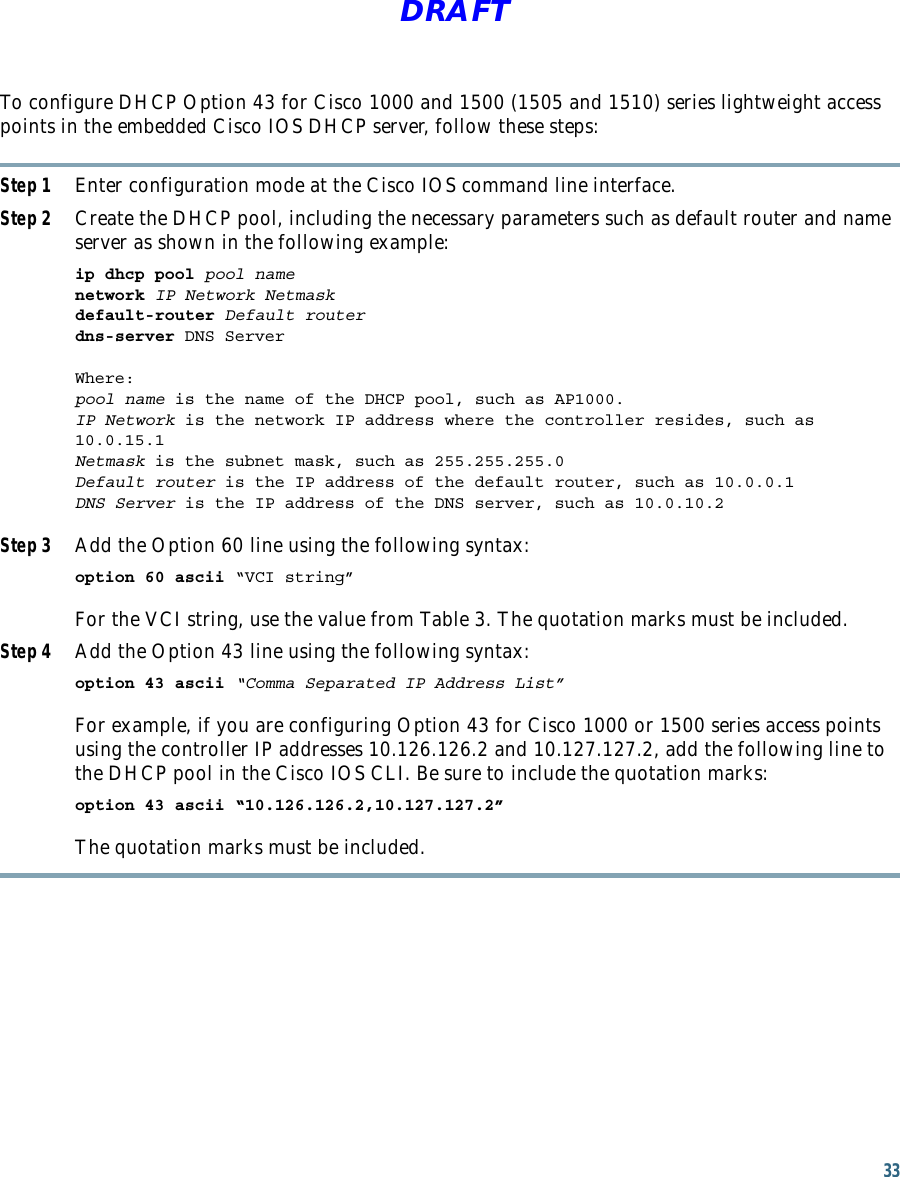
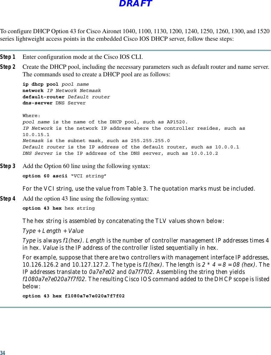
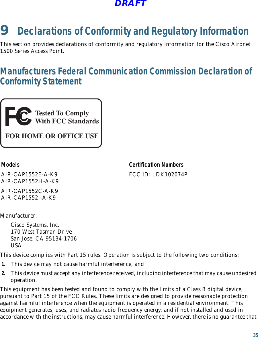
![27 DRAFT • Cable the radios together using a combination of attenuators, combiners, or splitters to achieve a total attenuation of at least 60 dB.For a radiated test bed, the following equation describes the relationships among transmit power, antenna gain, attenuation, and receiver sensitivity:txpwr + tx gain + rx gain - [attenuation due to antenna spacing] < max rx input levelWhere:txpwr = Radio transmit power leveltx gain = transmitter antenna gainrx gain = receiver antenna gainFor a conducted test bed, the following equation describes the relationships among transmit power, antenna gain, and receiver sensitivity:txpwr - [attenuation due to coaxial components] < max rx input levelCaution Under no circumstances should you connect the antenna port from one access point to the antenna port of another access point without using an RF attenuator. If you connect antenna ports you must not exceed the maximum survivable receive level of 0 dBm. Never exceed 0 dBm or damage to the access point can occur. Using attenuators, combiners, and splitters having a total of at least 60 dB of attenuation ensures that the receiver is not damaged and PER performance is not degraded.Before You BeginWarningRead the installation instructions before connecting the system to the power source. Statement 1004Before you begin the installation process: • Become familiar with the procedures for mounting the access point. • Become familiar with the access point connections (Figure 1 on page 9, Figure 2 on page 10, and Figure 3 on page 11). • Verify that the switch you are using to connect the controller is configured properly.](https://usermanual.wiki/Cisco-Systems/102074P.User-manual/User-Guide-1418442-Page-27.png)