Cisco Systems 102087P Cisco Aironet 802.11ac Dual Band Access Points User Manual Wireless LAN Controller Configuration Guide Part2
Cisco Systems Inc Cisco Aironet 802.11ac Dual Band Access Points Wireless LAN Controller Configuration Guide Part2
Contents
- 1. Manual
- 2. revised manual
- 3. Wireless LAN Controller Configuration Guide_Part1
- 4. Wireless LAN Controller Configuration Guide_Part2
- 5. Wireless LAN Controller Configuration Guide_Part3
- 6. Wireless LAN Controller Configuration Guide_Part4
Wireless LAN Controller Configuration Guide_Part2

CHAPTER 27
Configuring the Management Interface
•Information About the Management Interface, page 295
•Configuring the Management Interface (GUI), page 296
•Configuring the Management Interface (CLI), page 297
Information About the Management Interface
The management interface is the default interface for in-band management of the controller and connectivity
to enterprise services such as AAA servers. It is also used for communications between the controller and
access points. The management interface has the only consistently “pingable”in-band interface IP address on
the controller. You can access the GUI of the controller by entering the management interface IP address of
the controller in the address field of either Internet Explorer or Mozilla Firefox browser.
For CAPWAP, the controller requires one management interface to control all inter-controller communications
and one AP-manager interface to control all controller-to-access point communications, regardless of the
number of ports.
To prevent or block a wired or wireless client from accessing the management network on a controller
(from the wireless client dynamic interface or VLAN), the network administrator must ensure that only
authorized clients gain access to the management network through proper CPU ACLs, or use a firewall
between the client dynamic interface and the management network.
Note
Do not map a guest WLAN to the management interface. If the EoIP tunnel breaks, the client could obtain
an IP and be placed on the management subnet.
Caution
Do not configure wired clients in the same VLAN or subnet of the service port of the controller on the
network. If you configure wired clients on the same subnet or VLAN as the service port, it is not possible
to access the management interface of the controller.
Caution
Cisco Wireless LAN Controller Configuration Guide, Release 7.4
OL-28744-01 295

Configuring the Management Interface (GUI)
Step 1 Choose Controller > Interfaces to open the Interfaces page.
Step 2 Click the management link.
The Interfaces > Edit page appears.
Step 3 Set the management interface parameters:
The management interface uses the controller’s factory-set distribution system MAC address.
Note
•Quarantine and quarantine VLAN ID, if applicable
Select the Quarantine check box if you want to configure this VLAN as unhealthy or you want to configure
network access control (NAC) out-of-band integration. Doing so causes the data traffic of any client that
is assigned to this VLAN to pass through the controller.
Note
•NAT address (only Cisco 2500 Series Controllers and Cisco 5500 Series Controllers are configured for dynamic
AP management.)
Select the Enable NAT Address check box and enter the external NAT IP address if you want to be able
to deploy your Cisco 2500 Series Controllers or Cisco 5500 Series Controller behind a router or other
gateway device that is using one-to-one mapping network address translation (NAT). NAT allows a device,
such as a router, to act as an agent between the Internet (public) and a local network (private). In this case,
it maps the controller’s intranet IP addresses to a corresponding external address. The controller’s dynamic
AP-manager interface must be configured with the external NAT IP address so that the controller can send
the correct IP address in the Discovery Response.
Note
If a Cisco 2500 Series Controllers or Cisco 5500 Series Controller is configured with an external NAT IP
address under the management interface, the APs in local mode cannot associate with the controller. The
workaround is to either ensure that the management interface has a globally valid IP address or ensure
that external NAT IP address is valid internally for the local APs.
Note
The NAT parameters are supported for use only with one-to-one-mapping NAT, where each private client
has a direct and fixed mapping to a global address. The NAT parameters do not support one-to-many NAT,
which uses source port mapping to enable a group of clients to be represented by a single IP address.
Note
•VLAN identifier
Enter 0 for an untagged VLAN or a nonzero value for a tagged VLAN. We recommend using tagged
VLANs for the management interface.
Note
•Fixed IP address, IP netmask, and default gateway
•Dynamic AP management (for Cisco 2500 Series Controllers or Cisco 5500 Series Controller only)
For Cisco 5500 Series Controllers, the management interface acts like an AP-manager interface by default.
If desired, you can disable the management interface as an AP-manager interface and create another
dynamic interface as an AP manager.
Note
•Physical port assignment (for all controllers except the Cisco 2500 Series Controllers or Cisco 5500 Series Controller)
•Primary and secondary DHCP servers
•Access control list (ACL) setting, if required
Cisco Wireless LAN Controller Configuration Guide, Release 7.4
296 OL-28744-01
Configuring the Management Interface (GUI)

Step 4 Click Save Configuration.
Step 5 If you made any changes to the management or virtual interface, reboot the controller so that your changes take effect.
Configuring the Management Interface (CLI)
Step 1 Enter the show interface detailed management command to view the current management interface settings.
The management interface uses the controller’s factory-set distribution system MAC address.
Note
Step 2 Enter the config wlan disable wlan-number command to disable each WLAN that uses the management interface for
distribution system communication.
Step 3 Enter these commands to define the management interface:
•config interface address management ip-addr ip-netmask gateway
•config interface quarantine vlan management vlan_id
Use the config interface quarantine vlan management vlan_id command to configure a quarantine
VLAN on the management interface.
Note
•config interface vlan management {vlan-id |0}
Enter 0 for an untagged VLAN or a nonzero value for a tagged VLAN. We recommend using tagged
VLANs for the management interface.
Note
•config interface ap-manager management {enable |disable} (for Cisco 5500 Series Controllers only)
Use the config interface ap-manager management {enable |disable} command to enable or disable
dynamic AP management for the management interface. For Cisco 5500 Series Controllers, the management
interface acts like an AP-manager interface by default. If desired, you can disable the management interface
as an AP-manager interface and create another dynamic interface as an AP manager.
Note
•config interface port management physical-ds-port-number (for all controllers except the 5500 series)
•config interface dhcp management ip-address-of-primary-dhcp-server [ip-address-of-secondary-dhcp-server]
•config interface acl management access-control-list-name
Step 4 Enter these commands if you want to be able to deploy your Cisco 5500 Series Controller behind a router or other gateway
device that is using one-to-one mapping network address translation (NAT):
•config interface nat-address management {enable |disable}
•config interface nat-address management set public_IP_address
NAT allows a device, such as a router, to act as an agent between the Internet (public) and a local network (private). In
this case, it maps the controller’s intranet IP addresses to a corresponding external address. The controller’s dynamic
AP-manager interface must be configured with the external NAT IP address so that the controller can send the correct
IP address in the Discovery Response.
Cisco Wireless LAN Controller Configuration Guide, Release 7.4
OL-28744-01 297
Configuring the Management Interface (CLI)

These commands are supported for use only with one-to-one-mapping NAT, where each private client has a
direct and fixed mapping to a global address. These commands do not support one-to-many NAT, which uses
source port mapping to enable a group of clients to be represented by a single IP address.
Note
Step 5 Enter the save config command.
Step 6 Enter the show interface detailed management command to verify that your changes have been saved.
Step 7 If you made any changes to the management interface, enter the reset system command to reboot the controller in order
for the changes to take effect.
Cisco Wireless LAN Controller Configuration Guide, Release 7.4
298 OL-28744-01
Configuring the Management Interface (CLI)

CHAPTER 28
Configuring the AP-Manager Interface
•Information the About AP-Manager Interface, page 299
•Restrictions for Configuring AP Manager Interfaces, page 299
•Configuring the AP-Manager Interface (GUI), page 300
•Configuring the AP Manager Interface (CLI), page 300
•Configuration Example: Configuring AP-Manager on a Cisco 5500 Series Controller, page 301
Information the About AP-Manager Interface
A controller has one or more AP-manager interfaces, which are used for all Layer 3 communications between
the controller and lightweight access points after the access points have joined the controller. The AP-manager
IP address is used as the tunnel source for CAPWAP packets from the controller to the access point and as
the destination for CAPWAP packets from the access point to the controller.
The controller does not support transmitting the jumbo frames. To avoid having the controller transmit
CAPWAP packets to the AP that will necessitate fragmentation and reassembly, reduce MTU/MSS on
the client side.
Note
The AP-manager interface communicates through any distribution system port by listening across the Layer
3 network for access point CAPWAP or LWAPP join messages to associate and communicate with as many
lightweight access points as possible.
Restrictions for Configuring AP Manager Interfaces
•The MAC address of the management interface and the AP-manager interface is the same as the base
LAG MAC address.
•If only one distribution system port can be used, you should use distribution system port 1.
•
Cisco Wireless LAN Controller Configuration Guide, Release 7.4
OL-28744-01 299

•An AP-manager interface is not required to be configured. The management interface acts like an
AP-manager interface by default, and the access points can join on this interface.
•If link aggregation (LAG) is enabled, there can be only one AP-manager interface. But when LAG is
disabled, one or more AP-manager interfaces can be created, generally one per physical port.
•Port redundancy for the AP-manager interface is not supported. You cannot map the AP-manager
interface to a backup port.
Configuring the AP-Manager Interface (GUI)
Step 1 Choose Controller > Interfaces to open the Interfaces page.
Step 2 Click AP-Manager Interface.
The Interface > Edit page appears.
Step 3 Set the AP-Manager Interface parameters:
For Cisco 5500 Series Controllers, you are not required to configure an AP-manager interface. The management
interface acts like an AP-manager interface by default.
Note
•Physical port assignment
•VLAN identifier
Enter 0 for an untagged VLAN or a nonzero value for a tagged VLAN. We recommend using tagged
VLANs for the AP-manager interface.
Note
•Fixed IP address, IP netmask, and default gateway
•Primary and secondary DHCP servers
•Access control list (ACL) name, if required
Step 4 Click Save Configuration to save your changes.
Step 5 If you made any changes to the management or virtual interface, reboot the controller so that your changes take effect.
Configuring the AP Manager Interface (CLI)
Before You Begin
For Cisco 5500 Series Controllers, you are not required to configure an AP-manager interface. The management
interface acts like an AP-manager interface by default.
Step 1 Enter the show interface summary command to view the current interfaces.
If the system is operating in Layer 2 mode, the AP-manager interface is not
listed.
Note
Cisco Wireless LAN Controller Configuration Guide, Release 7.4
300 OL-28744-01
Configuring the AP-Manager Interface (GUI)

Step 2 Enter the show interface detailed ap-manager command to view the current AP-manager interface settings.
Step 3 Enter the config wlan disable wlan-number command to disable each WLAN that uses the AP-manager interface for
distribution system communication.
Step 4 Enter these commands to define the AP-manager interface:
•config interface address ap-manager ip-addr ip-netmask gateway
•config interface vlan ap-manager {vlan-id |0}
Enter 0for an untagged VLAN or a nonzero value for a tagged VLAN. We recommend using tagged
VLANs for the AP-manager interface.
Note
•config interface port ap-manager physical-ds-port-number
•config interface dhcp ap-manager ip-address-of-primary-dhcp-server [ip-address-of-secondary-dhcp-server]
•config interface acl ap-manager access-control-list-name
Step 5 Enter the save config command to save your changes.
Step 6 Enter the show interface detailed ap-manager command to verify that your changes have been saved.
Configuration Example: Configuring AP-Manager on a Cisco 5500 Series
Controller
For a Cisco 5500 Series Controller, we recommend that you have eight dynamic AP-manager interfaces and
associate them to the eight Gigabit ports of the controller when LAG is not used. If you are using the
management interface, which acts like an AP-manager interface by default, you must create only seven more
dynamic AP-manager interfaces and associate them to the remaining seven Gigabit ports.
Cisco Wireless LAN Controller Configuration Guide, Release 7.4
OL-28744-01 301
Configuration Example: Configuring AP-Manager on a Cisco 5500 Series Controller
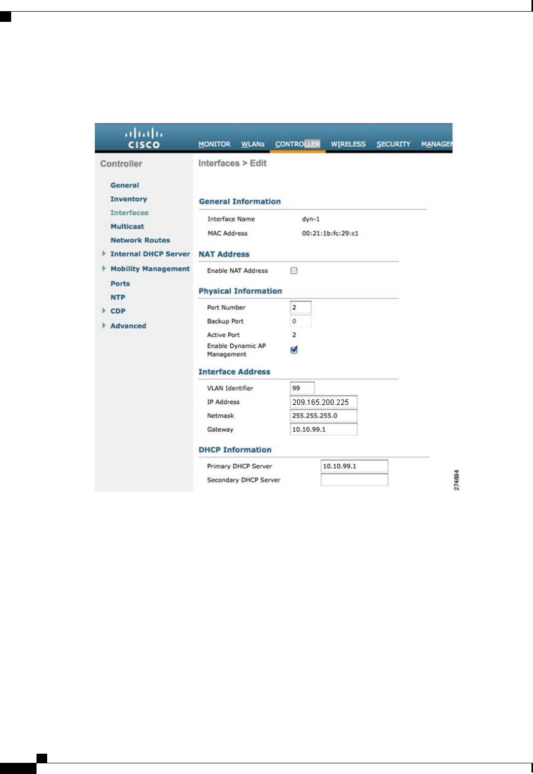
This figure shows a dynamic interface that is enabled as a dynamic AP-manager interface and associated to
port number 2.
Figure 35: Dynamic Interface Example with Dynamic AP Management
Cisco Wireless LAN Controller Configuration Guide, Release 7.4
302 OL-28744-01
Configuration Example: Configuring AP-Manager on a Cisco 5500 Series Controller
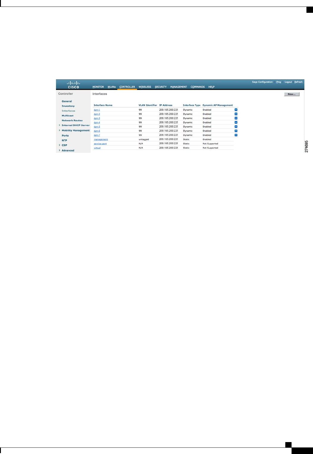
This figure shows a Cisco 5500 Series Controller with LAG disabled, the management interface used as one
dynamic AP-manager interface, and seven additional dynamic AP-manager interfaces, each mapped to a
different Gigabit port.
Figure 36: Cisco 5500 Series Controller Interface Configuration Example
Cisco Wireless LAN Controller Configuration Guide, Release 7.4
OL-28744-01 303
Configuration Example: Configuring AP-Manager on a Cisco 5500 Series Controller

Cisco Wireless LAN Controller Configuration Guide, Release 7.4
304 OL-28744-01
Configuration Example: Configuring AP-Manager on a Cisco 5500 Series Controller

CHAPTER 29
Configuring Virtual Interfaces
•Information About the Virtual Interface, page 305
•Configuring Virtual Interfaces (GUI), page 306
•Configuring Virtual Interfaces (CLI), page 306
Information About the Virtual Interface
The virtual interface is used to support mobility management, Dynamic Host Configuration Protocol (DHCP)
relay, and embedded Layer 3 security such as guest web authentication and VPN termination. It also maintains
the DNS gateway host name used by Layer 3 security and mobility managers to verify the source of certificates
when Layer 3 web authorization is enabled.
Specifically, the virtual interface plays these two primary roles:
•Acts as the DHCP server placeholder for wireless clients that obtain their IP address from a DHCP
server.
•Serves as the redirect address for the web authentication login page.
The virtual interface IP address is used only in communications between the controller and wireless clients.
It never appears as the source or destination address of a packet that goes out a distribution system port and
onto the switched network. For the system to operate correctly, the virtual interface IP address must be set (it
cannot be 0.0.0.0), and no other device on the network can have the same address as the virtual interface.
Therefore, the virtual interface must be configured with an unassigned and unused gateway IP address. The
virtual interface IP address is not pingable and should not exist in any routing table in your network. In addition,
the virtual interface cannot be mapped to a physical port.
All controllers within a mobility group must be configured with the same virtual interface IP address.
Otherwise, inter-controller roaming may appear to work, but the handoff does not complete, and the client
loses connectivity for a period of time.
Note
Cisco Wireless LAN Controller Configuration Guide, Release 7.4
OL-28744-01 305

Configuring Virtual Interfaces (GUI)
Step 1 Choose Controller > Interfaces to open the Interfaces page.
Step 2 Click Virtual.
The Interfaces > Edit page appears.
Step 3 Enter the following parameters:
•Any fictitious, unassigned, and unused gateway IP address
•DNS gateway hostname
To ensure connectivity and web authentication, the DNS server should always point to the virtual interface.
If a DNS hostname is configured for the virtual interface, then the same DNS host name must be configured
on the DNS server(s) used by the client.
Note
Step 4 Click Save Configuration.
Step 5 If you made any changes to the management or virtual interface, reboot the controller so that your changes take effect.
Configuring Virtual Interfaces (CLI)
Step 1 Enter the show interface detailed virtual command to view the current virtual interface settings.
Step 2 Enter the config wlan disable wlan-number command to disable each WLAN that uses the virtual interface for distribution
system communication.
Step 3 Enter these commands to define the virtual interface:
•config interface address virtual ip-address
For ip-address, enter any fictitious, unassigned, and unused gateway IP address.
Note
•config interface hostname virtual dns-host-name
Step 4 Enter the reset system command. At the confirmation prompt, enter Y to save your configuration changes to NVRAM.
The controller reboots.
Step 5 Enter the show interface detailed virtual command to verify that your changes have been saved.
Cisco Wireless LAN Controller Configuration Guide, Release 7.4
306 OL-28744-01
Configuring Virtual Interfaces (GUI)

CHAPTER 30
Configuring Service-Port Interfaces
•Information About Service-Port Interfaces, page 307
•Restrictions for Configuring Service-Port Interfaces, page 307
•Configuring Service-Port Interfaces (GUI), page 307
•Configuring Service-Port Interfaces (CLI), page 308
Information About Service-Port Interfaces
The service-port interface controls communications through and is statically mapped by the system to the
service port. The service port can obtain an IP address using DHCP, or it can be assigned a static IP address,
but a default gateway cannot be assigned to the service-port interface. Static routes can be defined through
the controller for remote network access to the service port.
Restrictions for Configuring Service-Port Interfaces
•Only Cisco 7500 Series Controllers and Cisco 5500 Series Controllers have a physical service-port
interface that is reachable from the external network.
Configuring Service-Port Interfaces (GUI)
Step 1 Choose Controller >Interfaces to open the Interfaces page.
Step 2 Click the service-port link to open the Interfaces > Edit page.
Step 3 Enter the Service-Port Interface parameters:
The service-port interface uses the controller’s factory-set service-port MAC address.
Note
•DHCP protocol (enabled)
•DHCP protocol (disabled) and IP address and IP netmask
Cisco Wireless LAN Controller Configuration Guide, Release 7.4
OL-28744-01 307

Step 4 Click Save Configuration to save your changes.
Step 5 If you made any changes to the management or virtual interface, reboot the controller so that your changes take effect.
Configuring Service-Port Interfaces (CLI)
Step 1 To view the current service-port interface settings, enter this command:
show interface detailed service-port
The service-port interface uses the controller’s factory-set service-port MAC address.
Note
Step 2 Enter these commands to define the service-port interface:
•To configure the DHCP server, enter this command:
config interface dhcp service-port enable
•To disable the DHCP server, enter this command:
config interface dhcp service-port disable
•To configure the IP address, enter this command:
config interface address service-port ip-addr ip-netmask
Step 3 The service port is used for out-of-band management of the controller. If the management workstation is in a remote
subnet, you may need to add a route on the controller in order to manage the controller from that remote workstation.
To do so, enter this command:
config route add network-ip-addr ip-netmask gateway
Step 4 Enter the save config command to save your changes.
Step 5 Enter the show interface detailed service-port command to verify that your changes have been saved.
Cisco Wireless LAN Controller Configuration Guide, Release 7.4
308 OL-28744-01
Configuring Service-Port Interfaces (CLI)

CHAPTER 31
Configuring Dynamic Interfaces
•Information About Dynamic Interface, page 309
•Pre - requisites for Configuring Dynamic Interfaces, page 310
•Restrictions for Configuring Dynamic Interfaces, page 310
•Configuring Dynamic Interfaces (GUI), page 310
•Configuring Dynamic Interfaces (CLI), page 312
Information About Dynamic Interface
Dynamic interfaces, also known as VLAN interfaces, are created by users and designed to be analogous to
VLANs for wireless LAN clients. A controller can support up to 512 dynamic interfaces (VLANs). Each
dynamic interface is individually configured and allows separate communication streams to exist on any or
all of a controller’s distribution system ports. Each dynamic interface controls VLANs and other communications
between controllers and all other network devices, and each acts as a DHCP relay for wireless clients associated
to WLANs mapped to the interface. You can assign dynamic interfaces to distribution system ports, WLANs,
the Layer 2 management interface, and the Layer 3 AP-manager interface, and you can map the dynamic
interface to a backup port.
You can configure zero, one, or multiple dynamic interfaces on a distribution system port. However, all
dynamic interfaces must be on a different VLAN or IP subnet from all other interfaces configured on the port.
If the port is untagged, all dynamic interfaces must be on a different IP subnet from any other interface
configured on the port.
This table lists the maximum number of VLANs supported on the various controller platforms.
Table 7: Maximum number of VLANs supported on Cisco Wireless Controllers
Maximum VLANsWireless Controllers
512Cisco Virtual Wireless Controller
16Cisco Wireless Controller Module for ISR G2
16Cisco 2500 Series Wireless Controllers
Cisco Wireless LAN Controller Configuration Guide, Release 7.4
OL-28744-01 309

Maximum VLANsWireless Controllers
512Cisco 5500 Series Wireless Controller
512Cisco Catalyst 6500 Series Wireless Services
Module2 (WiSM2)
4,096Cisco Flex 7500 Series Cloud Controller
4,096Cisco 8500 Series Controller
Pre - requisites for Configuring Dynamic Interfaces
While configuring on the dynamic interface of the controller, you must ensure the following:
•
•You must use tagged VLANs for dynamic interfaces.
Restrictions for Configuring Dynamic Interfaces
The following restrictions apply for configuring the dynamic interfaces on the controller:
•You must not configure a dynamic interface in the same subnetwork as a server that is reachable by the
controller CPU, such as a RADIUS server, as it might cause asymmetric routing issues.
•Wired clients cannot access management interface of the Cisco WLC 2500 series using the IP address
of the AP Manager interface –when Dynamic AP Management is enabled on a dynamic VLAN.
•
•For SNMP requests that come from a subnet that is configured as a dynamic interface, the controller
responds but the response does not reach the device that initiated the conversation.
•If you are using DHCP proxy and/or a RADIUS source interface, ensure that the dynamic interface has
a valid routable address. Duplicate or overlapping addresses across controller interfaces are not supported.
Configuring Dynamic Interfaces (GUI)
Step 1 Choose Controller > Interfaces to open the Interfaces page.
Step 2 Perform one of the following:
•To create a new dynamic interface, click New. The Interfaces > New page appears. Go to Step 3.
•To modify the settings of an existing dynamic interface, click the name of the interface. The Interfaces > Edit
page for that interface appears. Go to Step 5.
Cisco Wireless LAN Controller Configuration Guide, Release 7.4
310 OL-28744-01
Pre - requisites for Configuring Dynamic Interfaces

•To delete an existing dynamic interface, hover your cursor over the blue drop-down arrow for the desired interface
and choose Remove.
Step 3 Enter an interface name and a VLAN identifier, as shown in the figure above.
Step 4 Click Apply to commit your changes. The Interfaces > Edit page appears.
Step 5 Configure the following parameters:
•Guest LAN, if applicable
•Quarantine and quarantine VLAN ID, if applicable
Select the Quarantine check box if you want to configure this VLAN as unhealthy or you want to configure
network access control (NAC) out-of-band integration. Doing so causes the data traffic of any client that
is assigned to this VLAN to pass through the controller.
Note
•Physical port assignment (for all controllers except the 5500 series)
•NAT address (only for Cisco 5500 Series Controllers configured for dynamic AP management)
Select the Enable NAT Address check box and enter the external NAT IP address if you want to be able
to deploy your Cisco 5500 Series Controller behind a router or other gateway device that is using one-to-one
mapping network address translation (NAT). NAT allows a device, such as a router, to act as an agent
between the Internet (public) and a local network (private). In this case, it maps the controller’s intranet
IP addresses to a corresponding external address. The controller’s dynamic AP-manager interface must
be configured with the external NAT IP address so that the controller can send the correct IP address in
the Discovery Response.
Note
The NAT parameters are supported for use only with one-to-one-mapping NAT, where each private client
has a direct and fixed mapping to a global address. The NAT parameters do not support one-to-many NAT,
which uses source port mapping to enable a group of clients to be represented by a single IP address.
Note
•Dynamic AP management
When you enable this feature, this dynamic interface is configured as an AP-manager interface (only one
AP-manager interface is allowed per physical port). A dynamic interface that is marked as an AP-manager
interface cannot be used as a WLAN interface.
Note
Set the APs in a VLAN that is different than the dynamic interface configured on the controller. If the APs
are in the same VLAN as the dynamic interface, the APs are not registered on the controller and the
“LWAPP discovery rejected”and “Layer 3 discovery request not received on management VLAN”errors
are logged on the controller.
Note
•VLAN identifier
•Fixed IP address, IP netmask, and default gateway
•Primary and secondary DHCP servers
•Access control list (ACL) name, if required
To ensure proper operation, you must set the Port Number and Primary DHCP Server parameters.Note
Step 6 Click Save Configuration to save your changes.
Step 7 Repeat this procedure for each dynamic interface that you want to create or edit.
Cisco Wireless LAN Controller Configuration Guide, Release 7.4
OL-28744-01 311
Configuring Dynamic Interfaces (GUI)

Configuring Dynamic Interfaces (CLI)
Step 1 Enter the show interface summary command to view the current dynamic interfaces.
Step 2 View the details of a specific dynamic interface by entering this command:
show interface detailed operator_defined_interface_name.
Interface names that contain spaces must be enclosed in double quotes. For example: config interface create
"vlan 25"
Note
Step 3 Enter the config wlan disable wlan_id command to disable each WLAN that uses the dynamic interface for distribution
system communication.
Step 4 Enter these commands to configure dynamic interfaces:
•config interface create operator_defined_interface_name {vlan_id |x}
•config interface address interface ip_addr ip_netmask [gateway]
•config interface vlan operator_defined_interface_name {vlan_id |o}
•config interface port operator_defined_interface_name physical_ds_port_number
•config interface ap-manager operator_defined_interface_name {enable |disable}
Use the config interface ap-manager operator_defined_interface_name {enable |disable} command
to enable or disable dynamic AP management. When you enable this feature, this dynamic interface is
configured as an AP-manager interface (only one AP-manager interface is allowed per physical port). A
dynamic interface that is marked as an AP-manager interface cannot be used as a WLAN interface.
Note
•config interface dhcp operator_defined_interface_name ip_address_of_primary_dhcp_server
[ip_address_of_secondary_dhcp_server]
•config interface quarantine vlan interface_name vlan_id
Use the config interface quarantine vlan interface_name vlan_id command to configure a quarantine
VLAN on any interface.
Note
•config interface acl operator_defined_interface_name access_control_list_name
Step 5 Enter these commands if you want to be able to deploy your Cisco 5500 Series Controller behind a router or other gateway
device that is using one-to-one mapping network address translation (NAT):
•config interface nat-address dynamic-interface operator_defined_interface_name {enable |disable}
•config interface nat-address dynamic-interface operator_defined_interface_name set public_IP_address
NAT allows a device, such as a router, to act as an agent between the Internet (public) and a local network (private). In
this case, it maps the controller’s intranet IP addresses to a corresponding external address. The controller’s dynamic
AP-manager interface must be configured with the external NAT IP address so that the controller can send the correct
IP address in the Discovery Response.
These commands are supported for use only with one-to-one-mapping NAT, whereby each private client has a
direct and fixed mapping to a global address. These commands do not support one-to-many NAT, which uses
source port mapping to enable a group of clients to be represented by a single IP address.
Note
Cisco Wireless LAN Controller Configuration Guide, Release 7.4
312 OL-28744-01
Configuring Dynamic Interfaces (CLI)

Step 6 Enter the config wlan enable wlan_id command to reenable each WLAN that uses the dynamic interface for distribution
system communication.
Step 7 Enter the save config command to save your changes.
Step 8 Enter the show interface detailed operator_defined_interface_name command and show interface summary command
to verify that your changes have been saved.
If desired, you can enter the config interface delete operator_defined_interface_name command to delete a
dynamic interface.
Note
Cisco Wireless LAN Controller Configuration Guide, Release 7.4
OL-28744-01 313
Configuring Dynamic Interfaces (CLI)

Cisco Wireless LAN Controller Configuration Guide, Release 7.4
314 OL-28744-01
Configuring Dynamic Interfaces (CLI)

CHAPTER 32
Configuring Ports
•Configuring Ports (GUI), page 315
Configuring Ports (GUI)
The controller’s ports are configured with factory-default settings designed to make the controllers’ports
operational without additional configuration. However, you can view the status of the controller’s ports and
edit their configuration parameters at any time.
Step 1 Choose Controller >Ports to open the Ports page.
This page shows the current configuration for each of the controller’s ports.
If you want to change the settings of any port, click the number for that specific port. The Port > Configure page appears.
If the management and AP-manager interfaces are mapped to the same port and are members of the same VLAN,
you must disable the WLAN before making a port-mapping change to either interface. If the management and
AP-manager interfaces are assigned to different VLANs, you do not need to disable the WLAN.
Note
The number of parameters available on the Port > Configure page depends on your controller
type.
Note
The following show the current status of the port:
•Port Number—Number of the current port.
•Admin Status—Current state of the port. Values: Enable or Disable
•Physical Mode—Configuration of the port physical interface. The mode varies by the controller type.
•Physical Status—The data rate being used by the port. The available data rates vary based on controller type.
◦2500 series - 1 Gbps full duplex
◦WiSM2 - 10 Gbps full duplex
◦7500 series - 10 Gbps full duplex
•Link Status—Link status of the port. Values: Link Up or Link Down
Cisco Wireless LAN Controller Configuration Guide, Release 7.4
OL-28744-01 315

•Link Trap—Whether the port is set to send a trap when the link status changes. Values: Enable or Disable
•Power over Ethernet (PoE)—If the connecting device is equipped to receive power through the Ethernet cable and
if so, provides –48 VDC. Values: Enable or Disable
Some older Cisco access points do not draw PoE even if it is enabled on the controller port. In such cases,
contact the Cisco Technical Assistance Center (TAC).
Note
The following is a list of the port’s configurable parameters.
1Admin Status—Enables or disables the flow of traffic through the port. Options: Enable or Disable Default: Enable.
When a primary port link goes down, messages may get logged internally only and not be posted to a syslog
server. It may take up to 40 seconds to restore logging to the syslog server.
Note
2Physical Mode—Determines whether the port’s data rate is set automatically or specified by the user. The supported
data rates vary based on the controller type. Default: Auto.
3Link Trap—Causes the port to send a trap when the port’s link status changes. Options: Enable or Disable Default:
Enable.
Step 2 Click Apply.
Step 3 Click Save Configuration.
Step 4 Click Back to return to the Ports page and review your changes.
Step 5 Repeat this procedure for each additional port that you want to configure.
Cisco Wireless LAN Controller Configuration Guide, Release 7.4
316 OL-28744-01
Configuring Ports (GUI)

CHAPTER 33
Information About Using Cisco 5500 Series
Controller USB Console Port
The USB console port on the Cisco 5500 Series Controllers connects directly to the USB connector of a PC
using a USB Type A-to-5-pin mini Type B cable.
The 4-pin mini Type B connector is easily confused with the 5-pin mini Type B connector. They are not
compatible. Only the 5-pin mini Type B connector can be used.
Note
For operation with Microsoft Windows, the Cisco Windows USB console driver must be installed on any
PC connected to the console port. With this driver, you can plug and unplug the USB cable into and from
the console port without affecting Windows HyperTerminal operations.
Only one console port can be active at a time. When a cable is plugged into the USB console port, the
RJ-45 port becomes inactive. Conversely, when the USB cable is removed from the USB port, the RJ-45
port becomes active.
Note
•USB Console OS Compatibility, page 317
•Changing the Cisco USB Systems Management Console COM Port to an Unused Port, page 318
USB Console OS Compatibility
Before You Begin
These operating systems are compatible with the USB console:
•Microsoft Windows 2000, Windows XP, Windows Vista, Windows 7 (Cisco Windows USB console
driver required)
•Apple Mac OS X 10.5.2 (no driver required)
Cisco Wireless LAN Controller Configuration Guide, Release 7.4
OL-28744-01 317

•Linux (no driver required)
Step 1 Download the USB_Console.inf driver file as follows:
a) Click this URL to go to the Software Center: http://tools.cisco.com/support/downloads/go/Redirect.x?mdfid=278875243
b) Click Wireless LAN Controllers.
c) Click Standalone Controllers.
d) Click Cisco 5500 Series Wireless LAN Controllers.
e) Click Cisco 5508 Wireless LAN Controller.
f) Choose the USB driver file.
g) Save the file to your hard drive.
Step 2 Connect the Type A connector to a USB port on your PC.
Step 3 Connect the mini Type B connector to the USB console port on the controller.
Step 4 When prompted for a driver, browse to the USB_Console.inf file on your PC. Follow the prompts to install the USB
driver.
Some systems might also require an additional system file. You can download the Usbser.sys file from http://
support.microsoft.com/kb/918365.
Note
Changing the Cisco USB Systems Management Console COM Port to an Unused
Port
Before You Begin
The USB driver is mapped to COM port 6. Some terminal emulation programs do not recognize a port higher
than COM 4. If necessary, you must change the Cisco USB systems management console COM port to an
unused port of COM 4 or lower.
Step 1 From your Windows desktop, right-click My Computer and choose Manage.
Step 2 From the list on the left side, choose Device Manager.
Step 3 From the device list on the right side, double-click Ports (COM & LPT).
Step 4 Right-click Cisco USB System Management Console 0108 and choose Properties.
Step 5 Click the Port Settings tab and click the Advanced button.
Step 6 From the COM Port Number drop-down list, choose an unused COM port of 4 or lower.
Step 7 Click OK to save and then close the Advanced Settings dialog box.
Step 8 Click OK to save and then close the Communications Port Properties dialog box.
Cisco Wireless LAN Controller Configuration Guide, Release 7.4
318 OL-28744-01
Changing the Cisco USB Systems Management Console COM Port to an Unused Port

CHAPTER 34
Configuring Link Aggregation
•Information About Link Aggregation, page 319
•Restrictions for Link Aggregation, page 319
•Enabling Link Aggregation (GUI), page 321
•Enabling Link Aggregation (CLI), page 321
•Verifying Link Aggregation Settings (CLI), page 322
•Configuring Neighbor Devices to Support Link Aggregation, page 322
•Choosing Between Link Aggregation and Multiple AP-Manager Interfaces, page 322
Information About Link Aggregation
Link aggregation (LAG) is a partial implementation of the 802.3ad port aggregation standard. It bundles all
of the controller’s distribution system ports into a single 802.3ad port channel, thereby reducing the number
of IP addresses needed to configure the ports on your controller. When LAG is enabled, the system dynamically
manages port redundancy and load balances access points transparently to the user.
LAG simplifies controller configuration because you no longer need to configure primary and secondary ports
for each interface. If any of the controller ports fail, traffic is automatically migrated to one of the other ports.
As long as at least one controller port is functioning, the system continues to operate, access points remain
connected to the network, and wireless clients continue to send and receive data.
LAG is supported across switches.Note
Restrictions for Link Aggregation
•You can bundle all eight ports on a Cisco 5508 Controller into a single link.
•Terminating on two different modules within a single Catalyst 6500 series switch provides redundancy
and ensures that connectivity between the switch and the controller is maintained when one module
fails. The controller’s port 1 is connected to Gigabit interface 3/1, and the controller’s port 2 is connected
Cisco Wireless LAN Controller Configuration Guide, Release 7.4
OL-28744-01 319
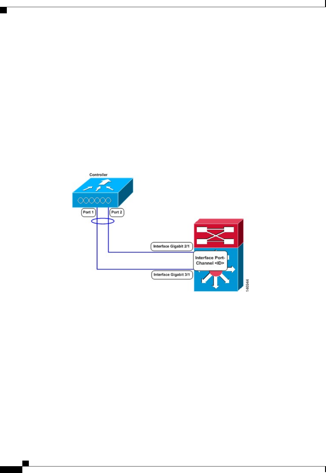
to Gigabit interface 2/1 on the Catalyst 6500 series switch. Both switch ports are assigned to the same
channel group.
•LAG requires the EtherChannel to be configured for 'mode on' on both the controller and the Catalyst
switch.
•Once the EtherChannel is configured as on at both ends of the link, the Catalyst switch should not be
configured for either Link Aggregation Control Protocol (LACP) or Cisco proprietary Port Aggregation
Protocol (PAgP) but be set unconditionally to LAG. Because no channel negotiation is done between
the controller and the switch, the controller does not answer to negotiation frames and the LAG is not
formed if a dynamic form of LAG is set on the switch. Additionally, LACP and PAgP are not supported
on the controller.
•If the recommended load-balancing method cannot be configured on the Catalyst switch, then configure
the LAG connection as a single member link or disable LAG on the controller.
Figure 37: Link Aggregation with the Catalyst 6500 Series Neighbor Switch
•You cannot configure the controller’s ports into separate LAG groups. Only one LAG group is supported
per controller. Therefore, you can connect a controller in LAG mode to only one neighbor device.
•When you enable LAG or make any changes to the LAG configuration, you must immediately reboot
the controller.
•When you enable LAG, you can configure only one AP-manager interface because only one logical port
is needed. LAG removes the requirement for supporting multiple AP-manager interfaces.
•When you enable LAG, all dynamic AP-manager interfaces and untagged interfaces are deleted, and all
WLANs are disabled and mapped to the management interface. Also, the management, static AP-manager,
and VLAN-tagged dynamic interfaces are moved to the LAG port.
•Multiple untagged interfaces to the same port are not allowed.
•When you enable LAG, you cannot create interfaces with a primary port other than 29.
•When you enable LAG, all ports participate in LAG by default. You must configure LAG for all of the
connected ports in the neighbor switch.
Cisco Wireless LAN Controller Configuration Guide, Release 7.4
320 OL-28744-01
Restrictions for Link Aggregation

•When you enable LAG, if any single link goes down, traffic migrates to the other links.
•When you enable LAG, only one functional physical port is needed for the controller to pass client
traffic.
•When you enable LAG, access points remain connected to the controller until you reboot the controller,
which is needed to activate the LAG mode change, and data service for users continues uninterrupted.
•When you enable LAG, you eliminate the need to configure primary and secondary ports for each
interface.
•When you enable LAG, the controller sends packets out on the same port on which it received them. If
a CAPWAP packet from an access point enters the controller on physical port 1, the controller removes
the CAPWAP wrapper, processes the packet, and forwards it to the network on physical port 1. This
may not be the case if you disable LAG.
•When you disable LAG, the management, static AP-manager, and dynamic interfaces are moved to port
1.
•When you disable LAG, you must configure primary and secondary ports for all interfaces.
•When you disable LAG, you must assign an AP-manager interface to each port on the controller.
Otherwise, access points are unable to join.
•Cisco 5500 Series Controllers support a single static link aggregation bundle.
•LAG is typically configured using the Startup Wizard, but you can enable or disable it at any time through
either the GUI or CLI.
•When you enable LAG on Cisco 2500 Series Controller to which the direct-connect access point is
associated, the direct connect access point is disconnected since LAG enabling is still in the transition
state. You must reboot the controller immediately after enabling LAG.
Enabling Link Aggregation (GUI)
Step 1 Choose Controller > General to open the General page.
Step 2 Set the LAG Mode on Next Reboot parameter to Enabled.
Step 3 Click Apply to commit your changes.
Step 4 Click Save Configuration to save your changes.
Step 5 Reboot the controller.
Step 6 Assign the WLAN to the appropriate VLAN.
Enabling Link Aggregation (CLI)
Step 1 Enter the config lag enable command to enable LAG.
Cisco Wireless LAN Controller Configuration Guide, Release 7.4
OL-28744-01 321
Enabling Link Aggregation (GUI)

Enter the config lag disable command if you want to disable
LAG.
Note
Step 2 Enter the save config command to save your settings.
Step 3 Reboot the controller.
Verifying Link Aggregation Settings (CLI)
To verify your LAG settings, enter this command:
show lag summary
Information similar to the following appears:
LAG Enabled
Configuring Neighbor Devices to Support Link Aggregation
The controller’s neighbor devices must also be properly configured to support LAG.
•Each neighbor port to which the controller is connected should be configured as follows:
interface GigabitEthernet <interface id>
switchport
channel-group <id> mode on
no shutdown
•The port channel on the neighbor switch should be configured as follows:
interface port-channel <id>
switchport
switchport trunk encapsulation dot1q
switchport trunk native vlan <native vlan id>
switchport trunk allowed vlan <allowed vlans>
switchport mode trunk
no shutdown
Choosing Between Link Aggregation and Multiple AP-Manager Interfaces
Cisco 5500 Series Controllers have no restrictions on the number of access points per port, but we recommend
using LAG or multiple AP-manager interfaces on each Gigabit Ethernet port to automatically balance the
load.
The following factors should help you decide which method to use if your controller is set for Layer 3 operation:
•With LAG, all of the controller ports need to connect to the same neighbor switch. If the neighbor switch
goes down, the controller loses connectivity.
•With multiple AP-manager interfaces, you can connect your ports to different neighbor devices. If one
of the neighbor switches goes down, the controller still has connectivity. However, using multiple
AP-manager interfaces presents certain challenges when port redundancy is a concern.
Cisco Wireless LAN Controller Configuration Guide, Release 7.4
322 OL-28744-01
Verifying Link Aggregation Settings (CLI)

CHAPTER 35
Configuring Multiple AP-Manager Interfaces
•Information About Multiple AP-Manager Interfaces, page 323
•Restrictions for Configuring Multiple AP Manager Interfaces, page 323
•Creating Multiple AP-Manager Interfaces (GUI), page 324
•Creating Multiple AP-Manager Interfaces (CLI), page 324
Information About Multiple AP-Manager Interfaces
When you create two or more AP-manager interfaces, each one is mapped to a different port. The ports should
be configured in sequential order so that AP-manager interface 2 is on port 2, AP-manager interface 3 is on
port 3, and AP-manager interface 4 is on port 4.
Before an access point joins a controller, it sends out a discovery request. From the discovery response that
it receives, the access point can tell the number of AP-manager interfaces on the controller and the number
of access points on each AP-manager interface. The access point generally joins the AP-manager with the
least number of access points. In this way, the access point load is dynamically distributed across the multiple
AP-manager interfaces.
Access points may not be distributed completely evenly across all of the AP-manager interfaces, but a
certain level of load balancing occurs.
Note
Restrictions for Configuring Multiple AP Manager Interfaces
The following restrictions apply while configuring the multiple AP manager interfaces in the controller:
•You must assign an AP-manager interface to each port on the controller.
•Before implementing multiple AP-manager interfaces, you should consider how they would impact your
controller’s port redundancy.
•Only Cisco 5500 Series Controllers support the use of multiple AP-manager interfaces.
Cisco Wireless LAN Controller Configuration Guide, Release 7.4
OL-28744-01 323

•AP-manager interfaces do not need to be on the same VLAN or IP subnet, and they may or may not be
on the same VLAN or IP subnet as the management interface. However, we recommend that you configure
all AP-manager interfaces on the same VLAN or IP subnet.
•If the port of one of the AP-manager interfaces fails, the controller clears the state of the access points,
and the access points must reboot to reestablish communication with the controller using the normal
controller join process. The controller no longer includes the failed AP-manager interface in the CAPWAP
or LWAPP discovery responses. The access points then rejoin the controller and are load balanced among
the available AP-manager interfaces.
Creating Multiple AP-Manager Interfaces (GUI)
Step 1 Choose Controller > Interfaces to open the Interfaces page.
Step 2 Click New.
The Interfaces > New page appears.
Step 3 Enter an AP-manager interface name and a VLAN identifier.
Step 4 Click Apply to commit your changes. The Interfaces > Edit page appears.
Step 5 Enter the appropriate interface parameters.
Every interface supports primary and backup port with the following exceptionsNote
•Dynamic interface is converted to AP manager which does not support backup of port configuration.
•If AP manager is enabled on management interface and when management interface moves to backup port
because of primary port failure, the AP manager will be disabled.
Step 6 To make this interface an AP-manager interface, select the Enable Dynamic AP Management check box.
Only one AP-manager interface is allowed per physical port. A dynamic interface that is marked as an AP-manager
interface cannot be used as a WLAN interface.
Note
Step 7 Click Save Configuration to save your settings.
Step 8 Repeat this procedure for each additional AP-manager interface that you want to create.
Creating Multiple AP-Manager Interfaces (CLI)
Step 1 Enter these commands to create a new interface:
•config interface create operator_defined_interface_name {vlan_id |x}
•config interface address operator_defined_interface_name ip_addr ip_netmask [gateway]
•config interface vlan operator_defined_interface_name {vlan_id |o}
•config interface port operator_defined_interface_name physical_ds_port_number
Cisco Wireless LAN Controller Configuration Guide, Release 7.4
324 OL-28744-01
Creating Multiple AP-Manager Interfaces (GUI)

•config interface dhcp operator_defined_interface_name ip_address_of_primary_dhcp_server
[ip_address_of_secondary_dhcp_server]
•config interface quarantine vlan interface_name vlan_id
Use this command to configure a quarantine VLAN on any
interface.
Note
•config interface acl operator_defined_interface_name access_control_list_name
Step 2 To make this interface an AP-manager interface, enter this command:
{config interface ap-manager operator_defined_interface_name enable | disable}
Only one AP-manager interface is allowed per physical port. A dynamic interface that is marked as an AP-manager
interface cannot be used as a WLAN interface.
Note
Step 3 Enter save config command to save your changes.
Step 4 Repeat this procedure for each additional AP-manager interface that you want to create.
Cisco Wireless LAN Controller Configuration Guide, Release 7.4
OL-28744-01 325
Creating Multiple AP-Manager Interfaces (CLI)

Cisco Wireless LAN Controller Configuration Guide, Release 7.4
326 OL-28744-01
Creating Multiple AP-Manager Interfaces (CLI)

CHAPTER 36
Configuring VLAN Select
•Information About VLAN Select, page 327
•Restrictions for Configuring VLAN Select, page 328
•Configuring Interface Groups, page 328
Information About VLAN Select
Whenever a wireless client connects to a wireless network (WLAN), the client is placed in a VLAN that is
associated with the WLAN. In a large venue such as an auditorium, a stadium, or a conference where there
may be numerous wireless clients, having only a single WLAN to accommodate many clients might be a
challenge.
The VLAN select feature enables you to use a single WLAN that can support multiple VLANs. Clients can
get assigned to one of the configured VLANs. This feature enables you to map a WLAN to a single or multiple
interface VLANs using interface groups. Wireless clients that associate to the WLAN get an IP address from
a pool of subnets identified by the interfaces. The IP address is derived by an algorithm based on the MAC
address of the wireless client. This feature also extends the current AP group architecture where AP groups
can override an interface or interface group to which the WLAN is mapped to, with multiple interfaces using
the interface groups. This feature also provides the solution to auto anchor restrictions where a wireless guest
user on a foreign location can get an IP address from multiple subnets based on their foreign locations or
foreign controllers from the same anchor controller.
When a client roams from one controller to another, the foreign controller sends the VLAN information as
part of the mobility announce message. Based on the VLAN information received, the anchor decides whether
the tunnel should be created between the anchor controller and the foreign controller. If the same VLAN is
available on the foreign controller, the client context is completely deleted from the anchor and the foreign
controller becomes the new anchor controller for the client.
If an interface (int-1) in a subnet is untagged in one controller (Vlan ID 0) and the interface (int-2) in the same
subnet is tagged to another controller (Vlan ID 1), then with the VLAN select, client joining the first controller
over this interface may not undergo an L2 roam while it moves to the second controller. Hence, for L2 roaming
to happen between two controllers with VLAN select, all the interfaces in the same subnet should be either
tagged or untagged.
As part of the VLAN select feature, the mobility announce message carries an additional vendor payload that
contains the list of VLAN interfaces in an interface group mapped to a foreign controller’s WLAN. This
VLAN list enables the anchor to differentiate from a local to local or local to foreign handoff.
Cisco Wireless LAN Controller Configuration Guide, Release 7.4
OL-28744-01 327

Restrictions for Configuring VLAN Select
•The VLAN select feature enables you to use a single WLAN that can support multiple VLANs.
Configuring Interface Groups
Information About Interface Groups
Interface groups are logical groups of interfaces. Interface groups facilitate user configuration where the same
interface group can be configured on multiple WLANs or while overriding a WLAN interface per AP group.
An interface group can exclusively contain either quarantine or nonquarantine interfaces. An interface can be
part of multiple interface groups.
A WLAN can be associated with an interface or interface group. The interface group name and the interface
name cannot be the same.
This feature also enables you to associate a client to specific subnets based on the foreign controller that they
are connected to. The anchor controller WLAN can be configured to maintain a mapping between foreign
controller MAC and a specific interface or interface group (Foreign maps) as needed. If this mapping is not
configured, clients on that foreign controller gets VLANs associated in a round robin fashion from interface
group configured on WLAN.
You can also configure AAA override for interface groups. This feature extends the current access point group
and AAA override architecture where access point groups and AAA override can be configured to override
the interface group WLAN that the interface is mapped to. This is done with multiple interfaces using interface
groups.
This feature enables network administrators to configure guest anchor restrictions where a wireless guest user
at a foreign location can obtain an IP address from multiple subnets on the foreign location and controllers
from within the same anchor controller.
Restrictions for Configuring Interface Groups
•The priority order for configuring VLAN interface select for WLAN is:
◦AAA override
◦AP group
◦DHCP server override
◦Interface group
Creating Interface Groups (GUI)
Step 1 Choose Controller >Interface Groups.
The Interface Groups page appears with the list of interface groups already created.
Cisco Wireless LAN Controller Configuration Guide, Release 7.4
328 OL-28744-01
Restrictions for Configuring VLAN Select

To remove an interface group, hover your mouse pointer over the blue drop-down icon and choose Remove.Note
Step 2 Click Add Group.
The Add New Interface Group page appears.
Step 3 Enter the details of the interface group:
•Interface Group Name—Specify the name of the interface group.
•Description—Add a brief description of the interface group.
Step 4 Click Add.
Creating Interface Groups (CLI)
•config interface group {create |delete}interface_group_name—Creates or deletes an interface group
•config interface group description interface_group_name description—Adds a description to the
interface group
Adding Interfaces to Interface Groups (GUI)
Step 1 Choose Controller > Interface Groups.
The Interface Groups page appears with a list of all interface groups.
Step 2 Click the name of the interface group to which you want to add interfaces.
The Interface Groups > Edit page appears.
Step 3 Choose the interface name that you want to add to this interface group from the Interface Name drop-down list.
Step 4 Click Add Interface to add the interface to the Interface group.
Step 5 Repeat Steps 2 and 3 if you want to add multiple interfaces to this interface group.
To remove an interface from the interface group, hover your mouse pointer over the blue drop-down arrow and
choose Remove.
Note
Adding Interfaces to Interface Groups (CLI)
To add interfaces to interface groups, use the config interface group interface add interface_group
interface_name command.
Cisco Wireless LAN Controller Configuration Guide, Release 7.4
OL-28744-01 329
Configuring Interface Groups

Viewing VLANs in Interface Groups (CLI)
To view a list of VLANs in the interface groups, use the show interface group detailed interface-group-name
command.
Adding an Interface Group to a WLAN (GUI)
Step 1 Choose the WLAN tab.
The WLANs page appears listing the available WLANs.
Step 2 Click the WLAN ID of the WLAN to which you want to add the interface group.
Step 3 In the General tab, choose the interface group from the Interface/Interface Group (G) drop-down list.
Step 4 Click Apply.
Suppose that the interface group that you add to a WLAN has RADIUS Server Overwrite interface enabled. In
this case, when a client requests for authentication, the controller selects the first IP address from the interface
group as the RADIUS server.
Note
Adding an Interface Group to a WLAN (CLI)
To add an interface group to a WLAN, enter the config wlan interface wlan_id interface_group_name
command.
Cisco Wireless LAN Controller Configuration Guide, Release 7.4
330 OL-28744-01
Configuring Interface Groups

CHAPTER 37
Configuring Interface Groups
•Information About Interface Groups, page 331
•Restrictions for Configuring Interface Groups, page 332
•Creating Interface Groups (GUI), page 332
•Creating Interface Groups (CLI), page 332
•Adding Interfaces to Interface Groups (GUI), page 333
•Adding Interfaces to Interface Groups (CLI), page 333
•Viewing VLANs in Interface Groups (CLI), page 333
•Adding an Interface Group to a WLAN (GUI), page 333
•Adding an Interface Group to a WLAN (CLI), page 334
Information About Interface Groups
Interface groups are logical groups of interfaces. Interface groups facilitate user configuration where the same
interface group can be configured on multiple WLANs or while overriding a WLAN interface per AP group.
An interface group can exclusively contain either quarantine or nonquarantine interfaces. An interface can be
part of multiple interface groups.
A WLAN can be associated with an interface or interface group. The interface group name and the interface
name cannot be the same.
This feature also enables you to associate a client to specific subnets based on the foreign controller that they
are connected to. The anchor controller WLAN can be configured to maintain a mapping between foreign
controller MAC and a specific interface or interface group (Foreign maps) as needed. If this mapping is not
configured, clients on that foreign controller gets VLANs associated in a round robin fashion from interface
group configured on WLAN.
You can also configure AAA override for interface groups. This feature extends the current access point group
and AAA override architecture where access point groups and AAA override can be configured to override
the interface group WLAN that the interface is mapped to. This is done with multiple interfaces using interface
groups.
Cisco Wireless LAN Controller Configuration Guide, Release 7.4
OL-28744-01 331

This feature enables network administrators to configure guest anchor restrictions where a wireless guest user
at a foreign location can obtain an IP address from multiple subnets on the foreign location and controllers
from within the same anchor controller.
Restrictions for Configuring Interface Groups
•The priority order for configuring VLAN interface select for WLAN is:
◦AAA override
◦AP group
◦DHCP server override
◦Interface group
Creating Interface Groups (GUI)
Step 1 Choose Controller >Interface Groups.
The Interface Groups page appears with the list of interface groups already created.
To remove an interface group, hover your mouse pointer over the blue drop-down icon and choose Remove.Note
Step 2 Click Add Group.
The Add New Interface Group page appears.
Step 3 Enter the details of the interface group:
•Interface Group Name—Specify the name of the interface group.
•Description—Add a brief description of the interface group.
Step 4 Click Add.
Creating Interface Groups (CLI)
•config interface group {create |delete}interface_group_name—Creates or deletes an interface group
•config interface group description interface_group_name description—Adds a description to the
interface group
Cisco Wireless LAN Controller Configuration Guide, Release 7.4
332 OL-28744-01
Restrictions for Configuring Interface Groups

Adding Interfaces to Interface Groups (GUI)
Step 1 Choose Controller > Interface Groups.
The Interface Groups page appears with a list of all interface groups.
Step 2 Click the name of the interface group to which you want to add interfaces.
The Interface Groups > Edit page appears.
Step 3 Choose the interface name that you want to add to this interface group from the Interface Name drop-down list.
Step 4 Click Add Interface to add the interface to the Interface group.
Step 5 Repeat Steps 2 and 3 if you want to add multiple interfaces to this interface group.
To remove an interface from the interface group, hover your mouse pointer over the blue drop-down arrow and
choose Remove.
Note
Adding Interfaces to Interface Groups (CLI)
To add interfaces to interface groups, use the config interface group interface add interface_group
interface_name command.
Viewing VLANs in Interface Groups (CLI)
To view a list of VLANs in the interface groups, use the show interface group detailed interface-group-name
command.
Adding an Interface Group to a WLAN (GUI)
Step 1 Choose the WLAN tab.
The WLANs page appears listing the available WLANs.
Step 2 Click the WLAN ID of the WLAN to which you want to add the interface group.
Step 3 In the General tab, choose the interface group from the Interface/Interface Group (G) drop-down list.
Step 4 Click Apply.
Suppose that the interface group that you add to a WLAN has RADIUS Server Overwrite interface enabled. In
this case, when a client requests for authentication, the controller selects the first IP address from the interface
group as the RADIUS server.
Note
Cisco Wireless LAN Controller Configuration Guide, Release 7.4
OL-28744-01 333
Adding Interfaces to Interface Groups (GUI)

Adding an Interface Group to a WLAN (CLI)
To add an interface group to a WLAN, enter the config wlan interface wlan_id interface_group_name
command.
Cisco Wireless LAN Controller Configuration Guide, Release 7.4
334 OL-28744-01
Adding an Interface Group to a WLAN (CLI)

CHAPTER 38
Configuring Multicast Optimization
•Information About Multicast Optimization, page 335
•Configuring a Multicast VLAN (GUI), page 335
•Configuring a Multicast VLAN (CLI), page 336
Information About Multicast Optimization
Prior to the 7.0.116.0 release, multicast was based on the grouping of the multicast address and the VLAN as
one entity, MGID. With VLAN select and VLAN pooling, there is a possibility that you might increase
duplicate packets. With the VLAN select feature, every client listens to the multicast stream on a different
VLAN. As a result, the controller creates different MGIDs for each multicast address and VLAN. Therefore,
the upstream router sends one copy for each VLAN, which results, in the worst case, in as many copies as
there are VLANs in the pool. Since the WLAN is still the same for all clients, multiple copies of the multicast
packet are sent over the air. To suppress the duplication of a multicast stream on the wireless medium and
between the controller and access points, you can use the multicast optimization feature.
Multicast optimization enables you to create a multicast VLAN which you can use for multicast traffic. You
can configure one of the VLANs of the WLAN as a multicast VLAN where multicast groups are registered.
Clients are allowed to listen to a multicast stream on the multicast VLAN. The MGID is generated using
mulicast VLAN and multicast IP addresses. If multiple clients on the VLAN pool of the same WLAN are
listening to a single multicast IP address, a single MGID is generated. The controller makes sure that all
multicast streams from the clients on this VLAN pool always go out on the multicast VLAN to ensure that
the upstream router has one entry for all the VLANs of the VLAN pool. Only one multicast stream hits the
VLAN pool even if the clients are on different VLANs. Therefore, the multicast packets that are sent out over
the air is just one stream.
Configuring a Multicast VLAN (GUI)
Step 1 Choose WLANs >WLAN ID. The WLAN > Edit page appears.
Step 2 In the General tab, select the Multicast VLAN feature check box to enable multicast VLAN for the WLAN.
The Multicast Interface drop-down list appears.
Cisco Wireless LAN Controller Configuration Guide, Release 7.4
OL-28744-01 335

Step 3 Choose the VLAN from the Multicast Interface drop-down list.
Step 4 Click Apply.
Configuring a Multicast VLAN (CLI)
Use the config wlan multicast interface wlan_id enable interface_name command to configure the multicast
VLAN feature.
Cisco Wireless LAN Controller Configuration Guide, Release 7.4
336 OL-28744-01
Configuring a Multicast VLAN (CLI)

PART III
Configuring VideoStream
•Configuring VideoStream, page 339

CHAPTER 39
Configuring VideoStream
•Information about VideoStream, page 339
•Prerequisites for VideoStream, page 339
•Restrictions for Configuring VideoStream, page 339
•Configuring VideoStream (GUI), page 340
•Configuring VideoStream (CLI), page 343
•Viewing and Debugging Media Streams, page 344
Information about VideoStream
The IEEE 802.11 wireless multicast delivery mechanism does not provide a reliable way to acknowledge lost
or corrupted packets. As a result, if any multicast packet is lost in the air, it is not sent again which may cause
an IP multicast stream unviewable.
The VideoStream feature makes the IP multicast stream delivery reliable over the air, by converting the
multicast frame to a unicast frame over the air. Each VideoStream client acknowledges receiving a video IP
multicast stream.
Prerequisites for VideoStream
Make sure that the multicast feature is enabled. We recommend configuring IP multicast on the controller
with multicast-multicast mode.
Check for the IP address on the client machine. The machine should have an IP address from the respective
VLAN.
Verify that the access points have joined the controllers.
Make sure that the clients are able to associate to the configured WLAN at 802.11n speed.
Restrictions for Configuring VideoStream
VideoStream is supported in the 7.0.98.0 and later controller software releases.
Cisco Wireless LAN Controller Configuration Guide, Release 7.4
OL-28744-01 339

VideoStream is supported on the following access points: Cisco Aironet 3600, 3500, 1260, 1250, 1240, 1140,
1130, and 1040.
Configuring VideoStream (GUI)
Step 1 Configure the multicast feature by following these steps:
a) Choose Wireless >MediaStream >General.
b) Select or unselect the Multicast Direct feature check box. The default value is disabled.
Enabling the multicast direct feature does not automatically reset the existing client state. The wireless clients
must rejoin the multicast stream after enabling the multicast direct feature on the controller.
Note
c) In the Session Message Config area, select Session announcement State check box to enable the session
announcement mechanism. If the session announcement state is enabled, clients are informed each time a controller
is not able to serve the multicast direct data to the client.
d) In the Session announcement URL text box, enter the URL where the client can find more information when an
error occurs during the multicast media stream transmission.
e) In the Session announcement e-mail text box, enter the e-mail address of the person who can be contacted.
f) In the Session announcement Phone text box, enter the phone number of the person who can be contacted.
g) In the Session announcement Note text box, enter a reason as to why a particular client cannot be served with a
multicast media.
h) Click Apply.
Step 2 Add a media stream by following these steps:
a) Choose Wireless >Media Stream >Streams to open the Media Stream page.
b) Click Add New to configure a new media stream. The Media Stream > New page appears.
The Stream Name, Multicast Destination Start IP Address (IPv4 or IPv6), and Multicast Destination End IP
Address (IPv4 or IPv6) text boxes are mandatory. You must enter information in these text boxes.
Note
c) In the Stream Name text box, enter the media stream name. The stream name can be up to 64 characters.
d) In the Multicast Destination Start IP Address (IPv4 or IPv6) text box, enter the start (IPv4 or IPv6) address of
the multicast media stream.
e) In the Multicast Destination End IP Address (IPv4 or IPv6) text box, enter the end (IPv4 or IPv6) address of the
multicast media stream.
Ensure that the Multicast Destination Start and End IP addresses are of the same type, that is both addresses
should be of either IPv4 or IPv6 type.
Note
f) In the Maximum Expected Bandwidth text box, enter the maximum expected bandwidth that you want to assign
to the media stream. The values can range between 1 to 35000 kbps.
We recommend that you use a template to add a media stream to the controller.Note
g) From the Select from Predefined Templates drop-down list under Resource Reservation Control (RRC) Parameters,
choose one of the following options to specify the details about the resource reservation control:
•Very Coarse (below 300 kbps)
•Coarse (below 500 kbps)
•Ordinary (below 750 kbps)
•Low (below 1 Mbps)
•Medium (below 3 Mbps)
Cisco Wireless LAN Controller Configuration Guide, Release 7.4
340 OL-28744-01
Configuring VideoStream (GUI)

•High (below 5 Mbps)
When you select a predefined template from the drop-down list, the following text boxes under the
Resource Reservation Control (RRC) Parameters list their default values that are assigned with the
template.
Note
•Average Packet Size (100-1500 bytes)—Specifies the average packet size. The value can be in the range of 100
to 1500 bytes. The default value is 1200.
•RRC Periodic update—Enables the RRC (Resource Reservation Control Check) Periodic update. By default,
this option is enabled. RRC periodically updates the admission decision on the admitted stream according to
the correct channel load. As a result, it may deny certain low priority admitted stream requests.
•RRC Priority (1-8)—Specifies the priority bit set in the media stream. The priority can be any number between
1 and 8. The larger the value means the higher the priority is. For example, a priority of 1 is the lowest value
and a value of 8 is the highest value. The default priority is 4. The low priority stream may be denied in the
RRC periodic update.
•Traffic Profile Violation—Specifies the action to perform in case of a violation after a re-RRC. Choose an
action from the drop-down list. The possible values are as follows:
Drop—Specifies that a stream is dropped on periodic revaluation.
Fallback—Specifies that a stream is demoted to Best Effort class on periodic reevaluation.
The default value is drop.
h) Click Apply.
Step 3 Enable the media stream for multicast-direct by following these steps:
a) Choose WLANs > WLAN ID to open the WLANs > Edit page.
b) Click the QoS tab and select Gold (Video) from the Quality of Service (QoS) drop-down list.
c) Click Apply.
Step 4 Set the EDCA parameters to voice and video optimized (optional) by following these steps:
a) Choose Wireless >802.11a/n or 802.11b/g/n >EDCA Parameters.
b) From the EDCA Profile drop-down list, choose the Voice and Video Optimized option.
c) Click Apply.
Step 5 Enable the admission control on a band for video (optional) by following these steps:
Keep the voice bandwidth allocation to a minimum for better
performance.
Note
a) Choose Wireless >802.11a/n or 802.11b/g/n >Media to open the 802.11a/n (5 GHZ) or 802.11b/g/n > Media page.
b) Click the Video tab.
c) Select the Admission Control (ACM) check box to enable bandwidth-based CAC for this radio band. The default
value is disabled.
d) Click Apply.
Step 6 Configure the video bandwidth by following these steps:
The template bandwidth that is configured for a media stream should be more than the bandwidth for the source
media stream.
Note
The voice configuration is optional. Keep the voice bandwidth allocation to a minimum for better performance.Note
a) Disable all WMM WLANs.
Cisco Wireless LAN Controller Configuration Guide, Release 7.4
OL-28744-01 341
Configuring VideoStream (GUI)

b) Choose Wireless >802.11a/n or 802.11b/g/n >Media to open the 802.11a/n (5 GHZ) or 802.11b/g/n > Media page.
c) Click the Video tab.
d) Select the Admission Control (ACM) check box to enable the video CAC for this radio band. The default value is
disabled.
e) In the Max RF Bandwidth field, enter the percentage of the maximum bandwidth allocated to clients for video
applications on this radio band. Once the client reaches the value specified, the access point rejects new requests on
this radio band.
f) The range is 5 to 85%.
g) The default value is 9%.
h) Click Apply.
i) Reenable all WMM WLANs and click Apply.
Step 7 Configure the media bandwidth by following these steps:
a) Choose Wireless >802.11a/n or 802.11b/g/n >Media to open the 802.11a (or 802.11b) > Media > Parameters page.
b) Click the Media tab to open the Media page.
c) Select the Unicast Video Redirect check box to enable Unicast Video Redirect. The default value is disabled.
d) In the Maximum Media Bandwidth (0-85%) text box, enter the percentage of the maximum bandwidth to be
allocated for media applications on this radio band. Once the client reaches a specified value, the access point rejects
new calls on this radio band.
e) The default value is 85%; valid values are from 0% to 85%.
f) In the Client Minimum Phy Rate text box, enter the minimum transmission data rate to the client. If the transmission
data rate is below the phy rate, either the video will not start or the client may be classified as a bad client. The bad
client video can be demoted for better effort QoS or subject to denial.
g) In the Maximum Retry Percent (0-100%) text box, enter the percentage of maximum retries that are allowed. The
default value is 80. If it exceeds 80, either the video will not start or the client might be classified as a bad client. The
bad client video can be demoted for better effort QoS or subject to denial.
h) Select the Multicast Direct Enable check box to enable the Multicast Direct Enable field. The default value is
enabled.
i) From the Max Streams per Radio drop-down list, choose the maximum number of streams allowed per radio from
the range 0 to 20. The default value is set to No-limit. If you choose No-limit, there is no limit set for the number of
client subscriptions.
j) From the Max Streams per Client drop-down list, choose the maximum number of streams allowed per client from
the range 0 to 20. The default value is set to No-limit. If you choose No-limit, there is no limit set for the number of
client subscriptions.
k) Select the Best Effort QoS Admission check box to enable best-effort QoS admission.
l) Click Apply.
Step 8 Enable a WLAN by following these steps:
a) Choose WLANS > WLAN ID. The WLANs > Edit page appears.
b) Select the Status check box.
c) Click Apply.
Step 9 Enable the 802.11 a/n or 802.11 b/g/n network by following these steps:
a) Choose Wireless >802.11a/n or 802.11b/g/n >Network.
b) Select the 802.11a or 802.11b/g Network Status check box to enable the network status.
c) Click Apply.
Step 10 Verify that the clients are associated with the multicast groups and group IDs by following these steps:
Cisco Wireless LAN Controller Configuration Guide, Release 7.4
342 OL-28744-01
Configuring VideoStream (GUI)

a) Choose Monitor > Clients. The Clients page appears.
b) Check if the 802.11a/n or 802.11b/g/n network clients have the associated access points.
c) Choose Monitor > Multicast. The Multicast Groups page appears.
d) Select the MGID check box for the VideoStream to the clients.
e) Click MGID. The Multicast Group Detail page appears. Check the Multicast Status details.
Configuring VideoStream (CLI)
Step 1 Configure the multicast-direct feature on WLANs media stream by entering this command:
config wlan media-stream multicast-direct {wlan_id |all} {enable |disable}
Step 2 Enable or disable the multicast feature by entering this command:
config media-stream multicast-direct {enable |disable}
Step 3 Configure various message configuration parameters by entering this command:
config media-stream message {state [enable |disable] | url url |email email |phone phone _number |note note}
Step 4 Save your changes by entering this command:
save config
Step 5 Configure various global media-stream configurations by entering this command:
config media-stream add multicast-direct stream-name media_stream_name start_IP end_IP [template {very-coarse
|coarse |ordinary |low-resolution |med-resolution |high-resolution} | detail {Max_bandwidth bandwidth |packet
size packet_size |Re-evaluation re-evaluation {periodic |initial}} video video priority {drop |fallback}
•The Resource Reservation Control (RRC) parameters are assigned with the predefined values based on the values
assigned to the template.
•The following templates are used to assign RRC parameters to the media stream:
◦Very Coarse (below 3000 kbps)
◦Coarse (below 500 kbps)
◦Ordinary (below 750 kbps)
◦Low Resolution (below 1 mbps)
◦Medium Resolution (below 3 mbps)
◦High Resolution (below 5 mbps)
Step 6 Delete a media stream by entering this command:
config media-stream delete media_stream_name
Step 7 Enable a specific enhanced distributed channel access (EDC) profile by entering this command:
config advanced{801.11a |802.11b}edca-parameters optimized-video-voice
Cisco Wireless LAN Controller Configuration Guide, Release 7.4
OL-28744-01 343
Configuring VideoStream (CLI)

Step 8 Enable the admission control on the desired bandwidth by entering the following commands:
•Enable bandwidth-based voice CAC for 802.11a or 802.11b/g network by entering this command:
config {802.11a |802.11b}cac voice acm enable
•Set the percentage of the maximum bandwidth allocated to clients for voice applications on the 802.11a or 802.11b/g
network by entering this command:
config {802.11a |802.11b}cac voice max-bandwidth bandwidth
•Configure the percentage of the maximum allocated bandwidth reserved for roaming voice clients on the 802.11a
or 802.11b/g network by entering this command:
config {802.11a |802.11b}cac voice roam-bandwidth bandwidth
For TSpec and SIP based CAC for video calls, only Static method is supported.Note
Step 9 Set the maximum number of streams per radio and/or per client by entering these commands:
•Set the maximum limit to the number multicast streams per radio by entering this command:
config {802.11a |802.11b}media-stream multicast-direct radio-maximum [value |no-limit]
•Set the maximum number of multicast streams per client by entering this command:
config {802.11a |802.11b}media-stream multicast-direct client-maximum [value |no-limit]
Step 10 Save your changes by entering this command:
save config
Viewing and Debugging Media Streams
•See the configured media streams by entering this command:
show wlan wlan_id
•See the details of the media stream name by entering this command:
show 802.11{a | b | h} media-stream media-stream_name
•See the clients for a media stream by entering this command:
show 802.11a media-stream client media-stream-name
•See a summary of the media stream and client information by entering this command:
show media-stream group summary
•See details about a particular media stream group by entering this command:
show media-stream group detail media_stream_name
•See details of the 802.11a or 802.11b media resource reservation configuration by entering this command:
show {802.11a | 802.11b} media-stream rrc
•Enable debugging of the media stream history by entering this command:
Cisco Wireless LAN Controller Configuration Guide, Release 7.4
344 OL-28744-01
Viewing and Debugging Media Streams

debug media-stream history {enable | disable}
Cisco Wireless LAN Controller Configuration Guide, Release 7.4
OL-28744-01 345
Viewing and Debugging Media Streams

Cisco Wireless LAN Controller Configuration Guide, Release 7.4
346 OL-28744-01
Viewing and Debugging Media Streams

PART IV
Configuring Security Solutions
•Cisco Unified Wireless Network Solution Security, page 349
•Configuring RADIUS, page 351
•Configuring TACACS+, page 373
•Configuring Maximum Local Database Entries, page 383
•Configuring Local Network Users on the Controller, page 385
•Configuring Password Policies, page 389
•Configuring LDAP, page 393
•Configuring Local EAP, page 399
•Configuring the System for SpectraLink NetLink Telephones, page 409
•Configuring RADIUS NAC Support, page 413
•Using Management Over Wireless, page 417
•Using Dynamic Interfaces for Management, page 419
•Configuring DHCP Option 82, page 421
•Configuring and Applying Access Control Lists, page 425
•Configuring Management Frame Protection, page 433
•Configuring Client Exclusion Policies, page 439
•Configuring Identity Networking, page 443
•Configuring AAA Override, page 449
•Managing Rogue Devices, page 453
•Classifying Rogue Access Points, page 461
•Configuring Cisco TrustSec SXP, page 475
•Configuring Cisco Intrusion Detection System, page 481
•Configuring IDS Signatures, page 487
•Configuring wIPS, page 497
•Configuring the Wi-Fi Direct Client Policy, page 507
•Configuring Web Auth Proxy, page 509
•Detecting Active Exploits, page 513

CHAPTER 40
Cisco Unified Wireless Network Solution
Security
•Security Overview, page 349
•Layer 1 Solutions, page 349
•Layer 2 Solutions, page 349
•Layer 3 Solutions, page 350
•Integrated Security Solutions, page 350
Security Overview
The Cisco Unified Wireless Network (UWN) security solution bundles potentially complicated Layer 1,
Layer 2, and Layer 3 802.11 Access Point security components into a simple policy manager that customizes
system-wide security policies on a per-WLAN basis. The Cisco UWN security solution provides simple,
unified, and systematic security management tools.
One of the biggest hurdles to WLAN deployment in the enterprise is WEP encryption, which is a weak
standalone encryption method. A newer problem is the availability of low-cost access points, which can be
connected to the enterprise network and used to mount man-in-the-middle and denial-of-service attacks.
Layer 1 Solutions
The Cisco UWN security solution ensures that all clients gain access within a user-set number of attempts. If
a client fails to gain access within that limit, it is automatically excluded (blocked from access) until the
user-set timer expires. The operating system can also disable SSID broadcasts on a per-WLAN basis.
Layer 2 Solutions
If a higher level of security and encryption is required, you can also implement industry-standard security
solutions such as Extensible Authentication Protocol (EAP), Wi-Fi Protected Access (WPA), and WPA2. The
Cisco UWN solution WPA implementation includes AES (Advanced Encryption Standard), TKIP and Michael
(temporal key integrity protocol and message integrity code checksum) dynamic keys, or WEP (Wired
Cisco Wireless LAN Controller Configuration Guide, Release 7.4
OL-28744-01 349

Equivalent Privacy) static keys. Disabling is also used to automatically block Layer 2 access after a user-set
number of failed authentication attempts.
Regardless of the wireless security solution selected, all Layer 2 wired communications between controllers
and lightweight access points are secured by passing data through CAPWAP tunnels.
Restrictions for Layer 2 Solutions
Cisco Aironet client adapter version 4.2 does not authenticate if WPA/WPA2 is used with CCKM as auth key
management and a 2 second latency between the controller and AP.
Layer 3 Solutions
The WEP problem can be further solved using industry-standard Layer 3 security solutions such as passthrough
VPNs (virtual private networks).
The Cisco UWN solution supports local and RADIUS MAC (media access control) filtering. This filtering
is best suited to smaller client groups with a known list of 802.11 access card MAC addresses.
The Cisco UWN solution supports local and RADIUS user/password authentication. This authentication is
best suited to small to medium client groups.
Integrated Security Solutions
The integrated security solutions are as follows:
•Cisco Unified Wireless Network (UWN) solution operating system security is built around a 802.1X
AAA (authorization, authentication and accounting) engine, which allows users to rapidly configure
and enforce a variety of security policies across the Cisco UWN solution.
•The controllers and lightweight access points are equipped with system-wide authentication and
authorization protocols across all ports and interfaces, maximizing system security.
•Operating system security policies are assigned to individual WLANs, and lightweight access points
simultaneously broadcast all (up to 16) configured WLANs, which can eliminate the need for additional
access points, which can increase interference and degrade system throughput.
•Operating system security uses the RRM function to continually monitor the air space for interference
and security breaches and to notify the user when they are detected.
•Operating system security works with industry-standard authorization, authentication, and accounting
(AAA) servers.
Cisco Wireless LAN Controller Configuration Guide, Release 7.4
350 OL-28744-01
Layer 3 Solutions

CHAPTER 41
Configuring RADIUS
•Information About RADIUS, page 351
•Configuring RADIUS on the ACS, page 353
•Configuring RADIUS (GUI), page 354
•Configuring RADIUS (CLI), page 358
•RADIUS Authentication Attributes Sent by the Controller, page 361
•Authentication Attributes Honored in Access-Accept Packets (Airespace), page 364
•RADIUS Accounting Attributes, page 371
Information About RADIUS
Remote Authentication Dial-In User Service (RADIUS) is a client/server protocol that provides centralized
security for users attempting to gain management access to a network. It serves as a backend database similar
to local and TACACS+ and provides authentication and accounting services:
•Authentication—The process of verifying users when they attempt to log into the controller.
Users must enter a valid username and password in order for the controller to authenticate users to the
RADIUS server. If multiple databases are configured, you can specify the sequence in which the backend
database must be tired.
•Accounting—The process of recording user actions and changes.
Whenever a user successfully executes an action, the RADIUS accounting server logs the changed
attributes, the user ID of the person who made the change, the remote host where the user is logged in,
the date and time when the command was executed, the authorization level of the user, and a description
of the action performed and the values provided. If the RADIUS accounting server becomes unreachable,
users are able to continue their sessions uninterrupted.
RADIUS uses User Datagram Protocol (UDP) for its transport. It maintains a database and listens on UDP
port 1812 for incoming authentication requests and UDP port 1813 for incoming accounting requests. The
controller, which requires access control, acts as the client and requests AAA services from the server. The
traffic between the controller and the server is encrypted by an algorithm defined in the protocol and a shared
secret key configured on both devices.
Cisco Wireless LAN Controller Configuration Guide, Release 7.4
OL-28744-01 351

You can configure multiple RADIUS accounting and authentication servers. For example, you may want to
have one central RADIUS authentication server but several RADIUS accounting servers in different regions.
If you configure multiple servers of the same type and the first one fails or becomes unreachable, the controller
automatically tries the second one, then the third one if necessary, and so on.
When a management user is authenticated using a RADIUS server, only the PAP protocol is used. For web
authentication users, PAP, MSCHAPv2 and MD5 security mechanisms are supported.
RADIUS Server Support
•You can configure up to 17 RADIUS authentication and accounting servers each.
•If multiple RADIUS servers are configured for redundancy, the user database must be identical in all
the servers for the backup to work properly.
•One Time Passwords (OTPs) are supported on the controller using RADIUS. In this configuration, the
controller acts as a transparent passthrough device. The controller forwards all client requests to the
RADIUS server without inspecting the client behavior. When using OTP, the client must establish a
single connection to the controller to function properly. The controller currently does not have any
intelligence or checks to correct a client that is trying to establish multiple connections.
•To create a read-only controller user on the RADIUS sever, you must set the service type to NAS prompt
instead of Callback NAS prompt. If you set the service type to Callback NAS Prompt, the user
authentication fails while setting it to NAS prompt gives the user read-only access to the controller.
Also, the Callback Administrative service type gives the user the lobby ambassador privileges to the
controller.
Radius ACS Support
•You must configure RADIUS on both your CiscoSecure Access Control Server (ACS) and your controller.
•RADIUS is supported on CiscoSecure ACS version 3.2 and later releases. See the CiscoSecure ACS
documentation for the version that you are running.
Primary and Fallback RADIUS Servers
The primary RADIUS server (the server with the lowest server index) is assumed to be the most preferable
server for the controller. If the primary server becomes unresponsive, the controller switches to the next active
backup server (the server with the next lowest server index). The controller continues to use this backup server,
unless you configure the controller to fall back to the primary RADIUS server when it recovers and becomes
responsive or to a more preferable server from the available backup servers.
Cisco Wireless LAN Controller Configuration Guide, Release 7.4
352 OL-28744-01
Information About RADIUS
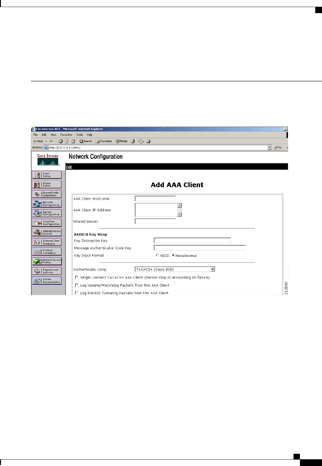
Configuring RADIUS on the ACS
Step 1 Choose Network Configuration on the ACS main page.
Step 2 Choose Add Entry under AAA Clients to add your controller to the server. The Add AAA Client page appears.
Figure 38: Add AAA Client Page on CiscoSecure ACS
Step 3 In the AAA Client Hostname text box, enter the name of your controller.
Step 4 In the AAA Client IP Address text box, enter the IP address of your controller.
Step 5 In the Shared Secret text box, enter the shared secret key to be used for authentication between the server and the
controller.
The shared secret key must be the same on both the server and the
controller.
Note
Cisco Wireless LAN Controller Configuration Guide, Release 7.4
OL-28744-01 353
Configuring RADIUS on the ACS

Step 6 From the Authenticate Using drop-down list, choose RADIUS (Cisco Airespace).
Step 7 Click Submit + Apply to save your changes.
Step 8 Choose Interface Configuration on the ACS main page.
Step 9 Choose RADIUS (Cisco Aironet). The RADIUS (Cisco Aironet) page appears.
Step 10 Under User Group, select the Cisco-Aironet-Session-Timeout check box.
Step 11 Click Submit to save your changes.
Step 12 On the ACS main page, from the left navigation pane, choose System Configuration.
Step 13 Choose Logging.
Step 14 When the Logging Configuration page appears, enable all of the events that you want to be logged and save your changes.
Step 15 On the ACS main page, from the left navigation pane, choose Group Setup.
Step 16 Choose a previously created group from the Group drop-down list.
This step assumes that you have already assigned users to groups on the ACS according to the roles to which
they will be assigned.
Note
Step 17 Click Edit Settings. The Group Setup page appears.
Step 18 Under Cisco Aironet Attributes, select the Cisco-Aironet-Session-Timeout check box and enter a session timeout
value in the edit box.
Step 19 Specify read-only or read-write access to controllers through RADIUS authentication, by setting the Service-Type
attribute (006) to Callback NAS Prompt for read-only access or to Administrative for read-write privileges. If you do
not set this attribute, the authentication process completes successfully (without an authorization error on the controller),
but you might be prompted to authenticate again.
If you set the Service-Type attribute on the ACS, make sure to select the Management check box on the RADIUS
Authentication Servers page of the controller GUI.
Note
Step 20 Click Submit to save your changes.
Configuring RADIUS (GUI)
Step 1 Choose Security >AAA >RADIUS.
Step 2 Perform one of the following:
•If you want to configure a RADIUS server for authentication, choose Authentication.
•If you want to configure a RADIUS server for accounting, choose Accounting.
The pages used to configure authentication and accounting contain mostly the same text boxes. Therefore, these
instructions walk through the configuration only once, using the Authentication pages as examples. You would
follow the same steps to configure multiple services and/or multiple servers.
Note
The RADIUS Authentication (or Accounting) Servers page appears.
This page lists any RADIUS servers that have already been configured.
•If you want to delete an existing server, hover your cursor over the blue drop-down arrow for that server and choose
Remove.
Cisco Wireless LAN Controller Configuration Guide, Release 7.4
354 OL-28744-01
Configuring RADIUS (GUI)

•If you want to make sure that the controller can reach a particular server, hover your cursor over the blue drop-down
arrow for that server and choose Ping.
Step 3 From the Call Station ID Type drop-down list, choose the option that is sent to the RADIUS server in the Access-Request
message. The following options are available:
•IP Address
•System MAC Address
•AP MAC Address
•AP MAC Address:SSID
•AP Name:SSID
•AP Name
•AP Group
•Flex Group
•AP Location
•VLAN ID
The AP Name:SSID, AP Name, AP Group, Flex Group, AP Location, and VLAN ID options are added in the
7.4 release.
Note
Step 4 Enable RADIUS-to-controller key transport using AES key wrap protection by selecting the Use AES Key Wrap check
box. The default value is unselected. This feature is required for FIPS customers.
Step 5 Click Apply. Perform one of the following:
•To edit an existing RADIUS server, click the server index number for that server. The RADIUS Authentication
(or Accounting) Servers > Edit page appears.
•To add a RADIUS server, click New. The RADIUS Authentication (or Accounting) Servers > New page appears.
Step 6 If you are adding a new server, choose a number from the Server Index (Priority) drop-down list to specify the priority
order of this server in relation to any other configured RADIUS servers providing the same service.
Step 7 If you are adding a new server, enter the IP address of the RADIUS server in the Server IP Address text box.
Step 8 From the Shared Secret Format drop-down list, choose ASCII or Hex to specify the format of the shared secret key
to be used between the controller and the RADIUS server. The default value is ASCII.
Step 9 In the Shared Secret and Confirm Shared Secret text boxes, enter the shared secret key to be used for authentication
between the controller and the server.
The shared secret key must be the same on both the server and the controller.Note
Step 10 If you are configuring a new RADIUS authentication server and want to enable AES key wrap, which makes the shared
secret between the controller and the RADIUS server more secure, follow these steps:
AES key wrap is designed for Federal Information Processing Standards (FIPS) customers and requires a
key-wrap compliant RADIUS authentication server.
Note
a) Select the Key Wrap check box.
b) From the Key Wrap Format drop-down list, choose ASCII or HEX to specify the format of the AES key wrap
keys: Key Encryption Key (KEK) and Message Authentication Code Key (MACK).
Cisco Wireless LAN Controller Configuration Guide, Release 7.4
OL-28744-01 355
Configuring RADIUS (GUI)

c) In the Key Encryption Key (KEK) text box, enter the 16-byte KEK.
d) In the Message Authentication Code Key (MACK) text box, enter the 20-byte KEK.
Step 11 If you are adding a new server, enter the RADIUS server’s UDP port number for the interface protocols in the Port
Number text box. The valid range is 1 to 65535, and the default value is 1812 for authentication and 1813 for accounting.
Step 12 From the Server Status text box, choose Enabled to enable this RADIUS server or choose Disabled to disable it. The
default value is enabled.
Step 13 If you are configuring a new RADIUS authentication server, choose Enabled from the Support for RFC 3576 drop-down
list to enable RFC 3576, which is an extension to the RADIUS protocol that allows dynamic changes to a user session,
or choose Disabled to disable this feature. The default value is Enabled. RFC 3576 includes support for disconnecting
users and changing authorizations applicable to a user session and supports disconnect and change-of-authorization
(CoA) messages. Disconnect messages cause a user session to be terminated immediately where CoA messages modify
session authorization attributes such as data filters.
Step 14 In the Server Timeout text box, enter the number of seconds between retransmissions. The valid range is 2 to 30 seconds,
and the default value is 2 seconds.
Select the Key Wrap check box.
We recommend that you increase the timeout value if you experience repeated reauthentication attempts or the
controller falls back to the backup server when the primary server is active and reachable.
Note
Step 15 Select the Network User check box to enable network user authentication (or accounting), or unselect it to disable this
feature. The default value is selected. If you enable this feature, this entry is considered the RADIUS authentication (or
accounting) server for network users. If you did not configure a RADIUS server entry on the WLAN, you must enable
this option for network users.
Step 16 If you are configuring a RADIUS authentication server, select the Management check box to enable management
authentication, or unselect it to disable this feature. The default value is selected. If you enable this feature, this entry is
considered the RADIUS authentication server for management users, and authentication requests go to the RADIUS
server.
Step 17 Select the IPSec check box to enable the IP security mechanism, or unselect it to disable this feature. The default value
is unselected.
Step 18 If you enabled IPsec in Step 17, follow these steps to configure additional IPsec parameters:
a) From the IPSec drop-down list, choose one of the following options as the authentication protocol to be used for IP
security: HMAC MD5 or HMAC SHA1. The default value is HMAC SHA1.
A message authentication code (MAC) is used between two parties that share a secret key to validate information
transmitted between them. HMAC (Hash MAC) is based on cryptographic hash functions. It can be used in combination
with any iterated cryptographic hash function. HMAC MD5 and HMAC SHA1 are two constructs of the HMAC
using the MD5 hash function and the SHA1 hash function. HMAC also uses a secret key for calculation and verification
of the message authentication values.
b) From the IPSec Encryption drop-down list, choose one of the following options to specify the IP security encryption
mechanism:
•DES—Data Encryption Standard that is a method of data encryption using a private (secret) key. DES applies
a 56-bit key to each 64-bit block of data.
•3DES—Data Encryption Standard that applies three keys in succession. This is the default value.
•AES CBC—Advanced Encryption Standard that uses keys with a length of 128, 192, or 256 bits to encrypt
data blocks with a length of 128, 192, or 256 bits. AES 128 CBC uses a 128-bit data path in Cipher Block
Chaining (CBC) mode.
Cisco Wireless LAN Controller Configuration Guide, Release 7.4
356 OL-28744-01
Configuring RADIUS (GUI)

c) From the IKE Phase 1 drop-down list, choose one of the following options to specify the Internet Key Exchange
(IKE) protocol: Aggressive or Main. The default value is Aggressive.
IKE Phase 1 is used to negotiate how IKE should be protected. Aggressive mode passes more information in fewer
packets with the benefit of slightly faster connection establishment at the cost of transmitting the identities of the
security gateways in the clear.
d) In the Lifetime text box, enter a value (in seconds) to specify the timeout interval for the session. The valid range is
1800 to 57600 seconds, and the default value is 1800 seconds.
e) From the IKE Diffie Hellman Group drop-down list, choose one of the following options to specify the IKE Diffie
Hellman group: Group 1 (768 bits),Group 2 (1024 bits), or Group 5 (1536 bits). The default value is Group 1
(768 bits).
Diffie-Hellman techniques are used by two devices to generate a symmetric key through which they can publicly
exchange values and generate the same symmetric key. Although all three groups provide security from conventional
attacks, Group 5 is considered more secure because of its larger key size. However, computations involving Group
1 and Group 2 based keys might occur slightly faster because of their smaller prime number size.
Step 19 Click Apply.
Step 20 Click Save Configuration.
Step 21 Repeat the previous steps if you want to configure any additional services on the same server or any additional RADIUS
servers.
Step 22 Specify the RADIUS server fallback behavior, as follows:
a) Choose Security >AAA >RADIUS > Fallback to open the RADIUS > Fallback Parameters to open the fallback
parameters page.
b) From the Fallback Mode drop-down list, choose one of the following options:
•Off—Disables RADIUS server fallback. This is the default value.
•Passive—Causes the controller to revert to a server with a lower priority from the available backup servers
without using extraneous probe messages. The controller ignores all inactive servers for a time period and retries
later when a RADIUS message needs to be sent.
•Active—Causes the controller to revert to a server with a lower priority from the available backup servers by
using RADIUS probe messages to proactively determine whether a server that has been marked inactive is back
online. The controller ignores all inactive servers for all active RADIUS requests. Once the primary server
receives a response from the recovered ACS server, the active fallback RADIUS server no longer sends probe
messages to the server requesting the active probe authentication.
c) If you enabled Active fallback mode in Step b, enter the name to be sent in the inactive server probes in the Username
text box. You can enter up to 16 alphanumeric characters. The default value is “cisco-probe.”
d) If you enabled Active fallback mode in Step b, enter the probe interval value (in seconds) in the Interval in Sec text
box. The interval serves as inactive time in passive mode and probe interval in active mode. The valid range is 180
to 3600 seconds, and the default value is 300 seconds.
Step 23 Specify the order of authentication when multiple databases are configured by choosing Security >Priority Order >
Management User. The Priority Order > Management User page appears.
Step 24 In the Order Used for Authentication text box, specify which servers have priority when the controller attempts to
authenticate management users. Use the >and <buttons to move servers between the Not Used and Order Used for
Authentication text boxes. After the desired servers appear in the Order Used for Authentication text box, use the Up
and Down buttons to move the priority server to the top of the list.
Cisco Wireless LAN Controller Configuration Guide, Release 7.4
OL-28744-01 357
Configuring RADIUS (GUI)

By default, the local database is always queried first. If the username is not found, the controller switches to the RADIUS
server if configured for RADIUS or to the TACACS+ server if configured for TACACS+. The default setting is local
and then RADIUS.
Step 25 Click Apply.
Step 26 Click Save Configuration.
Configuring RADIUS (CLI)
•Specify whether the IP address, system MAC address, AP MAC address, AP Ethernet MAC address of
the originator will be sent to the RADIUS server in the Access-Request message by entering this
command:
config radius callStationIdType {ipaddr |macaddr |ap-macaddr-only |ap-macaddr-ssid |||
ap-group-name |ap-location |ap-name |ap-name-ssid |flex-group-name |vlan-id}
The default is System MAC Address.Note
Do not use callStation IdType for IPv6-only clients.Caution
•Specify the delimiter to be used in the MAC addresses that are sent to the RADIUS authentication or
accounting server in Access-Request messages by entering this command:
config radius {auth |acct}mac-delimiter {colon | hyphen | single-hyphen | none}
where
•colon sets the delimiter to a colon (the format is xx:xx:xx:xx:xx:xx).
•hyphen sets the delimiter to a hyphen (the format is xx-xx-xx-xx-xx-xx). This is the default value.
•single-hyphen sets the delimiter to a single hyphen (the format is xxxxxx-xxxxxx).
•none disables delimiters (the format is xxxxxxxxxxxx).
•Configure a RADIUS authentication server by entering these commands:
•config radius auth add index server_ip_address port# {ascii |hex}shared_secret—Adds a
RADIUS authentication server.
•config radius auth keywrap {enable |disable}—Enables AES key wrap, which makes the shared
secret between the controller and the RADIUS server more secure. AES key wrap is designed for
Federal Information Processing Standards (FIPS) customers and requires a key-wrap compliant
RADIUS authentication server.
•config radius auth keywrap add {ascii |hex}kek mack index—Configures the AES key wrap
attributes
where
Cisco Wireless LAN Controller Configuration Guide, Release 7.4
358 OL-28744-01
Configuring RADIUS (CLI)

◦kek specifies the 16-byte Key Encryption Key (KEK).
◦mack specifies the 20-byte Message Authentication Code Key (MACK).
◦index specifies the index of the RADIUS authentication server on which to configure the
AES key wrap.
•config radius auth rfc3576 {enable |disable}index—Enables or disables RFC 3576, which is
an extension to the RADIUS protocol that allows dynamic changes to a user session. RFC 3576
includes support for disconnecting users and changing authorizations applicable to a user session
and supports disconnect and change-of-authorization (CoA) messages. Disconnect messages cause
a user session to be terminated immediately where CoA messages modify session authorization
attributes such as data filters.
•config radius auth retransmit-timeout index timeout—Configures the retransmission timeout
value for a RADIUS authentication server.
•config radius auth network index {enable |disable}—Enables or disables network user
authentication. If you enable this feature, this entry is considered the RADIUS authentication server
for network users. If you did not configure a RADIUS server entry on the WLAN, you must enable
this option for network users.
•config radius auth management index {enable |disable}—Enables or disables management
authentication. If you enable this feature, this entry is considered the RADIUS authentication server
for management users, and authentication requests go to the RADIUS server.
•config radius auth ipsec {enable |disable}index—Enables or disables the IP security mechanism.
•config radius auth ipsec authentication {hmac-md5 |hmac-sha1}index—Configures the
authentication protocol to be used for IP security.
•config radius auth ipsec encryption {3des |aes | des | none}index—Configures the IP security
encryption mechanism.
•config radius auth ipsec ike dh-group {group-1 |group-2 |group-5}index—Configures the
IKE Diffie-Hellman group.
•config radius auth ipsec ike lifetime interval index—Configures the timeout interval for the
session.
•config radius auth ipsec ike phase1{aggressive |main}index—Configures the Internet Key
Exchange (IKE) protocol.
•config radius auth {enable |disable}index—Enables or disables a RADIUS authentication server.
•config radius auth delete index—Deletes a previously added RADIUS authentication server.
•Configure a RADIUS accounting server by entering these commands:
•config radius acct add index server_ip_address port# {ascii |hex}shared_secret—Adds a
RADIUS accounting server.
•config radius acct server-timeout index timeout—Configures the retransmission timeout value
for a RADIUS accounting server.
•config radius acct network index {enable |disable}—Enables or disables network user accounting.
If you enable this feature, this entry is considered the RADIUS accounting server for network
Cisco Wireless LAN Controller Configuration Guide, Release 7.4
OL-28744-01 359
Configuring RADIUS (CLI)

users. If you did not configure a RADIUS server entry on the WLAN, you must enable this option
for network users.
•config radius acct ipsec {enable |disable}index—Enables or disables the IP security mechanism.
•config radius acct ipsec authentication {hmac-md5 |hmac-sha1}index—Configures the
authentication protocol to be used for IP security.
•config radius acct ipsec encryption {3des | aes | des | none}index—Configures the IP security
encryption mechanism.
•config radius acct ipsec ike dh-group {group-1 | group-2 | group-5} index—Configures the IKE
Diffie Hellman group.
•config radius acct ipsec ike lifetime interval index—Configures the timeout interval for the
session.
•config radius acct ipsec ike phase1{aggressive |main}index—Configures the Internet Key
Exchange (IKE) protocol.
•config radius acct {enable |disable} index—Enables or disables a RADIUS accounting server.
•config radius acct delete index—Deletes a previously added RADIUS accounting server.
•Configure the RADIUS server fallback behavior by entering this command:
config radius fallback-test mode {off | passive | active}
where
•off disables RADIUS server fallback.
•passive causes the controller to revert to a server with a lower priority from the available backup
servers without using extraneous probe messages. The controller simply ignores all inactive servers
for a time period and retries later when a RADIUS message needs to be sent.
•active causes the controller to revert to a server with a lower priority from the available backup
servers by using RADIUS probe messages to proactively determine whether a server that has been
marked inactive is back online. The controller simply ignores all inactive servers for all active
RADIUS requests. Once the primary server receives a response from the recovered ACS server,
the active fallback RADIUS server no longer sends probe messages to the server requesting the
active probe authentication.
•If you enabled Active mode in Step 5, enter these commands to configure additional fallback parameters:
•config radius fallback-test username username—Specifies the name to be sent in the inactive
server probes. You can enter up to 16 alphanumeric characters for the username parameter.
•config radius fallback-test interval interval—Specifies the probe interval value (in seconds).
•Save your changes by entering this command:
save config
•Configure the order of authentication when multiple databases are configured by entering this command:
config aaa auth mgmt AAA_server_type AAA_server_type
where AAA_server_type is local, radius, or tacacs.
To see the current management authentication server order, enter the show aaa auth command.
Cisco Wireless LAN Controller Configuration Guide, Release 7.4
360 OL-28744-01
Configuring RADIUS (CLI)

•See RADIUS statistics by entering these commands:
•show radius summary—Shows a summary of RADIUS servers and statistics with AP Ethernet
MAC configurations.
•show radius auth statistics—Shows the RADIUS authentication server statistics.
•show radius acct statistics—Shows the RADIUS accounting server statistics.
•show radius rfc3576 statistics—Shows a summary of the RADIUS RFC-3576 server.
•See active security associations by entering these commands:
•show ike {brief | detailed} ip_or_mac_addr—Shows a brief or detailed summary of active IKE
security associations.
•show ipsec {brief | detailed} ip_or_mac_addr—Shows a brief or detailed summary of active
IPSec security associations.
•Clear the statistics for one or more RADIUS servers by entering this command:
clear stats radius {auth |acct} {index |all}
•Make sure that the controller can reach the RADIUS server by entering this command:
ping server_ip_address
RADIUS Authentication Attributes Sent by the Controller
The following tables identify the RADIUS authentication attributes sent between the controller and the
RADIUS server in access-request and access-accept packets.
Table 8: Authentication Attributes Sent in Access-Request Packets
DescriptionAttribute ID
User-Name1
Password2
CHAP-Password3
NAS-IP-Address4
NAS-Port5
Service-Type4
6
Framed-MTU12
Called-Station-ID (MAC address)30
Calling-Station-ID (MAC address)31
NAS-Identifier32
Proxy-State33
CHAP-Challenge60
Cisco Wireless LAN Controller Configuration Guide, Release 7.4
OL-28744-01 361
RADIUS Authentication Attributes Sent by the Controller

DescriptionAttribute ID
NAS-Port-Type61
EAP-Message79
TPLUS-Role243
4To specify read-only or read-write access to controllers through RADIUS authentication, you must set the Service-Type attribute (6) on the RADIUS server
to Callback NAS Prompt for read-only access or to Administrative for read-write privileges.
Table 9: Authentication Attributes Honored in Access-Accept Packets (Cisco)
DescriptionAttribute ID
Cisco-LEAP-Session-Key1
Cisco-Keywrap-Msg-Auth-Code2
Cisco-Keywrap-NonCE3
Cisco-Keywrap-Key4
Cisco-URL-Redirect5
Cisco-URL-Redirect-ACL6
These Cisco-specific attributes are not supported: Auth-Algo-Type and SSID.Note
Table 10: Authentication Attributes Honored in Access-Accept Packets (Standard)
DescriptionAttribute ID
Service-Type. To specify read-only or read-write access to controllers
through RADIUS authentication, you must set the Service-Type attribute
(6) on the RADIUS server to Callback NAS Prompt for read-only access
or to Administrative for read-write privileges.
6
Framed-IP-Address8
Class25
Vendor-Specific26
Timeout27
Termination-Action29
Acct-Status-Type40
Tunnel-Type64
EAP-Message79
Cisco Wireless LAN Controller Configuration Guide, Release 7.4
362 OL-28744-01
RADIUS Authentication Attributes Sent by the Controller

Tunnel-Group-ID81
Message authentication is not supported.Note
Table 11: Authentication Attributes Honored in Access-Accept Packets (Microsoft)
DescriptionAttribute ID
MS-CHAP-Challenge11
MS-MPPE-Send-Key16
MS-MPPE-Receive-Key17
MS-MSCHAP2-Response25
MS-MSCHAP2-Success26
Table 12: Authentication Attributes Honored in Access-Accept Packets (Airespace)
DescriptionAttribute ID
VAP-ID1
DSCP3
8021P-Type4
VLAN-Interface-Name5
ACL-Name6
Data-Bandwidth-Average-Contract7
Real-Time-Bandwidth-Average-Contract8
Data-Bandwidth-Burst-Contract9
Real-Time-Bandwidth-Burst-Contract10
Guest-Role-Name11
Data-Bandwidth-Average-Contract-US13
Real-Time-Bandwidth-Average-Contract-US14
Data-Bandwidth-Burst-Contract-US15
Real-Time-Bandwidth-Burst-Contract-US16
Cisco Wireless LAN Controller Configuration Guide, Release 7.4
OL-28744-01 363
RADIUS Authentication Attributes Sent by the Controller

Authentication Attributes Honored in Access-Accept Packets (Airespace)
This section lists the RADIUS authentication Airespace attributes currently supported on the Cisco WLC.
VAP ID
This attribute indicates the WLAN ID of the WLAN to which the client should belong. When the WLAN-ID
attribute is present in the RADIUS Access Accept, the system applies the WLAN-ID (SSID) to the client
station after it authenticates. The WLAN ID is sent by the Cisco WLC in all instances of authentication except
IPsec. In case of web authentication, if the Cisco WLC receives a WLAN-ID attribute in the authentication
response from the AAA server, and it does not match the ID of the WLAN, authentication is rejected. Other
types of security methods do not do this. The fields are transmitted from left to right.
0123
01234567890123456789012345678901
+-+-+-+-+-+-+-+-+-+-+-+-+-+-+-+-+-+-+-+-+-+-+-+-+-+-+-+-+-+-+-+-+
| Type | Length | Vendor-Id
+-+-+-+-+-+-+-+-+-+-+-+-+-+-+-+-+-+-+-+-+-+-+-+-+-+-+-+-+-+-+-+-+
Vendor-Id (cont.) | Vendor type | Vendor length |
+-+-+-+-+-+-+-+-+-+-+-+-+-+-+-+-+-+-+-+-+-+-+-+-+-+-+-+-+-+-+-+-+
| WLAN ID (VALUE) |
+-+-+-+-+-+-+-+-+-+-+-+-+-+-+-+-+-+-+-+-+-+-+-+-+-+-+-+-+-+-+-+-+
•Type –26 for Vendor-Specific
•Length –10
•Vendor-Id –14179
•Vendor type –1
•Vendor length –4
•Value –ID of the WLAN to which the client should belong.
QoS-Level
This attribute indicates the QoS level to be applied to the mobile client's traffic within the switching fabric,
as well as over the air. This example shows a summary of the QoS-Level Attribute format. The fields are
transmitted from left to right.
0123
01234567890123456789012345678901
+-+-+-+-+-+-+-+-+-+-+-+-+-+-+-+-+-+-+-+-+-+-+-+-+-+-+-+-+-+-+-+-+
| Type | Length | Vendor-Id
+-+-+-+-+-+-+-+-+-+-+-+-+-+-+-+-+-+-+-+-+-+-+-+-+-+-+-+-+-+-+-+-+
Vendor-Id (cont.) | Vendor type | Vendor length |
+-+-+-+-+-+-+-+-+-+-+-+-+-+-+-+-+-+-+-+-+-+-+-+-+-+-+-+-+-+-+-+-+
| QoS Level |
+-+-+-+-+-+-+-+-+-+-+-+-+-+-+-+-+-+-+-+-+-+-+-+-+-+-+-+-+-+-+-+-+
•Type –26 for Vendor-Specific
•Length –10
•Vendor-Id –14179
•Vendor type –2
•Vendor length –4
Cisco Wireless LAN Controller Configuration Guide, Release 7.4
364 OL-28744-01
Authentication Attributes Honored in Access-Accept Packets (Airespace)

•Value –Three octets:
◦3–Bronze (Background)
◦0–Silver (Best Effort)
◦1–Gold (Video)
◦2–Platinum (Voice)
Differentiated Services Code Point (DSCP)
DSCP is a packet header code that can be used to provide differentiated services based on the QoS levels.
This attribute defines the DSCP value to be applied to a client. When present in a RADIUS Access Accept,
the DSCP value overrides the DSCP value specified in the WLAN profile. The fields are transmitted from
left to right.
0123
01234567890123456789012345678901
+-+-+-+-+-+-+-+-+-+-+-+-+-+-+-+-+-+-+-+-+-+-+-+-+-+-+-+-+-+-+-+-+
| Type | Length | Vendor-Id
+-+-+-+-+-+-+-+-+-+-+-+-+-+-+-+-+-+-+-+-+-+-+-+-+-+-+-+-+-+-+-+-+
Vendor-Id (cont.) | Vendor type | Vendor length |
+-+-+-+-+-+-+-+-+-+-+-+-+-+-+-+-+-+-+-+-+-+-+-+-+-+-+-+-+-+-+-+-+
| DSCP (VALUE) |
+-+-+-+-+-+-+-+-+-+-+-+-+-+-+-+-+-+-+-+-+-+-+-+-+-+-+-+-+-+-+-+-+
•Type –26 for Vendor-Specific
•Length –10
•Vendor-Id –14179
•Vendor type –3
•Vendor length –4
•Value –DSCP value to be applied for the client.
802.1p Tag Type
802.1p VLAN tag received from the client, defining the access priority. This tag maps to the QoS Level for
client-to-network packets. This attribute defines the 802.1p priority to be applied to the client. When present
in a RADIUS Access Accept, the 802.1p value overrides the default specified in the WLAN profile. The fields
are transmitted from left to right.
0123
01234567890123456789012345678901
+-+-+-+-+-+-+-+-+-+-+-+-+-+-+-+-+-+-+-+-+-+-+-+-+-+-+-+-+-+-+-+-+
| Type | Length | Vendor-Id
+-+-+-+-+-+-+-+-+-+-+-+-+-+-+-+-+-+-+-+-+-+-+-+-+-+-+-+-+-+-+-+-+
Vendor-Id (cont.) | Vendor type | Vendor length |
+-+-+-+-+-+-+-+-+-+-+-+-+-+-+-+-+-+-+-+-+-+-+-+-+-+-+-+-+-+-+-+
| 802.1p (VALUE) |
+-+-+-+-+-+-+-+-+-+-+-+-+-+-+-+-+-+-+-+-+-+-+-+-+-+-+-+-+-+-+-
•Type –26 for Vendor-Specific
Cisco Wireless LAN Controller Configuration Guide, Release 7.4
OL-28744-01 365
Authentication Attributes Honored in Access-Accept Packets (Airespace)

•Length –10
•Vendor-Id –14179
•Vendor type –4
•Vendor length –3
•Value –802.1p priority to be applied to a client.
VLAN Interface Name
This attribute indicates the VLAN interface a client is to be associated to. A summary of the Interface-Name
Attribute format is shown below. The fields are transmitted from left to right.
0123
01234567890123456789012345678901
+-+-+-+-+-+-+-+-+-+-+-+-+-+-+-+-+-+-+-+-+-+-+-+-+-+-+-+-+-+-+-+-+
| Type | Length | Vendor-Id
+-+-+-+-+-+-+-+-+-+-+-+-+-+-+-+-+-+-+-+-+-+-+-+-+-+-+-+-+-+-+-+-+
Vendor-Id (cont.) | Vendor type | Vendor length |
+-+-+-+-+-+-+-+-+-+-+-+-+-+-+-+-+-+-+-+-+-+-+-+-+-+-+-+-+-+-+-+-+
| Interface Name...
+-+-+-+-+-+-+-+-+-+-+-+-+-+-+-
•Type –26 for Vendor-Specific
•Length –>7
•Vendor-Id –14179
•Vendor type –5
•Vendor length –>0
•Value –A string that includes the name of the interface the client is to be assigned to.
This attribute only works when MAC filtering is enabled or if 802.1X or WPA is used
as the security policy.
Note
ACL-Name
This attribute indicates the ACL name to be applied to the client. A summary of the ACL-Name Attribute
format is shown below. The fields are transmitted from left to right.
0123
01234567890123456789012345678901
+-+-+-+-+-+-+-+-+-+-+-+-+-+-+-+-+-+-+-+-+-+-+-+-+-+-+-+-+-+-+-+-+
| Type | Length | Vendor-Id
+-+-+-+-+-+-+-+-+-+-+-+-+-+-+-+-+-+-+-+-+-+-+-+-+-+-+-+-+-+-+-+-+
Vendor-Id (cont.) | Vendor type | Vendor length |
+-+-+-+-+-+-+-+-+-+-+-+-+-+-+-+-+-+-+-+-+-+-+-+-+-+-+-+-+-+-+-+-+
| ACL Name...
+-+-+-+-+-+-+-+-+-+-+-+-+-+-+-
•Type –26 for Vendor-Specific
•Length –>7
Cisco Wireless LAN Controller Configuration Guide, Release 7.4
366 OL-28744-01
Authentication Attributes Honored in Access-Accept Packets (Airespace)

•Vendor-Id –14179
•Vendor type –6
•Vendor length –>0
•Value –A string that includes the name of the ACL to use for the client
Data Bandwidth Average Contract
This attribute is a rate limiting value. It indicates the Data Bandwidth Average Contract that will be applied
for a client for non-realtime traffic such as TCP. This value is specific for downstream direction from wired
to wireless. When present in a RADIUS Access Accept, the Data Bandwidth Average Contract value overrides
the Average Data Rate value present in the WLAN or QoS Profile. The fields are transmitted from left to
right.
0123
01234567890123456789012345678901
+-+-+-+-+-+-+-+-+-+-+-+-+-+-+-+-+-+-+-+-+-+-+-+-+-+-+-+-+-+-+-+-+
| Type | Length | Vendor-Id
+-+-+-+-+-+-+-+-+-+-+-+-+-+-+-+-+-+-+-+-+-+-+-+-+-+-+-+-+-+-+-+-+
Vendor-Id (cont.) | Vendor type | Vendor length |
+-+-+-+-+-+-+-+-+-+-+-+-+-+-+-+-+-+-+-+-+-+-+-+-+-+-+-+-+-+-+-+-+
| Data Bandwidth Average Contract...
+-+-+-+-+-+-+-+-+-+-+-+-+-+-+-
•Type –26 for Vendor-Specific
•Length –10
•Vendor-Id –14179
•Vendor type –7
•Vendor length –4
•Value –A value in kbps
Real Time Bandwidth Average Contract
This attribute is a rate limiting value. It indicates the Data Bandwidth Average Contract that will be applied
to a client for realtime traffic such as UDP. This value is specific for downstream direction from wired to
wireless. When present in a RADIUS Access Accept, the Real Time Bandwidth Average Contract value
overrides the Average Real-Time Rate value present in the WLAN or QoS Profile. The fields are transmitted
from left to right.
0123
01234567890123456789012345678901
+-+-+-+-+-+-+-+-+-+-+-+-+-+-+-+-+-+-+-+-+-+-+-+-+-+-+-+-+-+-+-+-+
| Type | Length | Vendor-Id
+-+-+-+-+-+-+-+-+-+-+-+-+-+-+-+-+-+-+-+-+-+-+-+-+-+-+-+-+-+-+-+-+
Vendor-Id (cont.) | Vendor type | Vendor length |
+-+-+-+-+-+-+-+-+-+-+-+-+-+-+-+-+-+-+-+-+-+-+-+-+-+-+-+-+-+-+-+-+
| Real Time Bandwidth Average Contract...
+-+-+-+-+-+-+-+-+-+-+-+-+-+-+-
•Type –26 for Vendor-Specific
•Length –10
•Vendor-Id –14179
Cisco Wireless LAN Controller Configuration Guide, Release 7.4
OL-28744-01 367
Authentication Attributes Honored in Access-Accept Packets (Airespace)

•Vendor type –8
•Vendor length –4
•Value –A value in kbps
Data Bandwidth Burst Contract
This attribute is a rate limiting value. It indicates the Data Bandwidth Burst Contract that will be applied to
a client for non-realtime traffic such as TCP. This value is specific to downstream direction from wired to
wireless. When present in a RADIUS Access Accept, the Data Bandwidth Burst Contract value overrides the
Burst Data Rate value present in the WLAN or QoS Profile. The fields are transmitted from left to right.
0123
01234567890123456789012345678901
+-+-+-+-+-+-+-+-+-+-+-+-+-+-+-+-+-+-+-+-+-+-+-+-+-+-+-+-+-+-+-+-+
| Type | Length | Vendor-Id
+-+-+-+-+-+-+-+-+-+-+-+-+-+-+-+-+-+-+-+-+-+-+-+-+-+-+-+-+-+-+-+-+
Vendor-Id (cont.) | Vendor type | Vendor length |
+-+-+-+-+-+-+-+-+-+-+-+-+-+-+-+-+-+-+-+-+-+-+-+-+-+-+-+-+-+-+-+-+
| Data Bandwidth Burst Contract...
+-+-+-+-+-+-+-+-+-+-+-+-+-+-+-
•Type –26 for Vendor-Specific
•Length –10
•Vendor-Id –14179
•Vendor type –9
•Vendor length –4
•Value –A value in kbps
Real Time Bandwidth Burst Contract
This attribute is a rate limiting value. It indicates the Data Bandwidth Burst Contract that will be applied to
a client for realtime traffic such as UDP. This value is specific to downstream direction from wired to wireless.
When present in a RADIUS Access Accept, the Real Time Bandwidth Burst Contract value overrides the
Burst Real-Time Rate value present in the WLAN or QoS Profile. The fields are transmitted from left to right.
0123
01234567890123456789012345678901
+-+-+-+-+-+-+-+-+-+-+-+-+-+-+-+-+-+-+-+-+-+-+-+-+-+-+-+-+-+-+-+-+
| Type | Length | Vendor-Id
+-+-+-+-+-+-+-+-+-+-+-+-+-+-+-+-+-+-+-+-+-+-+-+-+-+-+-+-+-+-+-+-+
Vendor-Id (cont.) | Vendor type | Vendor length |
+-+-+-+-+-+-+-+-+-+-+-+-+-+-+-+-+-+-+-+-+-+-+-+-+-+-+-+-+-+-+-+-+
| Real Time Bandwidth Burst Contract...
+-+-+-+-+-+-+-+-+-+-+-+-+-+-+-
•Type –26 for Vendor-Specific
•Length –10
•Vendor-Id –14179
•Vendor type –10
•Vendor length –4
Cisco Wireless LAN Controller Configuration Guide, Release 7.4
368 OL-28744-01
Authentication Attributes Honored in Access-Accept Packets (Airespace)

•Value –A value in kbps
Guest Role Name
This attribute provides the bandwidth contract values to be applied for an authenticating user. When present
in a RADIUS Access Accept, the bandwidth contract values defined for the Guest Role overrides the bandwidth
contract values (based on QOS value) specified for the WLAN. The fields are transmitted from left to right.
0123
01234567890123456789012345678901
+-+-+-+-+-+-+-+-+-+-+-+-+-+-+-+-+-+-+-+-+-+-+-+-+-+-+-+-+-+-+-+-+
| Type | Length | Vendor-Id
+-+-+-+-+-+-+-+-+-+-+-+-+-+-+-+-+-+-+-+-+-+-+-+-+-+-+-+-+-+-+-+-+
Vendor-Id (cont.) | Vendor type | Vendor length |
+-+-+-+-+-+-+-+-+-+-+-+-+-+-+-+-+-+-+-+-+-+-+-+-+-+-+-+-+-+-+-+-+
| GuestRoleName ...
+-+-+-+-+-+-+-+-+-+-+-+-+-+-+-
•Type –26 for Vendor-Specific
•Length –10
•Vendor-Id –14179
•Vendor type –11
•Vendor length –Variable based on the Guest Role Name length
•Value –A string of alphanumeric characters
Data Bandwidth Average Contract Upstream
This attribute is a rate limiting value. It indicates the Data Bandwidth Average Contract that will be applied
to a client for non-realtime traffic such as TCP. This value is specific to upstream direction from wireless to
wired. When present in a RADIUS Access Accept, the Data Bandwidth Average Contract value overrides the
Average Data Rate value present in the WLAN or QoS Profile. The fields are transmitted from left to right.
0123
01234567890123456789012345678901
+-+-+-+-+-+-+-+-+-+-+-+-+-+-+-+-+-+-+-+-+-+-+-+-+-+-+-+-+-+-+-+-+
| Type | Length | Vendor-Id
+-+-+-+-+-+-+-+-+-+-+-+-+-+-+-+-+-+-+-+-+-+-+-+-+-+-+-+-+-+-+-+-+
Vendor-Id (cont.) | Vendor type | Vendor length |
+-+-+-+-+-+-+-+-+-+-+-+-+-+-+-+-+-+-+-+-+-+-+-+-+-+-+-+-+-+-+-+-+
| Data Bandwidth Average Contract Upstream...
+-+-+-+-+-+-+-+-+-+-+-+-+-+-+-
•Type –26 for Vendor-Specific
•Length –10
•Vendor-Id –14179
•Vendor type –13
•Vendor length –4
•Value –A value in kbps
Cisco Wireless LAN Controller Configuration Guide, Release 7.4
OL-28744-01 369
Authentication Attributes Honored in Access-Accept Packets (Airespace)

Real Time Bandwidth Average Contract Upstream
This attribute is a rate limiting value. It indicates the Data Bandwidth Average Contract that will be applied
to a client for realtime traffic such as UDP. This value is specific to upstream direction from wireless to wired.
When present in a RADIUS Access Accept, the Real Time Bandwidth Average Contract value overrides the
Average Real-Time Rate value present in the WLAN or QoS Profile. The fields are transmitted from left to
right.
0123
01234567890123456789012345678901
+-+-+-+-+-+-+-+-+-+-+-+-+-+-+-+-+-+-+-+-+-+-+-+-+-+-+-+-+-+-+-+-+
| Type | Length | Vendor-Id
+-+-+-+-+-+-+-+-+-+-+-+-+-+-+-+-+-+-+-+-+-+-+-+-+-+-+-+-+-+-+-+-+
Vendor-Id (cont.) | Vendor type | Vendor length |
+-+-+-+-+-+-+-+-+-+-+-+-+-+-+-+-+-+-+-+-+-+-+-+-+-+-+-+-+-+-+-+-+
| Real Time Bandwidth Average Contract Upstream...
+-+-+-+-+-+-+-+-+-+-+-+-+-+-+-
•Type –26 for Vendor-Specific
•Length –10
•Vendor-Id –14179
•Vendor type –14
•Vendor length –4
•Value –A value in kbps
Data Bandwidth Burst Contract Upstream
This attribute is a rate limiting value. It indicates the Data Bandwidth Burst Contract that will be applied to
a client for non-realtime traffic such as TCP. This value is specific to upstream direction from wireless to
wired. When present in a RADIUS Access Accept, the Data Bandwidth Burst Contract value overrides the
Burst Data Rate value present in the WLAN or QoS Profile. The fields are transmitted from left to right.
0123
01234567890123456789012345678901
+-+-+-+-+-+-+-+-+-+-+-+-+-+-+-+-+-+-+-+-+-+-+-+-+-+-+-+-+-+-+-+-+
| Type | Length | Vendor-Id
+-+-+-+-+-+-+-+-+-+-+-+-+-+-+-+-+-+-+-+-+-+-+-+-+-+-+-+-+-+-+-+-+
Vendor-Id (cont.) | Vendor type | Vendor length |
+-+-+-+-+-+-+-+-+-+-+-+-+-+-+-+-+-+-+-+-+-+-+-+-+-+-+-+-+-+-+-+-+
| Data Bandwidth Burst Contract Upstream...
+-+-+-+-+-+-+-+-+-+-+-+-+-+-+-
•Type –26 for Vendor-Specific
•Length –10
•Vendor-Id –14179
•Vendor type –15
•Vendor length –4
•Value –A value in kbps
Cisco Wireless LAN Controller Configuration Guide, Release 7.4
370 OL-28744-01
Authentication Attributes Honored in Access-Accept Packets (Airespace)

Real Time Bandwidth Burst Contract Upstream
This attribute is a rate limiting value. It indicates the Data Bandwidth Burst Contract that will be applied to
a client for realtime traffic such as UDP. This value is specific to upstream direction from wireless to wired.
When present in a RADIUS Access Accept, the Real Time Bandwidth Burst Contract value overrides the
Burst Real-Time Rate value present in the WLAN or QoS Profile. The fields are transmitted from left to right.
0123
01234567890123456789012345678901
+-+-+-+-+-+-+-+-+-+-+-+-+-+-+-+-+-+-+-+-+-+-+-+-+-+-+-+-+-+-+-+-+
| Type | Length | Vendor-Id
+-+-+-+-+-+-+-+-+-+-+-+-+-+-+-+-+-+-+-+-+-+-+-+-+-+-+-+-+-+-+-+-+
Vendor-Id (cont.) | Vendor type | Vendor length |
+-+-+-+-+-+-+-+-+-+-+-+-+-+-+-+-+-+-+-+-+-+-+-+-+-+-+-+-+-+-+-+-+
| Real Time Bandwidth Burst Contract Upstream...
+-+-+-+-+-+-+-+-+-+-+-+-+-+-+-
•Type –26 for Vendor-Specific
•Length –10
•Vendor-Id –14179
•Vendor type –16
•Vendor length –4
•Value –A value in kbps
RADIUS Accounting Attributes
This table identifies the RADIUS accounting attributes for accounting requests sent from a controller to the
RADIUS server.
Table 13: Accounting Attributes for Accounting Requests
DescriptionAttribute ID
User-Name1
NAS-IP-Address4
NAS-Port5
Framed-IP-Address8
Class25
Called-Station-ID (MAC address)30
Calling-Station-ID (MAC address)31
NAS-Identifier32
Accounting-Status-Type40
Accounting-Delay-Time (Stop and interim messages only)41
Accounting-Input-Octets (Stop and interim messages only)42
Cisco Wireless LAN Controller Configuration Guide, Release 7.4
OL-28744-01 371
RADIUS Accounting Attributes

DescriptionAttribute ID
Accounting-Output-Octets (Stop and interim messages only)43
Accounting-Session-ID44
Accounting-Authentic45
Accounting-Session-Time (Stop and interim messages only)46
Accounting-Input-Packets (Stop and interim messages only)47
Accounting-Output-Packets (Stop and interim messages only)48
Accounting-Terminate-Cause (Stop messages only)49
Accounting-Input-Gigawords52
Accounting-Output-Gigawords53
Event-Timestamp55
Tunnel-Type64
Tunnel-Medium-Type65
Tunnel-Group-ID81
This table lists the different values for the Accounting-Status-Type attribute (40).
Table 14: Accounting-Status-Type Attribute Values
DescriptionAttribute ID
Start1
Stop2
Interim-Update3
Accounting-On7
Accounting-Off8
Reserved for Tunneling Accounting9-14
Reserved for Failed15
Cisco Wireless LAN Controller Configuration Guide, Release 7.4
372 OL-28744-01
RADIUS Accounting Attributes

CHAPTER 42
Configuring TACACS+
•Information About TACACS+, page 373
•Configuring TACACS+ on the ACS, page 376
•Configuring TACACS+ (GUI), page 378
•Configuring TACACS+ (CLI), page 379
•Viewing the TACACS+ Administration Server Logs, page 380
Information About TACACS+
Terminal Access Controller Access Control System Plus (TACACS+) is a client/server protocol that provides
centralized security for users attempting to gain management access to a controller. It serves as a backend
database similar to local and RADIUS. However, local and RADIUS provide only authentication support and
limited authorization support while TACACS+ provides three services:
•Authentication—The process of verifying users when they attempt to log into the controller.
Users must enter a valid username and password in order for the controller to authenticate users to the
TACACS+ server. The authentication and authorization services are tied to one another. For example,
if authentication is performed using the local or RADIUS database, then authorization would use the
permissions associated with the user in the local or RADIUS database (which are read-only, read-write,
and lobby-admin) and not use TACACS+. Similarly, when authentication is performed using TACACS+,
authorization is tied to TACACS+.
When multiple databases are configured, you can use the controller GUI or CLI to
specify the sequence in which the backend databases should be tried.
Note
•Authorization—The process of determining the actions that users are allowed to take on the controller
based on their level of access.
For TACACS+, authorization is based on privilege (or role) rather than specific actions. The available
roles correspond to the seven menu options on the controller GUI: MONITOR, WLAN, CONTROLLER,
WIRELESS, SECURITY, MANAGEMENT, and COMMANDS. An additional role, LOBBY, is available
for users who require only lobby ambassador privileges. The roles to which users are assigned are
Cisco Wireless LAN Controller Configuration Guide, Release 7.4
OL-28744-01 373

configured on the TACACS+ server. Users can be authorized for one or more roles. The minimum
authorization is MONITOR only, and the maximum is ALL, which authorizes the user to execute the
functionality associated with all seven menu options. For example, a user who is assigned the role of
SECURITY can make changes to any items appearing on the Security menu (or designated as security
commands in the case of the CLI). If users are not authorized for a particular role (such as WLAN), they
can still access that menu option in read-only mode (or the associated CLI show commands). If the
TACACS+ authorization server becomes unreachable or unable to authorize, users are unable to log
into the controller.
If users attempt to make changes on a controller GUI page that are not permitted for
their assigned role, a message appears indicating that they do not have sufficient privilege.
If users enter a controller CLI command that is not permitted for their assigned role, a
message may appear indicating that the command was successfully executed although
it was not. In this case, the following additional message appears to inform users that
they lack sufficient privileges to successfully execute the command: “Insufficient
Privilege! Cannot execute command!”
Note
•Accounting—The process of recording user actions and changes.
Whenever a user successfully executes an action, the TACACS+ accounting server logs the changed
attributes, the user ID of the person who made the change, the remote host where the user is logged in,
the date and time when the command was executed, the authorization level of the user, and a description
of the action performed and the values provided. If the TACACS+ accounting server becomes unreachable,
users are able to continue their sessions uninterrupted.
TACACS+ uses Transmission Control Protocol (TCP) for its transport, unlike RADIUS which uses User
Datagram Protocol (UDP). It maintains a database and listens on TCP port 49 for incoming requests. The
controller, which requires access control, acts as the client and requests AAA services from the server. The
traffic between the controller and the server is encrypted by an algorithm defined in the protocol and a shared
secret key configured on both devices.
You can configure up to three TACACS+ authentication, authorization, and accounting servers each. For
example, you may want to have one central TACACS+ authentication server but several TACACS+
authorization servers in different regions. If you configure multiple servers of the same type and the first one
fails or becomes unreachable, the controller automatically tries the second one and then the third one if
necessary.
If multiple TACACS+ servers are configured for redundancy, the user database must be identical in all
the servers for the backup to work properly.
Note
The following are some guidelines about TACACS+:
•You must configure TACACS+ on both your CiscoSecure Access Control Server (ACS) and your
controller. You can configure the controller through either the GUI or the CLI.
•TACACS+ is supported on CiscoSecure ACS version 3.2 and later releases. See the CiscoSecure ACS
documentation for the version that you are running.
•One Time Passwords (OTPs) are supported on the controller using TACACS. In this configuration, the
controller acts as a transparent passthrough device. The controller forwards all client requests to the
Cisco Wireless LAN Controller Configuration Guide, Release 7.4
374 OL-28744-01
Information About TACACS+

TACACS server without inspecting the client behavior. When using OTP, the client must establish a
single connection to the controller to function properly. The controller currently does not have any
intelligence or checks to correct a client that is trying to establish multiple connections.
•We recommend that you increase the retransmit timeout value for TACACS+ authentication, authorization,
and accounting servers if you experience repeated reauthentication attempts or the controller falls back
to the backup server when the primary server is active and reachable. The default retransmit timeout
value is 2 seconds and you can increase the retransmit timeout value to a maximum of 30 seconds.
TACACS+ VSA
The Internet Engineering Task Force (IETF) draft standard specifies a method for communicating
vendor-specific attributes (VSAs) between the network access server and the TACACS+ server. The IETF
uses attribute 26. VSAs allow vendors to support their own extended attributes that are not suitable for general
use.
The Cisco TACACS+ implementation supports one vendor-specific option using the format recommended
in the IETF specification. The Cisco vendor ID is 9, and the supported option is vendor type 1, which is named
cisco-av-pair. The value is a string with the following format:
protocol : attribute separator value *
The protocol is a Cisco attribute for a particular type of authorization, the separator is = (equal sign) for
mandatory attributes, and * (asterisk) indicates optional attributes.
Cisco Wireless LAN Controller Configuration Guide, Release 7.4
OL-28744-01 375
Information About TACACS+
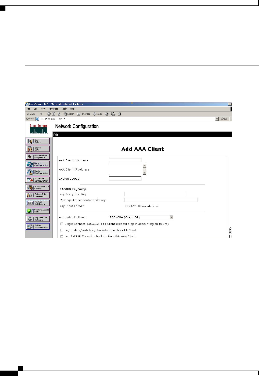
Configuring TACACS+ on the ACS
Step 1 Choose Network Configuration on the ACS main page.
Step 2 Choose Add Entry under AAA Clients to add your controller to the server. The Add AAA Client page appears.
Figure 39: Add AAA Client Page on CiscoSecure ACS
Step 3 In the AAA Client Hostname text box, enter the name of your controller.
Step 4 In the AAA Client IP Address text box, enter the IP address of your controller.
Step 5 In the Shared Secret text box, enter the shared secret key to be used for authentication between the server and the controller.
The shared secret key must be the same on both the server and the
controller.
Note
Cisco Wireless LAN Controller Configuration Guide, Release 7.4
376 OL-28744-01
Configuring TACACS+ on the ACS

Step 6 From the Authenticate Using drop-down list, choose TACACS+ (Cisco IOS).
Step 7 Click Submit + Apply to save your changes.
Step 8 On the ACS main page, in the left navigation pane, choose Interface Configuration.
Step 9 Choose TACACS+ (Cisco IOS). The TACACS+ (Cisco) page appears.
Step 10 Under TACACS+ Services, select the Shell (exec) check box.
Step 11 Under New Services, select the first check box and enter ciscowlc in the Service text box and common in the Protocol
text box.
Step 12 Under Advanced Configuration Options, select the Advanced TACACS+ Features check box.
Step 13 Click Submit to save your changes.
Step 14 On the ACS main page, in the left navigation pane, choose System Configuration.
Step 15 Choose Logging.
Step 16 When the Logging Configuration page appears, enable all of the events that you want to be logged and save your changes.
Step 17 On the ACS main page, in the left navigation pane, choose Group Setup.
Step 18 From the Group drop-down list, choose a previously created group.
This step assumes that you have already assigned users to groups on the ACS according to the roles to which
they will be assigned.
Note
Step 19 Click Edit Settings. The Group Setup page appears.
Step 20 Under TACACS+ Settings, select the ciscowlc common check box.
Step 21 Select the Custom Attributes check box.
Step 22 In the text box below Custom Attributes, specify the roles that you want to assign to this group. The available roles are
MONITOR, WLAN, CONTROLLER, WIRELESS, SECURITY, MANAGEMENT, COMMANDS, ALL, and LOBBY.
The first seven correspond to the menu options on the controller GUI and allow access to those particular controller
features. If a user is not entitled for a particular task, the user is still allowed to access that task in read-only mode. You
can enter one or multiple roles, depending on the group's needs. Use ALL to specify all seven roles or LOBBY to specify
the lobby ambassador role. Enter the roles using this format:
rolex=ROLE
For example, to specify the WLAN, CONTROLLER, and SECURITY roles for a particular user group, you would enter
the following text:
role1=WLAN
role2=CONTROLLER
role3=SECURITY?
To give a user group access to all seven roles, you would enter the following text:
role1=ALL?
Make sure to enter the roles using the format shown above. The roles must be in all uppercase letters, and there
can be no spaces within the text.
Note
You should not combine the MONITOR role or the LOBBY role with any other roles. If you specify one of
these two roles in the Custom Attributes text box, users will have MONITOR or LOBBY privileges only, even
if additional roles are specified.
Note
Step 23 Click Submit to save your changes.
Cisco Wireless LAN Controller Configuration Guide, Release 7.4
OL-28744-01 377
Configuring TACACS+ on the ACS

Configuring TACACS+ (GUI)
Step 1 Choose Security >AAA >TACACS+.
Step 2 Perform one of the following:
•If you want to configure a TACACS+ server for authentication, choose Authentication.
•If you want to configure a TACACS+ server for authorization, choose Authorization.
•If you want to configure a TACACS+ server for accounting, choose Accounting.
The pages used to configure authentication, authorization, and accounting all contain the same text boxes.
Therefore, these instructions walk through the configuration only once, using the Authentication pages as
examples. You would follow the same steps to configure multiple services and/or multiple servers.
Note
For basic management authentication via TACACS+ to succeed, it is required to configure authentication and
authorization servers on the WLC. Accounting configuration is optional.
Note
The TACACS+ (Authentication, Authorization, or Accounting) Servers page appears. This page lists any TACACS+
servers that have already been configured.
•If you want to delete an existing server, hover your cursor over the blue drop-down arrow for that server and choose
Remove.
•If you want to make sure that the controller can reach a particular server, hover your cursor over the blue drop-down
arrow for that server and choose Ping.
Step 3 Perform one of the following:
•To edit an existing TACACS+ server, click the server index number for that server. The TACACS+ (Authentication,
Authorization, or Accounting) Servers > Edit page appears.
•To add a TACACS+ server, click New. The TACACS+ (Authentication, Authorization, or Accounting) Servers
> New page appears.
Step 4 If you are adding a new server, choose a number from the Server Index (Priority) drop-down list to specify the priority
order of this server in relation to any other configured TACACS+ servers providing the same service. You can configure
up to three servers. If the controller cannot reach the first server, it tries the second one in the list and then the third if
necessary.
Step 5 If you are adding a new server, enter the IP address of the TACACS+ server in the Server IP Address text box.
Step 6 From the Shared Secret Format drop-down list, choose ASCII or Hex to specify the format of the shared secret key
to be used between the controller and the TACACS+ server. The default value is ASCII.
Step 7 In the Shared Secret and Confirm Shared Secret text boxes, enter the shared secret key to be used for authentication
between the controller and the server.
The shared secret key must be the same on both the server and the
controller.
Note
Cisco Wireless LAN Controller Configuration Guide, Release 7.4
378 OL-28744-01
Configuring TACACS+ (GUI)

Step 8 If you are adding a new server, enter the TACACS+ server’s TCP port number for the interface protocols in the Port
Number text box. The valid range is 1 to 65535, and the default value is 49.
Step 9 In the Server Status text box, choose Enabled to enable this TACACS+ server or choose Disabled to disable it. The
default value is Enabled.
Step 10 In the Server Timeout text box, enter the number of seconds between retransmissions. The valid range is 5 to 30 seconds,
and the default value is 5 seconds.
We recommend that you increase the timeout value if you experience repeated reauthentication attempts or the
controller falls back to the backup server when the primary server is active and reachable.
Note
Step 11 Click Apply.
Step 12 Click Save Configuration.
Step 13 Repeat the previous steps if you want to configure any additional services on the same server or any additional TACACS+
servers.
Step 14 Specify the order of authentication when multiple databases are configured by choosing Security >Priority Order >
Management User. The Priority Order > Management User page appears.
Step 15 In the Order Used for Authentication text box, specify which servers have priority when the controller attempts to
authenticate management users.
Use the >and <buttons to move servers between the Not Used and Order Used for Authentication text boxes. After
the desired servers appear in the Order Used for Authentication text box, use the Up and Down buttons to move the
priority server to the top of the list. By default, the local database is always queried first. If the username is not found,
the controller switches to the RADIUS server if configured for RADIUS or to the TACACS+ server if configured for
TACACS+. The default setting is local and then RADIUS.
Step 16 Click Apply.
Step 17 Click Save Configuration.
Configuring TACACS+ (CLI)
•Configure a TACACS+ authentication server by entering these commands:
•config tacacs auth add index server_ip_address port# {ascii |hex}shared_secret—Adds a
TACACS+ authentication server.
•config tacacs auth delete index—Deletes a previously added TACACS+ authentication server.
•config tacacs auth (enable |disable}index—Enables or disables a TACACS+ authentication
server.
•config tacacs auth server-timeout index timeout—Configures the retransmission timeout value
for a TACACS+ authentication server.
•Configure a TACACS+ authorization server by entering these commands:
◦config tacacs athr add index server_ip_address port# {ascii |hex}shared_secret—Adds a
TACACS+ authorization server.
◦config tacacs athr delete index—Deletes a previously added TACACS+ authorization server.
Cisco Wireless LAN Controller Configuration Guide, Release 7.4
OL-28744-01 379
Configuring TACACS+ (CLI)

◦config tacacs athr (enable |disable}index—Enables or disables a TACACS+ authorization
server.
◦config tacacs athr server-timeout index timeout—Configures the retransmission timeout value
for a TACACS+ authorization server.
•Configure a TACACS+ accounting server by entering these commands:
◦config tacacs acct add index server_ip_address port# {ascii |hex}shared_secret—Adds a
TACACS+ accounting server.
◦config tacacs acct delete index—Deletes a previously added TACACS+ accounting server.
◦config tacacs acct (enable |disable}index—Enables or disables a TACACS+ accounting server.
◦config tacacs acct server-timeout index timeout—Configures the retransmission timeout value
for a TACACS+ accounting server.
•See TACACS+ statistics by entering these commands:
◦show tacacs summary—Shows a summary of TACACS+ servers and statistics.
◦show tacacs auth stats—Shows the TACACS+ authentication server statistics.
◦show tacacs athr stats—Shows the TACACS+ authorization server statistics.
◦show tacacs acct stats—Shows the TACACS+ accounting server statistics.
•Clear the statistics for one or more TACACS+ servers by entering this command:
clear stats tacacs [auth |athr |acct] {index |all}
•Configure the order of authentication when multiple databases are configured by entering this command.
The default setting is local and then radius.
config aaa auth mgmt [radius |tacacs]
See the current management authentication server order by entering the show aaa auth command.
•Make sure the controller can reach the TACACS+ server by entering this command:
ping server_ip_address
•Enable or disable TACACS+ debugging by entering this command:
debug aaa tacacs {enable |disable}
•Save your changes by entering this command:
save config
Viewing the TACACS+ Administration Server Logs
Step 1 On the ACS main page, in the left navigation pane, choose Reports and Activity.
Step 2 Under Reports, choose TACACS+ Administration.
Cisco Wireless LAN Controller Configuration Guide, Release 7.4
380 OL-28744-01
Viewing the TACACS+ Administration Server Logs
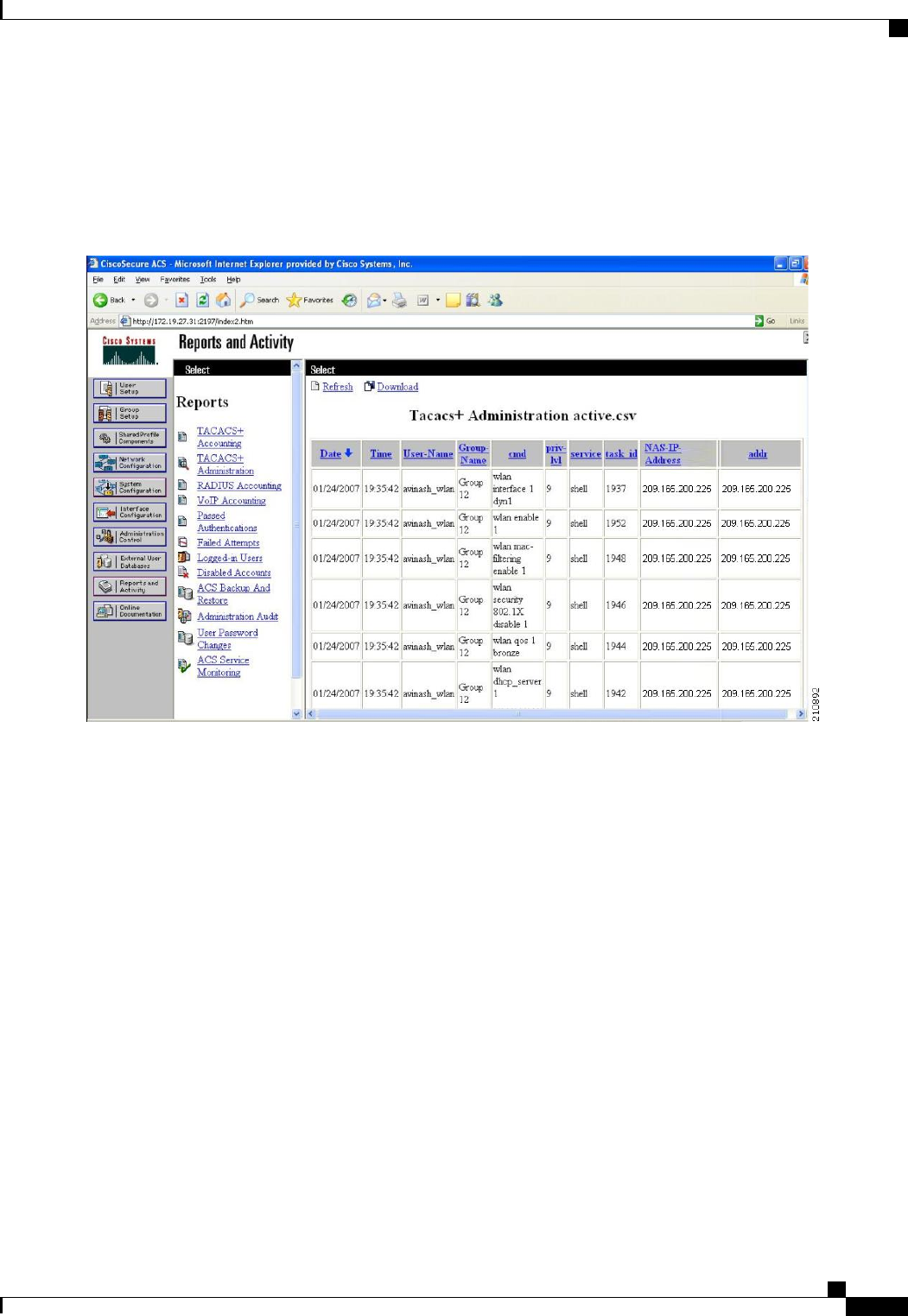
Click the .csv file corresponding to the date of the logs you want to view. The TACACS+ Administration .csv page
appears.
Figure 40: TACACS+ Administration .csv Page on CiscoSecure ACS
This page displays the following information:
•Date and time the action was taken
•Name and assigned role of the user who took the action
•Group to which the user belongs
•Specific action that the user took
•Privilege level of the user who executed the action
•IP address of the controller
•IP address of the laptop or workstation from which the action was executed
Sometimes a single action (or command) is logged multiple times, once for each parameter in the command. For example,
if you enter the snmp community ipaddr ip_address subnet_mask community_name command, the IP address may be
logged on one line while the subnet mask and community name are logged as “E.”On another line, the subnet mask
Cisco Wireless LAN Controller Configuration Guide, Release 7.4
OL-28744-01 381
Viewing the TACACS+ Administration Server Logs
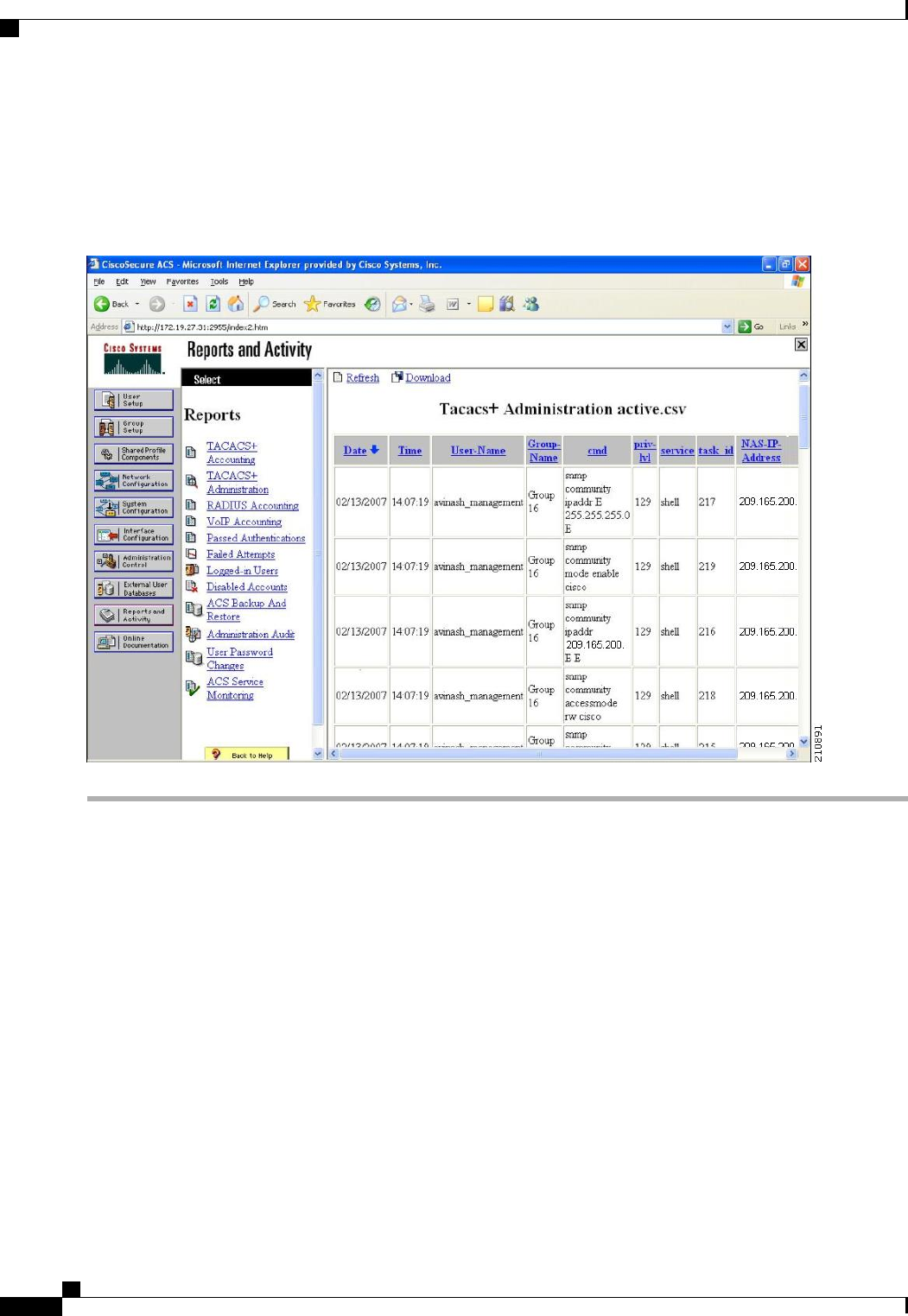
maybe logged while the IP address and community name are logged as “E.”See the first and third lines in the example
in this figure.
Figure 41: TACACS+ Administration .csv Page on CiscoSecure ACS
Cisco Wireless LAN Controller Configuration Guide, Release 7.4
382 OL-28744-01
Viewing the TACACS+ Administration Server Logs

CHAPTER 43
Configuring Maximum Local Database Entries
•Information About Configuring Maximum Local Database Entries, page 383
•Configuring Maximum Local Database Entries (GUI), page 383
•Configuring Maximum Local Database Entries (CLI), page 384
Information About Configuring Maximum Local Database Entries
You can configure the controller to specify the maximum number of local database entries used for storing
user authentication information. The database entries include local management users (including lobby
ambassadors), local network users (including guest users), MAC filter entries, exclusion list entries, and access
point authorization list entries. Together they cannot exceed the configured maximum value.
Configuring Maximum Local Database Entries (GUI)
Step 1 Choose Security >AAA >General to open the General page.
Step 2 In the Maximum Local Database Entries text box, enter a value for the maximum number of entries that can be added
to the local database the next time the controller reboots. The currently configured value appears in parentheses to the
right of the text box. The valid range is 512 to 2048, and the default setting is 2048.
The Number of Entries, Already Used text box shows the number of entries currently in the database.
Step 3 Click Apply to commit your changes.
Step 4 Click Save Configuration to save your settings.
Cisco Wireless LAN Controller Configuration Guide, Release 7.4
OL-28744-01 383

Configuring Maximum Local Database Entries (CLI)
Step 1 Specify the maximum number of entries that can be added to the local database the next time the controller reboots by
entering this command:
config database size max_entries
Step 2 Save your changes by entering this command:
save config
Step 3 View the maximum number of database entries and the current database contents by entering this command:
show database summary
Cisco Wireless LAN Controller Configuration Guide, Release 7.4
384 OL-28744-01
Configuring Maximum Local Database Entries (CLI)

CHAPTER 44
Configuring Local Network Users on the
Controller
•Information About Local Network Users on Controller, page 385
•Configuring Local Network Users for the Controller (GUI), page 385
•Configuring Local Network Users for the Controller (CLI), page 386
Information About Local Network Users on Controller
You can add local network users to the local user database on the controller. The local user database stores
the credentials (username and password) of all the local network users. These credentials are then used to
authenticate the users. For example, local EAP may use the local user database as its backend database to
retrieve user credentials.
The controller passes client information to the RADIUS authentication server first. If the client information
does not match a RADIUS database entry, the RADIUS authentication server replies with an authentication
failure message. If the RADIUS authentication server does not reply, then the local user database is queried.
Clients located in this database are granted access to network services if the RADIUS authentication fails
or does not exist.
Note
Configuring Local Network Users for the Controller (GUI)
Step 1 Choose Security >AAA >Local Net Users to open the Local Net Users page.
If you want to delete an existing user, hover your cursor over the blue drop-down arrow for that user and choose
Remove.
Note
Step 2 Perform one of the following:
•To edit an existing local network user, click the username for that user. The Local Net Users > Edit page appears.
Cisco Wireless LAN Controller Configuration Guide, Release 7.4
OL-28744-01 385

•To add a local network user, click New. The Local Net Users > New page appears.
Step 3 If you are adding a new user, enter a username for the local user in the User Name text box. You can enter up to 24
alphanumeric characters.
Local network usernames must be unique because they are all stored in the same database.Note
Step 4 In the Password and Confirm Password text boxes, enter a password for the local user. You can enter up to 24
alphanumeric characters.
Step 5 If you are adding a new user, select the Guest User check box if you want to limit the amount of time that the user has
access to the local network. The default setting is unselected.
Step 6 If you are adding a new user and you selected the Guest User check box, enter the amount of time (in seconds) that the
guest user account is to remain active in the Lifetime text box. The valid range is 60 to 2,592,000 seconds (30 days)
inclusive, and the default setting is 86,400 seconds.
Step 7 If you are adding a new user, you selected the Guest User check box, and you want to assign a QoS role to this guest
user, select the Guest User Role check box. The default setting is unselected.
If you do not assign a QoS role to a guest user, the bandwidth contracts for this user are defined in the QoS
profile for the WLAN.
Note
Step 8 If you are adding a new user and you selected the Guest User Role check box, choose the QoS role that you want to
assign to this guest user from the Role drop-down list.
Step 9 From the WLAN Profile drop-down list, choose the name of the WLAN that is to be accessed by the local user. If you
choose Any WLAN, which is the default setting, the user can access any of the configured WLANs.
Step 10 In the Description text box, enter a descriptive title for the local user (such as “User 1”).
Step 11 Click Apply to commit your changes.
Step 12 Click Save Configuration to save your changes.
Configuring Local Network Users for the Controller (CLI)
•Configure a local network user by entering these commands:
◦config netuser add username password wlan wlan_id userType permanent description
description—Adds a permanent user to the local user database on the controller.
◦config netuser add username password {wlan | guestlan} {wlan_id |guest_lan_id} userType
guestlifetime seconds description description—Adds a guest user on a WLAN or wired guest
LAN to the local user database on the controller.
Instead of adding a permanent user or a guest user to the local user database from the controller, you can
choose to create an entry on the RADIUS server for the user and enable RADIUS authentication for the
WLAN on which web authentication is performed.
Note
◦config netuser delete username—Deletes a user from the local user database on the controller.
Cisco Wireless LAN Controller Configuration Guide, Release 7.4
386 OL-28744-01
Configuring Local Network Users for the Controller (CLI)

Local network usernames must be unique because they are all stored in the same database.Note
•See information related to the local network users configured on the controller by entering these
commands:
◦show netuser detail username—Shows the configuration of a particular user in the local user
database.
◦show netuser summary—Lists all the users in the local user database.
•Save your changes by entering this command:
save config
Cisco Wireless LAN Controller Configuration Guide, Release 7.4
OL-28744-01 387
Configuring Local Network Users for the Controller (CLI)

Cisco Wireless LAN Controller Configuration Guide, Release 7.4
388 OL-28744-01
Configuring Local Network Users for the Controller (CLI)

CHAPTER 45
Configuring Password Policies
•Information About Password Policies, page 389
•Configuring Password Policies (GUI), page 390
•Configuring Password Policies (CLI), page 390
Information About Password Policies
The password policies allows you to enforce strong password checks on newly created passwords for additional
management users of controller and access point. The following are the requirements enforced on the new
password:
•When the controller is upgraded from old version, all the old passwords are maintained as it is, even
though the passwords are weak. After the system upgrade, if strong password checks are enabled, the
same is enforced from that time and the strength of previously added passwords will not be checked or
altered.
•Depending on the settings done in the Password Policy page, the local management and access point
user configuration is affected.
Cisco Wireless LAN Controller Configuration Guide, Release 7.4
OL-28744-01 389

Configuring Password Policies (GUI)
Step 1 Choose Security >AAA >Password Policies to open the Password Policies page.
Step 2 Select the Password must contain characters from at least 3 different classes check box if you want your password
to contain characters from at least three of the following classes: lower case letters, upper case letters, digits, and special
characters.
Step 3 Select the No character can be repeated more than 3 times consecutively check box if you do not want character in
the new password to repeat more than three times consecutively.
Step 4 Select the Password cannot be the default words like cisco, admin check box if you do not want the password to
contain words such as Cisco, ocsic, admin, nimda, or any variant obtained by changing the capitalization of letters or by
substituting 1, |, or! or substituting 0 for o or substituting $ for s.
Step 5 Select the Password cannot contain username or reverse of username check box if you do not want the password to
contain a username or the reverse letters of a username.
Step 6 Click Apply to commit your changes.
Step 7 Click Save Configuration to save your changes.
Configuring Password Policies (CLI)
•Enable or disable strong password check for AP and WLC by entering this command:
config switchconfig strong-pwd {case-check |consecutive-check |default-check |username-check
|all-checks} {enable |disable}
where
◦case-check—Checks the occurrence of same character thrice consecutively
◦consecutive-check—Checks the default values or its variants are being used.
◦default-check—Checks either username or its reverse is being used.
◦all-checks—Enables/disables all the strong password checks.
•See the configured options for strong password check by entering this command:
show switchconfig
Information similar to the following appears:
802.3x Flow Control Mode......................... Disabled
FIPS prerequisite features....................... Disabled
secret obfuscation............................... Enabled
Strong Password Check Features:
case-check ...........Enabled
consecutive-check ....Enabled
default-check .......Enabled
username-check ......Enabled
Cisco Wireless LAN Controller Configuration Guide, Release 7.4
390 OL-28744-01
Configuring Password Policies (GUI)

Cisco Wireless LAN Controller Configuration Guide, Release 7.4
OL-28744-01 391
Configuring Password Policies (CLI)

Cisco Wireless LAN Controller Configuration Guide, Release 7.4
392 OL-28744-01
Configuring Password Policies (CLI)

CHAPTER 46
Configuring LDAP
•Information About LDAP, page 393
•Configuring LDAP (GUI), page 394
•Configuring LDAP (CLI), page 396
Information About LDAP
An LDAP backend database allows the controller to query an LDAP server for the credentials (username and
password) of a particular user. These credentials are then used to authenticate the user. For example, local
EAP may use an LDAP server as its backend database to retrieve user credentials.
Fallback LDAP Servers
The LDAP servers are configured on a WLAN for authentication. You require at least two LDAP servers to
configure them for fallback behavior. A maximum of three LDAP servers can be configured for the fallback
behavior per WLAN. The servers are listed in the priority order for authentication. If the first LDAP server
becomes irresponsive, then the controller switches to the next LDAP server. If the second LDAP server
becomes irresponsive, then the controller switches again to the third LDAP server.
The LDAP backend database supports these local EAP methods: EAP-TLS, EAP-FAST/GTC, and
PEAPv1/GTC. LEAP, EAP-FAST/MSCHAPv2, and PEAPv0/MSCHAPv2 are also supported but only
if the LDAP server is set up to return a clear-text password.
Note
Cisco wireless LAN controllers support Local EAP authentication against external LDAP databases such
as Microsoft Active Directory and Novell’s eDirectory. For more information about configuring the
controller for Local EAP authentication against Novell’s eDirectory, see the Configure Unified Wireless
Network for Authentication Against Novell's eDirectory Database whitepaper at http://www.cisco.com/
en/US/products/ps6366/products_white_paper09186a0080b4cd24.shtml.
Note
Cisco Wireless LAN Controller Configuration Guide, Release 7.4
OL-28744-01 393

Configuring LDAP (GUI)
Step 1 Choose Security >AAA >LDAP to open the LDAP Servers page.
•If you want to delete an existing LDAP server, hover your cursor over the blue drop-down arrow for that server
and choose Remove.
•If you want to make sure that the controller can reach a particular server, hover your cursor over the blue drop-down
arrow for that server and choose Ping.
Step 2 Perform one of the following:
•To edit an existing LDAP server, click the index number for that server. The LDAP Servers > Edit page appears.
•To add an LDAP server, click New. The LDAP Servers > New page appears. If you are adding a new server,
choose a number from the Server Index (Priority) drop-down list to specify the priority order of this server in
relation to any other configured LDAP servers. You can configure up to 17 servers. If the controller cannot reach
the first server, it tries the second one in the list and so on.
Step 3 If you are adding a new server, enter the IP address of the LDAP server in the Server IP Address text box.
Step 4 If you are adding a new server, enter the LDAP server’s TCP port number in the Port Number text box. The valid range
is 1 to 65535, and the default value is 389.
Step 5 From the Server Mode drop-down list, choose None.
Step 6 Select the Enable Server Status check box to enable this LDAP server or unselect it to disable it. The default value is
disabled.
Step 7 From the Simple Bind drop-down list, choose Anonymous or Authenticated to specify the local authentication bind
method for the LDAP server. The Anonymous method allows anonymous access to the LDAP server. The Authenticated
method requires that a username and password be entered to secure access. The default value is Anonymous.
Step 8 If you chose Authenticated in the previous step, follow these steps:
a) In the Bind Username text box, enter a username to be used for local authentication to the LDAP server. The username
can contain up to 80 characters.
If the username starts with “cn=”(in lowercase letters), the controller assumes that the username includes
the entire LDAP database path and does not append the user base DN. This designation allows the
authenticated bind user to be outside the user base DN.
Note
b) In the Bind Username text box, enter a username to be used for local authentication to the LDAP server. The username
can contain up to 80 characters.
Step 9 In the User Base DN text box, enter the distinguished name (DN) of the subtree in the LDAP server that contains a list
of all the users. For example, ou=organizational unit, .ou=next organizational unit, and o=corporation.com. If the tree
containing users is the base DN, type.
o=corporation.com
or
Cisco Wireless LAN Controller Configuration Guide, Release 7.4
394 OL-28744-01
Configuring LDAP (GUI)

dc=corporation,dc=com
Step 10 In the User Attribute text box, enter the name of the attribute in the user record that contains the username. You can
obtain this attribute from your directory server.
Step 11 In the User Object Type text box, enter the value of the LDAP objectType attribute that identifies the record as a user.
Often, user records have several values for the objectType attribute, some of which are unique to the user and some of
which are shared with other object types.
Step 12 In the Server Timeout text box, enter the number of seconds between retransmissions. The valid range is 2 to 30 seconds,
and the default value is 2 seconds.
Step 13 Click Apply to commit your changes.
Step 14 Click Save Configuration to save your changes.
Step 15 Specify LDAP as the priority backend database server for local EAP authentication as follows:
a) Choose Security >Local EAP >Authentication Priority to open the Priority Order > Local-Auth page.
b) Highlight LOCAL and click <to move it to the left User Credentials box.
c) Highlight LDAP and click >to move it to the right User Credentials box. The database that appears at the top of the
right User Credentials box is used when retrieving user credentials.
If both LDAP and LOCAL appear in the right User Credentials box with LDAP on the top and LOCAL on
the bottom, local EAP attempts to authenticate clients using the LDAP backend database and fails over to
the local user database if the LDAP servers are not reachable. If the user is not found, the authentication
attempt is rejected. If LOCAL is on the top, local EAP attempts to authenticate using only the local user
database. It does not fail over to the LDAP backend database.
Note
d) Click Apply to commit your changes.
e) Click Save Configuration to save your changes.
Step 16 (Optional) Assign specific LDAP servers to a WLAN as follows:
a) Choose WLANs to open the WLANs page.
b) Click the ID number of the desired WLAN.
c) When the WLANs > Edit page appears, choose the Security >AAA Servers tabs to open the WLANs > Edit (Security
> AAA Servers) page.
d) From the LDAP Servers drop-down lists, choose the LDAP server(s) that you want to use with this WLAN. You can
choose up to three LDAP servers, which are tried in priority order.
These LDAP servers apply only to WLANs with web authentication enabled. They are not used by local
EAP.
Note
e) Click Apply to commit your changes.
f) Click Save Configuration to save your changes.
Step 17 Specify the LDAP server fallback behavior, as follows:
a) Choose WLAN >AAA Server to open the Fallback Parameters page.
b) From the LDAP Servers drop-down list, choose the LDAP server in the order of priority when the controller attempts
to authenticate management users. The order of authentication is from server.
c) Choose Security >AAA >LDAP to view the list of global LDAP servers configured for the controller.
Cisco Wireless LAN Controller Configuration Guide, Release 7.4
OL-28744-01 395
Configuring LDAP (GUI)

Configuring LDAP (CLI)
•Configure an LDAP server by entering these commands:
◦config ldap add index server_ip_address port# user_base user_attr user_type —Adds an LDAP
server.
◦config ldap delete index—Deletes a previously added LDAP server.
◦config ldap {enable |disable}index—Enables or disables an LDAP server.
◦config ldap simple-bind {anonymous index |authenticated index username username password
password}—Specifies the local authentication bind method for the LDAP server. The anonymous
method allows anonymous access to the LDAP server whereas the authenticated method requires
that a username and password be entered to secure access. The default value is anonymous. The
username can contain up to 80 characters.
If the username starts with “cn=”(in lowercase letters), the controller assumes that the username
includes the entire LDAP database path and does not append the user base DN. This designation
allows the authenticated bind user to be outside the user base DN.
◦config ldap retransmit-timeout index timeout—Configures the number of seconds between
retransmissions for an LDAP server.
•Specify LDAP as the priority backend database server by entering this command:
config local-auth user-credentials ldap
If you enter the config local-auth user-credentials ldap local command, local EAP attempts to
authenticate clients using the LDAP backend database and fails over to the local user database if the
LDAP servers are not reachable. If the user is not found, the authentication attempt is rejected. If you
enter the config local-auth user-credentials local ldap command, local EAP attempts to authenticate
using only the local user database. It does not fail over to the LDAP backend database.
•(Optional) Assign specific LDAP servers to a WLAN by entering these commands:
◦config wlan ldap add wlan_id server_index—Links a configured LDAP server to a WLAN.
The LDAP servers specified in this command apply only to WLANs with web authentication
enabled. They are not used by local EAP.
◦config wlan ldap delete wlan_id {all |index}—Deletes a specific or all configured LDAP server(s)
from a WLAN.
•View information pertaining to configured LDAP servers by entering these commands:
◦show ldap summary—Shows a summary of the configured LDAP servers.
Idx Server Address Port Enabled
--- --------------- ---- -------
1 2.3.1.4 389 No
2 10.10.20.22 389 Yes
◦show ldap index—Shows detailed LDAP server information. Information like the following
appears:
Server Index..................................... 2
Address.......................................... 10.10.20.22
Port............................................. 389
Cisco Wireless LAN Controller Configuration Guide, Release 7.4
396 OL-28744-01
Configuring LDAP (CLI)

Enabled.......................................... Yes
User DN.......................................... ou=active,ou=employees,ou=people,
o=cisco.com
User Attribute................................... uid
User Type........................................ Person
Retransmit Timeout............................... 2 seconds
Bind Method ..................................... Authenticated
Bind Username................................. user1
◦show ldap statistics—Shows LDAP server statistics.
Server Index..................................... 1
Server statistics:
Initialized OK................................. 0
Initialization failed.......................... 0
Initialization retries......................... 0
Closed OK...................................... 0
Request statistics:
Received....................................... 0
Sent........................................... 0
OK............................................. 0
Success........................................ 0
Authentication failed.......................... 0
Server not found............................... 0
No received attributes......................... 0
No passed username............................. 0
Not connected to server........................ 0
Internal error................................. 0
Retries........................................ 0
Server Index..................................... 2
..
◦show wlan wlan_id—Shows the LDAP servers that are applied to a WLAN.
•Make sure the controller can reach the LDAP server by entering this command:
ping server_ip_address
•Save your changes by entering this command:
save config
•Enable or disable debugging for LDAP by entering this command:
debug aaa ldap {enable | disable}
Cisco Wireless LAN Controller Configuration Guide, Release 7.4
OL-28744-01 397
Configuring LDAP (CLI)

Cisco Wireless LAN Controller Configuration Guide, Release 7.4
398 OL-28744-01
Configuring LDAP (CLI)

CHAPTER 47
Configuring Local EAP
•Information About Local EAP, page 399
•Restrictions for Local EAP, page 400
•Configuring Local EAP (GUI), page 401
•Configuring Local EAP (CLI), page 404
Information About Local EAP
Local EAP is an authentication method that allows users and wireless clients to be authenticated locally. It is
designed for use in remote offices that want to maintain connectivity to wireless clients when the backend
system becomes disrupted or the external authentication server goes down. When you enable local EAP, the
controller serves as the authentication server and the local user database, which removes dependence on an
external authentication server. Local EAP retrieves user credentials from the local user database or the LDAP
backend database to authenticate users. Local EAP supports LEAP, EAP-FAST, EAP-TLS, P
EAPv0/MSCHAPv2, and PEAPv1/GTC authentication between the controller and wireless clients.
The LDAP backend database supports these local EAP methods: EAP-TLS, EAP-FAST/GTC, and
PEAPv1/GTC. LEAP, EAP-FAST/MSCHAPv2, and PEAPv0/MSCHAPv2 are also supported but only
if the LDAP server is set up to return a clear-text password.
Note
Cisco wireless LAN controllers support Local EAP authentication against external LDAP databases such
as Microsoft Active Directory and Novell’s eDirectory. For more information about configuring the
controller for Local EAP authentication against Novell’s eDirectory, see the Configure Unified Wireless
Network for Authentication Against Novell's eDirectory Database whitepaper at http://www.cisco.com/
en/US/products/ps6366/products_white_paper09186a0080b4cd24.shtml.
Note
If any RADIUS servers are configured on the controller, the controller tries to authenticate the wireless clients
using the RADIUS servers first. Local EAP is attempted only if no RADIUS servers are found, either because
the RADIUS servers timed out or no RADIUS servers were configured. If four RADIUS servers are configured,
the controller attempts to authenticate the client with the first RADIUS server, then the second RADIUS
server, and then local EAP. If the client attempts to then reauthenticate manually, the controller tries the third
Cisco Wireless LAN Controller Configuration Guide, Release 7.4
OL-28744-01 399

RADIUS server, then the fourth RADIUS server, and then local EAP. If you never want the controller to try
to authenticate clients using an external RADIUS server, enter these CLI commands in this order:
•config wlan disable wlan_id
•config wlan radius_server auth disable wlan_id
•config wlan enable wlan_id
Figure 42: Local EAP Example
Restrictions for Local EAP
Local EAP profiles are not supported on Cisco 600 Series OfficeExtend access points.
Cisco Wireless LAN Controller Configuration Guide, Release 7.4
400 OL-28744-01
Restrictions for Local EAP

Configuring Local EAP (GUI)
Before You Begin
EAP-TLS, P EAPv0/MSCHAPv2, and PEAPv1/GTC use certificates for authentication, and EAP-FAST
uses either certificates or PACs. The controller is shipped with Cisco-installed device and Certificate
Authority (CA) certificates. However, if you want to use your own vendor-specific certificates, they must
be imported on the controller.
Note
Step 1 If you are configuring local EAP to use one of the EAP types listed in the note above, make sure that the appropriate
certificates and PACs (if you will use manual PAC provisioning) have been imported on the controller.
Step 2 If you want the controller to retrieve user credentials from the local user database, make sure that you have properly
configured the local network users on the controller.
Step 3 If you want the controller to retrieve user credentials from an LDAP backend database, make sure that you have properly
configured an LDAP server on the controller.
Step 4 Specify the order in which user credentials are retrieved from the backend database servers as follows:
a) Choose Security >Local EAP >Authentication Priority to open the Priority Order > Local-Auth page.
b) Determine the priority order in which user credentials are to be retrieved from the local and/or LDAP databases. For
example, you may want the LDAP database to be given priority over the local user database, or you may not want
the LDAP database to be considered at all.
c) When you have decided on a priority order, highlight the desired database. Then use the left and right arrows and
the Up and Down buttons to move the desired database to the top of the right User Credentials box.
If both LDAP and LOCAL appear in the right User Credentials box with LDAP on the top and LOCAL on
the bottom, local EAP attempts to authenticate clients using the LDAP backend database and fails over to
the local user database if the LDAP servers are not reachable. If the user is not found, the authentication
attempt is rejected. If LOCAL is on the top, local EAP attempts to authenticate using only the local user
database. It does not fail over to the LDAP backend database.
Note
d) Click Apply to commit your changes.
Step 5 Specify values for the local EAP timers as follows:
a) Choose Security >Local EAP >General to open the General page.
b) In the Local Auth Active Timeout text box, enter the amount of time (in seconds) in which the controller attempts
to authenticate wireless clients using local EAP after any pair of configured RADIUS servers fails. The valid range
is 1 to 3600 seconds, and the default setting is 100 seconds.
c) In the Identity Request Timeout text box, enter the amount of time (in seconds) in which the controller attempts to
send an EAP identity request to wireless clients using local EAP. The valid range is 1 to 120 seconds, and the default
setting is 30 seconds.
d) In the Identity Request Max Retries text box, enter the maximum number of times that the controller attempts to
retransmit the EAP identity request to wireless clients using local EAP. The valid range is 1 to 20 retries, and the
default setting is 20 retries.
e) In the Dynamic WEP Key Index text box, enter the key index used for dynamic wired equivalent privacy (WEP).
The default value is 0, which corresponds to a key index of 1; the valid values are 0 to 3 (key index of 1 to 4).
Cisco Wireless LAN Controller Configuration Guide, Release 7.4
OL-28744-01 401
Configuring Local EAP (GUI)

f) In the Request Timeout text box, enter the amount of time (in seconds) in which the controller attempts to send an
EAP request to wireless clients using local EAP. The valid range is 1 to 120 seconds, and the default setting is 30
seconds.
g) In the Request Max Retries text box, enter the maximum number of times that the controller attempts to retransmit
the EAP request to wireless clients using local EAP. The valid range is 1 to 120 retries, and the default setting is 20
retries.
h) From the Max-Login Ignore Identity Response drop-down list, choose Enable to limit the number of devices that
can be connected to the controller with the same username. You can log in up to eight times from different devices
(PDA, laptop, IP phone, and so on) on the same controller. The default value is enabled.
i) In the EAPOL-Key Timeout text box, enter the amount of time (in seconds) in which the controller attempts to send
an EAP key over the LAN to wireless clients using local EAP. The valid range is 1 to 5 seconds, and the default
setting is 1 second.
If the controller and access point are separated by a WAN link, the default timeout of 1 second may not be
sufficient.
Note
j) In the EAPOL-Key Max Retries text box, enter the maximum number of times that the controller attempts to send
an EAP key over the LAN to wireless clients using local EAP. The valid range is 0 to 4 retries, and the default setting
is 2 retries.
k) Click Apply to commit your changes.
Step 6 Create a local EAP profile, which specifies the EAP authentication types that are supported on the wireless clients as
follows:
a) Choose Security >Local EAP >Profiles to open the Local EAP Profiles page.
This page lists any local EAP profiles that have already been configured and specifies their EAP types. You can
create up to 16 local EAP profiles.
If you want to delete an existing profile, hover your cursor over the blue drop-down arrow for that profile
and choose Remove.
Note
b) Click New to open the Local EAP Profiles > New page.
c) In the Profile Name text box, enter a name for your new profile and then click Apply.
You can enter up to 63 alphanumeric characters for the profile name. Make sure not to include spaces.Note
d) When the Local EAP Profiles page reappears, click the name of your new profile. The Local EAP Profiles > Edit
page appears.
e) Select the LEAP,EAP-FAST,EAP-TLS, and/or PEAP check boxes to specify the EAP type that can be used for
local authentication.
You can specify more than one EAP type per profile. However, if you choose multiple EAP types that use
certificates (such as EAP-FAST with certificates, EAP-TLS, PEAPv0/MSCHAPv2, and PEAPv1/GTC), all
of the EAP types must use the same certificate (from either Cisco or another vendor).
Note
If you select the PEAP check box, both PEAPv0/MSCHAPv2 or PEAPv1/GTC are enabled on the controller.Note
f) If you chose EAP-FAST and want the device certificate on the controller to be used for authentication, select the
Local Certificate Required check box. If you want to use EAP-FAST with PACs instead of certificates, leave this
check box unselected, which is the default setting.
This option applies only to EAP-FAST because device certificates are not used with LEAP and are mandatory
for EAP-TLS and PEAP.
Note
g) If you chose EAP-FAST and want the wireless clients to send their device certificates to the controller in order to
authenticate, select the Client Certificate Required check box. If you want to use EAP-FAST with PACs instead
of certificates, leave this check box unselected, which is the default setting.
Cisco Wireless LAN Controller Configuration Guide, Release 7.4
402 OL-28744-01
Configuring Local EAP (GUI)

This option applies only to EAP-FAST because client certificates are not used with LEAP or PEAP and are
mandatory for EAP-TLS.
Note
h) If you chose EAP-FAST with certificates, EAP-TLS, or PEAP, choose which certificates will be sent to the client,
the ones from Cisco or the ones from another Vendor, from the Certificate Issuer drop-down list. The default setting
is Cisco.
i) If you chose EAP-FAST with certificates or EAP-TLS and want the incoming certificate from the client to be validated
against the CA certificates on the controller, select the Check against CA certificates check box. The default setting
is enabled.
j) If you chose EAP-FAST with certificates or EAP-TLS and want the common name (CN) in the incoming certificate
to be validated against the CA certificates’CN on the controller, select the Verify Certificate CN Identity check
box. The default setting is disabled.
k) If you chose EAP-FAST with certificates or EAP-TLS and want the controller to verify that the incoming device
certificate is still valid and has not expired, select the Check Certificate Date Validity check box. The default setting
is enabled.
Certificate date validity is checked against the current UTC (GMT) time that is configured on the controller.
Timezone offset will be ignored.
Note
l) Click Apply to commit your changes.
Step 7 If you created an EAP-FAST profile, follow these steps to configure the EAP-FAST parameters:
a) Choose Security >Local EAP >EAP-FAST Parameters to open the EAP-FAST Method Parameters page.
b) In the Server Key and Confirm Server Key text boxes, enter the key (in hexadecimal characters) used to encrypt and
decrypt PACs.
c) In the Time to Live for the PAC text box, enter the number of days for the PAC to remain viable. The valid range is
1 to 1000 days, and the default setting is 10 days.
d) In the Authority ID text box, enter the authority identifier of the local EAP-FAST server in hexadecimal characters.
You can enter up to 32 hexadecimal characters, but you must enter an even number of characters.
e) In the Authority ID Information text box, enter the authority identifier of the local EAP-FAST server in text format.
f) If you want to enable anonymous provisioning, select the Anonymous Provision check box. This feature allows
PACs to be sent automatically to clients that do not have one during PAC provisioning. If you disable this feature,
PACS must be manually provisioned. The default setting is enabled.
If the local and/or client certificates are required and you want to force all EAP-FAST clients to use
certificates, unselect the Anonymous Provision check box.
Note
g) Click Apply to commit your changes.
Step 8 Enable local EAP on a WLAN as follows:
a) Choose WLANs to open the WLANs page.
b) Click the ID number of the desired WLAN.
c) When the WLANs > Edit page appears, choose the Security >AAA Servers tabs to open the WLANs > Edit
(Security > AAA Servers) page.
d) Select the Local EAP Authentication check box to enable local EAP for this WLAN.
e) From the EAP Profile Name drop-down list, choose the EAP profile that you want to use for this WLAN.
f) If desired, choose the LDAP server that you want to use with local EAP on this WLAN from the LDAP Servers
drop-down lists.
g) Click Apply to commit your changes.
Step 9 Click Save Configuration to save your changes.
Cisco Wireless LAN Controller Configuration Guide, Release 7.4
OL-28744-01 403
Configuring Local EAP (GUI)

Configuring Local EAP (CLI)
Before You Begin
EAP-TLS, P EAPv0/MSCHAPv2, and PEAPv1/GTC use certificates for authentication, and EAP-FAST
uses either certificates or PACbs. The controller is shipped with Cisco-installed device and Certificate
Authority (CA) certificates. However, if you want to use your own vendor-specific certificates, they must
be imported on the controller.
Note
Step 1 If you are configuring local EAP to use one of the EAP types listed in the note above, make sure that the appropriate
certificates and PACs (if you will use manual PAC provisioning) have been imported on the controller.
Step 2 If you want the controller to retrieve user credentials from the local user database, make sure that you have properly
configured the local network users on the controller.
Step 3 If you want the controller to retrieve user credentials from an LDAP backend database, make sure that you have properly
configured an LDAP server on the controller.
Step 4 Specify the order in which user credentials are retrieved from the local and/or LDAP databases by entering this command:
config local-auth user-credentials {local |ldap}
If you enter the config local-auth user-credentials ldap local command, local EAP attempts to authenticate
clients using the LDAP backend database and fails over to the local user database if the LDAP servers are not
reachable. If the user is not found, the authentication attempt is rejected. If you enter the config local-auth
user-credentials local ldap command, local EAP attempts to authenticate using only the local user database.
It does not fail over to the LDAP backend database.
Note
Step 5 Specify values for the local EAP timers by entering these commands:
•config local-auth active-timeout timeout—Specifies the amount of time (in seconds) in which the controller
attempts to authenticate wireless clients using local EAP after any pair of configured RADIUS servers fails. The
valid range is 1 to 3600 seconds, and the default setting is 100 seconds.
•config advanced eap identity-request-timeout timeout—Specifies the amount of time (in seconds) in which the
controller attempts to send an EAP identity request to wireless clients using local EAP. The valid range is 1 to 120
seconds, and the default setting is 30 seconds.
•config advanced eap identity-request-retries retries—Specifies the maximum number of times that the controller
attempts to retransmit the EAP identity request to wireless clients using local EAP. The valid range is 1 to 20 retries,
and the default setting is 20 retries.
•config advanced eap key-index index—Specifies the key index used for dynamic wired equivalent privacy (WEP).
The default value is 0, which corresponds to a key index of 1; the valid values are 0 to 3 (key index of 1 to 4).
•config advanced eap request-timeout timeout—Specifies the amount of time (in seconds) in which the controller
attempts to send an EAP request to wireless clients using local EAP. The valid range is 1 to 120 seconds, and the
default setting is 30 seconds.
•config advanced eap request-retries retries—Specifies the maximum number of times that the controller attempts
to retransmit the EAP request to wireless clients using local EAP. The valid range is 1 to 120 retries, and the default
setting is 20 retries.
Cisco Wireless LAN Controller Configuration Guide, Release 7.4
404 OL-28744-01
Configuring Local EAP (CLI)

•config advanced eap eapol-key-timeout timeout—Specifies the amount of time (in seconds) in which the controller
attempts to send an EAP key over the LAN to wireless clients using local EAP. The valid range is 1 to 5 seconds,
and the default setting is 1 second.
If the controller and access point are separated by a WAN link, the default timeout of 1 second may not
be sufficient.
Note
•config advanced eap eapol-key-retries retries—Specifies the maximum number of times that the controller
attempts to send an EAP key over the LAN to wireless clients using local EAP. The valid range is 0 to 4 retries,
and the default setting is 2 retries.
•config advanced eap max-login-ignore-identity-response {enable |disable}—When enabled, this command
limits the number of devices that can be connected to the controller with the same username. You can log in up to
eight times from different devices (PDA, laptop, IP phone, and so on) on the same controller. The default value is
enabled.
Step 6 Create a local EAP profile by entering this command:
config local-auth eap-profile add profile_name
Do not include spaces within the profile
name.
Note
To delete a local EAP profile, enter the config local-auth eap-profile delete profile_name command.
Note
Step 7 Add an EAP method to a local EAP profile by entering this command:
config local-auth eap-profile method add method profile_name
The supported methods are leap, fast, tls, and peap.
If you choose peap, both P EAPv0/MSCHAPv2 or PEAPv1/GTC are enabled on the controller.Note
You can specify more than one EAP type per profile. However, if you create a profile with multiple EAP types
that use certificates (such as EAP-FAST with certificates, EAP-TLS, PEAPv0/MSCHAPv2, and PEAPv1/GTC),
all of the EAP types must use the same certificate (from either Cisco or another vendor).
Note
To delete an EAP method from a local EAP profile, enter the config local-auth eap-profile method delete
method profile_name command:
Note
Step 8 Configure EAP-FAST parameters if you created an EAP-FAST profile by entering this command:
config local-auth method fast ?
where ?is one of the following:
•anon-prov {enable |disable}—Configures the controller to allow anonymous provisioning, which allows PACs
to be sent automatically to clients that do not have one during PAC provisioning.
•authority-id auth_id—Specifies the authority identifier of the local EAP-FAST server.
•pac-ttl days—Specifies the number of days for the PAC to remain viable.
•server-key key—Specifies the server key used to encrypt and decrypt PACs.
Step 9 Configure certificate parameters per profile by entering these commands:
•config local-auth eap-profile method fast local-cert {enable |disable}profile_name—Specifies whether the
device certificate on the controller is required for authentication.
This command applies only to EAP-FAST because device certificates are not used with LEAP and are
mandatory for EAP-TLS and PEAP.
Note
Cisco Wireless LAN Controller Configuration Guide, Release 7.4
OL-28744-01 405
Configuring Local EAP (CLI)

•config local-auth eap-profile method fast client-cert {enable |disable}profile_name—Specifies whether
wireless clients are required to send their device certificates to the controller in order to authenticate.
This command applies only to EAP-FAST because client certificates are not used with LEAP or PEAP
and are mandatory for EAP-TLS.
Note
•config local-auth eap-profile cert-issuer {cisco |vendor}profile_name—If you specified EAP-FAST with
certificates, EAP-TLS, or PEAP, specifies whether the certificates that will be sent to the client are from Cisco or
another vendor.
•config local-auth eap-profile cert-verify ca-issuer {enable |disable}profile_name—If you chose EAP-FAST
with certificates or EAP-TLS, specifies whether the incoming certificate from the client is to be validated against
the CA certificates on the controller.
•config local-auth eap-profile cert-verify cn-verify {enable |disable}profile_name—If you chose EAP-FAST
with certificates or EAP-TLS, specifies whether the common name (CN) in the incoming certificate is to be validated
against the CA certificates’CN on the controller.
•config local-auth eap-profile cert-verify date-valid {enable |disable}profile_name—If you chose EAP-FAST
with certificates or EAP-TLS, specifies whether the controller is to verify that the incoming device certificate is
still valid and has not expired.
Step 10 Enable local EAP and attach an EAP profile to a WLAN by entering this command:
config wlan local-auth enable profile_name wlan_id
To disable local EAP for a WLAN, enter the config wlan local-auth disable wlan_id command.
Note
Step 11 Save your changes by entering this command:
save config
Step 12 View information pertaining to local EAP by entering these commands:
•show local-auth config—Shows the local EAP configuration on the controller.
User credentials database search order:
Primary ..................................... Local DB
Timer:
Active timeout .............................. 300
Configured EAP profiles:
Name ........................................ fast-cert
Certificate issuer ........................ vendor
Peer verification options:
Check against CA certificates ........... Enabled
Verify certificate CN identity .......... Disabled
Check certificate date validity ......... Enabled
EAP-FAST configuration:
Local certificate required .............. Yes
Client certificate required ............. Yes
Enabled methods ........................... fast
Configured on WLANs ....................... 1
Name ........................................ tls
Certificate issuer ........................ vendor
Peer verification options:
Check against CA certificates ........... Enabled
Verify certificate CN identity .......... Disabled
Check certificate date validity ......... Enabled
EAP-FAST configuration:
Local certificate required .............. No
Client certificate required ............. No
Cisco Wireless LAN Controller Configuration Guide, Release 7.4
406 OL-28744-01
Configuring Local EAP (CLI)

Enabled methods ........................... tls
Configured on WLANs ....................... 2
EAP Method configuration:
EAP-FAST:
Server key ................................ <hidden>
TTL for the PAC ........................... 10
Anonymous provision allowed ............... Yes
Accept client on auth prov ................ No
Authority ID .............................. 436973636f0000000000000000000000
Authority Information ..................... Cisco A-ID
•show local-auth statistics—Shows the local EAP statistics.
•show local-auth certificates—Shows the certificates available for local EAP.
•show local-auth user-credentials—Shows the priority order that the controller uses when retrieving user credentials
from the local and/or LDAP databases.
•show advanced eap—Shows the timer values for local EAP.
EAP-Identity-Request Timeout (seconds)........... 1
EAP-Identity-Request Max Retries................. 20
EAP Key-Index for Dynamic WEP.................... 0
EAP Max-Login Ignore Identity Response........... enable
EAP-Request Timeout (seconds).................... 20
EAP-Request Max Retries.......................... 20
EAPOL-Key Timeout (seconds)...................... 1
EAPOL-Key Max Retries......................... 2
•show ap stats wlan Cisco_AP—Shows the EAP timeout and failure counters for a specific access point for each
WLAN.
•show client detail client_mac—Shows the EAP timeout and failure counters for a specific associated client. These
statistics are useful in troubleshooting client association issues.
...
Client Statistics:
Number of Bytes Received................... 10
Number of Bytes Sent....................... 10
Number of Packets Received................. 2
Number of Packets Sent..................... 2
Number of EAP Id Request Msg Timeouts...... 0
Number of EAP Id Request Msg Failures...... 0
Number of EAP Request Msg Timeouts......... 2
Number of EAP Request Msg Failures......... 1
Number of EAP Key Msg Timeouts............. 0
Number of EAP Key Msg Failures............. 0
Number of Policy Errors.................... 0
Radio Signal Strength Indicator............ Unavailable
Signal to Noise Ratio...................... Unavailable
•show wlan wlan_id—Shows the status of local EAP on a particular WLAN.
Step 13 (Optional) Troubleshoot local EAP sessions by entering these commands:
•debug aaa local-auth eap method {all |errors |events |packets |sm} {enable |disable}—Enables or disables
debugging of local EAP methods.
•debug aaa local-auth eap framework {all |errors |events |packets |sm} {enable |disable}—Enables or
disables debugging of the local EAP framework.
In these two debug commands, sm is the state
machine.
Note
Cisco Wireless LAN Controller Configuration Guide, Release 7.4
OL-28744-01 407
Configuring Local EAP (CLI)

•clear stats local-auth—Clears the local EAP counters.
•clear stats ap wlan Cisco_AP—Clears the EAP timeout and failure counters for a specific access point for each
WLAN.
WLAN 1
EAP Id Request Msg Timeouts................... 0
EAP Id Request Msg Timeouts Failures.......... 0
EAP Request Msg Timeouts...................... 2
EAP Request Msg Timeouts Failures............. 1
EAP Key Msg Timeouts.......................... 0
EAP Key Msg Timeouts Failures................. 0
WLAN 2
EAP Id Request Msg Timeouts................... 1
EAP Id Request Msg Timeouts Failures.......... 0
EAP Request Msg Timeouts...................... 0
EAP Request Msg Timeouts Failures............. 0
EAP Key Msg Timeouts.......................... 3
EAP Key Msg Timeouts Failures.............. 1
Cisco Wireless LAN Controller Configuration Guide, Release 7.4
408 OL-28744-01
Configuring Local EAP (CLI)

CHAPTER 48
Configuring the System for SpectraLink NetLink
Telephones
•Information About SpectraLink NetLink Telephones, page 409
•Configuring SpectraLink NetLink Phones, page 409
Information About SpectraLink NetLink Telephones
For the best integration with the Cisco UWN solution, SpectraLink NetLink Telephones require an extra
operating system configuration step: enable long preambles. The radio preamble (sometimes called a header)
is a section of data at the head of a packet that contains information that wireless devices need when sending
and receiving packets. Short preambles improve throughput performance, so they are enabled by default.
However, some wireless devices, such as SpectraLink NetLink phones, require long preambles.
Configuring SpectraLink NetLink Phones
Enabling Long Preambles (GUI)
Step 1 Choose Wireless >802.11b/g/n >Network to open the 802.11b/g Global Parameters page.
Step 2 If the Short Preamble check box is selected, continue with this procedure. However, if the Short Preamble check box
is unselected (which means that long preambles are enabled), the controller is already optimized for SpectraLink NetLink
phones and you do not need to continue this procedure.
Step 3 Unselect the Short Preamble check box to enable long preambles.
Step 4 Click Apply to update the controller configuration.
If you do not already have an active CLI session to the controller, we recommend that you start a CLI session
to reboot the controller and watch the reboot process. A CLI session is also useful because the GUI loses its
connection when the controller reboots.
Note
Cisco Wireless LAN Controller Configuration Guide, Release 7.4
OL-28744-01 409

Step 5 Choose Commands >Reboot >Reboot > Save and Reboot to reboot the controller. Click OK in response to this
prompt:
Configuration will be saved and the controller will be rebooted. Click ok to confirm.
The controller reboots.
Step 6 Log back onto the controller GUI to verify that the controller is properly configured.
Step 7 Choose Wireless >802.11b/g/n >Network to open the 802.11b/g Global Parameters page. If the Short Preamble check
box is unselected, the controller is optimized for SpectraLink NetLink phones.
Enabling Long Preambles (CLI)
Step 1 Log on to the controller CLI.
Step 2 Enter the show 802.11b command and select the Short preamble mandatory parameter. If the parameter indicates that
short preambles are enabled, continue with this procedure. This example shows that short preambles are enabled:
Short Preamble mandatory....................... Enabled
However, if the parameter shows that short preambles are disabled (which means that long preambles are enabled), the
controller is already optimized for SpectraLink NetLink phones and you do not need to continue this procedure.
Step 3 Disable the 802.11b/g network by entering this command:
config 802.11b disable network
You cannot enable long preambles on the 802.11a network.
Step 4 Enable long preambles by entering this command:
config 802.11b preamble long
Step 5 Reenable the 802.11b/g network by entering this command:
config 802.11b enable network
Step 6 Enter the reset system command to reboot the controller. Enter y when the prompt to save the system changes is displayed.
The controller reboots.
Step 7 Verify that the controller is properly configured by logging back into the CLI and entering the show 802.11b command
to view these parameters:
802.11b Network................................ Enabled
Short Preamble mandatory....................... Disabled
These parameters show that the 802.11b/g network is enabled and that short preambles are disabled.
Configuring Enhanced Distributed Channel Access (CLI)
To configure 802.11 enhanced distributed channel access (EDCA) parameters to support SpectraLink phones,
use the following CLI commands:
Cisco Wireless LAN Controller Configuration Guide, Release 7.4
410 OL-28744-01
Configuring SpectraLink NetLink Phones

config advanced edca-parameter {custom-voice |optimized-video-voice |optimized-voice |svp-voice |
wmm-default}
where
•custom-voice enables custom voice EDCA parameters
•optimized-video-voice enables combined video-voice-optimized parameters
•optimized-voice enables non-SpectraLink voice-optimized parameters
•svp-voice enables SpectraLink voice priority (SVP) parameters
•wmm-default enables wireless multimedia (WMM) default parameters
To propagate this command to all access points connected to the controller, make sure to disable and then
reenable the 802.11b/g network after entering this command.
Note
Cisco Wireless LAN Controller Configuration Guide, Release 7.4
OL-28744-01 411
Configuring SpectraLink NetLink Phones

Cisco Wireless LAN Controller Configuration Guide, Release 7.4
412 OL-28744-01
Configuring SpectraLink NetLink Phones

CHAPTER 49
Configuring RADIUS NAC Support
•Information About RADIUS NAC Support, page 413
•Restrictions for RADIUS NAC Support, page 414
•Configuring RADIUS NAC Support (GUI), page 415
•Configuring RADIUS NAC Support (CLI), page 416
Information About RADIUS NAC Support
The Cisco Identity Services Engine (ISE) is a next-generation, context-based access control solution that
provides the functions of Cisco Secure Access Control System (ACS) and Cisco Network Admission Control
(NAC) in one integrated platform.
ISE has been introduced in the 7.0.116.0 release of the Cisco Unified Wireless Network. ISE can be used to
provide advanced security for your deployed network. It is an authentication server that you can configure
on your controller. When a client associates to the controller on a RADIUS NAC–enabled WLAN, the controller
forwards the request to the ISE server.
The ISE server validates the user in the database and on successful authentication, the URL and pre-AUTH
ACL are sent to the client. The client then moves to the Posture Required state and is redirected to the URL
returned by the ISE server.
The client moves to the Central Web Authentication state, if the URL returned by the ISE server has the
keyword 'cwa'.
Note
The NAC agent in the client triggers the posture validation process. On successful posture validation by the
ISE server, the client is moved to the run state.
Flex local switching with Radius NAC support is added in Release 7.2.110.0. It is not supported in 7.0
Releases and 7.2 Releases. Downgrading 7.2.110.0 and later releases to either 7.2 or 7.0 releases will
require you to reconfigure the WLAN for Radius NAC feature to work.
Note
Cisco Wireless LAN Controller Configuration Guide, Release 7.4
OL-28744-01 413

Device Registration
Device registration enables you to authenticate and provision new devices on the WLAN with RADIUS NAC
enabled. When the device is registered on the WLAN, it can use the network based on the configured ACL.
Central Web Authentication
In the case of Central Web Authentication (CWA), the web-authentication occurs on the ISE server. The web
portal in the ISE server provides a login page to the client. Once the credentials are verified on the ISE server,
the client is provisioned. The client remains in the POSTURE_REQD state until a CoA is reached. The
credentials and ACLs are received from the ISE server.
Local Web Authentication
Local web authentication is not supported for RADIUS NAC.
This table describes the possible combinations in a typical ISE deployment with Device Registration, CWA
and LWA enabled:
Table 15: ISE Network Authentication Flow
Device RegistrationLWACWAWLAN Configuration
YesNoYesRADIUS NAC Enabled
NoPSK, Static WEP, CKIPNoL2 None
N/AInternal/ExternalN/AL3 None
YesNoYesMAC Filtering Enabled
Restrictions for RADIUS NAC Support
•A RADIUS NAC-enabled WLAN supports Open Authentication and MAC filtering.
•Radius NAC functionality does not work if the configured accounting server is different from
authentication (ISE) server. You should configure the same server as the authentication and accounting
server in case ISE functionalities are used. If ISE is used only for ACS functionality, the accounting
server can be flexible.
•When clients move from one WLAN to another, the controller retains the client’s audit session ID if it
returns to the WLAN before the idle timeout occurs. As a result, when clients join the controller before
the idle timeout session expires, they are immediately moved to RUN state. The clients are validated if
they reassociate with the controller after the session timeout.
•Suppose you have two WLANs, where WLAN 1 is configured on a controller (WLC1) and WLAN2 is
configured on another controller (WLC2) and both are RADIUS NAC enabled. The client first connects
to WLC1 and moves to the RUN state after posture validation. Assume that the client now moved to
WLC2. If the client connects back to WLC1 before the PMK expires for this client in WLC1, the posture
Cisco Wireless LAN Controller Configuration Guide, Release 7.4
414 OL-28744-01
Restrictions for RADIUS NAC Support

validation is skipped for the client. The client directly moves to RUN state by passing posture validation
as the controller retains the old audit session ID for the client that is already known to ISE.
•When deploying RADIUS NAC in your wireless network, do not configure a primary and secondary
ISE server. Instead, we recommend that you configure HA between the two ISE servers. Having a
primary and secondary ISE setup will require a posture validation to happen before the clients move to
RUN state. If HA is configured, the client is automatically moved to RUN state in the fallback ISE
server.
•The controller software configured with RADIUS NAC does not support a change of authorization
(CoA) on the service port.
•Do not swap AAA server indexes in a live network because clients might get disconnected and have to
reconnect to the RADIUS server, which might result in log messages to be appended to the ISE server
logs.
•You must enable AAA override on the WLAN to use RADIUS NAC.
•WPA and WPA2 or dot1X must be enabled on the WLAN.
•During slow roaming, the client goes through posture validation.
•Guest tunneling mobility is supported for ISE NAC–enabled WLANs.
•VLAN select is not supported
•Workgroup bridges are not supported.
•The AP Group over NAC is not supported over RADIUS NAC.
•FlexConnect local switching is not supported.
•With RADIUS NAC enabled, the RADIUS server overwrite interface is not supported.
•Any DHCP communication between client and server. We parse the DHCP profiling only once. This is
sent to the ISE server only once.
•If the AAA url-redirect-acl and url-redirect attributes are expected from the AAA server, the
AAA override feature must be enabled on the controller.
Configuring RADIUS NAC Support (GUI)
Step 1 Choose the WLANs tab.
Step 2 Click the WLAN ID of the WLAN for which you want to enable ISE.
The WLANs > Edit page appears.
Step 3 Click the Advanced tab.
Step 4 From the NAC State drop-down list, choose Radius NAC:
•SNMP NAC—Uses SNMP NAC for the WLAN.
•Radius NAC—Uses Radius NAC for the WLAN.
Cisco Wireless LAN Controller Configuration Guide, Release 7.4
OL-28744-01 415
Configuring RADIUS NAC Support (GUI)

AAA override is automatically enabled when you use RADIUS NAC on a WLAN.Note
Step 5 Click Apply.
Configuring RADIUS NAC Support (CLI)
Enter the following command:
config wlan nac radius {enable |disable}wlan_id
Cisco Wireless LAN Controller Configuration Guide, Release 7.4
416 OL-28744-01
Configuring RADIUS NAC Support (CLI)

CHAPTER 50
Using Management Over Wireless
•Information About Management over Wireless, page 417
•Enabling Management over Wireless (GUI), page 417
•Enabling Management over Wireless (CLI), page 417
Information About Management over Wireless
The management over wireless feature allows you to monitor and configure local controllers using a wireless
client. This feature is supported for all management tasks except uploads to and downloads from (transfers
to and from) the controller.
Enabling Management over Wireless (GUI)
Step 1 Choose Management > Mgmt Via Wireless to open the Management Via Wireless page.
Step 2 Select the Enable Controller Management to be accessible from Wireless Clients check box to enable management
over wireless for the WLAN or unselect it to disable this feature. The default value is unselected.
Step 3 Click Apply to commit your changes.
Step 4 Click Save Configuration to save your changes.
Enabling Management over Wireless (CLI)
Step 1 Verify whether the management over wireless interface is enabled or disabled by entering this command:
show network summary
Cisco Wireless LAN Controller Configuration Guide, Release 7.4
OL-28744-01 417

•If disabled: Enable management over wireless by entering this command:config network mgmt-via-wireless
enable
•Otherwise, use a wireless client to associate with an access point connected to the controller that you want to
manage.
Step 2 Log into the CLI to verify that you can manage the WLAN using a wireless client by entering this command:
telnet controller-ip-address command
Cisco Wireless LAN Controller Configuration Guide, Release 7.4
418 OL-28744-01
Enabling Management over Wireless (CLI)

CHAPTER 51
Using Dynamic Interfaces for Management
•Information About Using Dynamic Interfaces for Management, page 419
•Configuring Management using Dynamic Interfaces (CLI), page 420
Information About Using Dynamic Interfaces for Management
You can access the controller with one of its dynamic interface IP addresses. While wired computers can have
only CLI access with the dynamic interface of the WLC, wireless clients have both CLI and GUI access with
the dynamic interface.
A device, when the management using dynamic interfaces is disabled, can open an SSH connection, if the
protocol is enabled. However, you are not prompted to log on. Additionally, the management address remains
accessible from a dynamic interface VLAN, unless a CPU ACL is in place. When management using dynamic
interface is enabled along with CPU ACL, the CPU ACL has more priority.
The following are some examples of management access and management access using dynamic interfaces,
here the management VLAN IP address of the Cisco WLC is 209.165. 201.1 and dynamic VLAN IP address
of the Cisco WLC is 209.165. 202.129:
•Source wired client from Cisco WLC's dynamic interface VLAN accesses the management interface
VLAN and tries for management access. This is an example of management access.
•Source wired client from Cisco WLC's management interface VLAN accesses the dynamic interface
VLAN and tries for management access. This is an example of management using dynamic interface.
•Source wired client from Cisco WLC's dynamic interface VLAN accesses the dynamic interface VLAN
tries and tries for management access. This is an example of management using dynamic interface.
•Source wired client from Layer 3 VLAN interface accesses the dynamic interface or the management
interface and tries for management access. This is an example of management using dynamic interface.
Here, management is not the management interface but the configuration access. If the Cisco WLC configuration
is accessed from any other IP address on the Cisco WLC other than the management IP, it is management
using dynamic interface.
Cisco Wireless LAN Controller Configuration Guide, Release 7.4
OL-28744-01 419

Configuring Management using Dynamic Interfaces (CLI)
Enable or disable management using dynamic interfaces by entering this command:
config network mgmt-via-dynamic-interface {enable |disable}
Cisco Wireless LAN Controller Configuration Guide, Release 7.4
420 OL-28744-01
Configuring Management using Dynamic Interfaces (CLI)
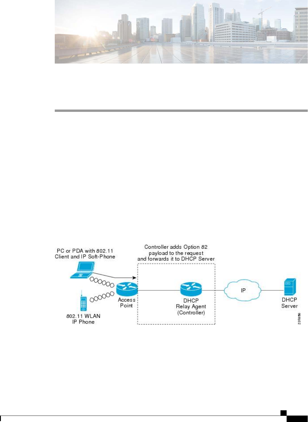
CHAPTER 52
Configuring DHCP Option 82
•Information About DHCP Option 82, page 421
•Restrictions for DHCP Option 82, page 422
•Configuring DHCP Option 82 (GUI), page 422
•Configuring DHCP Option 82 (CLI), page 422
Information About DHCP Option 82
DHCP option 82 provides additional security when DHCP is used to allocate network addresses. It enables
the controller to act as a DHCP relay agent to prevent DHCP client requests from untrusted sources. You can
configure the controller to add option 82 information to DHCP requests from clients before forwarding the
requests to the DHCP server.
Figure 43: DHCP Option 82
The access point forwards all DHCP requests from a client to the controller. The controller adds the DHCP
option 82 payload and forwards the request to the DHCP server. The payload can contain the MAC address
or the MAC address and SSID of the access point, depending on how you configure this option.
Cisco Wireless LAN Controller Configuration Guide, Release 7.4
OL-28744-01 421

Any DHCP packets that already include a relay agent option are dropped at the controller.Note
For DHCP option 82 to operate correctly, DHCP proxy must be enabled.
Restrictions for DHCP Option 82
•DHCP option 82 is not supported for use with auto-anchor mobility.
Configuring DHCP Option 82 (GUI)
Step 1 Choose Controller >Advanced >DHCP to open the DHCP Parameters page.
Step 2 Select the Enable DHCP Proxy check box to enable DHCP proxy.
Step 3 Choose a DHCP Option 82 Remote ID field format from the drop-down list to specify the format of the DHCP option
82 payload.
For more information about the options available, see the Controller Online Help.
Step 4 Enter the DHCP Timeout. The timeout value is globally applicable.
Step 5 Click Apply.
Step 6 Click Save Configuration .
What to Do Next
On the controller CLI, you can enable DHCP option 82 on the dynamic interface to which the WLAN is
associated by entering this command:
config interface dhcp dynamic-interface interface-name option-82 enable
Configuring DHCP Option 82 (CLI)
•Configure the format of the DHCP option 82 payload by entering one of these commands:
◦config dhcp opt-82 remote-id ap_mac—Adds the MAC address of the access point to the DHCP
option 82 payload.
◦config dhcp opt-82 remote-id ap_mac:ssid—Adds the MAC address and SSID of the access
point to the DHCP option 82 payload.
◦config dhcp opt-82 remote-id ap-ethmac—Adds the Ethernet MAC address of the access point
to the DHCP option 82 payload.
◦config dhcp opt-82 remote-id apname:ssid—Adds the AP name and SSID of the access point
to the DHCP option 82 payload.
Cisco Wireless LAN Controller Configuration Guide, Release 7.4
422 OL-28744-01
Restrictions for DHCP Option 82

◦config dhcp opt-82 remote-id ap-group-name—Adds the AP group name to the DHCP option
82 payload.
◦config dhcp opt-82 remote-id flex-group-name—Adds the FlexConnect group name to the DHCP
option 82 payload.
◦config dhcp opt-82 remote-id ap-location—Adds the AP location to the DHCP option 82 payload.
◦config dhcp opt-82 remote-id apmac-vlan-id—Adds the MAC address of the access point and
the VLAN ID to the DHCP option 82 payload.
◦config dhcp opt-82 remote-id apname-vlan-id—Adds the AP name and its VLAN ID to the
DHCP option 82 payload.
◦config dhcp opt-82 remote-id ap-ethmac-ssid—Adds the Ethernet MAC address of the access
point and the SSID to the DHCP option 82 payload.
•Enable DHCP Option 82 on the dynamic interface to which the WLAN is associated by entering this
command:
config interface dhcp dynamic-interface interface-name option-82 enable
•See the status of DHCP option 82 on the dynamic interface by entering the show interface detailed
dynamic-interface-namecommand.
Cisco Wireless LAN Controller Configuration Guide, Release 7.4
OL-28744-01 423
Configuring DHCP Option 82 (CLI)

Cisco Wireless LAN Controller Configuration Guide, Release 7.4
424 OL-28744-01
Configuring DHCP Option 82 (CLI)

CHAPTER 53
Configuring and Applying Access Control Lists
•Information About Access Control Lists, page 425
•Restrictions for Access Control Lists, page 425
•Configuring and Applying Access Control Lists (GUI), page 426
•Configuring and Applying Access Control Lists (CLI), page 430
Information About Access Control Lists
An Access Control List (ACL) is a set of rules used to limit access to a particular interface (for example, if
you want to restrict a wireless client from pinging the management interface of the controller). After ACLs
are configured on the controller, they can be applied to the management interface, the AP-manager interface,
any of the dynamic interfaces, or a WLAN to control data traffic to and from wireless clients or to the controller
central processing unit (CPU) to control all traffic destined for the CPU.
You may also want to create a preauthentication ACL for web authentication. Such an ACL could be used to
allow certain types of traffic before authentication is complete.
Both IPv4 and IPv6 ACL are supported. IPv6 ACLs support the same options as IPv4 ACLs including source,
destination, source and destination ports.
You can enable only IPv4 traffic in your network by blocking IPv6 traffic. That is, you can configure an
IPv6 ACL to deny all IPv6 traffic and apply it on specific or all WLANs.
Note
Restrictions for Access Control Lists
•You can define up to 64 ACLs, each with up to 64 rules (or filters) for both IPv4 and IPv6. Each rule
has parameters that affect its action. When a packet matches all of the parameters for a rule, the action
set for that rule is applied to the packet.
•When you apply CPU ACLs on a Cisco 5500 Series Controller or a Cisco WiSM2, you must permit
traffic towards the virtual interface IP address for web authentication.
Cisco Wireless LAN Controller Configuration Guide, Release 7.4
OL-28744-01 425

•All ACLs have an implicit “deny all rule”as the last rule. If a packet does not match any of the rules, it
is dropped by the controller.
•If you are using an external web server with a Cisco 5500 Series Controller or a controller network
module, you must configure a preauthentication ACL on the WLAN for the external web server.
•If you apply an ACL to an interface or a WLAN, wireless throughput is degraded when downloading
from a 1-GBps file server. To improve throughput, remove the ACL from the interface or WLAN, move
the ACL to a neighboring wired device with a policy rate-limiting restriction, or connect the file server
using 100 Mbps rather than 1 Gbps.
•Multicast traffic received from wired networks that is destined to wireless clients is not processed by
WLC ACLs. Multicast traffic initiated from wireless clients, destined to wired networks or other wireless
clients on the same controller, is processed by WLC ACLs.
•ACLs are configured on the controller directly or configured through templates. The ACL name must
be unique.
•You can configure ACL per client (AAA overridden ACL) or on either an interface or a WLAN. The
AAA overridden ACL has the highest priority. However, each interface, WLAN, or per client ACL
configuration that you apply can override one another.
•If peer-to-peer blocking is enabled, traffic is blocked between peers even if the ACL allows traffic
between them.
Configuring and Applying Access Control Lists (GUI)
Configuring Access Control Lists
Step 1 Choose Security >Access Control Lists >Access Control Lists to open the Access Control Lists page.
Step 2 If you want to see if packets are hitting any of the ACLs configured on your controller, select the Enable Counters
check box and click Apply. Otherwise, leave the check box unselected, which is the default value. This feature is useful
when troubleshooting your system.
If you want to clear the counters for an ACL, hover your cursor over the blue drop-down arrow for that ACL
and choose Clear Counters.
Note
Step 3 Add a new ACL by clicking New. The Access Control Lists > New page appears.
Step 4 In the Access Control List Name text box, enter a name for the new ACL. You can enter up to 32 alphanumeric characters.
Step 5 Choose the ACL type. There are two types of ACL supported, IPv4 and IPv6.
Step 6 Click Apply. When the Access Control Lists page reappears, click the name of the new ACL.
Step 7 When the Access Control Lists > Edit page appears, click Add New Rule. The Access Control Lists > Rules > New
page appears.
Step 8 Configure a rule for this ACL as follows:
a) The controller supports up to 64 rules for each ACL. These rules are listed in order from 1 to 64. In the Sequence
text box, enter a value (between 1 and 64) to determine the order of this rule in relation to any other rules defined for
this ACL.
Cisco Wireless LAN Controller Configuration Guide, Release 7.4
426 OL-28744-01
Configuring and Applying Access Control Lists (GUI)

If rules 1 through 4 are already defined and you add rule 29, it is added as rule 5. If you add or change a
sequence number for a rule, the sequence numbers for other rules adjust to maintain a continuous sequence.
For instance, if you change a rule’s sequence number from 7 to 5, the rules with sequence numbers 5 and 6
are automatically reassigned as 6 and 7, respectively.
Note
b) From the Source drop-down list, choose one of these options to specify the source of the packets to which this ACL
applies:
•Any—Any source (this is the default value).
•IP Address—A specific source. If you choose this option, enter the IP address and netmask of the source in
the text boxes. If you are configuring IPv6 ACL, enter the IPv6 address and prefix length of the destination in
the text boxes.
c) From the Destination drop-down list, choose one of these options to specify the destination of the packets to which
this ACL applies:
•Any—Any destination (this is the default value).
•IP Address—A specific destination. If you choose this option, enter the IP address and netmask of the destination
in the text boxes. If you are configuring IPv6 ACL, enter the IPv6 address and prefix length of the destination
in the text boxes.
d) From the Protocol drop-down list, choose the protocol ID of the IP packets to be used for this ACL. These are the
protocol options:
•Any—Any protocol (this is the default value)
•TCP—Transmission Control Protocol
•UDP—User Datagram Protocol
•ICMP/ICMPv6—Internet Control Message Protocol
ICMPv6 is only available for IPv6
ACL.
Note
•ESP—IP Encapsulating Security Payload
•AH—Authentication Header
•GRE—Generic Routing Encapsulation
•IP in IP—Internet Protocol (IP) in IP (permits or denies IP-in-IP packets)
•Eth Over IP—Ethernet-over-Internet Protocol
•OSPF—Open Shortest Path First
•Other—Any other Internet Assigned Numbers Authority (IANA) protocol
If you choose Other, enter the number of the desired protocol in the Protocol text box. You can find
the list of available protocols in the INAI website.
Note
The controller can permit or deny only IP packets in an ACL. Other types of packets (such as ARP packets) cannot
be specified.
e) If you chose TCP or UDP in the previous step, two additional parameters appear: Source Port and Destination Port.
These parameters enable you to choose a specific source port and destination port or port ranges. The port options
Cisco Wireless LAN Controller Configuration Guide, Release 7.4
OL-28744-01 427
Configuring and Applying Access Control Lists (GUI)

are used by applications that send and receive data to and from the networking stack. Some ports are designated for
certain applications such as Telnet, SSH, HTTP, and so on.
Source and Destination ports based on the ACL
type.
Note
f) From the DSCP drop-down list, choose one of these options to specify the differentiated services code point (DSCP)
value of this ACL. DSCP is an IP header text box that can be used to define the quality of service across the Internet.
•Any—Any DSCP (this is the default value)
•Specific—A specific DSCP from 0 to 63, which you enter in the DSCP edit box
g) From the Direction drop-down list, choose one of these options to specify the direction of the traffic to which this
ACL applies:
•Any—Any direction (this is the default value)
•Inbound—From the client
•Outbound—To the client
If you are planning to apply this ACL to the controller CPU, the packet direction does not have any
significance, it is always ‘Any’.
Note
h) From the Action drop-down list, choose Deny to cause this ACL to block packets or Permit to cause this ACL to
allow packets. The default value is Deny.
i) Click Apply to commit your changes. The Access Control Lists > Edit page reappears, showing the rules for this
ACL.
The Deny Counters fields shows the number of times that packets have matched the explicit deny ACL rule. The
Number of Hits field shows the number of times that packets have matched an ACL rule. You must enable ACL
counters on the Access Control Lists page to enable these fields.
If you want to edit a rule, click the sequence number of the desired rule to open the Access Control Lists >
Rules > Edit page. If you want to delete a rule, hover your cursor over the blue drop-down arrow for the
desired rule and choose Remove.
Note
j) Repeat this procedure to add any additional rules for this ACL.
Step 9 Click Save Configuration to save your changes.
Step 10 Repeat this procedure to add any additional ACLs.
Applying an Access Control List to an Interface
Step 1 Choose Controller >Interfaces.
Step 2 Click the name of the desired interface. The Interfaces > Edit page for that interface appears.
Step 3 Choose the desired ACL from the ACL Name drop-down list and click Apply. The default is None.
Only IPv4 ACL are supported as interface
ACL.
Note
Step 4 Click Save Configuration to save your changes.
Cisco Wireless LAN Controller Configuration Guide, Release 7.4
428 OL-28744-01
Configuring and Applying Access Control Lists (GUI)

Applying an Access Control List to the Controller CPU
Step 1 Choose Security >Access Control Lists >CPU Access Control Lists to open the CPU Access Control Lists page.
Step 2 Select the Enable CPU ACL check box to enable a designated ACL to control the traffic to the controller CPU or
unselect the check box to disable the CPU ACL feature and remove any ACL that had been applied to the CPU. The
default value is unselected.
Step 3 From the ACL Name drop-down list, choose the ACL that will control the traffic to the controller CPU. None is the
default value when the CPU ACL feature is disabled. If you choose None while the CPU ACL Enable check box is
selected, an error message appears indicating that you must choose an ACL.
This parameter is available only if you have selected the CPU ACL Enable check
box.
Note
When CPU ACL is enabled, it is applicable to both wireless and wired traffic. Only IPv4 ACL are supported
as CPU ACL.
Note
Step 4 Click Apply to commit your changes.
Step 5 Click Save Configuration to save your changes.
Applying an Access Control List to a WLAN
Step 1 Choose WLANs to open the WLANs page.
Step 2 Click the ID number of the desired WLAN to open the WLANs > Edit page.
Step 3 Choose the Advanced tab to open the WLANs > Edit (Advanced) page.
Step 4 From the Override Interface ACL drop-down list, choose the IPv4 or IPv6 ACL that you want to apply to this WLAN.
The ACL that you choose overrides any ACL that is configured for the interface. None is the default value.
To support centralized access control through AAA server such as ISE or ACS, IPv6 ACL must be configured
on the controller and the WLAN must be configured with AAA override enabled feature.
Note
Step 5 Click Apply.
Step 6 Click Save Configuration.
Cisco Wireless LAN Controller Configuration Guide, Release 7.4
OL-28744-01 429
Configuring and Applying Access Control Lists (GUI)

Applying a Preauthentication Access Control List to a WLAN
Step 1 Choose WLANs to open the WLANs page.
Step 2 Click the ID number of the desired WLAN to open the WLANs > Edit page.
Step 3 Choose the Security and Layer 3 tabs to open the WLANs > Edit (Security > Layer 3) page.
Step 4 Select the Web Policy check box.
Step 5 From the Preauthentication ACL drop-down list, choose the desired ACL and click Apply. None is the default value.
Step 6 Click Save Configuration to save your changes.
Configuring and Applying Access Control Lists (CLI)
Configuring Access Control Lists
Step 1 See all of the ACLs that are configured on the controller by entering this command:
show [ipv6]acl summary
Step 2 See detailed information for a particular ACL by entering this command:
show [ipv6]acl detailed acl_name
The Counter text box increments each time a packet matches an ACL rule, and the DenyCounter text box increments
each time a packet does not match any of the rules.
If a traffic/request is allowed from the controller by a permit rule, then the response to the traffic/request in the
opposite direction also is allowed and cannot be blocked by a deny rule in the ACL.
Note
Step 3 Enable or disable ACL counters for your controller by entering this command:
config acl counter {start |stop}
If you want to clear the current counters for an ACL, enter the clear acl counters acl_name command.
Note
Step 4 Add a new ACL by entering this command:
config [ipv6] acl create acl_name.
You can enter up to 32 alphanumeric characters for the acl_name parameter.
When you try to create an interface name with space, the controller CLI does not create an interface. For example,
if you want to create an interface name int 3, the CLI will not create this since there is a space between int and
3. If you want to use int 3 as the interface name, you need to enclose within single quotes like ‘int 3’.
Note
Step 5 Add a rule for an ACL by entering this command:
config [ipv6] acl rule add acl_name rule_index
Step 6 Configure an ACL rule by entering config [ipv6] acl rule command:
Step 7 Save your settings by entering this command:
save config
Cisco Wireless LAN Controller Configuration Guide, Release 7.4
430 OL-28744-01
Configuring and Applying Access Control Lists (CLI)

To delete an ACL, enter the config [ipv6]acl delete acl_name command. To delete an ACL rule, enter the
config [ipv6]acl rule delete acl_name rule_index command.
Note
Applying Access Control Lists
Step 1 Perform any of the following:
•To apply an ACL to the data path, enter this command:
config acl apply acl_name
•To apply an ACL to the controller CPU to restrict the type of traffic (wired, wireless, or both) reaching the CPU,
enter this command:
config acl cpu acl_name {wired | wireless | both}
To see the ACL that is applied to the controller CPU, enter the show acl cpu command. To remove the
ACL that is applied to the controller CPU, enter the config acl cpu none command.
Note
For 2504 and 4400 series WLC, the CPU ACL cannot be used to control the CAPWAP traffic. Use the
access-list on the network to control CAPWAP traffic.
Note
•To apply an ACL to a WLAN, enter this command:
config wlan acl wlan_id acl_name
To see the ACL that is applied to a WLAN, enter the show wlan wlan_id command. To remove the ACL
that is applied to a WLAN, enter the config wlan acl wlan_id none command.
Note
•To apply a preauthentication ACL to a WLAN, enter this command:
config wlan security web-auth acl wlan_id acl_name
Step 2 Save your changes by entering this command:
save config
Cisco Wireless LAN Controller Configuration Guide, Release 7.4
OL-28744-01 431
Configuring and Applying Access Control Lists (CLI)

Cisco Wireless LAN Controller Configuration Guide, Release 7.4
432 OL-28744-01
Configuring and Applying Access Control Lists (CLI)

CHAPTER 54
Configuring Management Frame Protection
•Information About Management Frame Protection, page 433
•Restrictions for Management Frame Protection, page 435
•Configuring Management Frame Protection (GUI), page 435
•Viewing the Management Frame Protection Settings (GUI), page 435
•Configuring Management Frame Protection (CLI), page 436
•Viewing the Management Frame Protection Settings (CLI), page 436
•Debugging Management Frame Protection Issues (CLI), page 436
Information About Management Frame Protection
Management frame protection (MFP) provides security for the otherwise unprotected and unencrypted 802.11
management messages passed between access points and clients. MFP provides both infrastructure and client
support.
•Infrastructure MFP—Protects management frames by detecting adversaries that are invoking
denial-of-service attacks, flooding the network with associations and probes, interjecting as rogue access
points, and affecting network performance by attacking the QoS and radio measurement frames.
Infrastructure MFP is a global setting that provides a quick and effective means to detect and report
phishing incidents.
Specifically, infrastructure MFP protects 802.11 session management functions by adding message
integrity check information elements (MIC IEs) to the management frames emitted by access points
(and not those emitted by clients), which are then validated by other access points in the network.
Infrastructure MFP is passive. It can detect and report intrusions but has no means to stop them.
•Client MFP—Shields authenticated clients from spoofed frames, preventing many of the common attacks
against wireless LANs from becoming effective. Most attacks, such as deauthentication attacks, revert
to simply degrading performance by contending with valid clients.
Specifically, client MFP encrypts management frames are sent between access points and CCXv5 clients
so that both the access points and clients can take preventative action by dropping spoofed class 3
management frames (that is, management frames passed between an access point and a client that is
authenticated and associated). Client MFP leverages the security mechanisms defined by IEEE 802.11i
Cisco Wireless LAN Controller Configuration Guide, Release 7.4
OL-28744-01 433

to protect the following types of class 3 unicast management frames: disassociation, deauthentication,
and QoS (WMM) action. Client MFP protects a client-access point session from the most common type
of denial-of-service attack. It protects class 3 management frames by using the same encryption method
used for the session’s data frames. If a frame received by the access point or client fails decryption, it is
dropped, and the event is reported to the controller.
To use client MFP, clients must support CCXv5 MFP and must negotiate WPA2 using either TKIP or
AES-CCMP. EAP or PSK may be used to obtain the PMK. CCKM and controller mobility management
are used to distribute session keys between access points for Layer 2 and Layer 3 fast roaming.
To prevent attacks using broadcast frames, access points supporting CCXv5 will not
emit any broadcast class 3 management frames (such as disassociation, deauthentication,
or action). CCXv5 clients and access points must discard broadcast class 3 management
frames.
Client MFP supplements infrastructure MFP rather than replaces it because infrastructure
MFP continues to detect and report invalid unicast frames sent to clients that are not
client-MFP capable as well as invalid class 1 and 2 management frames. Infrastructure
MFP is applied only to management frames that are not protected by client MFP.
Infrastructure MFP consists of three main components:
Note
•Management frame protection—The access point protects the management frames it transmits by adding
a MIC IE to each frame. Any attempt to copy, alter, or replay the frame invalidates the MIC, causing
any receiving access point configured to detect MFP frames to report the discrepancy. MFP is supported
for use with Cisco Aironet lightweight access points.
•Management frame validation—In infrastructure MFP, the access point validates every management
frame that it receives from other access points in the network. It ensures that the MIC IE is present (when
the originator is configured to transmit MFP frames) and matches the content of the management frame.
If it receives any frame that does not contain a valid MIC IE from a BSSID belonging to an access point
that is configured to transmit MFP frames, it reports the discrepancy to the network management system.
In order for the timestamps to operate properly, all controllers must be Network Time Protocol (NTP)
synchronized.
•Event reporting—The access point notifies the controller when it detects an anomaly, and the controller
aggregates the received anomaly events and can report the results through SNMP traps to the network
management system.
Client MFP uses the same event reporting mechanisms as infrastructure MFP.Note
Infrastructure MFP is enabled by default and can be disabled globally. When you upgrade from a previous
software release, infrastructure MFP is disabled globally if access point authentication is enabled because the
two features are mutually exclusive. Once infrastructure MFP is enabled globally, signature generation (adding
MICs to outbound frames) can be disabled for selected WLANs, and validation can be disabled for selected
access points.
Client MFP is enabled by default on WLANs that are configured for WPA2. It can be disabled, or it can be
made mandatory (in which case, only clients that negotiate MFP are allowed to associate) on selected WLANs.
Cisco Wireless LAN Controller Configuration Guide, Release 7.4
434 OL-28744-01
Information About Management Frame Protection

Restrictions for Management Frame Protection
•Lightweight access points support infrastructure MFP in local and monitor modes and in FlexConnect
mode when the access point is connected to a controller. They support client MFP in local, FlexConnect,
and bridge modes.
•OEAP 600 Series Access points do not support MFP.
•Client MFP is supported for use only with CCXv5 clients using WPA2 with TKIP or AES-CCMP.
•Non-CCXv5 clients may associate to a WLAN if client MFP is disabled or optional.
•Error reports generated on a FlexConnect access point in standalone mode cannot be forwarded to the
controller and are dropped.
Configuring Management Frame Protection (GUI)
Step 1 Choose Security> Wireless Protection Policies > AP Authentication/MFP to open the AP Authentication Policy page.
Step 2 Enable infrastructure MFP globally for the controller by choosing Management Frame Protection from the Protection
Type drop-down list.
Step 3 Click Apply to commit your changes.
If more than one controller is included in the mobility group, you must configure a Network Time Protocol
(NTP) server on all controllers in the mobility group that are configured for infrastructure MFP.
Note
Step 4 Configure client MFP for a particular WLAN after infrastructure MFP has been enabled globally for the controller as
follows:
a) Choose WLANs.
b) Click the profile name of the desired WLAN. The WLANs > Edit page appears.
c) Choose Advanced. The WLANs > Edit (Advanced) page appears.
d) Choose Disabled,Optional, or Required from the MFP Client Protection drop-down list. The default value is
Optional. If you choose Required, clients are allowed to associate only if MFP is negotiated (that is, if WPA2 is
configured on the controller and the client supports CCXv5 MFP and is also configured for WPA2).
For Cisco OEAP 600, MFP is not supported. It should either be Disabled or Optional.Note
e) Click Apply to commit your changes.
Step 5 Click Save Configuration to save your settings.
Viewing the Management Frame Protection Settings (GUI)
To see the controller’s current global MFP settings, choose Security >Wireless Protection Policies >
Management Frame Protection. The Management Frame Protection Settings page appears.
On this page, you can see the following MFP settings:
Cisco Wireless LAN Controller Configuration Guide, Release 7.4
OL-28744-01 435
Restrictions for Management Frame Protection

•The Management Frame Protection field shows if infrastructure MFP is enabled globally for the
controller.
•The Controller Time Source Valid field indicates whether the controller time is set locally (by manually
entering the time) or through an external source (such as the NTP server). If the time is set by an external
source, the value of this field is “True.”If the time is set locally, the value is “False.”The time source is
used for validating the timestamp on management frames between access points of different controllers
within a mobility group.
•The Client Protection field shows if client MFP is enabled for individual WLANs and whether it is
optional or required.
Configuring Management Frame Protection (CLI)
•Enable or disable infrastructure MFP globally for the controller by entering this command:
config wps mfp infrastructure {enable |disable}
•Enable or disable client MFP on a specific WLAN by entering this command:
config wlan mfp client {enable |disable}wlan_id [required ]
If you enable client MFP and use the optional required parameter, clients are allowed to associate only
if MFP is negotiated.
Viewing the Management Frame Protection Settings (CLI)
•See the controller’s current MFP settings by entering this command:
show wps mfp summary
•See the current MFP configuration for a particular WLAN by entering this command:
show wlan wlan_id
•See whether client MFP is enabled for a specific client by entering this command:
show client detail client_mac
•See MFP statistics for the controller by entering this command:
show wps mfp statistics
This report contains no data unless an active attack is in progress. Examples of various error types are
shown for illustration only. This table is cleared every 5 minutes when the data is forwarded to any network
management stations.
Note
Debugging Management Frame Protection Issues (CLI)
•Use this command if you experience any problems with MFP:
debug wps mfp ? {enable |disable}
where ? is one of the following:
client—Configures debugging for client MFP messages.
Cisco Wireless LAN Controller Configuration Guide, Release 7.4
436 OL-28744-01
Configuring Management Frame Protection (CLI)

capwap—Configures debugging for MFP messages between the controller and access points.
detail—Configures detailed debugging for MFP messages.
report—Configures debugging for MFP reporting.
mm—Configures debugging for MFP mobility (inter-controller) messages.
Cisco Wireless LAN Controller Configuration Guide, Release 7.4
OL-28744-01 437
Debugging Management Frame Protection Issues (CLI)

Cisco Wireless LAN Controller Configuration Guide, Release 7.4
438 OL-28744-01
Debugging Management Frame Protection Issues (CLI)

CHAPTER 55
Configuring Client Exclusion Policies
•Configuring Client Exclusion Policies (GUI), page 439
•Configuring Client Exclusion Policies (CLI), page 440
Configuring Client Exclusion Policies (GUI)
Step 1 Choose Security >Wireless Protection Policies >Client Exclusion Policies to open the Client Exclusion Policies
page.
Step 2 Select any of these check boxes if you want the controller to exclude clients for the condition specified. The default value
for each exclusion policy is enabled.
•Excessive 802.11 Association Failures—Clients are excluded on the sixth 802.11 association attempt, after five
consecutive failures.
•Excessive 802.11 Authentication Failures—Clients are excluded on the sixth 802.11 authentication attempt, after
five consecutive failures.
•Excessive 802.1X Authentication Failures—Clients are excluded on the fourth 802.1X authentication attempt,
after three consecutive failures.
•IP Theft or IP Reuse—Clients are excluded if the IP address is already assigned to another device.
•Excessive Web Authentication Failures—Clients are excluded on the fourth web authentication attempt, after
three consecutive failures.
Step 3 Click Apply.
Step 4 Click Save Configuration.
Cisco Wireless LAN Controller Configuration Guide, Release 7.4
OL-28744-01 439

Configuring Client Exclusion Policies (CLI)
Step 1 Enable or disable the controller to exclude clients on the sixth 802.11 association attempt, after five consecutive failures
by entering this command:
config wps client-exclusion 802.11-assoc {enable |disable}
Step 2 Enable or disable the controller to exclude clients on the sixth 802.11 authentication attempt, after five consecutive
failures by entering this command:
config wps client-exclusion 802.11-auth {enable |disable}
Step 3 Enable or disable the controller to exclude clients on the fourth 802.1X authentication attempt, after three consecutive
failures by entering this command:
config wps client-exclusion 802.1x-auth {enable |disable}
Step 4 Enable or disable the controller to exclude clients if the IP address is already assigned to another device by entering this
command:
config wps client-exclusion ip-theft {enable |disable}
Step 5 Enable or disable the controller to exclude clients on the fourth web authentication attempt, after three consecutive
failures by entering this command:
config wps client-exclusion web-auth {enable |disable}
Step 6 Enable or disable the controller to exclude clients for all of the above reasons by entering this command:
config wps client-exclusion all {enable |disable}
Step 7 Use the following command to add or delete client exclusion entries.
config exclusionlist {add MAC [description] | delete MAC | description MAC [description]}
Step 8 Save your changes by entering this command:
save config
Step 9 See a list of clients that have been dynamically excluded, by entering this command:
show exclusionlist
Information similar to the following appears:
Dynamically Disabled Clients
----------------------------
MAC Address Exclusion Reason Time Remaining (in secs)
----------- ---------------- ------------------------
00:40:96:b4:82:55 802.1X Failure 51
Step 10 See the client exclusion policy configuration settings by entering this command:
show wps summary
Information similar to the following appears:
Auto-Immune
Auto-Immune.................................... Disabled
Client Exclusion Policy
Excessive 802.11-association failures.......... Enabled
Excessive 802.11-authentication failures....... Enabled
Cisco Wireless LAN Controller Configuration Guide, Release 7.4
440 OL-28744-01
Configuring Client Exclusion Policies (CLI)

Excessive 802.1x-authentication................ Enabled
IP-theft....................................... Enabled
Excessive Web authentication failure........... Enabled
Signature Policy
Signature Processing........................ Enabled
Cisco Wireless LAN Controller Configuration Guide, Release 7.4
OL-28744-01 441
Configuring Client Exclusion Policies (CLI)

Cisco Wireless LAN Controller Configuration Guide, Release 7.4
442 OL-28744-01
Configuring Client Exclusion Policies (CLI)

CHAPTER 56
Configuring Identity Networking
•Information About Identity Networking, page 443
•RADIUS Attributes Used in Identity Networking, page 444
Information About Identity Networking
In most wireless LAN systems, each WLAN has a static policy that applies to all clients associated with an
SSID. Although powerful, this method has limitations because it requires clients to associate with different
SSIDs to inherit different QoS and security policies.
However, the Cisco Wireless LAN solution supports identity networking, which allows the network to advertise
a single SSID but allows specific users to inherit different QoS or security policies based on their user profiles.
The specific policies that you can control using identity networking are as follows:
•ACL—When the ACL attribute is present in the RADIUS Access Accept, the system applies the ACL
name to the client station after it authenticates, which overrides any ACLs that are assigned to the
interface.
•VLAN—When a VLAN Interface-name or VLAN tag is present in a RADIUS Access Accept, the
system places the client on a specific interface.
The VLAN feature only supports MAC filtering, 802.1X, and WPA. The VLAN feature
does not support web authentication or IPsec.
Note
•Tunnel Attributes.
When any of the other RADIUS attributes (QoS-Level, ACL-Name, Interface-Name,
or VLAN-Tag), which are described later in this section, are returned, the Tunnel
Attributes must also be returned.
Note
Cisco Wireless LAN Controller Configuration Guide, Release 7.4
OL-28744-01 443

The operating system’s local MAC filter database has been extended to include the interface name, allowing
local MAC filters to specify to which interface the client should be assigned. A separate RADIUS server can
also be used, but the RADIUS server must be defined using the Security menus.
RADIUS Attributes Used in Identity Networking
QoS-Level
This section explains the RADIUS attributes used in identity networking.
This attribute indicates the QoS level to be applied to the mobile client's traffic within the switching fabric,
as well as over the air. This example shows a summary of the QoS-Level Attribute format. The text boxes
are transmitted from left to right.
0123
01234567890123456789012345678901
+-+-+-+-+-+-+-+-+-+-+-+-+-+-+-+-+-+-+-+-+-+-+-+-+-+-+-+-+-+-+-+-+
| Type | Length | Vendor-Id
+-+-+-+-+-+-+-+-+-+-+-+-+-+-+-+-+-+-+-+-+-+-+-+-+-+-+-+-+-+-+-+-+
Vendor-Id (cont.) | Vendor type | Vendor length |
+-+-+-+-+-+-+-+-+-+-+-+-+-+-+-+-+-+-+-+-+-+-+-+-+-+-+-+-+-+-+-+-+
| QoS Level |
+-+-+-+-+-+-+-+-+-+-+-+-+-+-+-+-+-+-+-+-+-+-+-+-+-+-+-+-+-+-+-+-+
•Type –26 for Vendor-Specific
•Length –10
•Vendor-Id –14179
•Vendor type –2
•Vendor length –4
•Value –Three octets:
◦3–Bronze (Background)
◦0–Silver (Best Effort)
◦1–Gold (Video)
◦2–Platinum (Voice)
ACL-Name
This attribute indicates the ACL name to be applied to the client. A summary of the ACL-Name Attribute
format is shown below. The text boxes are transmitted from left to right.
0123
01234567890123456789012345678901
+-+-+-+-+-+-+-+-+-+-+-+-+-+-+-+-+-+-+-+-+-+-+-+-+-+-+-+-+-+-+-+-+
| Type | Length | Vendor-Id
+-+-+-+-+-+-+-+-+-+-+-+-+-+-+-+-+-+-+-+-+-+-+-+-+-+-+-+-+-+-+-+-+
Vendor-Id (cont.) | Vendor type | Vendor length |
+-+-+-+-+-+-+-+-+-+-+-+-+-+-+-+-+-+-+-+-+-+-+-+-+-+-+-+-+-+-+-+-+
| ACL Name...
+-+-+-+-+-+-+-+-+-+-+-+-+-+-+-
Cisco Wireless LAN Controller Configuration Guide, Release 7.4
444 OL-28744-01
RADIUS Attributes Used in Identity Networking

•Type –26 for Vendor-Specific
•Length –>7
•Vendor-Id –14179
•Vendor type –6
•Vendor length –>0
•Value –A string that includes the name of the ACL to use for the client
Interface Name
This attribute indicates the VLAN Interface a client is to be associated to. A summary of the Interface-Name
Attribute format is shown below. The text boxes are transmitted from left to right.
0123
01234567890123456789012345678901
+-+-+-+-+-+-+-+-+-+-+-+-+-+-+-+-+-+-+-+-+-+-+-+-+-+-+-+-+-+-+-+-+
| Type | Length | Vendor-Id
+-+-+-+-+-+-+-+-+-+-+-+-+-+-+-+-+-+-+-+-+-+-+-+-+-+-+-+-+-+-+-+-+
Vendor-Id (cont.) | Vendor type | Vendor length |
+-+-+-+-+-+-+-+-+-+-+-+-+-+-+-+-+-+-+-+-+-+-+-+-+-+-+-+-+-+-+-+-+
| Interface Name...
+-+-+-+-+-+-+-+-+-+-+-+-+-+-+-
•Type –26 for Vendor-Specific
•Length –>7
•Vendor-Id –14179
•Vendor type –5
•Vendor length –>0
•Value –A string that includes the name of the interface the client is to be assigned to.
This Attribute only works when MAC filtering is enabled or if 802.1X or WPA is used
as the security policy.
Note
VLAN Tag
This attribute indicates the group ID for a particular tunneled session and is also known as the
Tunnel-Private-Group-ID attribute.
This attribute might be included in the Access-Request packet if the tunnel initiator can predetermine the
group resulting from a particular connection and should be included in the Access-Accept packet if this tunnel
session is to be treated as belonging to a particular private group. Private groups may be used to associate a
tunneled session with a particular group of users. For example, it may be used to facilitate routing of unregistered
IP addresses through a particular interface. It should be included in Accounting-Request packets which contain
Acct-Status-Type attributes with values of either Start or Stop and which pertain to a tunneled session.
Cisco Wireless LAN Controller Configuration Guide, Release 7.4
OL-28744-01 445
RADIUS Attributes Used in Identity Networking

A summary of the Tunnel-Private-Group-ID Attribute format is shown below. The text boxes are transmitted
from left to right.
0123
01234567890123456789012345678901
+-+-+-+-+-+-+-+-+-+-+-+-+-+-+-+-+-+-+-+-+-+-+-+-+-+-+-+-+-+-+-+-+
| Type | Length | Tag | String...
+-+-+-+-+-+-+-+-+-+-+-+-+-+-+-+-+-+-+-+-+-+-+-+-+-+-+-+-+-+-+-+-+
•Type –81 for Tunnel-Private-Group-ID.
•Length –>= 3
•Tag –The Tag text box is one octet in length and is intended to provide a means of grouping attributes
in the same packet which refer to the same tunnel. If the value of the Tag text box is greater than 0x00
and less than or equal to 0x1F, it should be interpreted as indicating which tunnel (of several alternatives)
this attribute pertains. If the Tag text box is greater than 0x1F, it should be interpreted as the first byte
of the following String text box.
•String –This text box must be present. The group is represented by the String text box. There is no
restriction on the format of group IDs.
When any of the other RADIUS attributes (QoS-Level, ACL-Name, Interface-Name,
or VLAN-Tag) are returned, the Tunnel Attributes must also be returned.
Note
Tunnel Attributes
RFC 2868 defines RADIUS tunnel attributes used for authentication and authorization, and RFC2867 defines
tunnel attributes used for accounting. Where the IEEE 802.1X authenticator supports tunneling, a compulsory
tunnel may be set up for the Supplicant as a result of the authentication.
In particular, it may be desirable to allow a port to be placed into a particular VLAN, defined in IEEE 8021Q,
based on the result of the authentication. This configuration can be used, for example, to allow a wireless host
to remain on the same VLAN as it moves within a campus network.
The RADIUS server typically indicates the desired VLAN by including tunnel attributes within the
Access-Accept. However, the IEEE 802.1X authenticator may also provide a hint as to the VLAN to be
assigned to the Supplicant by including Tunnel attributes within the AccessRequest.
For use in VLAN assignment, the following tunnel attributes are used:
•Tunnel-Type=VLAN (13)
•Tunnel-Medium-Type=802
•Tunnel-Private-Group-ID=VLANID
The VLAN ID is 12 bits, with a value between 1 and 4094, inclusive. Because the Tunnel-Private-Group-ID
is of type String as defined in RFC 2868, for use with IEEE 802.1X, the VLANID integer value is encoded
as a string.
When Tunnel attributes are sent, it is necessary to fill in the Tag text box. As noted in RFC 2868, section 3.1:
•The Tag text box is one octet in length and is intended to provide a means of grouping attributes in the
same packet that refer to the same tunnel. Valid values for this text box are 0x01 through 0x1F, inclusive.
If the Tag text box is unused, it must be zero (0x00).
Cisco Wireless LAN Controller Configuration Guide, Release 7.4
446 OL-28744-01
RADIUS Attributes Used in Identity Networking

•For use with Tunnel-Client-Endpoint, Tunnel-Server-Endpoint, Tunnel-Private-Group-ID,
Tunnel-Assignment-ID, Tunnel-Client-Auth-ID or Tunnel-Server-Auth-ID attributes (but not
Tunnel-Type, Tunnel-Medium-Type, Tunnel-Password, or Tunnel-Preference), a tag text box of greater
than 0x1F is interpreted as the first octet of the following text box.
•Unless alternative tunnel types are provided, (e.g. for IEEE 802.1X authenticators that may support
tunneling but not VLANs), it is only necessary for tunnel attributes to specify a single tunnel. As a result,
where it is only desired to specify the VLANID, the tag text box should be set to zero (0x00) in all tunnel
attributes. Where alternative tunnel types are to be provided, tag values between 0x01 and 0x1F should
be chosen.
Cisco Wireless LAN Controller Configuration Guide, Release 7.4
OL-28744-01 447
RADIUS Attributes Used in Identity Networking

Cisco Wireless LAN Controller Configuration Guide, Release 7.4
448 OL-28744-01
RADIUS Attributes Used in Identity Networking

CHAPTER 57
Configuring AAA Override
•Information About AAA Override, page 449
•Restrictions for AAA Override, page 449
•Updating the RADIUS Server Dictionary File for Proper QoS Values, page 450
•Configuring AAA Override (GUI), page 451
•Configuring AAA Override (CLI), page 451
Information About AAA Override
The AAA Override option of a WLAN enables you to configure the WLAN for identity networking. It enables
you to apply VLAN tagging, Quality of Service (QoS), and Access Control Lists (ACLs) to individual clients
based on the returned RADIUS attributes from the AAA server.
AAA Override for IPv6 ACLs
In order to support centralized access control through a centralized AAA server such as the Cisco Identity
Services Engine (ISE) or ACS, the IPv6 ACL can be provisioned on a per-client basis using AAA Override
attributes. In order to use this feature, the IPv6 ACL must be configured on the controller and the WLAN
must be configured with the AAA Override feature enabled. The actual named AAA attribute for an IPv6
ACL is Airespace-IPv6-ACL-Name, which is similar to the Airespace-ACL-Name attribute that is used for
provisioning an IPv4-based ACL. The AAA attribute returned contents should be a string equal to the name
of the IPv6 ACL as configured on the controller.
Restrictions for AAA Override
•If a client moves to a new interface due to the AAA override and then you apply an ACL to that interface,
the ACL does not take effect until the client reauthenticates. To work around this issue, apply the ACL
and then enable the WLAN so that all clients connect to the ACL that is already configured on the
interface, or disable and then reenable the WLAN after you apply the interface so that the clients can
reauthenticate.
•If the ACL returned from the AAA server does not exist on the controller or if the ACL is configured
with an incorrect name, then the clients are not allowed to be authenticated.
Cisco Wireless LAN Controller Configuration Guide, Release 7.4
OL-28744-01 449

•With FlexConnect local switching, Multicast is forwarded only for the VLAN that the SSID is mapped
to and not to any overridden VLANs.
•When the interface group is mapped to a WLAN and clients connect to the WLAN, the client does not
get the IP address in a round robin fashion. The AAA override with interface group is supported.
•Most of the configuration for allowing AAA override is done at the RADIUS server, where you should
configure the Access Control Server (ACS) with the override properties you would like it to return to
the controller (for example, Interface-Name, QoS-Level, and VLAN-Tag).
•On the controller, enable the Allow AAA Override configuration parameter using the GUI or CLI.
Enabling this parameter allows the controller to accept the attributes returned by the RADIUS server.
The controller then applies these attributes to its clients.
Updating the RADIUS Server Dictionary File for Proper QoS Values
If you are using a Steel-Belted RADIUS (SBR), FreeRadius, or similar RADIUS server, clients may not obtain
the correct QoS values after the AAA override feature is enabled. For these servers, which allow you to edit
the dictionary file, you need to update the file to reflect the proper QoS values: Silver is 0, Gold is 1, Platinum
is 2, and Bronze is 3. To update the RADIUS server dictionary file, follow these steps:
This issue does not apply to the Cisco Secure Access Control Server (ACS).Note
To update the RADIUS server dictionary file, follow these steps:
1Stop the SBR service (or other RADIUS service).
2Save the following text to the Radius_Install_Directory\Service folder as ciscowlan.dct:
################################################################################
# CiscoWLAN.dct- Cisco Wireless Lan Controllers
#
# (See README.DCT for more details on the format of this file)
################################################################################
# Dictionary - Cisco WLAN Controllers
#
# Start with the standard Radius specification attributes
#
@radius.dct
#
# Standard attributes supported by Airespace
#
# Define additional vendor specific attributes (VSAs)
#
MACRO Airespace-VSA(t,s) 26 [vid=14179 type1=%t% len1=+2 data=%s%]
ATTRIBUTE WLAN-Id Airespace-VSA(1, integer) cr
ATTRIBUTE Aire-QoS-Level Airespace-VSA(2, integer) r
VALUE Aire-QoS-Level Bronze 3
VALUE Aire-QoS-Level Silver 0
VALUE Aire-QoS-Level Gold 1
VALUE Aire-QoS-Level Platinum 2
ATTRIBUTE DSCP Airespace-VSA(3, integer) r
ATTRIBUTE 802.1P-Tag Airespace-VSA(4, integer) r
ATTRIBUTE Interface-Name Airespace-VSA(5, string) r
ATTRIBUTE ACL-Name Airespace-VSA(6, string) r
Cisco Wireless LAN Controller Configuration Guide, Release 7.4
450 OL-28744-01
Updating the RADIUS Server Dictionary File for Proper QoS Values

# This should be last.
################################################################################
# CiscoWLAN.dct - Cisco WLC dictionary
##############################################################################
3Open the dictiona.dcm file (in the same directory) and add the line “@ciscowlan.dct.”
4Save and close the dictiona.dcm file.
5Open the vendor.ini file (in the same directory) and add the following text:
vendor-product = Cisco WLAN Controller
dictionary = ciscowlan
ignore-ports = no
port-number-usage = per-port-type
help-id =
6Save and close the vendor.ini file.
7Start the SBR service (or other RADIUS service).
8Launch the SBR Administrator (or other RADIUS Administrator).
9Add a RADIUS client (if not already added). Choose Cisco WLAN Controller from the Make/Model
drop-down list.
Configuring AAA Override (GUI)
Step 1 Choose WLANs to open the WLANs page.
Step 2 Click the ID number of the WLAN that you want to configure. The WLANs > Edit page appears.
Step 3 Choose the Advanced tab.
Step 4 Select the Allow AAA Override check box to enable AAA override or unselect it to disable this feature. The default
value is disabled.
Step 5 Click Apply.
Step 6 Click Save Configuration.
Configuring AAA Override (CLI)
•Configure override of user policy through AAA on a WLAN by entering this command:
config wlan aaa-override {enable |disable}wlan-id
For wlan-id, enter a value between 1 and 16.
•Configure debugging of 802.1X AAA interactions by entering this command:
debug dot1x aaa {enable |disable}
Cisco Wireless LAN Controller Configuration Guide, Release 7.4
OL-28744-01 451
Configuring AAA Override (GUI)

Cisco Wireless LAN Controller Configuration Guide, Release 7.4
452 OL-28744-01
Configuring AAA Override (CLI)

CHAPTER 58
Managing Rogue Devices
•Information About Rogue Devices, page 453
•Configuring Rogue Detection (GUI), page 456
•Configuring Rogue Detection (CLI), page 457
Information About Rogue Devices
Rogue access points can disrupt wireless LAN operations by hijacking legitimate clients and using plain-text
or other denial-of-service or man-in-the-middle attacks. That is, a hacker can use a rogue access point to
capture sensitive information, such as usernames and passwords. The hacker can then transmit a series of
Clear to Send (CTS) frames. This action mimics an access point, informing a particular client to transmit, and
instructing all the other clients to wait, which results in legitimate clients being unable to access network
resources. Wireless LAN service providers have a strong interest in banning rogue access points from the air
space.
Because rogue access points are inexpensive and readily available, employees sometimes plug unauthorized
rogue access points into existing LANs and build ad hoc wireless networks without their IT department's
knowledge or consent. These rogue access points can be a serious breach of network security because they
can be plugged into a network port behind the corporate firewall. Because employees generally do not enable
any security settings on the rogue access point, it is easy for unauthorized users to use the access point to
intercept network traffic and hijack client sessions. Even more alarming, wireless users frequently publish
unsecure access point locations, increasing the odds of having enterprise security breached.
The following are some guidelines to manage rogue devices:
•The containment frames are sent immediately after the authorization and associations are detected. The
enhanced containment algorithm provides more effective containment of ad hoc clients.
•In a dense RF environment, where maximum rogue access points are suspected, the chances of detecting
rogue access points by a local mode access point and FlexConnect mode access point in channel 157 or
channel 161 are less when compared to other channels. To mitigate this problem, we recommend that
you use dedicated monitor mode access points.
•The local and FlexConnect mode access points are designed to serve associated clients. These access
points spend relatively less time performing off-channel scanning: about 50 milliseconds on each channel.
If you want to perform high rogue detection, a monitor mode access point must be used. Alternatively,
you can reduce the scan intervals from 180 seconds to a lesser value, for example, 120 or 60 seconds,
Cisco Wireless LAN Controller Configuration Guide, Release 7.4
OL-28744-01 453

ensuring that the radio goes off-channel more frequently, which improves the chances of rogue detection.
However, the access point will still spend about 50 milliseconds on each channel.
•Rogue detection is disabled by default for OfficeExtend access points because these access points, which
are deployed in a home environment, are likely to detect a large number of rogue devices.
•Client card implementations might mitigate the effectiveness of ad hoc containment.
•It is possible to classify and report rogue access points through the use of rogue states and user-defined
classification rules that enable rogues to automatically move between states.
•Each controller limits the number of rogue containments to three per radio (or six per radio for access
points in the monitor mode).
•Rogue Location Discovery Protocol (RLDP) detects rogue access points that are configured for open
authentication.
•RLDP detects rogue access points that use a broadcast Basic Service Set Identifier (BSSID), that is, the
access point broadcasts its Service Set Identifier in beacons.
•RLDP detects only those rogue access points that are on the same network. If an access list in the network
prevents the sending of RLDP traffic from the rogue access point to the controller, RLDP does not work.
•RLDP does not work on 5-GHz dynamic frequency selection (DFS) channels. However, RLDP works
when the managed access point is in the monitor mode on a DFS channel.
•If RLDP is enabled on mesh APs, and the APs perform RLDP tasks, the mesh APs are dissociated from
the controller. The workaround is to disable RLDP on mesh APs.
•If RLDP is enabled on nonmonitor APs, client connectivity outages occur when RLDP is in process.
•If the rogue is manually contained, the rogue entry is retained even after the rogue expires.
•If the rogue is contained by any other means, such as auto, rule, and AwIPS preventions, the rogue entry
is deleted when it expires.
•The controller will request to AAA server for rogue client validation only once. As a result, if rogue
client validation fails on the first attempt then the rogue client will not be detected as a threat any more.
To avoid this, add the valid client entries in the authentication server before enabling Validate Rogue
Clients Against AAA.
•In the 7.4 and earlier releases, if a rogue that was already classified by a rule was not reclassified. In the
7.5 release, this behavior is enhanced to allow reclassification of rogues based on the priority of the
rogue rule. The priority is determined by using the rogue report that is received by the controller.
Detecting Rogue Devices
The controller continuously monitors all the nearby access points and automatically discovers and collects
information on rogue access points and clients. When the controller discovers a rogue access point, it uses
the Rogue Location Discovery Protocol (RLDP) and the rogue detector mode access point is connected to
determine if the rogue is attached to your network.
Controller initiates RLDP on rogue devices that have open authenticated and configured. If RLDP uses
Flexconnect or local mode access points, then clients are disconnected for that moment. After the RLDP cycle,
the clients are reconnected to the access points. As and when rogue access points are seen (auto-configuration),
the RLDP process is initiated.
You can configure the controller to use RLDP on all the access points or only on the access points configured
for the monitor (listen-only) mode. The latter option facilitates automated rogue access point detection in a
Cisco Wireless LAN Controller Configuration Guide, Release 7.4
454 OL-28744-01
Information About Rogue Devices

crowded radio frequency (RF) space, allowing monitoring without creating unnecessary interference and
without affecting the regular data access point functionality. If you configure the controller to use RLDP on
all the access points, the controller always chooses the monitor access point for RLDP operation if a monitor
access point and a local (data) access point are both nearby. If RLDP determines that the rogue is on your
network, you can choose to contain the detected rogue either manually or automatically.
RLDP detects on wire presence of the rogue access points that are configured with open authentication only
once, which is the default retry configuration. Retries can be configured using the config rogue ap rldp
retries command.
You can initiate or trigger RLDP from controller in three ways:
1Enter the RLDP initiation command manually from the controller CLI. The equivalent GUI option for
initiating RLDP is not supported.
config rogue ap rldp initiate mac-address
2Schedule RLDP from the controller CLI. The equivalent GUI option for scheduling RLDP is not supported.
config rogue ap rldp schedule
3Auto RLDP. You can configure auto RLDP on controller either from controller CLI or GUI but keep in
mind the following guidelines:
•The auto RLDP option can be configured only when the rogue detection security level is set to
custom.
•Either auto RLDP or schedule of RLDP can be enabled at a time.
A rogue access point is moved to a contained state either automatically or manually. The controller selects
the best available access point for containment and pushes the information to the access point. The access
point stores the list of containments per radio. For auto containment, you can configure the controller to use
only the monitor mode access point. The containment operation occurs in the following two ways:
•The container access point goes through the list of containments periodically and sends unicast
containment frames. For rogue access point containment, the frames are sent only if a rogue client is
associated.
•Whenever a contained rogue activity is detected, containment frames are transmitted.
Individual rogue containment involves sending a sequence of unicast disassociation and deauthentication
frames.
Cisco Prime Infrastructure Interaction and Rogue Detection
Cisco Prime Infrastructure supports rule-based classification and uses the classification rules configured on
the controller. The controller sends traps to Cisco Prime Infrastructure after the following events:
•If an unknown access point moves to the Friendly state for the first time, the controller sends a trap to
Cisco Prime Infrastructure only if the rogue state is Alert. It does not send a trap if the rogue state is
Internal or External.
•If a rogue entry is removed after the timeout expires, the controller sends a trap to Cisco Prime
Infrastructure for rogue access points categorized as Malicious (Alert, Threat) or Unclassified (Alert).
The controller does not remove rogue entries with the following rogue states: Contained, Contained
Pending, Internal, and External.
Cisco Wireless LAN Controller Configuration Guide, Release 7.4
OL-28744-01 455
Information About Rogue Devices

Configuring Rogue Detection (GUI)
Step 1 Make sure that rogue detection is enabled on the corresponding access points. Rogue detection is enabled by default for
all access points joined to the controller (except for OfficeExtend access points). However, you can enable or disable
rogue detection for individual access points by selecting or unselecting the Rogue Detection check box on the All APs
> Details for (Advanced) page.
Step 2 Choose Security >Wireless Protection Policies >Rogue Policies >General.
The Rogue Policies page is displayed.
Step 3 Choose one of the following options from the Rogue Location Discovery Protocol drop-down list:
•Disable—Disables RLDP on all the access points. This is the default value.
•All APs—Enables RLDP on all the access points.
•Monitor Mode APs—Enables RLDP only on the access points in the monitor mode.
Step 4 In the Expiration Timeout for Rogue AP and Rogue Client Entries text box, enter the number of seconds after which
the rogue access point and client entries expire and are removed from the list. The valid range is 240 to 3600 seconds,
and the default value is 1200 seconds.
If a rogue access point or client entry times out, it is removed from the controller only if its rogue state is Alert
or Threat for any classification type.
Note
Step 5 To use the AAA server or local database to validate if rogue clients are valid clients, select the Validate Rogue Clients
Against AAA check box. By default, the check box is unselected.
Step 6 If necessary, select the Detect and Report Ad-Hoc Networks check box to enable ad hoc rogue detection and reporting.
By default, the check box is selected.
Step 7 In the Rogue Detection Report Interval text box, enter the time interval, in seconds, at which APs should send the
rogue detection report to the controller. The valid range is 10 seconds to 300 seconds, and the default value is 10 seconds.
Step 8 In the Rogue Detection Minimum RSSI text box, enter the minimum Received Signal Strength Indicator (RSSI) value
that a rogue entry should have for APs to detect the rogue and for a rogue entry to be created in the controller. The valid
range is –128 dBm to –0 dBm, and the default value is 0 dBm.
This feature is applicable to all the AP modes. There can be many rogues with very weak RSSI values that do
not provide any valuable information in rogue analysis. Therefore, you can use this option to filter rogues by
specifying the minimum RSSI value at which APs should detect rogues.
Note
Step 9 In the Rogue Detection Transient Interval text box, enter the time interval at which a rogue should be scanned for by
the AP after the first time the rogue is scanned. After the rogue is scanned for consistently, updates are sent periodically
to the controller. Thus, the APs filter the transient rogues, which are active for a very short period and are then silent.
The valid range is between 120 seconds to 1800 seconds, and the default value is 0.
The rogue detection transient interval is applicable to the monitor mode APs only.
This feature has the following advantages:
•Rogue reports from APs to the controller are shorter.
•Transient rogue entries are avoided in the controller.
•Unnecessary memory allocation for transient rogues are avoided.
Cisco Wireless LAN Controller Configuration Guide, Release 7.4
456 OL-28744-01
Configuring Rogue Detection (GUI)

Step 10 If you want the controller to automatically contain certain rogue devices, enable the following parameters. By default,
these parameters are in disabled state.
When you select any of the Auto Contain parameters and click Apply, the following message is displayed:
“Using this feature may have legal consequences. Do you want to continue?”
The 2.4-GHz and 5-GHz frequencies in the Industrial, Scientific, and Medical (ISM) band are open to the
public and can be used without a license. As such, containing devices on another party’s network could have
legal consequences.
Caution
•Auto Containment Level—Set the auto containment level. By default, the auto containment level is set to 1.
•Auto Containment only for Monitor mode APs—Configure the monitor mode access points for auto-containment.
•Rogue on Wire—Configure the auto containment of rogues that are detected on the wired network.
•Using Our SSID—Configure the auto containment of rogues that are advertising your network’s SSID. If you
leave this parameter unselected, the controller only generates an alarm when such a rogue is detected.
•Valid Client on Rogue AP—Configure the auto containment of a rogue access point to which trusted clients are
associated. If you leave this parameter unselected, the controller only generates an alarm when such a rogue is
detected.
•AdHoc Rogue AP—Configure the auto containment of ad hoc networks detected by the controller. If you leave
this parameter unselected, the controller only generates an alarm when such a network is detected.
Step 11 Click Apply.
Step 12 Click Save Configuration.
Configuring Rogue Detection (CLI)
Step 1 Ensure that rogue detection is enabled on the desired access points. Rogue detection is enabled by default for all the
access points that are associated with the controller. You can enable or disable rogue detection for individual access
points by entering this command:
config rogue detection {enable |disable}cisco-ap command.
To see the current rogue detection configuration for a specific access point, enter the show ap config general
Cisco_AP command.
Note
Rogue detection is disabled by default for OfficeExtend access points because these access points, which are
deployed in a home environment, are likely to detect a large number of rogue devices.
Note
Step 2 Enable, disable, or initiate RLDP by entering these commands:
•config rogue ap rldp enable alarm-only—Enables RLDP on all the access points.
•config rogue ap rldp enable alarm-only monitor_ap_only—Enables RLDP only on the access points in the
monitor mode.
•config rogue ap rldp initiate rogue_mac_address—Initiates RLDP on a specific rogue access point.
Cisco Wireless LAN Controller Configuration Guide, Release 7.4
OL-28744-01 457
Configuring Rogue Detection (CLI)

•config rogue ap rldp disable—Disables RLDP on all the access points.
•config rogue ap rldp retries—Specifies the number of times RLDP to be tried per rogue access point. The range
is from 1 to 5 and default is 1.
Step 3 Specify the number of seconds after which the rogue access point and client entries expire and are removed from the list
by entering this command:
config rogue ap timeout seconds
The valid range for the seconds parameter is 240 to 3600 seconds (inclusive). The default value is 1200 seconds.
If a rogue access point or client entry times out, it is removed from the controller only if its rogue state is Alert
or Threat for a classification type.
Note
Step 4 Enable or disable ad hoc rogue detection and reporting by entering this command:
config rogue adhoc {enable |disable}
Step 5 Enable or disable the AAA server or local database to validate if rogue clients are valid clients by entering this command:
config rogue client aaa {enable |disable}
Step 6 Specify the time interval, in seconds, at which APs should send the rogue detection report to the controller by entering
this command:
config rogue detection monitor-ap report-interval time in sec
The valid range for the time in sec parameter is 10 seconds to 300 seconds. The default value is 10 seconds.
This feature is applicable only to the monitor mode
APs.
Note
Step 7 Specify the minimum RSSI value that rogues should have for APs to detect them and for the rogue entries to be created
in the controller by entering this command:
config rogue detection min-rssi rssi in dBm
The valid range for the rssi in dBm parameter is –128 dBm to 0 dBm. The default value is 0 dBm.
This feature is applicable to all the AP modes. There can be many rogues with very weak RSSI values that do
not provide any valuable information in rogue analysis. Therefore, you can use this option to filter rogues by
specifying the minimum RSSI value at which APs should detect rogues.
Note
Step 8 Specify the time interval at which rogues have to be consistently scanned for by APs after the first time the rogues are
scanned for by entering this command:
config rogue detection monitor-ap transient-rogue-interval time in sec
The valid range for the time in sec parameter is 120 seconds to 1800 seconds. The default value is 0.
This feature is applicable only to the monitor mode APs.
Using the transient interval values, you can control the time interval at which APs should scan for rogues. APs
can also filter rogues based on their transient interval values.
This feature has the following advantages:
Note
•Rogue reports from APs to the controller are shorter.
•Transient rogue entries are avoided in the controller.
•Unnecessary memory allocation for transient rogues are avoided.
Step 9 If you want the controller to automatically contain certain rogue devices, enter these commands.
Cisco Wireless LAN Controller Configuration Guide, Release 7.4
458 OL-28744-01
Configuring Rogue Detection (CLI)

When you enter any of these commands, the following message is displayed: Using this feature
may have legal consequences. Do you want to continue? The 2.4-GHz and 5-GHz
frequencies in the Industrial, Scientific, and Medical (ISM) band are open to the public and can be used
without a license. As such, containing devices on another party’s network could have legal consequences.
Caution
•config rogue ap rldp enable auto-contain—Automatically contains the rogues that are detected on the wired
network.
•config rogue ap ssid auto-contain—Automatically contains the rogues that are advertising your network’s SSID.
If you want the controller to only generate an alarm when such a rogue is detected, enter the config rogue
ap ssid alarm command.
Note
•config rogue ap valid-client auto-contain—Automatically contains a rogue access point to which trusted clients
are associated.
If you want the controller to only generate an alarm when such a rogue is detected, enter the config rogue
ap valid-client alarm command.
Note
•config rogue adhoc auto-contain—Automatically contains ad hoc networks detected by the controller.
If you want the controller to only generate an alarm when such a network is detected, enter the config
rogue adhoc alert command.
Note
•config rogue auto-contain level level monitor_mode_ap_only—Sets the auto containment level for the monitor
mode access points. The default value is 1.
Step 10 Configure ad hoc rogue classification by entering these commands:
•config rogue adhoc classify friendly state {internal |external}mac-addr
•config rogue adhoc classify malicious state {alert |contain}mac-addr
•config rogue adhoc classify unclassified state {alert |contain}mac-addr
The following is a brief description of the parameters:
•internal—Trusts a foreign ad hoc rogue.
•external—Acknowledges the presence of an ad hoc rogue.
•alert—Generates a trap when an ad hoc rogue is detected.
•contain—Starts containing a rogue ad hoc.
Step 11 Configure RLDP scheduling by entering this command:
config rogue ap rldp schedule {add |delete |disable |enable }
•add—Enables you to schedule RLDP on a particular day of the week. You must enter the day of the week (for
example, mon,tue,wed, and so on) on which you want to schedule RLDP and the start time and end time in
HH:MM:SS format. For example: config rogue ap rldp schedule add mon 22:00:00 23:00:00.
•delete—Enables you to delete the RLDP schedule. You must enter the number of days.
•disable—Configure to disable RLDP scheduling.
•enable—Configure to enable RLDP scheduling.
Cisco Wireless LAN Controller Configuration Guide, Release 7.4
OL-28744-01 459
Configuring Rogue Detection (CLI)

When you configure RLDP scheduling, it is assumed that the scheduling will occur in the future, that is, after
the configuration is saved.
Note
Step 12 Save your changes by entering this command:
save config
Cisco Wireless LAN Controller Configuration Guide, Release 7.4
460 OL-28744-01
Configuring Rogue Detection (CLI)

CHAPTER 59
Classifying Rogue Access Points
•Information About Classifying Rogue Access Points, page 461
•Restrictions for Classifying Rogue Access Points, page 463
•Configuring Rogue Classification Rules (GUI), page 464
•Viewing and Classifying Rogue Devices (GUI), page 466
•Configuring Rogue Classification Rules (CLI), page 469
•Viewing and Classifying Rogue Devices (CLI), page 471
Information About Classifying Rogue Access Points
The controller software enables you to create rules that can organize and display rogue access points as
Friendly, Malicious, Custom, or Unclassified. For the Custom type, you must specify a severity score and a
classification name.
Manual classification and classification that is the result of auto-containment or rogue-on-wire overrides
the rogue rule. If you have manually changed the class and/or the state of a rogue AP, then to apply rogue
rules to the AP, you must change it to unclassified and alert condition.
Note
By default, none of the classification rules are enabled. Therefore, all unknown access points are categorized
as Unclassified. When you create a rule, configure conditions for it, and enable the rule, the unclassified access
points are reclassified. Whenever you change a rule, it is applied to all access points (friendly, malicious,
custom, and unclassified) in the Alert state only.
You can configure up to 64 rogue classification rules per controller.
You can also apply rogue rules to ad hoc rogues except for client count condition.
The number of rogue clients that can be stored in the database table of a rogue access point is 256.
If a rogue AP or an ad hoc rogue is classified because of an RSSI rogue rule condition, the RSSI value that
caused the trigger is displayed on the controller GUI/CLI. The controller includes the classified RSSI, the
classified AP MAC address, and rule name in the trap. A new trap is generated for every new classification
or change of state due to rogue rule but³ is rate limited to every half hour for every rogue AP or ad hoc rogue.
However, if there is a change of state in containment by rogue rule, the trap is sent immediately. The ‘classified
Cisco Wireless LAN Controller Configuration Guide, Release 7.4
OL-28744-01 461

by,’ ‘classified at,’and ‘classified by rule name’are valid for the non-default classification types, which are
Friendly, Malicious, and Custom classifications. For the unclassified types, these fields are not displayed.
For the RSSI condition of rogue rule, reclassification occurs only if the RSSI change is more than 2 dBm
of the configured RSSI value.
Note
When the controller receives a rogue report from one of its managed access points, it responds as follows:
1The controller verifies that the unknown access point is in the friendly MAC address list. If it is, the
controller classifies the access point as Friendly.
2If the unknown access point is not in the friendly MAC address list, the controller starts applying rogue
classification rules.
3If the rogue is already classified as Malicious, Alert or Friendly, Internal or External, the controller does
not reclassify it automatically. If the rogue is classified differently, the controller reclassifies it automatically
only if the rogue is in the Alert state.
4The controller applies the first rule based on priority. If the rogue access point matches the criteria specified
by the rule, the controller classifies the rogue according to the classification type configured for the rule.
5If the rogue access point does not match any of the configured rules, the controller classifies the rogue as
Unclassified.
6The controller repeats the previous steps for all rogue access points.
7If RLDP determines that the rogue access point is on the network, the controller marks the rogue state as
Threat and classifies it as Malicious automatically, even if no rules are configured. You can then manually
contain the rogue (unless you have configured RLDP to automatically contain the rogue), which would
change the rogue state to Contained. If the rogue access point is not on the network, the controller marks
the rogue state as Alert, and you can manually contain the rogue.
8If desired, you can manually move the access point to a different classification type and rogue state.
Table 16: Classification Mapping
Rogue StatesRule-Based
Classification Type
•Internal—If the unknown access point is inside the network and poses no threat
to WLAN security, you would manually configure it as Friendly, Internal. An
example is the access points in your lab network.
•External—If the unknown access point is outside the network and poses no threat
to WLAN security, you would manually configure it as Friendly, External. An
example is an access point that belongs to a neighboring coffee shop.
•Alert—The unknown access point is moved to Alert if it is not in the neighbor
list or in the user-configured friendly MAC list.
Friendly
Cisco Wireless LAN Controller Configuration Guide, Release 7.4
462 OL-28744-01
Information About Classifying Rogue Access Points

Rogue StatesRule-Based
Classification Type
•Alert—The unknown access point is moved to Alert if it is not in the neighbor
list or in the user-configured friendly MAC list.
•Contained—The unknown access point is contained.
Malicious
•Alert—The unknown access point is moved to Alert if it is not in the neighbor
list or in the user-configured friendly MAC list.
•Contained—The unknown access point is contained.
Custom
•Pending—On first detection, the unknown access point is put in the Pending
state for 3 minutes. During this time, the managed access points determine if the
unknown access point is a neighbor access point.
•Alert—The unknown access point is moved to Alert if it is not in the neighbor
list or in the user-configured friendly MAC list.
•Contained—The unknown access point is contained.
•Contained Pending—The unknown access point is marked Contained, but the
action is delayed due to unavailable resources.
Unclassified
The classification and state of the rogue access points are configured as follows:
•From Known to Friendly, Internal
•From Acknowledged to Friendly, External
•From Contained to Malicious, Contained
If the rogue state is Contained, you have to uncontain the rogue access point before you can change the
classification type. If you want to move a rogue access point from Malicious to Unclassified, you must delete
the access point and allow the controller to reclassify it.
Restrictions for Classifying Rogue Access Points
There are some rogue rules. They are:
•Classifying Custom type rogues is tied to rogue rules. Therefore, it is not possible to manually classify
a rogue as Custom. Custom class change can occur only using rogue rules.
•There are traps that are sent for containment by rule and for every 30 minutes for rogue classification
change. For custom classification, the first trap does not contain the severity score because the trap has
existed before the custom classification. The severity score is obtained from the subsequent trap that is
generated after 30 minutes if the rogue is classified.
•Rogue rules are applied on every incoming new rogue report in the controller in the order of their priority.
Cisco Wireless LAN Controller Configuration Guide, Release 7.4
OL-28744-01 463
Restrictions for Classifying Rogue Access Points

•Once a rogue satisfies a higher priority rule and classified, it does not move down the priority list for
the same report.
•Previously classified rogue gets re-classified on every new rogue report with the following restrictions:
•Rogues which are classified as friendly by rule and whose state is set to ALERT, go through
re-classification on receiving the new rogue report.
•If a rogue is classified as friendly by the administrator manually, then the state is INTERNAL and
it does not get re-classified on successive rogue reports.
•If rogue is classified as malicious, irrespective of the state it does not get re-classified on subsequent
rogue reports.
•Transition of the rogue's state from friendly to malicious is possible by multiple rogue rules if some
attribute is missing in new rogue report.
•Transition of the rogue's state from malicious to any other classification is not possible by any rogue
rule.
Configuring Rogue Classification Rules (GUI)
Step 1 Choose Security >Wireless Protection Policies >Rogue Policies >Rogue Rules to open the Rogue Rules page.
Any rules that have already been created are listed in priority order. The name, type, and status of each rule is provided.
If you ever want to delete a rule, hover your cursor over the blue drop-down arrow for that rule and click Remove.Note
Step 2 Create a new rule as follows:
a) Click Add Rule. An Add Rule section appears at the top of the page.
b) In the Rule Name text box, enter a name for the new rule. Ensure that the name does not contain any spaces.
c) From the Rule Type drop-down list, choose from the following options to classify rogue access points matching this
rule as friendly or malicious:
•Friendly
•Malicious
•Custom
d) Configure the notification when the rule is matched from the Notify drop-down list to All,Global,Local, or None.
e) Configure the state of the rogue AP when the rule is matched from the State drop-down list.
f) If you choose the Rule Type as Custom, enter the Severity Score and the Classification Name.
g) Click Add to add this rule to the list of existing rules, or click Cancel to discard this new rule.
Step 3 Edit a rule as follows:
a) Click the name of the rule that you want to edit. The Rogue Rule > Edit page appears.
b) From the Type drop-down list, choose from the following options to classify rogue access points matching this rule:
•Friendly
•Malicious
Cisco Wireless LAN Controller Configuration Guide, Release 7.4
464 OL-28744-01
Configuring Rogue Classification Rules (GUI)

•Custom
c) Configure the notification when the rule is matched from the Notify drop-down list to All,Global,Local, or None.
d) Configure the state of the rogue AP when the rule is matched from the State drop-down list.
e) From the Match Operation text box, choose one of the following:
Match All—If this rule is enabled, a detected rogue access point must meet all of the conditions specified by the rule
in order for the rule to be matched and the rogue to adopt the classification type of the rule.
Match Any—If this rule is enabled, a detected rogue access point must meet any of the conditions specified by the
rule in order for the rule to be matched and the rogue to adopt the classification type of the rule. This is the default
value.
f) To enable this rule, select the Enable Rule check box. The default value is unselected.
g) If you choose the Rule Type as Custom, enter the Severity Score and the Classification Name.
h) From the Add Condition drop-down list, choose one or more of the following conditions that the rogue access point
must meet and click Add Condition.
•SSID—Requires that the rogue access point have a specific user-configured SSID. If you choose this option,
enter the SSID in the User Configured SSID text box, and click Add SSID.
To delete an SSID, highlight the SSID and click
Remove.
Note
•RSSI—Requires that the rogue access point have a minimum received signal strength indication (RSSI) value.
For example, if the rogue access point has an RSSI that is greater than the configured value, then the access
point could be classified as malicious. If you choose this option, enter the minimum RSSI value in the Minimum
RSSI text box. The valid range is –95 to –50 dBm (inclusive), and the default value is 0 dBm.
•Duration—Requires that the rogue access point be detected for a minimum period of time. If you choose this
option, enter a value for the minimum detection period in the Time Duration text box. The valid range is 0 to
3600 seconds (inclusive), and the default value is 0 seconds.
•Client Count—Requires that a minimum number of clients be associated to the rogue access point. For example,
if the number of clients associated to the rogue access point is greater than or equal to the configured value,
then the access point could be classified as malicious. If you choose this option, enter the minimum number of
clients to be associated to the rogue access point in the Minimum Number of Rogue Clients text box. The valid
range is 1 to 10 (inclusive), and the default value is 0.
•No Encryption—Requires that the rogue access point’s advertised WLAN does not have encryption enabled.
If a rogue access point has encryption disabled, it is likely that more clients will try to associate to it. No further
configuration is required for this option.
Cisco Prime Infrastructure refers to this option as “Open
Authentication.”
Note
•Managed SSID—Requires that the rogue access point’s managed SSID (the SSID configured for the WLAN)
be known to the controller. No further configuration is required for this option.
The SSID and Managed SSID conditions cannot be used with the Match All operation because these
two SSID lists are mutually exclusive. If you define a rule with Match All and have these two conditions
configured, the rogue access points are never classified as friendly or malicious because one of the
conditions can never be met.
You can add up to six conditions per rule. When you add a condition, it appears under the Conditions
section.
Note
Cisco Wireless LAN Controller Configuration Guide, Release 7.4
OL-28744-01 465
Configuring Rogue Classification Rules (GUI)

If you ever want to delete a condition from this rule, hover your cursor over the blue drop-down arrow
for that condition and click Remove.
Note
i) Click Apply.
Step 4 Click Save Configuration.
Step 5 If you want to change the order in which rogue classification rules are applied, follow these steps:
1Click Back to return to the Rogue Rules page.
2Click Change Priority to access the Rogue Rules > Priority page.
The rogue rules are listed in priority order in the Change Rules Priority text box.
3Highlight the rule for which you want to change the priority, and click Up to raise its priority in the list or Down to
lower its priority in the list.
4Continue to move the rules up or down until the rules are in the desired order.
5Click Apply.
Step 6 Classify any rogue access points as friendly and add them to the friendly MAC address list as follows:
•Choose Security >Wireless Protection Policies >Rogue Policies >Friendly Rogue to open the Friendly Rogue
> Create page.
•In the MAC Address text box, enter the MAC address of the friendly rogue access point.
•Click Apply.
•Click Save Configuration. This access point is added to the controller’s list of friendly access points and should
now appear on the Friendly Rogue APs page.
Viewing and Classifying Rogue Devices (GUI)
Before You Begin
When you choose to contain a rogue device, the following warning appears: “There may be legal issues
following this containment. Are you sure you want to continue?”The 2.4- and 5-GHz frequencies in the
Industrial, Scientific, and Medical (ISM) band are open to the public and can be used without a license.
As such, containing devices on another party’s network could have legal consequences.
Caution
Step 1 Choose Monitor >Rogues.
Step 2 Choose the following options to view the different types of rogue access points detected by the controller:
•Friendly APs
Cisco Wireless LAN Controller Configuration Guide, Release 7.4
466 OL-28744-01
Viewing and Classifying Rogue Devices (GUI)

•Malicious APs
•Unclassified APs
•Custom APs
The respective rogue APs pages provide the following information: the MAC address and SSID of the rogue access
point, channel number, the number of radios that detected the rogue access point, the number of clients connected to the
rogue access point, and the current status of the rogue access point.
To remove acknowledged rogues from the database, change the rogue state to Alert. If the rogue is no longer
present, the rogue data is deleted from the database in 20 minutes.
Note
If you ever want to delete a rogue access point from one of these pages, hover your cursor over the blue drop-down
arrow and click Remove. To delete multiple rogue access points, select the check box corresponding to the row
you want to delete and click Remove.
Note
Step 3 Get more details about a rogue access point by clicking the MAC address of the access point. The Rogue AP Detail page
appears.
This page provides the following information: the MAC address of the rogue device, the type of rogue device (such as
an access point), whether the rogue device is on the wired network, the dates and times when the rogue device was first
and last reported, and the current status of the device.
The Class Type text box shows the current classification for this rogue access point:
•Friendly—An unknown access point that matches the user-defined friendly rules or an existing known and
acknowledged rogue access point. Friendly access points cannot be contained.
•Malicious—An unknown access point that matches the user-defined malicious rules or is moved manually by the
user from the Friendly or Unclassified classification type.
Once an access point is classified as Malicious, you cannot apply rules to it in the future, and it cannot be
moved to another classification type. If you want to move a malicious access point to the Unclassified
classification type, you must delete the access point and allow the controller to reclassify it.
Note
•Unclassified—An unknown access point that does not match the user-defined friendly or malicious rules. An
unclassified access point can be contained. It can also be moved to the Friendly or Malicious classification type
automatically in accordance with user-defined rules or manually by the user.
•Custom—A user-defined classification type that is tied to rogue rules. It is not possible to manually classify a
rogue as Custom. Custom class change can occur only using rogue rules.
Step 4 If you want to change the classification of this device, choose a different classification from the Class Type drop-down
list.
A rogue access point cannot be moved to another class if its current state is Contain.Note
Step 5 From the Update Status drop-down list, choose one of the following options to specify how the controller should respond
to this rogue access point:
•Internal—The controller trusts this rogue access point. This option is available if the Class Type is set to Friendly.
•External—The controller acknowledges the presence of this rogue access point. This option is available if the
Class Type is set to Friendly.
•Contain—The controller contains the offending device so that its signals no longer interfere with authorized clients.
This option is available if the Class Type is set to Malicious or Unclassified.
Cisco Wireless LAN Controller Configuration Guide, Release 7.4
OL-28744-01 467
Viewing and Classifying Rogue Devices (GUI)

•Alert—The controller forwards an immediate alert to the system administrator for further action. This option is
available if the Class Type is set to Malicious or Unclassified.
The bottom of the page provides information on both the access points that detected this rogue access point and any
clients that are associated to it. To see more details for any of the clients, click Edit to open the Rogue Client Detail
page.
Step 6 Click Apply.
Step 7 Click Save Configuration.
Step 8 View any rogue clients that are connected to the controller by choosing Rogue Clients. The Rogue Clients page appears.
This page shows the following information: the MAC address of the rogue client, the MAC address of the access point
to which the rogue client is associated, the SSID of the rogue client, the number of radios that detected the rogue client,
the date and time when the rogue client was last reported, and the current status of the rogue client.
Step 9 Obtain more details about a rogue client by clicking the MAC address of the client. The Rogue Client Detail page appears.
This page provides the following information: the MAC address of the rogue client, the MAC address of the rogue access
point to which this client is associated, the SSID and IP address of the rogue client, the dates and times when the rogue
client was first and last reported, and the current status of the rogue client.
Step 10 From the Update Status drop-down list, choose one of the following options to specify how the controller should respond
to this rogue client:
•Contain—The controller contains the offending device so that its signals no longer interfere with authorized clients.
•Alert—The controller forwards an immediate alert to the system administrator for further action.
The bottom of the page provides information on the access points that detected this rogue client.
Step 11 Click Apply.
Step 12 If desired, you can test the controller’s connection to this client by clicking Ping.
Step 13 Click Save Configuration.
Step 14 See any ad-hoc rogues detected by the controller by choosing Adhoc Rogues. The Adhoc Rogues page appears.
This page shows the following information: the MAC address, BSSID, and SSID of the ad-hoc rogue, the number of
radios that detected the ad-hoc rogue, and the current status of the ad-hoc rogue.
Step 15 Obtain more details about an ad-hoc rogue by clicking the MAC address of the rogue. The Adhoc Rogue Detail page
appears.
This page provides the following information: the MAC address and BSSID of the ad-hoc rogue, the dates and times
when the rogue was first and last reported, and the current status of the rogue.
Step 16 From the Update Status drop-down list, choose one of the following options to specify how the controller should respond
to this ad-hoc rogue:
•Contain—The controller contains the offending device so that its signals no longer interfere with authorized clients.
•Alert—The controller forwards an immediate alert to the system administrator for further action.
•Internal—The controller trusts this rogue access point.
•External—The controller acknowledges the presence of this rogue access point.
Step 17 From the Maximum number of APs to contain the rogue drop-down list, choose one of the following options to specify
the maximum number of access points used to contain this ad-hoc rogue: 1,2,3, or 4.
The bottom of the page provides information on the access points that detected this ad-hoc rogue.
Cisco Wireless LAN Controller Configuration Guide, Release 7.4
468 OL-28744-01
Viewing and Classifying Rogue Devices (GUI)

•1—Specifies targeted rogue access point will be contained by one access point. This is the lowest containment
level.
•2—Specifies targeted rogue access point will be contained by two access points.
•3—Specifies targeted rogue access point will be contained by three access points.
•4—Specifies targeted rogue access point will be contained by four access points. This is the highest containment
level.
Step 18 Click Apply.
Step 19 Click Save Configuration.
Step 20 View any access points that have been configured to be ignored by choosing Rogue AP Ignore-List. The Rogue AP
Ignore-List page appears.
This page shows the MAC addresses of any access points that are configured to be ignored. The rogue-ignore list contains
a list of any autonomous access points that have been manually added to Cisco Prime Infrastructure maps by the users.
The controller regards these autonomous access points as rogues even though the Prime Infrastructure is managing them.
The rogue-ignore list allows the controller to ignore these access points. The list is updated as follows:
•When the controller receives a rogue report, it checks to see if the unknown access point is in the rogue-ignore
access point list.
•If the unknown access point is in the rogue-ignore list, the controller ignores this access point and continues to
process other rogue access points.
•If the unknown access point is not in the rogue-ignore list, the controller sends a trap to the Prime Infrastructure.
If the Prime Infrastructure finds this access point in its autonomous access point list, the Prime Infrastructure sends
a command to the controller to add this access point to the rogue-ignore list. This access point is then ignored in
future rogue reports.
•If a user removes an autonomous access point from the Prime Infrastructure, the Prime Infrastructure sends a
command to the controller to remove this access point from the rogue-ignore list.
Configuring Rogue Classification Rules (CLI)
Step 1 Create a rule by entering this command:
config rogue rule add ap priority priority classify {friendly |malicious}rule-name
If you later want to change the priority of this rule and shift others in the list accordingly, enter the config rogue rule
priority priority rule-name command.
If you later want to change the classification of this rule, enter the config rogue rule classify {friendly |malicious}
rule-name command.
If you ever want to delete all of the rogue classification rules or a specific rule, enter the {config rogue rule delete {all
|rule-name} command.
Step 2 Create a rule by entering these commands:
Cisco Wireless LAN Controller Configuration Guide, Release 7.4
OL-28744-01 469
Configuring Rogue Classification Rules (CLI)

•Configure a rule for friendly rogues by entering this command:
config rogue rule add ap priority priority classify friendly notify {all |global |local |none}state {alert |
internal |external}rule-name
•Configure a rule for malicious rogues by entering this command:
config rogue rule add ap priority priority classify malicious notify {all |global |local |none}state {alert |
contain}rule-name
•Configure a rule for custom rogues by entering this command:
config rogue rule add ap priority priority classify custom severity-score classification-name notify {all |global
|local |none}state {alert |contain}rule-name
If you later want to change the priority of this rule and shift others in the list accordingly, enter the config rogue rule
priority priority rule-name command.
If you later want to change the classification of this rule, enter the config rogue rule classify {friendly |malicious |
custom severity-score classification-name}rule-name command.
If you ever want to delete all of the rogue classification rules or a specific rule, enter the {config rogue rule delete {all
|rule-name} command.
Step 3 Configure the state on the rogue AP upon rule match by entering this command:
config rogue rule state {alert |contain |internal |external}rule-name
Step 4 Configure the notification upon rule match by entering this command:
config rogue rule notify {all |global |local |none}rule-name
Step 5 Disable all rules or a specific rule by entering this command:
config rogue rule disable {all |rule_name}
A rule must be disabled before you can modify its
attributes.
Note
Step 6 Add conditions to a rule that the rogue access point must meet by entering this command:
config rogue rule condition ap set condition_type condition_value rule_name
The following condition types are available:
•ssid—Requires that the rogue access point have a specific SSID. You should add SSIDs that are not managed by
the controller. If you choose this option, enter the SSID for the condition_value parameter. The SSID is added to
the user-configured SSID list.
If you ever want to delete all of the SSIDs or a specific SSID from the user-configured SSID list, enter
the config rogue rule condition ap delete ssid {all |ssid}rule_name command.
Note
•rssi—Requires that the rogue access point have a minimum RSSI value. For example, if the rogue access point has
an RSSI that is greater than the configured value, then the access point could be classified as malicious. If you
choose this option, enter the minimum RSSI value for the condition_value parameter. The valid range is –95 to
–50 dBm (inclusive), and the default value is 0 dBm.
•duration—Requires that the rogue access point be detected for a minimum period of time. If you choose this
option, enter a value for the minimum detection period for the condition_value parameter. The valid range is 0 to
3600 seconds (inclusive), and the default value is 0 seconds.
•client-count—Requires that a minimum number of clients be associated to the rogue access point. For example,
if the number of clients associated to the rogue access point is greater than or equal to the configured value, then
the access point could be classified as malicious. If you choose this option, enter the minimum number of clients
Cisco Wireless LAN Controller Configuration Guide, Release 7.4
470 OL-28744-01
Configuring Rogue Classification Rules (CLI)

to be associated to the rogue access point for the condition_value parameter. The valid range is 1 to 10 (inclusive),
and the default value is 0.
•managed-ssid—Requires that the rogue access point’s SSID be known to the controller. A condition_value parameter
is not required for this option.
You can add up to six conditions per rule. If you ever want to delete all of the conditions or a specific
condition from a rule, enter the config rogue rule condition ap delete all condition_type condition_value
rule_name command.
Note
Step 7 Specify whether a detected rogue access point must meet all or any of the conditions specified by the rule in order for
the rule to be matched and the rogue access point to adopt the classification type of the rule by entering this command:
config rogue rule match {all |any}rule_name
Step 8 Enable all rules or a specific rule by entering this command:
config rogue rule enable {all |rule_name}
For your changes to become effective, you must enable the
rule.
Note
Step 9 Add a new friendly access point entry to the friendly MAC address list or delete an existing friendly access point entry
from the list by entering this command:
config rogue ap friendly {add |delete}ap_mac_address
Step 10 Save your changes by entering this command:
save config
Step 11 View the rogue classification rules that are configured on the controller by entering this command:
show rogue rule summary
Step 12 View detailed information for a specific rogue classification rule by entering this command:
show rogue rule detailed rule_name
Viewing and Classifying Rogue Devices (CLI)
•View a list of all rogue access points detected by the controller by entering this command:
show rogue ap summary
•See a list of the friendly rogue access points detected by the controller by entering this command:
show rogue ap friendly summary
•See a list of the malicious rogue access points detected by the controller by entering this command:
show rogue ap malicious summary
•See a list of the unclassified rogue access points detected by the controller by entering this command:
show rogue ap unclassified summary
•See detailed information for a specific rogue access point by entering this command:
show rogue ap detailed ap_mac_address
•See the rogue report (which shows the number of rogue devices detected on different channel widths)
for a specific 802.11a/n radio by entering this command:
Cisco Wireless LAN Controller Configuration Guide, Release 7.4
OL-28744-01 471
Viewing and Classifying Rogue Devices (CLI)

show ap auto-rf 802.11a Cisco_AP
•See a list of all rogue clients that are associated to a rogue access point by entering this command:
show rogue ap clients ap_mac_address
•See a list of all rogue clients detected by the controller by entering this command:
show rogue client summary
•See detailed information for a specific rogue client by entering this command:
show rogue client detailed client_mac_address
•See a list of all ad-hoc rogues detected by the controller by entering this command:
show rogue adhoc summary
•See detailed information for a specific ad-hoc rogue by entering this command:
show rogue adhoc detailed rogue_mac_address
•See a summary of ad hoc rogues based on their classification by entering this command:
show rogue adhoc {friendly |malicious |unclassified}summary
•See a list of rogue access points that are configured to be ignore by entering this command:
show rogue ignore-list
See the Viewing and Classifying Rogue Devices (GUI) section for more information on the rogue-ignore
access point list.
Note
•Classify a rogue access point as friendly by entering this command:
config rogue ap classify friendly state {internal |external}ap_mac_address
where
internal means that the controller trusts this rogue access point.
external means that the controller acknowledges the presence of this rogue access point.
A rogue access point cannot be moved to the Friendly class if its current state is Contain.Note
•Mark a rogue access point as malicious by entering this command:
config rogue ap classify malicious state {alert |contain}ap_mac_address
where
alert means that the controller forwards an immediate alert to the system administrator for further action.
contain means that the controller contains the offending device so that its signals no longer interfere
with authorized clients.
A rogue access point cannot be moved to the Malicious class if its current state is Contain.Note
•Mark a rogue access point as unclassified by entering this command:
config rogue ap classify unclassified state {alert |contain}ap_mac_address
Cisco Wireless LAN Controller Configuration Guide, Release 7.4
472 OL-28744-01
Viewing and Classifying Rogue Devices (CLI)

A rogue access point cannot be moved to the Unclassified class if its current state is Contain.
alert means that the controller forwards an immediate alert to the system administrator for further action.
contain means that the controller contains the offending device so that its signals no longer interfere with
authorized clients.
Note
•Choose the maximum number of access points used to contain the ad-hoc rogue by entering this command:
config rogue ap classify unclassified state contain rogue_ap_mac_address 1, 2, 3, or 4
•1—Specifies targeted rogue access point will be contained by one access point. This is the lowest
containment level.
•2—Specifies targeted rogue access point will be contained by two access points.
•3—Specifies targeted rogue access point will be contained by three access points.
•4—Specifies targeted rogue access point will be contained by four access points. This is the highest
containment level.
•Specify how the controller should respond to a rogue client by entering one of these commands:
config rogue client alert client_mac_address—The controller forwards an immediate alert to the system
administrator for further action.
config rogue client contain client_mac_address—The controller contains the offending device so that
its signals no longer interfere with authorized clients.
•Specify how the controller should respond to an ad-hoc rogue by entering one these commands:
config rogue adhoc alert rogue_mac_address—The controller forwards an immediate alert to the
system administrator for further action.
config rogue adhoc contain rogue_mac_address—The controller contains the offending device so that
its signals no longer interfere with authorized clients.
config rogue adhoc external rogue_mac_address—The controller acknowledges the presence of this
ad-hoc rogue.
•Configure the classification of ad hoc rogues by entering any one of these commands:
◦Friendly state—config rogue adhoc classify friendly state {internal |external}mac-addr
◦Malicious state—config rogue adhoc classify malicious state {alert |contain}mac-addr
◦Unclassified state—config rogue adhoc classify unclassified state {alert |contain}mac-addr
•View a summary of custom rogue AP information by entering this command:
show rogue ap custom summary
•See custom ad hoc rogue information by entering this command:
show rogue adhoc custom summary
•Delete the rogue APs by entering this command:
config rogue ap delete {class |all |mac-addr}
•Delete the rogue clients by entering this command:
config rogue client delete {state |all |mac-addr}
Cisco Wireless LAN Controller Configuration Guide, Release 7.4
OL-28744-01 473
Viewing and Classifying Rogue Devices (CLI)

•Delete the ad hoc rogues by entering this command:
config rogue adhoc delete {class |all |mac-addr}
•Save your changes by entering this command:
save config
Cisco Wireless LAN Controller Configuration Guide, Release 7.4
474 OL-28744-01
Viewing and Classifying Rogue Devices (CLI)

CHAPTER 60
Configuring Cisco TrustSec SXP
•Information About Cisco TrustSec SXP, page 475
•Restrictions for Cisco TrustSec SXP, page 476
•Configuring Cisco TrustSec SXP (GUI), page 477
•Creating a New SXP Connection (GUI), page 477
•Configuring Cisco TrustSec SXP (CLI), page 478
Information About Cisco TrustSec SXP
Cisco TrustSec enables organizations to secure their networks and services through identity-based access
control to anyone, anywhere, anytime. The solution also offers data integrity and confidentiality services,
policy-based governance, and centralized monitoring, troubleshooting, and reporting services. TrustSec can
be combined with personalized, professional service offerings to simplify solution deployment and management,
and is a foundational security component to Cisco Borderless Networks.
The Cisco TrustSec security architecture builds secure networks by establishing domains of trusted network
devices. Each device in the domain is authenticated by its peers. Communication on the links between devices
in the domain is secured with a combination of encryption, message integrity check, and data-path replay
protection mechanisms. Cisco TrustSec uses the device and user credentials acquired during authentication
for classifying the packets by security groups (SGs) as they enter the network. This packet classification is
maintained by tagging packets on ingress to the Cisco TrustSec network so that they can be correctly identified
to apply security and other policy criteria along the data path. The tag, called the security group tag (SGT),
allows the network to enforce the access control policy by enabling the endpoint device to act upon the SGT
to filter traffic.
One of the components of Cisco TrustSec architecture is the security group-based access control. In the security
group-based access control component, access policies in the Cisco TrustSec domain are topology-independent,
based on the roles (as indicated by security group number) of source and destination devices rather than on
network addresses. Individual packets are tagged with the security group number of the source.
Cisco devices use the SGT Exchange Protocol (SXP) to propagate SGTs across network devices that do not
have hardware support for Cisco TrustSec. SXP is the software solution to avoid CTS hardware upgrade on
all switches. WLC will be supporting SXP as part of TrustSec Architecture. The SXP sends SGT information
to the CTS-enabled switches so that appropriate role-based access control lists (RBACLs) can be activated
depending on the role information represented by the SGT. By default, the controller always works in the
Cisco Wireless LAN Controller Configuration Guide, Release 7.4
OL-28744-01 475

Speaker mode. To implement the SXP on a network, only the egress distribution switch needs to be
CTS-enabled, and all the other switches can be non-CTS-capable switches.
The SXP runs between any access layer and distribution switch or between two distribution switches. The
SXP uses TCP as the transport layer. CTS authentication is performed for any host (client) joining the network
on the access layer switch similar to an access switch with CTS-enabled hardware. The access layer switch
is not CTS hardware enabled. Therefore, data traffic is not encrypted or cryptographically authenticated when
it passes through the access layer switch. The SXP is used to pass the IP address of the authenticated device,
that is a wireless client, and the corresponding SGT up to the distribution switch. If the distribution switch is
CTS hardware enabled, the switch inserts the SGT into the packet on behalf of the access layer switch. If the
distribution switch is not CTS hardware enabled, the SXP on the distribution switch passes the IP-SGT mapping
to all the distribution switches that have CTS hardware. On the egress side, the enforcement of the RBACL
occurs at the egress L3 interface on the distribution switch.
The following are some guidelines for Cisco TrustSec SXP:
•SXP is supported on the following security policies only:
◦WPA2-dot1x
◦WPA-dot1x
◦802.1x (Dynamic WEP)
◦MAC Filtering using RADIUS servers
◦Web authentication using RADIUS servers for user authentication
•SXP is supported for both IPv4 and IPv6 clients.
•Controller always operates in the Speaker mode.
For more information about Cisco TrustSec, see http://www.cisco.com/en/US/netsol/ns1051/index.html.
Restrictions for Cisco TrustSec SXP
•SXP is not supported on FlexConnect access points.
•SXP is supported only in centrally switched networks that have central authentication.
•By default, SXP is supported for APs that work in local mode only.
•The configuration of the default password should be consistent for both controller and the switch.
•Fault tolerance is not supported because fault tolerance requires local switching on APs.
•Static IP-SGT mapping for local authentication of users is not supported.
•IP-SGT mapping requires authentication with external ACS servers.
•In auto-anchor mobility mode the controller does not update client IP-SGT information through mobility
messages. The connected switches of both the controllers must have an SXP connection established
between them for IP-SGT mapping updates.
Cisco Wireless LAN Controller Configuration Guide, Release 7.4
476 OL-28744-01
Restrictions for Cisco TrustSec SXP

Configuring Cisco TrustSec SXP (GUI)
Step 1 Choose Security >TrustSec SXP to open the SXP Configuration page. This page lists the following SXP configuration
details:
•Total SXP Connections—Number of SXP connections that are configured.
•SXP State—Status of SXP connections as either disabled or enabled.
•SXP Mode—SXP mode of the controller. The controller is always set to Speaker mode for SXP connections.
•Default Password—Password for MD5 authentication of SXP messages. We recommend that the password contain
a minimum of 6 characters.
•Default Source IP—IP address of the management interface. SXP uses the default source IP address for all new
TCP connections.
•Retry Period—SXP retry timer. The default value is 120 seconds (2 minutes). The valid range is 0 to 64000
seconds. The SXP retry period determines how often the controller retries for an SXP connection. When an SXP
connection is not successfully set up, the controller makes a new attempt to set up the connection after the SXP
retry period timer expires. Setting the SXP retry period to 0 seconds disables the timer and retries are not attempted.
This page also displays the following information about SXP connections:
•Peer IP Address—The IP address of the peer, that is the IP address of the next hop switch to which the controller
is connected. There is no effect on the existing TCP connections when you configure a new peer connection.
•Source IP Address—The IP address of the source, that is the management IP address of the controller.
•Connection Status—Status of the SXP connection.
Step 2 From the SXP State drop-down list, choose Enabled to enable Cisco TrustSec SXP.
Step 3 Enter the default password that should be used to make an SXP connection. We recommend that the password contain
a minimum of 6 characters.
Step 4 In the Retry Period box, enter the time in seconds that determines how often the Cisco TrustSec software retries for an
SXP connection.
Step 5 Click Apply.
Creating a New SXP Connection (GUI)
Step 1 Choose SECURITY >TrustSec SXP and click New to open the SXP Connection > New page.
Step 2 In the Peer IP Address text box, enter the IP address of the next hop switch to which the controller is connected.
Step 3 Click Apply.
Cisco Wireless LAN Controller Configuration Guide, Release 7.4
OL-28744-01 477
Configuring Cisco TrustSec SXP (GUI)

Configuring Cisco TrustSec SXP (CLI)
•Enable or disable the SXP on the controller by entering this command:
config cts sxp {enable |disable}
•Configure the default password for MD5 Authentication of SXP messages by entering this command:
config cts sxp default password password
•Configure the IP address of the next hop switch with which the controller is connected by entering this
command:
config cts sxp connection peer ip-address
•Configure the interval between connection attempts by entering this command:
config cts sxp retry period time-in-seconds
•Remove an SXP connection by entering this command:
config cts sxp connection delete ip-address
•See a summary of SXP configuration by entering this command:
show cts sxp summary
Information similar to the following appears:
SXP State........................................ Enable
SXP Mode......................................... Speaker
Default Password................................. ****
Default Source IP................................ 209.165.200.224
Connection retry open period .................... 120
•See the list of SXP connections that are configured by entering this command:
show cts sxp connections
Information similar to the following appears:
Total num of SXP Connections..................... 1
SXP State........................................ Enable
Peer IP Source IP Connection Status
--------------- --------------- -----------------
209.165.200.229 209.165.200.224 On
•Establish connection between the controller and a Cisco Nexus 7000 Series switch by following either
of these steps:
◦Enter the following commands:
1config cts sxp version sxp version 1 or 2 1
2config cts sxp disable
3config cts sxp enable
Cisco Wireless LAN Controller Configuration Guide, Release 7.4
478 OL-28744-01
Configuring Cisco TrustSec SXP (CLI)

◦If SXP version 2 is used on the controller and version 1 is used on the Cisco Nexus 7000 Series
switch, an amount of retry period is required to establish the connection. We recommend that you
initially have less interval between connection attempts. The default is 120 seconds.
Cisco Wireless LAN Controller Configuration Guide, Release 7.4
OL-28744-01 479
Configuring Cisco TrustSec SXP (CLI)

Cisco Wireless LAN Controller Configuration Guide, Release 7.4
480 OL-28744-01
Configuring Cisco TrustSec SXP (CLI)

CHAPTER 61
Configuring Cisco Intrusion Detection System
•Information About Cisco Intrusion Detection System, page 481
•Additional Information, page 482
•Configuring IDS Sensors (GUI), page 482
•Viewing Shunned Clients (GUI), page 483
•Configuring IDS Sensors (CLI), page 483
•Viewing Shunned Clients (CLI), page 484
Information About Cisco Intrusion Detection System
The Cisco Intrusion Detection System/Intrusion Prevention System (CIDS/CIPS) instructs controllers to block
certain clients from accessing the wireless network when attacks involving these clients are detected at Layer
3 through Layer 7. This system offers significant network protection by helping to detect, classify, and stop
threats including worms, spyware/adware, network viruses, and application abuse. Two methods are available
to detect potential attacks:
•IDS sensors
•IDS signatures
You can configure IDS sensors to detect various types of IP-level attacks in your network. When the sensors
identify an attack, they can alert the controller to shun the offending client. When you add a new IDS sensor,
you register the controller with that IDS sensor so that the controller can query the sensor to get the list of
shunned clients.
Shunned Clients
When an IDS sensor detects a suspicious client, it alerts the controller to shun this client. The shun entry is
distributed to all controllers within the same mobility group. If the client to be shunned is currently joined to
a controller in this mobility group, the anchor controller adds this client to the dynamic exclusion list, and the
foreign controller removes the client. The next time that the client tries to connect to a controller, the anchor
controller rejects the handoff and informs the foreign controller that the client is being excluded.
Cisco Wireless LAN Controller Configuration Guide, Release 7.4
OL-28744-01 481

Additional Information
The Cisco wireless intrusion prevention system (wIPS) is also supported on the controller through Cisco Prime
Infrastructure. See the Configuring wIPS section for more information.
Configuring IDS Sensors (GUI)
Step 1 Choose Security >Advanced >CIDs > Sensors to open the CIDS Sensors List page.
If you want to delete an existing sensor, hover your cursor over the blue drop-down arrow for that sensor and
choose Remove.
Note
Step 2 Click New to add a new IDS sensor to the list. The CIDS Sensor Add page appears.
Step 3 From the Index drop-down list, choose a number (between 1 and 5) to determine the sequence in which the controller
consults the IDS sensors. For example, if you choose 1, the controller consults this IDS sensor first.
The controller supports up to five IDS sensors.
Step 4 In the Server Address text box, enter the IP address of your IDS server.
Step 5 In the Port text box, enter the number of the HTTPS port through which the controller has to communicate with the IDS
sensor.
We recommend that you set this parameter to 443 because the sensor uses this value to communicate by default. The
default value is 443 and the range is 1 to 65535.
Step 6 In the Username text box, enter the name that the controller uses to authenticate to the IDS sensor.
Example:
This username must be configured on the IDS sensor and have at least a read-only privilege.Note
Step 7 In the Password and Confirm Password text boxes, enter the password that the controller uses to authenticate to the
IDS sensor.
Step 8 In the Query Interval text box, enter the time (in seconds) for how often the controller should query the IDS server for
IDS events.
The default is 60 seconds and the range is 10 to 3600 seconds.
Step 9 Select the State check box to register the controller with this IDS sensor or unselected this check box to disable registration.
The default value is disabled.
Step 10 Enter a 40-hexadecimal-character security key in the Fingerprint text box. This key is used to verify the validity of the
sensor and is used to prevent security attacks.
Make sure you include colons that appear between every two bytes within the key. For example, enter
AA:BB:CC:DD.
Note
Step 11 Click Apply. Your new IDS sensor appears in the list of sensors on the CIDS Sensors List page.
Step 12 Click Save Configuration.
Cisco Wireless LAN Controller Configuration Guide, Release 7.4
482 OL-28744-01
Additional Information

Viewing Shunned Clients (GUI)
Step 1 Choose Security >Advanced > CIDS >Shunned Clients to open the CIDS Shun List page.
This page shows the IP address and MAC address of each shunned client, the length of time that the client’s data packets
should be blocked by the controller as requested by the IDS sensor, and the IP address of the IDS sensor that discovered
the client.
Step 2 Click Re-sync to purge and reset the list as desired.
The controller does not take any action on shun entries when the corresponding timers have expired. The shun
entry timers are maintained only for the display purpose. The shun entries are cleaned up whenever the controller
polls the IPS server. If the CIDS IPS server is not reachable, the shun entries are not removed even if they are
timed out on the controller. The shun entries are cleaned up only when the CIDS IPS server is operational again
and the controller polls the CIDS IPS server.
Note
Configuring IDS Sensors (CLI)
Step 1 Add an IDS sensor by entering this command:
config wps cids-sensor add index ids_ip_address username password. The index parameter determines the sequence
in which the controller consults the IDS sensors. The controller supports up to five IDS sensors. Enter a number (between
1 and 5) to determine the priority of this sensor. For example, if you enter 1, the controller consults this IDS sensor first.
The username must be configured on the IDS sensor and have at least a read-only privilege.Note
Step 2 (Optional) Specify the number of the HTTPS port through which the controller is to communicate with the IDS sensor
by entering this command:
config wps cids-sensor port index port
For the port-number parameter, you can enter a value between 1 and 65535. The default value is 443. This step is optional
because we recommend that you use the default value of 443. The sensor uses this value to communicate by default.
Step 3 Specify how often the controller should query the IDS server for IDS events by entering this command:
config wps cids-sensor interval index interval
For the interval parameter, you can enter a value between 10 and 3600 seconds. The default value is 60 seconds.
Step 4 Enter a 40-hexadecimal-character security key used to verify the validity of the sensor by entering this command:
config wps cids-sensor fingerprint index sha1 fingerprint
You can get the value of the fingerprint by entering show tls fingerprint on the sensor’s console.
Make sure to include the colons that appear between every two bytes within the key (for example,
AA:BB:CC:DD).
Note
Step 5 Enable or disable this controller’s registration with an IDS sensor by entering this command:
config wps cids-sensor {enable |disable}index
Step 6 Enable or disable protection from DoS attacks by entering this command:
The default value is disabled.
Cisco Wireless LAN Controller Configuration Guide, Release 7.4
OL-28744-01 483
Viewing Shunned Clients (GUI)

A potential attacker can use specially crafted packets to mislead the IDS into treating a legitimate client as an
attacker. It causes the controller to wrongly disconnect this legitimate client and launches a DoS attack. The
auto-immune feature, when enabled, is designed to protect against such attacks. However, conversations using
Cisco 792x phones might be interrupted intermittently when the auto-immune feature is enabled. If you experience
frequent disruptions when using 792x phones, you might want to disable this feature.
Note
Step 7 Save your settings by entering this command:
save config
Step 8 See the IDS sensor configuration by entering one of these commands:
•show wps cids-sensor summary
•show wps cids-sensor detail index
Step 9 The second command provides more information than the first.
Step 10 See the auto-immune configuration setting by entering this command:
show wps summary
Information similar to the following appears:
Auto-Immune
Auto-Immune.................................... Disabled
Client Exclusion Policy
Excessive 802.11-association failures.......... Enabled
Excessive 802.11-authentication failures....... Enabled
Excessive 802.1x-authentication................ Enabled
IP-theft....................................... Enabled
Excessive Web authentication failure........... Enabled
Signature Policy
Signature Processing........................... Enabled
Step 11 Obtain debug information regarding IDS sensor configuration by entering this command:
debug wps cids enable
If you ever want to delete or change the configuration of a sensor, you must first disable it by entering the config
wps cids-sensor disable index command. To delete the sensor, enter the config wps cids-sensor delete index
command.
Note
Viewing Shunned Clients (CLI)
Step 1 View the list of clients to be shunned by entering this command:
show wps shun-list
Step 2 Force the controller to synchronize with other controllers in the mobility group for the shun list by entering this command:
config wps shun-list re-sync
Cisco Wireless LAN Controller Configuration Guide, Release 7.4
484 OL-28744-01
Viewing Shunned Clients (CLI)

The controller does not take any action on shun entries when the corresponding timers have expired. The shun
entry timers are maintained only for the display purpose. The shun entries are cleaned up whenever the controller
polls the IPS server. If the CIDS IPS server is not reachable, the shun entries are not removed even if they are
timed out on the controller. The shun entries are cleaned up only when the CIDS IPS server is operational again
and the controller polls the CIDS IPS server.
Note
Cisco Wireless LAN Controller Configuration Guide, Release 7.4
OL-28744-01 485
Viewing Shunned Clients (CLI)

Cisco Wireless LAN Controller Configuration Guide, Release 7.4
486 OL-28744-01
Viewing Shunned Clients (CLI)

CHAPTER 62
Configuring IDS Signatures
•Information About IDS Signatures, page 487
•Configuring IDS Signatures (GUI), page 489
•Viewing IDS Signature Events (GUI), page 492
•Configuring IDS Signatures (CLI), page 493
•Viewing IDS Signature Events (CLI), page 494
Information About IDS Signatures
You can configure IDS signatures, or bit-pattern matching rules used to identify various types of attacks in
incoming 802.11 packets, on the controller. When the signatures are enabled, the access points joined to the
controller perform signature analysis on the received 802.11 data or management frames and report any
discrepancies to the controller. If an attack is detected, appropriate mitigation is initiated.
Cisco supports 17 standard signatures. These signatures are divided into six main groups. The first four groups
contain management signatures, and the last two groups contain data signatures.
•Broadcast deauthentication frame signatures—During a broadcast deauthentication frame attack, a
hacker sends an 802.11 deauthentication frame to the broadcast MAC destination address of another
client. This attack causes the destination client to disassociate from the access point and lose its connection.
If this action is repeated, the client experiences a denial of service. When the broadcast deauthentication
frame signature (precedence 1) is used to detect such an attack, the access point listens for clients
transmitting broadcast deauthentication frames that match the characteristics of the signature. If the
access point detects such an attack, it alerts the controller. Depending on how your system is configured,
the offending device is contained so that its signals no longer interfere with authorized clients, or the
controller forwards an immediate alert to the system administrator for further action, or both.
•NULL probe response signatures—During a NULL probe response attack, a hacker sends a NULL
probe response to a wireless client adapter. As a result, the client adapter locks up. When a NULL probe
response signature is used to detect such an attack, the access point identifies the wireless client and
alerts the controller. The NULL probe response signatures are as follows:
◦NULL probe resp 1 (precedence 2)
◦NULL probe resp 2 (precedence 3)
Cisco Wireless LAN Controller Configuration Guide, Release 7.4
OL-28744-01 487

Controller does not log historical NULL Probe IDS events within the Signature Events
Summary output.
Note
•Management frame flood signatures—During a management frame flood attack, a hacker floods an
access point with 802.11 management frames. The result is a denial of service to all clients associated
or attempting to associate to the access point. This attack can be implemented with different types of
management frames: association requests, authentication requests, reassociation requests, probe requests,
disassociation requests, deauthentication requests, and reserved management subtypes.
When a management frame flood signature is used to detect such an attack, the access point identifies
management frames matching the entire characteristic of the signature. If the frequency of these frames
is greater than the value of the frequency set in the signature, an access point that hears these frames
triggers an alarm. The controller generates a trap and forwards it to Cisco Prime Infrastructure.
The management frame flood signatures are as follows:
◦Assoc flood (precedence 4)
◦Auth flood (precedence 5)
◦Reassoc flood (precedence 6)
◦Broadcast probe flood (precedence 7)
◦Disassoc flood (precedence 8)
◦Deauth flood (precedence 9)
◦Reserved mgmt 7 (precedence 10)
◦Reserved mgmt F (precedence 11)
The reserved management frame signatures 7 and F are reserved for future use.
•Wellenreiter signature—Wellenreiter is a wireless LAN scanning and discovery utility that can reveal
access point and client information. When the Wellenreiter signature (precedence 17) is used to detect
such an attack, the access point identifies the offending device and alerts the controller.
•EAPOL flood signature—During an EAPOL flood attack, a hacker floods the air with EAPOL frames
that contain 802.1X authentication requests. As a result, the 802.1X authentication server cannot respond
to all of the requests and fails to send successful authentication responses to valid clients. The result is
a denial of service to all affected clients. When the EAPOL flood signature (precedence 12) is used to
detect such an attack, the access point waits until the maximum number of allowed EAPOL packets is
exceeded. It then alerts the controller and proceeds with the appropriate mitigation.
•NetStumbler signatures—NetStumbler is a wireless LAN scanning utility that reports access point
broadcast information (such as operating channel, RSSI information, adapter manufacturer name, SSID,
WEP status, and the latitude and longitude of the device running NetStumbler when a GPS is attached).
If NetStumbler succeeds in authenticating and associating to an access point, it sends a data frame with
the following strings, depending on the NetStumbler version:
StringVersion
“Flurble gronk bloopit, bnip Frundletrune”
3.2.0
Cisco Wireless LAN Controller Configuration Guide, Release 7.4
488 OL-28744-01
Information About IDS Signatures

StringVersion
“All your 802.11b are belong to us”
3.2.3
Sends white spaces3.3.0
When a NetStumbler signature is used to detect such an attack, the access point identifies the offending device
and alerts the controller. The NetStumbler signatures are as follows:
•NetStumbler 3.2.0 (precedence 13)
•NetStumbler 3.2.3 (precedence 14)
•NetStumbler 3.3.0 (precedence 15)
•NetStumbler generic (precedence 16)
A standard signature file exists on the controller by default. You can upload this signature file from the
controller, or you can create a custom signature file and download it to the controller or modify the standard
signature file to create a custom signature.
Configuring IDS Signatures (GUI)
Uploading or Downloading IDS Signatures
Step 1 If desired, create your own custom signature file.
Step 2 Make sure that you have a Trivial File Transfer Protocol (TFTP) server available. Follow these guidelines when setting
up a TFTP server:
•If you are downloading through the service port, the TFTP server must be on the same subnet as the service port
because the service port is not routable, or you must create static routes on the controller.
•If you are downloading through the distribution system network port, the TFTP server can be on the same or a
different subnet because the distribution system port is routable.
•A third-party TFTP server cannot run on the same computer as the Cisco Prime Infrastructure because the Prime
Infrastructure built-in TFTP server and the third-party TFTP server require the same communication port.
Step 3 If you are downloading a custom signature file (*.sig), copy it to the default directory on your TFTP server.
Step 4 Choose Commands to open the Download File to Controller page.
Step 5 Perform one of the following:
•If you want to download a custom signature file to the controller, choose Signature File from the File Type
drop-down list on the Download File to Controller page.
•If you want to upload a standard signature file from the controller, choose Upload File and then Signature File
from the File Type drop-down list on the Upload File from Controller page.
Cisco Wireless LAN Controller Configuration Guide, Release 7.4
OL-28744-01 489
Configuring IDS Signatures (GUI)

Step 6 From the Transfer Mode drop-down list, choose TFTP or FTP.
Step 7 In the IP Address text box, enter the IP address of the TFTP or FTP server.
Step 8 If you are downloading the signature file using a TFTP server, enter the maximum number of times that the controller
should attempt to download the signature file in the Maximum retries text box.
The range is 1 to 254 and the default value is 10.
Step 9 If you are downloading the signature file using a TFTP server, enter the amount of time in seconds before the controller
times out while attempting to download the signature file in the Timeout text box.
The range is 1 to 254 seconds and the default is 6 seconds.
Step 10 In the File Path text box, enter the path of the signature file to be downloaded or uploaded. The default value is “/.”
Step 11 In the File Name text box, enter the name of the signature file to be downloaded or uploaded.
When uploading signatures, the controller uses the filename that you specify as a base name and then adds
“_std.sig”and “_custom.sig”to it in order to upload both standard and custom signature files to the TFTP server.
For example, if you upload a signature file called “ids1,”the controller automatically generates and uploads both
ids1_std.sig and ids1_custom.sig to the TFTP server. If desired, you can then modify ids1_custom.sig on the
TFTP server (making sure to set “Revision = custom”) and download it by itself.
Note
Step 12 If you are using an FTP server, follow these steps:
1In the Server Login Username text box, enter the username to log into the FTP server.
2In the Server Login Password text box, enter the password to log into the FTP server.
3In the Server Port Number text box, enter the port number on the FTP server through which the download occurs.
The default value is 21.
Step 13 Choose Download to download the signature file to the controller or Upload to upload the signature file from the
controller.
Enabling or Disabling IDS Signatures
Step 1 Choose Security >Wireless Protection Policies >Standard Signatures or Custom Signatures to open the Standard
Signatures page or the Custom Signatures page.
The Standard Signatures page shows the list of Cisco-supplied signatures that are currently on the controller. The Custom
Signatures page shows the list of customer-supplied signatures that are currently on the controller. This page shows the
following information for each signature:
•The order, or precedence, in which the controller performs the signature checks.
•The name of the signature, which specifies the type of attack that the signature is trying to detect.
•The frame type on which the signature is looking for a security attack. The possible frame types are data and
management.
•The action that the controller is directed to take when the signature detects an attack. The possible actions are None
and Report.
•The state of the signature, which indicates whether the signature is enabled to detect security attacks.
Cisco Wireless LAN Controller Configuration Guide, Release 7.4
490 OL-28744-01
Configuring IDS Signatures (GUI)

•A description of the type of attack that the signature is trying to detect.
Step 2 Perform one of the following:
•If you want to allow all signatures (both standard and custom) whose individual states are set to Enabled to remain
enabled, select the Enable Check for All Standard and Custom Signatures check box at the top of either the
Standard Signatures page or the Custom Signatures page. The default value is enabled (or selected). When the
signatures are enabled, the access points joined to the controller perform signature analysis on the received 802.11
data or management frames and report any discrepancies to the controller.
•If you want to disable all signatures (both standard and custom) on the controller, unselect the Enable Check for
All Standard and Custom Signatures check box. If you unselected this check box, all signatures are disabled,
even the ones whose individual states are set to Enabled.
Step 3 Click Apply to commit your changes.
Step 4 Click the precedence number of the desired signature to enable or disable an individual signature. The Standard Signature
(or Custom Signature) > Detail page appears.
This page shows much of the same information as the Standard Signatures and Custom Signatures pages but provides
these additional details:
•The tracking method used by the access points to perform signature analysis and report the results to the controller.
The possible values are as follows:
◦Per Signature—Signature analysis and pattern matching are tracked and reported on a per-signature and
per-channel basis.
◦Per MAC—Signature analysis and pattern matching are tracked and reported separately for individual client
MAC addresses on a per-channel basis.
◦Per Signature and MAC—Signature analysis and pattern matching are tracked and reported on a per-signature
and per-channel basis as well as on a per-MAC-address and per-channel basis.
•The pattern that is being used to detect a security attack
Cisco Wireless LAN Controller Configuration Guide, Release 7.4
OL-28744-01 491
Configuring IDS Signatures (GUI)

Step 5 In the Measurement Interval text box, enter the number of seconds that must elapse before the signature frequency
threshold is reached within the configured interval. The range is 1 to 3600 seconds, and the default value varies per
signature.
Step 6 In the Signature Frequency text box, enter the number of matching packets per interval that must be identified at the
individual access point level before an attack is detected. The range is 1 to 32,000 packets per interval, and the default
value varies per signature.
Step 7 In the Signature MAC Frequency text box, enter the number of matching packets per interval that must be identified per
client per access point before an attack is detected. The range is 1 to 32,000 packets per interval, and the default value
varies per signature.
Step 8 In the Quiet Time text box, enter the length of time (in seconds) after which no attacks have been detected at the individual
access point level and the alarm can stop. The range is 60 to 32,000 seconds, and the default value varies per signature.
Step 9 Select the State check box to enable this signature to detect security attacks or unselect it to disable this signature. The
default value is enabled (or selected).
Step 10 Click Apply to commit your changes. The Standard Signatures or Custom Signatures page reflects the signature’s updated
state.
Step 11 Click Save Configuration to save your changes.
Viewing IDS Signature Events (GUI)
Step 1 Choose Security >Wireless Protection Policies >Signature Events Summary to open the Signature Events Summary
page.
Step 2 Click the Signature Type for the signature to see more information on the attacks detected by a particular signature. The
Signature Events Detail page appears.
This page shows the following information:
•The MAC addresses of the clients identified as attackers
•The method used by the access point to track the attacks
•The number of matching packets per second that were identified before an attack was detected.
•The number of access points on the channel on which the attack was detected
•The day and time when the access point detected the attack
Step 3 Click the Detail link for that attack to see more information for a particular attack. The Signature Events Track Detail
page appears.
•The MAC address of the access point that detected the attack
•The name of the access point that detected the attack
•The type of radio (802.11a or 802.11b/g) used by the access point to detect the attack
•The radio channel on which the attack was detected
Cisco Wireless LAN Controller Configuration Guide, Release 7.4
492 OL-28744-01
Viewing IDS Signature Events (GUI)

•The day and time when the access point reported the attack
Configuring IDS Signatures (CLI)
Step 1 If desired, create your own custom signature file.
Step 2 Make sure that you have a TFTP server available.
Step 3 Copy the custom signature file (*.sig) to the default directory on your TFTP server.
Step 4 Specify the download or upload mode by entering the transfer {download |upload}mode tftp command.
Step 5 Specify the type of file to be downloaded or uploaded by entering the transfer {download |upload}datatype signature
command.
Step 6 Specify the IP address of the TFTP server by entering the transfer {download |upload}serverip tftp-server-ip-address
command.
Some TFTP servers require only a forward slash (/) as the TFTP server IP address, and the TFTP server
automatically determines the path to the correct directory.
Note
Step 7 Specify the download or upload path by entering the transfer {download |upload}path absolute-tftp-server-path-to-file
command.
Step 8 Specify the file to be downloaded or uploaded by entering the transfer {download |upload}filename filename.sig
command.
When uploading signatures, the controller uses the filename you specify as a base name and then adds “_std.sig”
and “_custom.sig”to it in order to upload both standard and custom signature files to the TFTP server. For
example, if you upload a signature file called “ids1,”the controller automatically generates and uploads both
ids1_std.sig and ids1_custom.sig to the TFTP server. If desired, you can then modify ids1_custom.sig on the
TFTP server (making sure to set “Revision = custom”) and download it by itself.
Note
Step 9 Enter the transfer {download |upload}start command and answer y to the prompt to confirm the current settings and
start the download or upload.
Step 10 Specify the number of seconds that must elapse before the signature frequency threshold is reached within the configured
interval by entering this command:
config wps signature interval signature_id interval
where signature_id is a number used to uniquely identify a signature. The range is 1 to 3600 seconds, and the default
value varies per signature.
Step 11 Specify the number of matching packets per interval that must be identified at the individual access point level before
an attack is detected by entering this command:
config wps signature frequencysignature_id frequency
The range is 1 to 32,000 packets per interval, and the default value varies per signature.
Step 12 Specify the number of matching packets per interval that must be identified per client per access point before an attack
is detected by entering this command:
config wps signature mac-frequency signature_id mac_frequency
Cisco Wireless LAN Controller Configuration Guide, Release 7.4
OL-28744-01 493
Configuring IDS Signatures (CLI)

The range is 1 to 32,000 packets per interval, and the default value varies per signature.
Step 13 Specify the length of time (in seconds) after which no attacks have been detected at the individual access point level and
the alarm can stop by entering by entering this command:
config wps signature quiet-time signature_id quiet_time
The range is 60 to 32,000 seconds, and the default value varies per signature.
Step 14 Perform one of the following:
•To enable or disable an individual IDS signature, enter this command:
config wps signature {standard|custom}state signature_id {enable |disable}
•To enable or disable IDS signature processing, which enables or disables the processing of all IDS signatures, enter
this command:
config wps signature {enable |disable}
If IDS signature processing is disabled, all signatures are disabled, regardless of the state configured for
individual signatures.
Note
Step 15 Save your changes by entering this command:
save config
Step 16 If desired, you can reset a specific signature or all signatures to default values. To do so, enter this command:
config wps signature reset {signature_id |all}
You can reset signatures to default values only through the controller
CLI.
Note
Viewing IDS Signature Events (CLI)
•See whether IDS signature processing is enabled or disabled on the controller by entering this command:
show wps summary
If IDS signature processing is disabled, all signatures are disabled, regardless of the state configured for
individual signatures.
Note
•See individual summaries of all of the standard and custom signatures installed on the controller by
entering this command:
show wps signature summary
•See the number of attacks detected by the enabled signatures by entering this command:
show wps signature events summary
•See more information on the attacks detected by a particular standard or custom signature by entering
this command:
show wps signature events {standard |custom}precedence# summary
Cisco Wireless LAN Controller Configuration Guide, Release 7.4
494 OL-28744-01
Viewing IDS Signature Events (CLI)

•See information on attacks that are tracked by access points on a per-signature and per-channel basis by
entering this command:
show wps signature events {standard |custom}precedence# detailed per-signature source_mac
•See information on attacks that are tracked by access points on an individual-client basis (by MAC
address) by entering this command:
show wps signature events {standard |custom}precedence# detailed per-mac source_mac
Cisco Wireless LAN Controller Configuration Guide, Release 7.4
OL-28744-01 495
Viewing IDS Signature Events (CLI)

Cisco Wireless LAN Controller Configuration Guide, Release 7.4
496 OL-28744-01
Viewing IDS Signature Events (CLI)

CHAPTER 63
Configuring wIPS
•Information About wIPS, page 497
•Restrictions for wIPS, page 503
•Configuring wIPS on an Access Point (GUI), page 503
•Configuring wIPS on an Access Point (CLI), page 504
•Viewing wIPS Information (CLI), page 505
Information About wIPS
The Cisco Adaptive wireless Intrusion Prevention System (wIPS) is an advanced approach to wireless threat
detection and performance management. It combines network traffic analysis, network device and topology
information, signature-based techniques, and anomaly detection to deliver highly accurate and complete
wireless threat prevention. With a fully infrastructure-integrated solution, you can continually monitor wireless
traffic on both the wired and wireless networks and use that network intelligence to analyze attacks from many
sources to more accurately pinpoint and proactively prevent attacks rather than waiting until damage or
exposure has occurred.
The Cisco Adaptive wIPS is enabled by the Cisco 3300 Series Mobility Services Engine (MSE), which
centralizes the processing of intelligence collected by the continuous monitoring of Cisco Aironet access
points. With Cisco Adaptive wIPS functionalities and Cisco Prime Infrastructure integration into the MSE,
the wIPS service can configure, monitor, and report wIPS policies and alarms.
If your wIPS deployment consists of a controller, access point, and MSE, you must set all the three entities
to the UTC time zone.
Note
The Cisco Adaptive wIPS is not configured on the controller. Instead, the Prime Infrastructure forwards the
profile configuration to the wIPS service, which forwards the profile to the controller. The profile is stored
in flash memory on the controller and sent to access points when they join the controller. When an access
point disassociates and joins another controller, it receives the wIPS profile from the new controller.
Local mode or FlexConnect mode access points with a subset of wIPS capabilities is referred to as Enhanced
Local Mode access point or ELM AP. You can configure an access point to work in wIPS mode if the access
point is in any of the following modes:
Cisco Wireless LAN Controller Configuration Guide, Release 7.4
OL-28744-01 497

•Monitor
•Local
•FlexConnect
The regular local mode or FlexConnect mode access point is extended with a subset of Wireless Intrusion
Prevention System (wIPS) capabilities. This feature enables you to deploy your access points to provide
protection without needing a separate overlay network.
wIPS ELM has limited capability of detecting off-channel alarms. The access point periodically goes
off-channel, and monitors the non-serving channels for a short duration, and triggers alarms if any attack is
detected on the channel. But the off-channel alarm detection is best effort and it takes longer time to detect
attacks and trigger alarms, which might cause the ELM AP intermittently detect an alarm and clear it because
it is not visible. Access points in any of the above modes can periodically send alarms based on the policy
profile to the wIPS service through the controller. The wIPS service stores and processes the alarms and
generates SNMP traps. The Prime Infrastructure configures its IP address as a trap destination to receive
SNMP traps from the MSE.
This table lists all the SNMP trap controls and their respective traps. When a trap control is enabled, all the
traps of the trap control are also enabled.
The controller uses only SNMPv2 for SNMP trap transmission.Note
Table 17: SNMP Trap Controls and their respective Traps
TrapTrap ControlTab Name
linkUp, linkDownLink (Port) Up/DownGeneral
newRoot, topologyChange,
stpInstanceNewRootTrap,
stpInstanceTopologyChangeTrap
Spanning Tree
bsnDot11EssCreated,
bsnDot11EssDeleted, bsnConfigSaved,
ciscoLwappScheduledResetNotif,
ciscoLwappClearResetNotif,
ciscoLwappResetFailedNotif,
ciscoLwappSysInvalidXmlConfig
Config Save
bsnAPDisassociated, bsnAPAssociatedAP RegisterAP
bsnAPIfUp, bsnAPIfDownAp Interface Up/Down
Cisco Wireless LAN Controller Configuration Guide, Release 7.4
498 OL-28744-01
Information About wIPS

TrapTrap ControlTab Name
bsnDot11StationAssociate802.11 AssociationClient Traps
bsnDot11StationDisassociate802.11 Disassociation
bsnDot11StationDeauthenticate802.11 Deauthentication
bsnDot11StationAuthenticateFail802.11 Failed Authentication
bsnDot11StationAssociateFail802.11 Failed Association
bsnDot11StationBlacklistedExclusion
cldcClientWlanProfileName,
cldcClientIPAddress, cldcApMacAddress,
cldcClientQuarantineVLAN,
cldcClientAccessVLAN
NAC Alert
bsnTooManyUnsuccessLoginAttempts,
cLWAGuestUserLoggedIn,
cLWAGuestUserLoggedOut
User AuthenticationSecurity Traps
bsnRADIUSServerNotResponding,
ciscoLwappAAARadiusReqTimedOut
RADIUS Servers Not Responding
bsnWepKeyDecryptErrorWEP Decrypt Error
bsnAdhocRogueAutoContained,
bsnRogueApAutoContained,
bsnTrustedApHasInvalidEncryption,
bsnMaxRogueCountExceeded,
bsnMaxRogueCountClear,
bsnApMaxRogueCountExceeded,
bsnApMaxRogueCountClear,
bsnTrustedApHasInvalidRadioPolicy,
bsnTrustedApHasInvalidSsid,
bsnTrustedApIsMissing
Rogue AP
agentSnmpAuthenticationTrapFlagSNMP Authentication
multipleUsersTrapMultiple Users
bsnAPLoadProfileFailedLoad ProfileAuto RF Profile
Traps
bsnAPNoiseProfileFailedNoise Profile
bsnAPInterferenceProfileFailedInterference Profile
bsnAPCoverageProfileFailedCoverage Profile
Cisco Wireless LAN Controller Configuration Guide, Release 7.4
OL-28744-01 499
Information About wIPS

TrapTrap ControlTab Name
bsnAPCurrentChannelChangedChannel UpdateAuto RF Update
Traps
bsnAPCurrentTxPowerChangedTx Power Update
ciscoLwappMeshChildExcludedParentChild Excluded ParentMesh Traps
ciscoLwappMeshParentChangeParent Change
ciscoLwappMeshAuthorizationFailureAuthfailure Mesh
ciscoLwappMeshChildMovedChild Moved
ciscoLwappMeshExcessiveParentChangeExcessive Parent Change
ciscoLwappMeshExcessiveChildrenExcessive Children
ciscoLwappMeshAbateSNR,
ciscoLwappMeshOnsetSNR
Poor SNR
ciscoLwappMeshConsoleLoginConsole Login
ciscoLwappMeshExcessiveAssociationExcessive Association
ciscoLwappMeshDefaultBridgeGroupNameDefault Bridge Group Name
The following are the trap description for the traps mentioned in the SNMP Trap Controls and their respective
Traps table:
•General Traps
◦SNMP Authentication—The SNMPv2 entity has received a protocol message that is not properly
authenticated.
When a user who is configured in SNMP V3 mode tries to access the controller with
an incorrect password, the authentication fails and a failure message is displayed.
However, no trap logs are generated for the authentication failure.
Note
◦Link (Port) Up/Down—Link changes status from up or down.
◦Link (Port) Up/Down—Link changes status from up or down.
◦Multiple Users—Two users log on with the same ID.
◦Rogue AP—Whenever a rogue access point is detected, this trap is sent with its MAC address;
when a rogue access point that was detected earlier no longer exists, this trap is sent.
◦Config Save—Notification sent when the controller configuration is modified.
•Cisco AP Traps
Cisco Wireless LAN Controller Configuration Guide, Release 7.4
500 OL-28744-01
Information About wIPS

AP Register—Notification sent when an access point associates or disassociates with the controller.◦
◦AP Interface Up/Down—Notification sent when an access point interface (802.11X) status goes
up or down.
•Client Related Traps
◦802.11 Association—Associate notification that is sent when the client sends an association frame.
◦802.11 Disassociation—Disassociate notification that is sent when the client sends a disassociation
frame.
◦802.11 Deauthentication—Deauthenticate notification that is sent when the client sends a
deauthentication frame.
◦802.11 Failed Authentication—Authenticate failure notification that is sent when the client sends
an authentication frame with a status code other than successful.
◦802.11 Failed Association—Associate failure notification that is sent when the client sends an
association frame with a status code other than successful.
◦Exclusion—Associate failure notification that is sent when a client is Exclusion Listed (blacklisted).
◦Authentication—Authentication notification that is sent when a client is successfully authenticated.
◦Max Clients Limit Reached—Notification that is sent when the maximum number of clients,
defined in the Threshold field, have associated with the controller.
◦NAC Alert—Alert that is sent when a client joins an SNMP NAC-enabled WLAN.
This notification is generated when a client on NAC-enabled SSIDs complete Layer2 authentication
to inform about the client's presence to the NAC appliance. cldcClientWlanProfileName represents
the profile name of the WLAN that the 802.11 wireless client is connected to. cldcClientIPAddress
represents the unique IP address of the client. cldcApMacAddress represents the MAC address of
the AP to which the client is associated. cldcClientQuarantineVLAN represents the quarantine
VLAN for the client. cldcClientAccessVLAN represents the access VLAN for the client.
◦Association with Stats—Associate notification that is sent with data statistics when a client associates
with the controller or roams. The data statistics include transmitted and received bytes and packets.
◦Disassociation with Stats—Disassociate notification that is sent with data statistics when a client
disassociates from the controller. The data statistics include transmitted and received bytes and
packets, SSID, and session ID.
•Security Traps
◦User Auth Failure—This trap is to inform that a client RADIUS Authentication failure has occurred.
◦RADIUS Server No Response—This trap is to indicate that no RADIUS server(s) are responding
to authentication requests sent by the RADIUS client.
◦WEP Decrypt Error—Notification sent when the controller detects a WEP decrypting error.
◦Rouge AP—Whenever a rogue access point is detected, this trap is sent with its MAC address;
when a rogue access point that was detected earlier no longer exists, this trap is sent.
◦SNMP Authentication—The SNMPv2 entity has received a protocol message that is not properly
authenticated.
Cisco Wireless LAN Controller Configuration Guide, Release 7.4
OL-28744-01 501
Information About wIPS

When a user who is configured in SNMP V3 mode tries to access the controller with
an incorrect password, the authentication fails and a failure message is displayed.
However, no trap logs are generated for the authentication failure.
Note
◦Multiple Users—Two users log on with the same ID.
•SNMP Authentication
◦Load Profile—Notification sent when the Load Profile state changes between PASS and FAIL.
◦Noise Profile—Notification sent when the Noise Profile state changes between PASS and FAIL.
◦Interference Profile—Notification sent when the Interference Profile state changes between PASS
and FAIL.
◦Coverage Profile—Notification sent when the Coverage Profile state changes between PASS and
FAIL.
•Auto RF Profile Traps
◦Load Profile—Notification sent when the Load Profile state changes between PASS and FAIL.
◦Noise Profile—Notification sent when the Noise Profile state changes between PASS and FAIL.
◦Interference Profile—Notification sent when the Interference Profile state changes between PASS
and FAIL.
◦Coverage Profile—Notification sent when the Coverage Profile state changes between PASS and
FAIL.
•Auto RF Update Traps
◦Channel Update—Notification sent when the access point dynamic channel algorithm is updated.
◦Tx Power Update—Notification sent when the access point dynamic transmit power algorithm is
updated.
•Mesh Traps
◦Child Excluded Parent—Notification send when a defined number of failed association to the
controller occurs through a parent mesh node.
◦Notification sent when a child mesh node exceeds the threshold limit of the number of discovery
response timeouts. The child mesh node does not try to associate an excluded parent mesh node
for the interval defined. The child mesh node remembers the excluded parent MAC address when
it joins the network, it informs the controller.
◦Parent Change—Notification is sent by the agent when a child mesh node changes its parent. The
child mesh node remembers its previous parent and it informs the controller about the change of
its parent when it rejoins the network.
◦Child Moved—Notification sent when a parent mesh node loses connection with its child mesh
node.
Cisco Wireless LAN Controller Configuration Guide, Release 7.4
502 OL-28744-01
Information About wIPS

◦Excessive Parent Change—Notification sent when the child mesh node changes its parent frequently.
Each mesh node keeps a count of the number of parent changes in a fixed time. If it exceeds the
defined threshold then child mesh node informs the controller.
◦Excessive Children—Notification sent when the child count exceeds for a RAP and MAP.
◦Poor SNR—Notification sent when the child mesh node detects a lower SNR on a backhaul link.
For the other trap, a notification is sent to clear a notification when the child mesh node detects an
SNR on a backhaul link that is higher then the object defined by 'clMeshSNRThresholdAbate'.
◦Console Login—Notification is sent by the agent when login on MAP console is successful or
failure after three attempts.
◦Default Bridge Group Name—Notification sent when MAP mesh node joins parent using 'default'
bridge group name.
The remaining traps do not have trap controls. These traps are not generated too frequently and do not
require any trap control. Any other trap that is generated by the controller cannot be turned off.
Note
In all of the above cases, the controller functions solely as a forwarding device.Note
To download the MIBs, click here.Note
Restrictions for wIPS
•wIPS ELM is not supported on 1130 and 1240 access points.
Configuring wIPS on an Access Point (GUI)
Step 1 Choose Wireless >Access Points >All APs >access point name.
Step 2 Set the AP Mode parameter. To configure an access point for wIPS, you must choose one of the following modes from
the AP Mode drop-down list:
•Local
•FlexConnect
Cisco Wireless LAN Controller Configuration Guide, Release 7.4
OL-28744-01 503
Restrictions for wIPS

•Monitor
Step 3 Set the AP Sub Mode to wIPS by choosing wIPS from the AP Sub Mode drop-down list.
Step 4 Click Apply.
Step 5 Click Save Configuration.
Configuring wIPS on an Access Point (CLI)
Step 1 Configure an access point for monitor mode by entering this command:
config ap mode {monitor | local | flexconnect} Cisco_AP
To configure an access point for wIPS, the access point must be in monitor,local, or flexconnect
modes.
Note
Step 2 Enter Ywhen you see the message that the access point will be rebooted if you want to continue.
Step 3 Save your changes by entering this command:
save config
Step 4 Disable the access point radio by entering this command:
config {802.11a | 802.11b} disable Cisco_AP
Step 5 Configure the wIPS submode on the access point by entering this command:
config ap mode ap_mode submode wips Cisco_AP
To disable wIPS on the access point, enter the config ap mode ap_mode submode none Cisco_AP command.
Note
Step 6 Enable wIPS optimized channel scanning for the access point by entering this command:
config ap monitor-mode wips-optimized Cisco_AP
The access point scans each channel for 250 milliseconds. It derives the list of channels to be scanned from the monitor
configuration. You can choose one of these options:
•All—All channels supported by the access point’s radio
•Country—Only the channels supported by the access point’s country of operation
•DCA—Only the channel set used by the dynamic channel assignment (DCA) algorithm, which by default includes
all of the nonoverlapping channels allowed in the access point’s country of operation
The 802.11a or 802.11b Monitor Channels text box in the output of the show advanced {802.11a |802.11b} monitor
command shows the monitor configuration channel set:
Default 802.11b AP monitoring
802.11b Monitor Mode........................... enable
802.11b Monitor Channels....................... Country channels
802.11b AP Coverage Interval................... 180 seconds
802.11b AP Load Interval....................... 60 seconds
802.11b AP Noise Interval...................... 180 seconds
Cisco Wireless LAN Controller Configuration Guide, Release 7.4
504 OL-28744-01
Configuring wIPS on an Access Point (CLI)

802.11b AP Signal Strength Interval............ 60 seconds
Step 7 Reenable the access point radio by entering this command:
config {802.11a |802.11b}enable Cisco_AP
Step 8 Save your changes by entering this command:
save config
Viewing wIPS Information (CLI)
You can also view the access point submode from the controller GUI. To do so, choose Wireless >Access
Points >All APs > the access point name > the Advanced tab. The AP Sub Mode text box shows wIPS
if the access point in is monitor mode and the wIPS submode is configured on the access point or None
if the access point is not in monitor mode or the access point is in monitor mode but the wIPS submode
is not configured.
Note
•See the wIPS submode on the access point by entering this command:
show ap config general Cisco_AP
•See the wIPS optimized channel scanning configuration on the access point by entering this command:
show ap monitor-mode summary
•See the wIPS configuration forwarded by Cisco Prime Infrastructure to the controller by entering this
command:
show wps wips summary
•See the current state of wIPS operation on the controller by entering this command:
show wps wips statistics
•Clear the wIPS statistics on the controller by entering this command:
clear stats wps wips
Cisco Wireless LAN Controller Configuration Guide, Release 7.4
OL-28744-01 505
Viewing wIPS Information (CLI)

Cisco Wireless LAN Controller Configuration Guide, Release 7.4
506 OL-28744-01
Viewing wIPS Information (CLI)

CHAPTER 64
Configuring the Wi-Fi Direct Client Policy
•Information About the Wi-Fi Direct Client Policy, page 507
•Restrictions for the Wi-Fi Direct Client Policy, page 507
•Configuring the Wi-Fi Direct Client Policy (GUI), page 507
•Configuring the Wi-Fi Direct Client Policy (CLI), page 508
•Monitoring and Troubleshooting the Wi-Fi Direct Client Policy (CLI), page 508
Information About the Wi-Fi Direct Client Policy
Devices that are Wi-Fi Direct capable can connect directly to each other quickly and conveniently to do tasks
such as printing, synchronization, and sharing of data. Wi-Fi Direct devices may associate with multiple
peer-to-peer (P2P) devices and with infrastructure wireless LANs (WLANs) concurrently. You can use the
controller to configure the Wi-Fi Direct Client Policy, on a per WLAN basis, where you can allow or disallow
association of Wi-Fi devices with infrastructure WLANs, or disable Wi-Fi Direct Client Policy altogether for
WLANs.
Restrictions for the Wi-Fi Direct Client Policy
Wi-Fi Direct Client Policy is applicable to WLANs that have APs in local mode only.
Configuring the Wi-Fi Direct Client Policy (GUI)
Step 1 Choose WLANs to open the WLANs page.
Step 2 Click the WLAN ID of the WLAN for which you want to configure the Wi-Fi Direct Client Policy. The WLANs > Edit
page appears.
Step 3 Click the Advanced tab.
Step 4 From the Wi-Fi Direct Clients Policy drop-down list, choose one of the following options:
Cisco Wireless LAN Controller Configuration Guide, Release 7.4
OL-28744-01 507

•Disabled—Ignores the Wi-Fi Direct status of clients thereby allowing Wi-Fi Direct clients to associate
•Allow—Allows Wi-Fi Direct clients to associate with the WLAN
•Not-Allow—Disallows the Wi-Fi Direct clients from associating with the WLAN
Step 5 Click Apply.
Configuring the Wi-Fi Direct Client Policy (CLI)
Step 1 Configure the Wi-Fi Direct Client Policy on WLANs by entering this command:
config wlan wifidirect {allow |disable |not-allow}wlan-id
The syntax of the command is as follows:
•allow—Allows Wi-Fi Direct clients to associate with the WLAN
•disable—Disables the Wi-Fi Direct Client Policy for the WLAN and deauthenticates all Wi-Fi Direct clients
•not-allow—Disallows the Wi-Fi Direct clients from associating with the WLAN
•wlan-id—WLAN identifier
Step 2 Save your configuration by entering this command:
save config
Monitoring and Troubleshooting the Wi-Fi Direct Client Policy (CLI)
•Monitor and troubleshoot the Wi-Fi Direct Client Policy by entering theses commands:
◦show wlan wifidirect wlan-id—Displays status of the Wi-Fi Direct Client Policy on the WLAN.
◦show client wifiDirect-stats—Displays the total number of clients associated and the number of
clients rejected if the Wi-Fi Direct Client Policy is enabled.
Cisco Wireless LAN Controller Configuration Guide, Release 7.4
508 OL-28744-01
Configuring the Wi-Fi Direct Client Policy (CLI)

CHAPTER 65
Configuring Web Auth Proxy
•Information About the Web Authentication Proxy, page 509
•Configuring the Web Authentication Proxy (GUI), page 510
•Configuring the Web Authentication Proxy (CLI), page 510
Information About the Web Authentication Proxy
This feature enables clients that have manual web proxy enabled in the browser to facilitate authentication
with the controller. If the user's browser is configured with manual proxy settings with a configured port
number as 8080 or 3128 and if the client requests any URL, the controller responds with a web page prompting
the user to change the Internet proxy settings to automatically detect the proxy settings so that the browser’s
manual proxy settings information does not get lost. After enabling this settings, the user can get access to
the network through the web authentication policy. This functionality is given for port 8080 and 3128 because
these are the most commonly used ports for the web proxy server.
The web authentication proxy redirect ports are not blocked through CPU ACL. If a CPU ACL is configured
to block the port 8080, 3128, and one random port as part of web authentication proxy configuration, those
ports are not blocked because the webauth rules take higher precedence than the CPU ACL rules unless
the client is in the webauth_req state.
Note
A web browser has the following three types of Internet settings that you can configure:
•Auto detect
•System Proxy
•Manual
In a manual proxy server configuration, the browser uses the IP address of a proxy server and a port. If this
configuration is enabled on the browser, the wireless client communicates with the IP address of the destination
proxy server on the configured port. In a web authentication scenario, the controller does not listen to such
proxy ports and the client is not able to establish a TCP connection with the controller. The user is unable to
get any login page to authentication and get access to the network.
Cisco Wireless LAN Controller Configuration Guide, Release 7.4
OL-28744-01 509

When a wireless client enters a web-authenticated WLAN, the client tries to access a URL. If a manual proxy
configuration is configured on the client's browser, all the web traffic going out from the client will be destined
to the proxy IP and port configured on the browser.
•A TCP connection is established between the client and the proxy server IP address that the controller
proxies for.
•The client processes the DHCP response and obtains a JavaScript file from the controller. The script
disables all proxy configurations on the client for that session.
For external clients, the controller sends the login page as is (with or without JavaScipt).Note
•Any requests that bypass the proxy configuration. The controller can then perform web-redirection,
login, and authentication.
•When the client goes out of the network, and then back into its own network, a DHCP refresh occurs
and the client continues to use the old proxy configuration configured on the browser.
•If the external DHCP server is used with webauth proxy, then DHCP option 252 must be configured on
the DHCP server for that scope. The value of option 252 will have the format http://<virtual ip>/proxy.js.
No extra configuration is needed for internal DHCP servers.
When you configure FIPS mode with secure web authentication, we recommend that
you use Mozilla Firefox as your browser.
Note
Configuring the Web Authentication Proxy (GUI)
Step 1 Choose Controller > General
Step 2 From the WebAuth Proxy Redirection Mode drop-down list, choose Enabled or Disabled.
Step 3 In the WebAuth Proxy Redirection Port text box, enter the port number of the web auth proxy.
This text box consists of the port numbers on which the controller listens to for web authentication proxy redirection.
By default, the three ports 80, 8080, and 3128 are assumed. If you configured the web authentication redirection port to
any port other than these values, you must specify that value.
Step 4 Click Apply.
Configuring the Web Authentication Proxy (CLI)
•Enable web authentication proxy redirection by entering this command:
config network web-auth proxy-redirect {enable |disable}
•Configure the secure web (https) authentication for clients by entering this command:
Cisco Wireless LAN Controller Configuration Guide, Release 7.4
510 OL-28744-01
Configuring the Web Authentication Proxy (GUI)

config network web-auth secureweb {enable |disable}
The default secure web (https) authentication for clients is enabled.
If you configure to disallow secure web (https) authentication for clients using the config network
web-auth secureweb disable command, then you must reboot the Cisco WLC to implement the change.
Note
•Set the web authentication port number by entering this command:
config network web-auth port port-number
This parameter specifies the port numbers on which the controller listens to for web authentication proxy
redirection. By default, the three ports 80, 8080, and 3128 are assumed. If you configured the web
authentication redirection port to any port other than these values, you must specify that value.
•See the current status of the web authentication proxy configuration by entering one of the following
commands:
◦show network summary
◦show running-config
Cisco Wireless LAN Controller Configuration Guide, Release 7.4
OL-28744-01 511
Configuring the Web Authentication Proxy (CLI)

Cisco Wireless LAN Controller Configuration Guide, Release 7.4
512 OL-28744-01
Configuring the Web Authentication Proxy (CLI)

CHAPTER 66
Detecting Active Exploits
•Detecting Active Exploits, page 513
Detecting Active Exploits
The controller supports three active exploit alarms that serve as notifications of potential threats. They are
enabled by default and therefore require no configuration on the controller.
•ASLEAP detection—The controller raises a trap event if an attacker launches a LEAP crack tool. The
trap message is visible in the controller’s trap log.
•Fake access point detection—The controller tweaks the fake access point detection logic to avoid false
access point alarms in high-density access point environments.
•Honeypot access point detection—The controller raises a trap event if a rogue access point is using
managed SSIDs (WLANs configured on the controller). The trap message is visible in the controller’s
trap log.
Cisco Wireless LAN Controller Configuration Guide, Release 7.4
OL-28744-01 513

Cisco Wireless LAN Controller Configuration Guide, Release 7.4
514 OL-28744-01
Detecting Active Exploits

PART V
Working with WLANs
•Overview, page 517
•Configuring WLANs, page 521
•Setting the Client Count per WLAN, page 529
•Configuring DHCP, page 533
•Configuring DHCP Scopes, page 537
•Configuring MAC Filtering for WLANs, page 541
•Configuring Local MAC Filters, page 543
•Configuring Timeouts, page 545
•Configuring the DTIM Period, page 549
•Configuring Peer-to-Peer Blocking, page 551
•Configuring Layer2 Security, page 555
•Configuring a WLAN for Both Static and Dynamic WEP, page 567
•Configuring Sticky Key Caching, page 571
•Configuring CKIP, page 575
•Configuring Layer 3 Security, page 579
•Configuring Captive Bypassing, page 583
•Configuring a Fallback Policy with MAC Filtering and Web Authentication, page 585
•Assigning QoS Profiles, page 587
•Configuring QoS Enhanced BSS, page 591
•Configuring Media Session Snooping and Reporting, page 595
•Configuring Key Telephone System-Based CAC, page 601
•Configuring Reanchoring of Roaming Voice Clients, page 605
•Configuring Seamless IPv6 Mobility, page 607
•Configuring Cisco Client Extensions, page 613
•Configuring Remote LANs, page 617
•Configuring AP Groups, page 621
•Configuring RF Profiles, page 629
•Configuring Web Redirect with 8021.X Authentication, page 637
•Configuring NAC Out-of-Band Integration, page 643
•Configuring Passive Clients, page 649
•Configuring Client Profiling, page 653
•Configuring Per-WLAN RADIUS Source Support, page 657
•Configuring Mobile Concierge, page 661
•Configuring Assisted Roaming, page 673

CHAPTER 67
Overview
•Information About WLANs, page 517
Information About WLANs
This feature enables you to control up to 512 WLANs for lightweight access points. Each WLAN has a separate
WLAN ID, a separate profile name, and a WLAN SSID. All controllers publish up to 16 WLANs to each
connected access point, but you can create up to the maximum number of WLANs supported and then
selectively publish these WLANs (using access point groups) to different access points to better manage your
wireless network.
You can configure WLANs with different SSIDs or with the same SSID. An SSID identifies the specific
wireless network that you want the controller to access.
Prerequisites for WLANs
•You can associate up to 16 WLANs with each access point group and assign specific access points to
each group. Each access point advertises only the enabled WLANs that belong to its access point group.
The access point (AP) does not advertise disabled WLANs in its access point group or WLANs that
belong to another group.
•We recommend that you assign one set of VLANs for WLANs and a different set of VLANs for
management interfaces to ensure that controllers properly route VLAN traffic.
•The controller uses different attributes to differentiate between WLANs with the same Service Set
Identifier (SSID).
•WLANs with the same SSID and same Layer 2 policy cannot be created if the WLAN ID is lower
than 17.
•Two WLANs with IDs that are greater than 17 and that have the same SSID and same Layer 2
policy is allowed if WLANs are added in different AP groups.
This requirement ensures that clients never detect the SSID present on the same access
point radio.
Note
Cisco Wireless LAN Controller Configuration Guide, Release 7.4
OL-28744-01 517

Restrictions for WLANs
•Peer-to-peer blocking does not apply to multicast traffic.
•The WLAN name and SSID can have up to 32 characters. Spaces are not allowed in the WLAN profile
name and SSID.
•You cannot map a WLAN to VLAN0, and you cannot map VLANs 1002 to 1006.
•Dual stack clients with a static-IPv4 address is not supported.
•When creating a WLAN with the same SSID, you must create a unique profile name for each WLAN.
•All OfficeExtend access points should be in the same access point group, and that group should contain
no more than 15 WLANs. A controller with OfficeExtend access points in an access point group publishes
only up to 15 WLANs to each connected OfficeExtend access point because it reserves one WLAN for
the personal SSID.
•The Cisco Flex 7500 Series Controller does not support the 802.1X security variants on a centrally
switched WLAN. For example, the following configurations are not allowed on a centrally switched
WLAN:
•WPA1/WPA2 with 802.1X AKM
•WPA1/WPA2 with CCKM
•Dynamic-WEP
•Conditional webauth
•Splash WEB page redirect
•If you want to configure your WLAN in any of the above combinations, the WLAN must be
configured to use local switching.
•If you configured your WLAN with EAP Passthrough and if you downgrade to an earlier controller
version, you might encounter XML validation errors during the downgrade process. This problem is
because EAP Passthrough is not supported in earlier releases. The configuration will default to the default
security settings (WPA2/802.1X).
The OEAP 600 Series access point supports a maximum of two WLANs and one remote
LAN. If you have configured more than two WLANs and one remote LAN, you can
assign the 600 Series access point to an AP group. The support for two WLANs and
one remote LAN still applies to the AP Group If the 600 Series OEAP is in the default
group, the WLAN or remote LAN IDs must be lower than 8.
Note
•Profile name of WLAN can be of max 31 characters for a locally switched WLAN. For central switched
WLAN, the profile name can be of 32 characters.
•When multiple WLANs with the same SSID get assigned to the same AP radio, you must have a unique
Layer 2 security policy so that clients can safely select between them.
Cisco Wireless LAN Controller Configuration Guide, Release 7.4
518 OL-28744-01
Information About WLANs

Some clients might not be able to connect to WLANs properly if they detect the same SSID with multiple
security policies. Use this feature with care.
Caution
Cisco Wireless LAN Controller Configuration Guide, Release 7.4
OL-28744-01 519
Information About WLANs

Cisco Wireless LAN Controller Configuration Guide, Release 7.4
520 OL-28744-01
Information About WLANs

CHAPTER 68
Configuring WLANs
•Prerequisites for WLANs, page 521
•Restrictions for WLANs, page 522
•Information About WLANs, page 523
•Creating and Removing WLANs (GUI), page 523
•Enabling and Disabling WLANs (GUI), page 524
•Creating and Deleting WLANs (CLI), page 524
•Enabling and Disabling WLANs (CLI), page 525
•Viewing WLANs (CLI), page 525
•Searching WLANs (GUI), page 526
•Assigning WLANs to Interfaces, page 526
•Configuring Network Access Identifier (CLI), page 526
Prerequisites for WLANs
•You can associate up to 16 WLANs with each access point group and assign specific access points to
each group. Each access point advertises only the enabled WLANs that belong to its access point group.
The access point (AP) does not advertise disabled WLANs in its access point group or WLANs that
belong to another group.
•We recommend that you assign one set of VLANs for WLANs and a different set of VLANs for
management interfaces to ensure that controllers properly route VLAN traffic.
•The controller uses different attributes to differentiate between WLANs with the same Service Set
Identifier (SSID).
•WLANs with the same SSID and same Layer 2 policy cannot be created if the WLAN ID is lower
than 17.
•Two WLANs with IDs that are greater than 17 and that have the same SSID and same Layer 2
policy is allowed if WLANs are added in different AP groups.
Cisco Wireless LAN Controller Configuration Guide, Release 7.4
OL-28744-01 521

This requirement ensures that clients never detect the SSID present on the same access
point radio.
Note
Restrictions for WLANs
•Peer-to-peer blocking does not apply to multicast traffic.
•The WLAN name and SSID can have up to 32 characters. Spaces are not allowed in the WLAN profile
name and SSID.
•You cannot map a WLAN to VLAN0, and you cannot map VLANs 1002 to 1006.
•Dual stack clients with a static-IPv4 address is not supported.
•When creating a WLAN with the same SSID, you must create a unique profile name for each WLAN.
•All OfficeExtend access points should be in the same access point group, and that group should contain
no more than 15 WLANs. A controller with OfficeExtend access points in an access point group publishes
only up to 15 WLANs to each connected OfficeExtend access point because it reserves one WLAN for
the personal SSID.
•The Cisco Flex 7500 Series Controller does not support the 802.1X security variants on a centrally
switched WLAN. For example, the following configurations are not allowed on a centrally switched
WLAN:
•WPA1/WPA2 with 802.1X AKM
•WPA1/WPA2 with CCKM
•Dynamic-WEP
•Conditional webauth
•Splash WEB page redirect
•If you want to configure your WLAN in any of the above combinations, the WLAN must be
configured to use local switching.
•If you configured your WLAN with EAP Passthrough and if you downgrade to an earlier controller
version, you might encounter XML validation errors during the downgrade process. This problem is
because EAP Passthrough is not supported in earlier releases. The configuration will default to the default
security settings (WPA2/802.1X).
The OEAP 600 Series access point supports a maximum of two WLANs and one remote
LAN. If you have configured more than two WLANs and one remote LAN, you can
assign the 600 Series access point to an AP group. The support for two WLANs and
one remote LAN still applies to the AP Group If the 600 Series OEAP is in the default
group, the WLAN or remote LAN IDs must be lower than 8.
Note
Cisco Wireless LAN Controller Configuration Guide, Release 7.4
522 OL-28744-01
Restrictions for WLANs

•Profile name of WLAN can be of max 31 characters for a locally switched WLAN. For central switched
WLAN, the profile name can be of 32 characters.
•When multiple WLANs with the same SSID get assigned to the same AP radio, you must have a unique
Layer 2 security policy so that clients can safely select between them.
Some clients might not be able to connect to WLANs properly if they detect the same SSID with multiple
security policies. Use this feature with care.
Caution
Information About WLANs
This feature enables you to control up to 512 WLANs for lightweight access points. Each WLAN has a separate
WLAN ID, a separate profile name, and a WLAN SSID. All controllers publish up to 16 WLANs to each
connected access point, but you can create up to the maximum number of WLANs supported and then
selectively publish these WLANs (using access point groups) to different access points to better manage your
wireless network.
You can configure WLANs with different SSIDs or with the same SSID. An SSID identifies the specific
wireless network that you want the controller to access.
Creating and Removing WLANs (GUI)
Step 1 Choose WLANs to open the WLANs page.
This page lists all of the WLANs currently configured on the controller. For each WLAN, you can see its WLAN ID,
profile name, type, SSID, status, and security policies.
The total number of WLANs appears in the upper right-hand corner of the page. If the list of WLANs spans multiple
pages, you can access these pages by clicking the page number links.
If you want to delete a WLAN, hover your cursor over the blue drop-down arrow for that WLAN and choose
Remove, or select the check box to the left of the WLAN, choose Remove Selected from the drop-down list,
and click Go. A message appears asking you to confirm your decision. If you proceed, the WLAN is removed
from any access point group to which it is assigned and from the access point’s radio.
Note
Step 2 Create a new WLAN by choosing Create New from the drop-down list and clicking Go. The WLANs > New page
appears.
When you upgrade to controller software release 5.2 or later releases, the controller creates the default-group
access point group and automatically populates it with the first 16 WLANs (WLANs with IDs 1 through 16, or
fewer if 16 WLANs are not configured). This default group cannot be modified (you cannot add WLANs to it
nor delete WLANs from it). It is dynamically updated whenever the first 16 WLANs are added or deleted. If
an access point does not belong to an access point group, it is assigned to the default group and uses the WLANs
in that group. If an access point joins the controller with an undefined access point group name, the access point
keeps its group name but uses the WLANs in the default-group access point group.
Note
Step 3 From the Type drop-down list, choose WLAN to create a WLAN.
If you want to create a guest LAN for wired guest users, choose Guest
LAN.
Note
Cisco Wireless LAN Controller Configuration Guide, Release 7.4
OL-28744-01 523
Information About WLANs

Step 4 In the Profile Name text box, enter up to 32 characters for the profile name to be assigned to this WLAN. The profile
name must be unique.
Step 5 In the WLAN SSID text box, enter up to 32 characters for the SSID to be assigned to this WLAN.
Step 6 From the WLAN ID drop-down list, choose the ID number for this WLAN.
If the Cisco OEAP 600 is in the default group, the WLAN/Remote LAN IDs need to be set as lower than ID
8.
Note
Step 7 Click Apply to commit your changes. The WLANs > Edit page appears.
You can also open the WLANs > Edit page from the WLANs page by clicking the ID number of the WLAN
that you want to edit.
Note
Step 8 Use the parameters on the General, Security, QoS, and Advanced tabs to configure this WLAN. See the sections in the
rest of this chapter for instructions on configuring specific features for WLANs.
Step 9 On the General tab, select the Status check box to enable this WLAN. Be sure to leave it unselected until you have
finished making configuration changes to the WLAN.
Step 10 Click Apply to commit your changes.
Step 11 Click Save Configuration to save your changes.
Enabling and Disabling WLANs (GUI)
Step 1 Choose WLANs to open the WLANs page.
This page lists all of the WLANs currently configured on the controller.
Step 2 Enable or disable WLANs from the WLANs page by selecting the check boxes to the left of the WLANs that you want
to enable or disable, choosing Enable Selected or Disable Selected from the drop-down list, and clicking Go.
Step 3 Click Apply.
Creating and Deleting WLANs (CLI)
•Create a new WLAN by entering this command:
config wlan create wlan_id {profile_name |foreign_ap}ssid
If you do not specify an ssid, the profile_name parameter is used for both the profile
name and the SSID.
Note
Cisco Wireless LAN Controller Configuration Guide, Release 7.4
524 OL-28744-01
Enabling and Disabling WLANs (GUI)

When WLAN 1 is created in the configuration wizard, it is created in enabled mode.
Disable it until you have finished configuring it. When you create a new WLAN using
the config wlan create command, it is created in disabled mode. Leave it disabled until
you have finished configuring it.
Note
•Delete a WLAN by entering this command:
config wlan delete {wlan_id |foreign_ap}
An error message appears if you try to delete a WLAN that is assigned to an access
point group. If you proceed, the WLAN is removed from the access point group and
from the access point’s radio.
Note
Enabling and Disabling WLANs (CLI)
•Enable a WLAN (for example, after you have finished making configuration changes to the WLAN) by
entering this command:
config wlan enable {wlan_id |foreign_ap |all}
If the command fails, an error message appears (for example, “Request failed for wlan 10 - Static WEP
key size does not match 802.1X WEP key size”).
Note
•Disable a WLAN (for example, before making any modifications to a WLAN) by entering this command:
config wlan disable {wlan_id |foreign_ap |all}
where
wlan_id is a WLAN ID between 1 and 512.
foreign_ap is a third-party access point.
all is all WLANs.
If the management and AP-manager interfaces are mapped to the same port and are members of the same
VLAN, you must disable the WLAN before making a port-mapping change to either interface. If the
management and AP-manager interfaces are assigned to different VLANs, you do not need to disable the
WLAN.
Note
Viewing WLANs (CLI)
•View the list of existing WLANs and to see whether they are enabled or disabled by entering this
command:
Cisco Wireless LAN Controller Configuration Guide, Release 7.4
OL-28744-01 525
Enabling and Disabling WLANs (CLI)

show wlan summary
Searching WLANs (GUI)
Step 1 On the WLANs page, click Change Filter. The Search WLANs dialog box appears.
Step 2 Perform one of the following:
•To search for WLANs based on profile name, select the Profile Name check box and enter the desired profile
name in the edit box.
•To search for WLANs based on SSID, select the SSID check box and enter the desired SSID in the edit box.
•To search for WLANs based on their status, select the Status check box and choose Enabled or Disabled from
the drop-down list.
Step 3 Click Find. Only the WLANs that match your search criteria appear on the WLANs page, and the Current Filter field
at the top of the page specifies the search criteria used to generate the list (for example, None, Profile Name:user1,
SSID:test1, Status: disabled).
To clear any configured search criteria and display the entire list of WLANs, click Clear
Filter.
Note
Assigning WLANs to Interfaces
Use these commands to assign a WLAN to an interface:
•Assign a WLAN to an interface by entering this command:
config wlan interface {wlan_id |foreignAp}interface_id
◦Use the interface_id option to assign the WLAN to a specific interface.
◦Use the foreignAp option to use a third-party access point.
•Verify the interface assignment status by entering the show wlan summary command.
Configuring Network Access Identifier (CLI)
You can configure a network access server identifier (NAS-ID) on each WLAN profile, VLAN interface, or
AP group. The NAS-ID is sent to the RADIUS server by the controller through an authentication request to
classify users to different groups so that the RADIUS server can send a customized authentication response.
If you configure a NAS-ID for an AP group, this NAS-ID overrides the NAS-ID that is configured for a
WLAN profile or the VLAN interface. If you configure a NAS-ID for a WLAN profile, this NAS-ID overrides
the NAS-ID that is configured for the VLAN interface.
•Configure a NAS-ID for a WLAN profile by entering this command:
Cisco Wireless LAN Controller Configuration Guide, Release 7.4
526 OL-28744-01
Searching WLANs (GUI)

config wlan nasid {nas-id-string |none}wlan-id
•Configure a NAS-ID for a VLAN interface by entering this command:
config interface nasid {nas-id-string |none}interface-name
•Configure a NAS-ID for an AP group by entering this command:
config wlan apgroup nasid {nas-id-string |none}apgroup-name
When the controller communicates with the RADIUS server, the NAS-ID attribute is replaced with the
configured NAS-ID in an AP group, a WLAN, or a VLAN interface.
The NAS-ID that is configured on the controller for an AP group, a WLAN, or a VLAN interface is used for
authentication. The configuration of NAS-ID is not propagated across controllers.
Cisco Wireless LAN Controller Configuration Guide, Release 7.4
OL-28744-01 527
Configuring Network Access Identifier (CLI)

Cisco Wireless LAN Controller Configuration Guide, Release 7.4
528 OL-28744-01
Configuring Network Access Identifier (CLI)

CHAPTER 69
Setting the Client Count per WLAN
•Restrictions for Setting Client Count for WLANs, page 529
•Information About Setting the Client Count per WLAN, page 530
•Configuring the Client Count per WLAN (GUI), page 530
•Configuring the Maximum Number of Clients per WLAN (CLI), page 530
•Configuring the Maximum Number of Clients for each AP Radio per WLAN (GUI), page 531
•Configuring the Maximum Number of Clients for each AP Radio per WLAN (CLI), page 531
Restrictions for Setting Client Count for WLANs
•The maximum number of clients for each WLAN feature is not supported when you use FlexConnect
local authentication.
•The maximum number of clients for each WLAN feature is supported only for access points that are in
connected mode.
•When a WLAN has reached the limit on the maximum number of clients connected to it or an AP radio
and a new client tries to join the WLAN, the client cannot connect to the WLAN until an existing client
gets disconnected.
•Roaming clients are considered as new clients. The new client can connect to a WLAN, which has
reached the maximum limit on the number of connected clients, only when an existing client gets
disconnected.
For more information about the number of clients that are supported, see the product data sheet of your
controller.
Note
Cisco Wireless LAN Controller Configuration Guide, Release 7.4
OL-28744-01 529

Information About Setting the Client Count per WLAN
You can set a limit to the number of clients that can connect to a WLAN, which is useful in scenarios where
you have a limited number of clients that can connect to a controller. For example, consider a scenario where
the controller can serve up to 256 clients on a WLAN and these clients can be shared between enterprise users
(employees) and guest users. You can set a limit on the number of guest clients that can access a given WLAN.
The number of clients that you can configure for each WLAN depends on the platform that you are using.
Configuring the Client Count per WLAN (GUI)
Step 1 Choose WLANs to open the WLANs page.
Step 2 Click the ID number of the WLAN for which you want to limit the number of clients. The WLANs > Edit page appears.
Step 3 Click the Advanced tab.
Step 4 In the Maximum Allowed Clients text box, enter the maximum number of clients that are to be allowed.
Step 5 Click Apply.
Step 6 Click Save Configuration.
Configuring the Maximum Number of Clients per WLAN (CLI)
Step 1 Determine the WLAN ID for which you want to configure the maximum clients by entering this command:
show wlan summary
Get the WLAN ID from the list.
Step 2 Configure the maximum number of clients for each WLAN by entering this command:
config wlan max-associated-clients max-clients wlan-id
Cisco Wireless LAN Controller Configuration Guide, Release 7.4
530 OL-28744-01
Information About Setting the Client Count per WLAN

Configuring the Maximum Number of Clients for each AP Radio per WLAN
(GUI)
Step 1 Choose WLANs to open the WLANs page.
Step 2 Click the ID number of the WLAN for which you want to limit the number of clients. The WLANs > Edit page appears.
Step 3 In the Advanced tab, enter the maximum allowed clients for each access point radio in the Maximum Allowed Clients
Per AP Radio text box. You can configure up to 200 clients.
Step 4 Click Apply.
Configuring the Maximum Number of Clients for each AP Radio per WLAN
(CLI)
Step 1 Determine the WLAN ID for which you want to configure the maximum clients for each radio by entering this command:
show wlan summary
Obtain the WLAN ID from the list.
Step 2 Configure the maximum number of clients for each WLAN by entering this command:
config wlan max-radio-clients client_count
You can configure up to 200 clients.
Step 3 See the configured maximum associated clients by entering the show 802.11a command.
Cisco Wireless LAN Controller Configuration Guide, Release 7.4
OL-28744-01 531
Configuring the Maximum Number of Clients for each AP Radio per WLAN (GUI)

Cisco Wireless LAN Controller Configuration Guide, Release 7.4
532 OL-28744-01
Configuring the Maximum Number of Clients for each AP Radio per WLAN (CLI)

CHAPTER 70
Configuring DHCP
•Restrictions for Configuring DHCP for WLANs, page 533
•Information About the Dynamic Host Configuration Protocol, page 533
•Configuring DHCP (GUI), page 535
•Configuring DHCP (CLI), page 536
•Debugging DHCP (CLI), page 536
Restrictions for Configuring DHCP for WLANs
•The controller internal DHCP server does not support Cisco Aironet 600 Series OfficeExtend Access
Point.
•Internal DHCP servers are not supported in Cisco Flex 7500 Series Controllers. As a workaround, you
can use External DHCP servers.
•For WLANs with local switching and central DHCP feature enabled, clients with static IP addresses are
not allowed. Enabling central DHCP will internally enable DHCP required option.
Information About the Dynamic Host Configuration Protocol
You can configure WLANs to use the same or different Dynamic Host Configuration Protocol (DHCP) servers
or no DHCP server. Two types of DHCP servers are available: internal and external.
Internal DHCP Servers
The controllers contain an internal DHCP server. This server is typically used in branch offices that do not
already have a DHCP server. The wireless network generally contains a maximum of 10 access points or
fewer, with the access points on the same IP subnet as the controller. The internal server provides DHCP
addresses to wireless clients, direct-connect access points, and DHCP requests that are relayed from access
points. Only lightweight access points are supported. When you want to use the internal DHCP server, you
must set the management interface IP address of the controller as the DHCP server IP address.
Cisco Wireless LAN Controller Configuration Guide, Release 7.4
OL-28744-01 533

DHCP option 43 is not supported on the internal server. Therefore, the access point must use an alternative
method to locate the management interface IP address of the controller, such as local subnet broadcast, Domain
Name System (DNS), or priming.
An internal DHCP server pool only serves the wireless clients of that controller, not clients of other controllers.
Also, an internal DHCP server can serve only wireless clients, not wired clients.
When clients use the internal DHCP server of the controller, IP addresses are not preserved across reboots.
As a result, multiple clients can be assigned with the same IP address. To resolve any IP address conflicts,
clients must release their existing IP address and request a new one. Wired guest clients are always on a Layer
2 network connected to a local or foreign controller.
DHCPv6 is not supported in the internal DHCP servers.Note
External DHCP Servers
The operating system is designed to appear as a DHCP Relay to the network and as a DHCP server to clients
with industry-standard external DHCP servers that support DHCP Relay, which means that each controller
appears as a DHCP Relay agent to the DHCP server and as a DHCP server at the virtual IP address to wireless
clients.
Because the controller captures the client IP address that is obtained from a DHCP server, it maintains the
same IP address for that client during intra controller, inter controller, and inter-subnet client roaming.
External DHCP servers can support DHCPv6.Note
DHCP Assignments
You can configure DHCP on a per-interface or per-WLAN basis. We recommend that you use the primary
DHCP server address that is assigned to a particular interface.
You can assign DHCP servers for individual interfaces. You can configure the management interface,
AP-manager interface, and dynamic interface for a primary and secondary DHCP server, and you can configure
the service-port interface to enable or disable DHCP servers. You can also define a DHCP server on a WLAN.
In this case, the server overrides the DHCP server address on the interface assigned to the WLAN.
Security Considerations
For enhanced security, we recommend that you require all clients to obtain their IP addresses from a DHCP
server. To enforce this requirement, you can configure all WLANs with a DHCP Addr. Assignment Required
setting, which disallows client static IP addresses. If DHCP Addr. Assignment Required is selected, clients
must obtain an IP address via DHCP. Any client with a static IP address is not allowed on the network. The
controller monitors DHCP traffic because it acts as a DHCP proxy for the clients.
WLANs that support management over wireless must allow management (device-servicing) clients to
obtain an IP address from a DHCP server.
Note
Cisco Wireless LAN Controller Configuration Guide, Release 7.4
534 OL-28744-01
Information About the Dynamic Host Configuration Protocol

If slightly less security is tolerable, you can create WLANs with DHCP Addr. Assignment Required disabled.
Clients then have the option of using a static IP address or obtaining an IP address from a designated DHCP
server.
DHCP Addr. Assignment Required is not supported for wired guest LANs.Note
You can create separate WLANs with DHCP Addr. Assignment Required configured as disabled. This is
applicable only if DHCP proxy is enabled for the controller. You must not define the primary/secondary
configuration DHCP server you should disable the DHCP proxy. These WLANs drop all DHCP requests and
force clients to use a static IP address. These WLANs do not support management over wireless connections.
Configuring DHCP (GUI)
To configure a primary DHCP server for a management, AP-manager, or dynamic interface, see the Configuring
Ports and Interfaces chapter.
When you want to use the internal DHCP server, you must set the management interface IP address of the
controller as the DHCP server IP address.
Step 1 Choose WLANs to open the WLANs page.
Step 2 Click the ID number of the WLAN for which you want to assign an interface. The WLANs > Edit (General) page
appears.
Step 3 On the General tab, unselect the Status check box and click Apply to disable the WLAN.
Step 4 Reclick the ID number of the WLAN.
Step 5 On the General tab, choose the interface for which you configured a primary DHCP server to be used with this WLAN
from the Interface drop-down list.
Step 6 Choose the Advanced tab to open the WLANs > Edit (Advanced) page.
Step 7 If you want to define a DHCP server on the WLAN that will override the DHCP server address on the interface assigned
to the WLAN, select the DHCP Server Override check box and enter the IP address of the desired DHCP server in the
DHCP Server IP Addr text box. The default value for the check box is disabled.
The preferred method for configuring DHCP is to use the primary DHCP address assigned to a particular interface
instead of the DHCP server override.
Note
DHCP Server override is applicable only for the default
group.
Note
If a WLAN has the DHCP server override option enabled and the controller has DHCP proxy enabled, any
interface mapped to the WLAN must have a DHCP server IP address or the WLAN must be configured with a
DHCP server IP address.
Note
Step 8 If you want to require all clients to obtain their IP addresses from a DHCP server, select the DHCP Addr. Assignment
Required check box. When this feature is enabled, any client with a static IP address is not allowed on the network. The
default value is disabled.
DHCP Addr. Assignment Required is not supported for wired guest
LANs.
Note
Cisco Wireless LAN Controller Configuration Guide, Release 7.4
OL-28744-01 535
Configuring DHCP (GUI)

Step 9 Click Apply.
Step 10 On the General tab, select the Status check box and click Apply to reenable the WLAN.
Step 11 Click Save Configuration.
Configuring DHCP (CLI)
Step 1 Disable the WLAN by entering this command:
config wlan disable wlan-id
Step 2 Specify the interface for which you configured a primary DHCP server to be used with this WLAN by entering this
command:
config wlan interface wlan-id interface_name
Step 3 If you want to define a DHCP server on the WLAN that will override the DHCP server address on the interface assigned
to the WLAN, enter this command:
config wlan dhcp_server wlan-id dhcp_server_ip_address
The preferred method for configuring DHCP is to use the primary DHCP address assigned to a particular interface
instead of the DHCP server override. If you enable the override, you can use the show wlan command to verify
that the DHCP server has been assigned to the WLAN.
Note
If a WLAN has the DHCP server override option enabled and the controller has DHCP proxy enabled, any
interface mapped to the WLAN must have a DHCP server IP address or the WLAN must be configured with a
DHCP server IP address.
Note
Step 4 Reenable the WLAN by entering this command:
config wlan enable wlan-id
Debugging DHCP (CLI)
Use these commands to debug DHCP:
•debug dhcp packet {enable |disable}—Enables or disables debugging of DHCP packets.
•debug dhcp message {enable |disable}—Enables or disables debugging of DHCP error messages.
•debug dhcp service-port {enable |disable}—Enables or disables debugging of DHCP packets on the
service port.
Cisco Wireless LAN Controller Configuration Guide, Release 7.4
536 OL-28744-01
Configuring DHCP (CLI)

CHAPTER 71
Configuring DHCP Scopes
•Restrictions for Configuring DHCP Scopes, page 537
•Information About DHCP Scopes, page 537
•Configuring DHCP Scopes (GUI), page 537
•Configuring DHCP Scopes (CLI), page 538
Restrictions for Configuring DHCP Scopes
You can configure up to 16 DHCP scopes.
Information About DHCP Scopes
Controllers have built-in DHCP relay agents. However, when you desire network segments that do not have
a separate DHCP server, the controllers can have built-in DHCP scopes that assign IP addresses and subnet
masks to wireless clients. Typically, one controller can have one or more DHCP scopes that each provide a
range of IP addresses.
DHCP scopes are needed for internal DHCP to work. Once DHCP is defined on the controller, you can then
point the primary DHCP server IP address on the management, AP-manager, and dynamic interfaces to the
controller’s management interface.
Configuring DHCP Scopes (GUI)
Step 1 Choose Controller >Internal DHCP Server >DHCP Scope to open the DHCP Scopes page.
This page lists any DHCP scopes that have already been configured.
If you ever want to delete an existing DHCP scope, hover your cursor over the blue drop-down arrow for that
scope and choose Remove.
Note
Cisco Wireless LAN Controller Configuration Guide, Release 7.4
OL-28744-01 537

Step 2 Click New to add a new DHCP scope. The DHCP Scope > New page appears.
Step 3 In the Scope Name text box, enter a name for the new DHCP scope.
Step 4 Click Apply. When the DHCP Scopes page reappears, click the name of the new scope. The DHCP Scope > Edit page
appears.
Step 5 In the Pool Start Address text box, enter the starting IP address in the range assigned to the clients.
This pool must be unique for each DHCP scope and must not include the static IP addresses of routers or other
servers.
Note
Step 6 In the Pool End Address text box, enter the ending IP address in the range assigned to the clients.
This pool must be unique for each DHCP scope and must not include the static IP addresses of routers or other
servers.
Note
Step 7 In the Network text box, enter the network served by this DHCP scope. This IP address is used by the management
interface with Netmask applied, as configured on the Interfaces page.
Step 8 In the Netmask text box, enter the subnet mask assigned to all wireless clients.
Step 9 In the Lease Time text box, enter the amount of time (from 0 to 65536 seconds) that an IP address is granted to a client.
Step 10 In the Default Routers text box, enter the IP address of the optional router connecting the controllers. Each router must
include a DHCP forwarding agent, which allows a single controller to serve the clients of multiple controllers.
Step 11 In the DNS Domain Name text box, enter the optional domain name system (DNS) domain name of this DHCP scope
for use with one or more DNS servers.
Step 12 In the DNS Servers text box, enter the IP address of the optional DNS server. Each DNS server must be able to update
a client’s DNS entry to match the IP address assigned by this DHCP scope.
Step 13 In the Netbios Name Servers text box, enter the IP address of the optional Microsoft Network Basic Input Output System
(NetBIOS) name server, such as the Internet Naming Service (WINS) server.
Step 14 From the Status drop-down list, choose Enabled to enable this DHCP scope or choose Disabled to disable it.
Step 15 Click Apply to commit your changes.
Step 16 Click Save Configuration to save your changes.
Step 17 Choose DHCP Allocated Leases to see the remaining lease time for wireless clients. The DHCP Allocated Lease page
appears, showing the MAC address, IP address, and remaining lease time for the wireless clients.
Configuring DHCP Scopes (CLI)
Step 1 Create a new DHCP scope by entering this command:
config dhcp create-scope scope
If you ever want to delete a DHCP scope, enter this command: config dhcp delete-scope
scope.
Note
Step 2 Specify the starting and ending IP address in the range assigned to the clients by entering this command:
config dhcp address-pool scope start end
This pool must be unique for each DHCP scope and must not include the static IP addresses of routers or other
servers.
Note
Cisco Wireless LAN Controller Configuration Guide, Release 7.4
538 OL-28744-01
Configuring DHCP Scopes (CLI)

Step 3 Specify the network served by this DHCP scope (the IP address used by the management interface with the Netmask
applied) and the subnet mask assigned to all wireless clients by entering this command:
config dhcp network scope network netmask
Step 4 Specify the amount of time (from 0 to 65536 seconds) that an IP address is granted to a client by entering this command:
config dhcp lease scope lease_duration
Step 5 Specify the IP address of the optional router connecting the controllers by entering this command:
config dhcp default-router scope router_1 [router_2] [router_3]
Each router must include a DHCP forwarding agent, which allows a single controller to serve the clients of multiple
controllers.
Step 6 Specify the optional domain name system (DNS) domain name of this DHCP scope for use with one or more DNS
servers by entering this command:
config dhcp domain scope domain
Step 7 Specify the IP address of the optional DNS server(s) by entering this command:
config dhcp dns-servers scope dns1 [dns2] [dns3]
Each DNS server must be able to update a client’s DNS entry to match the IP address assigned by this DHCP scope
Step 8 Specify the IP address of the optional Microsoft Network Basic Input Output System (NetBIOS) name server, such as
the Internet Naming Service (WINS) server by entering this command:
config dhcp netbios-name-server scope wins1 [wins2] [wins3]
Step 9 Enable or disable this DHCP scope by entering this command:
config dhcp {enable |disable}scope
Step 10 Save your changes by entering this command:
save config
Step 11 See the list of configured DHCP scopes by entering this command:
show dhcp summary
Information similar to the following appears:
Scope Name Enabled Address Range
Scope 1 No 0.0.0.0 -> 0.0.0.0
Scope 2 No 0.0.0.0 -> 0.0.0.0
Step 12 Display the DHCP information for a particular scope by entering this command:
show dhcp scope
Information similar to the following appears:
Enabled....................................... No
Lease Time.................................... 0
Pool Start.................................... 0.0.0.0
Pool End...................................... 0.0.0.0
Network....................................... 0.0.0.0
Netmask....................................... 0.0.0.0
Default Routers............................... 0.0.0.0 0.0.0.0 0.0.0.0
DNS Domain....................................
DNS........................................... 0.0.0.0 0.0.0.0 0.0.0.0
Netbios Name Servers.......................... 0.0.0.0 0.0.0.0 0.0.0.0
Cisco Wireless LAN Controller Configuration Guide, Release 7.4
OL-28744-01 539
Configuring DHCP Scopes (CLI)

Cisco Wireless LAN Controller Configuration Guide, Release 7.4
540 OL-28744-01
Configuring DHCP Scopes (CLI)

CHAPTER 72
Configuring MAC Filtering for WLANs
•Restrictions for MAC Filtering, page 541
•Information About MAC Filtering of WLANs, page 541
•Enabling MAC Filtering, page 541
Restrictions for MAC Filtering
•MAC filtering cannot be configured for Guest LANs.
Information About MAC Filtering of WLANs
When you use MAC filtering for client or administrator authorization, you need to enable it at the WLAN
level first. If you plan to use local MAC address filtering for any WLAN, use the commands in this section
to configure MAC filtering for a WLAN.
Enabling MAC Filtering
Use these commands to enable MAC filtering on a WLAN:
•Enable MAC filtering by entering the config wlan mac-filtering enable wlan_id command.
•Verify that you have MAC filtering enabled for the WLAN by entering the show wlan command.
When you enable MAC filtering, only the MAC addresses that you add to the WLAN are allowed to join the
WLAN. MAC addresses that have not been added are not allowed to join the WLAN.
Cisco Wireless LAN Controller Configuration Guide, Release 7.4
OL-28744-01 541

Cisco Wireless LAN Controller Configuration Guide, Release 7.4
542 OL-28744-01
Enabling MAC Filtering

CHAPTER 73
Configuring Local MAC Filters
•Prerequisites for Configuring Local MAC Filters, page 543
•Information About Local MAC Filters, page 543
•Configuring Local MAC Filters (CLI), page 543
Prerequisites for Configuring Local MAC Filters
You must have AAA enabled on the WLAN to override the interface name.
Information About Local MAC Filters
Controllers have built-in MAC filtering capability, similar to that provided by a RADIUS authorization server.
Configuring Local MAC Filters (CLI)
•Create a MAC filter entry on the controller by entering the config macfilter add mac_addr wlan_id
[interface_name] [description] [IP_addr] command.
The following parameters are optional:
◦mac_addr—MAC address of the client.
◦wlan_id—WLAN id on which the client is associating.
◦interface_name—The name of the interface. This interface name is used to override the interface
configured to the WLAN.
◦description—A brief description of the interface in double quotes (for example, “Interface1”).
◦IP_addr—The IP address which is used for a passive client with the MAC address specified by
the mac addr value above.
•Assign an IP address to an existing MAC filter entry, if one was not assigned in the config macfilter
add command by entering the config macfilter ip-address mac_addr IP_addr command.
Cisco Wireless LAN Controller Configuration Guide, Release 7.4
OL-28744-01 543

•Verify that MAC addresses are assigned to the WLAN by entering the show macfilter command.
If MAC filtering is configured, the controller tries to authenticate the wireless clients using the RADIUS
servers first. Local MAC filtering is attempted only if no RADIUS servers are found, either because the
RADIUS servers timed out or no RADIUS servers were configured.
Note
Cisco Wireless LAN Controller Configuration Guide, Release 7.4
544 OL-28744-01
Configuring Local MAC Filters (CLI)

CHAPTER 74
Configuring Timeouts
•Configuring a Timeout for Disabled Clients, page 545
•Configuring Session Timeout, page 545
•Configuring the User Idle Timeout, page 547
Configuring a Timeout for Disabled Clients
Information About Configuring a Timeout for Disabled Clients
You can configure a timeout for disabled clients. Clients who fail to authenticate three times when attempting
to associate are automatically disabled from further association attempts. After the timeout period expires,
the client is allowed to retry authentication until it associates or fails authentication and is excluded again.
Use these commands to configure a timeout for disabled clients.
Configuring Timeout for Disabled Clients (CLI)
•Configure the timeout for disabled clients by entering the config wlan exclusionlist wlan_id timeout
command. The valid timeout range is 1 to 2147483647 seconds. A value of 0 permanently disables the
client.
•Verify the current timeout by entering the show wlan command.
Configuring Session Timeout
Information About Session Timeouts
You can configure a WLAN with a session timeout. The session timeout is the maximum time for a client
session to remain active before requiring reauthorization.
Cisco Wireless LAN Controller Configuration Guide, Release 7.4
OL-28744-01 545

Configuring a Session Timeout (GUI)
Configurable session timeout range is:
•300-86400 for 802.1x.
•0-65535 for all other security types.
If you configure session timeout as 0, it means disabling session-timeout, in case of open system, and
86400 seconds for all other system types.
Note
Step 1 Choose WLANs to open the WLANs page.
Step 2 Click the ID number of the WLAN for which you want to assign a session timeout.
Step 3 When the WLANs > Edit page appears, choose the Advanced tab. The WLANs > Edit (Advanced) page appears.
Step 4 Select the Enable Session Timeout check box to configure a session timeout for this WLAN. Not selecting the checkbox
is equal to setting it to 0, which is the maximum value for a session timeout for each session type.
Step 5 Click Apply to commit your changes.
Step 6 Click Save Configuration to save your changes.
Configuring a Session Timeout (CLI)
Step 1 Configure a session timeout for wireless clients on a WLAN by entering this command:
config wlan session-timeout wlan_id timeout
The default value is 1800 seconds for the following Layer 2 security types: 802.1X, Static WEP+802.1X, WPA+WPA2
with 802.1X, CCKM, or 802.1X+CCKM authentication key management and 0 seconds for all other Layer 2 security
types (Open WLAN/CKIP/Static WEP). A value of 0 is equivalent to no timeout.
Step 2 Save your changes by entering this command:
save config
Step 3 See the current session timeout value for a WLAN by entering this command:
show wlan wlan_id
Information similar to the following appears:
WLAN Identifier.................................. 9
Profile Name..................................... test12
Network Name (SSID)........................... test12
...
Number of Active Clients......................... 0
Exclusionlist Timeout............................ 60 seconds
Session Timeout............................... 1800 seconds
Cisco Wireless LAN Controller Configuration Guide, Release 7.4
546 OL-28744-01
Configuring Session Timeout

...
Configuring the User Idle Timeout
Information About the User Idle Timeout Per WLAN
This is an enhancement to the present implementation of the user idle timeout feature, which is applicable to
all WLAN profiles on the controller. With this enhancement, you can configure a user idle timeout for an
individual WLAN profile. This user idle timeout is applicable to all the clients that belong to this WLAN
profile.
You can also configure a threshold triggered timeout where if a client has not sent a threshold quota of data
within the specified user idle timeout, the client is considered to be inactive and is deauthenticated. If the data
sent by the client is more than the threshold quota specified within the user idle timeout, the client is considered
to be active and the controller refreshes for another timeout period. If the threshold quota is exhausted within
the timeout period, the timeout period is refreshed.
Suppose the user idle timeout is specified as 120 seconds and the user idle threshold is specified as 10
megabytes. After a period of 120 seconds, if the client has not sent 10 megabytes of data, the client is considered
to be inactive and is deauthenticated. If the client has exhausted 10 megabytes within 120 seconds, the timeout
period is refreshed.
Configuring Per-WLAN User Idle Timeout (CLI)
•Configure user idle timeout for a WLAN by entering this command:
config wlan usertimeout timeout-in-seconds wlan-id
•Configure user idle threshold for a WLAN by entering this command:
config wlan user-idle-threshold value-in-bytes wlan-id
Cisco Wireless LAN Controller Configuration Guide, Release 7.4
OL-28744-01 547
Configuring the User Idle Timeout

Cisco Wireless LAN Controller Configuration Guide, Release 7.4
548 OL-28744-01
Configuring the User Idle Timeout

CHAPTER 75
Configuring the DTIM Period
•Information About DTIM Period, page 549
•Configuring the DTIM Period (GUI), page 550
•Configuring the DTIM Period (CLI), page 550
Information About DTIM Period
In the 802.11 networks, lightweight access points broadcast a beacon at regular intervals, which coincides
with the Delivery Traffic Indication Map (DTIM). After the access point broadcasts the beacon, it transmits
any buffered broadcast and multicast frames based on the value set for the DTIM period. This feature allows
power-saving clients to wake up at the appropriate time if they are expecting broadcast or multicast data.
Typically, the DTIM value is set to 1 (to transmit broadcast and multicast frames after every beacon) or 2 (to
transmit after every other beacon). For instance, if the beacon period of the 802.11 network is 100 ms and the
DTIM value is set to 1, the access point transmits buffered broadcast and multicast frames 10 times per second.
If the beacon period is 100 ms and the DTIM value is set to 2, the access point transmits buffered broadcast
and multicast frames 5 times per second. Either of these settings are suitable for applications, including Voice
Over IP (VoIP), that expect frequent broadcast and multicast frames.
However, the DTIM value can be set as high as 255 (to transmit broadcast and multicast frames after every
255th beacon) if all 802.11 clients have power save enabled. Because the clients have to listen only when the
DTIM period is reached, they can be set to listen for broadcasts and multicasts less frequently which results
in a longer battery life. For example, if the beacon period is 100 ms and you set the DTIM value to 100, the
access point transmits buffered broadcast and multicast frames once every 10 seconds. This rate allows the
power-saving clients to sleep longer before they have to wake up and listen for broadcasts and multicasts,
which results in a longer battery life.
A beacon period, which is specified in milliseconds on the controller, is converted internally by the software
to 802.11 Time Units (TUs), where 1 TU = 1.024 milliseconds. On Cisco’s 802.11n access points, this
value is rounded to the nearest multiple of 17 TUs. For example, a configured beacon period of 100 ms
results in an actual beacon period of 104 ms.
Note
Cisco Wireless LAN Controller Configuration Guide, Release 7.4
OL-28744-01 549

Many applications cannot tolerate a long time between broadcast and multicast messages, which results in
poor protocol and application performance. We recommend that you set a low DTIM value for 802.11 networks
that support such clients.
You can configure the DTIM period for the 802.11 radio networks on specific WLANs. For example, you
might want to set different DTIM values for voice and data WLANs.
Configuring the DTIM Period (GUI)
Step 1 Choose WLANs to open the WLANs page.
Step 2 Click the ID number of the WLAN for which you want to configure the DTIM period.
Step 3 Unselect the Status check box to disable the WLAN.
Step 4 Click Apply.
Step 5 Choose the Advanced tab to open the WLANs > Edit (Advanced) page.
Step 6 Under DTIM Period, enter a value between 1 and 255 (inclusive) in the 802.11a/n and 802.11b/g/n text boxes. The
default value is 1 (transmit broadcast and multicast frames after every beacon).
Step 7 Click Apply.
Step 8 Choose the General tab to open the WLANs > Edit (General) page.
Step 9 Select the Status check box to reenable the WLAN.
Step 10 Click Save Configuration.
Configuring the DTIM Period (CLI)
Step 1 Disable the WLAN by entering this command:
config wlan disable wlan_id
Step 2 Configure the DTIM period for a 802.11 radio network on a specific WLAN by entering this command:
config wlan dtim {802.11a |802.11b}dtim wlan_id
where dtim is a value between 1 and 255 (inclusive). The default value is 1 (transmit broadcast and multicast frames
after every beacon).
Step 3 Reenable the WLAN by entering this command:
config wlan enable wlan_id
Step 4 Save your changes by entering this command:
save config
Step 5 Verify the DTIM period by entering this command:
show wlan wlan_id
Cisco Wireless LAN Controller Configuration Guide, Release 7.4
550 OL-28744-01
Configuring the DTIM Period (GUI)

CHAPTER 76
Configuring Peer-to-Peer Blocking
•Restrictions for Peer-to-Peer Blocking, page 551
•Information About Peer-to-Peer Blocking, page 551
•Configuring Peer-to-Peer Blocking (GUI), page 552
•Configuring Peer-to-Peer Blocking (CLI), page 552
Restrictions for Peer-to-Peer Blocking
•In controller software releases prior to 4.2, the controller forwards Address Resolution Protocol (ARP)
requests upstream (just like all other traffic). In controller software release 4.2 or later releases, ARP
requests are directed according to the behavior set for peer-to-peer blocking.
•Peer-to-peer blocking does not apply to multicast traffic.
•If you upgrade to controller software release 4.2 or later releases from a previous release that supports
global peer-to-peer blocking, each WLAN is configured with the peer-to-peer blocking action of
forwarding traffic to the upstream VLAN.
•In FlexConnect, solution peer-to-peer blocking configuration cannot be applied only to a particular
FlexConnect AP or a subset of APs. It is applied to all FlexConnect APs that broadcast the SSID.
•Unified solution for central switching clients supports peer-to-peer upstream-forward. However, this is
not supported in the FlexConnect solution. This is treated as peer-to-peer drop and client packets are
dropped.
•Unified solution for central switching clients supports peer-to-peer blocking for clients associated with
different APs. However, this solution targets only clients connected to the same AP. FlexConnect ACLs
can be used as a workaround for this limitation.
Information About Peer-to-Peer Blocking
Peer-to-peer blocking is applied to individual WLANs, and each client inherits the peer-to-peer blocking
setting of the WLAN to which it is associated. Peer-to-Peer enables you to have more control over how traffic
is directed. For example, you can choose to have traffic bridged locally within the controller, dropped by the
controller, or forwarded to the upstream VLAN.
Cisco Wireless LAN Controller Configuration Guide, Release 7.4
OL-28744-01 551

Peer-to-peer blocking is supported for clients that are associated with the local switching WLAN.
Per WLAN, peer-to-peer configuration is pushed by the controller to FlexConnect AP. In controller software
releases prior to 4.2, peer-to-peer blocking is applied globally to all clients on all WLANs and causes traffic
between two clients on the same VLAN to be transferred to the upstream VLAN rather than being bridged
by the controller. This behavior usually results in traffic being dropped at the upstream switch because switches
do not forward packets out the same port on which they are received.
Configuring Peer-to-Peer Blocking (GUI)
Step 1 Choose WLANs to open the WLANs page.
Step 2 Click the ID number of the WLAN for which you want to configure peer-to-peer blocking.
Step 3 Choose the Advanced tab to open the WLANs > Edit (Advanced) page.
Step 4 Choose one of the following options from the P2P Blocking drop-down list:
•Disabled—Disables peer-to-peer blocking and bridges traffic locally within the controller whenever possible. This
is the default value.
Traffic is never bridged across VLANs in the
controller.
Note
•Drop—Causes the controller to discard the packets.
•Forward-UpStream—Causes the packets to be forwarded on the upstream VLAN. The device above the controller
decides what action to take regarding the packets.
To enable peer-to-peer blocking on a WLAN configured for FlexConnect local switching, select Drop
from the P2P Blocking drop-down list and select the FlexConnect Local Switching check box.
Note
Step 5 Click Apply to commit your changes.
Step 6 Click Save Configuration to save your changes.
Configuring Peer-to-Peer Blocking (CLI)
Step 1 Configure a WLAN for peer-to-peer blocking by entering this command:
config wlan peer-blocking {disable |drop |forward-upstream}wlan_id
Step 2 Save your changes by entering this command:
save config
Step 3 See the status of peer-to-peer blocking for a WLAN by entering this command:
show wlan wlan_id
Cisco Wireless LAN Controller Configuration Guide, Release 7.4
552 OL-28744-01
Configuring Peer-to-Peer Blocking (GUI)

Information similar to the following appears:
WLAN Identifier.................................. 1
Profile Name..................................... test
Network Name (SSID).............................. test
Status........................................... Enabled
...
...
...
Peer-to-Peer Blocking Action..................... Disabled
Radio Policy..................................... All
Local EAP Authentication...................... Disabled
Cisco Wireless LAN Controller Configuration Guide, Release 7.4
OL-28744-01 553
Configuring Peer-to-Peer Blocking (CLI)

Cisco Wireless LAN Controller Configuration Guide, Release 7.4
554 OL-28744-01
Configuring Peer-to-Peer Blocking (CLI)

CHAPTER 77
Configuring Layer2 Security
•Prerequisites for Layer 2 Security, page 555
•Configuring Static WEP Keys (CLI), page 556
•Configuring Dynamic 802.1X Keys and Authorization (CLI), page 556
•Configuring 802.11r BSS Fast Transition, page 557
•Configuring MAC Authentication Failover to 802.1X Authentication, page 562
•Configuring 802.11w, page 563
Prerequisites for Layer 2 Security
WLANs with the same SSID must have unique Layer 2 security policies so that clients can make a WLAN
selection based on information advertised in beacon and probe responses. The available Layer 2 security
policies are as follows:
•None (open WLAN)
•Static WEP or 802.1X
Because static WEP and 802.1X are both advertised by the same bit in beacon and probe
responses, they cannot be differentiated by clients. Therefore, they cannot both be used
by multiple WLANs with the same SSID.
Note
•CKIP
•WPA/WPA2
Although WPA and WPA2 cannot be used by multiple WLANs with the same SSID,
you can configure two WLANs with the same SSID with WPA/TKIP with PSK and
Wi-Fi Protected Access (WPA )/Temporal Key Integrity Protocol (TKIP) with 802.1X,
or with WPA/TKIP with 802.1X or WPA/AES with 802.1X.
Note
Cisco Wireless LAN Controller Configuration Guide, Release 7.4
OL-28744-01 555

Configuring Static WEP Keys (CLI)
Controllers can control static WEP keys across access points. Use these commands to configure static WEP
for WLANs:
•Disable the 802.1X encryption by entering this command:
config wlan security 802.1X disable wlan_id
•Configure 40/64-bit or 104/128-bit WEP keys by entering this command:
config wlan security static-wep-key encryption wlan_id {40 |104} {hex |ascii}key key_index
◦Use the 40 or 104 option to specify 40/64-bit or 104/128-bit encryption. The default setting is
104/128.
◦Use the hex or ascii option to specify the character format for the WEP key.
◦Enter 10 hexadecimal digits (any combination of 0-9, a-f, or A-F) or five printable ASCII characters
for 40-bit/64-bit WEP keys or enter 26 hexadecimal or 13 ASCII characters for 104-bit/128-bit
keys.
◦Enter a key index (sometimes called a key slot). The default value is 0, which corresponds to a key
index of 1; the valid values are 0 to 3 (key index of 1 to 4).
Configuring Dynamic 802.1X Keys and Authorization (CLI)
Controllers can control 802.1X dynamic WEP keys using Extensible Authentication Protocol (EAP) across
access points and support 802.1X dynamic key settings for WLANs.
To use LEAP with lightweight access points and wireless clients, make sure to choose Cisco-Aironet as
the RADIUS server type when configuring the CiscoSecure Access Control Server (ACS).
Note
•Check the security settings of each WLAN by entering this command:
show wlan wlan_id
The default security setting for new WLANs is 802.1X with dynamic keys enabled. To maintain robust
Layer 2 security, leave 802.1X configured on your WLANs.
•Disable or enable the 802.1X authentication by entering this command:
config wlan security 802.1X {enable |disable}wlan_id
After you enable 802.1X authentication, the controller sends EAP authentication packets between the
wireless client and the authentication server. This command allows all EAP-type packets to be sent to
and from the controller.
Cisco Wireless LAN Controller Configuration Guide, Release 7.4
556 OL-28744-01
Configuring Static WEP Keys (CLI)

The controller performs both web authentication and 802.1X authentication in the same
WLAN. The clients are initially authenticated with 802.1X. After a successful
authentication, the client must provide the web authentication credentials. After a
successful web authentication, the client is moved to the run state.
Note
•Change the 802.1X encryption level for a WLAN by entering this command:
config wlan security 802.1X encryption wlan_id [0 | 40 | 104]
◦Use the 0option to specify no 802.1X encryption.
◦Use the 40 option to specify 40/64-bit encryption.
◦Use the 104 option to specify 104/128-bit encryption. (This is the default encryption setting.)
Configuring 802.11r BSS Fast Transition
Restrictions for 802.11r Fast Transition
•This feature is not supported on Mesh access points.
•For the access points in FlexConnect mode:
•802.11r Fast Transition is supported only in central and locally switched WLANs.
•This feature is not supported for the WLANs enabled for local authentication.
•This feature is not supported on Linux-based APs such as Cisco 600 Series OfficeExtend Access Points.
•802.11r client association is not supported on access points in standalone mode.
•802.11r fast roaming is not supported on access points in standalone mode.
•802.11r fast roaming between local authentication and central authentication WLAN is not supported.
•802.11r fast roaming is not supported if the client uses Over-the-DS preauthentication in standalone
mode.
•EAP LEAP method is not supported. WAN link latency prevents association time to a maximum of 2
seconds.
•The service from standalone AP to client is only supported until the session timer expires.
•TSpec is not supported for 802.11r fast roaming. Therefore, RIC IE handling is not supported.
•If WAN link latency exists, fast roaming is also delayed. Voice or data maximum latency should be
verified. The controller handles 802.11r Fast Transition authentication request during roaming for both
Over-the-Air and Over-the-DS methods.
•This feature is supported only on open and WPA2 configured WLANs.
•Legacy clients cannot associate with a WLAN that has 802.11r enabled if the driver of the supplicant
that is responsible for parsing the Robust Security Network Information Exchange (RSN IE) is old and
Cisco Wireless LAN Controller Configuration Guide, Release 7.4
OL-28744-01 557
Configuring 802.11r BSS Fast Transition

not aware of the additional AKM suites in the IE. Due to this limitation, clients cannot send association
requests to WLANs. These clients, however, can still associate with non-802.11r WLANs. Clients that
are 802.11r capable can associate as 802.11i clients on WLANs that have both 802.11i and 802.11r
Authentication Key Management Suites enabled.
The workaround is to enable or upgrade the driver of the legacy clients to work with the new 802.11r
AKMs, after which the legacy clients can successfully associate with 802.11r enabled WLANs.
Another workaround is to have two SSIDs with the same name but with different security settings (FT
and non-FT).
•Fast Transition resource request protocol is not supported because clients do not support this protocol.
Also, the resource request protocol is an optional protocol.
•To avoid any Denial of Service (DoS) attack, each controller allows a maximum of three Fast Transition
handshakes with different APs.
Information About 802.11r Fast Transition
802.11r, which is the IEEE standard for fast roaming, introduces a new concept of roaming where the initial
handshake with the new AP is done even before the client roams to the target AP, which is called Fast Transition
(FT). The initial handshake allows the client and APs to do the Pairwise Transient Key (PTK) calculation in
advance. These PTK keys are applied to the client and AP after the client does the reassociation request or
response exchange with new target AP.
802.11r provides two methods of roaming:
•Over-the-Air
•Over-the-DS (Distribution System)
The FT key hierarchy is designed to allow clients to make fast BSS transitions between APs without requiring
reauthentication at every AP. WLAN configuration contains a new Authenticated Key Management (AKM)
type called FT (Fast Transition).
How a Client Roams
For a client to move from its current AP to a target AP using the FT protocols, the message exchanges are
performed using one of the following two methods:
•Over-the-Air—The client communicates directly with the target AP using IEEE 802.11 authentication
with the FT authentication algorithm.
•Over-the-DS—The client communicates with the target AP through the current AP. The communication
between the client and the target AP is carried in FT action frames between the client and the current
AP and is then sent through the controller.
Cisco Wireless LAN Controller Configuration Guide, Release 7.4
558 OL-28744-01
Configuring 802.11r BSS Fast Transition
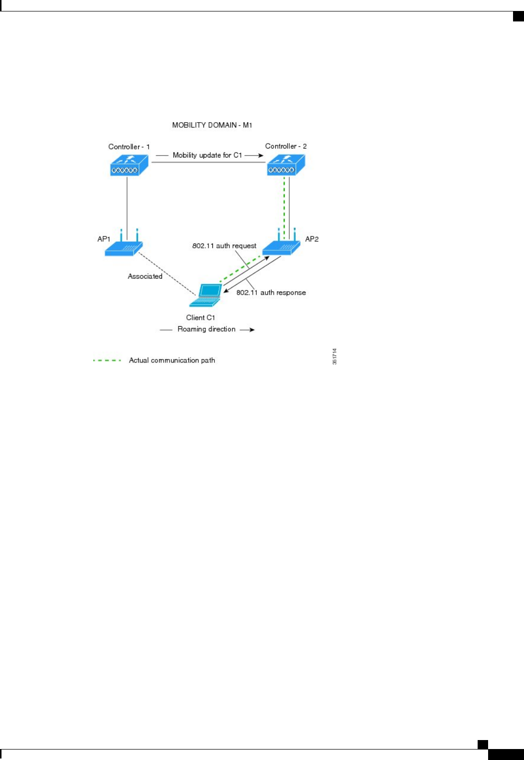
This figure shows the sequence of message exchanges that occur when Over the Air client roaming is
configured.
Figure 44: Message Exchanges when Over the Air client roaming is configured
Cisco Wireless LAN Controller Configuration Guide, Release 7.4
OL-28744-01 559
Configuring 802.11r BSS Fast Transition
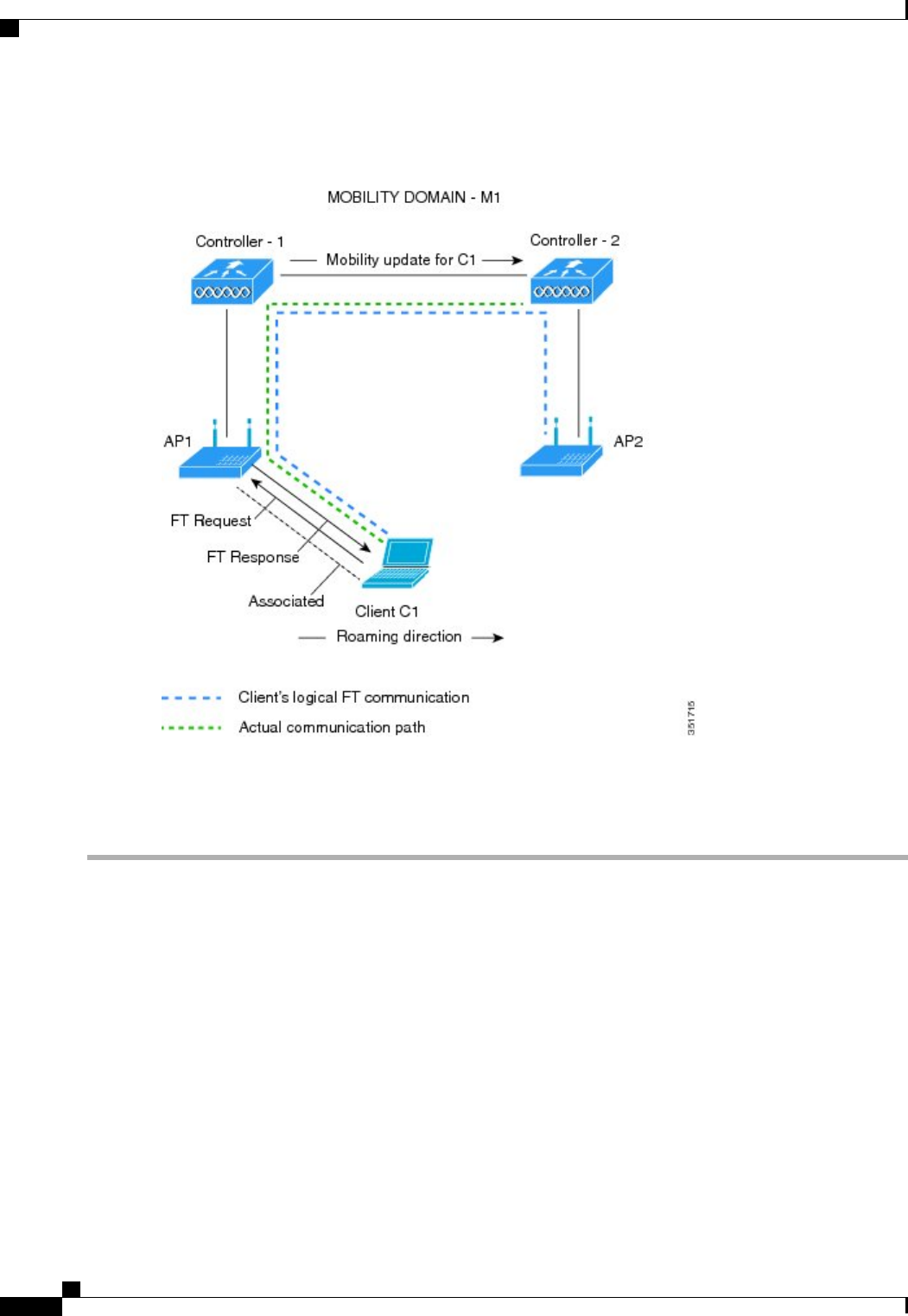
This figure shows the sequence of message exchanges that occur when Over the DS client roaming is configured.
Figure 45: Message Exchanges when Over the DS client roaming is configured
Configuring 802.11r Fast Transition (GUI)
Step 1 Choose WLANs to open the WLANs page.
Step 2 Click the WLAN ID to open the WLANs > Edit page.
Step 3 Choose the Security >Layer 2 tab.
Step 4 From the Layer 2 Security drop-down list, choose WPA+WPA2.
The Authentication Key Management parameters for Fast Transition appear.
Step 5 Select or unselect the Fast Transition check box to enable or disable Fast Transition on the WLAN.
Step 6 Select or unselect the Over the DS check box to enable or disable Fast Transition over a distributed system.
This option is available only if you enable Fast Transition.
Step 7 In the Reassociation Timeout box, enter the number of seconds after which the reassociation attempt of a client to an
AP should time out.
The valid range is 1 to 100 seconds.
This option is available only if you enable Fast Transition.
Cisco Wireless LAN Controller Configuration Guide, Release 7.4
560 OL-28744-01
Configuring 802.11r BSS Fast Transition

Step 8 Under Authentication Key Management, choose between FT 802.1X or FT PSK. Select or unselect the corresponding
check boxes to enable or disable the keys. If you select the FT PSK check box, then, from the PSK Format drop-down
list, choose ASCII or Hex and enter the key value.
Step 9 From the WPA gtk-randomize State drop-down list, choose Enable or Disable to configure the WPA group temporal
key (GTK) randomize state.
Step 10 Click Apply to save your settings.
Configuring 802.11r Fast Transition (CLI)
Step 1 To enable or disable 802.11r fast transition parameters, use the config wlan security ft {enable |disable}wlan-id
command.
By default, the fast transition is disabled.
Step 2 To enable or disable 802.11r fast transition parameters over a distributed system, use the config wlan security ft
over-the-ds {enable |disable}wlan-id command.
By default, the fast transition over a distributed system is disabled.
Step 3 To enable or disable the authentication key management for fast transition using preshared keys (PSK), use the config
wlan security wpa akm ft-psk {enable |disable}wlan-id command.
By default, the authentication key management using PSK is disabled.
Step 4 To enable or disable the authentication key management for fast transition using 802.1X, use the config wlan security
wpa akm ft-802.1X {enable |disable}wlan-id command.
By default, the authentication key management using 802.1X is disabled.
Step 5 To enable or disable 802.11r fast transition reassociation timeout, use the config wlan security ft
reassociation-timeouttimeout-in-seconds wlan-id command.
The valid range is 1 to 100 seconds. The default value of reassociation timeout is 20 seconds.
Step 6 To enable or disable the authentication key management for fast transition over a distributed system, use the config wlan
security wpa akm ft over-the-ds {enable |disable}wlan-id command.
By default, the authentication key management for fast transition over a distributed system is enabled.
Step 7 To view the fast transition configuration on a client, use the show client detailed client-mac command.
Step 8 To view the fast transition configuration on a WLAN, use the show wlan wlan-id command.
Step 9 To enable or disable debugging of fast transition events, use the debug ft events {enable |disable} command.
Step 10 To enable or disable debugging of key generation for fast transition, use the debug ft keys {enable |disable} command.
Cisco Wireless LAN Controller Configuration Guide, Release 7.4
OL-28744-01 561
Configuring 802.11r BSS Fast Transition

Troubleshooting 802.11r BSS Fast Transition
ResolutionSymptom
Check if the WLAN has FT enabled. If so, non-FT
WLAN will need to be created.
Non-802.11r legacy clients are no longer connecting.
Check if WPA2 is being used (802.1x / PSK). FT is
supported only on WPA2 and OPEN SSIDs.
When configuring WLAN, the FT setup options are
not shown.
Check if the reassociation timeout has been lowered
from the default of 20 by navigating to WLANs >
WLAN Name >Security >Layer 2 on the controller
GUI.
802.11r clients appear to reauthenticate when they do
a Layer 2 roam to a new controller.
Configuring MAC Authentication Failover to 802.1X Authentication
You can configure the controller to start 802.1X authentication when MAC authentication with static WEP
for the client fails. If the RADIUS server rejects an access request from a client instead of deauthenticating
the client, the controller can force the client to undergo an 802.1X authentication. If the client fails the 802.1X
authentication too, then the client is deauthenticated.
If MAC authentication is successful and the client requests for an 802.1X authentication, the client has to pass
the 802.1X authentication to be allowed to send data traffic. If the client does not choose an 802.1X
authentication, the client is declared to be authenticated if the client passes the MAC authentication.
Configuring MAC Authentication Failover to 802.1x Authentication (GUI)
Step 1 Choose WLANs >WLAN ID to open the WLANs > Edit page.
Step 2 In the Security tab, click the Layer 2 tab.
Step 3 Select the MAC Filtering check box.
Step 4 Select the Mac Auth or Dot1x check box.
Configuring MAC Authentication Failover to 802.1X Authentication (CLI)
To configure MAC authentication failover to 802.1X authentication, enter this command:
config wlan security 802.1X on-macfilter-failure {enable |disable}wlan-id
Cisco Wireless LAN Controller Configuration Guide, Release 7.4
562 OL-28744-01
Configuring MAC Authentication Failover to 802.1X Authentication

Configuring 802.11w
Restrictions for 802.11w
•Cisco's legacy Management Frame Protection is not related to the 802.11w standard that is implemented
in the 7.4 release.
•The 802.11w standard is supported on all 802.11n capable APs except those that are configured for
FlexConnect operation.
•The 802.11w standard is supported on the following Cisco Wireless LAN Controller model series: 2500,
5500, 8500, and WiSM2.
The 802.11w standard is not supported on the following Cisco Wireless LAN Controller models: Flex
7500 and Virtual Wireless LAN Controller.
•When 802.11w is set to optional and the keys are set, the AKM suite still shows 802.11w as disabled;
this is a Wi-Fi limitation.
•802.11w cannot be applied on an open WLAN, WEP-encrypted WLAN, or a TKIP-encrypted WLAN.
•The WLAN on which 802.11w is configured must have either WPA2-PSK or WPA2-802.1x security
configured.
Information About 802.11w
Wi-Fi is a broadcast medium that enables any device to eavesdrop and participate either as a legitimate or
rogue device. Control and management frames such as authentication/deauthentication,
association/disassociation, beacons, and probes are used by wireless clients to select an AP and to initiate a
session for network services.
Unlike data traffic which can be encrypted to provide a level of confidentiality, these frames must be heard
and understood by all clients and therefore must be transmitted as open or unencrypted. While these frames
cannot be encrypted, they must be protected from forgery to protect the wireless medium from attacks. For
example, an attacker could spoof management frames from an AP to tear down a session between a client and
AP.
The 802.11w standard for Management Frame Protection is implemented in the 7.4 release.
The 802.11w protocol applies only to a set of robust management frames that are protected by the Management
Frame Protection (PMF) service. These include Disassociation, Deauthentication, and Robust Action frames.
Management frames that are considered as robust action and therefore protected are the following:
•Spectrum Management
•QoS
•DLS
•Block Ack
•Radio Measurement
•Fast BSS Transition
Cisco Wireless LAN Controller Configuration Guide, Release 7.4
OL-28744-01 563
Configuring 802.11w

•SA Query
•Protected Dual of Public Action
•Vendor-specific Protected
When 802.11w is implemented in the wireless medium, the following occur:
•Client protection is added by the AP adding cryptographic protection (by including the MIC information
element) to deauthentication and disassociation frames preventing them from being spoofed in a DOS
attack.
•Infrastructure protection is added by adding a Security Association (SA) teardown protection mechanism
consisting of an Association Comeback Time and an SA-Query procedure preventing spoofed association
request from disconnecting an already connected client.
Configuring 802.11w (GUI)
Step 1 Choose WLANs > WLAN ID to open the WLANs > Edit page.
Step 2 In the Security tab, choose the Layer 2 security tab.
Step 3 From the Layer 2 Security drop-down list, choose WPA+WPA2.
The 802.11w IGTK Key is derived using the 4-way handshake, which means that it can only be used on WLANs that
are configured for WPA2 security at Layer 2.
WPA2 is mandatory and encryption type must be AES. TKIP is not
valid.
Note
Step 4 Choose the PMF state from the drop-down list
The following options are available:
•Disabled—Disables 802.11w MFP protection on a WLAN
•Optional—To be used if the client supports 802.11w.
•Required—Ensures that the clients that do not support 802.11w cannot associate with the WLAN.
Step 5 If you choose the PMF state as either Optional or Required, do the following:
a) In the Comeback Timer box, enter the association comeback interval in milliseconds. It is the time within which the
access point reassociates with the client after a valid security association.
b) In the SA Query Timeout box, enter the maximum time before an Security Association (SA) query times out.
Step 6 In the Authentication Key Management section, follow these steps:
a) Select or unselect the PMF 802.1X check box to configure the 802.1X authentication for the protection of management
frames.
b) Select or unselect the PMF PSK check box to configure the preshared keys for PMF. Choose the PSK format as
either ASCII or Hexadecimal and enter the PSK.
Step 7 Click Apply.
Step 8 Click Save Configuration.
Cisco Wireless LAN Controller Configuration Guide, Release 7.4
564 OL-28744-01
Configuring 802.11w

Configuring 802.11w (CLI)
•Configure the 802.1X authentication for PMF by entering this command:
config wlan security wpa akm pmf 802.1x {enable |disable}wlan-id
•Configure the preshared key support for PMF by entering this command:
config wlan security wpa akm pmf psk {enable |disable}wlan-id
•If not done, configure a preshared key for a WLAN by entering this command:
config wlan security wpa akm psk set-key {ascii |hex}psk wlan-id
•Configure protected management frames by entering this command:
config wlan security pmf {disable |optional |required}wlan-id
•Configure the association comeback time settings by entering this command:
config wlan security pmf association-comeback timeout-in-seconds wlan-id
•Configure the SA query retry timeout settings by entering this command:
config wlan security pmf saquery-retrytimeout timeout-in-milliseconds wlan-id
•See the 802.11w configuration status for a WLAN by entering this command:
show wlan wlan-id
•Configure the debugging of PMF by entering this command:
debug pmf events {enable |disable}
Cisco Wireless LAN Controller Configuration Guide, Release 7.4
OL-28744-01 565
Configuring 802.11w

Cisco Wireless LAN Controller Configuration Guide, Release 7.4
566 OL-28744-01
Configuring 802.11w

CHAPTER 78
Configuring a WLAN for Both Static and Dynamic
WEP
•Restrictions for Configuring Static and Dynamic WEP, page 567
•Information About WLAN for Both Static and Dynamic WEP, page 567
•Configuring WPA1 +WPA2, page 569
Restrictions for Configuring Static and Dynamic WEP
•The OEAP 600 series does not support fast roaming for clients. Dual mode voice clients will experience
reduced call quality when they roam between the two spectrums on OEAP602 access point. We
recommend that you configure voice devices to only connect on one band, either 2.4 GHz or 5.0 GHz.
•The controller software supports CCX versions 1 through 5. CCX support is enabled automatically for
every WLAN on the controller and cannot be disabled. The controller stores the CCX version of the
client in its client database and uses it to limit client functionality. Clients must support CCXv4 or v5
in order to use CCKM. For more information about CCX, see the Configuring Cisco Client Extensions
section.
•In a unified architecture where multiple VLAN clients are supported for a WGB, you also need to
configure encryption cipher suite and WEP keys globally, when the WEP encryption is enabled on the
WGB. Otherwise, multicast traffic for wired VLAN clients fail.
Information About WLAN for Both Static and Dynamic WEP
You can configure up to four WLANs to support static WEP keys, and you can also configure dynamic WEP
on any of these static-WEP WLANs. Follow these guidelines when configuring a WLAN for both static and
dynamic WEP:
•The static WEP key and the dynamic WEP key must be the same length.
•When you configure both static and dynamic WEP as the Layer 2 security policy, no other security
policies can be specified. That is, you cannot configure web authentication. However, when you configure
either static or dynamic WEP as the Layer 2 security policy, you can configure web authentication.
Cisco Wireless LAN Controller Configuration Guide, Release 7.4
OL-28744-01 567

WPA1 and WPA2
Wi-Fi Protected Access (WPA or WPA1) and WPA2 are standards-based security solutions from the Wi-Fi
Alliance that provide data protection and access control for wireless LAN systems. WPA1 is compatible with
the IEEE 802.11i standard but was implemented prior to the standard’s ratification; WPA2 is the Wi-Fi
Alliance's implementation of the ratified IEEE 802.11i standard.
By default, WPA1 uses Temporal Key Integrity Protocol (TKIP) and message integrity check (MIC) for data
protection while WPA2 uses the stronger Advanced Encryption Standard encryption algorithm using Counter
Mode with Cipher Block Chaining Message Authentication Code Protocol (AES-CCMP). Both WPA1 and
WPA2 use 802.1X for authenticated key management by default. However, these options are also available:
•802.1X—The standard for wireless LAN security, as defined by IEEE, is called 802.1X for 802.11, or
simply 802.1X. An access point that supports 802.1X acts as the interface between a wireless client and
an authentication server, such as a RADIUS server, to which the access point communicates over the
wired network. If 802.1X is selected, only 802.1X clients are supported.
•PSK—When you choose PSK (also known as WPA preshared key or WPA passphrase), you need to
configure a preshared key (or a passphrase). This key is used as the pairwise master key (PMK) between
the clients and the authentication server.
•CCKM—Cisco Centralized Key Management (CCKM) uses a fast rekeying technique that enables
clients to roam from one access point to another without going through the controller, typically in under
150 milliseconds (ms). CCKM reduces the time required by the client to mutually authenticate with the
new access point and derive a new session key during reassociation. CCKM fast secure roaming ensures
that there is no perceptible delay in time-sensitive applications such as wireless Voice over IP (VoIP),
enterprise resource planning (ERP), or Citrix-based solutions. CCKM is a CCXv4-compliant feature.
If CCKM is selected, only CCKM clients are supported.
When CCKM is enabled, the behavior of access points differs from the controller's for fast roaming in
the following ways:
◦If an association request sent by a client has CCKM enabled in a Robust Secure Network Information
Element (RSN IE) but CCKM IE is not encoded and only PMKID is encoded in RSN IE, then the
controller does not do a full authentication. Instead, the controller validates the PMKID and does
a four-way handshake.
◦If an association request sent by a client has CCKM enabled in RSN IE but CCKM IE is not
encoded and only PMKID is encoded in RSN IE, then AP does a full authentication. The access
point does not use PMKID sent with the association request when CCKM is enabled in RSN IE.
•802.1X+CCKM—During normal operation, 802.1X-enabled clients mutually authenticate with a new
access point by performing a complete 802.1X authentication, including communication with the main
RADIUS server. However, when you configure your WLAN for 802.1X and CCKM fast secure roaming,
CCKM-enabled clients securely roam from one access point to another without the need to reauthenticate
to the RADIUS server. 802.1X+CCKM is considered optional CCKM because both CCKM and
non-CCKM clients are supported when this option is selected.
On a single WLAN, you can allow WPA1, WPA2, and 802.1X/PSK/CCKM/802.1X+CCKM clients to join.
All of the access points on such a WLAN advertise WPA1, WPA2, and 802.1X/PSK/CCKM/ 802.1X+CCKM
information elements in their beacons and probe responses. When you enable WPA1 and/or WPA2, you can
also enable one or two ciphers, or cryptographic algorithms, designed to protect data traffic. Specifically, you
can enable AES and/or TKIP data encryption for WPA1 and/or WPA2. TKIP is the default value for WPA1,
and AES is the default value for WPA2.
Cisco Wireless LAN Controller Configuration Guide, Release 7.4
568 OL-28744-01
Information About WLAN for Both Static and Dynamic WEP

Configuring WPA1 +WPA2
Configuring WPA1+WPA2 (GUI)
Step 1 Choose WLANs to open the WLANs page.
Step 2 Click the ID number of the desired WLAN to open the WLANs > Edit page.
Step 3 Choose the Security and Layer 2 tabs to open the WLANs > Edit (Security > Layer 2) page.
Step 4 Choose WPA+WPA2 from the Layer 2 Security drop-down list.
Step 5 Under WPA+WPA2 Parameters, select the WPA Policy check box to enable WPA1, select the WPA2 Policy check
box to enable WPA2, or select both check boxes to enable both WPA1 and WPA2.
The default value is disabled for both WPA1 and WPA2. If you leave both WPA1 and WPA2 disabled, the
access points advertise in their beacons and probe responses information elements only for the authentication
key management method that you choose in Step 7.
Note
Step 6 Select the AES check box to enable AES data encryption or the TKIP check box to enable TKIP data encryption for
WPA1, WPA2, or both. The default values are TKIP for WPA1 and AES for WPA2.
Step 7 Choose one of the following key management methods from the Auth Key Mgmt drop-down list: 802.1X,CCKM,PSK,
or 802.1X+CCKM.
Cisco OEAP 600 does not support CCKM. You must choose either 802.1X or
PSK.
Note
For Cisco OEAP 600, the TKIP and AES security encryption settings must be identical for WPA and
WPA2.
Note
Step 8 If you chose PSK in Step 7, choose ASCII or HEX from the PSK Format drop-down list and then enter a preshared key
in the blank text box. WPA preshared keys must contain 8 to 63 ASCII text characters or 64 hexadecimal characters.
The PSK parameter is a set-only parameter. The value set for the PSK key is not visible to the user for security
reasons. For example, if you selected HEX as the key format when setting the PSK key, and later when you
view the parameters of this WLAN, the value shown is the default value. The default is ASCII.
Note
Step 9 Click Apply to commit your changes.
Step 10 Click Save Configuration to save your changes.
Configuring WPA1+WPA2 (CLI)
Step 1 Disable the WLAN by entering this command:
config wlan disable wlan_id
Step 2 Enable or disable WPA for the WLAN by entering this command:
config wlan security wpa {enable |disable}wlan_id
Step 3 Enable or disable WPA1 for the WLAN by entering this command:
config wlan security wpa wpa1 {enable |disable}wlan_id
Step 4 Enable or disable WPA2 for the WLAN by entering this command:
Cisco Wireless LAN Controller Configuration Guide, Release 7.4
OL-28744-01 569
Configuring WPA1 +WPA2

config wlan security wpa wpa2 {enable |disable}wlan_id
Step 5 Enable or disable AES or TKIP data encryption for WPA1 or WPA2 by entering one of these commands:
•config wlan security wpa wpa1 ciphers {aes |tkip} {enable | disable} wlan_id
•config wlan security wpa wpa2 ciphers {aes |tkip} {enable |disable}wlan_id
The default values are TKIP for WPA1 and AES for WPA2.
When you have VLAN configuration on WGB, you need to configure the encryption cipher mode and keys for a particular
VLAN, for example, encryption vlan 80 mode ciphers tkip. Then, you need configure the encryption cipher mode
globally on the multicast interface by entering the following command: encryption mode ciphers tkip.
Step 6 Enable or disable 802.1X, PSK, or CCKM authenticated key management by entering this command:
config wlan security wpa akm {802.1X |psk |cckm} {enable | disable} wlan_id
The default value is 802.1X.
Step 7 If you enabled PSK in Step 6, enter this command to specify a preshared key:
config wlan security wpa akm psk set-key {ascii |hex}psk-key wlan_id
WPA preshared keys must contain 8 to 63 ASCII text characters or 64 hexadecimal characters.
Step 8 Enable or disable authentication key management suite for fast transition by entering this command:
config wlan security wpa akm ft {802.1X |psk} {enable |disable}wlan_id
You can now choose between the PSK and the fast transition PSK as the AKM
suite.
Note
Step 9 Enable or disable randomization of group temporal keys (GTK) between AP and clients by entering this command:
config wlan security wpa gtk-random {enable |disable}wlan_id
Step 10 If you enabled WPA2 with 802.1X authenticated key management or WPA1 or WPA2 with CCKM authenticated key
management, the PMK cache lifetime timer is used to trigger reauthentication with the client when necessary. The timer
is based on the timeout value received from the AAA server or the WLAN session timeout setting. To see the amount
of time remaining before the timer expires, enter this command:
show pmk-cache all
If you enabled WPA2 with 802.1X authenticated key management, the controller supports both opportunistic PMKID
caching and sticky (or non-opportunistic) PMKID caching. In sticky PMKID caching (SKC), the client stores multiple
PMKIDs, a different PMKID for every AP it associates with. Opportunistic PMKID caching (OKC) stores only one
PMKID per client. By default, the controller supports OKC.
Step 11 Enable the WLAN by entering this command:
config wlan enable wlan_id
Step 12 Save your settings by entering this command:
save config
Cisco Wireless LAN Controller Configuration Guide, Release 7.4
570 OL-28744-01
Configuring WPA1 +WPA2

CHAPTER 79
Configuring Sticky Key Caching
•Information About Sticky Key Caching, page 571
•Restrictions for Sticky Key Caching, page 571
•Configuring Sticky Key Caching (CLI), page 572
Information About Sticky Key Caching
The controller supports sticky key caching (SKC). With sticky key caching, the client receives and stores a
different PMKID for every AP it associates with. The APs also maintain a database of the PMKID issued to
the client.
In SKC, the client stores each Pairwise Master Key ID (PMKID) against a Pairwise Master Key Security
Association (PMKSA). When a client finds an AP for which it has the PMKSA, it sends the PMKID in the
association request to the AP. If the PMKSA is alive in the AP, the AP provides support for fast roaming. In
SKC, full authentication is done on each new AP to which the client associates and the client must keep the
PMKSA associated with all APs. For SKC, PMKSA is a per AP cache that the client stores and PMKSA is
precalculated based on the BSSID of the new AP.
Restrictions for Sticky Key Caching
•The controller supports SKC for up to eight APs per client. If a client roams to more than 8 APs per
session, the old APs are removed to store the newly cached entries when the client roams. We recommend
that you do not use SKC for large scale deployments.
•SKC works only on WPA2-enabled WLANs.
•SKC does not work across controllers in a mobility group.
•SKC works only on local mode APs.
Cisco Wireless LAN Controller Configuration Guide, Release 7.4
OL-28744-01 571

Configuring Sticky Key Caching (CLI)
Step 1 Disable the WLAN by entering this command:
config wlan disable wlan_id
Step 2 Enable sticky key caching by entering this command:
config wlan security wpa wpa2 cache sticky enable wlan_id
By default, SKC is disabled and opportunistic key caching (OKC) is enabled.
SKC works only on WPA2 enabled
WLANs.
Note
You can check if SKC is enabled by entering this command:
show wlan wlan_id
Information similar to the following appears:
WLAN Identifier.................................. 2
Profile Name..................................... new
Network Name (SSID).............................. new
Status........................................... Disabled
MAC Filtering.................................... Disabled
Security
802.11 Authentication:........................ Open System
Static WEP Keys............................... Disabled
802.1X........................................ Disabled
Wi-Fi Protected Access (WPA/WPA2)............. Enabled
WPA (SSN IE)............................... Disabled
WPA2 (RSN IE).............................. Enabled
TKIP Cipher............................. Disabled
AES Cipher.............................. Enabled
Auth Key Management
802.1x.................................. Disabled
PSK..................................... Enabled
CCKM.................................... Disabled
FT(802.11r)............................. Disabled
FT-PSK(802.11r)......................... Disabled
SKC Cache Support......................... Enabled
FT Reassociation Timeout................... 20
FT Over-The-Air mode....................... Enabled
FT Over-The-Ds mode........................ Enabled
CCKM tsf Tolerance............................... 1000
Wi-Fi Direct policy configured................ Disabled
EAP-Passthrough............................... Disabled
Step 3 Enable the WLAN by entering this command:
config wlan enable wlan_id
Step 4 Save your settings by entering this command:
save config
Cisco Wireless LAN Controller Configuration Guide, Release 7.4
572 OL-28744-01
Configuring Sticky Key Caching (CLI)

Cisco Wireless LAN Controller Configuration Guide, Release 7.4
OL-28744-01 573
Configuring Sticky Key Caching (CLI)

Cisco Wireless LAN Controller Configuration Guide, Release 7.4
574 OL-28744-01
Configuring Sticky Key Caching (CLI)

CHAPTER 80
Configuring CKIP
•Information About CKIP, page 575
•Configuring CKIP (GUI), page 576
•Configuring CKIP (CLI), page 576
Information About CKIP
Cisco Key Integrity Protocol (CKIP) is a Cisco-proprietary security protocol for encrypting 802.11 media.
CKIP improves 802.11 security in infrastructure mode using key permutation, a message integrity check
(MIC), and a message sequence number. Software release 4.0 or later releases support CKIP with a static key.
For this feature to operate correctly, you must enable Aironet information elements (IEs) for the WLAN.
A lightweight access point advertises support for CKIP in beacon and probe response packets by adding an
Aironet IE and setting one or both of the CKIP negotiation bits (key permutation and multi-modular hash
message integrity check [MMH MIC]). Key permutation is a data encryption technique that uses the basic
encryption key and the current initialization vector (IV) to create a new key. MMH MIC prevents bit-flip
attacks on encrypted packets by using a hash function to compute message integrity code.
The CKIP settings specified in a WLAN are mandatory for any client attempting to associate. If the WLAN
is configured for both CKIP key permutation and MMH MIC, the client must support both. If the WLAN is
configured for only one of these features, the client must support only the CKIP feature.
CKIP requires that 5-byte and 13-byte encryption keys be expanded to 16-byte keys. The algorithm to perform
key expansion occurs at the access point. The key is appended to itself repeatedly until the length reaches 16
bytes. All lightweight access points support CKIP.
CKIP is supported for use only with static WEP. It is not supported for use with dynamic WEP. Therefore,
a wireless client that is configured to use CKIP with dynamic WEP is unable to associate to a WLAN that
is configured for CKIP. We recommend that you use either dynamic WEP without CKIP (which is less
secure) or WPA/WPA2 with TKIP or AES (which are more secure).
Note
Cisco Wireless LAN Controller Configuration Guide, Release 7.4
OL-28744-01 575

Configuring CKIP (GUI)
Step 1 Choose WLANs to open the WLANs page.
Step 2 Click the ID number of the desired WLAN to open the WLANs > Edit page.
Step 3 Choose the Advanced tab.
Step 4 Select the Aironet IE check box to enable Aironet IEs for this WLAN and click Apply.
Step 5 Choose the General tab.
Step 6 Unselect the Status check box, if selected, to disable this WLAN and click Apply.
Step 7 Choose the Security and Layer 2 tabs to open the WLANs > Edit (Security > Layer 2) page.
Step 8 Choose CKIP from the Layer 2 Security drop-down list.
Step 9 Under CKIP Parameters, choose the length of the CKIP encryption key from the Key Size drop-down list.The range is
Not Set, 40 bits, or 104 bits and the default is Not Set.
Step 10 Choose the number to be assigned to this key from the Key Index drop-down list. You can configure up to four keys.
Step 11 From the Key Format drop-down list, choose ASCII or HEX and then enter an encryption key in the Encryption Key
text box. 40-bit keys must contain 5 ASCII text characters or 10 hexadecimal characters. 104-bit keys must contain 13
ASCII text characters or 26 hexadecimal characters.
Step 12 Select the MMH Mode check box to enable MMH MIC data protection for this WLAN. The default value is disabled
(or unselected).
Step 13 Select the Key Permutation check box to enable this form of CKIP data protection. The default value is disabled (or
unselected).
Step 14 Click Apply to commit your changes.
Step 15 Choose the General tab.
Step 16 Select the Status check box to enable this WLAN.
Step 17 Click Apply to commit your changes.
Step 18 Click Save Configuration to save your changes.
Configuring CKIP (CLI)
Step 1 Disable the WLAN by entering this command:
config wlan disable wlan_id
Step 2 Enable Aironet IEs for this WLAN by entering this command:
config wlan ccx aironet-ie enable wlan_id
Step 3 Enable or disable CKIP for the WLAN by entering this command:
config wlan security ckip {enable |disable}wlan_id
Step 4 Specify a CKIP encryption key for the WLAN by entering this command:
config wlan security ckip akm psk set-key wlan_id {40 |104} {hex |ascii}key key_index
Cisco Wireless LAN Controller Configuration Guide, Release 7.4
576 OL-28744-01
Configuring CKIP (GUI)

Step 5 Enable or disable CKIP MMH MIC for the WLAN by entering this command:
config wlan security ckip mmh-mic {enable |disable}wlan_id
Step 6 Enable or disable CKIP key permutation for the WLAN by entering this command:
config wlan security ckip kp {enable |disable}wlan_id
Step 7 Enable the WLAN by entering this command:
config wlan enable wlan_id
Step 8 Save your settings by entering this command:
save config
Cisco Wireless LAN Controller Configuration Guide, Release 7.4
OL-28744-01 577
Configuring CKIP (CLI)

Cisco Wireless LAN Controller Configuration Guide, Release 7.4
578 OL-28744-01
Configuring CKIP (CLI)

CHAPTER 81
Configuring Layer 3 Security
•Configuring Layer 3 Security Using VPN Passthrough, page 579
•Configuring Layer 3 Security Using Web Authentication, page 580
Configuring Layer 3 Security Using VPN Passthrough
Restrictions for Layer 3 Security Using VPN Passthrough
•Layer 2 Tunnel Protocol (L2TP) and IPsec are not supported on controllers.
•Layer 3 security settings are not supported when you disable the client IP address on a WLAN.
•The VPN Passthrough option is not available on Cisco 5500 Series Controllers. However, you can
replicate this functionality on the controller by creating an open WLAN using an ACL.
Information About VPN Passthrough
The controller supports VPN passthrough or the “passing through”of packets that originate from VPN clients.
An example of VPN passthrough is your laptop trying to connect to the VPN server at your corporate office.
Cisco Wireless LAN Controller Configuration Guide, Release 7.4
OL-28744-01 579

Configuring VPN Passthrough
Configuring VPN Passthrough (GUI)
Step 1 Choose WLANs to open the WLANs page.
Step 2 Click the ID number of the WLAN for which you want to configure VPN passthrough. The WLANs > Edit page appears.
Step 3 Choose the Security and Layer 3 tabs to open the WLANs > Edit (Security > Layer 3) page.
Step 4 From the Layer 3 Security drop-down list, choose VPN Pass-Through.
Step 5 In the VPN Gateway Address text box, enter the IP address of the gateway router that is terminating the VPN tunnels
initiated by the client and passed through the controller.
Step 6 Click Apply to commit your changes.
Step 7 Click Save Configuration to save your settings.
Configuring VPN Passthrough (CLI)
Use these commands to configure VPN passthrough:
•config wlan security passthru {enable |disable}wlan_id gateway
For gateway, enter the IP address of the router that is terminating the VPN tunnel.
•Verify that the passthrough is enabled by entering this command:
show wlan
Configuring Layer 3 Security Using Web Authentication
Prerequisites for Configuring Web Authentication on a WLAN
•To initiate HTTP/HTTPS web authentication redirection, always use only HTTP URL and not HTTPS
URL.
•If the CPU ACLs are configured to block HTTP / HTTPS traffic, after the successful web login
authentication, there could be a failure in the redirection page.
•Before enabling web authentication, make sure that all proxy servers are configured for ports other than
port 53.
•When you enable web authentication for a WLAN, a message appears indicating that the controller
forwards DNS traffic to and from wireless clients prior to authentication. We recommend that you have
a firewall or intrusion detection system (IDS) behind your guest VLAN to regulate DNS traffic and to
prevent and detect any DNS tunneling attacks.
•If the web authentication is enabled on the WLAN and you also have the CPU ACL rules, the client-based
web authentication rules take higher precedence as long as the client is unauthenticated (in the
Cisco Wireless LAN Controller Configuration Guide, Release 7.4
580 OL-28744-01
Configuring Layer 3 Security Using Web Authentication

webAuth_Reqd state). Once the client goes to the RUN state, the CPU ACL rules get applied. Therefore,
if the CPU ACL rules are enabled in the controller, an allow rule for the virtual interface IP is required
(in any direction) with the following conditions:
◦When the CPU ACL does not have an allow ACL rule for both directions.
◦When an allow ALL rule exists, but also a DENY rule for port 443 or 80 of higher precedence.
•The allow rule for the virtual IP should be for TCP protocol and port 80 (if secureweb is disabled) or
port 443 (if secureweb is enabled). This process is required to allow client’s access to the virtual interface
IP address, post successful authentication when the CPU ACL rules are in place.
Restrictions for Configuring Web Authentication on a WLAN
•Web authentication is supported only with these Layer 2 security policies: open authentication, open
authentication+WEP, and WPA-PSK. With the 7.4 release, web authentication is supported for use with
802.1X.
•Special charecters are not supported in the username field for web-authentication.
•When clients connect to a WebAuth SSID and a preauthorization ACL configured to allow VPN users,
the clients will get disconnected from the SSID every few minutes. Webauth SSIDs must not connect
without authenticating on the web page.
You can select the following identity stores to authenticate web-auth user, under WLANs > Security
> AAA servers > Authentication priority order for web-auth user section:
•Local
•RADIUS
•LDAP
If multiple identity stores are selected, then the controller checks each identity store in the list, in the
order specified, from top to bottom, until authentication for the user succeeds. The authentication fails,
if the controller reaches the end of the list and user remains un-authenticated in any of the identity stores.
Information About Web Authentication
WLANs can use web authentication only if VPN passthrough is not enabled on the controller. Web
authentication is simple to set up and use and can be used with SSL to improve the overall security of the
WLAN.
Cisco Wireless LAN Controller Configuration Guide, Release 7.4
OL-28744-01 581
Configuring Layer 3 Security Using Web Authentication

Configuring Web Authentication
Configuring Web Authentication (GUI)
Step 1 Choose WLANs to open the WLANs page.
Step 2 Click the ID number of the WLAN for which you want to configure web authentication. The WLANs > Edit page
appears.
Step 3 Choose the Security and Layer 3 tabs to open the WLANs > Edit (Security > Layer 3) page.
Step 4 Select the Web Policy check box.
Step 5 Make sure that the Authentication option is selected.
Step 6 Click Apply to commit your changes.
Step 7 Click Save Configuration to save your settings.
Configuring Web Authentication (CLI)
Step 1 Enable or disable web authentication on a particular WLAN by entering this command:
config wlan security web-auth {enable |disable}wlan_id
Step 2 Release the guest user IP address when the web authentication policy timer expires and prevent the guest user from
acquiring an IP address for 3 minutes by entering this command:
config wlan webauth-exclude wlan_id {enable |disable}
The default value is disabled. This command is applicable when you configure the internal DHCP scope on the controller.
By default, when the web authentication timer expires for a guest user, the user can immediately reassociate to the same
IP address before another guest user can acquire it. If there are many guest users or limited IP addresses in the DHCP
pool, some guest users might not be able to acquire an IP address.
When you enable this feature on the guest WLAN, the guest user’s IP address is released when the web authentication
policy timer expires and the guest user is excluded from acquiring an IP address for 3 minutes. The IP address is available
for another guest user to use. After 3 minutes, the excluded guest user can reassociate and acquire an IP address, if
available.
Step 3 See the status of web authentication by entering this command:
show wlan wlan_id
Cisco Wireless LAN Controller Configuration Guide, Release 7.4
582 OL-28744-01
Configuring Layer 3 Security Using Web Authentication

CHAPTER 82
Configuring Captive Bypassing
•Information About Captive Bypassing, page 583
•Configuring Captive Bypassing (CLI), page 584
Information About Captive Bypassing
WISPr is a draft protocol that enables users to roam between different wireless service providers. Some devices
(For example, Apple iOS devices) have a mechanism using which they can determine if the device is connected
to Internet, based on an HTTP WISPr request made to a designated URL. This mechanism is used for the
device to automatically open a web browser when a direct connection to the internet is not possible. This
enables the user to provide his credentials to access the internet. The actual authentication is done in the
background every time the device connects to a new SSID.
This HTTP request triggers a web authentication interception in the controller as any other page requests are
performed by a wireless client. This interception leads to a web authentication process, which will be completed
normally. If the web authentication is being used with any of the controller splash page features (URL provided
by a configured RADIUS server), the splash page may never be displayed because the WISPr requests are
made at very short intervals, and as soon as one of the queries is able to reach the designated server, any web
redirection or splash page display process that is performed in the background is aborted, and the device
processes the page request, thus breaking the splash page functionality.
For example, Apple introduced an iOS feature to facilitate network access when captive portals are present.
This feature detects the presence of a captive portal by sending a web request on connecting to a wireless
network. This request is directed to http://www.apple.com/library/test/success.html for Apple IOS version 6
and older, and to several possible target URLs for Apple IOS version 7 and later. If a response is received,
then the Internet access is assumed to be available and no further interaction is required. If no response is
received, then the Internet access is assumed to be blocked by the captive portal and Apple’s Captive Network
Assistant (CNA) auto-launches the pseudo-browser to request portal login in a controlled window. The CNA
may break when redirecting to an ISE captive portal. The controller prevents this pseudo-browser from popping
up.
You can now configure the controller to bypass WISPr detection process, so the web authentication interception
is only done when a user requests a web page leading to splash page load in user context, without the WISPr
detection being performed in the background.
Cisco Wireless LAN Controller Configuration Guide, Release 7.4
OL-28744-01 583

Configuring Captive Bypassing (CLI)
Use these commands to configure captive bypassing:
•config network web-auth captive-bypass {enable |disable}—Enables or disables the controller to
support bypass of captive portals at the network level.
•show network summary—Displays the status for the WISPr protocol detection feature.
Cisco Wireless LAN Controller Configuration Guide, Release 7.4
584 OL-28744-01
Configuring Captive Bypassing (CLI)

CHAPTER 83
Configuring a Fallback Policy with MAC Filtering
and Web Authentication
•Information About Fallback Policy with MAC Filtering and Web Authentication, page 585
•Configuring a Fallback Policy with MAC Filtering and Web Authentication (GUI), page 585
•Configuring a Fallback Policy with MAC Filtering and Web Authentication (CLI), page 586
Information About Fallback Policy with MAC Filtering and Web Authentication
You can configure a fallback policy mechanism that combines Layer 2 and Layer 3 security. In a scenario
where you have both MAC filtering and web authentication implemented, when a client tries to connect to a
WLAN using the MAC filter (RADIUS server), if the client fails the authentication, you can configure the
authentication to fall back to web authentication. When a client passes the MAC filter authentication, the web
authentication is skipped and the client is connected to the WLAN. With this feature, you can avoid
disassociations based on only a MAC filter authentication failure.
Configuring a Fallback Policy with MAC Filtering and Web Authentication
(GUI)
Before configuring a fallback policy, you must have MAC filtering enabled.Note
Step 1 Choose WLANs to open the WLANs page.
Step 2 Click the ID number of the WLAN for which you want to configure the fallback policy for web authentication. The
WLANs > Edit page appears.
Step 3 Choose the Security and Layer 3 tabs to open the WLANs > Edit (Security > Layer 3) page.
Step 4 From the Layer 3 Security drop-down list, choose None.
Step 5 Select the Web Policy check box.
Cisco Wireless LAN Controller Configuration Guide, Release 7.4
OL-28744-01 585

The controller forwards DNS traffic to and from wireless clients prior to authentication.
The following options are displayed:
Note
•Authentication
•Passthrough
•Conditional Web Redirect
•Splash Page Web Redirect
•On MAC Filter Failure
Step 6 Click On MAC Filter Failure.
Step 7 Click Apply to commit your changes.
Step 8 Click Save Configuration to save your settings.
Configuring a Fallback Policy with MAC Filtering and Web Authentication
(CLI)
Before configuring a fallback policy, you must have MAC filtering enabled. To know more about how to
enable MAC filtering, see the Information About MAC Filtering of WLANs, on page 541 section.
Note
Step 1 Enable or disable web authentication on a particular WLAN by entering this command:
config wlan security web-auth on-macfilter-failure wlan-id
Step 2 See the web authentication status by entering this command:
show wlan wlan_id
FT Over-The-Ds mode.............................. Enabled
CKIP ......................................... Disabled
IP Security................................... Disabled
IP Security Passthru.......................... Disabled
Web Based Authentication...................... Enabled-On-MACFilter-Failure
ACL............................................. Unconfigured
Web Authentication server precedence:
1............................................... local
2............................................... radius
3............................................... ldap
Cisco Wireless LAN Controller Configuration Guide, Release 7.4
586 OL-28744-01
Configuring a Fallback Policy with MAC Filtering and Web Authentication (CLI)

CHAPTER 84
Assigning QoS Profiles
•Information About QoS Profiles, page 587
•Assigning a QoS Profile to a WLAN (GUI), page 588
•Assigning a QoS Profile to a WLAN (CLI), page 589
Information About QoS Profiles
Cisco UWN solution WLANs support four levels of QoS: Platinum/Voice, Gold/Video, Silver/Best Effort
(default), and Bronze/Background. You can configure the voice traffic WLAN to use Platinum QoS, assign
the low-bandwidth WLAN to use Bronze QoS, and assign all other traffic between the remaining QoS levels.
The WLAN QoS level defines a specific 802.11e user priority (UP) for over-the-air traffic. This UP is used
to derive the over-the-wire priorities for non-WMM traffic, and it also acts as the ceiling when managing
WMM traffic with various levels of priorities.
The wireless rate limits can be defined on both upstream and downstream traffic. Rate limits can be defined
per SSID and/or specified as a maximum rate limit for all clients. These rate limits can be individually
configured.
The access point uses this QoS-profile-specific UP in accordance with the values in the following table to
derive the IP DSCP value that is visible on the wired LAN.
Table 18: Access Point QoS Translation Values
IEEE 802.11e
UP
AVVID 802.1pQoS ProfileAVVID IP DSCPAVVID Traffic Type
77Platinum56 (CS7)Network control
76Platinum48 (CS6)Inter-network control
(CAPWAP control,
802.11 management)
65Platinum46 (EF)Voice
54Gold34 (AF41)Interactive video
Cisco Wireless LAN Controller Configuration Guide, Release 7.4
OL-28744-01 587

IEEE 802.11e
UP
AVVID 802.1pQoS ProfileAVVID IP DSCPAVVID Traffic Type
43Gold26 (AF31)Mission critical
32Silver18 (AF21)Transactional
21Bronze10 (AF11)Bulk data
00Silver0 (BE)Best effort
10Bronze2Scavenger
The IEEE 802.11e UP value for DSCP values that are not mentioned in the table is calculated by considering
3 MSB bits of DSCP.
For example, the IEEE 802.11e UP value for DSCP 32 (100 000 in binary), would be the decimal equivalent
of the MSB (100) which is 4. The 802.11e UP value of DSCP 32 is 4.
Note
Assigning a QoS Profile to a WLAN (GUI)
Before You Begin
If you have not already done so, configure one or more QoS profiles using the instructions in the Configuring
QoS Profiles (GUI) section.
Step 1 Choose WLANs to open the WLANs page.
Step 2 Click the ID number of the WLAN to which you want to assign a QoS profile.
Step 3 When the WLANs > Edit page appears, choose the QoS tab.
Step 4 From the Quality of Service (QoS) drop-down list, choose one of the following:
•Platinum (voice)
•Gold (video)
•Silver (best effort)
•Bronze (background)
Silver (best effort) is the default
value.
Note
Step 5 To define the data rates on a per-user basis, do the following:
a) Define the average data rate for TCP traffic per user by entering the rate in Kbps in the Average Data Rate text boxes.
A value of 0 indicates that the value specified in the selected QoS profile will take effect.
Cisco Wireless LAN Controller Configuration Guide, Release 7.4
588 OL-28744-01
Assigning a QoS Profile to a WLAN (GUI)

b) Define the peak data rate for TCP traffic per user by entering the rate in Kbps in the Burst Data Rate text boxes. A
value of 0 indicates that the value specified in the selected QoS profile will take effect.
The burst data rate should be greater than or equal to the average data rate. Otherwise, the QoS policy may
block traffic to and from the wireless client.
Ensure that you configure the average data rate before you configure the burst data rate.
Note
c) Define the average real-time rate for UDP traffic per user by entering the rate in Kbps in the Average Real-Time
Rate text boxes. A value of 0 indicates that the value specified in the selected QoS profile will take effect.
Average Data Rate is used to measure TCP traffic while Average Real-time rate is used for UDP traffic.
They are measured in kbps for all the entries. The values for Average Data Rate and Average Real-time rate
can be different because they are applied to different upper layer protocols such as TCP and UDP. These
different values for the rates do not impact the bandwidth.
Note
d) Define the peak real-time rate for UDP traffic per user by entering the rate in Kbps in the Burst Real-Time Rate text
boxes. A value of 0 indicates that the value specified in the selected QoS profile will take effect.
The burst real-time rate should be greater than or equal to the average real-time rate. Otherwise, the QoS
policy may block traffic to and from the wireless client.
Note
Step 6 To define the data rates on a per-SSID basis, do the following:
a) Define the average data rate TCP traffic per SSID by entering the rate in Kbps in the Average Data Rate text boxes.
A value of 0 indicates that the value specified in the selected QoS profile will take effect.
b) Define the peak data rate for TCP traffic per SSID by entering the rate in Kbps in the Burst Data Rate text boxes. A
value of 0 indicates that the value specified in the selected QoS profile will take effect.
The burst data rate should be greater than or equal to the average data rate. Otherwise, the QoS policy may
block traffic in the WLANs.
Note
c) Define the average real-time rate for UDP traffic per SSID by entering the rate in Kbps in the Average Real-Time
Rate text boxes. A value of 0 indicates that the value specified in the selected QoS profile will take effect.
d) Define the peak real-time rate for UDP traffic per SSID by entering the rate in Kbps in the Burst Real-Time Rate
text boxes. A value of 0 indicates that the value specified in the selected QoS profile will take effect.
The burst real-time rate should be greater than or equal to the average real-time rate. Otherwise, the QoS
policy may block traffic in the WLANs.
Note
Step 7 Click Apply.
Step 8 Click Save Configuration.
Assigning a QoS Profile to a WLAN (CLI)
If you have not already done so, configure one or more QoS profiles using the instructions in the Configuring
QoS Profiles (CLI) section.
Step 1 Assign a QoS profile to a WLAN by entering this command:
config wlan qos wlan_id {bronze |silver |gold |platinum}
Silver is the default value.
Step 2 To override QoS profile rate limit parameters, enter this command:
Cisco Wireless LAN Controller Configuration Guide, Release 7.4
OL-28744-01 589
Assigning a QoS Profile to a WLAN (CLI)

config wlan override-rate-limit wlan-id {average-data-rate |average-realtime-rate |burst-data-rate |
burst-realtime-rate} {per-ssid |per-client} {downstream |upstream}rate
Step 3 Enter the save config command.
Step 4 Verify that you have properly assigned the QoS profile to the WLAN by entering this command:
show wlan wlan_id
Information similar to the following appears:
WLAN Identifier.................................. 1
Profile Name..................................... test
Network Name (SSID).............................. test
Status........................................... Enabled
MAC Filtering.................................... Disabled
Broadcast SSID................................... Enabled
AAA Policy Override.............................. Disabled
Number of Active Clients......................... 0
Exclusionlist.................................... Disabled
Session Timeout.................................. 0
Interface........................................ management
WLAN ACL......................................... unconfigured
DHCP Server...................................... 1.100.163.24
DHCP Address Assignment Required................. Disabled
Quality of Service............................... Silver (best effort)
WMM.............................................. Disabled
...
Cisco Wireless LAN Controller Configuration Guide, Release 7.4
590 OL-28744-01
Assigning a QoS Profile to a WLAN (CLI)

CHAPTER 85
Configuring QoS Enhanced BSS
•Prerequisites for Using QoS Enhanced BSS on Cisco 7921 and 7920 Wireless IP Phones, page 591
•Restrictions for QoS Enhanced BSS, page 592
•Information About QoS Enhanced BSS, page 592
•Configuring QBSS (GUI), page 593
•Configuring QBSS (CLI), page 593
Prerequisites for Using QoS Enhanced BSS on Cisco 7921 and 7920 Wireless
IP Phones
Follow these guidelines to use Cisco 7921 and 7920 Wireless IP Phones with controllers:
•Aggressive load balancing must be disabled for each controller. Otherwise, the initial roam attempt by
the phone may fail, causing a disruption in the audio path.
•The Dynamic Transmit Power Control (DTPC) information element (IE) must be enabled using the
config 802.11b dtpc enable command. The DTPC IE is a beacon and probe information element that
allows the access point to broadcast information on its transmit power. The 7921 or 7920 phone uses
this information to automatically adjust its transmit power to the same level as the access point to which
it is associated. In this manner, both devices are transmitting at the same level.
•Both the 7921 and 7920 phones and the controllers support Cisco Centralized Key Management (CCKM)
fast roaming.
•When configuring WEP, there is a difference in nomenclature for the controller and the 7921 or 7920
phone. Configure the controller for 104 bits when using 128-bit WEP for the 7921 or 7920.
•For standalone 7921 phones, load-based CAC must be enabled, and the WMM Policy must be set to
Required on the WLAN.
•The controller supports traffic classification (TCLAS) coming from 7921 phones using firmware version
1.1.1. This feature ensures proper classification of voice streams to the 7921 phones.
•When using a 7921 phone with the 802.11a radio of a 1242 series access point, set the 24-Mbps data
rate to Supported and choose a lower Mandatory data rate (such as 12 Mbps). Otherwise, the phone
might experience poor voice quality.
Cisco Wireless LAN Controller Configuration Guide, Release 7.4
OL-28744-01 591

Restrictions for QoS Enhanced BSS
•The OEAP 600 Series access points do not support CAC.
•QBSS is disabled by default.
•7920 phones are non-WMM phones with limited CAC functionality. The phones look at the channel
utilization of the access point to which they are associated and compare that to a threshold that is beaconed
by the access point. If the channel utilization is less than the threshold, the 7920 places a call. In contrast,
7921 phones are full-fledged WMM phones that use traffic specifications (TSPECs) to gain access to
the voice queue before placing a phone call. The 7921 phones work well with load-based CAC, which
uses the percentage of the channel set aside for voice and tries to limit the calls accordingly.
Because 7921 phones support WMM and 7920 phones do not, capacity and voice quality problems can
arise if you do not properly configure both phones when they are used in a mixed environment. To enable
both 7921 and 7920 phones to co-exist on the same network, make sure that load-based CAC and 7920
AP CAC are both enabled on the controller and the WMM Policy is set to Allowed. These settings
become particularly important if you have many more 7920 users than 7921 users.
•We recommend that aggressive load balancing always be turned off either through the controller GUI
or CLI in any wireless network that is supporting voice, regardless of vendor. When aggressive load
balancing is turned on, voice clients can hear an audible artifact when roaming, if the handset is refused
at its first reassociation attempt.
Information About QoS Enhanced BSS
The QoS Enhanced Basis Service Set (QBSS) information element (IE) enables the access points to
communicate their channel usage to wireless devices. Because access points with high channel usage might
not be able to handle real-time traffic effectively, the 7921 or 7920 phone uses the QBSS value to determine
if they should associate to another access point. You can enable QBSS in these two modes:
•Wi-Fi Multimedia (WMM) mode, which supports devices that meet the 802.11E QBSS standard (such
as Cisco 7921 IP Phones)
•7920 support mode, which supports Cisco 7920 IP Phones on your 802.11b/g network
The 7920 support mode has two options:
◦Support for 7920 phones that require call admission control (CAC) to be configured on and
advertised by the client device (these are typically older 7920 phones)
◦Support for 7920 phones that require CAC to be configured on and advertised by the access point
(these are typically newer 7920 phones)
When access point-controlled CAC is enabled, the access point sends out a Cisco proprietary CAC
Information Element (IE) and does not send out the standard QBSS IE.
Cisco Wireless LAN Controller Configuration Guide, Release 7.4
592 OL-28744-01
Restrictions for QoS Enhanced BSS

Configuring QBSS (GUI)
Step 1 Choose WLANs to open the WLANs page.
Step 2 Click the ID number of the WLAN for which you want to configure WMM mode.
Step 3 When the WLANs > Edit page appears, choose the QoS tab to open the WLANs > Edit (Qos) page.
Step 4 From the WMM Policy drop-down list, choose one of the following options, depending on whether you want to enable
WMM mode for 7921 phones and other devices that meet the WMM standard:
•Disabled—Disables WMM on the WLAN. This is the default value.
•Allowed—Allows client devices to use WMM on the WLAN.
•Required—Requires client devices to use WMM. Devices that do not support WMM cannot join the WLAN.
Step 5 Select the 7920 AP CAC check box if you want to enable 7920 support mode for phones that require access
point-controlled CAC. The default value is unselected.
Step 6 Select the 7920 Client CAC check box if you want to enable 7920 support mode for phones that require client-controlled
CAC. The default value is unselected.
You cannot enable both WMM mode and client-controlled CAC mode on the same WLAN.Note
Step 7 Click Apply to commit your changes.
Step 8 Click Save Configuration to save your changes.
Configuring QBSS (CLI)
Step 1 Determine the ID number of the WLAN to which you want to add QBSS support by entering this command:
show wlan summary
Step 2 Disable the WLAN by entering this command:
config wlan disable wlan_id
Step 3 Configure WMM mode for 7921 phones and other devices that meet the WMM standard by entering this command:
config wlan wmm {disabled |allowed |required}wlan_id
where
•disabled disables WMM mode on the WLAN.
•allowed allows client devices to use WMM on the WLAN.
•required requires client devices to use WMM. Devices that do not support WMM cannot join the WLAN.
Step 4 Enable or disable 7920 support mode for phones that require client-controlled CAC by entering this command:
config wlan 7920-support client-cac-limit {enable |disable}wlan_id
Cisco Wireless LAN Controller Configuration Guide, Release 7.4
OL-28744-01 593
Configuring QBSS (GUI)

You cannot enable both WMM mode and client-controlled CAC mode on the same WLAN.Note
Step 5 Enable or disable 7920 support mode for phones that require access point-controlled CAC by entering this command:
config wlan 7920-support ap-cac-limit {enable |disable}wlan_id
Step 6 Reenable the WLAN by entering this command:
config wlan enable wlan_id
Step 7 Save your changes by entering this command:
save config
Step 8 Verify that the WLAN is enabled and the Dot11-Phone Mode (7920) text box is configured for compact mode by entering
this command:
show wlan wlan_id
Cisco Wireless LAN Controller Configuration Guide, Release 7.4
594 OL-28744-01
Configuring QBSS (CLI)

CHAPTER 86
Configuring Media Session Snooping and
Reporting
•Restrictions for Media Session Snooping and Reporting, page 595
•Information About Media Session Snooping and Reporting, page 595
•Configuring Media Session Snooping (GUI), page 596
•Configuring Media Session Snooping (CLI), page 596
Restrictions for Media Session Snooping and Reporting
Controller software release 6.0 or later releases support Voice over IP (VoIP) Media Session Aware (MSA)
snooping and reporting.
Information About Media Session Snooping and Reporting
This feature enables access points to detect the establishment, termination, and failure of Session Initiation
Protocol (SIP) voice calls and then report them to the controller and Cisco Prime Infrastructure. You can
enable or disable Voice over IP (VoIP) snooping and reporting for each WLAN.
When you enable VoIP Media Session Aware (MSA) snooping, the access point radios that advertise this
WLAN look for SIP voice packets that comply with SIP RFC 3261. They do not look for non-RFC
3261-compliant SIP voice packets or Skinny Call Control Protocol (SCCP) voice packets. Any SIP packets
destined to or originating from port number 5060 (the standard SIP signaling port) are considered for further
inspection. The access points track when Wi-Fi Multimedia (WMM) and non-WMM clients are establishing
a call, are already on an active call, or are in the process of ending a call. Upstream packet classification for
both client types occurs at the access point. Downstream packet classification occurs at the controller for
WMM clients and at the access point for non-WMM clients. The access points notify the controller and Cisco
Prime Infrastructure of any major call events, such as call establishment, termination, and failure.
The controller provides detailed information for VoIP MSA calls. For failed calls, the controller generates a
trap log with a timestamp and the reason for failure (in the GUI) and an error code (in the CLI) to aid in
troubleshooting. For successful calls, the controller shows the number and duration of calls for usage tracking
purposes. Cisco Prime Infrastructure displays failed VoIP call information in the Events page.
Cisco Wireless LAN Controller Configuration Guide, Release 7.4
OL-28744-01 595

Configuring Media Session Snooping (GUI)
Step 1 Choose WLANs to open the WLANs page.
Step 2 Click the ID number of the WLAN for which you want to configure media session snooping.
Step 3 On the WLANs > Edit page, click the Advanced tab.
Step 4 Under Voice, select the Media Session Snooping check box to enable media session snooping or unselect it to disable
this feature. The default value is unselected.
Step 5 Click Apply.
Step 6 Click Save Configuration.
Step 7 See the VoIP statistics for your access point radios as follows:
a) Choose Monitor >Access Points >Radios >802.11a/n or 802.11b/g/n to open the 802.11a/n (or 802.11b/g/n)
Radios page.
b) Scroll to the right and click the Detail link for the access point for which you want to view VoIP statistics. The Radio
> Statistics page appears.
The VoIP Stats section shows the cumulative number and length of voice calls for this access point radio. Entries
are added automatically when voice calls are successfully placed and deleted when the access point disassociates
from the controller.
Step 8 Choose Management >SNMP >Trap Logs to see the traps generated for failed calls. The Trap Logs page appears.
For example, log 0 in the figure shows that a call failed. The log provides the date and time of the call, a description of
the failure, and the reason why the failure occurred.
Configuring Media Session Snooping (CLI)
Step 1 Enable or disable VoIP snooping for a particular WLAN by entering this command:
config wlan call-snoop {enable |disable}wlan_id
Step 2 Save your changes by entering this command:
save config
Step 3 See the status of media session snooping on a particular WLAN by entering this command:
show wlan wlan_id
Information similar to the following appears:
WLAN Identifier.................................. 1
Profile Name..................................... wpa2-psk
Network Name (SSID).............................. wpa2-psk
Status........................................... Enabled
...
FlexConnect Local Switching........................ Disabled
Cisco Wireless LAN Controller Configuration Guide, Release 7.4
596 OL-28744-01
Configuring Media Session Snooping (GUI)

FlexConnect Learn IP Address....................... Enabled
Infrastructure MFP protection.............. Enabled (Global Infrastructure MFP
Disabled)
Client MFP.................................... Optional
Tkip MIC Countermeasure Hold-down Timer....... 60
Call Snooping.................................. Enabled
Step 4 See the call information for an MSA client when media session snooping is enabled and the call is active by entering
this command:
show call-control client callInfo client_MAC_address
Information similar to the following appears:
Uplink IP/port...................................... 192.11.1.71 / 23870
Downlonk IP/port.................................... 192.12.1.47 / 2070
UP.................................................. 6
Calling Party....................................... sip:1054
Called Party........................................ sip:1000
Call ID............................................. 58635b00-850161b7-14853-1501a8
Number of calls for given client is.............. 1
Step 5 See the metrics for successful calls or the traps generated for failed calls by entering this command:
show call-control ap {802.11a |802.11b}Cisco_AP {metrics |traps}
Information similar to the following appears when you enter show call-control ap {802.11a |802.11b}Cisco_AP
metrics:
Total Call Duration in Seconds................... 120
Number of Calls.................................. 10
Information similar to the following appears when you enter show call-control ap {802.11a |802.11b}Cisco_AP traps:
Number of traps sent in one min.................. 2
Last SIP error code.............................. 404
Last sent trap timestamp...................... Jun 20 10:05:06
To aid in troubleshooting, the output of this command shows an error code for any failed calls. This table explains the
possible error codes for failed calls.
Table 19: Error Codes for Failed VoIP Calls
DescriptionIntegerError Code
Unknown error.unknown1
The request could not be understood because of malformed syntax.badRequest400
The request requires user authentication.unauthorized401
Reserved for future use.paymentRequired402
The server understood the request but refuses to fulfill it.forbidden403
Cisco Wireless LAN Controller Configuration Guide, Release 7.4
OL-28744-01 597
Configuring Media Session Snooping (CLI)

DescriptionIntegerError Code
The server has information that the user does not exist at the domain
specified in the Request-URI.
notFound404
The method specified in the Request-Line is understood but not
allowed for the address identified by the Request-URI.
methodNotallowed405
The resource identified by the request is only capable of generating
response entities with content characteristics that are not acceptable
according to the Accept header text box sent in the request.
notAcceptabl406
The client must first authenticate with the proxy.proxyAuthenticationRequired407
The server could not produce a response within a suitable amount
of time, if it could not determine the location of the user in time.
requestTimeout408
The request could not be completed due to a conflict with the
current state of the resource.
conflict409
The requested resource is no longer available at the server, and no
forwarding address is known.
gone410
The server is refusing to process a request because the request
entity-body is larger than the server is willing or able to process.
lengthRequired411
The server is refusing to process a request because the request
entity-body is larger than the server is willing or able to process.
requestEntityTooLarge413
The server is refusing to service the request because the
Request-URI is longer than the server is willing to interpret.
requestURITooLarge414
The server is refusing to service the request because the message
body of the request is in a format not supported by the server for
the requested method.
unsupportedMediaType415
The server did not understand the protocol extension specified in
a Proxy-Require or Require header text box.
badExtension420
The callee’s end system was contacted successfully, but the callee
is currently unavailable.
temporarilyNotAvailable480
The UAS received a request that does not match any existing dialog
or transaction.
callLegDoesNotExist481
The server has detected a loop.loopDetected482
The server received a request that contains a Max-Forwards header
text box with the value zero.
tooManyHops483
Cisco Wireless LAN Controller Configuration Guide, Release 7.4
598 OL-28744-01
Configuring Media Session Snooping (CLI)

DescriptionIntegerError Code
The server received a request with a Request-URI that was
incomplete.
addressIncomplete484
The Request-URI was ambiguous.ambiguous485
The callee’s end system was contacted successfully, but the callee
is currently not willing or able to take additional calls at this end
system.
busy486
The server encountered an unexpected condition that prevented it
from fulfilling the request.
internalServerError500
The server does not support the functionality required to fulfill the
request.
notImplemented501
The server, while acting as a gateway or proxy, received an invalid
response from the downstream server it accessed in attempting to
fulfill the request.
badGateway502
The server is temporarily unable to process the request because of
a temporary overloading or maintenance of the server.
serviceUnavailable503
The server did not receive a timely response from an external server
it accessed in attempting to process the request.
serverTimeout504
The server does not support or refuses to support the SIP protocol
version that was used in the request.
versionNotSupported505
The callee’s end system was contacted successfully, but the callee
is busy or does not want to take the call at this time.
busyEverywhere600
The callee’s machine was contacted successfully, but the user does
not want to or cannot participate.
decline603
The server has information that the user indicated in the
Request-URI does not exist anywhere.
doesNotExistAnywhere604
The user’s agent was contacted successfully, but some aspects of
the session description (such as the requested media, bandwidth,
or addressing style) were not acceptable.
notAcceptable606
If you experience any problems with media session snooping, enter the debug call-control {all |event} {enable
|disable} command to debug all media session snooping messages or events.
Note
Cisco Wireless LAN Controller Configuration Guide, Release 7.4
OL-28744-01 599
Configuring Media Session Snooping (CLI)

Cisco Wireless LAN Controller Configuration Guide, Release 7.4
600 OL-28744-01
Configuring Media Session Snooping (CLI)

CHAPTER 87
Configuring Key Telephone System-Based CAC
•Restrictions for Key Telephone System-Based CAC, page 601
•Information About Key Telephone System-Based CAC, page 601
•Configuring KTS-based CAC (GUI), page 602
•Configuring KTS-based CAC (CLI), page 602
Restrictions for Key Telephone System-Based CAC
•The controller ignores the SSID Capability Check Request message from the clients.
•Preferred call is not supported for KTS CAC clients.
•Reason code 17 is not supported in intercontroller roaming scenarios.
•To make the KTS-based CAC feature functional, ensure that you do the following:
◦Enable WMM on the WLAN
◦Enable ACM at the radio level
◦Enable processing of TSPEC inactivity timeout at the radio level
Information About Key Telephone System-Based CAC
Key Telephone System-based CAC is a protocol that is used in NEC MH240 wireless IP telephones. You can
configure the controller to support CAC on KTS-based SIP clients, to process bandwidth request message
from such clients, to allocate the required bandwidth on the AP radio, and to handle other messages that are
part of the protocol.
When a call is initiated, the KTS-based CAC client sends a Bandwidth Request message to which the controller
responds with a Bandwidth Confirm message indicating whether the bandwidth is allocated or not. The call
is allowed only if the bandwidth is available. If the client roams from one AP to another, the client sends
another Bandwidth Request message to the controller.
Cisco Wireless LAN Controller Configuration Guide, Release 7.4
OL-28744-01 601

Bandwidth allocation depends on the median time calculated using the data rate from the Bandwidth Request
message and the packetization interval. For KTS-based CAC clients, the G.711 codec with 20 milliseconds
as the packetization interval is used to compute the medium time.
The controller releases the bandwidth after it receives the bandwidth release message from the client. When
the client roams to another AP, the controller releases the bandwidth on the previous AP and allocates bandwidth
on the new AP, in both intracontroller and intercontroller roaming scenarios. The controller releases the
bandwidth if the client is dissociated or if there is inactivity for 120 seconds. The controller does not inform
the client when the bandwidth is released for the client due to inactivity or dissociation of the client.
Configuring KTS-based CAC (GUI)
Before You Begin
To enable KTS-based CAC for a WLAN, ensure that you do the following:
•Set the QoS profile for the WLAN to Platinum.
•Set the WLAN in disabled state.
•Set the FlexConnect Local Switching in disabled state for the WLAN (On the WLANs > Edit page,
click the Advanced tab and unselect the FlexConnect Local Switching check box).
Step 1 Choose WLANs to open the WLANs page.
Step 2 Click the ID number of the WLAN for which you want to configure the KTS-based CAC policy.
Step 3 On the WLANs > Edit page, click the Advanced tab.
Step 4 Under Voice, select or unselect the KTS based CAC Policy check box to enable or disable KTS-based CAC for the
WLAN.
Step 5 Click Apply to commit your changes.
Configuring KTS-based CAC (CLI)
Before You Begin
To enable KTS-based CAC for a WLAN, ensure that you do the following:
•Configure the QoS profile for the WLAN to Platinum by entering the following command:
config wlan qos wlan-id platinum
•Disable the WLAN by entering the following command:
config wlan disable wlan-id
•Disable FlexConnect Local Switching for the WLAN by entering the following command:
Cisco Wireless LAN Controller Configuration Guide, Release 7.4
602 OL-28744-01
Configuring KTS-based CAC (GUI)

config wlan flexconnect local-switching wlan-id disable
Step 1 To enable KTS-based CAC for a WLAN, enter the following command:
config wlan kts-cac enable wlan-id
Step 2 To enable the functioning of the KTS-based CAC feature, ensure you do the following:
a) Enable WMM on the WLAN by entering the following command:
config wlan wmm allow wlan-id
b) Enable ACM at the radio level by entering the following command:
config 802.11a cac voice acm enable
c) Enable the processing of the TSPEC inactivity timeout at the radio level by entering the following command:
config 802.11a cac voice tspec-inactivity-timeout enable
Related Commands
•To see whether the client supports KTS-based CAC, enter the following command:
show client detail client-mac-address
Information similar to the following appears:
Client MAC Address............................... 00:60:b9:0d:ef:26
Client Username ................................. N/A
AP MAC Address................................... 58:bc:27:93:79:90
QoS Level........................................ Platinum
802.1P Priority Tag.............................. disabled
KTS CAC Capability............................... Yes
WMM Support...................................... Enabled
Power Save....................................... ON
•To troubleshoot issues with KTS-based CAC, enter the following command:
debug cac kts enable
•To troubleshoot other issues related to CAC, enter the following commands:
◦debug cac event enable
◦debug call-control all enable
Cisco Wireless LAN Controller Configuration Guide, Release 7.4
OL-28744-01 603
Configuring KTS-based CAC (CLI)

Cisco Wireless LAN Controller Configuration Guide, Release 7.4
604 OL-28744-01
Configuring KTS-based CAC (CLI)

CHAPTER 88
Configuring Reanchoring of Roaming Voice
Clients
•Restrictions for Configuring Reanchoring of Roaming Voice Clients, page 605
•Information About Reanchoring of Roaming Voice Clients, page 605
•Configuring Reanchoring of Roaming Voice Clients (GUI), page 606
•Configuring Reanchoring of Roaming Voice Clients (CLI), page 606
Restrictions for Configuring Reanchoring of Roaming Voice Clients
•The ongoing data session might be affected due to disassociation and then reassociation.
•This feature is supported for TSPEC-based calls and non-TSPEC SIP-based calls only when you enable
the admission control.
•This feature is not recommended for use on Cisco 792x phones.
Information About Reanchoring of Roaming Voice Clients
You can allow voice clients to get anchored on the best suited and nearest available controller, which is useful
when intercontroller roaming occurs. By using this feature, you can avoid the use of tunnels to carry traffic
between the foreign controller and the anchor controller and remove unnecessary traffic from the network.
The ongoing call during roaming is not affected and can continue without any problem. The traffic passes
through proper tunnels that are established between the foreign controller and the anchor controller.
Disassociation occurs only after the call ends, and then the client then gets reassociated to a new controller.
You can reanchor roaming of voice clients for each WLAN.Note
Cisco Wireless LAN Controller Configuration Guide, Release 7.4
OL-28744-01 605

Configuring Reanchoring of Roaming Voice Clients (GUI)
Step 1 Choose WLANs to open the WLANs page.
Step 2 Click the ID number of the WLAN for which you want to configure reanchoring of roaming voice clients.
Step 3 When the WLANs > Edit page appears, choose the Advanced tab to open the WLANs > Edit (Advanced) page.
Step 4 In the Voice area select the Re-anchor Roamed Clients check box.
Step 5 Click Apply to commit your changes.
Step 6 Click Save Configuration to save your changes.
Configuring Reanchoring of Roaming Voice Clients (CLI)
Step 1 Enable or disable reanchoring of roaming voice clients for a particular WLAN by entering this command:
config wlan roamed-voice-client re-anchor {enable | disable} wlan id
Step 2 Save your changes by entering this command:
save config
Step 3 See the status of reanchoring roaming voice client on a particular WLAN by entering this command:
show wlan wlan_id
Information similar to the following appears:
WLAN Identifier.................................. 1
Profile Name..................................... wpa2-psk
Network Name (SSID).............................. wpa2-psk
Status........................................... Enabled
...
Call Snooping.................................... Enabled
Roamed Call Re-Anchor Policy..................... Enabled
Band Select...................................... Disabled
Load Balancing................................... Disabled
Step 4 Save your changes by entering this command:
save config
Cisco Wireless LAN Controller Configuration Guide, Release 7.4
606 OL-28744-01
Configuring Reanchoring of Roaming Voice Clients (GUI)

CHAPTER 89
Configuring Seamless IPv6 Mobility
•Prerequisites for Configuring IPv6 Mobility, page 607
•Restrictions for Configuring IPv6 Mobility, page 607
•Information About IPv6 Mobility, page 608
•Configuring IPv6 Globally, page 608
•Configuring RA Gaurd for IPv6 Clients, page 609
•Configuring RA Throttling for IPv6 Clients, page 609
•Configuring IPv6 Neighbor Discovery Caching, page 611
Prerequisites for Configuring IPv6 Mobility
•Up to eight client addresses can be tracked per client.
•To allow stateful DHCPv6 IP addressing to operate properly, you must have a switch or router that
supports the DHCP for IPv6 feature that is configured to act like a DHCPv6 server, or you need a
dedicated server such as a Windows 2008 server with a built-in DHCPv6 server.
To support the seamless IPv6 Mobility, you might need to configure the following:
•Configuring RA Guard for IPv6 Clients
•Configuring RA Throttling for IPv6 Clients
•Configuring IPv6 Neighbor Discovery Caching
Restrictions for Configuring IPv6 Mobility
•Clients must support IPv6 with either static stateless auto configuration (such as Windows XP clients)
or stateful DHCPv6 IP addressing (such as Windows Vista clients).
Cisco Wireless LAN Controller Configuration Guide, Release 7.4
OL-28744-01 607

Currently, DHCPv6 is supported for use only with Windows Vista clients. For these
clients, you must manually renew the DHCPv6 IP address after the client changes
VLANs.
Note
The Dynamic VLAN function for IPv6 is not supported.Note
•Roaming of IPv6 clients that are associated with a WLAN that is mapped to an untagged interface to
another WLAN that is mapped to a tagged interface is not supported.
Information About IPv6 Mobility
Internet Protocol version 6 (IPv6) is the next-generation network layer Internet protocol intended to replace
version 4 (IPv4) in the TCP/IP suite of protocols. This new version increases the Internet global address space
to accommodate users and applications that require unique global IP addresses. IPv6 incorporates 128-bit
source and destination addresses, which provide significantly more addresses than the 32-bit IPv4 addresses.
To support IPv6 clients across controllers, ICMPv6 messages must be dealt with specially to ensure the IPv6
client remains on the same Layer 3 network. The controllers keep track of IPv6 clients by intercepting the
ICMPv6 messages to provide seamless mobility and protect the network from network attacks. The ICMPv6
packets are converted from multicast to unicast and delivered individually per client. This process allows
more control. Specific clients can receive specific Neighbor Discovery and Router Advertisement packets,
which ensures correct IPv6 addressing and avoids unnecessary multicast traffic.
The configuration for IPv6 mobility is the same as IPv4 mobility and requires no separate software on the
client side to achieve seamless roaming. The controllers must be part of the same mobility group. Both IPv4
and IPv6 client mobility are enabled by default.
Configuring IPv6 Globally
Configuring IPv6 Globally (GUI)
Step 1 Choose Controller >General.
Step 2 From the Global IPv6 Config drop-down list, choose Enabled or Disabled.
Step 3 Click Apply.
Step 4 Click Save Configuration.
Configuring IPv6 Globally (CLI)
Use this command to configure IPv6 globally:
Cisco Wireless LAN Controller Configuration Guide, Release 7.4
608 OL-28744-01
Information About IPv6 Mobility

•Enable or disable IPv6 globally by entering this command:
config ipv6 {enable |disable}
Configuring RA Gaurd for IPv6 Clients
Information About RA Guard
IPv6 clients configure IPv6 addresses and populate their router tables based on IPv6 Router Advertisement
(RA) packets. The RA Guard feature is similar to the RA guard feature of wired networks. RA Guard increases
the security of the IPv6 network by dropping the unwanted or rogue RA packets that come from wireless
clients. If this feature is not configured, malicious IPv6 clients could announce themselves as the router for
the network, which would take higher precedence over legitimate IPv6 routers.
RA Guard occurs at the controller. You can configure the controller to drop RA messages at the access point
or at the controller. By default, RA Guard is configured at the access point and also enabled in the controller.
All IPv6 RA messages are dropped, which protects other wireless clients and upstream wired network from
malicious IPv6 clients.
Configuring RA Guard (GUI)
Step 1 Choose Controller > IPv6 > RA Guard to open the IPv6 RA Guard page. By default the IPv6 RA Guard on AP is
enabled.
Step 2 From the drop-down list, choose Disable to disable RA Guard. The controller also displays the clients that have been
identified as sending RA packets.
Step 3 Click Apply to commit your changes.
Step 4 Click Save Configuration to save your changes.
Configuring RA Guard (CLI)
Use this command to configure RA Guard:
config ipv6 ra-guard ap {enable |disable}
Configuring RA Throttling for IPv6 Clients
Information about RA Throttling
RA throttling allows the controller to enforce limits to RA packets headed toward the wireless network. By
enabling RA throttling, routers that send many RA packets can be trimmed to a minimum frequency that will
still maintain an IPv6 client connectivity. If a client sends an RS packet, then an RA is sent back to the client.
This is allowed through the controller and unicasted to the client. This process ensures that the new clients or
roaming clients are not affected by the RA throttling.
Cisco Wireless LAN Controller Configuration Guide, Release 7.4
OL-28744-01 609
Configuring RA Gaurd for IPv6 Clients

Configuring RA Throttling (GUI)
Step 1 Choose Controller > IPv6 > RA Throttle Policy page. By default the IPv6 RA Throttle Policy is disabled. Unselect
the check box to disable RA throttle policy.
Step 2 Configure the following parameters:
•Throttle period—The period of time for throttling. RA throttling takes place only after the Max Through limit is
reached for the VLAN or the Allow At-Most value is reached for a particular router. The range is from 10 seconds
to 86400 seconds. The default is 600 seconds.
•Max Through—The maximum number of RA packets on a VLAN that can be sent before throttling takes place.
The No Limit option allows an unlimited number of RA packets through with no throttling. The range is from 0
to 256 RA packets. The default is 10 RA packets.
•Interval Option—This option allows the controller to act differently based on the RFC 3775 value set in IPv6 RA
packets.
◦Passthrough—Allows any RA messages with the RFC 3775 interval option to go through without throttling.
◦Ignore—Causes the RA throttle to treat packets with the interval option as a regular RA and subject to
throttling if in effect.
◦Throttle—Causes the RA packets with the interval option to always be subject to rate limiting.
•Allow At-least—The minimum number of RA packets per router that can be sent as multicast before throttling
takes place. The range is from 0 to 32 RA packets.
•Allow At-most—The maximum number of RA packets per router that can be sent as multicast before throttling
takes place. The No Limit option allows an unlimited number of RA packets through the router. The range is from
0 to 256 RA packets.
When RA throttling occurs, only the first IPv6 capable router is allowed through. For networks that have
multiple IPv6 prefixes being served by different routers, you should disable RA throttling.
Note
Step 3 Click Apply to commit your changes.
Step 4 Click Save Configuration to save your changes.
Configuring the RA Throttle Policy (CLI)
Use this command to configure the RA throttle policy:
config ipv6 neigbhor-binding ra-throttle {allow at-least at-least-value |enable |disable |interval-option
{ignore |passthrough |throttle} | max-through {max-through-value |no-limit}
Cisco Wireless LAN Controller Configuration Guide, Release 7.4
610 OL-28744-01
Configuring RA Throttling for IPv6 Clients

Configuring IPv6 Neighbor Discovery Caching
Information About IPv6 Neighbor Discovery
IPv6 Neighbor Discovery is a set of messages and processes that determine relationships between neighboring
nodes. Neighbor Discovery replaces ARP, ICMP Router Discovery, and ICMP Redirect used in IPv4.
IPv6 Neighbor Discovery inspection analyzes neighbor discovery messages in order to build a trusted binding
table database, and IPv6 neighbor discovery packets that do not comply are dropped. The neighbor binding
table in the controller track each IPv6 address and its associated MAC address. Clients are expired from the
table according to Neighbor Binding timers.
Configuring Neighbor Binding (GUI)
Step 1 Choose Controller > IPv6 > Neighbor Binding page.
Step 2 Configure the following:
•Down–Lifetime—Specifies how long IPv6 cache entries are kept if the interface goes down. The range is from 0
to 86400 seconds.
•Reachable–Lifetime—Specifies how long IPv6 addresses are active. The range is from 0 to 86400 seconds.
•Stale–Lifetime—Specifies how long to keep IPv6 addresses in the cache. The range is from 0 to 86400 seconds.
Step 3 Enable or disable the Unknown Address Multicast NS Forwarding.
Step 4 Click Apply.
Step 5 Click Save Configuration.
Configuring Neighbor Binding (CLI)
•Configure the neighbor binding parameters by entering this command:
config ipv6 neighbor-binding timers {down-lifetime |reachable-lifetime |stale-lifetime} {enable |
disable}
•Configure the Unknown Address Multicast NS Forwarding by entering this command:
config ipv6 ns-mcast-fwd {enable |disable}
Cisco Wireless LAN Controller Configuration Guide, Release 7.4
OL-28744-01 611
Configuring IPv6 Neighbor Discovery Caching

Cisco Wireless LAN Controller Configuration Guide, Release 7.4
612 OL-28744-01
Configuring IPv6 Neighbor Discovery Caching

CHAPTER 90
Configuring Cisco Client Extensions
•Prerequisites for Configuring Cisco Client Extensions, page 613
•Restrictions for Configuring Cisco Client Extensions, page 613
•Information About Cisco Client Extensions, page 614
•Configuring CCX Aironet IEs (GUI), page 614
•Viewing a Client’s CCX Version (GUI), page 614
•Configuring CCX Aironet IEs (CLI), page 614
•Viewing a Client’s CCX Version (CLI), page 615
Prerequisites for Configuring Cisco Client Extensions
•The software supports CCX versions 1 through 5, which enables controllers and their access points to
communicate wirelessly with third-party client devices that support CCX. CCX support is enabled
automatically for every WLAN on the controller and cannot be disabled. However, you can configure
Aironet information elements (IEs).
•If Aironet IE support is enabled, the access point sends an Aironet IE 0x85 (which contains the access
point name, load, number of associated clients, and so on) in the beacon and probe responses of this
WLAN, and the controller sends Aironet IEs 0x85 and 0x95 (which contains the management IP address
of the controller and the IP address of the access point) in the reassociation response if it receives Aironet
IE 0x85 in the reassociation request.
Restrictions for Configuring Cisco Client Extensions
•CCX is not supported on Cisco OEAP 600 access points and all elements related to CCX are not
supported.
•Cisco OEAP 600 do not support Cisco Aeronet IEs.
•With the 7.2 release, a new version of CCX, which is called CCX Lite, is available. For more information
about CCX Lite, see http://www.cisco.com/web/partners/pr46/pr147/program_additional_information_
new_release_features.html
Cisco Wireless LAN Controller Configuration Guide, Release 7.4
OL-28744-01 613

Information About Cisco Client Extensions
The Cisco Client Extensions (CCX) software is licensed to manufacturers and vendors of third-party client
devices. The CCX code resident on these clients enables them to communicate wirelessly with Cisco access
points and to support Cisco features that other client devices do not, including those features that are related
to increased security, enhanced performance, fast roaming, and power management.
Configuring CCX Aironet IEs (GUI)
Step 1 Choose WLANs to open the WLANs page.
Step 2 Click the ID number of the desired WLAN to open the WLANs > Edit page.
Step 3 Choose the Advanced tab to open the WLANs > Edit (Advanced tab) page.
Step 4 Select the Aironet IE check box if you want to enable support for Aironet IEs for this WLAN. Otherwise, unselect this
check box. The default value is enabled (or selected).
Step 5 Click Apply to commit your changes.
Step 6 Click Save Configuration to save your changes.
Viewing a Client’s CCX Version (GUI)
A client device sends its CCX version in association request packets to the access point. The controller then
stores the client’s CCX version in its database and uses it to limit the features for this client. For example, if
a client supports CCX version 2, the controller does not allow the client to use CCX version 4 features.
Step 1 Choose Monitor >Clients to open the Clients page.
Step 2 Click the MAC address of the desired client device to open the Clients > Detail page.
The CCX Version text box shows the CCX version supported by this client device. Not Supported appears if the client
does not support CCX.
Step 3 Click Back to return to the previous screen.
Step 4 Repeat this procedure to view the CCX version supported by any other client devices.
Configuring CCX Aironet IEs (CLI)
Use this command to configure CCX Aironet IEs:
config wlan ccx aironet-ie {enable |disable}wlan_id
The default value is enabled.
Cisco Wireless LAN Controller Configuration Guide, Release 7.4
614 OL-28744-01
Information About Cisco Client Extensions

Viewing a Client’s CCX Version (CLI)
See the CCX version supported by a particular client device using the controller CLI by entering this command:
show client detail client_mac
Cisco Wireless LAN Controller Configuration Guide, Release 7.4
OL-28744-01 615
Viewing a Client’s CCX Version (CLI)

Cisco Wireless LAN Controller Configuration Guide, Release 7.4
616 OL-28744-01
Viewing a Client’s CCX Version (CLI)

CHAPTER 91
Configuring Remote LANs
•Prerequisites for Configuring Remote LANs, page 617
•Restrictions for Configuring Remote LANs, page 617
•Information About Remote LANs, page 617
•Configuring a Remote LAN (GUI), page 618
•Configuring a Remote LAN (CLI), page 618
Prerequisites for Configuring Remote LANs
•You must remove all remote LANs from a controller's configuration before moving to a release that
does not support the remote LAN functionality. The remote LAN changes to a WLAN in earlier releases,
which could cause an undesirable or unsecured WLAN being broadcast on the wireless network. Remote
LAN is only supported in release 7.0.116.0 and later.
•Remote LAN can be applied on a dedicated LAN port on an OEAP 600 series access point.
Restrictions for Configuring Remote LANs
•Only four clients can connect to an OEAP 600 series access point through a remote LAN port. This
number does not affect the fifteen WLAN limit imposed for the controller WLANs. The remote LAN
client limit supports connecting a switch or hub to the remote LAN port for multiple devices or connecting
directly to a Cisco IP phone that is connected to that port. Only the first four devices can connect until
one of the devices is idle for more than one minute.
•It is not possible to configure 802.1X on remote LANs through the controller GUI; configuration only
through CLI is supported.
Information About Remote LANs
This section describes how to configure remote LANs.
Cisco Wireless LAN Controller Configuration Guide, Release 7.4
OL-28744-01 617

Configuring a Remote LAN (GUI)
Step 1 Choose WLANs to open the WLANs page.
This page lists all of the WLANs and remote LANs currently configured on the controller. For each WLAN, you can
see its WLAN/remote LAN ID, profile name, type, SSID, status, and security policies.
The total number of WLANs/Remote LANs appears in the upper right-hand corner of the page. If the list of
WLANs/Remote LANs spans multiple pages, you can access these pages by clicking the page number links.
If you want to delete a Remote LAN, hover your cursor over the blue drop-down arrow for that WLAN and
choose Remove, or select the check box to the left of the row, choose Remove Selected from the drop-down
list, and click Go. A message appears asking you to confirm your decision. If you proceed, the remote LAN is
removed from any access point group to which it is assigned and from the access point’s radio.
Note
Step 2 Create a new Remote-LAN by choosing Create New from the drop-down list and clicking Go. The WLANs > New
page appears.
Step 3 From the Type drop-down list, choose Remote LAN to create a remote LAN.
Step 4 In the Profile Name text box, enter up to 32 alphanumeric characters for the profile name to be assigned to this Remote
WLAN. The profile name must be unique.
Step 5 From the WLAN ID drop-down list, choose the ID number for this WLAN.
Step 6 Click Apply to commit your changes. The WLANs > Edit page appears.
You can also open the WLANs > Edit page from the WLANs page by clicking the ID number of the WLAN
that you want to edit.
Note
Step 7 Use the parameters on the General, Security, and Advanced tabs to configure this remote LAN. See the sections in the
rest of this chapter for instructions on configuring specific features.
Step 8 On the General tab, select the Status check box to enable this remote LAN. Be sure to leave it unselected until you have
finished making configuration changes to the remote LAN.
You can also enable or disable remote LANs from the WLANs page by selecting the check boxes to the left of
the IDs that you want to enable or disable, choosing Enable Selected or Disable Selected from the drop-down
list, and clicking Go.
Note
Step 9 Click Apply to commit your changes.
Step 10 Click Save Configuration to save your changes.
Configuring a Remote LAN (CLI)
•See the current configuration of the remote LAN by entering this command:
show remote-lan remote-lan-id
•Enable or disable remote LAN by entering this command:
config remote-lan {enable | disable} remote-lan-id
•Enable or disable 802.1X authentication for remote LAN by entering this command:
config remote-lan security 802.1X {enable | disable} remote-lan-id
Cisco Wireless LAN Controller Configuration Guide, Release 7.4
618 OL-28744-01
Configuring a Remote LAN (GUI)

The encryption on a remote LAN is always “none.”
Note
•Enable or disable local EAP with the controller as an authentication server, by entering this command:
config remote-lan local-auth enable profile-name remote-lan-id
•If you are using an external AAA authentication server, use the following command:
config remote-lan radius_server auth {add | delete} remote-lan-id server id
config remote-lan radius_server auth {enable | disable} remote-lan-id
Cisco Wireless LAN Controller Configuration Guide, Release 7.4
OL-28744-01 619
Configuring a Remote LAN (CLI)

Cisco Wireless LAN Controller Configuration Guide, Release 7.4
620 OL-28744-01
Configuring a Remote LAN (CLI)

CHAPTER 92
Configuring AP Groups
•Prerequisites for Configuring AP Groups, page 621
•Restrictions for Configuring Access Point Groups, page 622
•Information About Access Point Groups, page 622
•Configuring Access Point Groups, page 624
•Creating Access Point Groups (GUI), page 624
•Creating Access Point Groups (CLI), page 626
•Viewing Access Point Groups (CLI), page 626
Prerequisites for Configuring AP Groups
The following are the prerequisites for creating access point groups on a controller:
•The required access control list (ACL) must be defined on the router that serves the VLAN or subnet.
•Multicast traffic is supported with access point group VLANs. However, if the client roams from one
access point to another, the client might stop receiving multicast traffic, unless IGMP snooping is enabled.
AP Groups Supported on Controller Platforms
This table lists the AP groups supported on various controller platforms:
AP Groups SupportedController Platform
50Cisco 2500 Series Wireless Controller
500Cisco 5500 Series Wireless Controller
200Cisco Virtual Wireless Controller
6000Cisco 7500 Series Wireless Controller
6000Cisco 8500 Series Wireless Controller
Cisco Wireless LAN Controller Configuration Guide, Release 7.4
OL-28744-01 621

AP Groups SupportedController Platform
1000Cisco Wireless Services Module 2
Restrictions for Configuring Access Point Groups
•Suppose that the interface mapping for a WLAN in the AP group table is the same as the WLAN interface.
If the WLAN interface is changed, the interface mapping for the WLAN in the AP group table also
changes to the new WLAN interface.
Suppose that the interface mapping for a WLAN in the AP group table is different from the one defined
for the WLAN. If the WLAN interface is changed, then the interface mapping for the WLAN in the AP
group table does not change to the new WLAN interface.
•If you clear the configuration on the controller, all of the access point groups disappear except for the
default access point group “default-group,”which is created automatically.
•The default access point group can have up to 16 WLANs associated with it. The WLAN IDs for the
default access point group must be less than or equal to 16. If a WLAN with an ID greater than 16 is
created in the default access point group, the WLAN SSID will not be broadcasted. All WLAN IDs in
the default access point group must have an ID that is less than or equal to 16. WLANs with IDs greater
than 16 can be assigned to custom access point groups.
•The OEAP 600 Series access point supports a maximum of two WLANs and one remote LAN. If you
have configured more than two WLANs and one remote LAN, you can assign the 600 Series access
point to an AP group. The support for two WLANs and one remote LAN still applies to the AP group
If the 600 Series OEAP is in the default group, the WLAN/remote LAN ids must be lower than 8.
•All OfficeExtend access points should be in the same access point group, and that group should contain
no more than 15 WLANs. A controller with OfficeExtend access points in an access point group publishes
only up to 15 WLANs to each connected OfficeExtend access point because it reserves one WLAN for
the personal SSID.
A controller with OfficeExtend access points in an access point group publishes up to
15 WLANs to each connected OfficeExtend access point because it reserves one WLAN
for the personal SSID.
Note
Information About Access Point Groups
After you create up to 512 WLANs on the controller, you can selectively publish them (using access point
groups) to different access points to better manage your wireless network. In a typical deployment, all users
on a WLAN are mapped to a single interface on the controller. Therefore, all users that are associated with
that WLAN are on the same subnet or VLAN. However, you can choose to distribute the load among several
interfaces or to a group of users based on specific criteria such as individual departments (such as Marketing)
by creating access point groups. Additionally, these access point groups can be configured in separate VLANs
to simplify network administration.
Cisco Wireless LAN Controller Configuration Guide, Release 7.4
622 OL-28744-01
Restrictions for Configuring Access Point Groups
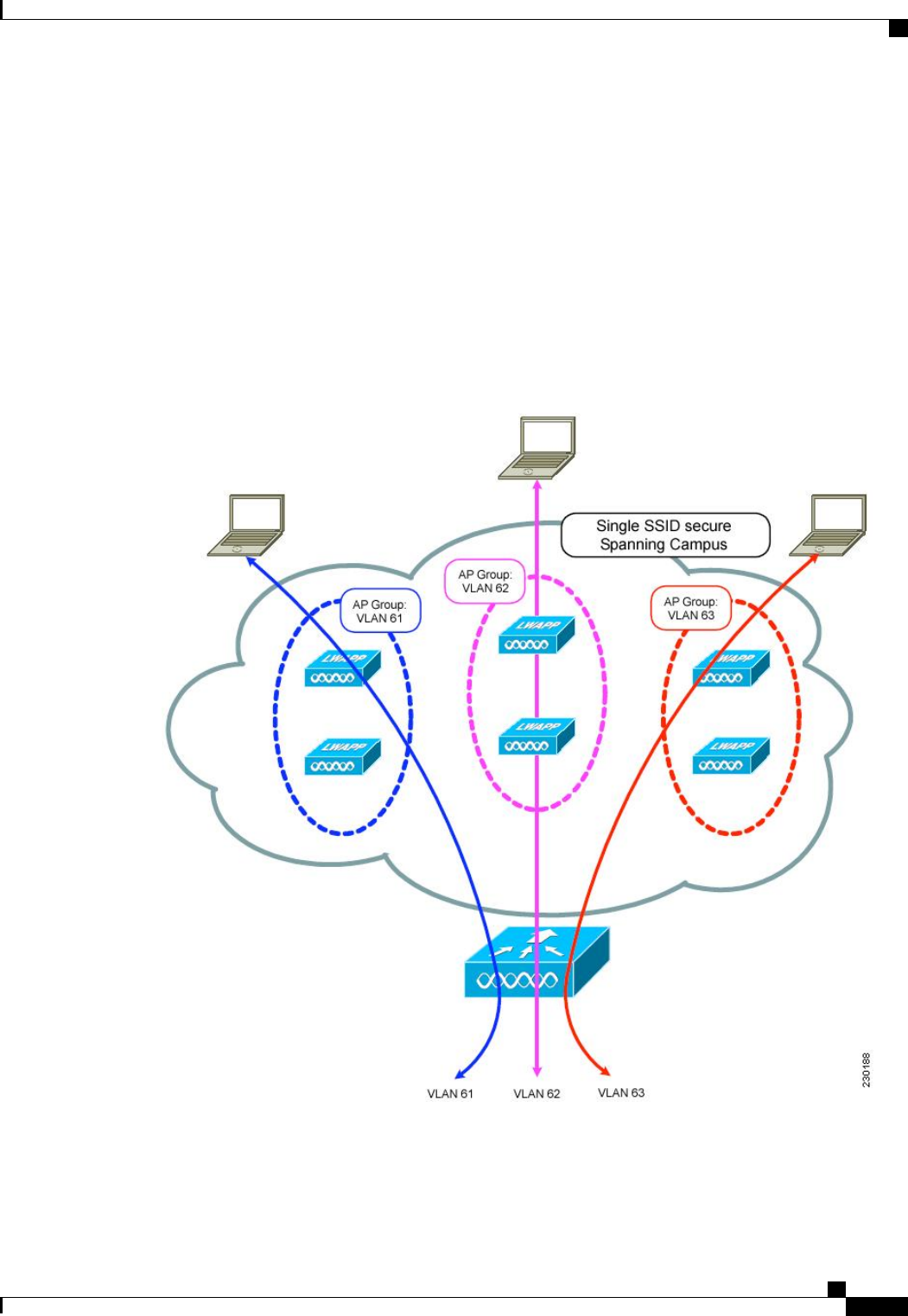
In the figure, three configured dynamic interfaces are mapped to three different VLANs (VLAN 61, VLAN
62, and VLAN 63). Three access point groups are defined, and each is a member of a different VLAN, but
all are members of the same SSID. A client within the wireless SSID is assigned an IP address from the VLAN
subnet on which its access point is a member. For example, any user that associates with an access point that
is a member of access point group VLAN 61 is assigned an IP address from that subnet.
In the figure, the controller internally treats roaming between access points as a Layer 3 roaming event. In
this way, WLAN clients maintain their original IP addresses.
After all access points have joined the controller, you can create access point groups and assign up to 16
WLANs to each group. Each access point advertises only the enabled WLANs that belong to its access point
group. The access point does not advertise disabled WLANs in its access point group or WLANs that belong
to another group.
Figure 46: Access Point Groups
Cisco Wireless LAN Controller Configuration Guide, Release 7.4
OL-28744-01 623
Information About Access Point Groups

Configuring Access Point Groups
Step 1 Configure the appropriate dynamic interfaces and map them to the desired VLANs.
For example, to implement the network described in the Information About Access Point Groups section, create dynamic
interfaces for VLANs 61, 62, and 63 on the controller. See the Configuring Dynamic Interfaces section for information
about how to configure dynamic interfaces.
Step 2 Create the access point groups. See the Creating Access Point Groups section.
Step 3 Create a RF profile. See the Creating an RF Profile section.
Step 4 Assign access points to the appropriate access point groups. See the Creating Access Point Groups section.
Step 5 Apply the RF profile on the AP groups. See the Applying RF Profile to AP Groups section.
Creating Access Point Groups (GUI)
Step 1 Choose WLANs >Advanced >AP Groups to open the AP Groups page.
This page lists all the access point groups currently created on the controller. By default, all access points belong to the
default access point group “default-group,”unless you assign them to other access point groups.
The controller creates a default access point group and automatically populates it with the first 16 WLANs
(WLANs with IDs 1 through 16, or fewer if 16 WLANs are not configured). This default group cannot be
modified (you cannot add WLANs to it nor delete WLANs from it). It is dynamically updated whenever the
first 16 WLANs are added or deleted. If an access point does not belong to an access point group, it is assigned
to the default group and uses the WLANs in that group. If an access point joins the controller with an undefined
access point group name, the access point keeps its group name but uses the WLANs in the default-group access
point group.
Note
Step 2 Click Add Group to create a new access point group. The Add New AP Group section appears at the top of the page.
Step 3 In the AP Group Name text box, enter the group’s name.
Step 4 In the Description text box, enter the group’s description.
Step 5 In the NAS-ID text box, enter the network access server identifier for the AP group.
Step 6 Click Add. The newly created access point group appears in the list of access point groups on the AP Groups page.
If you ever want to delete this group, hover your cursor over the blue drop-down arrow for the group and choose
Remove. An error message appears if you try to delete an access point group that is used by at least one access
point. Before deleting an access point group in controller software release 6.0 or later releases, move all access
points in the group to another group. The access points are not moved to the default-group access point group
as in previous releases.
Note
Cisco Wireless LAN Controller Configuration Guide, Release 7.4
624 OL-28744-01
Configuring Access Point Groups

Step 7 Click the name of the group to edit this new group. The AP Groups > Edit (General) page appears.
Step 8 Change the description of this access point group by entering the new text in the AP Group Description text box and
click Apply.
Step 9 Choose the WLANs tab to open the AP Groups > Edit (WLANs) page. This page lists the WLANs that are currently
assigned to this access point group.
Step 10 Click Add New to assign a WLAN to this access point group. The Add New section appears at the top of the page.
Step 11 From the WLAN SSID drop-down list, choose the SSID of the WLAN.
Step 12 From the Interface Name drop-down list, choose the interface to which you want to map the access point group. Choose
the quarantine VLAN if you plan to enable network admission control (NAC) out-of-band support.
The interface name in the default-group access point group matches the WLAN interface.Note
Step 13 Select the NAC State check box to enable NAC out-of-band support for this access point group. To disable NAC
out-of-band support, leave the check box unselected, which is the default value.
Step 14 Click Add to add this WLAN to the access point group. This WLAN appears in the list of WLANs that are assigned to
this access point group.
If you ever want to remove this WLAN from the access point group, hover your cursor over the blue drop-down
arrow for the WLAN and choose Remove.
Note
Step 15 Repeat Step 9 through Step 13 to add any additional WLANs to this access point group.
Step 16 Choose the APs tab to assign access points to this access point group. The AP Groups > Edit (APs) page lists the access
points that are currently assigned to this group as well as any access points that are available to be added to the group.
If an access point is not currently assigned to a group, its group name appears as “default-group”.
Step 17 Select the check box to the left of the access point name and click Add APs to add an access point to this access point
group. The access point now appears in the list of access points currently in this access point group.
To select all of the available access points at once, select the AP Name check box. All of the access points are
then selected.
Note
If you ever want to remove an access point from the group, select the check box to the left of the access point
name and click Remove APs. To select all of the access points at once, select the AP Name check box. All of
the access points are then removed from this group.
Note
If you ever want to change the access point group to which an access point belongs, choose Wireless >Access
Points >All APs >ap_name >Advanced tab, choose the name of another access point group from the AP
Group Name drop-down list, and click Apply.
Note
Step 18 In the 802.11u tab, do the following:
a) Choose a HotSpot group that groups similar HotSpot venues.
b) Choose a venue type that is based on the HotSpot venue group that you choose.
c) To add a new venue, click Add New Venue and enter the language name that is used at the venue and the venue name
that is associated with the basic service set (BSS). This name is used in cases where the SSID does not provide enough
information about the venue.
d) Select the operating class(es) for the AP group.
e) Click Apply.
Step 19 Click Save Configuration.
Cisco Wireless LAN Controller Configuration Guide, Release 7.4
OL-28744-01 625
Creating Access Point Groups (GUI)

Creating Access Point Groups (CLI)
Step 1 Create an access point group by entering this command:
config wlan apgroup add group_name
To delete an access point group, enter the config wlan apgroup delete group_name command. An error message
appears if you try to delete an access point group that is used by at least one access point. Before deleting an
access point group in controller software release 6.0 or later releases, move all access points in the group to
another group. The access points are not moved to the default-group access point group as in previous releases.
To see the access points in a group, enter the show wlan apgroups command. To move the access points to
another group, enter the config ap group-name group_name Cisco_AP command.
Note
Step 2 Add a description to an access point group by entering this command:
config wlan apgroup description group_name description
Step 3 Assign a WLAN to an access point group by entering this command:
config wlan apgroup interface-mapping add group_name wlan_id interface_name
To remove a WLAN from an access point group, enter the config wlan apgroup interface-mapping delete
group_name wlan_id command.
Note
Step 4 Enable or disable NAC out-of-band support for this access point group by entering this command:
config wlan apgroup nac {enable |disable}group_name wlan_id
Step 5 Configure a WLAN radio policy on the access point group by entering this command:
config wlan apgroup wlan-radio-policy apgroup_name wlan_id {802.11a-only |802.11bg |802.11g-only |all}
Step 6 Assign an access point to an access point group by entering this command:
config ap group-name group_name Cisco_AP
To remove an access point from an access point group, reenter this command and assign the access point to
another group.
Note
Step 7 To configure HotSpot for the AP group, enter this command:
config wlan apgroup hotspot {venue |operating-class}
Step 8 Save your changes by entering this command:
save config
Viewing Access Point Groups (CLI)
To view information about or to troubleshoot access point groups, use these commands:
•See a list of all access point groups on the controller by entering this command:
show wlan apgroups
•See the BSSIDs for each WLAN assigned to an access point group by entering this command:
show ap wlan {802.11a |802.11b}Cisco_AP
•See the number of WLANs enabled for an access point group by entering this command:
Cisco Wireless LAN Controller Configuration Guide, Release 7.4
626 OL-28744-01
Creating Access Point Groups (CLI)

show ap config {802.11a |802.11b}Cisco_AP
•Enable or disable debugging of access point groups by entering this command:
debug group {enable |disable}
Cisco Wireless LAN Controller Configuration Guide, Release 7.4
OL-28744-01 627
Viewing Access Point Groups (CLI)

Cisco Wireless LAN Controller Configuration Guide, Release 7.4
628 OL-28744-01
Viewing Access Point Groups (CLI)

CHAPTER 93
Configuring RF Profiles
•Prerequisites for Configuring RF Profiles, page 629
•Restrictions for Configuring RF Profiles, page 629
•Information About RF Profiles, page 630
•Configuring an RF Profile (GUI), page 632
•Configuring an RF Profile (CLI), page 633
•Applying an RF Profile to AP Groups (GUI), page 634
•Applying RF Profiles to AP Groups (CLI), page 635
Prerequisites for Configuring RF Profiles
Once you create an AP group and apply RF profiles or modify an existing AP group, the new settings are in
effect and the following rules become effective:
•The same RF profile must be applied and present on every controller of the AP group or the action will
fail for that controller.
•You can assign the same RF profile to more than one AP group.
Restrictions for Configuring RF Profiles
•Once you create an AP group and apply RF profiles or modify an existing AP group, the new settings
are in effect and the following rules become effective:
◦AP that has a custom power setting applied for AP power is not in global mode configuration, an
RF profile has no effect on this AP. For RF profiling to work, all APs must have their channel and
power managed by RRM.
◦Within the AP group, changing the assignment of an RF profile on either band causes the AP to
reboot.
◦Once you assign an RF profile to an AP group, you cannot make changes to that RF profile. You
must change the AP group RF profile settings to none in order to change the RF profile and then
Cisco Wireless LAN Controller Configuration Guide, Release 7.4
OL-28744-01 629

add it back to the AP group. You can also work around this restriction by disabling the network
that will be affected by the changes that you will be making either for 802.11a or 802.11b.
◦You cannot delete an AP group that has APs assigned to it.
◦You cannot delete an RF profile that is applied to an AP group.
•If you enable Out of Box, save the configuration, and then reboot the CIsco WLC, the status of Out of
Box is changed to disabled. This behavior is observed in Cisco WiSM2, Cisco 5500 Series WLC, and
Cisco 2500 Series WLC. The workaround is to enable Out of Box again after you reboot the Cisco WLC.
Information About RF Profiles
RF Profiles allows you to tune groups of APs that share a common coverage zone together and selectively
change how RRM will operates the APs within that coverage zone.
For example, a university might deploy a high density of APs in an area where a high number of users will
congregate or meet. This situation requires that you manipulate both data rates and power to address the cell
density while managing the co-channel interference. In adjacent areas, normal coverage is provided and such
manipulation would result in a loss of coverage.
Using RF profiles and AP groups allows you to optimize the RF settings for AP groups that operate in different
environments or coverage zones. RF profiles are created for the 802.11 radios. RF profiles are applied to all
APs that belong to an AP group, where all APs in that group will have the same profile settings.
The RF profile gives you the control over the data rates and power (TPC) values.
The application of an RF profile does not change the AP’s status in RRM. It is still in global configuration
mode controlled by RRM.
Note
To address high-density complex RF topologies, the following configurations are available:
•High Density Configurations—The following configurations are available to fine tune RF environments
in a dense wireless network:
•Client limit per WLAN or radio—Maximum number of clients that can communicate with the AP
in a high-density environment.
•Client trap threshold—Threshold value of the number of clients that associate with an access point,
after which an SNMP trap is sent to the controller and Cisco Prime Infrastructure.
•Stadium Vision Configurations—You can configure the following parameter:
•Multicast data rates—Configurable data rate for multicast traffic based on the RF condition of an
AP.
•Out-of-Box AP Configurations—To create an Out of Box AP group that consists of newly installed
access points that belong to the default AP group. When you enable this feature:
•Newly installed access points that are part of the default AP group will be part of the Out-of-Box
AP group and their radios will be switched off. This eliminates any RF instability caused by the
new access points.
Cisco Wireless LAN Controller Configuration Guide, Release 7.4
630 OL-28744-01
Information About RF Profiles

•All access points that do not have a group name become part of the Out of Box AP group.
•Special RF profiles are created per 802.11 band. These RF profiles have default settings for all the
existing RF parameters and additional new configurations.
When you disable this feature after you enable it, only subscription of new APs to the
Out of Box AP group stops. All APs that are subscribed to the Out of Box AP Group
remain in this AP group. The network administrators can move such APs to the default
group or a custom AP group upon network convergence.
Note
•Band Select Configurations—Band Select addresses client distribution between the 2.4-GHz and 5-GHz
bands by first understanding the client capabilities to verify whether a client can associate on both
2.4-GHz and 5-GHz spectrum. Enabling band select on a WLAN forces the AP to do probe suppression
on the 2.4-GHz band that ultimately moves dual band clients to 5-GHz spectrum. You can configure
the following band select parameters per AP Group:
•Probe response—Probe responses to clients that you can enable or disable.
•Probe Cycle Count—Probe cycle count for the RF profile. The cycle count sets the number of
suppression cycles for a new client.
•Cycle Threshold—Time threshold for a new scanning RF Profile band select cycle period. This
setting determines the time threshold during which new probe requests from a client come in a
new scanning cycle.
•Suppression Expire—Expiration time for pruning previously known 802.11b/g clients. After this
time elapses, clients become new and are subject to probe response suppression.
•Dual Band Expire—Expiration time for pruning previously known dual-band clients. After this
time elapses, clients become new and are subject to probe response suppression.
•Client RSSI—Minimum RSSI for a client to respond to a probe.
•Load Balancing Configurations—Load balancing maintains fair distribution of clients across APs. You
can configure the following parameters:
•Window—Load balancing sets client association limits by enforcing a client window size. For
example, if the window size is defined as 3, assuming fair client distribution across the floor area,
then an AP should have no more than 3 clients associated with it than the group average.
•Denial—The denial count sets the maximum number of association denials during load balancing.
•Coverage Hole Mitigation Configurations—You can configure the following parameters:
•Data RSSI—Minimum receive signal strength indication (RSSI) value for data packets received
by the access point. The value that you enter is used to identify coverage holes (or areas of poor
coverage) within your network.
•Voice RSSI—Minimum receive signal strength indication (RSSI) value for voice packets received
by the access point.
•Coverage Exception—Minimum number of clients on an access point with an RSSI value at or
below the data or voice RSSI threshold to trigger a coverage hole exception.
Cisco Wireless LAN Controller Configuration Guide, Release 7.4
OL-28744-01 631
Information About RF Profiles

•Coverage Level—Percentage of clients on an access point that are experiencing a low signal level
but cannot roam to another access point. If an access point has more number of such clients than
the configured coverage level it triggers a coverage hole event.
Configuring an RF Profile (GUI)
Step 1 Choose Wireless >RF Profiles to open the RF profiles page.
Step 2 To configure the out-of-box status for all RF profiles, select or unselect the Enable Out Of Box check box.
Step 3 Click New.
Step 4 Enter the RF Profile Name and choose the radio band.
Step 5 Click Apply to configure the customizations of power and data rate parameters.
Step 6 In the General tab, enter the description for the RF profile in the Description text box.
Step 7 In the 802.11 tab, configure the data rates to be applied to the APs of this profile.
Step 8 In the RRM tab, do the following:
a) In the TPC area, configure the Maximum and Minimum Power Level Assignment, that is the maximum and minimum
power that the APs in this RF profile are allowed to use.
b) In the TPC area, configure a custom TPC power threshold for either Version1 or Version 2 of TPC.
Only one version of TPC can be operable for RRM on a given controller Version 1 and Version 2 are not
interoperable within the same RF profile. If you select a threshold value for TPCv2 and it is not in the chosen
TPC algorithm for the RF profile, this value will be ignored.
Note
c) In the Coverage Hole Detection area, configure the voice and data RSSI.
d) In the Coverage Exception text box, enter the number for clients.
e) In the Coverage Level text box, enter the percentage.
Step 9 In the High Density tab, do the following:
a) In the High Density Parameters area, enter the maximum number of clients to be allowed per AP radio and the client
trap threshold value.
b) In the Multicast Parameters area, choose the data rates from the Multicast Data Rates drop-down list.
Step 10 In the Client Distribution tab, do the following:
a) In the Load Balancing area, enter the client window size and the denial count.
The window size becomes part of the algorithm that determines whether an access point is too heavily loaded to
accept more client associations:
load-balancing window + client associations on AP with the lightest load = load-balancing threshold
In the group of access points accessible to a client device, each access point has a different number of client associations.
The access point with the lowest number of clients has the lightest load. The client window size plus the number of
clients on the access point with the lightest load forms the threshold. Access points with more client associations
than this threshold is considered busy, and clients can associate only to access points with client counts lower than
the threshold.
The denial count sets the maximum number of association denials during load balancing.
b) In the Band Select area, select or unselect the Probe Response check box.
The Band Select configurations are available only for the 802.11b/g RF profiles.Note
Cisco Wireless LAN Controller Configuration Guide, Release 7.4
632 OL-28744-01
Configuring an RF Profile (GUI)

c) In the Cycle Count text box, enter a value that sets the number of suppression cycles for a new client. The default
count is 2.
d) In the Cycle Threshold text box, enter a time period in milliseconds that determines the time threshold during which
new probe requests from a client from a new scanning cycle. The default cycle threshold is 200 milliseconds.
e) In the Suppression Expire text box, enter a time period after which the 802.11 b/g clients become new and are subject
to probe response suppression.
f) In the Dual Band Expire text box, enter a time period after which the dual band clients become new and are subject
to probe response suppression.
g) In the Client RSSI text box, enter the minimum RSSI for a client to respond to a probe.
Step 11 Click Apply to commit your changes.
Step 12 Click Save Configuration to save your changes.
Configuring an RF Profile (CLI)
Step 1 To configure the out-of-box status for all RF profiles, enter this command:
config rf-profile out-of-box {enable |disable}
Step 2 To create or delete an RF profile, enter this command:
config rf-profile {create {802.11a |802.11b} | delete}profile-name
Step 3 To specify a description for the RF profile, enter this command:
config rf-profile description text profile-name
Step 4 To configure the data rates to be applied to the APs of this profile, enter this command:
config rf-profile data-rates {802.11a |802.11b} {disabled |mandatory |supported}rate profile-name
Step 5 To configure the maximum and minimum power level assignment, that is the maximum and minimum power that the
APs in this RF profile are allowed to use, enter this command:
config rf-profile {tx-power-max |tx-power-min}power-value profile-name
Step 6 To configure a custom TPC power threshold for either Version1 or Version 2 of TPC, enter this command:
config rf-profile {tx-power-control-thresh-v1 |tx-power-control-thresh-v2}power-threshold profile-name
Step 7 To configure the coverage hole detection parameters:
a) To configure the coverage data, enter this command:
config rf-profile coverage data value-in-dBm profile-name
b) To configure the minimum client coverage exception level, enter this command:
config rf-profile coverage exception clients profile-name
c) To configure the coverage exception level percentage, enter this command:
config rf-profile coverage level percentage-value profile-name
d) To configure the coverage of voice, enter this command:
config rf-profile coverage voice value-in-dBm profile-name
Cisco Wireless LAN Controller Configuration Guide, Release 7.4
OL-28744-01 633
Configuring an RF Profile (CLI)

Step 8 To configure the maximum number of clients to be allowed per AP radio, enter this command:
config rf-profile max-clients num-of-clients profile-name
Step 9 To configure the client trap threshold value, enter this command:
config rf-profile client-trap-threshold threshold-value profile-name
Step 10 To configure multicast, enter this command:
config rf-profile multicast data-rate rate profile-name
Step 11 To configure load balancing, enter this command:
config rf-profile load-balancing {window num-of-clients |denial value}profile-name
Step 12 To configure band select:
a) To configure the band select cycle count, enter this command:
config rf-profile band-select cycle-count max-num-of-cycles profile-name
b) To configure the cycle threshold, enter this command:
config rf-profile band-select cycle-threshold time-in-milliseconds profile-name
c) To configure the expiry of the band select, enter this command:
config rf-profile band-select expire {dual-band |suppression}time-in-seconds profile-name
d) To configure the probe response, enter this command:
config rf-profile band-select probe-response {enable |disable}profile-name
e) To configure the minimum RSSI for a client to respond to a probe, enter this command:
config rf-profile band-select client-rssi value-in-dBm profile-name
Step 13 Configure the 802.11n only mode for an access point group base by entering this command:
config rf-profile 11n-client-only {enable |disable}rf-profile-name
In the 802.11n only mode, the access point broadcasts support for 802.11n speeds. Only 802.11n clients are allowed to
associate with the access point
Applying an RF Profile to AP Groups (GUI)
Step 1 Choose WLANs >Advanced >AP Groups to open the AP Groups page.
Step 2 Click the AP Group Name to open the AP Group > Edit page.
Step 3 Click the RF Profile tab to configure the RF profile details. You can choose an RF profile for each band (802.11a/802.11b)
or you can choose just one or none to apply to this group.
Until you choose the APs and add them to the new group, no configurations are applied. You can save the new
configuration as is, but no profiles are applied. Once you choose the APs to move the AP group, the process of
moving the APs into the new group reboots the APs and the configurations for the RF profiles are applied to
the APs in that AP group.
Note
Step 4 Click the APs tab and choose the APs to add to the AP group.
Step 5 Click Add APs to add the selected APs to the AP group. A warning message displays that the AP group will reboot the
APs will rejoin the controller.
Cisco Wireless LAN Controller Configuration Guide, Release 7.4
634 OL-28744-01
Applying an RF Profile to AP Groups (GUI)

APs cannot belong to two AP groups at
once.
Note
Step 6 Click Apply. The APs are added to the AP Group.
Applying RF Profiles to AP Groups (CLI)
What to Do Next
Use this command to apply RF profiles to AP groups:
•config wlan apgroup profile-mapping {add |delete}ap-group-name rf-profile-name
Cisco Wireless LAN Controller Configuration Guide, Release 7.4
OL-28744-01 635
Applying RF Profiles to AP Groups (CLI)

Cisco Wireless LAN Controller Configuration Guide, Release 7.4
636 OL-28744-01
Applying RF Profiles to AP Groups (CLI)

CHAPTER 94
Configuring Web Redirect with 8021.X
Authentication
•Information About Web Redirect with 802.1X Authentication, page 637
•Configuring the RADIUS Server (GUI), page 638
•Configuring Web Redirect, page 639
•Disabling Accounting Servers per WLAN (GUI), page 640
•Disabling Coverage Hole Detection per WLAN, page 640
Information About Web Redirect with 802.1X Authentication
You can configure a WLAN to redirect a user to a particular web page after 802.1X authentication has
completed successfully. You can configure the web redirect to give the user partial or full access to the network.
Conditional Web Redirect
If you enable conditional web redirect, the user can be conditionally redirected to a particular web page after
802.1X authentication has completed successfully. You can specify the redirect page and the conditions under
which the redirect occurs on your RADIUS server. Conditions might include the user’s password reaching
expiration or the user needing to pay his or her bill for continued usage.
If the RADIUS server returns the Cisco AV-pair “url-redirect,”then the user is redirected to the specified URL
upon opening a browser. If the server also returns the Cisco AV-pair “url-redirect-acl,”the specified access
control list (ACL) is installed as a preauthentication ACL for this client. The client is not considered fully
authorized at this point and can only pass traffic allowed by the preauthentication ACL.
After the client completes a particular operation at the specified URL (for example, changing a password or
paying a bill), the client must reauthenticate. When the RADIUS server does not return a “url-redirect,”the
client is considered fully authorized and allowed to pass traffic.
Cisco Wireless LAN Controller Configuration Guide, Release 7.4
OL-28744-01 637

The conditional web redirect feature is available only for WLANs that are configured for 802.1X or
WPA+WPA2 Layer 2 security.
Note
After you configure the RADIUS server, you can then configure the conditional web redirect on the controller
using either the controller GUI or CLI.
Splash Page Web Redirect
If you enable splash page web redirect, the user is redirected to a particular web page after 802.1X authentication
has completed successfully. After the redirect, the user has full access to the network. You can specify the
redirect page on your RADIUS server. If the RADIUS server returns the Cisco AV-pair “url-redirect,”then
the user is redirected to the specified URL upon opening a browser. The client is considered fully authorized
at this point and is allowed to pass traffic, even if the RADIUS server does not return a “url-redirect.”
The splash page web redirect feature is available only for WLANs that are configured for 802.1X or
WPA+WPA2 Layer 2 security with 802.1x key management. Preshared key management is not supported
with any Layer 2 security method.
Note
Suppose there are backend applications running on the wireless clients and they use HTTP or HTTPS port
for their communication. If the applications start communicating before the actual web page is opened, the
redirect functionality does not work with web passthrough.
After you configure the RADIUS server, you can then configure the splash page web redirect on the controller
using either the controller GUI or CLI.
Configuring the RADIUS Server (GUI)
These instructions are specific to the CiscoSecure ACS; however, they should be similar to those for other
RADIUS servers.
Note
Step 1 From the CiscoSecure ACS main menu, choose Group Setup.
Step 2 Click Edit Settings.
Step 3 From the Jump To drop-down list, choose RADIUS (Cisco IOS/PIX 6.0).
Step 4 Select the [009\001] cisco-av-pair check box.
Step 5 Enter the following Cisco AV-pairs in the [009\001] cisco-av-pair edit box to specify the URL to which the user is
redirected and, if configuring conditional web redirect, the conditions under which the redirect takes place, respectively:
url-redirect=http://url
url-redirect-acl=acl_name
Cisco Wireless LAN Controller Configuration Guide, Release 7.4
638 OL-28744-01
Configuring the RADIUS Server (GUI)