Cisco Systems 102087P Cisco Aironet 802.11ac Dual Band Access Points User Manual Wireless LAN Controller Configuration Guide Part3
Cisco Systems Inc Cisco Aironet 802.11ac Dual Band Access Points Wireless LAN Controller Configuration Guide Part3
Contents
- 1. Manual
- 2. revised manual
- 3. Wireless LAN Controller Configuration Guide_Part1
- 4. Wireless LAN Controller Configuration Guide_Part2
- 5. Wireless LAN Controller Configuration Guide_Part3
- 6. Wireless LAN Controller Configuration Guide_Part4
Wireless LAN Controller Configuration Guide_Part3

Configuring Web Redirect
Configuring Web Redirect (GUI)
Step 1 Choose WLANs to open the WLANs page.
Step 2 Click the ID number of the desired WLAN. The WLANs > Edit page appears.
Step 3 Choose the Security and Layer 2 tabs to open the WLANs > Edit (Security > Layer 2) page.
Step 4 From the Layer 2 Security drop-down list, choose 802.1X or WPA+WPA2.
Step 5 Set any additional parameters for 802.1X or WPA+WPA2.
Step 6 Choose the Layer 3 tab to open the WLANs > Edit (Security > Layer 3) page.
Step 7 From the Layer 3 Security drop-down list, choose None.
Step 8 Check the Web Policy check box.
Step 9 Choose one of the following options to enable conditional or splash page web redirect: Conditional Web Redirect or
Splash Page Web Redirect. The default value is disabled for both parameters.
Step 10 If the user is to be redirected to a site external to the controller, choose the ACL that was configured on your RADIUS
server from the Preauthentication ACL drop-down list.
Step 11 Click Apply to commit your changes.
Step 12 Click Save Configuration to save your changes.
Configuring Web Redirect (CLI)
Step 1 Enable or disable conditional web redirect by entering this command:
config wlan security cond-web-redir {enable |disable}wlan_id
Step 2 Enable or disable splash page web redirect by entering this command:
config wlan security splash-page-web-redir {enable |disable}wlan_id
Step 3 Save your settings by entering this command:
save config
Step 4 See the status of the web redirect features for a particular WLAN by entering this command:
show wlan wlan_id
Information similar to the following appears:
WLAN Identifier.................................. 1
Profile Name..................................... test
Network Name (SSID).............................. test
...
Web Based Authentication......................... Disabled
Cisco Wireless LAN Controller Configuration Guide, Release 7.4
OL-28744-01 639
Configuring Web Redirect

Web-Passthrough.................................. Disabled
Conditional Web Redirect......................... Disabled
Splash-Page Web Redirect......................... Enabled
...
Disabling Accounting Servers per WLAN (GUI)
Disabling accounting servers disables all accounting operations and prevents the controller from falling
back to the default RADIUS server for the WLAN.
Note
Step 1 Choose WLANs to open the WLANs page.
Step 2 Click the ID number of the WLAN to be modified. The WLANs > Edit page appears.
Step 3 Choose the Security and AAA Servers tabs to open the WLANs > Edit (Security > AAA Servers) page.
Step 4 Unselect the Enabled check box for the Accounting Servers.
Step 5 Click Apply to commit your changes.
Step 6 Click Save Configuration to save your changes.
Disabling Coverage Hole Detection per WLAN
Coverage hole detection is enabled globally on the controller.Note
You can disable coverage hole detection on a per-WLAN basis. When you disable coverage hole detection
on a WLAN, a coverage hole alert is still sent to the controller, but no other processing is done to mitigate
the coverage hole. This feature is useful for guest WLANs where guests are connected to your network
for short periods of time and are likely to be highly mobile.
Note
Cisco Wireless LAN Controller Configuration Guide, Release 7.4
640 OL-28744-01
Disabling Accounting Servers per WLAN (GUI)

Disabling Coverage Hole Detection on a WLAN (GUI)
Step 1 Choose WLANs to open the WLANs page.
Step 2 Click the profile name of the WLAN to be modified. The WLANs > Edit page appears.
Step 3 Choose the Advanced tab to display the WLANs > Edit (Advanced) page.
Step 4 Unselect the Coverage Hole Detection Enabled check box.
OEAP 600 Series Access Points do not support coverage hole
detection.
Note
Step 5 Click Apply.
Step 6 Click Save Configuration.
Disabling Coverage Hole Detection on a WLAN (CLI)
Step 1 Disable coverage hole detection on a by entering this command:
config wlan chd wlan-id disable
OEAP 600 Series Access Points do not support Coverage Hole
detection.
Note
Step 2 Save your settings by entering this command:
save config
Step 3 See the coverage hole detection status for a particular WLAN by entering this command:
show wlan wlan-id
Information similar to the following appears:
WLAN Identifier.................................. 2
Profile Name..................................... wlan2
Network Name (SSID).............................. 2
...
CHD per WLAN.................................. Disabled
Cisco Wireless LAN Controller Configuration Guide, Release 7.4
OL-28744-01 641
Disabling Coverage Hole Detection per WLAN

Cisco Wireless LAN Controller Configuration Guide, Release 7.4
642 OL-28744-01
Disabling Coverage Hole Detection per WLAN

CHAPTER 95
Configuring NAC Out-of-Band Integration
•Prerequisites for NAC Out Of Band, page 643
•Restrictions for NAC Out of Band, page 644
•Information About NAC Out-of-Band Integration, page 645
•Configuring NAC Out-of-Band Integration (GUI), page 645
•Configuring NAC Out-of-Band Integration (CLI), page 647
Prerequisites for NAC Out Of Band
•CCA software release 4.5 or later releases is required for NAC out-of-band integration.
•Because the NAC appliance supports static VLAN mapping, you must configure a unique quarantine
VLAN for each interface that is configured on the controller. For example, you might configure a
quarantine VLAN of 110 on controller 1 and a quarantine VLAN of 120 on controller 2. However, if
two WLANs or guest LANs use the same distribution system interface, they must use the same quarantine
VLAN if they have one NAC appliance deployed in the network. The NAC appliance supports unique
quarantine-to-access VLAN mapping.
•For a posture reassessment that is based on a session expiry, you must configure the session timeout on
both the NAC appliance and the WLAN, making sure that the session expiry on the WLAN is greater
than that on the NAC appliance.
•When a session timeout is configured on an open WLAN, the timing out of clients in the Quarantine
state is determined by the timer on the NAC appliance. After the session timeout expires for WLANs
that use web authentication, clients deauthenticate from the controller and must perform posture validation
again.
•All Layer 2 and Layer 3 authentication occurs in the quarantine VLAN. To use external web
authentication, you must configure the NAC appliance to allow HTTP traffic to and from external web
servers and to allow the redirect URL in the quarantine VLAN.
Cisco Wireless LAN Controller Configuration Guide, Release 7.4
OL-28744-01 643

See the Cisco NAC appliance configuration guides for configuration instructions: http:/
/www.cisco.com/en/US/products/ps6128/products_installation_and_configuration_
guides_list.html.
Note
•If you want to enable NAC on an access point group VLAN, you must first enable NAC on the WLAN.
Then you can enable or disable NAC on the access point group VLAN. If you ever decide to disable
NAC on the WLAN, be sure to disable it on the access point group VLAN as well.
•The NAC appliance supports up to 3500 users, and the controller supports up to 5000 users. Multiple
NAC appliances might need to be deployed.
•In controller software releases prior to 5.1, the controller integrates with the NAC appliance only in
in-band mode, where the NAC appliance must remain in the data path. For in-band mode, a NAC
appliance is required at each authentication location (such as at each branch or for each controller), and
all traffic must traverse the NAC enforcement point. In controller software release 5.1 or later releases,
the controller can integrate with the NAC appliance in out-of-band mode, where the NAC appliance
remains in the data path only until clients have been analyzed and cleaned. Out-of-band mode reduces
the traffic load on the NAC appliance and enables centralized NAC processing.
•NAC out-of-band integration is supported only on WLANs configured for FlexConnect central switching.
It is not supported for use on WLANs configured for FlexConnect local switching.
Restrictions for NAC Out of Band
•Network Admission Control (NAC) is supported on 10 percent of the total number of wireless clients
supported on the controller.
•NAC out-of-band integration is not supported for use with the WLAN AAA override feature.
•In controller software releases prior to 5.1, the controller integrates with the NAC appliance only in
in-band mode, where the NAC appliance must remain in the data path. For in-band mode, a NAC
appliance is required at each authentication location (such as at each branch or for each controller), and
all traffic must traverse the NAC enforcement point. In controller software release 5.1 or later releases,
the controller can integrate with the NAC appliance in out-of-band mode, where the NAC appliance
remains in the data path only until clients have been analyzed and cleaned. Out-of-band mode reduces
the traffic load on the NAC appliance and enables centralized NAC processing.
•NAC out-of-band integration is supported only on WLANs configured for FlexConnect central switching.
It is not supported for use on WLANs configured for FlexConnect local switching.
Cisco Wireless LAN Controller Configuration Guide, Release 7.4
644 OL-28744-01
Restrictions for NAC Out of Band
Information About NAC Out-of-Band Integration
The Cisco NAC Appliance, also known as Cisco Clean Access (CCA), is a network admission control (NAC)
product that enables network administrators to authenticate, authorize, evaluate, and remediate wired, wireless,
and remote users and their machines prior to allowing users onto the network. NAC identifies whether machines
are compliant with security policies and repairs vulnerabilities before permitting access to the network.
The NAC appliance is available in two modes: in-band and out-of-band. Customers can deploy both modes
if desired, each geared toward certain types of access (in-band for supporting wireless users and out-of-band
for supporting wired users, for example).
To implement the NAC out-of-band feature on the controller, you must enable NAC support on the WLAN
or guest LAN and then map this WLAN or guest LAN to an interface that is configured with a quarantine
VLAN (untrusted VLAN) and an access VLAN (trusted VLAN). When a client associates and completes
Layer 2 authentication, the client obtains an IP address from the access VLAN subnet, but the client state is
Quarantine. While deploying the NAC out-of-band feature, be sure that the quarantine VLAN is allowed only
between the Layer 2 switch on which the controller is connected and the NAC appliance and that the NAC
appliance is configured with a unique quarantine-to-access VLAN mapping. Client traffic passes into the
quarantine VLAN, which is trunked to the NAC appliance. After posture validation is completed, the client
is prompted to take remedial action. After cleaning is completed, the NAC appliance updates the controller
to change the client state from Quarantine to Access.
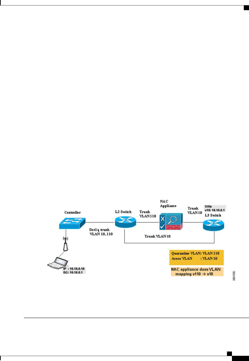
The link between the controller and the switch is configured as a trunk, enabling the quarantine VLAN (110)
and the access VLAN (10). On the Layer 2 switch, the quarantine traffic is trunked to the NAC appliance
while the access VLAN traffic goes directly to the Layer 3 switch. Traffic that reaches the quarantine VLAN
on the NAC appliance is mapped to the access VLAN based on a static mapping configuration.
Figure 47: Example of NAC Out-of-Band Integration
Configuring NAC Out-of-Band Integration (GUI)
Step 1 Configure the quarantine VLAN for a dynamic interface as follows:
Cisco Wireless LAN Controller Configuration Guide, Release 7.4
OL-28744-01 645
Information About NAC Out-of-Band Integration

a) Choose Controller >Interfaces to open the Interfaces page.
b) Click New to create a new dynamic interface.
c) In the Interface Name text box, enter a name for this interface, such as “quarantine.”
d) In the VLAN ID text box, enter a nonzero value for the access VLAN ID, such as “10.”
e) Click Apply to commit your changes. The Interfaces > Edit page appears.
f) Select the Quarantine check box and enter a nonzero value for the quarantine VLAN ID, such as “110.”
We recommend that you configure unique quarantine VLANs throughout your network. If multiple controllers
are configured in the same mobility group and access interfaces on all controllers are in the same subnet, it
is mandatory to have the same quarantine VLAN if there is only one NAC appliance in the network. If
multiple controllers are configured in the same mobility group and access interfaces on all controllers are
in different subnets, it is mandatory to have different quarantine VLANs if there is only one NAC appliance
in the network.
Note
g) Configure any remaining text boxes for this interface, such as the IP address, netmask, and default gateway.
h) Click Apply to save your changes.
Step 2 Configure NAC out-of-band support on a WLAN or guest LAN as follows:
a) Choose WLANs to open the WLANs page.
b) Click the ID number of the desired WLAN or guest LAN. The WLANs > Edit page appears.
c) Choose the Advanced tab to open the WLANs > Edit (Advanced) page.
d) Configure NAC out-of-band support for this WLAN or guest LAN by selecting the NAC State check box. To disable
NAC out-of-band support, leave the check box unselected, which is the default value.
e) Click Apply to commit your changes.
Step 3 Configure NAC out-of-band support for a specific access point group as follows:
a) Choose WLANs >Advanced >AP Groups to open the AP Groups page.
b) Click the name of the desired access point group.
c) Choose the WLANs tab to open the AP Groups > Edit (WLANs) page.
d) Click Add New to assign a WLAN to this access point group. The Add New section appears at the top of the page.
e) From the WLAN SSID drop-down list, choose the SSID of the WLAN.
f) From the Interface Name drop-down list, choose the interface to which you want to map the access point group.
Choose the quarantine VLAN if you plan to enable NAC out-of-band support.
g) To enable NAC out-of-band support for this access point group, select the NAC State check box. To disable NAC
out-of-band support, leave the check box unselected, which is the default value.
h) Click Add to add this WLAN to the access point group. This WLAN appears in the list of WLANs assigned to this
access point group.
If you ever want to remove this WLAN from the access point group, hover your cursor over the blue
drop-down arrow for the WLAN and choose Remove.
Note
Step 4 Click Save Configuration to save your changes.
Step 5 See the current state of the client (Quarantine or Access) as follows:
a) Choose Monitor >Clients to open the Clients page.
b) Click the MAC address of the desired client to open the Clients > Detail page. The NAC state appears under the
Security Information section.
The client state appears as “Invalid”if the client is probing, has not yet associated to a WLAN, or cannot
complete Layer 2 authentication.
Note
Cisco Wireless LAN Controller Configuration Guide, Release 7.4
646 OL-28744-01
Configuring NAC Out-of-Band Integration (GUI)

Configuring NAC Out-of-Band Integration (CLI)
Step 1 Configure the quarantine VLAN for a dynamic interface by entering this command:
config interface quarantine vlan interface_name vlan_id
You must configure a unique quarantine VLAN for each interface on the controller.Note
To disable the quarantine VLAN on an interface, enter 0for the VLAN ID.
Step 2 Enable or disable NAC out-of-band support for a WLAN or guest LAN by entering this command:
config {wlan |guest-lan}nac {enable |disable} {wlan_id |guest_lan_id}
Step 3 Enable or disable NAC out-of-band support for a specific access point group by entering this command:
config wlan apgroup nac {enable |disable}group_name wlan_id
Step 4 Save your changes by entering this command:
save config
Step 5 See the configuration of a WLAN or guest LAN, including the NAC state by entering this command:
show {wlan wlan_ id |guest-lan guest_lan_id}
Information similar to the following appears:
WLAN Identifier.................................. 1
Profile Name..................................... wlan
Network Name (SSID).............................. wlan
Status........................................... Disabled
MAC Filtering.................................... Disabled
Broadcast SSID................................... Enabled
AAA Policy Override.............................. Disabled
Network Admission Control
NAC-State...................................... Enabled
Quarantine VLAN............................. 110
...
Step 6 See the current state of the client (either Quarantine or Access) by entering this command:
show client detailed client_mac
Information similar to the following appears:
Client’s NAC state.................................. QUARANTINE
The client state appears as “Invalid”if the client is probing, has not yet associated to a WLAN, or cannot complete
Layer 2 authentication.
Note
Cisco Wireless LAN Controller Configuration Guide, Release 7.4
OL-28744-01 647
Configuring NAC Out-of-Band Integration (CLI)

Cisco Wireless LAN Controller Configuration Guide, Release 7.4
648 OL-28744-01
Configuring NAC Out-of-Band Integration (CLI)

CHAPTER 96
Configuring Passive Clients
•Restrictions for Passive Clients, page 649
•Information About Passive Clients, page 649
•Configuring Passive Clients (GUI), page 650
•Configuring Passive Clients (CLI), page 651
Restrictions for Passive Clients
•The passive client feature is not supported with the AP groups and FlexConnect centrally switched
WLANs.
Information About Passive Clients
Passive clients are wireless devices, such as scales and printers that are configured with a static IP address.
These clients do not transmit any IP information such as IP address, subnet mask, and gateway information
when they associate with an access point. As a result, when passive clients are used, the controller never
knows the IP address unless they use the DHCP.
Wireless LAN controllers currently act as a proxy for ARP requests. Upon receiving an ARP request, the
controller responds with an ARP response instead of passing the request directly to the client. This scenario
has two advantages:
•The upstream device that sends out the ARP request to the client will not know where the client is
located.
•Power for battery-operated devices such as mobile phones and printers is preserved because they do not
have to respond to every ARP requests.
Since the wireless controller does not have any IP related information about passive clients, it cannot respond
to any ARP requests. The current behavior does not allow the transfer of ARP requests to passive clients. Any
application that tries to access a passive client will fail.
Cisco Wireless LAN Controller Configuration Guide, Release 7.4
OL-28744-01 649

The passive client feature enables the ARP requests and responses to be exchanged between wired and wireless
clients. This feature when enabled, allows the controller to pass ARP requests from wired to wireless clients
until the desired wireless client gets to the RUN state.
Configuring Passive Clients (GUI)
Before You Begin
To configure passive clients, you must enable multicast-multicast or multicast-unicast mode.
Step 1 Choose Controller >General to open the General page.
Step 2 Choose one of the following options from the AP Multicast Mode drop-down list:
•Unicast—Configures the controller to use the unicast method to send multicast packets. This is the default value.
•Multicast—Configures the controller to use the multicast method to send multicast packets to a CAPWAP multicast
group.
Step 3 From the AP Multicast Mode drop-down list, chooseMulticast. The Multicast Group Address text box is displayed.
Step 4 In the Multicast Group Address text box, enter the IP address of the multicast group.
Step 5 Click Apply.
Step 6 Enable global multicast mode as follows:
a) Choose Controller >Multicast.
b) Select the Enable Global Multicast Mode check box.
Enabling the Multicast-Multicast Mode (GUI)
Before You Begin
To configure passive clients, you must enable multicast-multicast or multicast-unicast mode.
Step 1 Choose Controller >General to open the General page.
Step 2 Choose one of the following options from the AP Multicast Mode drop-down list:
•Unicast—Configures the controller to use the unicast method to send multicast packets. This is the default value.
•Multicast—Configures the controller to use the multicast method to send multicast packets to a CAPWAP multicast
group.
Step 3 From the AP Multicast Mode drop-down list, choose Multicast. The Multicast Group Address text box is displayed.
It is not possible to configure the AP multicast mode for Cisco Flex 7500 Series controllers because only unicast
is supported.
Note
Cisco Wireless LAN Controller Configuration Guide, Release 7.4
650 OL-28744-01
Configuring Passive Clients (GUI)

Step 4 In the Multicast Group Address text box, enter the IP address of the multicast group.
Step 5 Click Apply.
Step 6 Enable global multicast mode as follows:
a) Choose Controller >Multicast.
b) Select the Enable Global Multicast Mode check box.
Enabling the Global Multicast Mode on Controllers (GUI)
Step 1 Choose Controller >Multicast to open the Multicast page.
The Enable IGMP Snooping text box is highlighted only when you enable the Enable Global Multicast mode.
The IGMP Timeout (seconds) text box is highlighted only when you enable the Enable IGMP Snooping text
box.
Note
Step 2 Select the Enable Global Multicast Mode check box to enable the multicast mode. This step configures the controller
to use the multicast method to send multicast packets to a CAPWAP multicast group.
It is not possible to configure Global Multicast Mode for Cisco Flex 7500 Series Controllers.Note
Step 3 Select the Enable IGMP Snooping check box to enable the IGMP snooping. The default value is disabled.
Step 4 In the IGMP Timeout text box to set the IGMP timeout, enter a value between 30 and 7200 seconds.
Step 5 Click Apply to commit your changes.
Enabling the Passive Client Feature on the Controller (GUI)
Step 1 Choose WLANs >WLANs >WLAN ID to open the WLANs > Edit page. By default, the General tab is displayed.
Step 2 Choose the Advanced tab.
Step 3 Select the Passive Client check box to enable the passive client feature.
Step 4 Click Apply to commit your changes.
Configuring Passive Clients (CLI)
Step 1 Enable multicasting on the controller by entering this command:
config network multicast global enable
Cisco Wireless LAN Controller Configuration Guide, Release 7.4
OL-28744-01 651
Configuring Passive Clients (CLI)

The default value is disabled.
Step 2 Configure the controller to use multicast to send multicast to an access point by entering this command:
config network multicast mode multicast multicast_group_IP_address
Step 3 Configure passive client on a wireless LAN by entering this command:
config wlan passive-client {enable |disable}wlan_id
Step 4 Configure a WLAN by entering this command:
config wlan
Step 5 Save your changes by entering this command:
save config
Step 6 Display the passive client information on a particular WLAN by entering this command:
show wlan 2
Step 7 Verify if the passive client is associated correctly with the AP and if the passive client has moved into the DHCP required
state at the controller by entering this command:
debug client mac_address
Step 8 Display the detailed information for a client by entering this command:
show client detail mac_address
Step 9 Check if the client moves into the run state, when a wired client tries to contact the client by entering this command:
debug client mac_address
Step 10 Configure and check if the ARP request is forwarded from the wired side to the wireless side by entering this command:
debug arp all enable
Cisco Wireless LAN Controller Configuration Guide, Release 7.4
652 OL-28744-01
Configuring Passive Clients (CLI)

CHAPTER 97
Configuring Client Profiling
•Prerequisites for Configuring Client Profiling, page 653
•Restrictions for Configuring Client Profiling, page 653
•Information About Client Profiling, page 654
•Configuring Client Profiling (GUI), page 654
•Configuring Client Profiling (CLI), page 654
Prerequisites for Configuring Client Profiling
•By default, client profiling will be disabled on all WLANs.
•Client profiling is supported on access points that are in Local mode and FlexConnect mode.
•Both DHCP Proxy and DHCP Bridging mode on the controller are supported.
•Accounting Server configuration on the WLAN must be pointing at an ISE running 1.1 MnR or later
releases. Cisco ACS does not support client profiling.
•The type of DHCP server used does not affect client profiling.
•If the DHCP_REQUEST packet contains a string that is found in the Profiled Devices list of the ISE,
then the client will be profiled automatically.
•The client is identified based on the MAC address sent in the Accounting request packet.
•Only a MAC address should be sent as calling station ID in accounting packets when profiling is enabled.
•To enable client profiling, you must enable the DHCP required flag and disable the local authentication
flag.
Restrictions for Configuring Client Profiling
•Profiling is not supported for clients in the following scenarios:
•Clients associating with FlexConnect mode APs in Standalone mode.
Cisco Wireless LAN Controller Configuration Guide, Release 7.4
OL-28744-01 653

•Clients associating with FlexConnect mode APs when local authentication is done with local
switching is enabled.
•With profiling enabled for local switching FlexConnect mode APs, only VLAN override is supported
as an AAA override attribute.
•While the controller parses the DHCP profiling information every time the client sends a request, the
profiling information is sent to ISE only once.
Information About Client Profiling
When a client tries to associate with a WLAN, it is possible to determine the client type from the information
received in the process. The controller acts as the collector of the information and sends the ISE with the
required data in an optimal form.
Configuring Client Profiling (GUI)
Step 1 Choose WLANs to open the WLANs page.
Step 2 Click the WLAN ID. The WLANs > Edit page appears.
Step 3 Click the Advanced tab.
Step 4 In the Client Profiling area, do the following:
a) To profile clients based on DHCP, select the DHCP Profiling check box.
b) To profile clients based on HTTP, select the HTTP Profiling check box.
Step 5 Click Apply.
Step 6 Click Save Configuration.
Configuring Client Profiling (CLI)
•Enable or disable client profiling for a WLAN based on DHCP by entering this command:
config wlan profiling radius dhcp {enable |disable}wlan-id
•Enable or disable client profiling in RADIUS mode for a WLAN based on HTTP, DHCP, or both by
entering this command:
config wlan profiling radius {dhcp |http |all} {enable |disable}wlan-id
Use the all parameter to configure client profiling based on both DHCP and HTTP.Note
•To see the status of client profiling on a WLAN, enter the following command:
show wlan wlan-id
Cisco Wireless LAN Controller Configuration Guide, Release 7.4
654 OL-28744-01
Information About Client Profiling

•To enable or disable debugging of client profiling, enter the following command:
debug profiling {enable |disable}
Cisco Wireless LAN Controller Configuration Guide, Release 7.4
OL-28744-01 655
Configuring Client Profiling (CLI)

Cisco Wireless LAN Controller Configuration Guide, Release 7.4
656 OL-28744-01
Configuring Client Profiling (CLI)

CHAPTER 98
Configuring Per-WLAN RADIUS Source Support
•Prerequisites for Per-WLAN RADIUS Source Support, page 657
•Restrictions for Per-WLAN RADIUS Source Support, page 657
•Information About Per-WLAN RADIUS Source Support, page 657
•Configuring Per-WLAN RADIUS Source Support (CLI), page 658
•Monitoring the Status of Per-WLAN RADIUS Source Support (CLI), page 658
Prerequisites for Per-WLAN RADIUS Source Support
•You must implement appropriate rule filtering on the new identity for the authentication server (RADIUS)
because the controller sources traffic only from the selected interface.
Restrictions for Per-WLAN RADIUS Source Support
•callStationID is always in the APMAC:SSID format to comply with 802.1X over RADIUS RFC. This
is also a legacy behavior. Web-auth can use different formats available in the config radius
callStationIDType command.
•If AP groups or AAA override are used, the source interface remains the WLAN interface, and not what
is specified on the new AP group or RADIUS profile configuration.
Information About Per-WLAN RADIUS Source Support
By default, the controller sources all RADIUS traffic from the IP address on its management interface, which
means that even if a WLAN has specific RADIUS servers configured instead of the global list, the identity
used is the management interface IP address.
If you want to filter WLANs, you can use the callStationID that is set by RFC 3580 to be in the APMAC:SSID
format. You can also extend the filtering on the authentication server to be on a per-WLAN source interface
by using the NAS-IP-Address attribute.
Cisco Wireless LAN Controller Configuration Guide, Release 7.4
OL-28744-01 657

When you enable the per-WLAN RADIUS source support, the controller sources all RADIUS traffic for a
particular WLAN by using the dynamic interface that is configured. Also, RADIUS attributes are modified
accordingly to match the identity. This feature virtualizes the controller on the per-WLAN RADIUS traffic,
where each WLAN can have a separate layer 3 identity. This feature is useful in deployments that integrate
with ACS Network Access Restrictions and Network Access Profiles.
You can combine per-WLAN RADIUS source support with the normal RADIUS traffic source and some
WLANs that use the management interface and others using the per-WLAN dynamic interface as the address
source.
Configuring Per-WLAN RADIUS Source Support (CLI)
Step 1 Enter the config wlan disable wlan-id command to disable the WLAN.
Step 2 Enter the following command to enable or disable the per-WLAN RADIUS source support:
config wlan radius_server overwrite-interface {enable |disable}wlan-id
When enabled, the controller uses the interface specified on the WLAN configuration as identity and source for
all RADIUS related traffic on that WLAN. When disabled, the controller uses the management interface as the
identity in the NAS-IP-Address attribute. If the RADIUS server is on a directly connected dynamic interface,
the RADIUS traffic will be sourced from that interface. Otherwise, the management IP address is used. In all
cases, the NAS-IP-Address attribute remains the management interface, unless the feature is enabled.
Note
Step 3 Enter the config wlan enable wlan-id command to enable the WLAN.
You can filter requests on the RADIUS server side using CiscoSecure ACS. You can filter (accept or reject) a
request depending on the NAS-IP-Address attribute through a Network Access Restrictions rule. The filtering
to be used is the CLI/DNIS filtering.
Note
Monitoring the Status of Per-WLAN RADIUS Source Support (CLI)
To see if the feature is enabled or disabled, enter the following command:
show wlan wlan-id
Example
The following example shows that the per-WLAN RADIUS source support is enabled on WLAN 1.
show wlan 1
Information similar to the following is displayed:
WLAN Identifier.................................. 4
Profile Name..................................... example
Network Name (SSID).............................. example
Status........................................... Enabled
MAC Filtering.................................... Disabled
Broadcast SSID................................... Enabled
AAA Policy Override.............................. Disabled
Network Admission Control
...
Radius Servers
Authentication................................ Global Servers
Accounting.................................... Global Servers
Cisco Wireless LAN Controller Configuration Guide, Release 7.4
658 OL-28744-01
Configuring Per-WLAN RADIUS Source Support (CLI)

Overwrite Sending Interface................... Enabled
Local EAP Authentication......................... Disabled
Cisco Wireless LAN Controller Configuration Guide, Release 7.4
OL-28744-01 659
Monitoring the Status of Per-WLAN RADIUS Source Support (CLI)

Cisco Wireless LAN Controller Configuration Guide, Release 7.4
660 OL-28744-01
Monitoring the Status of Per-WLAN RADIUS Source Support (CLI)

CHAPTER 99
Configuring Mobile Concierge
•Information About Mobile Concierge, page 661
•Configuring 802.11u Mobility Services Advertisement Protocol, page 663
•Configuring 802.11u HotSpot, page 664
Information About Mobile Concierge
Mobile Concierge is a solution that enables 802.1X capable clients to interwork with external networks. The
Mobile Concierge feature provides service availability information to clients and can help them to associate
available networks.
The services offered by the network can be broadly classified into two protocols:
•802.11u MSAP
•802.11u HotSpot 2.0
Configuring Mobile Concierge (802.11u)
Configuring Mobile Concierge (802.11u) (GUI)
Step 1 Choose WLAN to open the WLANs page.
Step 2 Hover your mouse over the blue drop-down arrow for the desired WLAN on which you want to configure the 802.11u
parameters and select 802.11u. The 802.11u page appears.
Step 3 Select the 802.11u Status check box to enable 802.11u on the WLAN.
Step 4 In the 802.11u General Parameters area, do the following:
a) Select the Internet Access check box to enable this WLAN to provide Internet services.
b) From the Network Type drop-down list, choose the network type that best describes the 802.11u you want to configure
on this WLAN.
c) From the Network Auth Type drop-down list, choose the authentication type that you want to configure for the
802.11u parameters on this network.
Cisco Wireless LAN Controller Configuration Guide, Release 7.4
OL-28744-01 661

d) In the HESSID box, enter the homogenous extended service set identifier (HESSID) value. The HESSID is a 6-octet
MAC address that identifies the homogeneous ESS.
e) If the IP address is in the IPv4 format, then from the IPv4 Type drop-down list, choose the IPv4 address type.
f) From the IPv6 Type drop-down list, choose whether you want to make the IPv6 address type available or not.
Step 5 In the OUI List area, do the following:
a) In the OUI text box, enter the Organizationally Unique Identifier, which can be a hexadecimal number represented
in 3 or 5 bytes (6 or 10 characters). For example, AABBDF.
b) Select the Is Beacon check box to enable the OUI beacon responses.
You can have a maximum of 3 OUIs with this field
enabled.
Note
c) From the OUI Index drop-down list, choose a value from 1 to 32. The default is 1.
d) Click Add to add the OUI entry to the WLAN.
To remove this entry, hover your mouse pointer over the blue drop-down image and choose Remove.
Step 6 In the Domain List area, do the following:
a) In the Domain Name box, enter the domain name that is operating in the WLAN.
b) From the Domain Index drop-down list, choose an index for the domain name from 1 to 32. The default is 1.
c) Click Add to add the domain entry to the WLAN.
To remove this entry, hover your mouse pointer over the blue drop-down image and choose Remove.
Step 7 In the Realm List area, do the following:
a) In the Realm text box, enter the realm name that you can assign to the WLAN.
b) From the Realm Index drop-down list, choose an index for the realm from 1 to 32. The default is 1.
c) Click Add to add the domain entry to this WLAN.
To remove this entry, hover your mouse pointer over the blue drop-down image and choose Remove.
Step 8 In the Cellular Network Information List area, do the following:
a) In the Country Code text box, enter the 3-character mobile country code.
b) From the CellularIndex drop-down list, choose a value between 1 and 32. The default is 1.
c) In the Network Code text box, enter the character network code. The network code can be 2 or 3 characters.
d) Click Add to add the cellular network information to the WLAN.
To remove this entry, hover your mouse pointer over the blue drop-down image and select Remove.
Step 9 Click Apply.
Configuring Mobile Concierge (802.11u) (CLI)
•To enable or disable 802.11u on a WLAN, enter this command:
config wlan hotspot dot11u {enable |disable}wlan-id
•To add or delete information about a third generation partnership project's cellular network, enter this
command:
config wlan hotspot dot11u 3gpp-info {add index mobile-country-code network-code wlan-id |delete
index wlan-id}
•To configure the domain name for the entity operating in the 802.11u network, enter this command:
Cisco Wireless LAN Controller Configuration Guide, Release 7.4
662 OL-28744-01
Information About Mobile Concierge

config wlan hotspot dot11u domain {{{add |modify}wlan-id domain-index domain-name} | {delete
wlan-id domain-index}}
•To configure a homogenous extended service set identifier (HESSID) value for a WLAN, enter this
command:
config wlan hotspot dot11u hessid hessid wlan-id
The HESSID is a 6-octet MAC address that identifies the homogeneous ESS.
•To configure the IP address availability type for the IPv4 and IPv6 IP addresses on the WLAN, enter
this command:
config wlan hotspot dot11u ipaddr-type ipv4-type ipv6-type wlan-id
•To configure the network authentication type, enter this command:
config wlan hotspot dot11u auth-type network-auth wlan-id
•To configure the Roaming Consortium OI list, enter this command:
config wlan hotspot dot11u roam-oi {{{add |modify}wlan-id oi-index oi is-beacon} | {delete wlan-id
oi-index}}
•To configure the 802.11u network type and internet access, enter this command:
config wlan hotspot dot11u network-type wlan-id network-type internet-access
•To configure the realm for the WLAN, enter this command:
config wlan hotspot dot11u nai-realm {{{add |modify}realm-name wlan-id realm-index realm-name
| {delete realm-name wlan-id realm-index}}
•To configure the authentication method for the realm, enter this command:
config wlan hotspot dot11u nai-realm {add |modify}auth-method wlan-id realm-index eap-index
auth-index auth-method auth-parameter
•To delete the authentication method for the realm, enter this command:
config wlan hotspot dot11u nai-realm delete auth-method wlan-id realm-index eap-index auth-index
•To configure the extensible authentication protocol (EAP) method for the realm, enter this command:
config wlan hotpspot dot11u nai-realm {add |modify}eap-method wlan-id realm-index eap-index
eap-method
•To delete the EAP method for the realm, enter this command:
config wlan hotspot dot11u nai-realm delete eap-method wlan-id realm-index eap-index
Configuring 802.11u Mobility Services Advertisement Protocol
Information About 802.11u MSAP
MSAP (Mobility Services Advertisement Protocol) is designed to be used primarily by mobile devices that
are configured with a set of policies for establishing network services. These services are available for devices
that offer higher-layer services, or network services that are enabled through service providers.
Service advertisements use MSAP to provide services to mobile devices prior to association to a Wi-Fi access
network. This information is conveyed in a service advertisement. A single-mode or dual-mode mobile device
queries the network for service advertisements before association. The device's network discovery and the
selection function may use the service advertisements in its decision to join the network.
Cisco Wireless LAN Controller Configuration Guide, Release 7.4
OL-28744-01 663
Configuring 802.11u Mobility Services Advertisement Protocol

Configuring 802.11u MSAP (GUI)
Step 1 Choose WLAN to open the WLANs page.
Step 2 Hover your mouse over the blue drop-down arrow for the desired WLAN on which you want to configure the MSAP
parameters and select Service Advertisements. The Service Advertisement page appears.
Step 3 Enable the service advertisements.
Step 4 Enter the server index for this WLAN. The server index field uniquely identifies an MSAP server instance serving a
venue that is reachable through the BSSID.
Step 5 Click Apply.
Configuring MSAP (CLI)
•To enable or disable MSAP on a WLAN, enter this command:
config wlan hotspot msap {enable |disable}wlan-id
•To assign a server ID, enter this command:
config wlan hotspot msap server-id server-id wlan-id
Configuring 802.11u HotSpot
Information About 802.11u HotSpot
This feature, which enables IEEE 802.11 devices to interwork with external networks, is typically found in
hotspots or other public networks irrespective of whether the service is subscription based or free.
The interworking service aids network discovery and selection, enabling information transfer from external
networks. It provides information to the stations about the networks prior to association. Interworking not
only helps users within the home, enterprise, and public access, but also assists manufacturers and operators
to provide common components and services for IEEE 802.11 customers. These services are configured on
a per WLAN basis on the controller.
Configuring 802.11u HotSpot (GUI)
Step 1 Choose WLAN to open the WLANs page.
Step 2 Hover your mouse over the blue drop-down arrow for the desired WLAN on which you want to configure the HotSpot
parameters and choose HotSpot. The WLAN > HotSpot 2.0 page appears.
Step 3 On the WLAN > HotSpot 2.0 page, enable HotSpot2.
Step 4 To set the WAN link parameters, do the following:
Cisco Wireless LAN Controller Configuration Guide, Release 7.4
664 OL-28744-01
Configuring 802.11u HotSpot

a) From the WAN Link Status drop-down list, choose the status. The default is the Not Configured status.
b) From the WAN Symmetric Link Status drop-down list, choose the status as either Different or Same.
c) Enter the WAN Downlink and Uplink speeds. The maximum value is 4,294,967,295 kbps.
Step 5 In the Operator Name List area, do the following:
a) In the Operator Name text box, enter the name of the 802.11 operator.
b) From the Operator index drop-down list, choose an index value between 1 and 32 for the operator.
c) In the Language Code text box, enter an ISO-14962-1997 encoded string defining the language. This string is a
three-character language code.
d) Click Add to add the operator details. The operator details are displayed in a tabular form. To remove an operator,
hover your mouse pointer over the blue drop-down arrow and choose Remove.
Step 6 In the Port Config List area, do the following:
a) From the IP Protocol drop-down list, choose the IP protocol that you want to enable.
b) From the Port No drop-down list, choose the port number that is enabled on the WLAN.
c) From the Status drop-down list, choose the status of the port.
d) From the Index drop-down list, choose an index value for the port configuration.
e) Click Add to add the port configuration parameters. To remove a port configuration list, hover your mouse pointer
over the blue drop-down arrow and choose Remove.
Step 7 Click Apply.
Configuring HotSpot 2.0 (CLI)
•To enable or disable HotSpot2 on a WLAN, enter this command:
config wlan hotspot hs2 {enable |disable}
•To configure the operator name on a WLAN, enter this command:
config wlan hotspot hs2 operator-name {add |modify}wlan-id index operator-name lang-code
The following options are available:
•wlan-id—The WLAN ID on which you want to configure the operator-name.
•index—The operator index of the operator. The range is 1 to 32.
•operator-name—The name of the 802.11an operator.
•lang-code—The language used. An ISO-14962-1997 encoded string defining the language. This
string is a three character language code. Enter the first three letters of the language in English
(For example: eng for English).
Press the tab key after entering a keyword or argument to get a list of valid values for
the command.
Tip
Cisco Wireless LAN Controller Configuration Guide, Release 7.4
OL-28744-01 665
Configuring 802.11u HotSpot

•To delete the operator name, enter this command:
config wlan hotspot hs2 operator-name delete wlan-id index
•To configure the port configuration parameters, enter this command:
config wlan hotspot hs2 port-config {add |modify}wlan-id index ip-protocol port-number
•To delete a port configuration, enter this command:
config wlan hotspot hs2 port-config delete wlan-id index
•To configure the WAN metrics, enter this command:
config wlan hotspot hs2 wan-metrics wlan-id link-status symet-link downlink-speed uplink-speed
The values are as follows:
•link-status—The link status. The valid range is 1 to 3.
•symet-link—The symmetric link status. For example, you can configure the uplink and downlink
to have different speeds or same speeds.
•downlink-speed—The downlink speed. The maximum value is 4,194,304 kbps.
•uplink-speed—The uplink speed. The maximum value is 4,194,304 kbps.
•To clear all HotSpot configurations, enter this command:
config wlan hotspot clear-all wlan-id
•To configure the Access Network Query Protocol (ANQP) 4-way messaging, enter this command:
config advanced hotspot anqp-4way {enable |disable |threshold value}
•To configure the ANQP comeback delay value in terms of TUs, enter this command:
config advanced hotpsot cmbk-delay value
•To configure the gratuitous ARP (GARP) forwarding to wireless networks, enter this command:
config advanced hotpsot garp {enable |disable}
•To limit the number of GAS request action frames to be sent to the controller by an AP in a given interval,
enter this command:
config advanced hotspot gas-limit {enable num-of-GAS-required interval |disable}
Configuring Access Points for HotSpot2 (GUI)
When HotSpot2 is configured, the access points that are part of the network must be configured to support
HotSpot2.
Step 1 Click Wireless > All APs to open the All APs page.
Step 2 Click the AP Name link to configure the HotSpot parameters on the desired access point. The AP Details page appears.
Step 3 Under the General Tab, configure the following parameters:
•Venue Group—The venue category that this access point belongs to. The following options are available:
Cisco Wireless LAN Controller Configuration Guide, Release 7.4
666 OL-28744-01
Configuring 802.11u HotSpot

Unspecified
◦
◦Assembly
◦Business
◦Educational
◦Factory and Industrial
◦Institutional
◦Mercantile
◦Residential
◦Storage
◦Utility and Misc
◦Vehicular
◦Outdoor
•Venue Type—Depending on the venue category selected above, the venue type drop-down list displays options
for the venue type.
•Venue Name—Venue name that you can provide to the access point. This name is associated with the BSS. This
is used in cases where the SSID does not provide enough information about the venue.
•Language—The language used. An ISO-14962-1997 encoded string defining the language. This is a three character
language code. Enter the first three letters of the language in English (For example, eng for English).
Step 4 Click Apply.
Configuring Access Points for HotSpot2 (CLI)
•config ap venue add venue-name venue-group venue-type lang-code ap-name–Adds the venue details
to the access point indicating support for HotSpot2.
The values are as follows:
◦venue-name—Name of the venue where this access point is located.
◦venue-group—Category of the venue. See the following table.
◦venue-type—Type of the venue. Depending on the venue-group chosen, select the venue type. See
the following table.
◦lang-code—The language used. An ISO-14962-1997 encoded string defining the language. This
is a three character language code. Enter the first three letters of the language in English (For
example: eng for English)
◦ap-name—Access point name.
Cisco Wireless LAN Controller Configuration Guide, Release 7.4
OL-28744-01 667
Configuring 802.11u HotSpot

Press the tab key after entering a keyword or argument to get a list of valid values for
the command.
Tip
•config ap venue delete ap-name—Deletes the venue related information from the access point.
Table 20: Venue Group Mapping
Venue Type for GroupValueVenue Group Name
0UNSPECIFIED
•0—UNSPECIFIED ASSEMBLY
•1—ARENA
•2—STADIUM
•3—PASSENGER TERMINAL (E.G., AIRPORT, BUS,
FERRY, TRAIN STATION)
•4—AMPHITHEATER
•5—AMUSEMENT PARK
•6—PLACE OF WORSHIP
•7—CONVENTION CENTER
•8—LIBRARY
•9—MUSEUM
•10—RESTAURANT
•11—THEATER
•12—BAR
•13—COFFEE SHOP
•14—ZOO OR AQUARIUM
•15—EMERGENCY COORDINATION CENTER
1ASSEMBLY
Cisco Wireless LAN Controller Configuration Guide, Release 7.4
668 OL-28744-01
Configuring 802.11u HotSpot

Venue Type for GroupValueVenue Group Name
•0—UNSPECIFIED BUSINESS
•1—DOCTOR OR DENTIST OFFICE
•2—BANK
•3—FIRE STATION
•4—POLICE STATION
•6—POST OFFICE
•7—PROFESSIONAL OFFICE
•8—RESEARCH AND DEVELOPMENT FACILITY
•9—ATTORNEY OFFICE
2BUSINESS
•0—UNSPECIFIED EDUCATIONAL
•1—SCHOOL, PRIMARY
•2—SCHOOL, SECONDARY
•3—UNIVERSITY OR COLLEGE
3EDUCATIONAL
•0—UNSPECIFIED FACTORY AND INDUSTRIAL
•1—FACTORY
4FACTORY-INDUSTRIAL
•0—UNSPECIFIED INSTITUTIONAL
•1—HOSPITAL
•2—LONG-TERM CARE FACILITY (E.G., NURSING
HOME, HOSPICE, ETC.)
•3—ALCOHOL AND DRUG RE-HABILITATION
CENTER
•4—GROUP HOME
•5—PRISON OR JAIL
5INSTITUTIONAL
Cisco Wireless LAN Controller Configuration Guide, Release 7.4
OL-28744-01 669
Configuring 802.11u HotSpot

Venue Type for GroupValueVenue Group Name
•0—UNSPECIFIED MERCANTILE
•1—RETAIL STORE
•2—GROCERY MARKET
•3—AUTOMOTIVE SERVICE STATION
•4—SHOPPING MALL
•5—GAS STATION
6MERCANTILE
•0—UNSPECIFIED RESIDENTIAL
•1—PRIVATE RESIDENCE
•2—HOTEL OR MOTEL
•3—DORMITORY
•4—BOARDING HOUSE
7RESIDENTIAL
UNSPECIFIED STORAGE8STORAGE
0—UNSPECIFIED UTILITY AND MISCELLANEOUS
9UTILITY-MISC
•0—UNSPECIFIED VEHICULAR
•1—AUTOMOBILE OR TRUCK
•2—AIRPLANE
•3—BUS
•4—FERRY
•5—SHIP OR BOAT
•6—TRAIN
•7—MOTOR BIKE
10VEHICULAR
Cisco Wireless LAN Controller Configuration Guide, Release 7.4
670 OL-28744-01
Configuring 802.11u HotSpot

Venue Type for GroupValueVenue Group Name
•0—UNSPECIFIED OUTDOOR
•1—MUNI-MESH NETWORK
•2—CITY PARK
•3—REST AREA
•4—TRAFFIC CONTROL
•5—BUS STOP
•6—KIOSK
11OUTDOOR
Cisco Wireless LAN Controller Configuration Guide, Release 7.4
OL-28744-01 671
Configuring 802.11u HotSpot

Cisco Wireless LAN Controller Configuration Guide, Release 7.4
672 OL-28744-01
Configuring 802.11u HotSpot

CHAPTER 100
Configuring Assisted Roaming
•Restrictions for Assisted Roaming, page 673
•Information About Assisted Roaming, page 673
•Configuring Assisted Roaming (CLI), page 674
Restrictions for Assisted Roaming
•This feature must be implemented only if you are using one controller. The assisted roaming feature is
not supported across multiple controllers.
•This feature is supported only on 802.11n capable indoor access points. For a single band configuration,
a maximum of 6 neighbors are visible in a neighbor list. For dual band configuration, a maximum of 12
neighbors are visible.
•You can configure assisted roaming only using the controller CLI. Configuration using the controller
GUI is not supported.
Information About Assisted Roaming
The 802.11k standard allows clients to request neighbor reports containing information about known neighbor
access points that are candidates for a service set transition. The use of the 802.11k neighbor list can limit the
need for active and passive scanning.
The assisted roaming feature is based on an intelligent and client optimized neighbor list.
Unlike the Cisco Client Extension (CCX) neighbor list, the 802.11k neighbor list is generated dynamically
on-demand and is not maintained on the controller. The 802.11k neighbor list is based on the location of the
clients without requiring the mobility services engine (MSE). Two clients on the same controller but different
APs can have different neighbor lists delivered depending on their individual relationship with the surrounding
APs.
By default, the neighbor list contains only neighbors in the same band with which the client is associated.
However, a switch exists that allows 802.11k to return neighbors in both bands.
Cisco Wireless LAN Controller Configuration Guide, Release 7.4
OL-28744-01 673

Clients send requests for neighbor lists only after associating with the APs that advertize the RRM (Radio
Resource Management) capability information element (IE) in the beacon. The neighbor list includes
information about BSSID, channel, and operation details of the neighboring radios.
Assembling and Optimizing the Neighbor List
When the controller receives a request for an 802.11k neighbor list, the following occurs:
1The controller searches the RRM neighbor table for a list of neighbors on the same band as the AP with
which the client is currently associated with.
2The controller checks the neighbors according to the RSSI (Received Signal Strength Indication) between
the APs, the current location of the present AP, the floor information of the neighboring AP from Cisco
Prime Infrastructure, and roaming history information on the controller to reduce the list of neighbors to
six per band. The list is optimized for APs on the same floor.
Assisted Roaming for Non-802.11k Clients
It is also possible to optimize roaming for non-802.11k clients. You can generate a prediction neighbor list
for each client without the client requiring to send an 802.11k neighbor list request. When this is enabled on
a WLAN, after each successful client association/reassociation, the same neighbor list optimization is applied
on the non-802.11k client to generate the neighbor list and store the list in the mobile station software data
structure. Clients at different locations have different lists because the client probes are seen with different
RSSI values by different neighbors. Because clients usually probe before any association or reassociation,
this list is constructed with the most updated probe data and predicts the next AP that the client is likely to
roam to.
We discourage clients from roaming to those less desirable neighbors by denying association if the association
request to an AP does not match the entries on the stored prediction neighbor list.
Similar to aggressive load balancing, there is a switch to turn on the assisted roaming feature both on a
per-WLAN basis and globally. The following options are available:
•Denial count—Maximum number of times a client is refused association.
•Prediction threshold—Minimum number of entries required in the prediction list for the assisted roaming
feature to be activated.
Because both load balancing and assisted roaming are designed to influence the AP that a client associates
with, it is not possible to enable both the options at the same time on a WLAN.
Configuring Assisted Roaming (CLI)
•Configure an 802.11k neighbor list for a WLAN by entering this command:
config wlan assisted-roaming neighbor-list {enable |disable}wlan-id
•Configure neighbor floor label bias by entering this command:
config assisted-roaming floor-bias dBm
•Configure a dual-band 802.11k neighbor list for a WLAN by entering this command:
config wlan assisted-roaming dual-list {enable |disable}wlan-id
Cisco Wireless LAN Controller Configuration Guide, Release 7.4
674 OL-28744-01
Configuring Assisted Roaming (CLI)

Default is the band which the client is using to associate.Note
•Configure assisted roaming prediction list feature for a WLAN by entering this command:
config wlan assisted-roaming prediction {enable |disable}wlan-id
A warning message is displayed and load-balancing is disabled for the WLAN if load-balancing is already
enabled for the WLAN.
Note
•Configure the minimum number of predicted APs required for the prediction list feature to be activated
by entering this command:
config assisted-roaming prediction-minimum count
If the number of the AP in the prediction assigned to the client is less than the number that you specify,
the assisted roaming feature will not apply on this roam.
Note
•Configure the maximum number of times a client can be denied association if the association request is
sent to an AP does not match any AP on the prediction list by entering this command:
config assisted-roaming denial-maximum count
•Debug a client for assisted roaming by entering this command:
debug mac addr client-mac-addr
•Configure debugging of all of the 802.11k events by entering this command:
debug 11k all {enable |disable}
•Configure debugging of neighbor details by entering this command:
debug 11k detail {enable |disable}
•Configure debugging of 802.11k errors by entering this command:
debug 11k errors {enable |disable}
•See if the neighbor requests are being received by entering this command:
debug 11k events {enable |disable}
•Configure debugging of the roaming history of clients by entering this command:
debug 11k history {enable |disable}
•Configure debugging of 802.11k optimizations by entering this command:
debug 11k optimization {enable |disable}
•Get details of client roaming parameters that are to be imported for offline simulation use by entering
this command:
debug 11k simulation {enable |disable}
Cisco Wireless LAN Controller Configuration Guide, Release 7.4
OL-28744-01 675
Configuring Assisted Roaming (CLI)

Cisco Wireless LAN Controller Configuration Guide, Release 7.4
676 OL-28744-01
Configuring Assisted Roaming (CLI)

PART VI
Controlling Lightweight Access Points
•Using Access Point Communication Protocols, page 679
•Searching for Access Points, page 687
•Searching for Access Point Radios, page 695
•Configuring Global Credentials for Access Points, page 697
•Configuring Authentication for Access Points, page 701
•Configuring Embedded Access Points, page 705
•Converting Autonomous Access Points to Lightweight Mode, page 707
•Configuring Packet Capture, page 729
•Configuring OfficeExtend Access Points, page 733
•Using Cisco Workgroup Bridges, page 751
•Using Non-Cisco Workgroup Bridges, page 757
•Configuring Backup Controllers, page 759
•Configuring High Availability, page 765
•Configuring Failover Priority for Access Points, page 773
•Configuring AP Retransmission Interval and Retry Count, page 777
•Configuring Country Codes, page 781
•Optimizing RFID Tracking on Access Points, page 785
•Configuring Probe Request Forwarding, page 787
•Retrieving the Unique Device Identifier on Controllers and Access Points, page 789
•Performing a Link Test, page 791
•Configuring Link Latency, page 795
•Configuring the TCP MSS, page 799
•Configuring Power Over Ethernet, page 801
•Viewing Clients, page 807
•Configuring LED States for Access Points, page 809
•Configuring Access Points with Dual-Band Radios, page 813

CHAPTER 101
Using Access Point Communication Protocols
•Information About Access Point Communication Protocols, page 679
•Restrictions for Access Point Communication Protocols, page 680
•Configuring Data Encryption, page 680
•Viewing CAPWAP Maximum Transmission Unit Information, page 683
•Debugging CAPWAP, page 683
•Controller Discovery Process, page 684
•Verifying that Access Points Join the Controller, page 685
Information About Access Point Communication Protocols
Cisco lightweight access points use the IETF standard Control and Provisioning of Wireless Access Points
Protocol (CAPWAP) to communicate with the controller and other lightweight access points on the network.
CAPWAP, which is based on LWAPP, is a standard, interoperable protocol that enables a controller to manage
a collection of wireless access points. CAPWAP is implemented in controller for these reasons:
•To provide an upgrade path from Cisco products that use LWAPP to next-generation Cisco products
that use CAPWAP
•To manage RFID readers and similar devices
•To enable controllers to interoperate with third-party access points in the future
LWAPP-enabled access points can discover and join a CAPWAP controller, and conversion to a CAPWAP
controller is seamless. For example, the controller discovery process and the firmware downloading process
when using CAPWAP are the same as when using LWAPP. The one exception is for Layer 2 deployments,
which are not supported by CAPWAP.
You can deploy CAPWAP controllers and LWAPP controllers on the same network. The CAPWAP-enabled
software allows access points to join either a controller running CAPWAP or LWAPP. The only exceptions
are that the Cisco Aironet 1040, 1140, 1260, 3500, and 3600 Series Access Points, which support only
CAPWAP and join only controllers that run CAPWAP. For example, an 1130 series access point can join a
controller running either CAPWAP or LWAPP where an1140 series access point can join only a controller
that runs CAPWAP.
Cisco Wireless LAN Controller Configuration Guide, Release 7.4
OL-28744-01 679

The following are some guidelines that you must follow for access point communication protocols:
•If your firewall is currently configured to allow traffic only from access points using LWAPP, you must
change the rules of the firewall to allow traffic from access points using CAPWAP.
•Ensure that the CAPWAP UDP ports 5246 and 5247 (similar to the LWAPP UDP ports 12222 and
12223) are enabled and are not blocked by an intermediate device that could prevent an access point
from joining the controller.
•If access control lists (ACLs) are in the control path between the controller and its access points, you
need to open new protocol ports to prevent access points from being stranded.
Restrictions for Access Point Communication Protocols
•On virtual controller platforms, per-client downstream rate limiting is not supported in FlexConnect
central switching.
•Rate-limiting is applicable to all traffic destined to the CPU from either direction (wireless or wired).
We recommend that you always run the controller with the default config advanced rate enable command
in effect to rate limit traffic to the controller and protect against denial-of-service (DoS) attacks. You
can use the config advanced rate disable command to stop rate-limiting of Internet Control Message
Protocol (ICMP) echo responses for testing purposes. However, we recommend that you reapply the
config advanced rate enable command after testing is complete.
•Ensure that the controllers are configured with the correct date and time. If the date and time configured
on the controller precedes the creation and installation date of certificates on the access points, the access
point fails to join the controller.
Configuring Data Encryption
Cisco 5500 Series Controllers enable you to encrypt CAPWAP control packets (and optionally, CAPWAP
data packets) that are sent between the access point and the controller using Datagram Transport Layer Security
(DTLS). DTLS is a standards-track Internet Engineering Task Force (IETF) protocol based on TLS. CAPWAP
control packets are management packets exchanged between a controller and an access point while CAPWAP
data packets encapsulate forwarded wireless frames. CAPWAP control and data packets are sent over separate
UDP ports: 5246 (control) and 5247 (data). If an access point does not support DTLS data encryption, DTLS
is enabled only for the control plane, and a DTLS session for the data plane is not established.
Guidelines for Data Encryption
•Cisco 1130 and 1240 series access points support DTLS data encryption with software-based encryption.
•Cisco 1040, 1140, 1250, 1260, 1530, 1550, 1600, 2600, 3500, and 3600 series access points support
DTLS data encryption with hardware-based encryption
•Cisco Aironet 1552 and 1522 outdoor access points support data DTLS.
•DTLS data encryption is not supported on Cisco Aironet 700 Series Access Points.
•DTLS data encryption is enabled automatically for OfficeExtend access points but disabled by default
for all other access points. Most access points are deployed in a secure network within a company
Cisco Wireless LAN Controller Configuration Guide, Release 7.4
680 OL-28744-01
Restrictions for Access Point Communication Protocols

building, so data encryption is not necessary. In contrast, the traffic between an OfficeExtend access
point and the controller travels through an unsecure public network, so data encryption is more important
for these access points. When data encryption is enabled, traffic is encrypted at the access point before
it is sent to the controller and at the controller before it is sent to the client.
•Encryption limits throughput at both the controller and the access point, and maximum throughput is
desired for most enterprise networks.
•In a Cisco unified local wireless network environment, do not enable DTLS on the Cisco 1130 and 1240
access points, as it may result in severe throughput degradation and may render the APs unusable.
See the OfficeExtend Access Points section for more information on OfficeExtend access points.
•You can use the controller to enable or disable DTLS data encryption for a specific access point or for
all access points.
•The availability of data DTLS is as follows:
◦The Cisco 5500 Series Controller will be available with two licenses options: One that allows data
DTLS without any license requirements and another image that requires a license to use data DTLS.
See the Upgrading or Downgrading DTLS Images for Cisco 5500 Series Controllers section. The
images for the DTLS and licensed DTLS images are as follows:
Licensed DTLS—AS_5500_LDPE_x_x_x_x.aes
Non licensed DTLS—AS_5500_x_x_x_x.aes
◦Cisco 2500, Cisco WiSM2—By default, these platforms do not contain DTLS. To turn on data
DTLS, you must install a license. These platforms have a single image with data DTLS turned off.
To use data DTLS you must have a license.
•If your controller does not have a data DTLS license and if the access point associated with the controller
has DTLS enabled, the data path will be unencrypted.
•Non-Russian customers using Cisco 5508 Series Controller do not need data DTLS license. However
all customers using WISM2 and Cisco 2500 Series Controllers must enable data DTLS.
Upgrading or Downgrading DTLS Images for Cisco 5500 Series Controllers
Step 1 The upgrade operation fails on the first attempt with a warning indicating that the upgrade to a licensed DTLS image is
irreversible.
Do not reboot the controller after Step
1.
Note
Step 2 On a subsequent attempt, the license is applied and the image is successfully updated.
Guidelines When Upgrading to or from a DTLS Image
•You cannot install a regular image (nonlicensed data DTLS) once a licensed data DTLS image is installed.
•You can upgrade from one licensed DTLS image to another licensed DTLS image.
Cisco Wireless LAN Controller Configuration Guide, Release 7.4
OL-28744-01 681
Configuring Data Encryption

•You can upgrade from a regular image (DTLS) to a licensed DTLS image in a two step process.
•You can use the show sysinfo command to verify the LDPE image, before and after the image upgrade.
Configuring Data Encryption (GUI)
Ensure that the base license is installed on the Cisco 5500 Series Controller. Once the license is installed, you
can enable data encryption for the access points.
Step 1 Choose Wireless >Access Points >All APs to open the All APs page.
Step 2 Click the name of the access point for which you want to enable data encryption.
Step 3 Choose the Advanced tab to open the All APs > Details for (Advanced) page.
Step 4 Select the Data Encryption check box to enable data encryption for this access point or unselect it to disable this feature.
The default value is unselected.
Changing the data encryption mode requires the access points to rejoin the controller.Note
Step 5 Click Apply.
Step 6 Click Save Configuration.
Configuring Data Encryption (CLI)
In images without a DTLS license, the config or show commands are not available.Note
To enable DTLS data encryption for access points on the controller using the controller CLI, follow these
steps:
Step 1 Enable or disable data encryption for all access points or a specific access point by entering this command:
config ap link-encryption {enable |disable} {all |Cisco_AP}
The default value is disabled.
Changing the data encryption mode requires the access points to rejoin the controller.Note
Step 2 When prompted to confirm that you want to disconnect the access point(s) and attached client(s), enter Y.
Step 3 Enter the save config command to save your configuration.
Step 4 See the encryption state of all access points or a specific access point by entering this command:
show ap link-encryption {all |Cisco_AP}
This command also shows authentication errors, which tracks the number of integrity check failures, and replay errors,
which tracks the number of times that the access point receives the same packet.
Step 5 See a summary of all active DTLS connections by entering this command:
Cisco Wireless LAN Controller Configuration Guide, Release 7.4
682 OL-28744-01
Configuring Data Encryption

show dtls connections
If you experience any problems with DTLS data encryption, enter the debug dtls {all |event |trace |packet}
{enable |disable} command to debug all DTLS messages, events, traces, or packets.
Note
Viewing CAPWAP Maximum Transmission Unit Information
See the maximum transmission unit (MTU) for the CAPWAP path on the controller by entering this command:
show ap config general Cisco_AP
The MTU specifies the maximum size of any packet (in bytes) in a transmission.
Information similar to the following appears:
Cisco AP Identifier.............................. 9
Cisco AP Name.................................... Maria-1250
Country code..................................... US - United States
Regulatory Domain allowed by Country............. 802.11bg:-A 802.11a:-A
AP Country code.................................. US - United States
AP Regulatory Domain............................. 802.11bg:-A 802.11a:-A
Switch Port Number .............................. 1
MAC Address...................................... 00:1f:ca:bd:bc:7c
IP Address Configuration......................... DHCP
IP Address....................................... 1.100.163.193
IP NetMask....................................... 255.255.255.0
CAPWAP Path MTU.................................. 1485
Debugging CAPWAP
Use these commands to obtain CAPWAP debug information:
•debug capwap events {enable |disable}—Enables or disables debugging of CAPWAP events.
•debug capwap errors {enable |disable}—Enables or disables debugging of CAPWAP errors.
•debug capwap detail {enable |disable}—Enables or disables debugging of CAPWAP details.
•debug capwap info {enable |disable}—Enables or disables debugging of CAPWAP information.
•debug capwap packet {enable |disable}—Enables or disables debugging of CAPWAP packets.
•debug capwap payload {enable |disable}—Enables or disables debugging of CAPWAP payloads.
•debug capwap hexdump {enable |disable}—Enables or disables debugging of the CAPWAP
hexadecimal dump.
•debug capwap dtls-keepalive {enable |disable}—Enables or disables debugging of CAPWAP DTLS
data keepalive packets.
Cisco Wireless LAN Controller Configuration Guide, Release 7.4
OL-28744-01 683
Viewing CAPWAP Maximum Transmission Unit Information

Controller Discovery Process
In a CAPWAP environment, a lightweight access point discovers a controller by using CAPWAP discovery
mechanisms and then sends the controller a CAPWAP join request. The controller sends the access point a
CAPWAP join response allowing the access point to join the controller. When the access point joins the
controller, the controller manages its configuration, firmware, control transactions, and data transactions.
The following are some guidelines for the controller discovery process:
•Upgrade and downgrade paths from LWAPP to CAPWAP or from CAPWAP to LWAPP are supported.
An access point with an LWAPP image starts the discovery process in LWAPP. If it finds an LWAPP
controller, it starts the LWAPP discovery process to join the controller. If it does not find a LWAPP
controller, it starts the discovery in CAPWAP. If the number of times that the discovery process starts
with one discovery type (CAPWAP or LWAPP) exceeds the maximum discovery count and the access
point does not receive a discovery response, the discovery type changes to the other type. For example,
if the access point does not discover the controller in LWAPP, it starts the discovery process in CAPWAP.
•If an access point is in the UP state and its IP address changes, the access point tears down the existing
CAPWAP tunnel and rejoins the controller.
•To configure the IP addresses that the controller sends in its CAPWAP discovery responses, use the
config network ap-discovery nat-ip-only {enable |disable} command.
•Access points must be discovered by a controller before they can become an active part of the network.
The lightweight access points support the following controller discovery processes:
•Layer 3 CAPWAP or LWAPP discovery—This feature can be enabled on different subnets from
the access point and uses IP addresses and UDP packets rather the MAC addresses used by Layer
2 discovery.
•Locally stored controller IP address discovery—If the access point was previously associated to a
controller, the IP addresses of the primary, secondary, and tertiary controllers are stored in the
access point’s nonvolatile memory. This process of storing controller IP addresses on an access
point for later deployment is called priming the access point.
•DHCP server discovery—This feature uses DHCP option 43 to provide controller IP addresses to
the access points. Cisco switches support a DHCP server option that is typically used for this
capability. For more information about DHCP option 43, see the Using DHCP Option 43 and
DHCP Option 60 section.
•DNS discovery—The access point can discover controllers through your domain name server
(DNS). You must configure your DNS to return controller IP addresses in response to
CISCO-LWAPP-CONTROLLER.localdomain or CISCO-CAPWAP-CONTROLLER.localdomain,
where localdomain is the access point domain name. When an access point receives an IP address
and DNS information from a DHCP server, it contacts the DNS to resolve
CISCO-LWAPP-CONTROLLER.localdomain or CISCO-CAPWAP-CONTROLLER.localdomain.
When the DNS sends a list of controller IP addresses, the access point sends discovery requests
to the controllers.
Cisco Wireless LAN Controller Configuration Guide, Release 7.4
684 OL-28744-01
Controller Discovery Process

Restrictions for Controller Discovery Process
•During the discovery process, the 1040, 1140, 1260, 3500, and 3600 series access points will only query
for Cisco CAPWAP Controllers. It will not query for LWAPP controllers. If you want these access
points to query for both LWAPP and CAPWAP controllers then you need to update the DNS.
•Ensure that the controller is set to the current time. If the controller is set to a time that has already
occurred, the access point might not join the controller because its certificate may not be valid for that
time.
Verifying that Access Points Join the Controller
When replacing a controller, ensure that access points join the new controller.
Verifying that Access Points Join the Controller (GUI)
Step 1 Configure the new controller as a master controller as follows:
a) Choose Controller >Advanced >Master Controller Mode to open the Master Controller Configuration page.
b) Select the Master Controller Mode check box.
c) Click Apply to commit your changes.
d) Click Save Configuration to save your changes.
Step 2 (Optional) Flush the ARP and MAC address tables within the network infrastructure.
Step 3 Restart the access points.
Step 4 Once all the access points have joined the new controller, configure the controller not to be a master controller by
unselecting the Master Controller Mode check box on the Master Controller Configuration page.
Verifying that Access Points Join the Controller (CLI)
Step 1 Configure the new controller as a master controller by entering this command:
config network master-base enable
Step 2 (Optional) Flush the ARP and MAC address tables within the network infrastructure.
Step 3 Restart the access points.
Step 4 Configure the controller not to be a master controller after all the access points have joined the new controller by entering
this command:
config network master-base disable
Cisco Wireless LAN Controller Configuration Guide, Release 7.4
OL-28744-01 685
Verifying that Access Points Join the Controller

Cisco Wireless LAN Controller Configuration Guide, Release 7.4
686 OL-28744-01
Verifying that Access Points Join the Controller

CHAPTER 102
Searching for Access Points
•Information About Searching for Access Points, page 687
•Searching the AP Filter (GUI), page 687
•Monitoring the Interface Details, page 690
•Searching for Access Point Radios, page 692
Information About Searching for Access Points
You can search for specific access points in the list of access points on the All APs page. To do so, you create
a filter to display only access points that meet certain criteria (such as MAC address, status, access point mode,
and certificate type). This feature is especially useful if your list of access points spans multiple pages,
preventing you from viewing them all at once.
Searching the AP Filter (GUI)
Step 1 Choose Monitor >Access Point Summary>All APs >Details to open the All APs page.
This page lists all of the access points joined to the controller. For each access point, you can see its name, MAC address,
uptime, status, operating mode, certificates, OfficeExtend access point status, and access point submode.
The total number of access points appears in the upper right-hand corner of the page. If the list of access points spans
multiple pages, you can access these pages by clicking the page number links. Each page shows up to 20 access points.
Step 2 Click Change Filter to open the Search AP dialog box.
Step 3 Select one or more of the following check boxes to specify the criteria used when displaying access points:
•MAC Address—The MAC address of an access point.
When you enable the MAC Address filter, the other filters are disabled automatically. When you enable
any of the other filters, the MAC Address filter is disabled automatically.
Note
•AP Name—Enter the name of an access point.
•AP Model—Enter the model name of an access point.
Cisco Wireless LAN Controller Configuration Guide, Release 7.4
OL-28744-01 687

•Operating Status—Select one or more of the following check boxes to specify the operating status of the access
points:
◦UP—The access point is up and running.
◦DOWN—The access point is not operational.
◦REG—The access point is registered to the controller.
◦DEREG—The access point is not registered to the controller.
◦DOWNLOAD—The controller is downloading its software image to the access point.
•Port Number—Enter the controller port number to which the access point is connected.
•Admin Status—Choose Enabled or Disabled to specify whether the access points are enabled or disabled on the
controller.
•AP Mode—Select one or more of the following options to specify the operating mode of the access points:
◦Local—The default option.
The 600 OEAP series access point uses only local mode.
When an access point in local mode connects to a Cisco Flex 7500 Series Controller, it does not
serve clients. The access point details are available in the controller. To enable an access point to
serve clients or perform monitoring-related tasks when connected to the Cisco Flex 7500 Series
Controller, the access point mode must be in FlexConnect or monitor mode. Use the following
command to automatically convert access points to a FlexConnect mode or monitor mode on joining
the controller:
config ap autoconvert {flexconnect |monitor |disable}
All access points that connect to the controller will either be converted to FlexConnect mode or
monitor mode depending on the configuration provided.
Note
◦FlexConnect—This mode is used for 1040, 1130, 1140, 1240, 1250, 1260, 1600, 2600, 3500, 3600, and 800
access points.
◦REAP—This mode is the remote edge lightweight access point.
◦Monitor—This mode is the monitor-only mode.
◦Rogue Detector—This mode monitors the rogue APs on wire. It does not transmit or receive frames over
the air or contain rogue APs.
Information about rogues that are detected is not shared between controllers. Therefore, we recommend
that every controller has its own connected rogue detector AP when rogue detector APs are used.
Note
◦Sniffer—The access point starts sniffing the air on a given channel. It captures and forwards all the packets
from the clients on that channel to a remote machine that runs Airopeek or Wireshark (packet analyzers for
IEEE 802.11 wireless LANs). It includes information on the time stamp, signal strength, packet size, and so
on.
The Bridge option is displayed only if the AP is bridge
capable.
Note
If the AP mode is set to “Bridge”and the AP is not REAP capable, an error appears.
Note
◦Bridge—This mode sets the AP mode to “Bridge”if you are connecting a Root AP.
Cisco Wireless LAN Controller Configuration Guide, Release 7.4
688 OL-28744-01
Searching the AP Filter (GUI)

◦SE-Connect—This mode allows you to connect to spectrum expert and it allows the access point to perform
spectrum intelligence.
The AP3500 and the AP3600 support the spectrum intelligence and AP1260 does not support the
spectrum intelligence.
Note
When an access point is configured in SE-Connect mode, the access point reboots and rejoins the
controller. Access points that are configured in this mode do not serve the client.
Note
•Certificate Type—Select one or more of the following check boxes to specify the types of certificates installed
on the access points:
◦MIC—Manufactured-installed certificate
◦SSC—Self-signed certificate
◦LSC—Local significant certificate
See the Authorizing Access Points section for more information about these certificate
types.
Note
•Primary S/W Version—Select this check box to enter the primary software version number
•Backup S/W Version—Select this check box to enter the secondary software version number.
Step 4 Click Apply.
Only the access points that match your search criteria appear on the All APs page, and the Current Filter parameter at
the top of the page specifies the filter used to generate the list (for example, MAC Address:00:1d:e5:54:0e:e6, AP
Name:pmsk-ap, Operational Status: UP, Status: Enabled, and so on).
If you want to remove the filters and display the entire access point list, click Clear
Filter.
Note
Cisco Wireless LAN Controller Configuration Guide, Release 7.4
OL-28744-01 689
Searching the AP Filter (GUI)
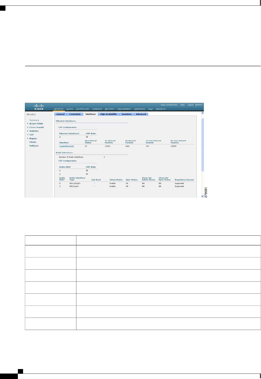
Monitoring the Interface Details
Step 1 Choose Monitor >Summary >All APs. The All APs > Details page appears.
Step 2 Click the Interfaces tab.
Figure 48: Interfaces Tab
Step 3 Click on the available Interface name. The Interface Details page appears.
Step 4 The Interface Details page displays the following parameter details.
Table 21: Interfaces Parameters Details
DescriptionButton
Name of the access point.AP Name
Speed of the interference in Mbps.Link Speed
Total number of bytes in the error-free packets received on the interface.RX Bytes
Total number of unicast packets received on the interface.RX Unicast Packets
Total number of nonunicast or multicast packets received on the interface.RX Non-Unicast Packets
Total number of CRC error in packets while receiving on the interface.Input CRC
Sum of all errors in the packets while receiving on the interface.Input Errors
Cisco Wireless LAN Controller Configuration Guide, Release 7.4
690 OL-28744-01
Monitoring the Interface Details

DescriptionButton
Number of times the receiver hardware was incapable of handling received data to a hardware
buffer because the input rate exceeded the receiver’s capability to handle that data.
Input Overrun
Total number of resource errors in packets received on the interface.Input Resource
Number of packets that are discarded because they are similar to the medium’s minimum
packet size.
Runts
Total number of times the interface advised a sending NIC that it was overwhelmed by
packets being sent and to slow the pace of delivery.
Throttle
Total number of packet retransmitted due to an Ethernet collision.Output Collision
Resource errors in packets transmitted on the interface.Output Resource
Errors that prevented the final transmission of packets out of the interface.Output Errors
Operational state of the physical ethernet interface on the AP.Operational Status
Interface’s duplex mode.
Duplex
Number of bytes in the error-free packets transmitted on the interface.TX Bytes
Total number of unicast packets transmitted on the interface.TX Unicast Packets
Total number of nonunicast or multicast packets transmitted on the interface.TX Non-Unicast Packets
Total number of packets aborted while receiving on the interface.Input Aborts
Total number of packets received incorrectly that has a CRC error and a noninteger number
of octets on the interface.
Input Frames
Total number of packets dropped while receiving on the interface because the queue was
full.
Input Drops
Total number of packets discarded on the interface due to an unknown protocol.Unknown Protocol
Number of packets that are discarded because they exceeded the medium’s maximum packet
size.
Giants
Number of times that an interface has been completely reset.Interface Resets
Total number of packets discarded because there was no buffer space.Output No Buffer
Number of times the transmitter has been running faster than the router can handle.Output Underrun
Cisco Wireless LAN Controller Configuration Guide, Release 7.4
OL-28744-01 691
Monitoring the Interface Details

DescriptionButton
Total number of packets dropped while transmitting from the interface because the queue
was full.
Output Total Drops
Searching for Access Point Radios
Information About Searching for Access Point Radios
You can search for specific access point radios in the list of radios on the 802.11a/n Radios page or the
802.11b/g/n Radios page. You can access these pages from the Monitor tab on the menu bar when viewing
access point radios or from the Wireless tab on the menu bar when configuring access point radios. To search
for specific access point radios, you create a filter to display only radios that meet certain criteria (such as
radio MAC address, access point name, or CleanAir status). This feature is especially useful if your list of
access point radios spans multiple pages, which prevents you from viewing them all at once.
Searching for Access Point Radios (GUI)
Step 1 Perform either of the following:
•Choose Monitor >Access Points Summary >802.11a/n (or 802.11b/g/n) >Radios >Details to open the 802.11a/n
(or 802.11b/g/n) Radios page.
•Choose Wireless >Access Points >Radios >802.11a/n (or 802.11b/g/n) to open the 802.11a/n (or 802.11b/g/n)
Radios page.
These pages show all of the 802.11a/n or 802.11b/g/n access point radios that are joined to the controller and their
current settings.
The total number of access point radios appears in the upper right-hand corner of the page. If the list of radios spans
multiple pages, you can access these pages by clicking the page number links. Each page shows up to 25 access
point radios.
In a Cisco Unified Wireless Network environment, the 802.11a/n and 802.11b/g/n radios should not be
differentiated based on their Base Radio MAC addresses, as they may have the same addresses. Instead,
the radios should be differentiated based on their physical addresses.
Note
Step 2 Click Change Filter to open the Search AP dialog box.
Step 3 Select one of the following check boxes to specify the criteria used when displaying access point radios:
•MAC Address—Base radio MAC address of an access point radio.
•AP Name—Access point name.
Cisco Wireless LAN Controller Configuration Guide, Release 7.4
692 OL-28744-01
Searching for Access Point Radios

When you enable the MAC address filter, the other filters are disabled automatically. When you enable
any of the other filters, the MAC address filter is disabled automatically.
Note
•CleanAir Status—Select one or more of the following check boxes to specify the operating status of the access
points:
◦UP—The spectrum sensor for the access point radio is currently operational.
◦DOWN—The spectrum sensor for the access point radio is currently not operational because an error has
occurred. The most likely reason for the error is that the access point radio is disabled.
◦ERROR—The spectrum sensor for the access point radio has crashed, making CleanAir monitoring
nonoperational for this radio. We recommend rebooting the access point or disabling CleanAir functionality
on the radio.
◦N/A—The access point radio is not capable of supporting CleanAir functionality. Currently, only Cisco
Aironet 3500 series access point radios can be configured for Cisco CleanAir.
Step 4 Click Find to commit your changes. Only the access point radios that match your search criteria appear on the 802.11a/n
Radios page or the 802.11b/g/n Radios page, and the Current Filter parameter at the top of the page specifies the filter
used to generate the list (for example, MAC Address:00:1e:f7:75:0a:a0 or AP Name:pmsk-ap).
If you want to remove the filter and display the entire access point radio list, click Clear
Filter.
Note
Cisco Wireless LAN Controller Configuration Guide, Release 7.4
OL-28744-01 693
Searching for Access Point Radios

Cisco Wireless LAN Controller Configuration Guide, Release 7.4
694 OL-28744-01
Searching for Access Point Radios

CHAPTER 103
Searching for Access Point Radios
•Information About Searching for Access Point Radios, page 695
•Searching for Access Point Radios (GUI), page 695
Information About Searching for Access Point Radios
You can search for specific access point radios in the list of radios on the 802.11a/n Radios page or the
802.11b/g/n Radios page. You can access these pages from the Monitor tab on the menu bar when viewing
access point radios or from the Wireless tab on the menu bar when configuring access point radios. To search
for specific access point radios, you create a filter to display only radios that meet certain criteria (such as
radio MAC address, access point name, or CleanAir status). This feature is especially useful if your list of
access point radios spans multiple pages, which prevents you from viewing them all at once.
Searching for Access Point Radios (GUI)
Step 1 Perform either of the following:
•Choose Monitor >Access Points Summary >802.11a/n (or 802.11b/g/n) >Radios >Details to open the 802.11a/n
(or 802.11b/g/n) Radios page.
•Choose Wireless >Access Points >Radios >802.11a/n (or 802.11b/g/n) to open the 802.11a/n (or 802.11b/g/n)
Radios page.
These pages show all of the 802.11a/n or 802.11b/g/n access point radios that are joined to the controller and their
current settings.
The total number of access point radios appears in the upper right-hand corner of the page. If the list of radios spans
multiple pages, you can access these pages by clicking the page number links. Each page shows up to 25 access
point radios.
In a Cisco Unified Wireless Network environment, the 802.11a/n and 802.11b/g/n radios should not be
differentiated based on their Base Radio MAC addresses, as they may have the same addresses. Instead,
the radios should be differentiated based on their physical addresses.
Note
Cisco Wireless LAN Controller Configuration Guide, Release 7.4
OL-28744-01 695

Step 2 Click Change Filter to open the Search AP dialog box.
Step 3 Select one of the following check boxes to specify the criteria used when displaying access point radios:
•MAC Address—Base radio MAC address of an access point radio.
•AP Name—Access point name.
When you enable the MAC address filter, the other filters are disabled automatically. When you enable
any of the other filters, the MAC address filter is disabled automatically.
Note
•CleanAir Status—Select one or more of the following check boxes to specify the operating status of the access
points:
◦UP—The spectrum sensor for the access point radio is currently operational.
◦DOWN—The spectrum sensor for the access point radio is currently not operational because an error has
occurred. The most likely reason for the error is that the access point radio is disabled.
◦ERROR—The spectrum sensor for the access point radio has crashed, making CleanAir monitoring
nonoperational for this radio. We recommend rebooting the access point or disabling CleanAir functionality
on the radio.
◦N/A—The access point radio is not capable of supporting CleanAir functionality. Currently, only Cisco
Aironet 3500 series access point radios can be configured for Cisco CleanAir.
Step 4 Click Find to commit your changes. Only the access point radios that match your search criteria appear on the 802.11a/n
Radios page or the 802.11b/g/n Radios page, and the Current Filter parameter at the top of the page specifies the filter
used to generate the list (for example, MAC Address:00:1e:f7:75:0a:a0 or AP Name:pmsk-ap).
If you want to remove the filter and display the entire access point radio list, click Clear
Filter.
Note
Cisco Wireless LAN Controller Configuration Guide, Release 7.4
696 OL-28744-01
Searching for Access Point Radios (GUI)

CHAPTER 104
Configuring Global Credentials for Access Points
•Information About Configuring Global Credentials for Access Points, page 697
•Restrictions for Global Credentials for Access Points, page 698
•Configuring Global Credentials for Access Points (GUI), page 698
•Configuring Global Credentials for Access Points (CLI), page 699
Information About Configuring Global Credentials for Access Points
Cisco IOS access points are shipped from the factory with Cisco as the default enable password. This password
allows users to log onto the nonprivileged mode and enter show and debug commands, which poses a security
threat. The default enable password must be changed to prevent unauthorized access and to enable users to
enter configuration commands from the access point’s console port.
The following are some guidelines to configure global credentials for access points:
•You can set a global username, password, and enable password that all access points that are currently
joined to the controller and any that join in the future inherit as they join the controller. If desired, you
can override the global credentials and assign a unique username, password, and enable password for a
specific access point.
•After an access point joins the controller, the access point enables console port security, and you are
prompted for your username and password whenever you log into the access point’s console port. When
you log on, you are in nonprivileged mode, and you must enter the enable password in order to use the
privileged mode.
•The global credentials that you configure on the controller are retained across controller and access point
reboots. They are overwritten only if the access point joins a new controller that is configured with a
global username and password. If the new controller is not configured with global credentials, the access
point retains the global username and password configured for the first controller.
•You must keep track of the credentials used by the access points. Otherwise, you might not be able to
log onto the console port of the access point. If you need to return the access points to the default
Cisco/Cisco username and password, you must clear the controller’s configuration and the access point’s
configuration to return them to factory-default settings. To clear the controller’s configuration, choose
Commands >Reset to Factory Default >Reset on the controller GUI, or enter the clear config
command on the controller CLI. To clear the access point’s configuration, choose Wireless >Access
Cisco Wireless LAN Controller Configuration Guide, Release 7.4
OL-28744-01 697

Points >All APs, click the AP name and click Clear All Config on the controller GUI, or enter the
clear ap config Cisco_AP command on the controller CLI. To clear the access point's configuration
except its static IP address, choose Wireless >Access Points >All APs, click the AP name and click
Clear Config Except Static IP, or enter the clear ap config ap-name keep-ip-config command on the
controller CLI. After the access point rejoins a controller, it adopts the default Cisco/Cisco username
and password.
Suppose you configure an indoor Cisco AP to go into the mesh mode. If you want to
reset the Cisco AP to the local mode, use the test mesh mode local command.
Note
•To reset the AP hardware, choose Wireless >Access Points >All APs, click the AP name and click
Reset AP Now.
Restrictions for Global Credentials for Access Points
•The controller software features are supported on all access points that have been converted to lightweight
mode except the 1100 series. VxWorks access points are not supported.
Configuring Global Credentials for Access Points (GUI)
Step 1 Choose Wireless >Access Points >Global Configuration to open the Global Configuration page.
Step 2 In the Username text box, enter the username that is to be inherited by all access points that join the controller.
Step 3 In the Password text box, enter the password that is to be inherited by all access points that join the controller.
You can set a global username, password, and enable password that all access points inherit as they join the controller
including access points that are currently joined to the controller and any that join in the future. You can override the
global credentials and assign a unique username, password, and enable password for a specific access point. The following
are requirements enforced on the password:
•The password should contain characters from at least three of the following classes: lowercase letters, uppercase
letters, digits, and special characters.
•No character in the password can be repeated more than three times consecutively.
•The password should not contain the management username or the reverse of the username.
•The password should not contain words like Cisco, oscic, admin, nimda or any variant obtained by changing the
capitalization of letters by substituting 1, |, or ! or substituting 0 for o or substituting $ for s.
Cisco Wireless LAN Controller Configuration Guide, Release 7.4
698 OL-28744-01
Restrictions for Global Credentials for Access Points

Step 4 In the Enable Password text box, enter the enable password that is to be inherited by all access points that join the
controller.
Step 5 Click Apply to send the global username, password, and enable password to all access points that are currently joined
to the controller or that join the controller in the future.
Step 6 Click Save Configuration to save your changes.
Step 7 (Optional) Override the global credentials for a specific access point and assign a unique username, password, and enable
password to this access point as follows:
a) Choose Access Points >All APs to open the All APs page.
b) Click the name of the access point for which you want to override the global credentials.
c) Choose the Credentials tab. The All APs > Details for (Credentials) page appears.
d) Select the Over-ride Global Credentials check box to prevent this access point from inheriting the global username,
password, and enable password from the controller. The default value is unselected.
e) In the Username, Password, and Enable Password text boxes, enter the unique username, password, and enable
password that you want to assign to this access point.
The information that you enter is retained across controller and access point reboots and if the access point
joins a new controller.
Note
f) Click Apply to commit your changes.
g) Click Save Configuration to save your changes.
If you want to force this access point to use the controller’s global credentials, unselect the Over-ride Global
Credentials check box.
Note
Configuring Global Credentials for Access Points (CLI)
Step 1 Configure the global username, password, and enable password for all access points currently joined to the controller as
well as any access points that join the controller in the future by entering this command:
config ap mgmtuser add username user password password enablesecret enable_password all
Step 2 (Optional) Override the global credentials for a specific access point and assign a unique username, password, and enable
password to this access point by entering this command:
config ap mgmtuser add username user password password enablesecret enable_password Cisco_AP
The credentials that you enter in this command are retained across controller and access point reboots and if the access
point joins a new controller.
If you want to force this access point to use the controller’s global credentials, enter the config ap mgmtuser
delete Cisco_AP command. The following message appears after you execute this command: “AP reverted to
global username configuration.”
Note
Step 3 Enter the save config command to save your changes.
Step 4 Verify that global credentials are configured for all access points that join the controller by entering this command:
show ap summary
If global credentials are not configured, the Global AP User Name text box shows “Not Configured.”
Note
To view summary of specific access point you can specify the access point name. You can also use wildcard searches
when filtering for access points.
Cisco Wireless LAN Controller Configuration Guide, Release 7.4
OL-28744-01 699
Configuring Global Credentials for Access Points (CLI)

Step 5 See the global credentials configuration for a specific access point by entering this command:
show ap config general Cisco_AP
The name of the access point is case
sensitive.
Note
If this access point is configured for global credentials, the AP User Mode text boxes shows “Automatic.”If the
global credentials have been overwritten for this access point, the AP User Mode text box shows “Customized.”
Note
Cisco Wireless LAN Controller Configuration Guide, Release 7.4
700 OL-28744-01
Configuring Global Credentials for Access Points (CLI)

CHAPTER 105
Configuring Authentication for Access Points
•Information About Configuring Authentication for Access Points, page 701
•Prerequisites for Configuring Authentication for Access Points, page 701
•Restrictions for Authenticating Access Points, page 702
•Configuring Authentication for Access Points (GUI), page 702
•Configuring Authentication for Access Points (CLI), page 703
•Configuring the Switch for Authentication, page 704
Information About Configuring Authentication for Access Points
You can configure 802.1X authentication between a lightweight access point and a Cisco switch. The access
point acts as an 802.1X supplicant and is authenticated by the switch using EAP-FAST with anonymous PAC
provisioning.
You can configure global authentication settings that all access points that are currently associated with the
controller and any that associate in the future. You can also override the global authentication settings and
assign unique authentication settings for a specific access point.
Prerequisites for Configuring Authentication for Access Points
Step 1 If the access point is new, do the following:
a) Boot the access point with the installed recovery image.
b) If you choose not to follow this suggested flow and instead enable 802.1X authentication on the switch port connected
to the access point prior to the access point joining the controller, enter this command:
lwapp ap dot1x username username password password
If you choose to follow this suggested flow and enable 802.1X authentication on the switch port after the
access point has joined the controller and received the configured 802.1X credentials, you do not need to
enter this command.
Note
Cisco Wireless LAN Controller Configuration Guide, Release 7.4
OL-28744-01 701

This command is available only for access points that are running the 5.1, 5.2, 6.0, or 7.0 recovery
image.
Connect the access point to the switch port.
Note
Step 2 Install the 5.1, 5.2, 6.0, or 7.0 image on the controller and reboot the controller.
Step 3 Allow all access points to join the controller.
Step 4 Configure authentication on the controller. See the Configuring Authentication for Access Points (GUI) section or the
Configuring Authentication for Access Points (CLI) section for information about configuring authentication on the
controller.
Step 5 Configure the switch to allow authentication. See the Configuring the Switch for Authentication section for information
about configuring the switch for authentication.
Restrictions for Authenticating Access Points
•The OEAP 600 Series access points do not support LEAP.
Configuring Authentication for Access Points (GUI)
Step 1 Choose Wireless >Access Points >Global Configuration to open the Global Configuration page.
Step 2 Under 802.1x Supplicant Credentials, select the 802.1x Authentication check box.
Step 3 In the Username text box, enter the username that is to be inherited by all access points that join the controller.
Step 4 In the Password and Confirm Password text boxes, enter the password that is to be inherited by all access points that
join the controller.
You must enter a strong password in these text boxes. Strong passwords have the following characteristics:Note
•They are at least eight characters long
•They contain a combination of uppercase and lowercase letters, numbers, and symbols
•They are not a word in any language
Step 5 Click Apply to send the global authentication username and password to all access points that are currently joined to
the controller and to any that join the controller in the future.
Step 6 Click Save Configuration to save your changes.
Step 7 If desired, you can choose to override the global authentication settings and assign a unique username and password to
a specific access point as follows:
a) Choose Access Points >All APs to open the All APs page.
b) Click the name of the access point for which you want to override the authentication settings.
c) Click the Credentials tab to open the All APs > Details for (Credentials) page.
d) Under 802.1x Supplicant Credentials, select the Over-ride Global Credentials check box to prevent this access
point from inheriting the global authentication username and password from the controller. The default value is
unselected.
Cisco Wireless LAN Controller Configuration Guide, Release 7.4
702 OL-28744-01
Restrictions for Authenticating Access Points

e) In the Username, Password, and Confirm Password text boxes, enter the unique username and password that you
want to assign to this access point.
The information that you enter is retained across controller and access point reboots and whenever the access
point joins a new controller.
Note
f) Click Apply to commit your changes.
g) Click Save Configuration to save your changes.
If you want to force this access point to use the controller’s global authentication settings, unselect the
Over-ride Global Credentials check box.
Note
Configuring Authentication for Access Points (CLI)
Step 1 Configure the global authentication username and password for all access points currently joined to the controller as
well as any access points that join the controller in the future by entering this command:
config ap 802.1Xuser add username ap-username password ap-password all
You must enter a strong password for the ap-password parameter. Strong passwords have the following
characteristics:
Note
•They are at least eight characters long.
•They contain a combination of uppercase and lowercase letters, numbers, and symbols.
•They are not a word in any language.
Step 2 (Optional) Override the global authentication settings and assign a unique username and password to a specific access
point. To do so, enter this command:
config ap 802.1Xuser add username ap-username password ap-password Cisco_AP
You must enter a strong password for the ap-password parameter. See the note in Step 1 for the characteristics
of strong passwords.
Note
The authentication settings that you enter in this command are retained across controller and access point reboots and
whenever the access point joins a new controller.
If you want to force this access point to use the controller’s global authentication settings, enter the config ap
802.1Xuser delete Cisco_AP command. The following message appears after you execute this command: “AP
reverted to global username configuration.”
Note
Step 3 Enter the save config command to save your changes.
Step 4 (Optional) Disable 802.1X authentication for all access points or for a specific access point by entering this command:
config ap 802.1Xuser disable {all |Cisco_AP}
You can disable 802.1X authentication for a specific access point only if global 802.1X authentication is not
enabled. If global 802.1X authentication is enabled, you can disable 802.1X for all access points only.
Note
Step 5 See the authentication settings for all access points that join the controller by entering this command:
show ap summary
Cisco Wireless LAN Controller Configuration Guide, Release 7.4
OL-28744-01 703
Configuring Authentication for Access Points (CLI)

Information similar to the following appears:
Number of APs.................................... 1
Global AP User Name.............................. globalap
Global AP Dot1x User Name........................ globalDot1x
Step 6 See the authentication settings for a specific access point by entering this command:
show ap config general Cisco_AP
The name of the access point is case
sensitive.
Note
If this access point is configured for global authentication, the AP Dot1x User Mode text boxes shows “Automatic.”
If the global authentication settings have been overwritten for this access point, the AP Dot1x User Mode text
box shows “Customized.”
Note
Configuring the Switch for Authentication
To enable 802.1X authentication on a switch port, on the switch CLI, enter these commands:
•Switch# configure terminal
•Switch(config)# dot1x system-auth-control
•Switch(config)# aaa new-model
•Switch(config)# aaa authentication dot1x default group radius
•Switch(config)# radius-server host ip_addr auth-port port acct-port port key key
•Switch(config)# interface fastethernet2/1
•Switch(config-if)# switchport mode access
•Switch(config-if)# dot1x pae authenticator
•Switch(config-if)# dot1x port-control auto
•Switch(config-if)# end
Cisco Wireless LAN Controller Configuration Guide, Release 7.4
704 OL-28744-01
Configuring the Switch for Authentication

CHAPTER 106
Configuring Embedded Access Points
•Information About Embedded Access Points, page 705
Information About Embedded Access Points
Controller software release 7.0.116.0 or later releases support the embedded access points: AP801 and AP802,
which are the integrated access points on the Cisco 880 Series Integrated Services Routers (ISRs). This access
points use a Cisco IOS software image that is separate from the router Cisco IOS software image. The access
points can operate as autonomous access points configured and managed locally, or they can operate as
centrally managed access points that utilize the CAPWAP or LWAPP protocol. The AP801 and AP802 access
points are preloaded with both an autonomous Cisco IOS release and a recovery image for the unified mode.
The following are some guidelines for embedded access points:
•Before you use an AP801 or AP802 Series Lightweight Access Point with controller software release
7.0.116.0 or later releases, you must upgrade the software in the Next Generation Cisco 880 Series
Integrated Services Routers (ISRs) to Cisco IOS 151-4.M or later.
In Release 7.4, all AP modes except bridging (required for mesh) are supported for both
AP801 and AP802. In Release 7.5 and later, all AP modes are supported on AP802;
however, bridging is not supported on AP801.
Note
•When you want to use the AP801 or AP802 with a controller, you must enable the recovery image for
the unified mode on the access point by entering the service-module wlan-ap 0 bootimage unified
command on the router in privileged EXEC mode.
•If the service-module wlan-ap 0 bootimage unified command does not work, make sure that the
software license is still eligible.
•After enabling the recovery image, enter the service-module wlan-ap 0 reload command on the router
to shut down and reboot the access point. After the access point reboots, it discovers the controller,
downloads the full CAPWAP or LWAPP software release from the controller, and acts as a lightweight
access point.
Cisco Wireless LAN Controller Configuration Guide, Release 7.4
OL-28744-01 705

To use the CLI commands mentioned above, the router must be running Cisco IOS
Release 12.4(20)T or later releases.
Note
•To support CAPWAP or LWAPP, the router must be activated with at least the Cisco Advanced IP
Services IOS license-grade image. A license is required to upgrade to this Cisco IOS image on the router.
For licensing information, see http://www.cisco.com/en/US/docs/routers/access/sw_activation/SA_on_
ISR.html
•After the AP801 or AP802 boots up with the recovery image for the unified mode, it requires an IP
address to communicate with the controller and to download its unified image and configuration from
the controller. The router can provide DHCP server functionality, the DHCP pool to reach the controller,
and setup option 43 for the controller IP address in the DHCP pool configuration. Use the following
configuration to perform this task:
ip dhcp pool pool_name
network ip_address subnet_mask
dns-server ip_address
default-router ip_address
option 43 hex controller_ip_address_in_hex
Example:
ip dhcp pool embedded-ap-pool
network 60.0.0.0 255.255.255.0
dns-server 171.70.168.183
default-router 60.0.0.1
option 43 hex f104.0a0a.0a0f /* single WLC IP address(10.10.10.15) in hex format
*/
•The AP801 and AP802 802.11n radio supports lower power levels than the 802.11n radio in the Cisco
Aironet 1250 series access points. The AP801 and AP802 access points store the radio power levels and
passes them to the controller when the access point joins the controller. The controller uses the supplied
values to limit the user’s configuration.
•The AP801 and AP802 access points can be used in FlexConnect mode.
For more information about the AP801, see the documentation for the Cisco 800 Series ISRs at this URL:
http://www.cisco.com/en/US/products/hw/routers/ps380/tsd_products_support_series_home.html
For more information about the AP802, see the documentation for the Next generation Cisco 880 Series ISRs
at this URL: http://www.cisco.com/en/US/docs/routers/access/800/860-880-890/software/configuration/guide/
SCG_880_series.pdf
Cisco Wireless LAN Controller Configuration Guide, Release 7.4
706 OL-28744-01
Information About Embedded Access Points

CHAPTER 107
Converting Autonomous Access Points to
Lightweight Mode
•Information About Converting Autonomous Access Points to Lightweight Mode, page 707
•Restrictions for Converting Autonomous Access Points to Lightweight Mode, page 708
•Reverting from Lightweight Mode to Autonomous Mode, page 708
•Authorizing Access Points, page 709
•Configuring VLAN Tagging for CAPWAP Frames from Access Points, page 715
•Using DHCP Option 43 and DHCP Option 60, page 716
•Troubleshooting the Access Point Join Process, page 717
•Sending Debug Commands to Access Points Converted to Lightweight Mode, page 721
•Understanding How Converted Access Points Send Crash Information to the Controller, page 721
•Understanding How Converted Access Points Send Radio Core Dumps to the Controller, page 721
•Uploading Memory Core Dumps from Converted Access Points, page 723
•Viewing the AP Crash Log Information, page 724
•Displaying MAC Addresses for Converted Access Points, page 725
•Disabling the Reset Button on Access Points Converted to Lightweight Mode, page 725
•Configuring a Static IP Address on a Lightweight Access Point, page 726
•Supporting Oversized Access Point Images, page 727
Information About Converting Autonomous Access Points to Lightweight Mode
You can use an upgrade conversion tool to convert autonomous Cisco Aironet 1100, 1130AG, 1200, 1240AG,
1260, and 1300 Series Access Points to lightweight mode. When you upgrade one of these access points to
lightweight mode, the access point communicates with a controller and receives a configuration and software
image from the controller.
Cisco Wireless LAN Controller Configuration Guide, Release 7.4
OL-28744-01 707

See the Upgrading Autonomous Cisco Aironet Access Points to Lightweight Mode document for instructions
to upgrade an autonomous access point to lightweight mode:
http://www.cisco.com/en/US/docs/wireless/access_point/conversion/lwapp/upgrade/guide/lwapnote.html
The following are some guidelines for converting autonomous APs to lightweight mode APs:
•All Cisco lightweight access points support 16 BSSIDs per radio and a total of 16 wireless LANs per
access point. When a converted access point associates with a controller, only wireless LANs with IDs
1 through 16 are pushed to the access point.
•Access points converted to lightweight mode must get an IP address and discover the controller using
DHCP, DNS, or IP subnet broadcast.
•The 1130AG and 1240AG access points support FlexConnect mode.
Restrictions for Converting Autonomous Access Points to Lightweight Mode
•Access points converted to lightweight mode do not support Wireless Domain Services (WDS). Converted
access points communicate only with Cisco wireless LAN controllers and cannot communicate with
WDS devices. However, the controller provides functionality that is equivalent to WDS when the access
point associates to it.
•After you convert an access point to lightweight mode, the console port provides read-only access to
the unit.
Reverting from Lightweight Mode to Autonomous Mode
After you use the upgrade tool to convert an autonomous access point to lightweight mode, you can convert
the access point from a lightweight unit back to an autonomous unit by loading a Cisco IOS release that
supports autonomous mode (Cisco IOS Release 12.3(7)JA or earlier releases). If the access point is associated
to a controller, you can use the controller to load the Cisco IOS release. If the access point is not associated
to a controller, you can load the Cisco IOS release using TFTP. In either method, the access point must be
able to access a TFTP server that contains the Cisco IOS release to be loaded.
Reverting to a Previous Release (CLI)
Step 1 Log on to the CLI on the controller to which the access point is associated.
Step 2 Revert from lightweight mode, by entering this command:
config ap tftp-downgrade tftp-server-ip-address filename access-point-name
Step 3 Wait until the access point reboots and reconfigure the access point using the CLI or GUI.
Cisco Wireless LAN Controller Configuration Guide, Release 7.4
708 OL-28744-01
Restrictions for Converting Autonomous Access Points to Lightweight Mode

Reverting to a Previous Release Using the MODE Button and a TFTP Server
Step 1 Configure the PC on which your TFTP server software runs with a static IP address in the range of 10.0.0.2 to 10.0.0.30.
Step 2 Make sure that the PC contains the access point image file (such as c1200-k9w7-tar.123-7.JA.tar for a 1200 series access
point) in the TFTP server folder and that the TFTP server is activated.
Step 3 Rename the access point image file in the TFTP server folder to c1200-k9w7-tar.default for a 1200 series access point.
Step 4 Connect the PC to the access point using a Category 5 (CAT5) Ethernet cable.
Step 5 Disconnect power from the access point.
Step 6 Press and hold the MODE button while you reconnect power to the access point.
The MODE button on the access point must be enabled. Follow the steps in the Disabling the Reset Button on
Access Points Converted to Lightweight Mode to select the status of the access point MODE button.
Note
Step 7 Hold the MODE button until the status LED turns red (approximately 20 to 30 seconds), and release the MODE button.
Step 8 Wait until the access point reboots as indicated by all LEDs turning green followed by the Status LED blinking green.
Step 9 After the access point reboots, reconfigure the access point using the GUI or the CLI.
Authorizing Access Points
In controller software releases prior to 5.2, the controller may either use self-signed certificates (SSCs) to
authenticate access points or send the authorization information to a RADIUS server (if access points have
manufactured-installed certificates [MICs]). In controller software release 5.2 or later releases, you can
configure the controller to use a local significant certificate (LSC).
Authorizing Access Points Using SSCs
The Control and Provisioning of Wireless Access Points protocol (CAPWAP) secures the control
communication between the access point and controller by a secure key distribution requiring X.509 certificates
on both the access point and controller. CAPWAP relies on provisioning of the X.509 certificates. Cisco
Aironet access points shipped before July 18, 2005 do not have a MIC, so these access points create an SSC
when upgraded to operate in lightweight mode. Controllers are programmed to accept local SSCs for
authentication of specific access points and do not forward those authentication requests to a RADIUS server.
This behavior is acceptable and secure.
Authorizing Access Points for Virtual Controllers Using SSC
Virtual controllers use SSC certificates instead of Manufacturing Installed Certificates (MIC) used by physical
controllers. You can configure the controller to allow an AP to validate the SSC of the virtual controller.
When an AP validates the SSC, the AP checks if the hash key of the virtual controller matches the hash key
stored in its flash. If a match is found, the AP associates with the controller. If a match is not found, the
validation fails and the AP disconnects from the controller and restarts the discovery process. By default, hash
validation is enabled. An AP must have the virtual controller hash key in its flash before associating with the
virtual controller. If you disable hash validation of the SSC, the AP bypasses the hash validation and directly
moves to the Run state. APs can associate with a physical controller, download the hash keys and then associate
Cisco Wireless LAN Controller Configuration Guide, Release 7.4
OL-28744-01 709
Authorizing Access Points

with a virtual controller. If the AP is associated with a physical controller and hash validation is disabled, the
AP associates with any virtual controller without hash validation. The hash key of the virtual controller can
be configured for a mobility group member. This hash key gets pushed to the APs, so that the APs can validate
the hash key of the controller.
Configuring SSC (GUI)
Step 1 Choose Security >Certificate >SSC to open the Self Significant Certificates (SSC) page.
The SSC device certification details are displayed.
Step 2 Select the Enable SSC Hash Validation check box to enable the validation of the hash key.
Step 3 Click Apply to commit your changes.
Configuring SSC (CLI)
Step 1 To configure hash validation of SSC, enter this command:
config certificate ssc hash validation {enable |disable}
Step 2 To see the hash key details, enter this command:
show certificate ssc
Authorizing Access Points Using MICs
You can configure controllers to use RADIUS servers to authorize access points using MICs. The controller
uses an access point’s MAC address as both the username and password when sending the information to a
RADIUS server. For example, if the MAC address of the access point is 000b85229a70, both the username
and password used by the controller to authorize the access point are 000b85229a70.
The lack of a strong password by the use of the access point’s MAC address should not be an issue because
the controller uses MIC to authenticate the access point prior to authorizing the access point through the
RADIUS server. Using MIC provides strong authentication.
Note
If you use the MAC address as the username and password for access point authentication on a RADIUS
AAA server, do not use the same AAA server for client authentication.
Note
Cisco Wireless LAN Controller Configuration Guide, Release 7.4
710 OL-28744-01
Authorizing Access Points

Authorizing Access Points Using LSCs
You can use an LSC if you want your own public key infrastructure (PKI) to provide better security, to have
control of your certificate authority (CA), and to define policies, restrictions, and usages on the generated
certificates.
The LSC CA certificate is installed on access points and controllers. You need to provision the device certificate
on the access point. The access point gets a signed X.509 certificate by sending a certRequest to the controller.
The controller acts as a CA proxy and receives the certRequest signed by the CA for the access point.
When the CA server is in manual mode and if there is an AP entry in the LSC SCEP table that is pending
enrollment, the controller waits for the CA server to send a pending response. If there is no response from
the CA server, the controller retries a total of three times to get a response, after which the fallback mode
comes into effect where the AP provisioning times out and the AP reboots and comes up with MIC.
Note
LSC on controller does not take password challenge. Therefore, for LSC to work, you must disable
password challenge on the CA server. Also, you cannot use Microsoft Windows Server 2008 as a CA
server because it is not possible to disable password challenge on it.
Note
Configuring Locally Significant Certificates (GUI)
Step 1 Choose Security >Certificate >LSC to open the Local Significant Certificates (LSC) - General page.
Step 2 Select the Enable LSC on Controller check box to enable the LSC on the system.
Step 3 In the CA Server URL text box, enter the URL to the CA server. You can enter either a domain name or an IP address.
Step 4 In the Params text boxes, enter the parameters for the device certificate. The key size is a value from 384 to 2048 (in
bits), and the default value is 2048.
Step 5 Click Apply to commit your changes.
Step 6 To add the CA certificate into the controller’s CA certificate database, hover your cursor over the blue drop-down arrow
for the certificate type and choose Add.
Step 7 Choose the AP Provisioning tab to open the Local Significant Certificates (LSC) - AP Provisioning page.
Step 8 Select the Enable check box and click Update to provision the LSC on the access point.
Step 9 When a message appears indicating that the access points will be rebooted, click OK.
Step 10 In the Number of Attempts to LSC text box, enter the number of times that the access point attempts to join the controller
using an LSC before the access point reverts to the default certificate (MIC or SSC). The range is 0 to 255 (inclusive),
and the default value is 3.
If you set the number of retries to a nonzero value and the access point fails to join the controller using an LSC
after the configured number of retries, the access point reverts to the default certificate. If you set the number
of retries to 0 and the access point fails to join the controller using an LSC, the access point does not attempt
to join the controller using the default certificate.
Note
If you are configuring LSC for the first time, we recommend that you configure a nonzero
value.
Note
Cisco Wireless LAN Controller Configuration Guide, Release 7.4
OL-28744-01 711
Authorizing Access Points

Step 11 Enter the access point MAC address in the AP Ethernet MAC Addresses text box and click Add to add access points to
the provision list.
To remove an access point from the provision list, hover your cursor over the blue drop-down arrow for the
access point and choose Remove.
Note
If you configure an access point provision list, only the access points in the provision list are provisioned when
you enable AP provisioning. If you do not configure an access point provision list, all access points with a MIC
or SSC certificate that join the controller are LSC provisioned.
Note
Step 12 Click Apply to commit your changes.
Step 13 Click Save Configuration to save your changes.
Configuring Locally Significant Certificates (CLI)
Step 1 Enable LSC on the system by entering this command:
config certificate lsc {enable |disable}
Step 2 Configure the URL to the CA server by entering this command:
config certificate lsc ca-server http://url:port/path
where url can be either a domain name or IP address.
You can configure only one CA server. To configure a different CA server, delete the configured CA server
using the config certificate lsc ca-server delete command, and then configure a different CA server.
Note
Step 3 Add the LSC CA certificate into the controller’s CA certificate database by entering this command:
config certificate lsc ca-cert {add |delete}
Step 4 Configure the parameters for the device certificate by entering this command:
config certificate lsc subject-params country state city orgn dept e-mail
The common name (CN) is generated automatically on the access point using the current MIC/SSC format
Cxxxx-MacAddr, where xxxx is the product number.
Note
Step 5 Configure a key size by entering this command:
config certificate lsc other-params keysize
The keysize is a value from 384 to 2048 (in bits), and the default value is 2048.
Step 6 Add access points to the provision list by entering this command:
config certificate lsc ap-provision auth-list add AP_mac_addr
To remove access points from the provision list, enter the config certificate lsc ap-provision auth-list delete
AP_mac_addr command.
Note
If you configure an access point provision list, only the access points in the provision list are provisioned when
you enable AP provisioning (in Step 8). If you do not configure an access point provision list, all access points
with a MIC or SSC certificate that join the controller are LSC provisioned.
Note
Step 7 Configure the number of times that the access point attempts to join the controller using an LSC before the access point
reverts to the default certificate (MIC or SSC) by entering this command:
config certificate lsc ap-provision revert-cert retries
where retries is a value from 0 to 255, and the default value is 3.
Cisco Wireless LAN Controller Configuration Guide, Release 7.4
712 OL-28744-01
Authorizing Access Points

If you set the number of retries to a nonzero value and the access point fails to join the controller using an LSC
after the configured number of retries, the access point reverts to the default certificate. If you set the number
of retries to 0 and the access point fails to join the controller using an LSC, the access point does not attempt
to join the controller using the default certificate.
Note
If you are configuring LSC for the first time, we recommend that you configure a nonzero
value.
Note
Step 8 Provision the LSC on the access point by entering this command:
config certificate lsc ap-provision {enable |disable}
Step 9 See the LSC summary by entering this command:
show certificate lsc summary
Information similar to the following appears:
LSC Enabled.......................................... Yes
LSC CA-Server........................................ http://10.0.0.1:8080/caserver
LSC AP-Provisioning.................................. Yes
Provision-List................................... Not Configured
LSC Revert Count in AP reboots................... 3
LSC Params:
Country.......................................... 4
State............................................ ca
City............................................. ss
Orgn............................................. org
Dept............................................. dep
Email............................................ dep@co.com
KeySize.......................................... 390
LSC Certs:
CA Cert.......................................... Not Configured
RA Cert....................................... Not Configured
Step 10 See details about the access points that are provisioned using LSC by entering this command:
show certificate lsc ap-provision
Information similar to the following appears:
LSC AP-Provisioning........................... Yes
Provision-List................................ Present
Idx Mac Address
--- ------------
1 00:18:74:c7:c0:90
Cisco Wireless LAN Controller Configuration Guide, Release 7.4
OL-28744-01 713
Authorizing Access Points

Authorizing Access Points (GUI)
Step 1 Choose Security >AAA >AP Policies to open the AP Policies page.
Step 2 If you want the access point to accept self-signed certificates (SSCs), manufactured-installed certificates (MICs), or local
significant certificates (LSCs), select the appropriate check box.
Step 3 If you want the access points to be authorized using a AAA RADIUS server, select the Authorize MIC APs against
auth-list or AAA check box.
Step 4 If you want the access points to be authorized using an LSC, select the Authorize LSC APs against auth-list check
box.
Step 5 Click Apply to commit your changes.
Step 6 Follow these steps to add an access point to the controller’s authorization list:
a) Click Add to access the Add AP to Authorization List area.
b) In the MAC Address text box, enter the MAC address of the access point.
c) From the Certificate Type drop-down list, choose MIC,SSC, or LSC.
d) Click Add. The access point appears in the access point authorization list.
To remove an access point from the authorization list, hover your cursor over the blue drop-down arrow for
the access point and choose Remove.
Note
To search for a specific access point in the authorization list, enter the MAC address of the access point in
the Search by MAC text box and click Search.
Note
Authorizing Access Points (CLI)
•Configure an access point authorization policy by entering this command:
config auth-list ap-policy {authorize-ap {enable |disable} | authorize-lsc-ap {enable |disable}}
•Configure an access point to accept manufactured-installed certificates (MICs), self-signed certificates
(SSCs), or local significant certificates (LSCs) by entering this command:
config auth-list ap-policy {mic | ssc |lsc {enable |disable}}
•Configure the user name to be used in access point authorization requests.
config auth-list ap-policy {authorize-ap username {ap_name |ap_mac |both}}
•Add an access point to the authorization list by entering this command:
config auth-list add {mic |ssc |lsc}ap_mac [ap_key]
where ap_key is an optional key hash value equal to 20 bytes or 40 digits.
To delete an access point from the authorization list, enter this command: config auth-list delete ap_mac.
Note
•See the access point authorization list by entering this command:
show auth-list
Cisco Wireless LAN Controller Configuration Guide, Release 7.4
714 OL-28744-01
Authorizing Access Points

Configuring VLAN Tagging for CAPWAP Frames from Access Points
Information About VLAN Tagging for CAPWAP Frames from Access Points
You can configure VLAN tagging on the Ethernet interface either directly on the AP console or through the
controller. The configuration is saved in the flash memory and all CAPWAP frames use the VLAN tag as
configured, along with all the locally switched traffic, which is not mapped to a VLAN.
This feature is not supported on mesh access points that are in bridge mode.
Configuring VLAN Tagging for CAPWAP Frames from Access Points (GUI)
Step 1 Choose Wireless >Access Points >All APs to open the All APs page.
Step 2 Click the AP name from the list of AP names to open the Details page for the AP.
Step 3 Click the Advanced tab.
Step 4 In the VLAN Tagging area, select the VLAN Tagging check box.
Step 5 In the Trunk VLAN ID text box, enter an ID.
If the access point is unable to route traffic through the specified trunk VLAN after about 10 minutes, the access point
performs a recovery procedure by rebooting and sending CAPWAP frames in untagged mode to try and reassociate with
the controller. The controller sends a trap to a trap server such as the Cisco Prime Infrastructure, which indicates the
failure of the trunk VLAN.
If the access point is unable to route traffic through the specified trunk VLAN, it untags the packets and reassociates
with the controller. The controller sends a trap to a trap server such as the Cisco Prime Infrastructure, which indicates
the failure of the trunk VLAN.
If the trunk VLAN ID is 0, the access point untags the CAPWAP frames.
The VLAN Tag status is displayed showing whether the AP tags or untags the CAPWAP frames.
Step 6 Click Apply.
Step 7 You are prompted with a warning message saying that the configuration will result in a reboot of the access point. Click
OK to continue.
Step 8 Click Save Configuration.
What to Do Next
After the configuration, the switch or other equipment connected to the Ethernet interface of the AP must also
be configured to support tagged Ethernet frames.
Configuring VLAN Tagging for CAPWAP Frames from Access Points (CLI)
Step 1 Configure VLAN tagging for CAPWAP frames from access points by entering this command:
Cisco Wireless LAN Controller Configuration Guide, Release 7.4
OL-28744-01 715
Configuring VLAN Tagging for CAPWAP Frames from Access Points

config ap ethernet tag {disable |id vlan-id} {ap-name |all}
Step 2 You can see VLAN tagging information for an AP or all APs by entering this command:
show ap ethernet tag {summary |ap-name}
Using DHCP Option 43 and DHCP Option 60
Cisco Aironet access points use the type-length-value (TLV) format for DHCP option 43. DHCP servers must
be programmed to return the option based on the access point’s DHCP Vendor Class Identifier (VCI) string
(DHCP option 60).
This table lists the VCI strings for Cisco access points capable of operating in lightweight mode.
Table 22: VCI Strings For Lightweight Access Points
VCI StringAccess Point
Cisco AP c1040Cisco Aironet 1040 Series
Cisco AP c1130Cisco Aironet 1130 Series
Cisco AP c1140Cisco Aironet 1140 Series
Cisco AP c1240Cisco Aironet 1240 Series
Cisco AP c1250Cisco Aironet 1250 Series
Cisco AP c1260Cisco Aironet 1260 Series
Cisco AP c1520Cisco Aironet 1520 Series
Cisco AP c1550Cisco Aironet 1550 Series
Cisco AP c3600Cisco Aironet 3600 Series
Cisco AP c3500Cisco Aironet 3500 Series
Cisco AP801Cisco AP801 Embedded Access Point
Cisco AP802Cisco AP802 Embedded Access Point
The format of the TLV block is as follows:
•Type: 0xf1 (decimal 241)
•Length: Number of controller IP addresses * 4
Cisco Wireless LAN Controller Configuration Guide, Release 7.4
716 OL-28744-01
Using DHCP Option 43 and DHCP Option 60

•Value: List of the IP addresses of controller management interfaces
See the product documentation for your DHCP server for instructions on configuring DHCP option 43. The
Upgrading Autonomous Cisco Aironet Access Points to Lightweight Mode document contains example steps
for configuring option 43 on a DHCP server.
If the access point is ordered with the Service Provider Option - AIR-OPT60-DHCP selected, the VCI string
for that access point will be different than those listed above. The VCI string will have the “ServiceProvider”.
For example, a 1260 with this option will return this VCI string: "Cisco AP c1260-ServiceProvider".
The controller IP address that you obtain from the DHCP server should be a unicast IP address. Do not
configure the controller IP address as a multicast address when configuring DHCP Option 43.
Note
Troubleshooting the Access Point Join Process
Access points can fail to join a controller for many reasons such as a RADIUS authorization is pending,
self-signed certificates are not enabled on the controller, the access point and controller’s regulatory domains
do not match, and so on.
Controller software release 5.2 or later releases enable you to configure the access points to send all
CAPWAP-related errors to a syslog server. You do not need to enable any debug commands on the controller
because all of the CAPWAP error messages can be viewed from the syslog server itself.
The state of the access point is not maintained on the controller until it receives a CAPWAP join request from
the access point, so it can be difficult to determine why the CAPWAP discovery request from a certain access
point was rejected. In order to troubleshoot such joining issues without enabling CAPWAP debug commands
on the controller, the controller collects information for all access points that send a discovery message to this
controller and maintains information for any access points that have successfully joined this controller.
The controller collects all join-related information for each access point that sends a CAPWAP discovery
request to the controller. Collection begins with the first discovery message received from the access point
and ends with the last configuration payload sent from the controller to the access point.
You can view join-related information for the following numbers of access points:
When the controller is maintaining join-related information for the maximum number of access points, it does
not collect information for any more access points.
If any of these conditions are met and the access point has not yet joined a controller, you can also configure
a DHCP server to return a syslog server IP address to the access point using option 7 on the server. The access
point then starts sending all syslog messages to this IP address.
You can also configure the syslog server IP address through the access point CLI, provided the access point
is currently not connected to the controller by entering the lwapp ap log-server syslog_server_IP_address
command.
When the access point joins a controller for the first time, the controller pushes the global syslog server IP
address (the default is 255.255.255.255) to the access point. After that, the access point sends all syslog
messages to this IP address, until it is overridden by one of the following scenarios:
•The access point is still connected to the same controller, and the global syslog server IP address
configuration on the controller has been changed using the config ap syslog host global
Cisco Wireless LAN Controller Configuration Guide, Release 7.4
OL-28744-01 717
Troubleshooting the Access Point Join Process

syslog_server_IP_address command. In this case, the controller pushes the new global syslog server IP
address to the access point.
•The access point is still connected to the same controller, and a specific syslog server IP address has
been configured for the access point on the controller using the config ap syslog host specific Cisco_AP
syslog_server_IP_address command. In this case, the controller pushes the new specific syslog server
IP address to the access point.
•The access point gets disconnected from the controller, and the syslog server IP address has been
configured from the access point CLI using the lwapp ap log-server syslog_server_IP_address command.
This command works only if the access point is not connected to any controller.
•The access point gets disconnected from the controller and joins another controller. In this case, the new
controller pushes its global syslog server IP address to the access point.
Whenever a new syslog server IP address overrides the existing syslog server IP address, the old address is
erased from persistent storage, and the new address is stored in its place. The access point also starts sending
all syslog messages to the new IP address, provided the access point can reach the syslog server IP address.
You can configure the syslog server for access points using the controller GUI and view the access point join
information using the controller GUI or CLI.
Configuring the Syslog Server for Access Points (CLI)
Step 1 Perform one of the following:
•To configure a global syslog server for all access points that join this controller, enter this command:
config ap syslog host global syslog_server_IP_address
By default, the global syslog server IP address for all access points is 255.255.255.255. Make sure that
the access points can reach the subnet on which the syslog server resides before configuring the syslog
server on the controller. If the access points cannot reach this subnet, the access points are unable to send
out syslog messages.
Note
•To configure a syslog server for a specific access point, enter this command:
config ap syslog host specific Cisco_AP syslog_server_IP_address
By default, the syslog server IP address for each access point is 0.0.0.0, which indicates that the access
point is not yet set. When the default value is used, the global access point syslog server IP address is
pushed to the access point.
Note
Step 2 Enter the save config command to save your changes.
Step 3 See the global syslog server settings for all access points that join the controller by entering this command:
show ap config global
Information similar to the following appears:
AP global system logging host.................... 255.255.255.255
Step 4 See the syslog server settings for a specific access point by entering this command:
show ap config general Cisco_AP
Cisco Wireless LAN Controller Configuration Guide, Release 7.4
718 OL-28744-01
Troubleshooting the Access Point Join Process

Viewing Access Point Join Information
Join statistics for an access point that sends a CAPWAP discovery request to the controller at least once are
maintained on the controller even if the access point is rebooted or disconnected. These statistics are removed
only when the controller is rebooted or when you choose to clear the statistics.
Viewing Access Point Join Information (GUI)
Step 1 Choose Monitor >Statistics >AP Join to open the AP Join Stats page.
This page lists all of the access points that are joined to the controller or that have tried to join. It shows the radio MAC
address, access point name, current join status, Ethernet MAC address, IP address, and last join time for each access
point.
The total number of access points appears in the upper right-hand corner of the page. If the list of access points spans
multiple pages, you can view these pages by clicking the page number links. Each page shows the join statistics for up
to 25 access points.
If you want to remove an access point from the list, hover your cursor over the blue drop-down arrow for that
access point and click Remove.
Note
If you want to clear the statistics for all access points and start over, click Clear Stats on All
APs.
Note
Step 2 If you want to search for specific access points in the list of access points on the AP Join Stats page, follow these steps
to create a filter to display only access points that meet certain criteria (such as MAC address or access point name).
This feature is especially useful if your list of access points spans multiple pages, preventing you from viewing
them all at once.
Note
a) Click Change Filter to open the Search AP dialog box.
b) Select one of the following check boxes to specify the criteria used when displaying access points:
•MAC Address—Enter the base radio MAC address of an access point.
•AP Name—Enter the name of an access point.
When you enable one of these filters, the other filter is disabled
automatically.
Note
c) Click Find to commit your changes. Only the access points that match your search criteria appear on the AP Join
Stats page, and the Current Filter parameter at the top of the page specifies the filter used to generate the list (for
example, MAC Address:00:1e:f7:75:0a:a0 or AP Name:pmsk-ap).
If you want to remove the filter and display the entire access point list, click Clear
Filter.
Note
Step 3 To see detailed join statistics for a specific access point, click the radio MAC address of the access point. The AP Join
Stats Detail page appears.
This page provides information from the controller’s perspective on each phase of the join process and shows any errors
that have occurred.
Cisco Wireless LAN Controller Configuration Guide, Release 7.4
OL-28744-01 719
Troubleshooting the Access Point Join Process

Viewing Access Point Join Information (CLI)
Use these CLI commands to see access point join information:
•See the MAC addresses of all the access points that are joined to the controller or that have tried to join
by entering this command:
show ap join stats summary all
•See the last join error detail for a specific access point by entering this command:
show ap join stats summary ap_mac
where ap_mac is the MAC address of the 802.11 radio interface.
To obtain the MAC address of the 802.11 radio interface, enter the show interfaces
Dot11Radio 0 command on the access point.
Information similar to the following appears:
Is the AP currently connected to controller................ Yes
Time at which the AP joined this controller last time...... Aug 21
12:50:36.061
Type of error that occurred last........................... AP got or has
been disconnected
Reason for error that occurred last........................ The AP has
been reset by the controller
Time at which the last join error occurred.............. Aug 21
12:50:34.374
Note
•See all join-related statistics collected for a specific access point by entering this command:
show ap join stats detailed ap_mac
Information similar to the following appears:
Discovery phase statistics
- Discovery requests received.............................. 2
- Successful discovery responses sent...................... 2
- Unsuccessful discovery request processing................ 0
- Reason for last unsuccessful discovery attempt........... Not applicable
- Time at last successful discovery attempt................ Aug 21 12:50:23.335
- Time at last unsuccessful discovery attempt.............. Not applicable
Join phase statistics
- Join requests received................................... 1
- Successful join responses sent........................... 1
- Unsuccessful join request processing..................... 1
- Reason for last unsuccessful join attempt................ RADIUS authorization
is pending for the AP
- Time at last successful join attempt..................... Aug 21 12:50:34.481
- Time at last unsuccessful join attempt................... Aug 21 12:50:34.374
Configuration phase statistics
- Configuration requests received.......................... 1
- Successful configuration responses sent.................. 1
- Unsuccessful configuration request processing............ 0
- Reason for last unsuccessful configuration attempt....... Not applicable
- Time at last successful configuration attempt............ Aug 21 12:50:34.374
- Time at last unsuccessful configuration attempt.......... Not applicable
Last AP message decryption failure details
- Reason for last message decryption failure............... Not applicable
Cisco Wireless LAN Controller Configuration Guide, Release 7.4
720 OL-28744-01
Troubleshooting the Access Point Join Process

Last AP disconnect details
- Reason for last AP connection failure.................... The AP has been reset by
the controller
Last join error summary
- Type of error that occurred last......................... AP got or has been
disconnected
- Reason for error that occurred last...................... The AP has been reset by
the controller
- Time at which the last join error occurred............... Aug 21 12:50:34.374
•Clear the join statistics for all access points or for a specific access point by entering this command:
clear ap join stats {all |ap_mac}
Sending Debug Commands to Access Points Converted to Lightweight Mode
You can enable the controller to send debug commands to an access point converted to lightweight mode by
entering this command:
debug ap {enable |disable |command cmd}Cisco_AP
When this feature is enabled, the controller sends debug commands to the converted access point as character
strings. You can send any debug command supported by Cisco Aironet access points that run Cisco IOS
software in lightweight mode.
Understanding How Converted Access Points Send Crash Information to the
Controller
When a converted access point unexpectedly reboots, the access point stores a crash file on its local flash
memory at the time of the crash. After the unit reboots, it sends the reason for the reboot to the controller. If
the unit rebooted because of a crash, the controller pulls up the crash file using existing CAPWAP messages
and stores it in the controller flash memory. The crash info copy is removed from the access point flash
memory when the controller pulls it from the access point.
Understanding How Converted Access Points Send Radio Core Dumps to the
Controller
When a radio module in a converted access point generates a core dump, the access point stores the core dump
file of the radio on its local flash memory at the time of the radio crash. It sends a notification message to the
controller indicating which radio generated a core dump file. The controller sends a trap that alerts you so
that you can retrieve the radio core file from the access point.
The retrieved core file is stored in the controller flash and can be uploaded through TFTP or FTP to an external
server for analysis. The core file is removed from the access point flash memory when the controller pulls it
from the access point.
Cisco Wireless LAN Controller Configuration Guide, Release 7.4
OL-28744-01 721
Sending Debug Commands to Access Points Converted to Lightweight Mode

Retrieving Radio Core Dumps (CLI)
Step 1 Transfer the radio core dump file from the access point to the controller by entering this command:
config ap crash-file get-radio-core-dump slot Cisco_AP
For the slot parameter, enter the slot ID of the radio that crashed.
Step 2 Verify that the file was downloaded to the controller by entering this command:
show ap crash-file
Uploading Radio Core Dumps (GUI)
Step 1 Choose Commands >Upload File to open the Upload File from Controller page.
Step 2 From the File Type drop-down list, choose Radio Core Dump.
Step 3 From the Transfer Mode drop-down list, choose from the following options:
•TFTP
•FTP
•SFTP (available in the 7.4 and later releases)
Step 4 In the IP Address text box, enter the IP address of the server.
Step 5 In the File Path text box, enter the directory path of the file.
Step 6 In the File Name text box, enter the name of the radio core dump file.
The filename that you enter should match the filename generated on the controller. You can determine the
filename on the controller by entering the show ap crash-file command.
Note
Step 7 If you chose FTP as the Transfer Mode, follow these steps:
a) In the Server Login Username text box, enter the FTP server login name.
b) In the Server Login Password text box, enter the FTP server login password.
c) In the Server Port Number text box, enter the port number of the FTP server. The default value for the server port is
21.
Step 8 Click Upload to upload the radio core dump file from the controller. A message appears indicating the status of the
upload.
Cisco Wireless LAN Controller Configuration Guide, Release 7.4
722 OL-28744-01
Understanding How Converted Access Points Send Radio Core Dumps to the Controller

Uploading Radio Core Dumps (CLI)
Step 1 Transfer the file from the controller to a server by entering these commands:
•transfer upload mode {tftp |ftp |sftp}
•transfer upload datatype radio-core-dump
•transfer upload serverip server_ip_address
•transfer upload path server_path_to_file
•transfer upload filename filename
The filename that you enter should match the filename generated on the controller. You can determine the
filename on the controller by entering the show ap crash-file command.
Note
Ensure that the filename and server_path_to_file do not contain these special characters: \, :, *, ?, ", <, >,
and |. You can use only / (forward slash) as the path separator. If you use the disallowed special characters
in the filename, then the special characters are replaced with _ (underscores); and if you use the disallowed
special characters in the server_path_to_file, then the path is set to the root path.
Note
Step 2 If you are using an FTP server, also enter these commands:
•transfer upload username username
•transfer upload password password
•transfer upload port port
The default value for the port parameter is
21.
Note
Step 3 View the updated settings by entering this command:
transfer upload start
Step 4 When prompted to confirm the current settings and start the software upload, answer y.
Uploading Memory Core Dumps from Converted Access Points
By default, access points converted to lightweight mode do not send memory core dumps to the controller.
This section provides instructions to upload access point core dumps using the controller GUI or CLI.
Cisco Wireless LAN Controller Configuration Guide, Release 7.4
OL-28744-01 723
Uploading Memory Core Dumps from Converted Access Points

Uploading Access Point Core Dumps (GUI)
Step 1 Choose Wireless >Access Points >All APs >access point name > and choose the Advanced tab to open the All APs
> Details for (Advanced) page.
Step 2 Select the AP Core Dump check box to upload a core dump of the access point.
Step 3 In the TFTP Server IP text box, enter the IP address of the TFTP server.
Step 4 In the File Name text box, enter a name of the access point core dump file (such as dump.log).
Step 5 Select the File Compression check box to compress the access point core dump file. When you enable this option, the
file is saved with a .gz extension (such as dump.log.gz). This file can be opened with WinZip.
Step 6 Click Apply to commit your changes.
Step 7 Click Save Configuration to save your changes.
Uploading Access Point Core Dumps (CLI)
Step 1 Upload a core dump of the access point by entering this command on the controller:
config ap core-dump enable tftp_server_ip_address filename {compress |uncompress} {ap_name |all}
where
•tftp_server_ip_address is the IP address of the TFTP server to which the access point sends core dump files.
The access point must be able to reach the TFTP
server.
Note
•filename is the name that the access points uses to label the core file.
•compress configures the access point to send compressed core files whereas uncompress configures the access
point to send uncompressed core files.
When you choose compress, the file is saved with a .gz extension (for example, dump.log.gz). This file
can be opened with WinZip.
Note
•ap_name is the name of a specific access point for which core dumps are uploaded and all is all access points
converted to lightweight mode.
Step 2 Enter the save config command to save your changes.
Viewing the AP Crash Log Information
Whenever the controller reboots or upgrades, the AP crash log information gets deleted from the controller.
We recommend that you make a backup of AP crash log information before rebooting or upgrading the
controller.
Cisco Wireless LAN Controller Configuration Guide, Release 7.4
724 OL-28744-01
Viewing the AP Crash Log Information

Viewing the AP Crash Log information (GUI)
•Choose Management >Tech Support >AP Crash Log to open the AP Crash Logs page.
Viewing the AP Crash Log information (CLI)
Step 1 Verify that the crash file was downloaded to the controller by entering this command:
show ap crash-file
Information similar to the following appears:
Local Core Files:
lrad_AP1130.rdump0 (156)
The number in parentheses indicates the size of the file. The size should be greater than zero if a
core dump file is available.
Step 2 See the contents of the AP crash log file by entering this command:
show ap crash-file Cisoc_AP
Displaying MAC Addresses for Converted Access Points
There are some differences in the way that controllers display the MAC addresses of converted access points
on information pages in the controller GUI:
•On the AP Summary page, the controller lists the Ethernet MAC addresses of converted access points.
•On the AP Detail page, the controller lists the BSS MAC addresses and Ethernet MAC addresses of
converted access points.
•On the Radio Summary page, the controller lists converted access points by radio MAC address.
Disabling the Reset Button on Access Points Converted to Lightweight Mode
You can disable the reset button on access points converted to lightweight mode. The reset button is labeled
MODE on the outside of the access point.
Use this command to disable or enable the reset button on one or all converted access points associated to a
controller:
config ap rst-button {enable |disable} {ap-name}
The reset button on converted access points is enabled by default.
Cisco Wireless LAN Controller Configuration Guide, Release 7.4
OL-28744-01 725
Displaying MAC Addresses for Converted Access Points

Configuring a Static IP Address on a Lightweight Access Point
If you want to specify an IP address for an access point rather than having one assigned automatically by a
DHCP server, you can use the controller GUI or CLI to configure a static IP address for the access point.
Static IP addresses are generally used only for deployments with a limited number of users.
An access point cannot discover the controller using domain name system (DNS) resolution if a static IP
address is configured for the access point, unless you specify a DNS server and the domain to which the access
point belongs. Previously, these parameters could be configured only using the CLI, but controller software
release 6.0 or later releases expand this functionality to the GUI.
If you configure an access point to use a static IP address that is not on the same subnet on which the
access point’s previous DHCP address was, the access point falls back to a DHCP address after the access
point reboots. If the access point falls back to a DHCP address, enter the show ap config general Cisco_AP
CLI command to show that the access point is using a fallback IP address. However, the GUI shows both
the static IP address and the DHCP address, but it does not identify the DHCP address as a fallback address.
Note
Configuring a Static IP Address (GUI)
Step 1 Choose Wireless >Access Points >All APs to open the All APs page.
Step 2 Click the name of the access point for which you want to configure a static IP address. The All APs > Details for (General)
page appears.
Step 3 Under IP Config, select the Static IP check box if you want to assign a static IP address to this access point. The default
value is unselected.
Step 4 Enter the static IP address, netmask, and default gateway in the corresponding text boxes.
Step 5 Click Apply to commit your changes. The access point reboots and rejoins the controller, and the static IP address that
you specified in Step 4 is sent to the access point.
Step 6 After the static IP address has been sent to the access point, you can configure the DNS server IP address and domain
name as follows:
a) In the DNS IP Address text box, enter the IP address of the DNS server.
b) In the Domain Name text box, enter the name of the domain to which the access point belongs.
c) Click Apply to commit your changes.
d) Click Save Configuration to save your changes.
Configuring a Static IP Address (CLI)
Step 1 Configure a static IP address on the access point by entering this command:
config ap static-ip enable Cisco_AP ip_address mask gateway
Cisco Wireless LAN Controller Configuration Guide, Release 7.4
726 OL-28744-01
Configuring a Static IP Address on a Lightweight Access Point

To disable static IP for the access point, enter the config ap static-ip disable Cisco_AP command.
Note
Step 2 Enter the save config command to save your changes.
The access point reboots and rejoins the controller, and the static IP address that you specified in Step 1 is pushed to the
access point.
Step 3 After the static IP address has been sent to the access point, you can configure the DNS server IP address and domain
name as follows:
a) To specify a DNS server so that a specific access point or all access points can discover the controller using DNS
resolution, enter this command:
config ap static-ip add nameserver {Cisco_AP |all}ip_address
To delete a DNS server for a specific access point or all access points, enter the config ap static-ip delete
nameserver {Cisco_AP |all} command.
Note
b) To specify the domain to which a specific access point or all access points belong, enter this command:
config ap static-ip add domain {Cisco_AP |all}domain_name
To delete a domain for a specific access point or all access points, enter this command: config ap static-ip
delete domain {Cisco_AP |all}.
Note
c) Enter the save config command to save your changes.
Step 4 See the IP address configuration for the access point by entering this command:
show ap config general Cisco_AP
Information similar to the following appears:
Cisco AP Identifier.............................. 4
Cisco AP Name................................. AP6
...
IP Address Configuration......................... Static IP assigned
IP Address....................................... 10.10.10.118
IP NetMask....................................... 255.255.255.0
Gateway IP Addr............................... 10.10.10.1
Domain........................................... Domain1
Name Server................................... 10.10.10.205
...
Supporting Oversized Access Point Images
Controller software release 5.0 or later releases allow you to upgrade to an oversized access point image by
automatically deleting the recovery image to create sufficient space.
The recovery image provides a backup image that can be used if an access point power-cycles during an image
upgrade. The best way to avoid the need for access point recovery is to prevent an access point from
power-cycling during a system upgrade. If a power-cycle occurs during an upgrade to an oversized access
point image, you can recover the access point using the TFTP recovery procedure.
Cisco Wireless LAN Controller Configuration Guide, Release 7.4
OL-28744-01 727
Supporting Oversized Access Point Images

Recovering the Access Point—Using the TFTP Recovery Procedure
Step 1 Download the required recovery image from Cisco.com (c1100-rcvk9w8-mx, c1200-rcvk9w8-mx, or c1310-rcvk9w8-mx)
and install it in the root directory of your TFTP server.
Step 2 Connect the TFTP server to the same subnet as the target access point and power-cycle the access point. The access point
boots from the TFTP image and then joins the controller to download the oversized access point image and complete
the upgrade procedure.
Step 3 After the access point has been recovered, you may remove the TFTP server.
Cisco Wireless LAN Controller Configuration Guide, Release 7.4
728 OL-28744-01
Supporting Oversized Access Point Images

CHAPTER 108
Configuring Packet Capture
•Information About Packet Capture, page 729
•Restrictions for Packet Capture, page 730
•Configuring Packet Capture (CLI), page 730
Information About Packet Capture
To resolve issues such as voice and security on wireless networks, you might need to dump packets from the
AP for analysis while the AP continues to operate normally. The packets can be dumped on to an FTP server.
This process of dumping packets for analysis is called Packet Capture. Use the controller to start or stop packet
capture for clients. You can choose the type of packets that need to be captured using the controller CLI from
the following types:
•Management Packets
•Control Packets
•Data Packets
•Dot1X
•ARP
•IAPP
•All IP
•UDP with matching port number
•DHCP
•TCP with matching port number
•Multicast frames
•Broadcast frames
The packets are captured and dumped in the order of arrival or transmit of packets except for beacons and
probe responses. The packet capture contains information such as channel, RSSI, data rate, SNR, and timestamp.
Cisco Wireless LAN Controller Configuration Guide, Release 7.4
OL-28744-01 729

Each packet is appended with additional information from the AP. You can choose to dump either just packet
headers or full packets.
The following are some guidelines for packet capture:
•If FTP transfer time is slower than the packet rate, some of the packets do not appear in the capture file.
•If the buffer does not contain any packets, a known dummy packet is dumped to keep the connection
alive.
•A file is created on the FTP server for each AP based on unique AP and controller name and timestamp.
Ensure that the FTP server is reachable by the AP.
•If the FTP transfer fails or FTP connection is lost during packet capture, the AP stops capturing packets,
notifies with an error message and SNMP trap, and a new FTP connection is established.
Restrictions for Packet Capture
•Packet capture can be enabled for only one client.
•This feature is not supported in intercontroller roaming scenarios. If you know the AP or the controller
to which the client is going to roam, you can configure the packet capture for the client in the new
controller or AP using the CLI.
•Not all packets in the air are captured, but only those that reach the radio driver.
•By default, a packet capture process is stopped after 10 minutes. You can, however, configure the packet
capture to stop at any time between 1 to 60 minutes.
Configuring Packet Capture (CLI)
Step 1 Configure FTP parameters for packet capture by entering this command:
config ap packet-dump ftp serverip ip-address path path username user_ID password password
Step 2 Start or stop packet capture by entering this command:
config ap packet-dump {start client-mac-address ap-name |stop}
Step 3 Configure the buffer size for packet capture by entering this command:
config ap packet-dump buffer-size size-in-kb
Step 4 Configure the time for packet capture by entering this command:
config ap packet-dump capture-time time-in-minutes
The valid range is between 1 to 60 minutes.
Step 5 Configure the types of packets to be captured by entering this command:
config ap packet-dump classifier {arp |broadcast |control |data |dot1x |iapp |ip |management |multicast | {tcp
port port-number} | {udp port port-number}} {enable |disable}
Step 6 Configure the packet length after truncation by entering this command:
config ap packet-dump truncate length-in-bytes
Cisco Wireless LAN Controller Configuration Guide, Release 7.4
730 OL-28744-01
Restrictions for Packet Capture

Step 7 Know the status of packet capture by entering this command:
show ap packet-dump status
Step 8 Configure debugging of packet capture by entering this command:
debug ap packet-dump {enable |disable}
Cisco Wireless LAN Controller Configuration Guide, Release 7.4
OL-28744-01 731
Configuring Packet Capture (CLI)

Cisco Wireless LAN Controller Configuration Guide, Release 7.4
732 OL-28744-01
Configuring Packet Capture (CLI)

CHAPTER 109
Configuring OfficeExtend Access Points
•Information About OfficeExtend Access Points, page 733
•OEAP 600 Series Access Points, page 734
•Implementing Security, page 742
•Licensing for an OfficeExtend Access Point, page 743
•Configuring OfficeExtend Access Points, page 743
•Configuring a Personal SSID on an OfficeExtend Access Point, page 747
•Viewing OfficeExtend Access Point Statistics, page 749
Information About OfficeExtend Access Points
A Cisco 600 Series OfficeExtend access point (Cisco OEAP) provides secure communications from a controller
to an access point at a remote location, seamlessly extending the corporate WLAN over the Internet to an
employee’s residence. The user’s experience at the home office is exactly the same as it would be at the
corporate office. Datagram Transport Layer Security (DTLS) encryption between the access point and the
controller ensures that all communications have the highest level of security.
DTLS is permanently enabled on the Cisco OEAP. You cannot disable DTLS on this access point.Note
The following figure shows a typical OfficeExtend access point setup.
Cisco Wireless LAN Controller Configuration Guide, Release 7.4
OL-28744-01 733
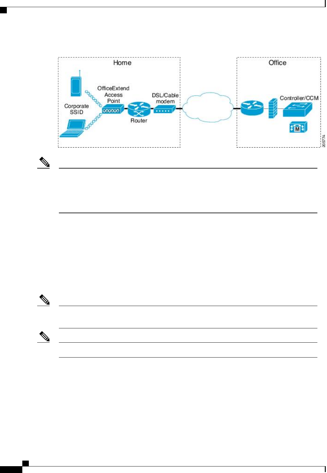
Figure 49: Typical OfficeExtend Access Point Setup
Cisco OEAPs are designed to work behind a router or other gateway device that is using network address
translation (NAT). NAT allows a device, such as a router, to act as an agent between the Internet (public)
and a personal network (private), enabling an entire group of computers to be represented by a single IP
address. There is no limit to the number of Cisco OEAPs that you can deploy behind a NAT device.
Roaming is not supported for the Cisco 600 OEAP model.
Note
Currently, Cisco 1040, 1130, 1140, 2602I, 3502I, and 3600 series access points that are associated with a
controller can be configured to operate as Cisco OEAPs.
OEAP 600 Series Access Points
This section details the requirements for configuring a Cisco wireless LAN controller for use with the Cisco
600 Series OfficeExtend Access Point. The 600 Series OfficeExtend Access Point supports split mode operation,
and it requires configuration through the WLAN controller in local mode. This section describes the
configurations necessary for proper connection and supported feature sets.
The CAPWAP UDP 5246 and 5247 ports must be open on the firewall between the WLAN controller
and the 600 Series OfficeExtend Access Point.
Note
Multicast is not supported on Cisco 600 Series OfficeExtend Access Points.Note
OEAP in Local Mode
The 600 Series OfficeExtend Access Point connects to the controller in local mode. You cannot alter these
settings.
Cisco Wireless LAN Controller Configuration Guide, Release 7.4
734 OL-28744-01
OEAP 600 Series Access Points
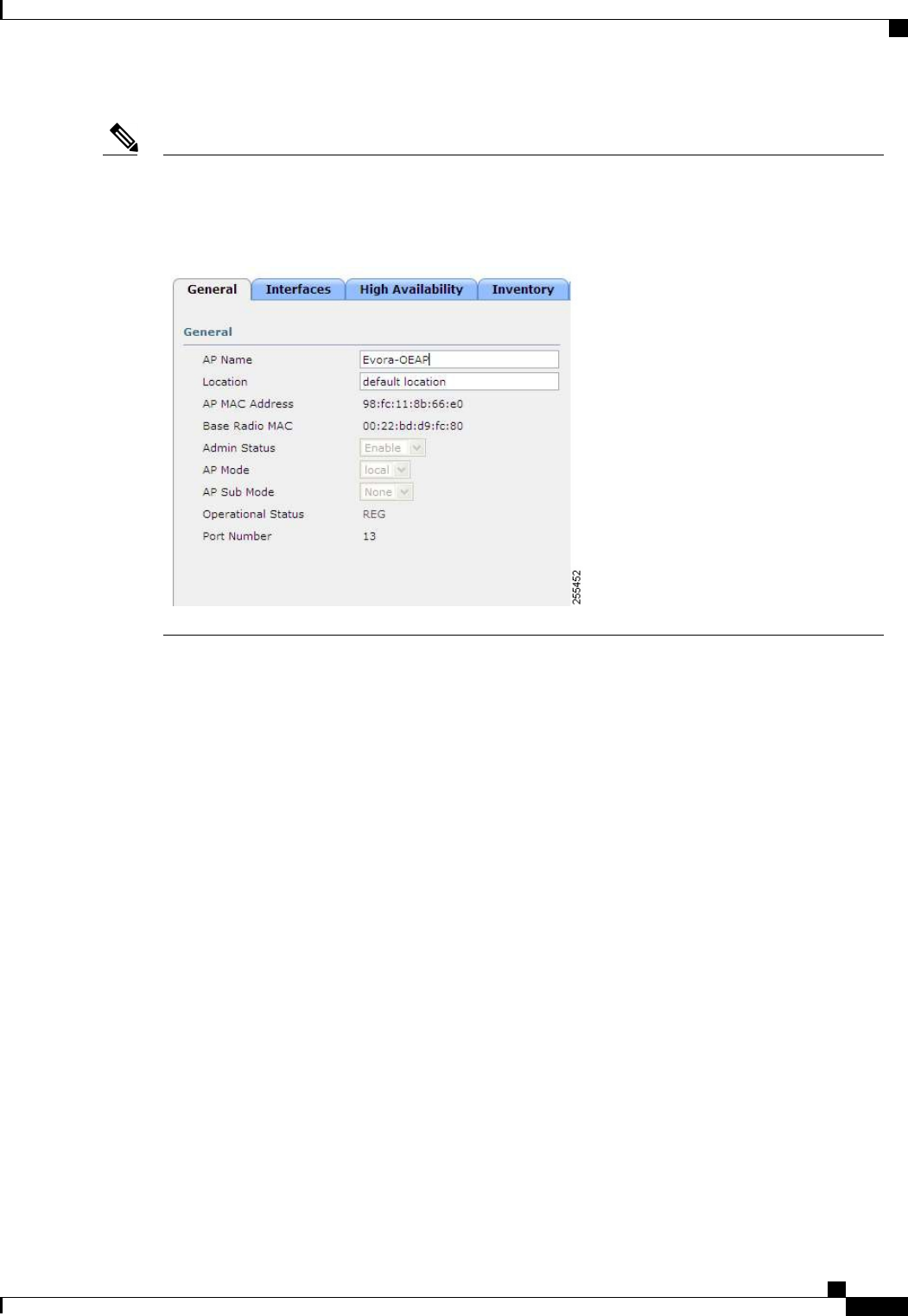
Monitor mode, flexconnect mode, sniffer mode, rogue detector, bridge, and SE-Connect are not supported
on the 600 Series OfficeExtend Access Point and are not configurable.
Figure 50: OEAP Mode
Note
Supported WLAN Settings for 600 Series OfficeExtend Access Point
The 600 Series OfficeExtend Access Point supports a maximum of three WLANs and one remote LAN. If
your network deployment has more than three WLANs, you must place the 600 Series OfficeExtend Access
Point in an AP group. If the 600 Series OfficeExtend Access Points are added to an AP group, the same limit
of three WLANs and one remote LAN still applies for the configuration of the AP group.
If the 600 Series OfficeExtend Access Point is in the default group, which means that it is not in a defined
AP group, the WLAN/remote LAN IDs must be set lower than ID 8.
If additional WLANs or remote LANs are created with the intent of changing the WLANs or remote LAN
being used by the 600 Series OfficeExtend Access Point, you must disable the current WLANs or remote
LAN that you are removing before enabling the new WLANs or remote LAN on the 600 Series OfficeExtend
Access Point. If there are more than one remote LANs enabled for an AP group, disable all remote LANs and
then enable only one of them.
If more than three WLANs are enabled for an AP group, disable all WLANs and then enable only three of
them.
WLAN Security Settings for the 600 Series OfficeExtend Access Point
When configuring the security settings in the WLAN (see the following figure), note that there are specific
elements that are not supported on the 600 Series OfficeExtend Access Point. CCX is not supported on the
600 Series OfficeExtend Access Point, and elements related to CCX are not supported.
For Layer 2 Security, the following options are supported for the 600 Series OfficeExtend Access Point:
Cisco Wireless LAN Controller Configuration Guide, Release 7.4
OL-28744-01 735
OEAP 600 Series Access Points
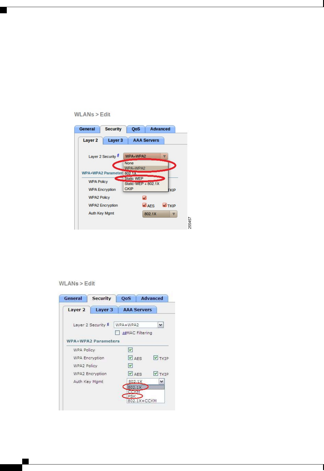
•None
•WPA+WPA2
•Static WEP
•802.1X (only for remote LANs)
Figure 51: WLAN Layer 2 Security Settings
In the Security tab (see the following figure), do not select CCKM in WPA+WPA2 settings. Select only
802.1X or PSK.
Figure 52: WLAN Security Settings - Auth Key Management
Cisco Wireless LAN Controller Configuration Guide, Release 7.4
736 OL-28744-01
OEAP 600 Series Access Points
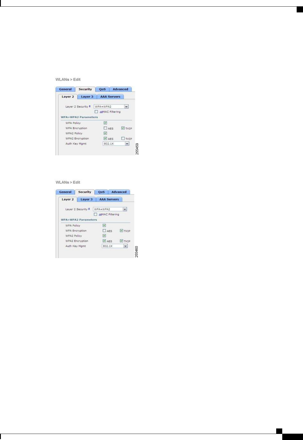
Security encryption settings must be identical for WPA and WPA2 for TKIP and AES. The following are
examples of incompatible settings for TKIP and AES.
Figure 53: Incompatible WPA and WPA2 Security Encryption Settings for OEAP 600 Series
Figure 54: Incompatible WPA and WPA2 Security Encryption Settings for OEAP 600 Series
Cisco Wireless LAN Controller Configuration Guide, Release 7.4
OL-28744-01 737
OEAP 600 Series Access Points
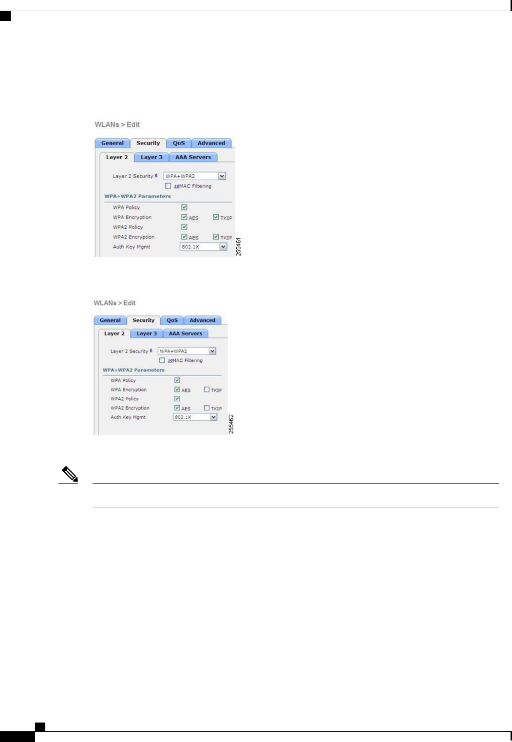
The following are examples of compatible settings:
Figure 55: Compatible Security Settings for OEAP Series
Figure 56: Compatible Security Settings for OEAP Series
QoS settings are supported (see the following figure), but CAC is not supported and should not be enabled.
Do not enable Coverage Hole Detection.Note
Cisco Wireless LAN Controller Configuration Guide, Release 7.4
738 OL-28744-01
OEAP 600 Series Access Points
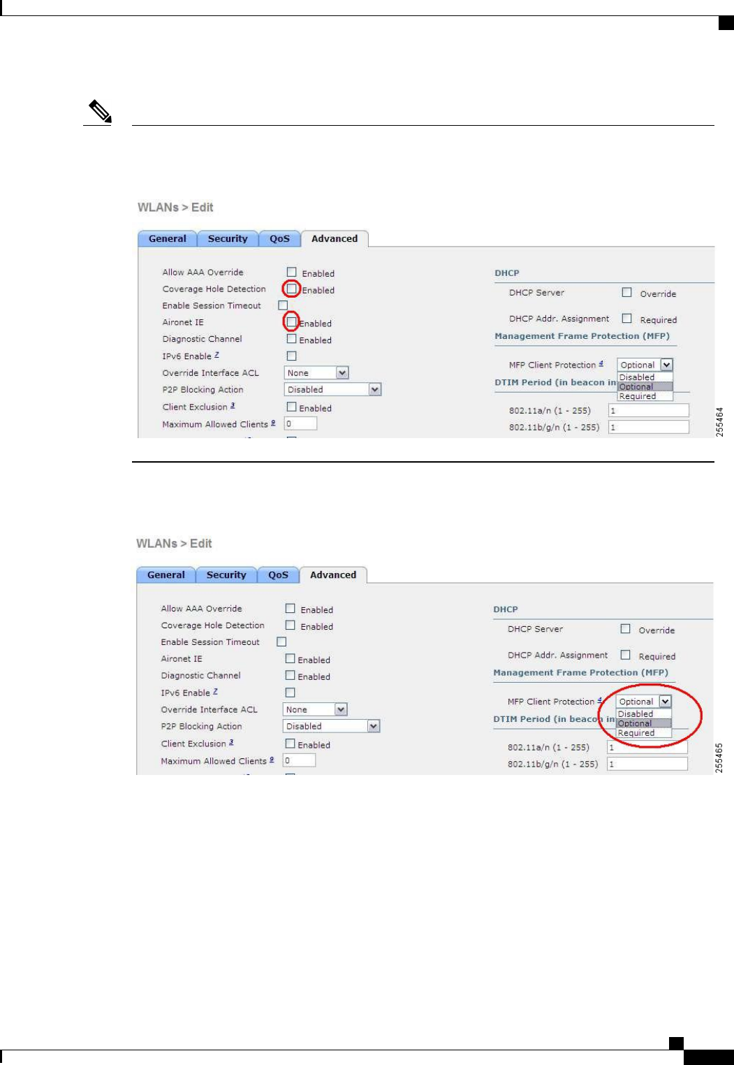
Aironet IE should not be enabled. This option is not supported.
Figure 57: QoS Settings for OEAP 600
Note
MFP is also not supported and should be disabled or set to optional.
Figure 58: MFP Settings for OEAP Series Access Points
Client Load Balancing and Client Band Select are not supported.
Authentication Settings
For authentication on the 600 Series OfficeExtend Access Point, LEAP is not supported. This configuration
must be addressed on the clients and RADIUS servers to migrate them to EAP-Fast, EAP-TTLS, EAP-TLS,
or PEAP.
If Local EAP is being utilized on the controller, the settings would also have to be modified not to use LEAP.
Cisco Wireless LAN Controller Configuration Guide, Release 7.4
OL-28744-01 739
OEAP 600 Series Access Points
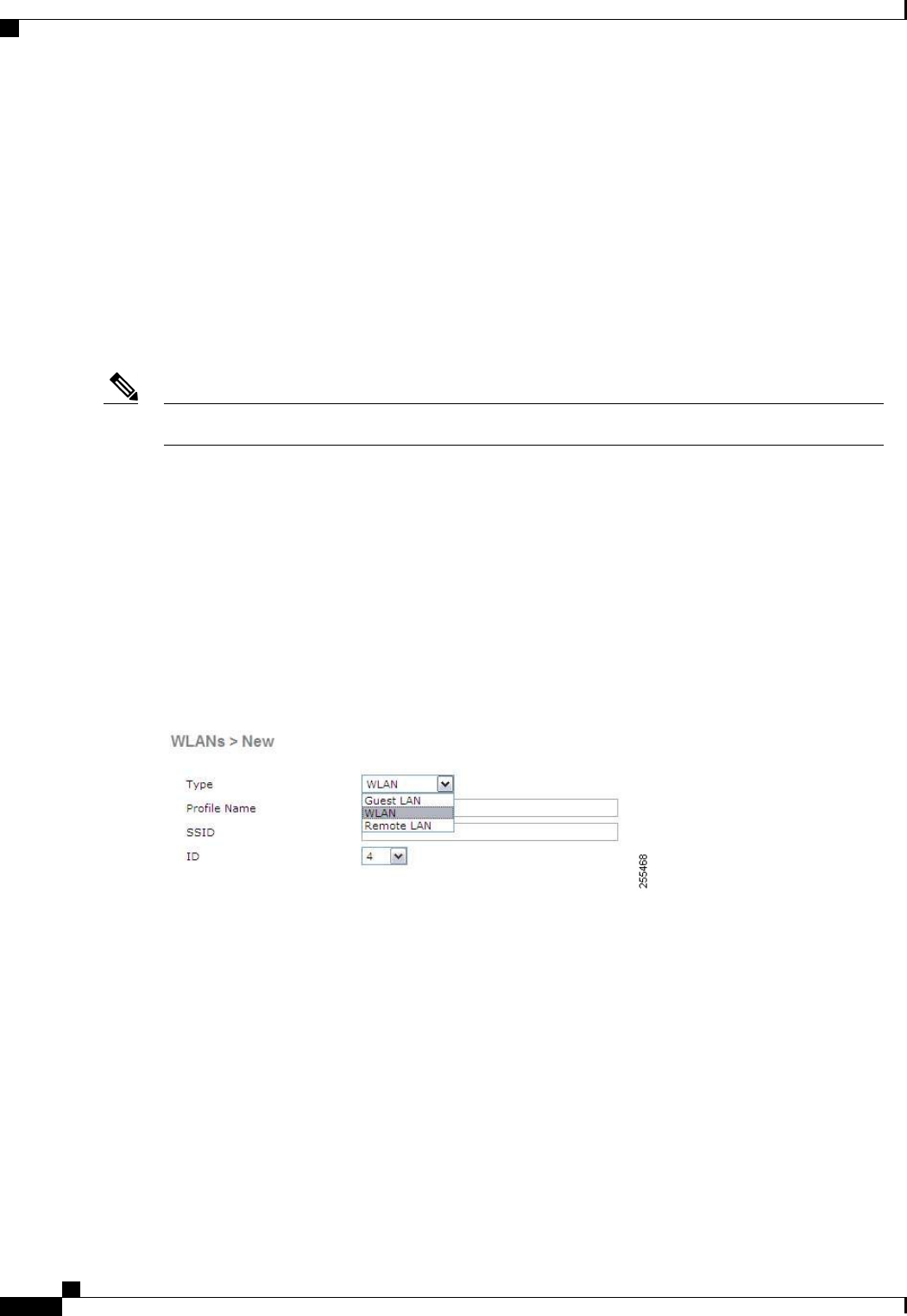
Supported User Count on 600 Series OfficeExtend Access Point
Only 15 users are allowed to connect on the WLANs provided on the Cisco 600 Series OEAP at any one time,
a sixteenth user cannot authenticate until one of the first clients is deauthenticated or timeout on the controller
occurs. This number is cumulative across the controller WLANs on the 600 Series OfficeExtend Access Point.
For example, if two controller WLANs are configured and there are 15 users on one of the WLANs, no other
users can join the other WLAN on the 600 Series OfficeExtend Access Point at that time.
This limit does not apply to the local private WLANs that the end user configures on the 600 Series
OfficeExtend Access Point for personal use. Clients connected on these private WLANs or on the wired ports
do not affect these limits.
This limit does not apply to other AP models that operate in the OfficeExtend mode.Note
Remote LAN Settings
Only four clients can connect through a remote LAN port on the 600 Series OfficeExtend Access Point. This
number does not affect the fifteen user limit imposed for the Controller WLANs. The remote LAN client limit
supports connecting a switch or hub to the remote LAN port for multiple devices or connecting directly to a
Cisco IP phone that is connected to that port. Only the first four devices can connect until one of the devices
is idle for more than one minute.
Remote LAN is configured in the same way that a WLAN or Guest LAN is configured on the controller:
Figure 59: Remote LAN Settings for OEAP 600 Series AP
Cisco Wireless LAN Controller Configuration Guide, Release 7.4
740 OL-28744-01
OEAP 600 Series Access Points
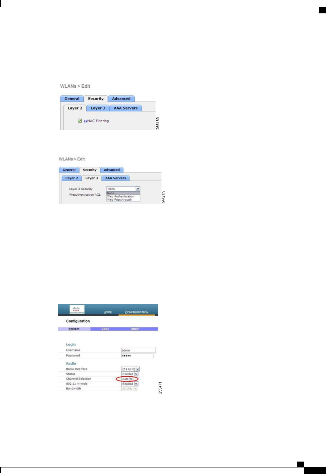
Security settings can be left open, set for MAC filtering, or set for Web Authentication. The default is to use
MAC filtering. Additionally, you can specify 802.1X Layer 2 security settings.
Figure 60: Layer 2 Security Settings for OEAP 600 Series APs in Remote LANs
Figure 61: Layer 3 Security Settings for OEAP 600 Series APs in Remote LANs
Channel Management and Settings
The radios for the 600 Series OfficeExtend Access Point are controlled through the Local GUI on the access
point and not through the Wireless LAN Controller. Attempting to control the spectrum channel or power, or
to disable the radios through the controller does not have effect on the 600 Series OfficeExtend Access Point.
RRM is not supported on the 600 Series OfficeExtend Access Point.
The 600 series scans and chooses channels for 2.4-GHz and 5-GHz during startup as long as the default settings
on the local GUI are left as default in both spectrums.
Figure 62: Channel Selection for OEAP 600 Series APs
Cisco Wireless LAN Controller Configuration Guide, Release 7.4
OL-28744-01 741
OEAP 600 Series Access Points
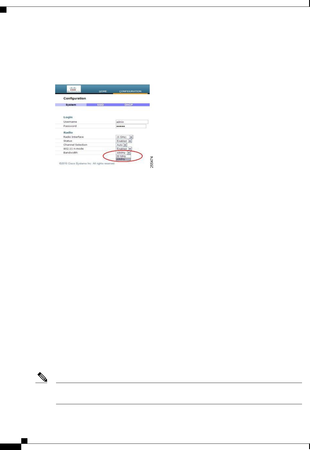
The channel bandwidth for 5.0 GHz is also configured on the 600 Series OfficeExtend Access Point Local
GUI, for 20-MHz or 40-MHz wide channels. Setting the channel width to 40 MHz for 2.4 GHz is not supported
and fixed at 20 MHz.
Figure 63: Channel Width for OEAP 600 APs
Additional Caveats
•The Cisco 600 Series OfficeExtend Access Points (OEAPs) are designed for single AP deployments,
therefore client roaming between Cisco 600 Series OEAPs is not supported.
Disabling the 802.11a/n or 802.11b/g/n on the controller may not disable these spectrums on the Cisco
600 Series OEAP because local SSID may be still working.
•Your firewall must be configured to allow traffic from access points using CAPWAP. Make sure that
UDP ports 5246 and 5247 are enabled and are not blocked by an intermediate device that could prevent
an access point from joining the controller.
•APs such as 3500, 3600, 1260, 2600, and 1040 that are converted to OEAP mode and mapped to locally
switched WLAN forward the DHCP request to the local subnet on the AP connected switch. To avoid
this condition, you must disable local switching and local authentication.
•For Cisco 600 Series OEAP to associate with Cisco Virtual Wireless LAN Controller, follow these steps:
1Configure the OEAP to associate with a physical controller that is using 7.5 or a later release and
download the corresponding AP image.
2Configure the OEAP so that the OEAP does not associate with the physical controller again; for
example, you can implement an ACL in the network to block CAPWAP between the OEAP and the
physical controller.
3Configure the OEAP to associate with the Cisco Virtual Wireless LAN Controller.
Implementing Security
Configuring LSC is not a requirement but is an option. The OfficeExtend 600 access points do not support
LSC.
Note
Cisco Wireless LAN Controller Configuration Guide, Release 7.4
742 OL-28744-01
Implementing Security

1Use local significant certificates (LSCs) to authorize your OfficeExtend access points, by following the
instructions in Authorizing Access Points Using LSCs.
2Implement AAA server validation using the access point’s MAC address, name, or both as the username
in authorization requests, by entering this command:
config auth-list ap-policy authorize-ap username {ap_mac |Cisco_AP |both}
Using the access point name for validation can ensure that only the OfficeExtend access points of valid
employees can associate with the controller. To implement this security policy, ensure that you name each
OfficeExtend access point with an employee ID or employee number. When an employee is terminated,
run a script to remove this user from the AAA server database, which prevents that employee’s OfficeExtend
access point from joining the network.
3Save your changes by entering this command:
save config
CCX is not supported on the 600 OEAP. Elements related to CCX are not supported. Also, only 802.1X
or PSK is supported. TKIP and AES security encryption settings must be identical for WPA and WPA2.
Note
Licensing for an OfficeExtend Access Point
To use OfficeExtend access points, a base license must be installed and in use on the controller. After the
license is installed, you can enable the OfficeExtend mode on the following AP models:
•1130
•1240
•1040
•1140
•1250
•1260
•1600
•2600
•3500 (integrated antenna) series
•3600 (integrated antenna) series
Configuring OfficeExtend Access Points
After the 1130 series, 1140 series, 1040 series, 3500 (integrated antenna) series, or 3600 (integrated antenna)
series access point has joined the controller, you can configure it as an OfficeExtend access point.
Cisco Wireless LAN Controller Configuration Guide, Release 7.4
OL-28744-01 743
Licensing for an OfficeExtend Access Point

Configuring OfficeExtend Access Points (GUI)
Step 1 Choose Wireless to open the All APs page.
Step 2 Click the name of the desired access point to open the All APs > Details page.
Step 3 Enable FlexConnect on the access point as follows:
a) In the General tab, choose FlexConnect from the AP Mode drop-down list to enable FlexConnect for this access
point.
Step 4 Configure one or more controllers for the access point as follows:
a) Click the High Availability tab.
b) Enter the name and IP address of the primary controller for this access point in the Primary Controller Name and
Management IP Address text boxes.
You must enter both the name and IP address of the controller. Otherwise, the access point cannot join this
controller.
Note
c) If desired, enter the name and IP address of a secondary or tertiary controller (or both) in the corresponding Controller
Name and Management IP Address text boxes.
d) Click Apply. The access point reboots and then rejoins the controller.
The names and IP addresses must be unique for the primary, secondary, and tertiary controllers.Note
Step 5 Enable OfficeExtend access point settings as follows:
a) Click the FlexConnect tab.
b) Select the Enable OfficeExtend AP check box to enable the OfficeExtend mode for this access point. The default
value is selected.
Unselecting this check box disables OfficeExtend mode for this access point. It does not undo all of the configuration
settings on the access point. If you want to clear the access point’s configuration and return it to the factory-default
settings, enter clear ap config Cisco_AP on the controller CLI. If you want to clear only the access point’s personal
SSID, click Reset Personal SSID.
Rogue detection is disabled automatically when you enable the OfficeExtend mode for an access point.
However, you can enable or disable rogue detection for a specific access point by selecting the Rogue
Detection check box on the All APs > Details for (Advanced) page. Rogue detection is disabled by default
for OfficeExtend access points because these access points, which are deployed in a home environment, are
likely to detect a large number of rogue devices.
Note
DTLS data encryption is enabled automatically when you enable the OfficeExtend mode for an access point.
However, you can enable or disable DTLS data encryption for a specific access point by selecting the Data
Encryption check box on the All APs > Details for (Advanced) page.
Note
Telnet and SSH access are disabled automatically when you enable the OfficeExtend mode for an access
point. However, you can enable or disable Telnet or SSH access for a specific access point by selecting the
Telnet or SSH check box on the All APs > Details for (Advanced) page.
Note
Link latency is enabled automatically when you enable the OfficeExtend mode for an access point. However,
you can enable or disable link latency for a specific access point by selecting the Enable Link Latency
check box on the All APs > Details for (Advanced) page.
Note
c) Select the Enable Least Latency Controller Join check box if you want the access point to choose the controller
with the least latency when joining. Otherwise, leave this check box unselected, which is the default value. When
you enable this feature, the access point calculates the time between the discovery request and discovery response
and joins the Cisco 5500 Series Controller that responds first.
Cisco Wireless LAN Controller Configuration Guide, Release 7.4
744 OL-28744-01
Configuring OfficeExtend Access Points

d) Click Apply.
The OfficeExtend AP text box on the All APs page shows which access points are configured as OfficeExtend access
points.
Step 6 Configure a specific username and password for the OfficeExtend access point so that the user at home can log into the
GUI of the OfficeExtend access point:
a) Click the Credentials tab.
b) Select the Over-ride Global Credentials check box to prevent this access point from inheriting the global username,
password, and enable password from the controller. The default value is unselected.
c) In the Username,Password, and Enable Password text boxes, enter the unique username, password, and enable
password that you want to assign to this access point.
The information that you enter is retained across controller and access point reboots and if the access point
joins a new controller.
Note
d) Click Apply.
If you want to force this access point to use the controller’s global credentials, unselect the Over-ride Global
Credentials check box.
Note
Step 7 Configure access to local GUI, LAN ports, and local SSID of the OfficeExtend access points:
a) Choose Wireless > Access Points > Global Configuration to open the Global Configuration page.
b) Under OEAP Config Parameters, select or unselect the Disable Local Access check box to enable or disable local
access of the OfficeExtend access points.
By default, the Disable Local Access check box is unselected and therefore the Ethernet ports and personal
SSIDs are enabled. This configuration does not affect remote LAN. The port is enabled only when you
configure a remote LAN.
Note
Step 8 Click Save Configuration.
Step 9 If your controller supports only OfficeExtend access points, see the Configuring RRM section for instructions on setting
the recommended values for the DCA interval, channel scan duration, and neighbor packet frequency.
Configuring OfficeExtend Access Points (CLI)
•Enable FlexConnect on the access point by entering this command:
config ap mode flexconnect Cisco_AP
•Configure one or more controllers for the access point by entering one or all of these commands:
config ap primary-base controller_name Cisco_AP controller_ip_address
config ap secondary-base controller_name Cisco_AP controller_ip_address
config ap tertiary-base controller_name Cisco_AP controller_ip_address
You must enter both the name and IP address of the controller. Otherwise, the access point cannot join
this controller.
Note
Cisco Wireless LAN Controller Configuration Guide, Release 7.4
OL-28744-01 745
Configuring OfficeExtend Access Points

The names and IP addresses must be unique for the primary, secondary, and tertiary controllers.Note
•Enable the OfficeExtend mode for this access point by entering this command:
config flexconnect office-extend {enable |disable}Cisco_AP
The default value is enabled. The disable parameter disables OfficeExtend mode for this access point.
It does not undo all of the configuration settings on the access point. If you want to clear the access
point’s configuration and return it to the factory-default settings, enter this command:
clear ap config cisco-ap
If you want to clear only the access point’s personal SSID, enter this command:
config flexconnect office-extend clear-personalssid-config Cisco_AP.
Rogue detection is disabled automatically when you enable the OfficeExtend mode for an access point.
However, you can enable or disable rogue detection for a specific access point or for all access points
using the config rogue detection {enable |disable} {Cisco_AP |all} command. Rogue detection is
disabled by default for OfficeExtend access points because these access points, which are deployed in a
home environment, are likely to detect a large number of rogue devices.
Note
DTLS data encryption is enabled automatically when you enable the OfficeExtend mode for an access
point. However, you can enable or disable DTLS data encryption for a specific access point or for all
access points using the config ap link-encryption {enable |disable} {Cisco_AP |all} command.
Note
Telnet and SSH access are disabled automatically when you enable the OfficeExtend mode for an access
point. However, you can enable or disable Telnet or SSH access for a specific access point using the config
ap {telnet |ssh} {enable |disable}Cisco_AP command.
Note
Link latency is enabled automatically when you enable the OfficeExtend mode for an access point.
However, you can enable or disable link latency for a specific access point or for all access points currently
associated to the controller using the config ap link-latency {enable |disable} {Cisco_AP |all} command.
Note
•Enable the access point to choose the controller with the least latency when joining by entering this
command:
config flexconnect join min-latency {enable |disable}Cisco_AP
The default value is disabled. When you enable this feature, the access point calculates the time between
the discovery request and discovery response and joins the Cisco 5500 Series Controller that responds
first.
•Configure a specific username and password that users at home can enter to log into the GUI of the
OfficeExtend access point by entering this command:
Cisco Wireless LAN Controller Configuration Guide, Release 7.4
746 OL-28744-01
Configuring OfficeExtend Access Points

config ap mgmtuser add username user password password enablesecret enable_password Cisco_AP
The credentials that you enter in this command are retained across controller and access point reboots
and if the access point joins a new controller.
If you want to force this access point to use the controller’s global credentials, enter the config ap mgmtuser
delete Cisco_AP command. The following message appears after you execute this command: “AP reverted
to global username configuration.”
Note
•To configure access to the local network for the Cisco 600 Series OfficeExtend access points, enter the
following command:
config network oeap-600 local-network {enable |disable}
When disabled, the local SSIDs, local ports are inoperative; and the console is not accessible. When
reset, the default restores local access. This configuration does not affect the remote LAN configuration
if configured on the access points.
•Configure the Dual R-LAN Ports feature, which allows the Ethernet port 3 of Cisco 600 Series
OfficeExtend access points to operate as a remote LAN by entering this command:
config network oeap-600 dual-rlan-ports {enable |disable}
This configuration is global to the controller and is stored by the AP and the NVRAM variable. When
this variable is set, the behavior of the remote LAN is changed. This feature supports different remote
LANs per remote LAN port.
The remote LAN mapping is different depending on whether the default group or AP Groups is used:
•Default Group—If you are using the default group, a single remote LAN with an even numbered
remote LAN ID is mapped to port 4. For example, a remote LAN with remote LAN ID 2 is mapped
to port 4 (on the Cisco 600 OEAP). The remote LAN with an odd numbered remote LAN ID is
mapped to port 3 (on the Cisco 600 OEAP). For example, a remote LAN with remote LAN ID 1
is mapped to port 3 (on the Cisco 600 OEAP).
•AP Groups—If you are using an AP group, the mapping to the OEAP-600 ports is determined by
the order of the AP groups. To use an AP group, you must first delete all remote LANs and WLANs
from the AP group leaving it empty. Then, add the two remote LANs to the AP group adding the
port 3 AP remote LAN first, and the port 4 remote group second, followed by any WLANs.
•Save your changes by entering this command:
save config
If your controller supports only OfficeExtend access points, see the Configuring Radio Resource
Management section for instructions on setting the recommended value for the DCA interval.
Note
Configuring a Personal SSID on an OfficeExtend Access Point
Step 1 Find the IP address of your OfficeExtend access point by doing one of the following:
Cisco Wireless LAN Controller Configuration Guide, Release 7.4
OL-28744-01 747
Configuring a Personal SSID on an OfficeExtend Access Point
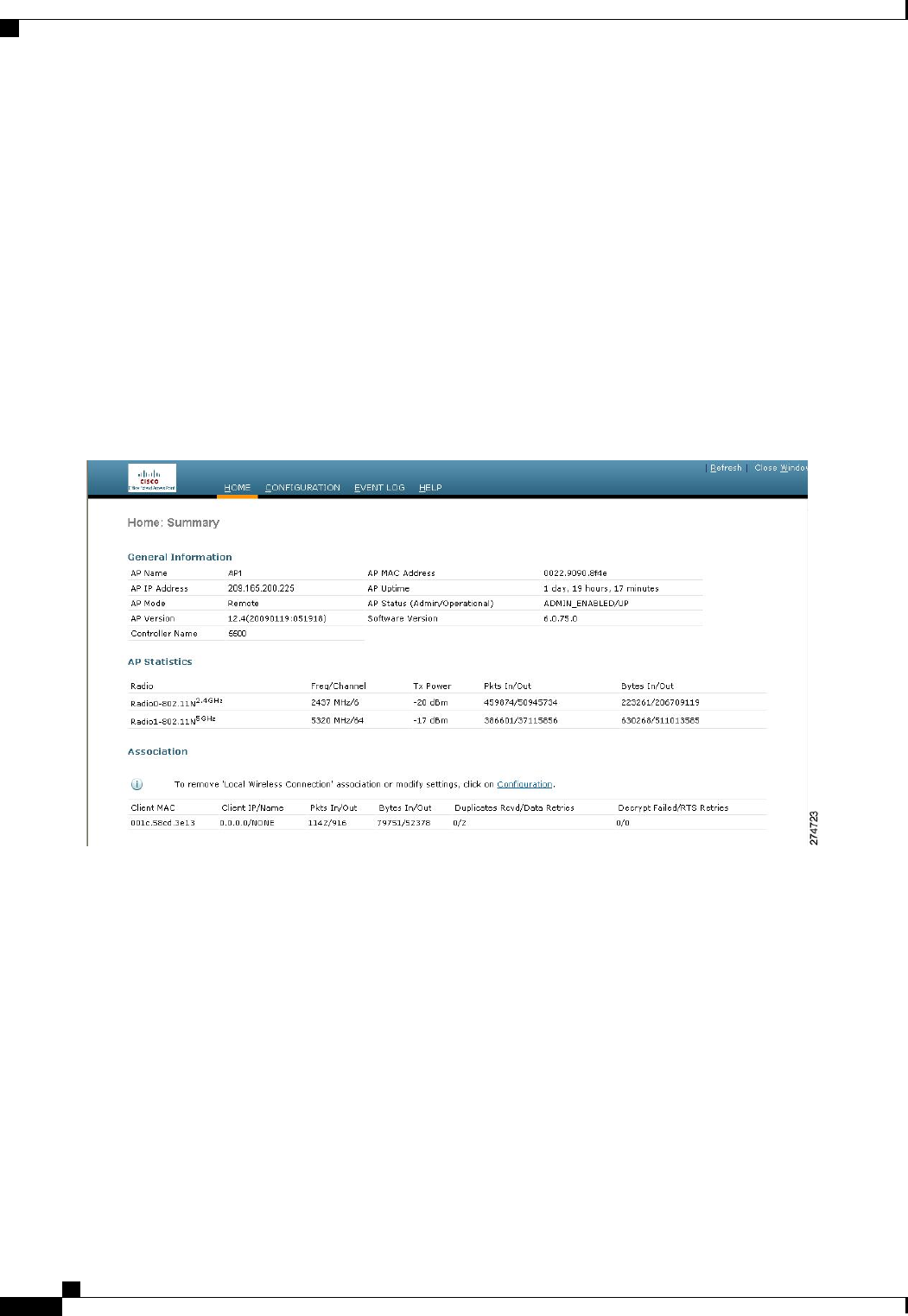
Log on to your home router and look for the IP address of your OfficeExtend access point.
•
•Ask your company’s IT professional for the IP address of your OfficeExtend access point.
•Use an application such as Network Magic to detect devices on your network and their IP addresses.
Step 2 With the OfficeExtend access point connected to your home router, enter the IP address of the OfficeExtend access point
in the Address text box of your Internet browser and click Go.
Make sure that you are not connected to your company’s network using a virtual private network (VPN)
connection.
Note
Step 3 When prompted, enter the username and password to log into the access point.
Step 4 On the OfficeExtend Access Point Welcome page, click Enter. The OfficeExtend Access Point Home page appears.
Figure 64: OfficeExtend Access Point Home Page
This page shows the access point name, IP address, MAC address, software version, status, channel, transmit power,
and client traffic.
Cisco Wireless LAN Controller Configuration Guide, Release 7.4
748 OL-28744-01
Configuring a Personal SSID on an OfficeExtend Access Point
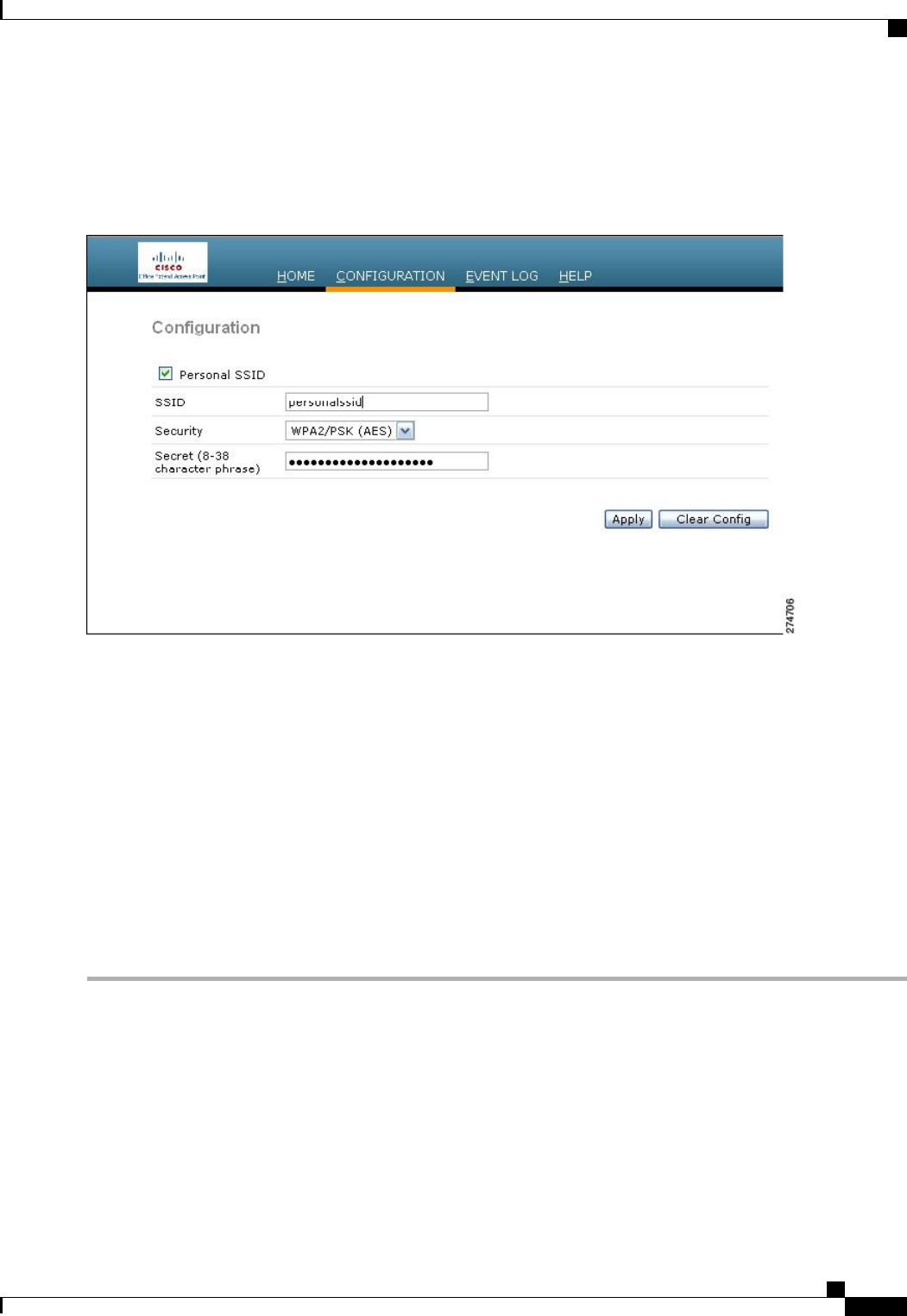
Step 5 Choose Configuration to open the Configuration page.
Figure 65: OfficeExtend Access Point Configuration Page
Step 6 Select the Personal SSID check box to enable this wireless connection. The default value is disabled.
Step 7 In the SSID text box, enter the personal SSID that you want to assign to this access point. This SSID is locally switched.
A controller with an OfficeExtend access point publishes only up to 15 WLANs to each connected access point
because it reserves one WLAN for the personal SSID.
Note
Step 8 From the Security drop-down list, choose Open,WPA2/PSK (AES), or 104 bit WEP to set the security type to be used
by this access point.
If you choose WPA2/PSK (AES), make sure that the client is configured for WPA2/PSK and AES encryption.Note
Step 9 If you chose WPA2/PSK (AES) in Step 8, enter an 8- to 38-character WPA2 passphrase in the Secret text box. If you
chose 104 bit WEP, enter a 13-character ASCII key in the Key text box.
Step 10 Click Apply.
If you want to use the OfficeExtend access point for another application, you can clear this configuration and
return the access point to the factory-default settings by clicking Clear Config. You can also clear the access
point’s configuration from the controller CLI by entering the clear ap config Cisco_AP command.
Note
Viewing OfficeExtend Access Point Statistics
Use these commands to view information about the OfficeExtend access points on your network:
•See a list of all OfficeExtend access points by entering this command:
show flexconnect office-extend summary
Cisco Wireless LAN Controller Configuration Guide, Release 7.4
OL-28744-01 749
Viewing OfficeExtend Access Point Statistics

•See the link delay for OfficeExtend access points by entering this command:
show flexconnect office-extend latency
•See the encryption state of all access points or a specific access point by entering this command:
show ap link-encryption {all |Cisco_AP}
This command also shows authentication errors, which track the number of integrity check failures, and
replay errors, which track the number of times that the access point receives the same packet. See the
data plane status for all access points or a specific access point by entering this command:
show ap data-plane {all |Cisco_AP}
Cisco Wireless LAN Controller Configuration Guide, Release 7.4
750 OL-28744-01
Viewing OfficeExtend Access Point Statistics

CHAPTER 110
Using Cisco Workgroup Bridges
•Information About Cisco Workgroup Bridges, page 751
•Restrictions for Cisco Workgroup Bridges, page 753
•WGB Configuration Example, page 754
•Viewing the Status of Workgroup Bridges (GUI), page 755
•Viewing the Status of Workgroup Bridges (CLI), page 755
•Debugging WGB Issues (CLI), page 756
Information About Cisco Workgroup Bridges
A workgroup bridge (WGB) is a mode that can be configured on an autonomous IOS access point to provide
wireless connectivity to a lightweight access point on behalf of clients that are connected by Ethernet to the
WGB access point. A WGB connects a wired network over a single wireless segment by learning the MAC
addresses of its wired clients on the Ethernet interface and reporting them to the lightweight access point using
Internet Access Point Protocol (IAPP) messaging. The WGB provides wireless access connectivity to wired
clients by establishing a single wireless connection to the lightweight access point. The lightweight access
point treats the WGB as a wireless client.
Cisco Wireless LAN Controller Configuration Guide, Release 7.4
OL-28744-01 751
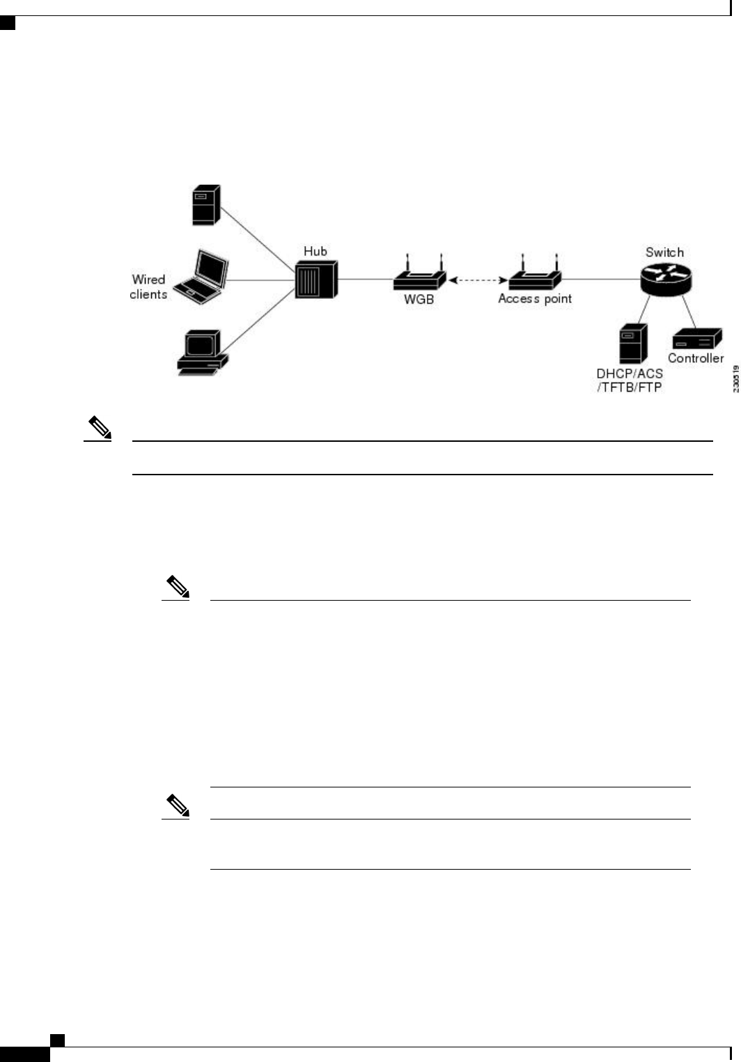
A Cisco IOS AP as a WGB using the Cisco IOS 15.2 or later releases support Protected Extensible
Authentication Protocol (PEAP) with the controller.
Figure 66: WGB Example
If the lightweight access point fails, the WGB attempts to associate to another access point.Note
The following are some guidelines for Cisco Workgroup Bridges:
•The WGB can be any autonomous access point that supports the workgroup bridge mode and is running
Cisco IOS Release 12.4(3g)JA or later releases (on 32-MB access points) or Cisco IOS Release 12.3(8)JEB
or later releases (on 16-MB access points). These access points include the AP1120, AP1121, AP1130,
AP1231, AP1240, and AP1310. Cisco IOS releases prior to 12.4(3g)JA and 12.3(8)JEB are not supported.
If your access point has two radios, you can configure only one for workgroup bridge
mode. This radio is used to connect to the lightweight access point. We recommend that
you disable the second radio.
Enable the workgroup bridge mode on the WGB as follows:
Note
•On the WGB access point GUI, choose Workgroup Bridge for the role in radio
network on the Settings > Network Interfaces page.
•On the WGB access point CLI, enter the station-role workgroup-bridge
command.
See the sample WGB access point configuration in the WGB Configuration Example
section.
Note
•The following features are supported for use with a WGB:
◦Guest N+1 redundancy
◦Local EAP
Cisco Wireless LAN Controller Configuration Guide, Release 7.4
752 OL-28744-01
Information About Cisco Workgroup Bridges

◦Open, WEP 40, WEP 128, CKIP, WPA+TKIP, WPA2+AES, LEAP, EAP-FAST, and EAP-TLS
authentication modes
•Wired clients connected to the WGB are not authenticated for security. Instead, the WGB is authenticated
against the access point to which it associates. Therefore, we recommend that you physically secure the
wired side of the WGB.
•Wired clients connected to a WGB inherit the WGB’s QoS and AAA override attributes.
•To enable the WGB to communicate with the lightweight access point, create a WLAN and make sure
that Aironet IE is enabled.
•If you have to apply ACL to WGB during run time, do not modify the ACL configuration for interface
in the controller during run time. If you need to modify any ACLs, then you must diable all WLANs
that are in the controller or disable both the 802.11a and 80.11b networks. Also, ensure that there are
no clients associated and mapped to that interface and then you can modify the ACL settings.
Restrictions for Cisco Workgroup Bridges
•The WGB can associate only with lightweight access points.
•Only WGBs in client mode (which is the default value) are supported. Those WGBs in infrastructure
mode are not supported. Perform one of the following to enable client mode on the WGB:
◦On the WGB access point GUI, choose Disabled for the Reliable Multicast to WGB parameter.
◦On the WGB access point CLI, enter the no infrastructure client command.
VLANs are not supported for use with WGBs.Note
See the sample WGB access point configuration in the WGB Configuration Example
section.
Note
•The following features are not supported for use with a WGB:
◦Cisco Centralized Key Management (CCKM)
◦Idle timeout
◦Web authentication
If a WGB associates to a web-authentication WLAN, the WGB is added to the exclusion
list, and all of the WGB wired clients are deleted.
Note
•The WGB supports a maximum of 20 wired clients. If you have more than 20 wired clients, use a bridge
or another device.
Cisco Wireless LAN Controller Configuration Guide, Release 7.4
OL-28744-01 753
Restrictions for Cisco Workgroup Bridges

•The DirectStream feature from the controller does not work for clients behind workgroup bridges and
the stream is denied.
•With Layer 3 roaming, if you plug a wired client into the WGB network after the WGB has roamed to
another controller (for example, to a foreign controller), the wired client’s IP address displays only on
the anchor controller, not on the foreign controller.
•If a wired client does not send traffic for an extended period of time, the WGB removes the client from
its bridge table, even if traffic is continuously being sent to the wired client. As a result, the traffic flow
to the wired client fails. To avoid the traffic loss, prevent the wired client from being removed from the
bridge table by configuring the aging-out timer on the WGB to a large value using the following Cisco
IOS commands on the WGB:
configure terminal
bridge bridge-group-number aging-time seconds
exit
end
where bridge-group-number is a value between 1 and 255, and seconds is a value between 10 and
1,000,000 seconds. We recommend configuring the seconds parameter to a value greater than the wired
client’s idle period.
•When you delete a WGB record from the controller, all of the WGB wired clients’records are also
deleted.
•These features are not supported for wired clients connected to a WGB:
◦MAC filtering
◦Link tests
◦Idle timeout
•The broadcast forwarding toward wired WGB clients works only on the native VLAN. If additional
VLANs are configured, only the native VLAN forwards broadcast traffic.
•Wired clients behind a WGB cannot connect to a DMZ/Anchor controller. To enable wired clients behind
a WGB to connect to an anchor controller in a DMZ, you must enable VLANs in the WGB using the
config wgb vlan enable command.
•The dot11 arp-cache global configuration command that you can enter on the access point that is in
WGB mode is not supported.
WGB Configuration Example
The following is an example of the configuration of a WGB access point using static WEP with a 40-bit WEP
key:
ap# configure terminal
Enter configuration commands, one per line. End with CNTL/Z.
ap(config)# dot11 ssid WGB_with_static_WEP
ap(config-ssid)# authentication open
ap(config-ssid)# guest-mode
ap(config-ssid)# exit
ap(config)# interface dot11Radio 0
ap(config)# station-role workgroup-bridge
ap(config-if)# encry mode wep 40
ap(config-if)# encry key 1 size 40 0 1234567890
Cisco Wireless LAN Controller Configuration Guide, Release 7.4
754 OL-28744-01
WGB Configuration Example

ap(config-if)# ssid WGB_with_static_WEP
ap(config-if)# end
Verify that the WGB is associated to an access point by entering this command on the WGB:
show dot11 association
Information similar to the following appears:
ap# show dot11 associations
802.11 Client Stations on Dot11Radio0:
SSID [FCVTESTING] :
MAC Address IP address Device Name Parent State
000b.8581.6aee 10.11.12.1 WGB-client map1 - Assoc
ap#
Viewing the Status of Workgroup Bridges (GUI)
Step 1 Choose Monitor >Clients to open the Clients page.
The WGB text box on the right side of the page indicates whether any of the clients on your network are workgroup
bridges.
Step 2 Click the MAC address of the desired client. The Clients > Detail page appears.
The Client Type text box under Client Properties shows “WGB”if this client is a workgroup bridge, and the Number of
Wired Client(s) text box shows the number of wired clients that are connected to this WGB.
Step 3 See the details of any wired clients that are connected to a particular WGB as follows:
a) Click Back on the Clients > Detail page to return to the Clients page.
b) Hover your cursor over the blue drop-down arrow for the desired WGB and choose Show Wired Clients. The WGB
Wired Clients page appears.
If you want to disable or remove a particular client, hover your cursor over the blue drop-down arrow for
the desired client and choose Remove or Disable, respectively.
Note
c) Click the MAC address of the desired client to see more details for this particular client. The Clients > Detail page
appears.
The Client Type text box under Client Properties shows “WGB Client,”and the rest of the text boxes on this page
provide additional information for this client.
Viewing the Status of Workgroup Bridges (CLI)
Step 1 See any WGBs on your network by entering this command:
show wgb summary
Step 2 See the details of any wired clients that are connected to a particular WGB by entering this command:
show wgb detail wgb_mac_address
Cisco Wireless LAN Controller Configuration Guide, Release 7.4
OL-28744-01 755
Viewing the Status of Workgroup Bridges (GUI)

Debugging WGB Issues (CLI)
Before You Begin
•Enable debugging for IAPP messages, errors, and packets by entering these commands:
◦debug iapp all enable—Enables debugging for IAPP messages.
◦debug iapp error enable—Enables debugging for IAPP error events.
◦debug iapp packet enable—Enables debugging for IAPP packets.
•Debug an roaming issue by entering this command:
debug mobility handoff enable
•Debug an IP assignment issue when DHCP is used by entering these commands:
◦debug dhcp message enable
◦debug dhcp packet enable
•Debug an IP assignment issue when static IP is used by entering these commands:
◦debug dot11 mobile enable
◦debug dot11 state enable
Cisco Wireless LAN Controller Configuration Guide, Release 7.4
756 OL-28744-01
Debugging WGB Issues (CLI)

CHAPTER 111
Using Non-Cisco Workgroup Bridges
•Information About Non-Cisco Workgroup Bridges, page 757
•Restrictions for Non-Cisco Workgroup Bridges, page 758
Information About Non-Cisco Workgroup Bridges
When a Cisco workgroup bridge (WGB) is used, the WGB informs the access points of all the clients that it
is associated with. The controller is aware of the clients associated with the access point. When non-Cisco
WGBs are used, the controller has no information about the IP address of the clients on the wired segment
behind the WGB. Without this information, the controller drops the following types of messages:
•ARP REQ from the distribution system for the WGB client
•ARP RPLY from the WGB client
•DHCP REQ from the WGB client
•DHCP RPLY for the WGB client
The following are some guidelines for Non-Cisco workgroup bridges:
•The controller can accommodate non-Cisco WGBs so that the controller can forward ARP, DHCP, and
data traffic to and from the wired clients behind workgroup bridges by enabling the passive client feature.
To configure your controller to work with non-Cisco WGBs, you must enable the passive client feature
so that all traffic from the wired clients is routed through the WGB to the access point. All traffic from
the wired clients is routed through the work group bridge to the access point.
•When a WGB wired client leaves a multicast group, the downstream multicast traffic to other WGB
wired clients is interrupted briefly.
•If you have clients that use PC virtualization software like VMware, you must enable this feature.
We have tested multiple third-party devices for compatibility but cannot ensure that all
non-Cisco devices work. Support for any interaction or configuration details on the
third-party device should be discussed with the device manufacturer.
Note
Cisco Wireless LAN Controller Configuration Guide, Release 7.4
OL-28744-01 757

•You must enable the passive client functionality for all non-Cisco workgroup bridges.
•You might need to use the following commands to configure DHCP on clients:
◦Disable DHCP proxy by using the config dhcp proxy disable command.
◦Enable DHCP boot broadcast by using the tconfig dhcp proxy disable bootp-broadcast enable
command.
Restrictions for Non-Cisco Workgroup Bridges
•Only Layer 2 roaming is supported for WGB devices.
•Layer 3 security (web authentication) is not support for WGB clients.
•Visibility of wired hosts behind a WGB on a controller is not supported because the non-Cisco WGB
device performs MAC hiding. Cisco WGB supports IAPP.
•ARP poisoning detection does not work on a WLAN when the flag is enabled.
•VLAN select is not supported for WGB clients.
•Some third-party WGBs need to operate in non-DHCP relay mode. If problems occur with the DHCP
assignment on devices behind the non-Cisco WGB, use the config dhcp proxy disable and config dhcp
proxy disable bootp-broadcast disable commands.
The default state is DHCP proxy enabled. The best combination depends on the third-party characteristics
and configuration.
Cisco Wireless LAN Controller Configuration Guide, Release 7.4
758 OL-28744-01
Restrictions for Non-Cisco Workgroup Bridges

CHAPTER 112
Configuring Backup Controllers
•Information About Configuring Backup Controllers, page 759
•Restrictions for Configuring Backup Controllers, page 760
•Configuring Backup Controllers (GUI), page 760
•Configuring Backup Controllers (CLI), page 761
Information About Configuring Backup Controllers
A single controller at a centralized location can act as a backup for access points when they lose connectivity
with the primary controller in the local region. Centralized and regional controllers do not need to be in the
same mobility group. You can specify a primary, secondary, and tertiary controller for specific access points
in your network. Using the controller GUI or CLI, you can specify the IP addresses of the backup controllers,
which allows the access points to fail over to controllers outside of the mobility group.
The following are some guidelines for configuring backup controllers:
•You can configure primary and secondary backup controllers (which are used if primary, secondary, or
tertiary controllers are not specified or are not responsive) for all access points connected to the controller
as well as various timers, including heartbeat timers and discovery request timers. To reduce the controller
failure detection time, you can configure the fast heartbeat interval (between the controller and the access
point) with a smaller timeout value. When the fast heartbeat timer expires (at every heartbeat interval),
the access point determines if any data packets have been received from the controller within the last
interval. If no packets have been received, the access point sends a fast echo request to the controller.
•The access point maintains a list of backup controllers and periodically sends primary discovery requests
to each entry on the list. When the access point receives a new discovery response from a controller, the
backup controller list is updated. Any controller that fails to respond to two consecutive primary discovery
requests is removed from the list. If the access point’s local controller fails, it chooses an available
controller from the backup controller list in this order: primary, secondary, tertiary, primary backup,
and secondary backup. The access point waits for a discovery response from the first available controller
in the backup list and joins the controller if it receives a response within the time configured for the
primary discovery request timer. If the time limit is reached, the access point assumes that the controller
cannot be joined and waits for a discovery response from the next available controller in the list.
•When an access point's primary controller comes back online, the access point disassociates from the
backup controller and reconnects to its primary controller. The access point falls back only to its primary
Cisco Wireless LAN Controller Configuration Guide, Release 7.4
OL-28744-01 759

controller and not to any available secondary controller for which it is configured. For example, if an
access point is configured with primary, secondary, and tertiary controllers, it fails over to the tertiary
controller when the primary and secondary controllers become unresponsive. If the secondary controller
comes back online while the primary controller is down, the access point does not fall back to the
secondary controller and stays connected to the tertiary controller. The access point waits until the
primary controller comes back online to fall back from the tertiary controller to the primary controller.
If the tertiary controller fails and the primary controller is still down, the access point then falls back to
the available secondary controller.
Restrictions for Configuring Backup Controllers
•You can configure the fast heartbeat timer only for access points in local and FlexConnect modes.
Configuring Backup Controllers (GUI)
Step 1 Choose Wireless >Access Points >Global Configuration to open the Global Configuration page.
Step 2 From the Local Mode AP Fast Heartbeat Timer State drop-down list, choose Enable to enable the fast heartbeat timer
for access points in local mode or choose Disable to disable this timer. The default value is Disable.
Step 3 If you chose Enable in Step 2, enter the Local Mode AP Fast Heartbeat Timeout text box to configure the fast heartbeat
timer for access points in local mode. Specifying a small heartbeat interval reduces the amount of time it takes to detect
a controller failure.
The range for the AP Fast Heartbeat Timeout value for Cisco Flex 7500 Controllers is 10–15 (inclusive) and is 1–10
(inclusive) for other controllers. The default value for the heartbeat timeout for Cisco Flex 7500 Controllers is 10. The
default value for other controllers is 1 second.
Step 4 .From the FlexConnect Mode AP Fast Heartbeat Timer State drop-down list, choose Enable to enable the fast heartbeat
timer for FlexConnect access points or choose Disable to disable this timer. The default value is Disable.
Step 5 If you enable FlexConnect fast heartbeat, enter the FlexConnect Mode AP Fast Heartbeat Timeout value in the FlexConnect
Mode AP Fast Heartbeat Timeout text box. Specifying a small heartbeat interval reduces the amount of time it takes to
detect a controller failure.
The range for the FlexConnect Mode AP Fast Heartbeat Timeout value for Cisco Flex 7500 Controllers is 10–15 (inclusive)
and is 1–10 for other controllers. The default value for the heartbeat timeout for Cisco Flex 7500 Controllers is 10. The
default value for other controllers is 1 second.
Step 6 In the AP Primary Discovery Timeout text box, a value between 30 and 3600 seconds (inclusive) to configure the access
point primary discovery request timer. The default value is 120 seconds.
Step 7 If you want to specify a primary backup controller for all access points, enter the IP address of the primary backup
controller in the Back-up Primary Controller IP Address text box and the name of the controller in the Back-up Primary
Controller Name text box.
The default value for the IP address is 0.0.0.0, which disables the primary backup controller.Note
Step 8 If you want to specify a secondary backup controller for all access points, enter the IP address of the secondary backup
controller in the Back-up Secondary Controller IP Address text box and the name of the controller in the Back-up
Secondary Controller Name text box.
The default value for the IP address is 0.0.0.0, which disables the secondary backup controller.Note
Cisco Wireless LAN Controller Configuration Guide, Release 7.4
760 OL-28744-01
Restrictions for Configuring Backup Controllers

Step 9 Click Apply to commit your changes.
Step 10 Configure primary, secondary, and tertiary backup controllers for a specific access point as follows:
a) Choose Access Points >All APs to open the All APs page.
b) Click the name of the access point for which you want to configure primary, secondary, and tertiary backup controllers.
c) Choose the High Availability tab to open the All APs > Details for (High Availability) page.
d) If desired, enter the name and IP address of the primary controller for this access point in the Primary Controller text
boxes.
Entering an IP address for the backup controller is optional in this step and the next two steps. If the backup
controller is outside the mobility group to which the access point is connected (the primary controller), then
you need to provide the IP address of the primary, secondary, or tertiary controller, respectively. The controller
name and IP address must belong to the same primary, secondary, or tertiary controller. Otherwise, the
access point cannot join the backup controller.
Note
e) If desired, enter the name and IP address of the secondary controller for this access point in the Secondary Controller
text boxes.
f) If desired, enter the name and IP address of the tertiary controller for this access point in the Tertiary Controller text
boxes.
g) Click Apply to commit your changes.
Step 11 Click Save Configuration to save your changes.
Configuring Backup Controllers (CLI)
Step 1 Configure a primary controller for a specific access point by entering this command:
config ap primary-base controller_name Cisco_AP [controller_ip_address]
The controller_ip_address parameter in this command and the next two commands is optional. If the backup
controller is outside the mobility group to which the access point is connected (the primary controller), then
you need to provide the IP address of the primary, secondary, or tertiary controller, respectively. In each
command, the controller_name and controller_ip_address must belong to the same primary, secondary, or
tertiary controller. Otherwise, the access point cannot join the backup controller.
Note
Step 2 Configure a secondary controller for a specific access point by entering this command:
config ap secondary-base controller_name Cisco_AP [controller_ip_address]
Step 3 Configure a tertiary controller for a specific access point by entering this command:
config ap tertiary-base controller_name Cisco_AP [controller_ip_address]
Step 4 Configure a primary backup controller for all access points by entering this command:
config advanced backup-controller primary backup_controller_name backup_controller_ip_address
Step 5 Configure a secondary backup controller for all access points by entering this command:
config advanced backup-controller secondary backup_controller_name backup_controller_ip_address
To delete a primary or secondary backup controller entry, enter 0.0.0.0 for the controller IP address.
Note
Step 6 Enable or disable the fast heartbeat timer for local or FlexConnect access points by entering this command:
config advanced timers ap-fast-heartbeat {local |flexconnect |all} {enable | disable}interval
Cisco Wireless LAN Controller Configuration Guide, Release 7.4
OL-28744-01 761
Configuring Backup Controllers (CLI)

where all is both local and FlexConnect access points, and interval is a value between 1 and 10 seconds (inclusive).
Specifying a small heartbeat interval reduces the amount of time that it takes to detect a controller failure. The default
value is disabled.Configure the access point heartbeat timer by entering this command:
config advanced timers ap-heartbeat-timeout interval
where interval is a value between 1 and 30 seconds (inclusive). This value should be at least three times larger than the
fast heartbeat timer. The default value is 30 seconds.
Do not enable the fast heartbeat timer with the high latency link. If you have to enable the fast heartbeat timer,
the timer value must be greater than the latency.
Caution
Step 7 Configure the access point primary discovery request timer by entering this command:
config advanced timers ap-primary-discovery-timeout interval
where interval is a value between 30 and 3600 seconds. The default value is 120 seconds.
Step 8 Configure the access point discovery timer by entering this command:
config advanced timers ap-discovery-timeout interval
where interval is a value between 1 and 10 seconds (inclusive). The default value is 10 seconds.
Step 9 Configure the 802.11 authentication response timer by entering this command:
config advanced timers auth-timeout interval
where interval is a value between 10 and 600 seconds (inclusive). The default value is 10 seconds.
Step 10 Save your changes by entering this command:
save config
Step 11 See an access point’s configuration by entering these commands:
•show ap config general Cisco_AP
•show advanced backup-controller
•show advanced timers
Information similar to the following appears for the show ap config general Cisco_AP command:
Cisco AP Identifier.............................. 1
Cisco AP Name.................................... AP5
Country code..................................... US - United States
Regulatory Domain allowed by Country............. 802.11bg:-AB 802.11a:-AB
AP Country code.................................. US - United States
AP Regulatory Domain............................. 802.11bg:-A 802.11a:-N
Switch Port Number .............................. 1
MAC Address...................................... 00:13:80:60:48:3e
IP Address Configuration......................... DHCP
IP Address....................................... 1.100.163.133
...
Primary Cisco Switch Name........................ 1-5508
Primary Cisco Switch IP Address.................. 2.2.2.2
Secondary Cisco Switch Name...................... 1-4404
Secondary Cisco Switch IP Address................ 2.2.2.2
Tertiary Cisco Switch Name....................... 2-4404
Tertiary Cisco Switch IP Address................. 1.1.1.4
Cisco Wireless LAN Controller Configuration Guide, Release 7.4
762 OL-28744-01
Configuring Backup Controllers (CLI)

...
Information similar to the following appears for the show advanced backup-controller command:
AP primary Backup Controller .................... controller1 10.10.10.10
AP secondary Backup Controller ............... 0.0.0.0
Information similar to the following appears for the show advanced timers command:
Authentication Response Timeout (seconds)........ 10
Rogue Entry Timeout (seconds).................... 1300
AP Heart Beat Timeout (seconds).................. 30
AP Discovery Timeout (seconds)................... 10
AP Local mode Fast Heartbeat (seconds)........... 10 (enable)
AP flexconnect mode Fast Heartbeat (seconds)........... disable
AP Primary Discovery Timeout (seconds)........... 120
Cisco Wireless LAN Controller Configuration Guide, Release 7.4
OL-28744-01 763
Configuring Backup Controllers (CLI)

Cisco Wireless LAN Controller Configuration Guide, Release 7.4
764 OL-28744-01
Configuring Backup Controllers (CLI)

CHAPTER 113
Configuring High Availability
•Information About High Availability, page 765
•Restrictions for High Availability, page 767
•Configuring High Availability (GUI), page 769
•Configuring High Availability (CLI), page 770
Information About High Availability
High availability (HA) in controllers allows you to reduce the downtime of the wireless networks that occurs
due to the failover of controllers.
A 1:1 (Active:Standby-Hot) stateful switchover of access points (AP SSO) is supported. In an HA architecture,
one controller is configured as the primary controller and another controller as the secondary controller.
After you enable HA, the primary and secondary controllers are rebooted. During the boot process, the role
of the primary controller is negotiated as active and the role of the secondary controller as standby-hot. After
a switchover, the secondary controller becomes the active controller and the primary controller becomes the
standby-hot controller. After subsequent switchovers, the roles are interchanged between the primary and the
secondary controllers. The reason for switchovers are either because of manual trigger or a controller or
network failure.
During an AP SSO, all the AP sessions statefully switch over and all the clients are deauthenticated and
reassociated with the new active controller except for the locally switched clients in the FlexConnect mode.
The standby-hot controller continuously monitors the health of the active controller through a direct wired
connection over a dedicated redundancy port. Both the controllers share the same configurations, including
the IP address of the management interface.
Before you enable HA, ensure that both the controllers are physically connected through the redundant port
using an Ethernet cable. Also, ensure that the uplink is connected to an infrastructure switch and that the
gateway is reachable from both the controllers.
In HA architecture, the redundancy port and redundant management interfaces have been newly introduced.
The following are some guidelines for high availability:
•We recommend that you do not pair two controllers of different hardware models. If they are paired,
then a higher controller model becomes the active controller and the other controller goes into maintenance
mode.
Cisco Wireless LAN Controller Configuration Guide, Release 7.4
OL-28744-01 765

•We recommend that you do not pair two controllers on different controller software releases. If they are
paired, then the controller with the lower redundancy management address becomes the active controller
and the other controller goes into maintenance mode.
•All download file types, such as Image, Config, Web-Authentication bundle, and Signature files, are
downloaded on the active controller first and then pushed to the standby-hot controller.
•Certificates should be downloaded separately on each controller before they are paired.
•You can upload file types such as Config, Event Logs, Crash files, and so on, from the standby-hot
controller using the GUI or CLI of the active controller. You can also specify a suffix to the filename
to identify the uploaded file.
•To perform a peer upload, use the service port. In a management network, you can also use the redundancy
management interface (RMI) that is mapped to the redundancy port or RMI VLAN, or both, that is the
same as the management VLAN.
•If the controllers cannot reach each other through the redundant port or the RMI, the primary controller
becomes active and the standby-hot controller goes into the maintenance mode.
To achieve HA between two Cisco WiSM2 platforms, the controllers should be deployed
on a single chassis or on multiple chassis using a virtual switching system (VSS) and
extending a redundancy VLAN between the multiple chassis.
Note
A redundancy VLAN should be a nonroutable VLAN in which a Layer 3 interface
should not be created for the VLAN and the interface should be allowed on the trunk
port to extend an HA setup between multiple chassis. Redundancy VLAN should be
created like any other data VLAN on Cisco IOS-based switching software. A redundancy
VLAN is connected to the redundant port on Cisco WiSM2 through the backplane. It
is not necessary to configure the IP address for the redundancy VLAN because the IP
address is automatically generated. Also, ensure that the redundancy VLAN is not the
same as the management VLAN.
Note
•When HA is enabled, ensure that you do not use the backed-up image. If this image is used, the HA
feature might not work as expected:
•The service port and route information that is configured is lost after you enable SSO. You must
configure the service port and route information again after you enable SSO. You can configure
the service port and route information for the standby-hot controller using the peer-service-port
and peer-route commands.
•For Cisco WiSM2, service port reconfigurations are required after you enable redundancy.
Otherwise, Cisco WiSM2 might not be able to communicate with the supervisor. We recommend
that you enable DHCP on the service port before you enable redundancy.
•We recommend that you do not use the reset command on the standby-hot controller directly. If
you use this, unsaved configurations will be lost.
•We recommend that you enable link aggregation (LAG) configuration on the controllers before you
enable the port channel in the infrastructure switches.
Cisco Wireless LAN Controller Configuration Guide, Release 7.4
766 OL-28744-01
Information About High Availability

•All configurations that require reboot of the active controller results in the reboot of the standby-hot
controller.
•The Ignore AP list is not synchronized from the active controller to the standby-hot controller. The list
is relearned through SNMP messages from the Cisco Prime Infrastructure, after the standby-hot controller
becomes active.
•In Release 7.3.x, AP SSO is supported but client SSO is not supported, which means that after an HA
setup that uses Release 7.3.x encounters a switchover, all the clients associated with the Cisco WLC are
deauthenticated and are forced to reassociate.
•You must manually configure the mobility MAC address on the then active controller post switchover,
when a peer controller has a controller software release that is prior to Release 7.2.
Redundancy Management Interface
The active and standby-hot controllers use the Redundancy Management Interface to check the health of the
peer controller and the default gateway of the management interface through the network infrastructure.
The Redundancy Management Interface is also used to send notifications from the active controller to the
standby-hot controller if a failure or manual reset occurs. The standby-hot controller uses the Redundancy
Management Interface to communicate to the syslog, NTP server, FTP, and TFTP server.
It is mandatory to configure the IP addresses of the Redundancy Management Interface and the Management
Interface in the same subnet on both the primary and secondary controllers.
Redundancy Port
The redundancy port is used for configuration, operational data synchronization, and role negotiation between
the primary and secondary controllers.
The redundancy port checks for peer reachability by sending UDP keepalive messages every 100 milliseconds
(default frequency) from the standby-hot controller to the active controller. If a failure of the active controller
occurs, the redundancy port is used to notify the standby-hot controller.
If an NTP server is not configured, the redundancy port performs a time synchronization from the active
controller to the standby-hot controller.
In Cisco WiSM2, the redundancy VLAN must be configured on the Cisco Catalyst 6000 supervisor engine
because there is no physical redundancy port is available on Cisco WiSM2.
The redundancy port and the redundancy VLAN in Cisco WiSM2 are assigned an automatically generated
IP address in which the last two octets are obtained from the last two octets of the Redundancy Management
Interface. The first two octets are always 169.254. For example, if the IP address of the Redundancy
Management Interface is 209.165.200.225, the IP address of the redundancy port is 169.254.200.225.
Restrictions for High Availability
•When you configure the controller for HA SSO, the Cisco 600 Series OfficeExtend Access Points are
not supported.
•In an HA environment using FlexConnect locally switched clients, the client information might not show
the username. To get details about the client, you must use the MAC address of the client. This restriction
does not apply to FlexConnect centrally switched clients or central (local) mode clients.
Cisco Wireless LAN Controller Configuration Guide, Release 7.4
OL-28744-01 767
Restrictions for High Availability

•It is not possible to access the Cisco WiSM2 GUI through the service interface when you have enabled
HA. The workaround is to create a service port interface again after HA is established.
•In an HA environment, an upgrade from an LDPE image to a non-LDPE image is not supported.
•It is not possible to pair two primary controllers or two secondary controllers.
•Standby controllers are unavailable on the APs connected switch port
•An HA-SKU controller with an evaluation license cannot become a standby controller. However, an
HA-SKU controller with zero license can become a standby controller.
•The following scenario is not supported: The primary controller has the management address and the
redundancy management address in the same VLAN, and the secondary controller has the management
address in the same VLAN as the primary one, and the redundancy management address in a different
VLAN.
•The following is a list of some software upgrade scenarios:
•A software upgrade on the active controller ensures the upgrade of the standby-hot controller.
•An in-service upgrade is not supported. Therefore, you should plan your network downtime before
you upgrade the controllers in an HA environment.
•Rebooting the active controller after a software upgrade also reboots the standby-hot controller.
•If both active and standby-hot controllers have different software releases in the backup, and if
you enter the config boot backup command in the active controller, both the controllers reboot
with their respective backup images breaking the HA pair due to a software mismatch.
•A schedule reset applies to both the controllers in an HA environment. The peer controller reboots
a minute before the scheduled time expires on the active controller.
•You can reboot the standby-hot controller from the active controller by entering the reset
peer-system command if the scheduled reset is not planned. If you reset only the standby-hot
controller with this command, any unsaved configurations on the standby-hot controller is lost.
Therefore, ensure that you save the configurations on the active controller before you reset the
standby-hot controller.
•A preimage download is reinitiated if an SSO is triggered at the time of the image transfer.
•Only debug and show commands are allowed on the standby-hot controller.
•It is not possible to access the standby-hot controller through the controller GUI, Cisco Prime
Infrastructure, or Telnet. You can access the standby-hot controller only on its console.
•To enable or disable LAG, you must disable HA.
If LAG is disabled and both primary and backup ports are connected to the management
interface and if the primary port becomes nonoperational, a switchover might occur
because the default gateway is not reachable and backup port failover might exceed 12
seconds.
Note
•When a failover occurs and the standby controller becomes the new active controller, it takes
approximately 15 to 20 minutes to synchronize the database (AP, client, and multicast) between the two
controllers. If another failover occurs during this time, the HA structures would not yet be synchronized.
Therefore, the APs and clients would have to get reassociated and reauthenticated respectively.
Cisco Wireless LAN Controller Configuration Guide, Release 7.4
768 OL-28744-01
Restrictions for High Availability

•Pairwise Master Key (PMK) cache synchronization is not supported on FlexConnect local-authenticated
clients.
•You cannot change the NAT address configuration of the management interface when the controllers
are in redundancy mode. To enable NAT address configuration on the management interface, you must
remove the redundancy configuration first, make the required changes on the primary controller, and
then reenable the redundancy configuration on the same controller.
Configuring High Availability (GUI)
Before You Begin
Ensure that the management interfaces of both controllers are in the same subnet. You can verify this on the
GUI of both the controllers by choosing Controllers > Interfaces and viewing the IP addresses of the
management interface.
Step 1 On the GUI of both controllers, choose Controller > Redundancy > Global Configuration.
The Global Configuration page is displayed.
Step 2 Enter the addresses of both the controllers in the Redundant Management IP and the Peer Redundant Management
IP text boxes.
Ensure that the Redundant Management Interface IP address of one controller is the same as the Redundancy Management
Interface IP address of the peer controller.
Step 3 From the Redundant Unit drop-down list, choose one of the controllers as primary and the other as secondary.
Step 4 On the GUI of both the controllers, set the SSO to Enabled state.
After you enable an SSO, the service port peer IP address and the service port netmask appear on the configuration page.
Note that the service port peer IP address and the netmask can be pushed to the peer only if the HA peer is available and
operational. When you enable HA, you do not have to configure the service port peer IP address and the service port
netmask parameters. You must configure the parameters only when the HA peer is available and operational. After you
enable SSO, both the controllers are rebooted. During the reboot process, the controllers negotiate the redundancy role
through the redundant port based on the configuration. The primary controller becomes the active controller and the
secondary controller becomes the standby controller.
Step 5 (Optional) When the HA pair becomes available and operational, you can configure the peer service port IP address and
the netmask when the service port is configured as static. If you enable DHCP on the service port, you do not have to
configure these parameters on the Global Configuration page:
•Service Port Peer IP—IP address of the service port of the peer controller.
•Service Port Peer Netmask—Netmask of the service port of the peer controller.
•Mobility MAC Address—A common MAC address for the active and standby controllers that is used in the
mobility protocol. If an HA pair has to be added as a mobility member for a mobility group, the mobility MAC
address (instead of the system MAC address of the active or standby controller) should be used. Normally, the
mobility MAC address is chosen as the MAC address of the active controller and you do not have to manually
configure this.
•Keep Alive Timer—The timer that controls how often the standby controller sends heartbeat keepalive messages
to the active controller. The valid range is between 100 to 400 milliseconds, in multiples of 50.
Cisco Wireless LAN Controller Configuration Guide, Release 7.4
OL-28744-01 769
Configuring High Availability (GUI)

•Peer Search Timer—The timer that controls how often the active controller sends peer search messages to the
standby controller. The valid range is between 60 to 180 seconds.
After you enable the HA and pair the controllers, there is only one unified GUI to manage the HA pair through the
management port. GUI access through the service port is not feasible for both the active and standby controllers. The
standby controller can be managed only through the console or the service port.
Only Telnet and SSH sessions are allowed through the service port of the active and standby controllers.
Step 6 Click Apply.
Step 7 Click Save Configuration.
Step 8 View the redundancy status of the HA pair by choosing Monitor > Redundancy > Summary.
The Redundancy Summary page is displayed.
Step 9 Follow these steps to configure the peer network route:
a) Choose Controller >Redundancy >Peer Network Route.
The Network Routes Peer page is displayed.
This page provides a summary of the existing service port network routes of the peer controller to network or element
management systems on a different subnet. You can view the IP address, IP netmask, or gateway IP address.
b) To create a new peer network route, click New.
c) Enter the IP address, IP netmask, and the Gateway IP address of the route.
d) Click Apply.
Configuring High Availability (CLI)
Before You Begin
Ensure that the management interfaces of both controllers are in the same subnet.
•Configure a local redundancy IP address and a peer redundancy management IP address by entering
this command:
config interface address redundancy-management ip-addr1 peer-redundancy-management ip-addr2
•Configure the role of a controller by entering this command:
config redundancy unit {primary |secondary}
•Configure redundancy by entering this command:
config redundancy mode {sso {ap |client} | disable}
You can choose between an AP SSO and a client SSO.
•Configure the route configurations of the standby controller by entering this command:
config redundancy peer-route {add network-ip-addr ip-mask |delete network-ip-addr}
This command can be run only if the HA peer controller is available and operational.
•Configure a mobility MAC address by entering this command:
config redundancy mobilitymac mac-addr
This command can be run only when SSO is disabled.
Cisco Wireless LAN Controller Configuration Guide, Release 7.4
770 OL-28744-01
Configuring High Availability (CLI)

•Configure the IP address and netmask of the peer service port of the standby controller by entering this
command:
config redundancy interface address peer-service-port ip-address netmask
This command can be run only if the HA peer controller is available and operational.
•Initiate a manual switchover by entering this command:
config redundancy force-switchover
Run this command only when you require a manual switchover.
•Configure the redundancy timers by entering this command:
config redundancy timer {keep-alive-timer time-in-milliseconds |peer-search-timer time-in-seconds}
•View the status of redundancy by entering this command:
show redundancy summary
•View information about the Redundancy Management Interface by entering this command:
show interface detailed redundancy-management
•View information about the redundancy port by entering this command:
show interface detailed redundancy-port
•Reboot a peer controller by entering this command:
reset peer-system
•Start the upload of file types, such as Config, Event Logs, Crash files, and so on from the standby-hot
controller by entering this command on the active controller:
transfer upload peer-start
•Debug the commands for the Redundancy Manager by entering this command:
debug rmgr {packet |events |errors |detail}
•Debug the commands for the Redundancy Sync Manager by entering this command:
debug rsnyncmgr {packet |events |errors |detail}
•Debug the commands for the Redundancy Facilitator by entering this command:
debug rfrac {packet |events |errors |detail}
Cisco Wireless LAN Controller Configuration Guide, Release 7.4
OL-28744-01 771
Configuring High Availability (CLI)

Cisco Wireless LAN Controller Configuration Guide, Release 7.4
772 OL-28744-01
Configuring High Availability (CLI)

CHAPTER 114
Configuring Failover Priority for Access Points
•Information About Configuring Failover Priority for Access Points, page 773
•Configuring Failover Priority for Access Points (GUI), page 774
•Configuring Failover Priority for Access Points (CLI), page 774
•Viewing Failover Priority Settings (CLI), page 774
Information About Configuring Failover Priority for Access Points
Each controller has a defined number of communication ports for access points. When multiple controllers
with unused access point ports are deployed on the same network and one controller fails, the dropped access
points automatically poll for unused controller ports and associate with them.
The following are some guidelines for configuring failover priority for access points:
•You can configure your wireless network so that the backup controller recognizes a join request from
a higher-priority access point and if necessary disassociates a lower-priority access point as a means to
provide an available port.
•Failover priority is not in effect during the regular operation of your wireless network. It takes effect
only if there are more association requests after a controller failure than there are available backup
controller ports.
•To configure this feature, you must enable failover priority on your network and assign priorities to the
individual access points.
•By default, all access points are set to priority level 1, which is the lowest priority level. Therefore, you
need to assign a priority level only to those access points that warrant a higher priority.
Cisco Wireless LAN Controller Configuration Guide, Release 7.4
OL-28744-01 773

Configuring Failover Priority for Access Points (GUI)
Step 1 Choose Wireless > Access Points > Global Configuration to open the Global Configuration page.
Step 2 From the Global AP Failover Priority drop-down list, choose Enable to enable access point failover priority or choose
Disable to disable this feature and turn off any access point priority assignments. The default value is Disable.
Step 3 Click Apply to commit your changes.
Step 4 Click Save Configuration to save your changes.
Step 5 Choose Wireless >Access Points >All APs to open the All APs page.
Step 6 Click the name of the access point for which you want to configure failover priority.
Step 7 Choose the High Availability tab. The All APs > Details for (High Availability) page appears.
Step 8 From the AP Failover Priority drop-down list, choose one of the following options to specify the priority of the access
point:
•Low—Assigns the access point to the level 1 priority, which is the lowest priority level. This is the default value.
•Medium—Assigns the access point to the level 2 priority.
•High—Assigns the access point to the level 3 priority.
•Critical—Assigns the access point to the level 4 priority, which is the highest priority level.
Step 9 Click Apply to commit your changes.
Step 10 Click Save Configuration to save your changes.
Configuring Failover Priority for Access Points (CLI)
Step 1 Enable or disable access point failover priority by entering this command:
config network ap-priority {enable |disable}
Step 2 Specify the priority of an access point by entering this command:
config ap priority {1|2|3|4}Cisco_AP
where 1 is the lowest priority level and 4 is the highest priority level. The default value is 1.
Step 3 Enter the save config command to save your changes.
Viewing Failover Priority Settings (CLI)
•Confirm whether access point failover priority is enabled on your network by entering this command:
Cisco Wireless LAN Controller Configuration Guide, Release 7.4
774 OL-28744-01
Configuring Failover Priority for Access Points (GUI)

show network summary
Information similar to the following appears:
RF-Network Name............................. mrf
Web Mode.................................... Enable
Secure Web Mode............................. Enable
Secure Web Mode Cipher-Option High.......... Disable
Secure Shell (ssh).......................... Enable
Telnet...................................... Enable
Ethernet Multicast Mode..................... Disable
Ethernet Broadcast Mode..................... Disable
IGMP snooping............................... Disabled
IGMP timeout................................ 60 seconds
User Idle Timeout........................... 300 seconds
ARP Idle Timeout............................ 300 seconds
Cisco AP Default Master..................... Disable
AP Join Priority......................... Enabled
...
•See the failover priority for each access point by entering this command:
show ap summary
Information similar to the following appears:
Number of APs.................................... 2
Global AP User Name.............................. user
Global AP Dot1x User Name........................ Not Configured
AP Name Slots AP Model Ethernet MAC Location Port Country Priority
------- ----- ------------------ ----------------- --------- ---- ------- -------
ap:1252 2 AIR-LAP1252AG-A-K9 00:1b:d5:13:39:74 hallway 6 1 US 1
ap:1121 1 AIR-LAP1121G-A-K9 00:1b:d5:a9:ad:08 reception 1 US 3
To see the summary of a specific access point, you can specify the access point name. You can also use
wildcard searches when filtering for access points.
Cisco Wireless LAN Controller Configuration Guide, Release 7.4
OL-28744-01 775
Viewing Failover Priority Settings (CLI)

Cisco Wireless LAN Controller Configuration Guide, Release 7.4
776 OL-28744-01
Viewing Failover Priority Settings (CLI)

CHAPTER 115
Configuring AP Retransmission Interval and Retry
Count
•Information About Configuring the AP Retransmission Interval and Retry Count, page 777
•Restrictions for Access Point Retransmission Interval and Retry Count, page 777
•Configuring the AP Retransmission Interval and Retry Count (GUI), page 778
•Configuring the Access Point Retransmission Interval and Retry Count (CLI), page 778
Information About Configuring the AP Retransmission Interval and Retry Count
The controller and the APs exchange packets using the CAPWAP reliable transport protocol. For each request,
a response is defined. This response is used to acknowledge the receipt of the request message. Response
messages are not explicitly acknowledged; therefore, if a response message is not received, the original request
message is retransmitted after the retransmit interval. If the request is not acknowledged after a maximum
number of retransmissions, the session is closed and the APs reassociate with another controller.
Restrictions for Access Point Retransmission Interval and Retry Count
•You can configure the retransmission intervals and retry count both at a global as well as a specific
access point level. A global configuration applies these configuration parameters to all the access points.
That is, the retransmission interval and the retry count are uniform for all access points. Alternatively,
when you configure the retransmission level and retry count at a specific access point level, the values
are applied to that particular access point. The access point specific configuration has a higher precedence
than the global configuration.
•Retransmission intervals and the retry count do not apply for mesh access points.
Cisco Wireless LAN Controller Configuration Guide, Release 7.4
OL-28744-01 777

Configuring the AP Retransmission Interval and Retry Count (GUI)
You can configure the retransmission interval and retry count for all APs globally or a specific AP.
Step 1 To configure the controller to set the retransmission interval and retry count globally using the controller GUI, follow
these steps:
a) Choose Wireless > Access Points > Global Configuration.
b) Choose one of the following options under the AP Transmit Config Parameters section:
•AP Retransmit Count—Enter the number of times you want the access point to retransmit the request to the
controller. This parameter can take values between 3 and 8.
•AP Retransmit Interval—Enter the time duration between the retransmission of requests. This parameter can
take values between 2 and 5.
c) Click Apply.
Step 2 To configure the controller to set the retransmission interval and retry count for a specific access point, follow these
steps:
a) Choose Wireless > Access Points > All APs.
b) Click on the AP Name link for the access point on which you want to set the values.
The All APs > Details page appears.
c) Click the Advanced Tab to open the advanced parameters page.
d) Choose one of the following parameters under the AP Transmit Config Parameters section:
•AP Retransmit Count—Enter the number of times that you want the access point to retransmit the request to
the controller. This parameter can take values between 3 and 8.
•AP Retransmit Interval—Enter the time duration between the retransmission of requests. This parameter can
take values between 2 and 5.
e) Click Apply.
Configuring the Access Point Retransmission Interval and Retry Count (CLI)
You can configure the retransmission interval and retry count for all access points globally or a specific access
point.
•Configure the retransmission interval and retry count for all access points globally by entering the this
command:
config ap retransmit {interval |count}seconds all
The valid range for the interval parameter is between 3 and 8. The valid range for the count parameter
is between 2 and 5.
•Configure the retransmission interval and retry count for a specific access point, by entering this command:
Cisco Wireless LAN Controller Configuration Guide, Release 7.4
778 OL-28744-01
Configuring the AP Retransmission Interval and Retry Count (GUI)

config ap retransmit {interval |count}seconds Cisco_AP
The valid range for the interval parameter is between 3 and 8. The valid range for the count parameter
is between 2 and 5.
•See the status of the configured retransmit parameters on all or specific APs by entering this command:
show ap retransmit all
Because retransmit and retry values cannot be set for access points in mesh mode, these
values are displayed as N/A (not applicable).
Note
•See the status of the configured retransmit parameters on a specific access point by entering this command:
show ap retransmit Cisco_AP
Cisco Wireless LAN Controller Configuration Guide, Release 7.4
OL-28744-01 779
Configuring the Access Point Retransmission Interval and Retry Count (CLI)

Cisco Wireless LAN Controller Configuration Guide, Release 7.4
780 OL-28744-01
Configuring the Access Point Retransmission Interval and Retry Count (CLI)

CHAPTER 116
Configuring Country Codes
•Information About Configuring Country Codes, page 781
•Restrictions for Configuring Country Codes, page 782
•Configuring Country Codes (GUI), page 782
•Configuring Country Codes (CLI), page 783
Information About Configuring Country Codes
Controllers and access points are designed for use in many countries with varying regulatory requirements.
The radios within the access points are assigned to a specific regulatory domain at the factory (such as -E for
Europe), but the country code enables you to specify a particular country of operation (such as FR for France
or ES for Spain). Configuring a country code ensures that each radio’s broadcast frequency bands, interfaces,
channels, and transmit power levels are compliant with country-specific regulations.
The following are some guidelines for configuring country codes:
•Generally, you configure one country code per controller, the one matching the physical location of the
controller and its access points. However, you can configure up to 20 country codes per controller. This
multiple-country support enables you to manage access points in various countries from a single controller.
•Although the controller supports different access points in different regulatory domains (countries), it
requires all radios in a single access point to be configured for the same regulatory domain. For example,
you should not configure a Cisco 1231 access point’s 802.11b/g radio for the US (-A) regulatory domain
and its 802.11a radio for the Great Britain (-E) regulatory domain. Otherwise, the controller allows only
one of the access point’s radios to turn on, depending on which regulatory domain you selected for the
access point on the controller. Therefore, make sure that the same country code is configured for both
of the access point’s radios.
For a complete list of country codes supported per product, see http://tools.cisco.com/cse/prdapp/jsp/
externalsearch.do?action=externalsearch&page=EXTERNAL_SEARCH
or
http://www.cisco.com/en/US/prod/collateral/wireless/ps5679/ps5861/product_data_
sheet0900aecd80537b6a_ps6087_Products_Data_Sheet.html
•When the multiple-country feature is being used, all controllers that are going to join the same RF group
must be configured with the same set of countries, configured in the same order.
Cisco Wireless LAN Controller Configuration Guide, Release 7.4
OL-28744-01 781

•When multiple countries are configured and the RRM auto-RF feature is enabled, the RRM assigns the
channels that are derived by performing a union of the allowed channels per the AP country code. The
APs are assigned channels by the RRM based on their PID country code. APs are only allowed to use
legal frequencies that match their PID country code. Ensure that your AP's country code is legal in the
country that it is deployed.
•The country list configured on the RF group leader determines what channels the members would operate
on. This list is independent of what countries have been configured on the RF group members.
Information About Japanese Country Codes
Country codes define the channels that can be used legally in each country. These country codes are available
for Japan:
•JP—Allows only -J radios to join the controller
•J2—Allows only -P radios to join the controller
•J3—Uses the -U frequencies but allows -U, -P and -Q (other than 1550/1600/2600/3600) radios to join
the controller
•J4—Allows 2.4G JPQU and 5G PQU to join the controller.
The 1550, 1600, 2600, and 3600 APs require J4.Note
See the Channels and Maximum Power Settings for Cisco Aironet Lightweight Access Points document for
the list of channels and power levels supported by access points in the Japanese regulatory domains.
Restrictions for Configuring Country Codes
•The access point can only operate on the channels for the countries that they are designed for.
If an access point was already set to a higher legal power level or is configured manually,
the power level is limited only by the particular country to which that access point is
assigned.
Note
Configuring Country Codes (GUI)
Step 1 Disable the 802.11 networks as follows:
a) Choose Wireless >802.11a/n >Network.
b) Unselect the 802.11a Network Status check box.
c) Click Apply.
d) Choose Wireless >802.11a/n >Network.
Cisco Wireless LAN Controller Configuration Guide, Release 7.4
782 OL-28744-01
Restrictions for Configuring Country Codes

e) Unselect the 802.11b/g Network Status check box.
f) Click Apply.
Step 2 Choose Wireless >Country to open the Country page.
Step 3 Select the check box for each country where your access points are installed. If you selected more than one check box,
a message appears indicating that RRM channels and power levels are limited to common channels and power levels.
Step 4 Click OK to continue or Cancel to cancel the operation.
Step 5 Click Apply.
If you selected multiple country codes in Step 3, each access point is assigned to a country.
Step 6 See the default country chosen for each access point and choose a different country if necessary as follows:
If you remove a country code from the configuration, any access points currently assigned to the deleted country
reboot and when they rejoin the controller, they get re-assigned to one of the remaining countries if possible.
Note
a) Perform one of the following:
•Leave the 802.11 networks disabled.
•Reenable the 802.11 networks and then disable only the access points for which you are configuring a country
code. To disable an access point, choose Wireless >Access Points >All APs, click the link of the desired
access point, choose Disable from the Status drop-down list, and click Apply.
b) Choose Wireless >Access Points >All APs to open the All APs page.
c) Click the link for the desired access point.
d) Choose the Advanced tab to open the All APs > Details for (Advanced) page.
The default country for this access point appears in the Country Code drop-down list.
e) If the access point is installed in a country other than the one shown, choose the correct country from the drop-down
list. The box contains only those country codes that are compatible with the regulatory domain of at least one of the
access point’s radios.
f) Click Apply.
g) Repeat these steps to assign all access points joined to the controller to a specific country.
h) Reenable any access points that you disabled in Step a.
Step 7 Reenable the 802.11 networks if you did not enable them in Step 6.
Step 8 Click Save Configuration.
Configuring Country Codes (CLI)
Step 1 See a list of all available country codes by entering this command:
show country supported
Step 2 Disable the 802.11 networks by entering these commands:
config 802.11a disable network
config 802.11b disable network
Step 3 Configure the country codes for the countries where your access points are installed by entering this command:
Cisco Wireless LAN Controller Configuration Guide, Release 7.4
OL-28744-01 783
Configuring Country Codes (CLI)

config country code1[,code2,code3,...]
If you are entering more than one country code, separate each by a comma (for example, config country US,CA,MX).
Step 4 Enter Ywhen prompted to confirm your decision.
Step 5 Verify your country code configuration by entering this command:
show country
Step 6 See the list of available channels for the country codes configured on your controller by entering this command:
show country channels
Step 7 Save your changes by entering this command:
save config
Step 8 See the countries to which your access points have been assigned by entering this command:
To see a summary of specific access point you can specify the access point name. You can also use wildcard searches
when filtering for access points.
show ap summary
Step 9 If you entered multiple country codes in Step 3, follow these steps to assign each access point to a specific country:
a) Perform one of the following:
•Leave the 802.11 networks disabled.
•Reenable the 802.11 networks and then disable only the access points for which you are configuring a country
code. To Reenable the networks, enter this command:
config 802.11{a|b}enable network
To disable an access point, enter this command:
config ap disable ap_name
b) To assign an access point to a specific country, enter this command:
config ap country code {ap_name |all}
Make sure that the country code you choose is compatible with the regulatory domain of at least one of the access
point’s radios.
If you enabled the networks and disabled some access points and then run the config ap country code all
command, the specified country code is configured on only the disabled access points. All other access
points are ignored.
Note
c) To reenable any access points that you disabled in Step a, enter this command:
config ap enable ap_name
Step 10 If you did not reenable the 802.11 networks in Step 9, enter these commands to reenable them now:
config 802.11{a|b}enable network
Step 11 Save your changes by entering this command:
save config
Cisco Wireless LAN Controller Configuration Guide, Release 7.4
784 OL-28744-01
Configuring Country Codes (CLI)

CHAPTER 117
Optimizing RFID Tracking on Access Points
•Information About Optimizing RFID Tracking on Access Points, page 785
•Optimizing RFID Tracking on Access Points (GUI), page 785
•Optimizing RFID Tracking on Access Points (CLI), page 786
Information About Optimizing RFID Tracking on Access Points
To optimize the monitoring and location calculation of RFID tags, you can enable tracking optimization on
up to four channels within the 2.4-GHz band of an 802.11b/g access point radio. This feature allows you to
scan only the channels on which tags are usually programmed to operate (such as channels 1, 6, and 11).
You can use the controller GUI or CLI to configure the access point for monitor mode and to then enable
tracking optimization on the access point radio.
Optimizing RFID Tracking on Access Points (GUI)
Step 1 Choose Wireless >Access Points >All APs to open the All APs page.
Step 2 Click the name of the access point for which you want to configure monitor mode. The All APs > Details for page
appears.
Step 3 From the AP Mode drop-down list, choose Monitor.
Step 4 Click Apply.
Step 5 Click OK when warned that the access point will be rebooted.
Step 6 Click Save Configuration to save your changes.
Step 7 Choose Wireless >Access Points >Radios >802.11b/g/n to open the 802.11b/g/n Radios page.
Step 8 Hover your cursor over the blue drop-down arrow for the desired access point and choose Configure. The 802.11b/g/n
Cisco APs > Configure page appears.
Step 9 Disable the access point radio by choosing Disable from the Admin Status drop-down list and click Apply.
Step 10 Enable tracking optimization on the radio by choosing Enable from the Enable Tracking Optimization drop-down list.
Step 11 From the four Channel drop-down lists, choose the channels on which you want to monitor RFID tags.
Cisco Wireless LAN Controller Configuration Guide, Release 7.4
OL-28744-01 785

You must configure at least one channel on which the tags will be
monitored.
Note
Step 12 Click Apply.
Step 13 Click Save Configuration.
Step 14 To reenable the access point radio, choose Enable from the Admin Status drop-down list and click Apply.
Step 15 Click Save Configuration.
Optimizing RFID Tracking on Access Points (CLI)
Step 1 Configure an access point for monitor mode by entering this command:
config ap mode monitor Cisco_AP
Step 2 When warned that the access point will be rebooted and asked if you want to continue, enter Y.
Step 3 Save your changes by entering this command:
save config
Step 4 Disable the access point radio by entering this command:
config 802.11b disable Cisco_AP
Step 5 Configure the access point to scan only the DCA channels supported by its country of operation by entering this command:
config ap monitor-mode tracking-opt Cisco_AP
To specify the exact channels to be scanned, enter the config ap monitor-mode tracking-opt Cisco_AP
command in Step 6.
Note
To disable tracking optimization for this access point, enter the config ap monitor-mode no-optimization
Cisco_AP command.
Note
Step 6 After you have entered the command in Step 5, you can enter this command to choose up to four specific 802.11b channels
to be scanned by the access point:
config ap monitor-mode 802.11b fast-channel Cisco_AP channel1 channel2 channel3 channel4
In the United States, you can assign any value between 1 and 11 (inclusive) to the channel variable. Other
countries support additional channels. You must assign at least one channel.
Note
Step 7 Reenable the access point radio by entering this command:
config 802.11b enable Cisco_AP
Step 8 Save your changes by entering this command:
save config
Step 9 See a summary of all access points in monitor mode by entering this command:
show ap monitor-mode summary
Cisco Wireless LAN Controller Configuration Guide, Release 7.4
786 OL-28744-01
Optimizing RFID Tracking on Access Points (CLI)

CHAPTER 118
Configuring Probe Request Forwarding
•Information About Configuring Probe Request Forwarding, page 787
•Configuring Probe Request Forwarding (CLI), page 787
Information About Configuring Probe Request Forwarding
Probe requests are 802.11 management frames sent by clients to request information about the capabilities of
SSIDs. By default, access points forward acknowledged probe requests to the controller for processing.
Acknowledged probe requests are probe requests for SSIDs that are supported by the access point. If desired,
you can configure access points to forward both acknowledged and unacknowledged probe requests to the
controller. The controller can use the information from unacknowledged probe requests to improve the location
accuracy.
Configuring Probe Request Forwarding (CLI)
Step 1 Enable or disable the filtering of probe requests forwarded from an access point to the controller by entering this command:
config advanced probe filter {enable |disable}
If you enable probe filtering, the default filter setting, the access point forwards only acknowledged probe requests to
the controller. If you disable probe filtering, the access point forwards both acknowledged and unacknowledged probe
requests to the controller.
Step 2 Limit the number of probe requests sent to the controller per client per access point radio in a given interval by entering
this command:
config advanced probe limit num_probes interval
where
•num_probes is the number of probe requests (from 1 to 100) forwarded to the controller per client per access point
radio in a given interval.
•interval is the probe limit interval (from 100 to 10000 milliseconds).
The default value for num_probes is 2 probe requests, and the default value for interval is 500 milliseconds.
Cisco Wireless LAN Controller Configuration Guide, Release 7.4
OL-28744-01 787

Step 3 Enter the save config command to save your changes.
Step 4 See the probe request forwarding configuration by entering this command:
show advanced probe
Information similar to the following appears:
Probe request filtering.......................... Enabled
Probes fwd to controller per client per radio.... 2
Probe request rate-limiting interval.......... 500 msec
Cisco Wireless LAN Controller Configuration Guide, Release 7.4
788 OL-28744-01
Configuring Probe Request Forwarding (CLI)

CHAPTER 119
Retrieving the Unique Device Identifier on
Controllers and Access Points
•Information About Retrieving the Unique Device Identifier on Controllers and Access Points, page 789
•Retrieving the Unique Device Identifier on Controllers and Access Points (GUI), page 789
•Retrieving the Unique Device Identifier on Controllers and Access Points (CLI), page 790
Information About Retrieving the Unique Device Identifier on Controllers and
Access Points
The Unique Device Identifier (UDI) standard uniquely identifies products across all Cisco hardware product
families, enabling customers to identify and track Cisco products throughout their business and network
operations and to automate their asset management systems. The standard is consistent across all electronic,
physical, and standard business communications. The UDI consists of five data elements:
•The orderable product identifier (PID)
•The version of the product identifier (VID)
•The serial number (SN)
•The entity name
•The product description
The UDI is burned into the EEPROM of controllers and lightweight access points at the factory. It can be
retrieved through either the GUI or the CLI.
Retrieving the Unique Device Identifier on Controllers and Access Points (GUI)
Step 1 Choose Controller >Inventory to open the Inventory page.
This page shows the five data elements of the controller UDI.
Cisco Wireless LAN Controller Configuration Guide, Release 7.4
OL-28744-01 789

Step 2 Choose Wireless >Access Points >All APs to open the All APs page.
Step 3 Click the name of the desired access point.
Step 4 Choose the Inventory tab to open the All APs > Details for (Inventory) page.
This page shows the inventory information for the access point.
Retrieving the Unique Device Identifier on Controllers and Access Points (CLI)
Use these commands to retrieve the UDI on controllers and access points using the controller CLI:
•show inventory—Shows the UDI string of the controller. Information similar to the following appears:
NAME: "Chassis" , DESCR: "Cisco Wireless Controller"
PID: WS-C3750G-24PS-W24, VID: V01, SN: FLS0952H00F
•show inventory ap ap_id—Shows the UDI string of the access point specified.
Cisco Wireless LAN Controller Configuration Guide, Release 7.4
790 OL-28744-01
Retrieving the Unique Device Identifier on Controllers and Access Points (CLI)

CHAPTER 120
Performing a Link Test
•Information About Performing a Link Test, page 791
•Performing a Link Test (GUI), page 792
•Performing a Link Test (CLI), page 792
Information About Performing a Link Test
A link test is used to determine the quality of the radio link between two devices. Two types of link-test
packets are transmitted during a link test: request and response. Any radio receiving a link-test request packet
fills in the appropriate text boxes and echoes the packet back to the sender with the response type set.
The radio link quality in the client-to-access point direction can differ from that in the access point-to-client
direction due to the asymmetrical distribution of the transmit power and receive sensitivity on both sides. Two
types of link tests can be performed: a ping test and a CCX link test.
With the ping link test, the controller can test link quality only in the client-to-access point direction. The RF
parameters of the ping reply packets received by the access point are polled by the controller to determine the
client-to-access point link quality.
With the CCX link test, the controller can also test the link quality in the access point-to-client direction. The
controller issues link-test requests to the client, and the client records the RF parameters (received signal
strength indicator [RSSI], signal-to-noise ratio [SNR], and so on). of the received request packet in the response
packet. Both the link-test requestor and responder roles are implemented on the access point and controller.
Not only can the access point or controller initiate a link test to a CCX v4 or v5 client, but a CCX v4 or v5
client can initiate a link test to the access point or controller.
The controller shows these link-quality metrics for CCX link tests in both directions (out—access point to
client; in—client to access point):
•Signal strength in the form of RSSI (minimum, maximum, and average)
•Signal quality in the form of SNR (minimum, maximum, and average)
•Total number of packets that are retried
•Maximum retry count for a single packet
•Number of lost packets
•Data rate of a successfully transmitted packet
Cisco Wireless LAN Controller Configuration Guide, Release 7.4
OL-28744-01 791

The controller shows this metric regardless of direction:
•Link test request/reply round-trip time (minimum, maximum, and average)
The controller software supports CCX versions 1 through 5. CCX support is enabled automatically for every
WLAN on the controller and cannot be disabled. The controller stores the CCX version of the client in its
client database and uses it to limit the features for this client. If a client does not support CCXv4 or v5, the
controller performs a ping link test on the client. If a client supports CCXv4 or v5, the controller performs a
CCX link test on the client. If a client times out during a CCX link test, the controller switches to the ping
link test automatically.
Note
Follow the instructions in this section to perform a link test using either the GUI or the CLI.
Performing a Link Test (GUI)
Step 1 Choose Monitor >Clients to open the Clients page.
Step 2 Hover your cursor over the blue drop-down arrow for the desired client and choose LinkTest. A link test page appears.
You can also access this page by clicking the MAC address of the desired client and then clicking the Link
Test button on the top of the Clients > Detail page.
Note
This page shows the results of the CCX link test.
If the client and/or controller does not support CCX v4 or later releases, the controller performs a ping link test
on the client instead, and a much more limited link test page appears.
Note
The Link Test results of CCX clients when it fails will default to ping test results if the client is reachable.Note
Step 3 Click OK to exit the link test page.
Performing a Link Test (CLI)
Use these commands to run a link test using the controller CLI:
•Run a link test by entering this command:
linktest ap_mac
When CCX v4 or later releases is enabled on both the controller and the client being tested, information
similar to the following appears:
CCX Link Test to 00:0d:88:c5:8a:d1.
Link Test Packets Sent...................................... 20
Link Test Packets Received................................. 10
Link Test Packets Lost (Total/AP to Client/Client to AP).... 10/5/5
Link Test Packets round trip time (min/max/average)......... 5ms/20ms/15ms
RSSI at AP (min/max/average)................................ -60dBm/-50dBm/-55dBm
RSSI at Client (min/max/average)............................ -50dBm/-40dBm/-45dBm
Cisco Wireless LAN Controller Configuration Guide, Release 7.4
792 OL-28744-01
Performing a Link Test (GUI)

SNR at AP (min/max/average)................................. 40dB/30dB/35dB
SNR at Client (min/max/average)............................. 40dB/30dB/35dB
Transmit Retries at AP (Total/Maximum)...................... 5/3
Transmit Retries at Client (Total/Maximum).................. 4/2
Transmit rate: 1M 2M 5.5M 6M 9M 11M 12M 18M 24M 36M 48M 54M 108M
Packet Count: 0 0 0 0 0 0 0 0 0 2 0 18 0
Transmit rate: 1M 2M 5.5M 6M 9M 11M 12M 18M 24M 36M 48M 54M 108M
Packet Count: 0 0 0 0 0 0 0 0 0 2 0 8 0
When CCX v4 or later releases is not enabled on either the controller or the client being tested, fewer
details appear:
Ping Link Test to 00:0d:88:c5:8a:d1.
Link Test Packets Sent.......................... 20
Link Test Packets Received...................... 20
Local Signal Strength........................... -49dBm
Local Signal to Noise Ratio..................... 39dB
•Adjust the link-test parameters that are applicable to both the CCX link test and the ping test by entering
these commands from configuration mode:
linktest frame-size size_of_link-test_frames
linktest num-of-frame number_of_link-test_request_frames_per_test
Cisco Wireless LAN Controller Configuration Guide, Release 7.4
OL-28744-01 793
Performing a Link Test (CLI)

Cisco Wireless LAN Controller Configuration Guide, Release 7.4
794 OL-28744-01
Performing a Link Test (CLI)

CHAPTER 121
Configuring Link Latency
•Information About Configuring Link Latency, page 795
•Restrictions for Link Latency, page 796
•Configuring Link Latency (GUI), page 796
•Configuring Link Latency (CLI), page 796
Information About Configuring Link Latency
You can configure link latency on the controller to measure the link between an access point and the controller.
This feature can be used with all access points joined to the controller but is especially useful for FlexConnect
and OfficeExtend access points, for which the link could be a slow or unreliable WAN connection.
The following are some guidelines for link latency:
•Link latency monitors the round-trip time of the CAPWAP heartbeat packets (echo request and response)
from the access point to the controller and back. This time can vary due to the network link speed and
controller processing loads. The access point timestamps the outgoing echo requests to the controller
and the echo responses received from the controller. The access point sends this delta time to the controller
as the system round-trip time. The access point sends heartbeat packets to the controller at a default
interval of 30 seconds.
Link latency calculates the CAPWAP response time between the access point and the
controller. It does not measure network latency or ping responses.
Note
•The controller displays the current round-trip time as well as a running minimum and maximum round-trip
time. The minimum and maximum times continue to run as long as the controller is up or can be cleared
and allowed to restart.
•You can configure link latency for a specific access point using the controller GUI or CLI or for all
access points joined to the controller using the CLI.
Cisco Wireless LAN Controller Configuration Guide, Release 7.4
OL-28744-01 795

Restrictions for Link Latency
•Link latency is supported for use only with FlexConnect access points in connected mode. FlexConnect
access points in standalone mode are not supported.
Configuring Link Latency (GUI)
Step 1 Choose Wireless > Access Points > All APs to open the All APs page.
Step 2 Click the name of the access point for which you want to configure link latency.
Step 3 Choose the Advanced tab to open the All APs > Details for (Advanced) page.
Step 4 Select the Enable Link Latency check box to enable link latency for this access point or unselect it to prevent the access
point from sending the round-trip time to the controller after every echo response is received. The default value is
unselected.
Step 5 Click Apply to commit your changes.
Step 6 Click Save Configuration to save your changes.
Step 7 When the All APs page reappears, click the name of the access point again.
Step 8 When the All APs > Details for page reappears, choose the Advanced tab again. The link latency and data latency results
appear below the Enable Link Latency check box:
•Current—The current round-trip time (in milliseconds) of CAPWAP heartbeat packets or data packets from the
access point to the controller and back.
•Minimum—Since link latency has been enabled or reset, the minimum round-trip time (in milliseconds) of
CAPWAP heartbeat packets or data packets from the access point to the controller and back.
•Maximum—Since link latency has been enabled or reset, the maximum round-trip time (in milliseconds) of
CAPWAP heartbeat packets or data packets from the access point to the controller and back.
Step 9 To clear the current, minimum, and maximum link latency and data latency statistics on the controller for this access
point, click Reset Link Latency.
Step 10 After the page refreshes and the All APs > Details for page reappears, choose the Advanced tab. The updated statistics
appear in the Minimum and Maximum text boxes.
Configuring Link Latency (CLI)
Step 1 Enable or disable link latency for a specific access point or for all access points currently associated to the controller by
entering this command:
config ap link-latency {enable |disable} {Cisco_AP |all}
The default value is disabled.
Cisco Wireless LAN Controller Configuration Guide, Release 7.4
796 OL-28744-01
Restrictions for Link Latency

The config ap link-latency {enable |disable}all command enables or disables link latency only for access
points that are currently joined to the controller. It does not apply to access points that join in the future.
Note
Step 2 See the link latency results for a specific access point by entering this command:
show ap config general Cisco_AP
Information similar to the following appears:
Cisco AP Identifier.............................. 1
Cisco AP Name.................................... AP1
...
AP Link Latency.................................. Enabled
Current Delay................................... 1 ms
Maximum Delay................................... 1 ms
Minimum Delay................................... 1 ms
Last updated (based on AP Up Time)........... 0 days, 05 h 03 m 25 s
The output of this command contains the following link latency results:
•Current Delay—The current round-trip time (in milliseconds) of CAPWAP heartbeat packets from the access
point to the controller and back.
•Maximum Delay—Since link latency has been enabled or reset, the maximum round-trip time (in milliseconds)
of CAPWAP heartbeat packets from the access point to the controller and back.
•Minimum Delay—Since link latency has been enabled or reset, the minimum round-trip time (in milliseconds) of
CAPWAP heartbeat packets from the access point to the controller and back.
Step 3 Clear the current, minimum, and maximum link latency statistics on the controller for a specific access point by entering
this command:
config ap link-latency reset Cisco_AP
Step 4 See the results of the reset by entering this command:
show ap config general Cisco_AP
Cisco Wireless LAN Controller Configuration Guide, Release 7.4
OL-28744-01 797
Configuring Link Latency (CLI)

Cisco Wireless LAN Controller Configuration Guide, Release 7.4
798 OL-28744-01
Configuring Link Latency (CLI)

CHAPTER 122
Configuring the TCP MSS
•Information About Configuring the TCP MSS, page 799
•Configuring TCP MSS (GUI), page 799
•Configuring TCP MSS (CLI), page 800
Information About Configuring the TCP MSS
If the client’s maximum segment size (MSS) in a Transmission Control Protocol (TCP) three-way handshake
is greater than the maximum transmission unit can handle, the client might experience reduced throughput
and the fragmentation of packets. To avoid this problem in controller software release 6.0 or later releases,
you can specify the MSS for all access points that are joined to the controller or for a specific access point.
When you enable this feature, the access point selects the MSS for TCP packets to and from wireless clients
in its data path. If the MSS of these packets is greater than the value that you configured or greater than the
default value for the CAPWAP tunnel, the access point changes the MSS to the new configured value.
TCP MSS is supported only on APs that are in local mode.
Configuring TCP MSS (GUI)
Step 1 Choose WIRELESS > Access Points > Global Configuration to open the Global Configuration page.
Step 2 Under TCP MSS, select the Global TCP Adjust MSS check box and set the MSS for all access points that are associated
with the controller. The valid range is between 536 and 1363 bytes.
Cisco Wireless LAN Controller Configuration Guide, Release 7.4
OL-28744-01 799

Configuring TCP MSS (CLI)
Step 1 Enable or disable the TCP MSS on a particular access point or on all access points by entering this command:
config ap tcp-mss-adjust {enable |disable} {Cisco_AP |all}size
where the size parameter is a value between 536 and 1363 bytes. The default value varies for different clients.
Step 2 Save your changes by entering this command:
save config
Step 3 See the current TCP MSS setting for a particular access point or all access points by entering this command:
show ap tcp-mss-adjust {Cisco_AP |all}
Information similar to the following appears:
AP Name TCP State MSS Size
------------------ -------- -------
AP-1140 enabled 536
AP-1240 disabled -
AP-1130 disabled -
Cisco Wireless LAN Controller Configuration Guide, Release 7.4
800 OL-28744-01
Configuring TCP MSS (CLI)

CHAPTER 123
Configuring Power Over Ethernet
•Information About Configuring Power over Ethernet, page 801
•Configuring Power over Ethernet (GUI), page 803
•Configuring Power over Ethernet (CLI), page 804
Information About Configuring Power over Ethernet
When an access point that has been converted to lightweight mode (such as an AP1131 or AP1242) or a 1250
series access point is powered by a power injector that is connected to a Cisco pre-Intelligent Power
Management (pre-IPM) switch, you need to configure Power over Ethernet (PoE), also known as inline power.
The dual-radio 1250 series access points can operate in four different modes when powered using PoE:
•20.0 W (Full Power)—This mode is equivalent to using a power injector or an AC/DC adapter.
•16.8 W—Both transmitters are used but at reduced power. Legacy data rates are not affected, but the
M0 to M15 data rates are reduced in the 2.4-GHz band. Throughput should be minimally impacted
because all data rates are still enabled. The range is affected because of the lower transmit power. All
receivers remain enabled.
•15.4 W—Only a single transmitter is enabled. Legacy data rates and M0 to M7 rates are minimally
affected. M8 to M15 rates are disabled because they require both transmitters. Throughput is better than
that received with legacy access points but less than the 20 and 16.8 W power modes.
•11.0 W (Low Power)—The access point runs, but both radios are disabled.
The following are some guidelines for Power over Ethernet:
•When a dual-radio 1250 series access point is powered using 15.4-W PoE, it cannot operate at full
functionality, which requires 20 W. The access point can operate with dual radios on 15.4-W PoE, but
performance is reduced in terms of throughput and range. If full functionality is required on 15.4 W,
you can remove one of the radios from the 1250 series access point chassis or disable it in controller
software release 6.0 or later releases so that the other radio can operate in full 802.11n mode. After the
access point radio is administratively disabled, the access point must be rebooted for the change to take
effect. The access point must also be rebooted after you reenable the radio to put it into reduced throughput
mode.
Cisco Wireless LAN Controller Configuration Guide, Release 7.4
OL-28744-01 801

These modes provide the flexibility of running the 1250 series access points with the available wired
infrastructure to obtain the desired level of performance. With enhanced PoE switches (such as the Cisco
Catalyst 3750-E Series Switches), the 1250 series access points can provide maximum features and
functionality with a minimum total cost of ownership. Alternatively, if you decide to power the access
point with the existing PoE (802.3af) switches, the access point chooses the appropriate mode of operation
based on whether it has one radio or two.
For more information on the Cisco PoE switches, see this URL: http://www.cisco.com/
en/US/prod/switches/epoe.html
Note
•The table below shows the maximum transmit power settings for 1250 series access points using
PoE.
◦
Table 23: Maximum Transmit Power Settings for 1250 Series Access Points Using PoE
Maximum Transmit Power (dBm)5
Cyclic Shift
Diversity (CSD)
Number of
Transmitters
Data RatesRadio
Band
ePoE Mode
(20 W)
ePoE Power
Optimized
Mode (16.8
W)
802.3af
Mode (15.4
W)
202020
—
1802.11b2.4 GHz
171717
—
1802.11g
17
20 (17 per
Tx)
17
14 (11 per
Tx)
17
Disabled
Disabled
Enabled
(default)
1
2
802.11n MCS
0-7
20 (17 per
Tx)
14 (11 per
Tx)
Disabled
—
2802.11n MCS
8-15
171717
—
1802.11a5 GHz
17
20 (17 per
Tx)
17
20 (17 per
Tx)
17
Disabled
Disabled
Enabled
(default)
1
2
802.11n MCS
0-7
20 (17 per
Tx)
20 (17 per
Tx)
Disabled
—
2802.11n MCS
8-15
5Maximum transmit power varies by channel and according to individual country regulations. See the product documentation for specific details.
•When powered with a non-Cisco standard PoE switch, the 1250 series access point operates under 15.4
Watts. Even if the non-Cisco switch or midspan device is capable of providing higher power, the access
point does not operate in enhanced PoE mode.
Cisco Wireless LAN Controller Configuration Guide, Release 7.4
802 OL-28744-01
Information About Configuring Power over Ethernet

Configuring Power over Ethernet (GUI)
Step 1 Choose Wireless >Access Points >All APs and then the name of the desired access point.
Step 2 Choose the Advanced tab to open the All APs > Details for (Advanced) page.
The PoE Status text box shows the power level at which the access point is operating: High (20 W), Medium (16.8 W),
or Medium (15.4 W). This text box is not configurable. The controller auto-detects the access point’s power source and
displays the power level here.
This text box applies only to 1250 series access points that are powered using PoE. There are two other ways
to determine if the access point is operating at a lower power level. First, the “Due to low PoE, radio is transmitting
at degraded power”message appears under the Tx Power Level Assignment section on the 802.11a/n (or
802.11b/g/n) Cisco APs > Configure page. Second, the “PoE Status: degraded operation”message appears in
the controller’s trap log on the Trap Logs page.
Note
Step 3 Perform one of the following:
•Select the Pre-standard 802.3af switches check box if the access point is being powered by a high-power 802.3af
Cisco switch. This switch provides more than the traditional 6 Watts of power but do not support the intelligent
power management (IPM) feature.
•Unselect the Pre-standard 802.3af switches check box if power is being provided by a power injector. This is the
default value.
Step 4 Select the Power Injector State check box if the attached switch does not support IPM and a power injector is being
used. If the attached switch supports IPM, you do not need to select this check box.
Step 5 If you selected the Power Injector State check box in the previous step, the Power Injector Selection and Injector Switch
MAC Address parameters appear. The Power Injector Selection parameter enables you to protect your switch port from
an accidental overload if the power injector is inadvertently bypassed. Choose one of these options from the drop-down
list to specify the desired level of protection:
•Installed—This option examines and remembers the MAC address of the currently connected switch port and
assumes that a power injector is connected. Choose this option if your network contains older Cisco 6-Watt switches
and you want to avoid possible overloads by forcing a double-check of any relocated access points.
If you want to configure the switch MAC address, enter the MAC address in the Injector Switch MAC Address
text box. If you want the access point to find the switch MAC address, leave the Injector Switch MAC Address
text box blank.
Each time an access point is relocated, the MAC address of the new switch port fails to match the
remembered MAC address, and the access point remains in low-power mode. You must then physically
verify the existence of a power injector and reselect this option to cause the new MAC address to be
remembered.
Note
•Override—This option allows the access point to operate in high-power mode without first verifying a matching
MAC address. You can use this option if your network does not contain any older Cisco 6-W switches that could
be overloaded if connected directly to a 12-W access point. The advantage of this option is that if you relocate the
access point, it continues to operate in high-power mode without any further configuration. The disadvantage of
this option is that if the access point is connected directly to a 6-W switch, an overload occurs.
Cisco Wireless LAN Controller Configuration Guide, Release 7.4
OL-28744-01 803
Configuring Power over Ethernet (GUI)

Step 6 Click Apply.
Step 7 If you have a dual-radio 1250 series access point and want to disable one of its radios in order to enable the other radio
to receive full power, follow these steps:
a) Choose Wireless >Access Points >Radios >802.11a/n or 802.11b/g/n to open the 802.11a/n (or 802.11b/g/n)
Radios page.
b) Hover your cursor over the blue drop-down arrow for the radio that you want to disable and choose Configure.
c) On the 802.11a/n (or 802.11b/g/n) Cisco APs > Configure page, choose Disable from the Admin Status drop-down
list.
d) Click Apply.
e) Manually reset the access point in order for the change to take effect.
Step 8 Click Save Configuration.
Configuring Power over Ethernet (CLI)
Use these commands to configure and See PoE settings using the controller CLI:
•If your network contains any older Cisco 6-W switches that could be accidentally overloaded if connected
directly to a 12-W access point, enter this command:
config ap power injector enable {Cisco_AP |all}installed
The access point remembers that a power injector is connected to this particular switch port. If you
relocate the access point, you must reissue this command after the presence of a new power injector is
verified.
Ensure CDP is enabled before entering this command. Otherwise, this command will
fail. See the Configuring the Cisco Discovery Protocol section for information about
enabling CDP.
Note
•Remove the safety checks and allow the access point to be connected to any switch port by entering this
command:
config ap power injector enable {Cisco_AP |all}override
You can use this command if your network does not contain any older Cisco 6-W switches that could
be overloaded if connected directly to a 12-W access point. The access point assumes that a power
injector is always connected. If you relocate the access point, it continues to assume that a power injector
is present.
•If you know the MAC address of the connected switch port and do not want to automatically detect it
using the installed option, enter this command:
config ap power injector enable {Cisco_AP |all}switch_port_mac_address
•If you have a dual-radio 1250 series access point and want to disable one of its radios in order to enable
the other radio to receive full power, enter this command:
config {802.11a |802.11b}disable Cisco_AP
Cisco Wireless LAN Controller Configuration Guide, Release 7.4
804 OL-28744-01
Configuring Power over Ethernet (CLI)

You must manually reset the access point in order for the change to take effect.Note
•See the PoE settings for a specific access point by entering this command:
show ap config general Cisco_AP
Information similar to the following appears:
Cisco AP Identifier.............................. 1
Cisco AP Name.................................... AP1
...
PoE Pre-Standard Switch.......................... Enabled
PoE Power Injector MAC Addr...................... Disabled
Power Type/Mode.................................. PoE/Low Power (degraded mode)
...
The Power Type/Mode text box shows “degraded mode”if the access point is not operating at full power.
•See the controller’s trap log by entering this command:
show traplog
If the access point is not operating at full power, the trap contains “PoE Status: degraded operation.”
•You can power an access point by a Cisco prestandard 15-W switch with Power over Ethernet (PoE)
by entering this command:
config ap power pre-standard {enable |disable} {all |Cisco_AP}
A Cisco prestandard 15-W switch does not support intelligent power management (IPM) but does have
sufficient power for a standard access point. The following Cisco prestandard 15-W switches are available:
•WS-C3550, WS-C3560, WS-C3750
•C1880
•2600, 2610, 2611, 2621, 2650, 2651
•2610XM, 2611XM, 2621XM, 2650XM, 2651XM, 2691
•2811, 2821, 2851
•3631-telco, 3620, 3640, 3660
•3725, 3745
•3825, 3845
The enable version of this command is required for full functionality when the access point is powered
by a Cisco prestandard 15-W switch. It is safe to use if the access point is powered by either an IPM
switch or a power injector or if the access point is not using one of the 15-W switches listed above.
You might need this command if your radio operational status is "Down" when you expect it to be "Up."
Enter the show msglog command to look for this error message, which indicates a PoE problem:
Apr 13 09:08:24.986 spam_lrad.c:2262 LWAPP-3-MSGTAG041: AP 00:14:f1:af:f3:40 is unable
to
verify sufficient in-line power. Radio slot 0 disabled.
Cisco Wireless LAN Controller Configuration Guide, Release 7.4
OL-28744-01 805
Configuring Power over Ethernet (CLI)

Cisco Wireless LAN Controller Configuration Guide, Release 7.4
806 OL-28744-01
Configuring Power over Ethernet (CLI)

CHAPTER 124
Viewing Clients
•Viewing Clients (GUI), page 807
•Viewing Clients (CLI), page 808
Viewing Clients (GUI)
Step 1 Choose Monitor >Clients to open the Clients page.
This page lists all of the clients that are associated to the controller’s access points. It provides the following information
for each client:
•The MAC address of the client
•The name of the access point to which the client is associated
•The name of the WLAN used by the client
•The type of client (802.11a, 802.11b, 802.11g, or 802.11n)
If the 802.11n client associates to an 802.11a radio that has 802.11n enabled, then the client type shows
as 802.11a/n. If the 802.11n client associates to an 802.11b/g radio with 802.11n enabled, then the client
type shows as 802.11b/n.
Note
•The status of the client connection
•The authorization status of the client
•The port number of the access point to which the client is associated
•An indication of whether the client is a WGB
If you want to remove or disable a client, hover your cursor over the blue drop-down arrow for that client
and choose Remove or Disable, respectively. If you want to test the connection between the client and
the access point, hover your cursor over the blue drop-down arrow for that client and choose Link Test.
Note
Step 2 Create a filter to display only clients that meet certain criteria (such as the MAC address, status, or radio type) as follows:
a) Click Change Filter to open the Search Clients dialog box.
b) Select one or more of the following check boxes to specify the criteria used when displaying clients:
Cisco Wireless LAN Controller Configuration Guide, Release 7.4
OL-28744-01 807

MAC Address—Enter a client MAC address.
When you enable the MAC address filter, the other filters are disabled automatically. When you enable
any of the other filters, the MAC address filter is disabled automatically.
Note
•
•AP Name—Enter the name of an access point.
•WLAN Profile—Choose one of the available WLAN profiles from the drop-down list.
•Status—Select the Associated,Authenticated,Excluded, and/or Idle check boxes.
•Radio Type—Choose 802.11a,802.11b,802.11g,802.11an,802.11bn or Mobile.
•WGB—Enter the WGB clients associated to the controller’s access points.
c) Click Apply. The Current Filter parameter at the top of the Clients page shows the filters that are currently applied.
If you want to remove the filters and display the entire client list, click Clear
Filter.
Note
Step 3 Click the MAC address of the client to view detailed information for a specific client. The Clients > Detail page appears.
This page shows the following information:
•The general properties of the client
•The security settings of the client
•The QoS properties of the client
•Client statistics
•The properties of the access point to which the client is associated
Viewing Clients (CLI)
Use these commands to view client information:
•See the clients associated to a specific access point by entering this command:
show client ap {802.11a |802.11b}Cisco_AP
•See a summary of the clients associated to the controller’s access points by entering this command:
show client summary
•See detailed information for a specific client by entering this command:
show client detail client_mac
Cisco Wireless LAN Controller Configuration Guide, Release 7.4
808 OL-28744-01
Viewing Clients (CLI)

CHAPTER 125
Configuring LED States for Access Points
•Configuring LED States, page 809
•Configuring Flashing LEDs, page 810
Configuring LED States
Information About Configuring LED States for Access Points
In a wireless LAN network where there are a large number of access points, it is difficult to locate a specific
access point associated with the controller. You can configure the controller to set the LED state of an access
point so that it blinks and the access point can be located. This configuration can be done in the wireless
network on a global as well as per-AP level.
The LED state configuration at the global level takes precedence over the AP level.
Configuring the LED State for Access Points in a Network Globally (GUI)
Step 1 Choose Wireless >Access Points >Global Configuration to open the Global Configuration page.
Step 2 Select the LED state check box.
Step 3 Choose Enable from the drop-down list adjacent to this check box.
Step 4 Click Apply.
Configuring the LED State for Access Point in a Network Globally (CLI)
•Set the LED state for all access points associated with a controller by entering this command:
config ap led-state {enable |disable}all
Cisco Wireless LAN Controller Configuration Guide, Release 7.4
OL-28744-01 809

Configuring LED State on a Specific Access Point (GUI)
Step 1 Choose Wireless > Access Points > All APs and then the name of the desired access point.
Step 2 Choose the Advanced tab to open the All APs > Details for (Advanced) page.
Step 3 Select the LED state check box.
Step 4 Choose Enable from the drop-down list adjacent to this text box.
Step 5 Click Apply.
Configuring LED State on a Specific Access Point (CLI)
Step 1 Determine the ID of the access point for which you want to configure the LED state by entering this command:
show ap summary
Step 2 Configure the LED state by entering the following command:
config ap led-state {enable |disable}Cisco_AP
Configuring Flashing LEDs
Information About Configuring Flashing LEDs
Controller software enables you to flash the LEDs on an access point in order to locate it. All Cisco IOS
lightweight access points support this feature.
Configuring Flashing LEDs (CLI)
Use these commands to configure LED flashing from the privileged EXEC mode of the controller:
1Configure the LED flash for an AP by entering this command:
config ap led-state flash {seconds |indefinite |disable} {Cisco_AP}
The valid LED flash duration for the AP is 1 to 3600 seconds. You can also configure the LED to flash
indefinitely or to stop flashing the LED.
2Disable LED flash for an AP after enabling it by entering this command:
config ap led-state flash disable Cisco_AP
The command disables LED flashing immediately. For example, if you run the previous command (with
the seconds parameter set to 60 seconds) and then disable LED flashing after only 20 seconds, the access
point’s LEDs stop flashing immediately.
Cisco Wireless LAN Controller Configuration Guide, Release 7.4
810 OL-28744-01
Configuring Flashing LEDs

3Save your changes by entering this command:
save config
4Check the status of LED flash for the AP by entering this command:
show ap led-flash Cisco_AP
Information similar to the following appears:
(Cisco Controller)> show ap led-flash AP1040_46:b9
Led Flash........................................ Enabled for 450 secs, 425 secs left
The output of these commands is sent only to the controller console, regardless of whether the commands
were entered on the console or in a TELNET/SSH CLI session.
Note
Cisco Wireless LAN Controller Configuration Guide, Release 7.4
OL-28744-01 811
Configuring Flashing LEDs

Cisco Wireless LAN Controller Configuration Guide, Release 7.4
812 OL-28744-01
Configuring Flashing LEDs

CHAPTER 126
Configuring Access Points with Dual-Band
Radios
•Configuring Access Points with Dual-Band Radios (GUI), page 813
•Configuring Access Points with Dual-Band Radios (CLI), page 814
Configuring Access Points with Dual-Band Radios (GUI)
Step 1 Choose Wireless >Access Points >Radios >Dual-Band Radios to open the Dual-Band Radios page.
Step 2 Hover your cursor over the blue drop-down arrow of the AP and click Configure.
Step 3 Configure the Admin Status.
Step 4 Configure CleanAir Admin Status as one of the following:
•Enable
•Disable
•5 GHz Only
•2.4 GHz Only
Step 5 Click Apply.
Step 6 Click Save Configuration.
What to Do Next
You can monitor the access points with dual-band radios by navigating to Monitor >Access Points >Radios
>Dual-Band Radios.
Cisco Wireless LAN Controller Configuration Guide, Release 7.4
OL-28744-01 813

Configuring Access Points with Dual-Band Radios (CLI)
•Configure an access point with dual-band radios by entering this command:
config 802.11-abgn {enable |disable}ap-name
•Configure the CleanAir features for an access point with dual-band radios by entering this command:
config 802.11-abgn cleanair {enable |disable}ap-name band 2.4-or-5-GHz
Cisco Wireless LAN Controller Configuration Guide, Release 7.4
814 OL-28744-01
Configuring Access Points with Dual-Band Radios (CLI)

PART VII
Configuring Radio Resource Management
•Configuring RRM, page 817
•Configuring RRM Neighbor Discovery Packets, page 837
•Configuring RF Groups, page 839
•Overriding RRM, page 847
•Configuring CCX Radio Management Features, page 855

CHAPTER 127
Configuring RRM
•Information About Radio Resource Management, page 817
•Restrictions for Configuring RRM, page 822
•Configuring the RF Group Mode (GUI), page 822
•Configuring the RF Group Mode (CLI), page 823
•Configuring Transmit Power Control (GUI), page 823
•Configuring Off-Channel Scanning Defer, page 825
•Configuring RRM (CLI), page 831
•Viewing RRM Settings (CLI), page 835
•Debug RRM Issues (CLI), page 836
Information About Radio Resource Management
The Radio Resource Management (RRM) software embedded in the Cisco Wireless LAN Controller acts as
a built-in RF engineer to consistently provide real-time RF management of your wireless network. RRM
enables Cisco WLCs to continually monitor their associated lightweight access points for the following
information:
•Traffic load—The total bandwidth used for transmitting and receiving traffic. It enables wireless LAN
managers to track and plan network growth ahead of client demand.
•Interference—The amount of traffic coming from other 802.11 sources.
•Noise—The amount of non-802.11 traffic that is interfering with the currently assigned channel.
•Coverage—The received signal strength (RSSI) and signal-to-noise ratio (SNR) for all connected clients.
•Other—The number of nearby access points.
Using this information, RRM can periodically reconfigure the 802.11 RF network for best efficiency. To do
this, RRM performs these functions:
•Radio resource monitoring
Cisco Wireless LAN Controller Configuration Guide, Release 7.4
OL-28744-01 817

•Transmit power control
•Dynamic channel assignment
•Coverage hole detection and correction
Radio Resource Monitoring
RRM automatically detects and configures new Cisco WLCs and lightweight access points as they are added
to the network. It then automatically adjusts associated and nearby lightweight access points to optimize
coverage and capacity.
Lightweight access points can simultaneously scan all valid 802.11a/b/g channels for the country of operation
as well as for channels available in other locations. The access points go “off-channel”for a period not greater
than 60 ms to monitor these channels for noise and interference. Packets collected during this time are analyzed
to detect rogue access points, rogue clients, ad-hoc clients, and interfering access points.
In the presence of voice traffic (in the last 100 ms), the access points defer off-channel measurements.Note
Each access point spends only 0.2 percent of its time off-channel. This activity is distributed across all access
points so that adjacent access points are not scanning at the same time, which could adversely affect wireless
LAN performance.
When there are numerous rogue access points in the network, the chance of detecting rogues on channels
157 or 161 by a FlexConnect or local mode access point is small. In such cases, the monitor mode AP can
be used for rogue detection.
Note
Transmit Power Control
The Cisco WLC dynamically controls access point transmit power based on real-time wireless LAN conditions.
You can choose between two versions of transmit power control: TPCv1 and TPCv2. With TPCv1, typically,
power can be kept low to gain extra capacity and reduce interference. With TPCv2, transmit power is
dynamically adjusted with the goal of minimum interference. TPCv2 is suitable for dense networks. In this
mode, there could be higher roaming delays and coverage hole incidents.
The Transmit Power Control (TPC) algorithm both increases and decreases an access point’s power in response
to changes in the RF environment. In most instances, TPC seeks to lower an access point's power to reduce
interference, but in the case of a sudden change in the RF coverage—for example, if an access point fails or
becomes disabled—TPC can also increase power on surrounding access points. This feature is different from
coverage hole detection, which is primarily concerned with clients. TPC provides enough RF power to achieve
desired coverage levels while avoiding channel interference between access points.
This table shows the power level mapping.
5 GHz2.4 GHzPower Level
20 dBm (100 mW)23 dBm (200 mW) CCK Only1
17 dBm (50 mW)20 dBm (100 mW)2
Cisco Wireless LAN Controller Configuration Guide, Release 7.4
818 OL-28744-01
Information About Radio Resource Management

5 GHz2.4 GHzPower Level
14 dBm (25 mW)17 dBm (50 mW)3
11 dBm (12.5 mW)14 dBm (25 mW)4
8 dBm (6.25 mW)11 dBm (12.5 mW)5
5 dBm (3.13 mW)8 dBm (6.25 mW)6
2 dBm (1.56 mW)5 dBm (3.13 mW)7
–1 dBm (0.78 mW)
2 dBm (1.56 mW)8
–1 dBm (0.78 mW)
Overriding the TPC Algorithm with Minimum and Maximum Transmit Power Settings
The TPC algorithm balances RF power in many diverse RF environments. However, it is possible that automatic
power control will not be able to resolve some scenarios in which an adequate RF design was not possible to
implement due to architectural restrictions or site restrictions—for example, when all access points must be
mounted in a central hallway, placing the access points close together, but requiring coverage out to the edge
of the building.
In these scenarios, you can configure maximum and minimum transmit power limits to override TPC
recommendations. The maximum and minimum TPC power settings apply to all access points through RF
profiles in a RF network.
To set the Maximum Power Level Assignment and Minimum Power Level Assignment, enter the maximum
and minimum transmit power used by RRM in the text boxes in the Tx Power Control page. The range for
these parameters is -10 to 30 dBm. The minimum value cannot be greater than the maximum value; the
maximum value cannot be less than the minimum value.
If you configure a maximum transmit power, RRM does not allow any access point attached to the controller
to exceed this transmit power level (whether the power is set by RRM TPC or by coverage hole detection).
For example, if you configure a maximum transmit power of 11 dBm, then no access point would transmit
above 11 dBm, unless the access point is configured manually.
Dynamic Channel Assignment
Two adjacent access points on the same channel can cause either signal contention or signal collision. In a
collision, data is not received by the access point. This functionality can become a problem, for example,
when someone reading e-mail in a café affects the performance of the access point in a neighboring business.
Even though these are completely separate networks, someone sending traffic to the café on channel 1 can
disrupt communication in an enterprise using the same channel. Controllers can dynamically allocate access
point channel assignments to avoid conflict and to increase capacity and performance. Channels are “reused”
to avoid wasting scarce RF resources. In other words, channel 1 is allocated to a different access point far
from the café, which is more effective than not using channel 1 altogether.
The controller’s Dynamic Channel Assignment (DCA) capabilities are also useful in minimizing adjacent
channel interference between access points. For example, two overlapping channels in the 802.11b/g band,
such as 1 and 2, cannot both simultaneously use 11/54 Mbps. By effectively reassigning channels, the controller
keeps adjacent channels separated.
Cisco Wireless LAN Controller Configuration Guide, Release 7.4
OL-28744-01 819
Information About Radio Resource Management

We recommend that you use only non-overlapping channels (1, 6, 11, and so on).Note
The controller examines a variety of real-time RF characteristics to efficiently handle channel assignments
as follows:
•Access point received energy—The received signal strength measured between each access point and
its nearby neighboring access points. Channels are optimized for the highest network capacity.
•Noise—Noise can limit signal quality at the client and access point. An increase in noise reduces the
effective cell size and degrades user experience. By optimizing channels to avoid noise sources, the
controller can optimize coverage while maintaining system capacity. If a channel is unusable due to
excessive noise, that channel can be avoided.
•802.11 Interference—Interference is any 802.11 traffic that is not part of your wireless LAN, including
rogue access points and neighboring wireless networks. Lightweight access points constantly scan all
channels looking for sources of interference. If the amount of 802.11 interference exceeds a predefined
configurable threshold (the default is 10 percent), the access point sends an alert to the controller. Using
the RRM algorithms, the controller may then dynamically rearrange channel assignments to increase
system performance in the presence of the interference. Such an adjustment could result in adjacent
lightweight access points being on the same channel, but this setup is preferable to having the access
points remain on a channel that is unusable due to an interfering foreign access point.
In addition, if other wireless networks are present, the controller shifts the usage of channels to
complement the other networks. For example, if one network is on channel 6, an adjacent wireless LAN
is assigned to channel 1 or 11. This arrangement increases the capacity of the network by limiting the
sharing of frequencies. If a channel has virtually no capacity remaining, the controller may choose to
avoid this channel. In very dense deployments in which all nonoverlapping channels are occupied, the
controller does its best, but you must consider RF density when setting expectations.
•Load and utilization—When utilization monitoring is enabled, capacity calculations can consider that
some access points are deployed in ways that carry more traffic than other access points (for example,
a lobby versus an engineering area). The controller can then assign channels to improve the access point
with the worst performance reported. The load is taken into account when changing the channel structure
to minimize the impact on clients currently in the wireless LAN. This metric keeps track of every access
point’s transmitted and received packet counts to determine how busy the access points are. New clients
avoid an overloaded access point and associate to a new access point. This parameter is disabled by
default.
The controller combines this RF characteristic information with RRM algorithms to make system-wide
decisions. Conflicting demands are resolved using soft-decision metrics that guarantee the best choice for
minimizing network interference. The end result is optimal channel configuration in a three-dimensional
space, where access points on the floor above and below play a major factor in an overall wireless LAN
configuration.
Radios using 40-MHz channels in the 2.4-GHz band or or 80MHz channels are not supported by DCA.Note
The RRM startup mode is invoked in the following conditions:
•In a single-controller environment, the RRM startup mode is invoked after the controller is rebooted.
Cisco Wireless LAN Controller Configuration Guide, Release 7.4
820 OL-28744-01
Information About Radio Resource Management

•In a multiple-controller environment, the RRM startup mode is invoked after an RF Group leader is
elected.
You can trigger RRM startup mode from CLI.
RRM startup mode runs for 100 minutes (10 iterations at 10-minute intervals). The duration of the RRM
startup mode is independent of the DCA interval, sensitivity, and network size. The startup mode consists of
10 DCA runs with high sensitivity (making channel changes easy and sensitive to the environment) to converge
to a steady state channel plan. After the startup mode is finished, DCA continues to run at the specified interval
and sensitivity.
Coverage Hole Detection and Correction
The RRM coverage hole detection algorithm can detect areas of radio coverage in a wireless LAN that are
below the level needed for robust radio performance. This feature can alert you to the need for an additional
(or relocated) lightweight access point.
If clients on a lightweight access point are detected at threshold levels (RSSI, failed client count, percentage
of failed packets, and number of failed packets) lower than those specified in the RRM configuration, the
access point sends a “coverage hole”alert to the controller. The alert indicates the existence of an area where
clients are continually experiencing poor signal coverage, without having a viable access point to which to
roam. The controller discriminates between coverage holes that can and cannot be corrected. For coverage
holes that can be corrected, the controller mitigates the coverage hole by increasing the transmit power level
for that specific access point. The controller does not mitigate coverage holes caused by clients that are unable
to increase their transmit power or are statically set to a power level because increasing their downstream
transmit power might increase interference in the network.
Benefits of RRM
RRM produces a network with optimal capacity, performance, and reliability. It frees you from having to
continually monitor the network for noise and interference problems, which can be transient and difficult to
troubleshoot. RRM ensures that clients enjoy a seamless, trouble-free connection throughout the Cisco unified
wireless network.
RRM uses separate monitoring and control for each deployed network: 802.11a and 802.11b/g. The RRM
algorithms run separately for each radio type (802.11a and 802.11b/g). RRM uses both measurements and
algorithms. RRM measurements can be adjusted using monitor intervals, but they cannot be disabled. RRM
algorithms are enabled automatically but can be disabled by statically configuring channel and power
assignment. The RRM algorithms run at a specified updated interval, which is 600 seconds by default.
Information About Configuring RRM
The controller’s preconfigured RRM settings are optimized for most deployments. However, you can modify
the controller’s RRM configuration parameters at any time through either the GUI or the CLI.
You can configure these parameters on controllers that are part of an RF group or on controllers that are not
part of an RF group.
The RRM parameters should be set to the same values on every controller in an RF group. The RF group
leader can change as a result of controller reboots or depending on which radios hear each other. If the RRM
parameters are not identical for all RF group members, varying results can occur when the group leader
changes.
Cisco Wireless LAN Controller Configuration Guide, Release 7.4
OL-28744-01 821
Information About Radio Resource Management

Using the controller GUI, you can configure the following RRM parameters: RF group mode, transmit power
control, dynamic channel assignment, coverage hole detection, profile thresholds, monitoring channels, and
monitor intervals.
Restrictions for Configuring RRM
•The OEAP 600 series access points do not support RRM. The radios for the 600 series OEAP access
points are controlled through the local GUI of the 600 series access points and not through the Cisco
WLC. Attempting to control the spectrum channel or power, or disabling the radios through the Cisco
WLC will fail to have any effect on the 600 series OEAP.
Configuring the RF Group Mode (GUI)
Step 1 Choose Wireless >802.11a/n or 802.11b/g/n > RRM > RF Grouping to open the 802.11a (or 802.11b/g) RRM > RF
Grouping page.
Step 2 From the Group Mode drop-down list, select the mode you want to configure for this Cisco WLC.
You can configure RF grouping in the following modes:
•auto—Sets the RF group selection to automatic update mode.
•leader—Sets the RF group selection to static mode, and sets this Cisco WLC as the group leader.
•off—Sets the RF group selection off. Every Cisco WLC optimizes its own access point parameters.
A configured static leader cannot become a member of another Cisco WLC until its mode is set to
“auto”.
Note
A Cisco WLC with a lower priority cannot assume the role of a group leader if a Cisco WLC with a higher
priority is available. Here priority is related to the processing power of the Cisco WLC.
Note
We recommend that Cisco WLCs participate in automatic RF grouping. You can override RRM settings
without disabling automatic RF group participation.
Note
Step 3 Click Apply to save the configuration and click Restart to restart RRM RF Grouping algorithm.
Step 4 If you configured RF Grouping mode for this Cisco WLC as a static leader, you can add group members from the RF
Group Members section as follows:
1In the Cisco WLC Name text box, enter the Cisco WLC that you want to add as a member to this group.
2In the IP Address text box, enter the IP address of the Cisco WLC.
3Click Add Member to add the member to this group.
If the member has not joined the static leader, the reason of the failure is shown in parentheses.Note
Step 5 Click Apply.
Step 6 Click Save Configuration.
Cisco Wireless LAN Controller Configuration Guide, Release 7.4
822 OL-28744-01
Restrictions for Configuring RRM

Configuring the RF Group Mode (CLI)
Step 1 Configure the RF Grouping mode by entering this command:
config advanced {802.11a | 802.11b} group-mode {auto |leader|off |restart}
•auto—Sets the RF group selection to automatic update mode.
•leader—Sets the RF group selection to static mode, and sets this Cisco WLC as the group leader.
•off—Sets the RF group selection off. Every Cisco WLC optimizes its own access point parameters.
•restart—Restarts the RF group selection.
A configured static leader cannot become a member of another Cisco WLC until its mode is set to
“auto”.
Note
A Cisco WLC with a lower priority cannot assume the role of a group leader if a Cisco WLC with higher
priority is available. Here priority is related to the processing power of the Cisco WLC.
Note
Step 2 Add or remove a Cisco WLC as a static member of the RF group (if the mode is set to “leader”) by entering the these
commands:
•config advanced {802.11a | 802.11b} group-member add controller_name controller_ip_address
•config advanced {802.11a | 802.11b} group-member remove controller_namecontroller_ip_address
Step 3 See RF grouping status by entering this command:
show advanced {802.11a | 802.11b} group
Configuring Transmit Power Control (GUI)
Step 1 Choose Wireless >802.11a/n or 802.11b/g/n >RRM >TPC to open the 802.11a/n (or 802.11b/g/n) > RRM > Tx Power
Control (TPC) page.
Step 2 Choose the Transmit Power Control version from the following options:
•Interference Optimal Mode (TPCv2)—For scenarios where voice calls are extensively used. Transmit power is
dynamically adjusted with the goal of minimum interference. It is suitable for dense networks. In this mode, there
could be higher roaming delays and coverage hole incidents.
We recommend that you use TCPv2 only in cases where RF issues cannot be resolved by using TCPv1.
Please evaluate and test the use of TPCv2 with the assistance of Cisco Services.
Note
•Coverage Optimal Mode (TPCv1)—(Default) Offers strong signal coverage and stability. In this mode, power can
be kept low to gain extra capacity and reduce interference.
Cisco Wireless LAN Controller Configuration Guide, Release 7.4
OL-28744-01 823
Configuring the RF Group Mode (CLI)

Step 3 Choose one of the following options from the Power Level Assignment Method drop-down list to specify the Cisco
WLC’s dynamic power assignment mode:
•Automatic—Causes the Cisco WLC to periodically evaluate and, if necessary, update the transmit power for all
joined access points. This is the default value.
•On Demand—Causes the Cisco WLC to periodically evaluate the transmit power for all joined access points.
However, the Cisco WLC updates the power, if necessary, only when you click Invoke Power Update Now.
The Cisco WLC does not evaluate and update the transmit power immediately after you click Invoke
Power Update Now. It waits for the next 600-second interval. This value is not configurable.
Note
•Fixed—Prevents the Cisco WLC from evaluating and, if necessary, updating the transmit power for joined access
points. The power level is set to the fixed value chosen from the drop-down list.
The transmit power level is assigned an integer value instead of a value in mW or dBm. The integer
corresponds to a power level that varies depending on the regulatory domain, channel, and antennas in
which the access points are deployed.
Note
For optimal performance, we recommend that you use the Automatic
setting.
Note
Step 4 Enter the maximum and minimum power level assignment values in the Maximum Power Level Assignment and Minimum
Power Level Assignment text boxes.
The range for the Maximum Power Level Assignment is –10 to 30 dBm.
The range for the Minimum Power Level Assignment is –10 to 30 dBm.
Step 5 In the Power Threshold text box, enter the cutoff signal level used by RRM when determining whether to reduce an
access point’s power. The default value for this parameter is –70 dBm for TPCv1 and –67 dBm for TPCv2, but can be
changed when access points are transmitting at higher (or lower) than desired power levels.
The range for this parameter is –80 to –50 dBm. Increasing this value (between –65 and –50 dBm) causes the access
points to operate at a higher transmit power. Decreasing the value has the opposite effect.
In applications with a dense population of access points, it may be useful to decrease the threshold to –80 or –75 dBm
to reduce the number of BSSIDs (access points) and beacons seen by the wireless clients. Some wireless clients might
have difficulty processing a large number of BSSIDs or a high beacon rate and might exhibit problematic behavior with
the default threshold.
This page also shows the following nonconfigurable transmit power level parameter settings:
•Power Neighbor Count—The minimum number of neighbors an access point must have for the transmit power
control algorithm to run.
•Power Assignment Leader—The MAC address of the RF group leader, which is responsible for power level
assignment.
•Last Power Level Assignment—The last time RRM evaluated the current transmit power level assignments.
Step 6 Click Apply.
Step 7 Click Save Configuration.
Cisco Wireless LAN Controller Configuration Guide, Release 7.4
824 OL-28744-01
Configuring Transmit Power Control (GUI)

Configuring Off-Channel Scanning Defer
Information About Off-Channel Scanning Defer
In deployments with certain power-save clients, you sometimes need to defer the Radio Resource Management's
(RRM) normal off-channel scanning to avoid missing critical information from low-volume clients (for
example, medical devices that use power-save mode and periodically send telemetry information). This feature
improves the way that Quality of Service (QoS) interacts with the RRM scan defer feature.
You can use a client's Wi-Fi Multimedia (WMM) UP marking to configure the access point to defer off-channel
scanning for a configurable period of time if it receives a packet marked UP.
Off-Channel Scanning Defer is essential to the operation of RRM, which gathers information about alternate
channel choices such as noise and interference. Additionally, Off-Channel Scanning Defer is responsible for
rogue detection. Devices that need to defer Off-Channel Scanning Defer should use the same WLAN as often
as possible. If there are many of these devices (and the possibility exists that Off-Channel Defer scanning
could be completely disabled by the use of this feature), you should implement an alternative to local AP
Off-Channel Scanning Defer, such as monitoring access points, or other access points in the same location
that do not have this WLAN assigned.
You can assign a QoS policy (bronze, silver, gold, and platinum) to a WLAN to affect how packets are marked
on the downlink connection from the access point regardless of how they were received on the uplink from
the client. UP=1,2 is the lowest priority, and UP=0,3 is the next higher priority. The marking results of each
QoS policy are as follows:
•Bronze marks all downlink traffic to UP= 1.
•Silver marks all downlink traffic to UP= 0.
•Gold marks all downlink traffic to UP=4.
•Platinum marks all downlink traffic to UP=6.
Configuring Off-Channel Scanning Defer for WLANs
Configuring Off-Channel Scanning Defer for a WLAN (GUI)
Step 1 Choose WLANs to open the WLANs page.
Step 2 Click the ID number of the WLAN to which you want to configure off-channel scanning Defer.
Step 3 Choose the Advanced tab from the WLANs > Edit page.
Step 4 From the Off Channel Scanning Defer section, set the Scan Defer Priority by clicking on the priority argument.
Step 5 Set the time in milliseconds in the Scan Defer Time text box.
Valid values are 100 through 60000. The default value is 100 milliseconds.
Step 6 Click Apply to save your configuration.
Cisco Wireless LAN Controller Configuration Guide, Release 7.4
OL-28744-01 825
Configuring Off-Channel Scanning Defer

Configuring Off Channel Scanning Defer for a WLAN (CLI)
Step 1 Assign a defer-priority for the channel scan by entering this command:
config wlan channel-scan defer-priority priority [enable | disable] WLAN-id
The valid range for the priority argument is 0 to 7.
The priority is 0 to 7 (this value should be set to 6 on the client and on the WLAN).
Use this command to configure the amount of time that scanning will be deferred following an UP packet in the queue.
Step 2 Assign the channel scan defer time (in milliseconds) by entering this command:
config wlan channel-scan defer-time msec WLAN-id
The time value is in miliseconds (ms) and the valid range is 100 (default) to 60000 (60 seconds). This setting should
match the requirements of the equipment on your wireless LAN.
You can also configure this feature on the Cisco WLC GUI by selecting WLANs, and either edit an existing WLAN or
create a new one.
Configuring Dynamic Channel Assignment (GUI)
You can specify the channels that the dynamic channel assignment (DCA) algorithm considers when selecting
the channels to be used for RRM scanning by using the Cisco WLC GUI.
This functionality is helpful when you know that the clients do not support certain channels because they
are legacy devices or they have certain regulatory restrictions.
Note
Step 1 Disable the 802.11a/n or 802.11b/g/n network as follows:
a) Choose Wireless >802.11a/n or 802.11b/g/n >Network to open the Global Parameters page.
b) Unselect the 802.11a (or 802.11b/g)Network Status check box.
c) Click Apply.
Step 2 Choose Wireless >802.11a/n or 802.11b/g/n >RRM >DCA to open the Dynamic Channel Assignment (DCA) page.
Step 3 Choose one of the following options from the Channel Assignment Method drop-down list to specify the Cisco WLC’s
DCA mode:
•Automatic—Causes the Cisco WLC to periodically evaluate and, if necessary, update the channel assignment for
all joined access points. This is the default value.
•Freeze—Causes the Cisco WLC to evaluate and update the channel assignment for all joined access points, if
necessary, but only when you click Invoke Channel Update Once.
The Cisco WLC does not evaluate and update the channel assignment immediately after you click Invoke
Channel Update Once. It waits for the next interval to elapse.
Note
Cisco Wireless LAN Controller Configuration Guide, Release 7.4
826 OL-28744-01
Configuring Off-Channel Scanning Defer

•OFF—Turns off DCA and sets all access point radios to the first channel of the band, which is the default value.
If you choose this option, you must manually assign channels on all radios.
For optimal performance, we recommend that you use the Automatic setting. See the Disabling Dynamic
Channel and Power Assignment (GUI), on page 852 section for instructions on how to disable the Cisco
WLC’s dynamic channel and power settings.
Note
Step 4 From the Interval drop-down list, choose one of the following options to specify how often the DCA algorithm is allowed
to run: 10 minutes,1 hour,2 hours,3 hours,4 hours,6 hours,8 hours,12 hours, or 24 hours. The default value is
10 minutes.
If your Cisco WLC supports only OfficeExtend access points, we recommend that you set the DCA interval to
6 hours for optimal performance. For deployments with a combination of OfficeExtend access points and local
access points, the range of 10 minutes to 24 hours can be used.
Note
Step 5 From the AnchorTime drop-down list, choose a number to specify the time of day when the DCA algorithm is to start.
The options are numbers between 0 and 23 (inclusive) representing the hour of the day from 12:00 a.m. to 11:00 p.m.
Step 6 Select the Avoid Foreign AP Interference check box to cause the Cisco WLC’s RRM algorithms to consider 802.11
traffic from foreign access points (those not included in your wireless network) when assigning channels to lightweight
access points, or unselect it to disable this feature. For example, RRM may adjust the channel assignment to have access
points avoid channels close to foreign access points. The default value is selected.
Step 7 Select the Avoid Cisco AP Load check box to cause the Cisco WLC’s RRM algorithms to consider 802.11 traffic from
Cisco lightweight access points in your wireless network when assigning channels, or unselect it to disable this feature.
For example, RRM can assign better reuse patterns to access points that carry a heavier traffic load. The default value
is unselected.
Step 8 Select the Avoid Non-802.11a (802.11b) Noise check box to cause the Cisco WLC’s RRM algorithms to consider noise
(non-802.11 traffic) in the channel when assigning channels to lightweight access points, or unselect it to disable this
feature. For example, RRM may have access points avoid channels with significant interference from nonaccess point
sources, such as microwave ovens. The default value is selected.
Step 9 Select the Avoid Persistent Non-WiFi Interference check box to enable the Cisco WLC to ignore persistent non-WiFi
interference.
Step 10 From the DCA Channel Sensitivity drop-down list, choose one of the following options to specify how sensitive the
DCA algorithm is to environmental changes such as signal, load, noise, and interference when determining whether to
change channels:
•Low—The DCA algorithm is not particularly sensitive to environmental changes.
•Medium—The DCA algorithm is moderately sensitive to environmental changes.
•High—The DCA algorithm is highly sensitive to environmental changes.
The default value is Medium. The DCA sensitivity thresholds vary by radio band, as noted in the table below.
Table 24: DCA Sensitivity Thresholds
5-GHz DCA Sensitivity Threshold2.4-GHz DCA Sensitivity ThresholdOption
5 dB5 dBHigh
15 dB10 dBMedium
20 dB20 dBLow
Cisco Wireless LAN Controller Configuration Guide, Release 7.4
OL-28744-01 827
Configuring Off-Channel Scanning Defer

Step 11 For 802.11a/n networks only, choose one of the following channel width options to specify the channel bandwidth
supported for all 802.11n radios in the 5-GHz band:
•20 MHz—The 20-MHz channel bandwidth (default)
•40 MHz—The 40-MHz channel bandwidth
If you choose 40 MHz, be sure to choose at least two adjacent channels from the DCA Channel List in
Step 13 (for example, a primary channel of 36 and an extension channel of 40). If you choose only one
channel, that channel is not used for 40-MHz channel width.
Note
If you choose 40 MHz, you can also configure the primary and extension channels used by individual
access points.
Note
To override the globally configured DCA channel width setting, you can statically configure an access
point’s radio for 20- or 40-MHz mode on the 802.11a/n Cisco APs > Configure page. if you then change
the static RF channel assignment method to WLC Controlled on the access point radio, the global DCA
configuration overrides the channel width configuration that the access point was previously using. It can
take up to 30 minutes (depending on how often DCA is configured to run) for the change to take effect.
Note
If you choose 40 MHz on the A radio, you cannot pair channels 116, 140, and 165 with any other channels.Note
This page also shows the following nonconfigurable channel parameter settings:
•Channel Assignment Leader—The MAC address of the RF group leader, which is responsible for channel assignment.
•Last Auto Channel Assignment—The last time RRM evaluated the current channel assignments.
Step 12 Select the Avoid check for non-DFS channel to enable the Cisco WLC to avoid checks for non-DFS channels. DCA
configuration requires at least one non-DFS channel in the list. In the EU countries, outdoor deployments do not support
non-DFS channels. Customers based in EU or regions with similar regulations must enable this option or at least have
one non-DFS channel in the DCA list even if the channel is not supported by the APs.
This parameter is applicable only for deployments having outdoor access points such as 1522 and
1524.
Note
Step 13 In the DCA Channel List area, the DCA Channels text box shows the channels that are currently selected. To choose a
channel, select its check box in the Select column. To exclude a channel, unselect its check box.
The ranges are as follows: 802.11a—36, 40, 44, 48, 52, 56, 60, 64, 100, 104, 108, 112, 116, 132, 136, 140, 149, 153,
157, 161, 165, 190, 196 802.11b/g—1, 2, 3, 4, 5, 6, 7, 8, 9, 10, 11
The defaults are as follows: 802.11a—36, 40, 44, 48, 52, 56, 60, 64, 100, 104, 108, 112, 116, 132, 136, 140, 149, 153,
157, 161 802.11b/g—1, 6, 11
These extended UNII-2 channels in the 802.11a band do not appear in the channel list: 100, 104, 108, 112, 116,
132, 136, and 140. If you have Cisco Aironet 1520 series mesh access points in the -E regulatory domain, you
must include these channels in the DCA channel list before you start operation. If you are upgrading from a
previous release, verify that these channels are included in the DCA channel list. To include these channels in
the channel list, select the Extended UNII-2 Channels check box.
Note
Step 14 If you are using Cisco Aironet 1520 series mesh access points in your network, you need to set the 4.9-GHz channels in
the 802.11a band on which they are to operate. The 4.9-GHz band is for public safety client access traffic only. To choose
a 4.9-GHz channel, select its check box in the Select column. To exclude a channel, unselect its check box.
The ranges are as follows: 802.11a—1, 2, 3, 4, 5, 6, 7, 8, 9, 10, 11, 12, 13, 14, 15, 16, 17, 18, 19, 20, 21, 22, 23, 24, 25,
26
The defaults are as follows: 802.11a—20, 26
Cisco Wireless LAN Controller Configuration Guide, Release 7.4
828 OL-28744-01
Configuring Off-Channel Scanning Defer

Step 15 Click Apply.
Step 16 Reenable the 802.11 networks as follows:
1Choose Wireless >802.11a/n or 802.11b/g/n >Network to open the Global Parameters page.
2Select the 802.11a (or 802.11b/g)Network Status check box.
3Click Apply.
Step 17 Click Save Configuration.
To see why the DCA algorithm changed channels, choose Monitor and then choose View All under Most
Recent Traps. The trap provides the MAC address of the radio that changed channels, the previous channel and
the new channel, the reason why the change occurred, the energy before and after the change, the noise before
and after the change, and the interference before and after the change.
Note
Configuring Coverage Hole Detection (GUI)
Step 1 Disable the 802.11 network as follows:
a) Choose Wireless >802.11a/n or 802.11b/g/n >Network to open the 802.11a (or 802.11b/g) Global Parameters
page.
b) Unselect the 802.11a (or 802.11b/g)Network Status check box.
c) Click Apply.
Step 2 Choose Wireless >802.11a/n or 802.11b/g/n >RRM >Coverage to open the 802.11a (or 802.11b/g/n) > RRM >
Coverage page.
Step 3 Select the Enable Coverage Hole Detection check box to enable coverage hole detection, or unselect it to disable this
feature. If you enable coverage hole detection, the Cisco WLC automatically determines, based on data received from
the access points, if any access points have clients that are potentially located in areas with poor coverage. The default
value is selected.
Step 4 In the Data RSSI text box, enter the minimum receive signal strength indication (RSSI) value for data packets received
by the access point. The value that you enter is used to identify coverage holes (or areas of poor coverage) within your
network. If the access point receives a packet in the data queue with an RSSI value below the value that you enter here,
a potential coverage hole has been detected. The valid range is –90 to –60 dBm, and the default value is –80 dBm. The
access point takes data RSSI measurements every 5 seconds and reports them to the Cisco WLC in 90-second intervals.
Step 5 In the Voice RSSI text box, enter the minimum receive signal strength indication (RSSI) value for voice packets received
by the access point. The value that you enter is used to identify coverage holes within your network. If the access point
receives a packet in the voice queue with an RSSI value below the value that you enter here, a potential coverage hole
has been detected. The valid range is –90 to –60 dBm, and the default value is –75 dBm. The access point takes voice
RSSI measurements every 5 seconds and reports them to the Cisco WLC in 90-second intervals.
Step 6 In the Min Failed Client Count per AP text box, enter the minimum number of clients on an access point with an RSSI
value at or below the data or voice RSSI threshold. The valid range is 1 to 75, and the default value is 3.
Step 7 In the Coverage Exception Level per AP text box, enter the percentage of clients on an access point that are experiencing
a low signal level but cannot roam to another access point. The valid range is 0 to 100%, and the default value is 25%.
Cisco Wireless LAN Controller Configuration Guide, Release 7.4
OL-28744-01 829
Configuring Off-Channel Scanning Defer

If both the number and percentage of failed packets exceed the values configured for Failed Packet Count and
Failed Packet Percentage (configurable through the Cisco WLC CLI) for a 5-second period, the client is considered
to be in a pre-alarm condition. The Cisco WLC uses this information to distinguish between real and false
coverage holes. False positives are generally due to the poor roaming logic implemented on most clients. A
coverage hole is detected if both the number and percentage of failed clients meet or exceed the values entered
in the Min Failed Client Count per AP and Coverage Exception Level per AP text boxes over a 90-second
period. The Cisco WLC determines if the coverage hole can be corrected and, if appropriate, mitigates the
coverage hole by increasing the transmit power level for that specific access point.
Note
Step 8 Click Apply.
Step 9 Reenable the 802.11 network as follows:
a) Choose Wireless >802.11a/n or 802.11b/g/n >Network to open the 802.11a (or 802.11b/g) Global Parameters
page.
b) Select the 802.11a (or 802.11b/g/n)Network Status check box.
c) Click Apply.
Step 10 Click Save Configuration.
Configuring RRM Profile Thresholds, Monitoring Channels, and Monitor Intervals (GUI)
Step 1 Choose Wireless >802.11a/n or 802.11b/g/n >RRM >General to open the 802.11a/n (or 802.11b/g/n) > RRM >
General page.
Step 2 Configure profile thresholds used for alarming as follows:
The profile thresholds have no bearing on the functionality of the RRM algorithms. Lightweight access points
send an SNMP trap (or an alert) to the Cisco WLC when the values set for these threshold parameters are
exceeded.
Note
a) In the Interference text box, enter the percentage of interference (802.11 traffic from sources outside of your wireless
network) on a single access point. The valid range is 0 to 100%, and the default value is 10%.
b) In the Clients text box, enter the number of clients on a single access point. The valid range is 1 to 75, and the default
value is 12.
c) In the Noise text box, enter the level of noise (non-802.11 traffic) on a single access point. The valid range is –127
to 0 dBm, and the default value is –70 dBm.
d) In the Utilization text box, enter the percentage of RF bandwidth being used by a single access point. The valid range
is 0 to 100%, and the default value is 80%.
Step 3 From the Channel List drop-down list, choose one of the following options to specify the set of channels that the access
point uses for RRM scanning:
•All Channels—RRM channel scanning occurs on all channels supported by the selected radio, which includes
channels not allowed in the country of operation.
•Country Channels—RRM channel scanning occurs only on the data channels in the country of operation. This is
the default value.
Cisco Wireless LAN Controller Configuration Guide, Release 7.4
830 OL-28744-01
Configuring Off-Channel Scanning Defer

•DCA Channels—RRM channel scanning occurs only on the channel set used by the DCA algorithm, which by
default includes all of the non-overlapping channels allowed in the country of operation. However, you can specify
the channel set to be used by DCA if desired. To do so, follow instructions in the Dynamic Channel Assignment.
Step 4 Configure monitor intervals as follows:
1In the Channel Scan Interval text box, enter (in seconds) the sum of the time between scans for each channel within
a radio band. The entire scanning process takes 50 ms per channel, per radio and runs at the interval configured here.
The time spent listening on each channel is determined by the non-configurable 50-ms scan time and the number of
channels to be scanned. For example, in the U.S. all 11 802.11b/g channels are scanned for 50 ms each within the
default 180-second interval. So every 16 seconds, 50 ms is spent listening on each scanned channel (180/11 = ~16
seconds). The Channel Scan Interval parameter determines the interval at which the scanning occurs.The valid range
is 60 to 3600 seconds, and the default value is 60 seconds for 802.11a radios and 180 seconds for the 802.11b/g
radios.
If your Cisco WLC supports only OfficeExtend access points, we recommend that you set the channel scan
interval to 1800 seconds for optimal performance. For deployments with a combination of OfficeExtend
access points and local access points, the range of 60 to 3600 seconds can be used.
Note
2In the Neighbor Packet Frequency text box, enter (in seconds) how frequently neighbor packets (messages) are
sent, which eventually builds the neighbor list. The valid range is 60 to 3600 seconds, and the default value is 60
seconds.
If your Cisco WLC supports only OfficeExtend access points, we recommend that you set the neighbor
packet frequency to 600 seconds for optimal performance. For deployments with a combination of
OfficeExtend access points and local access points, the range of 60 to 3600 seconds can be used.
Note
If the access point radio does not receive a neighbor packet from an existing neighbor within 60 minutes,
the Cisco WLC deletes that neighbor from the neighbor list.
Note
Step 5 Click Apply.
Step 6 Click Save Configuration.
Click Set to Factory Default if you want to return all of the Cisco WLC’s RRM parameters to their factory-default
values.
Note
Configuring RRM (CLI)
Step 1 Disable the 802.11 network by entering this command:
config {802.11a |802.11b}disable network
Step 2 Choose the Transmit Power Control version by entering this command:
config advanced {802.11a |802.11b}tpc-version {1|2}
where:
•TPCv1: Coverage-optimal—(Default) Offers strong signal coverage and stability with negligent intercell interferences
and sticky client syndrome.
Cisco Wireless LAN Controller Configuration Guide, Release 7.4
OL-28744-01 831
Configuring RRM (CLI)

•TPCv2: Interference-optimal—For scenarios where voice calls are extensively used. Tx power is dynamically
adjusted with the goal of minimum interference. It is suitable for dense networks. In this mode, there can be higher
roaming delays and coverage hole incidents.
Step 3 Perform one of the following to configure transmit power control:
•Have RRM automatically set the transmit power for all 802.11 radios at periodic intervals by entering this command:
config {802.11a |802.11b}txPower global auto
•Have RRM automatically reset the transmit power for all 802.11a or 802.11b/g radios one time by entering this
command:
config {802.11a |802.11b}txPower global once
•Configure the transmit power range that overrides the Transmit Power Control algorithm, use this command to
enter the maximum and minimum transmit power used by RRM:
config {802.11a |802.11b}txPower global {max |min}txpower
where txpower is a value from –10 to 30 dBM. The minimum value cannot be greater than the maximum value;
the maximum value cannot be less than the minimum value.
If you configure a maximum transmit power, RRM does not allow any access point to exceed this transmit power
(whether the maximum is set at RRM startup, or by coverage hole detection). For example, if you configure a
maximum transmit power of 11 dBm, then no access point would transmit above 11 dBm, unless the access point
is configured manually.
•Manually change the default transmit power setting by entering this command:
config advanced {802.11a |802.11b} {tpcv1-thresh |tpcv2-thresh}threshold
where threshold is a value from –80 to –50 dBm. Increasing this value causes the access points to operate at higher
transmit power rates. Decreasing the value has the opposite effect.
In applications with a dense population of access points, it may be useful to decrease the threshold to –80 or –75
dBm in order to reduce the number of BSSIDs (access points) and beacons seen by the wireless clients. Some
wireless clients may have difficulty processing a large number of BSSIDs or a high beacon rate and may exhibit
problematic behavior with the default threshold.
•Configure the Transmit Power Control Version 2 on a per-channel basis by entering this command:
config advanced {802.11a |802.11b}tpcv2-per-chan {enable |disable}
Step 4 Perform one of the following to configure dynamic channel assignment (DCA):
•Have RRM automatically configure all 802.11 channels based on availability and interference by entering this
command:
config {802.11a |802.11b}channel global auto
•Have RRM automatically reconfigure all 802.11 channels one time based on availability and interference by entering
this command:
config {802.11a |802.11b}channel global once
•Disable RRM and set all channels to their default values by entering this command:
config {802.11a |802.11b}channel global off
Cisco Wireless LAN Controller Configuration Guide, Release 7.4
832 OL-28744-01
Configuring RRM (CLI)

•Restart aggressive DCA cycle by entering this command:
config {802.11a |802.11b}channel global restart
•To specify the channel set used for DCA by entering this command:
config advanced {802.11a |802.11b}channel {add |delete}channel_number
You can enter only one channel number per command. This command is helpful when you know that the clients
do not support certain channels because they are legacy devices or they have certain regulatory restrictions.
Step 5 Configure additional DCA parameters by entering these commands:
•config advanced {802.11a |802.11b}channel dca anchor-time value—Specifies the time of day when the DCA
algorithm is to start. value is a number between 0 and 23 (inclusive) representing the hour of the day from 12:00
a.m. to 11:00 p.m.
•config advanced {802.11a |802.11b}channel dca interval value—Specifies how often the DCA algorithm is
allowed to run. value is one of the following: 1, 2, 3, 4, 6, 8, 12, or 24 hours or 0, which is the default value of 10
minutes (or 600 seconds).
If your Cisco WLC supports only OfficeExtend access points, we recommend that you set the DCA interval
to 6 hours for optimal performance. For deployments with a combination of OfficeExtend access points
and local access points, the range of 10 minutes to 24 hours can be used.
Note
•config advanced {802.11a |802.11b}channel dca sensitivity {low |medium |high}—Specifies how sensitive
the DCA algorithm is to environmental changes such as signal, load, noise, and interference when determining
whether to change channel.
◦low means that the DCA algorithm is not particularly sensitive to environmental changes.
◦medium means that the DCA algorithm is moderately sensitive to environmental changes.
◦high means that the DCA algorithm is highly sensitive to environmental changes.
The DCA sensitivity thresholds vary by radio band, as noted in following table.
Table 25: DCA Sensitivity Thresholds
5-GHz DCA Sensitivity Threshold2.4-GHz DCA Sensitivity ThresholdOption
5 dB5 dBHigh
15 dB10 dBMedium
20 dB20 dBLow
•config advanced 802.11a channel dca chan-width-11n {20 |40}—Configures the DCA channel width for all
802.11n radios in the 5-GHz band.
where
◦20 sets the channel width for 802.11n radios to 20 MHz. This is the default value.
◦40 sets the channel width for 802.11n radios to 40 MHz.
Cisco Wireless LAN Controller Configuration Guide, Release 7.4
OL-28744-01 833
Configuring RRM (CLI)

If you choose 40, be sure to set at least two adjacent channels in the config advanced 802.11a
channel {add |delete}channel_number command in Step 4 (for example, a primary channel of 36
and an extension channel of 40). If you set only one channel, that channel is not used for 40-MHz
channel width.
Note
If you choose 40, you can also configure the primary and extension channels used by individual
access points.
Note
To override the globally configured DCA channel width setting, you can statically configure an
access point’s radio for 20-MHz or 40-MHz mode using the config 802.11a chan_width Cisco_AP
{20 |40} command. If you change the static configuration to global on the access point radio, the
global DCA configuration overrides the channel width configuration that the access point was
previously using. It can take up to 30 minutes (depending on how often DCA is configured to run)
for the change to take effect.
Note
•config advanced {802.11a | 802.11b} channel outdoor-ap-dca {enable |disable}—Enables or disables to the
Cisco WLC to avoid checks for non-DFS channels.
This parameter is applicable only for deployments having outdoor access points such as 1522 and
1524.
Note
•config advanced {802.11a |802.11b}channel foreign {enable |disable}—Enables or disables foreign access
point interference avoidance in the channel assignment.
•config advanced {802.11a |802.11b}channel load {enable |disable}—Enables or disables load avoidance in
the channel assignment.
•config advanced {802.11a |802.11b}channel noise {enable |disable}—Enables or disables noise avoidance in
the channel assignment.
•config advanced {802.11a |802.11b}channel update—Initiates an update of the channel selection for every
Cisco access point.
Step 6 Configure coverage hole detection by entering these commands:
In Cisco WLC software release 5.2 or later releases, you can disable coverage hole detection on a per-WLAN
basis.
Note
•config advanced {802.11a |802.11b}coverage {enable |disable}—Enables or disables coverage hole detection.
If you enable coverage hole detection, the Cisco WLC automatically determines, based on data received from the
access points, if any access points have clients that are potentially located in areas with poor coverage. The default
value is enabled.
•config advanced {802.11a |802.11b}coverage {data |voice}rssi-threshold rssi—Specifies the minimum receive
signal strength indication (RSSI) value for packets received by the access point. The value that you enter is used
to identify coverage holes (or areas of poor coverage) within your network. If the access point receives a packet in
the data or voice queue with an RSSI value below the value you enter here, a potential coverage hole has been
detected. The valid range is –90 to –60 dBm, and the default value is –80 dBm for data packets and –75 dBm for
voice packets. The access point takes RSSI measurements every 5 seconds and reports them to the Cisco WLC in
90-second intervals.
•config advanced {802.11a |802.11b}coverage level global clients—Specifies the minimum number of clients
on an access point with an RSSI value at or below the data or voice RSSI threshold. The valid range is 1 to 75, and
the default value is 3.
Cisco Wireless LAN Controller Configuration Guide, Release 7.4
834 OL-28744-01
Configuring RRM (CLI)

•config advanced {802.11a |802.11b}coverage exception global percent—Specifies the percentage of clients on
an access point that are experiencing a low signal level but cannot roam to another access point. The valid range
is 0 to 100%, and the default value is 25%.
•config advanced {802.11a |802.11b}coverage {data |voice}packet-count packets—Specifies the minimum
failure count threshold for uplink data or voice packets. The valid range is 1 to 255 packets, and the default value
is 10 packets.
•config advanced {802.11a |802.11b}coverage {data |voice}fail-rate percent—Specifies the failure rate threshold
for uplink data or voice packets. The valid range is 1 to 100%, and the default value is 20%.
If both the number and percentage of failed packets exceed the values entered in the packet-count and
fail-rate commands for a 5-second period, the client is considered to be in a pre-alarm condition. The
Cisco WLC uses this information to distinguish between real and false coverage holes. False positives are
generally due to the poor roaming logic implemented on most clients. A coverage hole is detected if both
the number and percentage of failed clients meet or exceed the values entered in the coverage level global
and coverage exception global commands over a 90-second period. The Cisco WLC determines if the
coverage hole can be corrected and, if appropriate, mitigates the coverage hole by increasing the transmit
power level for that specific access point.
Note
Step 7 Enable the 802.11a or 802.11b/g network by entering this command:
config {802.11a |802.11b}enable network
To enable the 802.11g network, enter config 802.11b 11gSupport enable after the config 802.11b enable
network command.
Note
Step 8 Save your settings by entering this command:
save config
Viewing RRM Settings (CLI)
To see 802.11a and 802.11b/g RRM settings, use these commands:
show advanced {802.11a |802.11b} ?
where ? is one of the following:
•ccx {global |Cisco_AP}—Shows the CCX RRM configuration.
•channel—Shows the channel assignment configuration and statistics.
•coverage—Shows the coverage hole detection configuration and statistics.
•logging—Shows the RF event and performance logging.
•monitor—Shows the Cisco radio monitoring.
•profile {global |Cisco_AP}—Shows the access point performance profiles.
•receiver—Shows the 802.11a or 802.11b/g receiver configuration and statistics.
•summary—Shows the configuration and statistics of the 802.11a or 802.11b/g access points.
•txpower—Shows the transmit power assignment configuration and statistics.
Cisco Wireless LAN Controller Configuration Guide, Release 7.4
OL-28744-01 835
Viewing RRM Settings (CLI)

Debug RRM Issues (CLI)
Use these commands to troubleshoot and verify RRM behavior:
debug airewave-director ?
where ?is one of the following:
•all—Enables debugging for all RRM logs.
•channel—Enables debugging for the RRM channel assignment protocol.
•detail—Enables debugging for RRM detail logs.
•error—Enables debugging for RRM error logs.
•group—Enables debugging for the RRM grouping protocol.
•manager—Enables debugging for the RRM manager.
•message—Enables debugging for RRM messages.
•packet—Enables debugging for RRM packets.
•power—Enables debugging for the RRM power assignment protocol as well as coverage hole detection.
•profile—Enables debugging for RRM profile events.
•radar—Enables debugging for the RRM radar detection/avoidance protocol.
•rf-change—Enables debugging for RRM RF changes.
Cisco Wireless LAN Controller Configuration Guide, Release 7.4
836 OL-28744-01
Debug RRM Issues (CLI)

CHAPTER 128
Configuring RRM Neighbor Discovery Packets
•Information About RRM NDP and RF Grouping, page 837
•Configuring RRM NDP (CLI), page 837
Information About RRM NDP and RF Grouping
The Cisco Neighbor Discovery Packet (NDP) is the fundamental tool for RRM and other wireless applications
that provides information about the neighbor radio information. You can configure the Cisco WLC to encrypt
neighbor discovery packets.
This feature enables you to be compliant with the PCI specifications.
An RF group can only be formed between Cisco WLCs that have the same encryption mechanism. That is,
an access point associated to a Cisco WLC that is encrypted can not be neighbors with an access point associated
to a Cisco WLC that is not encrypted. The two Cisco WLCs and their access points will not recognize each
other as neighbors and cannot form an RF group. It is possible to assign two Cisco WLCs in a static RF group
configuration that has mismatched encryption settings. In this case, the two Cisco WLCs do not function as
a single RF group because the access points belonging to the mismatched Cisco WLCs do not recognize one
another as neighbors in the group.
Configuring RRM NDP (CLI)
To configure RRM NDP using the Cisco WLC CLI, enter this command:
config advanced 802.11{a|b}monitor ndp-mode {protected |transparent}
This command configures NDP mode. By default, the mode is set to “transparent”. The following options are
available:
•Protected—Packets are encrypted.
•Transparent—Packets are sent as is.
Use this command to see the discovery type:
show advanced 802.11{a|b}monitor
Cisco Wireless LAN Controller Configuration Guide, Release 7.4
OL-28744-01 837

Cisco Wireless LAN Controller Configuration Guide, Release 7.4
838 OL-28744-01
Configuring RRM NDP (CLI)

CHAPTER 129
Configuring RF Groups
•Information About RF Groups, page 839
•Configuring RF Groups, page 841
•Viewing the RF Group Status, page 842
•Configuring Rogue Access Point Detection in RF Groups, page 843
Information About RF Groups
An RF group is a logical collection of Cisco WLCs that coordinate to perform RRM in a globally optimized
manner to perform network calculations on a per-radio basis. An RF group exists for each 802.11 network
type. Clustering Cisco WLCs into a single RF group enable the RRM algorithms to scale beyond the capabilities
of a single Cisco WLC.
RF group is created based on following parameters:
•User-configured RF network name.
•Neighbor discovery performed at the radio level.
•Country list configured on MC.
RF grouping runs between MCs.
Lightweight access points periodically send out neighbor messages over the air. Access points using the the
same RF group name validate messages from each other.
When access points on different Cisco WLCs hear validated neighbor messages at a signal strength of –80
dBm or stronger, the Cisco WLCs dynamically form an RF neighborhood in auto mode. In static mode, the
leader is manually selected and the members are added to the RF Group. To know more about RF Group
modes, RF Group Leader.
RF groups and mobility groups are similar in that they both define clusters of Cisco WLCs, but they are
different in terms of their use. An RF group facilitates scalable, system-wide dynamic RF management
while a mobility group facilitates scalable, system-wide mobility and Cisco WLC redundancy.
Note
Cisco Wireless LAN Controller Configuration Guide, Release 7.4
OL-28744-01 839

RF Group Leader
Starting in the 7.0.116.0 release, the RF Group Leader can be configured in two ways as follows:
•Auto Mode—In this mode, the members of an RF group elect an RF group leader to maintain a “master”
power and channel scheme for the group. The RF grouping algorithm dynamically chooses the RF group
leader and ensures that an RF group leader is always present. Group leader assignments can and do
change (for instance, if the current RF group leader becomes inoperable or if RF group members
experience major changes).
•Static Mode—In this mode, the user selects a Cisco WLC as an RF group leader manually. In this mode,
the leader and the members are manually configured and are therefore fixed. If the members are unable
to join the RF group, the reason is indicated. The leader tries to establish a connection with a member
every 1 minute if the member has not joined in the previous attempt.
The RF group leader analyzes real-time radio data collected by the system, calculates the power and channel
assignments, and sends them to each of the Cisco WLCs in the RF group. The RRM algorithms ensure
system-wide stability and restrain channel and power scheme changes to the appropriate local RF
neighborhoods.
In Cisco WLC software releases prior to 6.0, the dynamic channel assignment (DCA) search algorithm attempts
to find a good channel plan for the radios associated to Cisco WLCs in the RF group, but it does not adopt a
new channel plan unless it is considerably better than the current plan. The channel metric of the worst radio
in both plans determines which plan is adopted. Using the worst-performing radio as the single criterion for
adopting a new channel plan can result in pinning or cascading problems.
Pinning occurs when the algorithm could find a better channel plan for some of the radios in an RF group but
is prevented from pursuing such a channel plan change because the worst radio in the network does not have
any better channel options. The worst radio in the RF group could potentially prevent other radios in the group
from seeking better channel plans. The larger the network, the more likely pinning becomes.
Cascading occurs when one radio’s channel change results in successive channel changes to optimize the
remaining radios in the RF neighborhood. Optimizing these radios could lead to their neighbors and their
neighbors’neighbors having a suboptimal channel plan and triggering their channel optimization. This effect
could propagate across multiple floors or even multiple buildings, if all the access point radios belong to the
same RF group. This change results in considerable client confusion and network instability.
The main cause of both pinning and cascading is the way in which the search for a new channel plan is
performed and that any potential channel plan changes are controlled by the RF circumstances of a single
radio. In Cisco WLC software release 6.0, the DCA algorithm has been redesigned to prevent both pinning
and cascading. The following changes have been implemented:
•Multiple local searches—The DCA search algorithm performs multiple local searches initiated by
different radios within the same DCA run rather than performing a single global search driven by a
single radio. This change addresses both pinning and cascading while maintaining the desired flexibility
and adaptability of DCA and without jeopardizing stability.
•Multiple channel plan change initiators (CPCIs)—Previously, the single worst radio was the sole initiator
of a channel plan change. Now each radio within the RF group is evaluated and prioritized as a potential
initiator. Intelligent randomization of the resulting list ensures that every radio is eventually evaluated,
which eliminates the potential for pinning.
•Limiting the propagation of channel plan changes (Localization)—For each CPCI radio, the DCA
algorithm performs a local search for a better channel plan, but only the CPCI radio itself and its one-hop
neighboring access points are actually allowed to change their current transmit channels. The impact of
Cisco Wireless LAN Controller Configuration Guide, Release 7.4
840 OL-28744-01
Information About RF Groups

an access point triggering a channel plan change is felt only to within two RF hops from that access
point, and the actual channel plan changes are confined to within a one-hop RF neighborhood. Because
this limitation applies across all CPCI radios, cascading cannot occur.
•Non-RSSI-based cumulative cost metric—A cumulative cost metric measures how well an entire region,
neighborhood, or network performs with respect to a given channel plan. The individual cost metrics of
all access points in that area are considered in order to provide an overall understanding of the channel
plan’s quality. These metrics ensure that the improvement or deterioration of each single radio is factored
into any channel plan change. The objective is to prevent channel plan changes in which a single radio
improves but at the expense of multiple other radios experiencing a considerable performance decline.
The RRM algorithms run at a specified updated interval, which is 600 seconds by default. Between update
intervals, the RF group leader sends keepalive messages to each of the RF group members and collects real-time
RF data.
Several monitoring intervals are also available. See the Configuring RRM section for details.Note
RF Group Name
A Cisco WLC is configured with an RF group name, which is sent to all access points joined to the Cisco
WLC and used by the access points as the shared secret for generating the hashed MIC in the neighbor
messages. To create an RF group, you configure all of the Cisco WLCs to be included in the group with the
same RF group name.
If there is any possibility that an access point joined to a Cisco WLC may hear RF transmissions from an
access point on a different Cisco WLC, you should configure the Cisco WLCs with the same RF group name.
If RF transmissions between access points can be heard, then system-wide RRM is recommended to avoid
802.11 interference and contention as much as possible.
Configuring RF Groups
This section describes how to configure RF groups through either the GUI or the CLI.
The RF group name is generally set at deployment time through the Startup Wizard. However, you can
change it as necessary.
Note
When the multiple-country feature is being used, all Cisco WLCs intended to join the same RF group
must be configured with the same set of countries, configured in the same order.
Note
You can also configure RF groups using the Cisco Prime Infrastructure.Note
Cisco Wireless LAN Controller Configuration Guide, Release 7.4
OL-28744-01 841
Configuring RF Groups

Configuring an RF Group Name (GUI)
Step 1 Choose Controller >General to open the General page.
Step 2 Enter a name for the RF group in the RF-Network Name text box. The name can contain up to 19 ASCII characters.
Step 3 Click Apply to commit your changes.
Step 4 Click Save Configuration to save your changes.
Step 5 Repeat this procedure for each controller that you want to include in the RF group.
Configuring an RF Group Name (CLI)
Step 1 Create an RF group by entering the config network rf-network-name name command:
Enter up to 19 ASCII characters for the group
name.
Note
Step 2 See the RF group by entering the show network command.
Step 3 Save your settings by entering the save config command.
Step 4 Repeat this procedure for each controller that you want to include in the RF group.
Viewing the RF Group Status
This section describes how to view the status of the RF group through either the GUI or the CLI.
You can also view the status of RF groups using the Cisco Prime Infrastructure.Note
Viewing the RF Group Status (GUI)
Step 1 Choose Wireless >802.11a/n >or 802.11b/g/n > RRM >RF Grouping to open the 802.11a/n (or 802.11b/g/n) RRM
> RF Grouping page.
This page shows the details of the RF group, displaying the configurable parameter RF Group mode, the RF Group
role of this Cisco WLC, the Update Interval and the Cisco WLC name and IP address of the Group Leader to this
Cisco WLC.
Cisco Wireless LAN Controller Configuration Guide, Release 7.4
842 OL-28744-01
Viewing the RF Group Status

RF grouping mode can be set using the Group Mode drop-down list.
Tip Once a Cisco WLC has joined as a static member and you want to change the grouping mode, we recommend
that you remove the member from the configured static-leader and also make sure that a member Cisco WLC
has not been configured to be a member on multiple static leaders. This is to avoid repeated join attempts from
one or more RF static leaders.
Note
Step 2 (Optional) Repeat this procedure for the network type that you did not select (802.11a/n or 802.11b/g/n).
Viewing the RF Group Status (CLI)
Step 1 See which Cisco WLC is the RF group leader for the 802.11a RF network by entering this command:
show advanced 802.11a group
Information similar to the following appears:
Radio RF Grouping
802.11a Group Mode............................. STATIC
802.11a Group Update Interval.................. 600 seconds
802.11a Group Leader........................... test (209.165.200.225)
802.11a Group Member......................... test (209.165.200.225)
802.11a Last Run............................... 397 seconds ago
This output shows the details of the RF group, specifically the grouping mode for the Cisco WLC, how often the group
information is updated (600 seconds by default), the IP address of the RF group leader, the IP address of this Cisco WLC,
and the last time the group information was updated.
If the IP addresses of the group leader and the group member are identical, this Cisco WLC is currently the
group leader.
Note
A * indicates that the Cisco WLC has not joined as a static
member.
Note
Step 2 See which Cisco WLC is the RF group leader for the 802.11b/g RF network by entering this command:
show advanced 802.11b group
Configuring Rogue Access Point Detection in RF Groups
Information About Rogue Access Point Detection in RF Groups
After you have created an RF group of Cisco WLCs, you need to configure the access points connected to
the Cisco WLCs to detect rogue access points. The access points will then select the beacon/probe-response
frames in neighboring access point messages to see if they contain an authentication information element (IE)
that matches that of the RF group. If the select is successful, the frames are authenticated. Otherwise, the
authorized access point reports the neighboring access point as a rogue, records its BSSID in a rogue table,
and sends the table to the Cisco WLC.
Cisco Wireless LAN Controller Configuration Guide, Release 7.4
OL-28744-01 843
Configuring Rogue Access Point Detection in RF Groups

Configuring Rogue Access Point Detection in RF Groups
Enabling Rogue Access Point Detection in RF Groups (GUI)
Step 1 Make sure that each Cisco WLC in the RF group has been configured with the same RF group name.
The name is used to verify the authentication IE in all beacon frames. If the Cisco WLCs have different names,
false alarms will occur.
Note
Step 2 Choose Wireless to open the All APs page.
Step 3 Click the name of an access point to open the All APs > Details page.
Step 4 Choose either local or monitor from the AP Mode drop-down list and click Apply to commit your changes.
Step 5 Click Save Configuration to save your changes.
Step 6 Repeat Step 2 through Step 5 for every access point connected to the Cisco WLC.
Step 7 Choose Security >Wireless Protection Policies >AP Authentication/MFP to open the AP Authentication Policy
page.
The name of the RF group to which this Cisco WLC belongs appears at the top of the page.
Step 8 Choose AP Authentication from the Protection Type drop-down list to enable rogue access point detection.
Step 9 Enter a number in the Alarm Trigger Threshold edit box to specify when a rogue access point alarm is generated. An
alarm occurs when the threshold value (which specifies the number of access point frames with an invalid authentication
IE) is met or exceeded within the detection period.
The valid threshold range is from1 to 255, and the default threshold value is 1. To avoid false alarms, you may
want to set the threshold to a higher value.
Note
Step 10 Click Apply to commit your changes.
Step 11 Click Save Configuration to save your changes.
Step 12 Repeat this procedure on every Cisco WLC in the RF group.
If rogue access point detection is not enabled on every Cisco WLC in the RF group, the access points on the
Cisco WLCs with this feature disabled are reported as rogues.
Note
Configuring Rogue Access Point Detection in RF Groups (CLI)
Step 1 Make sure that each Cisco WLC in the RF group has been configured with the same RF group name.
The name is used to verify the authentication IE in all beacon frames. If the Cisco WLCs have different names,
false alarms will occur.
Note
Step 2 Configure a particular access point for local (normal) mode or monitor (listen-only) mode by entering this command:
config ap mode local Cisco_AP or config ap mode monitor Cisco_AP
Step 3 Save your changes by entering this command:
save config
Step 4 Repeat Step 2 and Step 3 for every access point connected to the Cisco WLC.
Step 5 Enable rogue access point detection by entering this command:
Cisco Wireless LAN Controller Configuration Guide, Release 7.4
844 OL-28744-01
Configuring Rogue Access Point Detection in RF Groups

config wps ap-authentication
Step 6 Specify when a rogue access point alarm is generated by entering this command. An alarm occurs when the threshold
value (which specifies the number of access point frames with an invalid authentication IE) is met or exceeded within
the detection period.
config wps ap-authentication threshold
The valid threshold range is from 1 to 255, and the default threshold value is 1. To avoid false alarms, you may
want to set the threshold to a higher value.
Note
Step 7 Save your changes by entering this command:
save config
Step 8 Repeat Step 5 through Step 7 on every Cisco WLC in the RF group.
If rogue access point detection is not enabled on every Cisco WLC in the RF group, the access points on the
Cisco WLCs with this feature disabled are reported as rogues.
Note
Cisco Wireless LAN Controller Configuration Guide, Release 7.4
OL-28744-01 845
Configuring Rogue Access Point Detection in RF Groups

Cisco Wireless LAN Controller Configuration Guide, Release 7.4
846 OL-28744-01
Configuring Rogue Access Point Detection in RF Groups

CHAPTER 130
Overriding RRM
•Information About Overriding RRM, page 847
•Prerequisites for Overriding RRM, page 847
•Statically Assigning Channel and Transmit Power Settings to Access Point Radios, page 848
•Disabling Dynamic Channel and Power Assignment Globally for a Cisco Wireless LAN Controller,
page 852
Information About Overriding RRM
In some deployments, it is desirable to statically assign channel and transmit power settings to the access
points instead of relying on the RRM algorithms provided by Cisco. Typically, this is true in challenging RF
environments and non standard deployments but not the more typical carpeted offices.
If you choose to statically assign channels and power levels to your access points and/or to disable dynamic
channel and power assignment, you should still use automatic RF grouping to avoid spurious rogue device
events.
Note
You can disable dynamic channel and power assignment globally for a Cisco WLC, or you can leave dynamic
channel and power assignment enabled and statically configure specific access point radios with a channel
and power setting. While you can specify a global default transmit power parameter for each network type
that applies to all the access point radios on a Cisco WLC, you must set the channel for each access point
radio when you disable dynamic channel assignment. You may also want to set the transmit power for each
access point instead of leaving the global transmit power in effect.
Prerequisites for Overriding RRM
We recommend that you assign different nonoverlapping channels to access points that are within close
proximity to each other. The nonoverlapping channels in the U.S. are 36, 40, 44, 48, 52, 56, 60, 64, 149, 153,
157, and 161 in an 802.11a network and 1, 6, and 11 in an 802.11b/g network.
Cisco Wireless LAN Controller Configuration Guide, Release 7.4
OL-28744-01 847

Statically Assigning Channel and Transmit Power Settings to Access Point
Radios
Statically Assigning Channel and Transmit Power Settings (GUI)
Step 1 Choose Wireless > Access Points > Radios > 802.11a/n or 802.11b/g/n to open the 802.11a/n (or 802.11b/g/n) Radios
page.
This page shows all the 802.11a/n or 802.11b/g/n access point radios that are joined to the Cisco WLC and their current
settings. The Channel text box shows both the primary and extension channels and uses an asterisk to indicate if they
are globally assigned.
Step 2 Hover your cursor over the blue drop-down arrow for the access point for which you want to modify the radio configuration
and choose Configure. The 802.11a/n (or 802.11b/g/n) Cisco APs > Configure page appears.
Step 3 Specify the RF Channel Assignment from the following options:
•Global—Choose this to specify a global value.
•Custom—Choose this and then select a value from the adjacent drop-down list to specify a custom value.
Step 4 Configure the antenna parameters for this radio as follows:
1From the Antenna Type drop-down list, choose Internal or External to specify the type of antennas used with the
access point radio.
2Select and unselect the check boxes in the Antenna text box to enable and disable the use of specific antennas for
this access point, where A, B, and C are specific antenna ports. The D antenna appears for the Cisco 3600 Series
Access Points. A is the right antenna port, B is the left antenna port, and C is the center antenna port. For example,
to enable transmissions from antenna ports A and B and receptions from antenna port C, you would select the following
check boxes: Tx: A and B and Rx: C. In 3600 APs, the valid combinations are A, A+B, A+B+C or A+B+C+D. When
you select a dual mode antenna, you can only apply single spatial 802.11n stream rates: MCS 0 to 7 data rates. When
you select two dual mode antennae, you can apply only the two spatial 802.11n stream rates: MCS 0 to 15 data rates.
3In the Antenna Gain text box, enter a number to specify an external antenna’s ability to direct or focus radio energy
over a region of space. High-gain antennas have a more focused radiation pattern in a specific direction. The antenna
gain is measured in 0.5 dBi units, and the default value is 7 times 0.5 dBi, or 3.5 dBi.
If you have a high-gain antenna, enter a value that is twice the actual dBi value (see Cisco Aironet Antenna Reference
Guide for antenna dBi values). Otherwise, enter 0. For example, if your antenna has a 4.4-dBi gain, multiply the 4.4
dBi by 2 to get 8.8 and then round down to enter only the whole number (8). The Cisco WLC reduces the actual
equivalent isotropic radiated power (EIRP) to make sure that the antenna does not violate your country’s regulations.
4Choose one of the following options from the Diversity drop-down list:
Enabled—Enables the antenna connectors on both sides of the access point. This is the default value.
Side A or Right—Enables the antenna connector on the right side of the access point.
Side B or Left—Enables the antenna connector on the left side of the access point.
Cisco Wireless LAN Controller Configuration Guide, Release 7.4
848 OL-28744-01
Statically Assigning Channel and Transmit Power Settings to Access Point Radios

Step 5 In the RF Channel Assignment area, choose Custom for the Assignment Method under RF Channel Assignment and
choose a channel from the drop-down list to assign an RF channel to the access point radio.
Step 6 In the Tx Power Level Assignment area, choose the Custom assignment method and choose a transmit power level from
the drop-down list to assign a transmit power level to the access point radio.
The transmit power level is assigned an integer value instead of a value in mW or dBm. The integer corresponds to a
power level that varies depending on the regulatory domain in which the access points are deployed. The number of
available power levels varies based on the access point model. However, power level 1 is always the maximum power
level allowed per country code setting, with each successive power level representing 50% of the previous power level.
For example, 1 = maximum power level in a particular regulatory domain, 2 = 50% power, 3 = 25% power, 4 = 12.5%
power, and so on.
See the hardware installation guide for your access point for the maximum transmit power levels supported per
regulatory domain. Also, see the data sheet for your access point for the number of power levels supported.
Note
If the access point is not operating at full power, the “Due to low PoE, radio is transmitting at degraded power”
message appears under the Tx Power Level Assignment section.
Note
Step 7 Choose Enable from the Admin Status drop-down list to enable this configuration for the access point.
Step 8 Click Apply.
Step 9 Have the Cisco WLC send the access point radio admin state immediately to Cisco Prime Infrastructure as follows:
1Choose Wireless > 802.11a/n or 802.11b/g/n > Network to open the 802.11a (or 802.11b/g) Global Parameters
page.
2Select the 802.11a (or 802.11b/g)Network Status check box.
3Click Apply.
Step 10 Click Save Configuration.
Step 11 Repeat this procedure for each access point radio for which you want to assign a static channel and power level.
Statically Assigning Channel and Transmit Power Settings (CLI)
Step 1 Disable the radio of a particular access point on the 802.11a/n or 802.11b/g/n network by entering this command:
config {802.11a |802.11b}disable Cisco_AP
Step 2 Configure the channel width for a particular access point by entering this command:
config {802.11a |802.11b}chan_width Cisco_AP {20 |40}
where
•20 allows the radio to communicate using only 20-MHz channels. Choose this option for legacy 802.11a radios,
20-MHz 802.11n radios, or 40-MHz 802.11n radios that you want to operate using only 20-MHz channels. This
is the default value.
•40 allows 40-MHz 802.11n radios to communicate using two adjacent 20-MHz channels bonded together. The
radio uses the primary channel that you choose as well as its extension channel for faster throughput. Each channel
has only one extension channel (36 and 40 are a pair, 44 and 48 are a pair, and so on). For example, if you choose
Cisco Wireless LAN Controller Configuration Guide, Release 7.4
OL-28744-01 849
Statically Assigning Channel and Transmit Power Settings to Access Point Radios

a primary channel of 44, the Cisco WLC would use channel 48 as the extension channel. If you choose a primary
channel of 48, the Cisco WLC would use channel 44 as the extension channel.
This parameter can be configured only if the primary channel is statically assigned.Note
Statically configuring an access point’s radio for 20-MHz or 40-MHz mode overrides the globally configured
DCA channel width setting (configured using the config advanced 802.11a channel dca chan-width-11n
{20 |40} command). If you ever change the static configuration back to global on the access point radio,
the global DCA configuration overrides the channel width configuration that the access point was previously
using. It can take up to 30 minutes (depending on how often DCA is configured to run) for the change to
take effect.
Note
Channels 116, 120, 124, and 128 are not available in the U.S. and Canada for 40-MHz channel bonding.Note
Step 3 Enable or disable the use of specific antennas for a particular access point by entering this command:
config {802.11a |802.11b}11nsupport antenna {tx |rx}Cisco_AP {A|B|C} {enable |disable}
where A, B, and C are antenna ports. A is the right antenna port, B is the left antenna port, and C is the center antenna
port. For example, to enable transmissions from the antenna in access point AP1’s antenna port C on the 802.11a network,
you would enter this command:
config 802.11a 11nsupport antenna tx AP1 C enable
Step 4 Specify the external antenna gain, which is a measure of an external antenna’s ability to direct or focus radio energy over
a region of space entering this command:
config {802.11a |802.11b}antenna extAntGain antenna_gain Cisco_AP
High-gain antennas have a more focused radiation pattern in a specific direction. The antenna gain is measured in 0.5
dBi units, and the default value is 7 times 0.5 dBi, or 3.5 dBi.
If you have a high-gain antenna, enter a value that is twice the actual dBi value (see Cisco Aironet Antenna Reference
Guide for antenna dBi values). Otherwise, enter 0. For example, if your antenna has a 4.4-dBi gain, multiply the 4.4 dBi
by 2 to get 8.8 and then round down to enter only the whole number (8). The Cisco WLC reduces the actual equivalent
isotropic radiated power (EIRP) to make sure that the antenna does not violate your country’s regulations.
Step 5 Specify the channel that a particular access point is to use by entering this command:
config {802.11a |802.11b}channel ap Cisco_AP channel
For example, to configure 802.11a channel 36 as the default channel on AP1, enter the config 802.11a channel ap AP1
36 command.
The channel you choose is the primary channel (for example, channel 36), which is used for communication by legacy
802.11a radios and 802.11n 20-MHz radios. 802.11n 40-MHz radios use this channel as the primary channel but also
use an additional bonded extension channel for faster throughput, if you chose 40 for the channel width.
Changing the operating channel causes the access point radio to
reset.
Note
Step 6 Specify the transmit power level that a particular access point is to use by entering this command:
config {802.11a |802.11b}txPower ap Cisco_AP power_level
For example, to set the transmit power for 802.11a AP1 to power level 2, enter the config 802.11a txPower ap AP1 2
command.
The transmit power level is assigned an integer value instead of a value in mW or dBm. The integer corresponds to a
power level that varies depending on the regulatory domain in which the access points are deployed. The number of
available power levels varies based on the access point model. However, power level 1 is always the maximum power
level allowed per country code setting, with each successive power level representing 50% of the previous power level.
Cisco Wireless LAN Controller Configuration Guide, Release 7.4
850 OL-28744-01
Statically Assigning Channel and Transmit Power Settings to Access Point Radios

For example, 1 = maximum power level in a particular regulatory domain, 2 = 50% power, 3 = 25% power, 4 = 12.5%
power, and so on.
See the hardware installation guide for your access point for the maximum transmit power levels supported per
regulatory domain. Also, see data sheet for your access point for the number of power levels supported.
Note
Step 7 Save your settings by entering this command:
save config
Step 8 Repeat Step 2 through Step 7 for each access point radio for which you want to assign a static channel and power level.
Step 9 Reenable the access point radio by entering this command:
config {802.11a |802.11b}enable Cisco_AP
Step 10 Have the Cisco WLC send the access point radio admin state immediately to WCS by entering this command:
config {802.11a |802.11b}enable network
Step 11 Save your changes by entering this command:
save config
Step 12 See the configuration of a particular access point by entering this command:
show ap config {802.11a |802.11b}Cisco_AP
Information similar to the following appears:
Cisco AP Identifier.............................. 7
Cisco AP Name.................................... AP1
...
Tx Power
Num Of Supported Power Levels ............. 8
Tx Power Level 1 .......................... 20 dBm
Tx Power Level 2 .......................... 17 dBm
Tx Power Level 3 .......................... 14 dBm
Tx Power Level 4 .......................... 11 dBm
Tx Power Level 5 .......................... 8 dBm
Tx Power Level 6 .......................... 5 dBm
Tx Power Level 7 .......................... 2 dBm
Tx Power Level 8 .......................... -1 dBm
Tx Power Configuration .................... CUSTOMIZED
Current Tx Power Level .................... 1
Phy OFDM parameters
Configuration ............................. CUSTOMIZED
Current Channel ........................... 36
Extension Channel ......................... 40
Channel Width.............................. 40 Mhz
Allowed Channel List....................... 36,44,52,60,100,108,116,132,
......................................... 149,157
TI Threshold .............................. -50
Antenna Type............................... EXTERNAL_ANTENNA
External Antenna Gain (in .5 dBi units).... 7
Diversity.................................. DIVERSITY_ENABLED
802.11n Antennas
Tx
A....................................... ENABLED
B....................................... ENABLED
Cisco Wireless LAN Controller Configuration Guide, Release 7.4
OL-28744-01 851
Statically Assigning Channel and Transmit Power Settings to Access Point Radios

Rx
A....................................... DISABLED
B....................................... DISABLED
C.................................... ENABLED
Disabling Dynamic Channel and Power Assignment Globally for a Cisco
Wireless LAN Controller
Disabling Dynamic Channel and Power Assignment (GUI)
Step 1 Choose Wireless >802.11a/n or 802.11b/g/n >RRM >Auto RF to open the 802.11a/n (or 802.11b/g/n) Global
Parameters > Auto RF page.
Step 2 Disable dynamic channel assignment by choosing OFF under RF Channel Assignment.
Step 3 Disable dynamic power assignment by choosing Fixed under Tx Power Level Assignment and choosing a default transmit
power level from the drop-down list.
Step 4 Click Apply.
Step 5 Click Save Configuration.
Step 6 If you are overriding the default channel and power settings on a per radio basis, assign static channel and power settings
to each of the access point radios that are joined to the Cisco WLC.
Step 7 (Optional) Repeat this procedure for the network type that you did not select (802.11a/n or 802.11b/g/n).
Disabling Dynamic Channel and Power Assignment (CLI)
Step 1 Disable the 802.11a or 802.11b/g network by entering this command:
config {802.11a |802.11b}disable network
Step 2 Disable RRM for all 802.11a or 802.11b/g radios and set all channels to the default value by entering this command:
config {802.11a |802.11b}channel global off
Step 3 Enable the 802.11a or 802.11b/g network by entering this command:
config {802.11a |802.11b}enable network
To enable the 802.11g network, enter the config 802.11b 11gSupport enable command after the config 802.11b
enable network command.
Note
Step 4 Save your changes by entering this command:
save config
Cisco Wireless LAN Controller Configuration Guide, Release 7.4
852 OL-28744-01
Disabling Dynamic Channel and Power Assignment Globally for a Cisco Wireless LAN Controller

Cisco Wireless LAN Controller Configuration Guide, Release 7.4
OL-28744-01 853
Disabling Dynamic Channel and Power Assignment Globally for a Cisco Wireless LAN Controller

Cisco Wireless LAN Controller Configuration Guide, Release 7.4
854 OL-28744-01
Disabling Dynamic Channel and Power Assignment Globally for a Cisco Wireless LAN Controller

CHAPTER 131
Configuring CCX Radio Management Features
•Information About CCX Radio Management Features, page 855
•Configuring CCX Radio Management, page 856
Information About CCX Radio Management Features
You can configure two parameters that affect client location calculations:
•Radio measurement requests
•Location calibration
These parameters are supported in Cisco Client Extensions (CCX) v2 and later releases are designed to enhance
location accuracy and timeliness for participating CCX clients.
For the location features to operate properly, the access points must be configured for normal, monitor, or
FlexConnect mode. However, for FlexConnect mode, the access point must be connected to the Cisco WLC.
Radio Measurement Requests
When you enable the radio measurements requests feature, lightweight access points issue broadcast radio
measurement request messages to clients running CCXv2 or later releases. The access points transmit these
messages for every SSID over each enabled radio interface at a configured interval. In the process of performing
802.11 radio measurements, CCX clients send 802.11 broadcast probe requests on all the channels specified
in the measurement request. The Cisco Location Appliance uses the uplink measurements based on these
requests received at the access points to quickly and accurately calculate the client location. You do not need
to specify on which channels the clients are to measure. The Cisco WLC, access point, and client automatically
determine which channels to use.
The radio measurement feature enables the Cisco WLC to also obtain information on the radio environment
from the client’s perspective (rather than from just that of the access point). In this case, the access points
issue unicast radio measurement requests to a particular CCXv4 or v5 client. The client then sends various
measurement reports back to the access point and onto the Cisco WLC. These reports include information
about the radio environment and data used to interpret the location of the clients. To prevent the access points
and Cisco WLC from being overwhelmed by radio measurement requests and reports, only two clients per
access point and up to 20 clients per Cisco WLC are supported. You can view the status of radio measurement
Cisco Wireless LAN Controller Configuration Guide, Release 7.4
OL-28744-01 855

requests for a particular access point or client as well as radio measurement reports for a particular client from
the Cisco WLC CLI.
The Cisco WLC software improves the ability of the mobility services engine to accurately interpret the
location of a device through a CCXv4 feature called location-based services. The Cisco WLC issues a path-loss
request to a particular CCXv4 or v5 client. If the client chooses to respond, it sends a path-loss measurement
report to the Cisco WLC. These reports contain the channel and transmit power of the client.
Non-CCX and CCXv1 clients ignore the CCX measurement requests and do not participate in the radio
measurement activity.
Note
Location Calibration
For CCX clients that need to be tracked more closely (for example, when a client calibration is performed),
the Cisco WLC can be configured to command the access point to send unicast measurement requests to these
clients at a configured interval and whenever a CCX client roams to a new access point. These unicast requests
can be sent out more often to these specific CCX clients than the broadcast measurement requests, which are
sent to all clients. When location calibration is configured for non-CCX and CCXv1 clients, the clients are
forced to disassociate at a specified interval to generate location measurements.
Configuring CCX Radio Management
Configuring CCX Radio Management (GUI)
Step 1 Choose Wireless >802.11a/n or 802.11b/g/n >Network to open the 802.11a/n (or 802.11b/g/n) Global Parameters
page.
Step 2 Under CCX Location Measurement, select the Mode check box to globally enable CCX radio management. This parameter
causes the access points connected to this Cisco WLC to issue broadcast radio measurement requests to clients running
CCX v2 or later releases. The default value is disabled (or unselected).
Step 3 If you selected the Mode check box in the previous step, enter a value in the Interval text box to specify how often the
access points are to issue the broadcast radio measurement requests.
The range is 60 to 32400 seconds.
The default is 60 seconds.
Step 4 Click Apply.
Step 5 Click Save Configuration.
Step 6 Follow the instructions in Step 2 of the Configuring CCX Radio Management (CLI) section below to enable access point
customization.
To enable CCX radio management for a particular access point, you must enable access point customization,
which can be done only through the Cisco WLC CLI.
Note
Step 7 If desired, repeat this procedure for the other radio band (802.11a/n or 802.11b/g/n).
Cisco Wireless LAN Controller Configuration Guide, Release 7.4
856 OL-28744-01
Configuring CCX Radio Management

Configuring CCX Radio Management (CLI)
Step 1 Globally enable CCX radio management by entering this command:
config advanced {802.11a |802.11b}ccx location-meas global enable interval_seconds
The range for the interval_seconds parameter is 60 to 32400 seconds, and the default value is 60 seconds. This command
causes all access points connected to this Cisco WLC in the 802.11a or 802.11b/g network to issue broadcast radio
measurement requests to clients running CCXv2 or later releases.
Step 2 Enable access point customization by entering these commands:
•config advanced {802.11a |802.11b}ccx customize Cisco_AP {on |off}
This command enables or disables CCX radio management features for a particular access point in the 802.11a or
802.11b/g network.
•config advanced {802.11a |802.11b}ccx location-meas ap Cisco_AP enable interval_seconds
The range for the interval_seconds parameter is 60 to 32400 seconds, and the default value is 60 seconds. This
command causes a particular access point in the 802.11a or 802.11b/g network to issue broadcast radio measurement
requests to clients running CCXv2 or higher.
Step 3 Enable or disable location calibration for a particular client by entering this command:
config client location-calibration {enable |disable}client _mac interval_seconds
You can configure up to five clients per Cisco WLC for location
calibration.
Note
Step 4 Save your settings by entering this command:
save config
Viewing CCX Radio Management Information (CLI)
•To see the CCX broadcast location measurement request configuration for all access points connected
to this Cisco WLC in the 802.11a or 802.11b/g network, enter this command:
show advanced {802.11a |802.11b}ccx global
•To see the CCX broadcast location measurement request configuration for a particular access point in
the 802.11a or 802.11b/g network, enter this command:
show advanced {802.11a |802.11b}ccx ap Cisco_AP
•To see the status of radio measurement requests for a particular access point, enter this command:
show ap ccx rm Cisco_AP status
Information similar to the following appears:
A Radio
Beacon Request................................. Enabled
Channel Load Request........................... Enabled
Frame Request.................................. Disabled
Cisco Wireless LAN Controller Configuration Guide, Release 7.4
OL-28744-01 857
Configuring CCX Radio Management

Noise Histogram Request........................ Disabled
Path Loss Request.............................. Disabled
Interval....................................... 60
Iteration...................................... 5
B Radio
Beacon Request................................. Disabled
Channel Load Request........................... Enabled
Frame Request.................................. Disabled
Noise Histogram Request........................ Enabled
Path Loss Request.............................. Disabled
Interval....................................... 60
Iteration................................... 5
•To see the status of radio measurement requests for a particular client, enter this command:
show client ccx rm client_mac status
Information similar to the following appears:
Client Mac Address............................... 00:40:96:ae:53:b4
Beacon Request................................... Enabled
Channel Load Request............................. Disabled
Frame Request.................................... Disabled
Noise Histogram Request.......................... Disabled
Path Loss Request................................ Disabled
Interval......................................... 5
Iteration........................................ 3
•To see radio measurement reports for a particular client, enter these commands:
show client ccx rm client_mac report beacon—Shows the beacon report for the specified client.
show client ccx rm client_mac report chan-load—Shows the channel-load report for the specified
client.
show client ccx rm client_mac report noise-hist—Shows the noise-histogram report for the specified
client.
show client ccx rm client_mac report frame—Shows the frame report for the specified client.
•To see the clients configured for location calibration, enter this command:
show client location-calibration summary
•To see the RSSI reported for both antennas on each access point that heard the client, enter this command:
show client detail client_mac
Debugging CCX Radio Management Issues (CLI)
•Debug CCX broadcast measurement request activity by entering this command:
debug airewave-director message {enable |disable}
•Debug client location calibration activity by entering this command:
debug ccxrm [all |error |warning |message |packet |detail {enable |disable}]
•The CCX radio measurement report packets are encapsulated in Internet Access Point Protocol (IAPP)
packets. Therefore, if the previous debug ccxrm command does not provide any debugs, enter this
command to provide debugs at the IAPP level:
debug iapp error {enable |disable}
Cisco Wireless LAN Controller Configuration Guide, Release 7.4
858 OL-28744-01
Configuring CCX Radio Management

•Debug the output for forwarded probes and their included RSSI for both antennas by entering this
command:
debug dot11 load-balancing
Cisco Wireless LAN Controller Configuration Guide, Release 7.4
OL-28744-01 859
Configuring CCX Radio Management

Cisco Wireless LAN Controller Configuration Guide, Release 7.4
860 OL-28744-01
Configuring CCX Radio Management

PART VIII
Configuring Cisco CleanAir
•Information About CleanAir, page 863
•Prerequisites and Restrictions for CleanAir, page 867
•Configuring Cisco CleanAir, page 869
•Monitoring the Interference Devices, page 877
•Configuring a Spectrum Expert Connection, page 885

CHAPTER 132
Information About CleanAir
This chapter describes information about CleanAir.
•Information About CleanAir, page 863
Information About CleanAir
Cisco CleanAir is a spectrum intelligence solution designed to proactively manage the challenges of a shared
wireless spectrum. It allows you to see all of the users of the shared spectrum (both native devices and foreign
interferers). It also enables you or your network to act upon this information. For example, you could manually
remove the interfering device, or the system could automatically change the channel away from the interference.
CleanAir provides spectrum management and RF visibility.
A Cisco CleanAir system consists of CleanAir-enabled access points, Cisco Wireless LAN Controllers, and
Cisco Prime Infrastructure. These access points collect information about all devices that operate in the
industrial, scientific, and medical (ISM) bands, identify and evaluate the information as a potential interference
source, and forward it to the Cisco WLC. The Cisco WLC controls the access points, collects spectrum data,
and forwards information to Cisco Prime Infrastructure or a Cisco mobility services engine (MSE) upon
request.
For every device operating in the unlicensed band, Cisco CleanAir tells you what it is, where it is, how it is
impacting your wireless network, and what actions you or your network should take. It simplifies RF so that
you do not have to be an RF expert.
Wireless LAN systems operate in unlicensed 2.4- and 5-GHz ISM bands. Many devices, such as microwave
ovens, cordless phones, and Bluetooth devices also operate in these bands and can negatively affect Wi-Fi
operations.
Some of the most advanced WLAN services, such as voice over wireless and IEEE 802.11n radio
communications, could be significantly impaired by the interference caused by other legal users of the ISM
bands. The integration of Cisco CleanAir functionality into the Cisco Unified Wireless Network addresses
this problem of radio frequency (RF) interference.
CleanAir is supported on mesh AP backhaul at a 5-GHz radio of mesh. You can enable CleanAir on backhaul
radios and can provide report interference details and air quality.
Cisco Wireless LAN Controller Configuration Guide, Release 7.4
OL-28744-01 863

Role of the Cisco Wireless LAN Controller in a Cisco CleanAir System
The Cisco WLC performs the following tasks in a Cisco CleanAir system:
•Configures Cisco CleanAir capabilities on the access point.
•Provides interfaces (GUI, CLI, and SNMP) for configuring Cisco CleanAir features and retrieving data
•Displays spectrum data.
•Collects and processes air quality reports from the access point and stores them in the air quality database.
The Air Quality Report (AQR) contains information about the total interference from all identified
sources represented by the Air Quality Index (AQI) and summary for the most severe interference
categories. The CleanAir system can also include unclassified interference information under per
interference type reports, which enables you to take action in cases where the interference due to
unclassified interfering devices is more.
•Collects and processes interference device reports (IDRs) from the access point and stores them in the
interference device database.
•Forwards spectrum data to Prime Infrastructure and the MSE.
Interference Types that Cisco CleanAir Can Detect
Cisco CleanAir can detect interference, report on the location and severity of the interference, and recommend
different mitigation strategies. Two such mitigation strategies are persistent device avoidance and spectrum
event-driven RRM.
Wi-Fi chip-based RF management systems share these characteristics:
•Any RF energy that cannot be identified as a Wi-Fi signal is reported as noise.
•Noise measurements that are used to assign a channel plan tend to be averaged over a period of time to
avoid instability or rapid changes that can be disruptive to certain client devices.
•Averaging measurements reduces the resolution of the measurement. As such, a signal that disrupts
clients might not look like it needs to be mitigated after averaging.
•All RF management systems available today are reactive in nature.
Cisco CleanAir is different and can positively identify not only the source of the noise but also its location
and potential impact to a WLAN. Having this information allows you to consider the noise within the context
of the network and make intelligent and, where possible, proactive decisions. For CleanAir, two types of
interference events are common:
•Persistent interference
•Spontaneous interference
Persistent interference events are created by devices that are stationary in nature and have intermittent but
largely repeatable patterns of interference. For example, consider the case of a microwave oven located in a
break room. Such a device might be active for only 1 or 2 minutes at a time. When operating, however, it can
be disruptive to the performance of the wireless network and associated clients. Using Cisco CleanAir, you
can positively identify the device as a microwave oven rather than indiscriminate noise. You can also determine
exactly which part of the band is affected by the device, and because you can locate it, you can understand
which access points are most severely affected. You can then use this information to direct RRM in selecting
Cisco Wireless LAN Controller Configuration Guide, Release 7.4
864 OL-28744-01
Information About CleanAir

a channel plan that avoids this source of interference for the access points within its range. Because this
interference is not active for a large portion of the day, existing RF management applications might attempt
to again change the channels of the affected access points. Persistent device avoidance is unique, however,
in that it remains in effect as long as the source of interference is periodically detected to refresh the persistent
status. The Cisco CleanAir system knows that the microwave oven exists and includes it in all future planning.
If you move either the microwave oven or the surrounding access points, the algorithm updates RRM
automatically.
Spectrum event-driven RRM can be triggered only by Cisco CleanAir-enabled access points in local mode.Note
Spontaneous interference is interference that appears suddenly on a network, perhaps jamming a channel or
a range of channels completely. The Cisco CleanAir spectrum event-driven RRM feature allows you to set a
threshold for air quality (AQ) that, if exceeded, triggers an immediate channel change for the affected access
point. Most RF management systems can avoid interference, but this information takes time to propagate
through the system. Cisco CleanAir relies on AQ measurements to continuously evaluate the spectrum and
can trigger a move within 30 seconds. For example, if an access point detects interference from a video camera,
it can recover by changing channels within 30 seconds of the camera becoming active. Cisco CleanAir also
identifies and locates the source of interference so that more permanent mitigation of the device can be
performed at a later time.
In the case of Bluetooth devices, Cisco CleanAir-enabled access points can detect and report interferences
only if the devices are actively transmitting. Bluetooth devices have extensive power save modes. For example,
interference can be detected when data or voice is being streamed between the connected devices.
Persistent Devices
Some interference devices such as outdoor bridges and Microwave Ovens only transmit when needed. These
devices can cause significant interference to the local WLAN due to short duration and periodic operation
remain largely undetected by normal RF management metrics. With CleanAir the RRM DCA algorithm can
detect, measure, register and remember the impact and adjust the DCA algorithm. This minimizes the use of
channels affected by the persistent devices in the channel plan local to the interference source. Cisco CleanAir
detects and stores the persistent device information in the Cisco WLC and this information is used to mitigate
interfering channels.
Persistent Devices Detection
CleanAir-capable Monitor Mode access point collects information about persistent devices on all configured
channels and stores the information in the Cisco WLC. Local/Bridge mode AP detects interference devices
on the serving channels only.
Persistent Devices Propagation
Persistent device information that is detected by local or monitor mode access points is propagated to the
neighboring access points connected to the same Cisco WLC to provide better chance of handling and avoiding
persistent devices. Persistent device detected by the CleanAir-enabled access point is propagated to neighboring
non-CleanAir access points, thus enhancing channel selection quality.
Cisco Wireless LAN Controller Configuration Guide, Release 7.4
OL-28744-01 865
Information About CleanAir

Detecting Interferers by an Access Point
When a CleanAir-enabled access point detects interference devices, detections of the same device from multiple
sensors are merged together to create clusters. Each cluster is given a unique ID. Some devices conserve
power by limiting the transmit time until actually needed which results in the spectrum sensor to temporarily
stop detecting the device. This device is then correctly marked as down. A down device is correctly removed
from the spectrum database. In cases when all the interferer detections for a specific devices are reported, the
cluster ID is kept alive for an extended period of time to prevent possible device detection bouncing. If the
same device is detected again, it is merged with the original cluster ID and the device detection history is
preserved.
For example, some bluetooth headsets operate on battery power. These devices employ methods to reduce
power consumption, such as turning off the transmitter when not actually needed. Such devices can appear
to come and go from the classification. To manage these devices, CleanAir keeps the cluster IDs longer and
they are remerged into a single record upon detection. This process smoothens the user records and accurately
represents the device history.
Cisco Wireless LAN Controller Configuration Guide, Release 7.4
866 OL-28744-01
Information About CleanAir

CHAPTER 133
Prerequisites and Restrictions for CleanAir
This chapter describes the prerequisites and restrictions for configuring Cisco CleanAir.
•Prerequisites for CleanAir, page 867
•Restrictions for CleanAir, page 868
Prerequisites for CleanAir
You can configure Cisco CleanAir only on CleanAir-enabled access points.
Only Cisco CleanAir-enabled access points using the following access point modes can perform Cisco CleanAir
spectrum monitoring:
•Local—In this mode, each Cisco CleanAir-enabled access point radio provides air quality and interference
detection reports for the current operating channel only.
•FlexConnect—When a FlexConnect access point is connected to the controller, its Cisco CleanAir
functionality is identical to local mode.
•Monitor—When Cisco CleanAir is enabled in monitor mode, the access point provides air quality and
interference detection reports for all monitored channels.
The following options are available:
◦All—All channels
◦DCA—Channel selection governed by the DCA list
◦Country—All channel legal within a regulatory domain
Cisco Wireless LAN Controller Configuration Guide, Release 7.4
OL-28744-01 867

Suppose you have two APs, one in the FlexConnect mode and the other in the monitor
mode. Also suppose that you have created a profile enabling EAP attack against 802.1x
auth. The Airmagnet (AM) tool, which can generate different types of attacks, fails to
generate any attack even if you have provided valid AP MAC and STA MAC addresses.
But if the AP MAC and STA MAC addresses in the AM tool are swapped, that is, the
AP MAC address is specified in the STA MAC field and the STA MAC address is
specified in the AP MAC field, then the tool is able to generate attacks, which the AP
in the Monitor mode is also able to detect.
Note
The access point does not participate in AQ HeatMap in Prime Infrastructure.Note
•SE-Connect—This mode enables a user to connect a Spectrum Expert application running on an external
Microsoft Windows XP or Vista PC to a Cisco CleanAir-enabled access point in order to display and
analyze detailed spectrum data. The Spectrum Expert application connects directly to the access point,
bypassing the controller. An access point in SE-Connect mode does not provide any Wi-Fi, RF, or
spectrum data to the controller. All CleanAir system functionality is suspended while the AP is in this
mode, and no clients are served. This mode is intended for remote troubleshooting only. Up to three
active Spectrum Expert connections are possible.
Restrictions for CleanAir
•Access points in monitor mode do not transmit Wi-Fi traffic or 802.11 packets. They are excluded from
radio resource management (RRM) planning and are not included in the neighbor access point list. IDR
clustering depends on the controller’s ability to detect neighboring in-network access points. Correlating
interference device detections from multiple access points is limited between monitor-mode access
points.
•Spectrum Expert (SE) Connect functionality is supported for local, FlexConnect, bridge, and monitor
modes. The access point provides spectrum information to Spectrum Expert only for the current channel(s).
For local, FlexConnect, and bridge modes, the spectrum data is available for the current active channel(s)
and for the monitor mode, the common monitored channel list is available. The access point continues
to send AQ (Air Quality) and IDR (Interference Device Reports) reports to the controller and perform
normal activities according to the current mode. Sniffer and rogue detections access point modes are
incompatible with all types of CleanAir spectrum monitoring.
•Cisco recommends a ratio of 1 monitor mode access point for every 5 local mode access points, this
may also vary based on the network design and expert guidance for best coverage.
•Do not connect access points in SE connect mode directly to any physical port on Cisco 2500 Series
Cisco WLCs.
•Spectrum Expert (Windows XP laptop client) and AP should be pingable, otherwise; it will not work.
Cisco Wireless LAN Controller Configuration Guide, Release 7.4
868 OL-28744-01
Restrictions for CleanAir

CHAPTER 134
Configuring Cisco CleanAir
•Configuring Cisco CleanAir on the Controller, page 869
•Configuring Cisco CleanAir on an Access Point, page 875
Configuring Cisco CleanAir on the Controller
Configuring Cisco CleanAir on the Cisco Wireless LAN Controller (GUI)
Step 1 Choose Wireless >802.11a/n or 802.11b/g/n > CleanAir to open the 802.11a (or 802.11b) > CleanAir page.
Step 2 Select the CleanAir check box to enable Cisco CleanAir functionality on the 802.11a/n or 802.11b/g/n network, or
unselect it to prevent the Cisco WLC from detecting spectrum interference. By default, the value is not selected.
Step 3 Select the Report Interferers check box to enable the Cisco CleanAir system to report any detected sources of interference,
or unselect it to prevent the Cisco WLC from reporting interferers. The default value is selected.
Device Security alarms, Event Driven RRM, and the Persistence Device Avoidance algorithm do not work if
Report Interferers are disabled.
Note
Step 4 Select the Persistent Device Propagation check box to enable propagation of information about persistent devices that
can be detected by CleanAir. Persistent device propagation enables you to propagate information about persistent devices
to the neighboring access points connected to the same Cisco WLC. Persistent interferers are present at the location and
interfere with the WLAN operations even if they are not detectable at all times.
Step 5 Ensure that any sources of interference that need to be detected and reported by the Cisco CleanAir system appear in the
Interferences to Detect box and any that do not need to be detected appear in the Interferences to Ignore box. Use the >
and <buttons to move interference sources between these two boxes. By default, all interference sources are detected.
The possible sources of interference that you can choose are as follows:
•Bluetooth Paging Inquiry—A Bluetooth discovery (802.11b/g/n only)
•Bluetooth Sco Acl—A Bluetooth link (802.11b/g/n only)
•Generic DECT—A digital enhanced cordless communication (DECT)-compatible phone
•Generic TDD—A time division duplex (TDD) transmitter
•Generic Waveform—A continuous transmitter
Cisco Wireless LAN Controller Configuration Guide, Release 7.4
OL-28744-01 869

•Jammer—A jamming device
•Microwave—A microwave oven (802.11b/g/n only)
•Canopy—A canopy bridge device
•Spectrum 802.11 FH—An 802.11 frequency-hopping device (802.11b/g/n only)
•Spectrum 802.11 inverted—A device using spectrally inverted Wi-Fi signals
•Spectrum 802.11 non std channel—A device using nonstandard Wi-Fi channels
•Spectrum 802.11 SuperG—An 802.11 SuperAG device
•Spectrum 802.15.4—An 802.15.4 device (802.11b/g/n only)
•Video Camera—An analog video camera
•WiMAX Fixed—A WiMAX fixed device (802.11a/n only)
•WiMAX Mobile—A WiMAX mobile device (802.11a/n only)
•XBox—A Microsoft Xbox (802.11b/g/n only)
Access points that are associated to the Cisco WLC send interference reports only for the interferers that appear
in the Interferences to Detect box. This functionality allows you to filter out interferers that you do not want as
well as any that may be flooding the network and causing performance problems for the Cisco WLC or Prime
Infrastructure. Filtering allows the system to resume normal performance levels.
Note
Step 6 Configure Cisco CleanAir alarms as follows:
a) Select the Enable AQI (Air Quality Index) Trap check box to enable the triggering of air quality alarms, or unselect
the box to disable this feature. The default value is selected.
b) If you selected the Enable AQI Trap check box in Step a, enter a value between 1 and 100 (inclusive) in the AQI
Alarm Threshold text box to specify the threshold at which you want the air quality alarm to be triggered. When the
air quality falls below the threshold level, the alarm is triggered. A value of 1 represents the worst air quality, and
100 represents the best. The default value is 35.
c) Enter the AQI Alarm Threshold (1 to 100) that you want to set. An alarm is generated when the air quality reaches
a threshold value. The default is 35. Valid range is from 1 and 100.
d) Select the Enable trap for Unclassified Interferences check box to enable the AQI alarm to be generated upon
detection of unclassified interference beyond the severity threshond specified in the AQI Alarm Threshold.
Unclassified interferences are interferences that are detected but do not correspond to any of the identifiable interference
types.
e) Enter the Threshold for Unclassified category trap (1 to 99). Enter a value from 1 and 99. The default is 20. This
is the severity index threshold for an unclassified interference category.
f) Select the Enable Interference Type Trap check box to trigger interferer alarms when the Cisco WLC detects
specified device types, or unselect it to disable this feature. The default value is selected
g) Make sure that any sources of interference that need to trigger interferer alarms appear in the Trap on These Types
box and any that do not need to trigger interferer alarms appear in the Do Not Trap on These Types box. Use the >
and <buttons to move interference sources between these two boxes. By default, all interference sources trigger
interferer alarms.
For example, if you want the Cisco WLC to send an alarm when it detects a jamming device, select the Enable
Interference Type Trap check box and move the jamming device to the Trap on These Types box.
Cisco Wireless LAN Controller Configuration Guide, Release 7.4
870 OL-28744-01
Configuring Cisco CleanAir on the Controller

Step 7 Click Apply.
Step 8 Trigger spectrum event-driven radio resource management (RRM) to run when a Cisco CleanAir-enabled access point
detects a significant level of interference as follows:
a) Look at the EDRRM field to see the current status of spectrum event-driven RRM and, if enabled, the Sensitivity
Threshold field to see the threshold level at which event-driven RRM is invoked.
b) If you want to change the current status of event-driven RRM or the sensitivity level, click Change Settings. The
802.11a (or 802.11b) > RRM > Dynamic Channel Assignment (DCA) page appears.
c) Select the EDRRM check box to trigger RRM to run when an access point detects a certain level of interference, or
unselect it to disable this feature. The default value is selected.
d) If you selected the EDRRM check box in Step c, choose Low,Medium,High, or Custom from the Sensitivity
Threshold drop-down list to specify the threshold at which you want RRM to be triggered. When the interference
for the access point rises above the threshold level, RRM initiates a local dynamic channel assignment (DCA) run
and changes the channel of the affected access point radio if possible to improve network performance. Low represents
a decreased sensitivity to changes in the environment while High represents an increased sensitivity
If you selected the EDRRM sensitivity threshold as custom, you must set a threshold value in the Custom Sensitivity
Threshold field. The default sensitivity is 35.
The EDRRM AQ threshold value for low sensitivity is 35, medium sensitivity is 50, and high sensitivity is 60.
e) Click Apply.
Step 9 Click Save Configuration.
Configuring Cisco CleanAir on the Cisco Wireless LAN Controller (CLI)
Step 1 Configure Cisco CleanAir functionality on the 802.11 network by entering this command:
config {802.11a | 802.11b} cleanair {enable | disable} all
If you disable this feature, the Cisco WLC does not receive any spectrum data. The default value is enable.
Step 2 Enable CleanAir on all associated access points in a network:
config {802.11a cleanair enable network
You can enable CleanAir on a 5-GHz radio of mesh access points.
Step 3 Configure interference detection and specify sources of interference that need to be detected by the Cisco CleanAir
system by entering this command:
config {802.11a | 802.11b} cleanair device {enable | disable} type
where you choose the type as one of the following:
•802.11-fh—An 802.11 frequency-hopping device (802.11b/g/n only)
•802.11-inv—A device using spectrally inverted Wi-Fi signals
•802.11-nonstd—A device using nonstandard Wi-Fi channels
•802.15.4—An 802.15.4 device (802.11b/g/n only)
•all—All interference device types (this is the default value)
Cisco Wireless LAN Controller Configuration Guide, Release 7.4
OL-28744-01 871
Configuring Cisco CleanAir on the Controller

•bt-discovery—A bluetooth discovery (802.11b/g/n only)
•bt-link—A bluetooth link (802.11b/g/n only)
•canopy—A canopy device
•cont-tx—A continuous transmitter
•dect-like—A digital enhanced cordless communication (DECT)-compatible phone
•jammer—A jamming device
•mw-oven—A microwave oven (802.11b/g/n only)
•superag—An 802.11 SuperAG device
•tdd-tx—A time division duplex (TDD) transmitter
•video camera—An analog video camera
•wimax-fixed—A WiMAX fixed device
•wimax-mobile—A WiMAX mobile device
•xbox—A Microsoft Xbox (802.11b/g/n only)
Access points that are associated to the Cisco WLC send interference reports only for the interference types
specified in this command. This functionality allows you to filter out interferers that may be flooding the network
and causing performance problems for the Cisco WLC or Prime Infrastructure. Filtering allows the system to
resume normal performance levels.
Note
Step 4 Configure the triggering of air quality alarms by entering this command:
config {802.11a | 802.11b} cleanair alarm air-quality {enable | disable}
The default value is enabled.
Step 5 Specify the threshold at which you want the air quality alarm to be triggered by entering this command:
config {802.11a | 802.11b} cleanair alarm air-quality {enable | disable}config {802.11a | 802.11b} cleanair alarm
air-quality threshold threshold
where threshold is a value between 1 and 100 (inclusive). When the air quality falls below the threshold level, the alarm
is triggered. A value of 1 represents the worst air quality, and 100 represents the best. The default value is 35.
Step 6 Enable the triggering of interferer alarms by entering this command:
config {802.11a | 802.11b} cleanair alarm device {enable | disable}
The default value is enable.
Step 7 Specify sources of interference that trigger alarms by entering this command:
config {802.11a |802.11b}cleanair alarm device type {enable | disable}where you choose the type as one of the
following:
•802.11-fh—An 802.11 frequency-hopping device (802.11b/g/n only)
•802.11-inv—A device using spectrally inverted Wi-Fi signals
•802.11-nonstd—A device using nonstandard Wi-Fi channels
•802.15.4—An 802.15.4 device (802.11b/g/n only)
•all—All interference device types (this is the default value)
Cisco Wireless LAN Controller Configuration Guide, Release 7.4
872 OL-28744-01
Configuring Cisco CleanAir on the Controller

•bt-discovery—A Bluetooth discovery (802.11b/g/n only)
•bt-link—A Bluetooth link (802.11b/g/n only)
•canopy—A canopy device
•cont-tx—A continuous transmitter
•dect-like—A digital enhanced cordless communication (DECT)-compatible phone
•jammer—A jamming device
•mw-oven—A microwave oven (802.11b/g/n only)
•superag—An 802.11 SuperAG device
•tdd-tx—A time division duplex (TDD) transmitter
•video camera—An analog video camera
•wimax-fixed—A WiMAX fixed device
•wimax-mobile—A WiMAX mobile device
•xbox—A Microsoft Xbox (802.11b/g/n only)
Step 8 Configure the triggering of air quality alarms for unclassified devices by entering this command:
config {802.11a |802.11b}cleanair alarm unclassified {enable |disable}
Step 9 Specify the threshold at which you want the air quality alarm to be triggered for unclassified devices by entering this
command:
config {802.11a |802.11b}cleanair alarm unclassified threshold threshold
where threshold is a value from 1 and 99 (inclusive). When the air quality falls below the threshold level, the alarm is
triggered. A value of 1 represents the worst air quality, and 100 represents the best. The default value is 35.
Step 10 Trigger spectrum event-driven radio resource management (RRM) to run when a Cisco CleanAir-enabled access point
detects a significant level of interference by entering these commands:
config advanced {802.11a |802.11b}channel cleanair-event {enable |disable}—Enables or disables spectrum
event-driven RRM. The default value is disabled.
config advanced {802.11a |802.11b}channel cleanair-event sensitivity {low |medium |high |custom}—Specifies
the threshold at which you want RRM to be triggered. When the interference level for the access point rises above the
threshold level, RRM initiates a local dynamic channel assignment (DCA) run and changes the channel of the affected
access point radio if possible to improve network performance. Low represents a decreased sensitivity to changes in the
environment while high represents an increased sensitivity. You can also set the sensitivity to a custom level of your
choice. The default value is medium.
config advanced {802.11a |802.11b}channel cleanair-event sensitivity threshold thresholdvalue—If you set the
threshold sensitivity as custom, you must set a custom threshold value. The default is 35.
Step 11 Enable persistent devices propagation by entering this command:
config advanced {802.11a |802.11b}channel pda-prop {enable |disable}
Step 12 Save your changes by entering this command:
save config
Step 13 See the Cisco CleanAir configuration for the 802.11a/n or 802.11b/g/n network by entering this command:
Cisco Wireless LAN Controller Configuration Guide, Release 7.4
OL-28744-01 873
Configuring Cisco CleanAir on the Controller

show {802.11a |802.11b}cleanair config
Information similar to the following appears:
(Cisco Controller) >show 802.11a cleanair config
Clean Air Solution............................... Disabled
Air Quality Settings:
Air Quality Reporting........................ Enabled
Air Quality Reporting Period (min)........... 15
Air Quality Alarms........................... Enabled
Air Quality Alarm Threshold................ 35
Unclassified Interference.................. Disabled
Unclassified Severity Threshold............ 20
Interference Device Settings:
Interference Device Reporting................ Enabled
Interference Device Types:
TDD Transmitter.......................... Enabled
Jammer................................... Enabled
Continuous Transmitter................... Enabled
DECT-like Phone.......................... Enabled
Video Camera............................. Enabled
WiFi Inverted............................ Enabled
WiFi Invalid Channel..................... Enabled
SuperAG.................................. Enabled
Canopy................................... Enabled
WiMax Mobile............................. Enabled
WiMax Fixed.............................. Enabled
Interference Device Alarms................... Enabled
Interference Device Types Triggering Alarms:
TDD Transmitter.......................... Disabled
Jammer................................... Enabled
Continuous Transmitter................... Disabled
DECT-like Phone.......................... Disabled
Video Camera............................. Disabled
WiFi Inverted............................ Enabled
WiFi Invalid Channel..................... Enabled
SuperAG.................................. Disabled
Canopy................................... Disabled
WiMax Mobile............................. Disabled
WiMax Fixed.............................. Disabled
Additional Clean Air Settings:
CleanAir ED-RRM State........................ Disabled
CleanAir ED-RRM Sensitivity.................. Medium
CleanAir ED-RRM Custom Threshold............. 50
CleanAir Persistent Devices state............ Disabled
CleanAir Persistent Device Propagation....... Enabled
Step 14 See the spectrum event-driven RRM configuration for the 802.11a/n or 802.11b/g/n network by entering this command:
show advanced {802.11a |802.11b}channel
Information similar to the following appears:
Automatic Channel Assignment
Channel Assignment Mode........................ AUTO
Channel Update Interval........................ 600 seconds [startup]
Anchor time (Hour of the day).................. 0
Channel Update Contribution.................... SNI
CleanAir Event-driven RRM option.............. Enabled
CleanAir Event-driven RRM sensitivity...... Medium
Cisco Wireless LAN Controller Configuration Guide, Release 7.4
874 OL-28744-01
Configuring Cisco CleanAir on the Controller

Configuring Cisco CleanAir on an Access Point
Configuring Cisco CleanAir on an Access Point (GUI)
Step 1 Choose Wireless >Access Points > Radios > 802.11a/n or 802.11b/g/n to open the 802.11a/n (or 802.11b/g/n) Radios
page.
Step 2 Hover your cursor over the blue drop-down arrow for the desired access point and click Configure. The 802.11a/n (or
802.11b/g/n) Cisco APs > Configure page appears.
The CleanAir Capable field shows whether this access point can support CleanAir functionality. If it can, go to the next
step to enable or disable CleanAir for this access point. If the access point cannot support CleanAir functionality, you
cannot enable CleanAir for this access point.
By default, the Cisco CleanAir functionality is enabled on the
radios.
Note
Step 3 Enable Cisco CleanAir functionality for this access point by choosing Enable from the CleanAir Status drop-down list.
To disable CleanAir functionality for this access point, choose Disable. The default value is Enable. This setting overrides
the global CleanAir configuration for this access point.
The Number of Spectrum Expert Connections text box shows the number of Spectrum Expert applications that are
currently connected to the access point radio. Up to three active connections are possible.
Step 4 Click Apply.
Step 5 Click Save Configuration.
Step 6 Click Back to return to the 802.11a/n (or 802.11b/g/n) Radios page.
Step 7 View the Cisco CleanAir status for each access point radio by looking at the CleanAir Status text box on the 802.11a/n
(or 802.11b/g/n) Radios page.
The Cisco CleanAir status is one of the following:
•UP—The spectrum sensor for the access point radio is currently operational (error code 0).
•DOWN—The spectrum sensor for the access point radio is currently not operational because an error has occurred.
The most likely reason for the error is that the access point radio is disabled (error code 8). To correct this error,
enable the radio.
•ERROR—The spectrum sensor for the access point radio has crashed (error code 128), making CleanAir monitoring
nonoperational for this radio. If this error occurs, reboot the access point. If the error continues to appear, you might
want to disable Cisco CleanAir functionality on the radio.
•N/A—This access point radio is not capable of supporting Cisco CleanAir functionality.
You can create a filter to make the 802.11a/n Radios page or the 802.11b/g/n Radios page show only access
point radios that have a specific Cisco CleanAir status (such as UP, DOWN, ERROR, or N/A). This feature is
especially useful if your list of access point radios spans multiple pages, preventing you from viewing them all
at once. To create a filter, click Change Filter to open the Search AP dialog box, select one or more of the
CleanAir Status check boxes, and click Find. Only the access point radios that match your search criteria appear
on the 802.11a/n Radios page or the 802.11b/g/n Radios page, and the Current Filter parameter at the top of the
page specifies the filter used to generate the list (for example, CleanAir Status: UP).
Note
Cisco Wireless LAN Controller Configuration Guide, Release 7.4
OL-28744-01 875
Configuring Cisco CleanAir on an Access Point

Configuring Cisco CleanAir on an Access Point (CLI)
Step 1 Configure Cisco CleanAir functionality for a specific access point by entering this command:
config {802.11a |802.11b}cleanair {enable | disable}Cisco_AP
Step 2 Save your changes by entering this command:
save config
Step 3 See the Cisco CleanAir configuration for a specific access point on the 802.11a/n or 802.11b/g/n network by entering
this command:
show ap config {802.11a | 802.11b} Cisco_AP
Information similar to the following appears:
Cisco AP Identifier.............................. 0
Cisco AP Name.................................... CISCO_AP3500
...
Spectrum Management Information
Spectrum Management Capable.............. Yes
Spectrum Management Admin State.......... Enabled
Spectrum Management Operation State...... Up
Rapid Update Mode........................ Disabled
Spectrum Expert connection............... Disabled
Spectrum Sensor State................. Configured (Error code = 0)
See step 7 of Configuring Cisco CleanAir on an Access Point (GUI), on page 875 for descriptions of the spectrum
management operation states and the possible error codes for the spectrum sensor state.
Note
Cisco Wireless LAN Controller Configuration Guide, Release 7.4
876 OL-28744-01
Configuring Cisco CleanAir on an Access Point

CHAPTER 135
Monitoring the Interference Devices
•Prerequisites for Monitoring the Interference Devices, page 877
•Monitoring the Interference Device (GUI), page 877
•Monitoring the Interference Device (CLI), page 879
•Monitoring Persistent Devices (GUI), page 880
•Monitoring Persistent Devices (CLI), page 880
•Monitoring the Air Quality of Radio Bands, page 881
Prerequisites for Monitoring the Interference Devices
You can configure Cisco CleanAir only on CleanAir-enabled access points.
Monitoring the Interference Device (GUI)
Step 1 Choose Monitor > Cisco CleanAir > 802.11a/n or 802.11b/g/n > Interference Devices to open the CleanAir >
Interference Devices page.
This page shows the following information:
•AP Name—The name of the access point where the interference device is detected.
•Radio Slot #—Slot where the radio is installed.
•Interferer Type—Type of the interferer.
•Affected Channel—Channel that the device affects.
•Detected Time—Time at which the interference was detected.
•Severity—Severity index of the interfering device.
•Duty Cycle (%)—Proportion of time during which the interfering device was active.
•RSSI—Receive signal strength indicator (RSSI) of the access point.
Cisco Wireless LAN Controller Configuration Guide, Release 7.4
OL-28744-01 877

•DevID—Device identification number that uniquely identified the interfering device.
•ClusterID—Cluster identification number that uniquely identifies the type of the devices.
Step 2 Click Change Filter to display the information about interference devices based on a particular criteria.
Step 3 Click Clear Filter to remove the filter and display the entire access point list.
You can create a filter to display the list of interference devices that are based on the following filtering parameters:
•Cluster ID—To filter based on the Cluster ID, select the check box and enter the Cluster ID in the text box next
to this field.
•AP Name—To filter based on the access point name, select the check box and enter the access point name in the
text box next to this field.
•Interferer Type—To filter based on the type of the interference device, select the check box and select the interferer
device from the options.
Select one of the interferer devices:
◦BT Link
◦MW Oven
◦802.11 FH
◦BT Discovery
◦TDD Transmit
◦Jammer
◦Continuous TX
◦DECT Phone
◦Video Camera
◦802.15.4
◦WiFi Inverted
◦WiFi Inv. Ch
◦SuperAG
◦Canopy
◦XBox
◦WiMax Mobile
◦WiMax Fixed
◦WiFi ACI
◦Unclassified
•Activity Channels
•Severity
Cisco Wireless LAN Controller Configuration Guide, Release 7.4
878 OL-28744-01
Monitoring the Interference Device (GUI)

•Duty Cycle (%)
•RSSI
Step 4 Click Find.
The current filter parameters are displayed in the Current Filter field.
Monitoring the Interference Device (CLI)
This section describes the commands that you can use to monitor the interference devices for the 802.11a/n
or 802.11b/g/n radio band.
Detecting Interferers by an Access Point
See information for all of the interferers detected by a specific access point on the 802.11a/n or 802.11b/g/n
radio band by entering this command:
show {802.11a |802.11b}cleanair device ap Cisco_AP
When a CleanAir-enabled access point detects interference devices, detections of the same device from multiple
sensors are merged together to create clusters. Each cluster is given a unique ID. Some devices conserve
power by limiting the transmit time until actually needed which results in the spectrum sensor to temporarily
stop detecting the device. This device is then correctly marked as down. A down device is correctly removed
from the spectrum database. In cases when all the interferer detections for a specific devices are reported, the
cluster ID is kept alive for an extended period of time to prevent possible device detection bouncing. If the
same device is detected again, it is merged with the original cluster ID and the device detection history is
preserved.
For example, some Bluetooth headsets operate on battery power. These devices employ methods to reduce
power consumption, such as turning off the transmitter when not actually needed. Such devices can appear
to come and go from the classification. To manage these devices, CleanAir keeps the cluster IDs longer and
they are remerged into a single record upon detection. This process smoothens the user records and accurately
represents the device history.
Detecting Interferers by Device Type
See information for all of the interferers of a specific device type on the 802.11a/n or 802.11b/g/n radio band
by entering this command:
show {802.11a |802.11b}cleanair device type type
Detecting Persistent Sources of Interference
See a list of persistent sources of interference for a specific access point on the 802.11a/n or 802.11b/g/n radio
band by entering this command:
show ap auto-rf {802.11a |802.11b}Cisco_AP
Cisco Wireless LAN Controller Configuration Guide, Release 7.4
OL-28744-01 879
Monitoring the Interference Device (CLI)

Monitoring Persistent Devices (GUI)
To monitor persistent devices on a specific access point using the Cisco WLC GUI:
Choose Wireless >Access Points > Radios > 802.11a/n or 802.11b/g/n to open the 802.11a/n (or 802.11b/g/n)
Radios page. Hover your cursor over the blue drop-down arrow for the desired access point and click Detail.
The 802.11a/n (or 802.11b/g/n) AP Interfaces > Detail page appears.
This page displays the details of the access points along with the list of persistent devices detected by this
access point. Details of the persistent devices is displayed under the Persistent Devices section.
The following information for each persistent device is available:
•Class Type—The class type of the persistent device.
•Channel—Channel this device is affecting.
•DC(%)—Duty cycle (in percentage) of the persistent device.
•RSSI(dBm)—RSSI indicator of the persistent device.
•Last Seen Time—Timestamp when the device was last active.
Monitoring Persistent Devices (CLI)
To view the list of persistent devices using the CLI, use the following command:
show ap auto-rf {802.11a |802.11b}ap_name
Information similar to the following appears:
Number Of Slots.................................. 2
AP Name.......................................... AP_1142_MAP
MAC Address...................................... c4:7d:4f:3a:35:38
Slot ID........................................ 1
Radio Type..................................... RADIO_TYPE_80211a
Sub-band Type.................................. All
Noise Information
. . ..
....
Power Level.................................. 1
RTS/CTS Threshold............................ 2347
Fragmentation Threshold...................... 2346
Antenna Pattern.............................. 0
Persistent Interference Devices
Class Type Channel DC (%%) RSSI (dBm) Last Update Time
------------------------- ------- ------ ---------- ------------------------
Video Camera 149 100 -34 Tue Nov 8 10:06:25 2011
The following information for each persistent device is available:
•Class Type—The class type of the persistent device.
•Channel—Channel this device is affecting.
•DC(%)—Duty cycle (in percentage) of the persistent device.
•RSSI(dBm)—RSSI indicator of the persistent device.
•Last Seen Time—Timestamp when the device was last active.
Cisco Wireless LAN Controller Configuration Guide, Release 7.4
880 OL-28744-01
Monitoring Persistent Devices (GUI)

Monitoring the Air Quality of Radio Bands
This section describes how to monitor the air quality of the 802.11a/n and 802.11b/g/n radio bands using both
the Cisco WLC GUI and CLI.
Monitoring the Air Quality of Radio Bands (GUI)
Choose Monitor > Cisco CleanAir > 802.11a/n or 802.11b/g/n >Air Quality Report to open the CleanAir
> Air Quality Report page.
This page shows the air quality of both the 802.11a/n and 802.11b/g/n radio bands. Specifically, it shows the
following information:
•AP Name—The name of the access point that reported the worst air quality for the 802.11a/n or
802.11b/g/n radio band.
•Radio Slot—The slot number where the radio is installed.
•Channel—The radio channel where the air quality is monitored.
•Minimum AQ—The minimum air quality for this radio channel.
•Average AQ—The average air quality for this radio channel.
•Interferer—The number of interferers detected by the radios on the 802.11a/n or 802.11b/g/n radio band.
•DFS—Dynamic Frequency Selection. This indicates if DFS is enabled or not.
Monitoring the Air Quality of Radio Bands (CLI)
This section describes the commands that you can use to monitor the air quality of the 802.11a/n or 802.11b/g/n
radio band.
Viewing a Summary of the Air Quality
See a summary of the air quality for the 802.11a/n or 802.11b/g/n radio band by entering this command:
show {802.11a |802.11b}cleanair air-quality summary
Viewing Air Quality for all Access Points on a Radio Band
See information for the 802.11a/n or 802.11b/g/n access point with the air quality by entering this command:
show {802.11a |802.11b}cleanair air-quality
Viewing Air Quality for an Access Point on a Radio Band
See air quality information for a specific access point on the 802.11a/n or 802.11b/g/n radio band by entering
this command:
show {802.11a |802.11b}cleanair air-quality Cisco_AP
Cisco Wireless LAN Controller Configuration Guide, Release 7.4
OL-28744-01 881
Monitoring the Air Quality of Radio Bands

Monitoring the Worst Air Quality of Radio Bands (GUI)
Step 1 Choose Monitor >Cisco CleanAir >Worst Air-Quality to open the CleanAir > Worst Air Quality Report page.
This page shows the air quality of both the 802.11a/n and 802.11b/g/n radio bands. Specifically, it shows the following
information:
•AP Name—The name of the access point that reported the worst air quality for the 802.11 radio band.
•Channel Number—The radio channel with the worst reported air quality.
•Minimum Air Quality Index(1 to 100)—The minimum air quality for this radio channel. An air quality index
(AQI) value of 100 is the best, and 1 is the worst.
•Average Air Quality Index(1 to 100)—The average air quality for this radio channel. An air quality index (AQI)
value of 100 is the best, and 1 is the worst.
•Interference Device Count—The number of interferers detected by the radios on the 802.11 radio band.
Step 2 See a list of persistent sources of interference for a specific access point radio as follows:
a) Choose Wireless >Access Points >Radios >802.11a/n or 802.11b/g/n to open the 802.11a/n (or 802.11b/g/n)
Radios page.
b) Hover your cursor over the blue drop-down arrow for the desired access point radio and click CleanAir-RRM. The
802.11a/n (or 802.11b/g/n) Cisco APs > Access Point Name > Persistent Devices page appears. This page lists the
device types of persistent sources of interference detected by this access point radio. It also shows the channel on
which the interference was detected, the percentage of time that the interferer was active (duty cycle), the received
signal strength (RSSI) of the interferer, and the day and time when the interferer was last detected.
Monitoring the Worst Air Quality of Radio Bands (CLI)
This section describes the commands that you can use to monitor the air quality of the 802.11 radio band.
Viewing a Summary of the Air Quality (CLI)
See a summary of the air quality for the 802.11a/n or 802.11b/g/n radio band by entering this command:
show {802.11a |802.11b}cleanair air-quality summary
Viewing the Worst Air Quality Information for all Access Points on a Radio Band (CLI)
See information for the 802.11a/n or 802.11b/g/n access point with the worst air quality by entering this
command:
show {802.11a |802.11b}cleanair air-quality worst
Viewing the Air Quality for an Access Point on a Radio Band (CLI)
See the air quality information for a specific access point on the 802.11 radio band by entering this command:
Cisco Wireless LAN Controller Configuration Guide, Release 7.4
882 OL-28744-01
Monitoring the Air Quality of Radio Bands

show {802.11a |802.11b}cleanair air-quality Cisco_AP
Viewing the Air Quality for an Access Point by Device Type (CLI)
•See information for all of the interferers detected by a specific access point on the 802.11a/n or
802.11b/g/n radio band by entering this command:
show {802.11a | 802.11b} cleanair device ap Cisco_AP
•See information for all of the interferers of a specific device type on the 802.11a/n or 802.11b/g/n radio
band by entering this command:
show {802.11a | 802.11b} cleanair device type type
where you choose type as one of the following:
◦802.11-fh—An 802.11 frequency-hopping device (802.11b/g/n only)
◦802.11-inv—A device using spectrally inverted Wi-Fi signals
◦802.11-nonstd—A device using nonstandard Wi-Fi channels
◦802.15.4—An 802.15.4 device (802.11b/g/n only)
◦all—All interference device types (this is the default value)
◦bt-discovery—A bluetooth discovery (802.11b/g/n only)
◦bt-link—A bluetooth link (802.11b/g/n only)
◦canopy—A canopy bridge device
◦cont-tx—A continuous transmitter
◦dect-like—A digital enhanced cordless communication (DECT)-compatible phone
◦jammer—A jamming device
◦mw-oven—A microwave oven (802.11b/g/n only)
◦superag—An 802.11 SuperAG device
◦tdd-tx—A time division duplex (TDD) transmitter
◦video camera—An analog video camera
◦wimax-fixed—A WiMAX fixed device
◦wimax-mobile—A WiMAX mobile device
◦xbox—A Microsoft Xbox (802.11b/g/n only)
Detecting Persistent Sources of Interference (CLI)
See a list of persistent sources of interference for a specific access point on the 802.11a/n or 802.11b/g/n radio
band by entering this command:
show ap auto-rf {802.11a |802.11b}Cisco_AP
Cisco Wireless LAN Controller Configuration Guide, Release 7.4
OL-28744-01 883
Monitoring the Air Quality of Radio Bands

Cisco Wireless LAN Controller Configuration Guide, Release 7.4
884 OL-28744-01
Monitoring the Air Quality of Radio Bands

CHAPTER 136
Configuring a Spectrum Expert Connection
•Information About Spectrum Expert Connection, page 885
•Configuring Spectrum Expert (GUI), page 885
Information About Spectrum Expert Connection
To obtain detailed spectrum data that can be used to generate RF analysis plots similar to those provided by
a spectrum analyzer, you can configure a Cisco CleanAir-enabled access point to connect directly to a Microsoft
Windows XP or Vista PC running the Spectrum Expert application (referred to as a Spectrum Expert console).
You can initiate the Spectrum Expert connection semi-automatically from Prime Infrastructure or by manually
launching it from the Cisco WLC. This section provides instructions for the latter.
Configuring Spectrum Expert (GUI)
Before You Begin
Prior to establishing a connection between the Spectrum Expert console and the access point, make sure that
IP address routing is properly configured and the network spectrum interface (NSI) ports are open in any
intervening firewalls.
Step 1 Ensure that Cisco CleanAir functionality is enabled for the access point that will be connected to the Spectrum Expert
console.
Step 2 Configure the access point for SE-Connect mode using the Cisco WLC GUI or CLI.
The SE-Connect mode is set for the entire access point, not just a single radio. However, the Spectrum Expert
console connects to a single radio at a time.
Note
If you are using the Cisco WLC GUI, follow these steps:
a) Choose Wireless >Access Points >All APs to open the All APs page.
b) Click the name of the desired access point to open the All APs > Details for page.
c) Choose SE-Connect from the AP Mode drop-down list. This mode is available only for access points that are capable
of supporting Cisco CleanAir functionality. For the SE-Connect mode to appear as an available option, the access
point must have at least one spectrum-capable radio in the Enable state.
Cisco Wireless LAN Controller Configuration Guide, Release 7.4
OL-28744-01 885

d) Click Apply to commit your changes.
e) Click OK when prompted to reboot the access point.
If you are using the CLI, follow these steps:
a) To configure the access point for SE-Connect mode, enter this command:
config ap mode se-connect Cisco_AP
b) When prompted to reboot the access point, enter Y.
c) To verify the SE-Connect configuration status for the access point, enter this command:
show ap config {802.11a |802.11b}Cisco_AP
Information similar to the following appears:
Cisco AP Identifier.............................. 0
Cisco AP Name.................................... CISCO_AP3500
...
Spectrum Management Information
Spectrum Management Capable.............. Yes
Spectrum Management Admin State.......... Enabled
Spectrum Management Operation State...... Up
Rapid Update Mode........................ Disabled
Spectrum Expert connection............... Enabled
Spectrum Sensor State.................. Configured (Error code = 0)
Step 3 On the Windows PC, access the Cisco Software Center from this URL:
http://www.cisco.com/cisco/software/navigator.html
Step 4 Click Product > Wireless > Cisco Spectrum Intelligence >Cisco Spectrum Expert >Cisco Spectrum Expert Wi-Fi,
and then download the Spectrum Expert 4.0 executable (*.exe) file.
Step 5 Run the Spectrum Expert application on the PC.
Step 6 When the Connect to Sensor dialog box appears, enter the IP address of the access point, choose the access point radio,
and enter the 16-byte network spectrum interface (NSI) key to authenticate. The Spectrum Expert application opens a
TCP/IP connection directly to the access point using the NSI protocol.
The access point must be a TCP server listening on ports 37540 for 2.4 GHz and 37550 for 5 GHz frequencies.
These ports must be opened for the spectrum expert application to connect to the access point using the NSI
protocol.
Note
On the Cisco WLC GUI, the NSI key appears in the Network Spectrum Interface Key field (below the Port
Number field) on the All APs > Details for page. To view the NSI key from the Cisco WLC CLI, enter the show
ap config {802.11a |802.11b}Cisco_AP command.
Note
When an access point in SE-Connect mode joins a Cisco WLC, it sends a Spectrum Capabilities notification message,
and the Cisco WLC responds with a Spectrum Configuration Request. The request contains the 16-byte random NSI key
generated by the Cisco WLC for use in NSI authentication. The Cisco WLC generates one key per access point, which
the access point stores until it is rebooted.
You can establish up to three Spectrum Expert console connections per access point radio. The Number of
Spectrum Expert Connections text box on the 802.11a/n (or 802.11b/g/n) Cisco APs > Configure page of the
Cisco WLC GUI shows the number of Spectrum Expert applications that are currently connected to the access
point radio.
Note
Cisco Wireless LAN Controller Configuration Guide, Release 7.4
886 OL-28744-01
Configuring Spectrum Expert (GUI)

Step 7 Verify that the Spectrum Expert console is connected to the access point by selecting the Slave Remote Sensor text box
in the bottom right corner of the Spectrum Expert application. If the two devices are connected, the IP address of the
access point appears in this text box.
Step 8 Use the Spectrum Expert application to view and analyze spectrum data from the access point.
Cisco Wireless LAN Controller Configuration Guide, Release 7.4
OL-28744-01 887
Configuring Spectrum Expert (GUI)

Cisco Wireless LAN Controller Configuration Guide, Release 7.4
888 OL-28744-01
Configuring Spectrum Expert (GUI)

PART IX
Configuring FlexConnect
•Configuring FlexConnect, page 891
•Configuring FlexConnect ACLs, page 909
•Configuring FlexConnect Groups, page 915
•Configuring AAA Overrides for FlexConnect, page 923
•Configuring FlexConnect AP Upgrades for FlexConnect APs, page 927
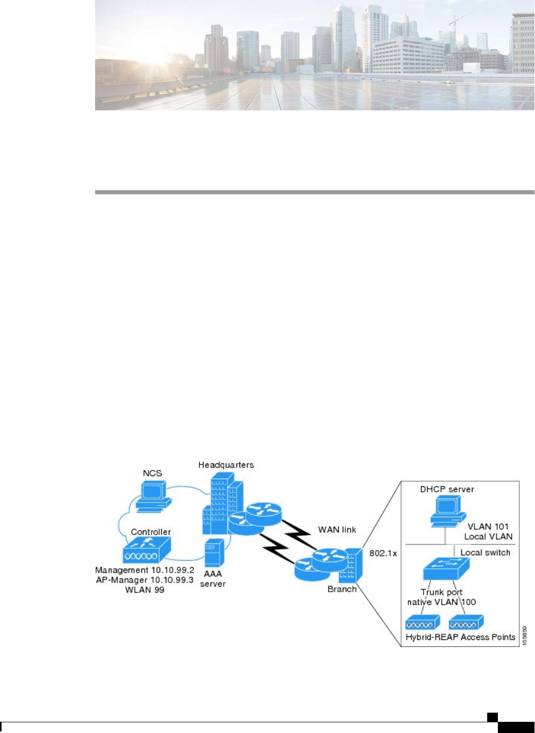
CHAPTER 137
Configuring FlexConnect
•Information About FlexConnect, page 891
•Restrictions for FlexConnect, page 896
•Configuring FlexConnect, page 897
Information About FlexConnect
FlexConnect (previously known as Hybrid Remote Edge Access Point or H-REAP) is a wireless solution for
branch office and remote office deployments. It enables customers to configure and control access points in
a branch or remote office from the corporate office through a wide area network (WAN) link without deploying
a controller in each office. The FlexConnect access points can switch client data traffic locally and perform
client authentication locally when their connection to the controller is lost. When they are connected to the
controller, they can also send traffic back to the controller. In the connected mode, the FlexConnect access
point can also perform local authentication.
This figure shows a typical FlexConnect deployment.
Figure 67: FlexConnect Deployment
Cisco Wireless LAN Controller Configuration Guide, Release 7.4
OL-28744-01 891

The controller software has a more robust fault tolerance methodology to FlexConnect access points. In
previous releases, whenever a FlexConnect access point disassociates from a controller, it moves to the
standalone mode. The clients that are centrally switched are disassociated. However, the FlexConnect access
point continues to serve locally switched clients. When the FlexConnect access point rejoins the controller
(or a standby controller), all clients are disconnected and are authenticated again. This functionality has been
enhanced and the connection between the clients and the FlexConnect access points are maintained intact and
the clients experience seamless connectivity. This feature can be used only when both the access point and
the controller have the same configuration.
Clients that are centrally authenticated are reauthenticated.
Session timeout and reauthentication is performed when the access point establishes a connected to the
controller.
After the client connection has been established, the controller does not restore the original attributes of the
client. The client username, current rate and supported rates, and listen interval values are reset to the default
values only after the session timer expires.
There is no deployment restriction on the number of FlexConnect access points per location. Multiple
FlexConnect groups can be defined in a single location.
The controller can send multicast packets in the form of unicast or multicast packets to the access point. In
FlexConnect mode, the access point can receive multicast packets only in unicast form.
FlexConnect access points support a 1-1 network address translation (NAT) configuration. They also support
port address translation (PAT) for all features except true multicast. Multicast is supported across NAT
boundaries when configured using the Unicast option. FlexConnect access points also support a many-to-one
NAT/PAT boundary, except when you want true multicast to operate for all centrally switched WLANs.
Although NAT and PAT are supported for FlexConnect access points, they are not supported on the
corresponding controller. Cisco does not support configurations in which the controller is behind a
NAT/PAT boundary.
Note
VPN and PPTP are supported for locally switched traffic if these security types are accessible locally at the
access point.
FlexConnect access points support multiple SSIDs.
Workgroup bridges and Universal Workgroup bridges are supported on FlexConnect access points for locally
switched clients.
FlexConnect supports IPv6 clients by bridging the traffic to local VLAN, similar to IPv4 operation. FlexConnect
supports Client Mobility for a group of up to 100 access points.
FlexConnect Authentication Process
When an access point boots up, it looks for a controller. If it finds one, it joins the controller, downloads the
latest software image and configuration from the controller, and initializes the radio. It saves the downloaded
configuration in nonvolatile memory for use in standalone mode.
Once the access point is rebooted after downloading the latest controller software, it must be converted
to the FlexConnect mode. This can done using the GUI or CLI.
Note
Cisco Wireless LAN Controller Configuration Guide, Release 7.4
892 OL-28744-01
Information About FlexConnect

A FlexConnect access point can learn the controller IP address in one of these ways:
•If the access point has been assigned an IP address from a DHCP server, it can discover a controller
through the regular CAPWAP or LWAPP discovery process.
OTAP is no longer supported on the controllers with 6.0.196 code and above.Note
•If the access point has been assigned a static IP address, it can discover a controller through any of the
discovery process methods except DHCP option 43. If the access point cannot discover a controller
through Layer 3 broadcast, we recommend DNS resolution. With DNS, any access point with a static
IP address that knows of a DNS server can find at least one controller.
•If you want the access point to discover a controller from a remote network where CAPWAP or LWAPP
discovery mechanisms are not available, you can use priming. This method enables you to specify
(through the access point CLI) the controller to which the access point is to connect.
For more information about how access points find controllers, see the controller
deployment guide at: http://www.cisco.com/en/US/docs/wireless/technology/controller/
deployment/guide/dep.html.
Note
When a FlexConnect access point can reach the controller (referred to as the connected mode), the controller
assists in client authentication. When a FlexConnect access point cannot access the controller, the access point
enters the standalone mode and authenticates clients by itself.
The LEDs on the access point change as the device enters different FlexConnect modes. See the hardware
installation guide for your access point for information on LED patterns.
Note
When a client associates to a FlexConnect access point, the access point sends all authentication messages to
the controller and either switches the client data packets locally (locally switched) or sends them to the
controller (centrally switched), depending on the WLAN configuration. With respect to client authentication
(open, shared, EAP, web authentication, and NAC) and data packets, the WLAN can be in any one of the
following states depending on the configuration and state of controller connectivity:
•central authentication, central switching—In this state, the controller handles client authentication, and
all client data is tunneled back to the controller. This state is valid only in connected mode.
•central authentication, local switching—In this state, the controller handles client authentication, and
the FlexConnect access point switches data packets locally. After the client authenticates successfully,
the controller sends a configuration command with a new payload to instruct the FlexConnect access
point to start switching data packets locally. This message is sent per client. This state is applicable only
in connected mode.
•local authentication, local switching—In this state, the FlexConnect access point handles client
authentication and switches client data packets locally. This state is valid in standalone mode and
connected mode.
In connected mode, the access point provides minimal information about the locally authenticated client
to the controller. The following information is not available to the controller:
Cisco Wireless LAN Controller Configuration Guide, Release 7.4
OL-28744-01 893
Information About FlexConnect

◦Policy type
◦Access VLAN
◦VLAN name
◦Supported rates
◦Encryption cipher
Local authentication is useful where you cannot maintain a remote office setup of a minimum
bandwidth of 128 kbps with the round-trip latency no greater than 100 ms and the maximum
transmission unit (MTU) no smaller than 500 bytes. In local authentication, the authentication
capabilities are present in the access point itself. Local authentication reduces the latency
requirements of the branch office.
Local authentication can only be enabled on the WLAN of a FlexConnect access point
that is in local switching mode.
Notes about local authentication are as follows:
Note
◦Guest authentication cannot be done on a FlexConnect local authentication-enabled WLAN.
◦Local RADIUS on the controller is not supported.
◦Once the client has been authenticated, roaming is only supported after the controller and the other
FlexConnect access points in the group are updated with the client information.
◦Local authentication in connected mode requires a WLAN configuration.
When locally switched clients that are connected to a FlexConnect access point renew
the IP addresses, on joining back, the client continues to stay in the run state. These
clients are not reauthenticated by the controller.
Note
•authentication down, switch down—In this state, the WLAN disassociates existing clients and stops
sending beacon and probe requests. This state is valid in both standalone mode and connected mode.
•authentication down, local switching—In this state, the WLAN rejects any new clients trying to
authenticate, but it continues sending beacon and probe responses to keep existing clients alive. This
state is valid only in standalone mode.
When a FlexConnect access point enters standalone mode, WLANs that are configured for open, shared,
WPA-PSK, or WPA2-PSK authentication enter the “local authentication, local switching”state and continue
new client authentications. In controller software release 4.2 or later releases, this configuration is also correct
for WLANs that are configured for 802.1X, WPA-802.1X, WPA2-802.1X, or CCKM, but these authentication
types require that an external RADIUS server be configured. You can also configure a local RADIUS server
on a FlexConnect access point to support 802.1X in a standalone mode or with local authentication.
Other WLANs enter either the “authentication down, switching down”state (if the WLAN was configured
for central switching) or the “authentication down, local switching”state (if the WLAN was configured for
local switching).
Cisco Wireless LAN Controller Configuration Guide, Release 7.4
894 OL-28744-01
Information About FlexConnect

When FlexConnect access points are connected to the controller (rather than in standalone mode), the controller
uses its primary RADIUS servers and accesses them in the order specified on the RADIUS Authentication
Servers page or in the config radius auth add CLI command (unless the server order is overridden for a
particular WLAN). However, to support 802.1X EAP authentication, FlexConnect access points in standalone
mode need to have their own backup RADIUS server to authenticate clients.
A controller does not use a backup RADIUS server. The controller uses the backup RADIUS server in
local authentication mode.
Note
You can configure a backup RADIUS server for individual FlexConnect access points in standalone mode
by using the controller CLI or for groups of FlexConnect access points in standalone mode by using either
the GUI or CLI. A backup server configured for an individual access point overrides the backup RADIUS
server configuration for a FlexConnect.
When a FlexConnect access point enters standalone mode, it disassociates all clients that are on centrally
switched WLANs. For web-authentication WLANs, existing clients are not disassociated, but the FlexConnect
access point stops sending beacons when the number of associated clients reaches zero (0). It also sends
disassociation messages to new clients associating to web-authentication WLANs. Controller-dependent
activities, such as network access control (NAC) and web authentication (guest access), are disabled, and the
access point does not send any intrusion detection system (IDS) reports to the controller. Most radio resource
management (RRM) features (such as neighbor discovery; noise, interference, load, and coverage measurements;
use of the neighbor list; and rogue containment and detection) are disabled. However, a FlexConnect access
point supports dynamic frequency selection in standalone mode.
When web-authentication is used on FlexConnect access points at a remote site, the clients get the IP address
from the remote local subnet. To resolve the initial URL request, the DNS is accessible through the subnet's
default gateway. In order for the controller to intercept and redirect the DNS query return packets, these
packets must reach the controller at the data center through a CAPWAP connection. During the
web-authentication process, the FlexConnect access points allows only DNS and DHCP messages; the access
points forward the DNS reply messages to the controller before web-authentication for the client is complete.
After web-authentication for the client is complete, all the traffic is switched locally.
If your controller is configured for NAC, clients can associate only when the access point is in connected
mode. When NAC is enabled, you need to create an unhealthy (or quarantined) VLAN so that the data
traffic of any client that is assigned to this VLAN passes through the controller, even if the WLAN is
configured for local switching. After a client is assigned to a quarantined VLAN, all of its data packets
are centrally switched. See the Configuring Dynamic Interfaces section for information about creating
quarantined VLANs and the Configuring NAC Out-of-Band section for information about configuring
NAC out-of-band support.
Note
When a FlexConnect access point enters into a standalone mode, the following occurs:
•The access point checks whether it is able to reach the default gateway via ARP. If so, it will continue
to try and reach the controller.
If the access point fails to establish the ARP, the following occurs:
•The access point attempts to discover for five times and if it still cannot find the controller, it tries to
renew the DHCP on the ethernet interface to get a new DHCP IP.
Cisco Wireless LAN Controller Configuration Guide, Release 7.4
OL-28744-01 895
Information About FlexConnect

•The access point will retry for five times, and if that fails, the access point will renew the IP address of
the interface again, this will happen for three attempts.
•If the three attempts fail, the access point will fall back to the static IP and will reboot (only if the access
point is configured with a static IP).
•Reboot is done to remove the possibility of any unknown error the access point configuration.
Once the access point reestablishes a connection with the controller, it disassociates all clients, applies new
configuration information from the controller, and allows client connectivity again.
Restrictions for FlexConnect
•When you apply a configuration change to a locally switched WLAN, the access point resets the radio,
causing associated client devices to disassociate (including the clients that are not associated to the
modified WLAN). However, this behavior does not occur if the modified WLAN is centrally switched.
We recommend that you perform a configuration change only during a maintenance window.
•You can deploy a FlexConnect access point with either a static IP address or a DHCP address. In the
case of DHCP, a DHCP server must be available locally and must be able to provide the IP address for
the access point at bootup.
•FlexConnect supports up to four fragmented packets or a minimum 500-byte maximum transmission
unit (MTU) WAN link.
•FlexConnect is supported only on the following access points: 1040, 1130, 1140, 1250, 1240, 1260,
1600, 1550, 2600, 3500, 3600, OEAP 600, ISR 891, and ISR 881.
•Round-trip latency must not exceed 300 milliseconds (ms) between the access point and the controller,
and CAPWAP control packets must be prioritized over all other traffic. In cases where you cannot
achieve the 300 milliseconds round-trip latency, you can configure the access point to perform local
authentication.
•Client connections are restored only for locally switched clients that are in the RUN state when the
access point moves from standalone mode to connected mode. After the access point moves from the
standalone mode to the connected mode, the access point’s radio is also reset.
•The configuration on the controller must be the same between the time the access point went into
standalone mode and the time the access point came back to connected mode. Similarly, if the access
point is falling back to a secondary or backup controller, the configuration between the primary and
secondary or backup controller must be the same.
•A newly connected access point cannot be booted in FlexConnect mode.
•To use CCKM fast roaming with FlexConnect access points, you must configure FlexConnect Groups.
•NAC out-of-band integration is supported only on WLANs configured for FlexConnect central switching.
It is not supported for use on WLANs configured for FlexConnect local switching.
•The primary and secondary controllers for a FlexConnect access point must have the same configuration.
Otherwise, the access point might lose its configuration, and certain features (such as WLAN overrides,
VLANs, static channel number, and so on) might not operate correctly. In addition, make sure to duplicate
the SSID of the FlexConnect access point and its index number on both controllers.
Cisco Wireless LAN Controller Configuration Guide, Release 7.4
896 OL-28744-01
Restrictions for FlexConnect

•The QoS profile per-user bandwidth contracts are not supported for FlexConnect locally switched
WLANs. The QoS per-user bandwidth contracts are only supported for centrally switched WLANs and
APs in the local mode.
•Do not connect access points in FlexConnect mode directly to a 2500 Series Controller.
•If you configure a FlexConnect access point with a syslog server configured on the access point, after
the access point is reloaded and the native VLAN other than 1, at time of initialization, few syslog
packets from the access point are tagged with VLAN ID 1. This is a known issue.
•MAC Filtering is not supported on FlexConnect access points in standalone mode. However, MAC
Filtering is supported on FlexConnect access points in connected mode with local switching and central
authentication. Also, Open SSID, MAC Filtering, and RADIUS NAC for a locally switched WLAN
with FlexConnect access points is a valid configuration where MAC is checked by ISE.
•FlexConnect does not support IPv6 ACLs, neighbor discovery caching, and DHCPv6 snooping of IPv6
NDP packets.
•FlexConnect does not display any IPv6 client addresses within the client detail page.
•FlexConnect Access Points with Locally Switched WLAN cannot perform IP Source Guard and prevent
ARP spoofing. For Centrally Switched WLAN, the wireless controller performs the IP Source Guard
and ARP Spoofing.
•To prevent ARP spoofing attacks in FlexConnect AP with Local Switching, we recommend that you
use ARP Inspection.
•When you enable local switching on WLAN for the Flexconnect APs, then APs perform local switching.
However, for the APs in local mode, central switching is performed.
•For Wi-Fi Protected Access version 2 (WPA2) in FlexConnect standalone mode or local-auth in connected
mode or CCKM fast-roaming in connected mode, only Advanced Encryption Standard (AES) is supported.
•For Wi-Fi Protected Access (WPA) in FlexConnect standalone mode or local-auth in connected mode
or CCKM fast-roaming in connected mode, only Temporal Key Integrity Protocol (TKIP) is supported.
•WPA2 with TKIP and WPA with AES is not supported in standalone mode, local-auth in connected
mode, and CCKM fast-roaming in connected mode.
•AVC is not supported on APs in FlexConnect local switched mode.
Configuring FlexConnect
The configuration tasks must be performed in the order in which they are listed.Note
Configuring the Switch at a Remote Site
Step 1 Attach the access point that will be enabled for FlexConnect to a trunk or access port on the switch.
The sample configuration in this procedure shows the FlexConnect access point connected to a trunk port on
the switch.
Note
Cisco Wireless LAN Controller Configuration Guide, Release 7.4
OL-28744-01 897
Configuring FlexConnect

Step 2 See the sample configuration in this procedure to configure the switch to support the FlexConnect access point.
In this sample configuration, the FlexConnect access point is connected to trunk interface FastEthernet 1/0/2 with native
VLAN 100. The access point needs IP connectivity on the native VLAN. The remote site has local servers/resources on
VLAN 101. A DHCP pool is created in the local switch for both VLANs in the switch. The first DHCP pool (NATIVE)
is used by the FlexConnect access point, and the second DHCP pool (LOCAL-SWITCH) is used by the clients when
they associate to a WLAN that is locally switched. The bolded text in the sample configuration shows these settings.
A sample local switch configuration is as follows:
ip dhcp pool NATIVE
network 209.165.200.224 255.255.255.224
default-router 209.165.200.225
dns-server 192.168.100.167
!
ip dhcp pool LOCAL-SWITCH
network 209.165.201.224 255.255.255.224
default-router 209.165.201.225
dns-server 192.168.100.167
!
interface FastEthernet1/0/1
description Uplink port
no switchport
ip address 209.165.202.225 255.255.255.224
!
interface FastEthernet1/0/2
description the Access Point port
switchport trunk encapsulation dot1q
switchport trunk native vlan 100
switchport trunk allowed vlan 101
switchport mode trunk
!
interface Vlan100
ip address 209.165.200.225 255.255.255.224
!
interface Vlan101
ip address 209.165.201.225 255.255.255.224
end
!
Configuring the Controller for FlexConnect
You can configure the controller for FlexConnect in two environments:
•Centrally switched WLAN
•Locally switched WLAN
The controller configuration for FlexConnect consists of creating centrally switched and locally switched
WLANs. This table shows three WLAN scenarios.
Cisco Wireless LAN Controller Configuration Guide, Release 7.4
898 OL-28744-01
Configuring FlexConnect

Table 26: WLANs Example
Interface Mapping (VLAN)SwitchingAuthenticationSecurityWLAN
management (centrally
switched VLAN)
CentralCentralWPA1+WPA2employee
101 (locally switched
VLAN)
LocalLocalWPA1+WPA2
(PSK)
employee-local
management (centrally
switched VLAN)
CentralCentralWeb authenticationguest-central
101 (locally switched
VLAN)
LocalLocalWPA1+WPA2employee
-local-auth
Configuring the Controller for FlexConnect for a Centrally Switched WLAN Used for Guest Access
Before You Begin
You must have created guest user accounts. For more information about creating guest user accounts, see the
Cisco Wireless LAN Controller System Management Guide.
Step 1 Choose WLANs to open the WLANs page.
Step 2 From the drop-down list, choose Create New and click Go to open the WLANs > New page .
Step 3 From the Type drop-down list, choose WLAN.
Step 4 In the Profile Name text box, enter guest-central.
Step 5 In the WLAN SSID text box, enter guest-central.
Step 6 From the WLAN ID drop-down list, choose an ID for the WLAN.
Step 7 Click Apply. The WLANs > Edit page appears.
Step 8 In the General tab, select the Status check box to enable the WLAN.
Step 9 In the Security > Layer 2 tab, choose None from the Layer 2 Security drop-down list.
Step 10 In the Security > Layer 3 tab:
a) Choose None from the Layer 3 Security drop-down list.
b) Choose the Web Policy check box.
c) Choose Authentication.
Note
If you are using an external web server, you must configure a preauthentication access control list (ACL) on the
WLAN for the server and then choose this ACL as the WLAN preauthentication ACL on the Layer 3 tab.
Step 11 Click Apply.
Step 12 Click Save Configuration.
Cisco Wireless LAN Controller Configuration Guide, Release 7.4
OL-28744-01 899
Configuring FlexConnect

Configuring the Controller for FlexConnect (GUI)
Step 1 Choose WLANs to open the WLANs page.
Step 2 From the drop-down list, choose Create New and click Go to open the WLANs > New page.
Step 3 From the Type drop-down list, choose WLAN.
Step 4 In the Profile Name text box, enter a unique profile name for the WLAN.
Step 5 In the WLAN SSID text box, enter a name for the WLAN.
Step 6 From the WLAN ID drop-down list, choose the ID number for this WLAN.
Step 7 Click Apply to commit your changes. The WLANs > Edit page appears.
Step 8 You can configure the controller for FlexConnect in both centrally switched and locally switched WLANs:
To configure the controller for FlexConnect in a centrally switched WLAN:
a) In the General tab, select the Status check box to enable the WLAN.
b) If you have enabled NAC and have created a quarantined VLAN and want to use it for this WLAN, select the interface
from the Interface/Interface Group(G) drop-down list in the General tab.
c) In the Security > Layer 2 tab, choose WPA+WPA2 from the Layer 2 Security drop-down list and then set the
WPA+WPA2 parameters as required.
To configure the controller for FlexConnect in a locally switched WLAN:
a) In the General tab, select the Status check box to enable the WLAN.
b) If you have enabled NAC and have created a quarantined VLAN and want to use it for this WLAN, select the interface
from the Interface/Interface Group(G) drop-down list in the General tab.
c) In the Security > Layer 2 tab, select WPA+WPA2 from the Layer 2 Security drop-down list and then set the
WPA+WPA2 parameters as required.
d) In the Advanced tab:
•Select or unselect the FlexConnect Local Switching check box to enable or disable local switching of client
data associated with the APs in FlexConnect mode.
The guidelines and limitations for this feature are as follows:Note
•When you enable local switching, any FlexConnect access point that advertises this WLAN is
able to locally switch data packets (instead of tunneling them to the controller).
•When you enable FlexConnect local switching, the controller is enabled to learn the client’s IP
address by default. However, if the client is configured with Fortress Layer 2 encryption, the
controller cannot learn the client’s IP address, and the controller periodically drops the client.
Disable the client IP address learning feature so that the controller maintains the client connection
without waiting to learn the client’s IP address. The ability to disable this option is supported
only with FlexConnect local switching; it is not supported with FlexConnect central switching.
•For FlexConnect access points, the interface mapping at the controller for WLANs that is
configured for FlexConnect Local Switching is inherited at the access point as the default VLAN
tagging. This mapping can be changed per SSID and per FlexConnect access point.
Non-FlexConnect access points tunnel all traffic back to the controller, and VLAN tagging is
determined by each WLAN’s interface mapping.
•Select or unselect the FlexConnect Local Auth check box to enable or disable local authentication for the
WLAN.
Cisco Wireless LAN Controller Configuration Guide, Release 7.4
900 OL-28744-01
Configuring FlexConnect

•Select or unselect the Learn Client IP Address check box to enable or disable the IP address of the client to
be learned.
•Select or unselect the VLAN based Central Switching check box to enable or disable central switching on a
locally switched WLAN based on AAA overridden VLAN.
These are the guidelines and limitations for this feature:Note
•Multicast on overridden interfaces is not supported.
•This feature is available only on a per-WLAN basis, where the WLAN is locally switched.
•IPv6 ACLs, CAC, NAC, and IPv6 are not supported.
•IPv4 ACLs are supported only with VLAN-based central switching enabled and applicable only
to central switching clients on the WLAN.
•This feature is applicable to APs in FlexConnect mode in locally switched WLANs.
•This feature is not applicable to APs in Local mode.
•This feature is not supported on APs in FlexConnect mode in centrally switched WLANs.
•This feature is supported on central authentication only.
•This features is not supported on web authentication security clients.
•Layer 3 roaming for local switching clients is not supported.
•Select or unselect the Central DHCP Processing check box to enable or disable the feature. When you enable
this feature, the DHCP packets received from AP are centrally switched to the controller and then forwarded
to the corresponding VLAN based on the AP and the SSID.
•Select or unselect the Override DNS check box to enable or disable the overriding of the DNS server address
on the interface assigned to the locally switched WLAN. When you override DNS in centrally switched WLANs,
the clients get their DNS server IP address from the AP, not from the controller.
•Select or unselect the NAT-PAT check box to enable or disable Network Address Translation (NAT) and Port
Address Translation (PAT) on locally switched WLANs. You must enable Central DHCP Processing to enable
NAT and PAT.
Step 9 Click Apply.
Step 10 Click Save Configuration.
Configuring the Controller for FlexConnect (CLI)
•config wlan flexconnect local-switching wlan_id enable—Configures the WLAN for local switching.
Cisco Wireless LAN Controller Configuration Guide, Release 7.4
OL-28744-01 901
Configuring FlexConnect

When you enable FlexConnect local switching, the controller waits to learn the client
IP address by default. However, if the client is configured with Fortress Layer 2
encryption, the controller cannot learn the client IP address, and the controller periodically
drops the client. Use the config wlan flexconnect learn-ipaddr wlan_id disable
command to disable the client IP address learning feature so that the controller maintains
the client connection without waiting to learn the client’s IP address. The ability to
disable this feature is supported only with FlexConnect local switching; it is not supported
with FlexConnect central switching. To enable this feature, enter the config wlan
flexconnect learn-ipaddr wlan_id enable command.
Note
When a WLAN is locally switched (LS), you must use the config wlan flexconnect
learn-ipaddr wlan-id {enable |disable} command. When the WLAN is centrally
switched (CS), you must use the config wlan learn-ipaddr-cswlan wlan-id {enable |
disable} command.
Note
•config wlan flexconnect local-switching wlan_id {enable |disable}—Configures the WLAN for central
switching.
•config wlan flexconnect vlan-central-switching wlan_id {enable |disable}—Configures central
switching on a locally switched WLAN based on an AAA overridden VLAN.
The guidelines and limitations for this feature are as follows:
•Multicast on overridden interfaces is not supported.
•This feature is available only on a per-WLAN basis, where the WLAN is locally switched.
•IPv6 ACLs, CAC, NAC, and IPv6 are not supported.
•IPv4 ACLs are supported only with VLAN-based central switching enabled and applicable only
to central switching clients on the WLAN.
•This feature is applicable to APs in FlexConnect mode in locally switched WLANs.
•This feature is not applicable to APs in Local mode.
•This feature is not supported on APs in FlexConnect mode in centrally switched WLANs.
•This feature is supported on central authentication only.
•This features is not supported on web authentication security clients.
•Layer 3 roaming for local switching clients is not supported.
Use these commands to get FlexConnect information:
•show ap config general Cisco_AP—Shows VLAN configurations.
•show wlan wlan_id—Shows whether the WLAN is locally or centrally switched.
•show client detail client_mac—Shows whether the client is locally or centrally switched.
Use these commands to obtain debug information:
Cisco Wireless LAN Controller Configuration Guide, Release 7.4
902 OL-28744-01
Configuring FlexConnect

•debug flexconnect aaa {event |error} {enable |disable}—Enables or disables debugging of
FlexConnect backup RADIUS server events or errors.
•debug flexconnect cckm {enable |disable}—Enables or disables debugging of FlexConnect CCKM.
•debug flexconnect {enable |disable}—Enables or disables debugging of FlexConnect Groups.
•debug pem state {enable |disable}—Enables or disables debugging of the policy manager state machine.
•debug pem events {enable |disable}—Enables or disables debugging of policy manager events.
Configuring an Access Point for FlexConnect
Configuring an Access Point for FlexConnect (GUI)
Ensure that the access point has been physically added to your network.
Step 1 Choose Wireless to open the All APs page.
Step 2 Click the name of the desired access point. The All APs > >Details page appears.
Step 3 From the AP Mode drop-down list, choose FlexConnect to enable FlexConnect for this access point.
The last parameter in the Inventory tab indicates whether the access point can be configured for FlexConnect.Note
Step 4 Click Apply to commit your changes and to cause the access point to reboot.
Step 5 Choose the FlexConnect tab to open the All APs > Details for (FlexConnect) page.
If the access point belongs to a FlexConnect group, the name of the group appears in the FlexConnect Name text box.
Step 6 Select the VLAN Support check box and enter the number of the native VLAN on the remote network (such as 100)
in the Native VLAN ID text box.
By default, a VLAN is not enabled on the FlexConnect access point. After FlexConnect is enabled, the access
point inherits the VLAN ID associated to the WLAN. This configuration is saved in the access point and received
after the successful join response. By default, the native VLAN is 1. One native VLAN must be configured per
FlexConnect access point in a VLAN-enabled domain. Otherwise, the access point cannot send and receive
packets to and from the controller.
Note
To preserve the VLAN mappings in the access point after an upgrade or downgrade, it is necessary that the
access point join is restricted to the controller for which it is primed. That is, no other discoverable controller
with a different configuration should be available by other means. Similarly, at the time the access point joins,
if it moves across controllers that have different VLAN mappings, the VLAN mappings at the access point may
get mismatched.
Note
Step 7 Click Apply. The access point temporarily loses its connection to the controller while its Ethernet port is reset.
Step 8 Click the name of the same access point and then click the FlexConnect tab.
Step 9 Click VLAN Mappings to open the All APs >Access Point Name > VLAN Mappings page.
Step 10 Enter the number of the VLAN from which the clients will get an IP address when doing local switching (VLAN 101,
in this example) in the VLAN ID text box.
Step 11 To configure Web Authentication ACLs, do the following:
a) Click the External WebAuthentication ACLs link to open the ACL mappings page. The ACL Mappings page lists
details of WLAN ACL mappings and web policy ACLs.
b) In the WLAN Id box, enter the WLAN ID.
c) From the WebAuth ACL drop-down list, choose the FlexConnect ACL.
Cisco Wireless LAN Controller Configuration Guide, Release 7.4
OL-28744-01 903
Configuring FlexConnect

To create a FlexConnect ACL, choose Wireless > FlexConnect Groups > FlexConnect ACLs, click New,
enter the FlexConnect ACL name, and click Apply.
Note
d) Click Add.
e) Click Apply.
Step 12 To configure Local Split ACLs:
a) Click the Local Split ACLs link to open the ACL Mappings page.
b) In the WLAN Id box, enter the WLAN ID.
c) From the Local-Split ACL drop-down list, choose the FlexConnect ACL.
To create a FlexConnect ACL, choose Wireless > FlexConnect Groups > FlexConnect ACLs, click New,
enter the FlexConnect ACL name, and click Apply.
Note
If a client that connects over a WAN link associated with a centrally switched WLAN has to send some traffic to a
device present in the local site, the client has to send traffic over CAPWAP to the controller and then get the same
traffic back to the local site either over CAPWAP or using some offband connectivity. This process unnecessarily
consumes WAN link bandwidth. To avoid this issue, you can use the split tunneling feature, which allows the traffic
sent by a client to be classified based on the packet contents. The matching packets are locally switched and the rest
of the traffic is centrally switched. The traffic that is sent by the client that matches the IP address of the device
present in the local site can be classified as locally switched traffic and the rest of the traffic as centrally switched.
To configure local split tunneling on an AP, ensure that you have enabled DCHP Required on the WLAN, which
ensures that the client associating with the split WLAN does DHCP.
Local split tunneling is not supported on Cisco 1500 Series, Cisco 1130, and Cisco 1240 access points, and
does not work for clients with static IP address.
Note
d) Click Add.
Step 13 To configure Central DHCP processing:
a) In the WLAN Id box, enter the WLAN ID with which you want to map Central DHCP.
b) Select or unselect the Central DHCP check box to enable or disable Central DHCP for the mapping.
c) Select or unselect the Override DNS check box to enable or disable overriding of DNS for the mapping.
d) Select or unselect the NAT-PAT check box to enable or disable network address translation and port address translation
for the mapping.
e) Click Add to add the Central DHCP - WLAN mapping.
Step 14 To map a locally switched WLAN with a WebAuth ACL, follow these steps:
a) In the WLAN Id box, enter the WLAN ID.
b) From the WebAuth ACL drop-down list, choose the FlexConnect ACL.
To create a FlexConnect ACL, choose Wireless > FlexConnect Groups > FlexConnect ACLs, click New,
enter the FlexConnect ACL name, and click Apply.
Note
c) Click Add.
The FlexConnect ACLs that are specific to an AP have the highest priority. The FlexConnect ACLs that are
specific to WLANs have the lowest priority.
Note
Step 15 From the WebPolicy ACL drop-down list, choose a FlexConnect ACL and then click Add to configure the FlexConnect
ACL as a web policy.
You can configure up to 16 Web Policy ACLs that are specific to an access
point.
Note
Step 16 Click Apply.
Step 17 Click Save Configuration.
Repeat this procedure for any additional access points that need to be configured for FlexConnect at the remote
site.
Note
Cisco Wireless LAN Controller Configuration Guide, Release 7.4
904 OL-28744-01
Configuring FlexConnect

Configuring an Access Point for FlexConnect (CLI)
•config ap mode flexconnect Cisco_AP—Enables FlexConnect for this access point.
•config ap flexconnect radius auth set {primary | secondary}ip_address auth_port secret
Cisco_AP—Configures a primary or secondary RADIUS server for a specific FlexConnect access point.
Only the Session Timeout RADIUS attribute is supported in standalone mode. All other
attributes as well as RADIUS accounting are not supported.
Note
To delete a RADIUS server that is configured for a FlexConnect access point, enter the
config ap flexconnect radius auth delete {primary | secondary}Cisco_AP command.
Note
•config ap flexconnect vlan wlan wlan_id vlan-id Cisco_AP—Enables you to assign a VLAN ID to this
FlexConnect access point. By default, the access point inherits the VLAN ID associated to the WLAN.
•config ap flexconnect vlan {enable | disable}Cisco_AP—Enables or disables VLAN tagging for this
FlexConnect access point. By default, VLAN tagging is not enabled. After VLAN tagging is enabled
on the FlexConnect access point, WLANs that are enabled for local switching inherit the VLAN assigned
at the controller.
•config ap flexconnect vlan native vlan-id Cisco_AP—Enables you to configure a native VLAN for
this FlexConnect access point. By default, no VLAN is set as the native VLAN. One native VLAN must
be configured per FlexConnect access point (when VLAN tagging is enabled). Make sure the switch
port to which the access point is connected has a corresponding native VLAN configured as well. If the
FlexConnect access point’s native VLAN setting and the upstream switch port native VLAN do not
match, the access point cannot transmit packets to and from the controller.
To save the VLAN mappings in the access point after an upgrade or downgrade, you
should restrict the access point to join the controller for which it is primed. No other
discoverable controller with a different configuration should be available by other means.
Similarly, at the time the access point joins, if it moves across controllers that have
different VLAN mappings, the VLAN mappings at the access point might get
mismatched.
Note
•Configure the mapping of a Web-Auth or a Web Passthrough ACL to a WLAN for an access point in
FlexConnect mode by entering this command:
config ap flexconnect web-auth wlan wlan_id cisco_ap acl_name {enable |disable}
Cisco Wireless LAN Controller Configuration Guide, Release 7.4
OL-28744-01 905
Configuring FlexConnect

The FlexConnect ACLs that are specific to an AP have the highest priority. The
FlexConnect ACLs that are specific to WLANs have the lowest priority.
Note
•Configure a Policy ACL on an AP in FlexConnect mode by entering this command:
config ap flexconnect acl {add |delete}acl_name cisco_ap
You can configure up to 16 Policy ACLs that are specific to an access point.Note
•To configure local split tunneling on a per-AP basis, enter this command:
config ap local-split {enable |disable}wlan-id acl acl-name ap-name
•Configure central DHCP on the AP per WLAN by entering this command:
config ap flexconnect central-dhcp wlan-id ap-name {enable override dns |disable |delete}
The gratuitous ARP for the gateway is sent by the access point to the client, which
obtained an IP address from the central site. This is performed to proxy the gateway by
the access point.
Note
Use these commands on the FlexConnect access point to get status information:
•show capwap reap status—Shows the status of the FlexConnect access point (connected or standalone).
•show capwap reap association—Shows the list of clients associated to this access point and their SSIDs.
Use these commands on the FlexConnect access point to get debug information:
•debug capwap reap—Shows general FlexConnect activities.
•debug capwap reap mgmt—Shows client authentication and association messages.
•debug capwap reap load—Shows payload activities, which are useful when the FlexConnect access
point boots up in standalone mode.
•debug dot11 mgmt interface—Shows 802.11 management interface events.
•debug dot11 mgmt msg—Shows 802.11 management messages.
•debug dot11 mgmt ssid—Shows SSID management events.
•debug dot11 mgmt state-machine—Shows the 802.11 state machine.
•debug dot11 mgmt station—Shows client events.
Cisco Wireless LAN Controller Configuration Guide, Release 7.4
906 OL-28744-01
Configuring FlexConnect

Configuring an Access Point for Local Authentication on a WLAN (GUI)
Step 1 Choose WLANs to open the WLANs page.
Step 2 Click the ID of the WLAN. The WLANs > Edit page appears.
Step 3 Clicked the Advanced tab to open the WLANs >Edit (WLAN Name) page.
Step 4 Select the FlexConnect Local Switching check box to enable FlexConnect local switching.
Step 5 Select the FlexConnect Local Auth check box to enable FlexConnect local authentication.
Do not connect access points in FlexConnect mode directly to 2500 Series Controllers.Caution
Step 6 Click Apply to commit your changes.
Configuring an Access Point for Local Authentication on a WLAN (CLI)
Before You Begin
Before you begin, you must have enabled local switching on the WLAN where you want to enable local
authentication for an access point. For instructions on how to enable local switching on the WLAN, see the
Configuring the Controller for FlexConnect (CLI) section.
•config wlan flexconnect ap-auth wlan_id {enable |disable}—Configures the access point to enable
or disable local authentication on a WLAN.
Do not connect the access points in FlexConnect mode directly to Cisco 2500 Series Controllers.Caution
•show wlan wlan-id —Displays the configuration for the WLAN. If local authentication is enabled, the
following information appears:
...
...
Web Based Authentication...................... Disabled
Web-Passthrough............................... Disabled
Conditional Web Redirect...................... Disabled
Splash-Page Web Redirect...................... Disabled
Auto Anchor................................... Disabled
FlexConnect Local Switching........................ Enabled
FlexConnect Local Authentication................... Enabled
FlexConnect Learn IP Address....................... Enabled
Client MFP.................................... Optional
Tkip MIC Countermeasure Hold-down Timer....... 60
Call Snooping.................................... Disabled
Roamed Call Re-Anchor Policy..................... Disabled
...
...
Connecting Client Devices to WLANs
Follow the instructions for your client device to create profiles to connect to the WLANs you created in the
Configuring the Controller for FlexConnect.
Cisco Wireless LAN Controller Configuration Guide, Release 7.4
OL-28744-01 907
Configuring FlexConnect

In the example scenarios (see Table 26: WLANs Example), there are three profiles on the client:
1To connect to the “employee”WLAN, create a client profile that uses WPA/WPA2 with PEAP-MSCHAPV2
authentication. After the client becomes authenticated, the client gets an IP address from the management
VLAN of the controller.
2To connect to the “local-employee”WLAN, create a client profile that uses WPA/WPA2 authentication.
After the client becomes authenticated, the client gets an IP address from VLAN 101 on the local switch.
3To connect to the “guest-central”WLAN, create a client profile that uses open authentication. After the
client becomes authenticated, the client gets an IP address from VLAN 101 on the network local to the
access point. After the client connects, the local user can type any HTTP address in the web browser. The
user is automatically directed to the controller to complete the web-authentication process. When the web
login page appears, the user enters the username and password.
To determine if a client’s data traffic is being locally or centrally switched, choose Monitor > Clients on the
controller GUI, click the Detail link for the desired client, and look at the Data Switching parameter under
AP Properties.
Cisco Wireless LAN Controller Configuration Guide, Release 7.4
908 OL-28744-01
Configuring FlexConnect

CHAPTER 138
Configuring FlexConnect ACLs
•Information About Access Control Lists, page 909
•Restrictions for FlexConnect ACLs, page 909
•Configuring FlexConnect ACLs (GUI), page 910
•Configuring FlexConnect ACLs (CLI), page 912
•Viewing and Debugging FlexConnect ACLs (CLI), page 913
Information About Access Control Lists
An access control list (ACL) is a set of rules used to limit access to a particular interface (for example, if you
want to restrict a wireless client from pinging the management interface of the controller). ACLs enable access
control of network traffic. After ACLs are configured on the controller, you can apply them to the management
interface, the AP-Manager interface, any of the dynamic interfaces, or a WLAN. ACLs enable you to control
data traffic to and from wireless clients or to the controller CPU.You can configure ACLs on FlexConnect
access points to enable effective usage and access control of locally switched data traffic on an access point.
The FlexConnect ACLs can be applied to VLAN interfaces on access points in both the Ingress and Egress
mode.
Existing interfaces on an access point can be mapped to ACLs. The interfaces can be created by configuring
a WLAN-VLAN mapping on a FlexConnect access point.
The FlexConnect ACLs can be applied to an access point’s VLAN only if VLAN support is enabled on the
FlexConnect access point.
Restrictions for FlexConnect ACLs
•FlexConnect ACLs can be applied only to FlexConnect access points. The configurations applied are
per AP and per VLAN.
•You can configure up to 512 ACLs on a controller.
•Non-FlexConnect ACLs that are configured on the controller cannot be applied to a FlexConnect AP.
Cisco Wireless LAN Controller Configuration Guide, Release 7.4
OL-28744-01 909

•FlexConnect ACLs do not support direction per rule. Unlike normal ACLs, Flexconnect ACLs cannot
be configured with a direction. An ACL as a whole needs to be applied to an interface as ingress or
egress.
•You can define up to 512 FlexConnect ACLs, each with up to 64 rules (or filters). Each rule has
parameters that affect its action. When a packet matches all the parameters pertaining to a rule, the action
set pertaining to that rule is applied to the packet.
•ACLs in your network might have to be modified because Control and Provisioning of Wireless Access
Points (CAPWAP) use ports that are different from the ones used by the Lightweight Access Point
Protocol (LWAPP).
•All ACLs have an implicit deny all rule as the last rule. If a packet does not match any of the rules, it is
dropped by the corresponding access point.
•ACLs mapping on the VLANs that are created on an AP using WLAN-VLAN mapping, should be
performed on a per-AP basis only. VLANs can be created on a FlexConnect group for AAA override.
These VLANs will not have any mapping for a WLAN.
•ACLs for VLANs that are created on a FlexConnect group should be mapped only on the FlexCconnect
group. If the same VLAN is present on the corresponding AP as well as the FlexConnect group, AP
VLAN will take priority. This means that if no ACL is mapped on the AP, the VLAN will not have any
ACL, even if the ACL is mapped to the VLAN on the FlexConnect group.
Configuring FlexConnect ACLs (GUI)
Step 1 Choose Security >Access Control Lists >FlexConnect Access Control Lists.
The FlexConnect ACL page is displayed.
This page lists all the FlexConnect ACLs configured on the controller. This page also shows the FlexConnect ACLs
created on the corresponding controller. To remove an ACL, hover your mouse over the blue drop-down arrow adjacent
to the corresponding ACL name and choose Remove.
Step 2 Add a new ACL by clicking New.
The Access Control Lists >New page is displayed.
Step 3 In the Access Control List Name text box, enter a name for the new ACL. You can enter up to 32 alphanumeric characters.
Step 4 Click Apply.
Step 5 When the Access Control Lists page reappears, click the name of the new ACL.
When the Access Control Lists > Edit page appears, click Add New Rule.
The Access Control Lists >Rules >New page is displayed.
Step 6 Configure a rule for this ACL as follows:
a) The controller supports up to 64 rules for each ACL. These rules are listed in order from 1 to 64. In the Sequence
text box, enter a value (between 1 and 64) to determine the order of this rule in relation to any other rules defined for
this ACL.
If rules 1 through 4 are already defined and you add rule 29, it is added as rule 5. If you add or change a
sequence number of a rule, the sequence numbers of the other rules are automatically adjusted to maintain
a continuous sequence. For instance, if you change a rule’s sequence number from 7 to 5, the rules with
sequence numbers 5 and 6 are automatically reassigned as 6 and 7, respectively.
Note
Cisco Wireless LAN Controller Configuration Guide, Release 7.4
910 OL-28744-01
Configuring FlexConnect ACLs (GUI)

b) From the Source drop-down list, choose one of these options to specify the source of the packets to which this ACL
is applicable:
•Any—Any source (This is the default value.)
•IP Address—A specific source. If you choose this option, enter the IP address and netmask of the source in
the corresponding text boxes.
c) From the Destination drop-down list, choose one of these options to specify the destination of the packets to which
this ACL applies:
•Any—Any destination (This is the default value.)
•IP Address—A specific destination. If you choose this option, enter the IP address and netmask of the destination
in the text boxes.
d) From the Protocol drop-down list, choose the protocol ID of the IP packets to be used for this ACL. The protocol
options that you can use are the following:
•Any—Any protocol (This is the default value.)
•TCP
•UDP
•ICMP—Internet Control Message Protocol
•ESP—IP Encapsulating Security Payload
•AH—Authentication Header
•GRE—Generic Routing Encapsulation
•IP in IP—Permits or denies IP-in-IP packets
•Eth Over IP—Ethernet-over-Internet Protocol
•OSPF—Open Shortest Path First
•Other—Any other Internet-Assigned Numbers Authority (IANA) protocol
If you choose Other, enter the number of the desired protocol in the Protocol text box. You can find
the list of available protocols in the INAI website.
Note
The controller can permit or deny only the IP packets in an ACL. Other types of packets (such as Address Resolution
Protocol (ARP) packets) cannot be specified.
If you chose TCP or UDP, two additional parameters, Source Port and Destination Port, are displayed. These parameters
enable you to choose a specific source port and destination port or port range. The port options are used by applications
that send and receive data to and from the networking stack. Some ports are designated for certain applications, such
as Telnet, SSH, HTTP, and so on.
e) From the DSCP drop-down list, choose one of these options to specify the differentiated services code point (DSCP)
value of this ACL. DSCP is an IP header text box that can be used to define the quality of service across the Internet.
•Any—Any DSCP (This is the default value.)
•Specific—A specific DSCP from 0 to 63, which you enter in the DSCP text box
Cisco Wireless LAN Controller Configuration Guide, Release 7.4
OL-28744-01 911
Configuring FlexConnect ACLs (GUI)

f) From the Action drop-down list, choose Deny to cause this ACL to block packets, or Permit to cause this ACL to
allow packets. The default value is Deny.
g) Click Apply.
The Access Control Lists > Edit page is displayed on which the rules for this ACL are shown.
h) Repeat this procedure to add additional rules, if any, for this ACL.
Step 7 Click Save Configuration.
Configuring FlexConnect ACLs (CLI)
•config flexconnect acl create name—Creates an ACL on a FlexConnect access point. The name must
be an IPv4 ACL name of up to 32 characters.
•config flexconnect acl delete name—Deletes a FlexConnect ACL.
•config flexconnect acl rule action acl-name rule-index {permit |deny}—Permits or denies an ACL.
•config flexconnect acl rule add acl-name rule-index—Adds an ACL rule.
•config flexconnect acl rule change index acl-name old-index new-index—Changes the index value for
an ACL rule.
•config flexconnect acl rule delete name—Deletes an ACL rule.
•config flexconnect acl rule dscp acl-name rule-index {0-63 | any }—Specifies the differentiated services
code point (DSCP) value of the rule index. DSCP is an IP header that can be used to define the quality
of service across the Internet. Enter a value between 0 and 63 or the value any. The default value is any.
•config flexconnect acl rule protocol acl-name rule-index {0-255 | any}—Assigns the rule index to an
ACL rule. Specify a value between 0 and 255 or ‘any’. The default is ‘any.’
•config flexconnect acl rule destination address acl-name rule-index ipv4-addr subnet-mask—Configures
a rule's destination IP address, netmask and port range.
•config flexconnect acl rule destination port range acl-name rule-index start-port end-port—Configures
a rule’s destination port range.
•config flexconnect acl rule source address acl-name rule-index ipv4-addr subnet-mask—Configures
a rule's source IP address and netmask.
•config flexconnect acl apply acl-name—Applies an ACL to the FlexConnect access point.
•config flexconnectacl rule swap acl-name index-1 index-2—Swaps the index values of two rules.
•config ap flexconnect vlan add acl vlan-id ingress-aclname egress-acl-name ap-name—Adds a VLAN
on a FlexConnect access point.
•config flexconnect acl rule source port range acl-name rule-index start-port end-port—Configures a
rule’s source port range.
Cisco Wireless LAN Controller Configuration Guide, Release 7.4
912 OL-28744-01
Configuring FlexConnect ACLs (CLI)

Viewing and Debugging FlexConnect ACLs (CLI)
•show flexconnect acl summary—Displays a summary of the ACLs.
•show flexconnect acl detailed acl-name—Displays the detailed information about the ACL.
•debug flexconnect acl {enable | disable}—Enables or disables the debugging of FlexConnect ACL.
•debug capwap reap—Enables debugging of CAPWAP.
Cisco Wireless LAN Controller Configuration Guide, Release 7.4
OL-28744-01 913
Viewing and Debugging FlexConnect ACLs (CLI)

Cisco Wireless LAN Controller Configuration Guide, Release 7.4
914 OL-28744-01
Viewing and Debugging FlexConnect ACLs (CLI)
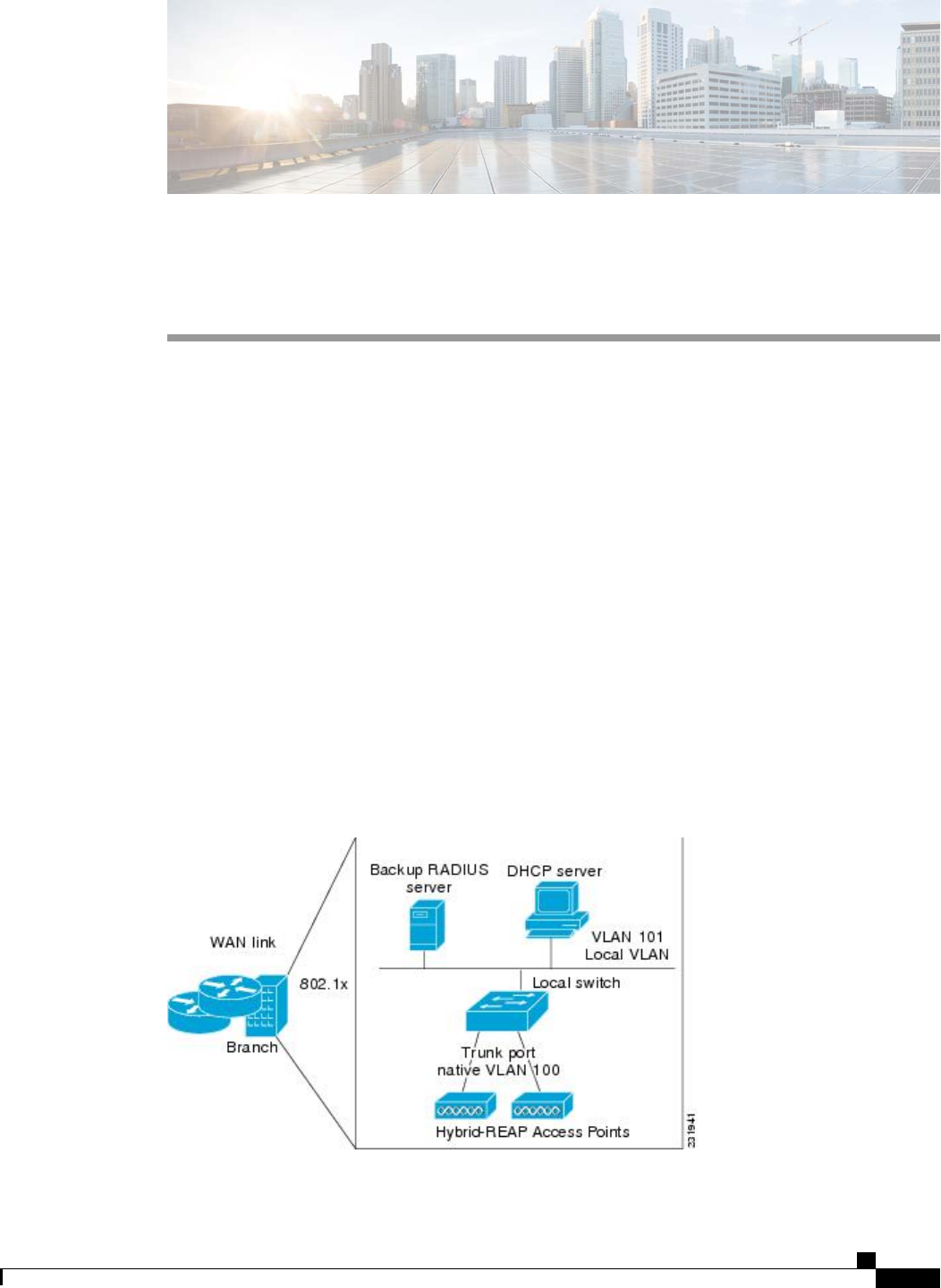
CHAPTER 139
Configuring FlexConnect Groups
•Information About FlexConnect Groups, page 915
•Configuring FlexConnect Groups, page 917
•Configuring VLAN-ACL Mapping on FlexConnect Groups, page 922
Information About FlexConnect Groups
To organize and manage your FlexConnect access points, you can create FlexConnect Groups and assign
specific access points to them.
All of the FlexConnect access points in a group share the same backup RADIUS server, CCKM, and local
authentication configuration information. This feature is helpful if you have multiple FlexConnect access
points in a remote office or on the floor of a building and you want to configure them all at once. For example,
you can configure a backup RADIUS server for a FlexConnect rather than having to configure the same server
on each access point.
The following figure shows a typical FlexConnect deployment with a backup RADIUS server in the branch
office.
Figure 68: FlexConnect Group Deployment
Cisco Wireless LAN Controller Configuration Guide, Release 7.4
OL-28744-01 915

FlexConnect Groups and Backup RADIUS Servers
You can configure the controller to allow a FlexConnect access point in standalone mode to perform full
802.1X authentication to a backup RADIUS server. You can configure a primary backup RADIUS server or
both a primary and secondary backup RADIUS server. These servers can be used when the FlexConnect
access point is in of these two modes: standalone or connected.
FlexConnect Groups and CCKM
FlexConnect Groups are required for CCKM fast roaming to work with FlexConnect access points. CCKM
fast roaming is achieved by caching a derivative of the master key from a full EAP authentication so that a
simple and secure key exchange can occur when a wireless client roams to a different access point. This feature
prevents the need to perform a full RADIUS EAP authentication as the client roams from one access point to
another. The FlexConnect access points need to obtain the CCKM cache information for all the clients that
might associate so they can process it quickly instead of sending it back to the controller. If, for example, you
have a controller with 300 access points and 100 clients that might associate, sending the CCKM cache for
all 100 clients is not practical. If you create a FlexConnect that includes a limited number of access points
(for example, you create a group for four access points in a remote office), the clients roam only among those
four access points, and the CCKM cache is distributed among those four access points only when the clients
associate to one of them.
CCKM fast roaming among FlexConnect and non-FlexConnect access points is not supported.Note
FlexConnect Groups and Opportunistic Key Caching
Starting in the 7.0.116.0 release, FlexConnect groups enable Opportunistic Key Caching (OKC) to enable
fast roaming of clients. OKC facilitates fast roaming by using PMK caching in access points that are in the
same FlexConnect group.
This feature prevents the need to perform a full authentication as the client roams from one access point to
another. Whenever a client roams from one FlexConnect access point to another, the FlexConnect group
access point calculates the PMKID using the cached PMK.
To see the PMK cache entries at the FlexConnect access point, use the show capwap reap pmk command.
This feature is supported on Cisco FlexConnect access points.
The FlexConnect access point must be in connected mode when the PMK is derived during WPA2/802.1x
authentication.
Note
When using FlexConnect groups for OKC or CCKM, the PMK-cache is shared only across the access points
that are part of the same FlexConnect group and are associated to the same controller. If the access points are
in the same FlexConnect group but are associated to different controllers that are part of the same mobility
group, the PMK cache is not updated and CCKM roaming will fail.
Cisco Wireless LAN Controller Configuration Guide, Release 7.4
916 OL-28744-01
Information About FlexConnect Groups

FlexConnect Groups and Local Authentication
You can configure the controller to allow a FlexConnect access point in standalone mode to perform LEAP,
EAP-FAST authentication for up to 100 statically configured users. The controller sends the static list of
usernames and passwords to each FlexConnect access point when it joins the controller. Each access point in
the group authenticates only its own associated clients.
This feature is ideal for customers who are migrating from an autonomous access point network to a lightweight
FlexConnect access point network and are not interested in maintaining a large user database or adding another
hardware device to replace the RADIUS server functionality available in the autonomous access point.
This feature can be used with the FlexConnect backup RADIUS server feature. If a FlexConnect is
configured with both a backup RADIUS server and local authentication, the FlexConnect access point
always attempts to authenticate clients using the primary backup RADIUS server first, followed by the
secondary backup RADIUS server (if the primary is not reachable), and finally the FlexConnect access
point itself (if the primary and secondary are not reachable).
Note
The number of FlexConnect groups and access point support depends on the platform that you are using. You
can configure the following:
•Up to 100 FlexConnect groups and 25 access points per group for a Cisco 5500 Series Controller.
•Up to 1000 FlexConnect groups and 50 access points per group for a Cisco Flex 7500 Series Controller
in the 7.2 release.
•Up to 2000 FlexConnect groups and 100 access points per group for Cisco Flex 7500 and Cisco 8500
Series Controllers in the 7.3 release.
•Up to 20 FlexConnect groups and up to 25 access points per group for the remaining platforms.
Configuring FlexConnect Groups
Configuring FlexConnect Groups (GUI)
Step 1 Choose Wireless >FlexConnect Groups to open the FlexConnect Groups page.
This page lists any FlexConnect groups that have already been created.
If you want to delete an existing group, hover your cursor over the blue drop-down arrow for that group and
choose Remove.
Note
Cisco Wireless LAN Controller Configuration Guide, Release 7.4
OL-28744-01 917
Configuring FlexConnect Groups

Step 2 Click New to create a new FlexConnect Group.
Step 3 On the FlexConnect Groups >New page, enter the name of the new group in the Group Name text box. You can
enter up to 32 alphanumeric characters.
Step 4 Click Apply. The new group appears on the FlexConnect Groups page.
Step 5 To edit the properties of a group, click the name of the desired group. The FlexConnect Groups >Edit page appears.
Step 6 If you want to configure a primary RADIUS server for this group (for example, the access points are using 802.1X
authentication), choose the desired server from the Primary RADIUS Server drop-down list. Otherwise, leave the text
box set to the default value of None.
Step 7 If you want to configure a secondary RADIUS server for this group, choose the server from the Secondary RADIUS
Server drop-down list. Otherwise, leave the field set to the default value of None.
Step 8 Configure the RADIUS server for the FlexConnect group by doing the following:
a) Enter the RADIUS server IP address.
b) Choose the server type as either Primary or Secondary.
c) Enter a shared secret to log on to the RADIUS server and confirm it.
d) Enter the port number.
e) Click Add.
Step 9 To add an access point to the group, click Add AP. Additional fields appear on the page under Add AP.
Step 10 Perform one of the following tasks:
•To choose an access point that is connected to this controller, select the Select APs from Current Controller
check box and choose the name of the access point from the AP Name drop-down list.
If you choose an access point on this controller, the MAC address of the access point is automatically
entered in the Ethernet MAC text box to prevent any mismatches from occurring.
Note
•To choose an access point that is connected to a different controller, leave the Select APs from Current Controller
check box unselected and enter its MAC address in the Ethernet MAC text box.
If the FlexConnect access points within a group are connected to different controllers, all of the controllers
must belong to the same mobility group.
Note
Step 11 Click Add to add the access point to this FlexConnect group. The access point’s MAC address, name, and status appear
at the bottom of the page.
If you want to delete an access point, hover your cursor over the blue drop-down arrow for that access point
and choose Remove.
Note
Step 12 Click Apply.
Step 13 Enable local authentication for a FlexConnect Group as follows:
a) Ensure that the Primary RADIUS Server and Secondary RADIUS Server parameters are set to None.
b) Select the Enable AP Local Authentication check box to enable local authentication for this FlexConnect Group.
The default value is unselected.
c) Click Apply.
d) Choose the Local Authentication tab to open the FlexConnect >Edit (Local Authentication > Local Users)
page.
e) To add clients that you want to be able to authenticate using LEAP, EAP-FAST, perform one of the following:
f) Upload a comma-separated values (CSV) file by selecting the Upload CSV File check box, clicking the Browse
button to browse to an CSV file that contains usernames and passwords (each line of the file needs to be in the
Cisco Wireless LAN Controller Configuration Guide, Release 7.4
918 OL-28744-01
Configuring FlexConnect Groups

following format: username, password), and clicking Add to upload the CSV file. The clients’names appear on the
left side of the page under the “User Name”heading.
g) Add clients individually by entering the client’s username in the User Name text box and a password for the client
in the Password and Confirm Password text boxes, and clicking Add to add this client to the list of supported local
users. The client name appears on the left side of the page under the “User Name”heading.
You can add up to 100
clients.
Note
h) Click Apply.
i) Choose the Protocols tab to open the FlexConnect >Edit (Local Authentication > Protocols) page.
j) To allow a FlexConnect access point to authenticate clients using LEAP, select the Enable LEAP Authentication
check box.
k) To allow a FlexConnect access point to authenticate clients using EAP-FAST, select the Enable EAP-FAST
Authentication check box. The default value is unselected.
l) Perform one of the following, depending on how you want protected access credentials (PACs) to be provisioned:
•To use manual PAC provisioning, enter the server key used to encrypt and decrypt PACs in the Server Key and
Confirm Server Key text boxes. The key must be 32 hexadecimal characters.
•To allow PACs to be sent automatically to clients that do not have one during PAC provisioning, select the
Enable Auto Key Generation check box
m) In the Authority ID text box, enter the authority identifier of the EAP-FAST server. The identifier must be 32
hexadecimal characters.
n) In the Authority Info text box, enter the authority identifier of the EAP-FAST server in text format. You can enter
up to 32 hexadecimal characters.
o) To specify a PAC timeout value, select the PAC Timeout check box and enter the number of seconds for the PAC
to remain viable in the text box. The default value is unselected, and the valid range is 2 to 4095 seconds when
enabled.
p) Click Apply.
Step 14 In the WLAN-ACL mapping tab, you can do the following:
a) Under Web Auth ACL Mapping, enter the WLAN ID, choose the WebAuth ACL, and click Add to map the web
authentication ACL and the WLAN.
b) Under Local Split ACL Mapping, enter the WLAN ID, and choose the Local Split ACL, and click Add to map the
Local Split ACL to the WLAN.
You can configure up to 16 WLAN-ACL combinations for local split tunneling. Local split tunneling does
not work for clients with static IP address.
Note
Step 15 In the Central DHCP tab, you can do the following:
a) In the WLAN Id box, enter the WLAN ID with which you want to map Central DHCP.
b) Select or unselect the Central DHCP check box to enable or disable Central DHCP for the mapping.
c) Select or unselect the Override DNS check box to enable or disable overriding of DNS for the mapping.
d) Select or unselect the NAT-PAT check box to enable or disable network address translation and port address translation
for the mapping.
e) Click Add to add the Central DHCP - WLAN mapping.
Step 16 Click Save Configuration.
Step 17 Repeat this procedure if you want to add more FlexConnects.
To see if an individual access point belongs to a FlexConnect Group, you can choose Wireless >Access Points
>All APs > the name of the desired access point in the FlexConnect tab. If the access point belongs to a
FlexConnect, the name of the group appears in the FlexConnect Name text box.
Note
Cisco Wireless LAN Controller Configuration Guide, Release 7.4
OL-28744-01 919
Configuring FlexConnect Groups

Configuring FlexConnect Groups (CLI)
Step 1 Add add or delete a FlexConnect Group by entering this command:
config flexconnect group group_name {add |delete}
Step 2 Configure a primary or secondary RADIUS server for the FlexConnect group by entering this command:
config flexconect group group-name radius server auth {{add {primary |secondary}ip-addr auth-port secret} |
{delete {primary |secondary}}}
Step 3 Add an access point to the FlexConnect Group by entering this command:
config flexconnect group_name ap {add |delete}ap_mac
Step 4 Configure local authentication for a FlexConnect as follows:
a) Make sure that a primary and secondary RADIUS server are not configured for the FlexConnect Group.
b) To enable or disable local authentication for this FlexConnect group, enter this command:
config flexconnect group group_name radius ap {enable |disable}
c) Enter the username and password of a client that you want to be able to authenticate using LEAP, EAP-FAST by
entering this command:
config flexconnect group group_name radius ap user add username password password
You can add up to 100
clients.
Note
d) Allow a FlexConnect access point group to authenticate clients using LEAP or to disable this behavior by entering
this command:
config flexconnect group group_name radius ap leap {enable |disable}
e) Allow a FlexConnect access point group to authenticate clients using EAP-FAST or to disable this behavior by
entering this command:
config flexconnect group group_name radius ap eap-fast {enable |disable}
f) To download EAP Root and Device certificate to AP, enter this command:
config flexconnect group group_name radius ap eap-cert download
g) Allow a FlexConnect access point group to authenticate clients using EAP-TLS or to disable this behavior by entering
this command:
config flexconnect group group_name radius ap eap-tls {enable |disable}
h) Allow a FlexConnect access point group to authenticate clients using PEAP or to disable this behavior by entering
this command:
config flexconnect group group_name radius ap peap {enable |disable}
i) Enter one of the following commands, depending on how you want PACs to be provisioned:
•config flexconnect group group_name radius ap server-key key—Specifies the server key used to encrypt
and decrypt PACs. The key must be 32 hexadecimal characters.
•config flexconnect group group_name radius ap server-key auto—Allows PACs to be sent automatically to
clients that do not have one during PAC provisioning.
Cisco Wireless LAN Controller Configuration Guide, Release 7.4
920 OL-28744-01
Configuring FlexConnect Groups

j) To specify the authority identifier of the EAP-FAST server, enter this command:
config flexconnect group group_name radius ap authority id id
where id is 32 hexadecimal characters.
k) To specify the authority identifier of the EAP-FAST server in text format, enter this command:
config flexconnect group group_name radius ap authority info info
where info is up to 32 hexadecimal characters.
l) To specify the number of seconds for the PAC to remain viable, enter this command:
config flexconnect group group_name radius ap pac-timeout timeout
where timeout is a value between 2 and 4095 seconds (inclusive) or 0. A value of 0, which is the default value,
disables the PAC timeout.
Step 5 Configure a Policy ACL on a FlexConnect group by entering this command:
config flexconnect group group-name acl {add |delete}acl-name
Step 6 Configure local split tunneling on a per-FlexConnect group basis by entering this command:
config flexconnect group group_name local-split wlan wlan-id acl acl-name flexconnect-group-name {enable |
disable}
Step 7 To set multicast/broadcast across L2 broadcast domain on overridden interface for locally switched clients, enter this
command:
config flexconnect group group_name multicast overridden-interface {enable |disable}
Step 8 Configure central DHCP per WLAN by entering this command:
config flexconnect group group-name central-dhcp wlan-id {enable override dns |disable |delete}
Step 9 Configure policy acl on FlexConnect group by entering this command:
config flexconnect group group_name policy acl {add |delete}acl-name
Step 10 Configure web-auth acl on flexconnect group by entering this command:
config flexconnect group group_name web-auth wlan wlan-id acl acl-name {enable |disable}
Step 11 Configure wlan-vlan mapping on flexconnect group by entering this command:
config flexconnect group group_name wlan-vlan wlan wlan-id{add |delete}vlan vlan-id
Step 12 To set efficient upgrade for group, enter this command:
config flexconnect group group_name predownload {enable |disable |master |slave}ap-name retry-count maximum
retry count ap-name ap-name
Step 13 Save your changes by entering this command:
save config
Step 14 See the current list of flexconnect groups by entering this command:
show flexconnect group summary
Step 15 See the details for a specific FlexConnect Groups by entering this command:
show flexconnect group detail group_name
Cisco Wireless LAN Controller Configuration Guide, Release 7.4
OL-28744-01 921
Configuring FlexConnect Groups

Configuring VLAN-ACL Mapping on FlexConnect Groups
Configuring VLAN-ACL Mapping on FlexConnect Groups (GUI)
Step 1 Choose Wireless >FlexConnect Groups.
The FlexConnect Groups page appears. This page lists the access points associated with the controller.
Step 2 Click the Group Name link of the FlexConnect Group for which you want to configure VLAN-ACL mapping.
Step 3 Click the VLAN-ACL Mapping tab.
The VLAN-ACL Mapping page for that FlexConnect group appears.
Step 4 Enter the Native VLAN ID in the VLAN ID text box.
Step 5 From the Ingress ACL drop-down list, choose the Ingress ACL.
Step 6 From the Egress ACL drop-down list, choose the Egress ACL.
Step 7 Click Add to add this mapping to the FlexConnect Group.
The VLAN ID is mapped with the required ACLs. To remove the mapping, hover your mouse over the blue drop-down
arrow and choose Remove.
Configuring VLAN-ACL Mapping on FlexConnect Groups (CLI)
•Add a VLAN to a FlexConnect group and map the ingress and egress ACLs by entering this command:
config flexconnect group group-name vlan add vlan-id acl ingress-acl egress acl
Viewing VLAN-ACL Mappings (CLI)
•See the FlexConnect group details by entering this command:
show flexconnect group detail group-name
•See the VLAN-ACL mappings on the access point by entering this command:
show ap config general ap-name
Cisco Wireless LAN Controller Configuration Guide, Release 7.4
922 OL-28744-01
Configuring VLAN-ACL Mapping on FlexConnect Groups

CHAPTER 140
Configuring AAA Overrides for FlexConnect
•Information About Authentication, Authorization, Accounting Overrides, page 923
•Restrictions for AAA Overrides for FlexConnect, page 924
•Configuring AAA Overrides for FlexConnect on an Access Point (GUI), page 924
•Configuring VLAN Overrides for FlexConnect on an Access Point (CLI), page 925
Information About Authentication, Authorization, Accounting Overrides
The Allow Authentication, Authorization, Accouting (AAA) Override option of a WLAN enables you to
configure the WLAN for authentication. It enables you to apply VLAN tagging, QoS, and ACLs to individual
clients based on the returned RADIUS attributes from the AAA server.
AAA overrides for FlexConnect access points introduce a dynamic VLAN assignment for locally switched
clients. AAA overrides for FlexConnect also support fast roaming (Opportunistic Key Caching [OKC]/ Cisco
Centralized Key management [CCKM]) of overridden clients.
VLAN overrides for FlexConnect are applicable for both centrally and locally authenticated clients. VLANs
can be configured on FlexConnect groups.
If a VLAN on the AP is configured using the WLAN-VLAN, the AP configuration of the corresponding ACL
is applied. If the VLAN is configured using the FlexConnect group, the corresponding ACL configured on
the FlexConnect group is applied. If the same VLAN is configured on the FlexConnect group and also on the
AP, the AP configuration, with its ACL takes precedence. If there is no slot for a new VLAN from the
WLAN-VLAN mapping, the latest configured FlexConnect group VLAN is replaced.
If the VLAN that was returned from the AAA is not present on the AP, the client falls back to the default
VLAN configured for the WLAN.
Before configuring a AAA override, the VLAN must be created on the access points. These VLANs can be
created by using the existing WLAN-VLAN mappings on the access points, or by using the FlexConnect
group VLAN-ACL mappings.
AAA Override for IPv6 ACLs
In order to support centralized access control through a centralized AAA server such as the Cisco Identity
Services Engine (ISE) or ACS, the IPv6 ACL can be provisioned on a per-client basis using AAA Override
attributes. In order to use this feature, the IPv6 ACL must be configured on the controller and the WLAN
must be configured with the AAA Override feature enabled. The AAA attribute for an IPv6 ACL is
Cisco Wireless LAN Controller Configuration Guide, Release 7.4
OL-28744-01 923

Airespace-IPv6-ACL-Name similar to the Airespace-ACL-Name attribute used for provisioning an IPv4-based
ACL. The AAA attribute-returned contents should be a string that is equal to the name of the IPv6 ACL as
configured on the controller.
Restrictions for AAA Overrides for FlexConnect
•Before configuring a AAA override, VLANs must be created on the access points. These VLANs can
be created by using the existing WLAN-VLAN mappings on the access points, or by using the
FlexConnect group VLAN-ACL mappings.
•At any given point, an AP has a maximum of 16 VLANs. First, the VLANs are selected as per the AP
configuration (WLAN-VLAN), and then the remaining VLANs are pushed from the FlexConnect group
in the order that they are configured or displayed in the FlexConnect group. If the VLAN slots are full,
an error message is displayed.
•AAA for locally switched clients supports only VLAN overrides.
•Dynamic VLAN assignment is not supported for web authentication from a controller with Access
Control Server (ACS).
Configuring AAA Overrides for FlexConnect on an Access Point (GUI)
Step 1 Choose Wireless >All >APs.
The All APs page is displayed. This page lists the access points associated with the controller.
Step 2 Click the corresponding AP name.
Step 3 Click the FlexConnect tab.
Step 4 Enter a value for Native VLAN ID.
Step 5 Click the VLAN Mappings button to configure the AP VLANs mappings.
The following parameters are displayed:
•AP Name—The access point name.
•Base Radio MAC—The base radio of the AP.
•WLAN-SSID-VLAN ID Mapping—For each WLAN configured on the controller, the corresponding SSID and
VLAN IDs are listed. Change a WLAN-VLAN ID mapping by editing the VLAN ID column for a WLAN.
•Centrally Switched WLANs—If centrally switched WLANs are configured, WLAN–VLAN mapping is listed.
•AP Level VLAN ACL Mapping—The following parameters are available:
◦VLAN ID—The VLAN ID.
◦Ingress ACL—The Ingress ACL corresponding to the VLAN.
◦Egress ACL—The Egress ACL corresponding to the VLAN.
Change the ingress ACL and egress ACL mappings by selecting the mappings from the drop-down list for each
ACL type.
Cisco Wireless LAN Controller Configuration Guide, Release 7.4
924 OL-28744-01
Restrictions for AAA Overrides for FlexConnect

•Group Level VLAN ACL Mapping—The following group level VLAN ACL mapping parameters are available:
◦VLAN ID—The VLAN ID.
◦Ingress ACL—The ingress ACL for this VLAN.
◦Egress ACL—The egress ACL for this VLAN.
Step 6 Click Apply.
Configuring VLAN Overrides for FlexConnect on an Access Point (CLI)
To configure VLAN overrides on a FlexConnect access point, use the following command:
config ap flexconnect vlan add vlan-id acl ingress-acl egress-acl ap_name
Cisco Wireless LAN Controller Configuration Guide, Release 7.4
OL-28744-01 925
Configuring VLAN Overrides for FlexConnect on an Access Point (CLI)

Cisco Wireless LAN Controller Configuration Guide, Release 7.4
926 OL-28744-01
Configuring VLAN Overrides for FlexConnect on an Access Point (CLI)

CHAPTER 141
Configuring FlexConnect AP Upgrades for
FlexConnect APs
•Information About FlexConnect AP Upgrades, page 927
•Restrictions for FlexConnect AP Upgrades for FlexConnect Access Points, page 927
•Configuring FlexConnect AP Upgrades (GUI), page 928
•Configuring FlexConnect AP Upgrades (CLI), page 928
Information About FlexConnect AP Upgrades
Normally, when upgrading the image of an AP, you can use the pre-image download feature to reduce the
amount of time the AP is unavailable to serve clients. However, it also increases the downtime because the
access point cannot serve clients during an upgrade. The Pre-image download feature can be used to reduce
this downtime. However, in the case of a branch office set up, the upgrade images are still downloaded to
each access point over the WAN link, which has a higher latency.
A more efficient way is to use the FlexConnect AP Upgrade feature. When this feature is enabled, one access
point of each model in the local network first downloads the upgrade image over the WAN link. It works
similarly to the master-slave or client-server model. This access point then becomes the master for the remaining
access point of the similar model. The remaining access points then download the upgrade image from the
master access point using the pre-image download feature over the local network, which reduces the WAN
latency.
Restrictions for FlexConnect AP Upgrades for FlexConnect Access Points
•The primary and secondary controllers in the network must have the same set of primary and backup
images.
•If you configured a FlexConnect group, all access points in that group must be within the same subnet
or must be accessible through NAT.
Cisco Wireless LAN Controller Configuration Guide, Release 7.4
OL-28744-01 927

Configuring FlexConnect AP Upgrades (GUI)
Step 1 Choose Wireless >FlexConnect Groups.
The FlexConnect Groups page appears. This page lists the FlexConnect Groups configured on the controller.
Step 2 Click the Group Name link on which you want to configure the image upgrade.
Step 3 Click the Image Upgrade tab.
Step 4 Select the FlexConnect AP Upgrade check box to enable a FlexConnect AP Upgrade.
Step 5 If you enabled the FlexConnect AP upgrade in the previous step, you must enable the following parameters:
•Slave Maximum Retry Count—The number of attempts the slave access point must try to connect to the master
access point for downloading the upgrade image. If the image download does not occur for the configured retry
attempts, the image is upgraded over the WAN.
•Upgrade Image—Select the upgrade image. The options are Primary,Backup, and Abort.
•Click FlexConnect Upgrade to upgrade.
Step 6 From the AP Name drop-down list, click Add Master to add the master access point.
You can manually assign master access points in the FlexConnect group by selecting the access points.
Step 7 Click Apply.
Configuring FlexConnect AP Upgrades (CLI)
•config flexconnect group group-name predownload {enable | disable}—Enables or disables the
FlexConnect AP upgrade.
•config flexconnect group group-name predownload master ap-name—Manually assigns an access
point as the master access point.
•config flexconnect group group-name predownload slave retry-count ap-name—Sets the access point
as a slave access point with a retry count.
•config flexconnect group group-name predownload start—Initiates the image download on the access
points in the FlexConnect group.
•config ap image predownload {abort | primary | backup}—Assigns the image type that must be
downloaded for the preimage upgrade.
•show flexconnect group group-name—Displays the summary of the FlexConnect group configuration.
•show ap image all—Displays the details of the images on the access point.
Cisco Wireless LAN Controller Configuration Guide, Release 7.4
928 OL-28744-01
Configuring FlexConnect AP Upgrades (GUI)

PART X
Configuring Mobility Groups
•Configuring Mobility Groups, page 931
•Viewing Mobility Group Statistics, page 943
•Configuring Auto-Anchor Mobility, page 945
•Validating WLAN Mobility Security Values, page 951
•Using Symmetric Mobility Tunneling, page 953
•Running Mobility Ping Tests, page 955
•Configuring Dynamic Anchoring for Clients with Static IP Addresses, page 957
•Configuring Foreign Mappings, page 961
•Configuring Proxy Mobile IPv6, page 963

CHAPTER 142
Configuring Mobility Groups
•Information About Mobility, page 931
•Information About Mobility Groups, page 935
•Prerequisites for Configuring Mobility Groups, page 938
•Configuring Mobility Groups (GUI), page 940
•Configuring Mobility Groups (CLI), page 941
Information About Mobility
Mobility, or roaming, is a wireless LAN client’s ability to maintain its association seamlessly from one access
point to another securely and with as little latency as possible. This section explains how mobility works when
controllers are included in a wireless network.
When a wireless client associates and authenticates to an access point, the access point’s controller places an
entry for that client in its client database. This entry includes the client’s MAC and IP addresses, security
context and associations, quality of service (QoS) contexts, the WLAN, and the associated access point. The
controller uses this information to forward frames and manage traffic to and from the wireless client.
Cisco Wireless LAN Controller Configuration Guide, Release 7.4
OL-28744-01 931
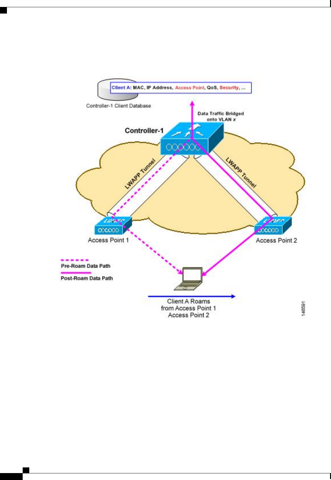
This figure shows a wireless client that roams from one access point to another when both access points are
joined to the same controller.
Figure 69: Intracontroller Roaming
When the wireless client moves its association from one access point to another, the controller simply updates
the client database with the newly associated access point. If necessary, new security context and associations
are established as well.
The process becomes more complicated, however, when a client roams from an access point joined to one
controller to an access point joined to a different controller. It also varies based on whether the controllers are
operating on the same subnet.
Cisco Wireless LAN Controller Configuration Guide, Release 7.4
932 OL-28744-01
Information About Mobility
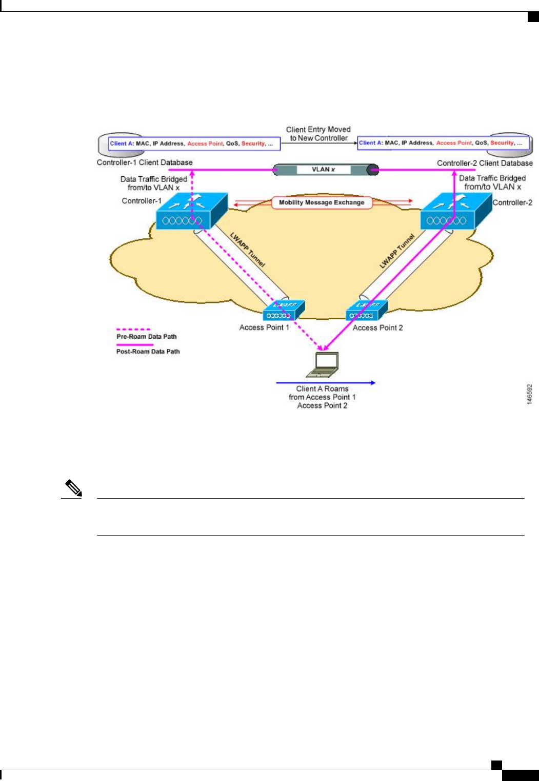
This figure shows intercontroller roaming, which occurs when the wireless LAN interfaces of the controllers
are on the same IP subnet.
Figure 70: Intercontroller Roaming
When the client associates to an access point joined to a new controller, the new controller exchanges mobility
messages with the original controller, and the client database entry is moved to the new controller. New
security context and associations are established if necessary, and the client database entry is updated for the
new access point. This process remains transparent to the user.
All clients configured with 802.1X/Wi-Fi Protected Access (WPA) security complete a full authentication
in order to comply with the IEEE standard.
Note
Cisco Wireless LAN Controller Configuration Guide, Release 7.4
OL-28744-01 933
Information About Mobility
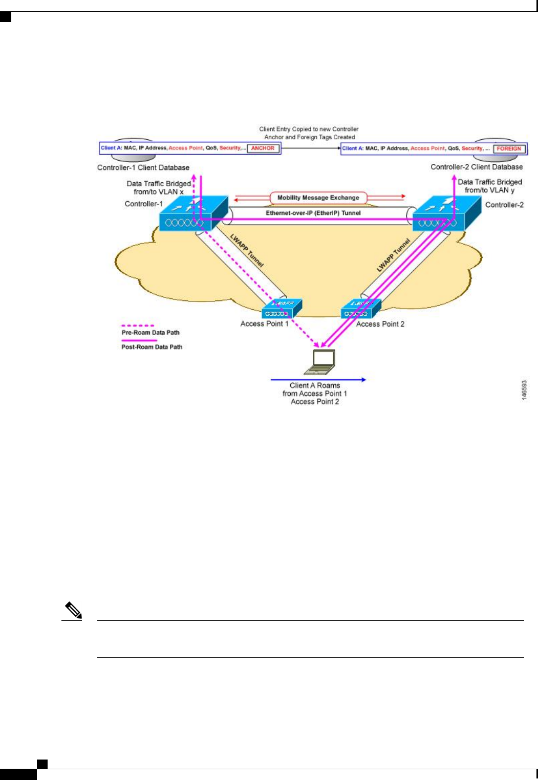
This figure shows intersubnet roaming, which occurs when the wireless LAN interfaces of the controllers are
on different IP subnets.
Figure 71: Intersubnet Roaming
Inter-subnet roaming is similar to inter-controller roaming in that the controllers exchange mobility messages
on the client roam. However, instead of moving the client database entry to the new controller, the original
controller marks the client with an “Anchor”entry in its own client database. The database entry is copied to
the new controller client database and marked with a “Foreign”entry in the new controller. The roam remains
transparent to the wireless client, and the client maintains its original IP address.
In inter-subnet roaming, WLANs on both anchor and foreign controllers need to have the same network access
privileges and no source-based routing or source-based firewalls in place. Otherwise, the clients may have
network connectivity issues after the handoff.
In a static anchor setup using controllers and ACS, if AAA override is enabled to dynamically assign VLAN
and QoS, the foreign controller updates the anchor controller with the right VLAN after a Layer 2 authentiation
(802.1x). For Layer 3 RADIUS authentication, the RADIUS requests for authentication are sent by the anchor
controller.
Mobility is not supported for SSIDs with security type configured for Webauth on MAC filter failure.
If a client roams in web authentication state, the client is considered as a new client on another controller
instead of considering it as a mobile client.
Note
Cisco Wireless LAN Controller Configuration Guide, Release 7.4
934 OL-28744-01
Information About Mobility
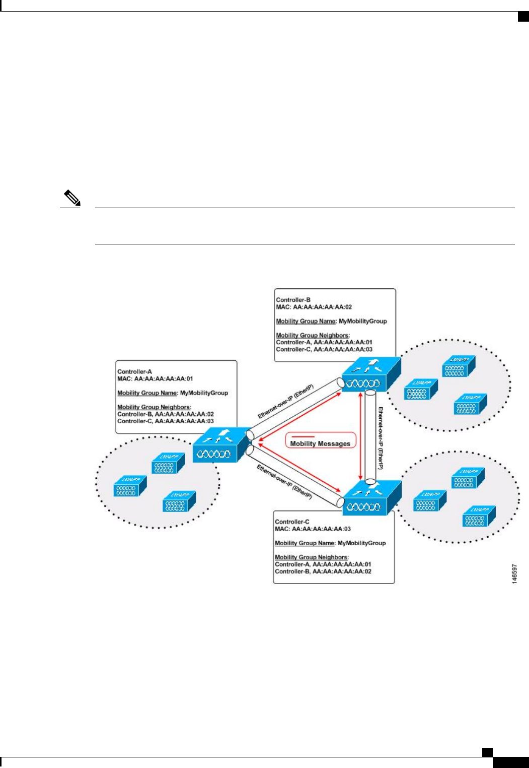
Information About Mobility Groups
A mobility group is a set of controllers, identified by the same mobility group name, that defines the realm
of seamless roaming for wireless clients. By creating a mobility group, you can enable multiple controllers
in a network to dynamically share information and forward data traffic when inter-controller or inter-subnet
roaming occurs. Controllers in the same mobility group can share the context and state of client devices as
well as their list of access points so that they do not consider each other’s access points as rogue devices. With
this information, the network can support inter-controller wireless LAN roaming and controller redundancy.
Controllers do not have to be of the same model to be a member of a mobility group. Mobility groups can
be comprised of any combination of controller platforms.
Note
Figure 72: Example of a Single Mobility Group
As shown above, each controller is configured with a list of the other members of the mobility group. Whenever
a new client joins a controller, the controller sends out a unicast message (or multicast message if mobility
multicast is configured) to all of the controllers in the mobility group. The controller to which the client was
previously connected passes on the status of the client.
For example, if a controller supports 6000 access points, a mobility group that consists of 24 such controllers
supports up to 144,000 access points (24 * 6000 = 144,000 access points).
Cisco Wireless LAN Controller Configuration Guide, Release 7.4
OL-28744-01 935
Information About Mobility Groups
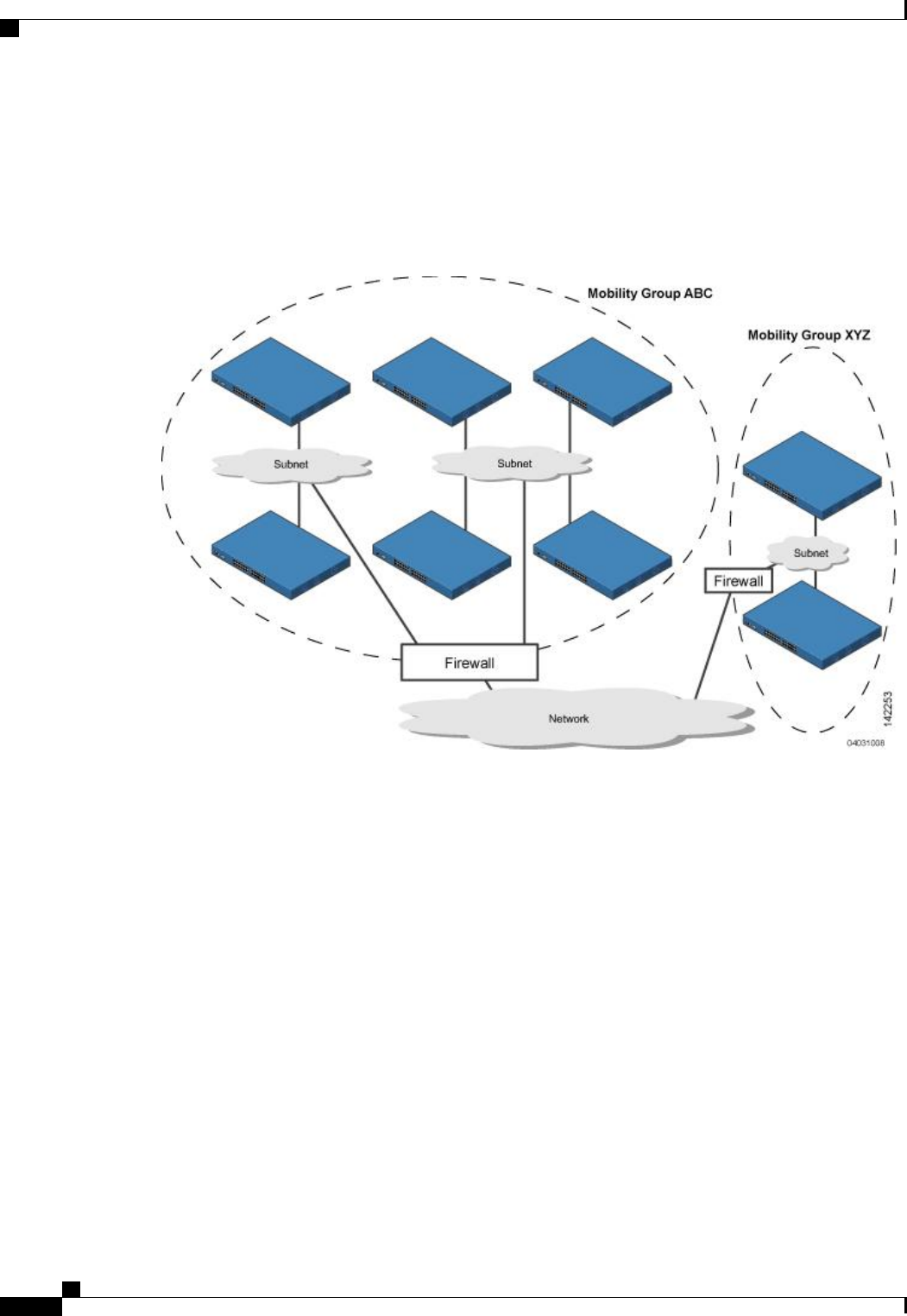
Mobility groups enable you to limit roaming between different floors, buildings, or campuses in the same
enterprise by assigning different mobility group names to different controllers within the same wireless
network.
This figure shows the results of creating distinct mobility group names for two groups of controllers.
Figure 73: Two Mobility Groups
The controllers in the ABC mobility group share access point and client information with each other. The
controllers in the ABC mobility group do not share the access point or client information with the XYZ
controllers, which are in a different mobility group. Likewise, the controllers in the XYZ mobility group do
not share access point or client information with the controllers in the ABC mobility group. This feature
ensures mobility group isolation across the network.
Every controller maintains information about its peer controllers in a mobility list. Controllers can communicate
across mobility groups and clients may roam between access points in different mobility groups if the controllers
are included in each other’s mobility lists. In the following example, controller 1 can communicate with either
controller 2 or 3, but controller 2 and controller 3 can communicate only with controller 1 and not with each
other. Similarly, clients can roam between controller 1 and controller 2 or between controller 1 and controller
3 but not between controller 2 and controller 3.
Cisco Wireless LAN Controller Configuration Guide, Release 7.4
936 OL-28744-01
Information About Mobility Groups

Table 27: Example
Controller 3
Mobility group: C
Mobility list:
Controller 1 (group A)
Controller 3 (group C)
Controller 2
Mobility group: A
Mobility list:
Controller 1 (group A)
Controller 2 (group A)
Controller 1
Mobility group: A
Mobility list:
Controller 1 (group A)
Controller 2 (group A)
Controller 3 (group C) ?
The controller supports seamless roaming across multiple mobility groups. During seamless roaming, the
client maintains its IP address across all mobility groups; however, Cisco Centralized Key Management
(CCKM) and proactive key caching (PKC) are supported only for inter-mobility-group roaming. When a
client crosses a mobility group boundary during a roam, the client is fully authenticated, but the IP address is
maintained, and mobility tunneling is initiated for Layer 3 roaming.
Messaging Among Mobility Groups
The controller provides intersubnet mobility for clients by sending mobility messages to other member
controllers.
•The controller sends a Mobile Announce message to members in the mobility list each time that a new
client associates to it. The controller sends the message only to those members that are in the same group
as the controller (the local group) and then includes all of the other members while sending retries.
•You can configure the controller to use multicast to send the Mobile Announce messages. This behavior
allows the controller to send only one copy of the message to the network, which destines it to the
multicast group that contains all the mobility members. To derive the maximum benefit from multicast
messaging, we recommend that it be enabled on all group members.
Using Mobility Groups with NAT Devices
Mobility message payloads carry IP address information about the source controller. This IP address is validated
with the source IP address of the IP header. This behavior is a problem when a NAT device is introduced in
the network because it changes the source IP address in the IP header. In the guest WLAN feature, any mobility
packet, that is being routed through a NAT device is dropped because of the IP address mismatch.
The mobility group lookup uses the MAC address of the source controller. Because the source IP address is
changed due to the mapping in the NAT device, the mobility group database is searched before a reply is sent
to get the IP address of the requesting controller. This process is done using the MAC address of the requesting
controller.
When configuring the mobility group in a network where NAT is enabled, enter the IP address that is sent to
the controller from the NAT device rather than the controller’s management interface IP address. Also, make
sure that the following ports are open on the firewall if you are using a firewall such as PIX:
•UDP 16666 for tunnel control traffic
•IP protocol 97 for user data traffic
•UDP 161 and 162 for SNMP
Cisco Wireless LAN Controller Configuration Guide, Release 7.4
OL-28744-01 937
Information About Mobility Groups

Client mobility among controllers works only if auto-anchor mobility (also called guest tunneling) or
symmetric mobility tunneling is enabled. Asymmetric tunneling is not supported when mobility controllers
are behind the NAT device. See the Configuring Auto-Anchor Mobility and Using Symmetric Mobility
Tunneling sections for details on these mobility options.
Note
Prerequisites for Configuring Mobility Groups
Before you add controllers to a mobility group, you must verify that the following requirements have been
met for all controllers that are to be included in the group:
•IP connectivity must exist between the management interfaces of all controllers.
You can verify IP connectivity by pinging the controllers.Note
Mobility control packets can use any interface address as the source, based on routing
table. It is recommended that all controllers in the mobility group should have the
management interface in the same subnet. A topology where one controller's management
interface and other controller's dynamic interface are on same subnet not recommended
for seamless mobility.
Note
•When controllers in the mobility list use different software versions, Layer 2 or Layer 3 clients have
limited roaming support. Layer 2 or Layer 3 client roaming is supported only between controllers that
use the same version or with controllers that run versions 7.X.X.
If you inadvertently configure a controller with a failover controller that runs a different
software release, the access point might take a long time to join the failover controller
because the access point starts the discovery process in CAPWAP and then changes to
LWAPP discovery.
Note
•All controllers must be configured with the same virtual interface IP address.
If necessary, you can change the virtual interface IP address by editing the virtual
interface name on the Controller > Interfaces page.
Note
If all the controllers within a mobility group are not using the same virtual interface,
inter-controller roaming may appear to work, but the handoff does not complete, and
the client loses connectivity for a period of time.
Note
Cisco Wireless LAN Controller Configuration Guide, Release 7.4
938 OL-28744-01
Prerequisites for Configuring Mobility Groups

•You must have gathered the MAC address and IP address of every controller that is to be included in
the mobility group. This information is necessary because you will be configuring all controllers with
the MAC address and IP address of all the other mobility group members.
You can find the MAC and IP addresses of the other controllers to be included in the
mobility group on the Controller > Mobility Groups page of each controller’s GUI.
Note
•When you configure mobility groups using a third-party firewall, for example, Cisco PIX, or Cisco ASA,
you must open port 16666, and IP protocol 97.
•For intercontroller CAPWAP data and control traffic, you must open the ports 5247 and 5264.
This table lists the protocols and port numbers that must be used for management and operational purposes:
Table 28: Protocol/Service and Port Number
Port NumberProtocol/Service
TCP Port 22 or 29SSH/Telnet
UDP Port 69TFTP
UDP Port 123NTP
UDP Port 161 for gets and sets and UDP port 162 for traps.SNMP
TCP port 443 for HTTPS and port 80 for HTTPHTTPS/HTTP
TCP port 514Syslog
UDP port 1812 and 1813Radius Auth/Account
To view information on mobility support across controllers with different software versions, see the Cisco
Wireless Solutions Software Compatibility Matrix.
Note
You cannot perform port address translation (PAT) on the firewall. You must configure one-to-one network
address translation (NAT).
Note
Cisco Wireless LAN Controller Configuration Guide, Release 7.4
OL-28744-01 939
Prerequisites for Configuring Mobility Groups

Configuring Mobility Groups (GUI)
Step 1 Choose Controller > Mobility Management > Mobility Groups to open the Static Mobility Group Members page.
This page shows the mobility group name in the Default Mobility Group text box and lists the MAC address and IP
address of each controller that is currently a member of the mobility group. The first entry is the local controller, which
cannot be deleted.
If you want to delete any of the remote controllers from the mobility group, hover your cursor over the blue
drop-down arrow for the desired controller and choose Remove.
Note
Step 2 Perform one of the following to add controllers to a mobility group:
•If you are adding only one controller or want to individually add multiple controllers, click New and go.
OR
•If you are adding multiple controllers and want to add them in bulk, click EditAll and go to.
The EditAll option enables you to enter the MAC and IP addresses of all the current mobility group members
and then copy and paste all the entries from one controller to the other controllers in the mobility group.
Note
Step 3 Click New to open the Mobility Group Member > New page.
Step 4 Add a controller to the mobility group as follows:
1In the Member IP Address text box, enter the management interface IP address of the controller to be added.
If you are configuring the mobility group in a network where network address translation (NAT) is enabled,
enter the IP address that is sent to the controller from the NAT device rather than the controller’s management
interface IP address. Otherwise, mobility will fail among controllers in the mobility group.
Note
2In the Member MAC Address text box, enter the MAC address of the controller to be added.
3In the Group Name text box, enter the name of the mobility group.
The mobility group name is case
sensitive.
Note
4In the Hash text box, enter the hash key of the peer mobility controller, which should be a virtual controller in the
same domain.
You must configure the hash only if the peer mobility controller is a virtual controller in the same domain.
5Click Apply to commit your changes. The new controller is added to the list of mobility group members on the Static
Mobility Group Members page.
6Click Save Configuration to save your changes.
7Repeat Step a through Step e to add all of the controllers in the mobility group.
8Repeat this procedure on every controller to be included in the mobility group. All controllers in the mobility group
must be configured with the MAC address and IP address of all other mobility group members.
The Mobility Group Members > Edit All page lists the MAC address, IP address, and mobility group name (optional)
of all the controllers currently in the mobility group. The controllers are listed one per line with the local controller at
the top of the list.
If desired, you can edit or delete any of the controllers in the
list.
Note
Cisco Wireless LAN Controller Configuration Guide, Release 7.4
940 OL-28744-01
Configuring Mobility Groups (GUI)

Step 5 Add more controllers to the mobility group as follows:
1Click inside the edit box to start a new line.
2Enter the MAC address, the management interface IP address, and the name of the mobility group for the controller
to be added.
You should enter these values on one line and separate each value with one or two
spaces.
Note
The mobility group name is case
sensitive.
Note
3Repeat Step a and Step b for each additional controller that you want to add to the mobility group.
4Highlight and copy the complete list of entries in the edit box.
5Click Apply to commit your changes. The new controllers are added to the list of mobility group members on the
Static Mobility Group Members page.
6Click Save Configuration to save your changes.
7Paste the list into the text box on the Mobility Group Members > Edit All page of all the other controllers in the
mobility group and click Apply and Save Configuration.
Step 6 Choose Multicast Messaging to open the Mobility Multicast Messaging page.
The names of all the currently configured mobility groups appear in the middle of the page.
Step 7 On the Mobility Multicast Messaging page, select the Enable Multicast Messaging check box to enable the controller
to use multicast mode to send Mobile Announce messages to the mobility members. If you leave it unselected, the
controller uses unicast mode to send the Mobile Announce messages. The default value is unselected.
Step 8 If you enabled multicast messaging in the previous step, enter the multicast group IP address for the local mobility group
in the Local Group Multicast IP Address text box. This address is used for multicast mobility messaging.
In order to use multicast messaging, you must configure the IP address for the local mobility
group.
Note
Step 9 Click Apply to commit your changes.
Step 10 If desired, you can also configure the multicast group IP address for nonlocal groups within the mobility list. To do so,
click the name of a nonlocal mobility group to open the Mobility Multicast Messaging > Edit page, and enter the multicast
group IP address for the nonlocal mobility group in the Multicast IP Address text box.
If you do not configure the multicast IP address for nonlocal groups, the controller uses unicast mode to send
mobility messages to those members.
Note
Step 11 Click Apply to commit your changes.
Step 12 Click Save Configuration to save your changes.
Configuring Mobility Groups (CLI)
Step 1 Check the current mobility settings by entering this command:
show mobility summary
Cisco Wireless LAN Controller Configuration Guide, Release 7.4
OL-28744-01 941
Configuring Mobility Groups (CLI)

Step 2 Create a mobility group by entering this command:
config mobility group domain domain_name
Enter up to 31 case-sensitive ASCII characters for the group name. Spaces are not allowed in mobility group
names.
Note
Step 3 Add a group member by entering this command:
config mobility group member add mac_address ip_address
If you are configuring the mobility group in a network where network address translation (NAT) is enabled,
enter the IP address that is sent to the controller from the NAT device rather than the controller’s management
interface IP address. Otherwise, mobility will fail among controllers in the mobility group.
Note
Enter the config mobility group member delete mac_address command if you want to delete a group member.
Note
Step 4 To configure the hash key of a peer mobility controller, which is a virtual controller in the same domain, enter this
command:
config mobility group member hash peer-ip-address key
Step 5 Enable or disable multicast mobility mode by entering this command:
config mobility multicast-mode {enable |disable}local_group_multicast_address
where local_group_multicast_address is the multicast group IP address for the local mobility group. This address is used
for multicast mobility messaging.
If you enable multicast mobility mode, the controller uses multicast mode to send Mobile Announce messages to the
local group. If you disable multicast mobility mode, the controller uses unicast mode to send the Mobile Announce
messages to the local group. The default value is disabled.
Step 6 (Optional) You can also configure the multicast group IP address for nonlocal groups within the mobility list. To do so,
enter this command:
config mobility group multicast-address group_name IP_address
If you do not configure the multicast IP address for nonlocal groups, the controller uses unicast mode to send mobility
messages to those members.
Step 7 Verify the mobility configuration by entering this command:
show mobility summary
Step 8 To see the hash key of mobility group members in the same domain, enter this command:
show mobility group member hash
Step 9 Save your changes by entering this command:
save config
Step 10 Repeat this procedure on every controller to be included in the mobility group. All controllers in the mobility group must
be configured with the MAC address and IP address of all other mobility group members.
Step 11 Enable or disable debugging of multicast usage for mobility messages by entering this command:
debug mobility multicast {enable |disable}
Cisco Wireless LAN Controller Configuration Guide, Release 7.4
942 OL-28744-01
Configuring Mobility Groups (CLI)

CHAPTER 143
Viewing Mobility Group Statistics
•Viewing Mobility Group Statistics (GUI), page 943
•Viewing Mobility Group Statistics (CLI), page 944
Viewing Mobility Group Statistics (GUI)
Step 1 Choose Monitor > Statistics > Mobility Statistics to open the Mobility Statistics page.
This page contains the following fields
•Group Mobility Statistics
◦Rx Errors—Generic protocol packet receive errors, such as packet too short or format incorrect.
◦Tx Errors—Generic protocol packet transmit errors, such as packet transmission fail.
◦Responses Retransmitted—Mobility protocol that uses UDP and resends requests several times if it does not
receive a response. Because of network or processing delays, the responder may receive one or more retry
requests after it initially responds to a request. This text box shows a count of the response resends.
◦Handoff Requests Received—Total number of handoff requests received, ignored, or responded to.
◦Handoff End Requests Received—Total number of handoff end requests received. These requests are sent
by the anchor or foreign controller to notify the other about the close of a client session.
◦State Transitions Disallowed—Policy enforcement module (PEM) that has denied a client state transition,
usually resulting in the handoff being aborted.
◦Resource Unavailable—Necessary resource, such as a buffer, was unavailable, resulting in the handoff being
aborted.
•Mobility Initiator Statistics
◦Handoff Requests Sent—Number of clients that have associated to the controller and have been announced
to the mobility group.
◦Handoff Replies Received—Number of handoff replies that have been received in response to the requests
sent.
Cisco Wireless LAN Controller Configuration Guide, Release 7.4
OL-28744-01 943

◦Handoff as Local Received—Number of handoffs in which the entire client session has been transferred.
◦Handoff as Foreign Received—Number of handoffs in which the client session was anchored elsewhere.
◦Handoff Denys Received—Number of handoffs that were denied.
◦Anchor Request Sent—Number of anchor requests that were sent for a three-party (foreign-to-foreign) handoff.
The handoff was received from another foreign controller, and the new controller is requesting the anchor to
move the client.
◦Anchor Deny Received—Number of anchor requests that were denied by the current anchor.
◦Anchor Grant Received—Number of anchor requests that were approved by the current anchor.
◦Anchor Transfer Received—Number of anchor requests that closed the session on the current anchor and
transferred the anchor back to the requestor.
•Mobility Responder Statistics
◦Handoff Requests Ignored—Number of handoff requests or client announcements that were ignored because
the controller had no knowledge of that client.
◦Ping Pong Handoff Requests Dropped—Number of handoff requests that were denied because the handoff
period was too short (3 seconds).
◦Handoff Requests Dropped—Number of handoff requests that were dropped due to either an incomplete
knowledge of the client or a problem with the packet.
◦Handoff Requests Denied—Number of handoff requests that were denied.
◦Client Handoff as Local—Number of handoff responses sent while the client is in the local role.
◦Client Handoff as Foreign—Number of handoff responses sent while the client is in the foreign role.
◦Anchor Requests Received—Number of anchor requests received.
◦Anchor Requests Denied—Number of anchor requests denied.
◦Anchor Requests Granted—Number of anchor requests granted.
◦Anchor Transferred—Number of anchors transferred because the client has moved from a foreign controller
to a controller on the same subnet as the current anchor.
Step 2 If you want to clear the current mobility statistics, click Clear Stats.
Viewing Mobility Group Statistics (CLI)
•See mobility group statistics by entering the show mobility statistics command.
•To clear the current mobility statistics, enter the clear stats mobility command.
Cisco Wireless LAN Controller Configuration Guide, Release 7.4
944 OL-28744-01
Viewing Mobility Group Statistics (CLI)

CHAPTER 144
Configuring Auto-Anchor Mobility
•Information About Auto-Anchor Mobility, page 945
•Guidelines and Limitations, page 946
•Configuring Auto-Anchor Mobility (GUI), page 947
•Configuring Auto-Anchor Mobility (CLI), page 947
Information About Auto-Anchor Mobility
You can use auto-anchor mobility (also called guest tunneling) to improve load balancing and security for
roaming clients on your wireless LANs. Under normal roaming conditions, client devices join a wireless LAN
and are anchored to the first controller that they contact. If a client roams to a different subnet, the controller
to which the client roamed sets up a foreign session for the client with the anchor controller. However, when
you use the auto-anchor mobility feature, you can specify a controller or set of controllers as the anchor points
for clients on a wireless LAN.
In auto-anchor mobility mode, a subset of a mobility group is specified as the anchor controllers for a WLAN.
You can use this feature to restrict a WLAN to a single subnet, regardless of a client’s entry point into the
network. Clients can then access a guest WLAN throughout an enterprise but still be restricted to a specific
subnet. Auto-anchor mobility can also provide geographic load balancing because the WLANs can represent
a particular section of a building (such as a lobby, a restaurant, and so on), effectively creating a set of home
controllers for a WLAN. Instead of being anchored to the first controller that they happen to contact, mobile
clients can be anchored to controllers that control access points in a particular vicinity.
When a client first associates to a controller of a mobility group that has been preconfigured as a mobility
anchor for a WLAN, the client associates to the controller locally, and a local session is created for the client.
Clients can be anchored only to preconfigured anchor controllers of the WLAN. For a given WLAN, you
should configure the same set of anchor controllers on all controllers in the mobility group.
When a client first associates to a controller of a mobility group that has not been configured as a mobility
anchor for a WLAN, the client associates to the controller locally, a local session is created for the client, and
the client is announced to the other controllers in the mobility list. If the announcement is not answered, the
controller contacts one of the anchor controllers configured for the WLAN and creates a foreign session for
the client on the local switch. Packets from the client are encapsulated through a mobility tunnel using EtherIP
and sent to the anchor controller, where they are decapsulated and delivered to the wired network. Packets to
the client are received by the anchor controller and forwarded to the foreign controller through a mobility
tunnel using EtherIP. The foreign controller decapsulates the packets and forwards them to the client.
Cisco Wireless LAN Controller Configuration Guide, Release 7.4
OL-28744-01 945

If multiple controllers are added as mobility anchors for a particular WLAN on a foreign controller, the foreign
controller internally sorts the controller by their IP address. The controller with the lowest IP address is the
first anchor. For example, a typical ordered list would be 172.16.7.25, 172.16.7.28, 192.168.5.15. If the first
client associates to the foreign controller's anchored WLAN, the client database entry is sent to the first anchor
controller in the list, the second client is sent to the second controller in the list, and so on, until the end of
the anchor list is reached. The process is repeated starting with the first anchor controller. If any of the anchor
controller is detected to be down, all the clients anchored to the controller are deauthenticated, and the clients
then go through the authentication/anchoring process again in a round-robin manner with the remaining
controller in the anchor list. This functionality is also extended to regular mobility clients through mobility
failover. This feature enables mobility group members to detect failed members and reroute clients.
Guidelines and Limitations
•Mobility list members can send ping requests to one another to check the data and control paths among
them to find failed members and reroute clients. You can configure the number and interval of ping
requests that are sent to each anchor controller. This functionality provides guest N+1 redundancy for
guest tunneling and mobility failover for regular mobility.
•You must add controllers to the mobility group member list before you can designate them as mobility
anchors for a WLAN.
•You can configure multiple controllers as mobility anchors for a WLAN.
•Auto-anchor mobility supports web authentication but does not support other Layer 3 security types.
•You must configure the WLANs on both the foreign controller and the anchor controller with mobility
anchors. On the anchor controller, configure the anchor controller itself as a mobility anchor. On the
foreign controller, configure the anchor as a mobility anchor.
•Auto-anchor mobility is not supported for use with DHCP option 82.
•When using the guest N+1 redundancy and mobility failover features with a firewall, make sure that the
following ports are open:
◦UDP 16666 for tunnel control traffic
◦IP Protocol 97 for user data traffic
◦UDP 161 and 162 for SNMP
•A client, when it moves from anchor controller to foreign controller, sends th
•In case of roaming between anchor controller and foreign mobility, the client addresses learned at the
anchor controller is shown at the foreign controller. You must check the foreign controller to view the
RA throttle statistics.
•For Layer 3 RADIUS authentication, the RADIUS requests for authentication are sent by the anchor
controller.
Cisco Wireless LAN Controller Configuration Guide, Release 7.4
946 OL-28744-01
Guidelines and Limitations

Configuring Auto-Anchor Mobility (GUI)
Step 1 Configure the controller to detect failed anchor controllers within a mobility group as follows:
a) Choose Controller >Mobility Management >Mobility Anchor Config to open the Mobility Anchor Config page.
b) In the Keep Alive Count text box, enter the number of times a ping request is sent to an anchor controller before the
anchor is considered to be unreachable. The valid range is 3 to 20, and the default value is 3.
c) In the Keep Alive Interval text box, enter the amount of time (in seconds) between each ping request that is sent to
an anchor controller. The valid range is 1 to 30 seconds, and the default value is 10 seconds.
d) In the DSCP Value text box, enter the DSCP value. The default is 0.
e) Click Apply to commit your changes.
Step 2 Choose WLANs to open the WLANs page.
Step 3 Click the blue drop-down arrow for the desired WLAN or wired guest LAN and choose Mobility Anchors. The Mobility
Anchors page appears.
This page lists the controllers that have already been configured as mobility anchors and shows the current state of their
data and control paths. Controllers within a mobility group communicate among themselves over a well-known UDP
port and exchange data traffic through an Ethernet-over-IP (EoIP) tunnel. They send mpings, which test mobility control
packet reachability over the management interface over mobility UDP port 16666 and they send epings, which test the
mobility data traffic over the management interface over EoIP port 97. The Control Path text box shows whether mpings
have passed (up) or failed (down), and the Data Path text box shows whether epings have passed (up) or failed (down).
If the Data or Control Path text box shows “down,”the mobility anchor cannot be reached and is considered failed.
Step 4 Select the IP address of the controller to be designated a mobility anchor in the Switch IP Address (Anchor) drop-down
list.
Step 5 Click Mobility Anchor Create. The selected controller becomes an anchor for this WLAN or wired guest LAN.
To delete a mobility anchor for a WLAN or wired guest LAN, hover your cursor over the blue drop-down arrow
for the anchor and choose Remove.
Note
Step 6 Click Save Configuration.
Step 7 Repeat Step 4 and Step 6 to set any other controllers as mobility anchors for this WLAN or wired guest LAN.
Step 8 Configure the same set of mobility anchors on every controller in the mobility group.
Configuring Auto-Anchor Mobility (CLI)
•The controller is programmed to always detect failed mobility list members. To change the parameters
for the ping exchange between mobility members, enter these commands:
◦config mobility group keepalive count count—Specifies the number of times a ping request is
sent to a mobility list member before the member is considered to be unreachable. The valid range
is 3 to 20, and the default value is 3.
◦config mobility group keepalive interval seconds—Specifies the amount of time (in seconds)
between each ping request sent to a mobility list member. The valid range is 1 to 30 seconds, and
the default value is 10 seconds.
Cisco Wireless LAN Controller Configuration Guide, Release 7.4
OL-28744-01 947
Configuring Auto-Anchor Mobility (GUI)

•Disable the WLAN or wired guest LAN for which you are configuring mobility anchors by entering
this command:
config {wlan | guest-lan} disable {wlan_id | guest_lan_id}
•Create a new mobility anchor for the WLAN or wired guest LAN by entering one of these commands:
◦config mobility group anchor add {wlan | guest-lan} {wlan_id | guest_lan_id}
anchor_controller_ip_address
◦config {wlan | guest-lan}mobility anchor add {wlan_id | guest_lan_id}
anchor_controller_ip_address
The wlan_id or guest_lan_id must exist and be disabled, and the
anchor_controller_ip_address must be a member of the default mobility group.
Note
Auto-anchor mobility is enabled for the WLAN or wired guest LAN when you configure
the first mobility anchor.
Note
•Delete a mobility anchor for the WLAN or wired guest LAN by entering one of these commands:
◦config mobility group anchor delete {wlan | guest-lan} {wlan_id | guest_lan_id}
anchor_controller_ip_address
◦config {wlan | guest-lan} mobility anchor delete {wlan_id | guest_lan_id}
anchor_controller_ip_address
The wlan_id or guest_lan_id must exist and be disabled.
Note
Deleting the last anchor disables the auto-anchor mobility feature and resumes normal
mobility for new associations.
Note
•Save your settings by entering this command:
save config
•See a list and status of controllers configured as mobility anchors for a specific WLAN or wired guest
LAN by entering this command:
show mobility anchor {wlan |guest-lan} {wlan_id |guest_lan_id}
Cisco Wireless LAN Controller Configuration Guide, Release 7.4
948 OL-28744-01
Configuring Auto-Anchor Mobility (CLI)

The wlan_id and guest_lan_id parameters are optional and constrain the list to the
anchors in a particular WLAN or guest LAN. To see all of the mobility anchors on your
system, enter the show mobility anchor command.
The Status text box shows one of these values:
UP—The controller is reachable and able to pass data.
CNTRL_PATH_DOWN—The mpings failed. The controller cannot be reached through
the control path and is considered failed.
DATA_PATH_DOWN—The epings failed. The controller cannot be reached and is
considered failed.
CNTRL_DATA_PATH_DOWN—Both the mpings and epings failed. The controller
cannot be reached and is considered failed.
Note
•See the status of all mobility group members by entering this command:
show mobility summary
•Troubleshoot mobility issues by entering these commands:
◦debug mobility handoff {enable |disable}—Debugs mobility handoff issues.
◦debug mobility keep-alive {enable |disable}all—Dumps the keepalive packets for all mobility
anchors.
◦debug mobility keep-alive {enable |disable}IP_address—Dumps the keepalive packets for a
specific mobility anchor.
Cisco Wireless LAN Controller Configuration Guide, Release 7.4
OL-28744-01 949
Configuring Auto-Anchor Mobility (CLI)

Cisco Wireless LAN Controller Configuration Guide, Release 7.4
950 OL-28744-01
Configuring Auto-Anchor Mobility (CLI)

CHAPTER 145
Validating WLAN Mobility Security Values
•Information About WLAN Mobility Security Values, page 951
Information About WLAN Mobility Security Values
For any anchoring or mobility event, the WLAN security policy values on each controller must match. These
values can be validated in the controller debugs. This table lists the WLAN mobility security values and their
corresponding security policy.
Table 29: WLAN Mobility Security Values
Security PolicySecurity Hexadecimal Value
Security_None0x00000000
Security_WEP0x00000001
Security_802_1X0x00000002
Security_IPSec*0x00000004
Security_IPSec_Passthrough*0x00000008
Security_Web0x00000010
Security_PPTP*0x00000020
Security_DHCP_Required0x00000040
Security_WPA_NotUsed0x00000080
Security_Cranite_Passthrough*0x00000100
Security_Fortress_Passthrough*0x00000200
Security_L2TP_IPSec*0x00000400
Cisco Wireless LAN Controller Configuration Guide, Release 7.4
OL-28744-01 951

Security PolicySecurity Hexadecimal Value
Security_802_11i_NotUsed
Controllers running software release 6.0 or later do
not support this security policy.
Note
0x00000800
Security_Web_Passthrough0x00001000
Cisco Wireless LAN Controller Configuration Guide, Release 7.4
952 OL-28744-01
Information About WLAN Mobility Security Values
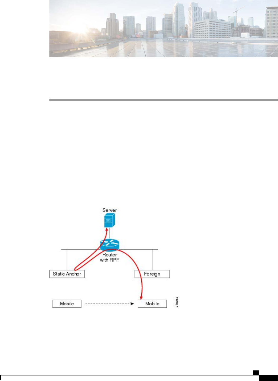
CHAPTER 146
Using Symmetric Mobility Tunneling
•Information About Symmetric Mobility Tunneling, page 953
•Guidelines and Limitations, page 954
•Verifying Symmetric Mobility Tunneling (GUI), page 954
•Verifying if Symmetric Mobility Tunneling is Enabled (CLI), page 954
Information About Symmetric Mobility Tunneling
When symmetric mobility tunneling is enabled, all client traffic is sent to the anchor controller and can then
successfully pass the RPF check.
Figure 74: Symmetric Mobility Tunneling or Bi-Directional Tunneling
Symmetric mobility tunneling is also useful in the following situations:
•If a firewall installation in the client packet path drops packets because the source IP address does not
match the subnet on which the packets are received.
Cisco Wireless LAN Controller Configuration Guide, Release 7.4
OL-28744-01 953

•If the access-point group VLAN on the anchor controller is different than the WLAN interface VLAN
on the foreign controller. In this case, client traffic could be sent on an incorrect VLAN during mobility
events.
Guidelines and Limitations
•Symmetric mobility tunneling is enabled by default.
Verifying Symmetric Mobility Tunneling (GUI)
Step 1 Choose Controller >Mobility Management >Mobility Anchor Config to open the Mobility Anchor Config page.
Step 2 The Symmetric Mobility Tunneling Mode text box shows Enabled.
Verifying if Symmetric Mobility Tunneling is Enabled (CLI)
Verify that symmetric mobility tunneling is enabled by entering this command:
show mobility summary
Cisco Wireless LAN Controller Configuration Guide, Release 7.4
954 OL-28744-01
Guidelines and Limitations

CHAPTER 147
Running Mobility Ping Tests
•Information About Mobility Ping Tests, page 955
•Guidelines and Limitations, page 955
•Running Mobility Ping Tests (CLI), page 956
Information About Mobility Ping Tests
Controllers in a mobility list communicate with each other by controlling information over a well-known
UDP port and exchanging data traffic through an Ethernet-over-IP (EoIP) tunnel. Because UDP and EoIP are
not reliable transport mechanisms, there is no guarantee that a mobility control packet or data packet will be
delivered to a mobility peer. Mobility packets may be lost in transit due to a firewall filtering the UDP port
or EoIP packets or due to routing issues.
Guidelines and Limitations
Controller software release 4.0 or later releases enable you to test the mobility communication environment
by performing mobility ping tests. These tests may be used to validate connectivity between members of a
mobility group (including guest controllers). Two ping tests are available:
•Mobility ping over UDP—This test runs over mobility UDP port 16666. It tests whether the mobility
control packet can be reached over the management interface.
•Mobility ping over EoIP—This test runs over EoIP. It tests the mobility data traffic over the management
interface.
Only one mobility ping test per controller can be run at a given time.
These ping tests are not Internet Control Message Protocol (ICMP) based. The term “ping”is used to
indicate an echo request and an echo reply message.
Note
Cisco Wireless LAN Controller Configuration Guide, Release 7.4
OL-28744-01 955

Any ICMP packet greater than 1280 bytes will always be responded with a packet that is truncated to
1280 bytes. For example, a ping with a packet that is greater than 1280 bytes from a host to the management
interface is always responded with a packet that is truncated to 1280 bytes.
Note
Running Mobility Ping Tests (CLI)
•To test the mobility UDP control packet communication between two controllers, enter this command:
mping mobility_peer_IP_address
The mobility_peer_IP_address parameter must be the IP address of a controller that belongs to the
mobility list.
•To test the mobility EoIP data packet communication between two controllers, enter this command:
eping mobility_peer_IP_address
The mobility_peer_IP_address parameter must be the IP address of a controller that belongs to the
mobility list.
•To troubleshoot your controller for mobility ping, enter these commands:
config logging buffered debugging
show logging
To troubleshoot your controller for mobility ping over UDP, enter this command to display the mobility
control packet:
debug mobility handoff enable
We recommend using an ethereal trace capture when troubleshooting.Note
Cisco Wireless LAN Controller Configuration Guide, Release 7.4
956 OL-28744-01
Running Mobility Ping Tests (CLI)

CHAPTER 148
Configuring Dynamic Anchoring for Clients with
Static IP Addresses
•Information About Dynamic Anchoring for Clients with Static IP, page 957
•Guidelines and Limitations, page 958
•Configuring Dynamic Anchoring of Static IP Clients (GUI), page 958
•Configuring Dynamic Anchoring of Static IP Clients (CLI), page 959
Information About Dynamic Anchoring for Clients with Static IP
At times you may want to configure static IP addresses for wireless clients. When these wireless clients move
about in a network, they could try associating with other controllers. If the clients try to associate with a
controller that does not support the same subnet as the static IP, the clients fail to connect to the network. You
can now enable dynamic tunneling of clients with static IP addresses.
Dynamic anchoring of static IP clients with static IP addresses can be associated with other controllers where
the client’s subnet is supported by tunneling the traffic to another controller in the same mobility group. This
feature enables you to configure your WLAN so that the network is serviced even though the clients use static
IP addresses.
How Dynamic Anchoring of Static IP Clients Works
The following sequence of steps occur when a client with a static IP address tries to associate with a controller:
1When a client associates with a controller, for example, WLC-1, it performs a mobility announcement. If
a controller in the mobility group responds (for example WLC-2), the client traffic is tunneled to the
controller WLC-2. As a result, the controller WLC 1 becomes the foreign controller and WLC-2 becomes
the anchor controller.
2If none of the controllers responds, the client is treated as a local client and authentication is performed.
The IP address for the client is updated either through an orphan packet handling or an ARP request
processing. If the IP subnet of the client is not supported in the controller (WLC-1), WLC-1 sends another
static IP mobile announce and if a controller (for example WLC-3) that supports the client's subnet responds
to that announcement, the client traffic is tunneled to that controller, that is WLC-3. As a result, the
controller WLC 1 becomes the export foreign controller and WLC-3 becomes the export anchor controller.
Cisco Wireless LAN Controller Configuration Guide, Release 7.4
OL-28744-01 957

3Once the acknowledgement is received, the client traffic is tunneled between the anchor and the controller
(WLC-1).
If you configure WLAN with an interface group and any of the interfaces in the interface group supports
the static IP client subnet, the client is assigned to that interface. This situation occurs in local or remote
(static IP Anchor) controller.
Note
A security level 2 authentication is performed only in the local (static IP foreign) controller, which is also
known as the exported foreign controller.
Note
Guidelines and Limitations
•Do not configure overridden interfaces when you perform AAA for static IP tunneling, this is because
traffic can get blocked for the client if the overridden interface does not support the client’s subnet. This
can be possible in extreme cases where the overriding interface group supports the client’s subnet.
•The local controller must be configured with the correct AAA server where this client entry is present.
The following restrictions apply when configuring static IP tunneling with other features on the same WLAN:
•Auto anchoring mobility (guest tunneling) cannot be configured for the same WLAN.
•FlexConnect local authentication cannot be configured for the same WLAN.
•The DHCP required option cannot be configured for the same WLAN.
•You cannot configure dynamic anchoring of static IP clients with FlexConnect local switching.
Configuring Dynamic Anchoring of Static IP Clients (GUI)
Step 1 Choose WLANs to open the WLANs page.
Step 2 Click the ID number of the WLAN on which you want to enable dynamic anchoring of IP clients. The WLANs > Edit
page is displayed.
Step 3 Choose the Advanced tab to open the WLANs > Edit (Advanced) page.
Step 4 Enable dynamic anchoring of static IP clients by selecting the Static IP Tunneling check box.
Step 5 Click Apply to commit your changes.
Cisco Wireless LAN Controller Configuration Guide, Release 7.4
958 OL-28744-01
Guidelines and Limitations

Configuring Dynamic Anchoring of Static IP Clients (CLI)
config wlan static-ip tunneling {enable | disable} wlan_id—Enables or disables the dynamic anchoring of
static IP clients on a given WLAN.
To monitor and troubleshoot your controller for clients with static IP, use the following commands:
•show wlan wlan_id—Enables you to see the status of the static IP clients feature.
…………..
Static IP client tunneling.............. Enabled
…………..
•debug client client-mac
•debug dot11 mobile enable
•debug mobility handoff enable
Cisco Wireless LAN Controller Configuration Guide, Release 7.4
OL-28744-01 959
Configuring Dynamic Anchoring of Static IP Clients (CLI)

Cisco Wireless LAN Controller Configuration Guide, Release 7.4
960 OL-28744-01
Configuring Dynamic Anchoring of Static IP Clients (CLI)

CHAPTER 149
Configuring Foreign Mappings
•Information About Foreign Mappings, page 961
•Configuring Foreign Controller MAC Mapping (GUI), page 961
•Configuring Foreign Controller MAC Mapping (CLI), page 961
Information About Foreign Mappings
Auto-Anchor mobility, also known as Foreign Mapping, allows you to configure users that are on different
foreign controllers from different physical location to obtain IP addresses from a subnet or group of subnets
based on their physical location.
Configuring Foreign Controller MAC Mapping (GUI)
Step 1 Choose the WLANs tab.
The WLANs page appears listing the available WLANs.
Step 2 Click the Blue drop down arrow for the desired WLAN and choose Foreign-Maps.
The foreign mappings page appears. This page also lists the MAC addresses of the foreign controllers that are in the
mobility group and interfaces/interface groups.
Step 3 Choose the desired foreign controller MAC and the interface or interface group to which it must be mapped and click
on Add Mapping.
Configuring Foreign Controller MAC Mapping (CLI)
•To add foreign controller mapping, enter this command:
config wlan mobility foreign-map add wlan-id foreign_ctlr_mac interface/interface_grp name
Cisco Wireless LAN Controller Configuration Guide, Release 7.4
OL-28744-01 961

Cisco Wireless LAN Controller Configuration Guide, Release 7.4
962 OL-28744-01
Configuring Foreign Controller MAC Mapping (CLI)

CHAPTER 150
Configuring Proxy Mobile IPv6
•Information About Proxy Mobile IPv6, page 963
•Guidelines and Limitations, page 963
•Configuring Proxy Mobile IPv6 (GUI), page 964
•Configuring Proxy Mobile IPv6 (CLI), page 965
Information About Proxy Mobile IPv6
Proxy Mobile IPv6 (PMIPv6) is a network-based mobility management protocol that supports a mobile node
by acting as the proxy for the mobile node in any IP mobility-related signaling. The mobility entities in the
network track the movements of the mobile node and initiate the mobility signaling and set up the required
routing state.
The main functional entities are the Local Mobility Anchor (LMA) and Mobile Access Gateway (MAG). The
LMA maintains the reachability state of the mobile node and is the topological anchor point for the IP address
of the mobile node. The MAG performs the mobility management on behalf of a mobile node. The MAG
resides on the access link where the mobile node is anchored. The controller implements the MAG functionality.
In the Cisco 5500 Series, Cisco WiSM2, and Cisco 8500 Series controllers, PMIPv6 Mobility Access Gateway
(MAG) support for integration with Local Mobility Anchor (LMA) such as Cisco ASR 5000 Series in cellular
data networks.
For PMIPv6 clients, controller supports both central web authentication and local web authentication.
Guidelines and Limitations
•IPv6/dual stack clients are supported. IPv6 clients are not supported. IPv6 addresses for the client are
not learnt if the WLAN is marked for PMIPv6.
•PMIPv6 is not supported on local switching WLANs on FlexConnect APs.
•Roaming between controllers is supported only on PMIPv6-enabled WLANs.
Cisco Wireless LAN Controller Configuration Guide, Release 7.4
OL-28744-01 963

Configuring Proxy Mobile IPv6 (GUI)
Step 1 Choose Controller > PMIPv6 > General to open the PMIPv6 General page.
Step 2 Enter the values for the following parameters:
•Maximum Bindings Allowed—Maximum number of binding updates that the controller can send to the MAG.
The valid range is between 0 to 40000.
•Binding Lifetime—Lifetime of the binding entries in the controller. The valid range is between 10 to 65535
seconds. The default value is 3600. The binding lifetime should be a multiple of 4 seconds.
•Binding Refresh Time—Refresh time of the binding entries in the controller. The valid range is between 4 to
65535 seconds. The default value is 300 seconds. The binding refresh time should be a multiple of 4 seconds.
•Binding Initial Retry Timeout—Initial timeout between the proxy binding updates (PBUs) when the controller
does not receive the proxy binding acknowledgments (PBAs). The valid range is between 100 to 65535 seconds.
The default value is 1000 seconds.
•Binding Maximum Retry Timeout—Maximum timeout between the proxy binding updates (PBUs) when the
controller does not receive the proxy binding acknowledgments (PBAs). The valid range is between 100 to 65535
seconds. The default value is 32000 seconds.
•Replay Protection Timestamp—Maximum amount of time difference between the timestamp in the received
proxy binding acknowledgment and the current time of the day. The valid range is between 1 to 255 milliseconds.
The default value is 7 milliseconds.
•Minimum BRI Retransmit Timeout—Minimum amount of time that the controller waits before retransmitting
the BRI message. The valid range is between 500 to 65535 seconds. The default value is 1000 seconds.
•Maximum BRI Retransmit Timeout—Maximum amount of time that the controller waits before retransmitting
the Binding Revocation Indication (BRI) message. The valid range is between 500 to 65535 seconds. The default
value is 2000 seconds.
•BRI Retries—Maximum number of times that the controller retransmits the BRI message before receiving the
Binding Revocation Acknowledgment (BRA) message. The valid range is between 1 to 10. The default value is 1.
Step 3 Click Apply.
To clear your configuration, click Clear Domain.
Step 4 To create the LMA, follow these steps:
a) Choose Controller > PMIPv6 > LMA and click New.
b) Enter the values for the following parameters:
•Member Name—Name of the LMA connected to the controller.
•Member IP Address—IP address of the LMA connected to the controller.
c) Click Apply.
Step 5 To create a PMIPv6 profile, follow these steps:
a) Choose Controller > PMIPv6 > Profiles and click New.
b) On the PMIPv6 Profile > New page, enter the values for the following parameters:
Cisco Wireless LAN Controller Configuration Guide, Release 7.4
964 OL-28744-01
Configuring Proxy Mobile IPv6 (GUI)

Profile Name—Name of the profile.•
•Network Access Identifier—Name of the Network Access Identifier (NAI) associated with the profile.
•LMA Name—Name of the LMA to which the profile is associated.
•Access Point Node—Name of the access point node connected to the controller.
c) Click Apply.
Step 6 On the PMIPv6 Profile > New page, enter the values for the following parameters:
•Profile Name—Name of the profile.
•Network Access Identifier—Name of the Network Access Identifier (NAI) associated with the profile.
•LMA Name—Name of the LMA to which the profile is associated.
•Access Point Node—Name of the access point node connected to the controller.
Step 7 To configure PMIPv6 parameters for a WLAN, follow these steps:
a) Choose WLANs > WLAN ID to open the WLANs > Edit page.
b) Click the Advanced tab.
c) Under PMIP from the PMIP Mobility Type drop-down list, choose the mobility type from the following options:
•None—Configures the WLAN with Simple IP
•PMIPv6—Configures the WLAN with only PMIPv6
d) From the PMIP Profile drop-down list, choose the PMIP profile for the WLAN.
e) In the PMIP Realm box, enter the default realm for the WLAN.
f) Click Apply.
Step 8 Click Save Configuration.
Configuring Proxy Mobile IPv6 (CLI)
Step 1 To configure MAG, use these commands:
•To configure maximum binding update entries allowed, enter this command:
config pmipv6 mag binding maximum units
•To configure the binding entry lifetime, enter this command:
config pmipv6 mag lifetime units
•To configure the binding refresh interval, enter this command:
config pmipv6 mag refresh-time units
Cisco Wireless LAN Controller Configuration Guide, Release 7.4
OL-28744-01 965
Configuring Proxy Mobile IPv6 (CLI)

•To configure the initial timeout between PBUs if PBA does not arrive, enter this command:
config pmipv6 mag init-retx-time units
•To configure the maximum initial timeout between PBUs if PBA does not arrive, enter this command:
config pmipv6 mag max-retx-time units
•To configure the replay protection mechanism, enter this command:
config pmipv6 mag replay-protection {timestamp window units |sequence-no |mobile-node-timestamp}
•To configure the minimum or maximum amount of time in seconds that the MAG should wait before it retransmits
the binding revocation indication (BRI) message, enter this command:
config pmipv6 mag bri delay {min |max}units
•To configure the maximum number of times the MAG should retransmit the BRI message before it receives the
binding revocation acknowledgment (BRA) message, enter this command:
config pmipv6 mag bri retries units
•To configure the list of LMAs for the MAG, enter this command:
config pmipv6 mag lma lma-name ipv4-address ip-address
Step 2 To configure a PMIPv6 domain name, enter this command:
config pmipv6 domain domain-name
This command also enables the MAG functionality on the
controller.
Note
Step 3 To add a profile to a PMIPv6 domain, enter this command:
config pmipv6 add profile profile-name nai {user@realm |@realm |*}lma lma-name apn apn-name
NAI stands for network access identifier. APN stands for access point
name.
Note
Step 4 To delete a PMIPv6 entity, enter this command:
config pmipv6 delete {domain domain-name |lma lma-name |profile profile-name nai {user@realm |@realm |*}}
Step 5 To configure the PMIPv6 parameters for the WLAN, use these commands:
•To configure the default realm for the WLAN, enter this command:
config wlan pmipv6 default-realm {realm-name |none}wlan-id
•To configure the mobility type for a WLAN or for all WLANs, enter this command:
config wlan pmipv6 mobility-type {none |pmipv6} {wlan-id |all}
•To configure the profile name for a PMIPv6 WLAN, enter this command:
config wlan pmipv6 profile-name name wlan-id
Step 6 Save your changes by entering this command:
save config
Step 7 To see the PMIPv6 configuration details, use the following show commands:
•To see the details of a profile of a PMIPv6 domain, enter this command:
show pmipv6 domain domain-name profile profile-name
Cisco Wireless LAN Controller Configuration Guide, Release 7.4
966 OL-28744-01
Configuring Proxy Mobile IPv6 (CLI)

•To see a summary of all the PMIPv6 profiles, enter this command:
show pmipv6 profile summary
•To see the global information about the PMIPv6 for a MAG, enter this command:
show pmipv6 mag globals
•To see information about the MAG bindings for LMA or NAI, enter this command:
show pmipv6 mag bindings {lma lma-name |nai nai-name}
•To see statistical information about MAG, enter this command:
show pmipv6 mag stats domain domain-name peer peer-name
•To see information about PMIPv6 for all clients, enter this command:
show client summary
•To see information about PMIPv6 for a client, enter this command:
show client details client-mac-address
•To see information about PMIPv6 for a WLAN, enter this command:
show wlan wlan-id
Cisco Wireless LAN Controller Configuration Guide, Release 7.4
OL-28744-01 967
Configuring Proxy Mobile IPv6 (CLI)

Cisco Wireless LAN Controller Configuration Guide, Release 7.4
968 OL-28744-01
Configuring Proxy Mobile IPv6 (CLI)

INDEX
11n Mode parameter 83
1250 series access points 801, 802, 803
and PoE Status field 803
operating modes when using PoE 801
transmit power settings when using PoE 802
7920 AP CAC parameter 593
7920 Client CAC parameter 593
7920 support mode 592
configuring 592
described 592
7921 support mode 592
802.11a (or 802.11b) > Client Roaming page 117
802.11a (or 802.11b) > Voice Parameters page 140, 143, 151
802.11a (or 802.11b/g) > EDCA Parameters page 153
802.11a (or 802.11b/g) Global Parameters page 75, 856
802.11a (or 802.11b/g) Network Status parameter 75, 86, 87
802.11a/n (or 802.11b/g/n) Radios page 145, 848
802.11a/n Radios page (from Monitor Menu) 692, 695
802.11g Support parameter 75
802.11h Global Parameters page 86
802.11h, described 86
802.11n 83, 807
clients 807
devices 83
802.1Q VLAN trunk port 290
802.1X 556, 568
dynamic key settings 556
configuring 556
described 568
802.1X authentication for access points 701, 703, 704
configuring 703, 704
the switch 704
using the CLI 703, 704
described 701
802.1x Authentication parameter 702
802.3 bridging 103, 104
configuring using the CLI 104
configuring using the GUI 103, 104
802.3 Bridging parameter 104
802.3 frames 103
802.3X flow control, enabling 104
A
Access Control List Name parameter 426
access control lists (ACLs) 274, 425, 426, 430, 431, 910
applying to a WLAN 431
using the CLI 431
applying to the controller CPU 431
using the CLI 431
configuring 430, 431
using the CLI 430, 431
counters 426, 430
configuring using the CLI 430
configuring using the GUI 426
rules 425, 430, 910
using with the debug facility 274
Access Control Lists > Edit page 428, 912
Access Control Lists > New page 426
Access Control Lists page 426
Access Mode parameter 95, 210
access point core dumps, uploading 723
using the GUI 723
access point count, approved tiers for 5500 series controllers 56
access point event logs, viewing 254
access point groups 624, 625, 626, 627
assigning access points to 625, 626
using the CLI 626
using the GUI 625
creating 626
using the CLI 626
removing 624, 626
using the CLI 626
using the GUI 624
viewing 626, 627
access point monitor service, debugging 283
access point radios, searching for 693, 696
access points 116, 242, 684, 685, 709, 710, 711, 714, 719, 727, 728
assisted roaming 116
authorization list 714
authorizing 709, 710, 711
using LSCs 711
using MICs 710
using SSCs 709
Cisco Wireless LAN Controller Configuration Guide, Release 7.4
OL-28744-01 IN-1

access points (continued)
LEDs 242
interpreting 242
priming 684
supporting oversized images 727, 728
verifying that they join the controller 685
viewing join information 719
using the GUI 719
Accounting Server parameters 640
ACL Name parameter 428, 429
ACL. See access control lists (ACLs) 425, 909
Action parameter 428, 912
active exploits 513
Add AAA Client page (on CiscoSecure ACS) 353, 376
Add AP button 918
Add New Rule button 426
Admin Status parameter 315, 316
administrator access 208
Admission Control (ACM) parameter 140
AES-CCMP 568
Aggregated MAC Service Data Unit (A-MSDU) 85
aggregation method, specifying 85
AirMagnet Enterprise Analyzer 280
Aironet IE parameter 614
Airopeek 280
All APs > Access Point Name > VLAN Mappings page 903
All APs > Details for (Advanced) page 682, 724, 796
configuring link latency 796
All APs > Details for (Credentials) page 699, 702
All APs > Details for (FlexConnect) page 903
All APs > Details for (General) page 903
All APs > Details for (High Availability) page 761, 774
All APs page 687, 844
AnchorTime parameter 827
Anonymous Provision parameter 403
Antenna Gain parameter 848
Antenna parameter 848
Antenna Type parameter 848
AP > Clients > Traffic Stream Metrics page 145
AP Authentication Policy page 435
AP Core Dump parameter 724
AP Ethernet MAC Addresses parameter 712
AP Failover Priority parameter 774
AP Group Name parameter 624
AP Groups > Edit (APs) page 625
AP Groups page 624, 646
AP local authentication 907
Using GUI 907
AP Local Authentication on a WLAN 907
Using the CLI 907
AP Mode parameter 280, 744, 844, 903
AP Name parameter 625
AP Primary Discovery Timeout parameter 760
ap-count evaluation licenses, activating 64, 65
using the CLI 64, 65
using the GUI 64
AP-manager interface 292, 299
and dynamic interfaces 292
described 299
AP801 access point 705
described 705
using with a controller 705
Applying ACLs to a WLAN 429
Applying ACLs to the controller CPU 429
Assignment Method parameter 849
authenticated local authentication bind method 394, 396
Authority ID Information parameter 403, 919, 921
Authority ID parameter 403, 919
Authorize LSC APs against auth-list parameter 714
Authorize MIC APs against auth-list or AAA parameter 714
auto-anchor mobility 945, 947
configuring 947
using the GUI 947
overview 945
AutoInstall 39, 40, 41, 42
described 39, 42
example operation 42
obtaining 40
DHCP addresses for interfaces 40
TFTP server information 40
selecting configuration file 41
using 39
Average Data Rate parameter 124, 127, 588
Average Real-Time Rate parameter 124, 127, 589
Avoid Cisco AP Load parameter 827
Avoid Foreign AP Interference parameter 827, 944
Avoid Non-802.11a (802.11b) Noise parameter 827
B
Back-up Primary Controller Name field 760
Back-up Secondary Controller Name parameter 760
bandwidth-based CAC 138, 140, 142
described 138
enabling 140, 142
using the CLI 142
using the GUI 140
Beacon Period parameter 75
Bind Username parameter 394
browsers supported 30
Burst Data Rate parameter 124, 127, 589
Burst Real-Time Rate parameter 124, 127, 589
Cisco Wireless LAN Controller Configuration Guide, Release 7.4
IN-2 OL-28744-01
Index

C
CA Server URL parameter 711
CAC 143, 144, 146, 592
configuring for 7920 phones 592
enabling 143, 144
using the CLI 144
using the GUI 143
viewing using the CLI 146
capacity adder license. See licenses 55
CCKM 569, 916
configuring 569
FlexConnect groups 916
CCX 614, 791
configuring Aironet IEs 614
using the CLI 614
described 614
link test 791
viewing a client’s version 614
using the GUI 614
CCX Layer 2 client roaming 116, 117, 118, 119
configuring 118
using the CLI 118
debugging using the CLI 119
described 116, 117
obtaining information using the CLI 118
CCX radio management 855
features 855
flexconnect considerations 855
CCX Version parameter 614
CCXv5 Req button 270
CDP > AP Neighbors > Detail page 162
CDP > Interface Neighbors > Detail page 161
CDP > Traffic Metrics page 162
CDP Advertisement Version parameter 159
CDP AP Neighbors page 162
CDP Protocol Status parameter 159
CDP State parameter 160
Certificate Authority (CA) certificates 193, 194, 195, 401, 404
downloading 193, 194, 195
using the CLI 194, 195
using the GUI 193
overview 193
using with local EAP 401, 404
Certificate File Name parameter 214
Certificate File Path parameter 214
Certificate Issuer parameter 403
Certificate Password parameter 191, 214
Certificate Type parameter 714
Change Rules Priority parameter 466
Channel Announcement parameter 86
Channel Assignment Leader parameter 828
Channel Assignment Method parameter 826
Channel parameter 280, 848
Channel Quiet Mode parameter 86
Channel Scan Duration parameter 831
Channel Width Parameter 828
Check Against CA Certificates parameter 403
Check Certificate Date Validity parameter 403
chokepoints for RFID tag tracking 168
CIDS Sensor Add page 482
CIDS Shun List page 483
ciphers 568, 569, 570
configuring 569, 570
described 568
Cisco 2500 Series Controller 8
Cisco 3300 Series Mobility Services Engine (MSE), using with
wIPS 497
Cisco 5500 Series Wireless LAN Controllers 9, 289, 290, 301, 303
described 9
multiple AP-manager interfaces 301, 303
ports 289, 290
Cisco 7921 Wireless IP Phones 591
Cisco AV-pairs 637, 638
Cisco Centralized Key Management (CCKM). See CCKM 568
Cisco Clean Access (CCA) 645
Cisco Discovery Protocol (CDP) 157, 159, 160, 161, 162, 163
configuring 159, 160, 161
using the CLI 160, 161
using the GUI 159, 160
described 157
enabling using the GUI 159, 160
supported devices 157
viewing neighbors 161, 162, 163
using the CLI 163
using the GUI 161, 162
viewing traffic information 163
using the CLI 163
Cisco Discovery Protocol parameter 159
Cisco License Manager (CLM) 71
and the controller license agent 71
Cisco Licensing website 68
Cisco Logo parameter 219
Cisco Unified Wireless Network (UWN) Solution 6
described 6
Cisco Wireless Solution 3
described 3
CiscoSecure Access Control Server (ACS) 352
Clear Filter link 526, 689, 719
Clear Stats button 944
Clear Stats on All APs button 719
CLI 36, 38, 39, 52, 247
enabling wireless connections 52
logging into 36
logging out 38
navigating 39
troubleshooting commands 247
using 36, 39
Cisco Wireless LAN Controller Configuration Guide, Release 7.4
OL-28744-01 IN-3
Index

Client Certificate Required parameter 402
client location, using Prime Infrastructure 8
client MFP 434
Client Protection parameter 436
client reporting 270
described 270
client roaming, configuring 119
Client Type parameter 755
clients 614, 615, 807, 808, 907
connecting to WLANs 907
viewing 807, 808
using the CLI 808
using the GUI 807, 808
viewing CCX version 614, 615
using the CLI 615
using the GUI 614
Clients > AP > Traffic Stream Metrics page 145
Clients > Detail page 755
viewing client details 755
viewing the status of workgroup bridges 755
Commands > Reset to Factory Defaults page 171
Community Name parameter 95
conditional web redirect 637, 638
described 638
Conditional Web Redirect parameter 639
Configuration File Encryption parameter 199
configuration files 199, 200, 203
downloading 199, 200
using the GUI 199, 200
editing 203
configuration wizard 15, 27
CLI version 27
described 15
Configuration Wizard - 802.11 Configuration page 25
Configuration Wizard - Management Interface Configuration
page 20
Configuration Wizard - Miscellaneous Configuration page 21
Configuration Wizard - Service Interface Configuration page 19
Configuration Wizard - Set Time page 26
Configuration Wizard - SNMP Summary page 18, 20
Configuration Wizard - System Information page 17
Configuration Wizard - Virtual Interface Configuration page 22
Configuration Wizard Completed page 27
Configure Dynamic Anchoring of Static IP Clients 959
Using the CLI 959
Configure option for RRM override 848
Configure RF Group 823
Using CLI 823
Configure RF Group Mode 822
Using GUI 822
Configuring a Spectrum Expert 885
Configuring ACLs - GUI 426
Configuring Cisco Cleanair 871
Using the CLI 871
Configuring Cisco CleanAir 869
Using the GUI 869
Configuring Client Exclusion Policies (CLI) 440
Configuring Client Exclusion Policies (GUI) 439
Configuring Controller (GUI) 16
Configuring Country Codes (CLI) 783
Configuring Country Codes (GUI) 782
Configuring Coverage Hole Detection on a WLAN (GUI) 641
Configuring Dynamic Anchoring of Static IP Clients 958
Using the GUI 958
Configuring FlexConnect APs using the CLI. 906
configuring for the debug facility 276
Configuring Sniffing on an Access Point 280
Using the GUI 280
Configuring Web Redirect (GUI) 639
Control and Provisioning of Wireless Access Points protocol
(CAPWAP) 679, 680, 683
debugging 683
described 679
restrictions 680
viewing MTU information 683
Controller Time Source Valid parameter 436
controllers 4, 5, 8, 178, 179, 202, 684
configuration 202
saving 202
discovery process 684
multiple-controller deployment 5
overview 8
platforms 8
single-controller deployment 4
upgrading software 178, 179
using the CLI 179
using the GUI 178
core dump files 257, 260
described 257
uploading from a 5500 series controller to a TFTP or FTP
server 260
Core Dump page 258
Country Code parameter 783
country codes 781, 784
described 781
viewing using the CLI 784
Country page 783
Coverage Exception Level per AP parameter 829
coverage hole detection 640, 829, 830, 834
configuring per controller 829, 830, 834
using the CLI 834
using the GUI 829, 830
disabling on a WLAN 640
described 640
coverage hole detection and correction 821
Coverage Hole Detection Enabled parameter 641
CPUs, 5500 series controllers 245
Cisco Wireless LAN Controller Configuration Guide, Release 7.4
IN-4 OL-28744-01
Index

crash files 256
uploading 256
using the CLI 256
Creating Multiple AP Manager Interfaces - CLI 324
Creating Multiple AP-Manager Interfaces (GUI) 324
Custom Signatures page 490
D
data encryption 682, 683, 746
and OfficeExtend access points 746
configuring 682, 683
using the CLI 682, 683
using the GUI 682
Data Encryption parameter 682, 744
Data Path parameter 947
Data Rates parameter 76
date 43
configuring through NTP server 43
DCA Channel Sensitivity parameter 827
DCA Channels parameter 828
debug commands, sending 721
debug facility 274, 275
described 274, 275
default enable password 697
Default Mobility Group parameter 940
Default Routers parameter 538
default-group access point group 622
Description parameter 386
Destination parameter 427, 911
Destination Port parameter 427, 911
Detect and Report Ad-Hoc Networks parameter 456
device certificates 190, 191
downloading 190, 191
using the GUI 190, 191
overview 190
DHCP Addr. Assignment Required parameter 535
DHCP option 43, in controller discovery process 684
DHCP option 82 421, 422
configuring 422
using the GUI 422
described 421
example 421
DHCP Option 82 Remote ID Field Format parameter 422
DHCP Parameters page 90, 91
DHCP proxy 89, 91
configuring 91
using the CLI 91
described 89
DHCP scopes 537
described 537
DHCP Scopes page 537
DHCP Server IP Addr parameter 535
DHCP servers 533
internal 533
DHCP Timeout 91
configurie using GUI 91
diagnostic channel 265
configuring 265
using the GUI 265
described 265
Diagnostic Channel parameter 265
directed roam request 117
Direction parameter 428
disabled clients, configuring a timeout 545
discovery request timer, configuring 762
distribution system ports 290
Diversity parameter 848
DNS Domain Name parameter 538
DNS IP Address parameter 726
DNS Servers parameter 538
Domain Name parameter 726
domain name server (DNS) discovery 684
Download button 191, 194, 227
downloading a CA certificate 194
downloading a customized web authentication login page 227
downloading a device certificate 191
Download File to Controller page 188, 193, 199, 226
downloading a customized web authentication login page 226
downloading CA certificates 193
downloading configuration files 199
downloading login banner file 188
Download SSL Certificate parameter 214
DSCP parameter 428, 911
DTIM 549
DTLS 55
DTLS data encryption. See data encryption 680
DTPC Support parameter 76
Dynamic Anchoring for Clients with Static IP Addresses 957
Configuring 957
dynamic AP management 297, 312
for dynamic interface 312
for the management interface 297
Dynamic AP Management parameter 296, 311
for dynamic interface 311
for management interface 296
dynamic AP-manager interface 292
dynamic channel assignment (DCA) 819, 828, 829, 833, 834
40-MHz channelization 828
configuring 829, 833, 834
using the CLI 833, 834
using the GUI 829
described 819
dynamic interface example 302
dynamic transmit power control, configuring 76
Dynamic WEP Key Index parameter 401
Cisco Wireless LAN Controller Configuration Guide, Release 7.4
OL-28744-01 IN-5
Index

E
EAP Profile Name parameter 403
EAPOL-Key Max Retries parameter 402
EAPOL-Key Timeout parameter 402
EDCA Profile parameter 153
Edit QoS Profile page 124
Edit QoS Role Data Rates page 127
Egress Interface parameter 235
Email Input parameter 235
Enable AP Local Authentication parameter 918
Enable Authentication for Listener parameter 72
Enable Check for All Standard and Custom Signatures
parameter 491
Enable Counters parameter 426
Enable Coverage Hole Detection parameter 829
Enable CPU ACL parameter 429
Enable Default Authentication parameter 72
Enable DHCP Proxy parameter 90
Enable Dynamic AP Management parameter 324
Enable EAP-FAST Authentication parameter 919
Enable LEAP Authentication parameter 919
Enable Least Latency Controller Join parameter 744
Enable Link Latency parameter 744, 796
Enable Listener parameter 72
Enable Low Latency MAC parameter 153
Enable LSC on Controller parameter 711
Enable NAT Address parameter 296
Enable Notification parameter 72
Enable OfficeExtend AP parameter 744
Enable Password parameter 699
Enable Server Status parameter 394
Enable Tracking Optimization parameter 785
Encryption Key parameter 576
end-user license agreement (EULA) 58, 59
enhanced distributed channel access (EDCA) parameters 154,
155
configuring using the CLI 154, 155
enhanced neighbor list 116
request (E2E) 116
described 116
Enter Saved Permission Ticket File Name parameter 68
EoIP port 955
epings 956
error codes, for failed VoIP calls 599
Ethernet connection, using remotely 38
evaluation licenses 56
installed on 5500 series controllers 56
event reporting for MFP 434
Expedited Bandwidth parameter 141
Expiration Timeout for Rogue AP and Rogue Client Entries
parameter 456
Extensible Authentication Protocol (EAP) 404, 405, 407
setting local timers 404, 405
Extensible Authentication Protocol (EAP) (continued)
timeout and failure counters 407
per access point 407
per client 407
F
factory default settings 171
resetting using the GUI 171
failover priority for access points 773, 774
configuring 774
using the GUI 774
configuring 774
using the CLI 774
described 773
viewing using the CLI 774
failover protection 12
Fallback Mode parameter 357
fast heartbeat timer 759, 760, 761
configuring 760, 761
using the CLI 761
using the GUI 760
described 759
fast SSID changing 101
configuring using the GUI 101
fault tolerance 892
File Compression parameter 724
File Name to Save Credentials parameter 68
file transfers 11
File Type parameter 177, 182, 184, 188, 191, 193, 195, 198, 199, 226,
262
downloading a CA certificate 193
downloading a configuration file 199
downloading a customized web authentication login page 226
downloading a device certificate 191
Login Banner 188
upgrading controller software 177, 182, 184
uploading a configuration file 198
uploading packet capture files 262
uploading PACs 195
filter, using to view clients 807, 808
Fingerprint parameter 482
FlexConnect 892, 894, 896, 902, 906
authentication process 892, 896
bandwidth restriction 894
debugging 902, 906
FlexConnect Group Support 917
FlexConnect groups 915, 916, 917
backup RADIUS server 916
CCKM 916
described 915
local authentication 917
Cisco Wireless LAN Controller Configuration Guide, Release 7.4
IN-6 OL-28744-01
Index

FlexConnect Mode AP Fast Heartbeat Timeout parameter 760
Fragmentation Threshold parameter 76
FTP server guidelines 174
G
General (controller) page 321, 842
configuring an RF group 842
enabling link aggregation 321
General (security) page 383
General page 401
Generate Rehost Ticket button 68
Global AP Failover Priority parameter 774
Global Configuration page 760, 774
configuring backup controllers 760
configuring failover priority for access points 774
global credentials for access points 699
overriding 699
using the CLI 699
using the GUI 699
Group Mode parameter 843, 943
Group Name parameter 918, 940
Guest LAN parameter 235
guest user accounts 208
viewing 208
using the CLI 208
using the GUI 208
Guest User parameter 386
Guest User Role parameter 386
guest WLAN, creating 207
GUI 29, 30
guidelines 30
using 29
Guidelines and Limitations for Predownloading 181
H
Headline parameter 219
hex2pcap sample output 277
Holdtime parameter 159
HTTP Access parameter 31
HTTP Configuration page 31
HTTPS Access parameter 31
Hysteresis parameter 117
I
Identity Request Max Retries parameter 401
Identity Request Timeout parameter 401
IDS sensors 481
described 481
IDS signatures 487, 491, 492, 493, 494
described 487
frequency 492
MAC frequency 492, 493
measurement interval 492
pattern 491
quiet time 492, 494
tracking method 491
IGMP Snooping 651
IGMP Timeout parameter 108
IKE Diffie Hellman Group parameter 357
IKE Phase 1 parameter 357
Index parameter for IDS 482
infrastructure MFP 434
components 434
Ingress Interface parameter 235
Injector Switch MAC Address parameter 803
inline power 801
Install License button 58
inter-controller roaming 115, 932
described 115
example 932
inter-release mobility 938
inter-subnet mobility 937
inter-subnet roaming 116, 934
described 116
illustrated 934
Interface groups 328, 331
Interface Name parameter 625, 646
Interface parameter 535
interfaces 291, 309
overview 291, 309
Interfaces > Edit page 324
creating multiple AP-manager interfaces 324
interference 820
Interference threshold parameter 830
Interferences 864
Internet Group Management Protocol (IGMP) 106, 108, 109
snooping 106
configuring 108, 109
using the CLI 109
using the GUI 108
Interval parameter 827
intra-controller roaming 115, 931
described 115
illustrated 931
Inventory page 789
Invoke Channel Update Now button 826
Invoke Power Update Now button 824
IP address-to-MAC address binding 121
described 121
IP Mask parameter 95
Cisco Wireless LAN Controller Configuration Guide, Release 7.4
OL-28744-01 IN-7
Index

IPSec parameter 356
J
Japanese country codes 782
K
Keep Alive Count parameter 947
Keep Alive Interval parameter 947
Key Encryption Key (KEK) parameter 356
Key Index parameter 576
key permutation 575, 576, 577
configuring 576, 577
described 575
Key Size parameter 576
Key Wrap Format parameter 355
Key Wrap parameter 355, 356
L
LAG Mode on Next Reboot parameter 321
Last Auto Channel Assignment parameter 828
Layer 2 7
operation 7
Layer 2 Security parameter 569, 576, 639
Layer 3 7, 350
operation 7
security 350
described 350
Layer 3 Security parameter 235, 580, 582, 585, 639
for VPN passthrough 580, 585
for web authentication 582
for web redirect 639
for wired guest access 235
LDAP 395
choosing server priority order 395
configuring 395
using the GUI 395
LDAP server 395
assigning to WLANs 395
LDAP Servers page 394
LDAP Servers parameter 403
Lease Time parameter 538
LEDs 242, 810
configuring 810
interpreting 242
license agent 71
described 71
License Commands page 58
License Detail page 60, 63
licenses 56, 57, 58, 59, 60, 67, 68, 69, 70
installing 58, 59
using the CLI 59
using the GUI 58, 59
obtaining 56, 58
rehosting 67, 68, 69
described 67
using the GUI 68, 69
removing 59, 60
using the CLI 59
using the GUI 60
saving 58, 59
using the CLI 59
using the GUI 58
SKUs 57
transferring to a replacement controller after an RMA 70
viewing 60
using the CLI 60
Licenses page 59, 63
Lifetime parameter 207, 386
lightweight mode, reverting to autonomous mode 708
link aggregation (LAG) 319, 320
described 319
illustrated 320
link latency 746, 795
and OfficeExtend access points 746
described 795
Link Status parameter 315
link test 791, 792
performing 792
using the CLI 792
using the GUI 792
types of packets 791
Link Test 792
button 792
option 792
Link Trap parameter 316
Listener Message Processing URL parameter 72
load-based CAC 138, 141
described 138
enabling 141
using the GUI 141
Lobby Ambassador Guest Management > Guest Users List
page 207
Local Auth Active Timeout parameter 401
Local Authentication on a WLAN 907
using the GUI 907
local authentication, local switching 893
local EAP 400, 406, 407, 408
debugging 407, 408
example 400
viewing information using the CLI 406
Local EAP Authentication parameter 403
Cisco Wireless LAN Controller Configuration Guide, Release 7.4
IN-8 OL-28744-01
Index

Local Management Users > New page 206
Local Management Users page 205
Local Mode AP Fast Heartbeat Timer parameter 760
Local Net Users > New page 386
local significant certificate (LSC) 711, 712
configuring 711, 712
using the GUI 711, 712
described 711
Local Significant Certificates (LSC) - AP Provisioning page 711
Local Significant Certificates (LSC) - General page 711
local user database, capacity 205
location 856
calibration 856
login banner file 187, 188, 189, 190
clearing 190
described 187
downloading 188, 189
using the CLI 189
using the GUI 188, 189
logs 255, 257, 271
RSNA 271
uploading 255, 257
using the CLI 257
using the GUI 255
LWAPP-enabled access points 708, 709, 721, 722, 723, 725
debug commands 721
disabling the reset button 725
retrieving radio core dumps 722
reverting to autonomous mode 708, 709
sending crash information to controller 721
uploading 722, 723
access point core dumps 723
radio core dumps 722, 723
M
MAC address of access point 725
displayed on controller GUI 725
MAC filtering 541, 545
configuring on WLANs 541, 545
management frame protection (MFP) 433
types 433
Management Frame Protection parameter 436
management frame validation 434
management interface 295
described 295
Management IP Address parameter 744
management over wireless 417
described 417
Master Controller Configuration page 685
Master Controller Mode parameter 685
Max HTTP Message Size parameter 72
Max RF Bandwidth parameter 141, 143
Max-Login Ignore Identity Response parameter 402
maximum local database entries 383
configuring using the GUI 383
Maximum Local Database Entries parameter 383
Maximum Number of Sessions parameter 72
MCS data rates 83
Member MAC Address parameter 940
memory 12
types 12
memory leaks, monitoring 263
Message Authentication Code Key (MACK) parameter 356
message logs 247, 250, 251, 254
configuring 247
using the GUI 247
viewing 250, 251, 254
using the CLI 254
using the GUI 250, 251
Message Logs page 250
Message parameter for web authentication 219
Metrics Collection parameter 142
MFP Client Protection parameter 435
MIC 575
Min Failed Client Count per AP parameter 829
Minimum RSSI parameter 117
MMH MIC 576, 577
configuring 576, 577
mobility 931
overview 931
Mobility Anchor Create button 947
Mobility Anchors option 947
mobility anchors. See auto-anchor mobility 945
mobility groups 839, 935, 937
difference from RF groups 839
illustrated 935
messaging among 937
mobility ping tests, running 955
MODE access point button 725
Mode parameter 117, 856
monitor intervals, configuring using the GUI 831
Monitoring 881
mpings 956
multicast client table, viewing 110
Multicast Groups page 109
multicast mode 105, 107, 108
described 105, 107
guidelines 108
Multicast Optimization 335
Multicast page 108
Multicast VLAN 335
using the GUI 335
multiple country codes 783
configuring 783
using the CLI 783
Cisco Wireless LAN Controller Configuration Guide, Release 7.4
OL-28744-01 IN-9
Index

multiple country codes (continued)
configuring (continued)
using the GUI 783
N
NAC in-band mode 644
NAC out-of-band integration 643, 645
diagram 645
guidelines 643
NAC out-of-band support 646, 647
configuring for a specific access point group 646, 647
using the CLI 647
using the GUI 646
NAC State parameter 625, 646
NAT address 296, 297, 311, 312
for dynamic interface 311, 312
for management interface 296, 297
NAT devices in mobility groups 937
Native VLAN ID parameter 903
Neighbor Discovery Packet 837
Neighbor Packet Frequency parameter 831
Netbios Name Servers parameter 538
Netmask parameter 538
Network Mobility Services Protocol (NMSP) 168
Network parameter 538
NTP server 43
configuring to obtain time and date 43
Number of Attempts to LSC parameter 711
Number of Hits parameter 428
O
OfficeExtend Access Point Home page 748
OfficeExtend access points 733, 734, 742, 743, 745, 749
and NAT 734
configuring 743, 745, 749
a personal SSID 749
using the GUI 743, 745
described 733
firewall requirements 742
supported access point models 734
typical setup 733
viewing statistics 749
OfficeExtend Access Points 284
LEDs 284
positioning 284
OfficeExtend AP parameter 745
online help, using 30
operating system 6
security 6
operating system (continued)
software 6
Order Used for Authentication parameter 357, 379
Over-ride Global Credentials parameter 699, 702, 703, 745
Override Global Config parameter 229, 235
Override Interface ACL parameter 429
Overview of CleanAir 863
P
P2P Blocking parameter 552
packet capture files 260, 261, 262, 263
described 260
sample output in Wireshark 261
uploading 262, 263
using the CLI 262, 263
Params parameter 711
Passive clients 649
password guidelines 702
Password parameter 195, 386, 698, 702
for access point authentication 702
for access points 698
for local net users 386
for PACs 195
passwords 247
viewing in clear text 247
PEAP parameter 402
peer-to-peer blocking 551
described 551
Personal SSID parameter 749
Physical Mode parameter 315
Physical Status parameter 315
ping link test 791
ping tests 955
PMK cache lifetime timer 570
PMKID caching 570
PoE Status parameter 803
Pool End Address parameter 538
Pool Start Address parameter 538
Port Number parameter 235, 315, 356, 379, 394
for controller 315
for LDAP server 394
for RADIUS server 356
for TACACS+ server 379
for wired guest access 235
Port parameter for IDS 482
ports 315
configuring 315
Ports page 315
Power Injector Selection parameter 803
Power Injector State parameter 803
Power Neighbor Count parameter 824
Cisco Wireless LAN Controller Configuration Guide, Release 7.4
IN-10 OL-28744-01
Index

Power over Ethernet (PoE) 11, 803, 804
configuring 803, 804
using the CLI 804
using the GUI 803, 804
described 11
Power Over Ethernet (PoE) parameter 316
Power Threshold parameter 824
preauthentication access control list (ACL) 225, 431, 899
applying to a WLAN 431
using the CLI 431
for external web server 225, 899
Preauthentication ACL parameter 430, 639
Predownloading an image 180
Primary Controller parameters 761
Primary RADIUS Server parameter 918
Priority Order > Local-Auth page 401
Priority Order > Management User page 357, 379
Privacy Protocol parameter 210
proactive key caching (PKC), with mobility 937
probe requests, described 787
product authorization key (PAK) 56, 57
obtaining for license upgrade 56
registering 57
Profile Name parameter 235, 524, 618
protected access credentials (PACs) 195, 196, 197, 401, 919
overview 195
uploading 195, 196, 197
using the CLI 196, 197
using the GUI 195
using with local EAP 401, 919
Protection Type parameter 435, 844
Protocol parameter 427, 911
Protocol Type parameter 125
PSK 568
described 568
PSK Format parameter 569
Q
QBSS 592
QoS 123, 587
levels 123, 587
QoS profiles 124, 125, 126
configuring 124, 125, 126
using the CLI 125, 126
using the GUI 124, 125
QoS roles 126, 128
configuring 126, 128
using the CLI 128
using the GUI 126, 128
Quality of Service (QoS) parameter 588
Quarantine parameter 311, 646
for dynamic interface 311
NAC out-of-band integration 646
quarantined VLAN 296, 311, 646, 895, 900
configuring 296, 311
using 900
with FlexConnect 895
with NAC out-of-band integration 646
Query Interval parameter 482
R
radio core dumps 721, 722
described 721
uploading 722
using the GUI 722
radio measurement requests 855, 856, 857
configuring 856, 857
on the CLI 857
on the GUI 856
overview 855
viewing status using the CLI 857
radio resource management (RRM) 821, 823, 826, 828, 829, 831, 836,
841, 843, 847, 848, 852, 855
CCX features. See CCX radio management 855
configuring 831
monitor intervals using the GUI 831
coverage hole detection 821, 829
configuring per controller using the GUI 829
described 821
debugging 836
disabling dynamic channel and power assignment 852
using the CLI 852
overriding RRM 847
specifying channels 826, 828
statically assigning channel and transmit power settings 848
using the GUI 848
update interval 841, 843
Wireless > 802.11a/n (or 802.11b/g/n) > RRM > TPC
parameter 823
radio resource management (RRM) settings 835
viewing using the CLI 835
radio resource monitoring 818
RADIUS 352, 353, 358, 359, 360, 916
KEK parameter 359
MACK parameter 359
configuring on ACS 352, 353
FIPS standard 358
server fallback behavior 360
using FlexConnect 916
RADIUS authentication attributes 361
RADIUS authentication attributes, Airespace 364
Cisco Wireless LAN Controller Configuration Guide, Release 7.4
OL-28744-01 IN-11
Index

rc4-preference, configuring for web administration 32
Re-sync button 483
Redirect URL After Login parameter 219
Refresh-time Interval parameter 159
Regenerate Certificate button 213
Rehost Ticket File Name parameter 68
rehosting a license. See licenses 67
Remote Authentication Dial-In User Service. See RADIUS 351
Request Max Retries parameter 402
Request Timeout parameter 402
Reserved Roaming Bandwidth parameter 141
Reset Link Latency button 796
Reset Personal SSID parameter 744
resetting the controller 204
RF Channel Assignment parameter 852
RF group leader 840
described 840
RF group name 841
described 841
RF groups 839, 840, 841, 842, 843
cascading 840
configuring 842
using the GUI 842
overview 839, 841
pinning 840
viewing status 842, 843
using the CLI 843
using the GUI 842, 843
RF-Network Name parameter 842
RFID tags 167, 169
tracking 169
debugging using the CLI 169
described 167
RFID tracking on access points, optimizing 786
using the GUI 786
RLDP. See Rogue Location Discovery Protocol (RLDP) 454
roam reason report 117
roaming and real-time diagnostics 271, 272
described 271
logs 271, 272
described 271
viewing 272
rogue access points 457, 458, 844
alarm 844
automatically containing 457, 458
using the CLI 458
using the GUI 457
rogue detection 457, 746
and OfficeExtend access points 746
Rogue Detection parameter 456, 744
Rogue Location Discovery Protocol parameter 456
Rogue Policies page 456
rogue states 463
Role Name parameter 127
Role of the Controller 864
Role parameter 386
RRM. See radio resource management (RRM) 817
RSNA logs 271
configuring 271
described 271
S
Save and Reboot button 194
Save Licenses button 59
saving configuration settings 202
Scan Threshold parameter 118
Scope Name parameter 538
SE-Connect 885
Search AP window 692, 696, 719
Search WLANs window 526, 687
Secondary Controller parameters 761
Secondary RADIUS Server parameter 918
security 349
overview 349
Select APs from Current Controller parameter 918
self-signed certificate (SSC) 709
used to authorize access points 709
Sequence parameter 426, 910
serial number for controller, finding 69
serial number of controller, finding 68
Server Address parameter 482
Server Index (Priority) parameter 355, 378, 394
Server IP Address parameter 280, 355, 378, 394
for LDAP server 394
for RADIUS server 355
for TACACS+ server 378
for wireless sniffer 280
Server Key parameter 403, 919
Server Status parameter 356, 379
Server Timeout parameter 356, 379, 395
service port 291
service-port interface 297, 306, 307
configuring 297, 306
using the GUI 297, 306
described 307
Set Priority button 63
Set to Factory Default button 831
Severity Level Filtering parameter 248
Shared Secret Format parameter 355, 378
Shared Secret parameter 355, 378
Short Preamble Enabled parameter 409
shunned clients 481
described 481
Signature Events Summary page 492
Sniff parameter 280
Cisco Wireless LAN Controller Configuration Guide, Release 7.4
IN-12 OL-28744-01
Index

sniffing. See wireless sniffing 279
SNMP engine Id 94
SNMP v1 / v2c Community page 95
SNMP v3 users 210
changing default values using the GUI 210
SNMP V3 Users page 210
SNMP, configuring 94
software, upgrading 173, 176, 178
guidelines 173
using the CLI 178
using the GUI 176
Source parameter for ACLs 427, 911
SpectraLink NetLink phones 409
overview 409
Spectrum Expert 885
configuring using GUI 885
Splash Page Web Redirect parameter 639
SSH 49, 50, 51, 281, 744, 746
and OfficeExtend access points 744, 746
configuring 49, 50
using the CLI 49, 50
troubleshooting access points 51, 281
using the GUI 51, 281
SSH parameter 51, 282
SSID 517, 523, 524
configuring 524
using the CLI 524
using the GUI 524
described 517, 523
SSL certificate 33, 34, 35
loading 33, 34, 35
using the CLI 35
using the GUI 33, 34
SSL Protocol 31
SSLv2 for web authentication, disabling 218
SSLv2, configuring for web administration 32
State parameter 482, 492
stateful DHCPv6 IP addressing 607
static IP address 726
configuring 726
using the GUI 726
Static IP address 726
described 726
Static IP parameter 726
Status parameter 95, 235, 524, 538, 618
for DHCP scopes 538
for guest LANs 235
for SNMP community 95
for WLANs 524, 618
Summary page 49
Switch IP Address (Anchor) parameter 947
SX/LC/T small form-factor plug-in (SFP) modules 290
symmetric mobility tunneling 953, 954
illustrated 953
symmetric mobility tunneling (continued)
overview 953
verifying status 954
using the CLI 954
Symmetric Mobility Tunneling Mode parameter 954
syslog 271, 272, 273
described 271
logs 272, 273
Syslog Configuration page 248
Syslog Facility parameter 249
syslog server 248
removing from controller 248
severity level filtering 248
Syslog Server IP Address parameter 248
system logging 247
configuring 247
using the GUI 247
system logs, viewing using the CLI 254
System Messages 242
System Resource Information page 246
system resources 245, 246
viewing using the CLI 246
viewing using the GUI 245
T
TACACS+ 373, 374, 377, 379
accounting 374
authentication 373
authorization 373
configuring 379
using the GUI 379
described 373
roles 377
TACACS+ (Authentication, Authorization, or Accounting) Servers
> New page 378
TACACS+ (Authentication, Authorization, or Accounting) Servers
page 378
TACACS+ Administration .csv page (on CiscoSecure ACS) 381,
382
Telnet 51, 281, 282
troubleshooting access points 51, 281, 282
using the CLI 51, 282
using the GUI 51, 281, 282
Telnet parameter 51, 282
Telnet sessions 48, 49
configuring 48, 49
using the GUI 48, 49
Telnet-SSH Configuration page 48
Tertiary Controller parameters 761
text2pcap sample output 278
Time to Live for the PAC parameter 403, 919
Cisco Wireless LAN Controller Configuration Guide, Release 7.4
OL-28744-01 IN-13
Index

time zone 45, 46
configuring using the CLI 46
configuring using the GUI 45
time-length-values (TLVs), supported for CDP 157, 158
time, configuring 43
using the NTP server 43
timestamps, enabling or disabling in log and debug messages 253,
254
traffic specifications (TSPEC) request 138
examples 138
traffic stream metrics (TSM) 139, 145, 146, 148
described 139
viewing statistics 145, 146, 148
using the CLI 146, 148
using the GUI 145
Transfer Mode parameter 177, 182, 184, 191, 193, 195, 198, 199, 226,
262
downloading a CA certificate 193
downloading a configuration file 199
downloading a customized web authentication login page 226
downloading a device certificate 191
upgrading controller software 177, 182, 184
uploading a configuration file 198
uploading a PAC 195
uploading packet capture files 262
Transition Time parameter 118
transmit power 849
statically assigning using the CLI 849
statically assigning using the GUI 849
transmit power levels 849
transmit power threshold, decreasing 832
trap logs 743
for OfficeExtend access points 743
Trap Logs page 596
troubleshooting 246, 264, 717, 721
access point join process 717, 721
CCXv5 clients 264
problems 246
Troubleshooting OEAPs 284
tunnel attributes and identity networking 447
Tx Power Level Assignment parameter 852
Type parameter 235, 523, 618
U
U-APSD 139, 145, 146
described 139
viewing status 145, 146
using the CLI 146
using the GUI 145
UDP port 955
UDP, use in RADIUS 351
unicast mode 105
unique device identifier (UDI) 789, 790
described 789
retrieving 789, 790
using the CLI 790
using the GUI 789, 790
Upload button 196, 256, 262, 490
Upload CSV File parameter 918
Upload File from Controller page 195, 198, 262, 722
URL to Send the Notifications parameter 72
USB console port, using on a 5500 series controller 317, 318
Use AES Key Wrap parameter 355
User Access Mode parameter 206
User Attribute parameter 395
User Base DN parameter 394
User Credentials parameter 395
User Name parameter 386
User Object Type parameter 395
User parameter 195
User Profile Name parameter 210
Username parameter 698, 702, 703
Using CLI to monitor the Air quality 881
Using GUI to monitor air quality 881
using the GUI 428
V
Validate Rogue Clients Against AAA parameter 456
Validity parameter 195
VCI strings 716
Verify Certificate CN Identity parameter 403
virtual interface 305
described 305
VLAN ID parameter 646, 903
VLAN Identifier parameter 300, 311
for AP-manager interface 300
for dynamic interface 311
VLAN Select 327
VLANs 294, 309
described 309
guidelines 294
Voice RSSI parameter 829
voice settings 142
configuring 142
using the GUI 142
voice-over-IP (VoIP) telephone roaming 116
VoIP calls, error codes 599
VoIP snooping 595
described 595
VoIP Snooping and Reporting parameter 596
VPN Gateway Address parameter 580
Cisco Wireless LAN Controller Configuration Guide, Release 7.4
IN-14 OL-28744-01
Index