Cisco Systems 102089P Cisco Aironet 1530 Series Outdoor Access Point User Manual 1530hig
Cisco Systems Inc Cisco Aironet 1530 Series Outdoor Access Point 1530hig
UserManual.wiki
>
Cisco Systems
>
102089P User Manual
>
Manual
Contents
1.
Manual
2.
Updated User Manual
Manual
Navigation menu
Upload a User Manual
Namespaces
Wiki Guide
HTML
PDF
Info
Views
User Manual
Discussion / Help
Navigation

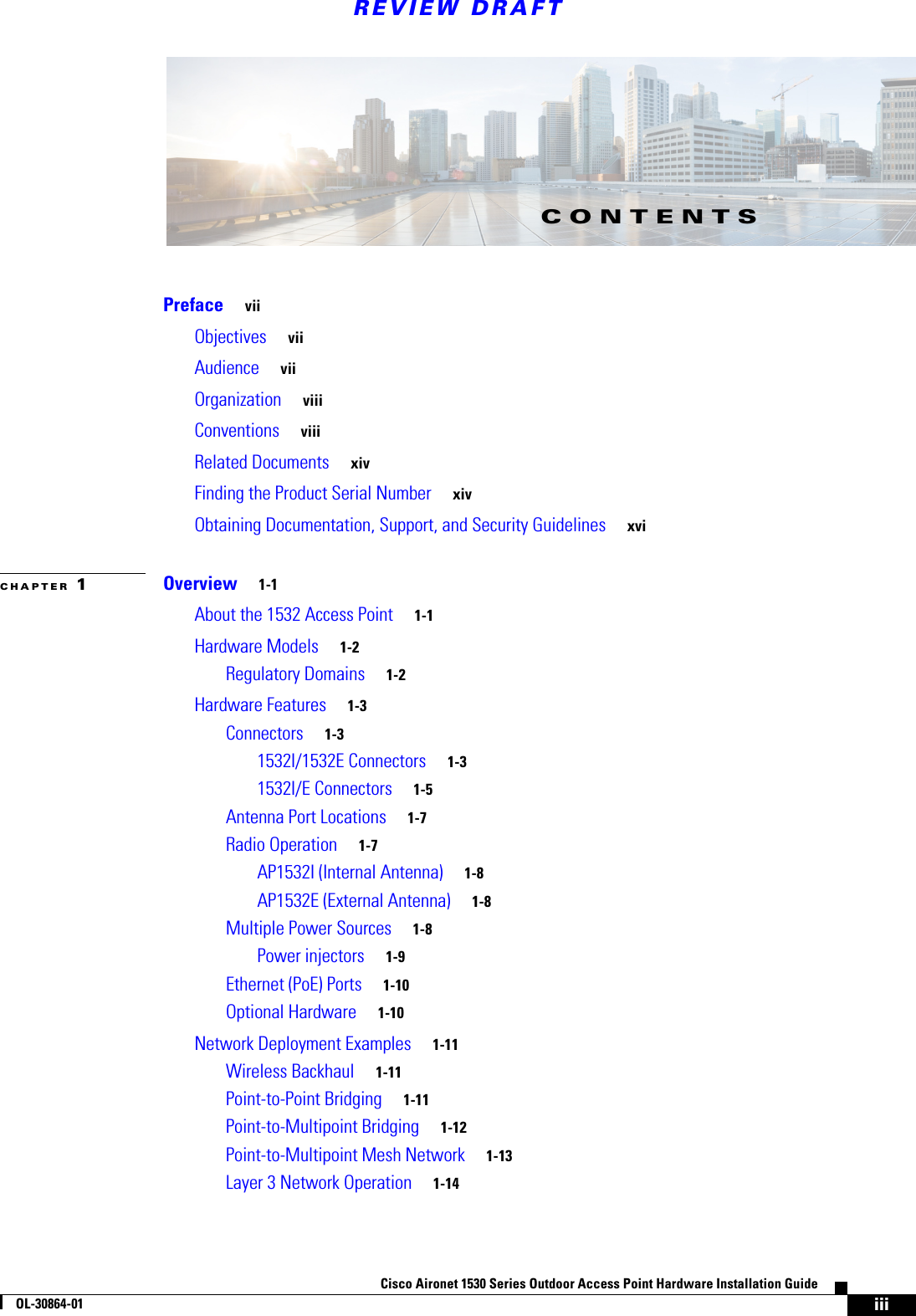
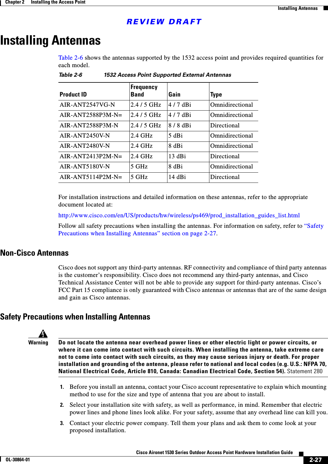
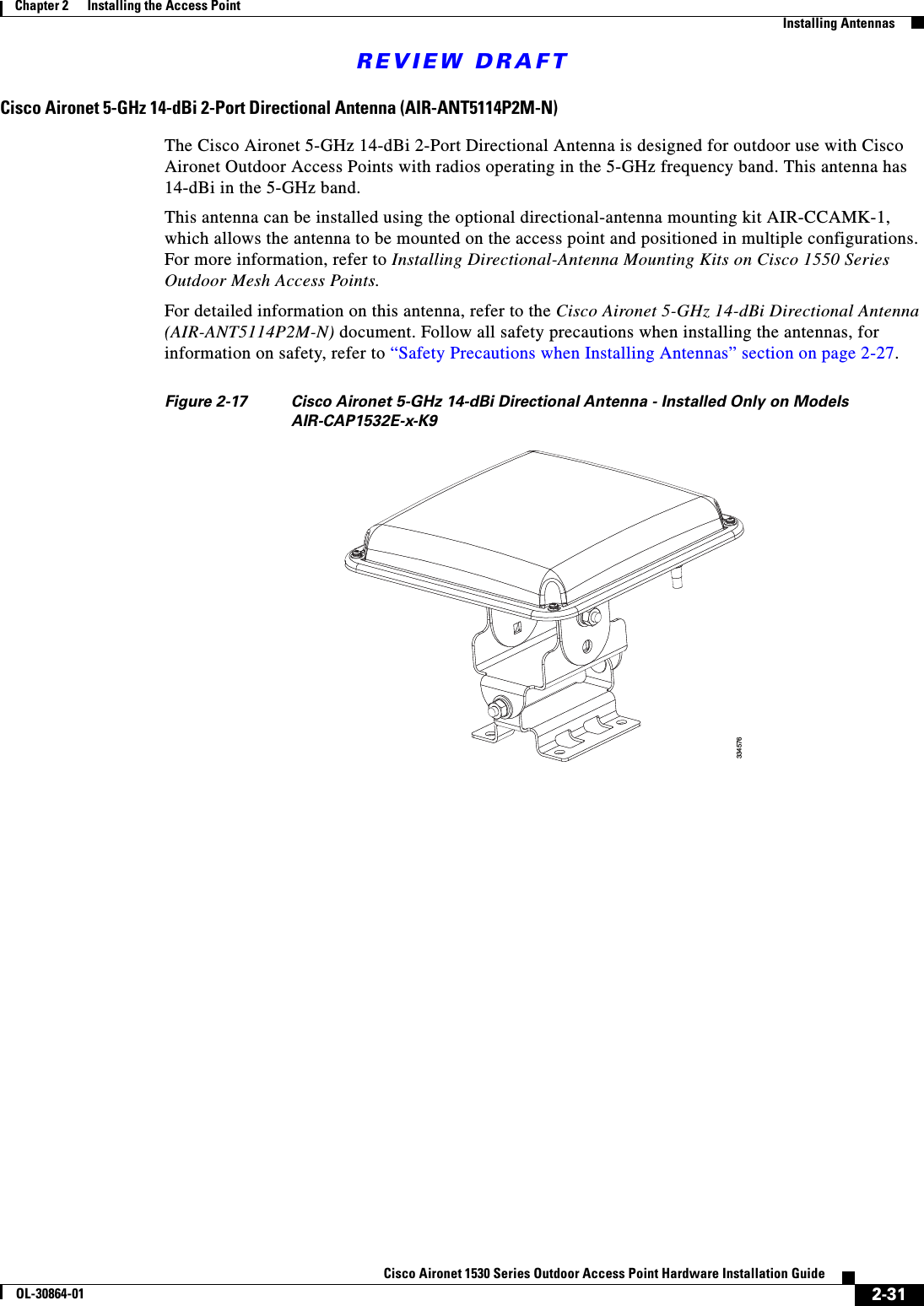
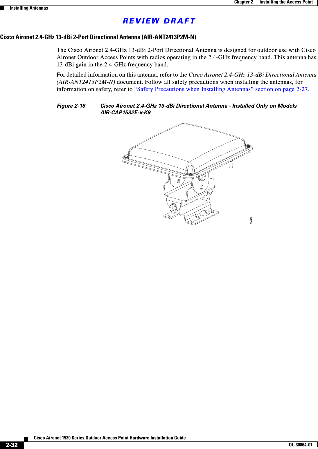
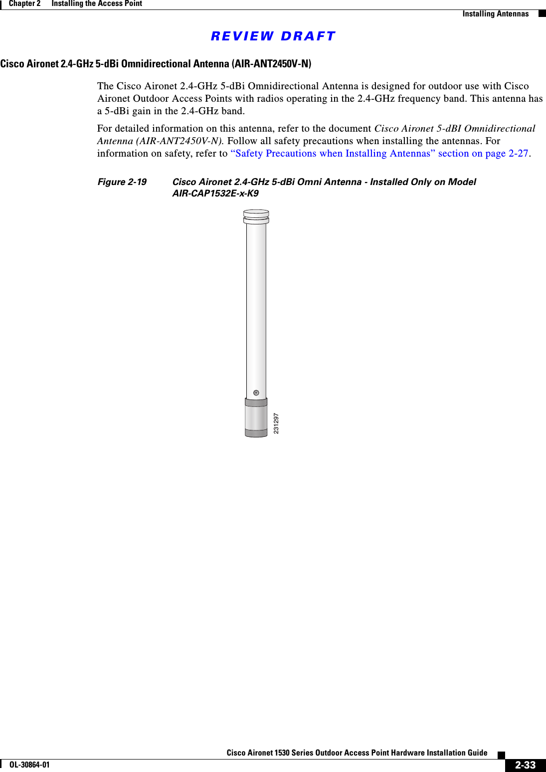
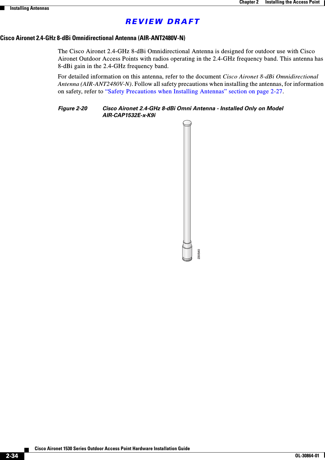
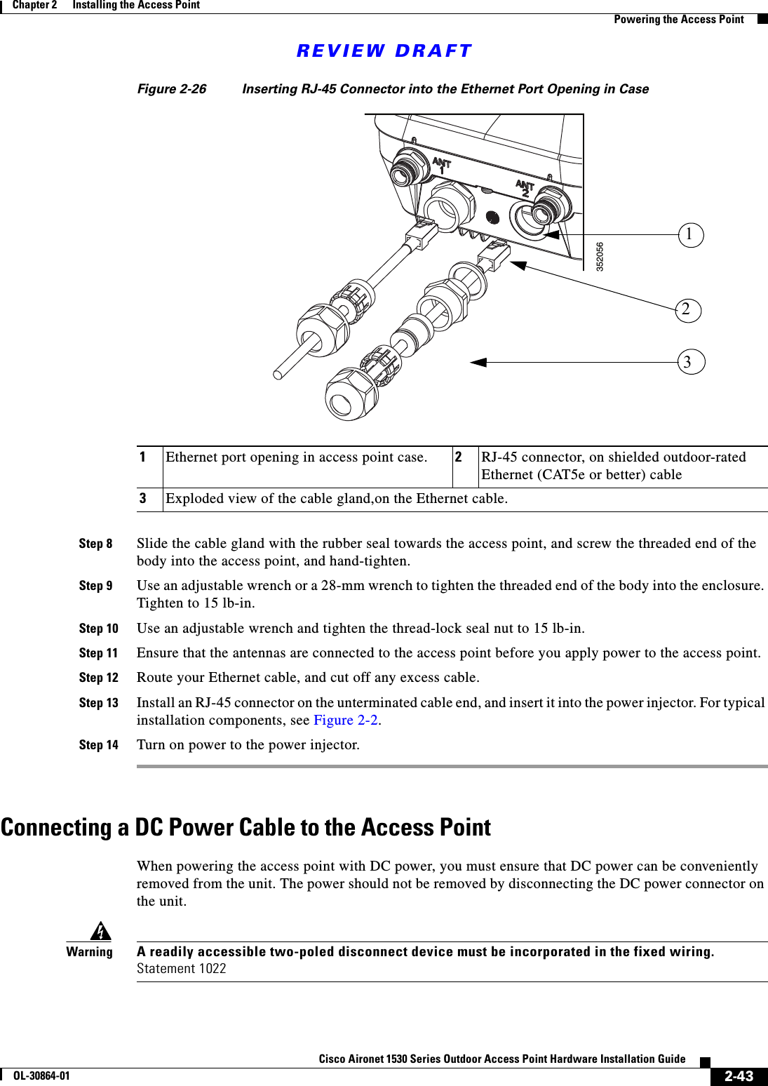
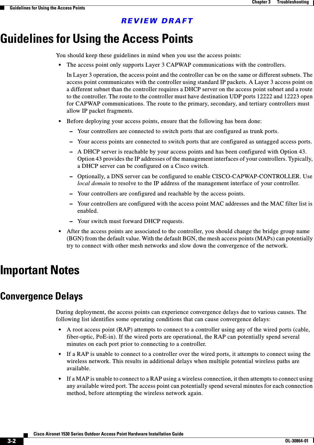
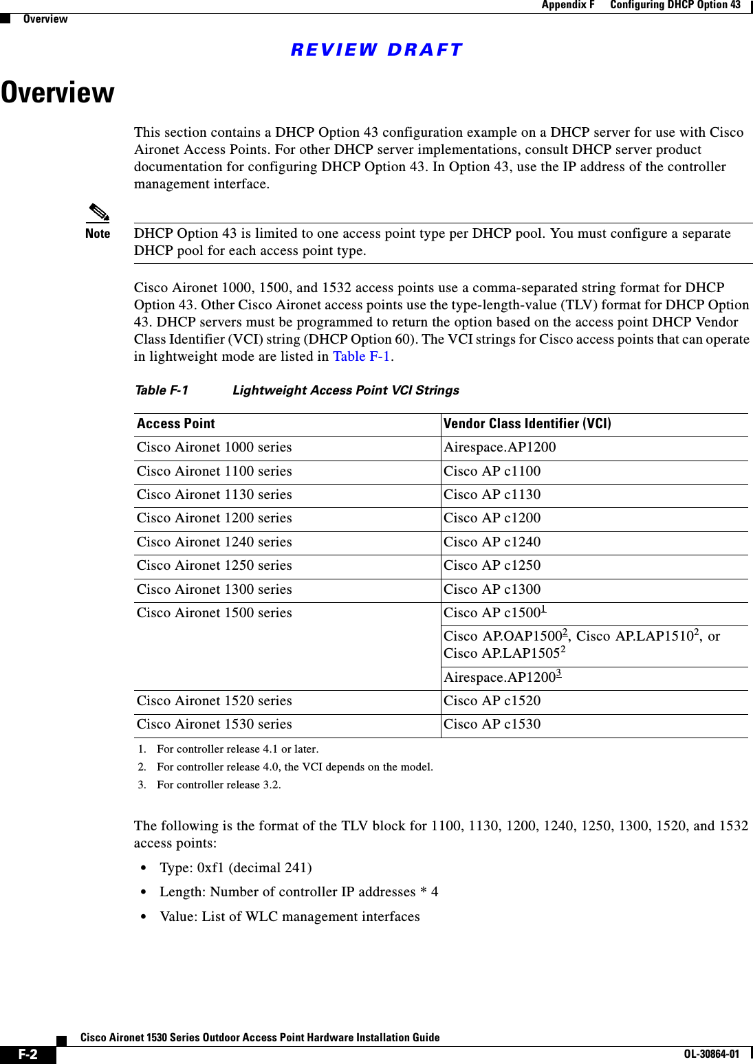
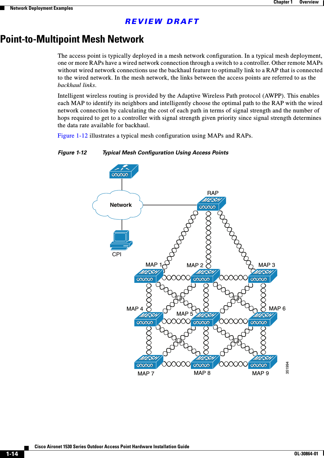
![REVIEW DRAFTviiiCisco Aironet 1530 Series Outdoor Access Point Hardware Installation GuideOL-30864-01OrganizationThis guide contains the following sections:ConventionsThis publication uses the following conventions:Chapter Title DescriptionChapter 1 Overview Describes the major components and features of the access point.Chapter 2 Installing the Access Point Provides warnings, safety information, and mounting information you need to install your access point.Chapter 3 Troubleshooting Provides basic troubleshooting procedures for the access point. Appendix A Translated Safety Warnings Indicates how to access the document that provides translations of the safety warnings that appear in this publication.Appendix B Declarations of Conformity and Regulatory InformationDescribes the regulatory conventions to which the access point conforms and provides guidelines for operating access points in Japan.Appendix C Channels and Power Levels Indicates how to access the document that lists the access point radio channels and the maximum power levels supported by the world regulatory domains.Appendix D Access Point Data Sheet Lists technical specifications for the access point.Appendix E Access Point Pinouts Describes the connector pinouts for the access point.Appendix F Configuring DHCP Option 43Describes the procedure to configure DHCP Option 43.Convention Descriptionboldface font Commands, command options, and keywords are in boldface.italic font Arguments for which you supply values are in italics.[ ] Elements in square brackets are optional.screen font Terminal sessions and information the system displays are in screen font.boldface screen font Information you must enter is in boldface screen font.italic screen font Arguments for which you supply values are in italic screen font.](https://usermanual.wiki/Cisco-Systems/102089P.Manual/User-Guide-2129485-Page-8.png)
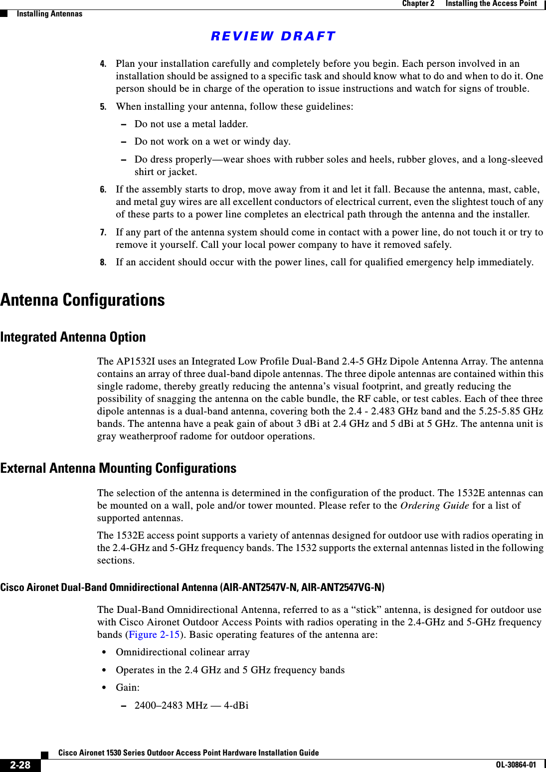
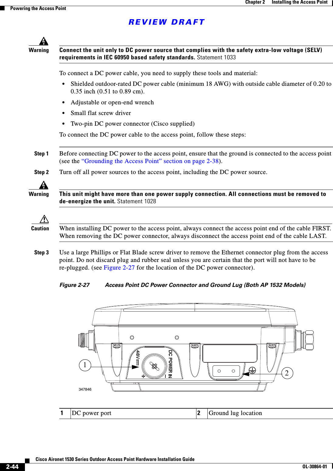
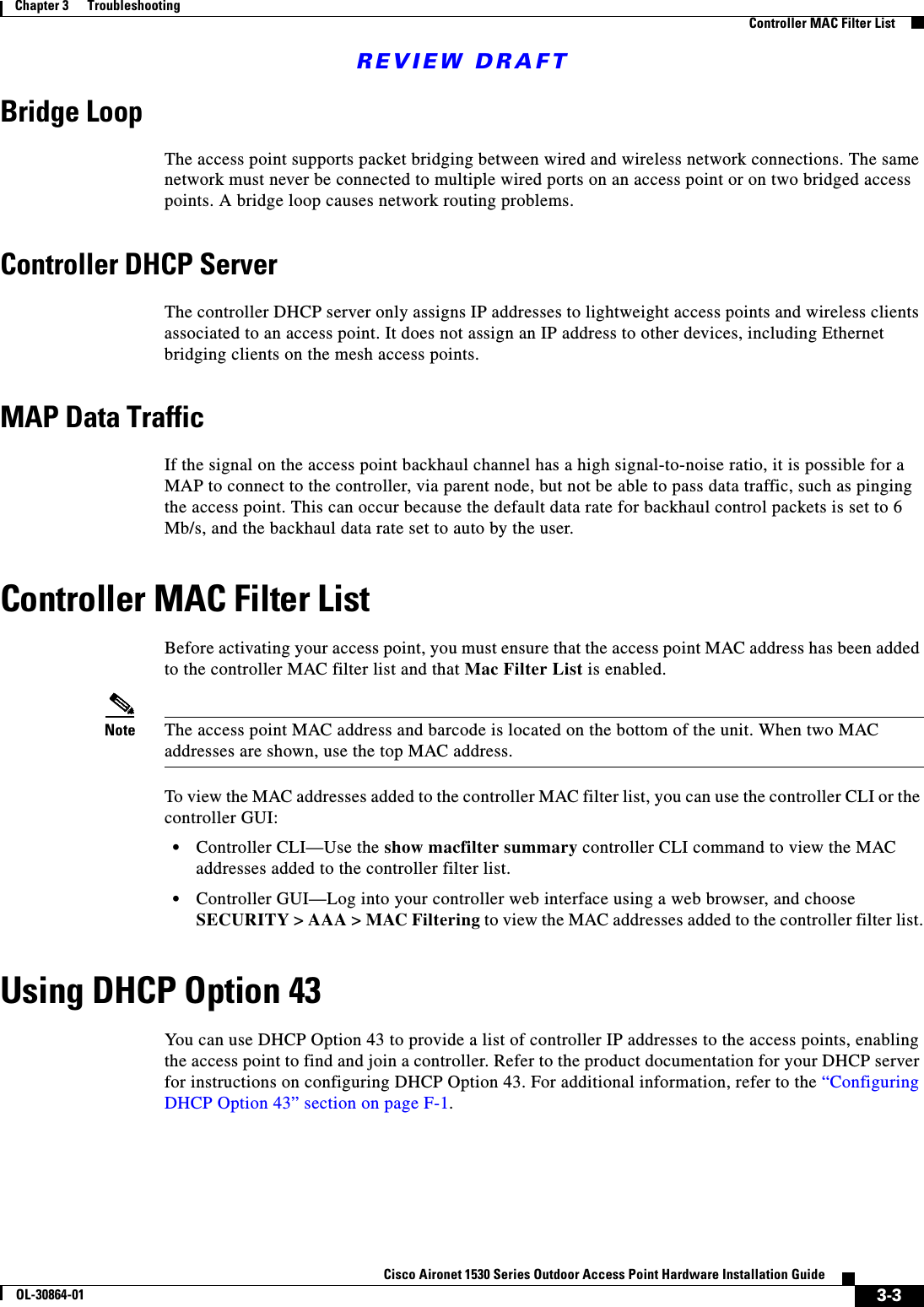
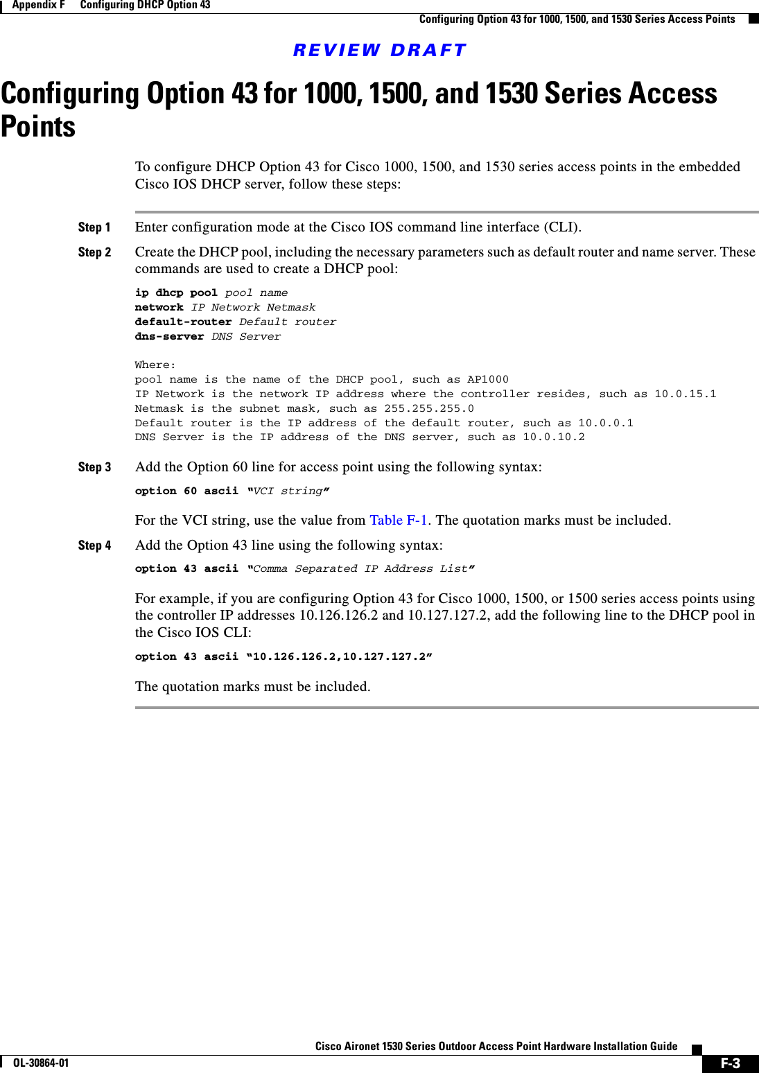
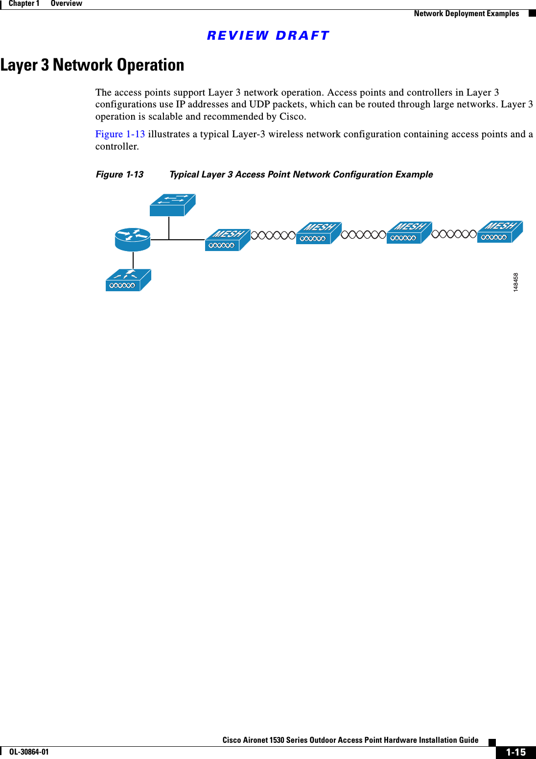
![REVIEW DRAFT1-10Cisco Aironet 1530 Series Outdoor Access Point Hardware Installation GuideOL-30864-01Chapter 1 OverviewHardware FeaturesEthernet (PoE) PortsThe access point supports an Ethernet uplink port (PoE-In). The access point Ethernet uplink port uses an RJ-45 connector (with weatherproofing) to link the access point to the 10BASE-T, 100BASE-T or 1000BASE-T network. The Ethernet cable is used to send and receive Ethernet data and to optionally supply inline power from the power injector or a suitably powered switch port.Tip The access point senses the Ethernet and power signals and automatically switches internal circuitry to match the cable connections.WarningTo reduce the risk of fire, use only No. 26 AWG or larger telecommunication line cord. Statement 1023The Ethernet cable must be a shielded outdoor rated Category 5e (CAT5e) or better cable. The access point senses the Ethernet and power signals and automatically switches internal circuitry to match the cable connections.Optional HardwareDepending on what you ordered, the following optional access point hardware may be part of your shipment:•External antennas, depending on which ones you purchased (See “AP1532E (External Antenna)” section on page 1-8 for information on available external antennas.)•Wall/Pole mount bracket (AIR-ACCPMK1530-PMK1 [=])•Wall/Pole mount bracket with tilt mechanism, spare only (AIR-ACC1530-PMK2=)•Street light power tap (AIR-PWR-ST-LT-R3P=), works only with the AC/DC power adapter.•Power injector (AIR-PWRINJ1500-2=, AIR-PWRINJ4=)•AP cover / Solar Shield for 1532, spare only (AIR-ACC1530-CVR=)•AC/DC power adapter, spare only (AIR-PWRADPT-1530=)•Spare Parts kit containing extra cable glands, power connector, ground lug, etc. (AIR-ACC1530-KIT1=)](https://usermanual.wiki/Cisco-Systems/102089P.Manual/User-Guide-2129485-Page-26.png)

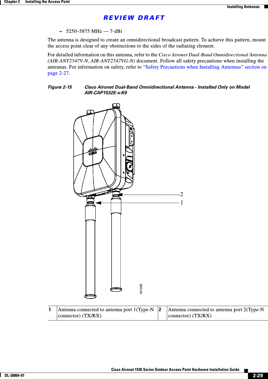
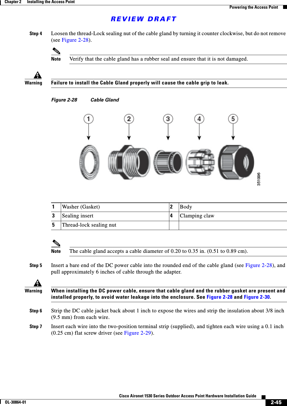
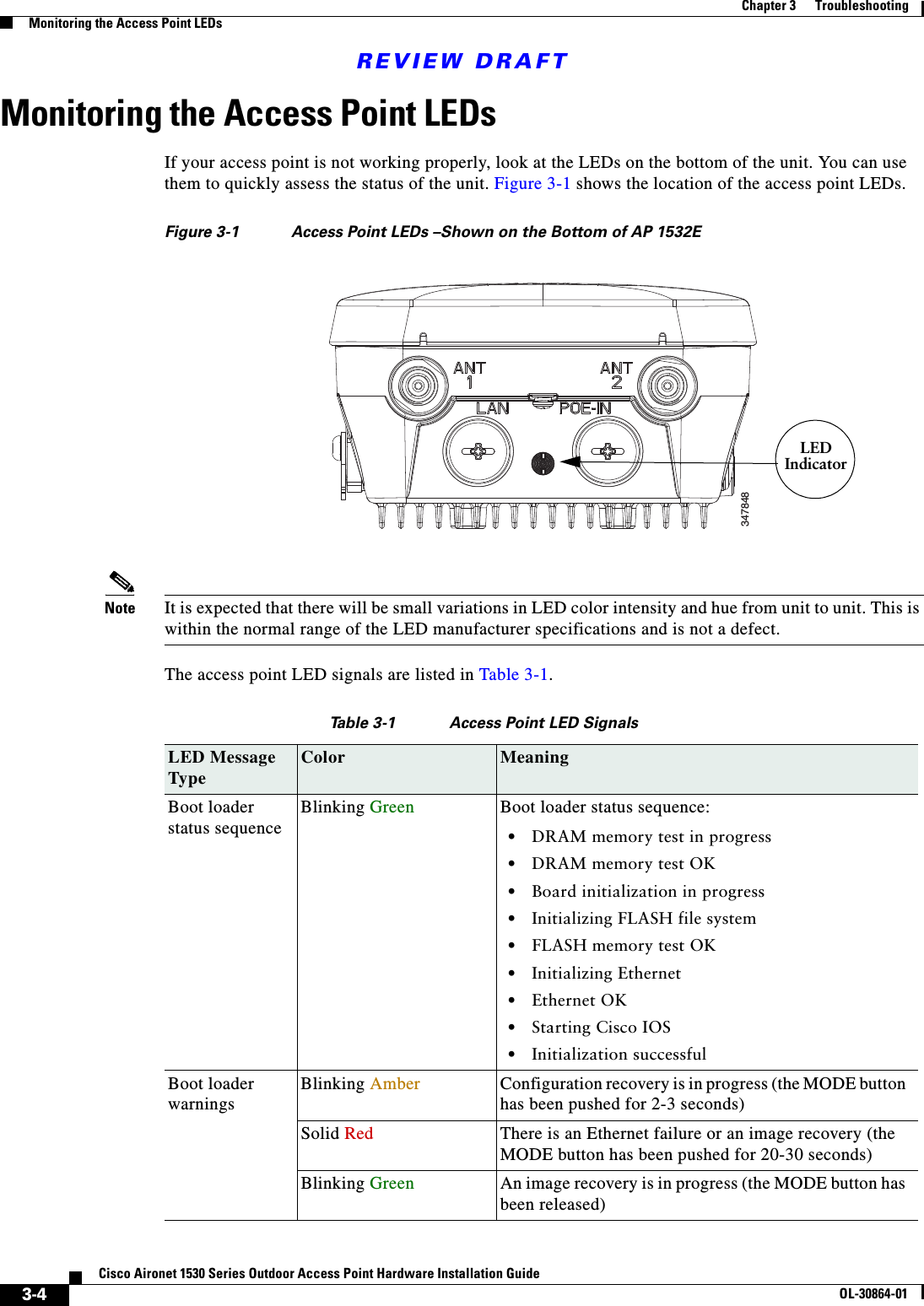
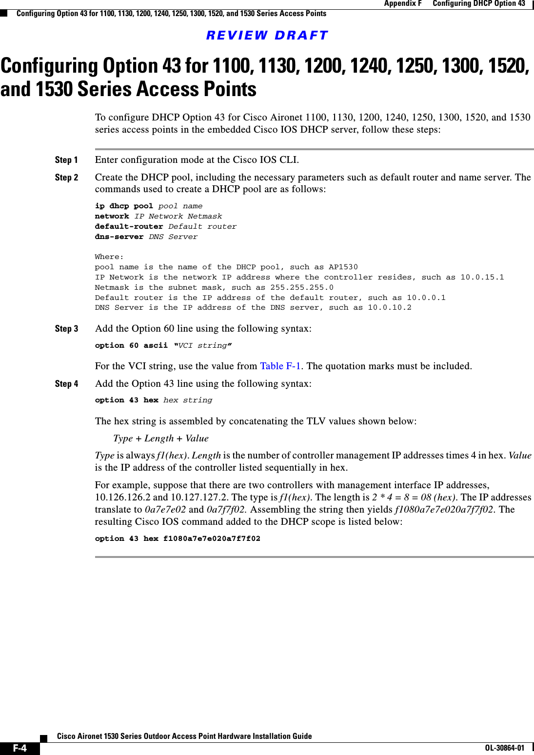
![REVIEW DRAFT2-2Cisco Aironet 1530 Series Outdoor Access Point Hardware Installation GuideOL-30864-01Chapter 2 Installing the Access PointUnpacking the Access PointUnpacking the Access PointTo unpack the access point, follow these steps:Step 1 Open the shipping container and carefully remove the contents. Step 2 Return all packing materials to the shipping container, and save it.Step 3 Ensure that all items listed in “Package Contents” are included in the shipment. If any item is damaged or missing, notify your authorized Cisco sales representative. Package ContentsEach access point package contains the following items:•One 1530 series access point•Two-pin DC power connector•Ground lug and screws with lock washers•Plastic cable gland and rubber seal•Weatherization tape and anti-corrosion sealant•Cisco product documentation and pointer cardTools and HardwareThe tools and hardware used to install the 1532 access point are described in:•Optional Tools and Hardware, page 2-2•Optional Tools and Hardware That You Supply, page 2-3•Warnings, page 2-3•Warnings, page 2-3Optional Tools and HardwareDepending on what you ordered, the following optional equipment may be part of your shipment:•External antennas, depending on which ones you purchased (see “Antenna Configurations” section on page 2-28 for more information).•Wall/Pole mount bracket, available as an option or a spare (AIR-ACC1530-PMK1[=])•Wall/Pole mount bracket with tilt mechanism, spare only (AIR-ACC1530-PMK2=)•AP cover / Solar Shield for 1532, spare only (AIR-ACC1530-CVR=)•AC/DC power adapter, spare only (AIR-PWRADPT-1530=)•Spare Parts kit containing extra cable glands, power connector, ground lug, etc. (AIR-ACC1530-KIT1=)](https://usermanual.wiki/Cisco-Systems/102089P.Manual/User-Guide-2129485-Page-34.png)
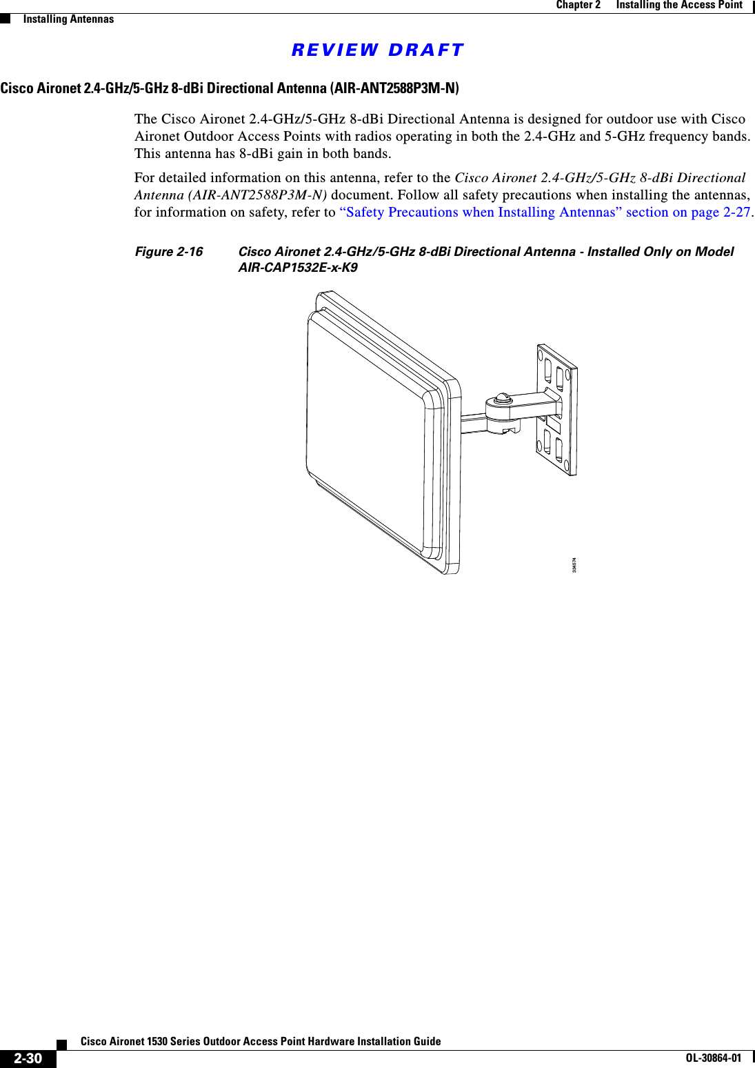
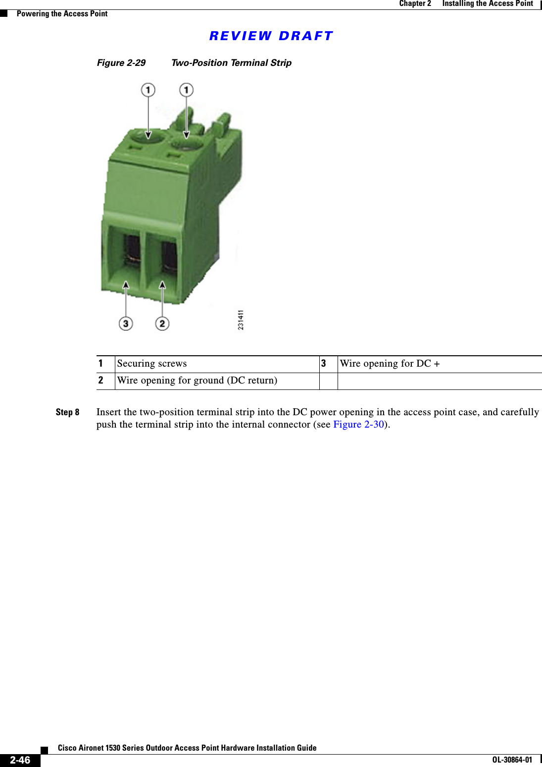
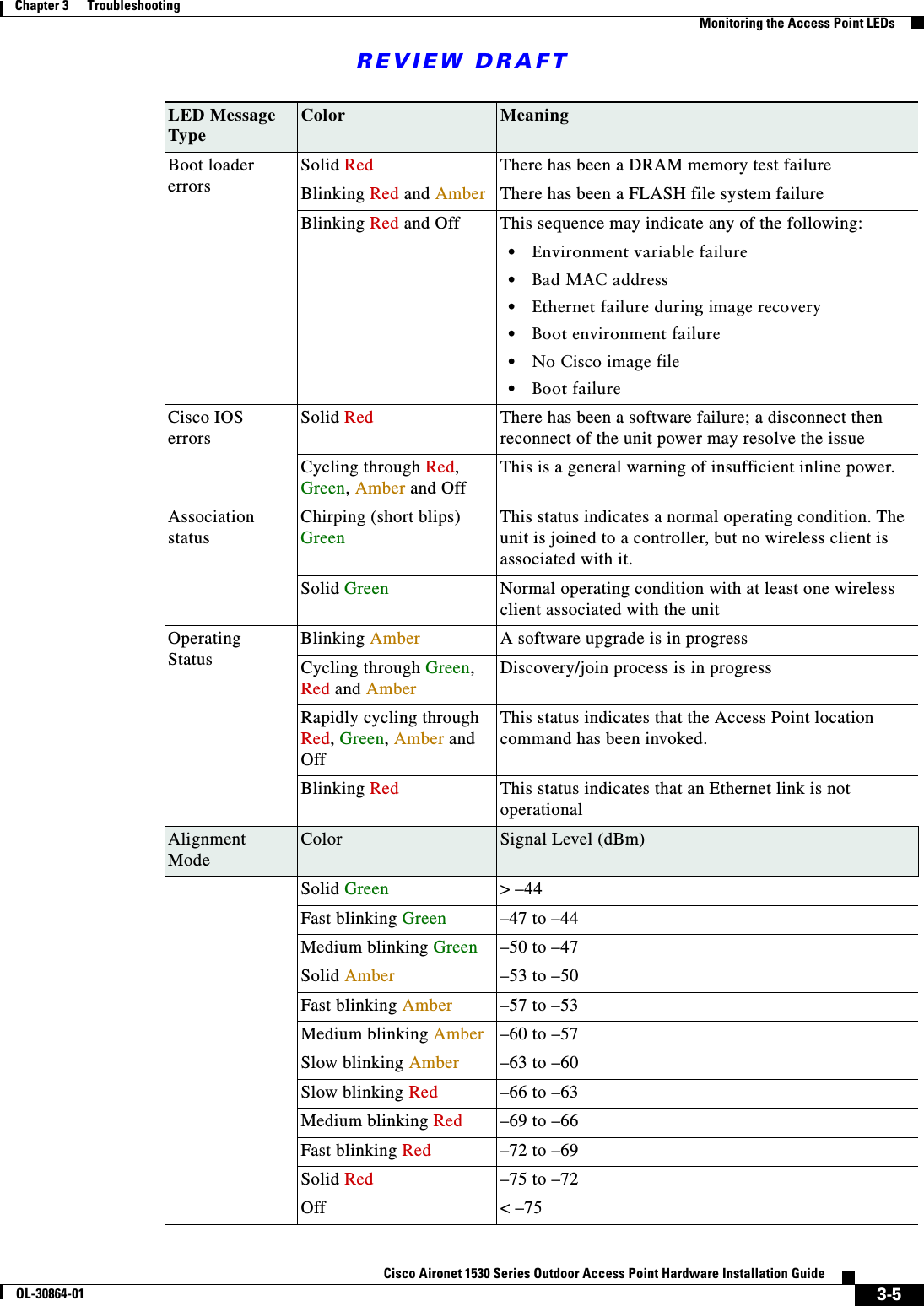
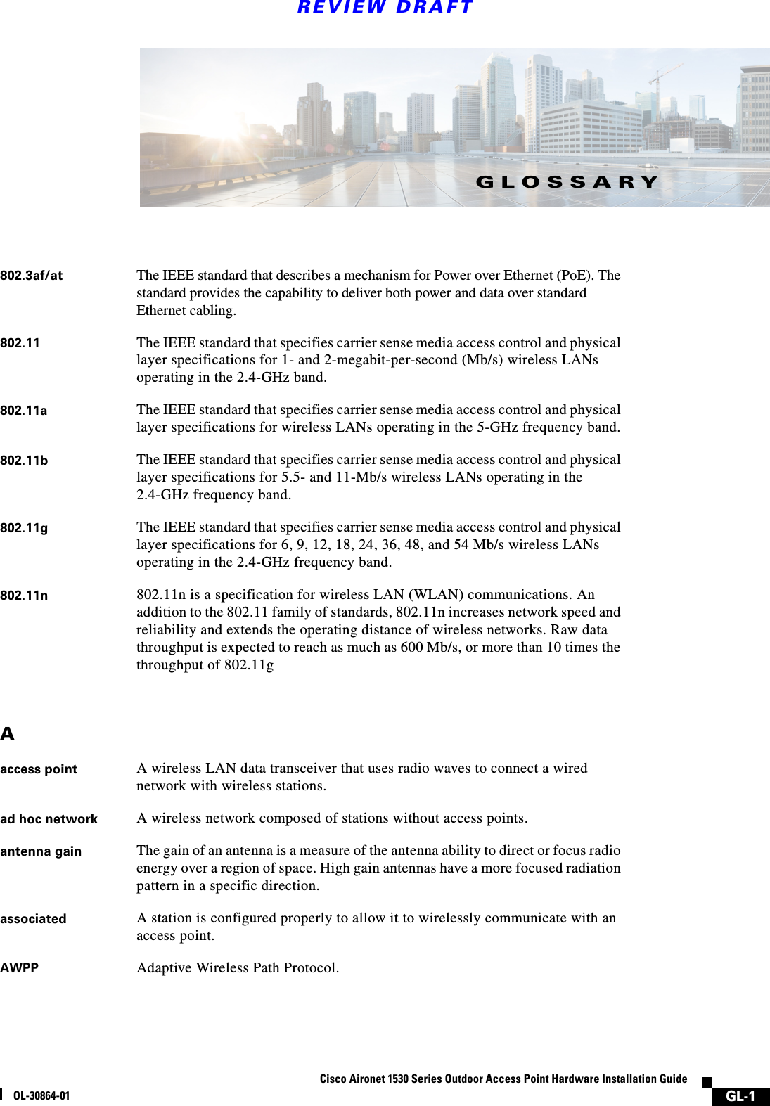
![REVIEW DRAFT2-6Cisco Aironet 1530 Series Outdoor Access Point Hardware Installation GuideOL-30864-01Chapter 2 Installing the Access PointAvoiding Damage to Radios in a Testing Environment•If any part of the antenna system should come in contact with a power line, do not touch it or try to remove it yourself. Call your local power company. They will remove it safely. If an accident should occur, call for qualified emergency help immediately.Avoiding Damage to Radios in a Testing EnvironmentThe radios on outdoor units (bridges) have higher transmit power levels than radios on indoor units (access points). When you test high-power radios in a link, you must avoid exceeding the maximum receive input level for the receiver. At levels above the normal operating range, packet error rate (PER) performance is degraded. At even higher levels, the receiver can be permanently damaged. To avoid receiver damage and PER degradation, you can use one of the following techniques:•Separate the omnidirectional antennas by at least 2 ft (0.6 m) to avoid receiver damage or by at least 25 ft (7.6 m) to avoid PER degradation.Note These distances assume free space path loss and are conservative estimates. Required separation distances for damage and performance degradation levels in actual deployments are less if conditions are not non-line-of-sight.•Reduce the configured transmit power to the minimum level.•Use directional antennas, and keep them away from each other.•Cable the radios together using a combination of attenuators, combiners, or splitters to achieve a total attenuation of at least 60 dB.For a radiated test bed, the following equation describes the relationships among transmit power, antenna gain, attenuation, and receiver sensitivity:txpwr + tx gain + rx gain - [attenuation due to antenna spacing] < max rx input levelWhere:txpwr = Radio transmit power leveltx gain = transmitter antenna gainrx gain = receiver antenna gainFor a conducted test bed, the following equation describes the relationships among transmit power, antenna gain, and receiver sensitivity:txpwr - [attenuation due to coaxial components] < max rx input levelCaution Under no circumstances should you connect the antenna port from one access point to the antenna port of another access point without using an RF attenuator. If you connect antenna ports, you must not exceed the maximum survivable receive level of 0 dBm. Never exceed 0 dBm, or damage to the access point can occur. Using attenuators, combiners, and splitters having a total of at least 60 dB of attenuation ensures that the receiver is not damaged and that PER performance is not degraded.Installation GuidelinesBecause the access point is a radio device, it is susceptible to common causes of interference that can reduce throughput and range. Follow these basic guidelines to ensure the best possible performance:•For information on planning and initially configuring your Cisco Mesh network, refer to the Cisco Wireless Access Points, Design and Deployment Guide, Release 7.3.](https://usermanual.wiki/Cisco-Systems/102089P.Manual/User-Guide-2129485-Page-38.png)