Cisco Systems 102089P Cisco Aironet 1530 Series Outdoor Access Point User Manual ap1532qsg
Cisco Systems Inc Cisco Aironet 1530 Series Outdoor Access Point ap1532qsg
UserManual.wiki
>
Cisco Systems
>
102089P User Manual
>
Updated User Manual
Contents
1.
Manual
2.
Updated User Manual
Updated User Manual
Navigation menu
Upload a User Manual
Namespaces
Wiki Guide
HTML
PDF
Info
Views
User Manual
Discussion / Help
Navigation
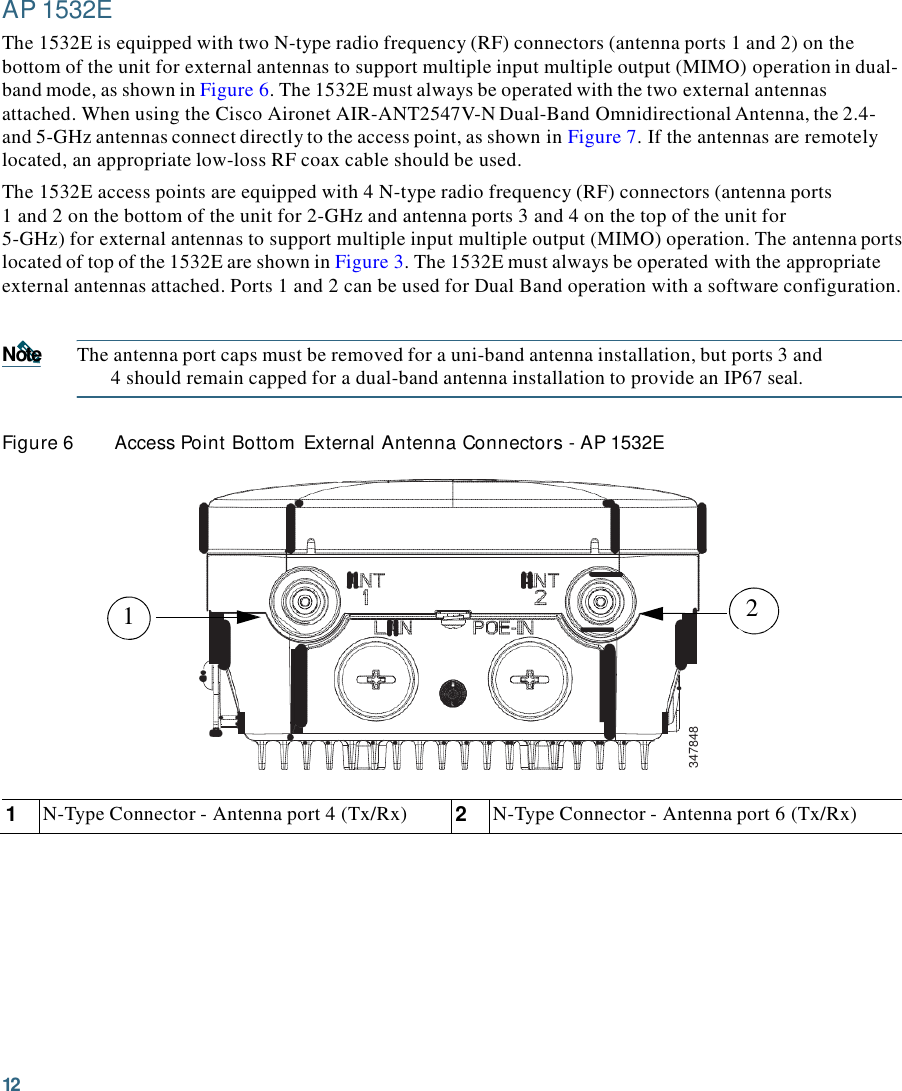
![5 3 Unpacking the Access Point Follow these steps to unpack the access point: Step 1 Open the shipping container and carefully remove the contents. Step 2 Return all packing materials to the shipping container and save it. Step 3 Ensure that all items listed in the “Package Contents” section on page 5 are included in the shipment. Check each item for damage. If any item is damaged or missing, notify your authorized Cisco sales representative. Package Contents Each access point package contains the following items: • One 1530 series access point • Two-pin DC power connector • Ground lug (Panduit PLCD6-10A-L) and screws with lock washers • Plastic cable gland and rubber seal • Weatherization tape and anti-corrosion sealant • Cisco product documentation and translated safety warnings Optional Equipment Depending on what you ordered, the following optional equipment may be part of your shipment: • External antennas, depending on which ones you purchased (see “1532E Antennas” section on page 6 for more information). • Wall/Pole mount bracket, available as an option or a spare (AIR-ACC1530-PMK1[=]) • Wall/Pole mount bracket with tilt mechanism, spare only (AIR-ACC1530-PMK2=) • AP cover / Solar Shield for 1532, spare only (AIR-ACC1530-CVR=) • AC/DC power adapter, spare only (AIR-PWRADPT-1530=) • Spare Parts kit containing extra cable glands, power connector, ground lug, etc. (AIR-ACC1530-KIT1=)](https://usermanual.wiki/Cisco-Systems/102089P.Updated-User-Manual/User-Guide-2167703-Page-5.png)
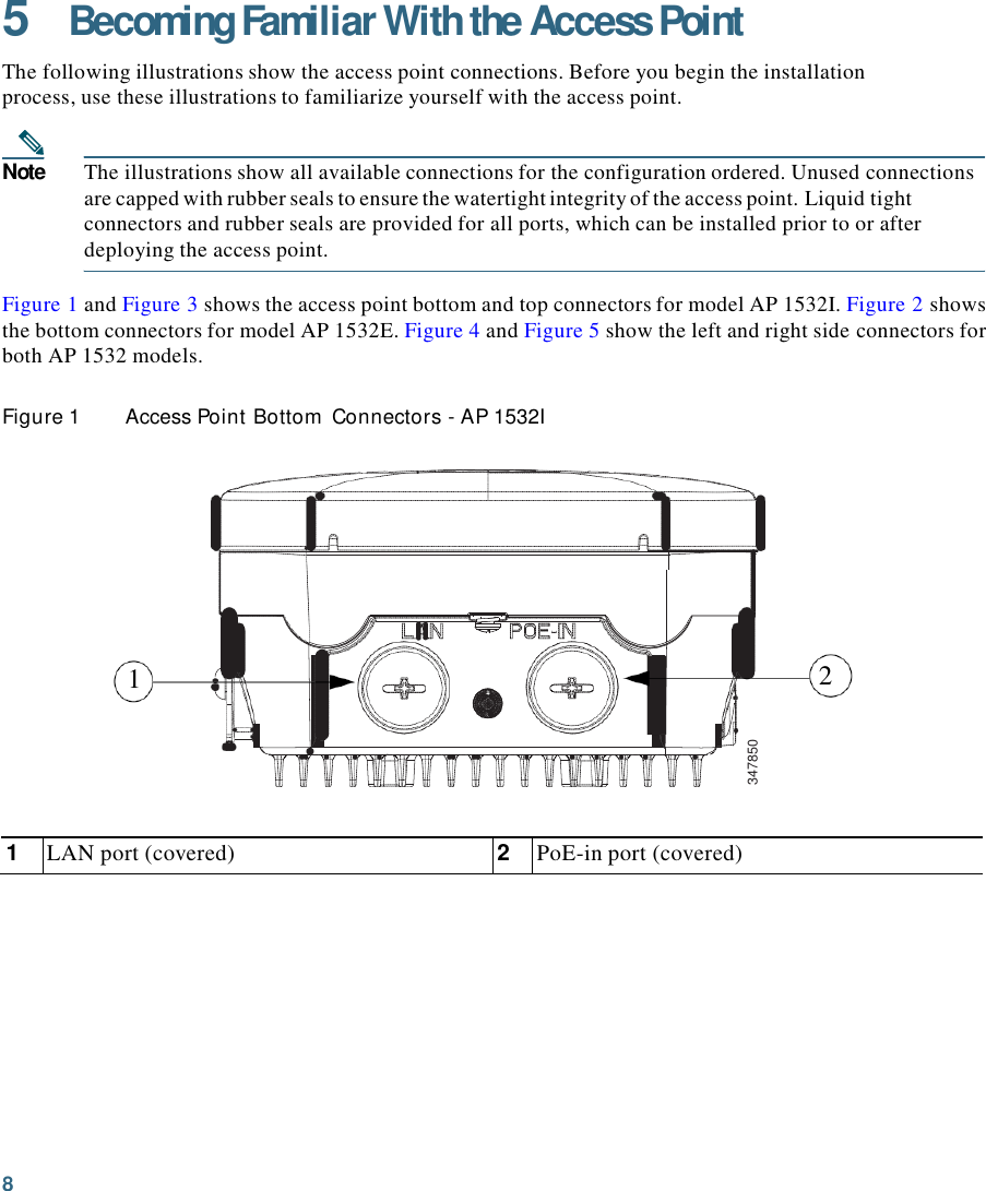
![25 For a radiated test bed, the following equation describes the relationships among transmit power, antenna gain, attenuation, and receiver sensitivity: txpwr + tx antenna gain + rx ant gain - [attenuation due to antenna spacing] < max rx input level Where: txpwr = Radio transmit power level tx gain = transmitter antenna gain rx gain = receiver antenna gain For a conducted test bed, the following equation describes the relationships among transmit power, antenna gain, and receiver sensitivity: txpwr - [attenuation due to coaxial RF Attenuator components] < max rx input level (0 dbm) Caution Under no circumstances should you connect the antenna port from one access point to the antenna port of another access point without using an RF attenuator. If you connect antenna ports you must not exceed the maximum survivable receive level of 0 dBm. Never exceed 0 dBm or damage to the access point can occur. Using attenuators, combiners, and splitters having a total of at least 60 dB of attenuation ensures that the receiver is not damaged and PER performance is not degraded. Before You Begin Warning Read the installation instructions before connecting the system to the power source. Statement 1004 Before you begin the installation process: • Become familiar with the procedures for mounting the access point (see the AP Pole/Wall Mount, page 17). • Become familiar with the access point connections (Figure 1 on page 8, Figure 4 on page 10, and Figure 5 on page 10). • Verify that the switch you are using to connect the controller is configured properly.](https://usermanual.wiki/Cisco-Systems/102089P.Updated-User-Manual/User-Guide-2167703-Page-25.png)
![30 Autonomous Mode Configuration The 1530 Series allows the Unified (controller-based) and Autonomous mode software to be loaded at the factory on the same hardware part number. This eliminates the need for separate part numbers for controller-based units and autonomous mode units. At boot-up, the default mode is controller-based. The 1530 will power up and begin searching for a controller. Once it joins the controller, it will download the active Unified image from the controller. This is the same operation as other Cisco controller-based APs. For Autonomous mode, the user should take the following steps: Step 1 Power the AP and connect to the console. Step 2 From the Command Line, enter: AP # capwap ap autonomous (# means privileged EXEC mode) Step 3 The system will respond with "Convert to Autonomous image. Proceed? (yes/[No]):" Step 4 Type "yes" to confirm. Step 5 The AP will then re-boot and load the Autonomous image. The unified image is erased. Step 6 Once the 1530 has booted in autonomous mode, configuration of the AP can done by following the procedure outlined here: http://www.cisco.com/en/US/partner/docs/wireless/access_point/12.4_10b_JA/configuration/guid e/scg12410b.html](https://usermanual.wiki/Cisco-Systems/102089P.Updated-User-Manual/User-Guide-2167703-Page-30.png)
![44 Declaration of Conformity with regard to the R&TTE Directive 199915/EC & Medical Directive 93/42/EEC 6bJlrapCKH [Bul garian] Tosa o6opy11saue OTrosapll ua CbuteCTBemne lf3HCKB31Hill H nplinOlKHMH KJJayJn ua }lHpeKTlisa 1999/5/EC. Cesky [Czech]: Toto 7,.afizeni jc v souladu se 7.a kladn imi po'.adavky a ostatnimi odpovidajicirni ustanovcnimi Sm¢m icc 1999/5/EC. Dansk [Danish]: Dette udstyr er i overensstemmelse med de V<£sentlige krav og andre relevante besternmelser i Direktiv 1999/5/EF. Deutsc h [German): Dieses Gerlit entspricht den grundlegenden Anfordenmgen und den weiteren entsprechenden Vorgaben der Richtlinie 1999/5/EU. Eesti [Estonian]: See seade vastab direktiivi 1999/5/EO olulistele noueteleja teistele asjakohastele s.iitetele. English: This eq uipment is in compliance with the essential requirements and ot her relevant provisions of Directive 1999/5/EC. Espa11ol [Spanish]: Este equipo cumple con los requisites esenciales asi como con ot ras disposiciones de Ia Direct iva 1999/5/CE. EMTJVI"il [Greek): Aur6 0 cl;on),\Oll £1\rQI cr£ OUl16piP<l)<ITJ £ n 0\J<HWOEHQ; nQitl]0'£1KQI aJ O'XE"riKt oJara £n1Oo•rria1 999/5/EC. Fra n ais [French]: Cet apparei l est confonne aux exigences essentielles et aux autres dispositions pertinentes de Ia Direct ive 1 999/5/EC. islenska [Icelandic): Italiano [Italian]: !>etta ta::ki cr samkva::m t grunnkrOfum og Mntm viociga ndi a kva:oum Ti lskipuna r 1999/5/EC. Questo apparato e confonne ai req uisiti essenzial i ed agli altri principi sanciti dalla Direttiva 1999/5/CE. Latvieu [Latvian]: Si iekllrta atbilst. OirektTvas 1 999/5/EK biit iskajllm prasTbllm un citiem ar to saistilajiem noteikum icm.](https://usermanual.wiki/Cisco-Systems/102089P.Updated-User-Manual/User-Guide-2167703-Page-44.png)