Cisco Systems 102089P Cisco Aironet 1530 Series Outdoor Access Point User Manual ap1532qsg
Cisco Systems Inc Cisco Aironet 1530 Series Outdoor Access Point ap1532qsg
Contents
- 1. Manual
- 2. Updated User Manual
Updated User Manual

GETTING STARTED
G
UIDE
Cisco Aironet 1530 Series Outdoor Mesh Access Points
INCLUDING LICENSE AND WARRANTY
Revised October 11, 2013
1 About this Guide
2 Introduction to the Access Point
3 Unpacking the Access Point
4 Radio Configuration
5 Becom ing Fam iliar With the Access Point
6 AP Pole/Wall M ount
7 Preparing the Access Point
8 Deploying the Access Point
9 In Case of Difficulty
10 Declarations of Conformity and Regulatory Information
11 Warranty

2
1 About this Guide
This guide is designed to familiarize you with your Cisco Aironet 1530 Series Outdoor Mesh Access Point
and prepare it for use in your wireless network. For in-depth details on configuring a wireless mesh
network, please see:
• Cisco Mesh Networking Solution Deployment Guide
Detailed configuration information can also be found in the Cisco wireless LAN controller documentation
for the controller and software release you are using. These documents are available on Cisco.com. Follow
these steps to access these documents:
Step 1 Browse to http://www.cisco.com.
Step 2 Click Support. A pop-up window appears.
Step 3 Click Wireless under Select a Product Name. The Select Your Product or Technology page
appears.
Step 4 Click Wireless > Outdoor Wireless.
Step 5 Click Cisco AP 1530 Series in the Search for a Specific Product field. The Cisco 1530 Series
Introduction page
appears.
Step 6 Choose the appropriate link for the documentation you want to view or download.
General Safety Guidelines
Warnings
Safety warnings appear throughout this guide in procedures that may harm you if performed incorrectly. A
warning symbol precedes each warning statement. The warnings below are general warnings that are
applicable to the entire guide. Specific warnings are included in the sections to which they apply.
Warning This warning symbol means danger. You are in a situation that could cause bodily
injury.
Before you work on any equipment, be aware of the hazards involved with
electrical
circuitry and be familiar with standard practices for preventing accidents. Use
the
statement number provided at the end of each warning to locate its translation in
the
translated safety warnings that
accompanied
this device.
Statement 1071
SAVE THESE
INSTRUCTIONS

3
Warning Do not operate the unit near unshielded blasting caps or in an explosive
environment
unless the device has been modified to be especially qualified for
such use.
Statement
364
Warning This equipment must be externally grounded using a
customer-supplied
ground
wire
before power is applied. Contact the appropriate electrical inspection authority or
an
electrician if you are uncertain that suitable grounding is available.
Statement
366
Warning Read the installation instructions before connecting the system to the power
source.
Statement
1004
Warning Only trained and qualified personnel should be allowed to install, replace, or
service
this equipment. Statement
1030
Warning Ultimate disposal of this product should be handled according to all national laws
and
regulations. Statement
1040
4
2 Introduction to the Access Point
The Cisco Aironet 1530 Series Outdoor Mesh Access Point (hereafter called the access point or AP) is a
rugged outdoor access point designed for service in mesh networks. The 1530 series leverages
802.11n technology with integrated radio and internal/external antennas.
The 1530 contains a 2.4-GHz and 5-GHz radio with an option to configure in centralized, Flexconnect, or
mesh mode. The 2.4-GHz radios are used primarily for local access, and the 5-GHz radios can be
configured for both local access and/or wireless backhaul in the Mesh mode.
The access point is a standalone unit that can be wall, pole or tower mounted. The access point can also
operate as a relay node for other access points not directly connected to a wired network. Intelligent wireless
routing is provided by the Adaptive Wireless Path Protocol (AWPP). This enables each access point to
identify its neighbors and intelligently choose the optimal path to the wired network by calculating the cost
of each path in terms of signal strength and the number of hops required to get to a controller. The access point
is configured, monitored, and operated through a Cisco wireless LAN controller (WLC), referred to as a
controller in this document. The WLC is described in the appropriate Cisco Wireless LAN Controller
Configuration Guide. The Cisco Mesh Networking Solution Deployment Guide describes how to plan and
initially configure the Cisco mesh network, which supports wireless
point-to-point
and
point-to-multipoint
mesh deployments. The controllers use a browser-based management system, a command-line interface
(CLI), or the Cisco Prime Infrastructure (CIP) network management system to manage the controller and the
associated access points.

5
3 Unpacking the Access Point
Follow these steps to unpack the access point:
Step 1 Open the shipping container and carefully remove the contents.
Step 2 Return all packing materials to the shipping container and save it.
Step 3 Ensure that all items listed in the “Package Contents” section on page 5 are included in the
shipment. Check each item for damage. If any item is damaged or missing, notify your authorized
Cisco sales representative.
Package Contents
Each access point package contains the following items:
• One 1530 series access point
• Two-pin DC power connector
• Ground lug (Panduit PLCD6-10A-L) and screws with lock washers
• Plastic cable gland and rubber seal
• Weatherization tape and anti-corrosion sealant
• Cisco product documentation and translated safety warnings
Optional Equipment
Depending on what you ordered, the following optional equipment may be part of your shipment:
• External antennas, depending on which ones you purchased (see “1532E Antennas” section on page 6
for more information).
• Wall/Pole mount bracket, available as an option or a spare (AIR-ACC1530-PMK1[=])
• Wall/Pole mount bracket with tilt mechanism, spare only (AIR-ACC1530-PMK2=)
• AP cover / Solar Shield for 1532, spare only (AIR-ACC1530-CVR=)
• AC/DC power adapter, spare only (AIR-PWRADPT-1530=)
• Spare Parts kit containing extra cable glands, power connector, ground lug, etc. (AIR-
ACC1530-KIT1=)
6
Antennas
1532I Antennas
• Internal (3/5 dBi)
1532E Antennas
Dual Band Antennas
• AIR-ANT2547V-N (4/7 dBi, OMNI)
• AIR-ANT2547VG-N same as above but gray in color (4/7dBi, OMNI)
• AIR-ANT2588P3M-N= (8/8 dBi, dual polarized patch)
Uni-Band Antennas
2.4 GH
z
• AIR-ANT2450V-N= (5 dBi, OMNI)
• AIR-ANT2480V-N= (8 dBi, OMNI)
• AIR-ANT2413P2M-N= (13 dBi, dual polarized patch)
5 GH
z
• AIR-ANT5180V-N (8 dBi, OMNI)
• AIR-ANT5114P2M-N= (14 dBi, dual polarized patch)
Non-Cisco Antennas
Cisco does not support any third-party antennas. RF connectivity and compliance of third party antennas is
the customer’s responsibility. Cisco does not recommend any third-party antennas, and Cisco Technical
Assistance Center will not be able to provide any support for third-party antennas. Cisco’s FCC Part 15
compliance is only guaranteed with Cisco antennas or antennas that are of the same design and gain as
Cisco antennas.
7
4 Radio Configuration
There are two radio configurations for the 1532 AP radio, the 2-GHz MIMO radio and the 5-GHz MIMO
radio. The 2-GHz MIMO radio operates in 2.4 GHz ISM band. It supports up to 13 channels. The 5-GHz
MIMO radio operates in the UNII-2 band (5.25 – 5.35 GHz), the UNII-2 Extended/ETSI band (5.47 – 5.725
GHz), and the upper ISM band (5.725 – 5.875 GHz). It supports up to 16 channels.
Refer to the data sheet for the number of channels that are supported for each regulatory domain. For
information on the regulatory domains see “Regulatory Domains” section on page 37.
8
347850
5 Becoming Familiar With the Access Point
The following illustrations show the access point connections. Before you begin the installation
process, use these illustrations to familiarize yourself with the access point.
Note The illustrations show all available connections for the configuration ordered. Unused connections
are capped with rubber seals to ensure the watertight integrity of the access point. Liquid tight
connectors and rubber seals are provided for all ports, which can be installed prior to or after
deploying the access point.
Figure 1 and Figure 3 shows the access point bottom and top connectors for model AP 1532I. Figure 2 shows
the bottom connectors for model AP 1532E. Figure 4 and Figure 5 show the left and right side connectors for
both AP 1532 models.
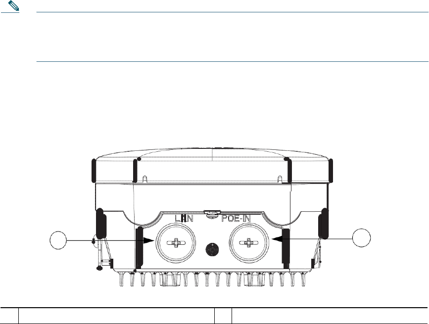
Figure 1 Access Point Bottom Connectors - AP 1532I
1 2
1
LAN port (covered)
2
PoE-in port (covered)
9
347848
347847
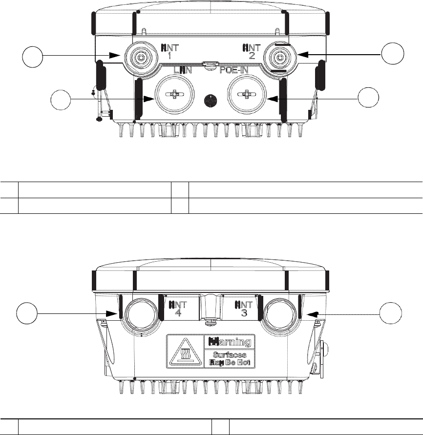
Figure 2 Access Point Bottom Connectors - AP 1532E
1 2
3 4
1
Antenna port 1
2
Antenna port 2
3
LAN port (covered)
4
PoE-in port (covered)
Figure 3 Access Point Top Connectors - AP 1532E
1 2
1
Antenna port 4 (covered)
2
Antenna port 3 (covered)
10
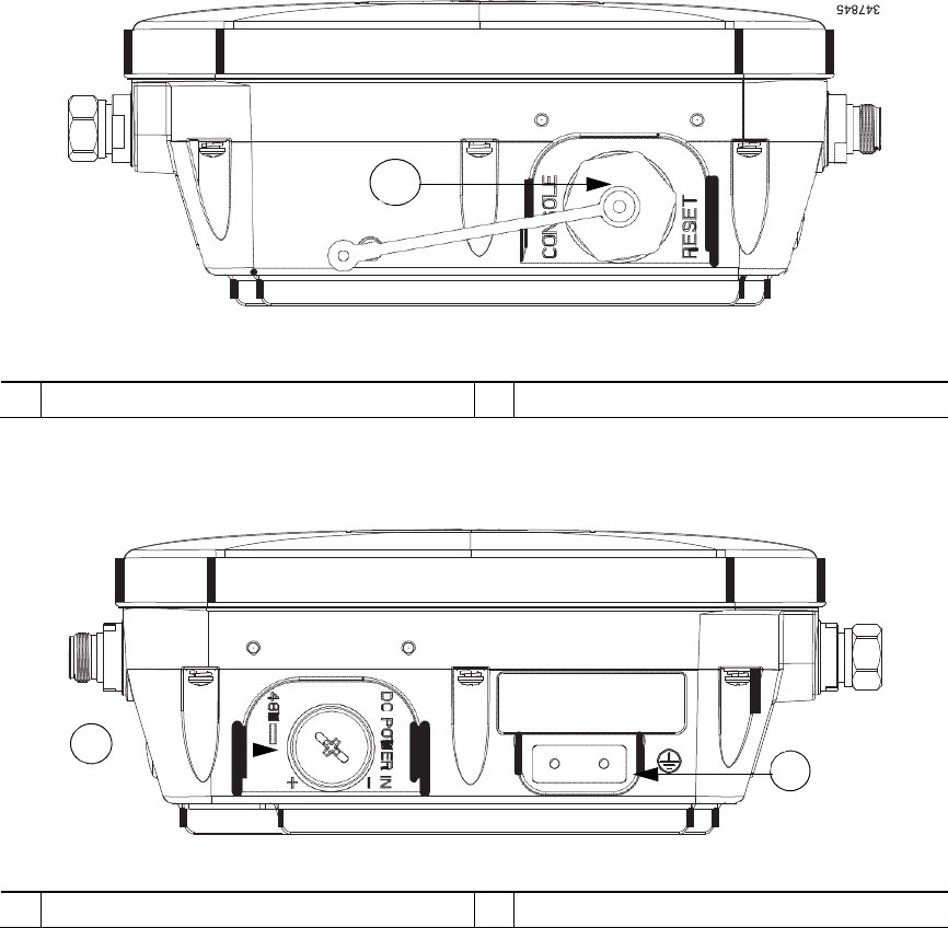
Figure 4 Access Point Left Side Connectors - Both AP 1532 Models
1
1
Console Port and Reset button (covered)
Figure 5 Access Point DC Power Connector and Ground Lug (Both AP 1532 Models)
1 2
347846
1
DC power port (covered)
2
Ground lug location

11
Radio Operation and Antennas
AP 1532I
The AP 1532I uses an Integrated Low Profile Dual-Band 2.4/5 GHz Dipole Antenna Array. The antenna
contains an array of three dual-band dipole antennas. The three dipole antennas are contained within this
single radome, thereby greatly reducing the antenna’s visual footprint, and greatly reducing the possibility of
snagging the antenna on the cable bundle, the RF cable, or test cables. The antennas operate over both 2.4
GHz and 5.25 – 5.85 GHz bands. Each of the three dipole antennas is a
dual-band antenna, covering both the 2.4 – 2.483 GHz band, and the 5.25 – 5.85 GHz bands. The antennas
have a peak gain of about 2 dBi at 2.4 GHz and 4 dBi at 5 GHz. The antenna unit is gray weatherproof
radome for outdoor operation.
The 1532I access point 802.11b/g/n radio is used primarily for local access and its 802.11a/n radio for
wireless backhaul in the Mesh.
The 2-GHz b/g/n radio operates in 2.4 GHz ISM band. It supports channels 1-11 in US, 1-13 in Europe, and
1-13 in Japan. It has three transmitters with a maximum total output power of 29dBm for 802.11b/g/n
operation. Output power is configurable to 5 levels. It has three receivers that enables maximum-ratio
combining (MRC).
The 5-GHz a/n radio operates in the UNII-2 band (5.25 - 5.35 GHz), UNII-2 Extended/ETSI band (5.47 -
5.725 GHz), and the upper ISM band (5.725 - 5.850 GHz). It has two transmitters with a maximum total
output power of 29 dBm for UNII-2 and Extended/ETSI bands for the A-domain. The total maximum output
power for the upper ISM band is 28 dBm for A-domain. Tx power settings will change depending on the
regulatory domain. Output power is configurable for 5 power levels in 3 dB steps. Its three receivers enable
maximum-ratio combining (MRC).
The 1532I access point is equipped with three integrated dual-band antennas with 3 dBi gain at 2 GHz and 5
dBi at 5 GHz.
Warning Only trained and qualified personnel should be allowed to install, replace, or service
this
equipment.
Statement
1030
12
347848
AP 1532E
The 1532E is equipped with two N-type radio frequency (RF) connectors (antenna ports 1 and 2) on the
bottom of the unit for external antennas to support multiple input multiple output (MIMO) operation in dual-
band mode, as shown in Figure 6. The 1532E must always be operated with the two external antennas
attached. When using the Cisco Aironet AIR-ANT2547V-N Dual-Band Omnidirectional Antenna, the 2.4-
and 5-GHz antennas connect directly to the access point, as shown in Figure 7. If the antennas are remotely
located, an appropriate low-loss RF coax cable should be used.
The 1532E access points are equipped with 4 N-type radio frequency (RF) connectors (antenna ports
1 and 2 on the bottom of the unit for 2-GHz and antenna ports 3 and 4 on the top of the unit for
5-GHz) for external antennas to support multiple input multiple output (MIMO) operation. The antenna ports
located of top of the 1532E are shown in Figure 3. The 1532E must always be operated with the appropriate
external antennas attached. Ports 1 and 2 can be used for Dual Band operation with a software configuration.
Note The antenna port caps must be removed for a uni-band antenna installation, but ports 3 and
4 should remain capped for a dual-band antenna installation to provide an IP67 seal
.
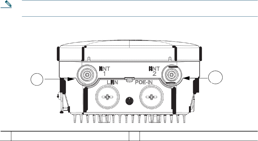
Figure 6 Access Point Bottom External Antenna Connectors - AP 1532E
1 2
1
N-Type Connector - Antenna port 4 (Tx/Rx)
2
N-Type Connector - Antenna port 6 (Tx/Rx)
13
347857
Antenna Mounting Configurations
The selection of the antenna is determined in the configuration of the product. The 1532E antennas can be
mounted on a wall, pole and/or tower mounted. See Antennas, page 6 for a list of supported antennas.
Figure 7 Access Point Dual-Band Omnidirectional Antennas - Installed Only on AP 1532E
1
2
1
Antenna connected to antenna port 1(Type-N
connector) (TX/RX)
2
Antenna connected to antenna port 2 (Type-N
connector) (TX/RX)

14
Note The FCC limits the amount of power this device can transmit. Power transmitted is a combination
of the amplification of the signal and the antenna gain. The access point has been designed to operate
with the Cisco provided antennas.
Power
Warning Installation of the equipment must comply with local and national electrical
codes.
Statement
1074
Warning This equipment must be externally grounded using a
customer-supplied
ground
wire
before power is applied. Contact the appropriate electrical inspection authority or
an
electrician if you are uncertain that suitable grounding is available. Statement
366
Warning Do not work on the system or connect or disconnect cables during periods of
lightning
activity. Statement
1001
The 1532E access point supports these power sources:
• DC power—48 volt
• Power-over-Ethernet (PoE)—56 VDC power injector (AIR-PWRINJ1500-2=)
Caution Do not place the power injector in an unprotected outdoor environment because water could
get into the power injector and cause a short circuit and possible fire.
Warning Connect the unit only to DC power source that complies with the Safety
Extra-Low
Voltage (SELV)
requirements
in IEC 60950 based safety standards Statement
1033

15
Power Injectors
The 1530 Series Access Points support the following power injectors:
• AIR-PWRINJ1500-2= — 100-240 VAC input, indoor use only
• AIR-PWRINJ4= — 100-240 VAC input, indoor use only (for the 1532E only)
Warning To reduce the risk of fire, use only No. 26 AWG or larger
telecommunication
line
cord.
Statement
1023
Caution To provide inline PoE, you must use the 1500 power injector (listed above). Other power
injectors, PoE switches, and 802.3af power sources cannot provide adequate power, which may
cause the access point to malfunction and cause over-current conditions at the power source. You
must ensure that the switch port connected to the access point has PoE turned off.
Caution The 1500 power injector (AIR-PWRINJ1500-2=) and the AIR-PWRINJ4= must be used in an
indoor environment only.
Caution When the access point is installed outdoors or in a wet or damp location, the AC branch circuit
that is powering the access point should be provided with ground fault protection (GFCI), as
required by Article 210 of the National Electrical Code (NEC).

16
Ethernet (PoE) Ports
The access point supports an Ethernet uplink port (PoE-In). The access point Ethernet uplink port uses an RJ-
45 connector (with weatherproofing) to link the access point to the 10BASE-T, 100BASE-T or
1000BASE-T network. The Ethernet cable is used to send and receive Ethernet data and to optionally supply
inline 56-VDC power from the power injector.
Tip The access point senses the Ethernet and power signals and automatically switches internal
circuitry to match the cable connections.
Warning To reduce the risk of fire, use only No. 26 AWG or larger
telecommunication
line
cord.
Statement
1023
The Ethernet cable must be a shielded outdoor rated Category 5e (CAT5e) or better
cable. The access point senses the Ethernet and power signals and automatically
switches internal circuitry to match the cable connections.

17
6 AP Pole/Wall Mount
This section provides instructions for installing your access point(s). Personnel installing the access
point(s) must understand wireless access points and bridging techniques and grounding methods.
Caution All installation methods for mounting an access point on any wall surface is subject to the
acceptance of local jurisdiction.
Installation Options
The 1530 Series Access Point can be wall, pole or tower mounted. There are two optional mounting kits: a
fixed mounting kit (AIR-ACC1530-PMK1=) and a pivoting mounting kit
(AIR-ACC1530-PMK2=).
Warning Only trained and qualified personnel should be allowed to install, replace, or service
this
equipment. Statement
1030
Warning Installation of the equipment must comply with local and national electric
codes.
Statement
1074
When mounting an access point on a horizontal or vertical surface, you must ensure that the access point is
oriented with the LED indicators pointing down (see Figure 10 on page 33). This positioning allows LEDs to
be visible to someone on the ground below the access point.
You must also ensure the access point is mounted in such a way as to ensure that all antenna ports and the
console port are accessible for future use.

18
Wall Mounting the Access Point with the Fixed Mounting
Kit
The optional fixed mounting kit contains a mounting bracket for wall mounting or pole mounting. You can
use the mounting bracket as a template to mark the positions of the mounting holes for your installation. You
then install the mounting plate, and attach the access point when you are ready. Table 1 lists the materials you
will need to provide in addition to the fixed mounting kit.
Table 1 Material Needed to Mount Access Point to a Vertical Wall
Materials Required
In Kit
Ground lug and screws (provided with access point)
Yes
Wall Mount Bracket
Yes
Four M6 x 12-mm Hex-head Bolts
Yes
Two stainless steel band clamps (adjustable 2"–5", 51 mm –
127 mm)
Yes
Two stainless steel band clamps(adjustable 5"–8", 127 mm –
203 mm)
Yes
Crimping tool for ground lug, Panduit CT0720 with
CD-720-1 die (http://onlinecatalog.paduit.com)
No
Four wall mounting screws
No
Four wall anchors (specified for all material)
No
Drill bit for wall anchors
No
Electric drill and standard screwdriver
No
#6 AWG ground wire
No
Shielded outdoor-rated Ethernet (CAT5e or better) cable
No
Grounding block
No
Grounding rod
No
10-mm box-end wrench or socket set
No
Caution The mounting surface, attaching screws and optional wall anchors must be able to support
a 50-lb (22.7 kg) static weight.
19
347852
To mount the access point on a vertical wall, follow these instructions:
Step 1 Use the mounting bracket as a template to mark four screw hole locations on the mounting surface.
See Figure 8 for the mounting bracket screw hole locations. Use the mounting slotted holes to attach
the unit to the wall.
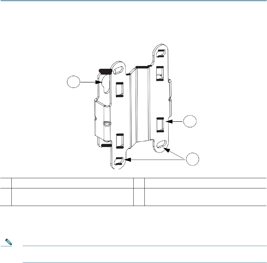
Figure 8 Mounting Bracket for Wall or Pole Mounting
1
2
3
1
Quick Mount Keyhole Slots (for AP use)
2
Mounting Slots (used with the band clamps)
3
Bracket Mount Holes (use bolts up to 1/4" or
6 mm in diameter)
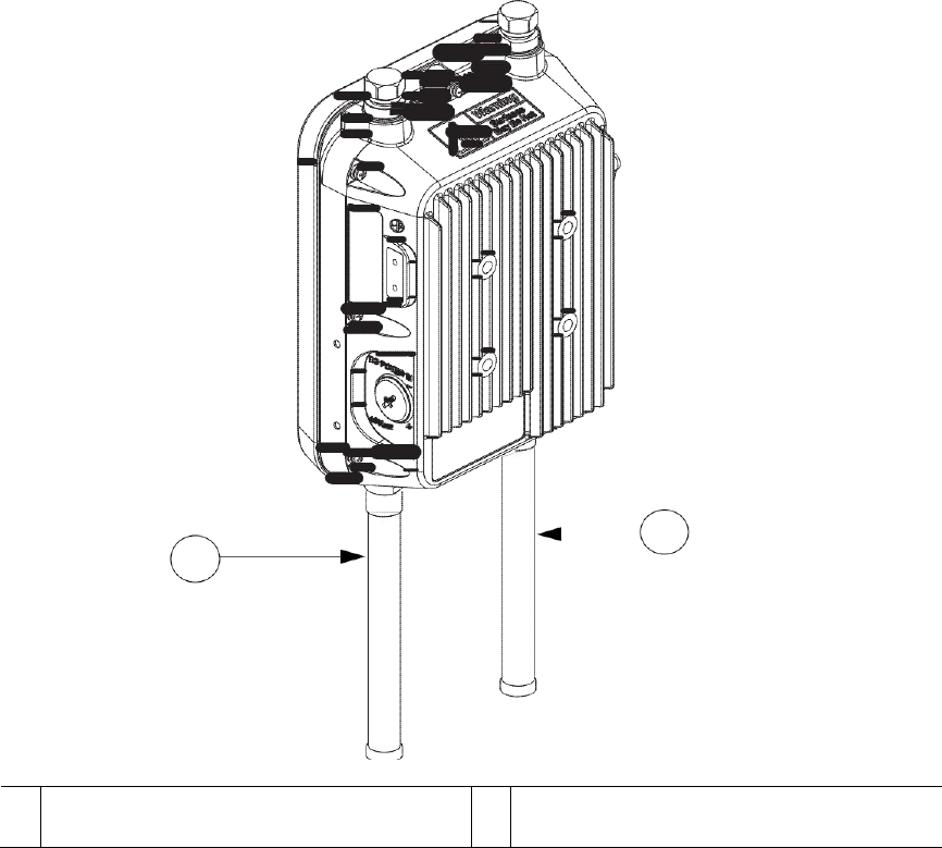
Step 2 Use four customer-supplied screws and optional screw-anchors to attach the mounting plate to the
mounting surface.
Note If necessary, use suitable screw anchors and an exterior-grade plywood backboard to mount the
access point to stucco, cement or drywall.
Step 3 Screw an M6 x12 mm bolt into each of the four support bolt holes on the back of the access point.
Do not screw the bolt all the way in; leave approximately a 0.13 inch (3.3 mm) space.
Step 4 Position the four bolts on the access point into the keyhole slots on the mounting bracket.
Step 5 Slide the access point down to sit securely in the quick mount notches.

20
Step 6 Using a 10mm wrench, secure the AP to the bracket by tighening the bolts to the bracket;
torque to 40 in-lbf.
Step 7 Continue with the Grounding the Access Point, page 23.
Pole Mounting the Access Point with the Fixed Mount
Kit
The optional fixed mounting kit contains a mounting bracket for wall mounting or pole mounting.This kit can
be used to install the access point on a pole, mast or streetlight. It supports metal, wood or fiberglass poles
from 2 to 8 inches in diameter.
Table 2 Materials Needed to Mount the AP on a Vertical Pole
Materials Required
In Kit
One wall mount bracket
Yes
Four M6 x12mm hex head bolts
Yes
Two stainless steel band clamps (adjustable 2"–5", 51–127
mm)
Yes
Two stainless steel band clamps (adjustable 5"–8", 127–203
mm)
Yes
10 mm box-end wrench
No
Outdoor rated shielded ethernet cable
No
Ground lug (provided with the access point)
Yes
Ground block and rod
No
Crimping tool for ground lug, Panduit CT-720 with CD-720-1
die (http://onlinecatalog.panduit.com)
No
#6 AWG ground wire
No
To mount the access point onto a vertical pole or streetlight pole, follow these steps:
Step 1 Select a mounting location on the pole to mount the access point. You can attach the access point
to any pole with a diameter from 2to 8 inches (5.1 to 20.1 cm).
Note If you will be using a streetlight power tap adapter, position the access point within
3 ft (1 m) of the outdoor light control. The AC/DC adapter must be used with street light
power tap.

21
Step 2 Determine which size of band clamp is needed based on the pole diameter. Slide the two clamps
through the top and bottom set of mounting slots (see Figure 8) and mount the bracket to the
pole.
Step 3 Wrap the band clamps around the pole and slide them into the second set of top and bottom
mounting slots on the bracket. Lightly tighten the clamps. Only tighten them enough to keep the
bracket from sliding down the pole.
Step 4 Screw an M6 bolt into each of the four bolt holes on the back side of the access point. Do not screw
the bolt in all the way. Leave a gap of about 0.13" (3.3mm).
Step 5 Position the four bolts on the access point into the bracket keyhole slots. Check to be sure that the
access point is properly seated in the slots.(See Figure 9)
Note The access point should be positioned with the LEDs on the bottom to allow viewing from
the ground.
Step 6 Using a 10mm wrench, tighten the four bolts that connect the access point to the bracket to a torque
of 40 in-lbf.
Step 7 Locate the access point to its final position. Tighten the band clamps with the wrench so that the
access point does not slide on the pole. Be sure that the clamps are tight enough that the AP does
not move.
Step 8 Continue with the Grounding the Access Point, page 23.
Zl.
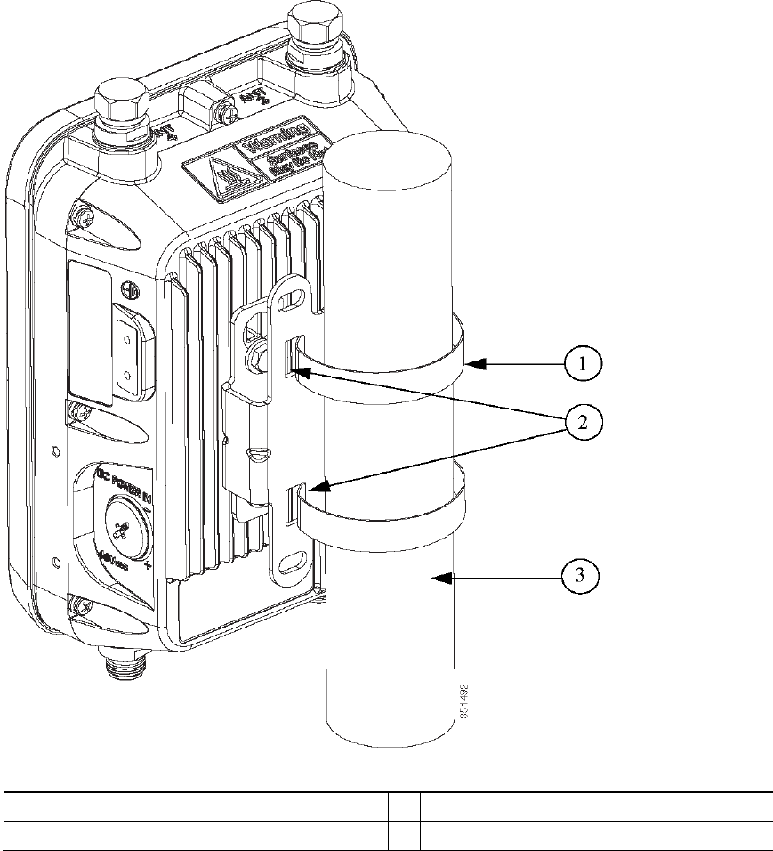
Figure 9 AP and Fixed Mount Kit Installed on a Pole
1
Metal Band
Strap
2
Mounting Slots
3
Pole

23
Grounding the Access Point
The access point must be grounded before connecting power.
Warning This equipment must be externally grounded using a
customer-supplied
ground
wire
before power is applied. Contact the appropriate electrical inspection authority or
an
electrician if you are uncertain that suitable grounding is available. Statement
366
Warning Installation of the equipment must comply with local and national electrical
codes.
Statement
1074
In all outdoor installations and when powering the access point with AC power, you must follow these
instructions to properly ground the access point:
Step 1 If using insulated 6-AWG copper ground wire, strip the insulation as required for the
grounding lug.
Step 2 Use the appropriate crimping tool to crimp the bare 6-AWG copper ground wire to the
supplied grounding lug.
Note The grounding lug and hardware used must comply with local and national electrical codes.
Step 3 Open the electrical joint compound (supplied), and apply a liberal amount over the metal surface
where the ground strap screw holes are located (see Figure 5).
Step 4 Connect the grounding lug to the access point grounding screw holes (see Figure 5) using the
supplied two Phillips head screws (M4 x 10 mm) with lock washers. Tighten the grounding screw
to 22 to 24 in. lbs (2.49 to 2.71 Nm).
Step 5 If necessary, strip the other end of the ground wire and connect it to a reliable earth ground, such as
a grounding rod or an appropriate grounding point on a metal streetlight pole that is grounded.

24
7 Preparing the Access Point
The access point is a radio device which is susceptible to common causes of interference that can reduce
throughput and range. Follow these basic guidelines to ensure the best possible performance:
• For information on planning and initially configuring your Cisco mesh network, refer to the Cisco
Wireless Mesh Access Points, Design and Deployment Guide, Release 7.6. These documents are
available on cisco.com.
• Do not install the access point in an area where structures, trees, or hills obstruct radio signals to and
from the access point.
• You can install the access point at any height, but best throughput is achieved when the access points
are mounted at the same height.
Note To perform path loss calculation and to determine how far apart to install access points, consult
an RF planning expert.
Note See the 1530 Series Hardware Installation Guide for information on conducting a site survey prior to
installing the access point.
Avoiding Damage to Radios in a Testing Environment
The radios on outdoor units (bridges) have higher transmit power levels than radios on indoor units (access
points). When you test radios in a link, you must avoid exceeding the maximum receive input level of the
receiver. At levels higher than the normal operating range and packet error rate (PER) performance of the
receiver is degraded. At even higher levels, the receiver can be permanently damaged.
To avoid receiver damage and PER degradation, you can use one of the following techniques:
• Separate the omnidirectional antennas by at least 2 ft (0.6 m) to avoid receiver damage or by at least 25
ft (7.6 m) to avoid PER degradation.
• Reduce the configured transmit power to the minimum level.
• Cable the radios together using a combination of attenuators, combiners, or splitters to achieve a total
attenuation of at least 60 dB.

25
For a radiated test bed, the following equation describes the relationships among transmit power, antenna
gain, attenuation, and receiver sensitivity:
txpwr + tx antenna gain + rx ant gain - [attenuation due to antenna spacing] < max rx
input level
Where:
txpwr = Radio transmit power level
tx gain = transmitter antenna gain
rx gain = receiver antenna gain
For a conducted test bed, the following equation describes the relationships among transmit power, antenna
gain, and receiver sensitivity:
txpwr - [attenuation due to coaxial RF Attenuator components] < max rx input level
(0 dbm)
Caution Under no circumstances should you connect the antenna port from one access point to the antenna
port of another access point without using an RF attenuator. If you connect antenna ports you
must not exceed the maximum survivable receive level of 0 dBm. Never exceed 0 dBm or damage
to the access point can occur. Using attenuators, combiners, and splitters having a total of at
least 60 dB of attenuation ensures that the receiver is not damaged and PER performance is not
degraded.
Before You Begin
Warning Read the installation instructions before connecting the system to the power
source.
Statement
1004
Before you begin the installation process:
• Become familiar with the procedures for mounting the access point (see the AP Pole/Wall Mount, page
17).
• Become familiar with the access point connections (Figure 1 on page 8, Figure 4 on page 10, and
Figure 5 on page 10).
• Verify that the switch you are using to connect the controller is configured properly.

26
8 Deploying the Access Point
The following portions of this manual address how to deploy the Access Point. There are several
deployment methods.
Warning Do not operate the unit near unshielded blasting caps or in an explosive
environment
unless the device has been modified to be especially qualified for such use. Statement
364
Controller-based Deployments
The access point is deployed on Layer 3 networks. Layer 3 is the default mode for a newly configured
wireless LAN controller. This guide assumes that you will be deploying your access point on a Layer
3 network and a DHCP server is available.
Before deploying the access point, make sure the controller to which the access point will associate is
properly configured by performing the following operations:
• Verify the wireless LAN controller software version
• Record the access point BVI MAC address (MAC address is located on the label on the side of the unit.)
• Enter the access point BVI MAC address to the wireless LAN controller filter list
Recording the Access Point MAC Address
Use a text file to record the MAC address of all the access points you intend to deploy in your network. Having
a file of the access point MAC addresses will be of considerable value for future testing. While you are
compiling the list, you might want to change the name of the access point to something you can easily
remember. The name can contain up to 32 characters. The following example, fisher_street:ea:co contains
the last four HEX characters of the access point MAC address.

27
Adding the Access Point MAC Address to the Wireless LAN Controller
Filter
List
The wireless LAN controller maintains an access point authorization MAC address list and responds to
discovery requests from access points on that list. To add the access point MAC address (or MAC addresses)
to the Wireless LAN controller filter list, follow these steps:
Step 1 If you are not logged onto the wireless LAN controller, log on now. The Summary page
appears.
Step 2 On the menu bar, click SECURITY. The Security RADIUS Authentication Server page
appears.
Step 3 Under AAA in the left frame, click MAC Filtering. The Security MAC Filtering page appears.
Step 4 Click New. The MAC Filters New page appears.
Step 5 Enter the MAC address of the access point in the MAC Address field. You can also use the
config macfilter add command to add a MAC filter entry to the controller.
Step 6 Select a WLAN ID or Any WLAN from the WLAN ID pop-up menu.
Step 7 Enter a description (32 characters maximum) of the access point in the Description field.
Step 8 Choose an interface from the Interface Name pop-up menu.
Step 9 Click Apply.
Step 10 Repeat this process to add other access points to the list.
Note You can also use the controller CLI command config macfilter add to add a MAC
filter entry on the controller.
Step 11 On the menu bar, click Monitor to return to the Monitor Summary page.
Verifying Controller Association
To verify that your access point is associated to the wireless LAN controller, perform these steps:
Step 1 Log into your controller web interface (https) using a web browser.
Step 2 Click Wireless and verify that your access point MAC address is listed under Ethernet MAC.
Step 3 Log out of the controller and close your web browser.

28
Deployment Notes
Using a DHCP Server in a Layer 3 Mesh
Network
To use a DHCP server in a Layer 3 mesh network, you must configure DHCP option 43 on the DHCP
server. After the controller is restarted, the access point receives IP addresses from the DHCP server.
Configuring DHCP Option 43
You can use DHCP Option 43 to provide a list of controller IP addresses to the access points, enabling each
access point to find and join a controller. This section contains a DHCP Option 43 configuration example on a
Microsoft Windows 2003 Enterprise DHCP server for use with Cisco Aironet lightweight access points.
Additional information about Microsoft DHCP Option 43 is available on Cisco.com at the following
URL:
http://www.cisco.com/en/US/tech/tk722/tk809/technologies_configuration_example09186a0080871
4fe.shtml
DHCP Option 43 server implementation information for Cisco IOS is available at cisco.com at the
following URL:
http://www.cisco.com/en/US/docs/wireless/technology/controller/deployment/guide/dep.html#wp106
8287
Note In DHCP Option 43, you should use the IP address of the controller management interface.
Note DHCP Option 43 is limited to one access point type per DHCP pool. You must configure a
separate DHCP pool for each access point type.
Cisco 1532 access points use the type-length-value (TLV) format for DHCP Option 43. DHCP servers must be
programmed to return the option based on the DHCP Vendor Class Identifier (VCI) string (DHCP Option
60) of the access point. The VCI string for the Cisco 1532 access point is
Cisco AP c1532.
The format of the TLV block for the 1532 access point is listed below:
• Type: 0xf1 (decimal 241)
• Length: Number of controller IP addresses * 4
• Value: List of WLC management interfaces

29
Configuring Option 43 for Cisco 1532 Access Po
ints
To configure DHCP Option 43 for Cisco 1532 access point in the embedded Cisco IOS DHCP server, follow
these steps:
Step 1 Enter configuration mode at the Cisco IOS CLI.
Step 2 Create the DHCP pool, including the necessary parameters such as default router and name server.
The commands used to create a DHCP pool are as follows:
ip dhcp pool pool
name
network
IP Network Netmask
default-router Default router
dns-server DNS Server
Where:
pool name is the name of the DHCP pool, such as AP1532.
IP Network is the network IP address where the controller resides, such as
10.0.15.1
Netmask is the subnet mask, such as 255.255.255.0
Default router is the IP address of the default router, such as 10.0.0.1
DNS Server is the IP address of the DNS server, such as 10.0.10.2
Step 3 Add the Option 60 line using the following syntax:
option 60 ascii “VCI string”
For the VCI string, use the value from Configuring DHCP Option 43, page 28. The quotation marks
must be included.
Step 4 Add the option 43 line using the following syntax:
option 43 hex hex string
The hex string is assembled by concatenating the TLV values shown below:
Type + Length + Value
Type is always f1(hex). Length is the number of controller management IP addresses times 4 in hex.
Value is the IP address of the controller listed sequentially in hex.
For example, suppose that there are two controllers with management interface IP addresses,
10.126.126.2 and 10.127.127.2. The type is f1(hex). The length is 2 * 4 = 8 = 08 (hex). The IP
addresses translate to 0a7e7e02 and 0a7f7f02. Assembling the string then yields
f1080a7e7e020a7f7f02.
The resulting Cisco IOS command added to the DHCP scope is listed below:
option 43 hex f1080a7e7e020a7f7f02

30
Autonomous Mode Configuration
The 1530 Series allows the Unified (controller-based) and Autonomous mode software to be loaded at the
factory on the same hardware part number. This eliminates the need for separate part numbers for controller-
based units and autonomous mode units.
At boot-up, the default mode is controller-based. The 1530 will power up and begin searching for a
controller. Once it joins the controller, it will download the active Unified image from the controller. This is
the same operation as other Cisco controller-based APs.
For Autonomous mode, the user should take the following steps:
Step 1 Power the AP and connect to the console.
Step 2 From the Command Line, enter:
AP # capwap ap autonomous (# means privileged EXEC mode)
Step 3 The system will respond with "Convert to Autonomous image. Proceed? (yes/[No]):"
Step 4 Type "yes" to confirm.
Step 5 The AP will then re-boot and load the Autonomous image. The unified image is erased.
Step 6 Once the 1530 has booted in autonomous mode, configuration of the AP can done by
following the procedure outlined here:
http://www.cisco.com/en/US/partner/docs/wireless/access_point/12.4_10b_JA/configuration/guid
e/scg12410b.html

31
9 In Case of Difficulty
Help is available from Cisco should you experience difficulties; however, before contacting Cisco, look for a
solution to your problem in the following places:
• The Troubleshooting section of this guide
• The Troubleshooting a Mesh Network troubleshooting guide found on cisco.com at
http://www.cisco.com/en/US/products/ps8368/prod_troubleshooting_guides_list.html
• The Tools and Resources section on the Technical Support and Documentation page at cisco.com
Follow these steps to contact the Technical Assistance Center on cisco.com:
Step 1 Open your browser and go to http://www.cisco.com/.
Step 2 Click Support. The Support page appears.
Step 3 Choose the link that best serves your support requirements.
Note Click My Tech Support if you are a registered user.
Step 4 Follow the instructions on the page.
Troubleshooting
Caution No serviceable parts inside. Do not open.
This section provides troubleshooting procedures for basic problems with the access point. For the most
up-to-date, detailed troubleshooting information, refer to the Cisco Support website at cisco.com.
32
Guidelines for Using the Access Point
You should keep these guidelines in mind when you use the access point:
• The access point supports Layer 3 CAPWAP communications with the controllers. In Layer 3 operation,
the access point and the controller can be on the same or different subnets. The access point
communicates with the controller using standard IP packets. Layer 3 operation is scalable and is
recommended by Cisco. Unless it has a static IP address, a Layer 3 access point on a different subnet than
the controller requires a DHCP server on the access point subnet and a route to the controller. The route
to the controller must have destination UDP ports 12222 and 12223 open for CAPWAP communications.
The routes to the primary, secondary, and tertiary controllers must allow IP packet fragments.
• Before deploying your mesh access points ensure that the following has been done:
– Your controllers are connected to switch ports that are configured as trunk ports.
– Your mesh access points are connected to switch ports that are configured as untagged access ports.
– A DHCP server is reachable by your mesh access points and has been configured with Option
43. Option 43 is used to provide the IP addresses of the Management Interfaces of your controllers.
Typically, a DHCP server can be configured on a Cisco Layer 3 switch or router.
– Optionally a DNS server can be configured to enable a local domain Cisco CAPWAP controller
(CISCO-CAPWAP-CONTROLLER.<local
domain>) to resolve to the IP address of the Management
Interface of your controller.
– Your controllers are configured and reachable by the mesh access points.
– Your controllers are configured with the MAC addresses of the mesh access points.
33
347848
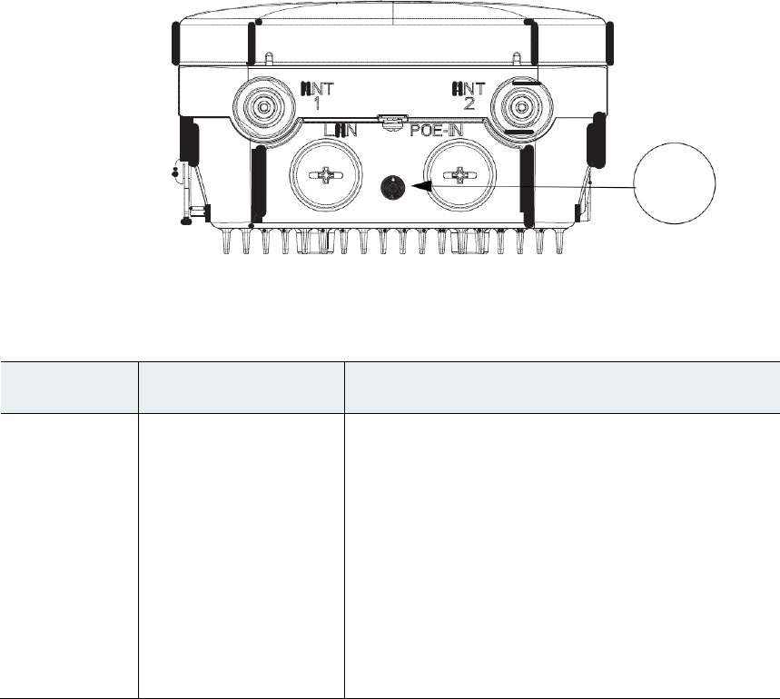
Checking the LEDs
One LED is located between the LAN and PoE-In connectors. It indicates the status of the access point power,
uplinks and radios. Figure 10 identifies and describes the LED functions. Table 3 provides additional LED
signal information.
Figure 10 Access Point LEDs –Shown on the Bottom of AP 1532E
LED
Indicator
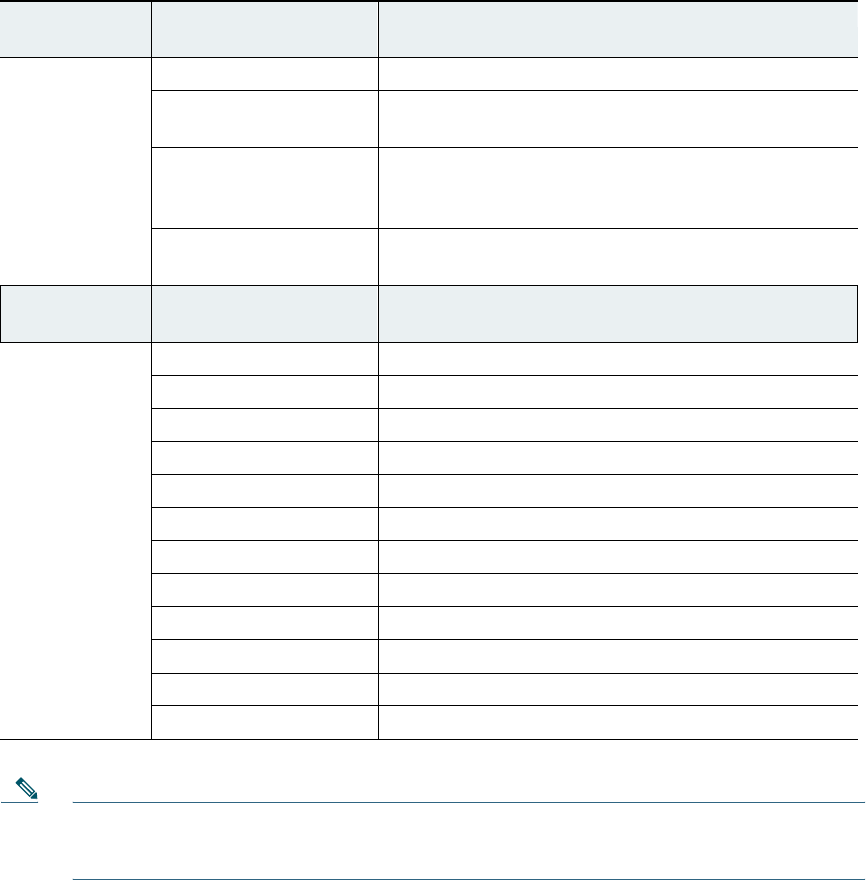
Table 3 Access Point LED Signals
LED Message
Type
Color
Meaning
Boot loader
status sequence
Blinking Green
Boot loader status sequence:
• DRAM memory test in progress
• DRAM memory test OK
• Board initialization in progress
• Initializing FLASH file system
• FLASH memory test OK
• Initializing Ethernet
• Ethernet OK
• Starting Cisco IOS
• Initialization successful

34
LED Message
Type
Color
Meaning
Boot loader
warnings
Blinking Amber
Configuration
recovery is in progress (the MODE button
has been pushed for 2-3 seconds)
Solid Red
There is an Ethernet failure or an image recovery (the
MODE button has been pushed for 20-30 seconds)
Blinking Green
An image recovery is in progress (the MODE button has
been released)
Boot loader
errors
Solid Red
There has been a DRAM memory test failure
Blinking Red and Amber
There has been a FLASH file system failure
Blinking Red and Off
This sequence may indicate any of the following:
• Environment variable failure
• Bad MAC address
• Ethernet failure during image recovery
• Boot environment failure
• No Cisco image file
• Boot failure
Cisco IOS
errors
Solid Red
There has been a software failure; a disconnect then
reconnect of the unit power may resolve the issue
Cycling through Red,
Green, Amber and Off
This is a general warning of insufficient inline power.
Association
status
Chirping (short blips)
Green
This status indicates a normal operating condition. The
unit is joined to a controller, but no wireless client is
associated with it.
Solid Green
Normal operating condition with at least one wireless
client associated with the unit
35
LED Message
Type
Color
Meaning
Operating
Status
Blinking Amber
A software upgrade is in progress
Cycling through Green,
Red and Amber
Discovery/join process is in progress
Rapidly cycling through
Red, Green, Amber and
Off
This status indicates that the Access Point location
command has been invoked.
Blinking Red
This status indicates that an Ethernet link is not
operational
Alignment
Mode
Color
Signal Level (dBm)
Solid Green
> –44
Fast blinking Green
–47 to –44
Medium blinking Green
–50 to –47
Solid Amber
–53 to –50
Fast blinking Amber
–57 to –53
Medium blinking Amber
–60 to –57
Slow blinking Amber
–63 to –60
Slow blinking Red
–66 to –63
Medium blinking Red
–69 to –66
Fast blinking Red
–72 to –69
Solid Red
–75 to –72
Off
< –75
Note Regarding LED status colors, it is expected that there will be small variations in color intensity and
hue from unit to unit. This is within the normal range of the LED manufacturer’s specifications and
is not a defect.
Misconfigured Access Point IP address
IP address misconfiguration can occur when you are re-addressing a segment of your mesh network and you
start at the mesh access point connected to the wired network (RAP). To avoid this problem, always start the
IP address changes from the farthest access point and work your way back to the root access point. This
problem might also happen if you move equipment such as uninstalling amesh access point and then
redeploying with a different IP subnet in another physical location on the mesh network.
Another option to fix this misconfigured IP address is to physically take a controller in Layer 3 mode with a
root access point to the location of the misconfigured mesh access point. Set the bridge group name for the
root access point to match the misconfigured access point. Add the access point MAC address to the filter list
of the controller. When the misconfigured access point appears in the Summary page of the controller,
configure the access point with an IP address.
If you are using a static IP address on the access point and plan on redeploying the access point on another
subnet, perform a clear config command from the controller for that access point while it is joined before
you remove it from the network.
Verifying the Controller MAC Filter List
Prior to activating your access point, you must ensure that the access point MAC address has been added to
the controller MAC Filter list and that Mac Filter List is enabled. To view the MAC addresses added to the
controller MAC filter list and ensure the MAC filter list is enabled, you can use the controller CLI or the
controller GUI.
Controller CLI
Use the show macfilter summary controller CLI command to view the MAC addresses added to the
controller filter list.
Controller GUI
Log into your controller web interface (HTTPS) using a web browser and click SECURITY > AAA > MAC
Filtering to view the MAC addresses added to the controller filter list. Then click Wireless > Mesh to
ensure the MAC filter list is enabled.
37
10 Declarations of Conformity and Regulatory Information
This section provides declarations of conformity and regulatory information for the Cisco 1532 Access Point.
Regulatory Domains
The 1530 series supports the following regulatory domains (shown as “x” in the model numbers):
• -A FCC/North America, including Canada, Mexico, and some South American countries
• -C Malaysia, Egypt
• -D India
• -E ETSI and many European, Middle Eastern, and African countries (EMEA)
• -F Indonesia
• -H China
• -K Korea
• -M Kuwait and Saudi Arabia
• -N Non-FCC, including Hong Kong, Panama, and Mexico
• -Q Japan
• -R Russia
• -S Singapore
• -T Taiwan
• -Z Brazil, Australia and New Zealand
For the latest details and accurate listing of country homologation, refer to “Table 3. 802.11abgn
Outdoor Access Points” on the Wireless-LAN-Compliance-Status page at:
http://www.cisco.com/en/US/prod/collateral/wireless/ps5679/ps5861/product_data_sheet0900aecd80
537b6a.html#wp9005628
38
FCC Safety Compliance Statement
The FCC with its action in ET Docket 96-8 has adopted a safety standard for human exposure to radio
frequency (RF) electromagnetic energy emitted by FCC certified equipment. When used with approved Cisco
Aironet antennas, Cisco Aironet products meet the uncontrolled environmental limits found in OET-65 and
ANSI C95.1, 1991. Proper installation of this radio according to the instructions found in this manual will
result in user exposure that is substantially below the FCC recommended limits.
Declaration of Conformity for RF Exposure
This access point product has been found to be compliant to the requirements set forth in CFR 47
Section 1.1307 addressing RF Exposure from radio frequency devices as defined in Evaluating
Compliance with FCC Guidelines for Human Exposure to Radio Frequency Electromagnetic Fields.
Use is permitted with antenna gain not exceeding 8 dBi in both the 2.4 GHz and 5 GHz band, as described
in filing, with a minimum separation distance of 20 cm (8") between the antenna and all persons during
normal operation.
Use is permitted with antenna gain not exceeding 13 dBi in the 2.4 GHz and 14 dBi in the 5 GHz band, as
described in filing, with a minimum separation distance of 50 cm (20") between the antenna and all persons
during normal operation.
Only antennas provided by Cisco for use with the product should be installed. The use of any other antennas
may cause damage to the access points or violate regulatory emission limits and will not be supported by
Cisco.
Declaration of Conformity with Regard to the EU Directive 1999/5/EC
(R&TTE Directive)
This declaration is only valid for configurations (combinations of software, firmware and hardware)
provided and/or supported by Cisco Systems. The use of software or firmware not supported/provided by
Cisco Systems may result that the equipment is no longer compliant with the regulatory requirements.

39
Manufacturers Federal Communication Commission Declaration of
Conformity Statement
Tested To Comply
With FCC Standards
FOR HOME OR OFFICE USE
Models
Certification Numbers
AIR-CAP1532I-A-K9
FCC ID: LDK102090P
AIR-CAP1532E-A-K9
FCC ID: LDK102089P
Manufacturer:
Cisco Systems, Inc.
170 West Tasman Drive San
Jose, CA 95134-1706 USA
This device complies with Part 15 rules. Operation is subject to the following two conditions:
1. This device may not cause harmful interference, and
2. This device must accept any interference received, including interference that may cause undesired
operation.
This equipment has been tested and found to comply with the limits of a Class B digital device, pursuant to
Part 15 of the FCC Rules. These limits are designed to provide reasonable protection against harmful
interference when the equipment is operated in a residential environment. This equipment generates, uses,
and radiates radio frequency energy, and if not installed and used in accordance with the instructions, may
cause harmful interference. However, there is no guarantee that interference will not occur. If this equipment
does cause interference to radio or television reception, which can be determined by turning the equipment
off and on, the user is encouraged to correct the interference by one of the following measures:
• Reorient or relocate the receiving antenna.
• Increase separation between the equipment and receiver.
• Connect the equipment to an outlet on a circuit different from which the receiver is connected.
40
• Consult the dealer or an experienced radio/TV technician.
Caution The Part 15 radio device operates on a
non-interference
basis with other devices operating at this
frequency when using the integrated antennas. Any changes or modification to the product
(including the use of non-Cisco antennas specified for this model) provided not expressly
approved by Cisco could void the user’s authority to operate this device.
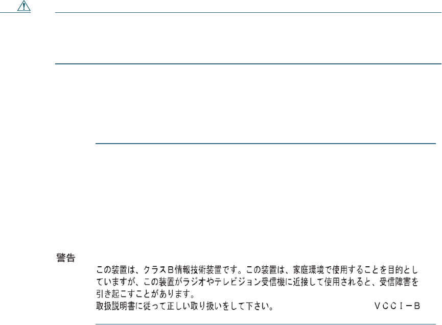
VCCI Statement for Japan
Warning
This is a Class B product based on the standard of the Voluntary
Control
Council for Interference from Information Technology Equipment (VCCI). If
this
is used near a radio or television receiver in a domestic environment, it
may
cause radio interference. Install and use the equipment according to
the
instruction
manual.
41
208697
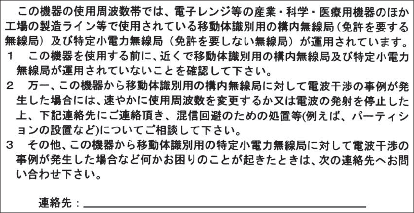
Guidelines for Operating Cisco Access Points in Japan
This section provides guidelines for avoiding interference when operating Cisco Aironet access points in
Japan. These guidelines are provided in both Japanese and English.
Japanese Translation
03-6434-6500
English Translation
This equipment operates in the same frequency bandwidth as industrial, scientific, and medical devices such as
microwave ovens and mobile object identification (RF-ID) systems (licensed premises radio stations and
unlicensed specified low-power radio stations) used in factory production lines.
1. Before using this equipment, make sure that no premises radio stations or specified low-power radio
stations of RF-ID are used in the vicinity.
2. If this equipment causes RF interference to a premises radio station of RF-ID, promptly change the
frequency or stop using the device; contact the number below and ask for recommendations on
avoiding radio interference, such as setting partitions.
3. If this equipment causes RF interference to a specified low-power radio station of RF-ID, contact the
number below.
Contact Number: 03-6434-6500

42
Statement 371—Power Cable and AC Adapter
English Translation
When installing the product, please use the provided or designated connection cables/power cables/AC
adaptors. Using any other
cables/adaptors
could cause a malfunction or a fire. Electrical Appliance and
Material Safety Law prohibits the use of UL-certified cables (that have the “UL” shown on the code) for any
other electrical devices than products designated by CISCO. The use of cables that are certified by Electrical
Appliance and Material Safety Law (that have “PSE” shown on the code) is not limited to CISCO-
designated products.
Industry Canada
Canadian Compliance Statement
AIR-CAP1532I-A-K9
IC: 2461B-102090P
AIR-CAP1532E-A-K9
IC: 2461B-102089P
This Class B Digital apparatus meets all the requirements of the Canadian Interference-Causing
Equipment Regulations.
Cet appareil numerique de la classe B respecte les exigences du Reglement sur le material broilleur du
Canada.
This device complies with Class B Limits of Industry Canada. Operation is subject to the following two
conditions:
1. This device may not cause harmful interference, and
2. This device must accept any interference received, including interference that may cause undesired
operation.
43
Cisco Aironet Access Points are certified to the requirements of RSS-210. The use of this device in a system
operating either partially or completely outdoors may require the user to obtain a license for the system
according to the Canadian regulations. For further information, contact your local Industry Canada office.
This device has been designed to operate with antennas having a maximum gain of 13 dBi for 2.4 GHz and 14
dBi for 5 GHz. Antennas having a gain greater than 6 dB are strictly prohibited for use with this device. The
required antenna impedance is 50 ohms.
To reduce potential radio interference to other users, the antenna type and its gain should be so chosen that the
equivalent isotropically radiated power (EIRP) is not more than that permitted for successful communication.
European Community, Switzerland, Norway, Iceland, and
Liechtenstein
Models:
AIR-CAP1532I-E-K9
AIR-CAP1532E-E-K9
This device has been designed to operate with antennas having a maximum gain of 13 dBi for 2.4 GHz and 14
dBi for 5 GHz. Antennas having a gain greater than 14 dBi are strictly prohibited for use with this device.
The required antenna impedance is 50 ohms.

44
Declaration of Conformity with regard to the R&TTE
Directive
199915/EC
&
Medical Directive 93/42/EEC
6bJlrapCKH
[
Bul
garian]
Tosa
o6opy11saue OTrosapll
ua
CbuteCTBemne
lf3HCKB3
1
Hill
H nplinOlKHMH KJJayJn
ua
}l
HpeKTli
s
a 1999/5/EC.
Cesky
[Czech]:
Toto
7,.afizeni
jc
v souladu
se
7.
a
klad
n
i
mi
po'.adavky
a
ostatnimi odpovidajicirni
ustanovcnimi
Sm¢m
i
cc
1999/5
/
EC
.
Dansk
[
Dani
sh
]
:
Dette udstyr
er
i
overenss
t
emmelse
med
de
V<£sentlige krav
og
andre relevante besternmelser
i
Direktiv
19
99
/
5/E
F
.
Deut
sc
h
[
German)
:
Dieses Gerlit entspricht den grundlegenden Anfordenmgen und
den
weiteren
entsprechenden
Vorgaben
der
Richtlinie 1999
/
5
/
EU
.
Eesti
[
Es
t
onian]
:
See seade
vastab direktiivi 1999
/
5
/
EO
oluli
s
t
ele
nouete
l
eja
teist
e
l
e
asjakohastele
s.iite
t
ele.
Engli
s
h
:
This eq
uipment
is in
com
p
l
iance
with the essential requirements
and
o
t
her
relevant
provisions
of Directive 1999/5/EC.
Espa
1
1
o
l
[Spanish]:
Este equipo cumple
con
los
requi
si
t
e
s
esenciales
asi
como con
o
t
ras disposiciones
de
I
a
Direc
t
iva 1999/5/CE.
EMT
J
V
I
"il
[Greek):
Aur6
0
cl;on),\Oll
£1\rQI cr£
OUl16piP<l)<ITJ
£
n
0\J<HWOEHQ; nQitl]0'£1KQI
aJ
O'XE"riKt
o
J
ara
£
n1Oo•rria
1
999
/
5
/
EC
.
Fra
n
ais
[
French]
:
Cet
apparei
l
est
confonne aux exige
n
ces
essentielles
e
t
aux
autres
d
i
sposition
s
pertinentes
de
I
a
Direc
t
ive
1
999
/
5
/
EC
.
islenska
[Icelandic):
Italiano
[
Ita
li
a
n
]
:
!>etta ta::ki
cr
samkv
a::m
t
grunnkrOfum
og Mntm
viociga
ndi
a
kva:oum Ti
l
skipuna
r 1999/5/EC.
Questo apparato
e
confonne
ai
r
eq
uisiti
essenzia
l
i ed agli altri
principi sanciti
dalla Direttiva
1999/5/CE.
Latvieu
[
Latvian
]
:
Si
iekllrta
atbi
l
st
.
OirektTvas
1
999/5/EK
bii
t
iska
j
llm
prasTbllm un
ci
t
iem
ar to saistilajiem
noteikum
ic
m
.

45
The following standards were applied:
EMC—EMC-EN 301.489-1 v1.8.1; EN 301.489-17 v2.1.1
Health & Safety—EN60950-1: 2005; EN 50385: 2002
Radio—EN 300 328 v 1.7.1; EN 301.893 v 1.5.1
The conformity assessment procedure referred to in Article 10.4 and Annex III of Directive 1999/5/EC
has been followed.

46
This device also conforms to the EMC requirements of the Medical Devices Directive 93/42/EEC.
Note This equipment is intended to be used in all EU and EFTA countries. Outdoor use may be restricted
to certain frequencies and/or may require a license for operation. For more details, contact Cisco
Corporate Compliance.
The product carries the CE Mark:
Declaration of Conformity for RF Exposure
United
States
This system has been evaluated for RF exposure for Humans in reference to ANSI C 95.1 (American
National Standards Institute) limits. The evaluation was based on ANSI C 95.1 and FCC OET Bulletin
65C rev 01.01. The minimum separation distance from the antenna to general bystander is 8" (20 cm) for
antenna gains up to 8 dBi and 20" (50 cm) for antenna gains from 8.1 to 14 dbi to maintain compliance.
Canada
This system has been evaluated for RF exposure for Humans in reference to ANSI C 95.1 (American
National Standards Institute) limits. The evaluation was based on RSS-102 Rev 2. The minimum separation
distance from the antenna to general bystander is 8" (20 cm) for antenna gains up to 8 dBi and 20" (50 cm) for
antenna gains from 8.1 to 14 dbi to maintain compliance.
European Union
This system has been evaluated for RF exposure for Humans in reference to the ICNIRP (International
Commission on Non-Ionizing Radiation Protection) limits. The evaluation was based on the EN
50385 Product Standard to Demonstrate Compliance of Radio Base stations and Fixed Terminals for Wireless
Telecommunications Systems with basic restrictions or reference levels related to Human Exposure to Radio
Frequency Electromagnetic Fields from 300 MHz to 40 GHz. The minimum separation distance from the
antenna to general bystander is 8" (20 cm) for antenna gains up to 8 dBi and 20" (50 cm) for antenna gains
from 8.1 to 14 dbi.
47
Australia
This system has been evaluated for RF exposure for Humans as referenced in the Australian Radiation
Protection standard and has been evaluated to the ICNIRP (International Commission on
Non-Ionizing Radiation Protection) limits. The minimum separation distance from the antenna to general
bystander is 8" (20 cm) for antenna gains up to 8 dBi and 20" (50 cm) for antenna gains from
8.1 to 14 dbi.
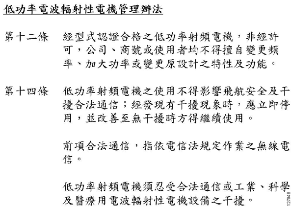
Administrative Rules for Cisco Access Points in Taiwan
This section provides administrative rules for operating Cisco access points in Taiwan. The rules for all
access points are provided in both Chinese and English.
Chinese Translation

48
English Translation
Administrative Rules for Low-power Radio-Frequency Devices
Article 12
For those low-power radio-frequency devices that have already received a type-approval, companies,
business units or users should not change its frequencies, increase its power or change its original features
and functions.
Article 14
The operation of the low-power radio-frequency devices is subject to the conditions that no harmful
interference is caused to aviation safety and authorized radio station; and if interference is caused, the user
must stop operating the device immediately and can't re-operate it until the harmful interference is clear.
The authorized radio station means a radio-communication service operating in accordance with the
Communication Act.
The operation of the low-power radio-frequency devices is subject to the interference caused by the
operation of an authorized radio station, by another intentional or unintentional radiator, by industrial,
scientific and medical (ISM) equipment, or by an incidental radiator.
Chinese Translation
49
English Translation
Low-power Radio-frequency Devices Technical Specifications
4.7
Unlicensed National Information Infrastructure
4.7.6
The U-NII devices shall accept any interference from legal communications and shall not
interfere the legal communications. If interference is caused, the user must stop operating the
device immediately and can't re-operate it until the harmful interference is clear.
4.7.7
Manufacturers of U-NII devices are responsible for ensuring frequency stability such that an
emission is maintained within the band of operation under all conditions of normal operation as
specified in the user manual.
Operation of Cisco Aironet Access Points in Brazil
This section contains special information for operation of Cisco Aironet access points in Brazil.
Access Point Models
AIR-CAP1532I-Z-K9
AIR-CAP1532E-Z-K9
Portuguese Translation
Este equipamento opera em caráter secundário, isto é, não tem direito a proteção contra interferência
prejudicial, mesmo de estações do mesmo tipo, e não pode causar interferência a sistemas operando em
caráter primário.
English Translation
This equipment operates on a secondary basis and consequently must accept harmful interference,
including interference from stations of the same kind. This equipment may not cause harmful interference
to systems operating on a primary basis.
Declaration of Conformity Statements
All the Declaration of Conformity statements related to this product can be found at the following
location: http://www.ciscofax.com.