Cisco Systems 102104 Cisco Aironet 802.11ac Dual Band Outdoor Access Points User Manual 1560hig
Cisco Systems Inc Cisco Aironet 802.11ac Dual Band Outdoor Access Points 1560hig
UserManual.wiki
>
Cisco Systems
>
102104 User Manual
1560hig_edit
Navigation menu
Upload a User Manual
Namespaces
Wiki Guide
HTML
PDF
Info
Views
User Manual
Discussion / Help
Navigation
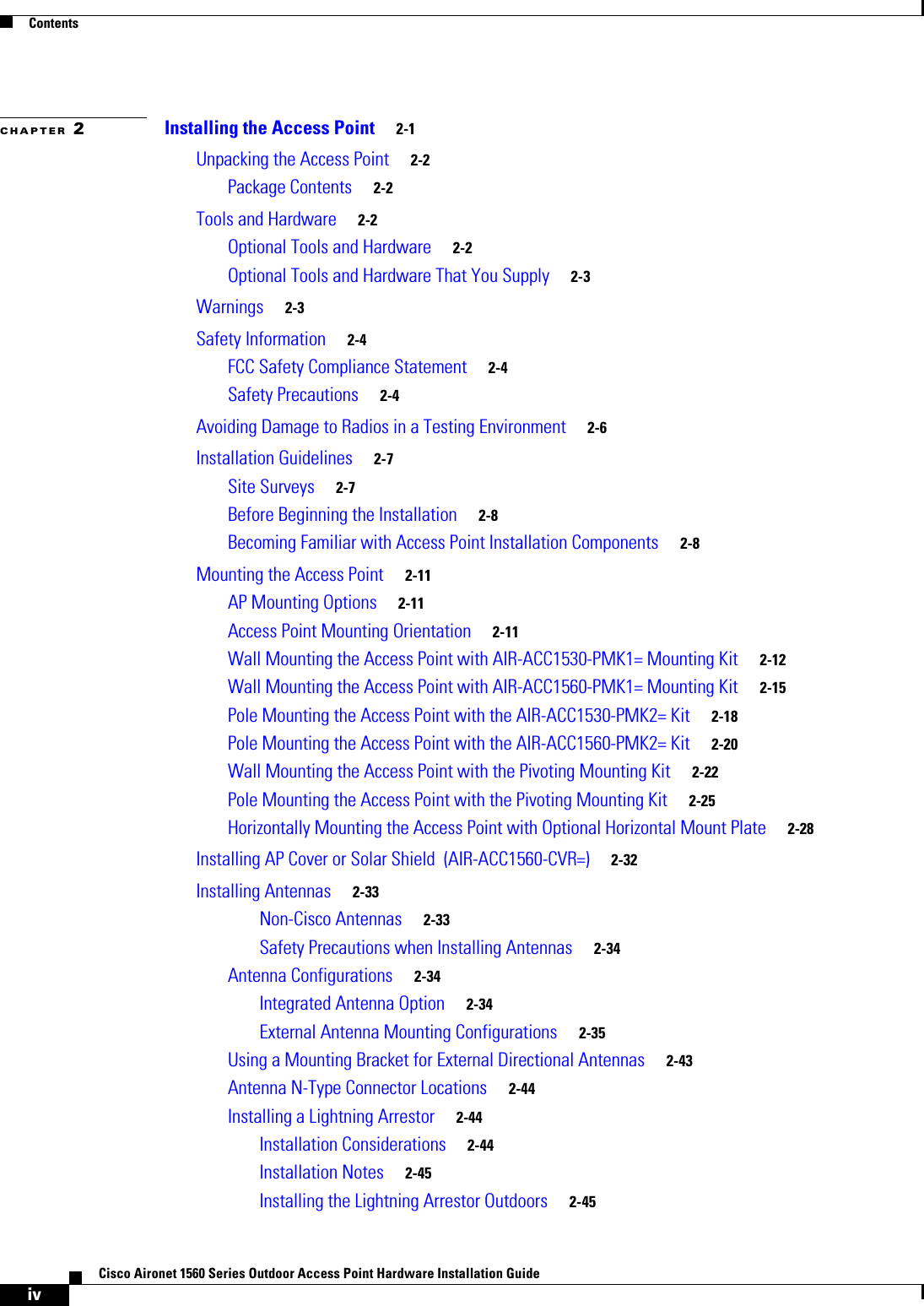
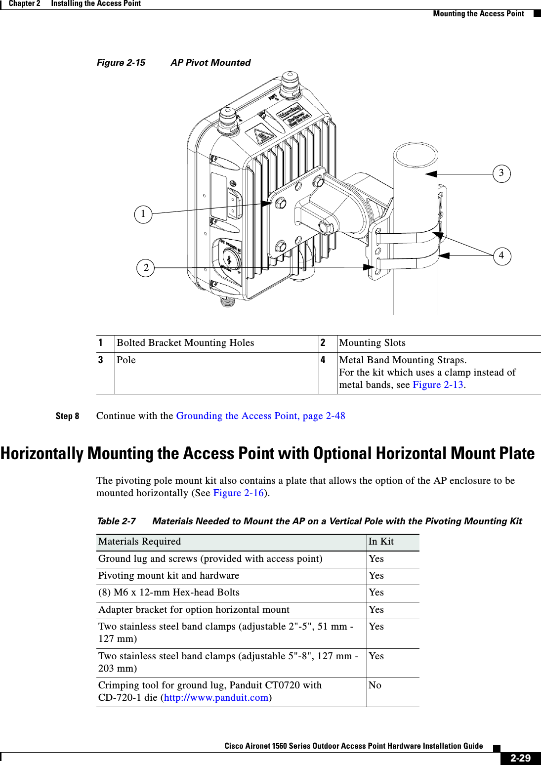
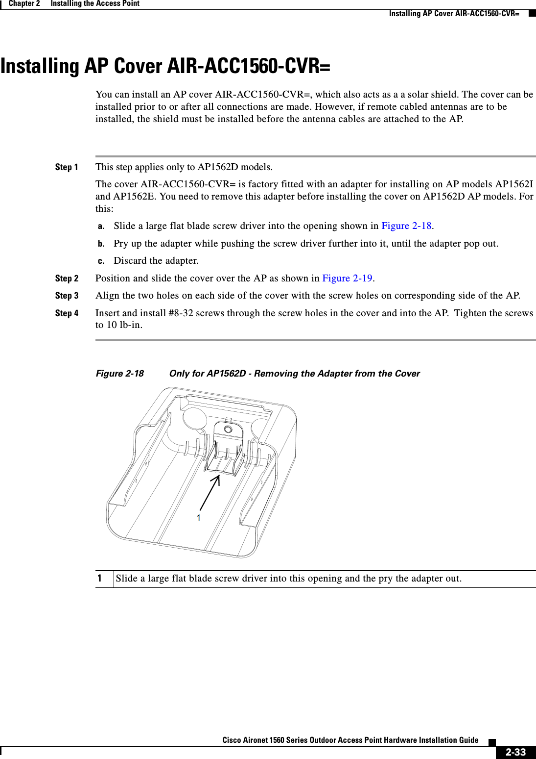
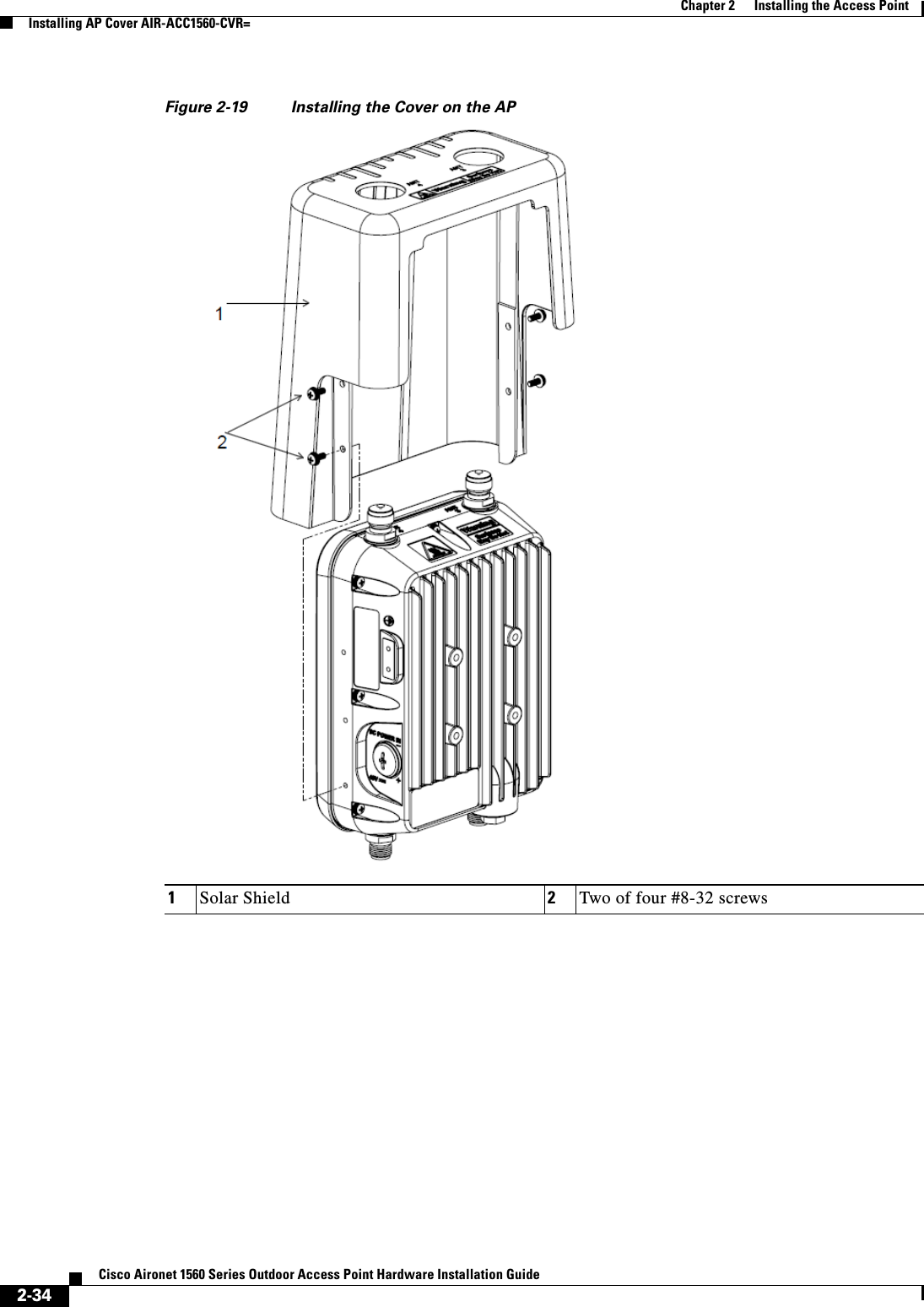
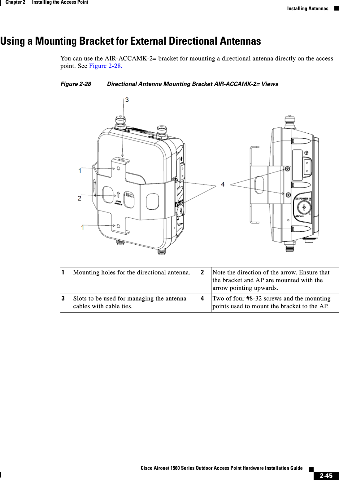
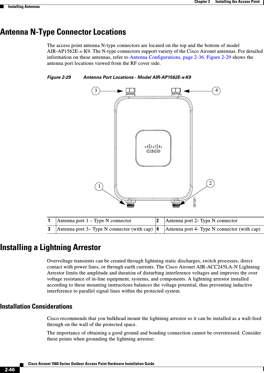
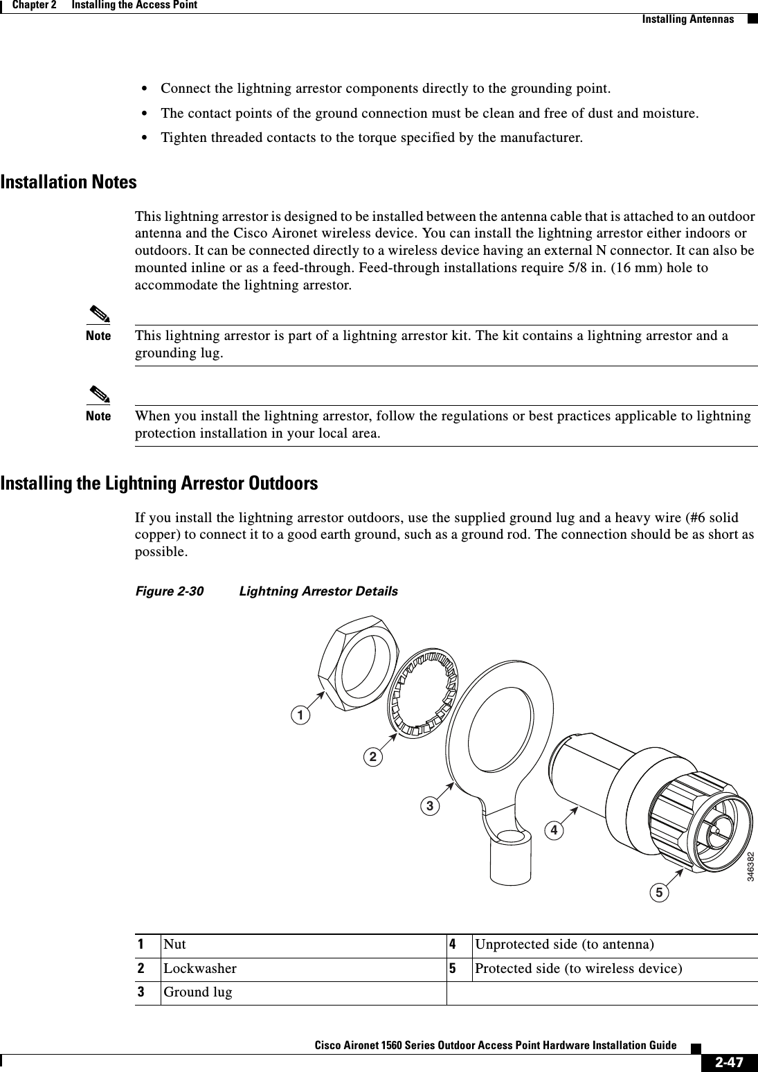
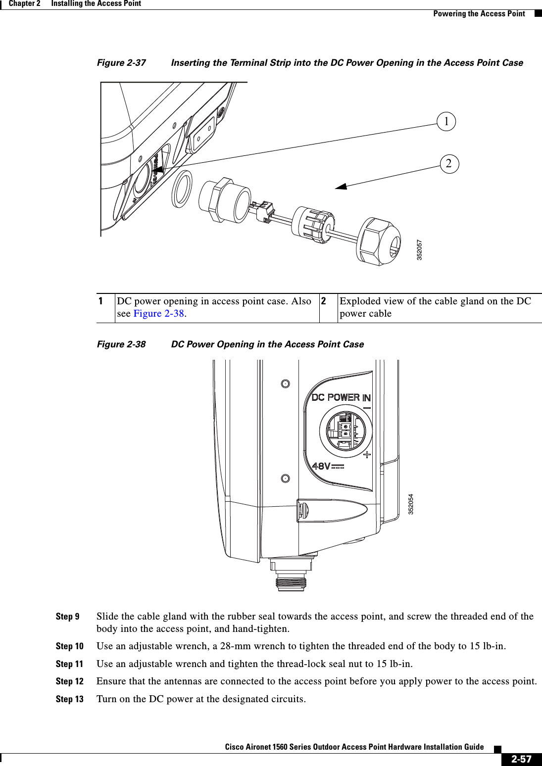
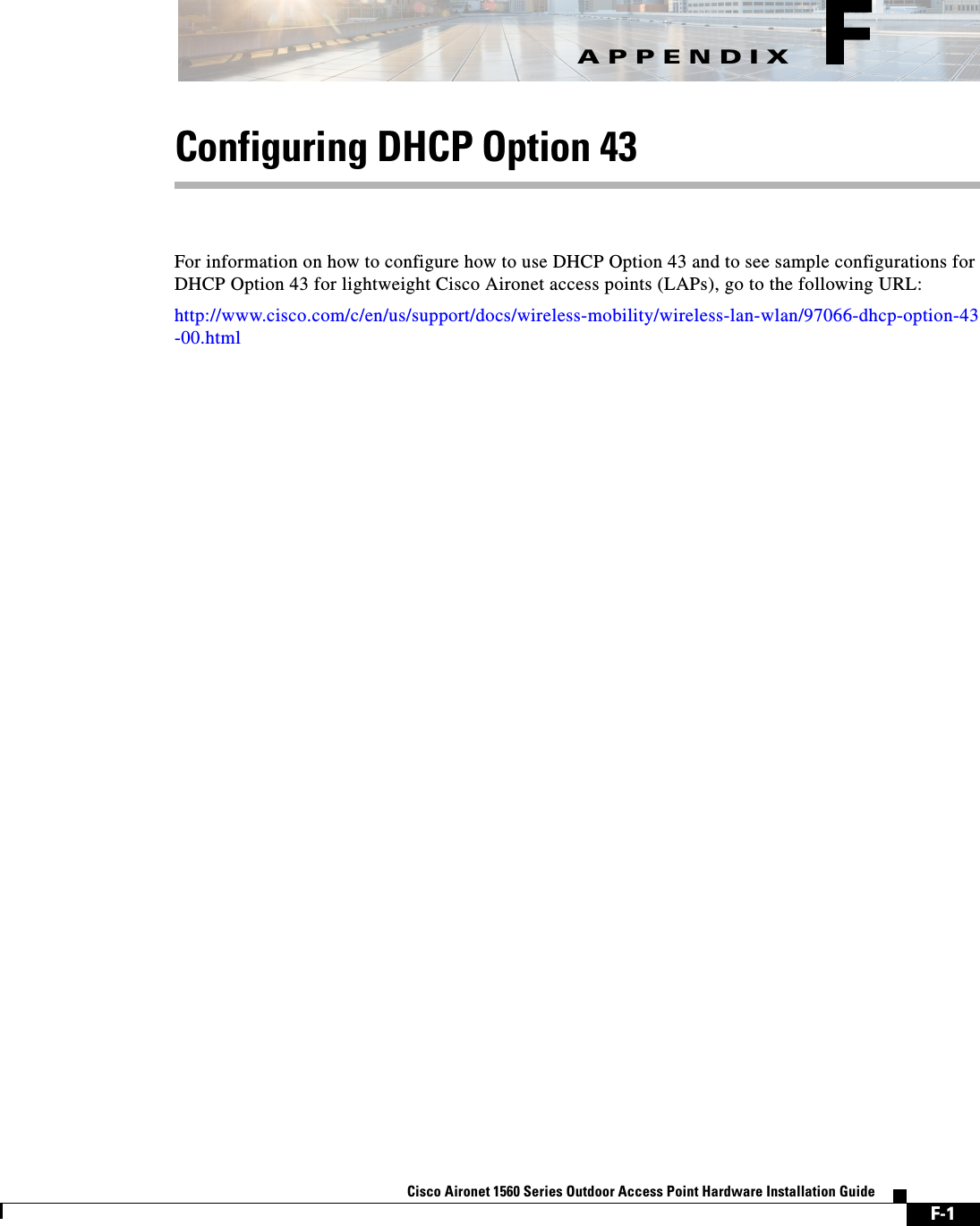
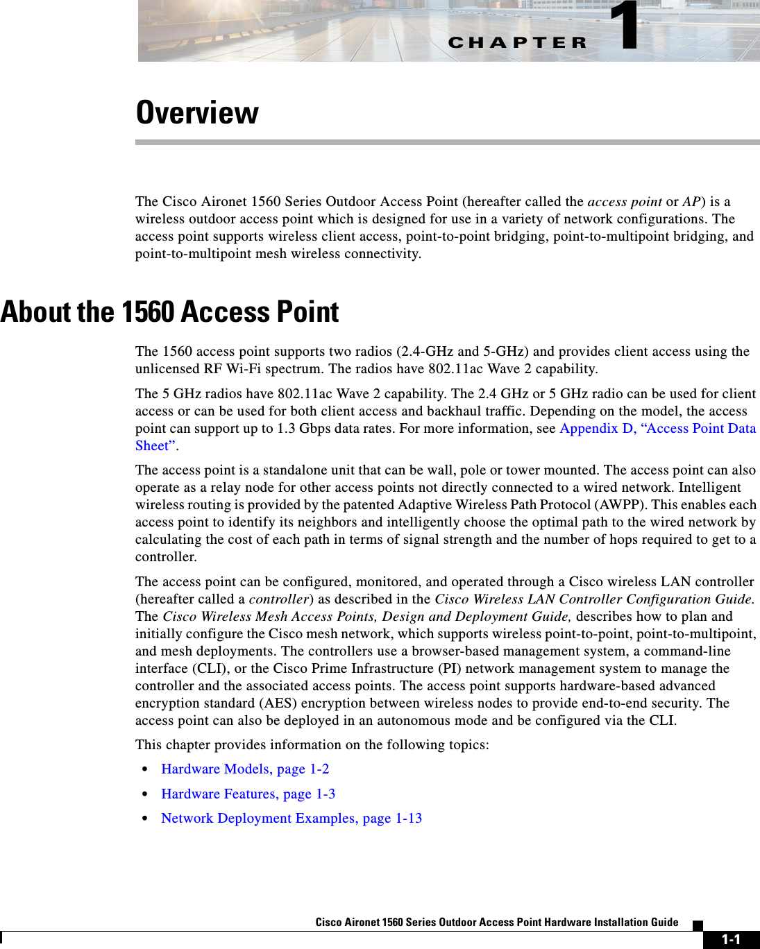
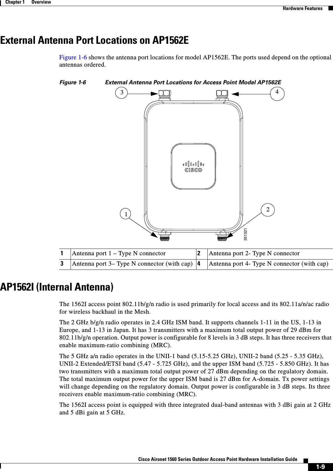
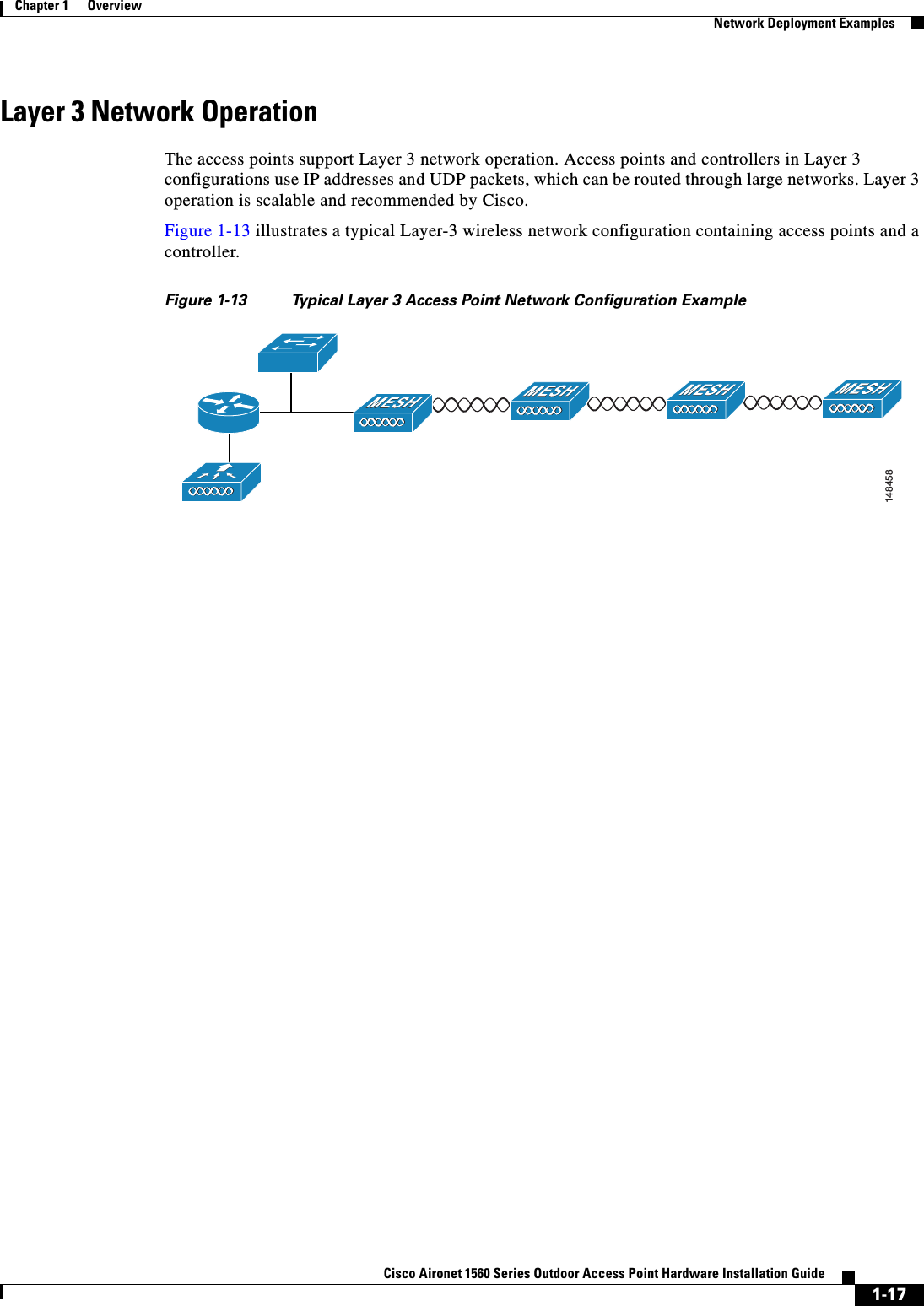
![viiiCisco Aironet 1560 Series Outdoor Access Point Hardware Installation Guide ConventionsThis publication uses the following conventions:Notes use the following conventions:Chapter 3 Troubleshooting Provides basic troubleshooting procedures for the access point. Appendix A Translated Safety Warnings Indicates how to access the document that provides translations of the safety warnings that appear in this publication.Appendix B Declarations of Conformity and Regulatory InformationDescribes the regulatory conventions to which the access point conforms and provides guidelines for operating access points in Japan.Appendix C Channels and Power Levels Indicates how to access the document that lists the access point radio channels and the maximum power levels supported by the world regulatory domains.Appendix D Access Point Data Sheet Lists technical specifications for the access point.Appendix E Access Point Pinouts Describes the connector pinouts for the access point.Appendix F Configuring DHCP Option 43Describes the procedure to configure DHCP Option 43.Chapter Title DescriptionConvention Descriptionboldface font Commands, command options, and keywords are in boldface.italic font Arguments for which you supply values are in italics.[ ] Elements in square brackets are optional.screen font Terminal sessions and information the system displays are in screen font.boldface screen font Information you must enter is in boldface screen font.italic screen font Arguments for which you supply values are in italic screen font.^ The symbol ^ represents the key labeled Control. For example, the key combination ^D in a screen display means hold down the Control key while you press the D key.< > Nonprinting characters, such as passwords, are in angle brackets.](https://usermanual.wiki/Cisco-Systems/102104/User-Guide-3170826-Page-8.png)
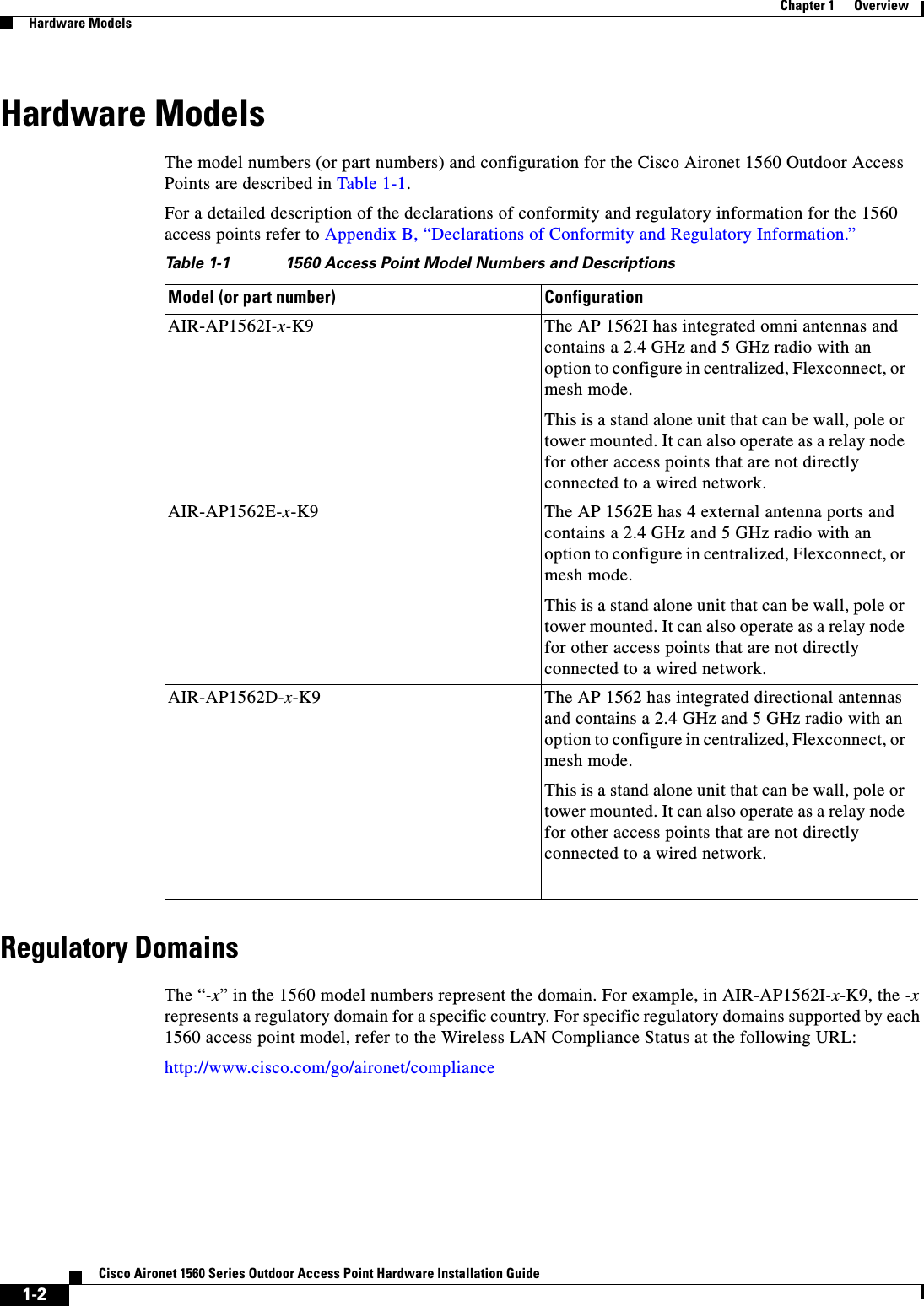

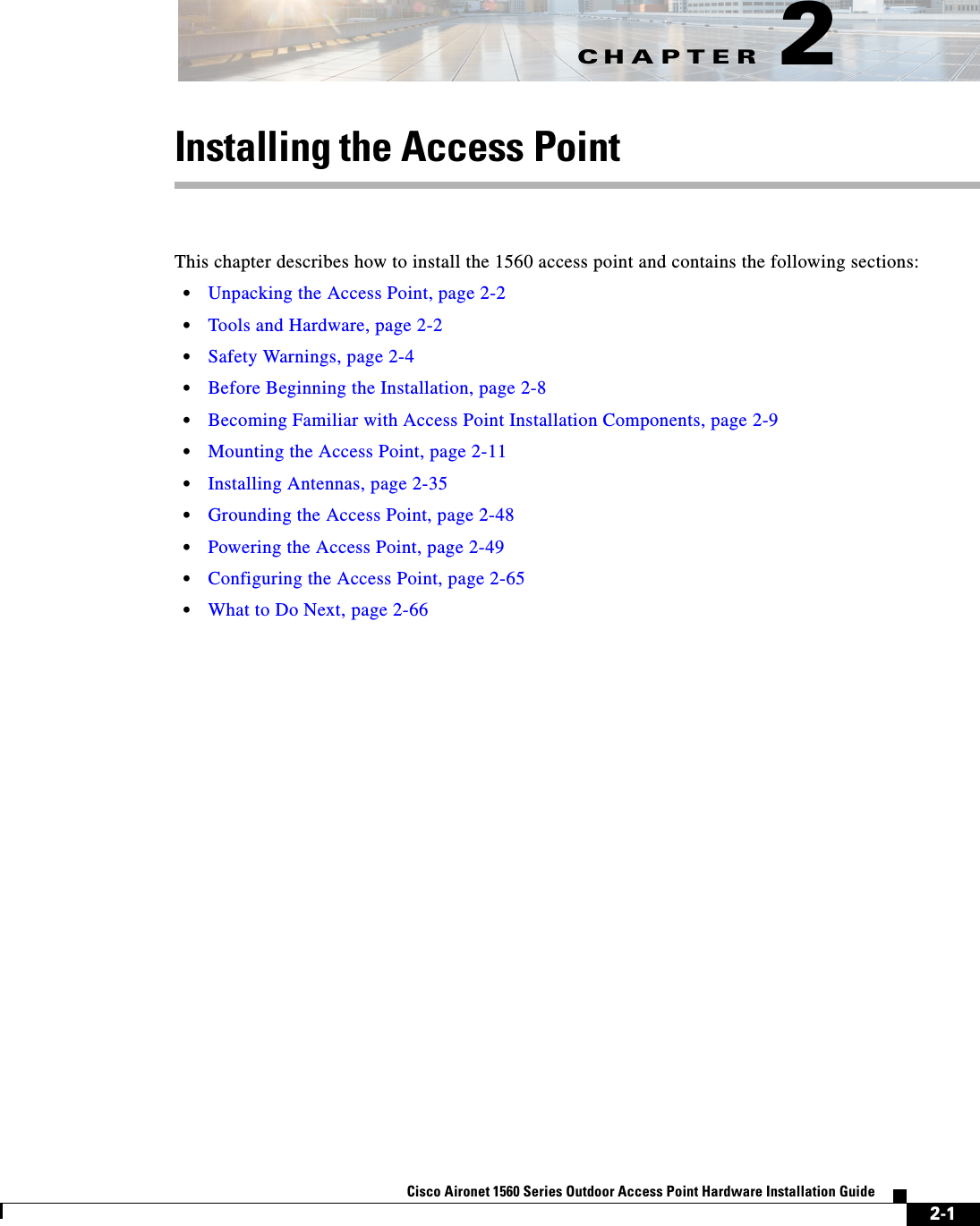
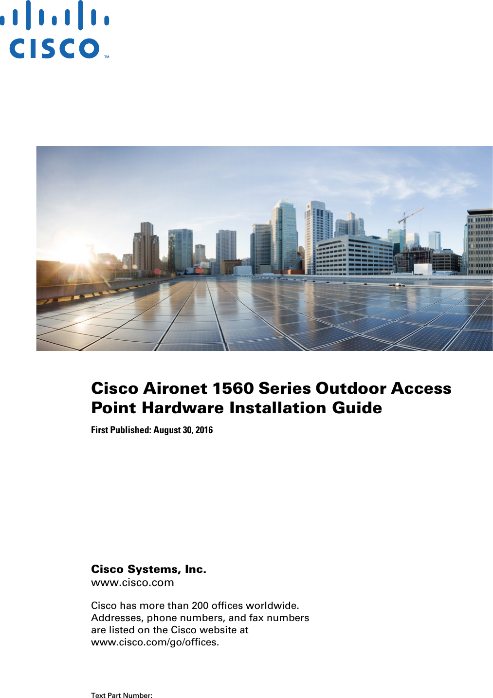
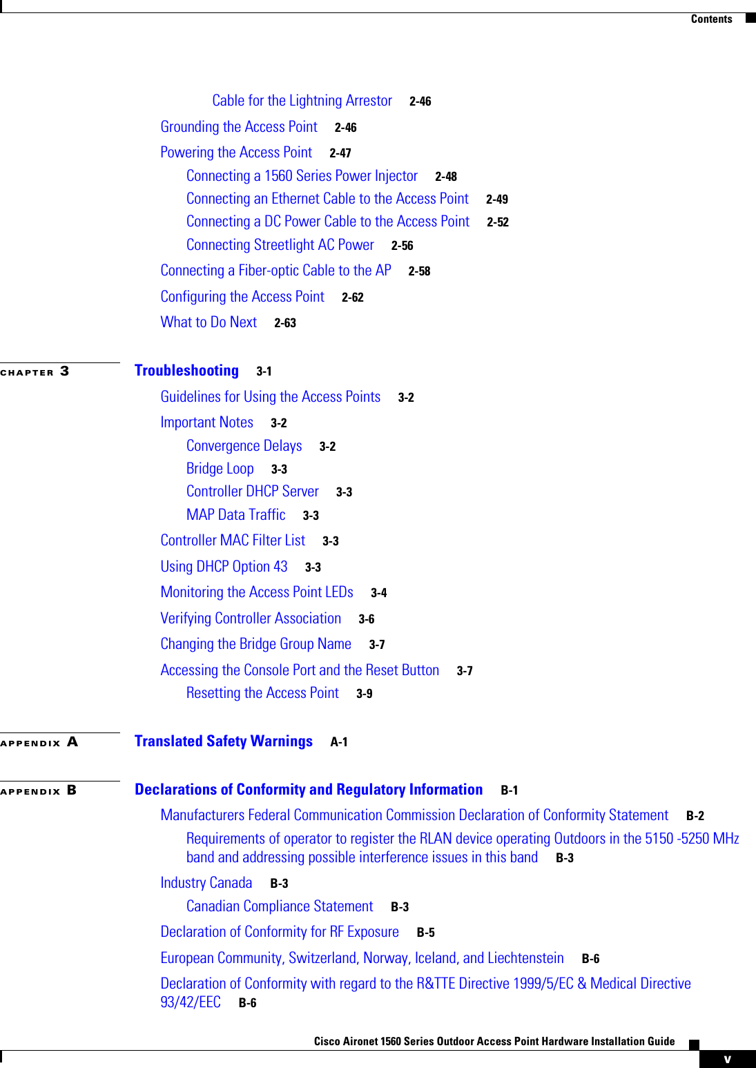
![2-6Cisco Aironet 1560 Series Outdoor Access Point Hardware Installation Guide Chapter 2 Installing the Access PointSafety WarningsCaution Before connecting or disconnecting a power cord, you must remove power from the power cord using a suitable service disconnect.For safety and to achieve a good installation, please read and follow these safety precautions:•Select your installation site with safety, as well as performance in mind. Remember: electric power lines and phone lines look alike. For safety, assume that any overhead line can kill. •Call your electric power company. Tell them your plans, and ask them to come look at your proposed installation. •Plan your installation carefully and completely before you begin. Successful raising of a mast or tower is largely a matter of coordination. Each person should be assigned to a specific task and should know what to do and when to do it. One person should be in charge of the operation to issue instructions and watch for signs of trouble.•When installing the access point and antennas, remember:–Do not use a metal ladder.–Do not work on a wet or windy day.–Do dress properly—shoes with rubber soles and heels, rubber gloves, long sleeved shirt or jacket.•Use a rope to lift the access point. If the assembly starts to drop, get away from it and let it fall. •If any part of the antenna system should come in contact with a power line, do not touch it or try to remove it yourself. Call your local power company. They will remove it safely. If an accident should occur, call for qualified emergency help immediately.Avoiding Damage to Radios in a Testing EnvironmentThe radios on outdoor units (bridges) have higher transmit power levels than radios on indoor units (access points). When you test high-power radios in a link, you must avoid exceeding the maximum receive input level for the receiver. At levels above the normal operating range, packet error rate (PER) performance is degraded. At even higher levels, the receiver can be permanently damaged. To avoid receiver damage and PER degradation, you can use one of the following techniques:•Separate the omnidirectional antennas by at least 2 ft (0.6 m) to avoid receiver damage or by at least 25 ft (7.6 m) to avoid PER degradation.Note These distances assume free space path loss and are conservative estimates. Required separation distances for damage and performance degradation levels in actual deployments are less if conditions are not non-line-of-sight.•Reduce the configured transmit power to the minimum level.•Use directional antennas, and keep them away from each other.•Cable the radios together using a combination of attenuators, combiners, or splitters to achieve a total attenuation of at least 60 dB.For a radiated test bed, the following equation describes the relationships among transmit power, antenna gain, attenuation, and receiver sensitivity:txpwr + tx gain + rx gain - [attenuation due to antenna spacing] < max rx input level](https://usermanual.wiki/Cisco-Systems/102104/User-Guide-3170826-Page-40.png)
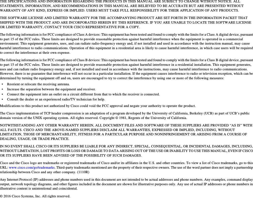
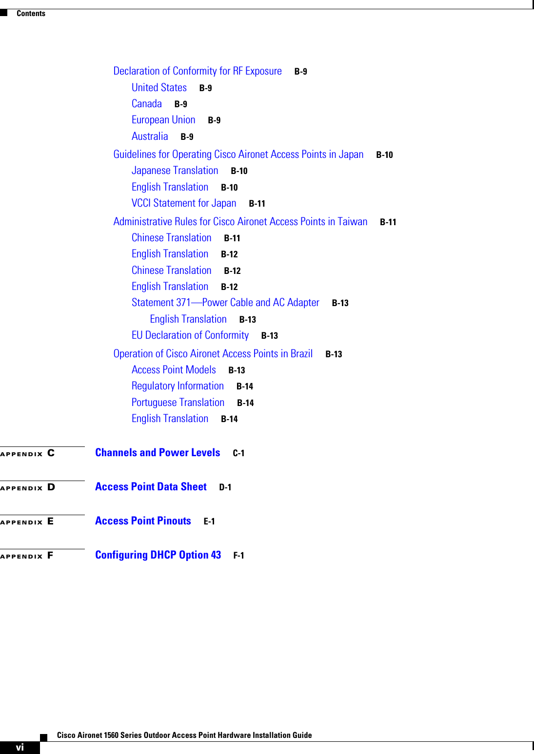
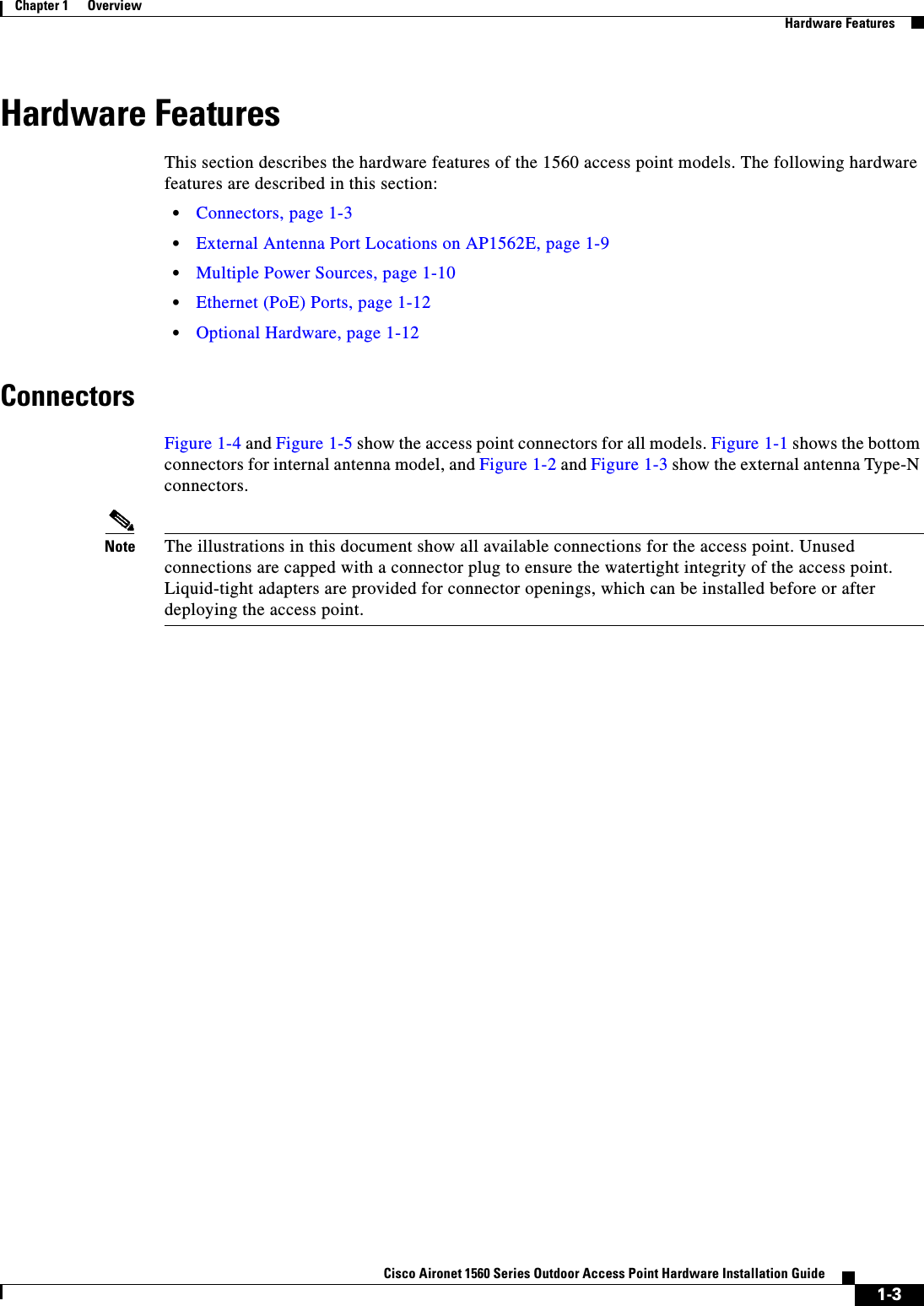
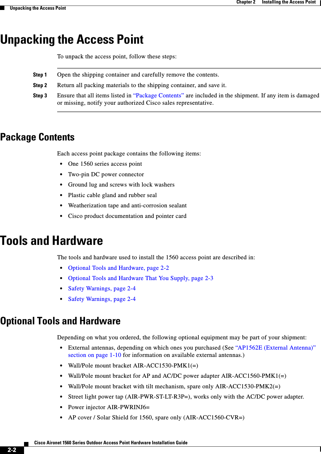
![2-7Cisco Aironet 1560 Series Outdoor Access Point Hardware Installation Guide Chapter 2 Installing the Access PointSafety WarningsWhere:txpwr = Radio transmit power leveltx gain = transmitter antenna gainrx gain = receiver antenna gainFor a conducted test bed, the following equation describes the relationships among transmit power, antenna gain, and receiver sensitivity:txpwr - [attenuation due to coaxial components] < max rx input levelCaution Under no circumstances should you connect the antenna port from one access point to the antenna port of another access point without using an RF attenuator. If you connect antenna ports, you must not exceed the maximum survivable receive level of 0 dBm. Never exceed 0 dBm, or damage to the access point can occur. Using attenuators, combiners, and splitters having a total of at least 60 dB of attenuation ensures that the receiver is not damaged and that PER performance is not degraded.Installation GuidelinesBecause the access point is a radio device, it is susceptible to common causes of interference that can reduce throughput and range. Follow these basic guidelines to ensure the best possible performance:•For information on planning and initially configuring your Cisco Mesh network, refer to the Cisco Wireless Access Points, Design and Deployment Guide, Release 7.3.•Review the FCC guidelines for installing and operating outdoor wireless LAN devices at http://www.cisco.com/c/en/us/products/collateral/routers/3200-series-rugged-integrated-services-routers-isr/data_sheet_c78-647116.html.•Perform a site survey before beginning the installation.•Install the access point in an area where structures, trees, or hills do not obstruct radio signals to and from the access point.•The access points can be installed at any height, but best throughput is achieved when all the access points are mounted at the same height. We recommend installing the access points no higher than 40 feet to allow support for wireless clients on the ground.•The Console port is under a sealed plugs Inspect the seal of the plug at the time of installation. Every time the plug is removed or replaced, properly tighten it. Tighten the plug to 15 lbf-in. If you do not tighten the plug properly, it will not meet IP67 criteria, and may lead to water leaking into the unit.•If the DC power port, SFP port, or the PoE-In port is not in use, then the port’s covering plug must be tightened to 12.5 lbf-in torque. Otherwise, it may lead to water leaking into the access point.Note To calculate path loss and to determine how far apart to install access points, consult an RF planning expert.Site SurveysEvery network application is a unique installation. Before installing multiple access points, you should perform a site survey to determine the optimum use of networking components and to maximize range, coverage, and network performance.](https://usermanual.wiki/Cisco-Systems/102104/User-Guide-3170826-Page-41.png)
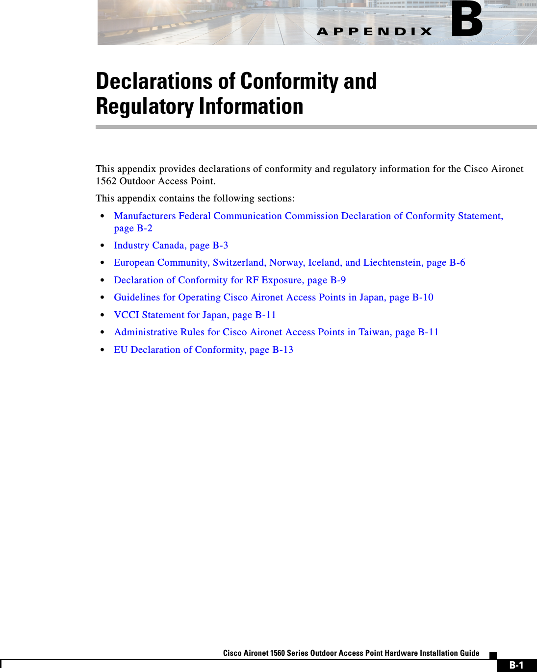
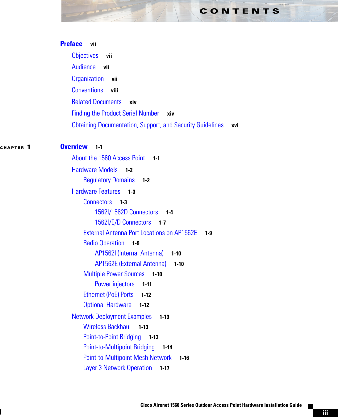
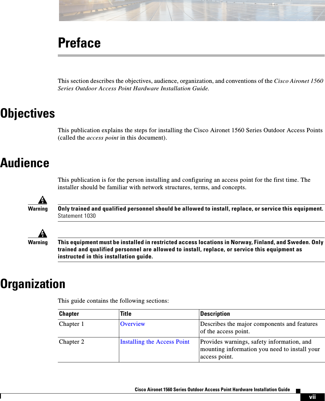
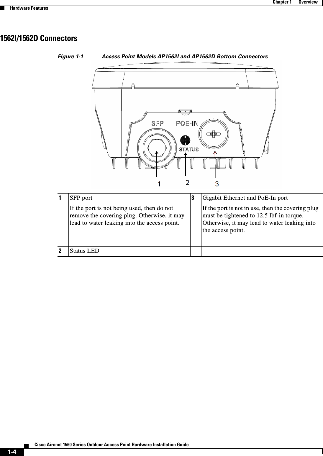
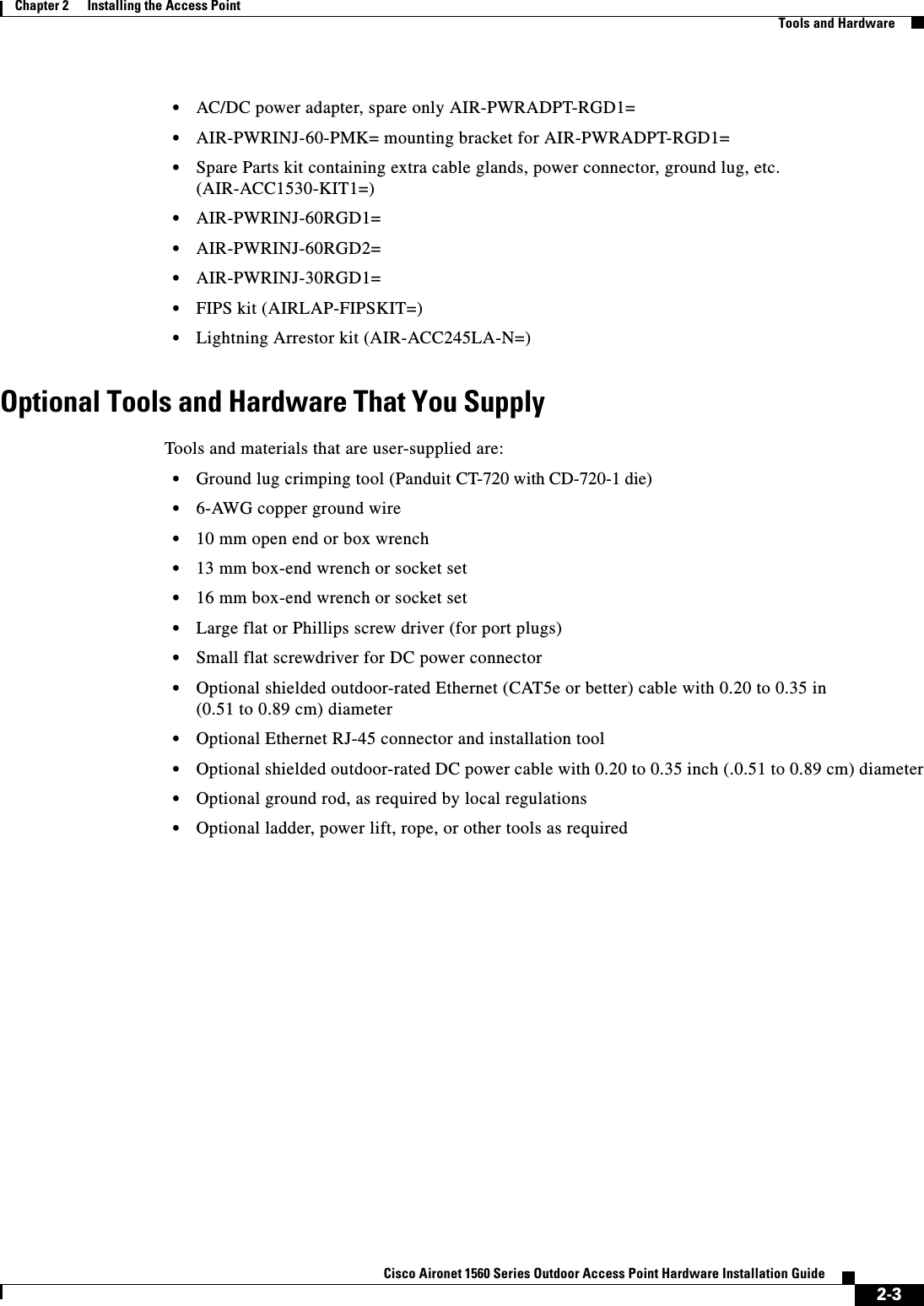
![2-24Cisco Aironet 1560 Series Outdoor Access Point Hardware Installation Guide Chapter 2 Installing the Access PointMounting the Access PointFigure 2-11 Pivoting Mounting Kit Dimensions Table 2-5 Materials for Mounting on Wall with Pivoting Mounting Kit3520001003.94281.10562.20 2x M8 THRU 4X 6.5MM THRU 17.10.67SLOT LENGTH [4.0].16SLOT WIDTHMaterials Required for mounting AP on a vertical wall with pivoting mounting kitIn KitGround lug and screws (provided with access point) YesPivoting mount kit and hardware Yes(8) M6 x 12-mm Hex-head Bolts YesAdapter bracket for option horizontal mount YesTwo stainless steel band clamps (adjustable 2"-5", 51 mm - 127 mm)YesTwo stainless steel band clamps (adjustable 5"-8", 127 mm - 203 mm)YesCrimping tool for ground lug, Panduit CT-720 with CD-720-1 die (http://www.panduit.com)NoFour wall mounting screws (6mm max) NoFour wall anchors (specified for all material) NoDrill bit for wall anchors NoElectric drill and standard screwdriver No#6 AWG ground wire NoShielded outdoor-rated Ethernet (CAT5e or better) cable NoGrounding block NoGrounding rod No](https://usermanual.wiki/Cisco-Systems/102104/User-Guide-3170826-Page-58.png)