Cisco Systems 102104 Cisco Aironet 802.11ac Dual Band Outdoor Access Points User Manual 1560hig
Cisco Systems Inc Cisco Aironet 802.11ac Dual Band Outdoor Access Points 1560hig
1560hig_edit

Cisco Systems, Inc.
www.cisco.com
Cisco has more than 200 offices worldwide.
Addresses, phone numbers, and fax numbers
are listed on the Cisco website at
www.cisco.com/go/offices.
Cisco Aironet 1560 Series Outdoor Access
Point Hardware Installation Guide
First Published: August 30, 2016
Text Part Number:
THE SPECIFICATIONS AND INFORMATION REGARDING THE PRODUCTS IN THIS MANUAL ARE SUBJECT TO CHANGE WITHOUT NOTICE. ALL
STATEMENTS, INFORMATION, AND RECOMMENDATIONS IN THIS MANUAL ARE BELIEVED TO BE ACCURATE BUT ARE PRESENTED WITHOUT
WARRANTY OF ANY KIND, EXPRESS OR IMPLIED. USERS MUST TAKE FULL RESPONSIBILITY FOR THEIR APPLICATION OF ANY PRODUCTS.
THE SOFTWARE LICENSE AND LIMITED WARRANTY FOR THE ACCOMPANYING PRODUCT ARE SET FORTH IN THE INFORMATION PACKET THAT
SHIPPED WITH THE PRODUCT AND ARE INCORPORATED HEREIN BY THIS REFERENCE. IF YOU ARE UNABLE TO LOCATE THE SOFTWARE LICENSE
OR LIMITED WARRANTY, CONTACT YOUR CISCO REPRESENTATIVE FOR A COPY.
The following information is for FCC compliance of Class A devices: This equipment has been tested and found to comply with the limits for a Class A digital device, pursuant
to part 15 of the FCC rules. These limits are designed to provide reasonable protection against harmful interference when the equipment is operated in a commercial
environment. This equipment generates, uses, and can radiate radio-frequency energy and, if not installed and used in accordance with the instruction manual, may cause
harmful interference to radio communications. Operation of this equipment in a residential area is likely to cause harmful interference, in which case users will be required
to correct the interference at their own expense.
The following information is for FCC compliance of Class B devices: This equipment has been tested and found to comply with the limits for a Class B digital device, pursuant
to part 15 of the FCC rules. These limits are designed to provide reasonable protection against harmful interference in a residential installation. This equipment generates,
uses and can radiate radio frequency energy and, if not installed and used in accordance with the instructions, may cause harmful interference to radio communications.
However, there is no guarantee that interference will not occur in a particular installation. If the equipment causes interference to radio or television reception, which can be
determined by turning the equipment off and on, users are encouraged to try to correct the interference by using one or more of the following measures:
• Reorient or relocate the receiving antenna.
• Increase the separation between the equipment and receiver.
• Connect the equipment into an outlet on a circuit different from that to which the receiver is connected.
• Consult the dealer or an experienced radio/TV technician for help.
Modifications to this product not authorized by Cisco could void the FCC approval and negate your authority to operate the product.
The Cisco implementation of TCP header compression is an adaptation of a program developed by the University of California, Berkeley (UCB) as part of UCB’s public
domain version of the UNIX operating system. All rights reserved. Copyright © 1981, Regents of the University of California.
NOTWITHSTANDING ANY OTHER WARRANTY HEREIN, ALL DOCUMENT FILES AND SOFTWARE OF THESE SUPPLIERS ARE PROVIDED “AS IS” WITH
ALL FAULTS. CISCO AND THE ABOVE-NAMED SUPPLIERS DISCLAIM ALL WARRANTIES, EXPRESSED OR IMPLIED, INCLUDING, WITHOUT
LIMITATION, THOSE OF MERCHANTABILITY, FITNESS FOR A PARTICULAR PURPOSE AND NONINFRINGEMENT OR ARISING FROM A COURSE OF
DEALING, USAGE, OR TRADE PRACTICE.
IN NO EVENT SHALL CISCO OR ITS SUPPLIERS BE LIABLE FOR ANY INDIRECT, SPECIAL, CONSEQUENTIAL, OR INCIDENTAL DAMAGES, INCLUDING,
WITHOUT LIMITATION, LOST PROFITS OR LOSS OR DAMAGE TO DATA ARISING OUT OF THE USE OR INABILITY TO USE THIS MANUAL, EVEN IF CISCO
OR ITS SUPPLIERS HAVE BEEN ADVISED OF THE POSSIBILITY OF SUCH DAMAGES.
Cisco and the Cisco logo are trademarks or registered trademarks of Cisco and/or its affiliates in the U.S. and other countries. To view a list of Cisco trademarks, go to this
URL: www.cisco.com/go/trademarks. Third-party trademarks mentioned are the property of their respective owners. The use of the word partner does not imply a partnership
relationship between Cisco and any other company. (1110R)
Any Internet Protocol (IP) addresses and phone numbers used in this document are not intended to be actual addresses and phone numbers. Any examples, command display
output, network topology diagrams, and other figures included in the document are shown for illustrative purposes only. Any use of actual IP addresses or phone numbers in
illustrative content is unintentional and coincidental.
© 2016 Cisco Systems, Inc. All rights reserved.

iii
Cisco Aironet 1560 Series Outdoor Access Point Hardware Installation Guide
CONTENTS
Preface vii
Objectives vii
Audience vii
Organization vii
Conventions viii
Related Documents xiv
Finding the Product Serial Number xiv
Obtaining Documentation, Support, and Security Guidelines xvi
CHAPTER
1Overview 1-1
About the 1560 Access Point 1-1
Hardware Models 1-2
Regulatory Domains 1-2
Hardware Features 1-3
Connectors 1-3
1562I/1562D Connectors 1-4
1562I/E/D Connectors 1-7
External Antenna Port Locations on AP1562E 1-9
Radio Operation 1-9
AP1562I (Internal Antenna) 1-10
AP1562E (External Antenna) 1-10
Multiple Power Sources 1-10
Power injectors 1-11
Ethernet (PoE) Ports 1-12
Optional Hardware 1-12
Network Deployment Examples 1-13
Wireless Backhaul 1-13
Point-to-Point Bridging 1-13
Point-to-Multipoint Bridging 1-14
Point-to-Multipoint Mesh Network 1-16
Layer 3 Network Operation 1-17

Contents
iv
Cisco Aironet 1560 Series Outdoor Access Point Hardware Installation Guide
CHAPTER
2Installing the Access Point 2-1
Unpacking the Access Point 2-2
Package Contents 2-2
Tools and Hardware 2-2
Optional Tools and Hardware 2-2
Optional Tools and Hardware That You Supply 2-3
Warnings 2-3
Safety Information 2-4
FCC Safety Compliance Statement 2-4
Safety Precautions 2-4
Avoiding Damage to Radios in a Testing Environment 2-6
Installation Guidelines 2-7
Site Surveys 2-7
Before Beginning the Installation 2-8
Becoming Familiar with Access Point Installation Components 2-8
Mounting the Access Point 2-11
AP Mounting Options 2-11
Access Point Mounting Orientation 2-11
Wall Mounting the Access Point with AIR-ACC1530-PMK1= Mounting Kit 2-12
Wall Mounting the Access Point with AIR-ACC1560-PMK1= Mounting Kit 2-15
Pole Mounting the Access Point with the AIR-ACC1530-PMK2= Kit 2-18
Pole Mounting the Access Point with the AIR-ACC1560-PMK2= Kit 2-20
Wall Mounting the Access Point with the Pivoting Mounting Kit 2-22
Pole Mounting the Access Point with the Pivoting Mounting Kit 2-25
Horizontally Mounting the Access Point with Optional Horizontal Mount Plate 2-28
Installing AP Cover or Solar Shield (AIR-ACC1560-CVR=) 2-32
Installing Antennas 2-33
Non-Cisco Antennas 2-33
Safety Precautions when Installing Antennas 2-34
Antenna Configurations 2-34
Integrated Antenna Option 2-34
External Antenna Mounting Configurations 2-35
Using a Mounting Bracket for External Directional Antennas 2-43
Antenna N-Type Connector Locations 2-44
Installing a Lightning Arrestor 2-44
Installation Considerations 2-44
Installation Notes 2-45
Installing the Lightning Arrestor Outdoors 2-45

Contents
v
Cisco Aironet 1560 Series Outdoor Access Point Hardware Installation Guide
Cable for the Lightning Arrestor 2-46
Grounding the Access Point 2-46
Powering the Access Point 2-47
Connecting a 1560 Series Power Injector 2-48
Connecting an Ethernet Cable to the Access Point 2-49
Connecting a DC Power Cable to the Access Point 2-52
Connecting Streetlight AC Power 2-56
Connecting a Fiber-optic Cable to the AP 2-58
Configuring the Access Point 2-62
What to Do Next 2-63
CHAPTER
3Troubleshooting 3-1
Guidelines for Using the Access Points 3-2
Important Notes 3-2
Convergence Delays 3-2
Bridge Loop 3-3
Controller DHCP Server 3-3
MAP Data Traffic 3-3
Controller MAC Filter List 3-3
Using DHCP Option 43 3-3
Monitoring the Access Point LEDs 3-4
Verifying Controller Association 3-6
Changing the Bridge Group Name 3-7
Accessing the Console Port and the Reset Button 3-7
Resetting the Access Point 3-9
APPENDIX
ATranslated Safety Warnings A-1
APPENDIX
BDeclarations of Conformity and Regulatory Information B-1
Manufacturers Federal Communication Commission Declaration of Conformity Statement B-2
Requirements of operator to register the RLAN device operating Outdoors in the 5150 -5250 MHz
band and addressing possible interference issues in this band B-3
Industry Canada B-3
Canadian Compliance Statement B-3
Declaration of Conformity for RF Exposure B-5
European Community, Switzerland, Norway, Iceland, and Liechtenstein B-6
Declaration of Conformity with regard to the R&TTE Directive 1999/5/EC & Medical Directive
93/42/EEC B-6

Contents
vi
Cisco Aironet 1560 Series Outdoor Access Point Hardware Installation Guide
Declaration of Conformity for RF Exposure B-9
United States B-9
Canada B-9
European Union B-9
Australia B-9
Guidelines for Operating Cisco Aironet Access Points in Japan B-10
Japanese Translation B-10
English Translation B-10
VCCI Statement for Japan B-11
Administrative Rules for Cisco Aironet Access Points in Taiwan B-11
Chinese Translation B-11
English Translation B-12
Chinese Translation B-12
English Translation B-12
Statement 371—Power Cable and AC Adapter B-13
English Translation B-13
EU Declaration of Conformity B-13
Operation of Cisco Aironet Access Points in Brazil B-13
Access Point Models B-13
Regulatory Information B-14
Portuguese Translation B-14
English Translation B-14
APPENDIX
CChannels and Power Levels C-1
APPENDIX
DAccess Point Data Sheet D-1
APPENDIX
EAccess Point Pinouts E-1
APPENDIX
FConfiguring DHCP Option 43 F-1
vii
Cisco Aironet 1560 Series Outdoor Access Point Hardware Installation Guide
Preface
This section describes the objectives, audience, organization, and conventions of the Cisco Aironet 1560
Series Outdoor Access Point Hardware Installation Guide.
Objectives
This publication explains the steps for installing the Cisco Aironet 1560 Series Outdoor Access Points
(called the access point in this document).
Audience
This publication is for the person installing and configuring an access point for the first time. The
installer should be familiar with network structures, terms, and concepts.
Warning
Only trained and qualified personnel should be allowed to install, replace, or service this equipment.
Statement 1030
Warning
This equipment must be installed in restricted access locations in Norway, Finland, and Sweden. Only
trained and qualified personnel are allowed to install, replace, or service this equipment as
instructed in this installation guide.
Organization
This guide contains the following sections:
Chapter Title Description
Chapter 1 Overview Describes the major components and features
of the access point.
Chapter 2 Installing the Access Point Provides warnings, safety information, and
mounting information you need to install your
access point.

viii
Cisco Aironet 1560 Series Outdoor Access Point Hardware Installation Guide
Conventions
This publication uses the following conventions:
Notes use the following conventions:
Chapter 3 Troubleshooting Provides basic troubleshooting procedures for
the access point.
Appendix A Translated Safety Warnings Indicates how to access the document that
provides translations of the safety warnings
that appear in this publication.
Appendix B Declarations of Conformity
and Regulatory Information
Describes the regulatory conventions to which
the access point conforms and provides
guidelines for operating access points in Japan.
Appendix C Channels and Power Levels Indicates how to access the document that lists
the access point radio channels and the
maximum power levels supported by the world
regulatory domains.
Appendix D Access Point Data Sheet Lists technical specifications for the access
point.
Appendix E Access Point Pinouts Describes the connector pinouts for the access
point.
Appendix F Configuring DHCP Option
43
Describes the procedure to configure DHCP
Option 43.
Chapter Title Description
Convention Description
boldface font Commands, command options, and keywords are
in boldface.
italic font Arguments for which you supply values are in
italics.
[ ] Elements in square brackets are optional.
screen font Terminal sessions and information the system
displays are in screen font.
boldface screen font Information you must enter is in boldface screen
font.
italic screen font Arguments for which you supply values are in
italic screen font.
^ The symbol ^ represents the key labeled Control.
For example, the key combination ^D in a screen
display means hold down the Control key while
you press the D key.
< > Nonprinting characters, such as passwords, are in
angle brackets.

ix
Cisco Aironet 1560 Series Outdoor Access Point Hardware Installation Guide
Note Means reader take note. Notes contain helpful suggestions or references to materials not contained in
this manual.
Cautions use the following conventions:
Caution Means reader be careful. In this situation, you might do something that could result in equipment
damage or loss of data.
Warnings use the following conventions:
Warning
IMPORTANT SAFETY INSTRUCTIONS
This warning symbol means danger. You are in a situation that could cause bodily injury. Before you
work on any equipment, be aware of the hazards involved with electrical circuitry and be familiar
with standard practices for preventing accidents. Use the statement number provided at the end of
each warning to locate its translation in the translated safety warnings that accompanied this
device.
Statement 1071
SAVE THESE INSTRUCTIONS
Waarschuwing
BELANGRIJKE VEILIGHEIDSINSTRUCTIES
Dit waarschuwingssymbool betekent gevaar. U verkeert in een situatie die lichamelijk letsel kan
veroorzaken. Voordat u aan enige apparatuur gaat werken, dient u zich bewust te zijn van de bij
elektrische schakelingen betrokken risico's en dient u op de hoogte te zijn van de standaard
praktijken om ongelukken te voorkomen. Gebruik het nummer van de verklaring onderaan de
waarschuwing als u een vertaling van de waarschuwing die bij het apparaat wordt geleverd, wilt
raadplegen.
BEWAAR DEZE INSTRUCTIES
Varoitus
TÄRKEITÄ TURVALLISUUSOHJEITA
Tämä varoitusmerkki merkitsee vaaraa. Tilanne voi aiheuttaa ruumiillisia vammoja. Ennen kuin
käsittelet laitteistoa, huomioi sähköpiirien käsittelemiseen liittyvät riskit ja tutustu
onnettomuuksien yleisiin ehkäisytapoihin. Turvallisuusvaroitusten käännökset löytyvät laitteen
mukana toimitettujen käännettyjen turvallisuusvaroitusten joukosta varoitusten lopussa näkyvien
lausuntonumeroiden avulla.
SÄILYTÄ NÄMÄ OHJEET

x
Cisco Aironet 1560 Series Outdoor Access Point Hardware Installation Guide
Attention
IMPORTANTES INFORMATIONS DE SÉCURITÉ
Ce symbole d'avertissement indique un danger. Vous vous trouvez dans une situation pouvant
entraîner des blessures ou des dommages corporels. Avant de travailler sur un équipement, soyez
conscient des dangers liés aux circuits électriques et familiarisez-vous avec les procédures
couramment utilisées pour éviter les accidents. Pour prendre connaissance des traductions des
avertissements figurant dans les consignes de sécurité traduites qui accompagnent cet appareil,
référez-vous au numéro de l'instruction situé à la fin de chaque avertissement.
CONSERVEZ CES INFORMATIONS
Warnung
WICHTIGE SICHERHEITSHINWEISE
Dieses Warnsymbol bedeutet Gefahr. Sie befinden sich in einer Situation, die zu Verletzungen führen
kann. Machen Sie sich vor der Arbeit mit Geräten mit den Gefahren elektrischer Schaltungen und
den üblichen Verfahren zur Vorbeugung vor Unfällen vertraut. Suchen Sie mit der am Ende jeder
Warnung angegebenen Anweisungsnummer nach der jeweiligen Übersetzung in den übersetzten
Sicherheitshinweisen, die zusammen mit diesem Gerät ausgeliefert wurden.
BEWAHREN SIE DIESE HINWEISE GUT AUF.
Avvertenza
IMPORTANTI ISTRUZIONI SULLA SICUREZZA
Questo simbolo di avvertenza indica un pericolo. La situazione potrebbe causare infortuni alle
persone. Prima di intervenire su qualsiasi apparecchiatura, occorre essere al corrente dei pericoli
relativi ai circuiti elettrici e conoscere le procedure standard per la prevenzione di incidenti.
Utilizzare il numero di istruzione presente alla fine di ciascuna avvertenza per individuare le
traduzioni delle avvertenze riportate in questo documento.
CONSERVARE QUESTE ISTRUZIONI
Advarsel
VIKTIGE SIKKERHETSINSTRUKSJONER
Dette advarselssymbolet betyr fare. Du er i en situasjon som kan føre til skade på person. Før du
begynner å arbeide med noe av utstyret, må du være oppmerksom på farene forbundet med
elektriske kretser, og kjenne til standardprosedyrer for å forhindre ulykker. Bruk nummeret i slutten
av hver advarsel for å finne oversettelsen i de oversatte sikkerhetsadvarslene som fulgte med denne
enheten.
TA VARE PÅ DISSE INSTRUKSJONENE
Aviso
INSTRUÇÕES IMPORTANTES DE SEGURANÇA
Este símbolo de aviso significa perigo. Você está em uma situação que poderá ser causadora de
lesões corporais. Antes de iniciar a utilização de qualquer equipamento, tenha conhecimento dos
perigos envolvidos no manuseio de circuitos elétricos e familiarize-se com as práticas habituais de
prevenção de acidentes. Utilize o número da instrução fornecido ao final de cada aviso para
localizar sua tradução nos avisos de segurança traduzidos que acompanham este dispositivo.
GUARDE ESTAS INSTRUÇÕES
xi
Cisco Aironet 1560 Series Outdoor Access Point Hardware Installation Guide
¡Advertencia!
INSTRUCCIONES IMPORTANTES DE SEGURIDAD
Este símbolo de aviso indica peligro. Existe riesgo para su integridad física. Antes de manipular
cualquier equipo, considere los riesgos de la corriente eléctrica y familiarícese con los
procedimientos estándar de prevención de accidentes. Al final de cada advertencia encontrará el
número que le ayudará a encontrar el texto traducido en el apartado de traducciones que acompaña
a este dispositivo.
GUARDE ESTAS INSTRUCCIONES
Varning!
VIKTIGA SÄKERHETSANVISNINGAR
Denna varningssignal signalerar fara. Du befinner dig i en situation som kan leda till personskada.
Innan du utför arbete på någon utrustning måste du vara medveten om farorna med elkretsar och
känna till vanliga förfaranden för att förebygga olyckor. Använd det nummer som finns i slutet av
varje varning för att hitta dess översättning i de översatta säkerhetsvarningar som medföljer denna
anordning.
SPARA DESSA ANVISNINGAR
Figyelem
xii
Cisco Aironet 1560 Series Outdoor Access Point Hardware Installation Guide
Aviso
INSTRUÇÕES IMPORTANTES DE SEGURANÇA
Este símbolo de aviso significa perigo. Você se encontra em uma situação em que há risco de lesões
corporais. Antes de trabalhar com qualquer equipamento, esteja ciente dos riscos que envolvem os
circuitos elétricos e familiarize-se com as práticas padrão de prevenção de acidentes. Use o
número da declaração fornecido ao final de cada aviso para localizar sua tradução nos avisos de
segurança traduzidos que acompanham o dispositivo.
GUARDE ESTAS INSTRUÇÕES
Advarsel
VIGTIGE SIKKERHEDSANVISNINGER
Dette advarselssymbol betyder fare. Du befinder dig i en situation med risiko for
legemesbeskadigelse. Før du begynder arbejde på udstyr, skal du være opmærksom på de
involverede risici, der er ved elektriske kredsløb, og du skal sætte dig ind i standardprocedurer til
undgåelse af ulykker. Brug erklæringsnummeret efter hver advarsel for at finde oversættelsen i de
oversatte advarsler, der fulgte med denne enhed.
GEM DISSE ANVISNINGER
xiii
Cisco Aironet 1560 Series Outdoor Access Point Hardware Installation Guide
xiv
Cisco Aironet 1560 Series Outdoor Access Point Hardware Installation Guide
Related Documents
These documents provide complete information about the access point:
•Release Notes for Cisco Wireless LAN Controllers and Lightweight Access Points
•Quick Start Guide: Cisco Aironet 1560 Series Outdoor Access Points
•Cisco Wireless LAN Controller Configuration Guide
Click this link to browse to the Cisco Wireless documentation home page:
http://www.cisco.com/en/US/products/hw/wireless/index.html
To browse to the access point documentation, click Cisco Aironet 1560 Series listed under “Outdoor
Wireless.” The documentation can be accessed from the Support box.
To browse to the Cisco Wireless LAN Controller documentation, click Standalone Controllers listed
under “Wireless LAN Controllers.” The documentation can be accessed from the Support box.
Finding the Product Serial Number
The access point serial number is on the side of the access point (refer to Figure 1).
xv
Cisco Aironet 1560 Series Outdoor Access Point Hardware Installation Guide
Figure 1 Location of Serial Number Label on the Left of the AP
The access point serial number label contains the following information:
•Model number, such as AIR-AP1562E-x-K9.
•Serial number, such as WCN0636279B (11 alphanumeric digits).
•Access point MAC address, for example 68BDABF54600 (12 hexadecimal digits). It is located
under the serial number.
You need your product serial number when requesting support from the Cisco Technical Assistance
Center.

xvi
Cisco Aironet 1560 Series Outdoor Access Point Hardware Installation Guide
Obtaining Documentation, Support, and Security Guidelines
For information on obtaining documentation and support, providing documentation feedback, security
guidelines, and recommended aliases and general Cisco documents, see the monthly What’s New in
Cisco Product Documentation, which also lists all new and revised Cisco technical documentation, at:
http://www.cisco.com/en/US/docs/general/whatsnew/whatsnew.html
To view all new wireless documentation, click on Wireless.

CHAPTER
1-1
Cisco Aironet 1560 Series Outdoor Access Point Hardware Installation Guide
1
Overview
The Cisco Aironet 1560 Series Outdoor Access Point (hereafter called the access point or AP) is a
wireless outdoor access point which is designed for use in a variety of network configurations. The
access point supports wireless client access, point-to-point bridging, point-to-multipoint bridging, and
point-to-multipoint mesh wireless connectivity.
About the 1560 Access Point
The 1560 access point supports two radios (2.4-GHz and 5-GHz) and provides client access using the
unlicensed RF Wi-Fi spectrum. The radios have 802.11ac Wave 2 capability.
The 5 GHz radios have 802.11ac Wave 2 capability. The 2.4 GHz or 5 GHz radio can be used for client
access or can be used for both client access and backhaul traffic. Depending on the model, the access
point can support up to 1.3 Gbps data rates. For more information, see Appendix D, “Access Point Data
Sheet”.
The access point is a standalone unit that can be wall, pole or tower mounted. The access point can also
operate as a relay node for other access points not directly connected to a wired network. Intelligent
wireless routing is provided by the patented Adaptive Wireless Path Protocol (AWPP). This enables each
access point to identify its neighbors and intelligently choose the optimal path to the wired network by
calculating the cost of each path in terms of signal strength and the number of hops required to get to a
controller.
The access point can be configured, monitored, and operated through a Cisco wireless LAN controller
(hereafter called a controller) as described in the Cisco Wireless LAN Controller Configuration Guide.
The Cisco Wireless Mesh Access Points, Design and Deployment Guide, describes how to plan and
initially configure the Cisco mesh network, which supports wireless point-to-point, point-to-multipoint,
and mesh deployments. The controllers use a browser-based management system, a command-line
interface (CLI), or the Cisco Prime Infrastructure (PI) network management system to manage the
controller and the associated access points. The access point supports hardware-based advanced
encryption standard (AES) encryption between wireless nodes to provide end-to-end security. The
access point can also be deployed in an autonomous mode and be configured via the CLI.
This chapter provides information on the following topics:
•Hardware Models, page 1-2
•Hardware Features, page 1-3
•Network Deployment Examples, page 1-13

1-2
Cisco Aironet 1560 Series Outdoor Access Point Hardware Installation Guide
Chapter 1 Overview
Hardware Models
Hardware Models
The model numbers (or part numbers) and configuration for the Cisco Aironet 1560 Outdoor Access
Points are described in Table 1-1.
For a detailed description of the declarations of conformity and regulatory information for the 1560
access points refer to Appendix B, “Declarations of Conformity and Regulatory Information.”
Regulatory Domains
The “-x” in the 1560 model numbers represent the domain. For example, in AIR-AP1562I-x-K9, the -x
represents a regulatory domain for a specific country. For specific regulatory domains supported by each
1560 access point model, refer to the Wireless LAN Compliance Status at the following URL:
http://www.cisco.com/go/aironet/compliance
Table 1-1 1560 Access Point Model Numbers and Descriptions
Model (or part number) Configuration
AIR-AP1562I-x-K9 The AP 1562I has integrated omni antennas and
contains a 2.4 GHz and 5 GHz radio with an
option to configure in centralized, Flexconnect, or
mesh mode.
This is a stand alone unit that can be wall, pole or
tower mounted. It can also operate as a relay node
for other access points that are not directly
connected to a wired network.
AIR-AP1562E-x-K9 The AP 1562E has 4 external antenna ports and
contains a 2.4 GHz and 5 GHz radio with an
option to configure in centralized, Flexconnect, or
mesh mode.
This is a stand alone unit that can be wall, pole or
tower mounted. It can also operate as a relay node
for other access points that are not directly
connected to a wired network.
AIR-AP1562D-x-K9 The AP 1562 has integrated directional antennas
and contains a 2.4 GHz and 5 GHz radio with an
option to configure in centralized, Flexconnect, or
mesh mode.
This is a stand alone unit that can be wall, pole or
tower mounted. It can also operate as a relay node
for other access points that are not directly
connected to a wired network.

1-3
Cisco Aironet 1560 Series Outdoor Access Point Hardware Installation Guide
Chapter 1 Overview
Hardware Features
Hardware Features
This section describes the hardware features of the 1560 access point models. The following hardware
features are described in this section:
•Connectors, page 1-3
•External Antenna Port Locations on AP1562E, page 1-9
•Multiple Power Sources, page 1-10
•Ethernet (PoE) Ports, page 1-12
•Optional Hardware, page 1-12
Connectors
Figure 1-4 and Figure 1-5 show the access point connectors for all models. Figure 1-1 shows the bottom
connectors for internal antenna model, and Figure 1-2 and Figure 1-3 show the external antenna Type-N
connectors.
Note The illustrations in this document show all available connections for the access point. Unused
connections are capped with a connector plug to ensure the watertight integrity of the access point.
Liquid-tight adapters are provided for connector openings, which can be installed before or after
deploying the access point.
1-4
Cisco Aironet 1560 Series Outdoor Access Point Hardware Installation Guide
Chapter 1 Overview
Hardware Features
1562I/1562D Connectors
Figure 1-1 Access Point Models AP1562I and AP1562D Bottom Connectors
1SFP port
If the port is not being used, then do not
remove the covering plug. Otherwise, it may
lead to water leaking into the access point.
3Gigabit Ethernet and PoE-In port
If the port is not in use, then the covering plug
must be tightened to 12.5 lbf-in torque.
Otherwise, it may lead to water leaking into
the access point.
2Status LED
1-5
Cisco Aironet 1560 Series Outdoor Access Point Hardware Installation Guide
Chapter 1 Overview
Hardware Features
Figure 1-2 Access Point Model AP1562E Bottom Connectors
1Antenna 1 port 4Status LED
2Antenna 2 port 5Gigabit Ethernet and PoE-In port
If the port is not in use, then the covering plug
must be tightened to 12.5 lbf-in torque.
Otherwise, it may lead to water leaking into
the access point.
3SFP port
If the port is not being used, then do not
remove the covering plug. Otherwise, it may
lead to water leaking into the access point.
1-6
Cisco Aironet 1560 Series Outdoor Access Point Hardware Installation Guide
Chapter 1 Overview
Hardware Features
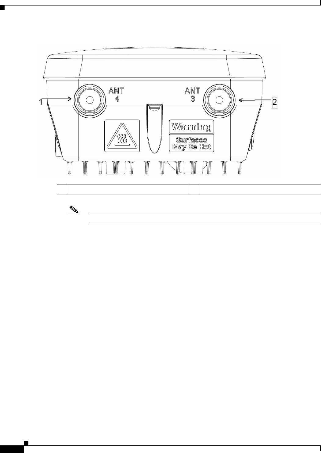
Figure 1-3 Access Point Model AP1562E Top Connectors
Note The AP1562I and AP1562D models do not have any top connectors.
1Antenna port 4 2Antenna port 3
1-7
Cisco Aironet 1560 Series Outdoor Access Point Hardware Installation Guide
Chapter 1 Overview
Hardware Features
1562I/E/D Connectors
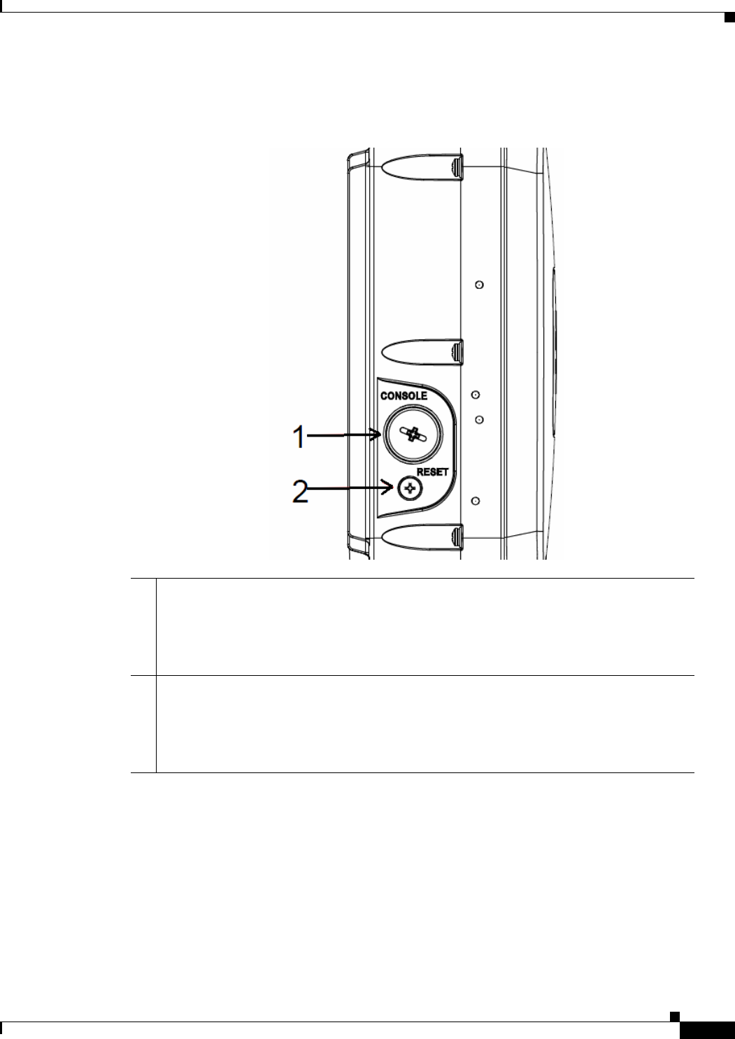
Figure 1-4 Right Side Connectors on all models
1Console port.
The console port is under a covering plug. Inspect the seal of the plug and properly tighten
it at the time of installation, and also every time the plug is removed and replaced. Tighten
the plug to 12.5 lbf-in. If you do not tighten the plug properly, it will not meet IP67 criteria,
and may lead to water leaking into the unit.
2Reset button.
The reset button is under covering screw. Properly tighten it at the time of installation, and
also every time the it is removed and replaced. Tighten the screw to 24 lbf-in. If you do not
tighten the screw properly, it will not meet IP67 criteria, and may lead to water leaking into
the unit.
1-8
Cisco Aironet 1560 Series Outdoor Access Point Hardware Installation Guide
Chapter 1 Overview
Hardware Features
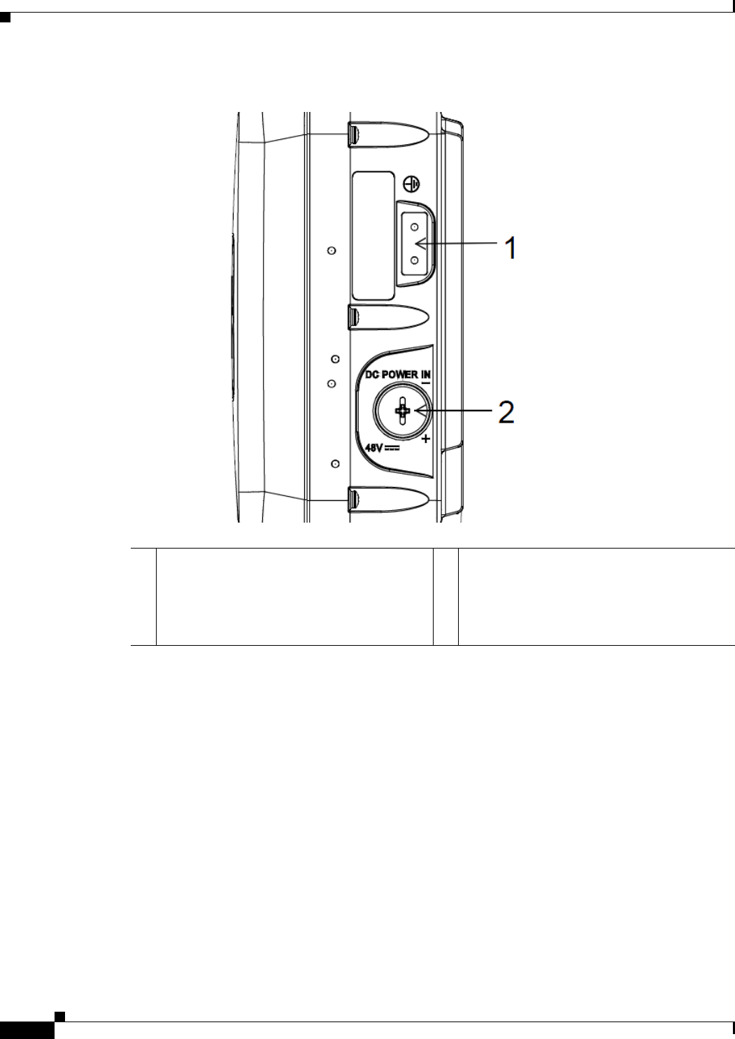
Figure 1-5 Left Side Connectors on All Models
1Ground Pad. 2DC Power-In (covered).
If the port is not in use, then the covering plug
must be tightened to 12.5 lbf-in torque.
Otherwise, it may lead to water leaking into
the access point.
1-9
Cisco Aironet 1560 Series Outdoor Access Point Hardware Installation Guide
Chapter 1 Overview
Hardware Features
External Antenna Port Locations on AP1562E
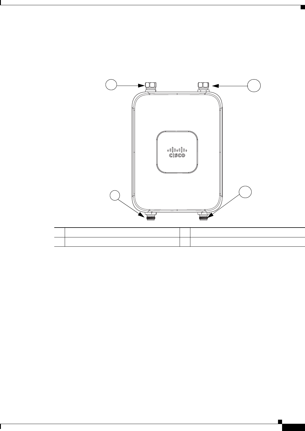
Figure 1-6 shows the antenna port locations for model AP1562E. The ports used depend on the optional
antennas ordered.
Figure 1-6 External Antenna Port Locations for Access Point Model AP1562E
AP1562I (Internal Antenna)
The 1562I access point 802.11b/g/n radio is used primarily for local access and its 802.11a/n/ac radio
for wireless backhaul in the Mesh.
The 2 GHz b/g/n radio operates in 2.4 GHz ISM band. It supports channels 1-11 in the US, 1-13 in
Europe, and 1-13 in Japan. It has 3 transmitters with a maximum total output power of 29 dBm for
802.11b/g/n operation. Output power is configurable for 8 levels in 3 dB steps. It has three receivers that
enable maximum-ratio combining (MRC).
The 5 GHz a/n radio operates in the UNII-1 band (5.15-5.25 GHz), UNII-2 band (5.25 - 5.35 GHz),
UNII-2 Extended/ETSI band (5.47 - 5.725 GHz), and the upper ISM band (5.725 - 5.850 GHz). It has
two transmitters with a maximum total output power of 27 dBm depending on the regulatory domain.
The total maximum output power for the upper ISM band is 27 dBm for A-domain. Tx power settings
will change depending on the regulatory domain. Output power is configurable in 3 dB steps. Its three
receivers enable maximum-ratio combining (MRC).
The 1562I access point is equipped with three integrated dual-band antennas with 3 dBi gain at 2 GHz
and 5 dBi gain at 5 GHz.
351321
4
2
3
1
1Antenna port 1 – Type N connector 2Antenna port 2- Type N connector
3Antenna port 3– Type N connector (with cap) 4Antenna port 4- Type N connector (with cap)

1-10
Cisco Aironet 1560 Series Outdoor Access Point Hardware Installation Guide
Chapter 1 Overview
Hardware Features
AP1562E (External Antenna)
The 1562E access point is equipped with four N-type RF connectors. The 1562E can be configured via
software to support dual band or single band antennas. When configured for dual band antennas, antenna
ports 1 and 2 on the bottom of the unit (Figure 1-2) are used to support multiple input/multiple output
(MIMO) operation on both 2.4 and 5 GHz radios. When using the Cisco Aironet AIR-ANT2547V-N or
AIR-ANT2547VG-N omindirectional antennas, the antenna can be connected directly to the access
point (Figure 2-19). If the antennas are remotely located, an appropriate low loss RF cable should be
used.
Note Ensure that the antenna band mode is configured before the 1562E access point is installed.
When configured for single band antennas, antenna port 1 and antenna port 2 support MIMO operation
for the 2.4 GHz radio, and antenna ports 3 and 4 (Figure 1-3) support MIMO on the 5 GHz radio. See
the Cisco Wireless LAN Controller Configuration Guide for information on the software configuration.
Multiple Power Sources
The 1560 series access point supports these power sources:
•DC power – 42-57 VDC
•Power over Ethernet (PoE) – For more information, see “Powering the Access Point” section on
page 2-47.
Warning
Installation of the equipment must comply with local and national electrical codes.
Statement 1074
Warning
This equipment must be externally grounded using a customer-supplied ground wire before power is
applied. Contact the appropriate electrical inspection authority or an electrician if you are uncertain
that suitable grounding is available.
Statement 366
Warning
Do not work on the system or connect or disconnect cables during periods of lightning activity.
Statement 1001
Warning
Connect the unit only to DC power source that complies with the safety extra-low voltage (SELV)
requirements in IEC 60950 based safety standards.
Statement 1033
Warning
To reduce the risk of fire, use only No. 26 AWG or larger telecommunication line cord.
Statement 1023
Caution Several forms of PoE are supported. See Table Table 2-9 for the PoE options and their corresponding
modes of operation.

1-11
Cisco Aironet 1560 Series Outdoor Access Point Hardware Installation Guide
Chapter 1 Overview
Hardware Features
Caution Do not place the power injector in an unprotected outdoor environment because water could get into the
power injector and cause a short circuit and possible fire.
Caution When the access point is installed outdoors or in a wet or damp location, the AC branch circuit that is
powering the access point should be provided with ground fault protection (GFCI), as required by Article
210 of the National Electrical Code (NEC).
Power injectors
The 1560 series access points support the following power injectors:
•AIR-PWRINJ-60RGD1
•AIR-PWRINJ-60RGD2
•AIR-PWRINJ-30RGD1
Warning
To reduce the risk of fire, use only No. 26 AWG or larger telecommunications line cord.
Statement 1023
Caution When the access point is installed outdoors, or in a wet or damp location, the AC branch circuit that is
powering the access point should be provided with ground fault protection (GFCI), as required by Article
210 of the National Electrical Code (NEC).
Ethernet (PoE) Ports
The access point supports an Ethernet uplink port (PoE-In). The access point Ethernet uplink port uses
an RJ-45 connector (with weatherproofing) to link the access point to the 10BASE-T, 100BASE-T or
1000BASE-T network. The Ethernet cable is used to send and receive Ethernet data and to optionally
supply inline power from the power injector or a suitably powered switch port.
Tip The access point senses the Ethernet and power signals and automatically switches internal circuitry to
match the cable connections.
Warning
To reduce the risk of fire, use only No. 26 AWG or larger telecommunication line cord.
Statement 1023
The Ethernet cable must be a shielded outdoor rated Category 5e (CAT5e) or better cable. The access
point senses the Ethernet and power signals and automatically switches internal circuitry to match the
cable connections.
Optional Hardware
Depending on what you ordered, the following optional access point hardware may be part of your
shipment:

1-12
Cisco Aironet 1560 Series Outdoor Access Point Hardware Installation Guide
Chapter 1 Overview
Hardware Features
•External antennas, depending on which ones you purchased (See “AP1562E (External Antenna)”
section on page 1-10 for information on available external antennas.)
•Wall/Pole mount bracket AIR-ACC1530-PMK1(=)
•Wall/Pole mount bracket for AP and AC/DC power adapter AIR-ACC1560-PMK1(=)
•Wall/Pole mount bracket with tilt mechanism, spare only AIR-ACC1530-PMK2(=)
•Street light power tap (AIR-PWR-ST-LT-R3P=), works only with the AC/DC power adapter.
•Power injector AIR-PWRINJ6=
•AP cover / Solar Shield for 1560, spare only (AIR-ACC1560-CVR=)
•AC/DC power adapter, spare only AIR-PWRADPT-RGD1=
•AIR-PWRINJ-60-PMK= mounting bracket for AIR-PWRADPT-RGD1=
•Spare Parts kit containing extra cable glands, power connector, ground lug, etc.
(AIR-ACC1530-KIT1=)
•AIR-PWRINJ-60RGD1=
•AIR-PWRINJ-60RGD2=
•AIR-PWRINJ-30RGD1=
1-13
Cisco Aironet 1560 Series Outdoor Access Point Hardware Installation Guide
Chapter 1 Overview
Network Deployment Examples
Network Deployment Examples
The access point is a wireless device designed for wireless client access and point-to-point bridging,
point-to-multipoint bridging, and point-to-multipoint mesh wireless connectivity. The access point
provides 5-GHz backhaul capability to link with another access point to reach a wired network
connection or to provide repeater operations for other access points.
The access point plays two primary radio roles: a root access point (hereafter called a RAP) or a mesh
(non-root) access point (hereafter called a MAP), which is the default role of all access points. When the
access point has a fiber or wired Ethernet connection to the controller (through a switch), the radio role
is called a RAP. In order to be considered a RAP, the access point must be configured as a RAP. A RAP
is a parent node to any bridging or mesh network. A controller can support one or more RAPs, each one
parenting the same or different wireless networks. There can be more than one RAP for the same mesh
network for redundancy. RAPs and MAPs can support wireless clients on the 2.4-GHz and 5-GHz band.
Client access on 5-GHz is called universal client access.
When the access point does not have a wired Ethernet connection to the controller (through a switch),
the radio role is called a MAP. The MAPs have a wireless connection (through the backhaul interface)
to other MAPs and finally to a RAP which has an Ethernet connection through a switch to the controller.
MAPs may also have a wired Ethernet connection to a local LAN and serve as a bridge endpoint for that
LAN (using a point-to-point or point-to-multipoint bridge connection).
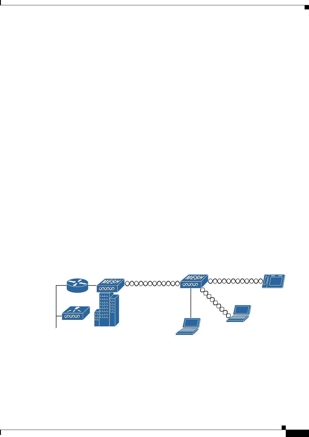
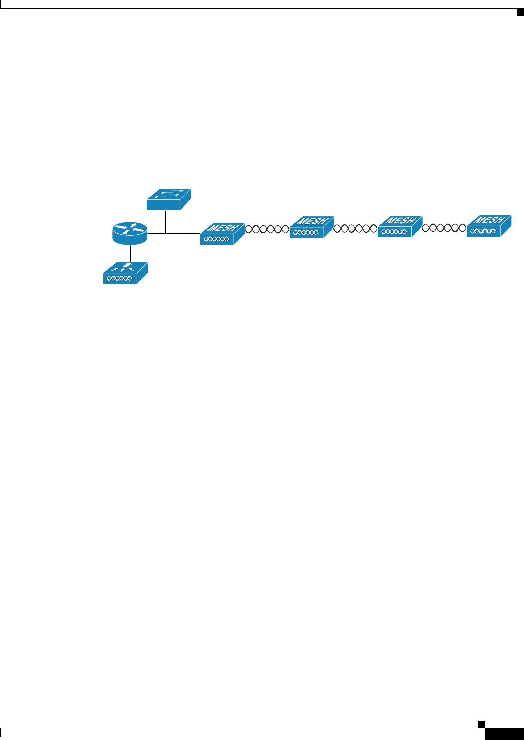
Wireless Backhaul
The access point supports wireless backhaul capability using the 5 GHz radio to bridge to another access
point to reach a wired network connection to a controller (see Figure 1-7). The access point connected
to the wired network is considered a RAP in this configuration. The remote access point is considered a
MAP and transfers wireless client traffic to the RAP for transfer to the wired network. Control And
Provisioning of Wireless Access Points (CAPWAP) control traffic is also transferred over this bridged
link.
Figure 1-7 Access Point Backhaul Example
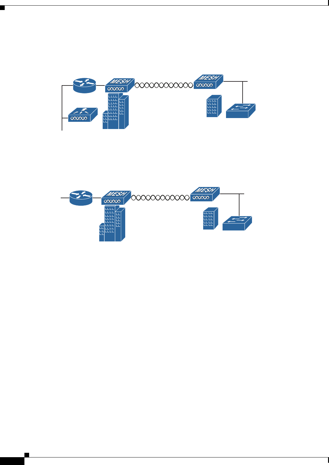
Point-to-Point Bridging
The access points can be used to extend a remote network by using the 5 GHz backhaul radio to bridge
the two network segments as shown in Figure 1-8. To support Ethernet bridging, you must enable
bridging on the controller for each access point. By default this capability is turned-off for all access
points.
255493
(5 GHz) (2.4 GHz and 5 GHz)
1-14
Cisco Aironet 1560 Series Outdoor Access Point Hardware Installation Guide
Chapter 1 Overview
Network Deployment Examples
Wireless client access is supported; however, if bridging between tall buildings, the 2.4-GHz wireless
coverage area may be limited and possibly not suitable for direct wireless client access.
Figure 1-8 Access Point Point-to-Point Bridging Example
The access points can also support point-to-point bridging under autonomous mode. In this autonomous
mode, the bridging can be done on the 2.4 or 5 GHz radio, but not both. In this mode, one access point
is designated as the root and the other end is designated as the non-root bridge.
Figure 1-9 Access Point Point-to-Point Bridging in Autonomous Mode
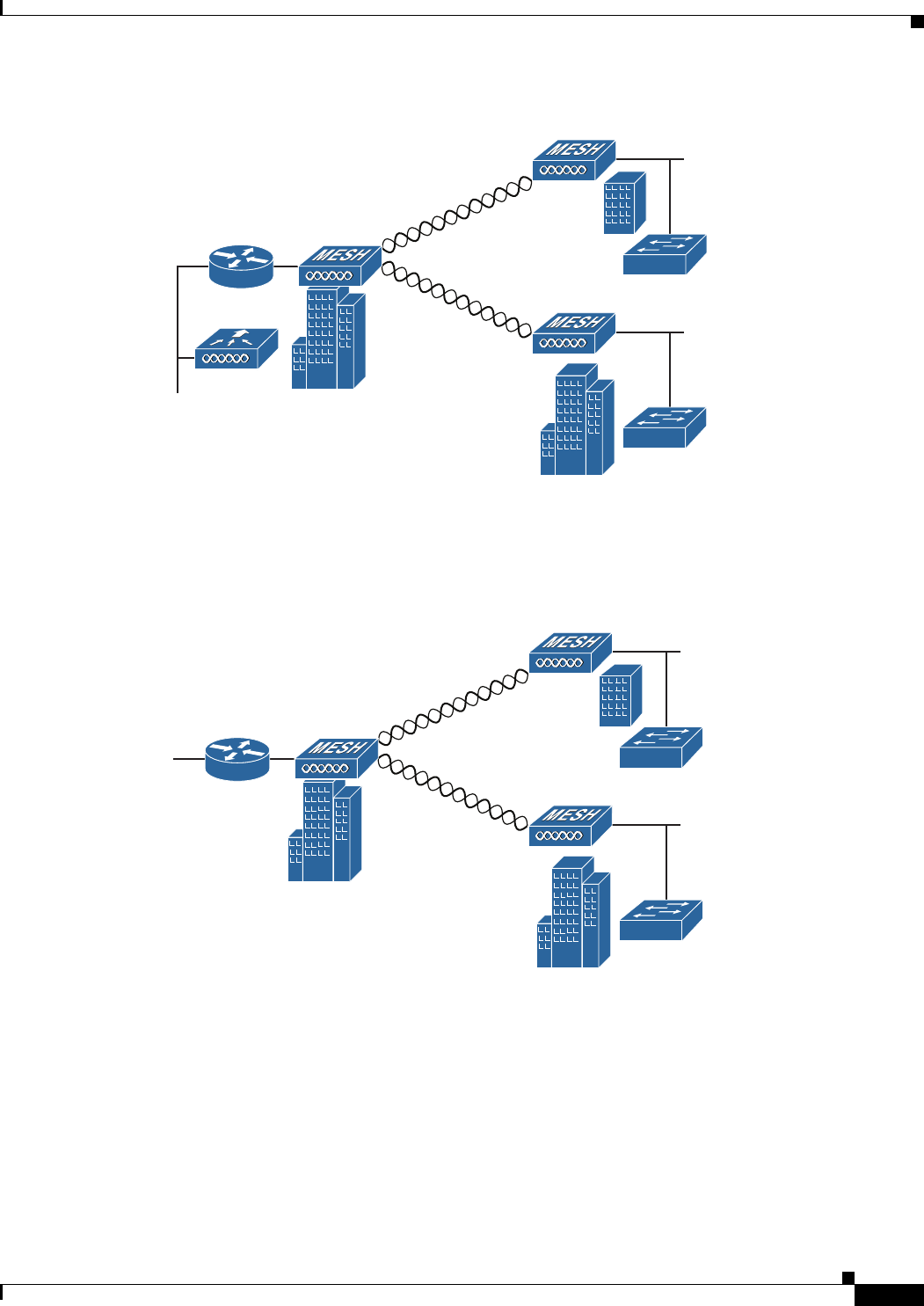
Point-to-Multipoint Bridging
The access points can be used as a RAP to connect multiple remote MAPs with their associated wired
networks. By default this capability is turned-off for all access points. To support Ethernet bridging, you
must enable bridging on the controller for each access point. Wireless client access can be provided over
the bridging link; however, if bridging between tall buildings, the 2.4-GHz wireless coverage area may
be limited and possibly not suitable for direct wireless client access. Figure 1-10 illustrates an example
of access point-to-multipoint bridging.
255495
(5 GHz)
352052
2.4 GHz or 5 GHz
1-15
Cisco Aironet 1560 Series Outdoor Access Point Hardware Installation Guide
Chapter 1 Overview
Network Deployment Examples
Figure 1-10 Access Point to Multipoint Bridging Example
The access points can also support point-to-multipoint bridging under autonomous mode. In this
autonomous mode, the bridging can be done on the 2.4 or 5 GHz radio, but not both. In this mode, one
access point is designated as the root and the other end is designated as the non-root bridge.
Figure 1-11 Access Point to Multipoint Bridging in Autonomous Mode
255494
(5 GHz)
(5 GHz)
352051
2.4 GHz or 5 GHz
2.4 GHz or 5 GHz
1-16
Cisco Aironet 1560 Series Outdoor Access Point Hardware Installation Guide
Chapter 1 Overview
Network Deployment Examples
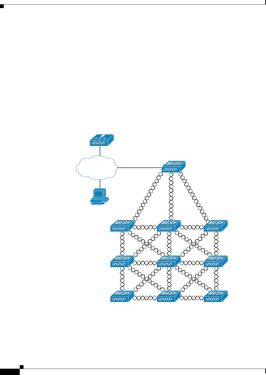
Point-to-Multipoint Mesh Network
The access point is typically deployed in a mesh network configuration. In a typical mesh deployment,
one or more RAPs have a wired network connection through a switch to a controller. Other remote MAPs
without wired network connections use the backhaul feature to optimally link to a RAP that is connected
to the wired network. In the mesh network, the links between the access points are referred to as the
backhaul links.
Intelligent wireless routing is provided by the Adaptive Wireless Path protocol (AWPP). This enables
each MAP to identify its neighbors and intelligently choose the optimal path to the RAP with the wired
network connection by calculating the cost of each path in terms of signal strength and the number of
hops required to get to a controller with signal strength given priority since signal strength determines
the data rate available for backhaul.
Figure 1-12 illustrates a typical mesh configuration using MAPs and RAPs.
Figure 1-12 Typical Mesh Configuration Using Access Points
351994
CPI
Network
RAP
MAP 1 MAP 2 MAP 3
MAP 4 MAP 6
MAP 5
MAP 7 MAP 8 MAP 9
1-17
Cisco Aironet 1560 Series Outdoor Access Point Hardware Installation Guide
Chapter 1 Overview
Network Deployment Examples
Layer 3 Network Operation
The access points support Layer 3 network operation. Access points and controllers in Layer 3
configurations use IP addresses and UDP packets, which can be routed through large networks. Layer 3
operation is scalable and recommended by Cisco.
Figure 1-13 illustrates a typical Layer-3 wireless network configuration containing access points and a
controller.
Figure 1-13 Typical Layer 3 Access Point Network Configuration Example
148458

1-18
Cisco Aironet 1560 Series Outdoor Access Point Hardware Installation Guide
Chapter 1 Overview
Network Deployment Examples

CHAPTER
2-1
Cisco Aironet 1560 Series Outdoor Access Point Hardware Installation Guide
2
Installing the Access Point
This chapter describes how to install the 1560 access point and contains the following sections:
•Unpacking the Access Point, page 2-2
•Tools and Hardware, page 2-2
•Safety Warnings, page 2-4
•Before Beginning the Installation, page 2-8
•Becoming Familiar with Access Point Installation Components, page 2-9
•Mounting the Access Point, page 2-11
•Installing Antennas, page 2-35
•Grounding the Access Point, page 2-48
•Powering the Access Point, page 2-49
•Configuring the Access Point, page 2-65
•What to Do Next, page 2-66

2-2
Cisco Aironet 1560 Series Outdoor Access Point Hardware Installation Guide
Chapter 2 Installing the Access Point
Unpacking the Access Point
Unpacking the Access Point
To unpack the access point, follow these steps:
Step 1 Open the shipping container and carefully remove the contents.
Step 2 Return all packing materials to the shipping container, and save it.
Step 3 Ensure that all items listed in “Package Contents” are included in the shipment. If any item is damaged
or missing, notify your authorized Cisco sales representative.
Package Contents
Each access point package contains the following items:
•One 1560 series access point
•Two-pin DC power connector
•Ground lug and screws with lock washers
•Plastic cable gland and rubber seal
•Weatherization tape and anti-corrosion sealant
•Cisco product documentation and pointer card
Tools and Hardware
The tools and hardware used to install the 1560 access point are described in:
•Optional Tools and Hardware, page 2-2
•Optional Tools and Hardware That You Supply, page 2-3
•Safety Warnings, page 2-4
•Safety Warnings, page 2-4
Optional Tools and Hardware
Depending on what you ordered, the following optional equipment may be part of your shipment:
•External antennas, depending on which ones you purchased (See “AP1562E (External Antenna)”
section on page 1-10 for information on available external antennas.)
•Wall/Pole mount bracket AIR-ACC1530-PMK1(=)
•Wall/Pole mount bracket for AP and AC/DC power adapter AIR-ACC1560-PMK1(=)
•Wall/Pole mount bracket with tilt mechanism, spare only AIR-ACC1530-PMK2(=)
•Street light power tap (AIR-PWR-ST-LT-R3P=), works only with the AC/DC power adapter.
•Power injector AIR-PWRINJ6=
•AP cover / Solar Shield for 1560, spare only (AIR-ACC1560-CVR=)

2-3
Cisco Aironet 1560 Series Outdoor Access Point Hardware Installation Guide
Chapter 2 Installing the Access Point
Tools and Hardware
•AC/DC power adapter, spare only AIR-PWRADPT-RGD1=
•AIR-PWRINJ-60-PMK= mounting bracket for AIR-PWRADPT-RGD1=
•Spare Parts kit containing extra cable glands, power connector, ground lug, etc.
(AIR-ACC1530-KIT1=)
•AIR-PWRINJ-60RGD1=
•AIR-PWRINJ-60RGD2=
•AIR-PWRINJ-30RGD1=
•FIPS kit (AIRLAP-FIPSKIT=)
•Lightning Arrestor kit (AIR-ACC245LA-N=)
Optional Tools and Hardware That You Supply
Tools and materials that are user-supplied are:
•Ground lug crimping tool (Panduit CT-720 with CD-720-1 die)
•6-AWG copper ground wire
•10 mm open end or box wrench
•13 mm box-end wrench or socket set
•16 mm box-end wrench or socket set
•Large flat or Phillips screw driver (for port plugs)
•Small flat screwdriver for DC power connector
•Optional shielded outdoor-rated Ethernet (CAT5e or better) cable with 0.20 to 0.35 in
(0.51 to 0.89 cm) diameter
•Optional Ethernet RJ-45 connector and installation tool
•Optional shielded outdoor-rated DC power cable with 0.20 to 0.35 inch (.0.51 to 0.89 cm) diameter
•Optional ground rod, as required by local regulations
•Optional ladder, power lift, rope, or other tools as required

2-4
Cisco Aironet 1560 Series Outdoor Access Point Hardware Installation Guide
Chapter 2 Installing the Access Point
Safety Warnings
Safety Warnings
Translated versions of all safety warnings are available in the safety warning document that shipped with
your access point or on Cisco.com. To browse to the document on Cisco.com, refer to Appendix A,
“Translated Safety Warnings” for instructions.
Additional safety information, along with regulatory information, is provided in Appendix B,
“Declarations of Conformity and Regulatory Information”.
Warning
IMPORTANT SAFETY INSTRUCTIONS
This warning symbol means danger. You are in a situation that could cause bodily injury. Before you
work on any equipment, be aware of the hazards involved with electrical circuitry and be familiar
with standard practices for preventing accidents. Use the statement number provided at the end of
each warning to locate its translation in the translated safety warnings that accompanied this device.
Statement 1071
SAVE THESE INSTRUCTIONS
Warning
This equipment is to be installed by trained and qualified personnel, as per these installation
instructions. The installer is responsible for obtaining any required local or national safety
inspections of the structural integrity of the installation by the local authority/inspection department.
Warning
Do not operate the unit near unshielded blasting caps or in an explosive environment unless the
device has been modified to be especially qualified for such use.
Statement 364
Warning
The cables specified in this installation guide that are used with the specified cable glands provide
protection against ingress of moisture for a Type 4/IP67 classified enclosure. If substitute cable are
used, the installer must ensure that the size (OD) of the cable meets the acceptable range allowed by
the cable gland.
Warning
This equipment must be externally grounded using a customer-supplied ground wire before power is
applied. Contact the appropriate electrical inspection authority or an electrician if you are uncertain
that suitable grounding is available.
Statement 366
Warning
Read the installation instructions before connecting the system to the power source.
Statement 1004
Warning
Ultimate disposal of this product should be handled according to all national laws and regulations.
Statement 1040

2-5
Cisco Aironet 1560 Series Outdoor Access Point Hardware Installation Guide
Chapter 2 Installing the Access Point
Safety Warnings
FCC Safety Compliance Statement
The FCC, with its action in ET Docket 96-8, has adopted a safety standard for human exposure to RF
electromagnetic energy emitted by FCC-certified equipment. When used with approved Cisco Aironet
antennas, Cisco Aironet products meet the uncontrolled environmental limits found in OET-65 and ANSI
C95.1, 1991. Proper operation of this radio device according to the instructions in this publication results
in user exposure substantially below the FCC recommended limits.
Safety Precautions
Warning
Do not work on the system or connect or disconnect cables during periods of lightning activity.
Statement 1001
Warning
A readily accessible two-poled disconnect device must be incorporated in the fixed wiring.
Statement 1022
Warning
To reduce the risk of fire, use only No. 26 AWG or larger telecommunication line cord.
Statement 1023
Warning
This unit might have more than one power supply connection. All connections must be removed to
de-energize the unit.
Statement 1028
Warning
Only trained and qualified personnel should be allowed to install, replace, or service this equipment.
Statement 1030
Warning
Connect the unit only to DC power source that complies with the safety extra-low voltage (SELV)
requirements in IEC 60950 based safety standards.
Statement 1033
Warning
When installing or replacing the unit, the ground connection must always be made first and
disconnected last.
Statement 1046.
Warning
Do not locate the antenna near overhead power lines or other electric light or power circuits, or
where it can come into contact with such circuits. When installing the antenna, take extreme care
not to come into contact with such circuits, because they may cause serious injury or death. For
proper installation and grounding of the antenna, please refer to national and local codes (for
example, U.S.:NFPA 70, National Electrical Code, Article 810, Canada: Canadian Electrical Code,
Section 54).
Statement 1052

2-6
Cisco Aironet 1560 Series Outdoor Access Point Hardware Installation Guide
Chapter 2 Installing the Access Point
Safety Warnings
Caution Before connecting or disconnecting a power cord, you must remove power from the power cord using a
suitable service disconnect.
For safety and to achieve a good installation, please read and follow these safety precautions:
•Select your installation site with safety, as well as performance in mind. Remember: electric power
lines and phone lines look alike. For safety, assume that any overhead line can kill.
•Call your electric power company. Tell them your plans, and ask them to come look at your proposed
installation.
•Plan your installation carefully and completely before you begin. Successful raising of a mast or
tower is largely a matter of coordination. Each person should be assigned to a specific task and
should know what to do and when to do it. One person should be in charge of the operation to issue
instructions and watch for signs of trouble.
•When installing the access point and antennas, remember:
–
Do not use a metal ladder.
–
Do not work on a wet or windy day.
–
Do dress properly—shoes with rubber soles and heels, rubber gloves, long sleeved shirt or
jacket.
•Use a rope to lift the access point. If the assembly starts to drop, get away from it and let it fall.
•If any part of the antenna system should come in contact with a power line, do not touch it or try to
remove it yourself. Call your local power company. They will remove it safely.
If an accident should occur, call for qualified emergency help immediately.
Avoiding Damage to Radios in a Testing Environment
The radios on outdoor units (bridges) have higher transmit power levels than radios on indoor units
(access points). When you test high-power radios in a link, you must avoid exceeding the maximum
receive input level for the receiver. At levels above the normal operating range, packet error rate (PER)
performance is degraded. At even higher levels, the receiver can be permanently damaged. To avoid
receiver damage and PER degradation, you can use one of the following techniques:
•Separate the omnidirectional antennas by at least 2 ft (0.6 m) to avoid receiver damage or by at least
25 ft (7.6 m) to avoid PER degradation.
Note These distances assume free space path loss and are conservative estimates. Required separation
distances for damage and performance degradation levels in actual deployments are less if
conditions are not non-line-of-sight.
•Reduce the configured transmit power to the minimum level.
•Use directional antennas, and keep them away from each other.
•Cable the radios together using a combination of attenuators, combiners, or splitters to achieve a total
attenuation of at least 60 dB.
For a radiated test bed, the following equation describes the relationships among transmit power, antenna
gain, attenuation, and receiver sensitivity:
txpwr + tx gain + rx gain - [attenuation due to antenna spacing] < max rx input level

2-7
Cisco Aironet 1560 Series Outdoor Access Point Hardware Installation Guide
Chapter 2 Installing the Access Point
Safety Warnings
Where:
txpwr = Radio transmit power level
tx gain = transmitter antenna gain
rx gain = receiver antenna gain
For a conducted test bed, the following equation describes the relationships among transmit power,
antenna gain, and receiver sensitivity:
txpwr - [attenuation due to coaxial components] < max rx input level
Caution Under no circumstances should you connect the antenna port from one access point to the antenna port
of another access point without using an RF attenuator. If you connect antenna ports, you must not
exceed the maximum survivable receive level of 0 dBm. Never exceed 0 dBm, or damage to the access
point can occur. Using attenuators, combiners, and splitters having a total of at least 60 dB of attenuation
ensures that the receiver is not damaged and that PER performance is not degraded.
Installation Guidelines
Because the access point is a radio device, it is susceptible to common causes of interference that can
reduce throughput and range. Follow these basic guidelines to ensure the best possible performance:
•For information on planning and initially configuring your Cisco Mesh network, refer to the Cisco
Wireless Access Points, Design and Deployment Guide, Release 7.3.
•Review the FCC guidelines for installing and operating outdoor wireless LAN devices at
http://www.cisco.com/c/en/us/products/collateral/routers/3200-series-rugged-integrated-services-r
outers-isr/data_sheet_c78-647116.html.
•Perform a site survey before beginning the installation.
•Install the access point in an area where structures, trees, or hills do not obstruct radio signals to and
from the access point.
•The access points can be installed at any height, but best throughput is achieved when all the access
points are mounted at the same height. We recommend installing the access points no higher than
40 feet to allow support for wireless clients on the ground.
•The Console port is under a sealed plugs Inspect the seal of the plug at the time of installation. Every
time the plug is removed or replaced, properly tighten it. Tighten the plug to 15 lbf-in. If you do not
tighten the plug properly, it will not meet IP67 criteria, and may lead to water leaking into the unit.
•If the DC power port, SFP port, or the PoE-In port is not in use, then the port’s covering plug must
be tightened to 12.5 lbf-in torque. Otherwise, it may lead to water leaking into the access point.
Note To calculate path loss and to determine how far apart to install access points, consult an RF planning
expert.
Site Surveys
Every network application is a unique installation. Before installing multiple access points, you should
perform a site survey to determine the optimum use of networking components and to maximize range,
coverage, and network performance.

2-8
Cisco Aironet 1560 Series Outdoor Access Point Hardware Installation Guide
Chapter 2 Installing the Access Point
Before Beginning the Installation
Site surveys reveals problems that can be resolved before the network is operational. Because
802.11a/b/g/n operates in an unlicensed spectrum, there may be sources of interference from other
802.11a wireless devices (especially in multi-tenant buildings) that could degrade your 802.11 signals.
A site survey can determine if such interference exists at the time of deployment.
A proper site survey involves temporarily setting up mesh links and taking measurements to determine
whether your antenna calculations are accurate. Determine the correct locations and antenna types
before you drill holes and route cables and mounting equipment.
Consider the following operating and environmental conditions when performing a site survey:
•Data rates—Sensitivity and range are inversely proportional to data bit rates. The maximum radio
range is achieved at the lowest workable data rate. A decrease in receiver sensitivity occurs as the
radio data increases.
•Antenna type and placement—Proper antenna configuration is a critical factor in maximizing radio
range. As a general rule, range increases in proportion to antenna height. However, do not place the
antenna higher than necessary, because the extra height also increases potential interference from
other unlicensed radio systems and decreases the wireless coverage from the ground.
•Physical environment—Clear or open areas provide better radio range than closed or filled areas.
•Obstructions—Physical obstructions such as buildings, trees, or hills can hinder performance of
wireless devices. Avoid locating the devices in a location where there is an obstruction between the
sending and receiving antennas.
•How far is your wireless link?
•Has a previous site survey been conducted?
•Do you have a clear Fresnel zone between the access points or radio line of sight?
•What is the minimum acceptable data rate within the link?
•Do you have the correct antenna (if more than one antenna is being offered?)
•Do you have access to both of the mesh site locations?
•Do you have the proper permits, if required?
•Are you following the proper safety procedures and practices?
•Have you configured the access points before you go onsite? It is always easier to resolve
configurations or device problems first.
•Do you have the proper tools and equipment to complete your survey.
Before Beginning the Installation
Before you begin the installation process:
•Ensure that a site survey has been performed.
•Ensure that your network infrastructure devices are operational and properly configured.
•Ensure that your controllers are connected to switch trunk ports.
•Ensure that your switch is configured with untagged access ports for connecting your access points.
•Ensure that a DHCP server with Option 43 configured is reachable by your access points, or
manually configure the controller information in the access point (for additional information, refer
to the “Configuring DHCP Option 43” section on page F-1).
2-9
Cisco Aironet 1560 Series Outdoor Access Point Hardware Installation Guide
Chapter 2 Installing the Access Point
Becoming Familiar with Access Point Installation Components
•Become familiar with the access point installation components (see the “Becoming Familiar with
Access Point Installation Components” section on page 2-9).
Becoming Familiar with Access Point Installation Components
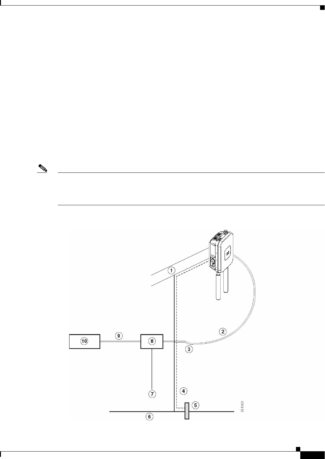
The access point is designed to be installed in an outdoor environment, such as the exterior roof overhang
of a tall building or a streetlight pole. Carefully review the following figures to become familiar with the
system components, connectors, indicators, cables, system interconnection, and grounding:
•Components in a typical access point installation (see Figure 2-1)
•Pole mount installation (see Figure 2-2)
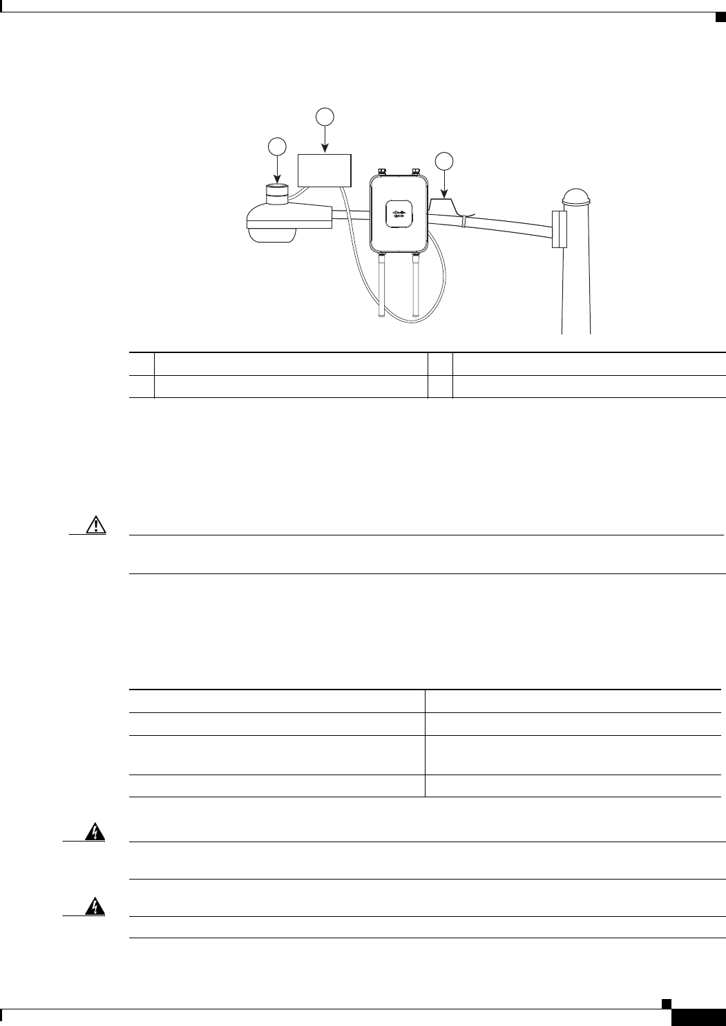
•Streetlight power tap installation, works only with the AC/DC power adapter (see Figure 2-3). For
information on how to connect to Streetlight AC power, see Connecting Streetlight AC Power.
Note that this type of deployment requires an alternate AP mounting kit. See Mounting the Access
Point section for more information.
Note The illustrations in this document show all available connections for the access point. Unused
connections are capped with a connector plug to ensure the watertight integrity of the access point. Cable
glands are provided for connector openings, which can be installed before or after deploying the access
point.
Figure 2-1 Components in a Typical Access Point Installation
2-10
Cisco Aironet 1560 Series Outdoor Access Point Hardware Installation Guide
Chapter 2 Installing the Access Point
Becoming Familiar with Access Point Installation Components
Warning
Installation of the equipment must comply with local and national electrical codes.
Statement 1074
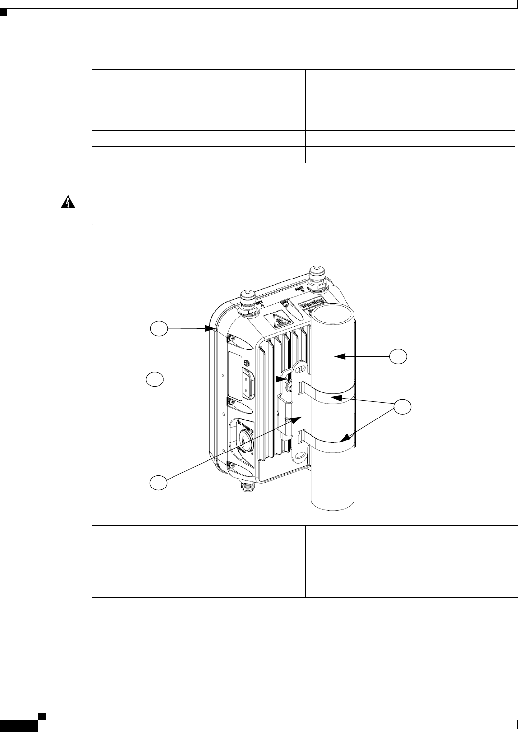
Figure 2-2 Standard Pole Mount Installation
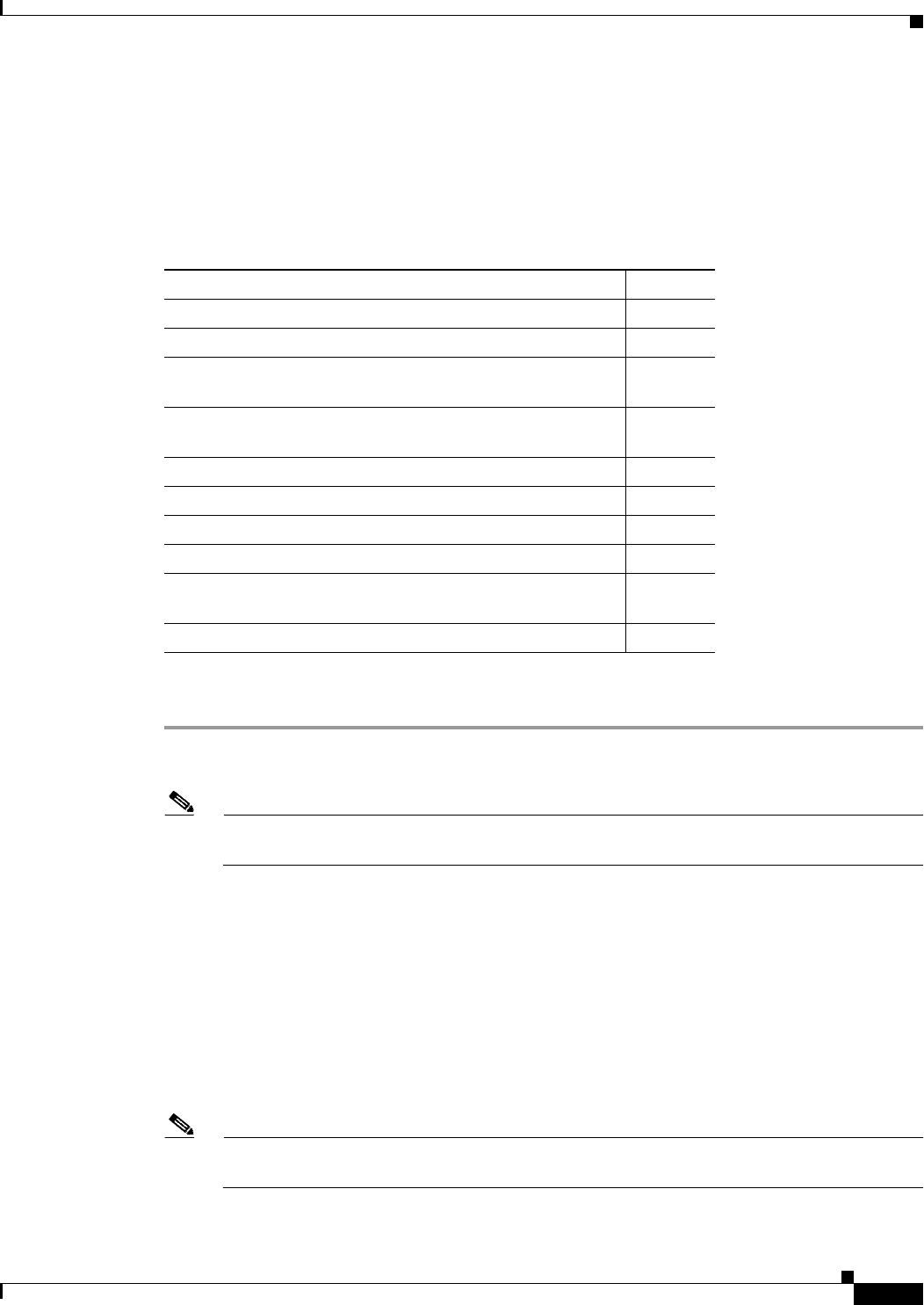
1Building roof-overhang 6Ground
2Shielded outdoor-rated Ethernet
(CAT5e or better) cable1
1. User supplied.
7Power cord
3Water drip loop 8Power injector
46-AWG copper grounding wire1 9Shielded Ethernet (CAT5e or better) cable1
5Ground rod1 10 Controller (through a switch)
1Access point model AIR-AP1562E-x-K9 3Mounting bracket (part of pole mount kit)
2One of four M6 AP mount hole and key hole
slots
4Stainless steel mounting straps (part of pole
mount kit)
5Pole (wood, metal, or fiberglass)
2 in. to 8 in. (50 mm to 203 mm) diameter
5
4
1
2
3
2-11
Cisco Aironet 1560 Series Outdoor Access Point Hardware Installation Guide
Chapter 2 Installing the Access Point
Mounting the Access Point
Figure 2-3 Streetlight Power Tap Adapter Installation
Mounting the Access Point
This section provides instructions for installing your access points. Personnel installing the access point
must understand wireless access points and bridging techniques and grounding methods.
Caution All installation methods for mounting an access point on any wall surface is subject to the acceptance of
local jurisdiction.
AP Mounting Options
The 1560 Series Access Point can be wall, pole or tower mounted. The available mounting kits are
provided in the table below.
Warning
Only trained and qualified personnel should be allowed to install, replace, or service this equipment.
Statement 1030
Warning
Installation of the equipment must comply with local and national electrical codes.
Statement 1074
1Outdoor light control 36-AWG copper grounding wire
2AC/DC power adapter
962
1
2
3
AC/DC
Adapter
AP Mounting Kit Purpose
AIR-ACC1530-PMK1= Fixed mounting kit for wall and pole mounting.
AIR-ACC1560-PMK1= Fixed mounting kit, allowing mounting of both
AP and power supply, for wall and pole mounting.
AIR-ACC1530-PMK2= Pivoted mounting kit for wall and pole mounting.

2-12
Cisco Aironet 1560 Series Outdoor Access Point Hardware Installation Guide
Chapter 2 Installing the Access Point
Mounting the Access Point
Access Point Mounting Orientation
When mounting an access point on a horizontal or vertical surface, you must ensure that the access
point is oriented with the LED indicators pointing down. This positioning allows LEDs to be visible
to someone on the ground below the access point.
You must also ensure the access point is mounted in such a way as to ensure that all antenna ports and
the console port are accessible for future use.
Note Omnidirectional antennas are vertically polarized and should be mounted vertically.
2-13
Cisco Aironet 1560 Series Outdoor Access Point Hardware Installation Guide
Chapter 2 Installing the Access Point
Mounting the Access Point
Wall Mounting the Access Point with AIR-ACC1530-PMK1= Mounting Kit
The AIR-ACC1530-PMK1= mounting kit contains a mounting bracket for wall mounting or pole
mounting. You can use the mounting bracket as a template to mark the positions of the mounting holes
for your installation. You then install the mounting plate, and attach the access point when you are
ready. Table 2-1 lists the materials you will need to provide in addition to the fixed mounting kit.
Ta b l e 2 - 1 Materials Required to Mount Access Point to a Vertical Wall
Caution The mounting surface, attaching screws and optional wall anchors must be able to support a
50-lb (22.7 kg) static weight.
To mount the access point on a vertical wall, follow these instructions:
Step 1 Use the mounting bracket as a template to mark four screw hole locations on the mounting surface.
See Figure 2-4 for the mounting bracket screw hole locations. Use the mounting slotted holes to attach
the unit to the wall.
Materials Required to Mount Access Point to a Vertical Wall In Kit
Ground lug and screws (provided with access point) Yes
Wall Mount Bracket Yes
Four M6 x 12-mm Hex-head Bolts Yes
Crimping tool for ground lug, Panduit CT-720 with CD-720-1
die (http://www.panduit.com)
No
Four wall mounting screws No
Four wall anchors (specified for all material) No
Drill bit for wall anchors No
Electric drill and standard screwdriver No
#6 AWG ground wire No
Shielded outdoor-rated Ethernet (CAT5e or better) cable No
Grounding block No
Grounding rod No
10-mm box-end wrench or socket set No
2-14
Cisco Aironet 1560 Series Outdoor Access Point Hardware Installation Guide
Chapter 2 Installing the Access Point
Mounting the Access Point
Figure 2-4 Mounting Bracket for Wall and Pole Mounting
Step 2 Use four customer-supplied screws and optional screw-anchors to attach the mounting plate to the
mounting surface.
Note If necessary, use suitable screw anchors and an exterior-grade plywood backboard to mount the access
point to stucco, cement or drywall.
Figure 2-5 Mounting Bracket Dimensions
1Quick Mount Keyhole Slots (for AP use) 2Mounting Slots (used with the band clamps)
3Bracket Mount Holes (use bolts up to 1/4" or
6 mm in diameter)
347852
1
2
3

2-15
Cisco Aironet 1560 Series Outdoor Access Point Hardware Installation Guide
Chapter 2 Installing the Access Point
Mounting the Access Point
Step 3 Screw an M6 x12 mm bolt into each of the four support bolt holes on the back of the access point. Do
not screw the bolt all the way in; leave approximately a 0.13 inch (3.3 mm) space.
Step 4 Position the four bolts on the access point into the keyhole slots on the mounting bracket.
Step 5 Slide the access point down to sit securely in the quick mount notches.
Step 6 Using a 10mm wrench, secure the AP to the bracket by tightening the bolts to the bracket; torque to 40
lb-in.
Step 7 Continue with the Grounding the Access Point, page 2-48.
2-16
Cisco Aironet 1560 Series Outdoor Access Point Hardware Installation Guide
Chapter 2 Installing the Access Point
Mounting the Access Point
Wall Mounting the Access Point with AIR-ACC1560-PMK1= Mounting Kit
The AIR-ACC1560-PMK1= mounting kit contains a mounting bracket, for wall mounting or pole
mounting, the access point and the power supply together. You can use the mounting bracket as a
template to mark the positions of the mounting holes for your installation. You then install the
mounting plate, and attach the access point when you are ready. Table 2-1 lists the materials you will
need to provide in addition to the fixed mounting kit.
Ta b l e 2 - 2 Materials Required to Mount Access Point to a Vertical Wall
Caution The mounting surface, attaching screws and optional wall anchors must be able to support a
50-lb (22.7 kg) static weight.
To mount the access point on a vertical wall, follow these instructions:
Step 1 Use the mounting bracket as a template to mark four screw hole locations on the mounting surface.
See Figure 2-6 for the mounting bracket screw hole locations. Use the mounting slotted holes to attach
the unit to the wall.
Materials Required to Mount Access Point to a Vertical Wall In Kit
Ground lug and screws (provided with access point) Yes
Wall Mount Bracket Yes
Four M6 x 12-mm Hex-head Bolts Yes
Four #8-32 screws to mount the power supply Yes
Crimping tool for ground lug, Panduit CT-720 with CD-720-1
die (http://www.panduit.com)
No
Four wall mounting screws No
Four wall anchors (specified for all material) No
Drill bit for wall anchors No
Electric drill and standard screwdriver No
#6 AWG ground wire No
Shielded outdoor-rated Ethernet (CAT5e or better) cable No
Grounding block No
Grounding rod No
10-mm box-end wrench or socket set No
2-17
Cisco Aironet 1560 Series Outdoor Access Point Hardware Installation Guide
Chapter 2 Installing the Access Point
Mounting the Access Point
Figure 2-6 Mounting Bracket for Wall and Pole Mounting
Step 2 Use four customer-supplied screws and optional screw-anchors to attach the mounting plate to the
mounting surface.
Note If necessary, use suitable screw anchors and an exterior-grade plywood backboard to mount the access
point to stucco, cement or drywall.
1Quick Mount Keyhole Slots (for AP use) 23 of 6 bracket mount holes for fastening the
bracket to a wall. Use bolts up to 1/4" or 6 mm
in diameter.
3Screw holes for fastening the power supply to
the bracket.
2-18
Cisco Aironet 1560 Series Outdoor Access Point Hardware Installation Guide
Chapter 2 Installing the Access Point
Mounting the Access Point
Figure 2-7 Mounting Bracket Dimensions
Step 3 Screw an M6 x12 mm bolt into each of the four support bolt holes on the back of the access point. Do
not screw the bolt all the way in; leave approximately a 0.13 inch (3.3 mm) space.
Step 4 Position the four bolts on the access point into the keyhole slots on the mounting bracket.
Step 5 Slide the access point down to sit securely in the quick mount notches.
Step 6 Using a 10mm wrench, secure the AP to the bracket by tightening the bolts to the bracket; torque to 40
lb-in.
Step 7 Mount the power supply to the bracket with four #8-32 screws.
Step 8 Continue with the Grounding the Access Point, page 2-48.
2-19
Cisco Aironet 1560 Series Outdoor Access Point Hardware Installation Guide
Chapter 2 Installing the Access Point
Mounting the Access Point
Pole Mounting the Access Point with the AIR-ACC1530-PMK1= Kit
The AIR-ACC1530-PMK1= mounting kit contains a mounting bracket for wall mounting or pole
mounting.This kit can be used to install the access point on a pole, mast or streetlight. It supports metal,
wood or fiberglass poles from 2 to 8 inches in diameter.
Ta b l e 2 - 3 Materials Needed to Mount the AP on a Vertical Pole
To mount the access point onto a vertical pole or streetlight pole, follow these steps:
Step 1 Select a mounting location on the pole to mount the access point. You can attach the access point to any
pole with a diameter from 2 to 8 inches (5.1 to 20.1 cm).
Note If you will be using a streetlight power tap adapter, position the access point within 3 ft (1 m) of
the outdoor light control. The AC/DC adapter must be used with street light power tap.
Step 2 Determine which size of band clamp is needed based on the pole diameter. Slide the two clamps through
the top and bottom set of mounting slots (see Figure 2-8) and mount the bracket to the pole.
Step 3 Wrap the band clamps around the pole and slide them into the second set of top and bottom mounting
slots on the bracket. Lightly tighten the clamps. Only tighten them enough to keep the bracket from
sliding down the pole.
Step 4 Screw an M6 bolt into each of the four bolt holes on the back side of the access point. Do not screw the
bolt in all the way. Leave a gap of about 0.13" (3.3mm).
Step 5 Position the four bolts on the access point into the bracket keyhole slots. Check to be sure that the access
point is properly seated in the slots.(See Figure 2-8)
Note The access point should be positioned with the LEDs on the bottom to allow viewing from the
ground.
Materials Needed to Mount the AP on a Vertical Pole In Kit
One wall mount bracket Yes
Four M6 x12mm hex head bolts Yes
Two stainless steel band clamps (adjustable 2"–5", 51–127
mm)
Yes
Two stainless steel band clamps (adjustable 5"–8", 127–203
mm)
Yes
10 mm box-end wrench No
Outdoor rated shielded ethernet cable No
Ground lug (provided with the access point) Yes
Ground block and rod No
Crimping tool for ground lug, Panduit CT-720 with CD-720-1
die (http://www.panduit.com)
No
#6 AWG ground wire No
2-20
Cisco Aironet 1560 Series Outdoor Access Point Hardware Installation Guide
Chapter 2 Installing the Access Point
Mounting the Access Point
Step 6 Using a 10mm wrench, tighten the four bolts that connect the access point to the bracket to a torque of
40 lbf-in.
Step 7 Locate the access point to its final position. Tighten the band clamps with the wrench so that the access
point does not slide on the pole. Ensure that the clamps are tight enough to not let the AP move.
Step 8 Continue with the Grounding the Access Point, page 2-48.
Figure 2-8 AP and Fixed Mount Kit Installed on a Pole
1
3
4
2
1One of four M6 AP mount hole and key hole
slots
2Metal Band Straps
3Mounting Slots 4Pole
2-21
Cisco Aironet 1560 Series Outdoor Access Point Hardware Installation Guide
Chapter 2 Installing the Access Point
Mounting the Access Point
Pole Mounting the Access Point with the AIR-ACC1560-PMK2= Kit
The AIR-ACC1560-PMK2= fixed mounting kit contains a mounting bracket, for wall mounting or pole
mounting, the access point along with the power supply kit.This mounting kit supports metal, wood or
fiberglass poles from 2 to 8 inches in diameter.
Ta b l e 2 - 4 Materials Needed to Mount the AP on a Vertical Pole
To mount the access point onto a vertical pole or streetlight pole, follow these steps:
Step 1 Select a mounting location on the pole to mount the access point. You can attach the access point to any
pole with a diameter from 2 to 8 inches (5.1 to 20.1 cm).
Note If you will be using a streetlight power tap adapter, position the access point within 3 ft (1 m) of
the outdoor light control. The AC/DC adapter must be used with street light power tap.
Step 2 Determine which size of band clamp is needed based on the pole diameter. Slide the two clamps through
the top and bottom set of mounting slots (see Figure 2-9) and mount the bracket to the pole.
Step 3 Wrap the band clamps around the pole and slide them into the second set of top and bottom mounting
slots on the bracket. Lightly tighten the clamps. Only tighten them enough to keep the bracket from
sliding down the pole.
Step 4 Screw an M6 bolt into each of the four bolt holes on the back side of the access point. Do not screw the
bolt in all the way. Leave a gap of about 0.13" (3.3mm).
Step 5 Position the four bolts on the access point into the bracket keyhole slots. Check to be sure that the access
point is properly seated in the slots.(See Figure 2-9)
Note The access point should be positioned with the LEDs on the bottom to allow viewing from the
ground.
Materials Needed to Mount the AP on a Vertical Pole In Kit
One wall mount bracket Yes
Four M6 x12mm hex head bolts Yes
Four #8-32 screws to mount the power supply Yes
Three stainless steel band clamps (adjustable 2"–5", 51–127
mm)
Yes
Three stainless steel band clamps (adjustable 5"–8", 127–203
mm)
Yes
10 mm box-end wrench No
Outdoor rated shielded ethernet cable No
Ground lug (provided with the access point) Yes
Ground block and rod No
Crimping tool for ground lug, Panduit CT-720 with CD-720-1
die (http://www.panduit.com)
No
#6 AWG ground wire No
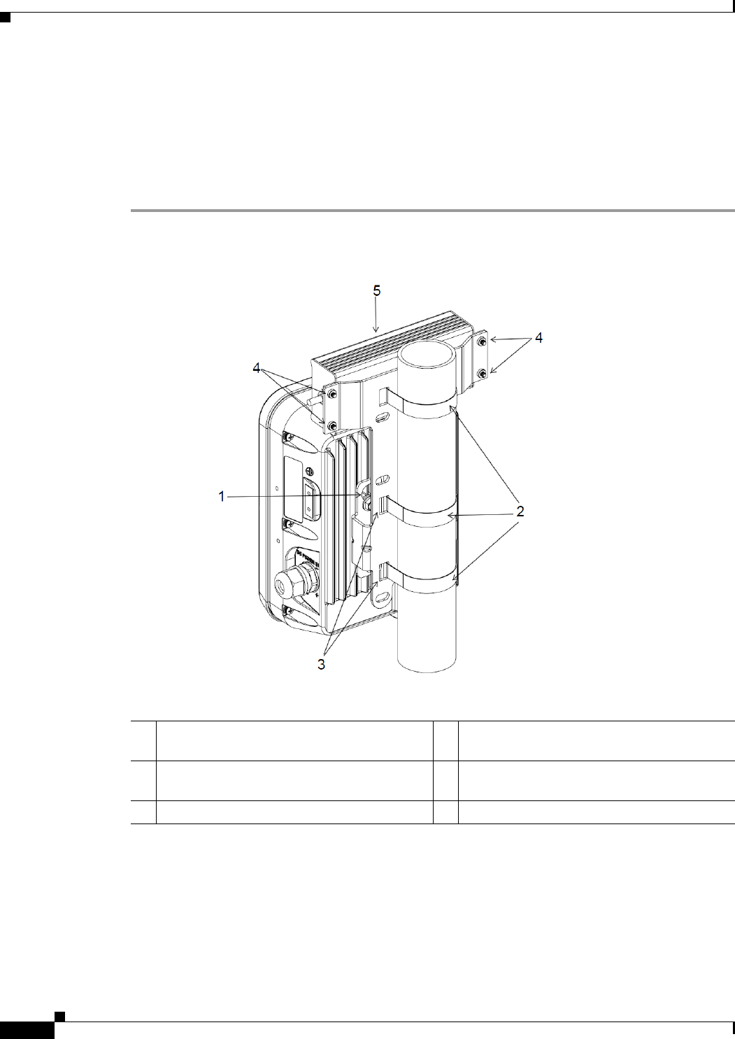
2-22
Cisco Aironet 1560 Series Outdoor Access Point Hardware Installation Guide
Chapter 2 Installing the Access Point
Mounting the Access Point
Step 6 Using a 10mm wrench, tighten the four bolts that connect the access point to the bracket to a torque of
40 lbf-in.
Step 7 Mount the power supply to the bracket with four #8-32 screws.
Step 8 Locate the access point to its final position. Tighten the band clamps with the wrench so that the access
point does not slide on the pole. Ensure that the clamps are tight enough to not let the AP move.
Step 9 Continue with the Grounding the Access Point, page 2-48.
Figure 2-9 AP and Fixed Mount Kit Installed on a Pole
1One of four M6 AP mount hole and key hole
slots
2Metal Band Straps
3Mounting Slots 4Screw holes for fastening power supply to the
bracket.
5Power supply mounted on the bracket.
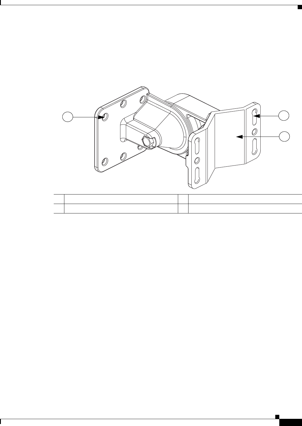
2-23
Cisco Aironet 1560 Series Outdoor Access Point Hardware Installation Guide
Chapter 2 Installing the Access Point
Mounting the Access Point
Wall Mounting the Access Point with the Pivoting Mounting Kit
The optional pivoting mounting kit contains a mounting bracket for wall or pole mounting. This kit can
be used to install the access point on a wall while still allowing for some freedom of movement. This
bracket supports metal, wood or fiberglass surfaces.
Figure 2-10 Pivoting Mounting Kit
1Mounting holes for the AP 2Slots for wall-mounting and band clamps.
3Wall mount bracket.
351493
12
3
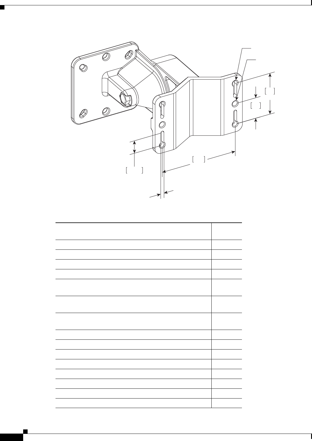
2-24
Cisco Aironet 1560 Series Outdoor Access Point Hardware Installation Guide
Chapter 2 Installing the Access Point
Mounting the Access Point
Figure 2-11 Pivoting Mounting Kit Dimensions
Table 2-5 Materials for Mounting on Wall with Pivoting Mounting Kit
352000
100
3.94
28
1.10
56
2.20
2x M8 THRU
4X 6.5MM THRU
17.10
.67
SLOT LENGTH [4.0]
.16
SLOT WIDTH
Materials Required for mounting AP on a vertical wall
with pivoting mounting kit
In Kit
Ground lug and screws (provided with access point) Yes
Pivoting mount kit and hardware Yes
(8) M6 x 12-mm Hex-head Bolts Yes
Adapter bracket for option horizontal mount Yes
Two stainless steel band clamps (adjustable 2"-5", 51 mm -
127 mm)
Yes
Two stainless steel band clamps (adjustable 5"-8", 127 mm -
203 mm)
Yes
Crimping tool for ground lug, Panduit CT-720 with CD-720-1
die (http://www.panduit.com)
No
Four wall mounting screws (6mm max) No
Four wall anchors (specified for all material) No
Drill bit for wall anchors No
Electric drill and standard screwdriver No
#6 AWG ground wire No
Shielded outdoor-rated Ethernet (CAT5e or better) cable No
Grounding block No
Grounding rod No
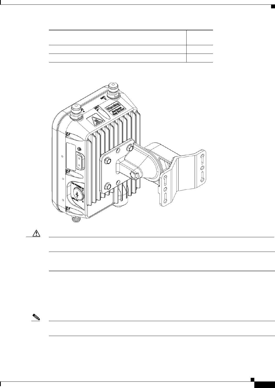
2-25
Cisco Aironet 1560 Series Outdoor Access Point Hardware Installation Guide
Chapter 2 Installing the Access Point
Mounting the Access Point
Figure 2-12 AP wall mounted with Pivoting Mounting Kit
Caution The mounting surface, attaching screws and optional wall anchors must be able to support a 50-lb (22.7
kg) static weight.
To mount the access point on a vertical wall, follow these instructions:
Step 1 Disassemble pivot kit, if not already done.
Step 2 Use the mounting bracket as a template to mark four screw hole locations on the mounting surface. See
Figure 2-10 for the mounting bracket screw hole locations (screw holes of maximum 6 mm in size).
Step 3 Use four customer-supplied screws and optional screw-anchors to attach the mounting plate to the
mounting surface.
Note If necessary, use suitable screw anchors and an exterior-grade plywood backboard to mount the access
point to stucco, cement or drywall.
Step 4 Match the holes in the bracket plate to the holes in the back of the access point.
Step 5 Screw an M8 x12 mm bolt into each of the four bolt holes (using a 10 mm box wrench or socket, torque
the bolts to 40 lbf-in) on the back side of the access point and mounting bracket.
13-mm box-end wrench or socket set No
10-mm box-end wrench No
Materials Required for mounting AP on a vertical wall
with pivoting mounting kit
In Kit
2-26
Cisco Aironet 1560 Series Outdoor Access Point Hardware Installation Guide
Chapter 2 Installing the Access Point
Mounting the Access Point
Step 6 Using the long bolt and the hardware supplied with the pivoting bracket, bolt the AP and its mounted
bracket, on to the bracket mounted on the wall (see Figure 2-14 for an exploded view of this assembly).
Step 7 Pivot the AP to your desired position, and then tighten the bolts (using a 13 mm wrench).
Step 8 Continue with Grounding the Access Point, page 2-48.
Pole Mounting the Access Point with the Pivoting Mounting Kit
The optional pivoting mounting kit contains a mounting bracket for wall mounting or pole mounting,
along with a clamp for pole mounting.This kit can be used to install the access point on a pole, mast or
streetlight. It supports metal, wood or fiberglass poles from 2 to 8 inches in diameter.
Figure 2-13 Pivoting Mounting Kit with Pole Mount Clamp
1Mounting holes for the access point 2Slots for band clamps (band clamps are
provided but not shown in this figure. See
Figure 2-15).
3Pole mount clamp. It can fit poles of range up
to 3 in. (76mm)
1
2
3
2-27
Cisco Aironet 1560 Series Outdoor Access Point Hardware Installation Guide
Chapter 2 Installing the Access Point
Mounting the Access Point
Figure 2-14 Exploded View of the Pivoting Mounting Kit
Table 2-6 Materials Needed to Mount the AP on a Vertical Pole with the Pivoting Mounting Kit
1
2
3
4
5
190.0 mm M8 screw 2M8 washer
3M8 spring washer 4M8 nut
580.0 mm M8 screw with washer and spring
washer
Materials Required In Kit
Ground lug and screws (provided with access point) Yes
Pivoting mount kit and hardware Yes
(8) M6 x 12-mm Hex-head Bolts Yes
Adapter bracket for option horizontal mount Yes
Two stainless steel band clamps (adjustable 2"-5", 51 mm -
127 mm)
Yes
Two stainless steel band clamps (adjustable 5"-8", 127 mm -
203 mm)
Yes

2-28
Cisco Aironet 1560 Series Outdoor Access Point Hardware Installation Guide
Chapter 2 Installing the Access Point
Mounting the Access Point
To mount the access point onto a vertical pole or streetlight pole, follow these steps:
Step 1 Select a mounting location on the pole to mount the access point. You can attach the access point to any
pole with a diameter from 2 to 8 inches (5.1 to 40.6 cm).
Note If you will be using a streetlight power tap adapter, position the access point within 3 ft (1 m) of the
outdoor light control.
Step 2 Mount the pivot bracket base to the pole using either one set of the adjustable band clamps or the screw
clamp (the screw clamp can be used on a pole that is not more than 3 inches in diameter).
Step 3 Position the pole clamp bracket on the pole as needed before tightening the metal bands. Tighten the
metal bands only enough to hold the bracket base in place, from sliding along the pole. Fully tighten the
bands only after the access point is positioned.
Step 4 Match the holes in the bracket plate to the holes in the back of the access point.
Step 5 Screw an M8 x12 mm bolt into each of the four bolt holes (using a 10 mm box wrench or socket, torque
the bolts to 40 lbf-in) on the back side of the access point and mounting bracket. (See Figure 2-14)
Note The access point should be positioned with the LEDs on the bottom to allow viewing from the ground.
Step 6 Mount the bracket with the AP, to the bracket on the pole. Use the long screw for this, as shown in the
exploded view – see Figure 2-14.
Step 7 Point the AP in the general desired position and tighten bolt, and then tighten the clamps on the pole.
The AP can be repositioned to its final position by loosening and re-tightening the bolts.
Crimping tool for ground lug, Panduit CT0720 with
CD-720-1 die (http://www.panduit.com)
No
Four wall mounting screws (6mm max) No
Four wall anchors (specified for all material) No
Drill bit for wall anchors No
Electric drill and standard screwdriver No
#6 AWG ground wire No
Shielded outdoor-rated Ethernet (CAT5e or better) cable No
Grounding block No
Grounding rod No
13-mm box-end wrench or socket set No
10-mm box-end wrench No
Materials Required In Kit
2-29
Cisco Aironet 1560 Series Outdoor Access Point Hardware Installation Guide
Chapter 2 Installing the Access Point
Mounting the Access Point
Figure 2-15 AP Pivot Mounted
Step 8 Continue with the Grounding the Access Point, page 2-48
Horizontally Mounting the Access Point with Optional Horizontal Mount Plate
The pivoting pole mount kit also contains a plate that allows the option of the AP enclosure to be
mounted horizontally (See Figure 2-16).
Table 2-7 Materials Needed to Mount the AP on a Vertical Pole with the Pivoting Mounting Kit
1Bolted Bracket Mounting Holes 2Mounting Slots
3Pole 4Metal Band Mounting Straps.
For the kit which uses a clamp instead of
metal bands, see Figure 2-13.
1
2
3
4
Materials Required In Kit
Ground lug and screws (provided with access point) Yes
Pivoting mount kit and hardware Yes
(8) M6 x 12-mm Hex-head Bolts Yes
Adapter bracket for option horizontal mount Yes
Two stainless steel band clamps (adjustable 2"-5", 51 mm -
127 mm)
Yes
Two stainless steel band clamps (adjustable 5"-8", 127 mm -
203 mm)
Yes
Crimping tool for ground lug, Panduit CT0720 with
CD-720-1 die (http://www.panduit.com)
No

2-30
Cisco Aironet 1560 Series Outdoor Access Point Hardware Installation Guide
Chapter 2 Installing the Access Point
Mounting the Access Point
Step 1 Mount the pivot bracket to a wall or a pole as shown in the previous procedures.
Step 2 Using four M6 x 12 mm bolts mount the horizontal adapter plate to the bracket mount plate.
Do not mount the pivot bracket mounting plate directly to the access point.
Step 3 Using the remaining four M6 x 12 mm bolts, mount the other side of the horizontal mounting plate to
the AP. See Figure 2-17 for the exploded view.
Step 4 Using a 10 mm wrench or socket, tighten all M6 bolts to 40 lbf-in (4.5 Nm).
Step 5 Position the access point as needed and tighten the mount kit bolts using a 13 mm wrench or socket.
Four wall mounting screws (6mm max) No
Four wall anchors (specified for all material) No
Drill bit for wall anchors No
Electric drill and standard screwdriver No
#6 AWG ground wire No
Shielded outdoor-rated Ethernet (CAT5e or better) cable No
Grounding block No
Grounding rod No
13-mm box-end wrench or socket set No
10-mm box-end wrench No
Materials Required In Kit
2-31
Cisco Aironet 1560 Series Outdoor Access Point Hardware Installation Guide
Chapter 2 Installing the Access Point
Mounting the Access Point
Figure 2-16 Access Point Horizontally Mounted using the Optional Horizontal Mount Plate
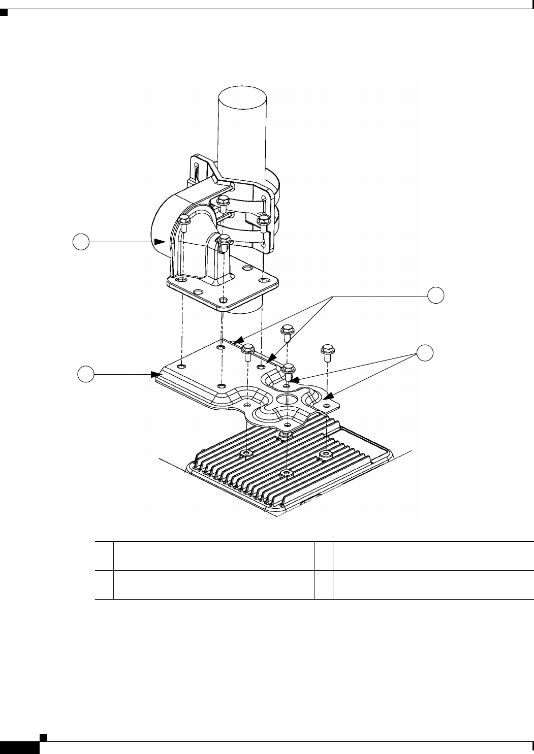
2-32
Cisco Aironet 1560 Series Outdoor Access Point Hardware Installation Guide
Chapter 2 Installing the Access Point
Mounting the Access Point
Figure 2-17 Exploded View of the Pivot Bracket Parts
1
2
3
4
1Pivoting bracket. Can be mounted on a pole or
a wall.
2Horizontal mounting plate
3Screw holes for mounting the horizontal
mounting plate to the pivoting bracket
4Screw holes for mounting the horizontal
mounting plate to the access point
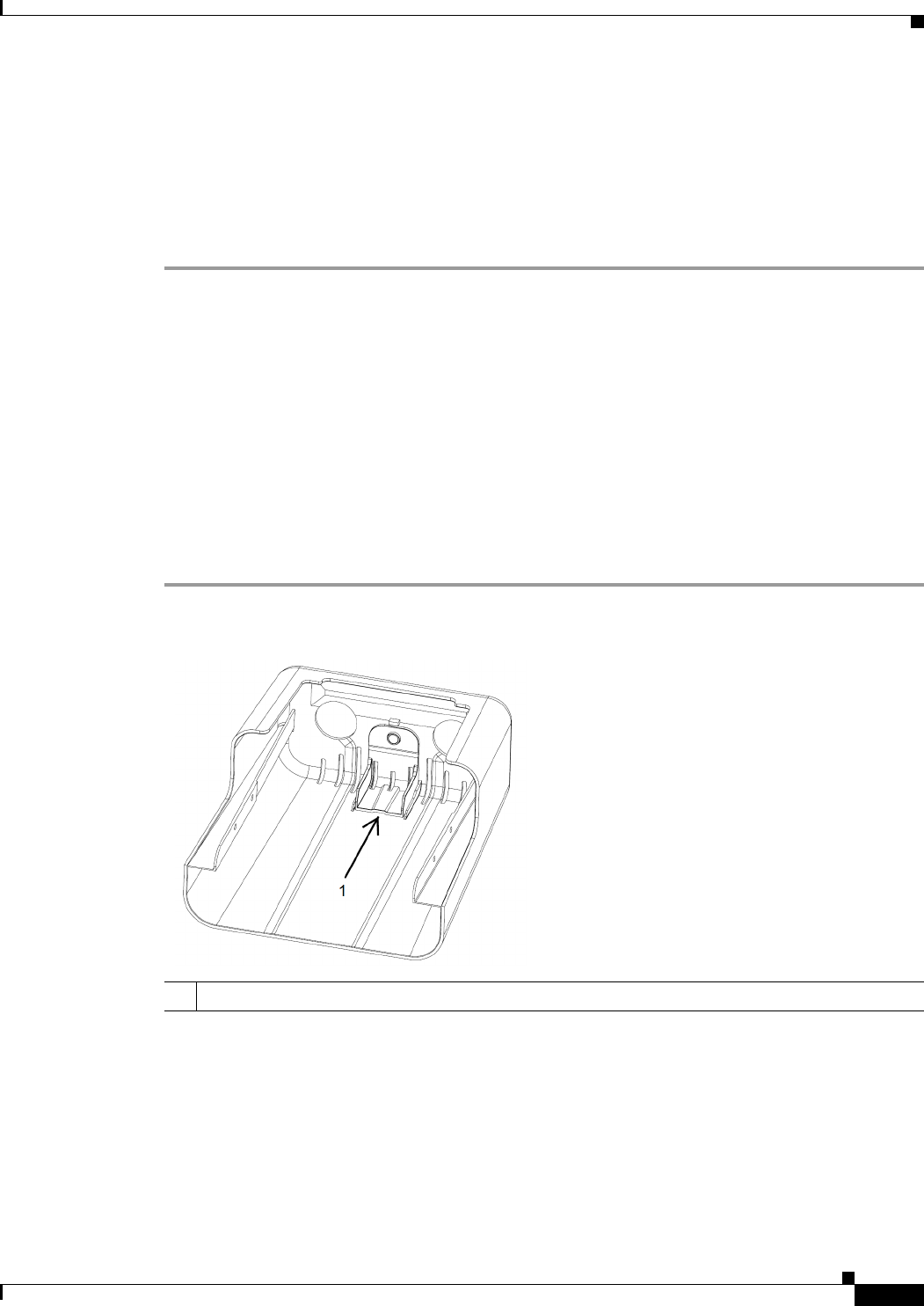
2-33
Cisco Aironet 1560 Series Outdoor Access Point Hardware Installation Guide
Chapter 2 Installing the Access Point
Installing AP Cover AIR-ACC1560-CVR=
Installing AP Cover AIR-ACC1560-CVR=
You can install an AP cover AIR-ACC1560-CVR=, which also acts as a a solar shield. The cover can be
installed prior to or after all connections are made. However, if remote cabled antennas are to be
installed, the shield must be installed before the antenna cables are attached to the AP.
Step 1 This step applies only to AP1562D models.
The cover AIR-ACC1560-CVR= is factory fitted with an adapter for installing on AP models AP1562I
and AP1562E. You need to remove this adapter before installing the cover on AP1562D AP models. For
this:
a. Slide a large flat blade screw driver into the opening shown in Figure 2-18.
b. Pry up the adapter while pushing the screw driver further into it, until the adapter pop out.
c. Discard the adapter.
Step 2 Position and slide the cover over the AP as shown in Figure 2-19.
Step 3 Align the two holes on each side of the cover with the screw holes on corresponding side of the AP.
Step 4 Insert and install #8-32 screws through the screw holes in the cover and into the AP. Tighten the screws
to 10 lb-in.
Figure 2-18 Only for AP1562D - Removing the Adapter from the Cover
1Slide a large flat blade screw driver into this opening and the pry the adapter out.
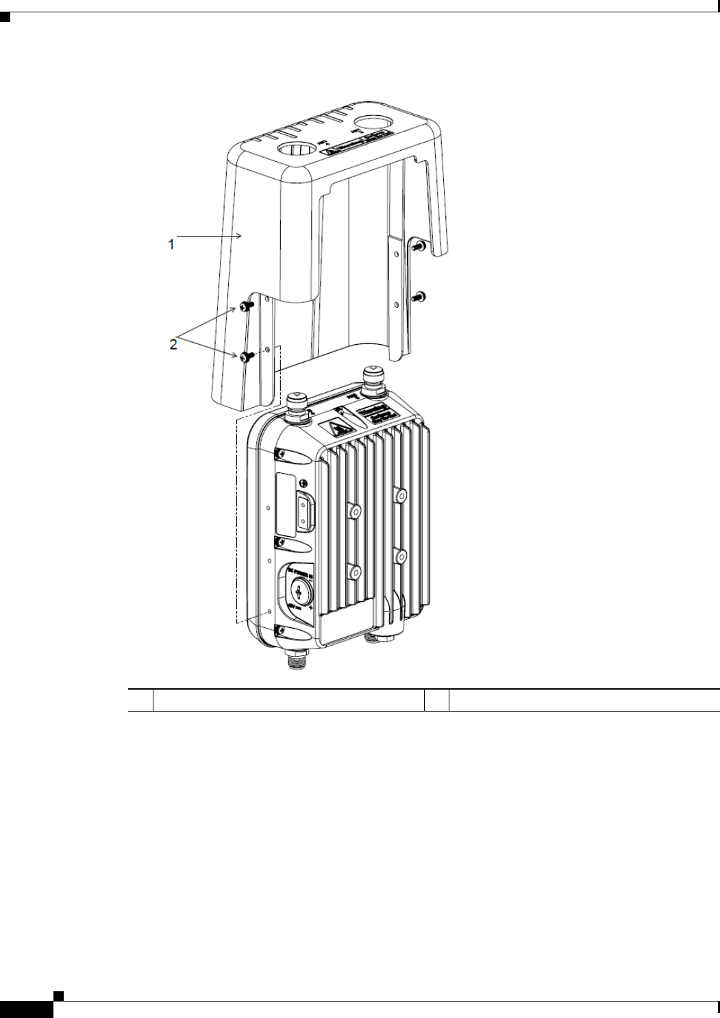
2-34
Cisco Aironet 1560 Series Outdoor Access Point Hardware Installation Guide
Chapter 2 Installing the Access Point
Installing AP Cover AIR-ACC1560-CVR=
Figure 2-19 Installing the Cover on the AP
1Solar Shield 2Two of four #8-32 screws
2-35
Cisco Aironet 1560 Series Outdoor Access Point Hardware Installation Guide
Chapter 2 Installing the Access Point
Installing Antennas
Installing Antennas
Table 2-8 shows the external antennas supported by the 1562E access point and provides required
quantities for each model.
For installation instructions and detailed information on these antennas, refer to the appropriate
document located at:
http://www.cisco.com/c/en/us/support/wireless/aironet-antennas-accessories/products-installation-guid
es-list.html
Follow all safety precautions when installing the antennas. For information on safety, refer to “Safety
Precautions when Installing Antennas” section on page 2-35.
Non-Cisco Antennas
Cisco does not support any third-party antennas. RF connectivity and compliance of third party antennas
is the customer’s responsibility. Cisco does not recommend any third-party antennas, and Cisco
Technical Assistance Center will not be able to provide any support for third-party antennas. Cisco’s
FCC Part 15 compliance is only guaranteed with Cisco antennas or antennas that are of the same design
and gain as Cisco antennas.
Safety Precautions when Installing Antennas
Warning
Do not locate the antenna near overhead power lines or other electric light or power circuits, or
where it can come into contact with such circuits. When installing the antenna, take extreme care
not to come into contact with such circuits, as they may cause serious injury or death. For proper
installation and grounding of the antenna, please refer to national and local codes (e.g. U.S.: NFPA 70,
National Electrical Code, Article 810, Canada: Canadian Electrical Code, Section 54).
Statement 280
1. Before you install an antenna, contact your Cisco account representative to explain which mounting
method to use for the size and type of antenna that you are about to install.
2. Select your installation site with safety, as well as performance, in mind. Remember that electric
power lines and phone lines look alike. For your safety, assume that any overhead line can kill you.
Table 2-8 1562E Access Point Supported External Antennas
Product ID
Frequency
Band Gain Type
AIR-ANT2547VG-N 2.4 / 5 GHz 4 / 7 dBi Omnidirectional (gray)
AIR-ANT2547V-N 2.4 / 5 GHz 4 / 7 dBi Omnidirectional (white)
AIR-ANT2588P3M-N= 2.4 / 5 GHz 8 / 8 dBi Directional
AIR-ANT2450V-N 2.4 GHz 5 dBi Omnidirectional
AIR-ANT2480V-N 2.4 GHz 8 dBi Omnidirectional
AIR-ANT2413P2M-N= 2.4 GHz 13 dBi Directional
AIR-ANT5180V-N 5 GHz 8 dBi Omnidirectional
AIR-ANT5114P2M-N= 5 GHz 14 dBi Directional

2-36
Cisco Aironet 1560 Series Outdoor Access Point Hardware Installation Guide
Chapter 2 Installing the Access Point
Installing Antennas
3. Contact your electric power company. Tell them your plans and ask them to come look at your
proposed installation.
4. Plan your installation carefully and completely before you begin. Each person involved in an
installation should be assigned to a specific task and should know what to do and when to do it. One
person should be in charge of the operation to issue instructions and watch for signs of trouble.
5. When installing your antenna, follow these guidelines:
–
Do not use a metal ladder.
–
Do not work on a wet or windy day.
–
Do dress properly—wear shoes with rubber soles and heels, rubber gloves, and a long-sleeved
shirt or jacket.
6. If the assembly starts to drop, move away from it and let it fall. Because the antenna, mast, cable,
and metal guy wires are all excellent conductors of electrical current, even the slightest touch of any
of these parts to a power line completes an electrical path through the antenna and the installer.
7. If any part of the antenna system should come in contact with a power line, do not touch it or try to
remove it yourself. Call your local power company to have it removed safely.
8. If an accident should occur with the power lines, call for qualified emergency help immediately.
Antenna Configurations
Integrated Antenna Option
The AP1562I uses an Integrated Low Profile Dual-Band 2.4-5 GHz Dipole Antenna Array. The antenna
contains an array of three dual-band dipole antennas. The three dipole antennas are contained within this
single radome, thereby greatly reducing the antenna’s visual footprint, and greatly reducing the
possibility of snagging the antenna on the cable bundle, the RF cable, or test cables. Each of thee three
dipole antennas is a dual-band antenna, covering both the 2.4 - 2.483 GHz band and the 5.25-5.85 GHz
bands. The antenna have a peak gain of about 3 dBi at 2.4 GHz and 5 dBi at 5 GHz. The antenna unit is
gray weatherproof radome for outdoor operations.
External Antenna Mounting Configurations
The selection of the antenna is determined in the configuration of the product. The 1562E antennas can
be mounted on a wall, pole and/or tower mounted. Please refer to the Ordering Guide for a list of
supported antennas.
The 1562E access point supports a variety of antennas designed for outdoor use with radios operating in
the 2.4-GHz and 5-GHz frequency bands. The 1562E supports the external antennas listed in the
following sections.
Cisco Aironet Dual-Band Omnidirectional Antenna (AIR-ANT2547V-N, AIR-ANT2547VG-N)
The Dual-Band Omnidirectional Antenna, referred to as a “stick” antenna, is designed for outdoor use
with Cisco Aironet Outdoor Access Points with radios operating in the 2.4-GHz and 5-GHz frequency
bands (Figure 2-20). Basic operating features of the antenna are:
•Omnidirectional collinear array
•Operates in the 2.4 GHz and 5 GHz frequency bands
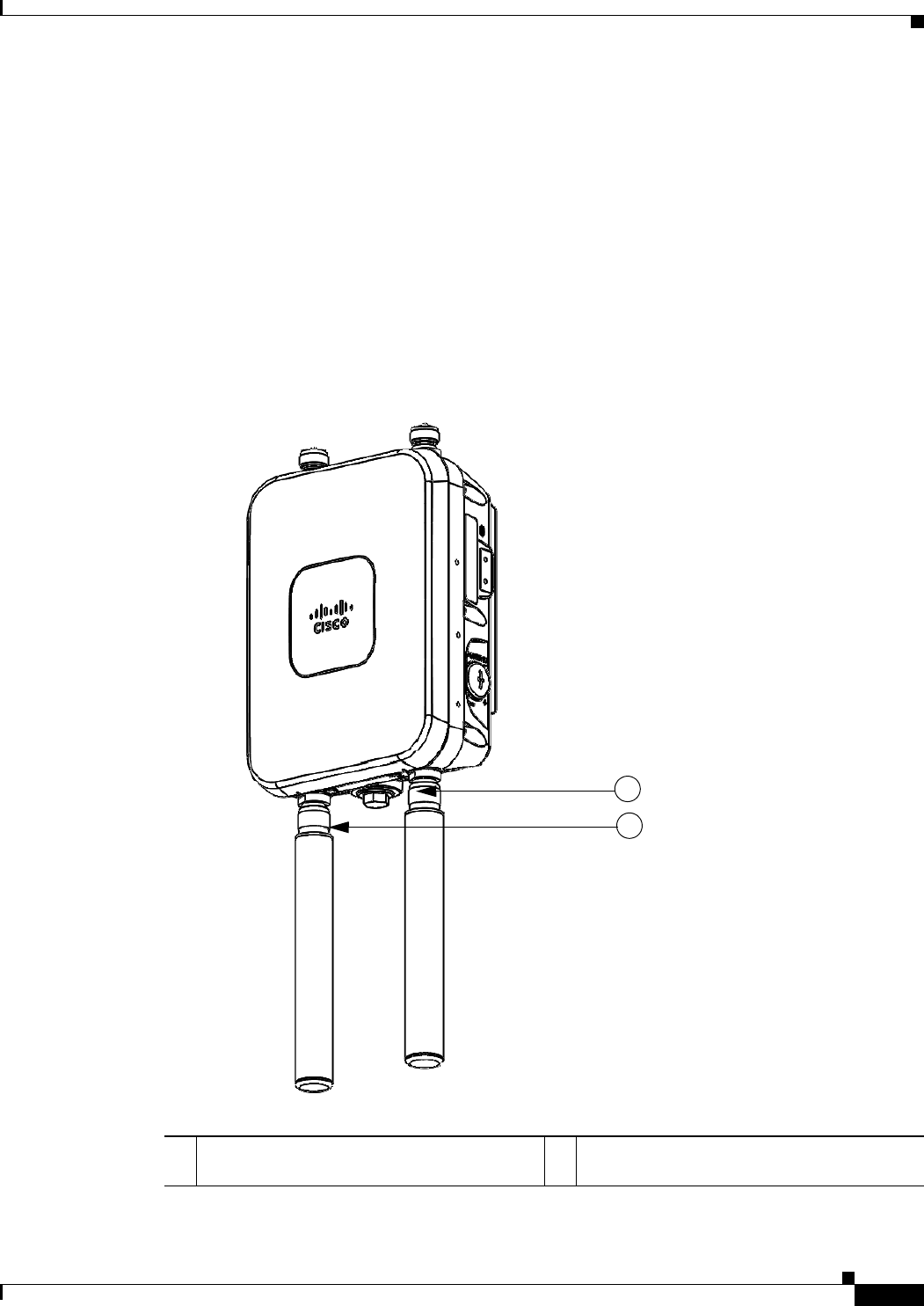
2-37
Cisco Aironet 1560 Series Outdoor Access Point Hardware Installation Guide
Chapter 2 Installing the Access Point
Installing Antennas
•Gain:
–
2400–2483 MHz — 4-dBi
–
5250–5875 MHz — 7-dBi
The antenna is designed to create an omnidirectional broadcast pattern. To achieve this pattern, mount
the access point clear of any obstructions to the sides of the radiating element.
For detailed information on this antenna, refer to the Cisco Aironet Dual-Band Omnidirectional Antenna
(AIR-ANT2547V-N, AIR-ANT2547VG-N) document. Follow all safety precautions when installing the
antennas. For information on safety, refer to “Safety Precautions when Installing Antennas” section on
page 2-35.
Figure 2-20 Cisco Aironet Dual-Band Omnidirectional Antenna - Installed Only on Model
AIR-AP1562E-x-K9
1Antenna connected to antenna port 1(Type-N
connector) (TX/RX)
2Antenna connected to antenna port 2(Type-N
connector) (TX/RX)
2
1
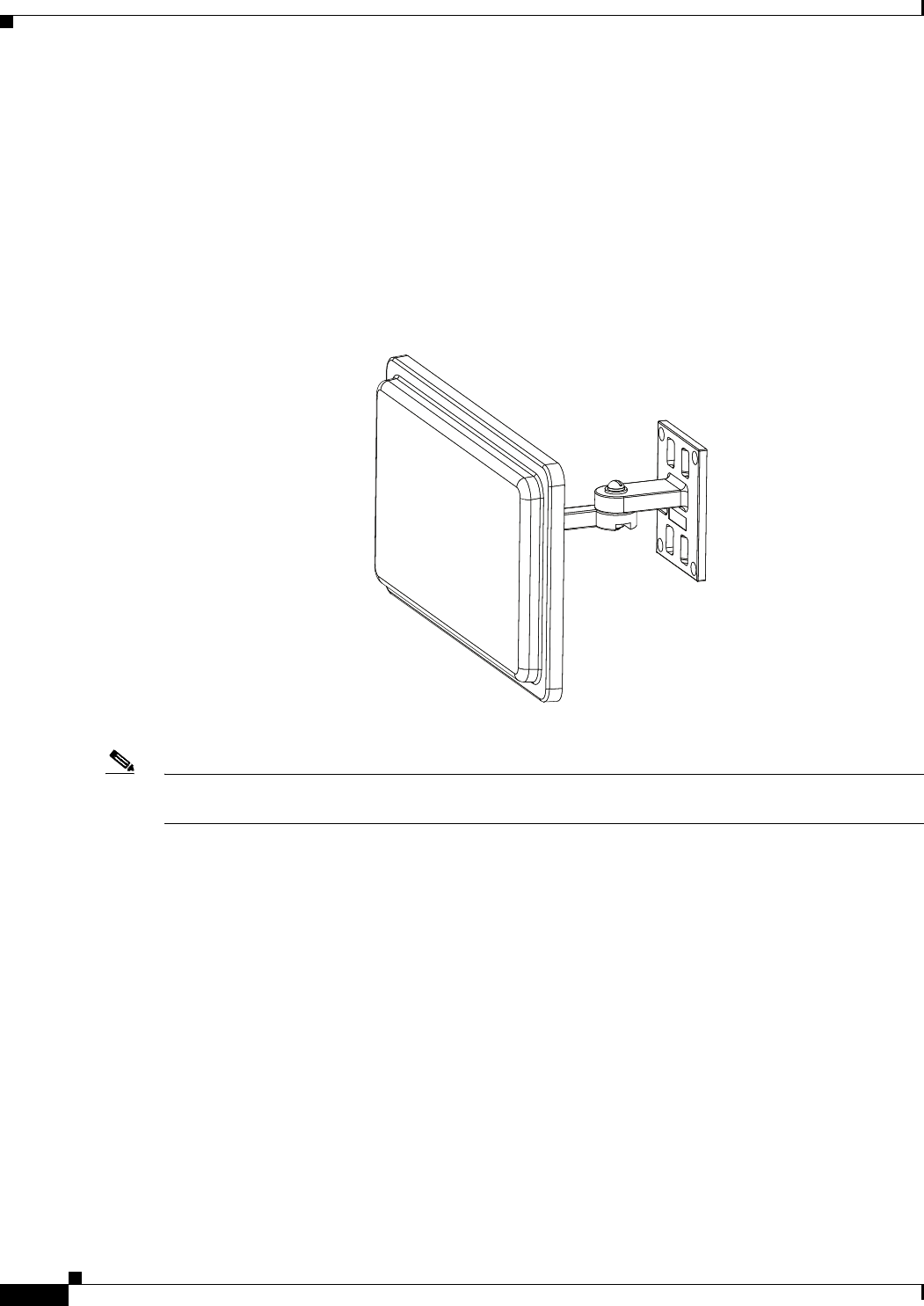
2-38
Cisco Aironet 1560 Series Outdoor Access Point Hardware Installation Guide
Chapter 2 Installing the Access Point
Installing Antennas
Cisco Aironet 2.4-GHz/5-GHz 8-dBi Directional Antenna (AIR-ANT2588P3M-N)
The Cisco Aironet 2.4-GHz/5-GHz 8-dBi Directional Antenna is designed for outdoor use with Cisco
Aironet Outdoor Access Points with radios operating in both the 2.4-GHz and 5-GHz frequency bands.
This antenna has 8-dBi gain in both bands.
For detailed information on this antenna, refer to the Cisco Aironet 2.4-GHz/5-GHz 8-dBi Directional
Antenna (AIR-ANT2588P3M-N) document. Follow all safety precautions when installing the antennas,
for information on safety, refer to “Safety Precautions when Installing Antennas” section on page 2-35.
Figure 2-21 Cisco Aironet 2.4-GHz/5-GHz 8-dBi Directional Antenna - Installed Only on Model
AIR-AP1562E-x-K9
Note When installing the AIR-ANT2588P3M-N with the Cisco Aironet 1560 Series AP, connect the
outermost antenna ports (marked ‘1’ in Figure 2-22) to the AP’s dual band antenna ports.
334574
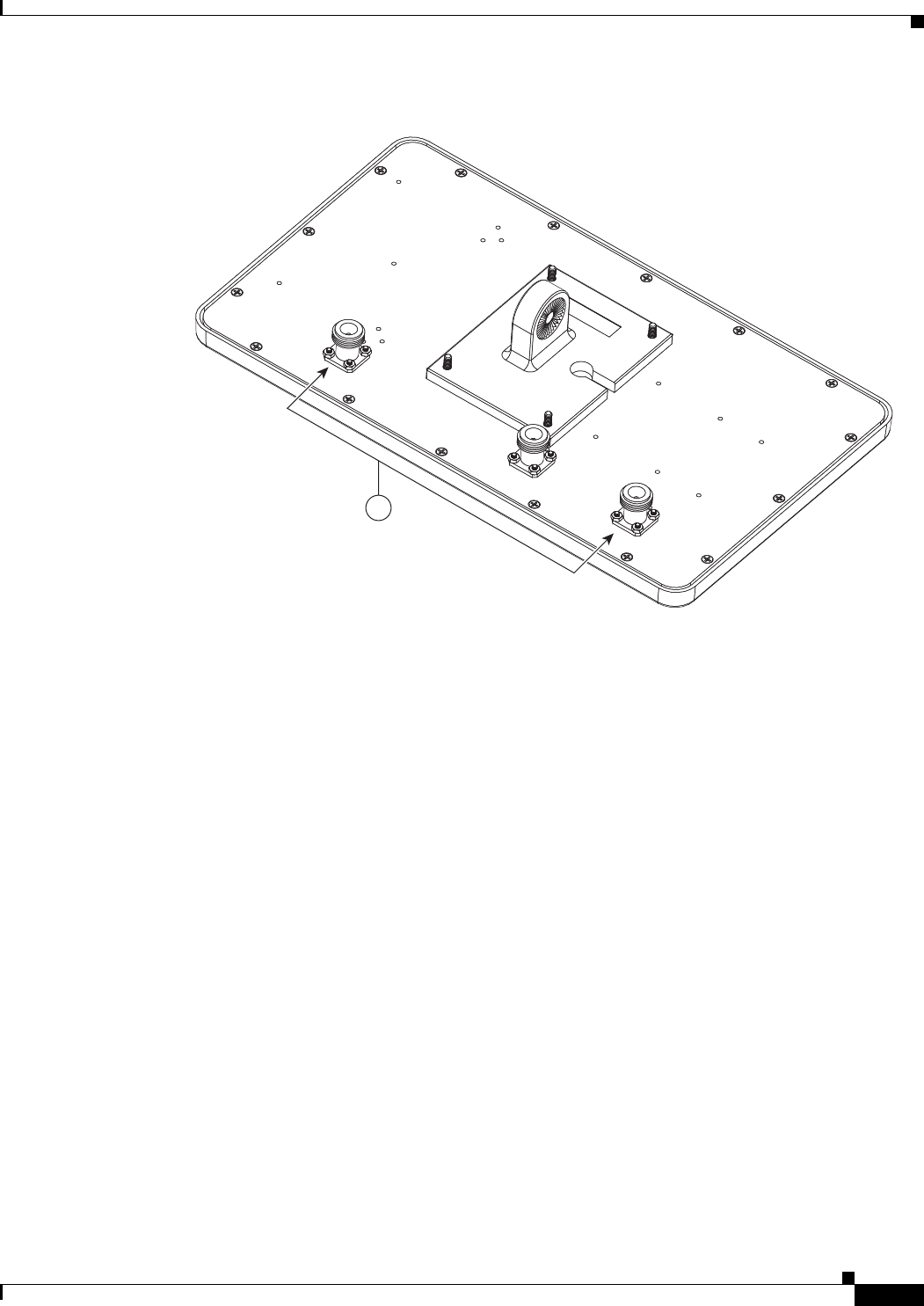
2-39
Cisco Aironet 1560 Series Outdoor Access Point Hardware Installation Guide
Chapter 2 Installing the Access Point
Installing Antennas
Figure 2-22 Antenna Ports For Connection to AP’s Dual Band Ports
1
352639
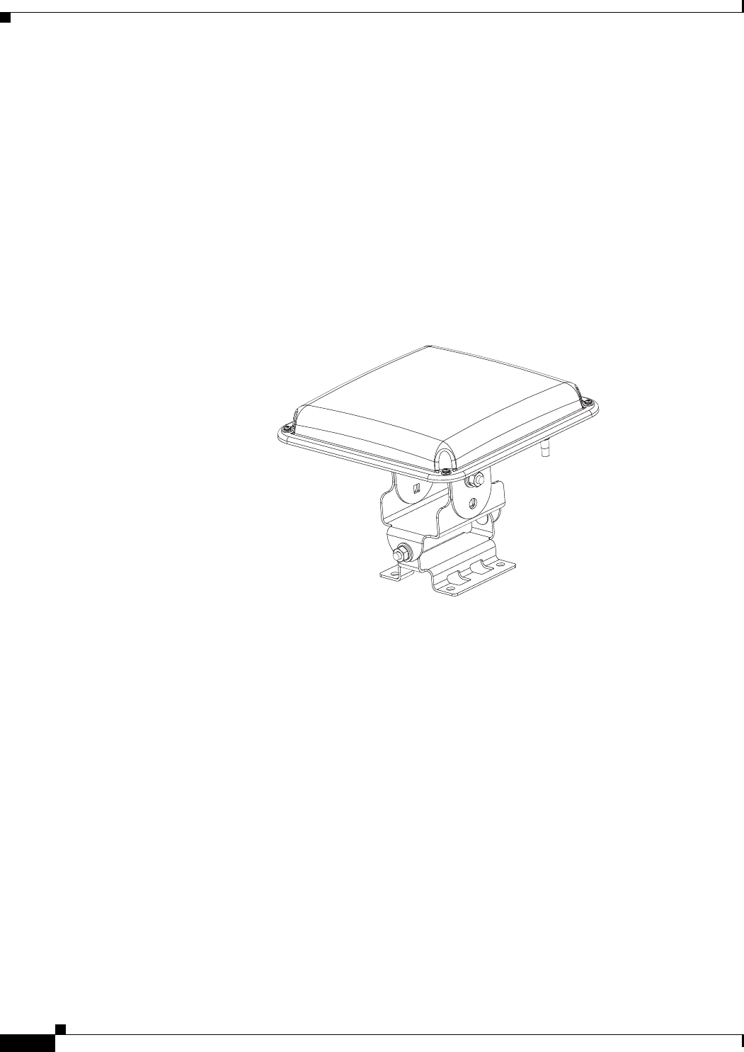
2-40
Cisco Aironet 1560 Series Outdoor Access Point Hardware Installation Guide
Chapter 2 Installing the Access Point
Installing Antennas
Cisco Aironet 5-GHz 14-dBi 2-Port Directional Antenna (AIR-ANT5114P2M-N)
The Cisco Aironet 5-GHz 14-dBi 2-Port Directional Antenna is designed for outdoor use with Cisco
Aironet Outdoor Access Points with radios operating in the 5-GHz frequency band. This antenna has
14-dBi in the 5-GHz band.
For more information, see the Cisco Aironet 5-GHz 14-dBi Directional Antenna document, at the
following URL:
http://www.cisco.com/c/en/us/td/docs/wireless/antenna/installation/guide/ant5114p2m-n.html.
For detailed information on this antenna, see the Cisco Aironet 5-GHz 14-dBi Directional Antenna
(AIR-ANT5114P2M-N) document. Follow all safety precautions when installing the antennas, for
information on safety, refer to “Safety Precautions when Installing Antennas” section on page 2-35.
Figure 2-23 Cisco Aironet 5-GHz 14-dBi Directional Antenna - Installed Only on Models
AIR-AP1562E-x-K9
334576
2-41
Cisco Aironet 1560 Series Outdoor Access Point Hardware Installation Guide
Chapter 2 Installing the Access Point
Installing Antennas
Cisco Aironet 2.4-GHz 13-dBi 2-Port Directional Antenna (AIR-ANT2413P2M-N)
The Cisco Aironet 2.4-GHz 13-dBi 2-Port Directional Antenna is designed for outdoor use with Cisco
Aironet Outdoor Access Points with radios operating in the 2.4-GHz frequency band. This antenna has
13-dBi gain in the 2.4-GHz frequency band.
For detailed information on this antenna, refer to the Cisco Aironet 2.4-GHz 13-dBi Directional Antenna
(AIR-ANT2413P2M-N) document. Follow all safety precautions when installing the antennas, for
information on safety, refer to “Safety Precautions when Installing Antennas” section on page 2-35.
Figure 2-24 Cisco Aironet 2.4-GHz 13-dBi Directional Antenna - Installed Only on Models
AIR-AP1562E-x-K9
334576
2-42
Cisco Aironet 1560 Series Outdoor Access Point Hardware Installation Guide
Chapter 2 Installing the Access Point
Installing Antennas
Cisco Aironet 2.4-GHz 5-dBi Omnidirectional Antenna (AIR-ANT2450V-N)
The Cisco Aironet 2.4-GHz 5-dBi Omnidirectional Antenna is designed for outdoor use with Cisco
Aironet Outdoor Access Points with radios operating in the 2.4-GHz frequency band. This antenna has
a 5-dBi gain in the 2.4-GHz band.
For detailed information on this antenna, refer to the document Cisco Aironet 5-dBI Omnidirectional
Antenna (AIR-ANT2450V-N). Follow all safety precautions when installing the antennas. For
information on safety, refer to “Safety Precautions when Installing Antennas” section on page 2-35.
Figure 2-25 Cisco Aironet 2.4-GHz 5-dBi Omni Antenna - Installed Only on Model
AIR-AP1562E-x-K9
231297
2-43
Cisco Aironet 1560 Series Outdoor Access Point Hardware Installation Guide
Chapter 2 Installing the Access Point
Installing Antennas
Cisco Aironet 2.4-GHz 8-dBi Omnidirectional Antenna (AIR-ANT2480V-N)
The Cisco Aironet 2.4-GHz 8-dBi Omnidirectional Antenna is designed for outdoor use with Cisco
Aironet Outdoor Access Points with radios operating in the 2.4-GHz frequency band. This antenna has
8-dBi gain in the 2.4-GHz frequency band.
For detailed information on this antenna, refer to the document Cisco Aironet 8-dBi Omnidirectional
Antenna (AIR-ANT2480V-N). Follow all safety precautions when installing the antennas, for information
on safety, refer to “Safety Precautions when Installing Antennas” section on page 2-35.
Figure 2-26 Cisco Aironet 2.4-GHz 8-dBi Omni Antenna - Installed Only on Model
AIR-AP1562E-x-K9i
230540
2-44
Cisco Aironet 1560 Series Outdoor Access Point Hardware Installation Guide
Chapter 2 Installing the Access Point
Installing Antennas
Cisco Aironet 5-GHz 8-dBi Omnidirectional Antenna (AIR-ANT5180V-N)
The Cisco Aironet 5-GHz 8-dBi Omnidirectional Antenna is designed for outdoor use with Cisco
Aironet Outdoor Access Points with radios operating in the 5-GHz frequency band. This antenna has
8-dBi gain in the 5-GHz frequency band.
For detailed information on this antenna, refer to the document Cisco Aironet 8-dBi Omnidirectional
Antenna (AIR-ANT5180V-N). Follow all safety precautions when installing the antennas, for information
on safety, refer to “Safety Precautions when Installing Antennas” section on page 2-35.
Figure 2-27 Cisco Aironet 5-GHz 8-dBi Omnidirectional Antenna - Installed Only on Model
AIR-AP1562E-x-K9
2-45
Cisco Aironet 1560 Series Outdoor Access Point Hardware Installation Guide
Chapter 2 Installing the Access Point
Installing Antennas
Using a Mounting Bracket for External Directional Antennas
You can use the AIR-ACCAMK-2= bracket for mounting a directional antenna directly on the access
point. See Figure 2-28.
Figure 2-28 Directional Antenna Mounting Bracket AIR-ACCAMK-2= Views
1Mounting holes for the directional antenna. 2Note the direction of the arrow. Ensure that
the bracket and AP are mounted with the
arrow pointing upwards.
3Slots to be used for managing the antenna
cables with cable ties.
4Two of four #8-32 screws and the mounting
points used to mount the bracket to the AP.
2-46
Cisco Aironet 1560 Series Outdoor Access Point Hardware Installation Guide
Chapter 2 Installing the Access Point
Installing Antennas
Antenna N-Type Connector Locations
The access point antenna N-type connectors are located on the top and the bottom of model
AIR-AP1562E-x-K9. The N-type connectors support variety of the Cisco Aironet antennas. For detailed
information on these antennas, refer to Antenna Configurations, page 2-36. Figure 2-29 shows the
antenna port locations viewed from the RF cover side.
Figure 2-29 Antenna Port Locations - Model AIR-AP1562E-x-K9
Installing a Lightning Arrestor
Overvoltage transients can be created through lightning static discharges, switch processes, direct
contact with power lines, or through earth currents. The Cisco Aironet AIR-ACC245LA-N Lightning
Arrestor limits the amplitude and duration of disturbing interference voltages and improves the over
voltage resistance of in-line equipment, systems, and components. A lightning arrestor installed
according to these mounting instructions balances the voltage potential, thus preventing inductive
interference to parallel signal lines within the protected system.
Installation Considerations
Cisco recommends that you bulkhead mount the lightning arrestor so it can be installed as a wall-feed
through on the wall of the protected space.
The importance of obtaining a good ground and bonding connection cannot be overstressed. Consider
these points when grounding the lightning arrestor:
1Antenna port 1 – Type N connector 2Antenna port 2- Type N connector
3Antenna port 3– Type N connector (with cap) 4Antenna port 4- Type N connector (with cap)
351321
1
34
2
2-47
Cisco Aironet 1560 Series Outdoor Access Point Hardware Installation Guide
Chapter 2 Installing the Access Point
Installing Antennas
•Connect the lightning arrestor components directly to the grounding point.
•The contact points of the ground connection must be clean and free of dust and moisture.
•Tighten threaded contacts to the torque specified by the manufacturer.
Installation Notes
This lightning arrestor is designed to be installed between the antenna cable that is attached to an outdoor
antenna and the Cisco Aironet wireless device. You can install the lightning arrestor either indoors or
outdoors. It can be connected directly to a wireless device having an external N connector. It can also be
mounted inline or as a feed-through. Feed-through installations require 5/8 in. (16 mm) hole to
accommodate the lightning arrestor.
Note This lightning arrestor is part of a lightning arrestor kit. The kit contains a lightning arrestor and a
grounding lug.
Note When you install the lightning arrestor, follow the regulations or best practices applicable to lightning
protection installation in your local area.
Installing the Lightning Arrestor Outdoors
If you install the lightning arrestor outdoors, use the supplied ground lug and a heavy wire (#6 solid
copper) to connect it to a good earth ground, such as a ground rod. The connection should be as short as
possible.
Figure 2-30 Lightning Arrestor Details
1Nut 4Unprotected side (to antenna)
2Lockwasher 5Protected side (to wireless device)
3Ground lug
1
2
3
4
5
346382

2-48
Cisco Aironet 1560 Series Outdoor Access Point Hardware Installation Guide
Chapter 2 Installing the Access Point
Grounding the Access Point
Cable for the Lightning Arrestor
Coaxial cable loses efficiency as the frequency increases, resulting in signal loss. The cable should be
kept as short as possible because cable length also determines the amount of signal loss (the longer the
run, the greater the loss).
Cisco recommends a high-quality, low-loss cable for use with the lightning arrestor.
Grounding the Access Point
The access point must be grounded before connecting power.
Warning
This equipment must be externally grounded using a customer-supplied ground wire before power is
applied. Contact the appropriate electrical inspection authority or an electrician if you are uncertain
that suitable grounding is available.
Statement 366
Warning
Installation of the equipment must comply with local and national electrical codes.
Statement 1074
In all outdoor installations and when powering the access point with AC power, you must follow these
instructions to properly ground the case:
Step 1 If using insulated 6-AWG copper ground wire, strip the insulation as required for the grounding lug.
Step 2 Use the appropriate crimping tool to crimp the bare 6-AWG copper ground wire to the supplied
grounding lug.
Note The grounding lug and hardware used must comply with local and national electrical codes.
Step 3 Open the anti-corrosion sealant (supplied), and apply a liberal amount over the metal surface where the
ground strap screw holes are located (see Figure 1-5).
Step 4 Connect the grounding lug to the access point grounding screw holes (see Figure 1-5) using the supplied
two Phillips head screws (M4 x10 mm) with lock washers. Tighten the grounding screw to
22 to 24 lb-in (2.49 to 2.71 Nm).
Step 5 If necessary, strip the other end of the ground wire and connect it to a reliable earth ground, such as a
grounding rod or an appropriate grounding point on a metal streetlight pole that is grounded (see
Figure 2-3).
2-49
Cisco Aironet 1560 Series Outdoor Access Point Hardware Installation Guide
Chapter 2 Installing the Access Point
Powering the Access Point
Powering the Access Point
Warning
Installation of the equipment must comply with local and national electrical codes.
Statement 1074
Warning
This equipment must be externally grounded using a customer-supplied ground wire before power is
applied. Contact the appropriate electrical inspection authority or an electrician if you are uncertain
that suitable grounding is available.
Statement 366
Warning
Do not work on the system or connect or disconnect cables during periods of lightning activity.
Statement 1001
The 1560 access point supports these power sources:
•DC power – 42- 57 VDC
•Power-over-Ethernet (PoE)
The 1560 access point can be powered via the PoE input from an in-line power injector or a suitably
powered switch port. Depending on the configuration and regulatory domain, the required power for full
operation is UPoE.
For the 1562I, UPoE powered switch port or a power injector is required for full operation of the 3x3
MIMO on the 2.4 GHz radio in the regulatory domains that allow for high 2.4 GHz transmit power
(Regulatory domains -A, -D, -F, -K, -N, -Q, -T, -Z). If the 1562I is powered by a PoE+ (802.3at power)
switch port then the access point will automatically disable one of the 2.4 GHz transmitters and the radio
will operate in 2x3 MIMO mode.
Table 2-9 AP 1560 Power Matrix
Model Configuration
Regulatory
Domain
Switch
Power
AIR-PWRINJ-60RGD1
AIR-PWRINJ-60RGD2
AIR-PWRINJ6
1AD/DC Power Adapter
AIR-PWRADPT-RGD1
1562I 3x3:3 (2.4 GHz) A, B, D, I,
K, N, Q, T,
Z
UPOE Yes No Yes
3x3:3 (5 GHz)
3x3:3 (2.4 GHz) C, E, F, G,
H, L, M, R,
S
UPOE (Will be added
at FCS)
3x3:3 (5 GHz)
2x2:2 (2.4 GHz) A, B, C, D,
E, F, G, H,
I,
K, L, M,
N, Q, R, S,
T, Z
802.3at
PoE+
Yes
2x2:2 (5 GHz)
1562D 2x2:2 (2.4 GHz) A, B, C, D,
E, F, G, H,
I, K, L, M,
N, Q, R, S,
T, Z
802.3at
PoE+
Yes Yes Yes
2x2:2 (5 GHz)
1562E 2x2:2 (2.4 GHz)
2x2:2 (5 GHz)
2-50
Cisco Aironet 1560 Series Outdoor Access Point Hardware Installation Guide
Chapter 2 Installing the Access Point
Powering the Access Point
Warning
Connect the unit only to DC power source that complies with the Safety Extra-Low Voltage (SELV)
requirements in IEC 60950 based safety standards
Statement 1033
Connecting a 1560 Series Power Injector
The 1560 Series Access Points support the following power injectors:
•AIR-PWRINJ-60RGD1
•AIR-PWRINJ-60RGD2
•AIR-PWRINJ-30RGD1
The power injector provides 56 VDC to the access point over the Ethernet cable and supports a total
end-to-end Ethernet cable length of 100 m (328 ft) from the switch to the access point.
When your access point is powered by an optional power injector, follow these steps to complete the
installation:
Step 1 Before applying PoE to the access point, ensure that the access point is grounded (see the “Grounding
the Access Point” section on page 2-48).
Step 2 Review Figure 2-2 to identify the components needed for the installation.
Step 3 Connect a CAT5e or better Ethernet cable from your wired LAN network to the power injector.
Warning
To reduce the risk of fire, use only No. 26 AWG or larger telecommunication line cord.
Statement 1023
Note The installer is responsible for ensuring that powering the access point from this type of power
injector is allowed by local and/or national safety and telecommunications equipment standards.
Tip To forward bridge traffic, add a switch between the power injector and controller. Refer to the
Cisco Wireless Mesh Access Points, Design and Deployment Guide, Release 7.0 for more
information.
Step 4 Ensure that the antennas are connected and that a ground is attached to the access point before you apply
power to the access point.
Step 5 Connect a shielded outdoor-rated Ethernet (CAT5e or better) cable between the power injector and the
PoE-in connector of the access point (see Figure 2-31).
Step 6 Connect the Ethernet cable to the access point PoE-In port (see “Connecting an Ethernet Cable to the
Access Point” section on page 2-51).
1. The AIR-PWRINJ6 power injector can only be used in an indoor environment. Therefore the cable from the injector must travel from the protected
location to the outside mounted access point.
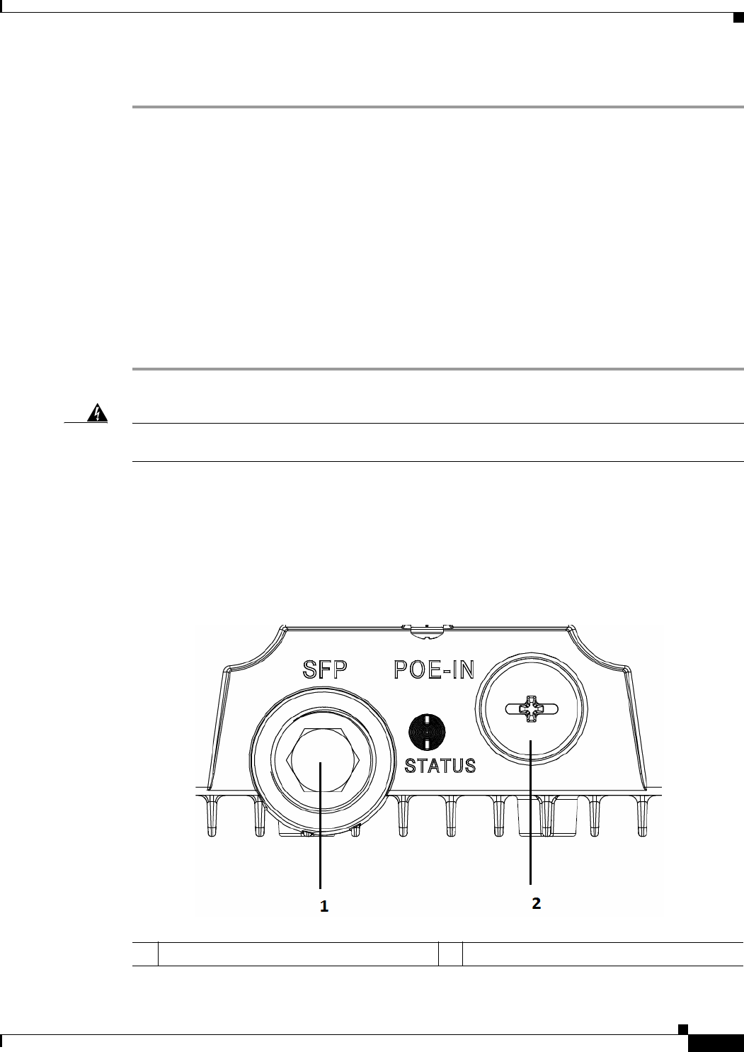
2-51
Cisco Aironet 1560 Series Outdoor Access Point Hardware Installation Guide
Chapter 2 Installing the Access Point
Powering the Access Point
Step 7 Continue with What to Do Next, page 2-66.
Connecting an Ethernet Cable to the Access Point
You need to supply these tools and materials:
•Shielded outdoor-rated Ethernet (CAT5e or better) cable with 0.2 to 0.35 in. (0.51 to 0.89 cm)
diameter
•RJ-45 connector and installation tool
•Adjustable Wrench or 28 mm box wrench
•Large Phillips or Flat Blade screwdriver
To connect the shielded Ethernet cable to the access point, follow these steps:
Step 1 Disconnect power to the power injector, and ensure all power sources to the access point are turned off.
Warning
This unit might have more than one power supply connection. All connections must be removed to
de-energize the unit.
Statement 1028
Step 2 Ensure a 6 AWG ground wire is connected to the access point (see the “Grounding the Access Point”
section on page 2-48).
Step 3 Use a large Phillips or Flat Blade screw driver to remove the Ethernet connector plug from the access
point. Do not discard plug and rubber seal unless you are certain that the port will not have to be
re-plugged (see Figure 2-31 for the location).
Figure 2-31 Access Point PoE-In Connector- AP 1562I
1SFP port (covered) 2PoE-In port (covered)
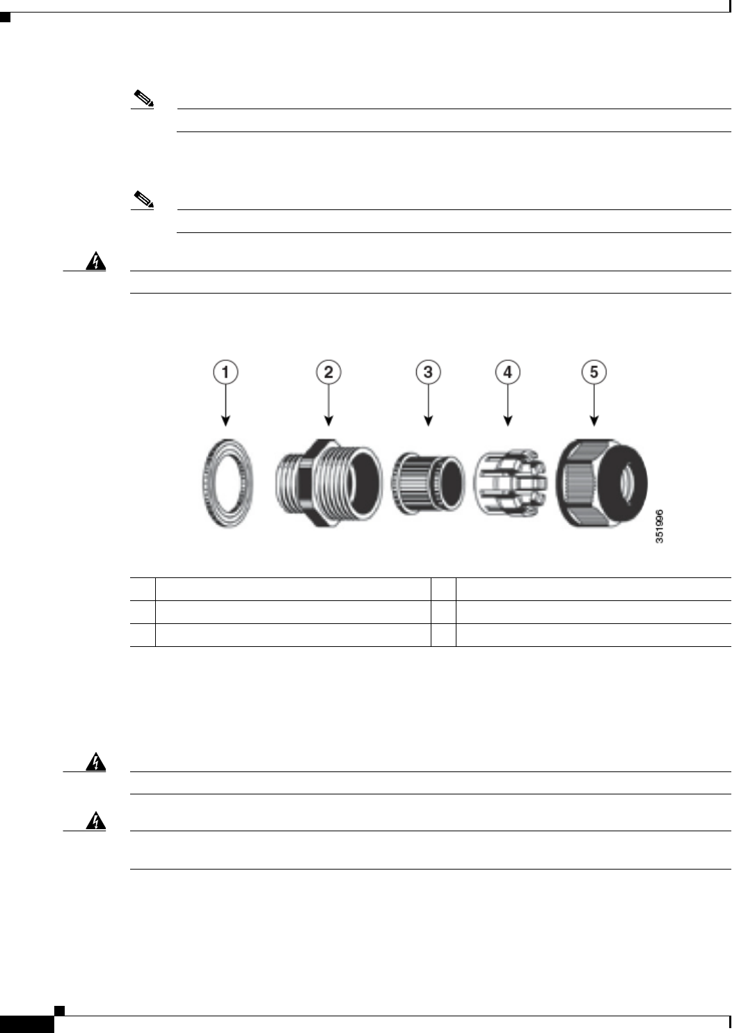
2-52
Cisco Aironet 1560 Series Outdoor Access Point Hardware Installation Guide
Chapter 2 Installing the Access Point
Powering the Access Point
Note For information on data cable entry, refer to Figure 1-1
Step 4 Loosen the Thread-Lock sealing nut of the cable gland by turning it counter clockwise, but do not
remove it (see Figure 2-32).
Note Verify that the cable gland has a rubber seal and ensure that it is not damaged.
Warning
Failure to install the cable gland and rubber gasket properly will cause the cable grip to leak.
Figure 2-32 Cable Gland
Step 5 Insert the unterminated end of the Ethernet cable through the sealing nut end of the cable gland (see
Figure 2-32), and pull several inches of cable through the adapter.
Step 6 Install an RJ-45 connector on the unterminated end of the Ethernet cable using your Ethernet cable
installation tool.
Warning
To reduce the risk of fire, use only No. 26 AWG or larger telecommunication line cord.
Statement 1023
Warning
When installing the RJ-45 connector, ensure that cable gland and the rubber gasket are present and
installed properly, to avoid water leakage into the enclosure. See Figure 2-32 and Figure 2-33.
Step 7 Carefully insert the RJ-45 cable connector into the Ethernet port opening on the access point, and
connect to the internal Ethernet connector (see Figure 2-33).
1Washer (Rubber Gasket) 2Body
3Sealing insert 4Clamping claw
5Thread-lock sealing nut
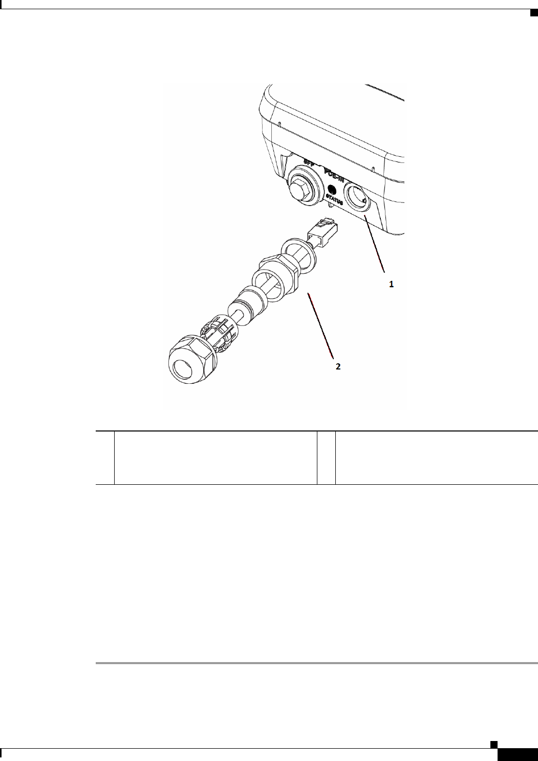
2-53
Cisco Aironet 1560 Series Outdoor Access Point Hardware Installation Guide
Chapter 2 Installing the Access Point
Powering the Access Point
Figure 2-33 Inserting RJ-45 Connector into the Ethernet Port Opening in Case
Step 8 Slide the cable gland with the rubber seal towards the access point, and screw the threaded end of the
body into the access point, and hand-tighten.
Step 9 Use an adjustable wrench or a 28-mm wrench to tighten the threaded end of the body into the enclosure.
Tighten to 15 lb-in.
Step 10 Use an adjustable wrench and tighten the thread-lock seal nut to 15 lb-in.
Step 11 Ensure that the antennas are connected to the access point before you apply power to the access point.
Step 12 Route your Ethernet cable, and cut off any excess cable.
Step 13 Install an RJ-45 connector on the unterminated cable end, and insert it into the power injector. For typical
installation components, see Figure 2-2.
Step 14 Turn on power to the power injector.
1Ethernet port opening in access point case. 2RJ-45 connector, on shielded outdoor-rated
Ethernet (CAT5e or better) cable (with an
exploded view of the cable gland, on the
Ethernet cable).
2-54
Cisco Aironet 1560 Series Outdoor Access Point Hardware Installation Guide
Chapter 2 Installing the Access Point
Powering the Access Point
Connecting a DC Power Cable to the Access Point
When powering the access point with DC power, you must ensure that DC power can be conveniently
removed from the unit. The power should not be removed by disconnecting the DC power connector on
the unit.
Warning
A readily accessible two-poled disconnect device must be incorporated in the fixed wiring.
Statement 1022
Warning
Connect the unit only to DC power source that complies with the safety extra-low voltage (SELV)
requirements in IEC 60950 based safety standards.
Statement 1033
To connect a DC power cable, you need to supply these tools and material:
•Shielded outdoor-rated DC power cable (minimum 18 AWG) with outside cable diameter of 0.20 to
0.35 inch (0.51 to 0.89 cm).
•Adjustable or open-end wrench
•Small flat screw driver
•Two-pin DC power connector (Cisco supplied)
To connect the DC power cable to the access point, follow these steps:
Step 1 Before connecting DC power to the access point, ensure that the ground is connected to the access point
(see the “Grounding the Access Point” section on page 2-48).
Step 2 Turn off all power sources to the access point, including the DC power source.
Warning
This unit might have more than one power supply connection. All connections must be removed to
de-energize the unit.
Statement 1028
Caution When installing DC power to the access point, always connect the access point end of the cable FIRST.
When removing the DC power connector, always disconnect the access point end of the cable LAST.
Step 3 Use a large Phillips or Flat Blade screw driver to remove the Ethernet connector plug from the access
point. Do not discard plug and rubber seal unless you are certain that the port will not have to be
re-plugged. (see Figure 2-34 for the location of the DC power connector).
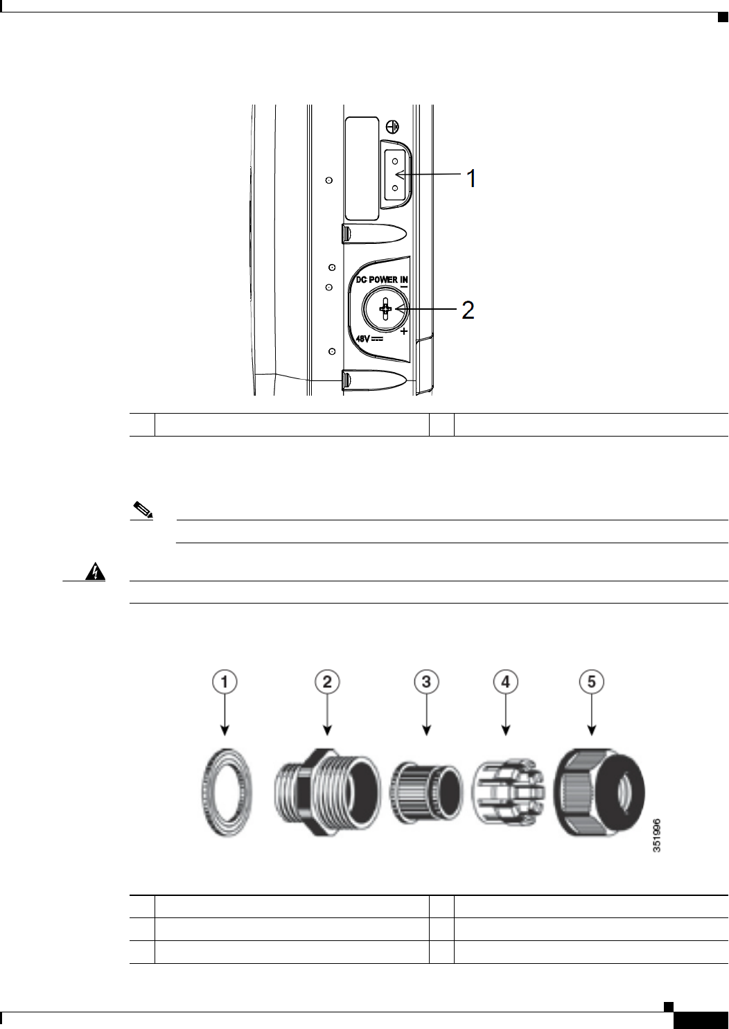
2-55
Cisco Aironet 1560 Series Outdoor Access Point Hardware Installation Guide
Chapter 2 Installing the Access Point
Powering the Access Point
Figure 2-34 Access Point DC Power Connector and Ground Lug on the Left of the AP
Step 4 Loosen the thread-lock sealing nut of the cable gland by turning it counter clockwise, but do not remove
it (see Figure 2-35).
Note Verify that the cable gland has a rubber seal and ensure that it is not damaged.
Warning
Failure to install the Cable Gland properly will cause the cable grip to leak.
Figure 2-35 Cable Gland
1DC power port 2Ground lug location
1Washer (Gasket) 2Body
3Sealing insert 4Clamping claw
5Thread-lock sealing nut
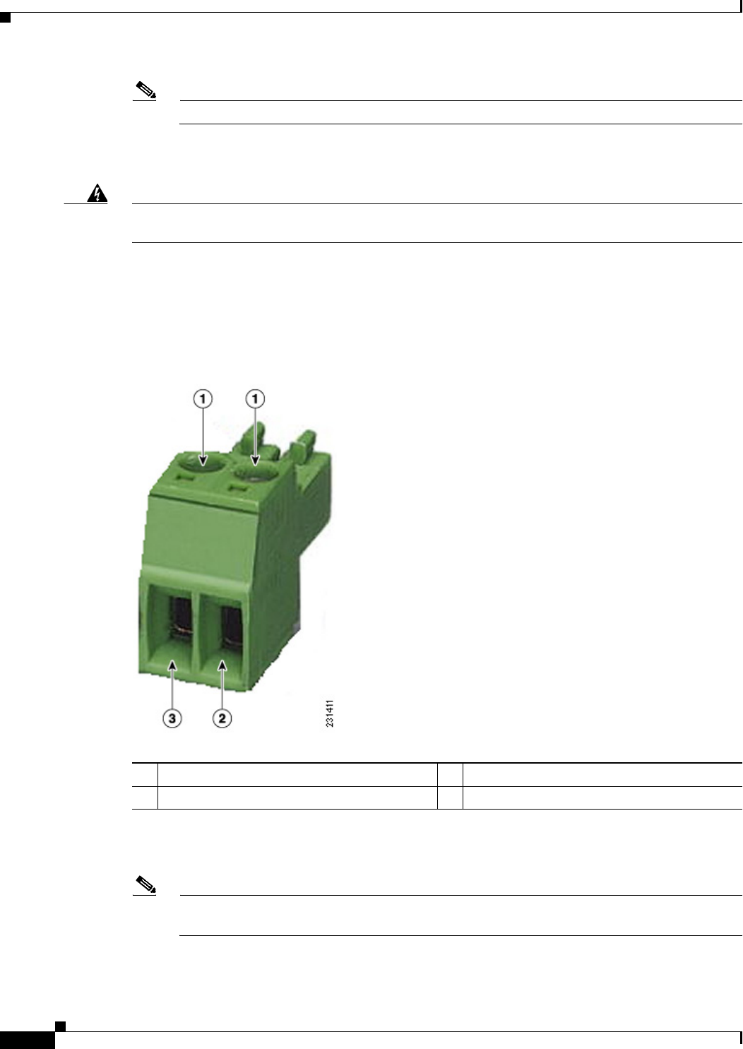
2-56
Cisco Aironet 1560 Series Outdoor Access Point Hardware Installation Guide
Chapter 2 Installing the Access Point
Powering the Access Point
Note The cable gland accepts a cable diameter of 0.20 to 0.35 in. (0.51 to 0.89 cm).
Step 5 Insert a bare end of the DC power cable into the rounded end of the cable gland (see Figure 2-35), and
pull approximately 6 inches of cable through the adapter.
Warning
When installing the DC power cable, ensure that cable gland and the rubber gasket are present and
installed properly, to avoid water leakage into the enclosure. See Figure 2-35 and Figure 2-37.
Step 6 Strip the DC cable jacket back about 1 inch to expose the wires and strip the insulation about 3/8 inch
(9.5 mm) from each wire.
Step 7 Insert each wire into the two-position terminal strip (supplied), and tighten each wire using a 0.1 inch
(0.25 cm) flat screw driver (see Figure 2-36).
Figure 2-36 Two-Position Terminal Strip
Step 8 Insert the two-position terminal strip into the DC power opening in the access point case, and carefully
push the terminal strip into the internal connector (see Figure 2-37).
Note Ensure that the polarity of the terminal strip properly matches the polarity markings on the
enclosure (see Figure 2-38)
1Securing screws 3Wire opening for DC +
2Wire opening for ground (DC return)
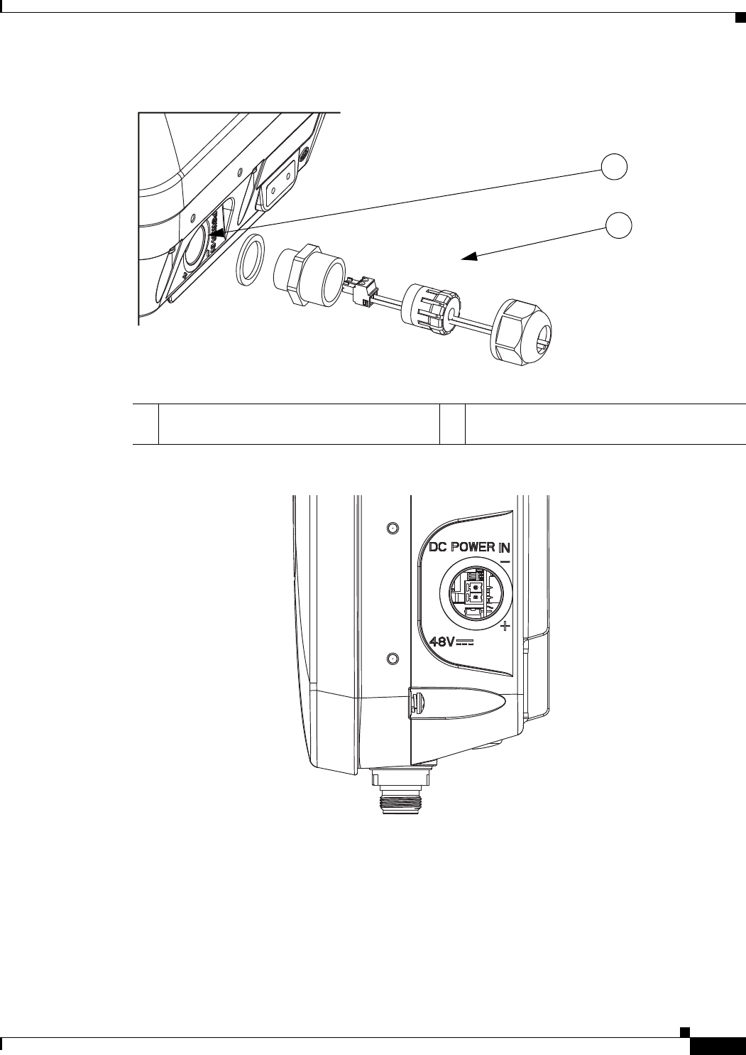
2-57
Cisco Aironet 1560 Series Outdoor Access Point Hardware Installation Guide
Chapter 2 Installing the Access Point
Powering the Access Point
Figure 2-37 Inserting the Terminal Strip into the DC Power Opening in the Access Point Case
Figure 2-38 DC Power Opening in the Access Point Case
Step 9 Slide the cable gland with the rubber seal towards the access point, and screw the threaded end of the
body into the access point, and hand-tighten.
Step 10 Use an adjustable wrench, a 28-mm wrench to tighten the threaded end of the body to 15 lb-in.
Step 11 Use an adjustable wrench and tighten the thread-lock seal nut to 15 lb-in.
Step 12 Ensure that the antennas are connected to the access point before you apply power to the access point.
Step 13 Turn on the DC power at the designated circuits.
1DC power opening in access point case. Also
see Figure 2-38.
2Exploded view of the cable gland on the DC
power cable
352057
1
2
352054
2-58
Cisco Aironet 1560 Series Outdoor Access Point Hardware Installation Guide
Chapter 2 Installing the Access Point
Powering the Access Point
Connecting Streetlight AC Power
The access point can be installed on a streetlight pole and powered from a streetlight outdoor light
control using the optional streetlight power tap adapter and AC/DC power adapter,
AIR-PWRADPT-RGD1=.
The AC/DC power adapter is used inline from the street light tap to the 1560 DC connector. The AC
power tap only can be used with the AC/DC power adapter.
When powering the access point with AC power other than the streetlight power tap adapter, you must
ensure that the following conditions are observed:
1. AC power can be conveniently removed from the unit. The power should not be removed by
disconnecting the AC power connector on the unit.
Warning
A readily accessible two-poled disconnect device must be incorporated in the fixed wiring.
Statement 1022
Caution Before connecting or disconnecting a power cord, you must remove AC power from the power cord using
a suitable service disconnect.
2. You must protect any AC power plugs and AC receptacles from water and other outdoor elements.
You can use a UL-listed waterproofing enclosure suitable for covering the AC receptacle and AC
power plug that supplies power to the unit as described in Article 406 of the NEC.
3. When you install the access point outdoors or in a wet or damp location, the AC branch circuit that
powers the access point should have ground fault protection (GFCI), as required by Article 210 of
the National Electrical Code (NEC).
Warning
Be very careful when connecting the streetlight adapter to Category 3 pole-top power. If you are not
careful, you may electrocute yourself or fall.
Statement 363
To install an access point on a streetlight pole, follow these steps:
Step 1 Before beginning the installation, ensure the AC power to the streetlight pole is turned off.
Step 2 Turn off power to the AC power source at the designated circuits.
Warning
This unit might have more than one power supply connection. All connections must be removed to
de-energize the unit.
Statement 1028
Caution For your safety, when connecting the access point AC power connector, always connect the access point
end of the cable FIRST. When removing the AC power connector, always disconnect the access point
end of the cable LAST.
Step 3 When using the streetlight power tap adapter, ensure that the access point is mounted within 3 feet (1 m)
of the outdoor light control.
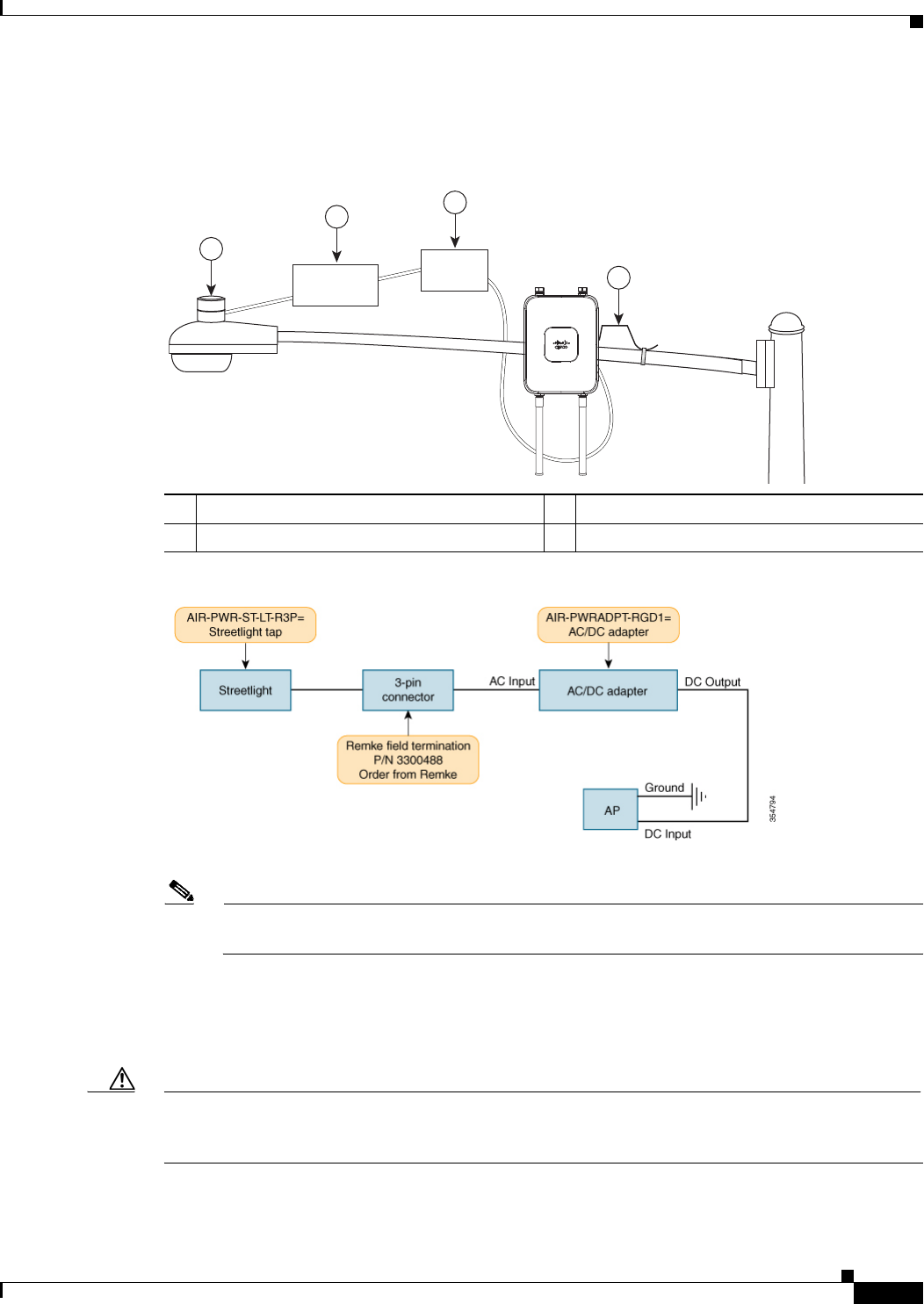
2-59
Cisco Aironet 1560 Series Outdoor Access Point Hardware Installation Guide
Chapter 2 Installing the Access Point
Powering the Access Point
Step 4 Ensure that a 6-AWG ground wire is attached to the access point (see Figure 2-39) and connected to the
streetlight pole (for instructions see Grounding the Access Point, page 2-48).
Figure 2-39 Using the Streetlight Power Tap Adapter
Figure 2-40 Components of the Streetlight Deployment
Note Deployment of the AP as shown in the streetlight deployment in Figure 2-39 requires an
alternate AP mounting kit. See Mounting the Access Point section for more information.
Step 5 Disconnect the outdoor light control from its fixture.
Step 6 Turn off power to the fixture at the designated circuits.
Caution When installing the streetlight power tap adapter to the access point AC power connector, always
connect the access point end of the cable FIRST. When removing the streetlight power tap adapter,
always disconnect the access point end of the cable LAST.
2
1
3
4
AC/DC
Adapter
2
Field
Te r m i n ation
1Outdoor light control 3AC/DC power adapter
2Field termination 46-AWG copper grounding wire
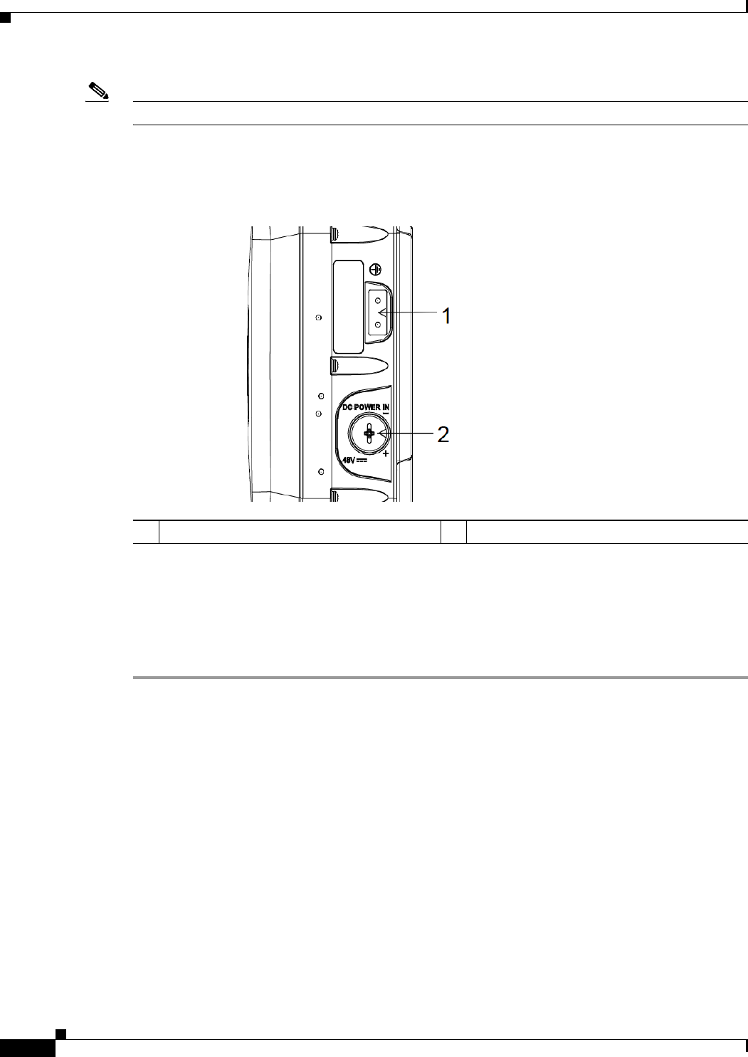
2-60
Cisco Aironet 1560 Series Outdoor Access Point Hardware Installation Guide
Chapter 2 Installing the Access Point
Connecting a Fiber-optic Cable to the AP
Note Ensure that your antennas are connected to the access point before you apply power to the access point.
Step 7 Connect the streetlight power tap adapter to the access point AC/DC power adapter. See Connecting a
Fiber-optic Cable to the AP.
Figure 2-41 Access Point DC Power Connector and Ground Lug on the Left of the AP
Step 8 Plug the streetlight power tap adapter into the outdoor light control fixture, as shown in Figure 2-39.
Step 9 Plug the outdoor light control into the streetlight power tap adapter.
Step 10 Ensure that the antennas are connected to the access point before you apply power to the access point.
Step 11 Turn on the power to the outdoor light control fixture at the designated circuits.
Connecting a Fiber-optic Cable to the AP
The Cisco supplied fiber-optic kit enables the access point to support fiber-optic network connections.
Your require the following materials for connecting the fiber-optic cable to the AP:
•Small form-factor pluggable (SFP) transceiver module
•SFP module adapter
•SC or Duplex LC fiber-optic cables. The outer diameter of the fiber optic cable should be 0.24-0.47
inches (6-12 mm).
•Cable gland. The cable gland cannot hold a cable with diameter more than 0.47” (12 mm).
•Adjustable wrench
1DC power port 2Ground lug location

2-61
Cisco Aironet 1560 Series Outdoor Access Point Hardware Installation Guide
Chapter 2 Installing the Access Point
Connecting a Fiber-optic Cable to the AP
You can connect the fiber-optic networking cable to the SFP port (labeled '4' on the base of the AP). The
small form-factor pluggable (SFP) transceiver module is used to connect the cable to the SFP port. The
SFP port provides both Power-over-Cable and backhaul over fiber options. To install the SFP transceiver
module and the cable, follow this procedure:
Step 1 Ensure that all power sources have been disconnected from the access point.
Step 2 Remove the covering plug from the SFP port by following the guidelines given in this step.
The SFP port covering plug is designed to be removed only once, and then be replaced with the SFP
adapter. The plug does not have a rubber O-ring, but is fixed in place using a sealant on the threads at
manufacturing. While removing the plug, you need to ensure that its hex bolt-head does not get stripped.
For this:
a. Place the AP on it's back (resting on the heat fins) on a solid, but padded surface, to avoid scratching
the paint.
b. Pressing down with your hand on the face of the AP and holding the AP firmly in place, proceed to
the next step.
c. Use a 5/8” (16 mm) 6-point socket wrench to loosen the hex bolt-head SFP port plug. Firmly and
carefully, turn the socket wrench counter-clockwise to loosen the plug. This requires a torque of
25 ft-lb (34 Nm).
Though not ideal, a 5/8” (16 mm) 12-point socket wrench can be used too. A crescent wrench is to
be used only if the socket wrenches are not available. Do not use a pipe or monkey wrench for this
task, as it will strip the hex bolt-head.
Step 3 Insert the SFP module into the SFP port, and ensure that it latches properly.
Step 4 Loosen the cable gland’s nut (round end of the cable gland) by turning counterclockwise, but do not
remove.
Step 5 Thread the fiber optic cable, from its unterminated end, into the cable gland. See Figure 2-42 and
Figure 2-43.
Thread the cable through the gland all the way till the gland is near the SC or LC optic fiber connectors.
The cable gland’s nut must remain loose at this time.
Note The SC or LC optic fiber connectors are too big to pass through the cable gland. That is the reason why
you need to thread the cable through the gland from the unterminated end (even if the cable is quite long).
Step 6 Insert the SC or LC optic fiber connector-end of the cable, into the SFP module adapter. Do not attach
the cable gland to the adapter yet. See Figure 2-44.
Step 7 Insert the SC or LC optic fiber connector into the SFP module and ensure that it latches into place. See
Figure 2-44.
Step 8 Add sealant or tape around the adapter's pipe thread, and then it screw into the AP chassis.
Step 9 Keeping the cable gland nut loose, carefully screw the threaded end of the cable gland into the SFP
module adapter and hand-tighten. Use an adjustable wrench to tighten the threaded end of the cable
gland to 6-7 lb.ft (8.1 to 9.5 Nm).
Step 10 Tighten the cable gland nut until it is properly fastened around the fiber optic cable. Use an adjustable
or open-end wrench to tighten to 2.7 to 3.2 lb.ft (3.66 to 4.34 Nm).
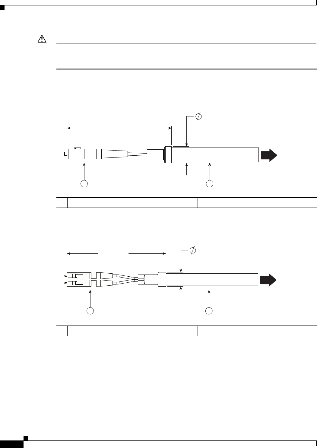
2-62
Cisco Aironet 1560 Series Outdoor Access Point Hardware Installation Guide
Chapter 2 Installing the Access Point
Connecting a Fiber-optic Cable to the AP
Caution When removing this SFP assembly it is absolutely imperative that you proceed in the reverse order of
this installation. Start by loosening the cable gland's nut.
Figure 2-42 SC Fiber-optic cable
Figure 2-43 Duplex LC Fiber Optic Cable
3.00" MAX
.475" MAX
353684
This end goes into
the cable gland
1 2
1SC optic fiber connector 2Optic fiber cable
3.35" MAX .475" MAX
353685
This end goes into
the cable gland
1 2
1Duplex LC optic fiber connector 2Optic fiber cable
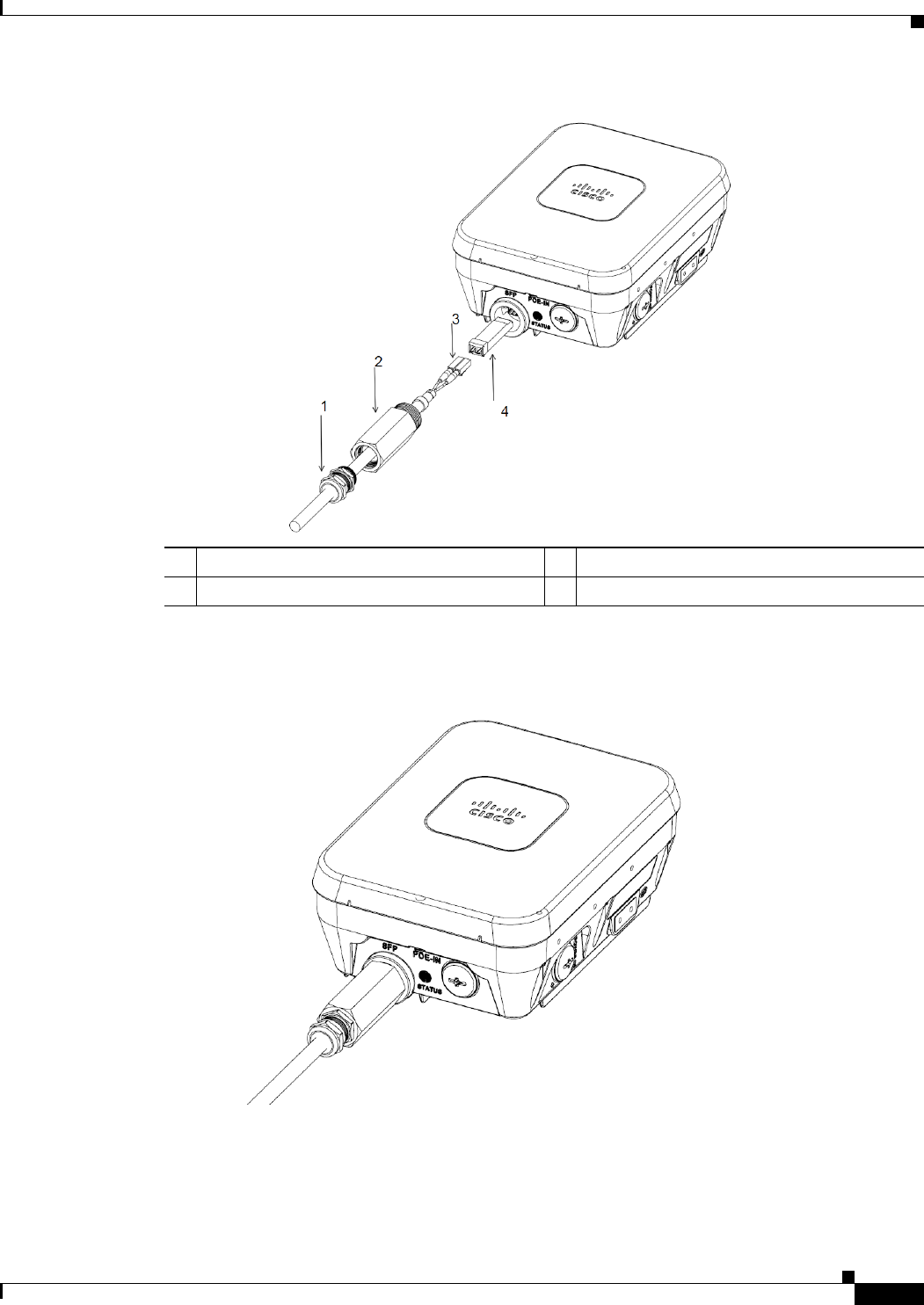
2-63
Cisco Aironet 1560 Series Outdoor Access Point Hardware Installation Guide
Chapter 2 Installing the Access Point
Connecting a Fiber-optic Cable to the AP
Figure 2-44 Exploded View of Connecting Fiber-optic Cable to AP
Figure 2-45 Fiber-optic Cable Successfully Connected to AP
1Cable gland 3Duplex LC Fiber-optic cable
2SFP module adapter 4SFP transceiver module

2-64
Cisco Aironet 1560 Series Outdoor Access Point Hardware Installation Guide
Chapter 2 Installing the Access Point
Configuring the Access Point
Configuring the Access Point
For information on configuring the access point, see the following documents:
•For Lightweight Access Points and Mesh Access Points, see the Cisco Wireless LAN Controller
Configuration Guide, which is available at:
(URL to be added at FCS)
•For Mesh Access Points, see the Cisco Wireless Mesh Access Points, Design and Deployment Guide,
which is available at:
(URL to be added at FCS)
•For Access Points in autonomous mode, see the Cisco Aironet Access Points Configuration Guide
for Cisco IOS Software, which is available at:
(URL to be added at FCS)

2-65
Cisco Aironet 1560 Series Outdoor Access Point Hardware Installation Guide
Chapter 2 Installing the Access Point
What to Do Next
What to Do Next
When you power up a MAP that is not connected to a wired Ethernet, fiber-optic, or cable network to
the controller, the access point uses the Cisco Adaptive Wireless Path Protocol (AWPP) to bind to
another mesh access point (MAP) with the best path to a root access point (RAP) connected to the wired
network to a controller. The access point sends a discovery request when powered up. If you have
configured the access point in the controller correctly, the controller sends back a discovery response to
the access point. When that happens, the access point sends out a join request to the controller, and the
controller responds with a join confirmation response. Then the access point establishes a Control And
Provisioning of Wireless Access Points (CAPWAP) connection to the controller and gets the shared
secret configured on the controller.
Refer to the Cisco Wireless LAN Controller Configuration Guide for more information on configuring,
monitoring, and operating your access points.

2-66
Cisco Aironet 1560 Series Outdoor Access Point Hardware Installation Guide
Chapter 2 Installing the Access Point
What to Do Next

CHAPTER
3-1
Cisco Aironet 1560 Series Outdoor Access Point Hardware Installation Guide
3
Troubleshooting
This chapter provides troubleshooting procedures for basic problems with the access point. For the most
up-to-date, detailed troubleshooting information, refer to the Cisco Technical Support and
Documentation website at the following URL:
http://www.cisco.com/cisco/web/support/index.html
Sections in this chapter include:
•Guidelines for Using the Access Points, page 3-2
•Controller MAC Filter List, page 3-3
•Using DHCP Option 43, page 3-3
•Monitoring the Access Point LEDs, page 3-4
•Verifying Controller Association, page 3-6
•Changing the Bridge Group Name, page 3-7
•Access Point Power Injector, page 3-7
•Accessing the Console Port and the Reset Button, page 3-7

3-2
Cisco Aironet 1560 Series Outdoor Access Point Hardware Installation Guide
Chapter 3 Troubleshooting
Guidelines for Using the Access Points
Guidelines for Using the Access Points
You should keep these guidelines in mind when you use the access points:
•The access point only supports Layer 3 CAPWAP communications with the controllers.
In Layer 3 operation, the access point and the controller can be on the same or different subnets. The
access point communicates with the controller using standard IP packets. A Layer 3 access point on
a different subnet than the controller requires a DHCP server on the access point subnet and a route
to the controller. The route to the controller must have destination UDP ports 12222 and 12223 open
for CAPWAP communications. The route to the primary, secondary, and tertiary controllers must
allow IP packet fragments.
•Before deploying your access points, ensure that the following has been done:
–
Your controllers are connected to switch ports that are configured as trunk ports.
–
Your access points are connected to switch ports that are configured as untagged access ports.
–
A DHCP server is reachable by your access points and has been configured with Option 43.
Option 43 provides the IP addresses of the management interfaces of your controllers. Typically,
a DHCP server can be configured on a Cisco switch.
–
Optionally, a DNS server can be configured to enable CISCO-CAPWAP-CONTROLLER. Use
local domain to resolve to the IP address of the management interface of your controller.
–
Your controllers are configured and reachable by the access points.
–
Your controllers are configured with the access point MAC addresses and the MAC filter list is
enabled.
–
Your switch must forward DHCP requests.
•After the access points are associated to the controller, you should change the bridge group name
(BGN) from the default value. With the default BGN, the mesh access points (MAPs) can potentially
try to connect with other mesh networks and slow down the convergence of the network.
Important Notes
Convergence Delays
During deployment, the access points can experience convergence delays due to various causes. The
following list identifies some operating conditions that can cause convergence delays:
•A root access point (RAP) attempts to connect to a controller using any of the wired ports (cable,
fiber-optic, PoE-in). If the wired ports are operational, the RAP can potentially spend several
minutes on each port prior to connecting to a controller.
•If a RAP is unable to connect to a controller over the wired ports, it attempts to connect using the
wireless network. This results in additional delays when multiple potential wireless paths are
available.
•If a MAP is unable to connect to a RAP using a wireless connection, it then attempts to connect using
any available wired port. The access point can potentially spend several minutes for each connection
method, before attempting the wireless network again.

3-3
Cisco Aironet 1560 Series Outdoor Access Point Hardware Installation Guide
Chapter 3 Troubleshooting
Controller MAC Filter List
Bridge Loop
The access point supports packet bridging between wired and wireless network connections. The same
network must never be connected to multiple wired ports on an access point or on two bridged access
points. A bridge loop causes network routing problems.
Controller DHCP Server
The controller DHCP server only assigns IP addresses to lightweight access points and wireless clients
associated to an access point. It does not assign an IP address to other devices, including Ethernet
bridging clients on the mesh access points.
MAP Data Traffic
If the signal on the access point backhaul channel has a high signal-to-noise ratio, it is possible for a
MAP to connect to the controller, via parent node, but not be able to pass data traffic, such as pinging
the access point. This can occur because the default data rate for backhaul control packets is set to 6
Mb/s, and the backhaul data rate set to auto by the user.
Controller MAC Filter List
Before activating your access point, you must ensure that the access point MAC address has been added
to the controller MAC filter list and that Mac Filter List is enabled.
Note The access point MAC address and barcode is located on the bottom of the unit. When two MAC
addresses are shown, use the top MAC address.
To view the MAC addresses added to the controller MAC filter list, you can use the controller CLI or the
controller GUI:
•Controller CLI—Use the show macfilter summary controller CLI command to view the MAC
addresses added to the controller filter list.
•Controller GUI—Log into your controller web interface using a web browser, and choose
SECURITY > AAA > MAC Filtering to view the MAC addresses added to the controller filter list.
Using DHCP Option 43
You can use DHCP Option 43 to provide a list of controller IP addresses to the access points, enabling
the access point to find and join a controller. Refer to the product documentation for your DHCP server
for instructions on configuring DHCP Option 43. For additional information, refer to the “Configuring
DHCP Option 43” section on page F-1.
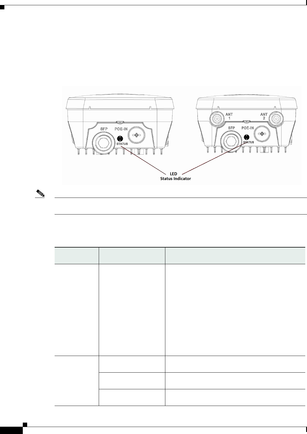
3-4
Cisco Aironet 1560 Series Outdoor Access Point Hardware Installation Guide
Chapter 3 Troubleshooting
Monitoring the Access Point LEDs
Monitoring the Access Point LEDs
If your access point is not working properly, look at the LEDs on the bottom of the unit. You can use
them to quickly assess the status of the unit. Figure 3-1 shows the location of the access point LEDs.
Figure 3-1 Access Point Status LED
Note It is expected that there will be small variations in LED color intensity and hue from unit to unit. This is
within the normal range of the LED manufacturer specifications and is not a defect.
The access point LED signals are listed in Table 3-1.
Table 3-1 Access Point LED Signals
LED Message
Type
Color Meaning
Boot loader
status sequence
Blinking Green Boot loader status sequence:
•DRAM memory test in progress
•DRAM memory test OK
•Board initialization in progress
•Initializing FLASH file system
•FLASH memory test OK
•Initializing Ethernet
•Ethernet OK
•Starting Cisco IOS
•Initialization successful
Boot loader
warnings
Blinking Amber Configuration recovery is in progress (the MODE button
has been pushed for 2-3 seconds)
Red There is an Ethernet failure or an image recovery (the
MODE button has been pushed for 20-30 seconds)
Blinking Green An image recovery is in progress (the MODE button has
been released)

3-5
Cisco Aironet 1560 Series Outdoor Access Point Hardware Installation Guide
Chapter 3 Troubleshooting
Monitoring the Access Point LEDs
Boot loader
errors
Red There has been a DRAM memory test failure
Blinking Red and Amber There has been a FLASH file system failure
Blinking Red and Off This sequence may indicate any of the following:
•Environment variable failure
•Bad MAC address
•Ethernet failure during image recovery
•Boot environment failure
•No Cisco image file
•Boot failure
Cisco IOS
errors
Red There has been a software failure; a disconnect then
reconnect of the unit power may resolve the issue
Cycling through Red,
Green, Amber and Off
This is a general warning of insufficient inline power.
Association
status
Chirping (short blips)
Green
This status indicates a normal operating condition. The
unit is joined to a controller, but no wireless client is
associated with it.
Solid Green Normal operating condition with at least one wireless
client associated with the unit
Operating
Status
Blinking Amber A software upgrade is in progress
Cycling through Green,
Red and Amber
Discovery/join process is in progress
Rapidly cycling through
Red, Green, Amber and
Off
This status indicates that the Access Point location
command has been invoked.
Blinking Red This status indicates that an Ethernet link is not
operational
Alignment
Mode
Color Signal Level (dBm)
Solid Green > –44
Fast blinking Green –47 to –44
Medium blinking Green –50 to –47
Solid Amber –53 to –50
Fast blinking Amber –57 to –53
Medium blinking Amber –60 to –57
Slow blinking Amber –63 to –60
Slow blinking Red –66 to –63
Medium blinking Red –69 to –66
Fast blinking Red –72 to –69
Solid Red –75 to –72
Off < –75
LED Message
Type
Color Meaning

3-6
Cisco Aironet 1560 Series Outdoor Access Point Hardware Installation Guide
Chapter 3 Troubleshooting
Verifying Controller Association
Verifying Controller Association
To verify that your access point is associated to the controller, follow these steps:
Step 1 Log into your controller web interface using a web browser.
You can also use the controller CLI show ap summary command from the controller console port.
Step 2 Click Wireless, and verify that your access point MAC address is listed under Ethernet MAC.
Step 3 Log out of the controller, and close your web browser.

3-7
Cisco Aironet 1560 Series Outdoor Access Point Hardware Installation Guide
Chapter 3 Troubleshooting
Changing the Bridge Group Name
Changing the Bridge Group Name
The bridge group name (BGN) controls the association of the access points to a RAP. BGNs can be used
to logically group the radios to avoid different networks on the same channel from communicating with
each other. This setting is also useful if you have more than one RAP in your network in the same area.
If you have two RAPs in your network in the same area (for more capacity), we recommend that you
configure the two RAPs with different BGNs and on different channels.
The BGN is a string of ten characters maximum. A factory-set bridge group name (NULL VALUE) is
assigned during manufacturing. It is not visible to you, but allows new access point radios to join a
network of new access points. The BGN can be reconfigured from the Controller CLI and GUI. After
configuring the BGN, the access point reboots.
After the access points are deployed and associated to the controller, the BGN should be changed from
the default value to prevent the MAPs from attempting to associate to other mesh networks.
The BGN should be configured very carefully on a live network. You should always start with the most
distant access point (last node) from the RAP and move towards the RAP. If you start configuring the
BGN in a different location, then the access points beyond this point (farther away) are dropped, as they
have a different BGN.
To configure the BGN for the access points using the controller GUI, follow these steps:
Step 1 Log into your controller using a web browser.
Step 2 Click Wireless. When access points associates to the controller, the access point name appears in the AP
Name list.
Step 3 Click on an access point name.
Step 4 Find the Mesh Information section, and enter the new BGN in the Bridge Group Name field.
Step 5 Click Apply.
Step 6 Repeat Steps 2 through 5 for each access point.
Step 7 Log out from your controller, and close your web browser.
Accessing the Console Port and the Reset Button
The access point has a console port and a reset button located on the left side of the enclosure, inside the
Console-Reset port, under the hex-shaped sealed plug. The Reset button is located under a screw, which
needs to be removed for accessing the Reset button.
Caution Inspect the seal of the plug and properly tighten it every time the plug is removed and replaced. Tighten
the plug to 15 lbf-in.
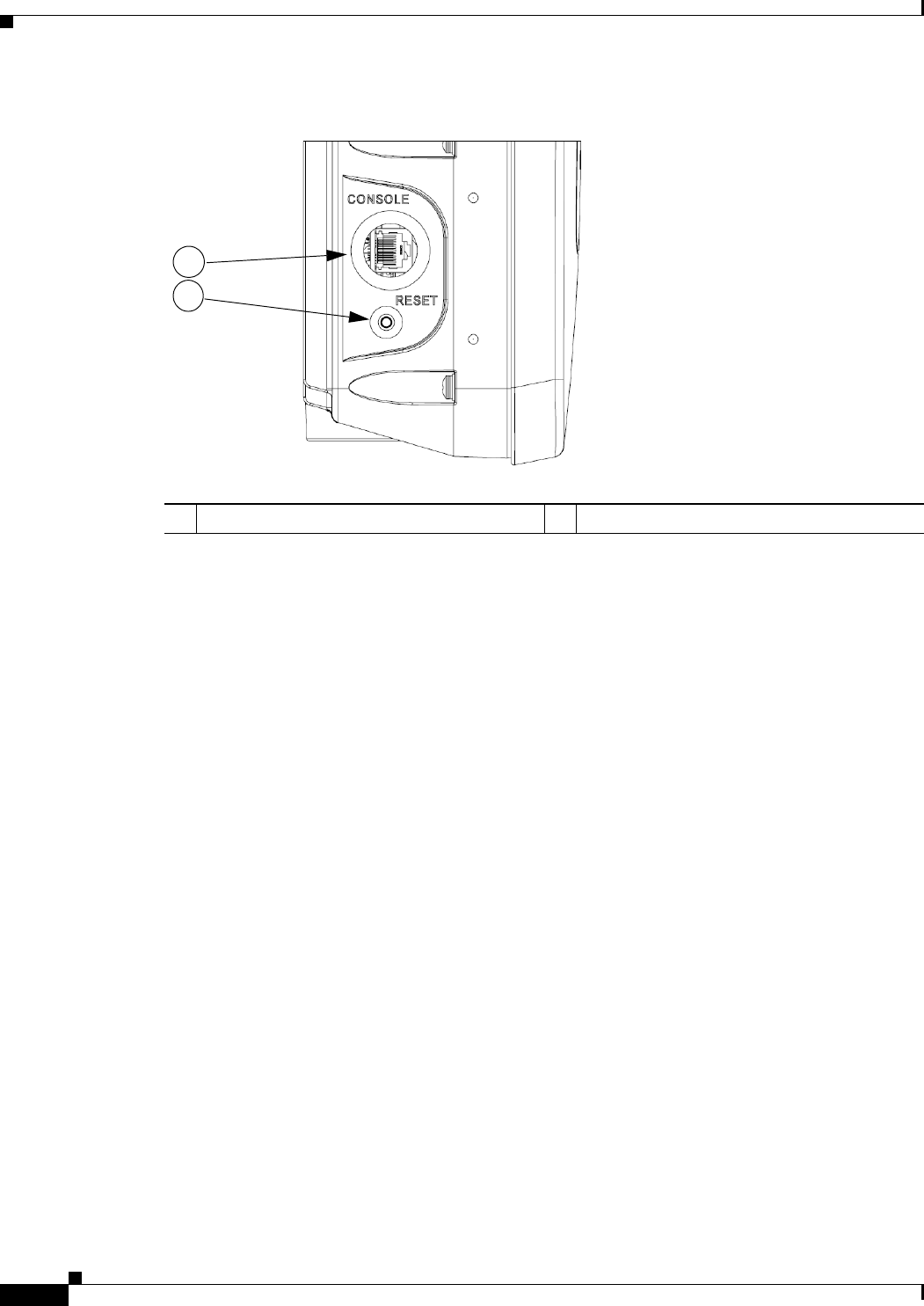
3-8
Cisco Aironet 1560 Series Outdoor Access Point Hardware Installation Guide
Chapter 3 Troubleshooting
Accessing the Console Port and the Reset Button
Figure 3-2 Reset Button Location
1Console Port 2Reset Button
1
2

3-9
Cisco Aironet 1560 Series Outdoor Access Point Hardware Installation Guide
Chapter 3 Troubleshooting
Accessing the Console Port and the Reset Button
Resetting the Access Point
Using the Reset button you can either return the AP back to its default factory-shipped configuration or
download the latest software image from the default TFTP servers.
To use the Reset button:
Step 1 Using a wrench, remove the hex-shaped plug from the Console-Reset port. Do not loose the seal around
the plug.
Step 2 To press and hold the Reset button, use a straightened paperclip or a small screwdriver or a pen.
•To reset the AP back to its default factory-shipped configuration, during power cycle, press and hold
the Reset button (for about 2 to 3 seconds) until the LED blinks amber.
•To download the software image (ap1g3-k9w7-tar.default) from the default TFTP servers (servers
with IP address in the range of 10.0.0.2 to 10.0.0.30), during power cycle, press and hold the Reset
button (for about 20 to 30 seconds) until the LED turns red.
Step 3 Inspect the hex-shaped plug attached to the lanyard for any damage to the sealing face and the gasket. If
the gasket has any signs of damage, it should be replaced to avoid water leakage into the unit.
Step 4 Replace the hex-shaped plug back and tighten it to 15 lbf-in.

3-10
Cisco Aironet 1560 Series Outdoor Access Point Hardware Installation Guide
Chapter 3 Troubleshooting
Accessing the Console Port and the Reset Button

A-1
Cisco Aironet 1560 Series Outdoor Access Point Hardware Installation Guide
APPENDIX
A
Translated Safety Warnings
For translated safety warnings, refer to the safety warning document that shipped with your access point or
that is available on Cisco.com.
To browse to the document on Cisco.com, follow these steps:
Step 1 Click this link and go to the Cisco Wireless documentation home page:
http://www.cisco.com/en/US/products/hw/wireless/index.html
Step 2 Click Support and the Support and Documentation page displays.
Step 3 Click Wireless in the Find Product Support column.
Step 4 Click 1530.
Step 5 Click Install and Upgrade.
Step 6 Click Install and Upgrade Guides.
Step 7 Click Translated Safety Warnings for Cisco Aironet 1560 Series Outdoor Mesh Access Points.

A-2
Cisco Aironet 1560 Series Outdoor Access Point Hardware Installation Guide
Appendix A Translated Safety Warnings

B-1
Cisco Aironet 1560 Series Outdoor Access Point Hardware Installation Guide
APPENDIX
B
Declarations of Conformity and
Regulatory Information
This appendix provides declarations of conformity and regulatory information for the Cisco Aironet
1562 Outdoor Access Point.
This appendix contains the following sections:
•Manufacturers Federal Communication Commission Declaration of Conformity Statement,
page B-2
•Industry Canada, page B-3
•European Community, Switzerland, Norway, Iceland, and Liechtenstein, page B-6
•Declaration of Conformity for RF Exposure, page B-9
•Guidelines for Operating Cisco Aironet Access Points in Japan, page B-10
•VCCI Statement for Japan, page B-11
•Administrative Rules for Cisco Aironet Access Points in Taiwan, page B-11
•EU Declaration of Conformity, page B-13
B-2
Cisco Aironet 1560 Series Outdoor Access Point Hardware Installation Guide
Appendix B Declarations of Conformity and Regulatory Information
Manufacturers Federal Communication Commission Declaration of Conformity Statement
Manufacturers Federal Communication Commission
Declaration of Conformity Statement
Models: FCC Certification number:
Manufacturer:
Cisco Systems, Inc.
170 West Tasman Drive
San Jose, CA 95134-1706
USA
This device complies with Part 15 rules. Operation is subject to the following two conditions:
1. This device may not cause harmful interference, and
2. This device must accept any interference received, including interference that may cause undesired
operation.
This equipment has been tested and found to comply with the limits of a Class A digital device, pursuant
to Part 15 of the FCC Rules. These limits are designed to provide reasonable protection against harmful
interference when the equipment is operated in a residential environment. This equipment generates,
uses, and radiates radio frequency energy, and if not installed and used in accordance with the
instructions, may cause harmful interference. However, there is no guarantee that interference will not
occur. If this equipment does cause interference to radio or television reception, which can be determined
by turning the equipment off and on, the user is encouraged to correct the interference by one of the
following measures:
•Reorient or relocate the receiving antenna.
•Increase separation between the equipment and receiver.
•Connect the equipment to an outlet on a circuit different from which the receiver is connected.
•Consult the dealer or an experienced radio/TV technician.
Caution The Part 15 radio device operates on a non-interference basis with other devices operating at this
frequency when using Cisco-supplied antennas. Any changes or modification to the product not
expressly approved by Cisco could void the user’s authority to operate this device.
Tested To Comply
With FCC Standards
FOR HOME OR OFFICE USE
AIR-AP1562I-B-K9 LDK102104
AIR-AP1562E-B-K9 LKD102103
AIR-AP1562D-B-K9 LDK102104

B-3
Cisco Aironet 1560 Series Outdoor Access Point Hardware Installation Guide
Appendix B Declarations of Conformity and Regulatory Information
Industry Canada
Caution To meet regulatory restrictions, the access point must be professionally installed.
Requirements of operator to register the RLAN device operating Outdoors in the
5150 -5250 MHz band and addressing possible interference issues in this band
Section 15.407(j) of the rules established filing requirements for U-NII operators that deploy a
collection of more than 1000 outdoor access points with the 5.15-5.25 GHz band, parties must submit a
letter to the FCC lab acknowledging that, should harmful interference to licensed services in this band
occur, they will be required to take corrective action. Corrective actions may include reducing power,
turning off devices, changing frequency bands, and/or further reducing power radiated in the vertical
direction.
This material shall be submitted to:
Federal Communications Commission
Laboratory Division, Office of Engineering and Technology
7435 Oakland Mills Road, Columbia, MD, 21046
Attn: U-NII Coordination
or via website at https://www.fcc.gov/labhelp
use subject line U-NII Filing
Industry Canada
Models: IC Certification Number:
Canadian Compliance Statement
This device complies with Industry Canada licence-exempt RSS standard(s). Operation is subject to the
following two conditions: (1) this device may not cause interference, and (2) this device must accept any
interference, including interference that may cause undesired operation of the device.
Le présent appareil est conforme aux CNR d'Industrie Canada applicables aux appareils radio exempts
de licence. L'exploitation est autorisée aux deux conditions suivantes : (1) l'appareil ne doit pas produire
de brouillage, et (2) l'utilisateur de l'appareil doit accepter tout brouillage radioélectrique subi, même si
le brouillage est susceptible d'en compromettre le fonctionnement.
AIR-AP1562I-A-K9 2461B-102104
AIR-AP1562E-A-K9 2461B-102103
AIR-AP1562D-A-K9 2461B-102104

B-4
Cisco Aironet 1560 Series Outdoor Access Point Hardware Installation Guide
Appendix B Declarations of Conformity and Regulatory Information
Industry Canada
Under Industry Canada regulations, this radio transmitter may only operate using an antenna of a type
and maximum (or lesser) gain approved for the transmitter by Industry Canada. To reduce potential radio
interference to other users, the antenna type and its gain should be so chosen that the equivalent
isotropically radiated power (e.i.r.p.) is not more than that necessary for successful communication.
Conformément à la réglementation d'Industrie Canada, le présent émetteur radio peut fonctionner avec
une antenne d'un type et d'un gain maximal (ou inférieur) approuvé pour l'émetteur par Industrie Canada.
Dans le but de réduire les risques de brouillage radioélectrique à l'intention des autres utilisateurs, il faut
choisir le type d'antenne et son gain de sorte que la puissance isotrope rayonnée équivalente (p.i.r.e.) ne
dépasse pas l'intensité nécessaire à l'établissement d'une communication satisfaisante.
This radio transmitter has been approved by Industry Canada to operate with the antenna types listed
below with the maximum permissible gain and required antenna impedance for each antenna type
indicated. Antenna types not included in this list, having a gain greater than the maximum gain indicated
for that type, are strictly prohibited for use with this device.
Le présent émetteur radio a été approuvé par Industrie Canada pour fonctionner avec les types d'antenne
énumérés ci-dessous et ayant un gain admissible maximal et l'impédance requise pour chaque type
d'antenne. Les types d'antenne non inclus dans cette liste, ou dont le gain est supérieur au gain maximal
indiqué, sont strictement interdits pour l'exploitation de l'émetteur.
Operation in the band 5150-5250 MHz is only for indoor use to reduce the potential for harmful
interference to co-channel mobile satellite systems.
La bande 5 150-5 250 MHz est réservés uniquement pour une utilisation à l'intérieur afin de réduire les
risques de brouillage préjudiciable aux systèmes de satellites mobiles utilisant les mêmes canaux.
Users are advised that high-power radars are allocated as primary users (i.e. priority users) of the bands
5250-5350 MHz and 5650-5850 MHz and that these radars could cause interference and/or damage to
LE-LAN devices.
Les utilisateurs êtes avisés que les utilisateurs de radars de haute puissance sont désignés utilisateurs
principaux (c.-à-d., qu'ils ont la priorité) pour les bandes 5 250-5 350 MHz et 5 650-5 850 MHz et que
ces radars pourraient causer du brouillage et/ou des dommages aux dispositifs LAN-EL
Antenna Type Antenna Gain Antenna Impedance
Dual-band Omni 4/7 dBi 50 ohms
Dual-band Omni 7/4 dBi 50 ohms
Dual-Band Directional 9/10 dBi 50 ohms
Single-Band Directional Patch 13/14 dBi 50 ohms

B-5
Cisco Aironet 1560 Series Outdoor Access Point Hardware Installation Guide
Appendix B Declarations of Conformity and Regulatory Information
Declaration of Conformity for RF Exposure
Declaration of Conformity for RF Exposure
This access point product has been found to be compliant to the requirements set forth in CFR 47
Section 1.1307 addressing RF Exposure from radio frequency devices as defined in Evaluating
Compliance with FCC Guidelines for Human Exposure to Radio Frequency Electromagnetic Fields.
AP1562E:To maintain compliance, the minimum separation distance for antennas that have 8 dBi to
14 dBi gain, is 23.6 inches (60 cm) from general bystanders. The minimum separation distance from
antennas that have less than 8 dBi gain to general bystanders is 9.8 inches (25 cm).
AP1562I & AP1562D: To maintain compliance , the minumum seperate distance is 9.8 inches (25cm)
This access point is also compliant to EN 50835 for RF exposure.

B-6
Cisco Aironet 1560 Series Outdoor Access Point Hardware Installation Guide
Appendix B Declarations of Conformity and Regulatory Information
European Community, Switzerland, Norway, Iceland, and Liechtenstein
European Community, Switzerland, Norway, Iceland, and
Liechtenstein
Access Point Models:
AIR-AP1562I-E-K9
AIR-AP1562E-E-K9
AIR-AP1562D-E-K9
Declaration of Conformity with regard to the R&TTE Directive
1999/5/EC & Medical Directive 93/42/EEC
This declaration is only valid for configurations (combinations of software, firmware, and hardware)
provided and supported by Cisco Systems. The use of software or firmware not provided and supported
by Cisco Systems may result in the equipment no longer being compliant with the regulatory
requirements.
B-7
Cisco Aironet 1560 Series Outdoor Access Point Hardware Installation Guide
Appendix B Declarations of Conformity and Regulatory Information
Declaration of Conformity with regard to the R&TTE Directive 1999/5/EC & Medical Directive 93/42/EEC
B-8
Cisco Aironet 1560 Series Outdoor Access Point Hardware Installation Guide
Appendix B Declarations of Conformity and Regulatory Information
Declaration of Conformity with regard to the R&TTE Directive 1999/5/EC & Medical Directive 93/42/EEC
The following standards were applied:
EMC—EN 301.489-1 v1.8.1; EN 301.489-17 v2.1.1
Health & Safety—EN60950-1: 2005; EN 50385: 2002
Radio—EN 300 328 v 1.7.1; EN 301.893 v 1.5.1
The conformity assessment procedure referred to in Article 10.4 and Annex III of Directive 1999/5/EC
has been followed.
This device also conforms to the EMC requirements of the Medical Devices Directive 93/42/EEC.
Note This equipment is intended to be used in all EU and EFTA countries. Outdoor use may be restricted to
certain frequencies and/or may require a license for operation. For more details, contact Cisco Corporate
Compliance.
The product carries the CE Mark:

B-9
Cisco Aironet 1560 Series Outdoor Access Point Hardware Installation Guide
Appendix B Declarations of Conformity and Regulatory Information
Declaration of Conformity for RF Exposure
Declaration of Conformity for RF Exposure
The following is the declaration of conformity for RF exposure for the United States, Canada, European
Union and Australia.
United States
This system has been evaluated for RF exposure for Humans in reference to ANSI C 95.1 (American
National Standards Institute) limits. The evaluation was based on ANSI C 95.1 and FCC OET Bulletin
65C rev 01.01.
AP1562E:To maintain compliance, the minimum separation distance for antennas that have 8 dBi to
14 dBi gain, is 23.6 inches (60 cm) from general bystanders. The minimum separation distance from
antennas that have less than 8 dBi gain to general bystanders is 9.8 inches (25 cm).
AP1562I & AP1562D: To maintain compliance , the minumum seperate distance is 9.8 inches (25cm)
Canada
This system has been evaluated for RF exposure for Humans in reference to ANSI C 95.1 (American
National Standards Institute) limits. The evaluation was based on RSS-102 Rev 5.
AP1562E:To maintain compliance, the minimum separation distance for antennas that have 8 dBi to 14
dBi gain, is 23.6 inches (60 cm) from general bystanders. The minimum separation distance from
antennas that have less than 8 dBi gain to general bystanders is 11.8 inches (30 cm).
AP1562I & AP1562D: To maintain compliance, the minumum seperate distance is 11.8 inches (30cm)
European Union
This system has been evaluated for RF exposure for Humans in reference to the ICNIRP (International
Commission on Non-Ionizing Radiation Protection) limits. The evaluation was based on the EN 50385
Product Standard to Demonstrate Compliance of Radio Base stations and Fixed Terminals for Wireless
Telecommunications Systems with basic restrictions or reference levels related to Human Exposure to
Radio Frequency Electromagnetic Fields from 300 MHz to 40 GHz. To maintain compliance, the
minimum separation distance for antennas that have 8 dBi to 14 dBi gain, is 23.6 inches (60 cm)
from general bystanders. The minimum separation distance from antennas that have less than 8 dBi
gain to general bystanders is 9.8 inches (25 cm).
Australia
This system has been evaluated for RF exposure for Humans as referenced in the Australian Radiation
Protection standard and has been evaluated to the ICNIRP (International Commission on Non-Ionizing
Radiation Protection) limits. To maintain compliance, the minimum separation distance for antennas
that have 8 dBi to 14 dBi gain, is 23.6 inches (60 cm) from general bystanders. The minimum
separation distance from antennas that have less than 8 dBi gain to general bystanders is 9.8 inches
(25 cm).
B-10
Cisco Aironet 1560 Series Outdoor Access Point Hardware Installation Guide
Appendix B Declarations of Conformity and Regulatory Information
Guidelines for Operating Cisco Aironet Access Points in Japan
Guidelines for Operating Cisco Aironet Access Points in Japan
This section provides guidelines for avoiding interference when operating Cisco Aironet access points
in Japan. These guidelines are provided in both Japanese and English.
Access Point Model:
AIR-AP1562E-Q-K9
AIR-AP1562I-Q-K9
AIR-AP1562D-Q-K9
Japanese Translation
English Translation
This equipment operates in the same frequency bandwidth as industrial, scientific, and medical devices
such as microwave ovens and mobile object identification (RF-ID) systems (licensed premises radio
stations and unlicensed specified low-power radio stations) used in factory production lines.
1. Before using this equipment, make sure that no premises radio stations or specified low-power radio
stations of RF-ID are used in the vicinity.
2. If this equipment causes RF interference to a premises radio station of RF-ID, promptly change the
frequency or stop using the device; contact the number below and ask for recommendations on
avoiding radio interference, such as setting partitions.
3. If this equipment causes RF interference to a specified low-power radio station of RF-ID, contact
the number below.
Contact Number: 03-6434-6500
03-6434-6500
43768
B-11
Cisco Aironet 1560 Series Outdoor Access Point Hardware Installation Guide
Appendix B Declarations of Conformity and Regulatory Information
Administrative Rules for Cisco Aironet Access Points in Taiwan
VCCI Statement for Japan
Administrative Rules for Cisco Aironet Access Points in Taiwan
This section provides administrative rules for operating Cisco Aironet Access Points in Taiwan. The
rules are provided in both Chinese and English.
Chinese Translation
Warning
This is a Class A product based on the standard of the Voluntary Control Council for Interference by
Information Technology Equipment (VCCI). If this equipment is used in a domestic environment, radio
disturbance may arise. When such trouble occurs, the user may be required to take corrective
actions.
B-12
Cisco Aironet 1560 Series Outdoor Access Point Hardware Installation Guide
Appendix B Declarations of Conformity and Regulatory Information
Administrative Rules for Cisco Aironet Access Points in Taiwan
English Translation
Administrative Rules for Low-power Radio-Frequency Devices
Article 12
For those low-power radio-frequency devices that have already received a type-approval, companies,
business units or users should not change its frequencies, increase its power or change its original
features and functions.
Article 14
The operation of the low-power radio-frequency devices is subject to the conditions that no harmful
interference is caused to aviation safety and authorized radio station; and if interference is caused, the
user must stop operating the device immediately and can't re-operate it until the harmful interference is
clear.
The authorized radio station means a radio-communication service operating in accordance with the
Communication Act.
The operation of the low-power radio-frequency devices is subject to the interference caused by the
operation of an authorized radio station, by another intentional or unintentional radiator, by industrial,
scientific and medical (ISM) equipment, or by an incidental radiator.
Chinese Translation
English Translation
Low-power Radio-frequency Devices Technical Specifications
4.7
Unlicensed National Information Infrastructure
4.7.6
The U-NII devices shall accept any interference from legal communications and shall not interfere the
legal communications. If interference is caused, the user must stop operating the device immediately and
can't re-operate it until the harmful interference is clear.
B-13
Cisco Aironet 1560 Series Outdoor Access Point Hardware Installation Guide
Appendix B Declarations of Conformity and Regulatory Information
Operation of Cisco Aironet Access Points in Brazil
4.7.7
Manufacturers of U-NII devices are responsible for ensuring frequency stability such that an emission
is maintained within the band of operation under all conditions of normal operation as specified in the
user manual.
Statement 371—Power Cable and AC Adapter
English Translation
When installing the product, please use the provided or designated connection cables/power cables/AC
adapters. Using any other cables/adapters could cause a malfunction or a fire. Electrical Appliance and
Material Safety Law prohibits the use of UL-certified cables (that have the “UL” shown on the code) for
any other electrical devices than products designated by CISCO. The use of cables that are certified by
Electrical Appliance and Material Safety Law (that have “PSE” shown on the code) is not limited to
CISCO-designated products.
EU Declaration of Conformity
All the Declaration of Conformity statements related to this product can be found at the following
location:
http://www.ciscofax.com
Operation of Cisco Aironet Access Points in Brazil
This section contains special information for operation of Cisco Aironet access points in Brazil.
Access Point Models
AIR-AP1562E-Z-K9
AIR-AP1562I-Z-K9
AIR-AP1562D-Z-K9

B-14
Cisco Aironet 1560 Series Outdoor Access Point Hardware Installation Guide
Appendix B Declarations of Conformity and Regulatory Information
Operation of Cisco Aironet Access Points in Brazil
Regulatory Information
Figure B-1 contains Brazil regulatory information for the access point models identified in the previous
section.
Figure B-1 Brazil Regulatory Information
Portuguese Translation
Este equipamento opera em caráter secundário, isto é, não tem direito a proteção contra interferência
prejudicial, mesmo de estações do mesmo tipo, e não pode causar interferência a sistemas operando em
caráter primário.
English Translation
This equipment operates on a secondary basis and consequently must accept harmful interference,
including interference from stations of the same kind. This equipment may not cause harmful
interference to systems operating on a primary basis.

C-1
Cisco Aironet 1560 Series Outdoor Access Point Hardware Installation Guide
APPENDIX
C
Channels and Power Levels
For channel and maximum power level settings, refer to the Channels and Maximum Power Settings for
Cisco Aironet Lightweight Access Points and Bridges document available on the Cisco Wireless
documentation page of Cisco.com.
To browse to the document, follow these steps:
Step 1 Click this link and go to the Cisco Wireless documentation home page:
http://www.cisco.com/en/US/products/hw/wireless/index.html
Step 2 Click Support. The Support and Documentation page displays.
Step 3 Click Wireless
Step 4 Click 1560.
Step 5 Click Install and Upgrade.
Step 6 Click Install and Upgrade Guides.
Step 7 Click Channels and Maximum Power Settings for Cisco 1560 Series Outdoor Access Points document.

C-2
Cisco Aironet 1560 Series Outdoor Access Point Hardware Installation Guide
Appendix C Channels and Power Levels

D-1
Cisco Aironet 1560 Series Outdoor Access Point Hardware Installation Guide
APPENDIX
D
Access Point Data Sheet
The detailed technical specifications for the Cisco Aironet 1560 Series Outdoor Access Points are
available at the following URL:
http://www.cisco.com/c/en/us/products/collateral/wireless/aironet-1560-series/datasheet-c78-737416.h
tml
You can also download a copy of the Cisco Aironet 1560 Series Outdoor Access Point Data Sheet from
the above URL for offline use.

D-2
Cisco Aironet 1560 Series Outdoor Access Point Hardware Installation Guide
Appendix D Access Point Data Sheet
E-1
Cisco Aironet 1560 Series Outdoor Access Point Hardware Installation Guide
APPENDIX
E
Access Point Pinouts
This appendix describes the pin signals of the access point Ethernet connectors, and the power injector
input and output connectors.
Table E-1 describes the pin signals of the access point LAN connector
Table E-2 describes the pin signals for the power injector input connector (To Switch).
Table E-1 Access Point LAN Connector Pinouts
Pin Number Signal Name
1 Ethernet signal pair (10/100/1000BASE-T)
2
3 Ethernet signal pair (10/100/1000BASE-T)
6
4 Ethernet signal pair (10/100/1000BASE-T)
5
7 Ethernet signal pair (10/100/1000BASE-T)
8
Shield Chassis ground
Table E-2 Power Injector Input Connector (To Switch) Pinouts
Pin Number Signal Name
1 Ethernet signal pair (10/100/1000BASE-T)
2
3 Ethernet signal pair 10/100/1000BASE-T)
6
4 Ethernet signal pair (1000BASE-T)
5
7 Ethernet signal pair (1000BASE-T)
8
Shield Chassis ground

E-2
Cisco Aironet 1560 Series Outdoor Access Point Hardware Installation Guide
Appendix E Access Point Pinouts

F-1
Cisco Aironet 1560 Series Outdoor Access Point Hardware Installation Guide
APPENDIX
F
Configuring DHCP Option 43
For information on how to configure how to use DHCP Option 43 and to see sample configurations for
DHCP Option 43 for lightweight Cisco Aironet access points (LAPs), go to the following URL:
http://www.cisco.com/c/en/us/support/docs/wireless-mobility/wireless-lan-wlan/97066-dhcp-option-43
-00.html

F-2
Cisco Aironet 1560 Series Outdoor Access Point Hardware Installation Guide
Appendix F Configuring DHCP Option 43