Cisco Systems 62009015 802.11a/b/g/n MINI-PCI Module User Manual
Cisco Systems 802.11a/b/g/n MINI-PCI Module Users Manual
UserManual.wiki
>
Cisco Systems
>
62009015 User Manual
>
Users Manual
Contents
1.
Users Manual regulatory notice
2.
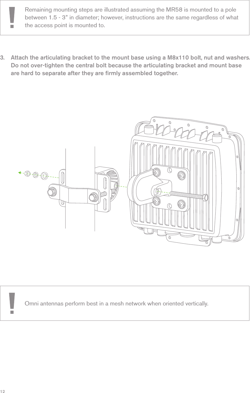
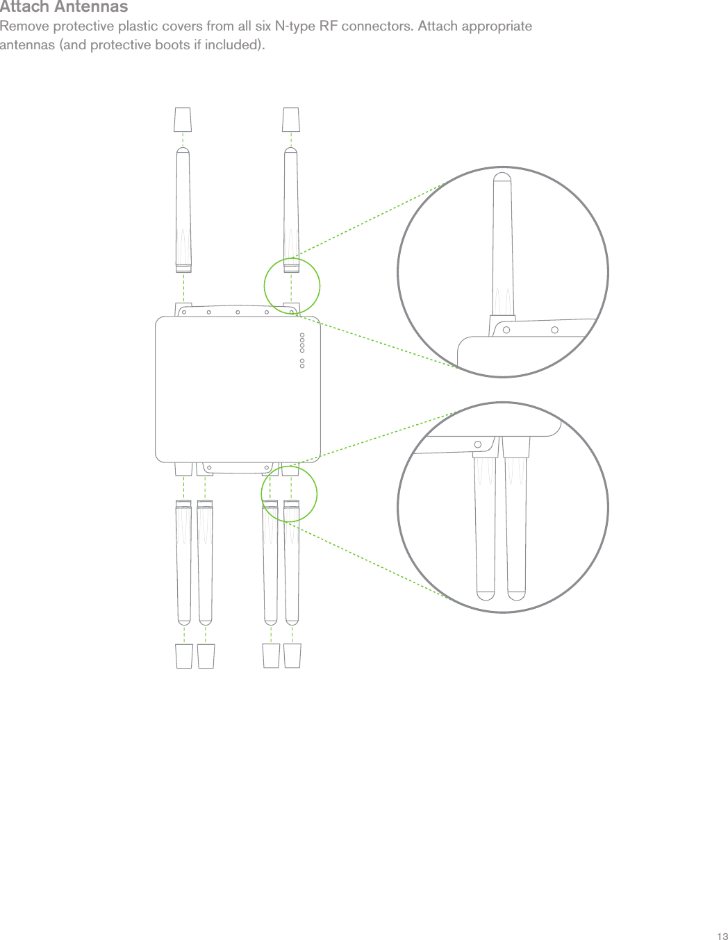
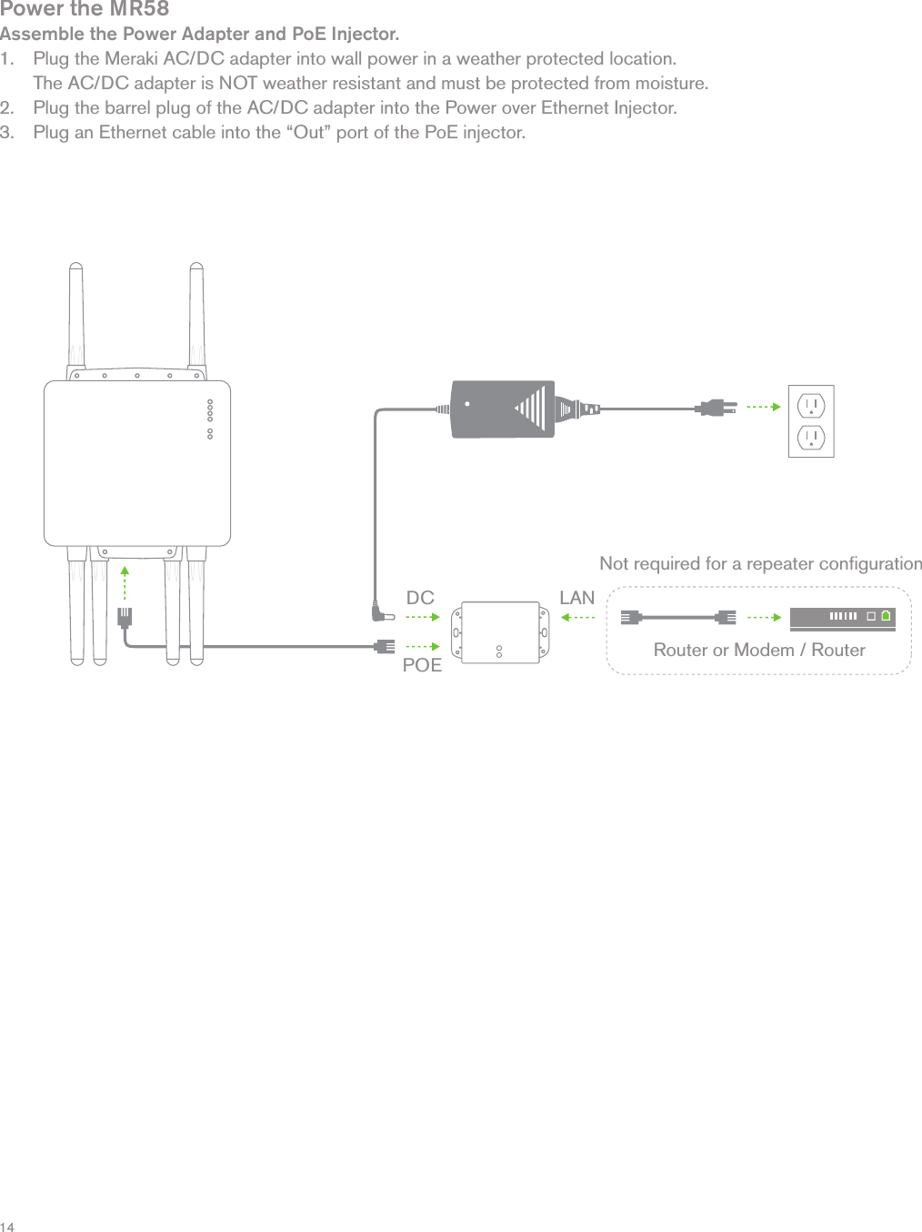
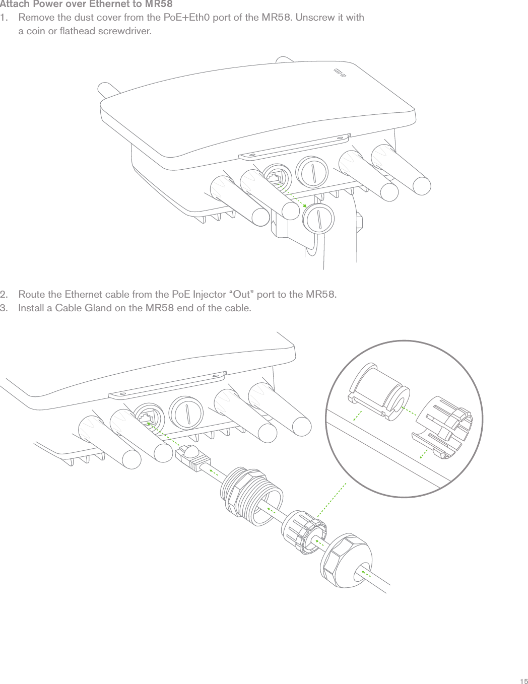
Users Manual
3.
Users Manual regulatory notice
Users Manual
Navigation menu
Upload a User Manual
Namespaces
Wiki Guide
HTML
PDF
Info
Views
User Manual
Discussion / Help
Navigation