Cisco Systems 62009015 802.11a/b/g/n MINI-PCI Module User Manual
Cisco Systems 802.11a/b/g/n MINI-PCI Module Users Manual
Contents
Users Manual
Meraki MR
Hardware Setup Guide
58
1
Contents
· System Overview 2
· Understanding the MR58 4
· Pre-Site Preparation 7
· On-Site Instructions 8
· Troubleshooting 16
2
System Overview
The Meraki MR58 enables you to create large, high-speed wireless networks quickly,
easily and cost-effectively.
Meraki MR58
An MR58 system consists of four basic components: the access point, the mounting
system, the Power over Ethernet system, and the antennas. The following section
describes each component in more detail.
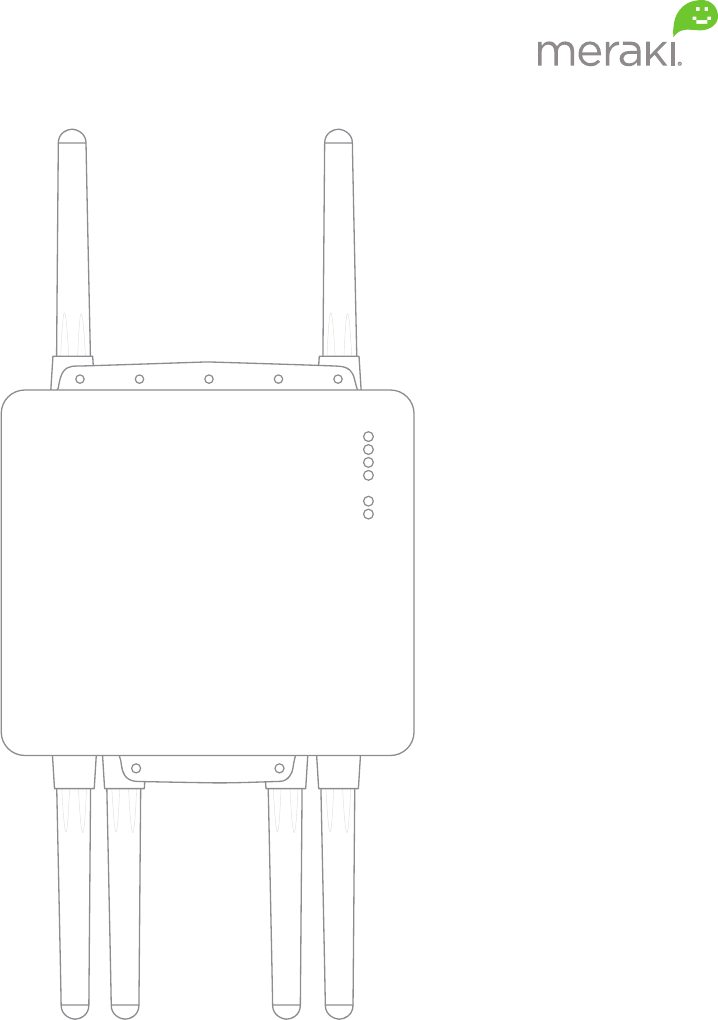
MR58 Access Point
The MR58 Access Point is the core of the system. It contains three 802.11n radios
integrated into a ruggedized, weatherproof enclosure.
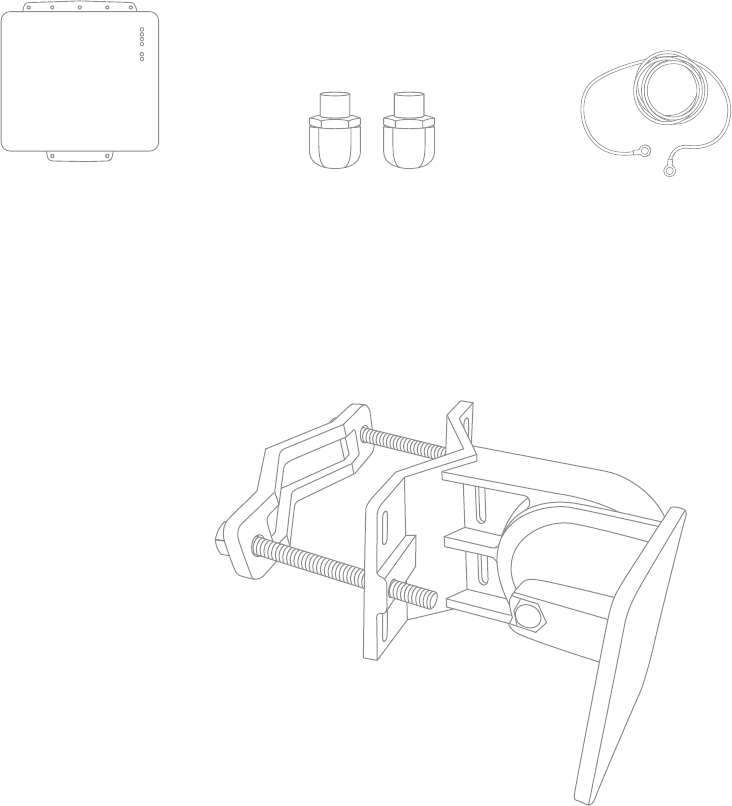
This MR58 package contains the following:
Mounting System
The MR58 mounting system (included) allows you to attach the MR58 to walls, ceilings and poles.
MR58 access point Grounding strap2 Cable glands
3
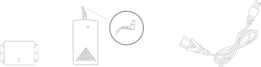
Power System - Power over Ethernet (PoE)
The Meraki MR58 accepts Power over Ethernet (802.3af); the Meraki PoE 802.3af injector
is sold separately. Instructions contained in this setup guide assume your MR58 will be
powered by the Meraki PoE 802.3af injector.
The power system contains the following:
Antennas
The Meraki MR58 has three 802.11n radios. Each radio has two external antenna connectors;
both connectors for a particular radio should be attached to the same type of antenna.
Meraki offers a number of different antennas for use with the MR58. Alternately, you may
purchase 3rd party antennas for use with the MR58. Make sure they have N-type connectors
and support the proper frequency band (2.4 or 5GHz).
PoE injector Country-specific AC power cableAC/DC Power converter with barrel plug
4
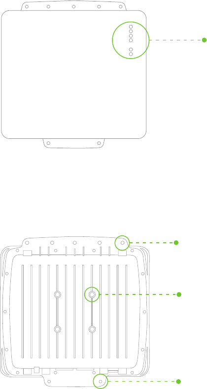
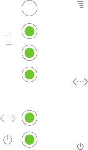
LED indicators
Accessory antenna attachment holes
Accessory antenna attachment holes
Understanding the MR58
Your Meraki MR58 has the following features:
Mount attachment holes
5
Signal Strength
One Light: Fair
Four Lights: Strongest
Moving Lights: Searching for signal
Flashing Lights: Error state. May indicate bad gateway or other routing fault
Ethernet
Off: No active network connection on either ethernet port
On: An active network connection is connected to either Eth0 or Eth1
Flashing: Error state. May indicate bad gateway or other routing fault
Radio Power
Off: MR58 is off
On – ORANGE: MR58 is booting or trying to find a path to the internet
On – GREEN: MR58 is fully operational and connected to the network
Flashing – ORANGE: Firmware is upgrading
Flashing – GREEN: Error state. May indicate bad gateway or other routing fault
Understanding the LED Indicators
Your MR58 is equipped with a series of LED lights on the front of the unit to convey
information about system functionality and performance.
6
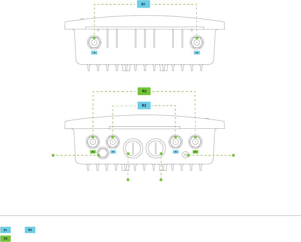
ETH0+PoE ETH1
and are 5GHz radios for mesh or client communication. Each radio has two external N-type connectors.
is a 2.4GHz radio primarily used for client communication. However, it can also communicate with Meraki
2.4Ghz access points. This radio has two external N-type connectors.
Vent
The vent allows pressure and humidity equalization between the interior and the enviroment. This prevents
internal condensation and maintains a water proof seal.
Grounding Post
Provides an attachment point on the Access Point for the grounding strap (included). This post is threaded
to accept a M4 x 0.7mm bolt
Understanding the Ports
TOP
BOTTOM
Primary ethernet
and power port
Secondary
ethernet port
Vent Grounding post

7
Pre-Site Preparation
You should complete the following steps before going on-site to perform the installation.
RecommendedRequired
Straight-slot
screwdriver
Phillips
screwdriver
9/16”(13mm)
wrenches
Adjustable wrench
Rubber mallet
Drill with appropriate bits
for mounting wall anchors
(if mounting to a wall)
Power screwdriver with 5/16”
(8 mm) nut driver, Phillips & flat heads
x 2
Tin snips
(if mounting with hose clamps)
Collect Additional Hardware for Installation
Required
Network cables with RJ45 connectors long enough for your particular
mounting location
Connection to the internet (if you are setting up your MR58 as a gateway
to the internet)
Appropriately sized metal straps (if mounting to a pole larger than 3.0”
in diameter)
Specialized mounting hardware if mounting to surface other than wood,
stucco or stone
Recommended
Laptop with wireless to verify setup
Collect Tools
You will need the following tools to perform your installation:
8
Configure Your Network in Dashboard
We recommend that you add your MR58 to a network in Dashboard before mounting it in the field.
1. Login to http//dashboard.meraki.com. If this is your first time, create a new account.
2. Find the network to which you plan to add your nodes.
3. Add your nodes to your network. You will need your Meraki order number (found on your
invoice) or the serial number of each node, which looks like Q2xx-xxxx-xxxx, and is found
on the bottom of the unit.
4. Finally, go to the map view and place each node on the map by clicking and dragging
it to the location where you plan to mount it. You can always modify the location later.
* If you do choose to add the node to Dashboard after the installation, make sure to
write down the serial number and MAC address of the unit before installing.
On-Site Instructions
Find a Good Mounting Location
A good mounting location is important to getting the best performance out of your MR58
Access Point. Keep the following in mind:
1. The Power over Ethernet System supports a maximum cable length of 100m.
The Power over Ethernet Adapter and Injector are not rated for outdoor use, and
must be installed indoors or in a weatherproof outdoor-rated enclosure.
2. The Meraki MR58 should have line of sight to as many other Meraki devices as
possible. If being installed as a repeater, special care should be taken to optimize
the view in the direction of the closest known gateway.
3. The antennas should be as unobstructed as possible. Make sure that there is
clearance around the MR58 for installation of all of your chosen antennas.
9
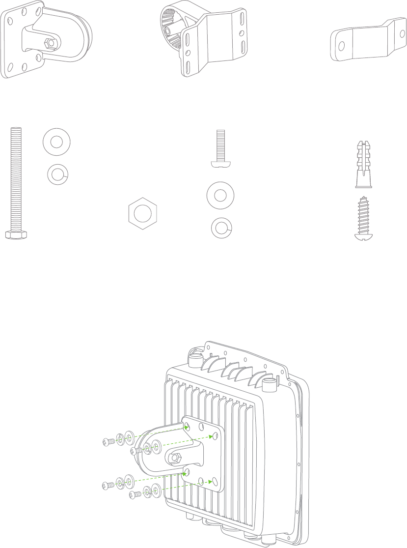
Articulating bracket Mount base Pole mount V-bar
M8 x 110
screws and washers
M8 nut M5 x 12
screws and washers
Wood screws and anchors
x 2
x 2
x 3
x 3
x 3
Mount the MR58
Your mounting system contains the following:
1. Attach the articulating bracket to back of the MR58 using M5 screws and washers.
x 4
x 4
x 4
10
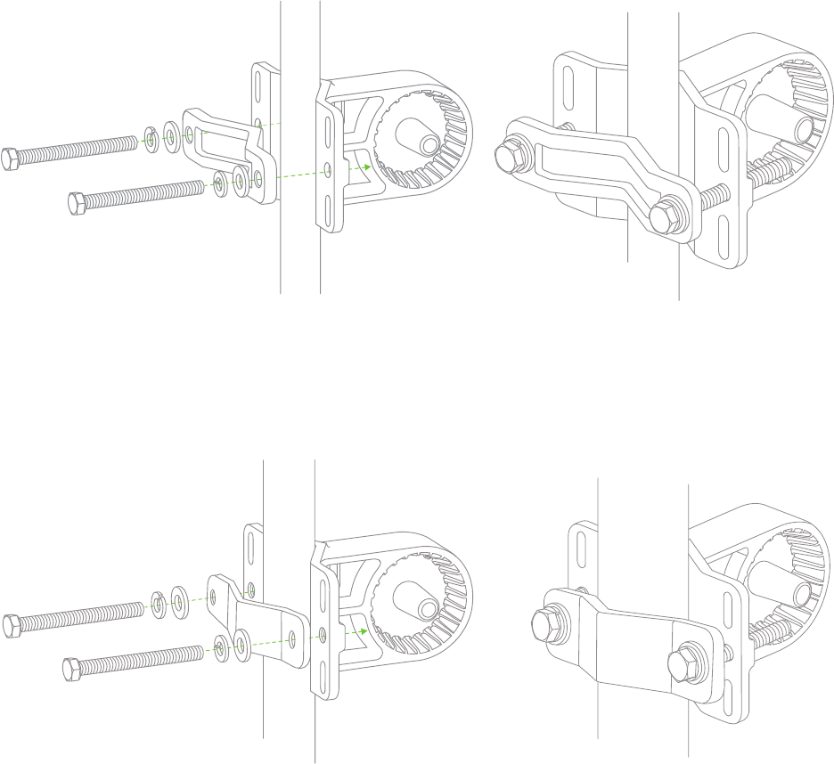
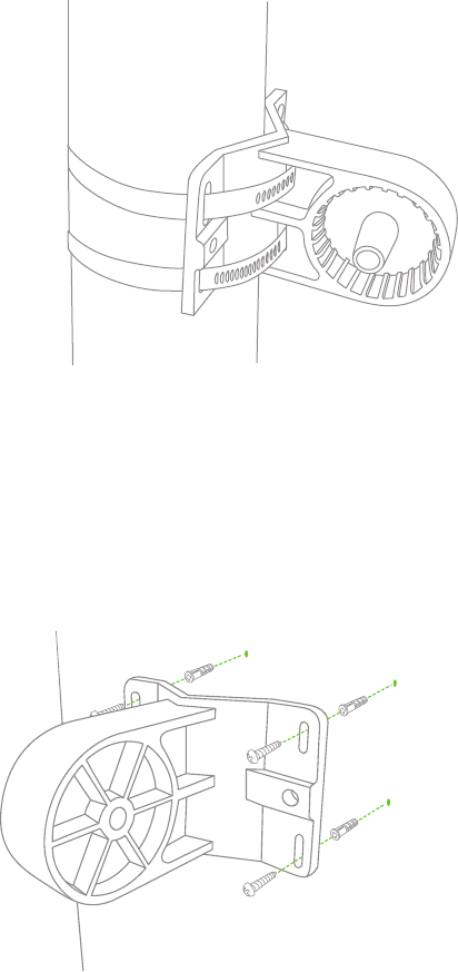
Mounting for poles less than 1.5” (35mm)
Attach mount base and V-bar to pole as shown using M8 bolts and washer.
Mounting for poles less than 3” (80mm) and larger than 1.5” (35mm)
Attach mount base and V-bar to pole as shown using M8 bolts and washers.
2. Attach mount base to mounting structure (pole, wall or ceiling). Before tightening
fasteners, make sure that the MR58 will be pointing in the correct direction after
mounting.
11
Mounting for poles larger that 3” (80mm)
Attach mount base to pole using appropriately-sized metal straps (not included).
Mounting on walls
Using appropriate wall anchors and screws for the surface you are mounting to (if mounting to
wood, stucco or stone, use anchors and screws included with mount), attach the mount base
to your mounting wall.
12
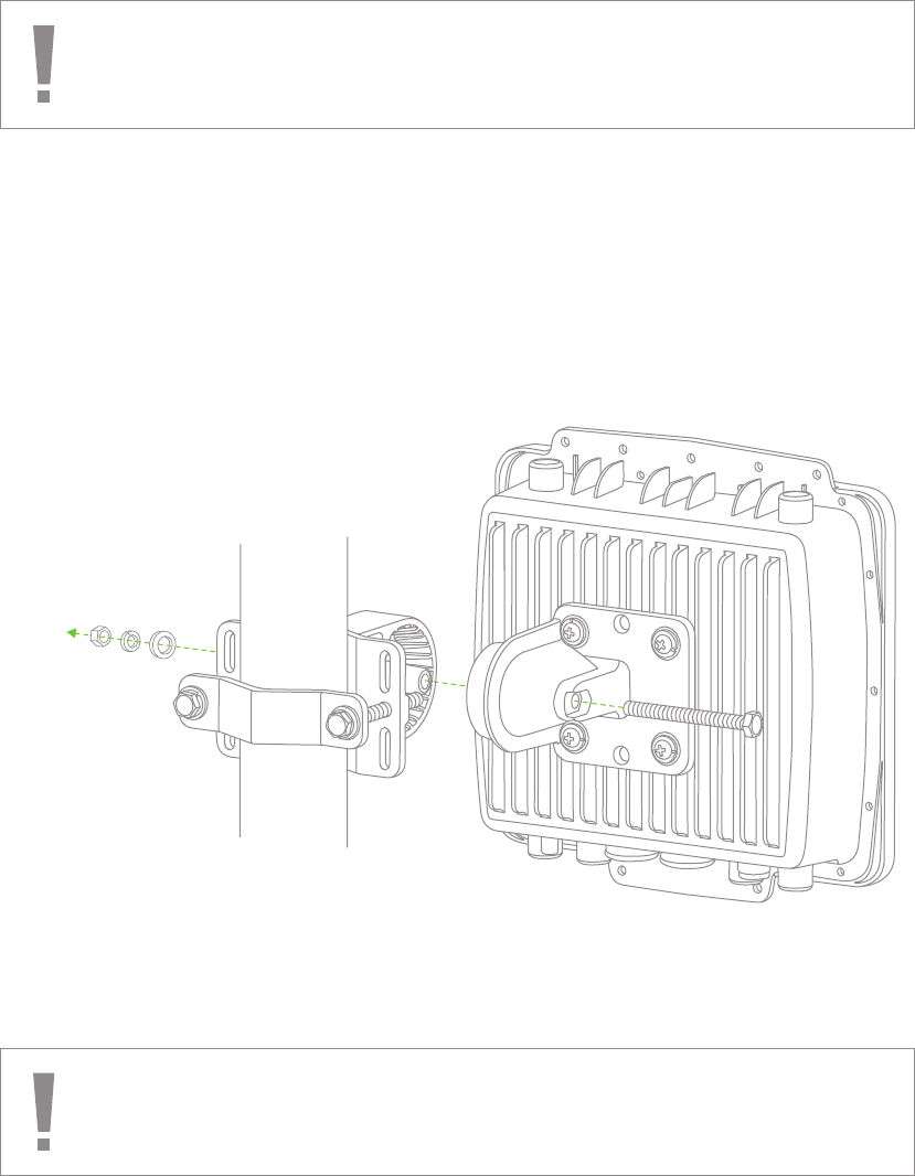
Remaining mounting steps are illustrated assuming the MR58 is mounted to a pole
between 1.5 - 3” in diameter; however, instructions are the same regardless of what
the access point is mounted to.
Omni antennas perform best in a mesh network when oriented vertically.
3. Attach the articulating bracket to the mount base using a M8x110 bolt, nut and washers.
Do not over-tighten the central bolt because the articulating bracket and mount base
are hard to separate after they are firmly assembled together.
13
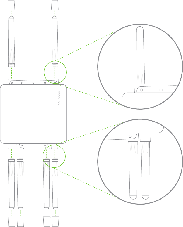
Attach Antennas
Remove protective plastic covers from all six N-type RF connectors. Attach appropriate
antennas (and protective boots if included).
14
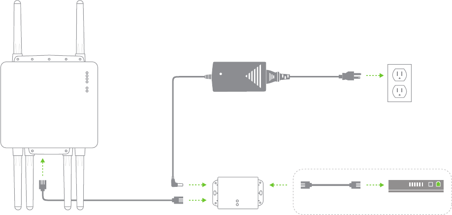
Power the MR58
Assemble the Power Adapter and PoE Injector.
1. Plug the Meraki AC/DC adapter into wall power in a weather protected location.
The AC/DC adapter is NOT weather resistant and must be protected from moisture.
2. Plug the barrel plug of the AC/DC adapter into the Power over Ethernet Injector.
3. Plug an Ethernet cable into the “Out” port of the PoE injector.
Not required for a repeater configuration
Router or Modem / Router
LANDC
POE
15
2. Route the Ethernet cable from the PoE Injector “Out” port to the MR58.
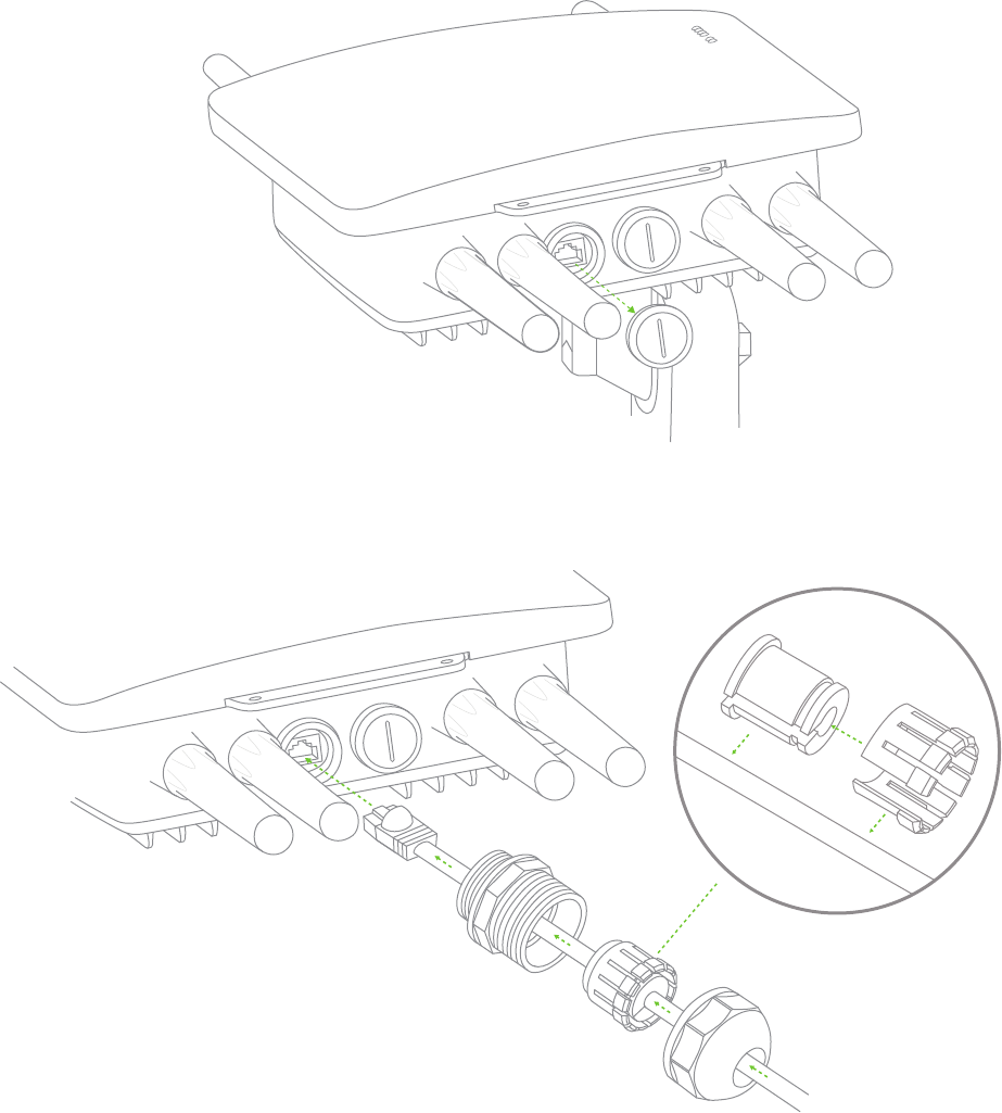
3. Install a Cable Gland on the MR58 end of the cable.
Attach Power over Ethernet to MR58
1. Remove the dust cover from the PoE+Eth0 port of the MR58. Unscrew it with
a coin or flathead screwdriver.
16
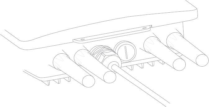
4. Plug the Ethernet cable into the PoE+Eth0 port of the Meraki MR58.
a. Connect the cable to the port on the MR58.
b. Screw the gland body into the threaded hole of the port. Use an adjustable
wrench to make sure the gland body is fully seated in the hole.
c. Insert the split ring gasket into the gland body.
d. Screw the cap tightly onto the gland. You may need a wrench to fully
tighten the cap, but take care not to damage the cable in the process.
Optional: Make the MR58 a gateway
1. Connect an active internet connection to the “In” port of the PoE injector.
Aim Antennas
If you are using directional antennas, aim them appropriately to ensure optimal
performance for your specific network topography.
Test Your Network
Confirm that you have good signal strength throughout your coverage area.
You can use the signal strength meter on a laptop.
Troubleshooting
See the Meraki knowledge base at http://meraki.com/help/kb for additional information
and troubleshooting tips.
17
FCC and Other Disclosures
US – Federal Communication Commission Interference Statement
This device complies with Part 15 of the FCC Rules. Operation is subject to
the following two conditions: (1) This device may not cause harmful interference,
and (2) this device must accept any interference received, including interference
that may cause undesired operation.
This equipment has been tested and found to comply with the limits for a Class B
digital device, pursuant to Part 15 of the FCC rules. These limits are designed to
provide reasonable protection against harmful interference in a residential installation.
This equipment generates, uses, and can radiate radio frequency energy and,
if not installed and used in accordance with the instructions, may cause harmful
interference to radio communications. However, there is no guarantee that
interference will not occur in a particular installation. If this equipment does cause
harmful interference to radio or television reception, which can be determined by
turning the equipment off and on, the user is encouraged to try to correct the
interference by one of the following measures:
· Reorient or relocate the receiving antenna.
· Increase the separation between the equipment and receiver.
· Connect the equipment into an outlet on a circuit different from
that to which the receiver is connected.
· Consult the dealer or an experienced radio/TV technician for help.
Any changes or modifications not expressly approved by Meraki, Inc. could void
the user’s authority to operate this equipment.
EU – EN 55 022 Declaration of Conformance
This equipment is shielded against the generation of radio interference in accordance
with the application of Council Directive 89/336/EEC, Article 4a. Conformity is
declared by the application of EN 55 022 Class B (CISPR 22).
For more information,
visit meraki.com/oursolution/hardware/MR58/meraki_MR58_reg.pdf
© Meraki, Inc. 2009 280-09100-A