Cisco Systems ATBRTH16 802.11a/h radio User Manual mr50wmic
Cisco Systems Inc 802.11a/h radio mr50wmic
UserManual.wiki
>
Cisco Systems
>
ATBRTH16 User Manual
>
WMIC operational manual
Contents
1.
WMIC operational manual
2.
USER MANUAL
WMIC operational manual
Navigation menu
Upload a User Manual
Namespaces
Wiki Guide
HTML
PDF
Info
Views
User Manual
Discussion / Help
Navigation
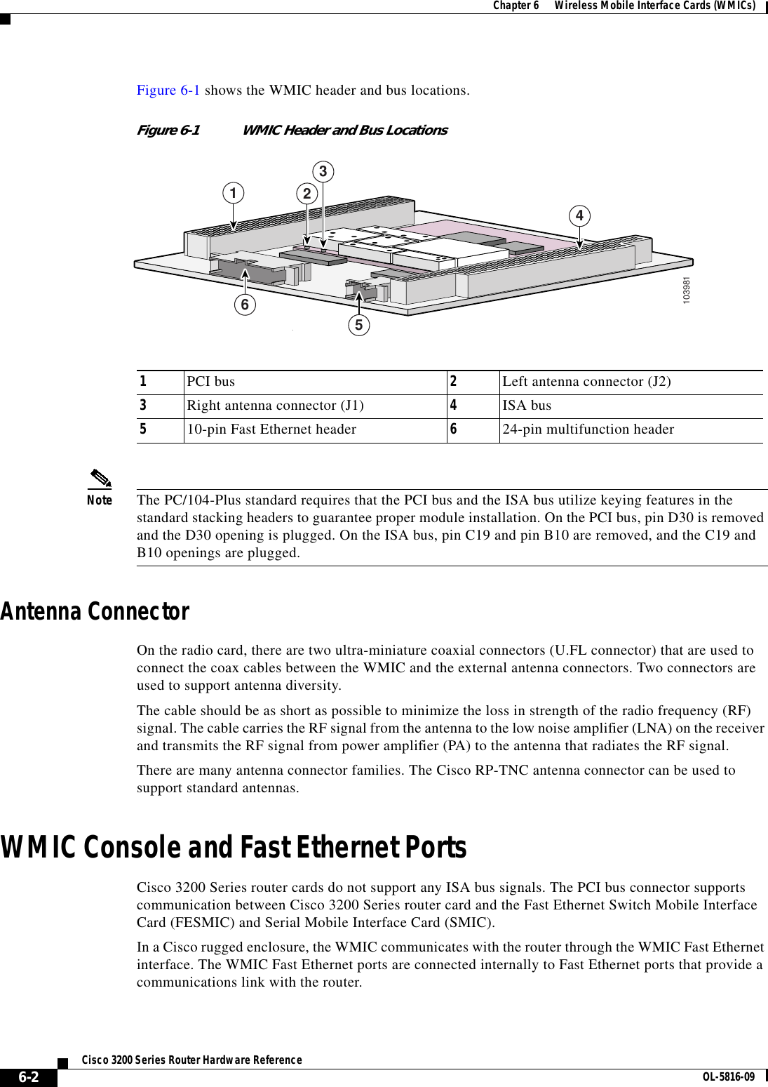
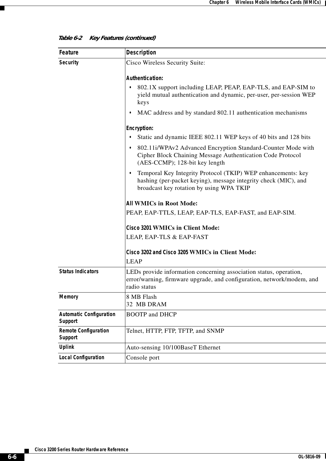
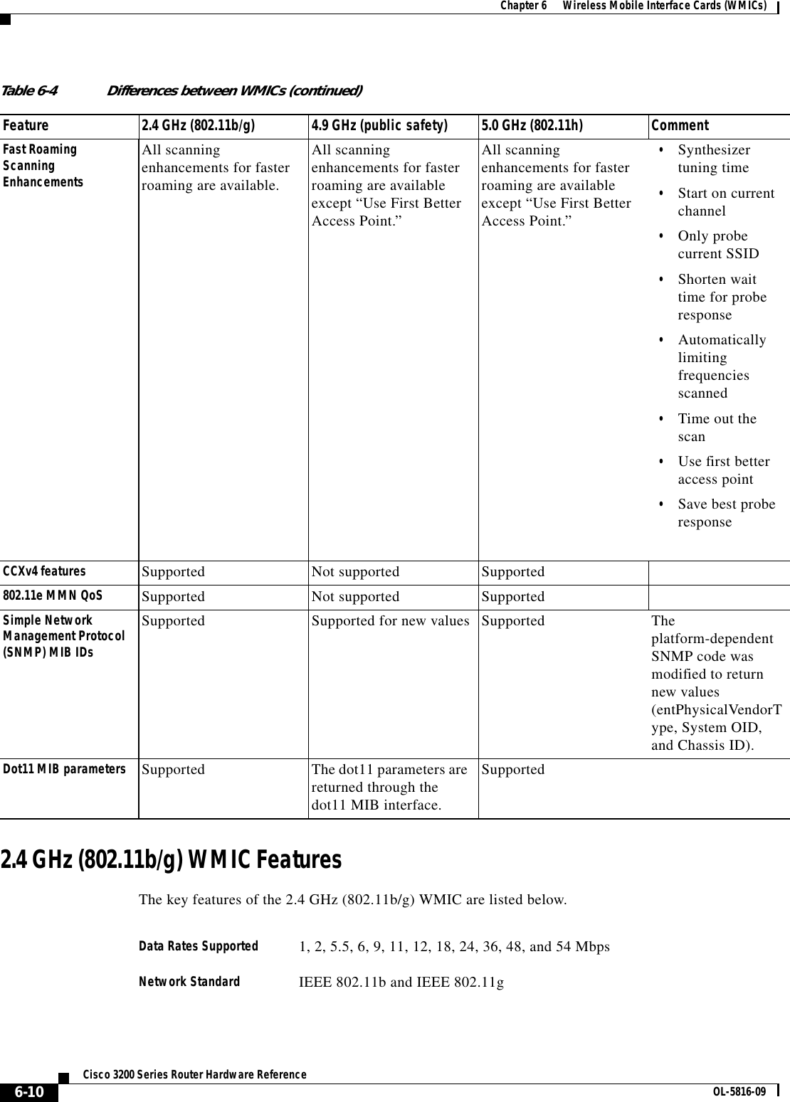
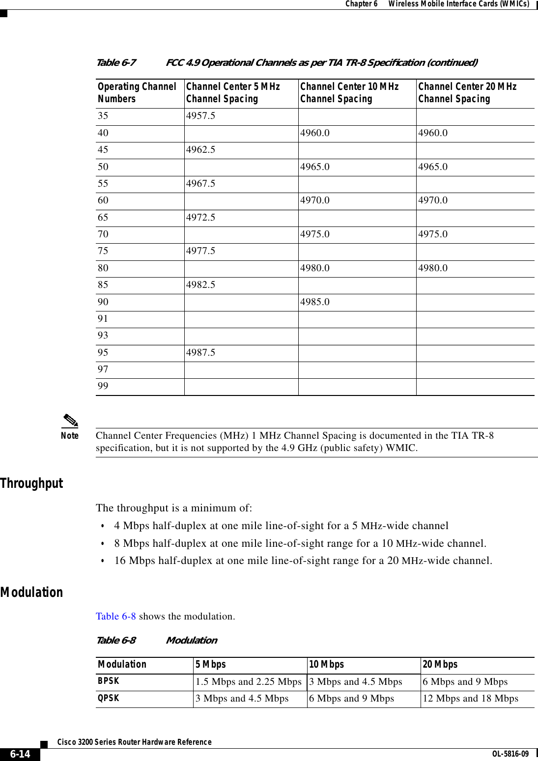
![CHAPTER6-1Cisco 3200 Series Router Hardware ReferenceOL-5816-096Wireless Mobile Interface Cards (WMICs)The Cisco Wireless Mobile Interface Card (WMIC) is a Cisco 3200 Series router interface card in astandard PC/104-Plus form factor.It is one component of the Cisco 3200 Series routers and provides a wireless interface:•2.4 GHz (802.11b/g) – Cisco 3201•4.9 GHz (public safety) – Cisco 3202•5.0 GHz (802.11h) – Cisco 3205 (The C3205WMIC-K9 and C3205WMIC-TP-K9 WMICs areavailable only in the European Telecommunications Standards Institute [ETSI] domain.)Caution The 4.9 GHz (public safety) radio requires an operators license and can only be operated by US PublicSafety operators who meet the requirements specified under FCC Part 90.20.This chapter provides basic information about the WMIC hardware for the purpose of performing simpletroubleshooting, such as reconnecting a loose cable. To solve more difficult problems, please contactyour vendor.WMIC Component SystemsThe ISA buses and PCI buses on the Cisco 3200 Series router cards provide power to the componentson the cards. The WMIC does not receive or transmit communications signals on either bus, but it willpass signals through the bus to a card above or below the WMIC. Both buses comply with thePC/104-Plus standard.The PCI bus signals allow the Cisco cards to communicate. Non-Cisco cards cannot communicate withthe Cisco 3200 Series Router cards over the PCI bus.Caution If you add non-Cisco cards that generates signals on the PCI bus, the router might shut down. Please donot add non-Cisco cards that generate signals on the PCI bus.](https://usermanual.wiki/Cisco-Systems/ATBRTH16.WMIC-operational-manual/User-Guide-885074-Page-1.png)