Cisco Systems ATBRTH16 802.11a/h radio User Manual mr50wmic
Cisco Systems Inc 802.11a/h radio mr50wmic
Contents
- 1. WMIC operational manual
- 2. USER MANUAL
WMIC operational manual

CHAPTER
6-1
Cisco 3200 Series Router Hardware Reference
OL-5816-09
6
Wireless Mobile Interface Cards (WMICs)
The Cisco Wireless Mobile Interface Card (WMIC) is a Cisco 3200 Series router interface card in a
standard PC/104-Plus form factor.
It is one component of the Cisco 3200 Series routers and provides a wireless interface:
•2.4 GHz (802.11b/g) – Cisco 3201
•4.9 GHz (public safety) – Cisco 3202
•5.0 GHz (802.11h) – Cisco 3205 (The C3205WMIC-K9 and C3205WMIC-TP-K9 WMICs are
available only in the European Telecommunications Standards Institute [ETSI] domain.)
Caution The 4.9 GHz (public safety) radio requires an operators license and can only be operated by US Public
Safety operators who meet the requirements specified under FCC Part 90.20.
This chapter provides basic information about the WMIC hardware for the purpose of performing simple
troubleshooting, such as reconnecting a loose cable. To solve more difficult problems, please contact
your vendor.
WMIC Component Systems
The ISA buses and PCI buses on the Cisco 3200 Series router cards provide power to the components
on the cards. The WMIC does not receive or transmit communications signals on either bus, but it will
pass signals through the bus to a card above or below the WMIC. Both buses comply with the
PC/104-Plus standard.
The PCI bus signals allow the Cisco cards to communicate. Non-Cisco cards cannot communicate with
the Cisco 3200 Series Router cards over the PCI bus.
Caution If you add non-Cisco cards that generates signals on the PCI bus, the router might shut down. Please do
not add non-Cisco cards that generate signals on the PCI bus.
6-2
Cisco 3200 Series Router Hardware Reference OL-5816-09
Chapter 6 Wireless Mobile Interface Cards (WMICs)
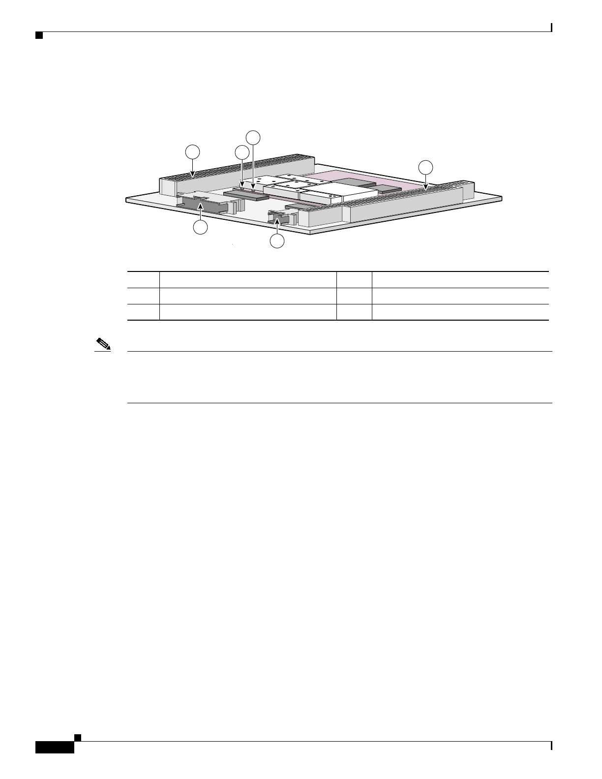
Figure 6-1 shows the WMIC header and bus locations.
Figure 6-1 WMIC Header and Bus Locations
Note The PC/104-Plus standard requires that the PCI bus and the ISA bus utilize keying features in the
standard stacking headers to guarantee proper module installation. On the PCI bus, pin D30 is removed
and the D30 opening is plugged. On the ISA bus, pin C19 and pin B10 are removed, and the C19 and
B10 openings are plugged.
Antenna Connector
On the radio card, there are two ultra-miniature coaxial connectors (U.FL connector) that are used to
connect the coax cables between the WMIC and the external antenna connectors. Two connectors are
used to support antenna diversity.
The cable should be as short as possible to minimize the loss in strength of the radio frequency (RF)
signal. The cable carries the RF signal from the antenna to the low noise amplifier (LNA) on the receiver
and transmits the RF signal from power amplifier (PA) to the antenna that radiates the RF signal.
There are many antenna connector families. The Cisco RP-TNC antenna connector can be used to
support standard antennas.
WMIC Console and Fast Ethernet Ports
Cisco 3200 Series router cards do not support any ISA bus signals. The PCI bus connector supports
communication between Cisco 3200 Series router card and the Fast Ethernet Switch Mobile Interface
Card (FESMIC) and Serial Mobile Interface Card (SMIC).
In a Cisco rugged enclosure, the WMIC communicates with the router through the WMIC Fast Ethernet
interface. The WMIC Fast Ethernet ports are connected internally to Fast Ethernet ports that provide a
communications link with the router.
1PCI bus 2Left antenna connector (J2)
3Right antenna connector (J1) 4ISA bus
510-pin Fast Ethernet header 624-pin multifunction header
103981
4
2
1
3
5
6

6-3
Cisco 3200 Series Router Hardware Reference
OL-5816-09
Chapter 6 Wireless Mobile Interface Cards (WMICs)
The WMIC interfaces are configured through a WMIC console port. In contrast, the Serial Mobile
Interface Card (SMIC) and FESMIC communicate with the router through the PC/104-Plus bus. The
interfaces are configured through the router console port, and all of the router and FESMIC Fast Ethernet
ports are identified by using the slot/port format.
The WMIC runs an independent IOS image and when it is configured, the link between the WMIC and
the router forms an internal LAN. In standard configurations, a WMIC Fast Ethernet port is never
brought out to the end cap.
The WMIC console port is brought out to the corresponding RJ-45 port on the I/O end cap, replacing a
Fast Ethernet port. If the router includes one WMIC, the RS-232 WMIC console port replaces a Fast
Ethernet port on the end cap. If the router includes two WMICs, two WMIC RS-232 console ports
replace two Fast Ethernet ports on the end cap.
Note Currently, even if the router contains zero WMICs, in standard configurations a maximum of three Fast
Ethernet ports are brought out to the end cap. Unused RS-232 ports are sealed.
Fast Ethernet Signals on the WMIC
The Fast Ethernet signals are delivered through a 10-pin header. LED signals and RS-232 console signals
are provided through the 24-pin multifunction header.
There is one set of fixed Fast Ethernet signals on the WMIC. The Fast Ethernet port signals are in
compliance with IEEE 802.3. They are provided through the Ethernet headers, which support the
following:
•Auto-negotiation for 10/100BASE-TX connection
•Full-duplex and half-duplex modes
•Low-power sleep mode
•10BASE-T and 100BASE-TX using a single Ethernet connection
•Robust baseline wander correction performance
•Standard carrier signal multiple access collision detect (CSMA/CD) or full-duplex operation
•Integrated LED drivers
Note If Auto-MDIX is disabled, when connecting to Ethernet switches or repeaters a straight-through cable
can be used. When connecting to compatible workstations, servers, and routers, a crossover cable should
be used. If Auto-MDIX is enabled, either a straight-through or crossover cable can be used can be used
to make the connection, as the router automatically changes the signals on the pins to compensate.

6-4
Cisco 3200 Series Router Hardware Reference OL-5816-09
Chapter 6 Wireless Mobile Interface Cards (WMICs)
LED Behavior
During normal operations, the indicator signals on the wireless device have the following meanings.
•The status indicator signals operational status. Steady green indicates that the wireless device is
associated with at least one wireless client. Blinking green indicates that the wireless device is
operating normally but is not associated with any wireless devices.
•The radio indicator blinks green to indicate radio traffic activity. The light is normally off, but it
blinks whenever a packet is received or transmitted over the radio.
•The Ethernet indicator signals traffic on the wired LAN. This indicator is normally green when an
Ethernet cable is connected, and blinks green when a packet is received or transmitted over the
Ethernet infrastructure. The indicator is off when the Ethernet cable is not connected.
Table 6-1 shows the details of LED behavior.
Table 6-1 Indicator Signals
Message
type Ethernet
indicator Status
indicator Radio
indicator Meaning
Boot loader
status Green – Green DRAM memory test.
– Amber Red Board initialization test.
– Blinking
green Blinking
green Flash memory test.
Amber Green – Ethernet initialization test.
Green Green Green Starting Cisco IOS software.
Association
status – Green – At least one wireless client device is
associated with the unit.
– Blinking
green – No client devices are associated; check the
wireless device SSID and WEP settings.
Operating
status – Green Blinking
green Transmitting/receiving radio packets.
Green – – Ethernet link is operational.
Blinking
green – – Transmitting/receiving Ethernet packets.
Boot Loader
Errors Red – Red DRAM memory test failure.
– Red Red File system failure.
Red Red – Ethernet failure during image recovery.
Amber Green Amber Boot environment error.
Red Green Red No Cisco IOS image file.
Amber Amber Amber Boot failure.

6-5
Cisco 3200 Series Router Hardware Reference
OL-5816-09
Chapter 6 Wireless Mobile Interface Cards (WMICs)
Key Features
The key features of the Cisco wireless devices are listed in Table 6-2.
Operation
Errors – Green Blinking
amber Maximum retries or buffer full occurred on
the radio.
Blinking
amber – – Transmit/receive Ethernet errors.
– Blinking
amber – General warning.
Configuration
Reset – Amber – Resetting the configuration options to
factory defaults.
Failures Red Red Red Firmware failure; try disconnecting and
reconnecting unit power.
Blinking red – – Hardware failure. The wireless device
must be replaced.
Firmware
Upgrade – Red – Loading new firmware image.
Table 6-1 Indicator Signals (continued)
Message
type Ethernet
indicator Status
indicator Radio
indicator Meaning
Table 6-2 Key Features
Feature Description
Wireless Medium Direct Sequence Spread Spectrum (DSSS)
Orthogonal Frequency Division Multiplexing (OFDM)
Radio Media Access
Protocol Carrier sense multiple access with collision avoidance (CSMA/CA)
SNMP Compliance MIB I and MIB II
Encryption Key Length 128-bit
Quality of Service
(QoS) Support Prioritization of traffic for different requirements, such as voice and video.

6-6
Cisco 3200 Series Router Hardware Reference OL-5816-09
Chapter 6 Wireless Mobile Interface Cards (WMICs)
Security Cisco Wireless Security Suite:
Authentication:
•802.1X support including LEAP, PEAP, EAP-TLS, and EAP-SIM to
yield mutual authentication and dynamic, per-user, per-session WEP
keys
•MAC address and by standard 802.11 authentication mechanisms
Encryption:
•Static and dynamic IEEE 802.11 WEP keys of 40 bits and 128 bits
•802.11i/WPAv2 Advanced Encryption Standard-Counter Mode with
Cipher Block Chaining Message Authentication Code Protocol
(AES-CCMP); 128-bit key length
•Temporal Key Integrity Protocol (TKIP) WEP enhancements: key
hashing (per-packet keying), message integrity check (MIC), and
broadcast key rotation by using WPA TKIP
All WMICs in Root Mode:
PEAP, EAP-TTLS, LEAP, EAP-TLS, EAP-FAST, and EAP-SIM.
Cisco 3201 WMICs in Client Mode:
LEAP, EAP-TLS & EAP-FAST
Cisco 3202 and Cisco 3205 WMICs in Client Mode:
LEAP
Status Indicators LEDs provide information concerning association status, operation,
error/warning, firmware upgrade, and configuration, network/modem, and
radio status
Memory 8 MB Flash
32 MB DRAM
Automatic Configuration
Support BOOTP and DHCP
Remote Configuration
Support Telnet, HTTP, FTP, TFTP, and SNMP
Uplink Auto-sensing 10/100BaseT Ethernet
Local Configuration Console port
Table 6-2 Key Features (continued)
Feature Description

6-7
Cisco 3200 Series Router Hardware Reference
OL-5816-09
Chapter 6 Wireless Mobile Interface Cards (WMICs)
MAC Address Allocation
The WMIC stores one unique MAC address for the BVI interface.
WMIC Power Requirement
In a typical Cisco 3200 Series router configuration, the WMIC draws power from the PCI and the ISA
connectors. Table 6-3 shows the estimated power consumption. Note that these are theoretical maximum
wattages.
Mean Time Between Failure
The calculated Mean Time Between Failure (MTBF) in excess of 1,190,136 hours.
Differences Between WMICs
Table 6-3 WMIC Power Requirement
Voltage Current Draw Power Source
+5.0 V 0.4 amps 2.0 W ISA and PCI connectors
+3.3 V 1.7 amps 5.6 W PCI connectors
Table 6-4 Differences between WMICs
Feature 2.4 GHz (802.11b/g) 4.9 GHz (public safety) 5.0 GHz (802.11h) Comment
Cisco IOS image
release 12.3(8) JK 12.3.(2) JK 12.3.(2) JL
Cookie and banner C3201 C3202 C3205
Frequency 2.4 GHz 4.9 GHz 5.0 GHz
Power Maximum OFDM power
level is 15dbm (30mw),
but the power level might
vary by country.
Maximum OFDM power
level is 17dbm (50mw). The power levels can be
defined as 4 dBm, 7 dBm,
10 dBm, 13 dBm, or
16 dBm.
power client Command Supported Not supported. (Use the
power local command.) Not supported. (Use the
power local command.)
Transmission Power
Control (TPC) Not supported Not supported Supported for ETSI. TPC limits the
transmitted power to
the minimum power
level needed to reach
the furthest user.

6-8
Cisco 3200 Series Router Hardware Reference OL-5816-09
Chapter 6 Wireless Mobile Interface Cards (WMICs)
Dynamic Frequency
Selection (DFS) NA NA Supported for ETSI. DFS selects the radio
channel most likely
to minimize
interference with
military radar.
Channelization Statically declared as
defined by IEEE
802.11b/g.
Channel spacing selected
by using the CLI. Statically declared as
defined by IEEE 802.11h.
(Available only in
Europe.)
Concatenation Supported. Not supported. Not supported.
Fragmentation Maximum threshold is
4000 bytes. Maximum threshold is
2346 bytes. Supported Fragment counter is
in units of
fragmented packets.
distance Command Supported up to 99
kilometers. Supported up to 3
kilometers (1.8 miles). Supported up to 99
kilometers. Minimizes delay
propagation.
Autonomous Modes
Supported Work Group Bridge
(WGB), Non Root Bridge
(NRB), Root Bridge
(RB), Repeater, and
Access Point (AP)
Work Group Bridge
(WGB), Non Root Bridge
(NRB), Root Bridge
(RB), Repeater, and
Access Point (AP)
Work Group Bridge
(WGB), Non Root Bridge
(NRB), Root Bridge
(RB), and Access Point
(AP)
World Mode Supported. Supported only if the
wireless device is in root
access point or root
bridge mode. Not
supported in client
modes.
Supported only if the
wireless device is in root
access point or root
bridge mode. Not
supported in client
modes.
World Mode on the
client side updates a
client with the
channels of the
specified domain.
The Cisco 3200
Series router is
limited to fixed
channels, so
world-mode is not
available on the
client side.
Universal Workgroup
Bridge Mode Supported Not supported Not supported Enables operation
with non-Cisco
access points.
Multiple Client Profiles Supported Not supported Not supported Support is enabled
only when universal
workgroup bridge
mode is enabled.
Multiple Basic SSIDs Supported Not supported Not supported
VLANs 16 unencrypted VLANs,
16 static key VLANs, or
16 dynamic key VLANs,
16 unencrypted VLANs,
1 static key VLAN, or 4
dynamic key VLANs.
16 unencrypted VLANs,
1 static key VLAN, or 4
dynamic key VLANs.
Table 6-4 Differences between WMICs (continued)
Feature 2.4 GHz (802.11b/g) 4.9 GHz (public safety) 5.0 GHz (802.11h) Comment

6-9
Cisco 3200 Series Router Hardware Reference
OL-5816-09
Chapter 6 Wireless Mobile Interface Cards (WMICs)
Wireless
encryption/cipher
suites
WEP-40, WEP-128,
TKIP, CKIP, CMIC and
CKIP-CMIC
WEP-40, WEP-128,
TKIP, and AES-CCM WEP-40, WEP-128,
TKIP, and AES-CCM
Max Number of
Stations with WEP 255 116 116
Max Number of
Stations with TKIP 256 26 26
Max Number of
Stations with
AES-CCM
256 116 116
WDS Server Not supported. Supported Supported
WDS Client Can auto discover and
work with a subnet WDS
server.
Can auto discover and
work with a WDS server
on the same subnet as the
WMIC. If the IP address
of a WDS server is
anywhere on the network
and the IP address is
statically configured on a
WMIC acting as root
device, the WMIC can
work with the WDS
server.
Can auto discover and
work with a WDS server
on the same subnet as the
WMIC. If the IP address
of a WDS server is
anywhere on the network
and the IP address is
statically configured on a
WMIC acting as root
device, the WMIC can
work with the WDS
server.
EAP-TLS, EAP-TTLS EAP-TLS is supported.
EAP-TTLS is supported
on root devices only.
EAP-TLS is supported in
client mode. EAP-TTLS
is not supported.
EAP-TLS is supported in
client mode. EAP-TTLS
is not supported.
EAP-FAST Supported on root and
non-root devices. Not supported Supported on root and
non-root devices.
WDS Server Related
MIBS N/A Supported Supported
Table 6-4 Differences between WMICs (continued)
Feature 2.4 GHz (802.11b/g) 4.9 GHz (public safety) 5.0 GHz (802.11h) Comment

6-10
Cisco 3200 Series Router Hardware Reference OL-5816-09
Chapter 6 Wireless Mobile Interface Cards (WMICs)
2.4 GHz (802.11b/g) WMIC Features
The key features of the 2.4 GHz (802.11b/g) WMIC are listed below.
Fast Roaming
Scanning
Enhancements
All scanning
enhancements for faster
roaming are available.
All scanning
enhancements for faster
roaming are available
except “Use First Better
Access Point.”
All scanning
enhancements for faster
roaming are available
except “Use First Better
Access Point.”
•Synthesizer
tuning time
•Start on current
channel
•Only probe
current SSID
•Shorten wait
time for probe
response
•Automatically
limiting
frequencies
scanned
•Time out the
scan
•Use first better
access point
•Save best probe
response
CCXv4 features Supported Not supported Supported
802.11e MMN QoS Supported Not supported Supported
Simple Network
Management Protocol
(SNMP) MIB IDs
Supported Supported for new values Supported The
platform-dependent
SNMP code was
modified to return
new values
(entPhysicalVendorT
ype, System OID,
and Chassis ID).
Dot11 MIB parameters Supported The dot11 parameters are
returned through the
dot11 MIB interface.
Supported
Table 6-4 Differences between WMICs (continued)
Feature 2.4 GHz (802.11b/g) 4.9 GHz (public safety) 5.0 GHz (802.11h) Comment
Data Rates Supported 1, 2, 5.5, 6, 9, 11, 12, 18, 24, 36, 48, and 54 Mbps
Network Standard IEEE 802.11b and IEEE 802.11g

6-11
Cisco 3200 Series Router Hardware Reference
OL-5816-09
Chapter 6 Wireless Mobile Interface Cards (WMICs)
The channel identifiers, channel center frequencies, and regulatory domains of each IEEE 802.11b/g
22-MHz-wide channel are shown in Table 6-5.
Frequency Band 2.400 GHz to 2.497 GHz
Modulation BPSK 1 Mbps and 6 Mbps
QPSK 2 Mbps and 12 Mbps
CCK 5.5 Mbps
BPSK 9.6 Mbps
CCK2 11 Mbps
QPSK 18 Mbps
16 QAM 24 Mbps and 36 Mbps
64 QAM 48 Mbps and 54 Mbps
Operating Channels North America: 11; ETSI: 13; Japan: 14
Receive Sensitivity 1 Mbps: -94 dBm
2 Mbps: -91 dBm
5.5 Mbps: -89 dBm
11 Mbps: -85 dBm
Transmit Power Settings 100 mW (20 dBm)
50 mW (17 dBm)
30 mW (15 dBm)
20 mW (13 dBm)
5 mW (7 dBm)
1 mW (0 dBm)
Maximum power setting vary to comply with the regulatory domain.
Range (typical @ 100 mW
transmit power setting
with 6 dBi diversity dipole
antenna)
Outdoor:
0.5 mile (804 m) @ 45 Mbps
1 mile (1609 m) @ 11 Mbps
3 miles (4,827 m) @ 1 Mbps
Compliance 2.4 GHz (802.11b/g) operates license free under FCC Part 15 and complies
as a Class B device; complies with DOC regulations; complies with ETS
300.328, FTZ 2100, and MPT 1349 standards; rugged version complies with
UL 2043
Table 6-5 Channels for IEEE 802.11b/g
Channel
Identifier
Center
Frequency
(MHz)
Regulatory Domains
Americas (–A) EMEA (–E) Japan (–J)
CCK OFDM CCK OFDM CCK OFDM
1 2412 X X X X X X
2 2417 X X X X X X
3 2422 X X X X X X
4 2427 X X X X X X

6-12
Cisco 3200 Series Router Hardware Reference OL-5816-09
Chapter 6 Wireless Mobile Interface Cards (WMICs)
Universal Workgroup Bridge Limitations
The following limitations and restrictions apply to universal workgroup bridges:
•A universal workgroup bridge can not associate with the Cisco WLAN AP with CKIP or CMIC
encryption configuration.
•If the universal workgroup bridge is associated with a Cisco AP or third party AP and if the user
issues the command show dot11 association all, the IP address and name information is not
available.
•Users should configure the static IP address on the BVI when it is in the universal workgroup bridge
mode, so that the WMIC is manageable from the MAR through the Mobile IP tunnel from the
infrastructure side.
•If the dynamic CCoA is used on the Cisco 3200 Series Wireless and Mobile Router, you should
configure the static IP address using the ip secondary address command.
•The universal workgroup bridge is not compatible with the Tropos version 3.1.1.2 AP.
•A universal workgroup bridge can not associate with the Cisco 1500 router when it is configured
with the Allow WPA2 TKIP Clients option.
5 2432 X X X X X X
6 2437 X X X X X X
7 2442 X X X X X X
8 2447 X X X X X X
9 2452 X X X X X X
10 2457 X X X X X X
11 2462 X X X X X X
12 2467 – – X X X X
13 2472 – – X X X X
14 2484 – – – – X –
Table 6-5 Channels for IEEE 802.11b/g (continued)
Channel
Identifier
Center
Frequency
(MHz)
Regulatory Domains
Americas (–A) EMEA (–E) Japan (–J)
CCK OFDM CCK OFDM CCK OFDM

6-13
Cisco 3200 Series Router Hardware Reference
OL-5816-09
Chapter 6 Wireless Mobile Interface Cards (WMICs)
4.9 GHz (public safety) WMIC Features
The key features of the 4.9 GHz (public safety) WMIC are listed in Table 6-6.
4.9 GHz Channels
Table 6-7 shows the channel options for the 4.94 GHz to 4.99 GHz band for the United States regulatory
domain.
Table 6-6 Key Features of the 4.9 GHz (public safety) WMIC
Feature Description
Data Rates Supported 5 MHz channelization: 1.5, 2.25, 3, 4.5, 6, 9, 12, and 13.5 Mbps
10 MHz channelization: 3, 4.5, 6, 9, 12, 18, 24, and 27 Mbps
20 MHz channelization: 6, 9, 12, 18, 24, 36, 48, and 54 Mbps
Network Standard Currently there is no IEEE 4.9 GHz (public safety) standard; however, it is
similar to the IEEE 802.11a standard.
Frequency Band 4.940 GHz to 4.990 GHz
Available Transmit Power
Settings 50 mW (17 dBm)
40 mW (16 dBm)
30 mW (15 dBm)
20 mW (13 dBm)
10 mW (10 dBm)
5 mW (7 dBm)
Compliance 4.9 GHz (public safety):
•Operation restricted to operators meeting requirements of CFR47 Part
90.20 of the technical rules for qualification as a Public Safety operator.
•Requires a FCC license to operate under this part of the Part 90
Regulation
Table 6-7 FCC 4.9 Operational Channels as per TIA TR-8 Specification
Operating Channel
Numbers Channel Center 5 MHz
Channel Spacing Channel Center 10 MHz
Channel Spacing Channel Center 20 MHz
Channel Spacing
1
3
5 4942.5
7
9
10 4945.0
15 4947.5
20 4950.0 4950.0
25 4952.5
30 4955.0 4955.0

6-14
Cisco 3200 Series Router Hardware Reference OL-5816-09
Chapter 6 Wireless Mobile Interface Cards (WMICs)
Note Channel Center Frequencies (MHz) 1 MHz Channel Spacing is documented in the TIA TR-8
specification, but it is not supported by the 4.9 GHz (public safety) WMIC.
Throughput
The throughput is a minimum of:
•4 Mbps half-duplex at one mile line-of-sight for a 5 MHz-wide channel
•8 Mbps half-duplex at one mile line-of-sight range for a 10 MHz-wide channel.
•16 Mbps half-duplex at one mile line-of-sight range for a 20 MHz-wide channel.
Modulation
Table 6-8 shows the modulation.
35 4957.5
40 4960.0 4960.0
45 4962.5
50 4965.0 4965.0
55 4967.5
60 4970.0 4970.0
65 4972.5
70 4975.0 4975.0
75 4977.5
80 4980.0 4980.0
85 4982.5
90 4985.0
91
93
95 4987.5
97
99
Table 6-7 FCC 4.9 Operational Channels as per TIA TR-8 Specification (continued)
Operating Channel
Numbers Channel Center 5 MHz
Channel Spacing Channel Center 10 MHz
Channel Spacing Channel Center 20 MHz
Channel Spacing
Table 6-8 Modulation
Modulation 5 Mbps 10 Mbps 20 Mbps
BPSK 1.5 Mbps and 2.25 Mbps 3 Mbps and 4.5 Mbps 6 Mbps and 9 Mbps
QPSK 3 Mbps and 4.5 Mbps 6 Mbps and 9 Mbps 12 Mbps and 18 Mbps

6-15
Cisco 3200 Series Router Hardware Reference
OL-5816-09
Chapter 6 Wireless Mobile Interface Cards (WMICs)
Receive Sensitivity
Table 6-9 shows the receive sensitivity.
5.0-GHz (802.11h) Radio Features
The radio supports only 20-MHz channelization.
Note 802.11h is supported only in the ETSI regulatory domain.
Note By default, the C3205 WMIC uses the right antenna to receive and transmit data.
5.0-GHz (802.11h) Channels
The 5.0-GHz (802.11h) radio in the Cisco 3200 Series router (currently available as the Cisco 3205
WMIC) supports the following channels/frequencies in the ETSI regulatory domain:
•5.250 GHz to 5.350 GHz: 5260 MHz (52), 5280 MHz (56), 5300 MHz (60), 5320 MHz (64),
•5.470 GHz to 5.725 GHz: 5500 MHz (100), 5520 MHz (104), 5540 MHz (108), 5560 MHz (112),
5580 MHz (116), 5600 MHz (120), 5620 MHz (124), 5640 MHz (128), 5660 MHz (132),
5680 MHz (136), 5700 MHz (140). (Channels 52 through 140 are ETSI outdoor channels.)
16 QAM 6 Mbps and 9 Mbps 12 Mbps and 18 Mbps 24 Mbps and 27 Mbps
64 QAM 12 Mbps and 13.5 Mbps 24 Mbps and 27 Mbps 48 Mbps and 54 Mbps
Table 6-8 Modulation (continued)
Modulation 5 Mbps 10 Mbps 20 Mbps
Table 6-9 Receive Sensitivity
5 MHz 10 MHz 20 MHz
1.5 Mbps -89 dBm 3 Mbps -87 dBm 6 Mbps -85 dBm
2.25 Mbps -89 dBm 4.5 Mbps -87 dBm 9 Mbps -85 dBm
3 Mbps -89 dBm 6 Mbps -87 dBm 12 Mbps -85 dBm
4.5 Mbps -85 dBm 9 Mbps -87 dBm 18 Mbps -82 dBm
6 Mbps -82 dBm 12 Mbps -85 dBm 24 Mbps -79 dBm
9 Mbps -79 dBm 18 Mbps -79 dBm 36 Mbps -76 dBm
12 Mbps -74 dBm 24 Mbps -74 dBm 48 Mbps -71 dBm
13.5 Mbps -72 dBm 27 Mbps -72 dBm 54 Mbps -69 dBm

6-16
Cisco 3200 Series Router Hardware Reference OL-5816-09
Chapter 6 Wireless Mobile Interface Cards (WMICs)
Note By default, the C3205 WMIC performs automatic channel selection on the radio interface. For more
information about configuring a channel on the radio interface of the C3205 WMIC using the
command-line interface (CLI), refer to the “Configuring the Radio Channel or Frequency for the C3205
WMIC” section in the Radio Channels and Transmit Frequencies document. The show interface d0 dfs
command provides DFS statistics.
Throughput
The throughput is a minimum of 16 Mbps half-duplex at one mile line-of-sight range for a
20 MHz-wide channel. The range performance is dependent on output power, antenna gain,
path loss, and other factors.
The following are range performance estimations:
•6 Mbps at 10 kilometers (6 miles) at 30 dBm EIRP
•1 Mbps at 30 kilometers (18 miles) at 30 dBm EIRP
Modulation
Table 6-10 shows the 5.0-GHz (802.11h) modulation.
Receive Sensitivity
Table 6-11 shows the receive sensitivity for all locations.
Table 6-10 5.0-GHz (802.11h) Modulation
Modulation 20 Mbps
BPSK 6 Mbps and 9 Mbps
QPSK 12 Mbps and 18 Mbps
16 QAM 24 Mbps and 27 Mbps
64 QAM 48 Mbps and 54 Mbps
Table 6-11 Receive Sensitivity for 5.0-GHz (802.11h) Radios
Data Rates 5.25 GHz to 5.35 GHz 5.47 GHz to 5.725 GHz 5.725 GHz to 5.825 GHz1
1. The 5.725-GHz to 5.825-GHz range is not supported on European models.
6 Mbps -85 dBm -85 dBm -85 dBm
9 Mbps -85 dBm -85 dBm -85 dBm
12 Mbps -85 dBm -85 dBm -85 dBm
18 Mbps -82 dBm -82 dBm -82 dBm
24 Mbps -79 dBm -79 dBm -79 dBm
36 Mbps -76 dBm -76 dBm -76 dBm
48 Mbps -71 dBm -71 dBm -71 dBm
54 Mbps -69 dBm -69 dBm -69 dBm

6-17
Cisco 3200 Series Router Hardware Reference
OL-5816-09
Chapter 6 Wireless Mobile Interface Cards (WMICs)
Transmit Sensitivity
Table 6-12 shows the transmit sensitivity.
Additional cards and components provide power and link interfaces to the WMIC. The exact
configuration of your router will vary, depending on how it was configured by the vendor.
Related Documentation
These documents provide detailed information regarding the configuration of the wireless card:
•Cisco IOS Switching Services Configuration Guide. Click this link to browse to this document:
http://www.cisco.com/univercd/cc/td/doc/product/software/ios122/122cgcr/fswtch_c/index.htm
•Cisco Internetwork Design Guide. Click this link to browse to this document:
http://www.cisco.com/univercd/cc/td/doc/cisintwk/idg4/index.htm
•Cisco Internetworking Technology Handbook. Click this link to browse to this document:
http://www.cisco.com/univercd/cc/td/doc/cisintwk/ito_doc/index.htm
•Cisco Internetworking Troubleshooting Guide. Click this link to browse to this document:
http://www.cisco.com/univercd/cc/td/doc/cisintwk/itg_v1/index.htm
Table 6-12 Transmit Power Levels for the C3205 WMIC
Data Rates 5.25 GHz to 5.35 GHz 5.47 GHz to 5.725 GHz 5.725 GHz to 5.825 GHz1
1. The 5.725-GHz to 5.825-GHz range is not supported on European models.
6 Mbps 16 dBm 16 dBm 16 dBm
9 Mbps 16 dBm 16 dBm 16 dBm
12 Mbps 16 dBm 16 dBm 16 dBm
18 Mbps 16 dBm 16 dBm 16 dBm
24 Mbps 16 dBm 16 dBm 16 dBm
36 Mbps 16 dBm 16 dBm 16 dBm
48 Mbps 14 dBm 14 dBm 14 dBm
54 Mbps 13 dBm 13 dBm 13 dBm

6-18
Cisco 3200 Series Router Hardware Reference OL-5816-09
Chapter 6 Wireless Mobile Interface Cards (WMICs)