Cisco Systems BTS-R3 Broadband Data BTS User Manual Appendix Pt 1 40 00047 08 F I C TTA
Cisco Systems, Inc Broadband Data BTS Appendix Pt 1 40 00047 08 F I C TTA
UserManual.wiki
>
Cisco Systems
>
BTS-R3 User Manual
>
Manual app 1
Contents
1.
Manual app 1
2.
Manual app 2
3.
Manual 1
4.
Manual 2
5.
Manual 3
6.
Manual 4
7.
Manaul 5
8.
Manual 6
9.
Manual 7
10.
Guide 1
11.
Guide 2
Manual app 1
Navigation menu
Upload a User Manual
Namespaces
Wiki Guide
HTML
PDF
Info
Views
User Manual
Discussion / Help
Navigation
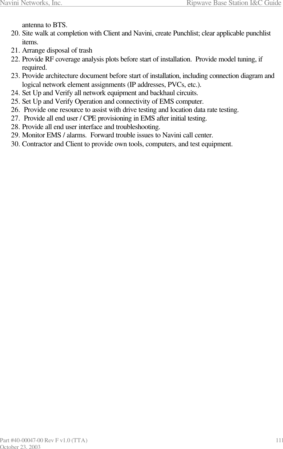


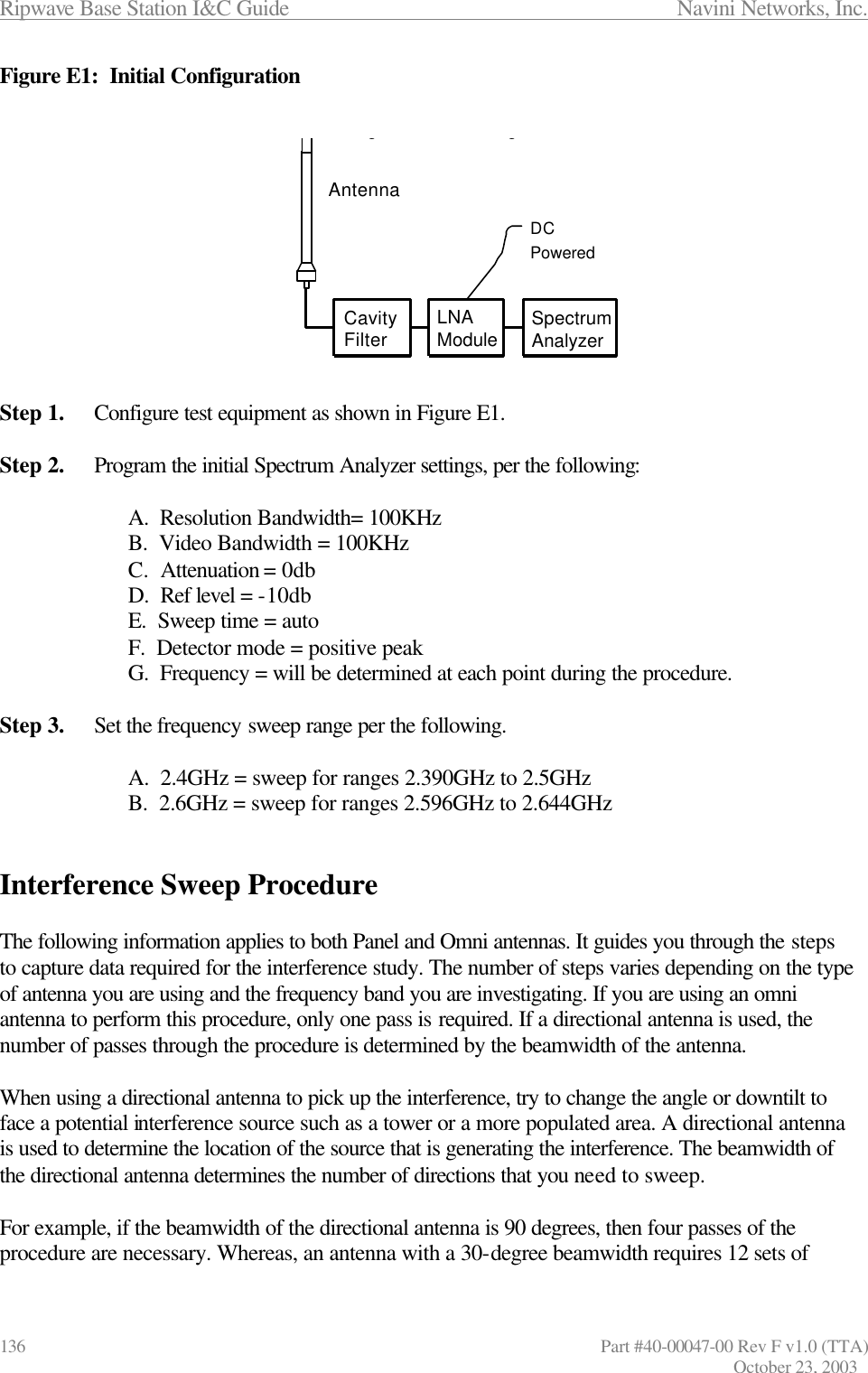
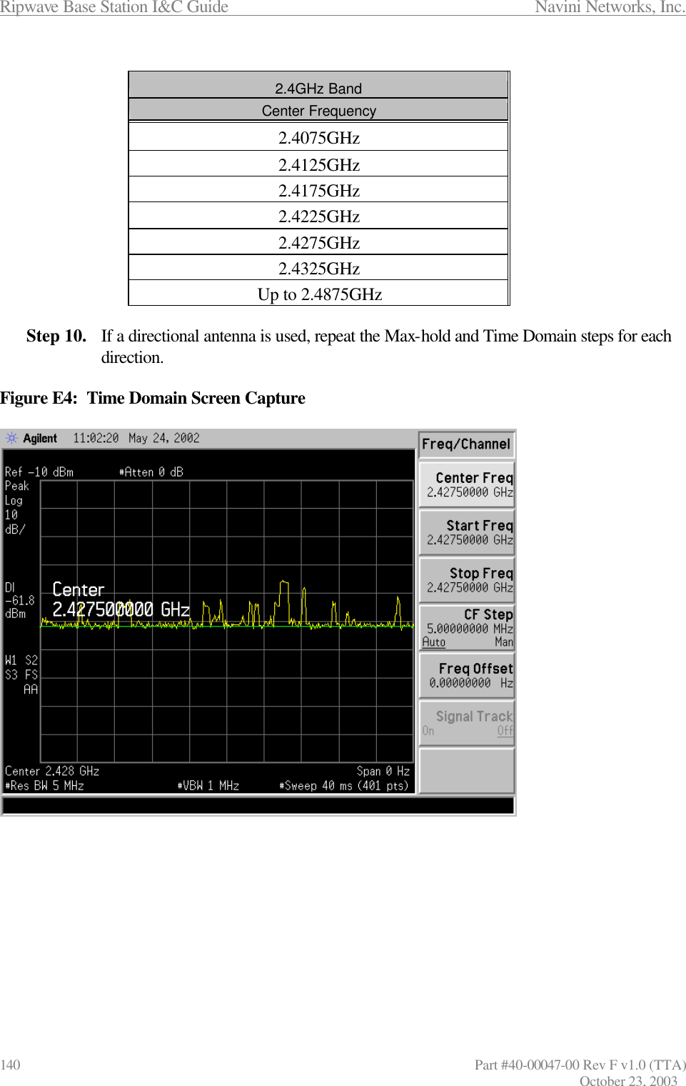
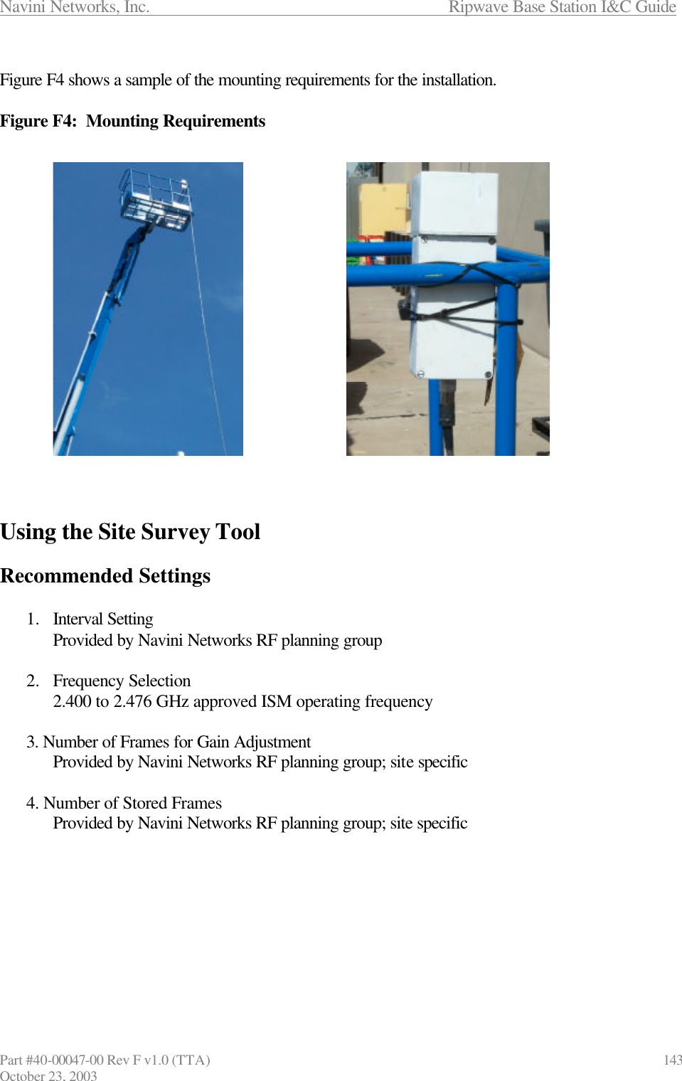
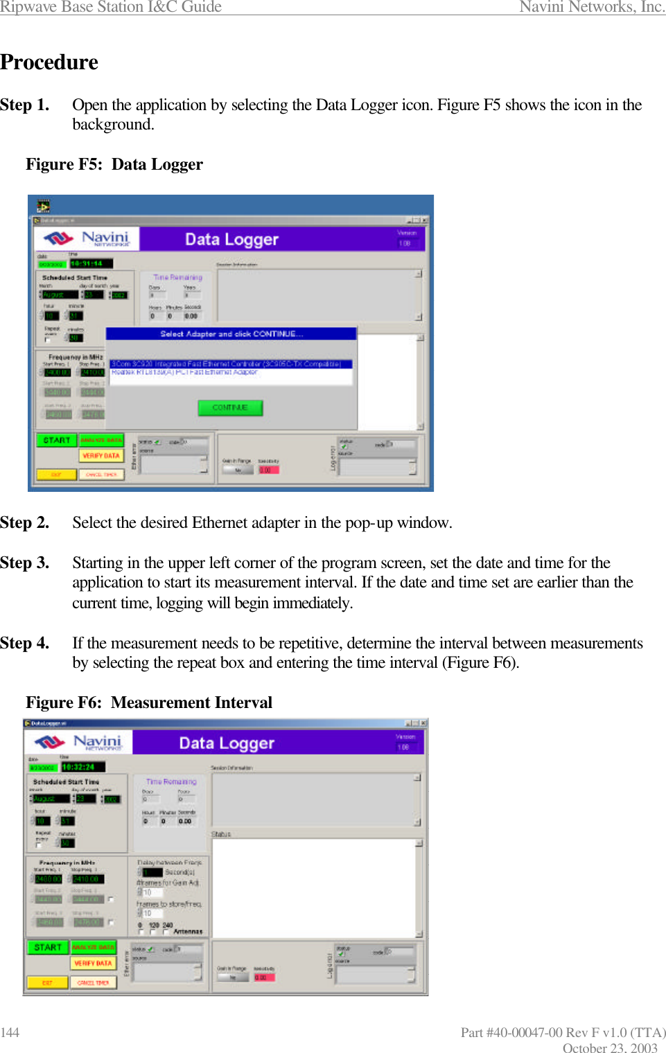
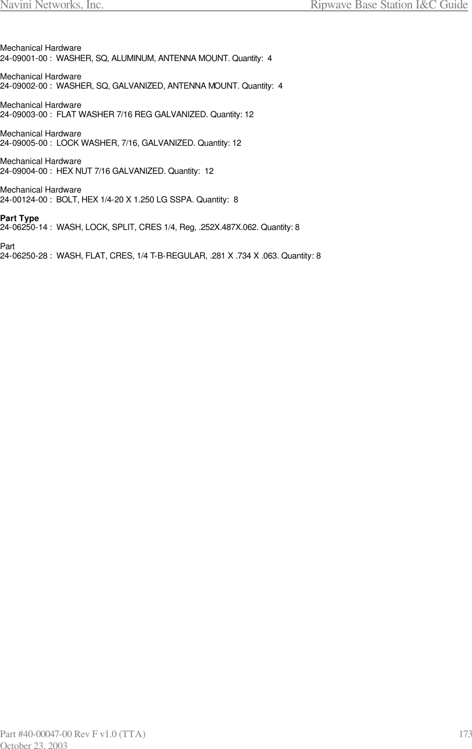
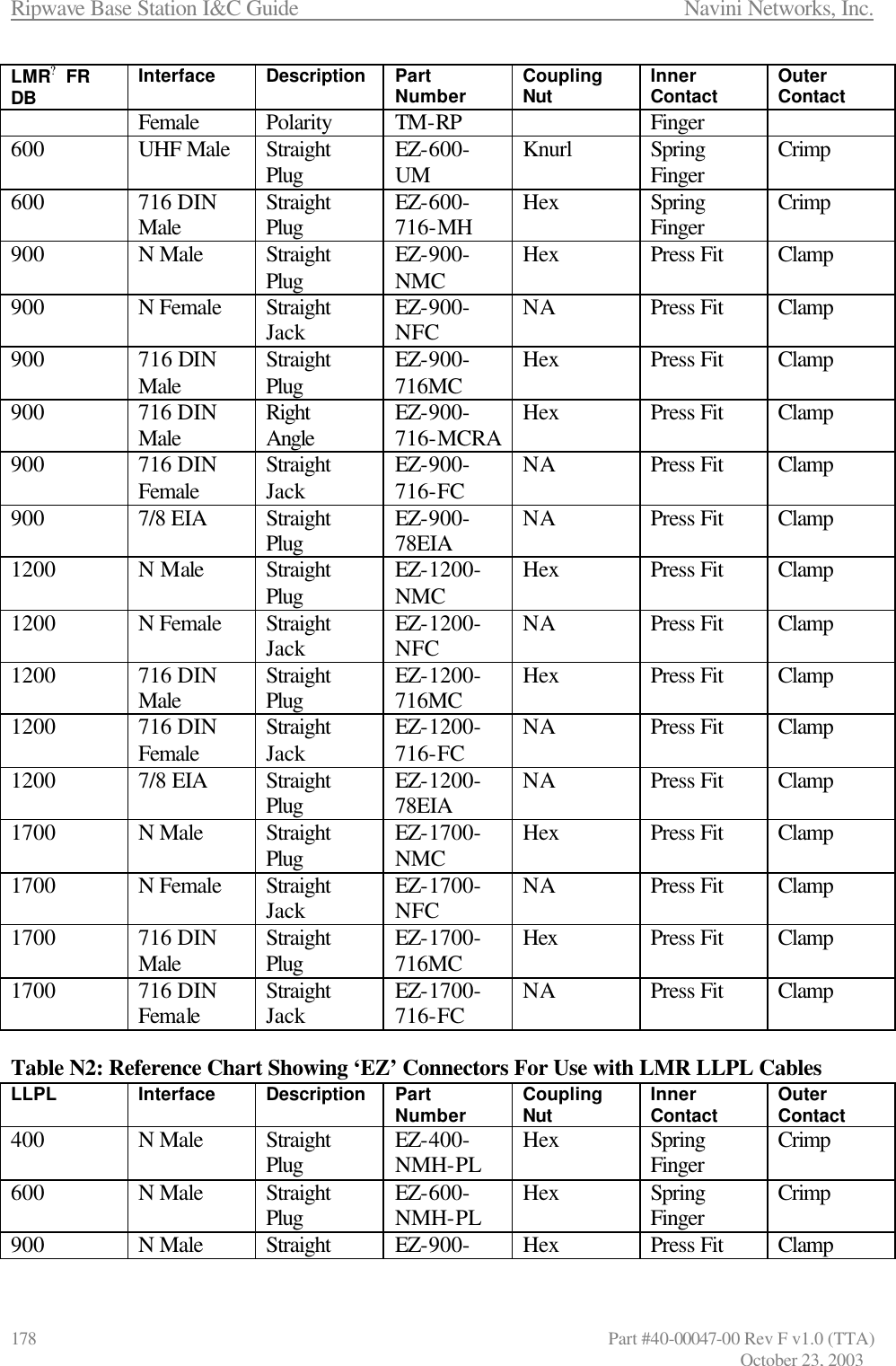
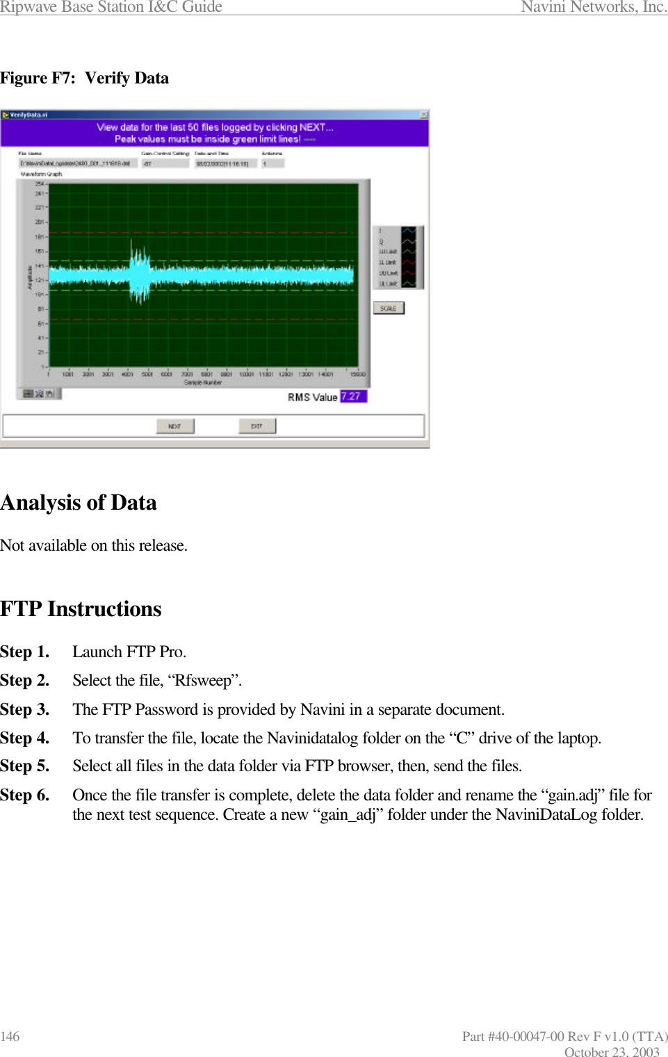
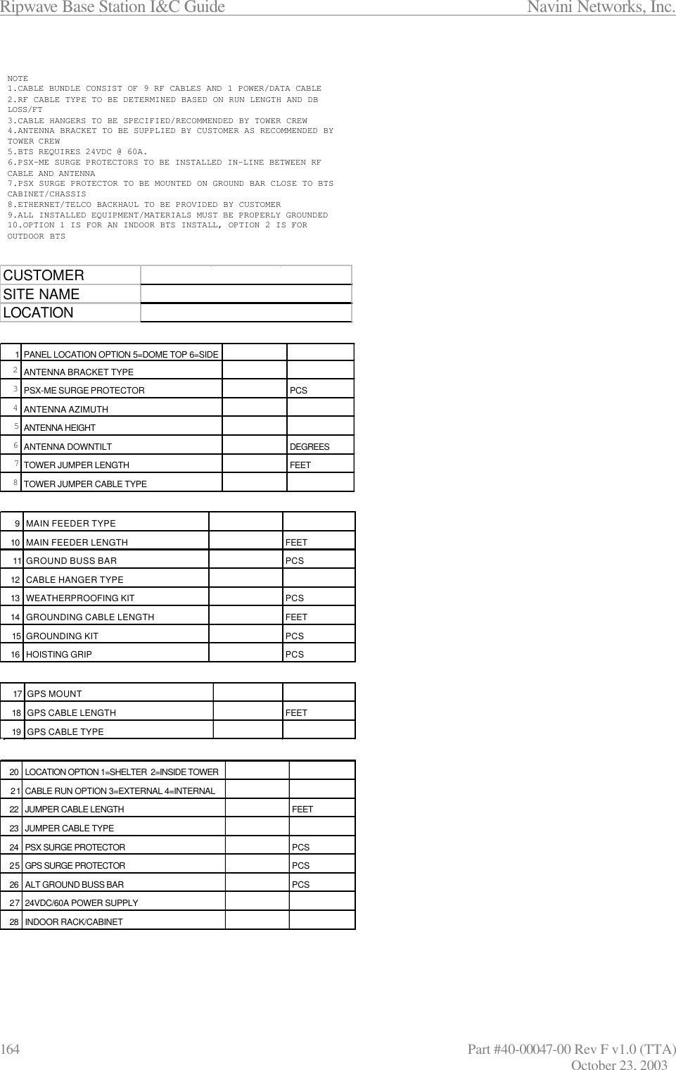
![Navini Networks, Inc. Ripwave Base Station I&C Guide Part #40-00047-00 Rev F v1.0 (TTA) 145 October 23, 2003 Step 5. Select the frequencies to be measured. a. There are 3 frequency band selections. By default two are not available until selected by clicking on the white checkboxes to the right of each. b. If you select more than one band, it is best if you put in some delay between each band’s measurements, as mentioned in Step 6 below. Step 6. If more than one frequency band has been selected, choose the delay to be used between each band’s measurements. You can use the scroll bar or just type in the interval. Step 7. Select the number of frames for Gain Adjust. This allows the system to calculate the Modem’s receiver sensitivity. Step 8. Select the number of frames to be stored for analysis. The same number will be captured for each frequency band if more than one is selected. Step 9. Ensure antenna orientation is selected properly. It takes about 1 second to log one frame of data. Therefore: Elapsed time = #antSelected ? [(number_of_gain_adj Frames) ? n + (Freq_Range/2) ? #of_framesToLog + (Freq_Range/2) ? delayBetweenFreqs] Where n is the number of gain adjustment loops. Up to 10 are possible if the received signal varies to a great extent in amplitude from frame to frame. Step 10. Select the Start button. Step 11. Enter in the desired Site Name in the pop-up window, and press Enter to start the measurements. Step 12. To stop the measurement, select the Abort button. Step 13. PC and Test operation should be validated every 3-4 hours for working order. To Verify the Data Step 1. Click the Verify Data button. The screen shown in Figure F7 appears. The last 50 data files logged can be viewed with this screen. Click on NEXT to view the next file.](https://usermanual.wiki/Cisco-Systems/BTS-R3.Manual-app-1/User-Guide-386809-Page-37.png)


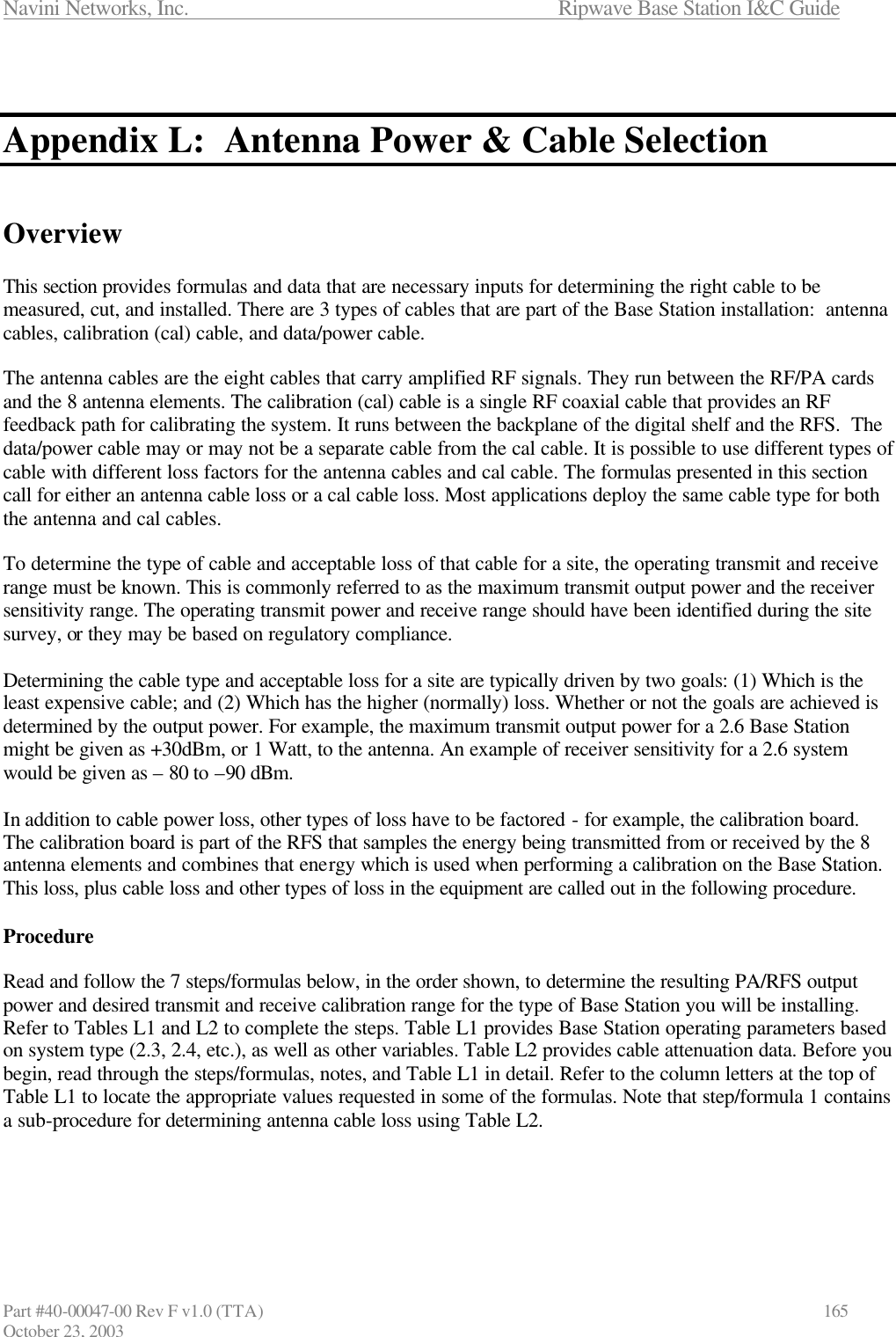
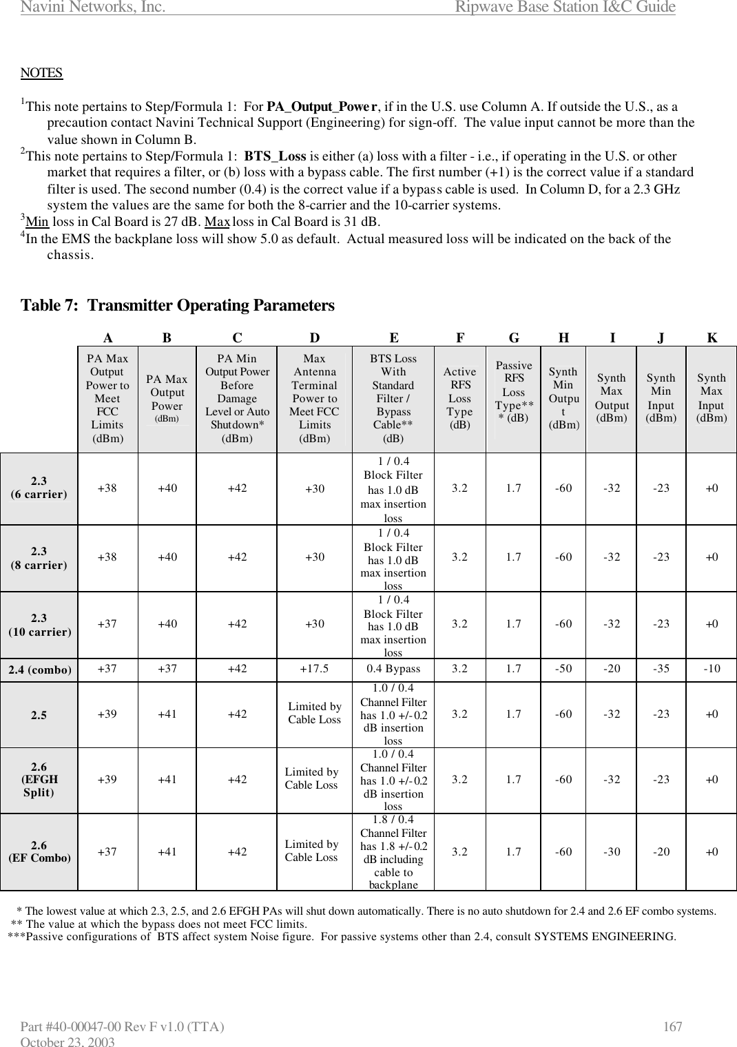
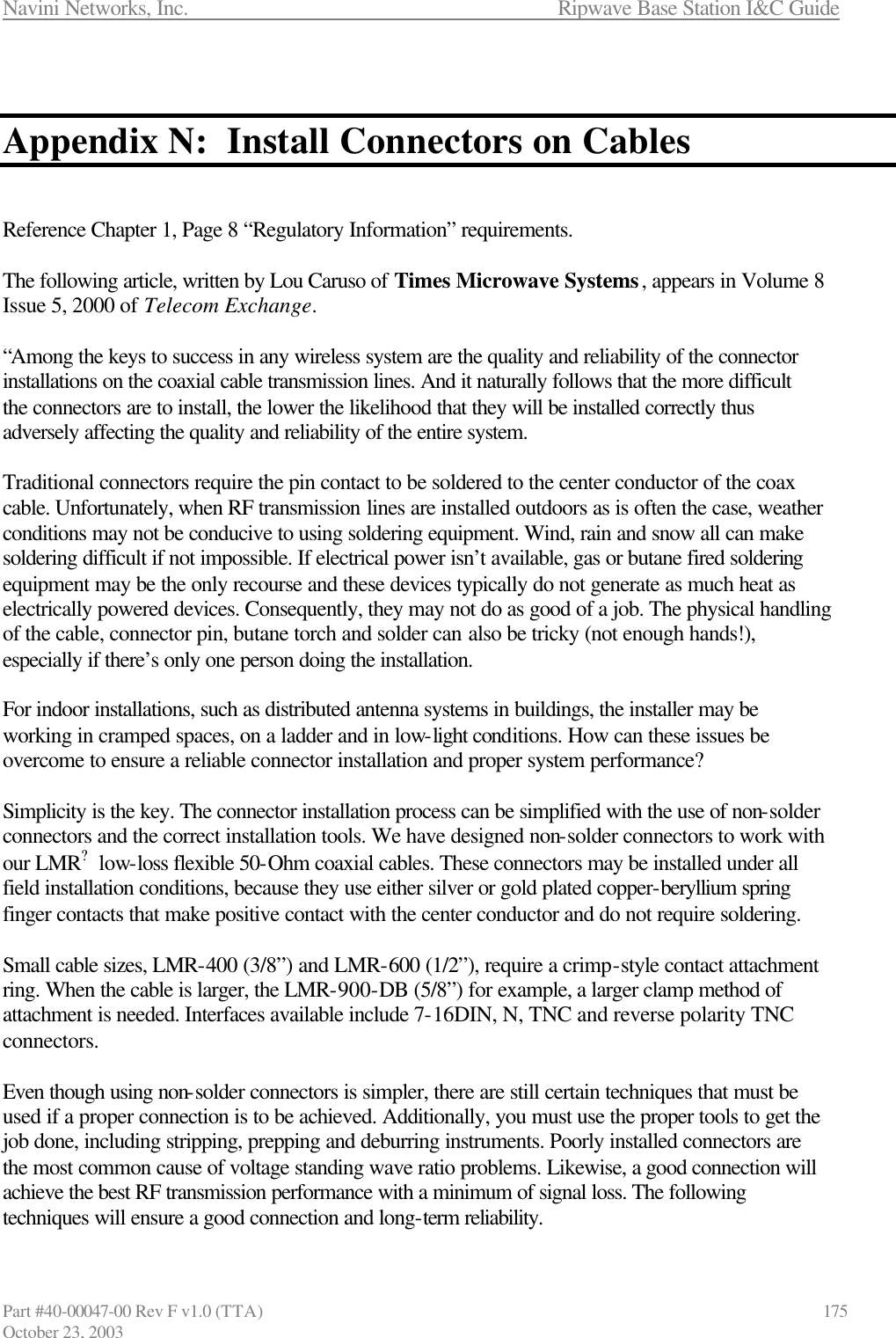
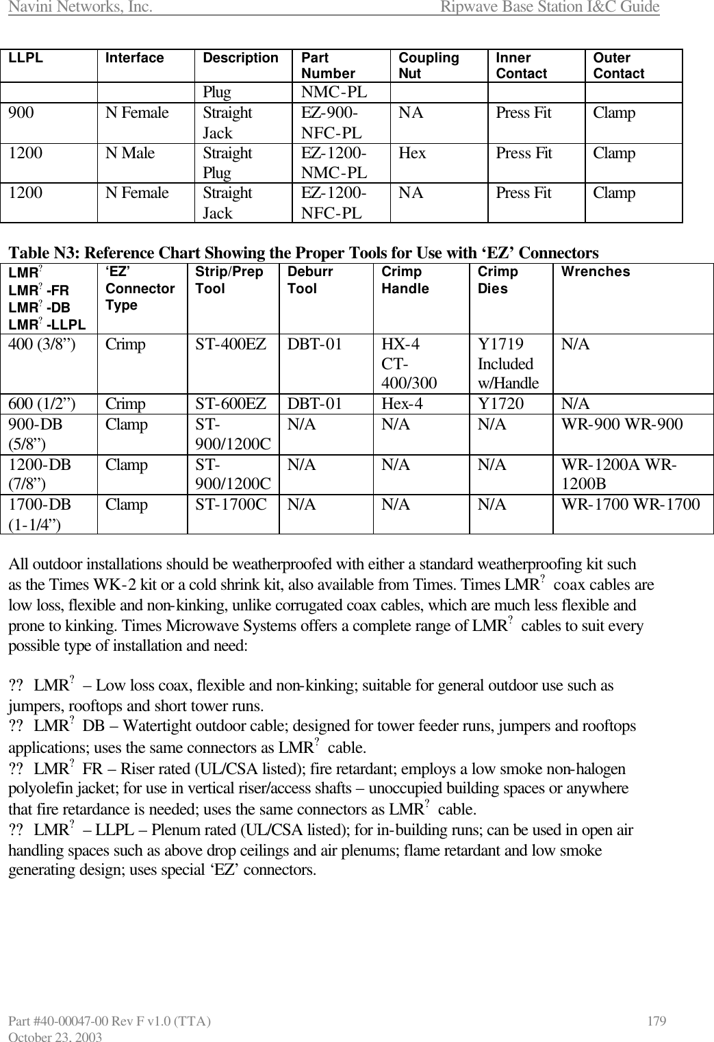
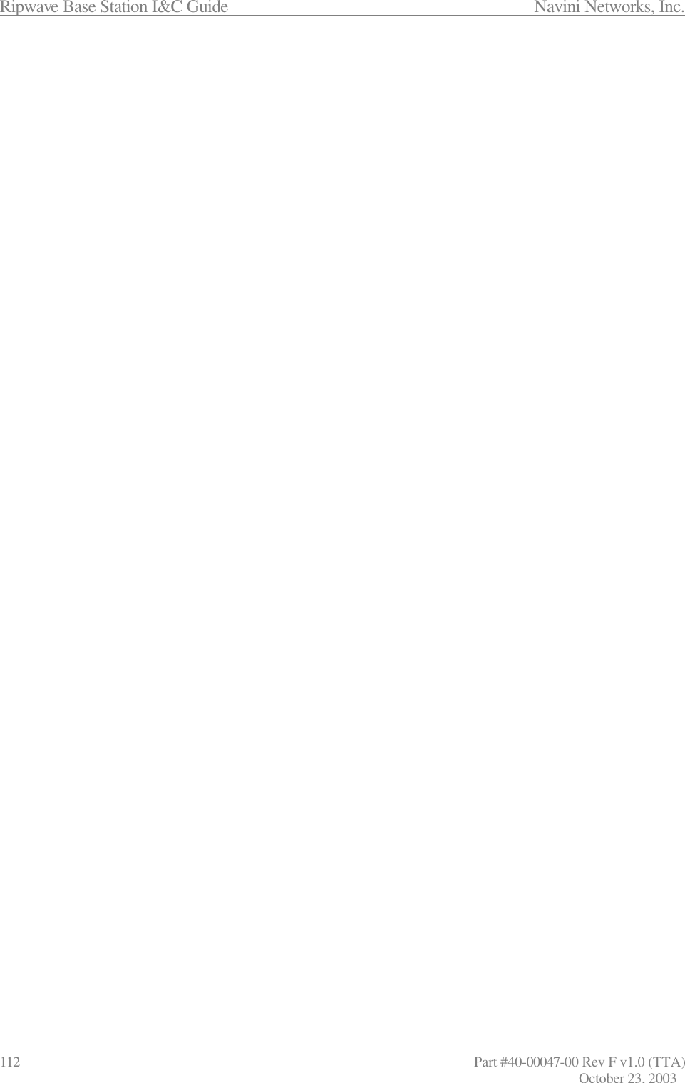
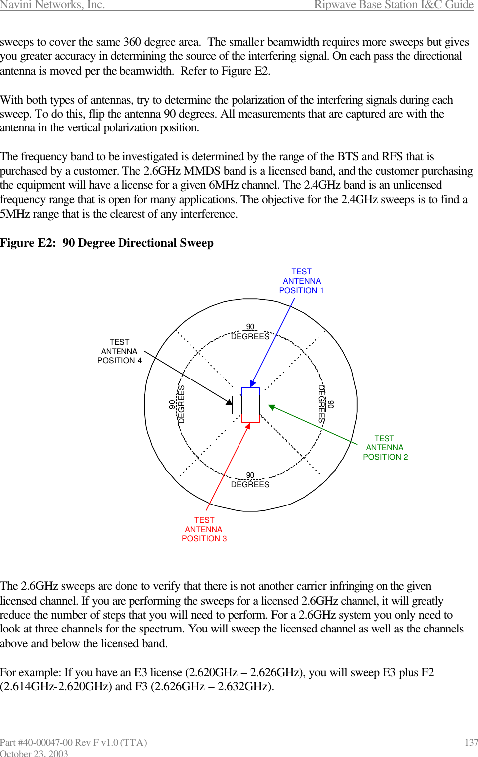
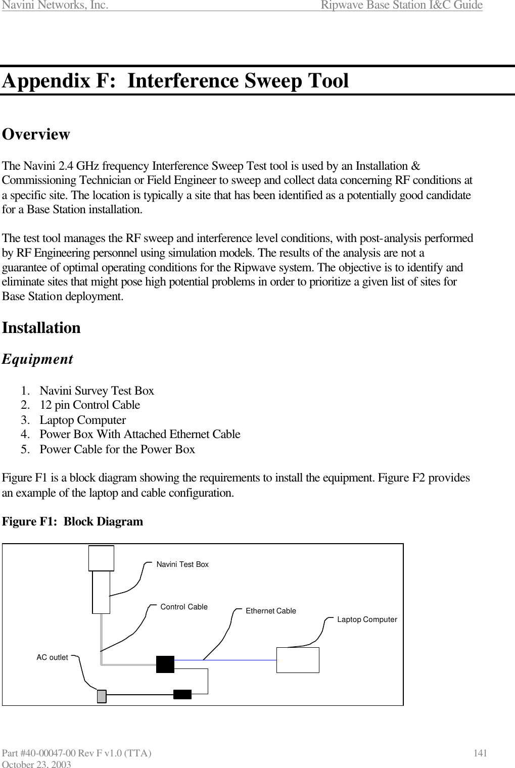
![Ripwave Base Station I&C Guide Navini Networks, Inc. 166 Part #40-00047-00 Rev F v1.0 (TTA) October 23, 2003 Determine the maximum capable BTS output power to the antenna. = [(PA Output to Meet FCC) or (to Meet SNR)] – BTS Loss – RFS Loss – BTS Antenna Cable Loss* [Column A or B]1 – [Column E]2 – [Column F or G] – [Calculated* or Measured] ?? BTS Antenna Cable loss < 18 dB for ACTIVE RFS configurations ?? BTS Antenna Cable loss < 8 dB for PASSIVE RFS configurations Change the EMS settings accordingly. *Sub-procedure: Calculate BTS antenna cable loss, referring to Table 8. = [[Distance (length in ft) 100 ft] x Attenuation value/cable type] + 0.6 for 6 connectors/3 cables Determine the maximum BTS output power that can be calibrated. = Max Synth Input + Cal Cable Loss + Min Cal Board Loss3 + Backplane Loss4 [Column K] + [Calculated or Measured] + [Note 3] + [Default of 5.0 in EMS or Measured] Determine the actual** max BTS output power available to the antenna. = The lesser of the two values of Step/Formula 1 and Step/Formula 2 (aka, the “floor”) ** Actual is what you can calibrate the BTS at. Determine the minimum BTS output power that can be calibrated . = Min Synth Input + Cal Cable Loss + Max Cal Board Loss3 + Backplane Loss4 [Column J] + [Calculated or Measured] + [Note 3] + [Default of 5.0 in EMS or Measured] Determine the actual** maximum EIRP. = Step/Formula 3 + Antenna Gain. The antenna gain is affected by the type of antenna (omni, panel, 2.3, 2.4, etc.) and refers to the values in the RFS Configuration Script that accompanied the antenna from Manufacturing. **Actual is what you can calibrate the BTS at. Determine the minimum BTS RX input power that can be calibrated. = Min Synth Output - Cal Cable Loss - Min Cal Board Loss3 - Backplane Loss4 [Column H] - [Calculated or Measured] - [Note 3] - [Default of 5.0 in EMS or Measured] Determine the maximum BTS RX input power that can be calibrated. = Max Synth Output - Cal Cable Loss -Max Cal Board Loss3 - Backplane Loss4 [Column I] - [Calculated or Measured] - [Note 3] - [Default of 5.0 in EMS or Measured] Step/Formula 1 Step/Formula 2 Step/Formula 4 Step/Formula 3 Step/Formula 5 ....Step/Formula 6 Step/Formula 7 Antenna Cable SelectionCal Cable Selection](https://usermanual.wiki/Cisco-Systems/BTS-R3.Manual-app-1/User-Guide-386809-Page-58.png)