Cisco Systems BTS-R3 Broadband Data BTS User Manual Appendix Pt 2 40 00047 09 F I C TTA
Cisco Systems, Inc Broadband Data BTS Appendix Pt 2 40 00047 09 F I C TTA
UserManual.wiki
>
Cisco Systems
>
BTS-R3 User Manual
>
Manual app 2
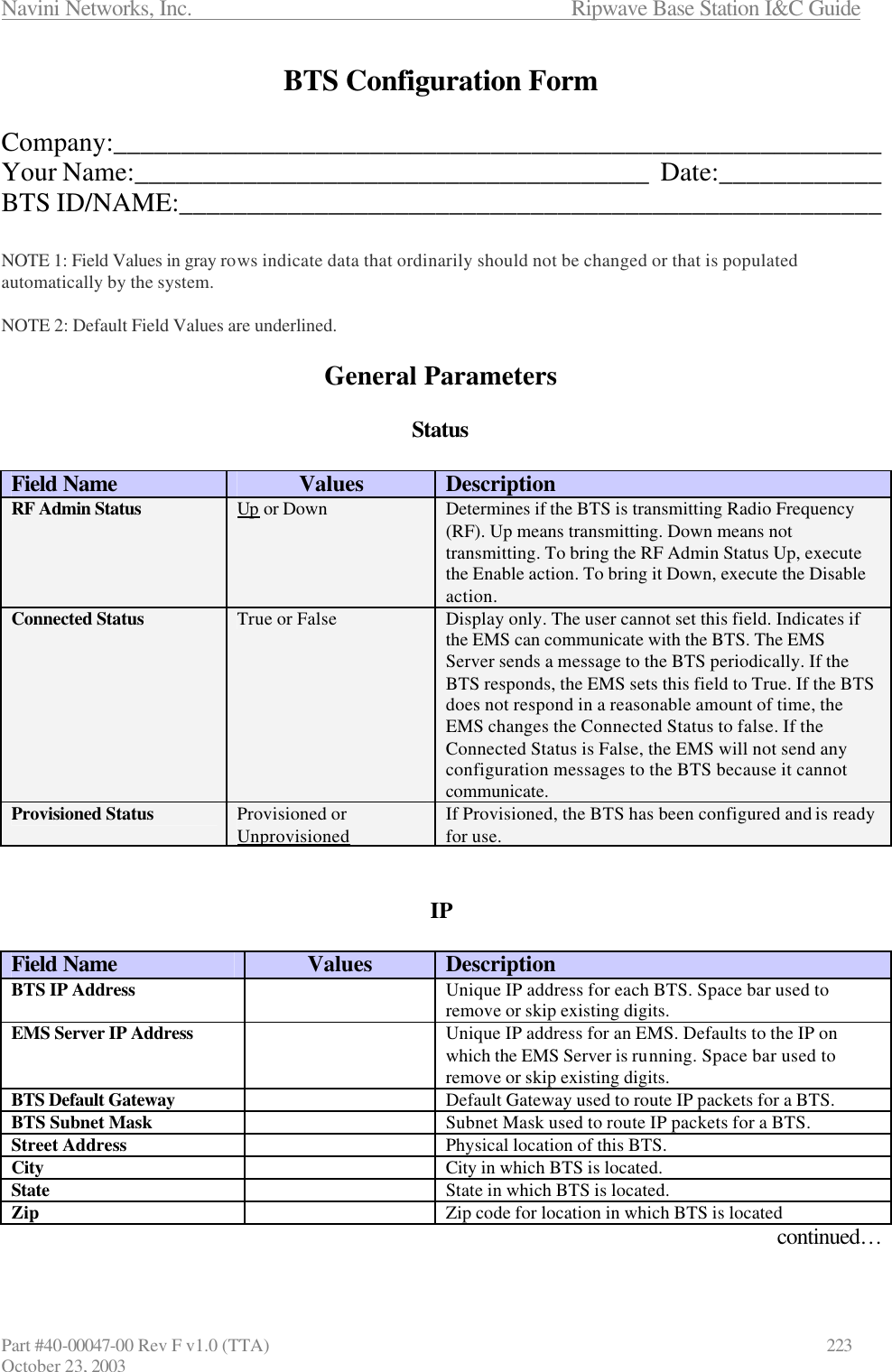
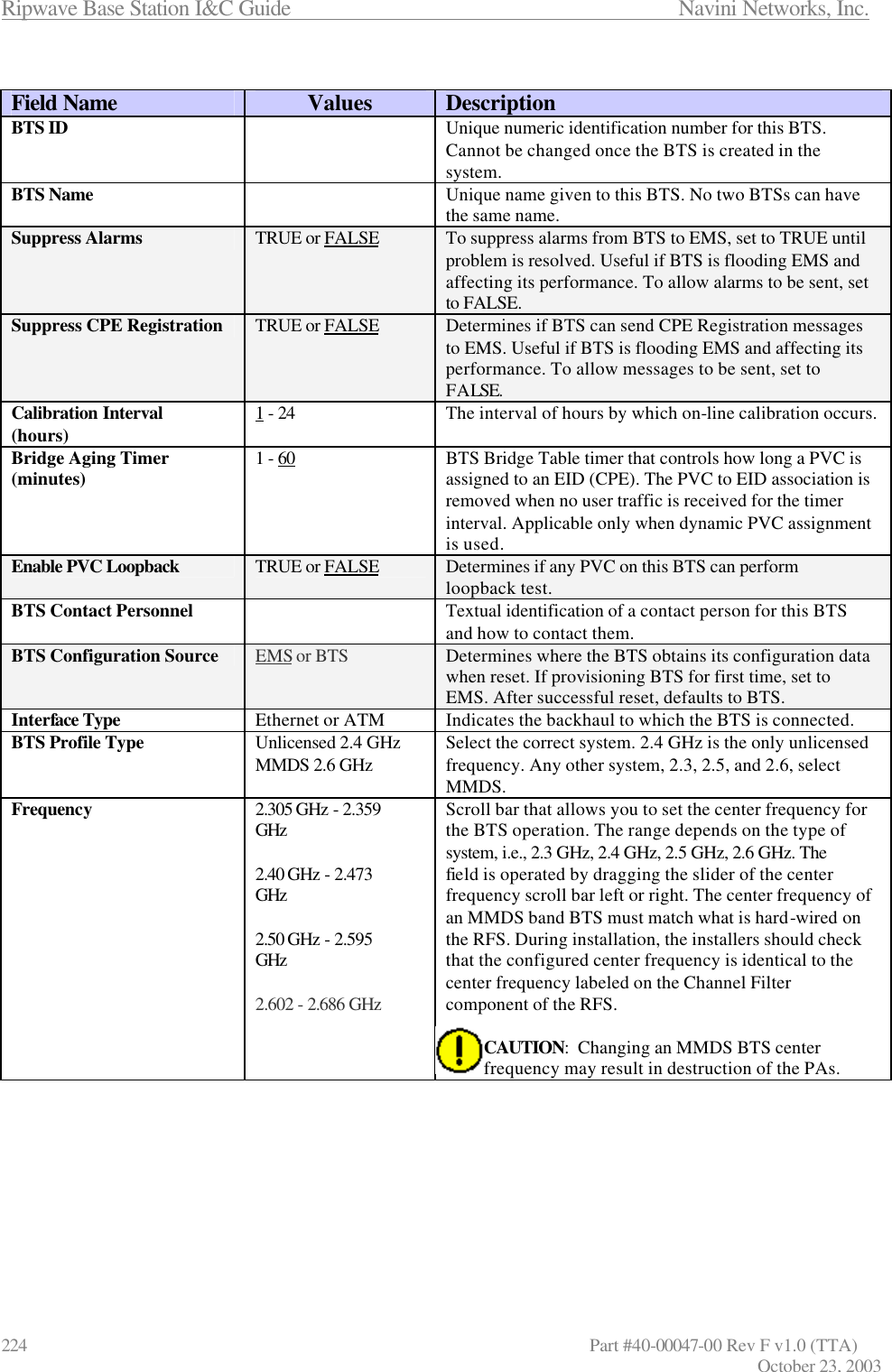
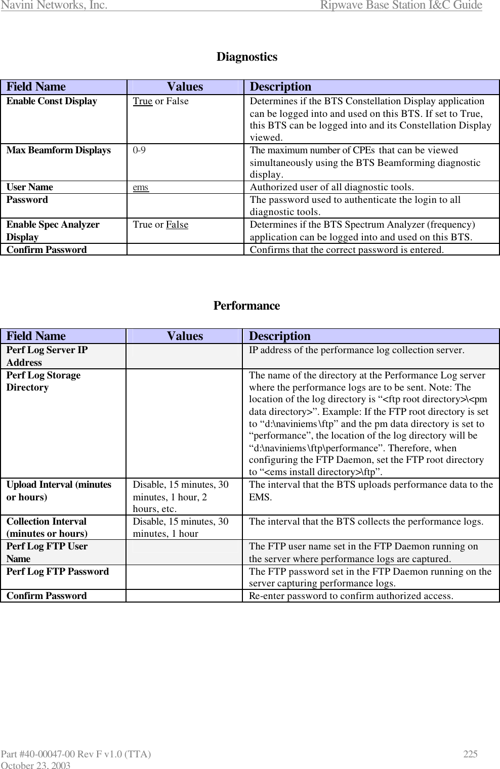
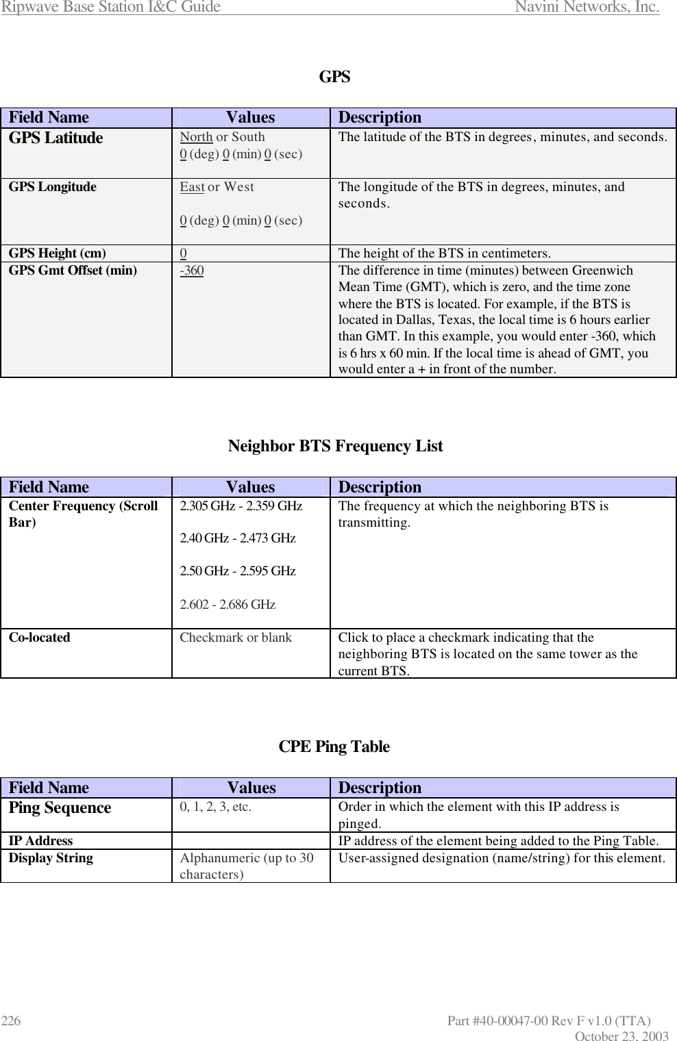
Contents
1.
Manual app 1
2.
Manual app 2
3.
Manual 1
4.
Manual 2
5.
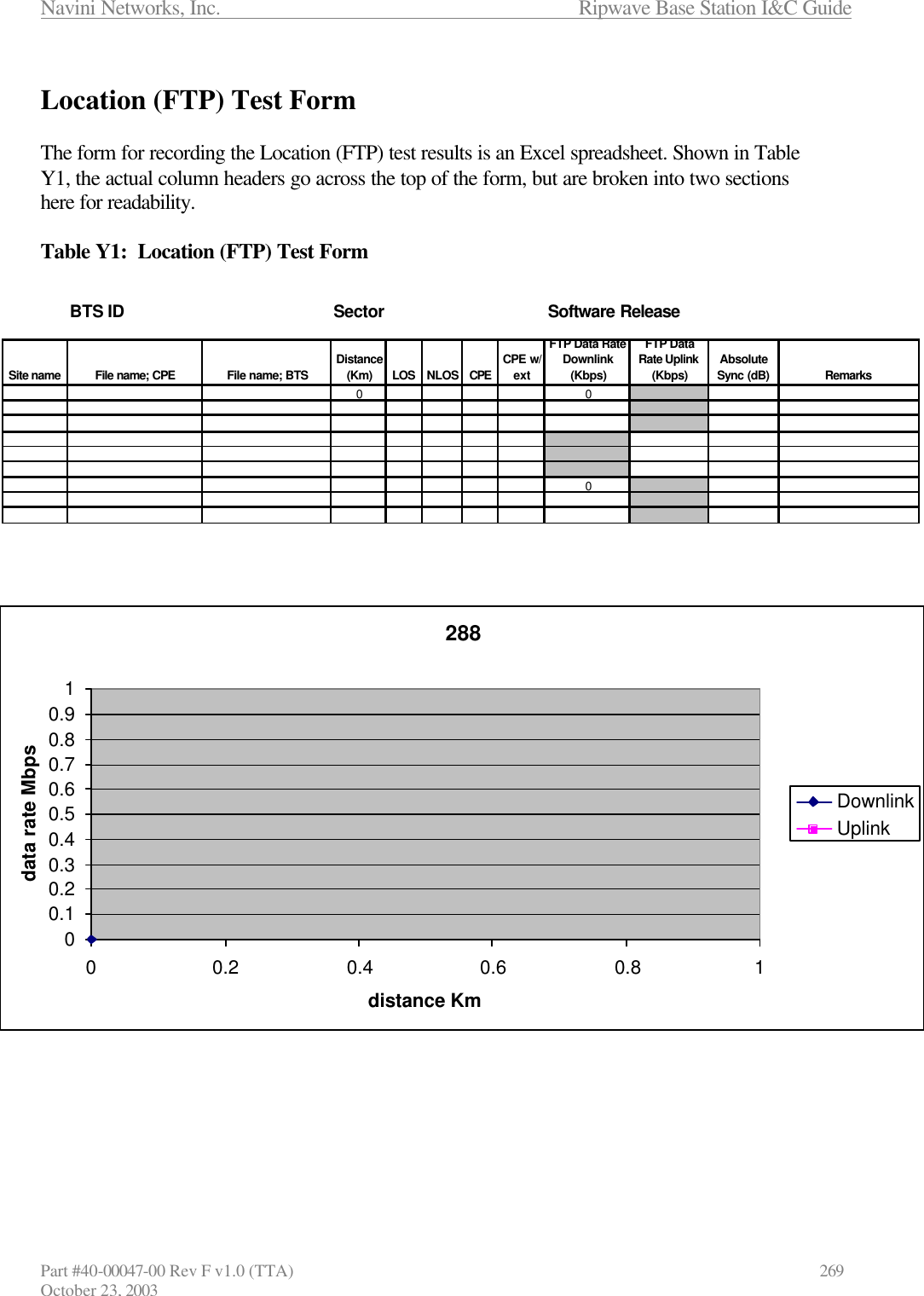
Manual 3
6.
Manual 4
7.
Manaul 5
8.
Manual 6
9.
Manual 7
10.
Guide 1
11.
Guide 2
Manual app 2
Navigation menu
Upload a User Manual
Namespaces
Wiki Guide
HTML
PDF
Info
Views
User Manual
Discussion / Help
Navigation