Cisco Systems 3200 Installation Manual 3200_assembly_guide
3200 to the manual 416af53c-abbe-4a67-9697-d210da2f84bf
2015-01-05
: Cisco-Systems Cisco-Systems-3200-Installation-Manual-203275 cisco-systems-3200-installation-manual-203275 cisco-systems pdf
Open the PDF directly: View PDF ![]() .
.
Page Count: 246 [warning: Documents this large are best viewed by clicking the View PDF Link!]
- Cisco TelePresence System 3200 Assembly Guide Use & Care Guide Field-Replaceable Unit Guide
- Preface
- Overview
- Building the Display Assembly
- Mounting and Leveling the Plasma Displays
- Building the Display Shelf Assembly
- Building the Lighting Assembly
- Building the First Row Table Assembly
- Building the Second Row Table Assembly
- Assembling the Remaining Cisco TelePresence Elements
- Routing Power and Signal Cables
- First-Time Setup
- Use & Care Guide
- Field-Replaceable Unit Guide
- Powering On the System
- Replacing the Camera Cluster-Part Number CTS3K-CAM-CLST-G2
- Replacing a Plasma Display-Part Number CTS-DISP-65-GEN2
- Replacing a Speaker-Part Number CTS-LDSPKR
- Replacing a Codec Unit-Part Number CTS-CODEC-PRI-G2 (Primary Codec) or CTS-CODEC-SEC (Secondary Codec)
- Replacing a Microphone-Part Number CTS-MIC
- Replacing a Light Fixture-Part Number CTS-LIGHT-FIXT
- Replacing the Audio/Video Extension Unit-Part Number CTS-AV-EXP
- Replacing the Auxiliary Control Unit-Part Number CTS-LIGHT-CTRL
- Replacing the Cisco Unified IP Phone-Part Number CP-7975G-CTS
- Replacing the Projector Lamp-Part Number CTS-PRJTR-BL-GEN1
- Replacing the Projector-Part Number CTS-PRJTR-GEN1
- Replacing a PDU-Part Number CTS-PWR-PDU
- Replacing a Display Shelf
- Replacing a First Row Table Top Section
- Replacing a Second Row Table Top Section
- Appendix A: Parts List Sorted by Carton
- Overview
- Carton 1 of 58: Mechanical Accessory Kit, CTS3K-ACC-KIT, 53-2855-xx
- Carton 2 of 58: Mechanical Accessory Kit, 53-2855-xx, CTS3K-ACC2-KIT
- Carton 3 of 58: Primary Codec, CTS-CODEC-PRI-G2, 800-30638-xx
- Carton 4 of 58: Camera Cluster, 800-30872-xx, CTS3K-CAM-CLST-G2
- Carton 5 of 58: Secondary Codec, 800-28202-xx, CTS-CODEC-SEC
- Carton 6 of 58: Secondary Codec, 800-28202-xx, CTS-CODEC-SEC
- Carton 7 of 58: Projector, 74-4824-xx, CTS-PRJTR-GEN1
- Carton 8 of 58: Speaker, 74-4740-xx, CTS-LDSPKR
- Carton 9 of 58: Speaker, 74-4740-xx, CTS-LDSPKR
- Carton 10 of 58: Speaker, 74-4740-xx, CTS-LDSPKR
- Carton 11 of 58: Power Cord, 37-08xx-xx, PWR-CORD10-xx
- Carton 12 of 58: Camera Assembly Bracket, 69-1627-xx, CTS3K-STRUCTURE
- Carton 13 of 58: Brackets, 69-1632-xx, CTS3K-STRUCTURE
- Carton 14 of 58: Privacy Panel, Right Wing, 69-1628-xx, CTS3K-STRUCTURE
- Carton 15 of 58: Front Foot Stabilizer, 69-1624-xx, CST3K-STRUCTURE
- Carton 16 of 58: Front Foot Stabilizer, 69-1624-xx, CST3K-STRUCTURE
- Carton 17 of 58: Front Foot Stabilizer, 69-1624-xx, CST3K-STRUCTURE
- Carton 18 of 58: Display Structure Rear Feet, 69-1625-xx, CTS3K-STRUCTURE
- Carton 19 of 58: Accessory Cabinet Brackets, 69-1630-xx, CTS3K-STRUCTURE
- Carton 20 of 58: Accessory Kit for CTS-3200, 53-3108-xx, CTS32-ACC-KIT
- Carton 22 of 58: Auxiliary Control Unit, CTS-LIGHT-CTRL
- Carton 23 of 58: Plasma Display, 74-4881-xx, CTS-DISP-65-GEN2
- Carton 24 of 58: Plasma Display, 74-4881-xx, CTS-DISP-65-GEN2
- Carton 25 of 58: Plasma Display, 74-4881-xx, CTS-DISP-65-GEN2
- Carton 26 of 58: Second Row Tabletops and Accessory Kit, CTS32-M-2TBL-G2, 69-1853-xx
- Carton 27 of 58: Light Fixture, 74-5361-xx, CTS-LIGHT-FIXT
- Carton 28 of 58: Light Fixture, 74-5361-xx, CTS-LIGHT-FIXT
- Carton 29 of 58: Light Fixture, 74-5361-xx, CTS-LIGHT-FIXT
- Carton 30 of 58: Light Fixture, 74-5362-xx, CTS-LIGHT-FIXT
- Carton 31 of 58: Light Fixture, 74-5362-xx, CTS-LIGHT-FIXT
- Carton 32 of 58: Camera Target, 69-1674-xx, CTS-CAM-TOOL
- Carton 33 of 58: Support Crossbars, 69-1623-01, CTS3K-STRUCTURE
- Carton 34 of 58: Privacy Panels, 69-1629-xx, CTS3K-STRUCTURE
- Carton 35 of 58: Display Structure, 69-1622-xx, CTS3K-STRUCTURE
- Carton 36 of 58: Display Structure, 69-1622-xx, CTS3K-STRUCTURE
- Carton 37 of 58: Display Structure, 69-1622-xx, CTS3K-STRUCTURE
- Carton 38 of 58: Presentation Codec, 69-1887-xx, CTS-HFR-COLLAB-3K
- Carton 39 of 58: Spare Fluorescent Bulbs for Light Fixture, 74-5232-xx, CTS-3000-SPR-BULBS
- Carton 40 of 58: Secondary Codec, 800-28202-xx, CTS-CODEC-SEC
- Carton 41 of 58: Foam Bumpers, 69-1634-xx, CTS3K-STRUCTURE
- Carton 42 of 58: Foam Bumpers, 69-1634-xx, CTS3K-STRUCTURE
- Carton 43 of 58: Foam Bumpers, 69-1634-xx, CTS3K-STRUCTURE
- Carton 44 of 58: Lighting Assembly, 69-1613-xx, CTS3K-LIGHT-STR
- Carton 45 of 58: Projector Bracket, 69-1631-xx, CTS3K-STRUCTURE
- Carton 46 of 58: Projector Screen, 74-5416-xx, CTS3K-SCREEN
- Carton 47 of 58: Accessory Cabinet, Right, 69-1837-xx, CTS3K-M-TABLE-G2
- Carton 48 of 58: Accessory Cabinet, Left, 69-1838-xx, CTS3K-M-TABLE-G2
- Carton 49 of 58: Lighting Assembly, 69-1612-xx, CTS3K-LIGHT-STR
- Carton 50 of 58: Cisco TelePresence 3200 Structure-Addition to Standard CTS-3000, CTS32-STRUCTURE, 69-1854-01
- Carton 51 of 58: Display Shelf Supports and Codec Tray, 69-1626-xx, CTS3K-STRUCTURE
- Carton 52 of 58: Tabletop Leg Base, 69-1620-xx, CTS3K-STRUCTURE
- Carton 53 of 58: Tabletop Leg Base, 69-1914-xx, CTS3K-STRUCTURE
- Carton 54 of 58: Tabletop Leg Base, 69-1915-xx, CTS3K-STRUCTURE
- Carton 55 of 58: Lighting Assembly, 69-1613-xx, CTS3K-LIGHT-STR
- Carton 56 of 58: Projector Bracket, 69-1631-xx, CTS3K-STRUCTURE
- Carton 57 of 58: Foam Bumpers, 69-1634-xx, CTS3K-STRUCTURE
- Carton 58 of 58: Tabletop Sections, Display Shelves, and Speaker Boards, 69-1835-xx, CTS3K-M
- Appendix B: Region- and Country-Specific Equipment

THE SPECIFICATIONS AND INFORMATION REGARDING THE PRODUCTS IN THIS MANUAL ARE SUBJECT TO CHANGE WITHOUT NOTICE. ALL
STATEMENTS, INFORMATION, AND RECOMMENDATIONS IN THIS MANUAL ARE BELIEVED TO BE ACCURATE BUT ARE PRESENTED WITHOUT
WARRANTY OF ANY KIND, EXPRESS OR IMPLIED. USERS MUST TAKE FULL RESPONSIBILITY FOR THEIR APPLICATION OF ANY PRODUCTS.
THE SOFTWARE LICENSE AND LIMITED WARRANTY FOR THE ACCOMPANYING PRODUCT ARE SET FORTH IN THE INFORMATION PACKET THAT
SHIPPED WITH THE PRODUCT AND ARE INCORPORATED HEREIN BY THIS REFERENCE. IF YOU ARE UNABLE TO LOCATE THE SOFTWARE LICENSE
OR LIMITED WARRANTY, CONTACT YOUR CISCO REPRESENTATIVE FOR A COPY.
The following information is for FCC compliance of Class A devices: This equipment has been tested and found to comply with the limits for a Class A digital device, pursuant
to part 15 of the FCC rules. These limits are designed to provide reasonable protection against harmful interference when the equipment is operated in a commercial
environment. This equipment generates, uses, and can radiate radio-frequency energy and, if not installed and used in accordance with the instruction manual, may cause
harmful interference to radio communications. Operation of this equipment in a residential area is likely to cause harmful interference, in which case users will be required
to correct the interference at their own expense.
The following information is for FCC compliance of Class B devices: This equipment has been tested and found to comply with the limits for a Class B digital device, pursuant
to part 15 of the FCC rules. These limits are designed to provide reasonable protection against harmful interference in a residential installation. This equipment generates,
uses and can radiate radio frequency energy and, if not installed and used in accordance with the instructions, may cause harmful interference to radio communications.
However, there is no guarantee that interference will not occur in a particular installation. If the equipment causes interference to radio or television reception, which can be
determined by turning the equipment off and on, users are encouraged to try to correct the interference by using one or more of the following measures:
• Reorient or relocate the receiving antenna.
• Increase the separation between the equipment and receiver.
• Connect the equipment into an outlet on a circuit different from that to which the receiver is connected.
• Consult the dealer or an experienced radio/TV technician for help.
Modifications to this product not authorized by Cisco could void the FCC approval and negate your authority to operate the product.
The Cisco implementation of TCP header compression is an adaptation of a program developed by the University of California, Berkeley (UCB) as part of UCB’s public
domain version of the UNIX operating system. All rights reserved. Copyright © 1981, Regents of the University of California.
NOTWITHSTANDING ANY OTHER WARRANTY HEREIN, ALL DOCUMENT FILES AND SOFTWARE OF THESE SUPPLIERS ARE PROVIDED “AS IS” WITH
ALL FAULTS. CISCO AND THE ABOVE-NAMED SUPPLIERS DISCLAIM ALL WARRANTIES, EXPRESSED OR IMPLIED, INCLUDING, WITHOUT
LIMITATION, THOSE OF MERCHANTABILITY, FITNESS FOR A PARTICULAR PURPOSE AND NONINFRINGEMENT OR ARISING FROM A COURSE OF
DEALING, USAGE, OR TRADE PRACTICE.
IN NO EVENT SHALL CISCO OR ITS SUPPLIERS BE LIABLE FOR ANY INDIRECT, SPECIAL, CONSEQUENTIAL, OR INCIDENTAL DAMAGES, INCLUDING,
WITHOUT LIMITATION, LOST PROFITS OR LOSS OR DAMAGE TO DATA ARISING OUT OF THE USE OR INABILITY TO USE THIS MANUAL, EVEN IF CISCO
OR ITS SUPPLIERS HAVE BEEN ADVISED OF THE POSSIBILITY OF SUCH DAMAGES.
CCDE, CCENT, Cisco Eos, Cisco HealthPresence, the Cisco logo, Cisco Lumin, Cisco Nexus, Cisco StadiumVision, Cisco TelePresence, Cisco WebEx, DCE, and Welcome
to the Human Network are trademarks; Changing the Way We Work, Live, Play, and Learn and Cisco Store are service marks; and Access Registrar, Aironet, AsyncOS,
Bringing the Meeting To You, Catalyst, CCDA, CCDP, CCIE, CCIP, CCNA, CCNP, CCSP, CCVP, Cisco, the Cisco Certified Internetwork Expert logo, Cisco IOS,
Cisco Press, Cisco Systems, Cisco Systems Capital, the Cisco Systems logo, Cisco Unity, Collaboration Without Limitation, EtherFast, EtherSwitch, Event Center, Fast Step,
Follow Me Browsing, FormShare, GigaDrive, HomeLink, Internet Quotient, IOS, iPhone, iQuick Study, IronPort, the IronPort logo, LightStream, Linksys, MediaTone,
MeetingPlace, MeetingPlace Chime Sound, MGX, Networkers, Networking Academy, Network Registrar, PCNow, PIX, PowerPanels, ProConnect, ScriptShare, SenderBase,
SMARTnet, Spectrum Expert, StackWise, The Fastest Way to Increase Your Internet Quotient, TransPath, WebEx, and the WebEx logo are registered trademarks of
Cisco Systems, Inc. and/or its affiliates in the United States and certain other countries.
All other trademarks mentioned in this document or website are the property of their respective owners. The use of the word partner does not imply a partnership relationship
between Cisco and any other company. (0812R)
Any Internet Protocol (IP) addresses used in this document are not intended to be actual addresses. Any examples, command display output, and figures included in the
document are shown for illustrative purposes only. Any use of actual IP addresses in illustrative content is unintentional and coincidental.
Cisco TelePresence System 3200
Assembly Guide
Use & Care Guide
Field-Replaceable Unit Guide
© 2008 Cisco Systems, Inc. All rights reserved.

Contents
iii
Cisco TelePresence System 3200
OL-14521-01
Preface ix
Introduction i-ix
Conventions i-ix
Obtaining Documentation, Obtaining Support, and Security Guidelines i-x
Related Documentation i-x
CHAPTER
1Overview 1-1
Chapter Organization 1-1
Conventions and Terminology 1-3
Tools and Equipment List 1-3
CHAPTER
2Building the Display Assembly 2-1
Parts List 2-1
CHAPTER
3Mounting and Leveling the Plasma Displays 3-1
Parts List 3-1
Purpose of Leveling the Plasma displays 3-4
Leveling Alignment Points 3-4
Leveling Goals 3-5
CHAPTER
5Building the Display Shelf Assembly 5-1
Parts List 5-1
CHAPTER
4Building the Lighting Assembly 4-1
Parts List 4-1
CHAPTER
6Building the First Row Table Assembly 6-1
Parts List 6-1
CHAPTER
7Building the Second Row Table Assembly 7-1
Parts List 7-1
CHAPTER
8Assembling the Remaining Cisco TelePresence Elements 8-1
Parts List 8-1
CHAPTER
9Routing Power and Signal Cables 9-1
Parts List 9-1

Contents
iv
Cisco TelePresence System 3200
OL-14521-01
CHAPTER
10 First-Time Setup 10-1
Parts List 10-1
Loading CTS Administration Software 10-1
Configuring an Alternate TFTP Server (Optional) 10-4
Setting Up CTS Components 10-4
Setting Up the Displays 10-5
Setting Up the Cameras 10-6
Setting Up the Speakers 10-13
Setting Up the Microphones 10-13
Setting Up the Projector 10-14
Troubleshooting Presentation Devices 10-16
Other Devices 10-18
CHAPTER
11 Use & Care Guide 11-1
Maintaining the Tabletop 11-1
Cleaning the Plasma displays 11-1
Cleaning the Camera lens 11-2
Maintaining the Projector 11-2
CHAPTER
12 Field-Replaceable Unit Guide 12-1
Powering On the System 12-1
Replacing the Camera Cluster—Part Number CTS3K-CAM-CLST-G2 12-2
Required Information, Tools, and Equipment 12-2
Removing and Replacing the Camera Cluster 12-3
Replacing a Plasma Display—Part Number CTS-DISP-65-GEN2 12-4
Required Information, Tools, and Equipment 12-4
Removing Audio Components 12-5
Removing the Camera Cluster 12-6
Removing the Left Door 12-6
Removing a Display Shelf 12-6
Removing the Display Screen and Completing the Procedure 12-7
Replacing a Speaker—Part Number CTS-LDSPKR 12-8
Required Information, Tools, and Equipment 12-8
Removing and Replacing a Speaker 12-8
Replacing a Codec Unit—Part Number CTS-CODEC-PRI-G2 (Primary Codec) or CTS-CODEC-SEC
(Secondary Codec) 12-10
Required Information, Tools, and Equipment 12-10
Removing and Replacing a Codec 12-10

Contents
v
Cisco TelePresence System 3200
OL-14521-01
Replacing a Microphone—Part Number CTS-MIC 12-12
Required Information, Tools, and Equipment 12-12
Removing and Replacing a First Row Microphone 12-12
Removing and Replacing a Second Row Microphone 12-13
Replacing a Light Fixture—Part Number CTS-LIGHT-FIXT 12-14
Required Information, Tools, and Equipment 12-14
Replacement Bulbs 12-14
Replacing a Light Fixture 12-15
Replacing the Audio/Video Extension Unit—Part Number CTS-AV-EXP 12-15
Replacing the Auxiliary Control Unit—Part Number CTS-LIGHT-CTRL 12-16
Replacing the Cisco Unified IP Phone—Part Number CP-7975G-CTS 12-17
Replacing the Projector Lamp—Part Number CTS-PRJTR-BL-GEN1 12-17
Replacing the Projector—Part Number CTS-PRJTR-GEN1 12-18
Replacing a PDU—Part Number CTS-PWR-PDU 12-19
Replacing a Display Shelf 12-20
Required Information, Tools, and Equipment 12-20
Removing and Replacing a Display Shelf Row Table Section 12-20
Replacing a First Row Table Top Section 12-22
Required Information, Tools, and Equipment 12-22
Removing and Replacing a First Row Table Top Section 12-22
Replacing a Second Row Table Top Section 12-24
Required Information, Tools, and Equipment 12-24
Removing and Replacing a Second Row Table Top Section 12-24
Appendix A: Parts List Sorted by Carton A-1
Overview A-1
Carton 1 of 58: Mechanical Accessory Kit, CTS3K-ACC-KIT, 53-2855-xx A-1
Carton 2 of 58: Mechanical Accessory Kit, 53-2855-xx, CTS3K-ACC2-KIT A-3
Carton 3 of 58: Primary Codec, CTS-CODEC-PRI-G2, 800-30638-xx A-3
Carton 4 of 58: Camera Cluster, 800-30872-xx, CTS3K-CAM-CLST-G2 A-4
Carton 5 of 58: Secondary Codec, 800-28202-xx, CTS-CODEC-SEC A-4
Carton 6 of 58: Secondary Codec, 800-28202-xx, CTS-CODEC-SEC A-4
Carton 7 of 58: Projector, 74-4824-xx, CTS-PRJTR-GEN1 A-4
Carton 8 of 58: Speaker, 74-4740-xx, CTS-LDSPKR A-5
Carton 9 of 58: Speaker, 74-4740-xx, CTS-LDSPKR A-5
Carton 10 of 58: Speaker, 74-4740-xx, CTS-LDSPKR A-5
Carton 11 of 58: Power Cord, 37-08xx-xx, PWR-CORD10-xx A-5

Contents
vi
Cisco TelePresence System 3200
OL-14521-01
Carton 12 of 58: Camera Assembly Bracket, 69-1627-xx, CTS3K-STRUCTURE A-6
Carton 13 of 58: Brackets, 69-1632-xx, CTS3K-STRUCTURE A-6
Carton 14 of 58: Privacy Panel, Right Wing, 69-1628-xx, CTS3K-STRUCTURE A-6
Carton 15 of 58: Front Foot Stabilizer, 69-1624-xx, CST3K-STRUCTURE A-6
Carton 16 of 58: Front Foot Stabilizer, 69-1624-xx, CST3K-STRUCTURE A-7
Carton 17 of 58: Front Foot Stabilizer, 69-1624-xx, CST3K-STRUCTURE A-7
Carton 18 of 58: Display Structure Rear Feet, 69-1625-xx, CTS3K-STRUCTURE A-7
Carton 19 of 58: Accessory Cabinet Brackets, 69-1630-xx, CTS3K-STRUCTURE A-7
Carton 20 of 58: Accessory Kit for CTS-3200, 53-3108-xx, CTS32-ACC-KIT A-8
Carton 22 of 58: Auxiliary Control Unit, CTS-LIGHT-CTRL A-8
Carton 23 of 58: Plasma Display, 74-4881-xx, CTS-DISP-65-GEN2 A-8
Carton 24 of 58: Plasma Display, 74-4881-xx, CTS-DISP-65-GEN2 A-9
Carton 25 of 58: Plasma Display, 74-4881-xx, CTS-DISP-65-GEN2 A-9
Carton 26 of 58: Second Row Tabletops and Accessory Kit, CTS32-M-2TBL-G2, 69-1853-xx A-9
Carton 27 of 58: Light Fixture, 74-5361-xx, CTS-LIGHT-FIXT A-10
Carton 28 of 58: Light Fixture, 74-5361-xx, CTS-LIGHT-FIXT A-10
Carton 29 of 58: Light Fixture, 74-5361-xx, CTS-LIGHT-FIXT A-10
Carton 30 of 58: Light Fixture, 74-5362-xx, CTS-LIGHT-FIXT A-11
Carton 31 of 58: Light Fixture, 74-5362-xx, CTS-LIGHT-FIXT A-11
Carton 32 of 58: Camera Target, 69-1674-xx, CTS-CAM-TOOL A-11
Carton 33 of 58: Support Crossbars, 69-1623-01, CTS3K-STRUCTURE A-12
Carton 34 of 58: Privacy Panels, 69-1629-xx, CTS3K-STRUCTURE A-12
Carton 35 of 58: Display Structure, 69-1622-xx, CTS3K-STRUCTURE A-12
Carton 36 of 58: Display Structure, 69-1622-xx, CTS3K-STRUCTURE A-12
Carton 37 of 58: Display Structure, 69-1622-xx, CTS3K-STRUCTURE A-13
Carton 38 of 58: Presentation Codec, 69-1887-xx, CTS-HFR-COLLAB-3K A-13
Carton 39 of 58: Spare Fluorescent Bulbs for Light Fixture, 74-5232-xx, CTS-3000-SPR-BULBS A-13
Carton 40 of 58: Secondary Codec, 800-28202-xx, CTS-CODEC-SEC A-14
Carton 41 of 58: Foam Bumpers, 69-1634-xx, CTS3K-STRUCTURE A-14
Carton 42 of 58: Foam Bumpers, 69-1634-xx, CTS3K-STRUCTURE A-14
Carton 43 of 58: Foam Bumpers, 69-1634-xx, CTS3K-STRUCTURE A-14
Carton 44 of 58: Lighting Assembly, 69-1613-xx, CTS3K-LIGHT-STR A-15
Carton 45 of 58: Projector Bracket, 69-1631-xx, CTS3K-STRUCTURE A-15
Carton 46 of 58: Projector Screen, 74-5416-xx, CTS3K-SCREEN A-15
Carton 47 of 58: Accessory Cabinet, Right, 69-1837-xx, CTS3K-M-TABLE-G2 A-15

Contents
vii
Cisco TelePresence System 3200
OL-14521-01
Carton 48 of 58: Accessory Cabinet, Left, 69-1838-xx, CTS3K-M-TABLE-G2 A-16
Carton 49 of 58: Lighting Assembly, 69-1612-xx, CTS3K-LIGHT-STR A-16
Carton 50 of 58: Cisco TelePresence 3200 Structure—Addition to Standard CTS-3000,
CTS32-STRUCTURE, 69-1854-01 A-17
Carton 51 of 58: Display Shelf Supports and Codec Tray, 69-1626-xx, CTS3K-STRUCTURE A-18
Carton 52 of 58: Tabletop Leg Base, 69-1620-xx, CTS3K-STRUCTURE A-18
Carton 53 of 58: Tabletop Leg Base, 69-1914-xx, CTS3K-STRUCTURE A-18
Carton 54 of 58: Tabletop Leg Base, 69-1915-xx, CTS3K-STRUCTURE A-19
Carton 55 of 58: Lighting Assembly, 69-1613-xx, CTS3K-LIGHT-STR A-19
Carton 56 of 58: Projector Bracket, 69-1631-xx, CTS3K-STRUCTURE A-19
Carton 57 of 58: Foam Bumpers, 69-1634-xx, CTS3K-STRUCTURE A-19
Carton 58 of 58: Tabletop Sections, Display Shelves, and Speaker Boards, 69-1835-xx, CTS3K-M A-20
Appendix B: Region- and Country-Specific Equipment B-1
Asia Pacific B-1
Argentina B-1
Australia B-2
Central Europe B-2
China B-2
Europe B-2
India, UAE, South Africa B-3
Israel B-3
Italy B-3
Japan B-3
North America B-4
Switzerland B-4
United Kingdom B-4

Contents
viii
Cisco TelePresence System 3200
OL-14521-01

ix
Cisco TelePresence System 3200
OL-14521-01
Preface
Revised: July 28, 2008, OL-14521-01
Introduction
The Cisco TelePresence 3200 Assembly Guide outlines the steps and best practices for assembling and
installing the Cisco TelePresence 3200.
This guide is intended primarily for installers of the Cisco TelePresence System 3200. Site planners,
network administrators, and facility maintenance personnel may also find this document useful.
This preface provides the following information for using this guide and for accessing other resources.
• Conventions, page ix
• Obtaining Documentation, Obtaining Support, and Security Guidelines, page x
• Related Documentation, page x
Conventions
This document uses the following conventions to convey information and alert the user to conditions
requiring special awareness.
Warning
This warning symbol means danger. You are in a situation that could cause bodily injury. Before you
work on any equipment, you must be aware of the hazards involved with electrical circuitry and
familiar with standard practices for preventing accidents.
Caution Means reader be careful. In this situation, you might do something that could result in equipment
damage or loss of data.
Note Means reader take note. Notes contain helpful suggestions or references to material not covered in the
publication.

x
Cisco TelePresence System 3200
OL-14521-01
Preface
Obtaining Documentation, Obtaining Support, and Security Guidelines
Tip Means the information contains useful tips.
Obtaining Documentation, Obtaining Support, and Security
Guidelines
For information on obtaining documentation, submitting a service request, and gathering additional
information, see the monthly What’s New in Cisco Product Documentation, which also lists all new and
revised Cisco technical documentation, at:
http://www.cisco.com/en/US/docs/general/whatsnew/whatsnew.html
Subscribe to the What’s New in Cisco Product Documentation as a Really Simple Syndication (RSS) feed
and set content to be delivered directly to your desktop using a reader application. The RSS feeds are a free
service and Cisco currently supports RSS version 2.0.
Related Documentation
The Cisco TelePresence system documentation set includes a variety of online and printed guides
designed to aid the assemblers, installers, system administrators, and users in the setup, configuration,
administration, and use of the Cisco TelePresence. These documents include:
• Cisco TelePresence Hardware Options and Upgrade Guide, OL-16441-01
• Cisco TelePresence System 1000 Assembly, Use & Care, and Field Replacement Unit Guide,
OL-16247-01. There is also a pointer document for this guide, 78-17800-02.
• Cisco TelePresence System 3000 Assembly, Use & Care, and Field Replacement Unit Guide,
OL-16246-01. There is also a pointer document for this guide, 78-17795-02.
• Cisco TelePresence and Cisco Unified Communications Manager Installation and Configuration
Guide, OL-11326-02
• Cisco TelePresence System Release 1.4 Administrator’s Guide, OL-13676-03
• Release Notes for Cisco TelePresence System, Release 1.4, OL-12074-05
• Cisco TelePresence Meeting User’s Guide, 78-17791-01
• Cisco TelePresence System Release 1.4 Meeting Quick Reference, 78-17792-02
• Cisco TelePresence Manager Release 1.3 Administration and Installation Guide, OL-13673-02
• Cisco TelePresence Manager Release Notes, OL-11298-01
All of these documents are available at the Cisco documentation website.

CHAPTER
1-1
Cisco TelePresence System 3200
OL-14521-01
1
Overview
Revised: July 28, 2008, OL-14521-01
Chapter Organization
Chapter 1, “Overview” (this chapter)
• Provides chapter organization and content of this document and an overview of the steps you
perform to install a CTS-3200 system.
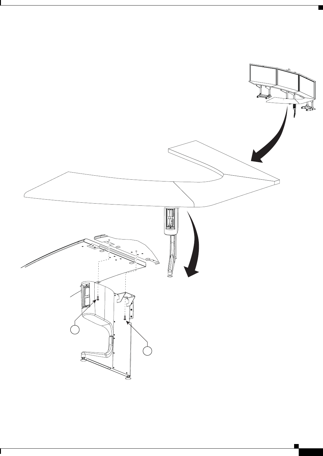
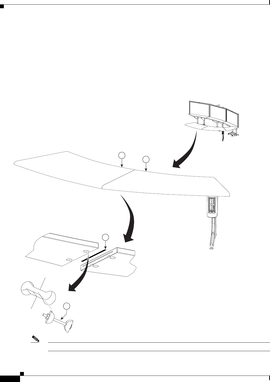
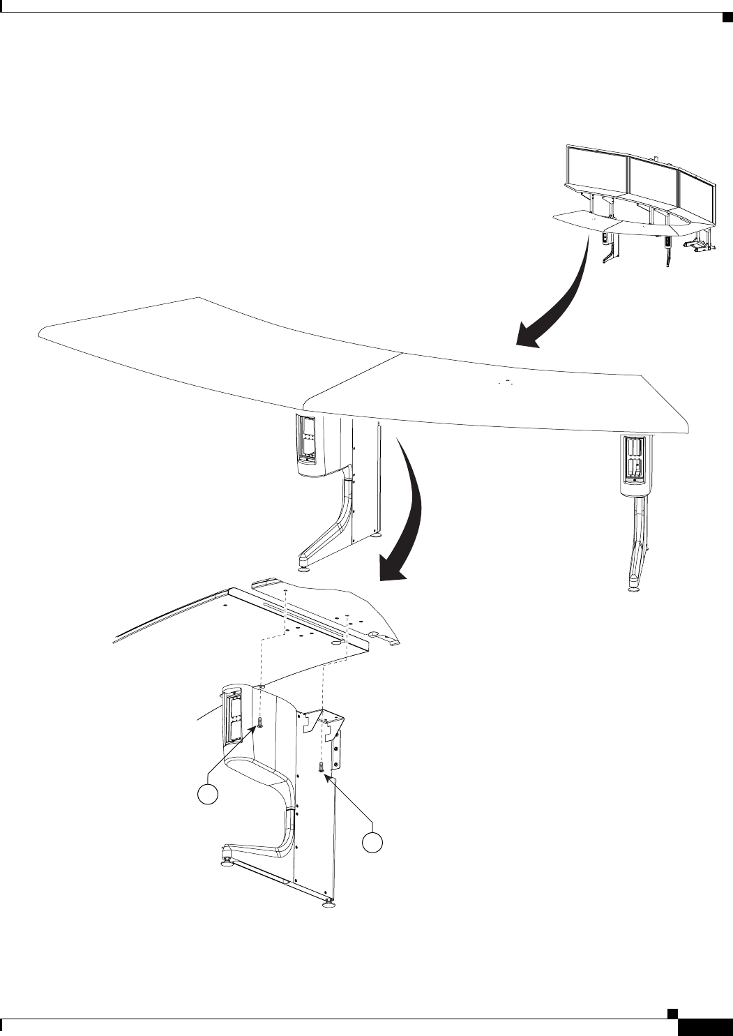
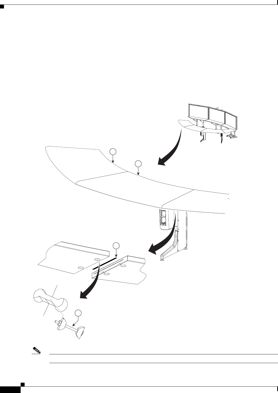
Chapter 2, “Building the Display Assembly”
• The steps for assembling the three Display structures, connecting them, and positioning them in the
conference room are described in a series of illustrations.
• Each illustration builds upon the previous illustration to describe the complete process of building
the Display assembly.
• Each illustration is keyed numerically to the Chapter Parts List, appearing at the beginning of the
chapter. You can refer to the Parts List to identify the specific fastener or bracket being used in an
illustration.
• Additional information may appear below each illustration.
Chapter 3, “Mounting and Leveling the Plasma Displays”
• This chapter uses illustrations to describe the leveling alignment points and the processes used to
level the plasma displays. This chapter is organized the same as Chapter 2.
Chapter 4, “Building the Lighting Assembly”
• This chapter describes the procedures used to build the lighting assembly and is organized the same
as Chapter 2.
Chapter 5, “Building the Display Shelf Assembly”
• This chapter describes how to build the display shelf assembly and is organized the same as Chapter
2.
Chapter 6, “Building the First Row Table Assembly”
• This chapter describes the procedure to build the first row table and is organized the same as Chapter
2.

1-2
Cisco TelePresence System 3200
OL-14521-01
Chapter 1 Overview
Chapter Organization
Chapter 7, “Building the Second Row Table Assembly”
• This chapter describes how to build the second row table and is organized the same as Chapter 2.
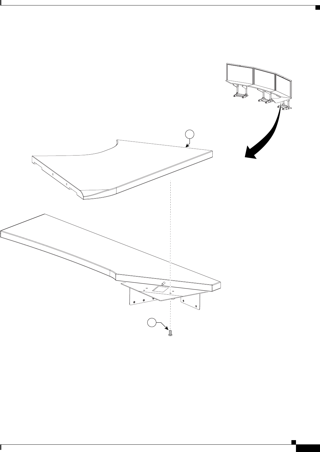
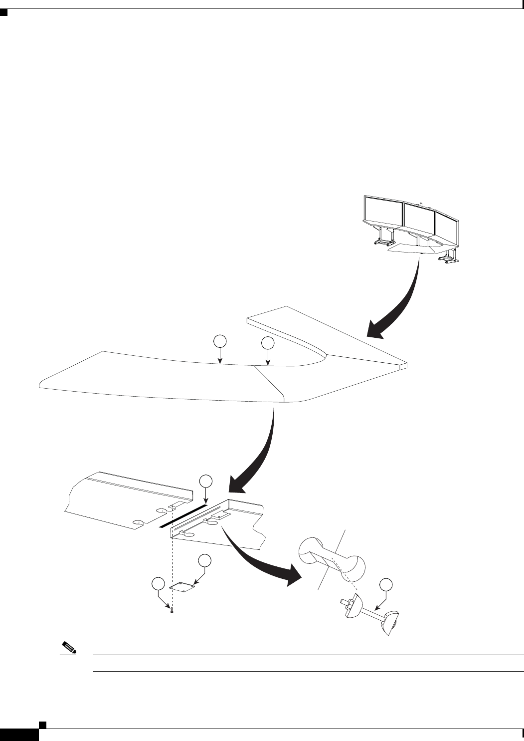
Chapter 8, “Assembling the Remaining Cisco TelePresence Elements”
• This chapter is organized the same as Chapter 2.
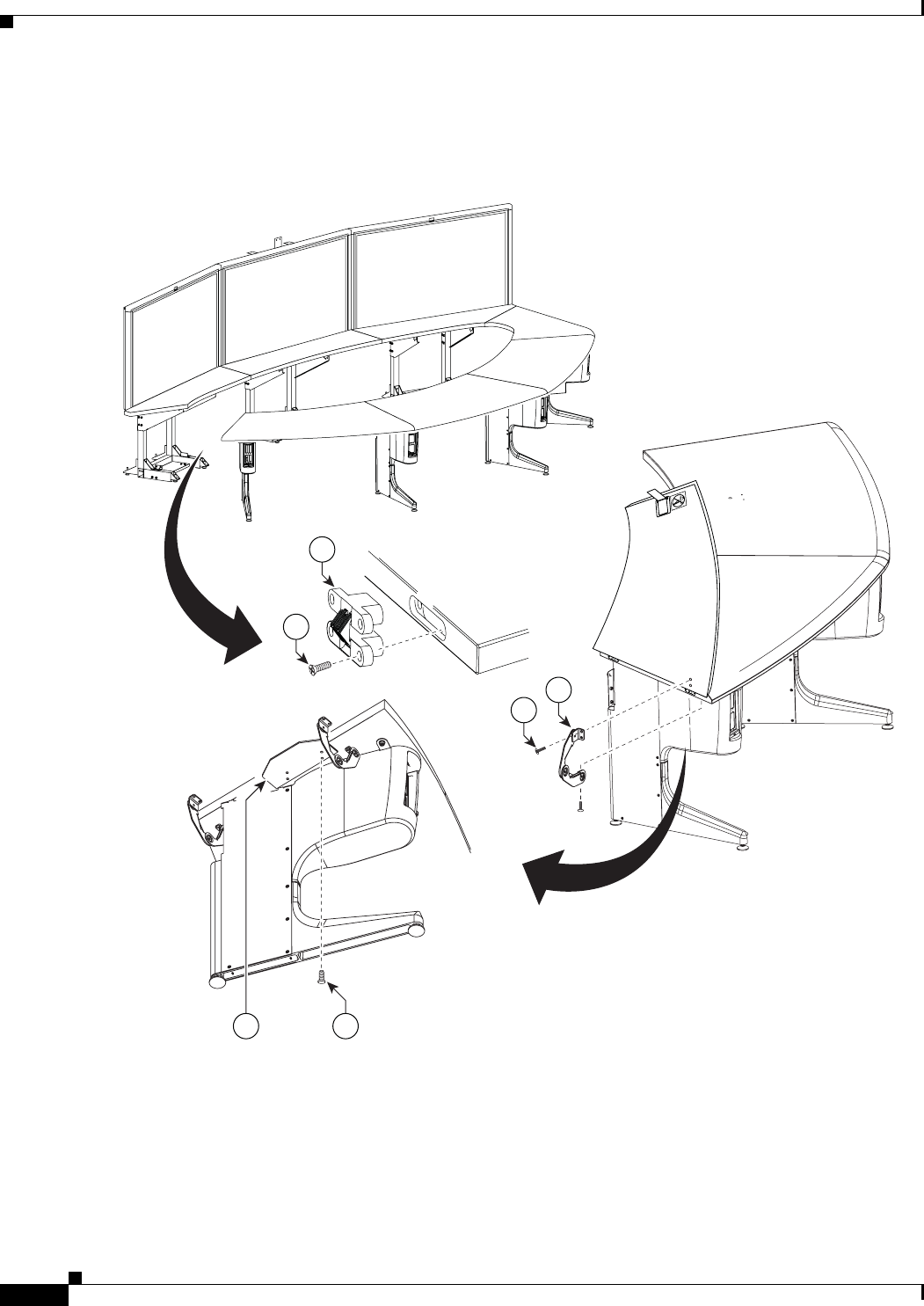
• Each element is described using one or more illustrations. The elements are:
–
Camera assembly—attaches to the center Display structure
–
Front row table leg wiring assembly—wired for power and network connectivity
–
Projector assembly—attaches to the underside of the center table segment
–
Codec and Audio/Video Expansion Unit assembly—attach the codecs to each Display
structure and attach the extension unit to the center display structure
–
Speaker assembly—attach to the underside of the Display shelf
–
Projector Screen assembly—attaches to the underside of the Display shelf
–
Cisco Unified IP Phone 7975—used for initial configuration of the Cisco TelePresence system
and to join meetings
–
Camera Target assembly—used for camera focus and alignment
Chapter 9, “Routing Power and Signal Cables”
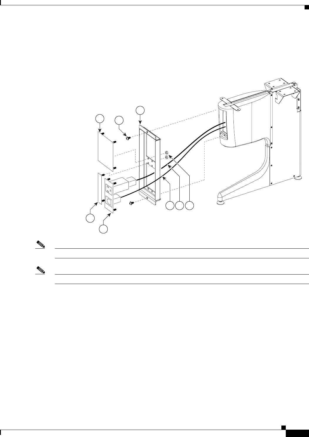
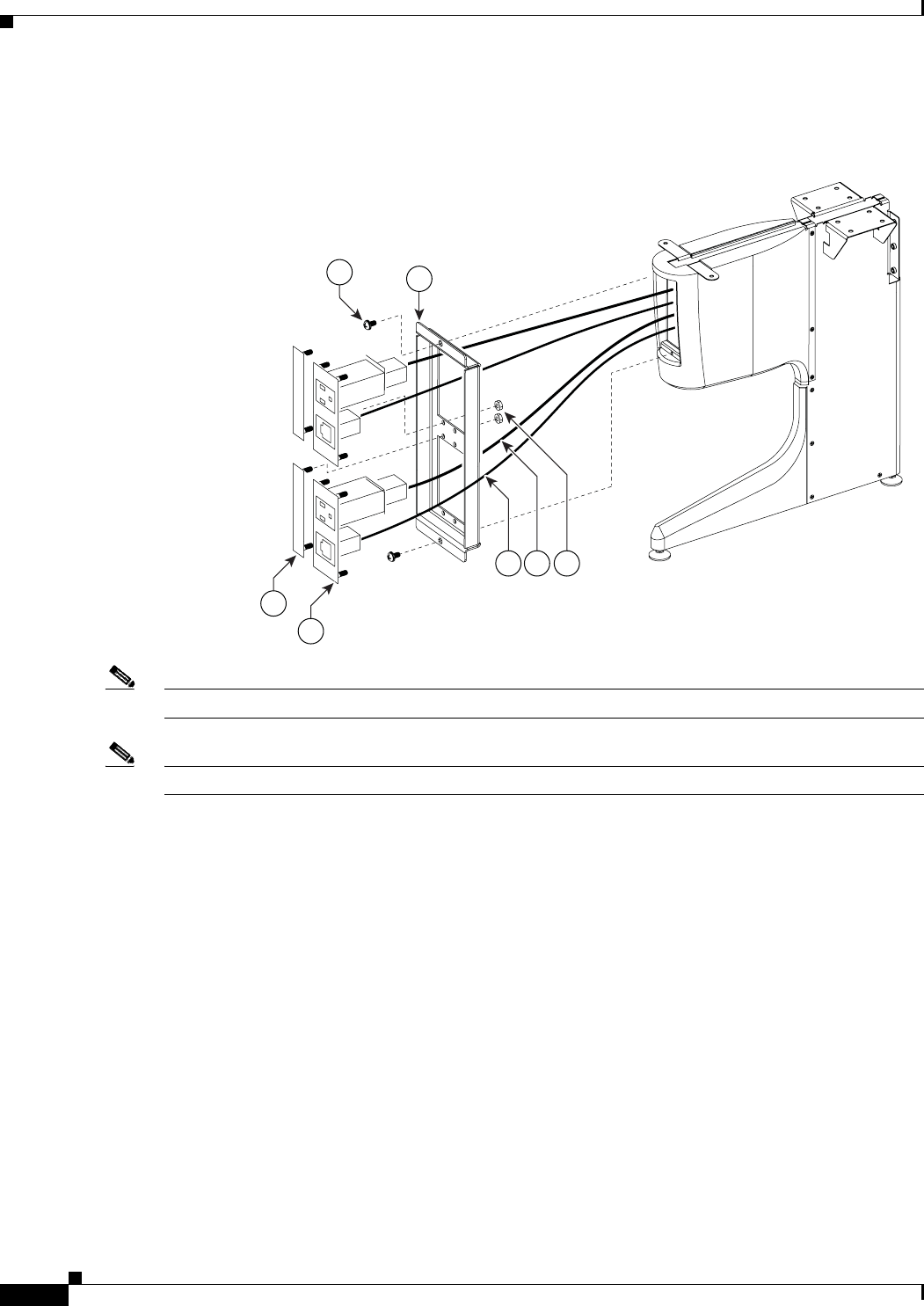
• A series of illustrations are used to describe the routing and connection of power and signal cables
for the front row and the display assembly area.
• Illustrations show you the routing path to take for all cables.
• Illustrations showing cables terminating in a Codec include a close-up of the Codec.
Chapter 10, “First-Time Setup”
• This chapter describes the configuration you perform to set up your Cisco TelePresence System
3200 for the first time.
Chapter 11, “Use & Care Guide”
• This chapter provides information on maintaining several elements of the
Cisco TelePresence System 3200, including the tabletop and plasma displays.
Chapter 12, “Field-Replaceable Unit Guide”
• This chapter describes removal and replacement processes for various elements of the
Cisco TelePresence System 3200.
Appendix A: Parts List Sorted by Carton
• This appendix lists all parts included in the individual chapter parts lists, and sorts the list by carton.
Appendix B: Region- and Country-Specific Equipment
• This appendix lists the part numbers for all region- and country-specific equipment, including table
leg wiring and power cords.
Figure 1-1 View of an Assembled Cisco TelePresence System 3200, Standard Configuration
Step 1 Install and connect the camera assembly. See Step 1 and Step 2 in Chapter 8, “Assembling the
Remaining Cisco TelePresence Elements” to install the camera assembly and Step 14 in Chapter 9,
“Routing Power and Signal Cables” to connect the camera cables.

1-3
Cisco TelePresence System 3200
OL-14521-01
Chapter 1 Overview
Conventions and Terminology
Step 2 Install and connect the PDUs for the display and first row table assembly. See Step 1 through Step 3 in
Chapter 9, “Routing Power and Signal Cables” to install the PDUs and Step 4 in Chapter 9, “Routing
Power and Signal Cables” to connect the cables.
Step 3 Connect the projector to the projector mounting bracket and connect the projector and bracket to the
table assembly. See Step 2 and Step 3 in Chapter 8, “Assembling the Remaining Cisco TelePresence
Elements” to connect the projector to the table assembly and Step 4 in Chapter 9, “Routing Power and
Signal Cables” to connect the cables.
Step 4 Place the Cisco Unified IP Phone on the first row table and connect the phone cable. See Step 4 in
Chapter 9, “Routing Power and Signal Cables” to connect the cable.
Step 5 Install the privacy panels for the first row table. See Step 15 through Step 18 in Chapter 6, “Building the
First Row Table Assembly.”
Step 6 Install the speaker boards and speakers. See Step 8 through Step 10 in Chapter 8, “Assembling the
Remaining Cisco TelePresence Elements.”
Step 7 Install the projector screen. Refer to the projector screen installation guide that is packaged with the
assembly.
Step 8 Connect the power cables for the codecs, lighting and table leg power connections by completing Step 4
in Chapter 9, “Routing Power and Signal Cables.”
Step 9 Connect the signal cables for the first row table by completing Step 5 in Chapter 9, “Routing Power and
Signal Cables.”
Step 10 Assemble the camera targets by completing Step 15 in Chapter 8, “Assembling the Remaining
Cisco TelePresence Elements.”
Step 11 Perform first-time setup using the instructions in Chapter 10, “First-Time Setup.”
Conventions and Terminology
• The directions left and right in this guide are synonymous with participant’s left and participant’s
right. They refer to the assembly as you face the Plasma displays.
• Cable connections to the Codecs are labeled with a color-coded symbol system.
–
A single dot on a green background indicates a center element.
–
Two dots on a white background indicate a left element.
–
Three dots on a red background indicate a right element.
Figure 1-2 Cable Connection Labeling System
Tools and Equipment List
To assemble the Cisco TelePresence System 3200, you need the following tools and equipment:
Uncrating and Unpacking:
• Claw hammer or small pry bar
157702

1-4
Cisco TelePresence System 3200
OL-14521-01
Chapter 1 Overview
Tools and Equipment List
• Large Phillips screwdriver
• Tin snips*
• Pallet jack or hand cart (for moving component boxes to installation site)*
• Safety gloves*
• Safety glasses*
• Box cutters*
Cisco TelePresence System 3200 Structure, Accessory, and Adjustment Assembly:
• Power screwdriver with 3, 4, 5, and 6 mm (standard or round) Allen bits, or standard 3, 4, 5, and
6 mm Allen wrenches
Tip A round-head Allen bit can work at an angle instead of just straight out, a helpful feature in tight
spots.
• Manual screwdrivers, #2 and #4 Phillips and flathead types
• Metric wrenches, 10 to 15 mm
• 9/64-inch Allen wrench (included with speakers)
• Tape measure
• Level
• Masking tape*
• Tie wraps*
• Knee pads or kneeling cushion*
• Laptop computer attached to network (for troubleshooting or reference)*
• Hand vacuum or facilities vacuum*
• Stepladder*
• 10mm open end ratcheting wrench**
• Mechanical lift (optional, for hanging display screens)
* Recommended for best results
**Useful for securing the draw bolts between table sections

CHAPTER
2-1
Cisco TelePresence System 3200
OL-14521-01
2
Building the Display Assembly
Revised: July 28, 2008, OL-14521-01
Parts List
Key Part Description Part Number Qty Ctn Notes
1Display structure 700-23358-xx 335,
36,
37
2Rear foot stabilizer 700-23360-xx
Kit# 69-1625-xx
618
3Front foot stabilizer 700-23359-xx
Kit # 69-1624-xx
615,
16,
17
4Leveling foot 51-4540-xx
Kit # 69-1654-xx
12 1
5Display shelf support left 700-23339-xx
Kit # 69-1626-xx
51 45
6Display shelf support right 700-23340-xx
Kit # 69-1626-01
51 45
7Display tilt bracket 700-23363-xx 613
8Codec safety tray 700-23341-xx
Kit # 69-1626-xx
351 If you are installing a presentation codec, use the
double-wide codec tray part no. 700-25301-01
for the center display assembly.
9Camera assembly bracket 700-23346-xx
Kit # 69-1627-xx
112 For center display structure only
10 Support crossbars 700-23361-xx
Kit # 69-1623-xx
433
11 M8 x 70 mm screws 48-2274-01 1
12 M8 washers 49-1165-01 1
13 M8 x 20 mm screws 48-2273-01 1
2-2
Cisco TelePresence System 3200
OL-14521-01
Chapter 2 Building the Display Assembly
Parts List
Caution The display structures are unstable during assembly. Use caution, and support all structures as required.
Warning
Only trained and qualified personnel should be allowed to install, replace, or service this equipment.
Note The directions left and right refer to the assembly as you face the Plasma displays.
Note Before you start to build the structure, make sure that the floor in the installation room is level. An
uneven floor can make it difficult or, in severe cases, impossible to align the plasma displays after you
build the structure and mount the displays.
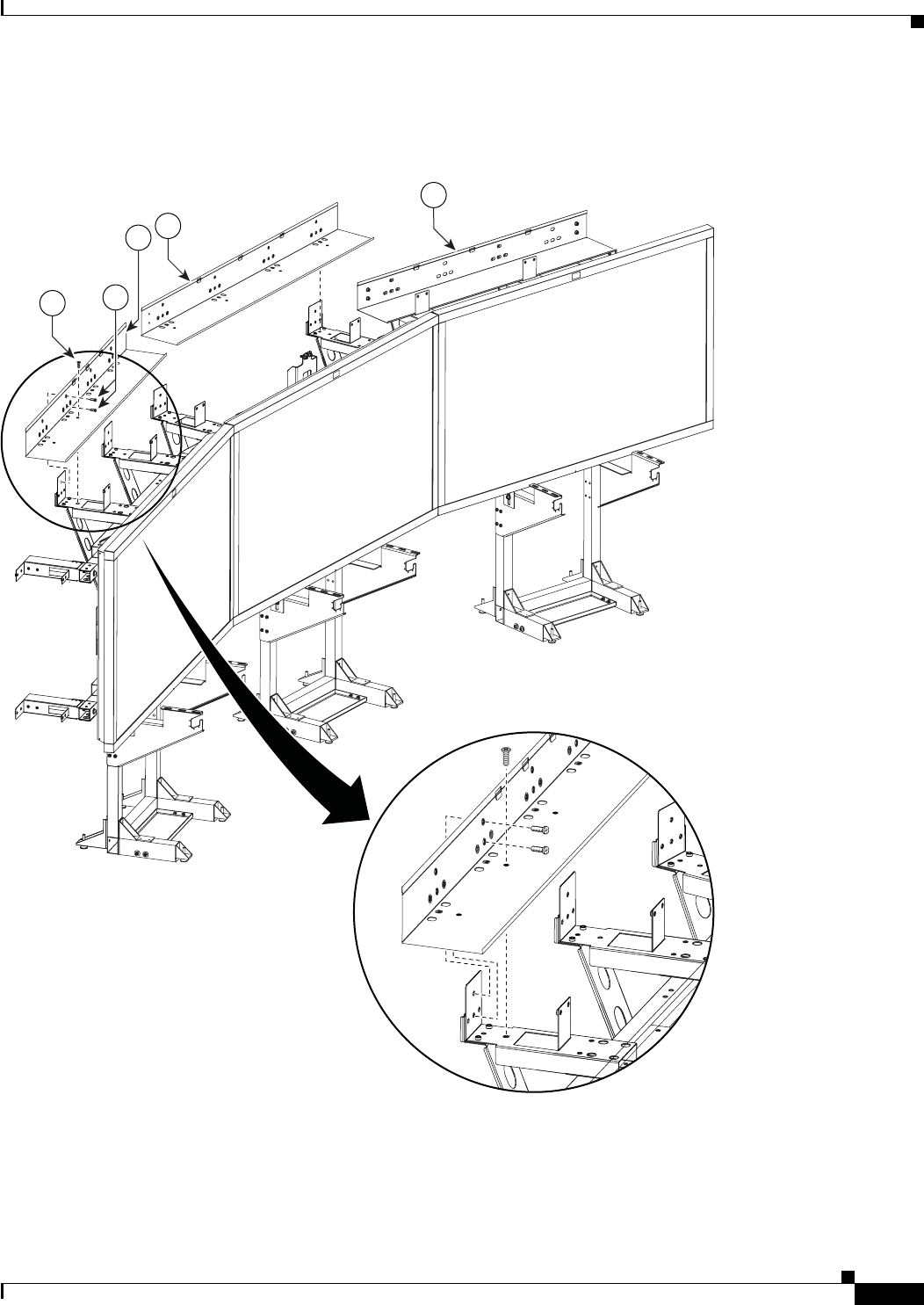
Step 1 Attach the Leveling feet to the Rear and Front Foot stabilizers.
Figure 2-1 Leveling feet
Note Figure 2-9 shows the correct positioning of the display structure; keep this in mind as you build the
structure.
201100
3
2
4

2-3
Cisco TelePresence System 3200
OL-14521-01
Chapter 2 Building the Display Assembly
Parts List
Step 2 Attach the Codec Safety trays to the Front Foot stabilizers.
Note If you ordered a Presentation Codec, attach the larger tray that comes with the Presentation Codec
package, part no. 700-25301-01, in the center display. Refer to the Cisco TelePresence Hardware
Options and Upgrade Guide for more information.
Figure 2-2 Codec Safety trays
201102
8
1112
2-4
Cisco TelePresence System 3200
OL-14521-01
Chapter 2 Building the Display Assembly
Parts List
Step 3 Attach the Rear and Front Foot stabilizers to the Display structures.
Figure 2-3 Rear and Front Foot stabilizers
201101
3
12 11
2
1
2-5
Cisco TelePresence System 3200
OL-14521-01
Chapter 2 Building the Display Assembly
Parts List
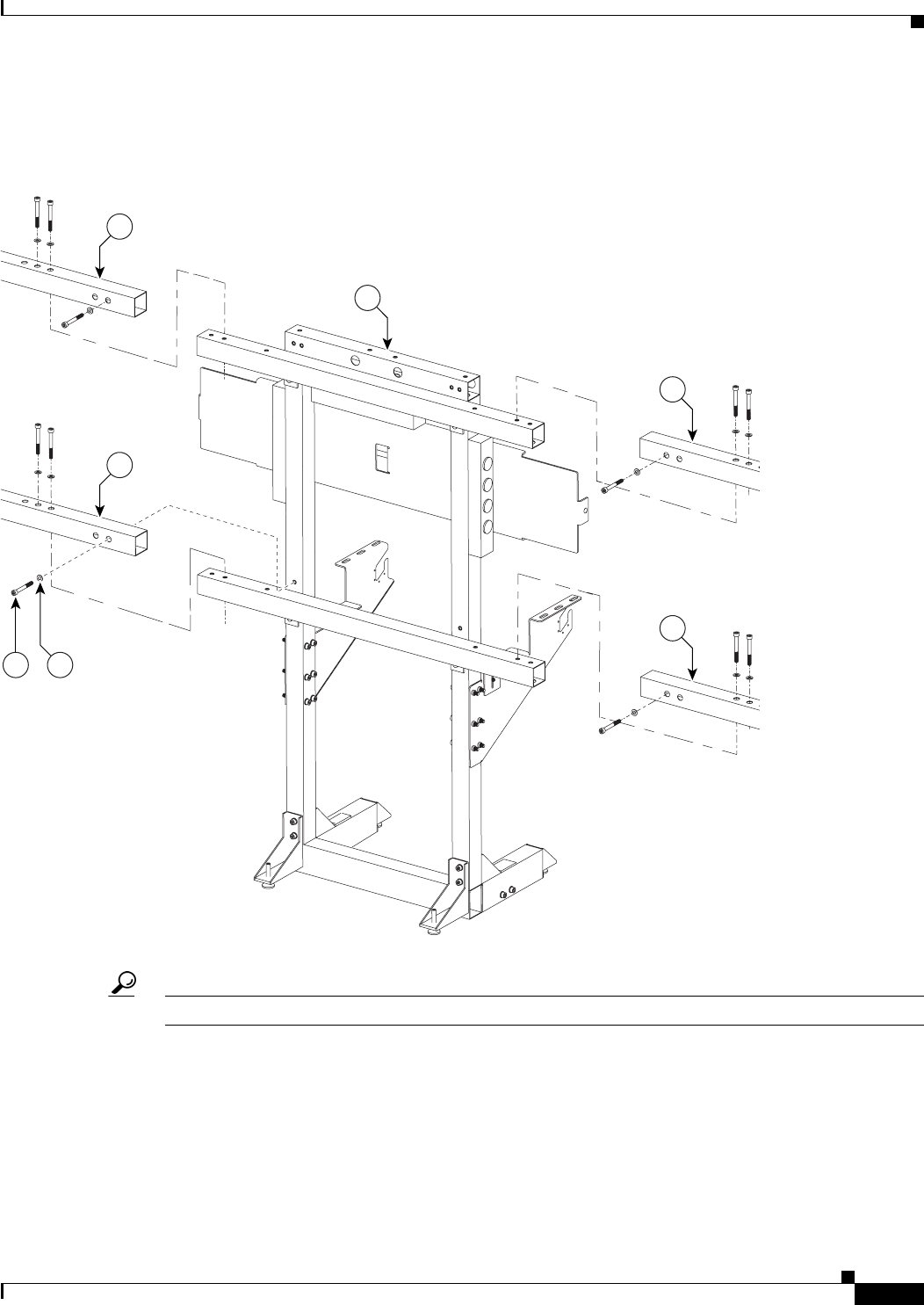
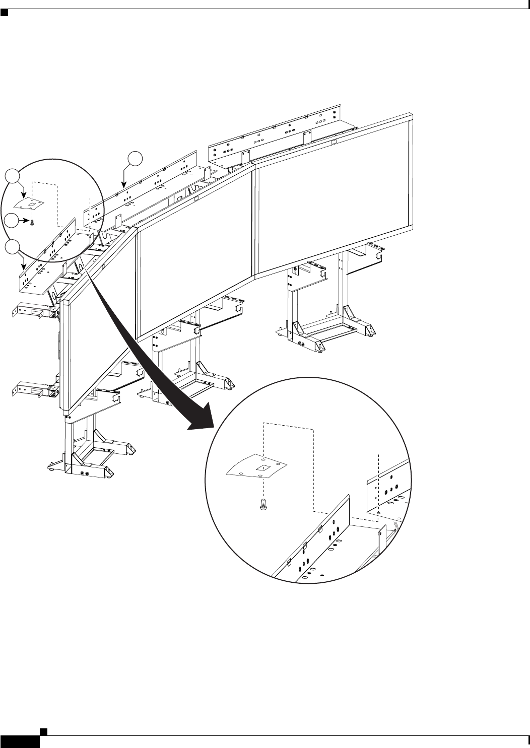
Step 4 Attach the left and right Display Shelf supports to each Display structure.
Figure 2-4 Left and Right Display Shelf supports
201103
512
11
6
1
2-6
Cisco TelePresence System 3200
OL-14521-01
Chapter 2 Building the Display Assembly
Parts List
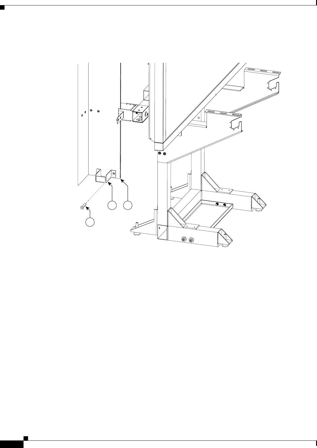
Step 5 Attach the Display Tilt brackets to each Display structure.
Figure 2-5 Display Tilt brackets
Note Do not tighten the Display Tilt brackets. You will need to adjust them to level the Plasma displays in
Chapter 3, “Mounting and Leveling the Plasma Displays.”
201104
713
12
7
1
2-7
Cisco TelePresence System 3200
OL-14521-01
Chapter 2 Building the Display Assembly
Parts List
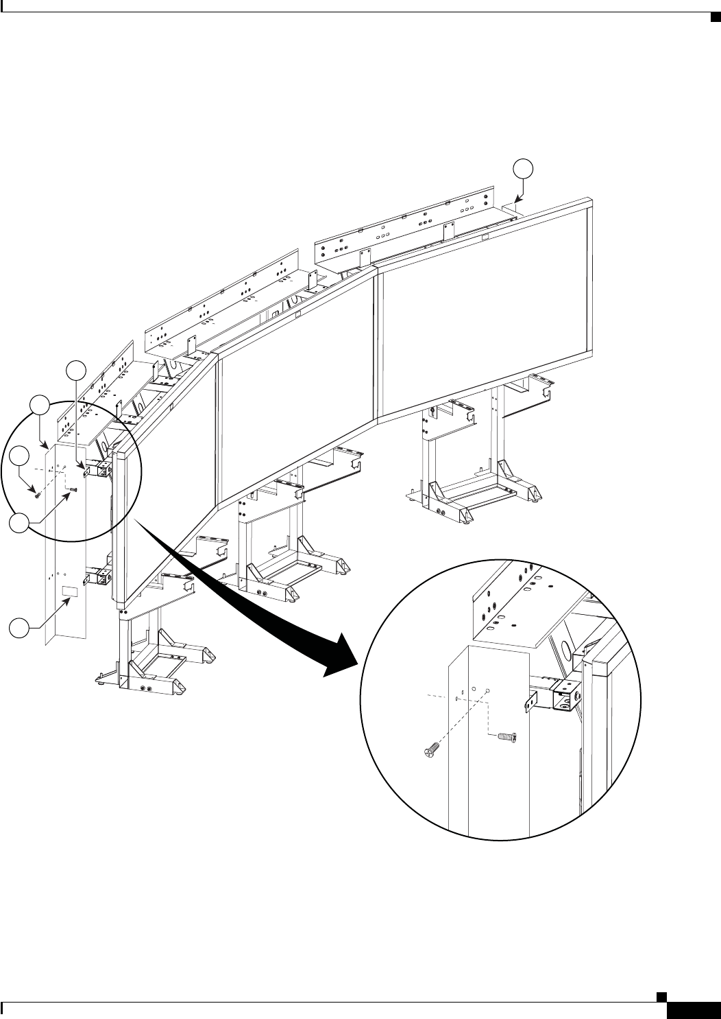
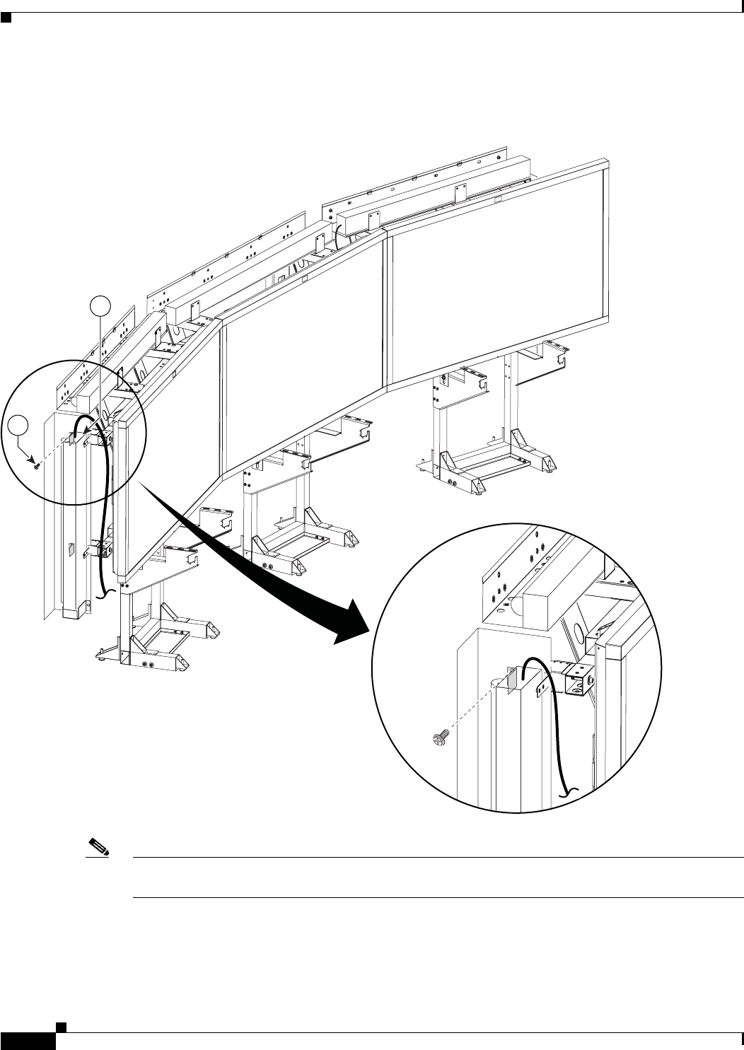
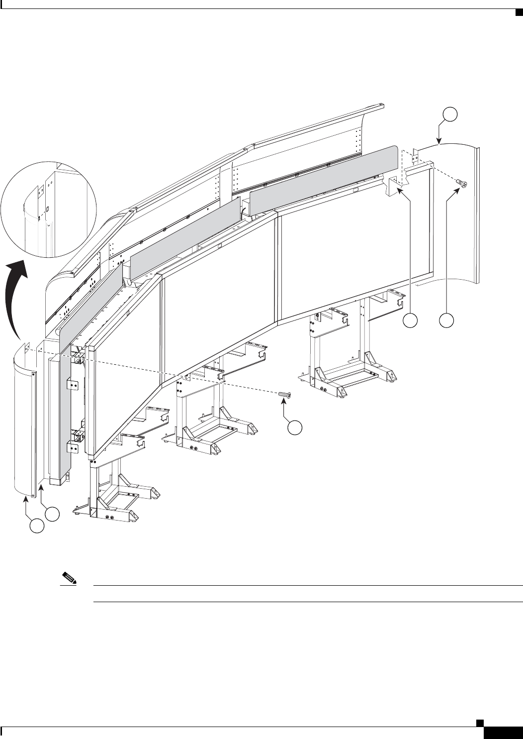
Step 6 Attach the Camera Assembly bracket to the center Display structure, making sure that this structure uses
the larger codec tray.
Figure 2-6 Camera Assembly bracket
Note The Camera Assembly bracket attaches to the center Display structure.
201105
1
9
13 13
2-8
Cisco TelePresence System 3200
OL-14521-01
Chapter 2 Building the Display Assembly
Parts List
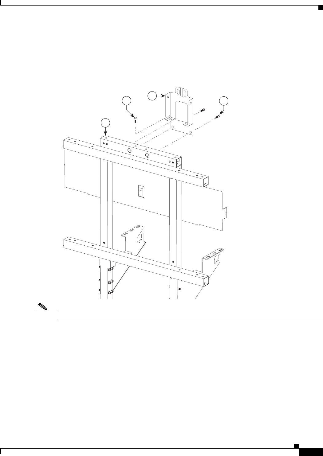
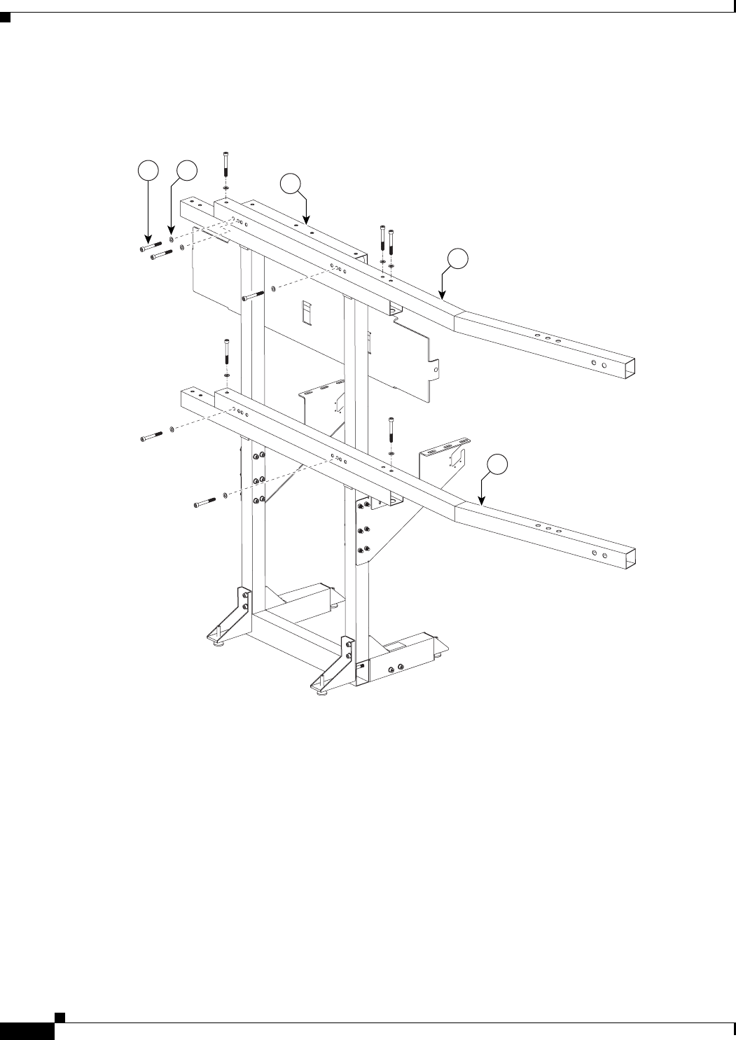
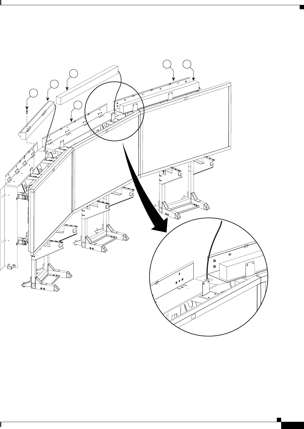
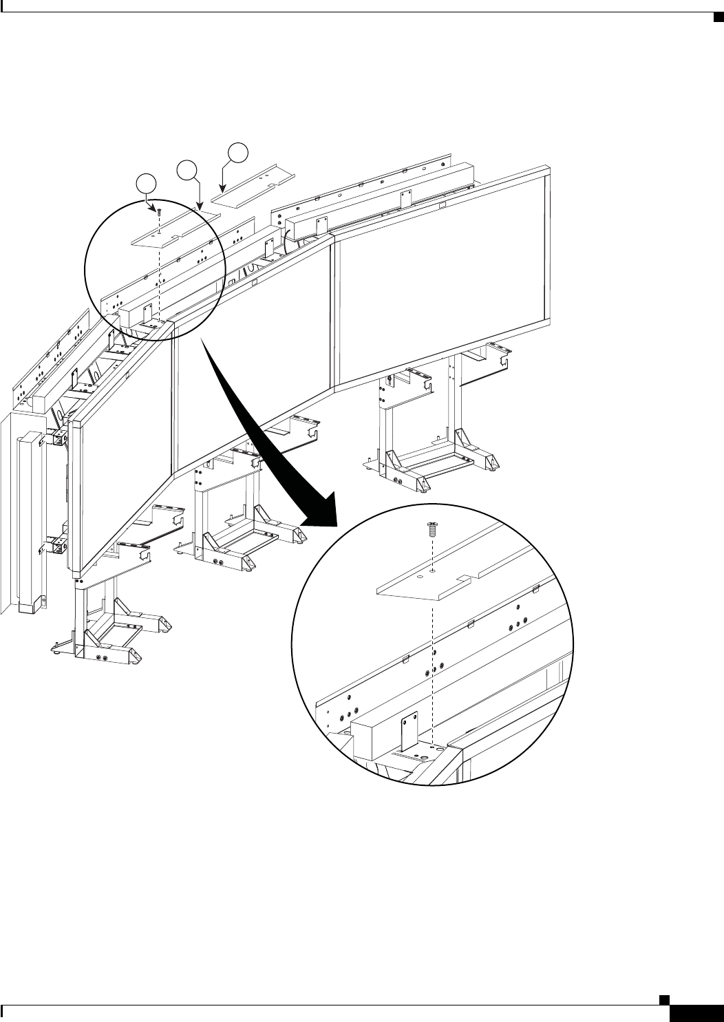
Step 7 Attach the upper and lower Support crossbars to the left and right Display structures.
Figure 2-7 Upper and Lower Support crossbars
201107
10
12
10
1
11
2-9
Cisco TelePresence System 3200
OL-14521-01
Chapter 2 Building the Display Assembly
Parts List
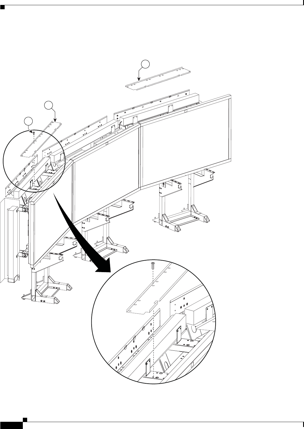
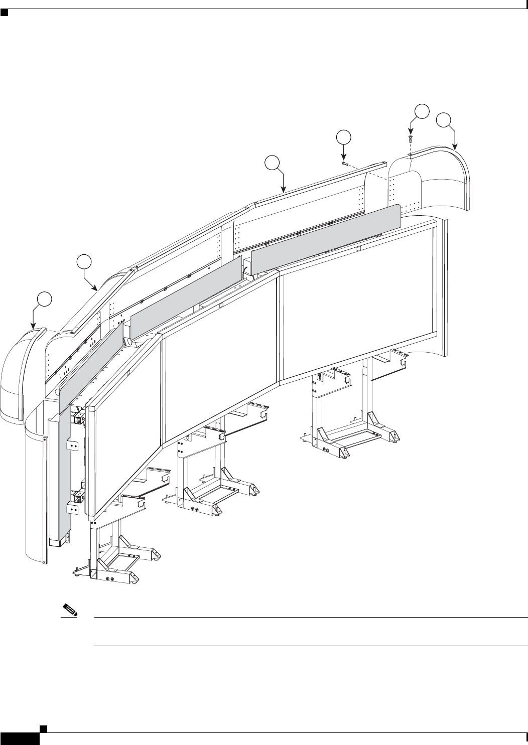
Step 8 Attach the upper and lower Support crossbars to the center Display structure.
Figure 2-8 Upper and Lower Support crossbars
Tip Use the screw holes nearest the ends of the Support crossbars.
201108
10
12
10
1
10
10
11
2-10
Cisco TelePresence System 3200
OL-14521-01
Chapter 2 Building the Display Assembly
Parts List
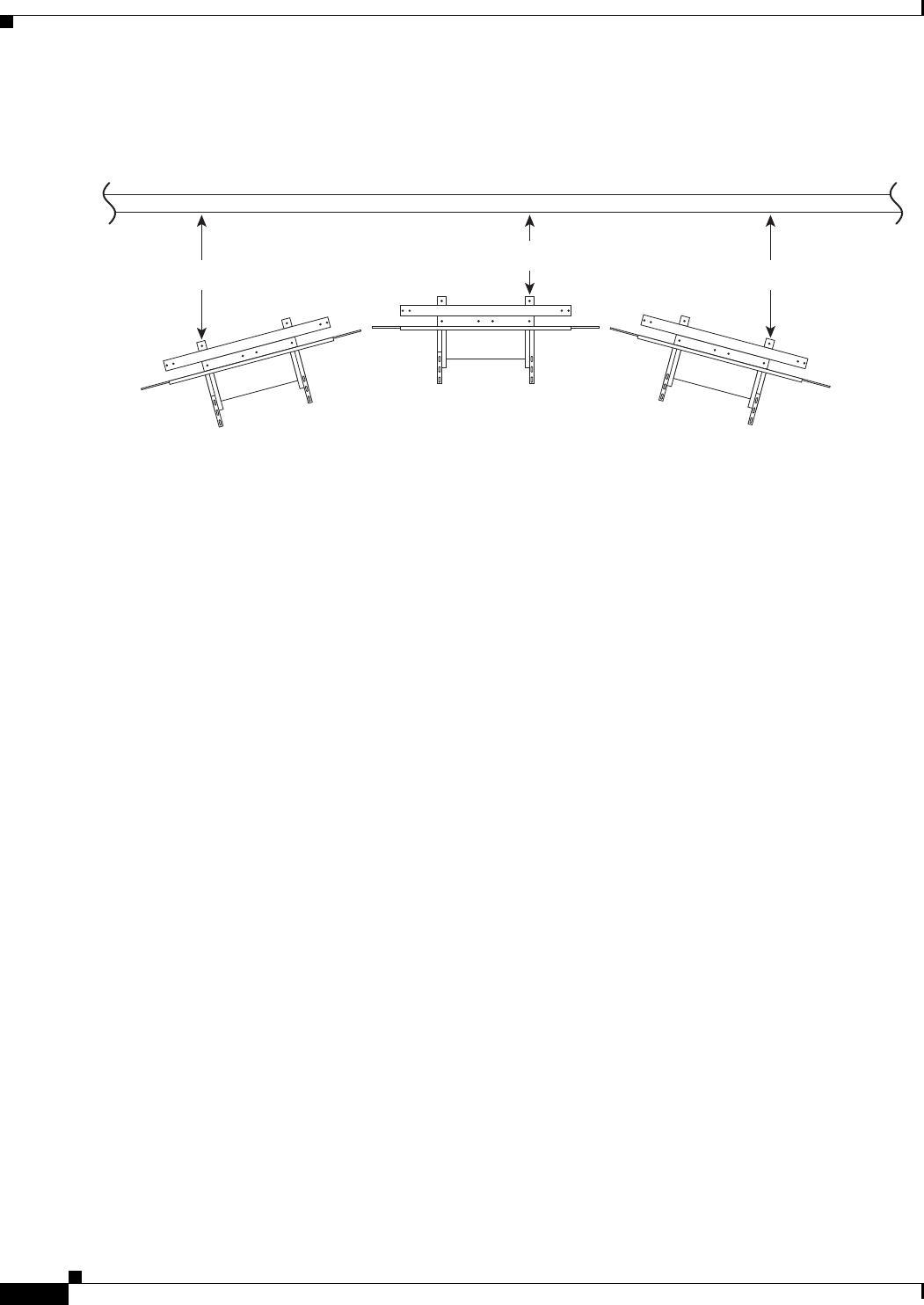
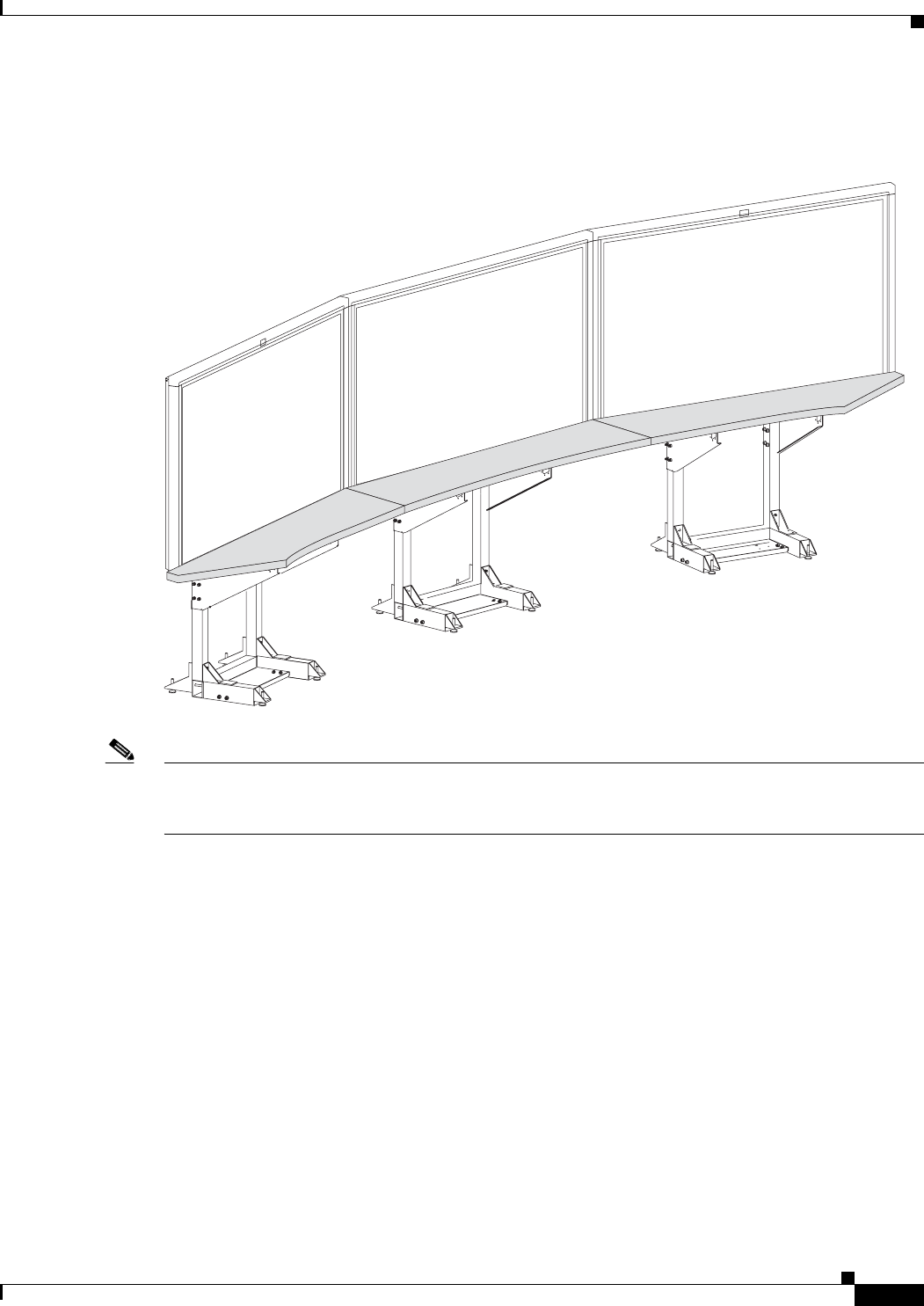
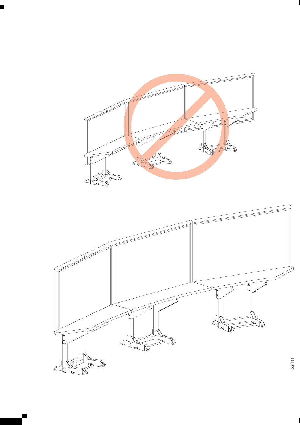
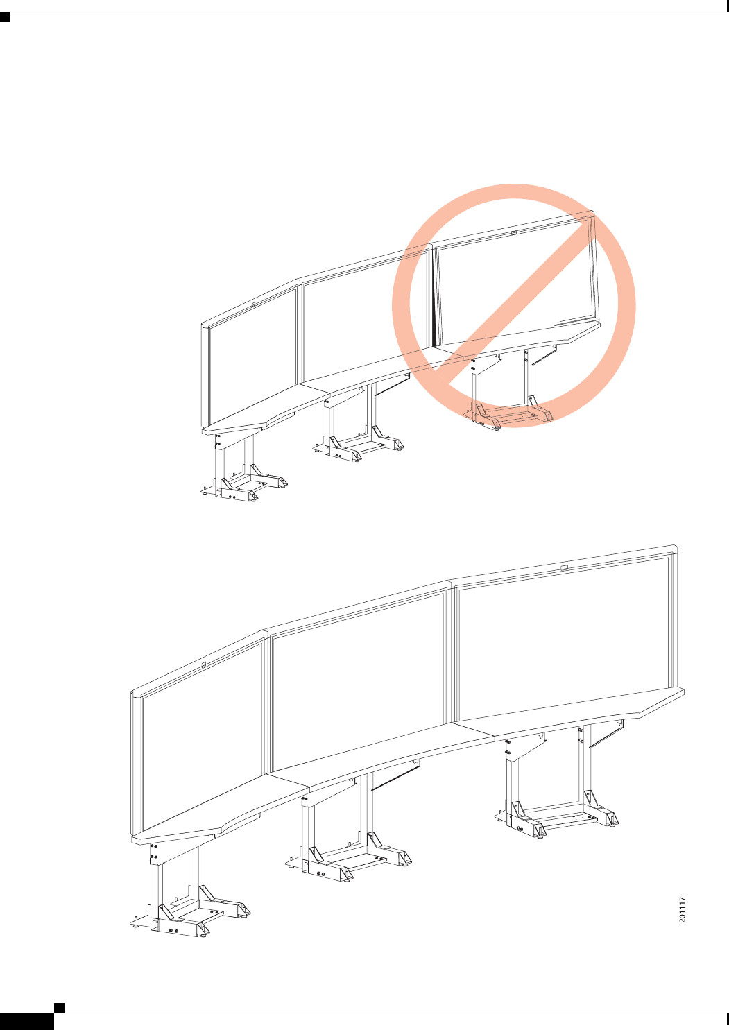
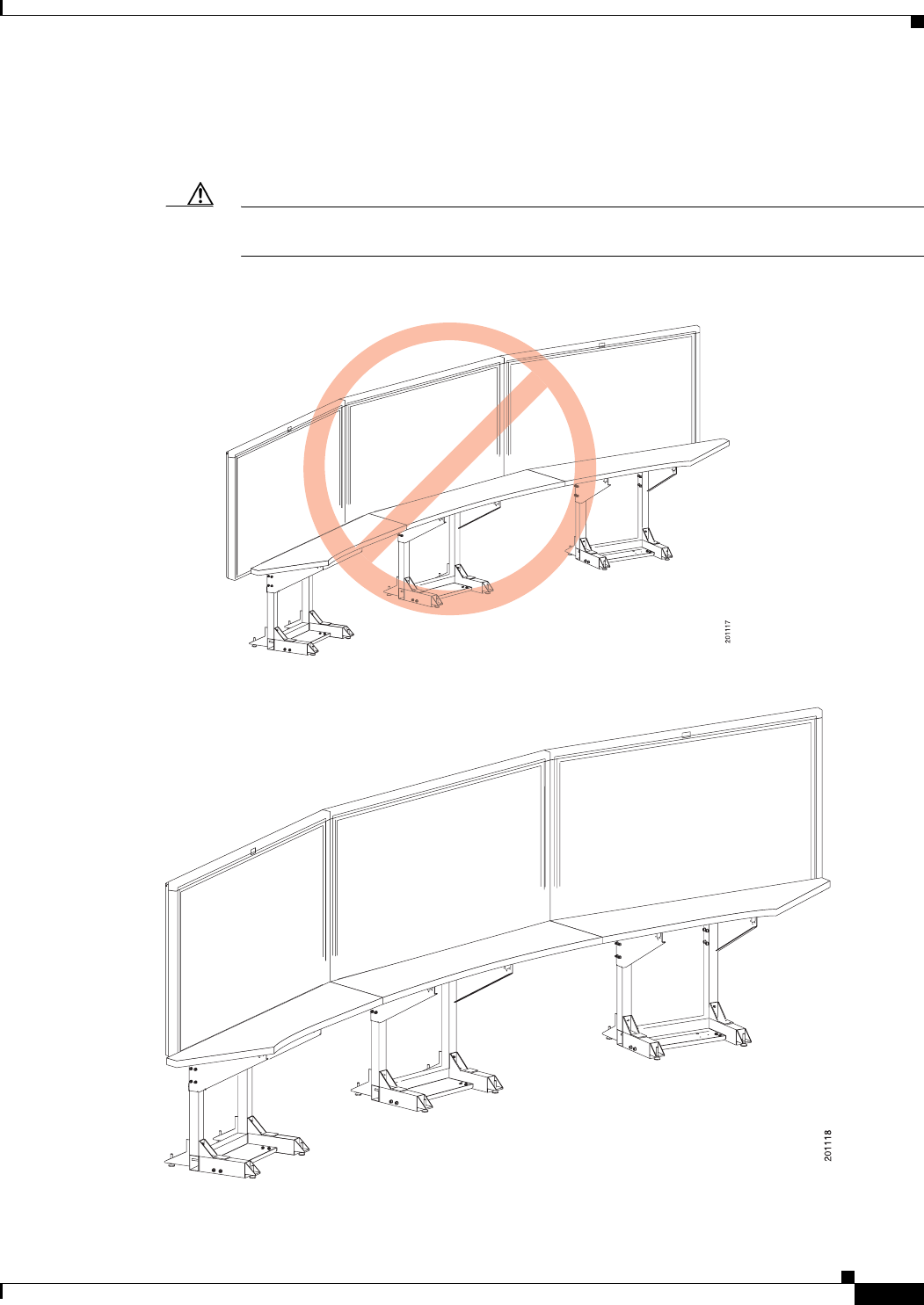
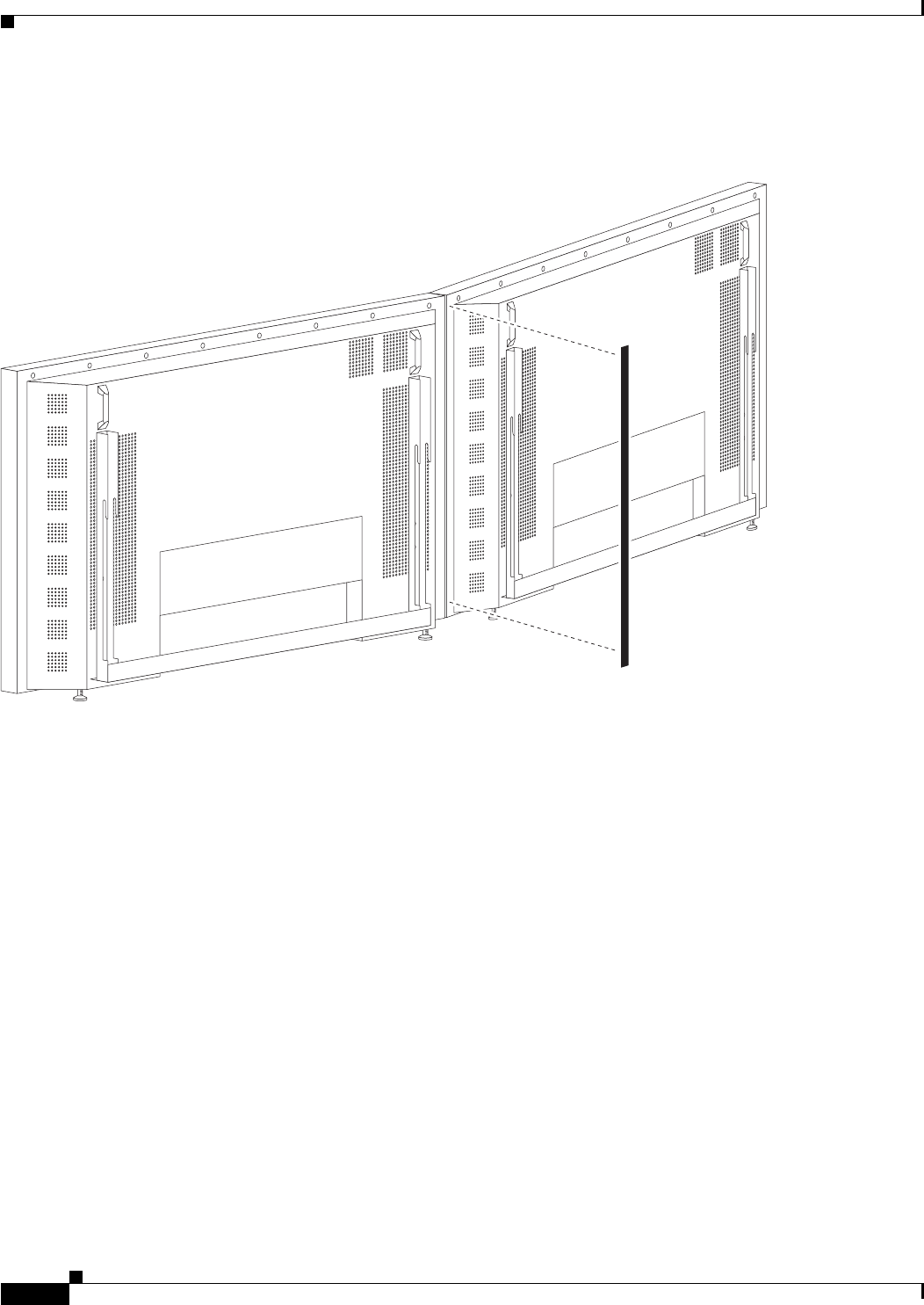
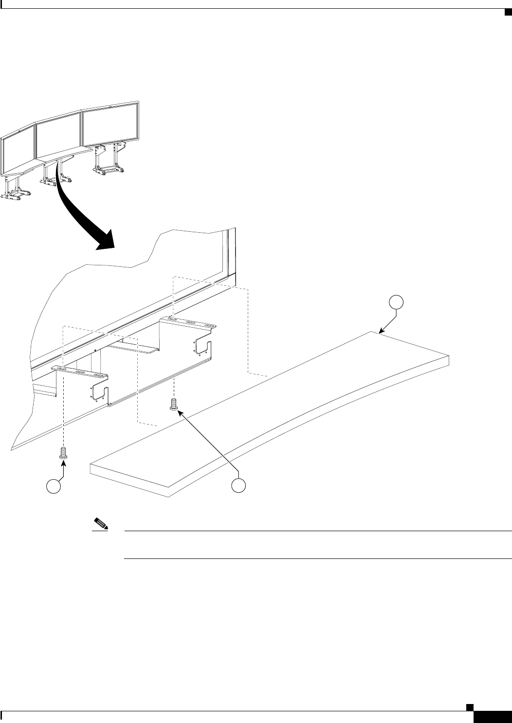
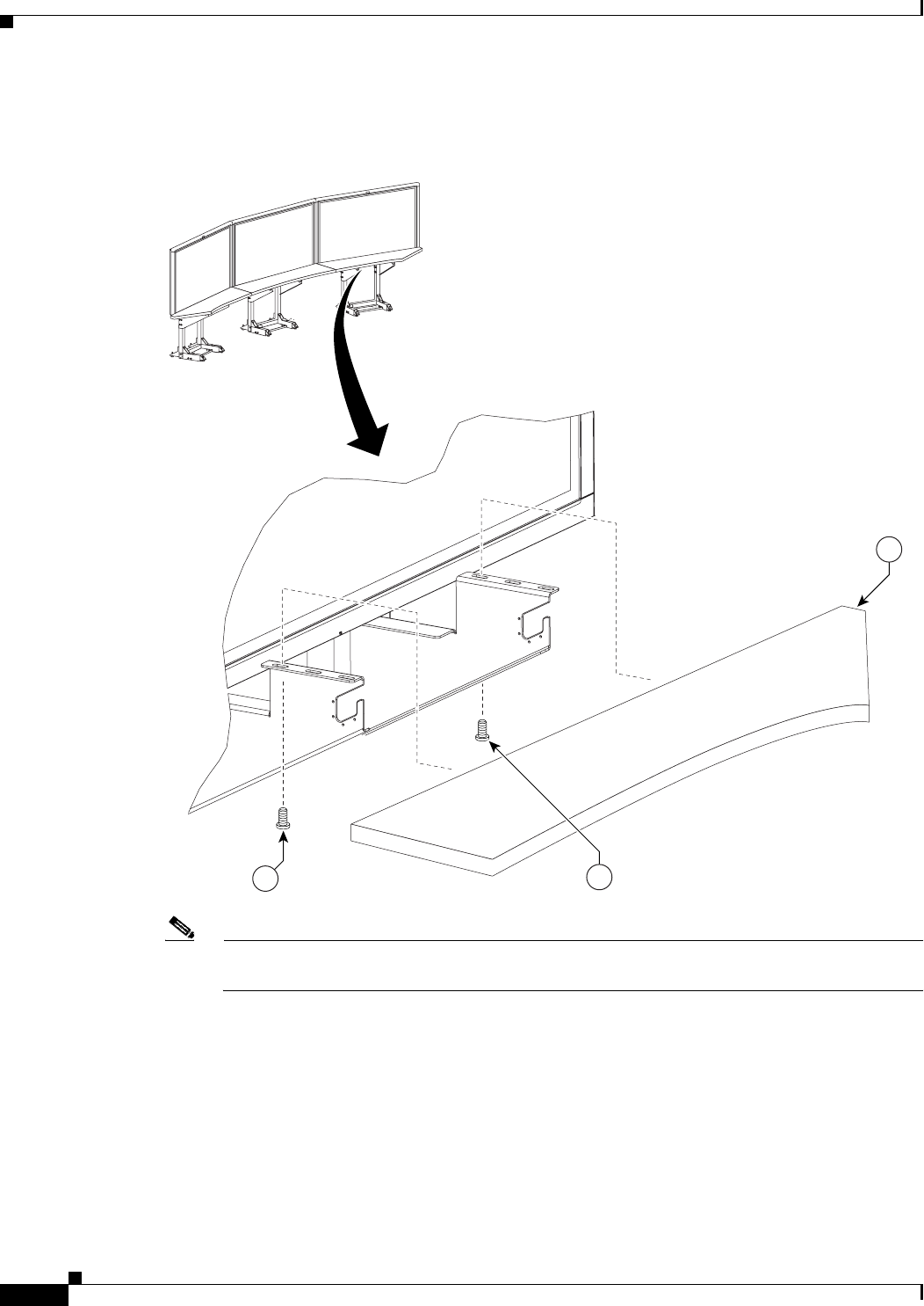
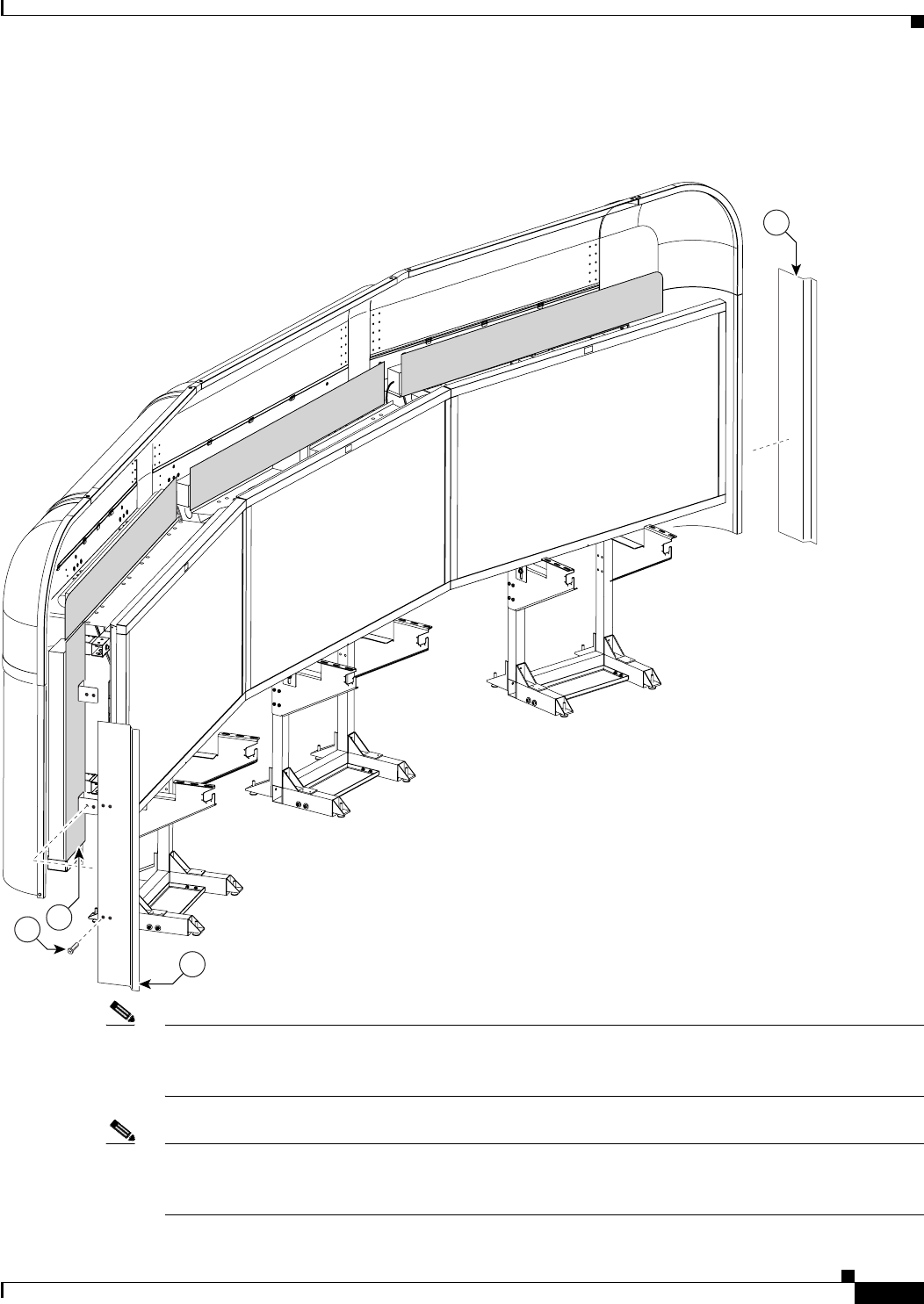
Step 9 Position the three Display structures relative to the rear wall.
Figure 2-9 Positioning the Display Structures
204152
18 - 22” (45.7 cm - 55.8 cm)
32 - 36” (81 cm - 91 cm) 32 - 36” (81 cm - 91 cm)

CHAPTER
3-1
Cisco TelePresence System 3200
OL-14521-01
3
Mounting and Leveling the Plasma Displays
Revised: July 28, 2008, OL-14521-01
Parts List
Warning
Only trained and qualified personnel should be allowed to install, replace, or service this equipment.
Note The directions left and right refer to the assembly as you face the Plasma displays.
Note Figure 3-3 through Figure 3-8 illustrate the process of leveling the Plasma displays. You may want to
review all of this chapter before beginning the leveling process.
Key Part Description Part Number Qty Ctn Notes
165-inch high-definition display CTS-DISP-65-
GEN2
74-4881-xx
323,
24,
25
2Black buffer strips 700-23981-xx 2 1
Display shelf section: left 95-9692-xx
Kit #
74-5304-xx
1 58 The Display shelves are used in this chapter for
leveling purposes only. The Display shelves and the
attaching bracketing hardware are described in
Chapter 5, “Building the Display Shelf Assembly.”
Display shelf section: center 95-9694-xx
Kit #
74-5306-xx
158
Display shelf section: right 95-9693-xx
Kit #
74-5305-xx
158
M8 x 20 mm screws 48-2273-01 1
3-2
Cisco TelePresence System 3200
OL-14521-01
Chapter 3 Mounting and Leveling the Plasma Displays
Parts List
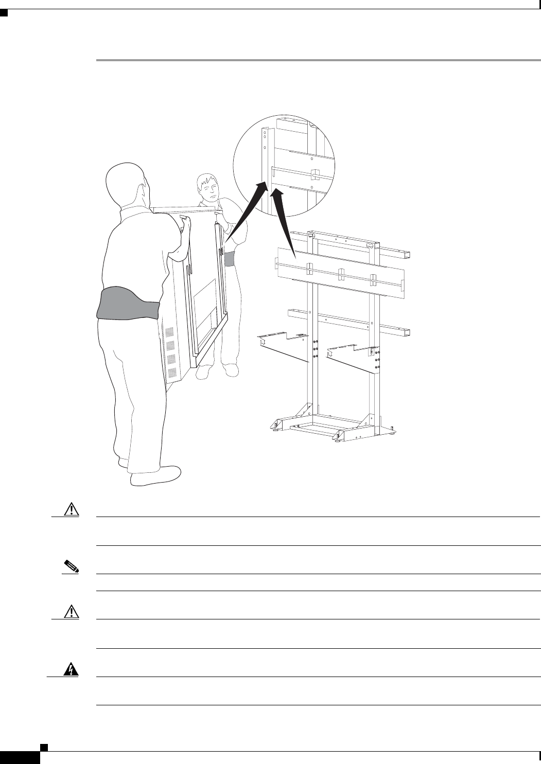
Step 1 Hang the left, center, and right Plasma displays on the Display structure crossbars.
Figure 3-1 The left, center, and right Plasma displays
Caution The edges of the Plasma displays are sharp and uncomfortable to lift with bare hands. Nonslip gloves
are recommended.
Note Make sure the Plasma display Leveling feet remain firmly seated on top of the Display shelf supports.
Caution Do not lift the display without appropriate back support, foot protection (such as steel-toed shoes), and
room to lift the display using your legs and not your back.
Warning
The displays are heavy and may cause injury or damage if care is not taken to support them properly
while mounting. Use caution and additional assistance as needed.
201109
3-3
Cisco TelePresence System 3200
OL-14521-01
Chapter 3 Mounting and Leveling the Plasma Displays
Parts List
Step 2 Loosely attach the Display shelves to the Display shelf supports.
Figure 3-2 Loosely Attach the Display shelves to the Display Shelf Supports
Note The Display shelves are used in this chapter for leveling purposes only. See Chapter 5, “Building the
Display Shelf Assembly” and use the M8 x 20 mm screws in the Accessory Kit to attach the display
shelves.
201111
3-4
Cisco TelePresence System 3200
OL-14521-01
Chapter 3 Mounting and Leveling the Plasma Displays
Purpose of Leveling the Plasma displays
Purpose of Leveling the Plasma displays
The three Plasma displays act as windows allowing a three-way view into the remote Cisco TelePresence
conference room. The Display shelf in front of each Plasma display acts as a visual bridge between the
local and remote conference rooms. In order to provide the experience of one seamless conference area,
the Display shelf must appear seamlessly integrated with the remote conference tables.
Leveling Alignment Points
Step 3 Use the leveling alignment points to level and align the Plasma displays.
Figure 3-3 Leveling Alignment Points
Note You can use a 5 mm hex key to adjust the display structure’s front and rear Foot Levelers.
201113
3-5
Cisco TelePresence System 3200
OL-14521-01
Chapter 3 Mounting and Leveling the Plasma Displays
Purpose of Leveling the Plasma displays
Leveling Goals
Leveling the Display shelves and the Plasma displays, and aligning the seams of the Display shelves with
the edges of the Plasma displays ensure that images displayed from the remote conference room match
the local conference room configuration.
The leveling goals illustrated in Figure 3-4 through Figure 3-8 show how to use the leveling alignment
points in Figure 3-3. You may need to perform any or all of the illustrated goals several times while
aligning and leveling the Plasma displays, and make additional adjustments later if the displays have
settled.
Step 4 Use the four Leveling feet on each Display structure to level the Display shelves along the X and Y axes.
Leveling the Display shelves ensures the Display structures are level. The Display structures should be
level before attempting to level the Plasma displays.
Figure 3-4 Level the Display shelves along the X and Y axes
201114
3-6
Cisco TelePresence System 3200
OL-14521-01
Chapter 3 Mounting and Leveling the Plasma Displays
Purpose of Leveling the Plasma displays
Step 5 The surface of the Display shelves should not obstruct any lines of resolution. Use the Plasma display
Leveling feet to raise or lower the Plasma displays and make sure all lines of resolution can be seen when
sitting at both the first and second conference tables.
Figure 3-5 Make sure no lines of resolution are blocked by the Display shelves
3-7
Cisco TelePresence System 3200
OL-14521-01
Chapter 3 Mounting and Leveling the Plasma Displays
Purpose of Leveling the Plasma displays
Step 6 Use the Plasma display Leveling feet to level the Plasma displays along the X axis.
Use the Display tilt brackets to level the Plasma displays along the Y axis.
Tip You should level the center Plasma display first. Then align the left and right Plasma displays to the
center display.
Figure 3-6 Level the Plasma displays along the X and Y axes
Caution Do not place the level against the Plasma display screen. Place the level against the Plasma display bezel.
201116
3-8
Cisco TelePresence System 3200
OL-14521-01
Chapter 3 Mounting and Leveling the Plasma Displays
Purpose of Leveling the Plasma displays
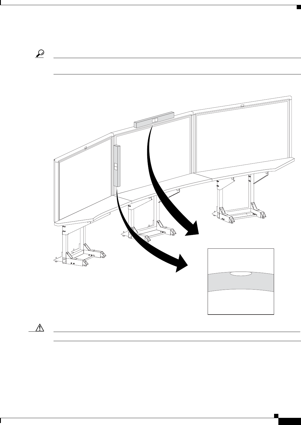
Step 7 Align the edges of Plasma displays
The gap between Plasma displays should be uniformly even from the top edge of the Plasma display to
the bottom edge. You should try to make the gap as small as possible.
Figure 3-7 Align the edges of Plasma displays
3-9
Cisco TelePresence System 3200
OL-14521-01
Chapter 3 Mounting and Leveling the Plasma Displays
Purpose of Leveling the Plasma displays
Step 8 Align the seams of the Display shelves with the seams between Plasma displays.
You may need to adjust the Plasma displays left to right so the seam created between the edges of two
Plasma displays are aligned to the corresponding Display shelf seam.
Caution While moving the Plasma display to the left or right you need to make sure the Plasma display
Leveling feet remain firmly seated on top of the Display shelf supports.
Figure 3-8 Align the seams of the Display shelves with the seams between Plasma displays
3-10
Cisco TelePresence System 3200
OL-14521-01
Chapter 3 Mounting and Leveling the Plasma Displays
Purpose of Leveling the Plasma displays
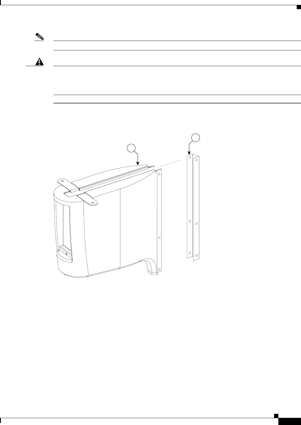
Step 9 Complete the plasma display screen setup by applying the Black Buffer strips.
Figure 3-9 Apply the Black Buffer strips
201119

CHAPTER
5-1
Cisco TelePresence System 3200
OL-14521-01
5
Building the Display Shelf Assembly
Revised: July 28, 2008, OL-14521-01
Parts List
Display Shelf, Type 1
Key Part Description Part Number Qty Ctn Notes
1Display shelf section: left 95-9692-xx
Kit # 74-5304-xx
158
2Display shelf section: center 95-9694-xx
Kit # 74-5306-xx
158
3Display shelf section: right 95-9693-xx
Kit # 74-5305-xx
158
4Not used
5Left accessory cabinet attachment bracket 700-23336-xx 1 19
6Right accessory cabinet attachment bracket 700-23337-xx 119
7Not used
8Connecting plates 700-23345-xx 213
9Speaker board brackets 700-23944-xx 613
10 Splines No part number 258
11 Draw bolts 51-4579-xx 658
12 M8 x 20 mm screws 48-2273-01 1
13 M8 x 30 mm screw 48-2313-01 15 1
Accessory Cabinet
1Accessory Cabinet, Right 74-5297-xx
Kit # 69-1837-xx
147
2Accessory Cabinet, Left 74-5298-xx
Kit #69-1838-xx
148
5-2
Cisco TelePresence System 3200
OL-14521-01
Chapter 5 Building the Display Shelf Assembly
Parts List
Caution The shelf segments are unstable during assembly. Use caution, and support all structures as required.
Warning
Only trained and qualified personnel should be allowed to install, replace, or service this equipment.
Caution In order to prevent scratching the Display shelves, you should avoid putting any tools on the shelf
surfaces.
Note The directions left and right refer to the assembly as you face the Plasma displays.
3Assembly Screen Supports No part number 2Located inside of assembly cabinet.
These brackets are only required if
you use a Type 1 projector screen,
part number 800-28681-01. If your
installation uses the projector
screen with a product ID of
CTS3K-SCREEN and a part
number of 74-5416-01, do not
install these brackets.
4M8 x 20 mm screws 48-2273-01 14 1
Display Shelf, Type 1
Key Part Description Part Number Qty Ctn Notes
5-3
Cisco TelePresence System 3200
OL-14521-01
Chapter 5 Building the Display Shelf Assembly
Parts List
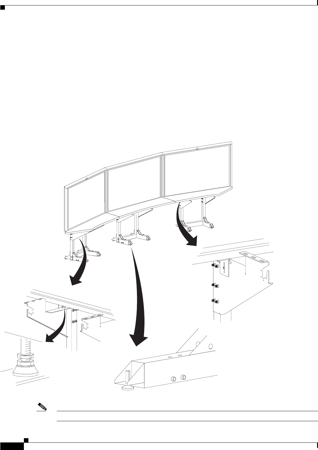
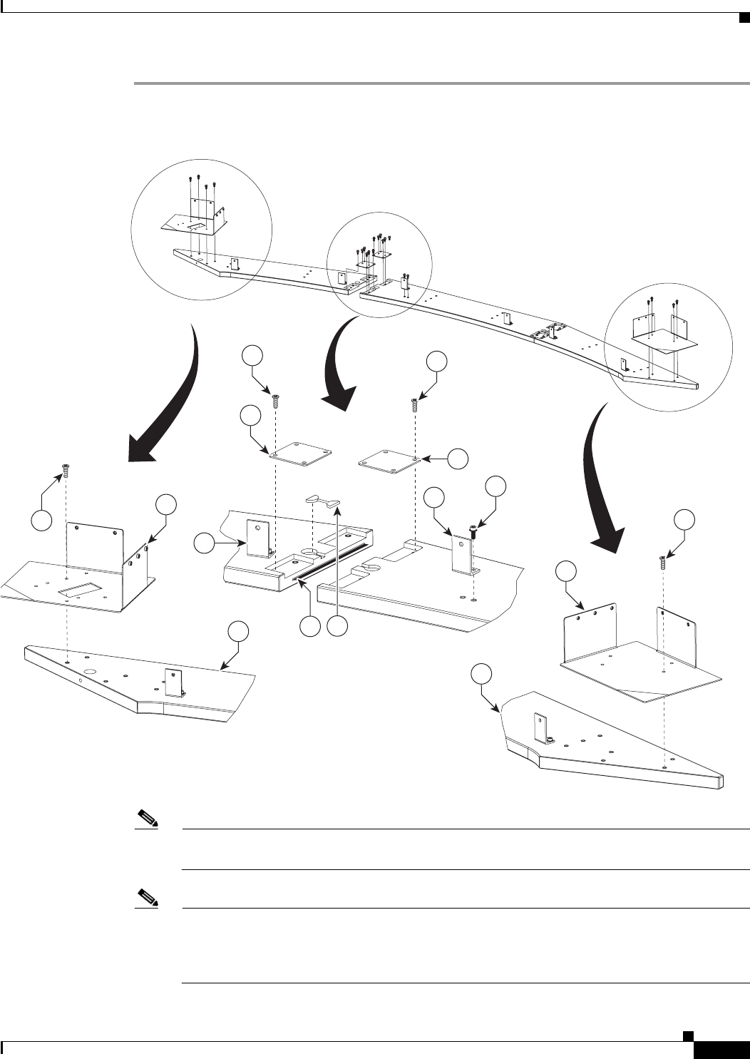
Step 1 Attach the Display shelf hardware.
Figure 5-1 Display shelf hardware
Note The Right Accessory Cabinet attachment bracket (marked “6” in the illustration), has a central
rectangular hole that differentiates it from the Left Accessory Cabinet attachment bracket.
Note This illustration describes the hardware used to attach the three Display shelves and the
hardware used to attach additional assemblies in Chapter 8, “Assembling the Remaining
Cisco TelePresence Elements.” The Display shelves should be attached individually to the
Display structures, as illustrated in Figure 5-2, Figure 5-3, and Figure 5-4.
12
5
3
1
12
6
205467
8
9
12
10 11
9
14
14
8
5-4
Cisco TelePresence System 3200
OL-14521-01
Chapter 5 Building the Display Shelf Assembly
Parts List
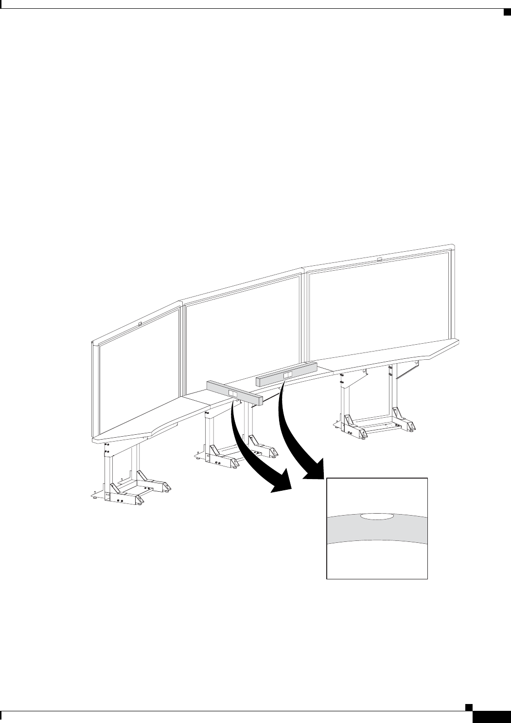
Step 2 Attach the left Display shelf.
Figure 5-2 Left Display shelf
201148
1
13 13
5-7
Cisco TelePresence System 3200
OL-14521-01
Chapter 5 Building the Display Shelf Assembly
Parts List
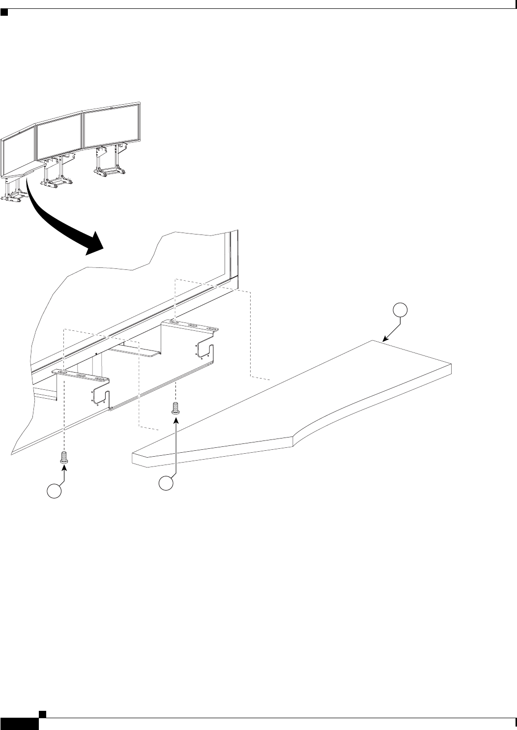
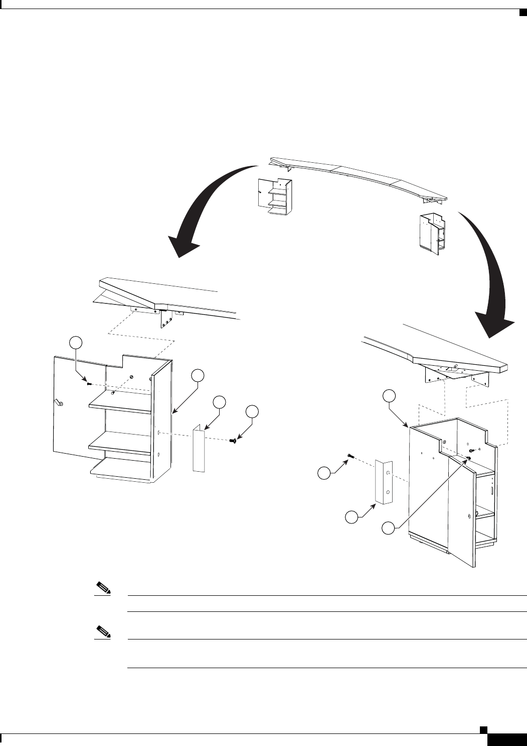
Step 5 Attach the screen supports to the accessory cabinets and position, but do not attach, the cabinets to the
left and right attachment brackets
These screen supports are only required if you use a Type 1 projector screen, part number 800-28681-01.
If your installation uses the projector screen with a product ID of CTS3K-SCREEN and a part number
of 74-5416-01, do not install these brackets.
Figure 5-5 Accessory Cabinet
Note One wall of the left Accessory cabinet was removed from this illustration for clarity.
Note Before you attach the Accessory cabinets to the brackets, use them as supports while assembling
the table segments in Chapter 6, “Building the First Row Table Assembly.”
204159
12
3
4
1
2
3
4
12

5-8
Cisco TelePresence System 3200
OL-14521-01
Chapter 5 Building the Display Shelf Assembly
Parts List

CHAPTER
4-1
Cisco TelePresence System 3200
OL-14521-01
4
Building the Lighting Assembly
Revised: July 28, 2008, OL-14521-01
Parts List
Key Part Description Part Number Qty Ctn Notes
1Lighting support brackets 700-23749-xx 6 49
2Support struts 700-23752-xx 6 49
3End structure brackets 700-23750-xx 4 49
4Plastic diffuser panel: center 700-23745-xx 1 49
5Plastic diffuser panel: ends 700-23746-xx 2 49
6Plastic diffuser panel: top right 700-23747-xx 1 49
7Plastic diffuser panel: top left 700-23748-xx 1 49
8L-bracket 700-23899-xx 4 49
9Metal trim panel: center left 700-24126-xx 1 49
10 Metal trim panel: top side 700-23897-xx 2 49
11 Metal trim panel: end 700-23898-xx 2 49
12 Metal trim panel: center right 700-23896-xx 1 49
13 Reflector bottom tray: center 700-23826-xx 1 49
14 Reflector bottom tray: left side top 700-23827-02 1 49
15 Reflector bottom: left end 700-23828-02 1 49
16 Reflector bottom spacer 700-24152-xx 2 49
17 Reflector top: center 700-23731-xx 1 49
18 Reflector top: top side 700-23734-xx 2 49
19 Reflector top: end 700-23735-xx 2 49
20 Reflector transition piece: left 700-23756-xx 1 49
21 Reflector transition piece: right 700-23757-xx 1 49
22 Reflector transition piece: corner 700-23758-xx 2 49
4-2
Cisco TelePresence System 3200
OL-14521-01
Chapter 4 Building the Lighting Assembly
Parts List
Warning
Only trained and qualified personnel should be allowed to install, replace, or service this equipment.
Caution Metal and plastic edges can be sharp. Cisco recommends you wear safety gloves and safety glasses when
attaching the lighting assembly.
Note The directions left and right refer to the assembly as you face the Plasma displays.
23 Light “cup” bracket 700-23737-xx 2 43
24 5-foot center light fixture 74-4921-xx
Kit # 95-8932-xx
331See “Appendix B: Region- and
Country-Specific Equipment” for
Europe- and Japan-specific lighting
fixtures.
25 4-foot side light fixture 74-5362-xx
Kit # 95-8932-xx
230,
31
See “Appendix B: Region- and
Country-Specific Equipment” for
Europe- and Japan-specific lighting
fixtures.
26 M8 x 70 mm screws 48-2274-xx 10 1
27 M8 x 16 mm pan head screw, white 48-2432-xx 1
28 M8 x 20 mm flat head screw, white 48-2433-xx 10 49
29 Diffuser Panel braces / H-clips 700-25050-xx 2 49
30 Compliance sticker for plasma display 47-21525-xx 1 1
31 M8 x 16 mm pan head screw, black 48-2430-xx 2 1
32 Reflector bottom tray: right side top 700-27762-xx 1 49
33 Reflector bottom: right end 700-27763-xx 1 49
Touch-up paint, white 74-5247-xx 1 1 Use this paint on the light reflectors to fix
any minor cosmetic issues caused by
shipping and handling.
Key Part Description Part Number Qty Ctn Notes
4-3
Cisco TelePresence System 3200
OL-14521-01
Chapter 4 Building the Lighting Assembly
Parts List
Step 1 Assemble the six Support struts and six Lighting Support brackets.
Figure 4-1 Support struts and Lighting Support brackets
2
27
1
201125
4-4
Cisco TelePresence System 3200
OL-14521-01
Chapter 4 Building the Lighting Assembly
Parts List
Step 2 Attach the left and right outer Support brackets (from Figure 4-1) to the horizontal bar on the left and
right Display structures.
Figure 4-2 Left and Right outer Support brackets (from Figure 4-1)
Note Use any of the six brackets that you assembled in Step 1. There is no physical difference between
the outer and inner Support brackets in Figure 4-1.
2
1
31
31
201126
4-5
Cisco TelePresence System 3200
OL-14521-01
Chapter 4 Building the Lighting Assembly
Parts List
Step 3 Attach the four inner Support brackets to the Support crossbars.
Figure 4-3 Four inner Support brackets (from Figure 4-1)
Note Use any of the six brackets that you assembled in Step 1. There is no physical difference between
the outer and inner Support brackets in Figure 4-1.
201127
31
2
1
26
4-6
Cisco TelePresence System 3200
OL-14521-01
Chapter 4 Building the Lighting Assembly
Parts List
Step 4 Attach the four End structure brackets to the ends of the Support crossbars.
Figure 4-4 Four End structure brackets
201128
3
31
31
4-7
Cisco TelePresence System 3200
OL-14521-01
Chapter 4 Building the Lighting Assembly
Parts List
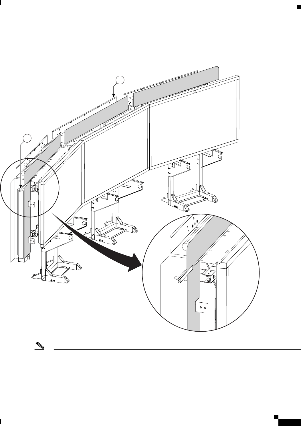
Step 5 Attach the three Reflector bottom trays to the Support brackets.
Figure 4-5 Three Reflector bottom trays
201129
27
32
13
27
14
4-8
Cisco TelePresence System 3200
OL-14521-01
Chapter 4 Building the Lighting Assembly
Parts List
Step 6 Attach the two Reflector bottom spacers to join the three Reflector bottom trays.
Figure 4-6 Two Reflector bottom spacers
201130
13
14
16
27
4-9
Cisco TelePresence System 3200
OL-14521-01
Chapter 4 Building the Lighting Assembly
Parts List
Step 7 Attach the left and right (vertical) Reflector Bottom ends to the End Structure brackets and attach the
compliance sticker to the left reflector bottom end.
Figure 4-7 Left and Right (vertical) Reflector Bottom ends
27
15
33
3
27
30
4-10
Cisco TelePresence System 3200
OL-14521-01
Chapter 4 Building the Lighting Assembly
Parts List
Step 8 Attach the Light Cup bracket to the left and right (vertical) Reflector Bottom ends.
Figure 4-8 Light Cup bracket
23
27
15
201132
4-11
Cisco TelePresence System 3200
OL-14521-01
Chapter 4 Building the Lighting Assembly
Parts List
Step 9 Attach the three 5-foot Light fixtures inside the Reflector bottoms.
Figure 4-9 Three 5-foot Light fixtures
24
24
27
13
2432
4-12
Cisco TelePresence System 3200
OL-14521-01
Chapter 4 Building the Lighting Assembly
Parts List
Step 10 Attach the left and right 4-foot Side Light fixtures to the left and right (vertical) Reflector Bottom ends.
Figure 4-10 Left and Right 4-foot Side Light fixtures
Note The power cords for the Side Light fixtures should extend from the top through the Light Cup bracket
(Figure 4-8).
27
25
201134
4-13
Cisco TelePresence System 3200
OL-14521-01
Chapter 4 Building the Lighting Assembly
Parts List
Step 11 Attach the two center Metal Trim panels.
Figure 4-11 Two center Metal Trim panels
12
9
201135
31
4-14
Cisco TelePresence System 3200
OL-14521-01
Chapter 4 Building the Lighting Assembly
Parts List
Step 12 Attach the two side Metal Trim panels.
Figure 4-12 Two side Metal Trim panels
34
10
31
201136
4-15
Cisco TelePresence System 3200
OL-14521-01
Chapter 4 Building the Lighting Assembly
Parts List
Step 13 Attach the center Plastic Diffuser panel.
Figure 4-13 Center Plastic Diffuser panel
201137
4
31
4-16
Cisco TelePresence System 3200
OL-14521-01
Chapter 4 Building the Lighting Assembly
Parts List
Step 14 Attach the left and right plastic diffuser panels. Before fully tightening the screws, adjust the panels to
the left or right to ensure that the spacing between the diffuser panels are even.
Figure 4-14 Left and Right Plastic Diffuser panels
Note The rounded corners of the left and right plastic diffuser panels point outward.
201138
7
6
31
4-17
Cisco TelePresence System 3200
OL-14521-01
Chapter 4 Building the Lighting Assembly
Parts List
Step 15 Attach the four L-brackets to the two (vertical) end Plastic Diffuser panels.
Figure 4-15 Four L-brackets
201139
5
31
8
4-18
Cisco TelePresence System 3200
OL-14521-01
Chapter 4 Building the Lighting Assembly
Parts List
Step 16 Attach the two (vertical) Plastic Diffuser panels to the End Structure brackets.
Figure 4-16 Two (vertical) Plastic Diffuser panels
5
31
201140
3
4-19
Cisco TelePresence System 3200
OL-14521-01
Chapter 4 Building the Lighting Assembly
Parts List
Step 17 Slide the Plastic Diffuser Panel brace between the end (vertical) Plastic Diffuser panel and the left and
right Plastic Diffuser panels.
Figure 4-17 Plastic Diffuser Panel brace
Note If a diffuser becomes scratched, use a black felt-tip permanent marker to cover the imperfection.
201202
13
29
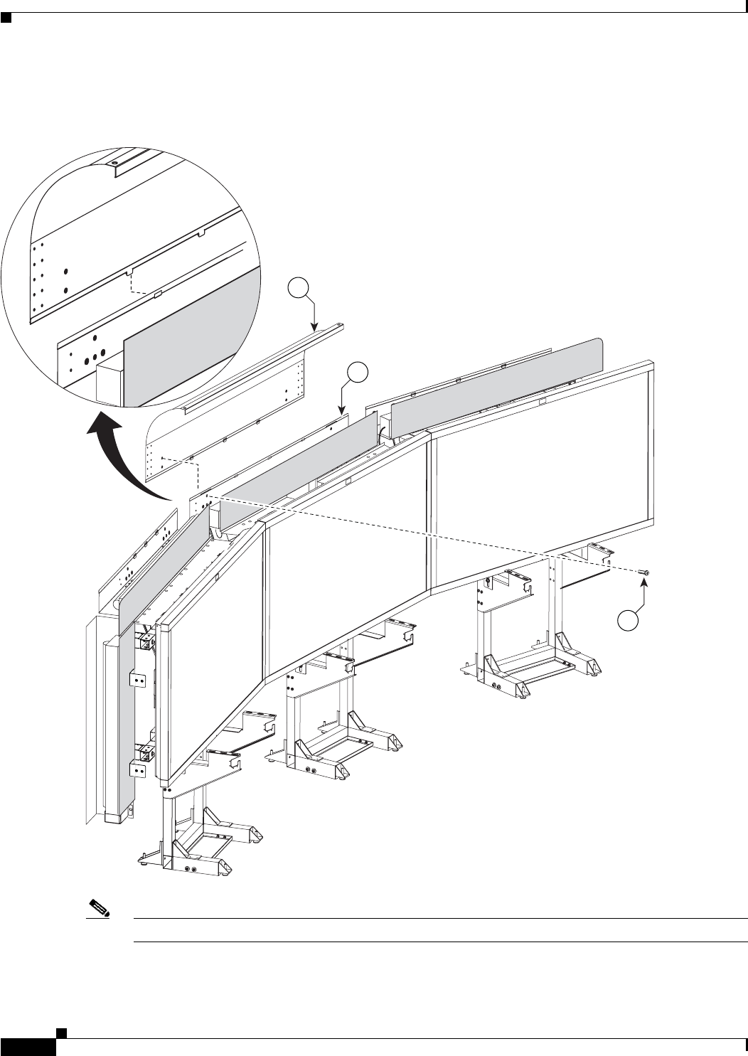
4-22
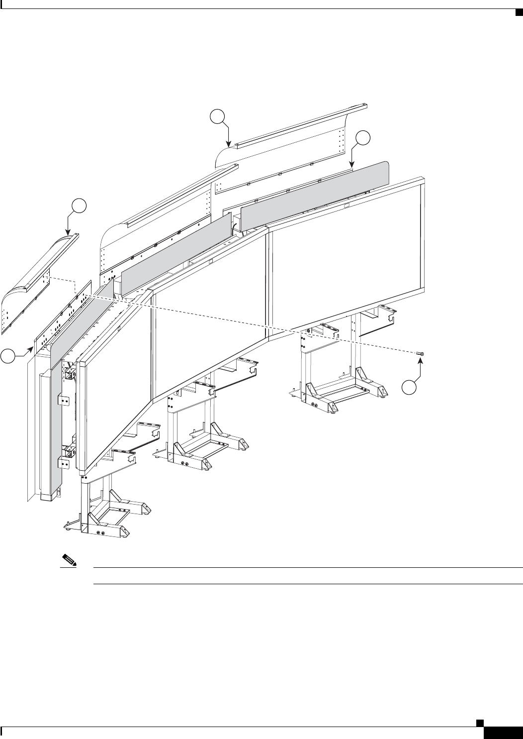
Cisco TelePresence System 3200
OL-14521-01
Chapter 4 Building the Lighting Assembly
Parts List
Step 20 Join the left, center, and right Reflector tops with the left and right Reflector Transition pieces.
Figure 4-20 Left and Right Reflector Transition pieces
Note Do not tighten screws until completing Step 22.
201143
21
28
20
27
18
17
4-23
Cisco TelePresence System 3200
OL-14521-01
Chapter 4 Building the Lighting Assembly
Parts List
Step 21 Attach the left and right (vertical) Reflector ends to the left and right (vertical) Reflector Bottom ends.
Figure 4-21 Left and Right (vertical) Reflector ends
Note Do not tighten screws until completing Step 22.
201144
15
27
19
33 27
19
4-24
Cisco TelePresence System 3200
OL-14521-01
Chapter 4 Building the Lighting Assembly
Parts List
Step 22 Attach the left and right corner Reflector Transition pieces to the Reflector tops.
Figure 4-22 Left and Right corner Reflector Transition pieces
Note Tighten all screws from Figure 4-18 through Figure 4-22. The goal is to ensure the reflector pieces form
a “seamless hood” around the lighting assembly.
22
18
18
22
201145
28
27
4-25
Cisco TelePresence System 3200
OL-14521-01
Chapter 4 Building the Lighting Assembly
Parts List
Step 23 Attach the two Metal Trim panels to the L-brackets attached to the two (vertical) Plastic Diffuser panels.
Figure 4-23 Two Metal Trim panels
Note Install the codecs before you continue to the next chapter. See Step 5 through Step 8 in Chapter 8,
“Assembling the Remaining Cisco TelePresence Elements” to install the codecs; then see Chapter 5,
“Building the Display Shelf Assembly” to continue the installation.
Note These Metal Trim panels cover the access opening used to route cables. You may not want to attach these
Metal Trim panels until you complete the cable routing in Chapter 9, “Routing Power and Signal
Cables.”
201146
11
5
27
11

4-26
Cisco TelePresence System 3200
OL-14521-01
Chapter 4 Building the Lighting Assembly
Parts List
Tip If required, use the white touch-up paint on the light reflectors to fix any minor cosmetic issues caused
by assembly, shipping, or handling.

CHAPTER
6-1
Cisco TelePresence System 3200
OL-14521-01
6
Building the First Row Table Assembly
Revised: July 28, 2008, OL-14521-01
Parts List
Key Part Description Part Number Qty Ctn Notes
1Tabletop leg base 800-28454-xx
800-28628-xx (left)
3
1
52-
54
52
2Metal packaging brace 700-24275-xx 441-
43,
57
3Molded foam bumper 800-28625-xx 441-
43,
57
4Tabletop section: right wing 95-9690-xx
Kit # 74-5302-xx
158
5Tabletop section: Center right 95-9687-xx
Kit # 74-5300-xx
1 58
6Tabletop section: center 95-9686-xx
Kit # 74-5299-xx
158
7Tabletop section: Center left 95-9689-xx
Kit # 74-5301-xx
158
8Tabletop section: left door 95-9691-xx
Kit # 74-5303-xx
158
9Connecting plate 700-27292-xx 650
10 Draw bolt No part number 12 1
11 Left tabletop hinge 51-4539-xx 1 1
12 Spline No part number 5 1
13 “Please close” label 56-15736-xx 1
14 M8 x 16 mm screws, black 48-2430-xx 30 1

6-2
Cisco TelePresence System 3200
OL-14521-01
Chapter 6 Building the First Row Table Assembly
Parts List
Caution The table segments are unstable during assembly. Use caution, and support all structures as required.
Warning
Only trained and qualified personnel should be allowed to install, replace, or service this equipment.
Caution Table elements are heavy, and metal edges can be very sharp. Protect your hands and eyes from injury
by wearing safety gloves and glasses.
Caution In order to prevent scratching the Display shelves, you should avoid putting any tools on the shelf
surfaces.
15 M4 x 12 mm flathead screws 48-1641-xx 1
16 Phillips head wood screws 8 1 Included with Left tabletop hinge.
17 Plate for left side table Part number to be
provided
1Installs on the side closest to the table
door.
18 I/O blank: large 700-23806-xx 1
19 I/O blank: small 700-23807-xx 6 1
20 I/O modules: power/Ethernet 74-xxxx-xx 6 1 Part number changes per country. Refer
to “Appendix B: Region- and
Country-Specific Equipment” for part
number.
21 I/O Module Cover plate 700-23305-xx 50-
54
22 10 m Cat6 Ethernet cable 37-0901-xx 6 1
23 3 m Jumper cord 37-0833-xx 9 1
24 M4 nuts 49-0326 20 1
25 M4 x 12 mm screws, black 48-2426-xx
Kit # 69-1878-xx
10 1
26 Microphone 74-4743-xx 3 1
27 M4 x 30 mm screws 1Included in Microphone kit.
28 M4 washers 1Included in Microphone kit.
29 Table hinge safety hinge To be provided 1
Privacy Panel Assembly
1Privacy panel: Center left 700-23333-xx 134
2Privacy panel: center 700-23334-xx 134
3Privacy panel: Center right 700-23332-xx 134
4Privacy panel: right wing 700-23362-xx 114
5M8 x 20 mm screws 48-2273-xx 1
Key Part Description Part Number Qty Ctn Notes
6-3
Cisco TelePresence System 3200
OL-14521-01
Chapter 6 Building the First Row Table Assembly
Parts List
Note The directions left and right refer to the assembly as you face it from the front.
Warning
Table legs are unstable until they are fully attached to the tabletop. Do not use unattached table legs
as tabletop supports while you attach tabletop segments. They can fall and cause injury or damage.
Cisco suggests you use the accessory cabinets to support and stabilize the table segments as you
install them.
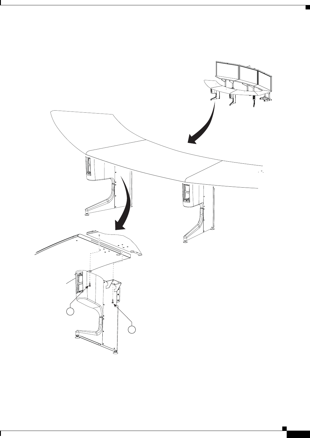
Step 1 Remove the Metal packaging braces from the Molded foam bumpers.
Figure 6-1 Metal packaging braces and their Molded foam bumpers
201152
3
2

6-4
Cisco TelePresence System 3200
OL-14521-01
Chapter 6 Building the First Row Table Assembly
Parts List
Step 2 Assemble the four Molded foam bumpers and the four Table leg bases.
Figure 6-2 Four Molded foam bumpers and the four Table leg bases
Note The leg base with only one top right attachment bracket is the left most table leg (see
Figure 6-12). The other three legs each have two attachment brackets.
6-5
Cisco TelePresence System 3200
OL-14521-01
Chapter 6 Building the First Row Table Assembly
Parts List
Step 3 Assemble the I/O modules for the outside left and outside right molded foam bumpers.
The outside left and outside right molded foam bumpers only have one I/O module each. The inner
molded foam bumpers have two (see Figure 6-4).
Figure 6-3 Foam Bumper Assembly
Note Steps for routing the Ethernet and power cables are in Chapter 9, “Routing Power and Signal Cables.”
Note The flange on the I/O module cover place is wider on the bottom than on the top.
204176
18
21
19
20
25
22 23 24
6-6
Cisco TelePresence System 3200
OL-14521-01
Chapter 6 Building the First Row Table Assembly
Parts List
Step 4 Assemble the I/O modules for the inner molded foam bumpers.
Figure 6-4 Foam Bumper Assembly
Note Steps for routing the Ethernet and power cables are in Chapter 9, “Routing Power and Signal Cables.”
Note The flange on the I/O module cover place is wider on the bottom than on the top.
204178
21
20
19
25
22 23 24
6-7
Cisco TelePresence System 3200
OL-14521-01
Chapter 6 Building the First Row Table Assembly
Parts List
Step 5 Attach the right wing tabletop section to the right Accessory Cabinet bracket.
Figure 6-5 Right Wing Tabletop Section
201154
15
4
6-8
Cisco TelePresence System 3200
OL-14521-01
Chapter 6 Building the First Row Table Assembly
Parts List
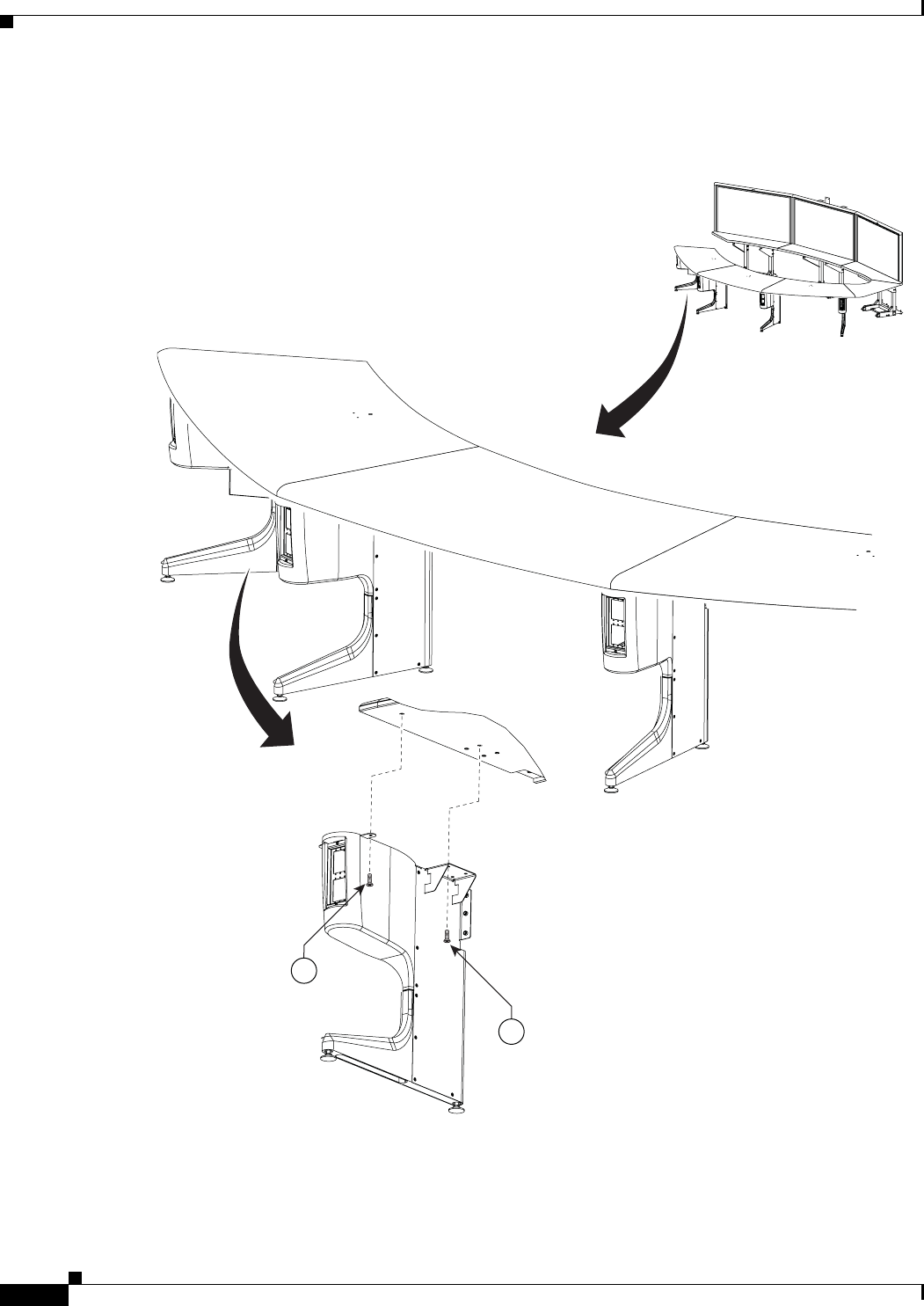
Step 6 Attach the right Table segment.
a. Make sure you tighten the draw bolt evenly on both sides.
b. While a draw bolt is being tightened, hold the table edges together to avoid damage to the draw bolt
or the table segment.
c. Tighten the draw bolt so the two table segments are connected snugly.
d. While one person is tightening the draw bolt from below, it is important for the support person to
maintain the alignment of the table segment edges.
Figure 6-6 Right Table segment
Note The splines have different lengths. Use a spline that is slightly smaller than the slot in the table top.
5
12
4
204138
10
30
9
6-9
Cisco TelePresence System 3200
OL-14521-01
Chapter 6 Building the First Row Table Assembly
Parts List
Step 7 Attach the right most Table Leg.
Figure 6-7 right Most Table Leg
15
15
204140
6-10
Cisco TelePresence System 3200
OL-14521-01
Chapter 6 Building the First Row Table Assembly
Parts List
Step 8 Attach the center Table segment.
a. Make sure you tighten the draw bolt evenly on both sides.
b. While a draw bolt is being tightened, hold the table edges together to avoid damage to the draw bolt
or the table segment.
c. Tighten the draw bolts so the two table segments are connected snugly.
d. While one person is tightening the draw bolt from below, it is important for the support person to
maintain the alignment of the table segment edges.
Figure 6-8 Center Table segment
Note The splines have different lengths. Use a spline that is slightly smaller than the slot in the table top.
65
12
204139
10
6-11
Cisco TelePresence System 3200
OL-14521-01
Chapter 6 Building the First Row Table Assembly
Parts List
Step 9 Attach the right center Table leg.
Figure 6-9 right center Table leg
15
15
204141
6-12
Cisco TelePresence System 3200
OL-14521-01
Chapter 6 Building the First Row Table Assembly
Parts List
Step 10 Attach the left Table segment.
a. The draw bolts have two halves that screw into a center piece.
b. While a draw bolt is being tightened, hold the table edges together to avoid damage to the draw bolt
or the table segment.
c. Tighten the draw bolts so the two table segments are connected snugly.
d. While one person is tightening the draw bolts from below, it is important for the support person to
maintain the alignment of the table segment edges.
Figure 6-10 Left Table segment
Note The splines have different lengths. Use a spline that is slightly smaller than the slot in the table top.
204142
7
6
12
10
6-13
Cisco TelePresence System 3200
OL-14521-01
Chapter 6 Building the First Row Table Assembly
Parts List
Step 11 Attach the left center Table leg.
Figure 6-11 Left center Table leg
15
15
204143
6-14
Cisco TelePresence System 3200
OL-14521-01
Chapter 6 Building the First Row Table Assembly
Parts List
Step 12 Attach the left most Table leg.
Figure 6-12 left Most Table Leg
15
15
204144
6-15
Cisco TelePresence System 3200
OL-14521-01
Chapter 6 Building the First Row Table Assembly
Parts List
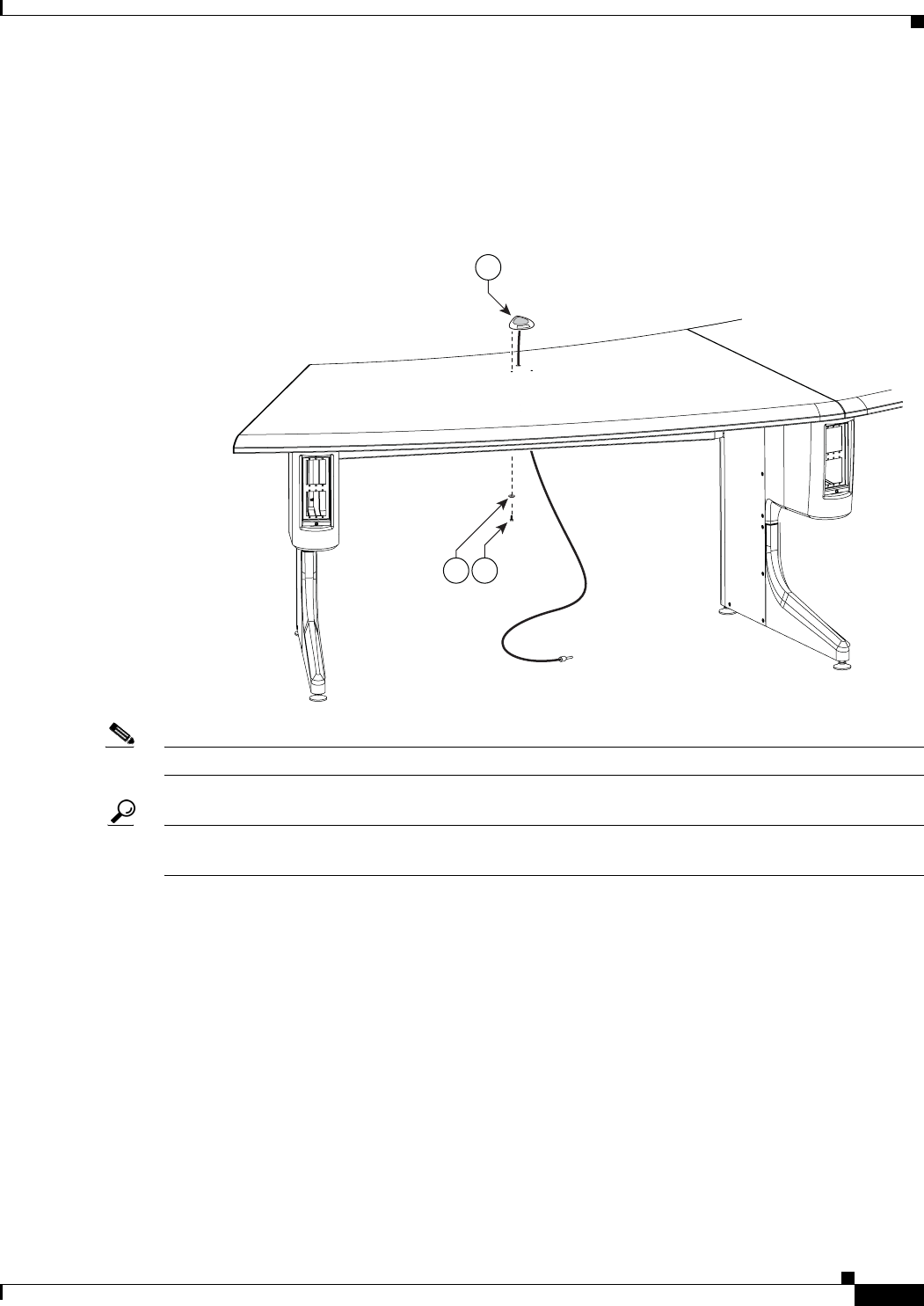
Step 13 Attach one microphone to each table segment. There are three microphones for the first row table.
The center microphone cable for the first row table must be seated in the cable channel on the underside
of the center table segment in order to properly install the projector mounting bracket. You can use tape
to secure it in place.
Figure 6-13 Microphone Assembly
Note Steps for routing the microphone cables are in Chapter 9, “Routing Power and Signal Cables.”
Tip Label each microphone cable where it exits from the table. You attach the microphones to the
Audio/Video Expansion Unit in Chapter 9, “Routing Power and Signal Cables.”
204177
2728
26
6-16
Cisco TelePresence System 3200
OL-14521-01
Chapter 6 Building the First Row Table Assembly
Parts List
Step 14 Attach the table door to the tabletop sections and attach the “please close” label to the underside of the
table door.
Figure 6-14 Left connecting Tabletop section
204145
11
15
29
16
3017
6-17
Cisco TelePresence System 3200
OL-14521-01
Chapter 6 Building the First Row Table Assembly
Parts List
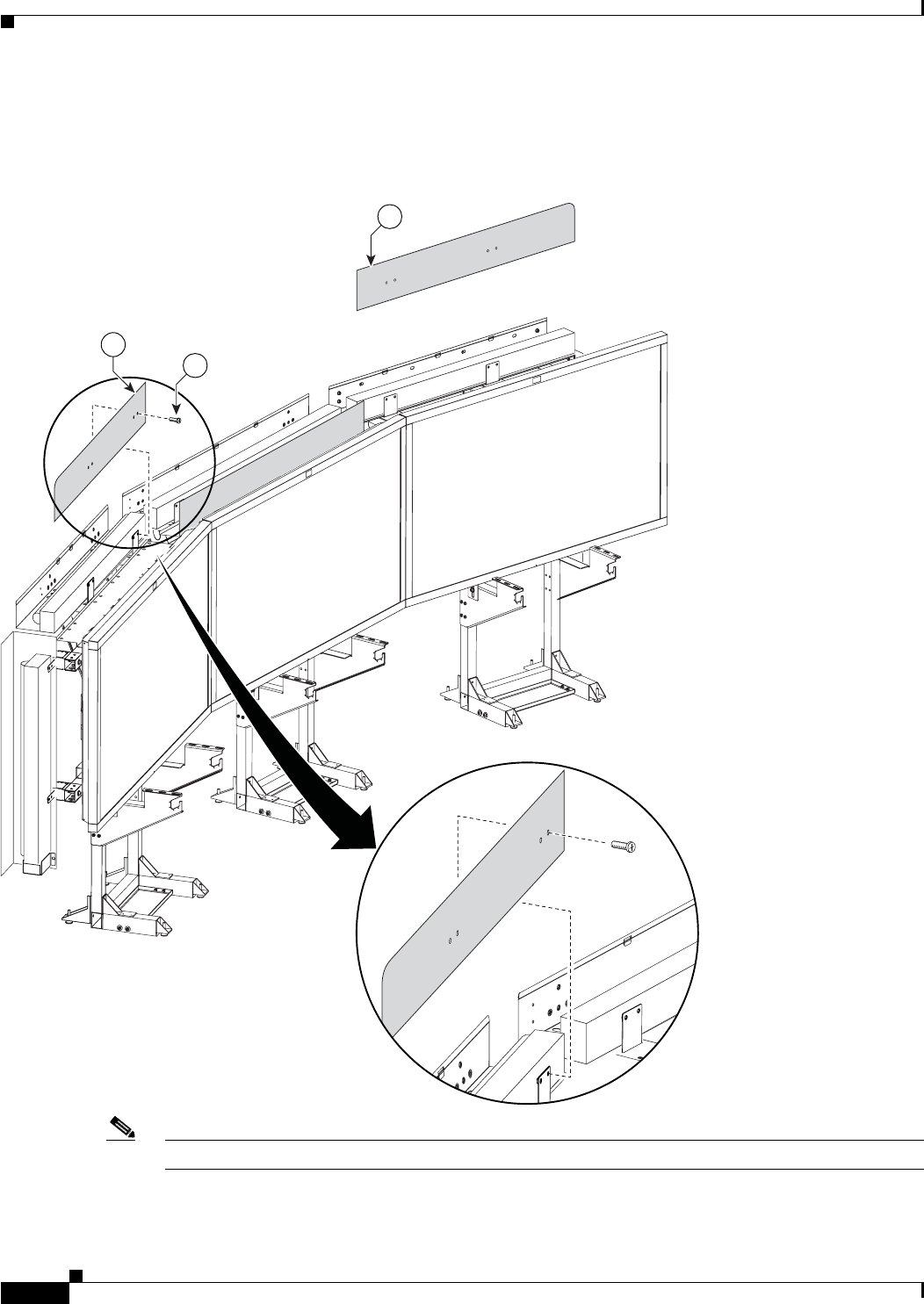
Step 15 Attach the center Privacy panel.
Figure 6-15 Privacy Panel Assembly
2
5
Rotated
for clarity
201171
6-18
Cisco TelePresence System 3200
OL-14521-01
Chapter 6 Building the First Row Table Assembly
Parts List
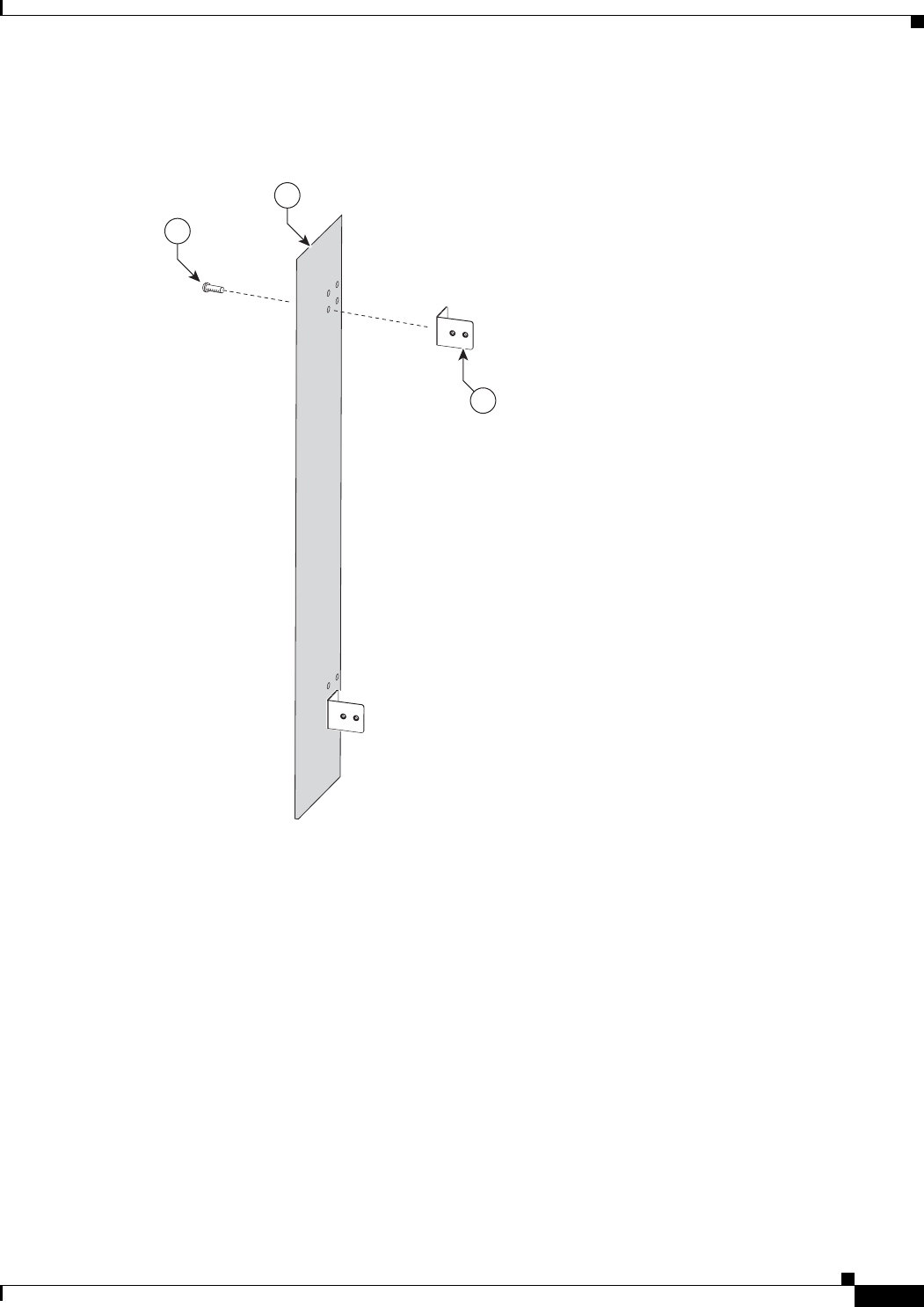
Step 16 Attach the left Privacy panel.
Figure 6-16 Privacy Panel Assembly
15
201172
Rotated
for clarity
6-19
Cisco TelePresence System 3200
OL-14521-01
Chapter 6 Building the First Row Table Assembly
Parts List
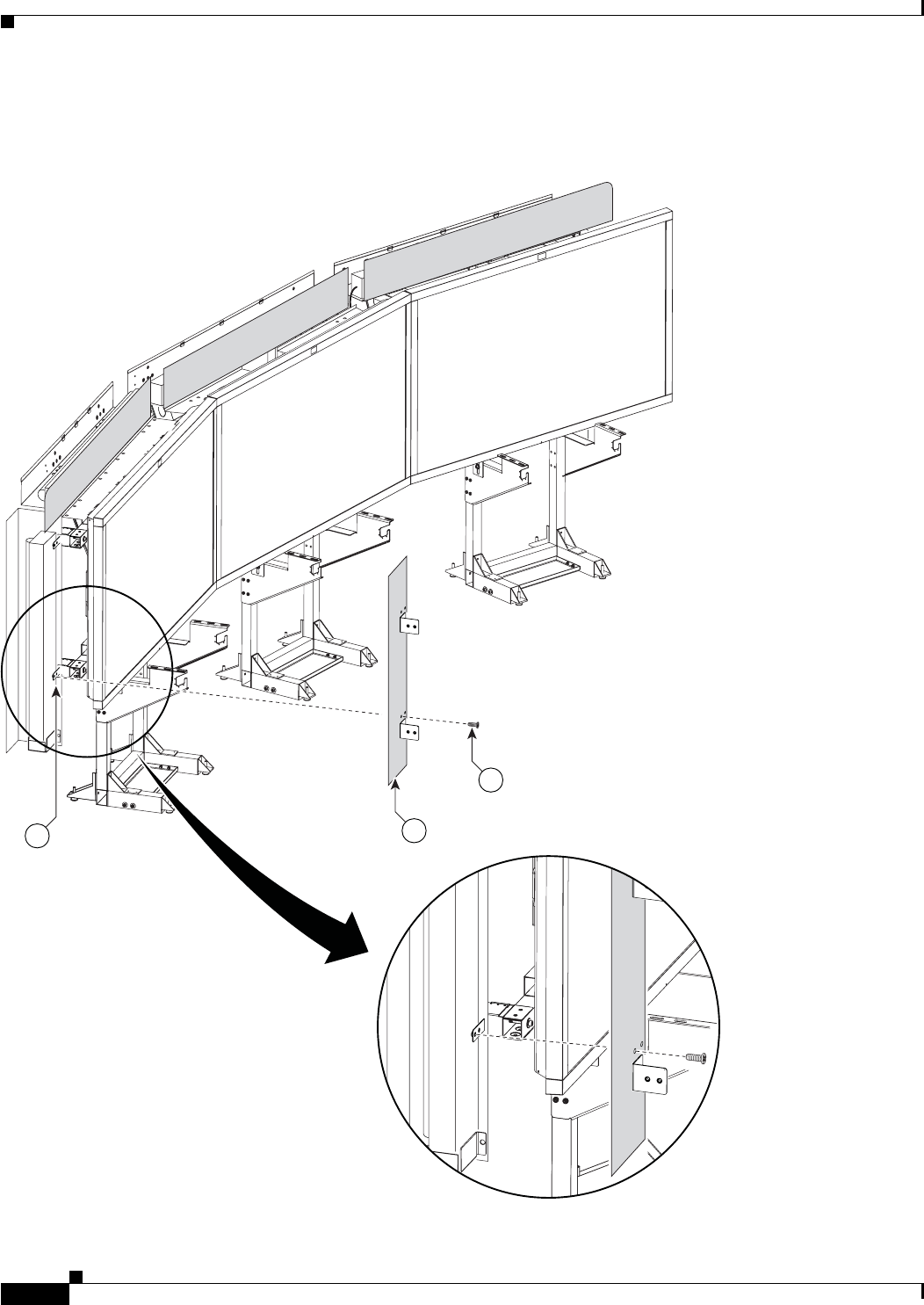
Step 17 Attach the right Privacy panel.
Figure 6-17 Privacy Panel Assembly
3
5
201173
Rotated
for clarity
6-20
Cisco TelePresence System 3200
OL-14521-01
Chapter 6 Building the First Row Table Assembly
Parts List
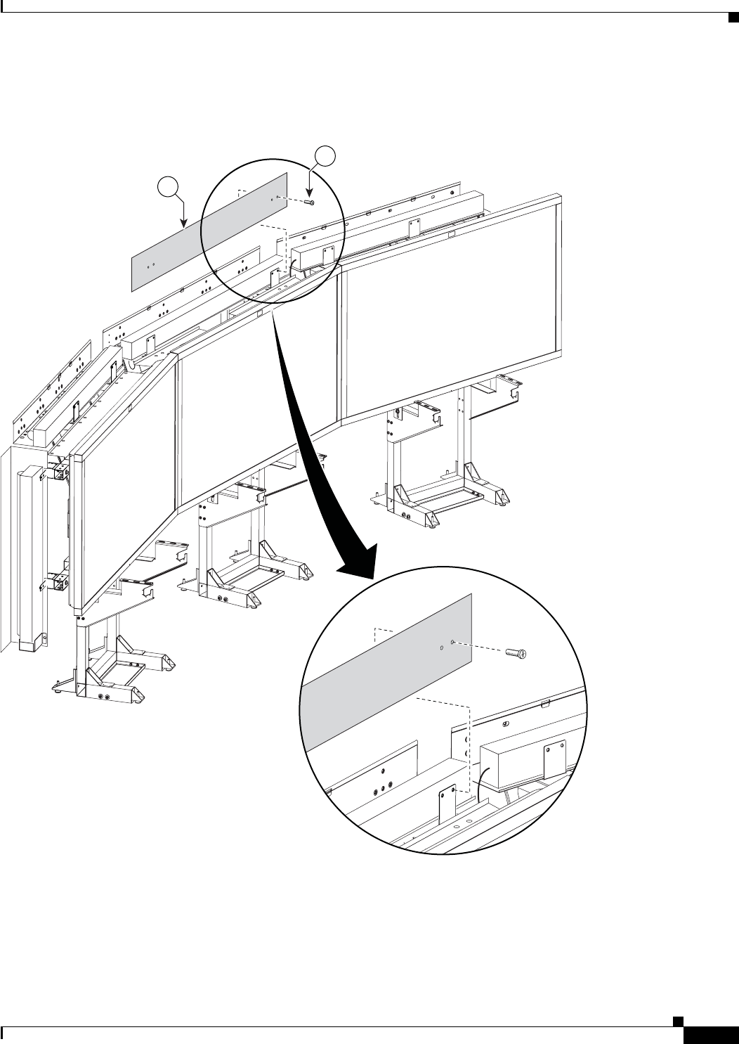
Step 18 Attach the right wing Privacy panel.
Figure 6-18 Privacy Panel Assembly
45
201174

CHAPTER
7-1
Cisco TelePresence System 3200
OL-14521-01
7
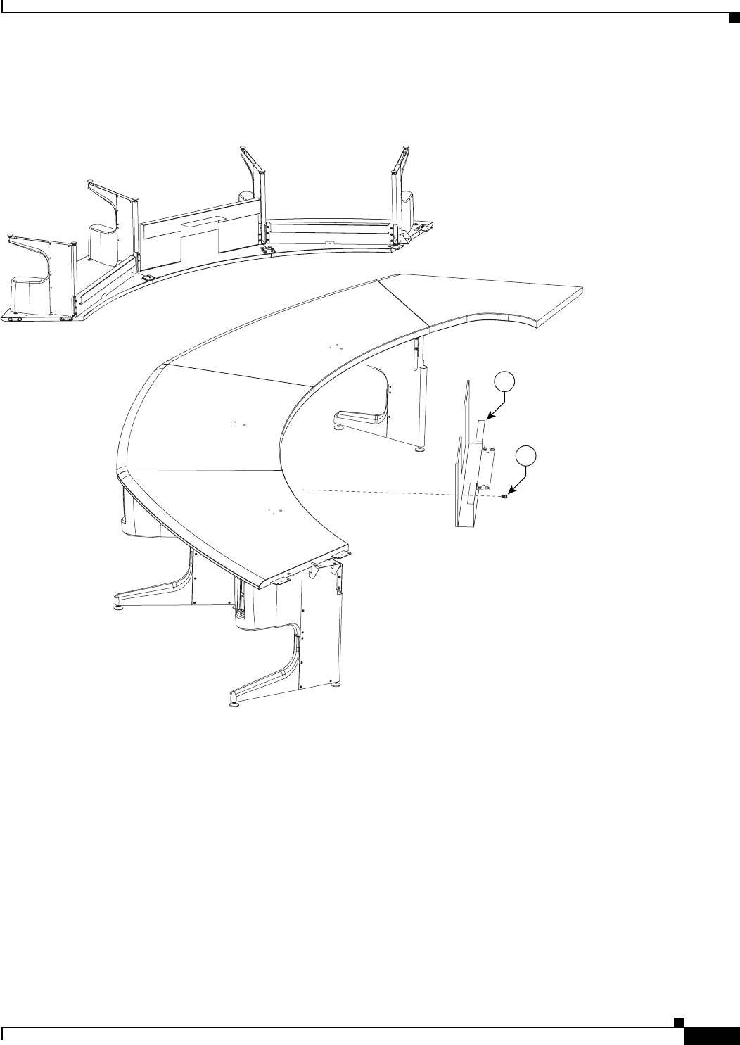
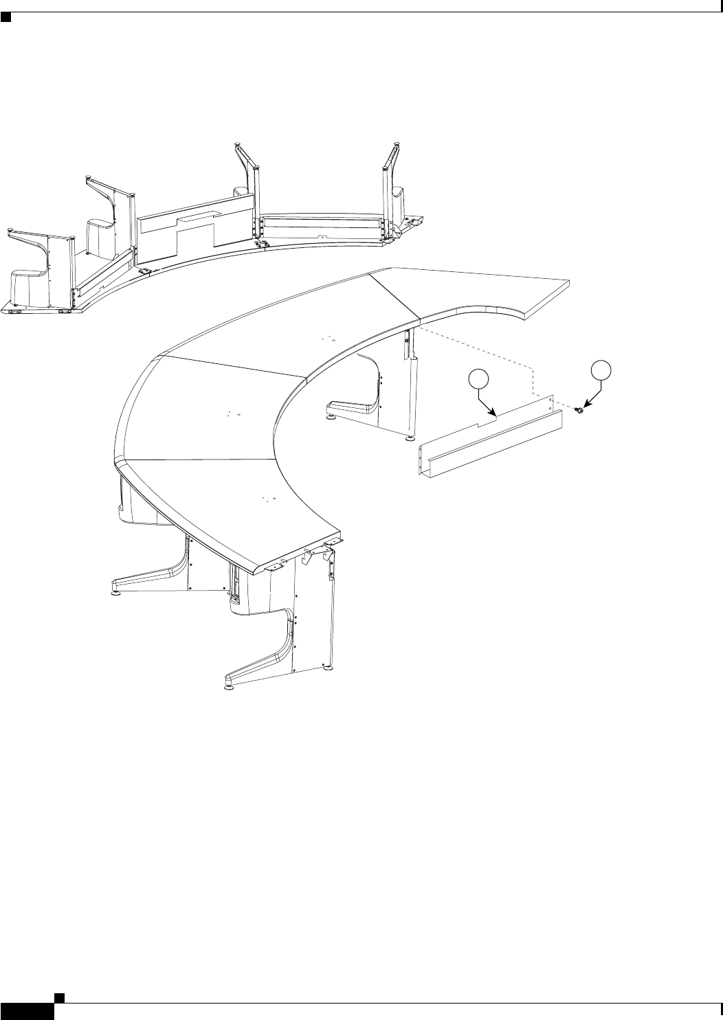
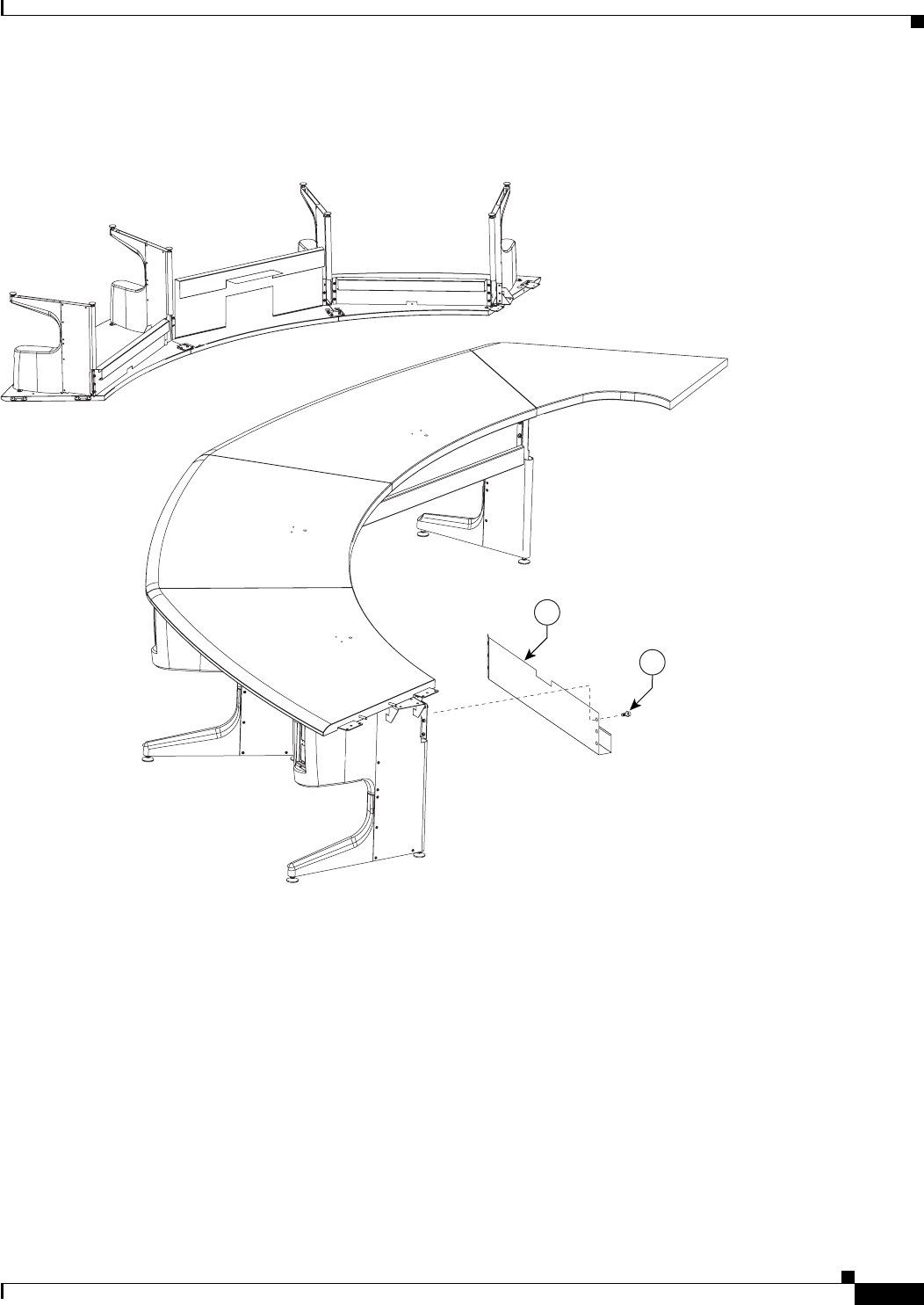
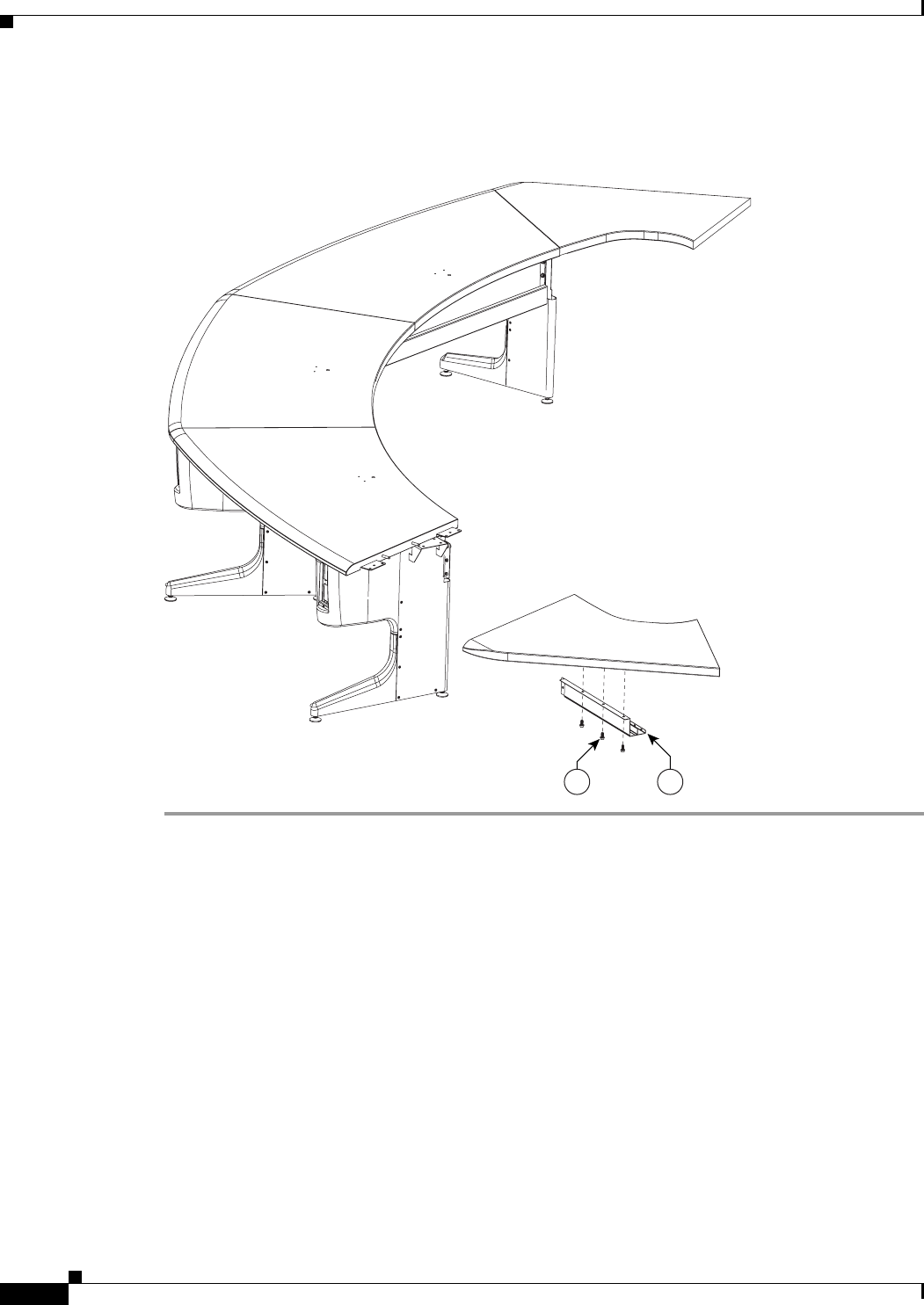
Building the Second Row Table Assembly
Revised: July 28, 2008, OL-14521-01
Parts List
Key Part Description Part Number Qty Ctn Notes
1Tabletop leg base 800-28454-xx 752-
54
2Metal packaging brace 700-24275-xx 741-
43,
57
3Molded foam bumper 800-28625-xx 741-
43,
57
4Gutter and privacy panel support bracket,
type 1
700-27280-xx 250
5Gutter and privacy panel support bracket,
type 2
700-27279-xx 550
6Gutter panel, section 1 800-31126-xx 150
7Gutter panel, section 2 800-31129-xx 150
8Gutter panel, section 3 800-31131-xx 150
9Gutter panel, section 4 800-31133-xx 150
10 Gutter panel, section 5 800-31124-xx 250
11 Privacy panel hanger 700-27311-xx 14 50
12 Floating bracket, type 1 700-27282-xx 250
13 Floating bracket, type 2 700-27281-xx 250
14 Tabletop: section 1 95-9995-01
Kit # 74-5565-01
126
15 Tabletop: section 2 95-10096-01
Kit # 74-5600-01
126

7-2
Cisco TelePresence System 3200
OL-14521-01
Chapter 7 Building the Second Row Table Assembly
Parts List
16 Tabletop: section 3 95-10097-01
Kit # 74-5601-01
126
17 Tabletop: section 4 95-10098-01
Kit # 74-5602-01
126
18 Tabletop: section 5 95-9994-01
Kit # 74-5562
226
19 Tabletop end, left (section 6) 95-10099-01
Kit # 74-5603-01
126
20 Tabletop end, right (section 7) 95-10100-01
Kit # 74-5604
126
21 Tabletop end brace 700-27413-xx 250
22 Privacy panel alignment bracket,
section 1
700-27275-xx 150
23 Privacy panel alignment bracket,
section 2
700-27276-xx 150
24 Privacy panel alignment bracket,
section 3
700-27277-xx 150
25 Privacy panel alignment bracket,
section 4
700-27278-xx 150
26 Privacy panel alignment bracket,
section 5
700-27274-xx 250
27 Privacy panel, section 1 800-31112-xx 150
28 Privacy panel, section 2 800-31116-xx 150
29 Privacy panel, section 3 800-31117-xx 150
30 Privacy panel, section 4 800-31119-xx 150
31 Privacy panel, section 5 800-31121-xx 250
32 Privacy Panel, left end (section 6) 800-31123-xx 150
33 Privacy Panel, right end (section 7) 800-31122-xx 150
34 Tabletop attachment plate, metal 700-27292-xx 250
35 M8 x 16 mm screws, black 69-1879-01
48-2430-01
58 21
36 M8 x 2.5mm shoulder screws 69-1880-01
48-2437-01
30 21
37 M4 x 12 mm pan head screws 69-1878-01
48-2426-01
24 21
38 Screw, 8 x 50 mm, with plastic knob 69-1877-01
48-2298-01
15 21
39 Draw bolt No part number 14 1
40 Spline No part number 5 1
41 Cable Cover for right end privacy panel 700-27312-01 150
42 Velcro attachments for cable guide No part number 2Included with cable cover
Key Part Description Part Number Qty Ctn Notes

7-3
Cisco TelePresence System 3200
OL-14521-01
Chapter 7 Building the Second Row Table Assembly
Parts List
Caution The table segments are unstable during assembly. Use caution, and support all structures as required.
Warning
Only trained and qualified personnel should be allowed to install, replace, or service this equipment.
Caution Table elements are heavy, and metal edges can be very sharp. Protect your hands and eyes from injury
by wearing safety gloves and glasses.
43 I/O blank: large 69-1830-01 2 1
44 I/O blank: small 700-23807-01 14 1
45 I/O modules: power/Ethernet 74-xxxx-xx 12 1Part number changes per country. Refer
to “Appendix B: Region- and
Country-Specific Equipment” for part
number.
46 I/O Module Cover plate 700-23305-01 750-
54
47 Cat6 Ethernet cord 37-0887-02 (3M)
37-0901-01 (10M)
37-0965-01 (12M)
1
8
3
1
48 3 m Jumper cord 37-0833-01 9 1
49 M4 nuts 49-0326 20 1
50 M4 x 12 mm screws, black 48-2426-01 10 1
51 Microphone 74-4743-01 6 1
52 M4 x 30 mm screws 1Included in Microphone kit.
53 M4 washers 1Included in Microphone kit.
54 Power distribution units 74-4787-01 2 1 Chapter 7, 8
55 Screws To be provide d 1 1
56 M8 shoulder screws for Floating
Brackets
69-1880-01
48-2437-01
28 21
Microphone extension cords, 9.5M 37-0931-01 6 1 Attach these cords to the microphone
cables to reach the audio/video extension
unit.
Touch-up paint, dark gray 79-2269-01 1 1 Use this to cover any imperfections for
the privacy panel that are caused by
assembly, shipping or handling.
Touch-up paint, dark gray 95-10160-01 1 1 Use this to cover any imperfections for
the privacy panel that are caused by
assembly, shipping or handling.
Key Part Description Part Number Qty Ctn Notes
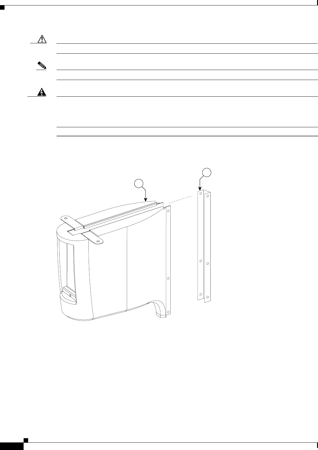
7-4
Cisco TelePresence System 3200
OL-14521-01
Chapter 7 Building the Second Row Table Assembly
Parts List
Caution In order to prevent scratching the table tops, you should avoid putting any tools on the shelf surfaces.
Note The directions left and right refer to the assembly as you face it from the front.
Warning
Table legs are unstable until they are fully attached to the tabletop. Do not use unattached table legs
as tabletop supports while you attach tabletop segments. They can fall and cause injury or damage.
Cisco suggests you use the accessory cabinets to support and stabilize the table segments as you
install them.
Step 1 Remove the Metal packaging braces from the Molded foam bumpers.
Figure 7-1 Metal packaging braces and their Molded foam bumpers
201152
3
2
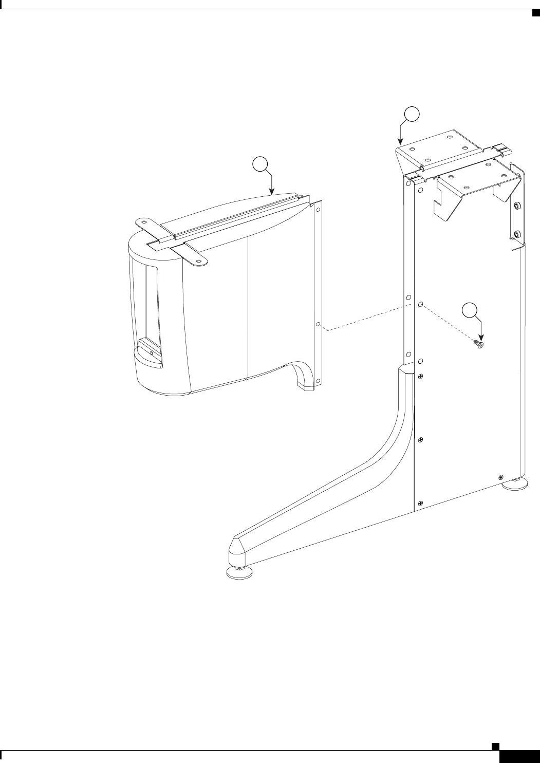
7-5
Cisco TelePresence System 3200
OL-14521-01
Chapter 7 Building the Second Row Table Assembly
Parts List
Step 2 Assemble the seven Molded foam bumpers and the seven Table leg bases.
Figure 7-2 Four Molded foam bumpers and the four Table leg bases
204149
3
37
1
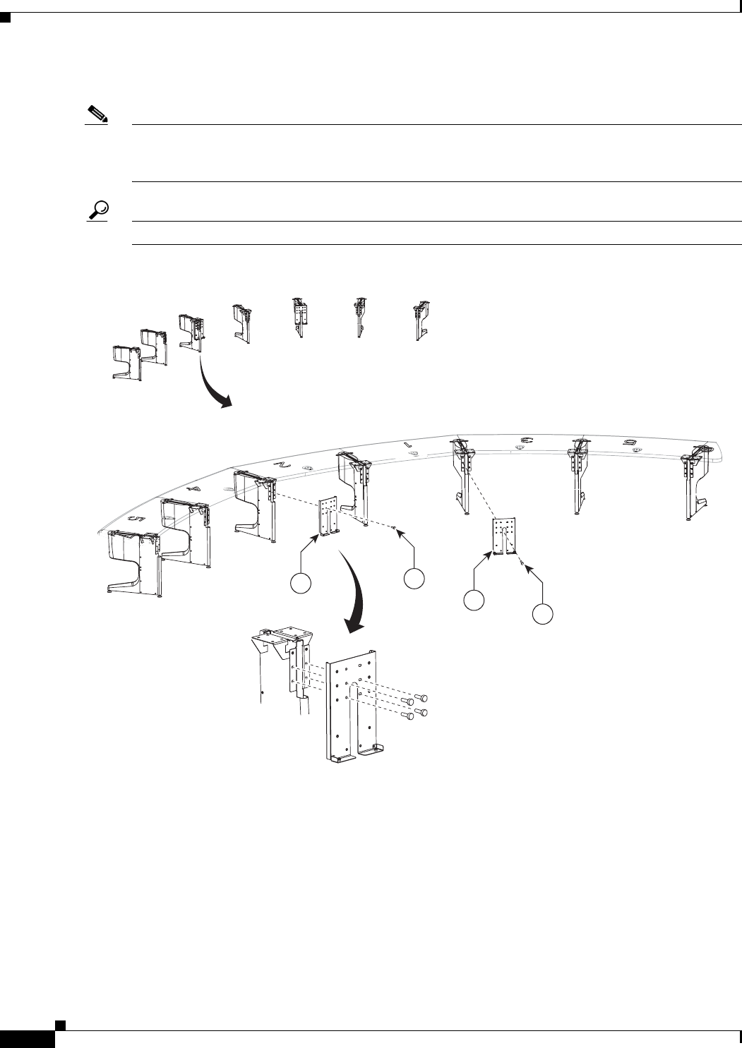
7-6
Cisco TelePresence System 3200
OL-14521-01
Chapter 7 Building the Second Row Table Assembly
Parts List
Step 3 Attach the first set of support brackets for the gutter and privacy panel to the table legs.
Note Note the table layout. Each section is numbered as shown in Figure 7-3. Each cable gutter and privacy
panel is different. The numbering for the cable gutters and privacy panels correspond to the numbering
for the table top.
Tip When you attach the support brackets, it can be helpful to turn the table leg upside-down.
Figure 7-3 Gutter and Privacy Panel Support Brackets, Type 1
4
4
35
35
204101
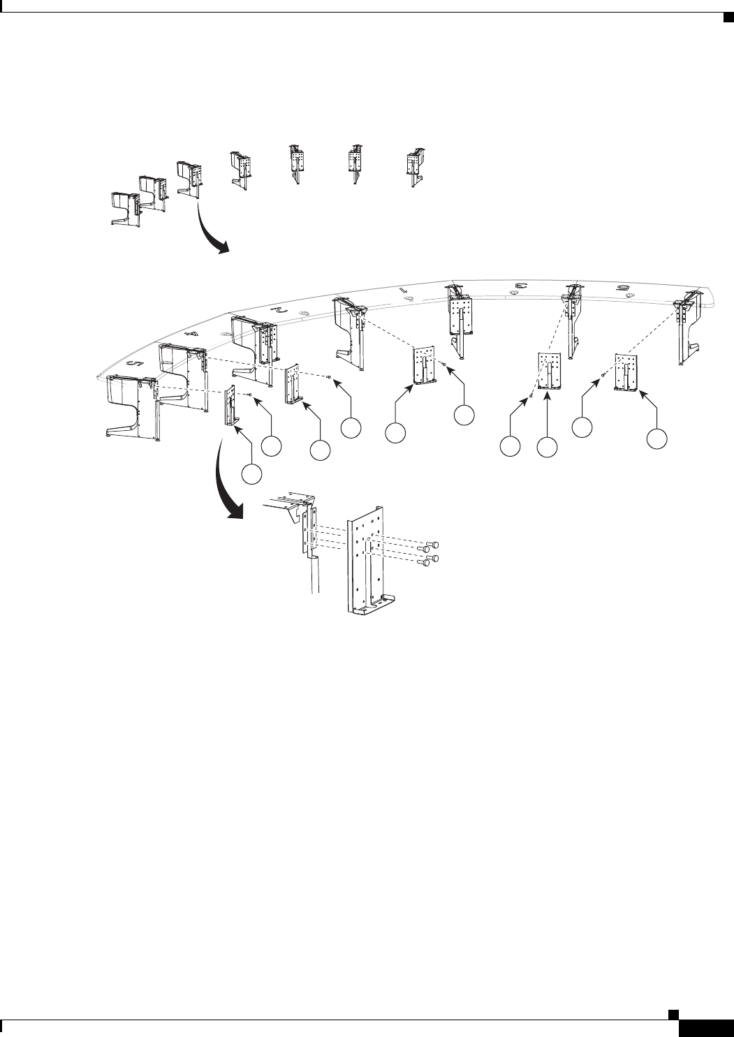
7-7
Cisco TelePresence System 3200
OL-14521-01
Chapter 7 Building the Second Row Table Assembly
Parts List
Step 4 Attach the second set of five support brackets to the table legs.
Figure 7-4 Gutter and Privacy Panel Support Brackets, Type 2
35
5
5
204102
5
35
35
35
355
5
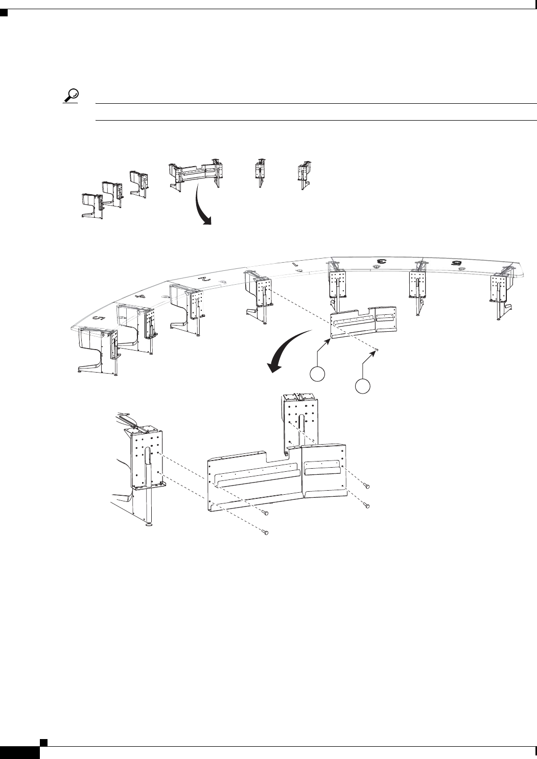
7-8
Cisco TelePresence System 3200
OL-14521-01
Chapter 7 Building the Second Row Table Assembly
Parts List
Step 5 While one or more assistants keep the table legs steady, attach the Section 1 gutter panel to the Section
1 table legs.
Tip When you attach the support brackets, it can be helpful to turn the table leg upside-down.
Figure 7-5 Section 1 Gutter Panel
204103
6
35
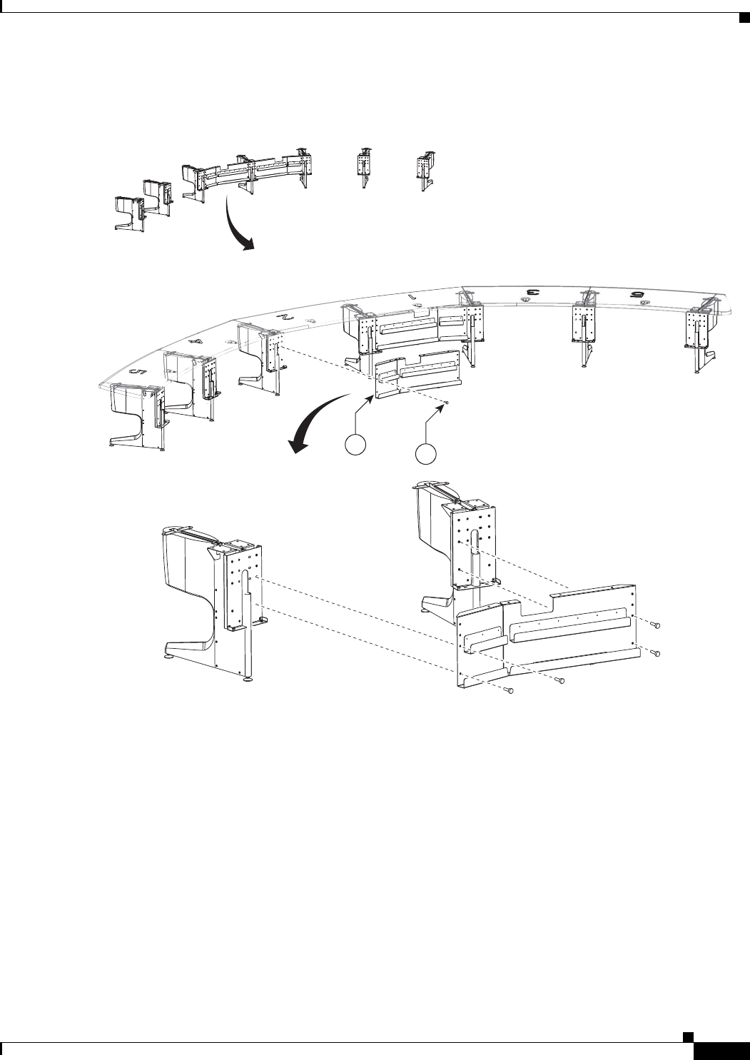
7-9
Cisco TelePresence System 3200
OL-14521-01
Chapter 7 Building the Second Row Table Assembly
Parts List
Step 6 Attach the Section 2 gutter panel to the Section 2 table legs.
Figure 7-6 Section 2 Gutter Panel
204104
735
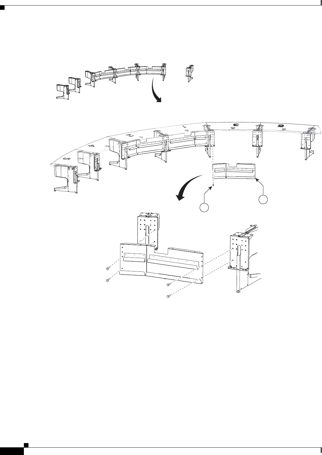
7-10
Cisco TelePresence System 3200
OL-14521-01
Chapter 7 Building the Second Row Table Assembly
Parts List
Step 7 Attach the Section 3 gutter panel to the Section 3 table legs.
Figure 7-7 Section 3 Gutter Panel
204105
35
8
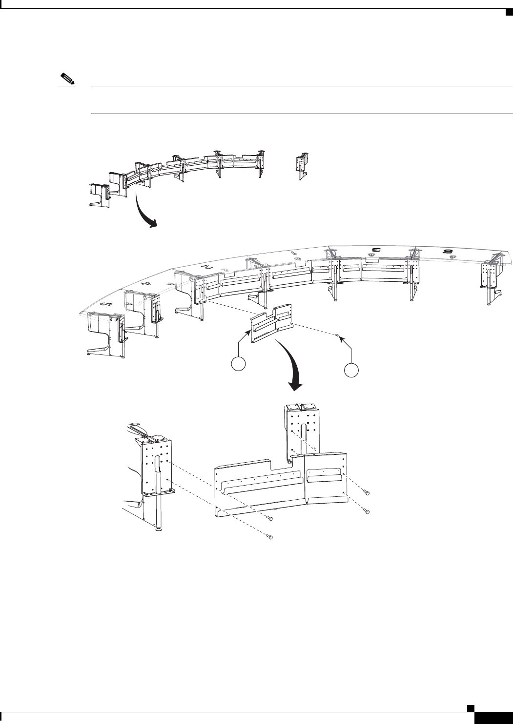
7-11
Cisco TelePresence System 3200
OL-14521-01
Chapter 7 Building the Second Row Table Assembly
Parts List
Step 8 Attach the Section 4 gutter panel to the Section 4 table legs.
Note If you are building a Reduced Configuration table (four tabletops instead of six), continue to Step 11
after completing this step.
Figure 7-8 Section 4 Gutter Panel
204106
935
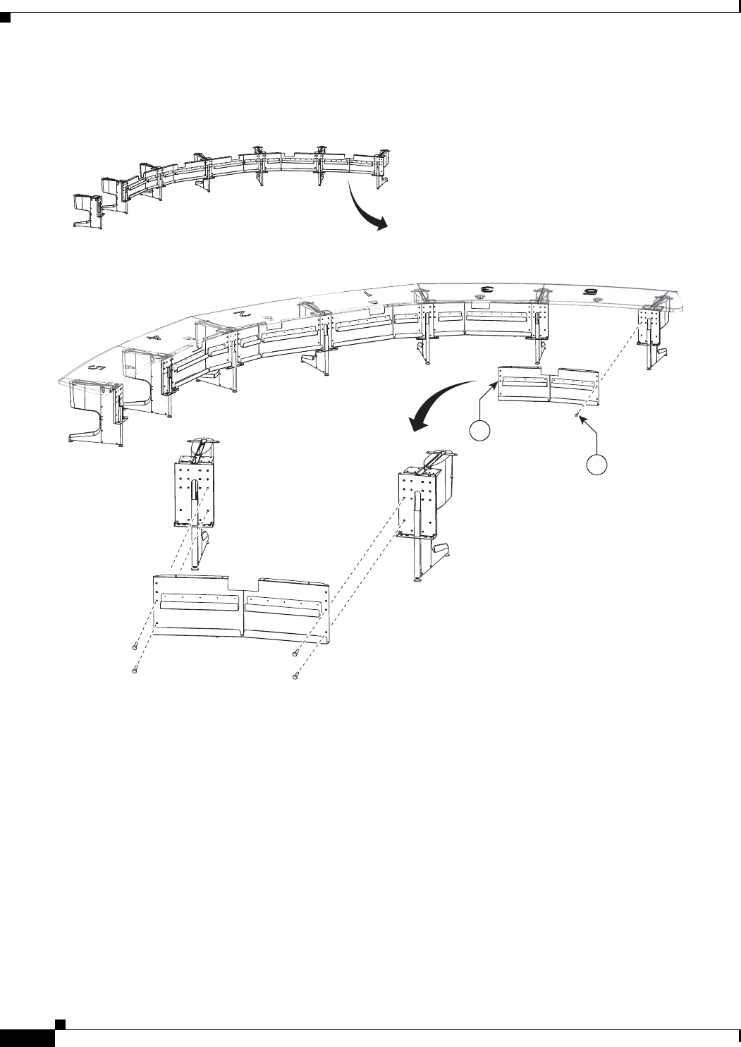
7-12
Cisco TelePresence System 3200
OL-14521-01
Chapter 7 Building the Second Row Table Assembly
Parts List
Step 9 Attach the left Section 5 gutter panels to the remaining table legs.
Figure 7-9 Section 5 (Left) Gutter Panels
204107
10
35
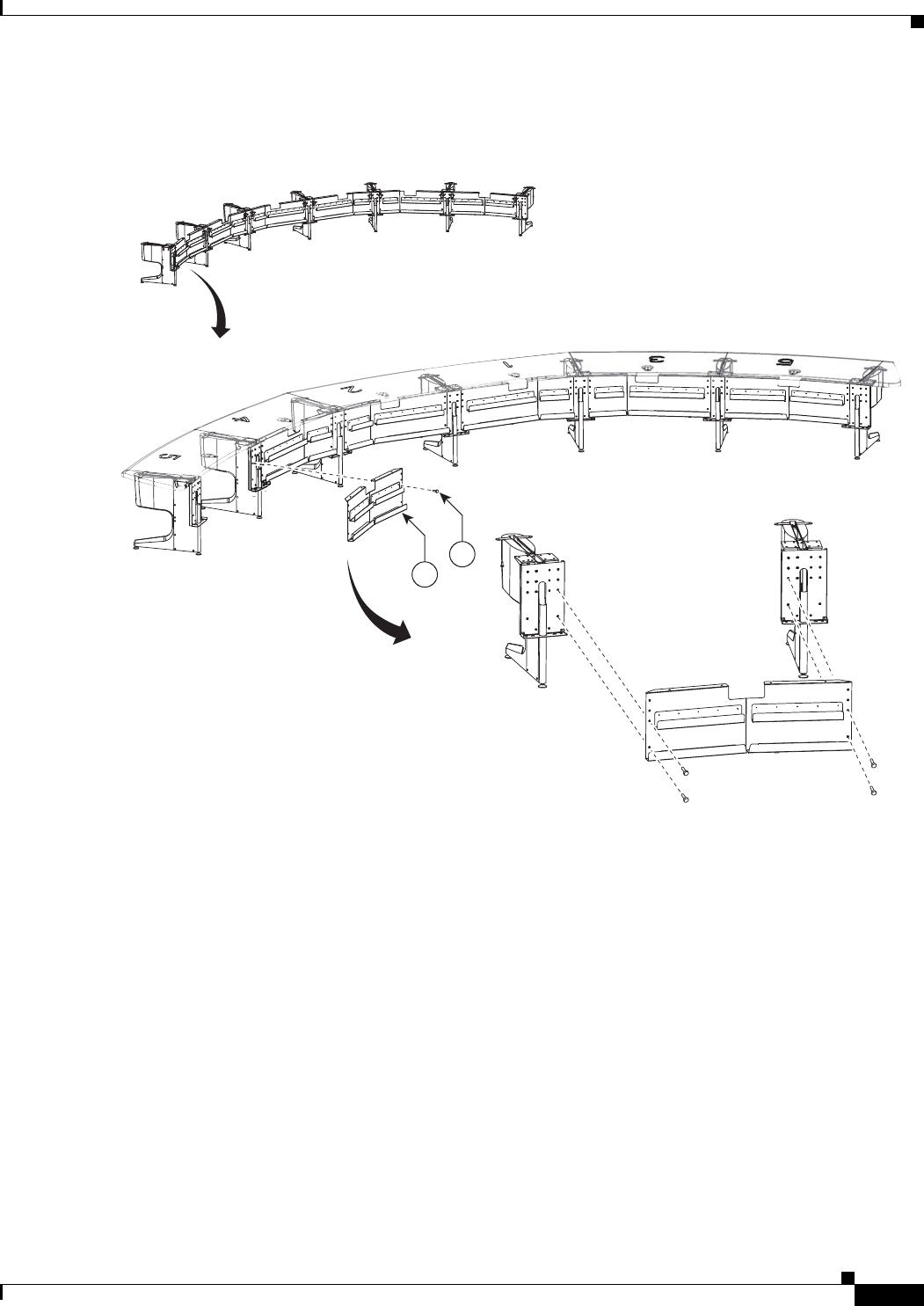
7-13
Cisco TelePresence System 3200
OL-14521-01
Chapter 7 Building the Second Row Table Assembly
Parts List
Step 10 Attach the right Section 5 gutter panels to the remaining table legs.
Figure 7-10 Section 5 (Right) Gutter Panels
204108
35
10
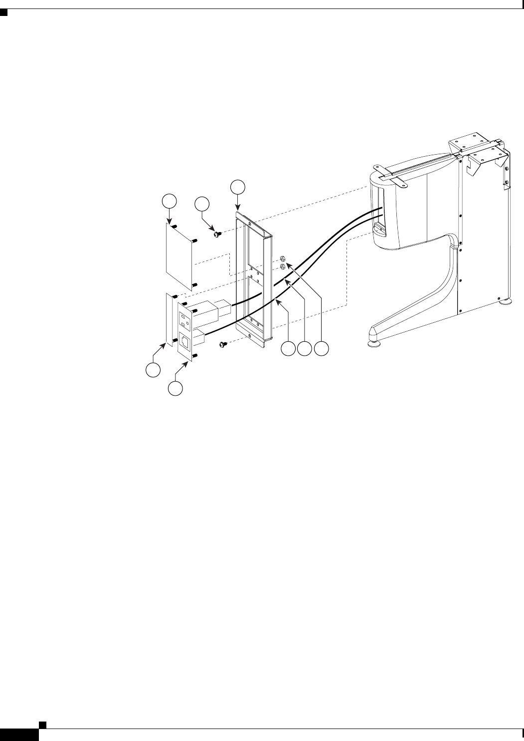
7-14
Cisco TelePresence System 3200
OL-14521-01
Chapter 7 Building the Second Row Table Assembly
Parts List
Step 11 Assemble the I/O modules for the outside left and outside right molded foam bumpers.
The outside left and outside right molded foam bumpers only have one I/O module each. The inner
molded foam bumpers have two (see Figure 7-12).
Figure 7-11 Foam Bumper Assembly
204179
43
46
44
45
50
47 48 49
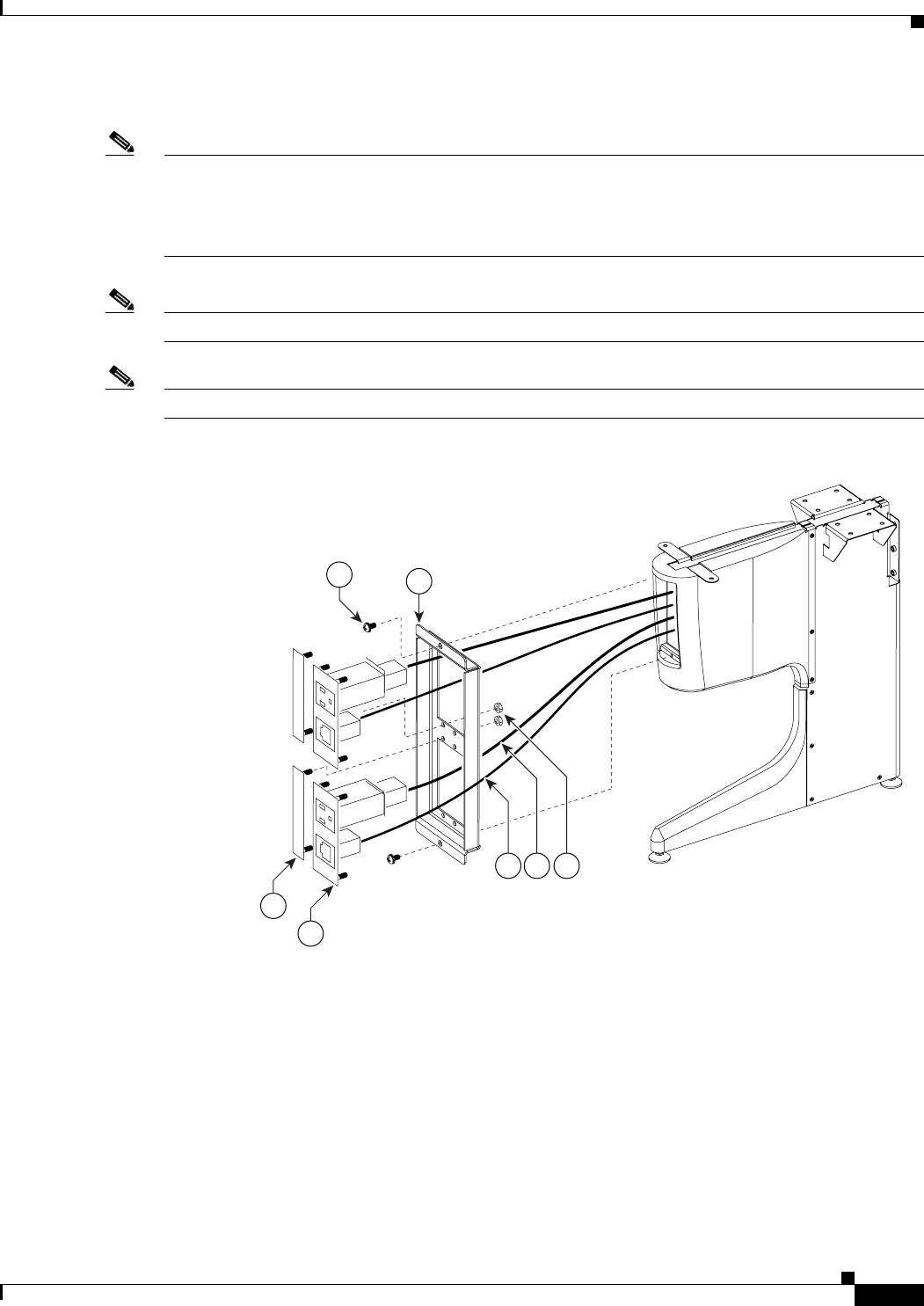
7-15
Cisco TelePresence System 3200
OL-14521-01
Chapter 7 Building the Second Row Table Assembly
Parts List
Step 12 Assemble the I/O modules for the inner molded foam bumpers.
Note The Ethernet cables are of different lengths. Attach the Ethernet cables to the I/O modules as follows:
• Use the 12M cable, 37-0965-01, for the I/O modules between sections 6 and 5
• Use the 3M cable, 37-0887-02, for the I/O modules between sections 5 and 7
Note Steps for routing the Ethernet and power cables are in Chapter 9, “Routing Power and Signal Cables.”
Note The flange on the I/O module cover piece is wider on the bottom than on the top.
Figure 7-12 Foam Bumper Assembly
204175
46
45
44
50
47 48 49
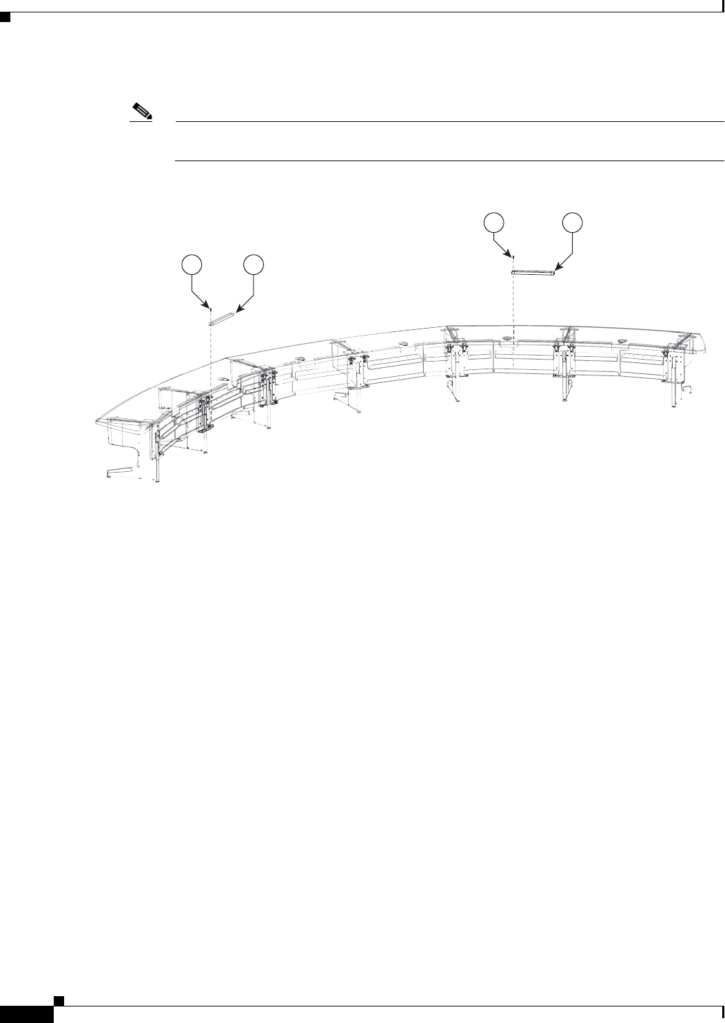
7-16
Cisco TelePresence System 3200
OL-14521-01
Chapter 7 Building the Second Row Table Assembly
Parts List
Step 13 Insert the second row PDUs in the lower cable gutters.
Note You install the remaining PDUs and route the cables in Chapter 9, “Routing Power and Signal
Cables.”
Figure 7-13 PDU Cable Routing
55
55 54
54
204171
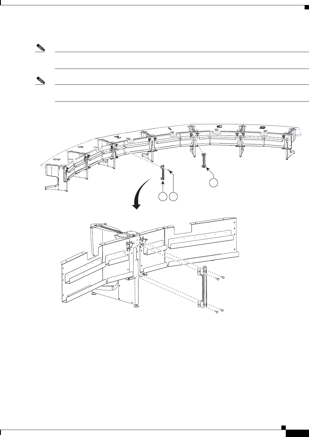
7-17
Cisco TelePresence System 3200
OL-14521-01
Chapter 7 Building the Second Row Table Assembly
Parts List
Step 14 Attach the first set of floating brackets to the table assembly.
Note Before you attach the floating brackets, route the Ethernet and power cables in Chapter 9, “Routing
Power and Signal Cables.”
Note After you attach the brackets with the shoulder screws, move the brackets left and right to ensure that
they can move freely.
Figure 7-14 Floating Brackets, Type 1
204169
12
12 56
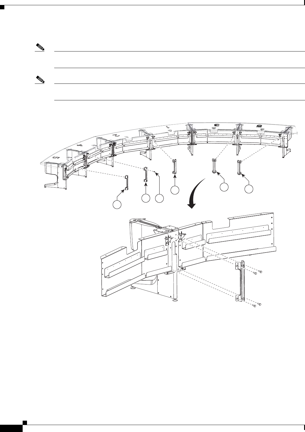
7-18
Cisco TelePresence System 3200
OL-14521-01
Chapter 7 Building the Second Row Table Assembly
Parts List
Step 15 Attach the second set of floating brackets to the table assembly.
Note Before you attach the floating brackets, route the power cables in Chapter 9, “Routing Power and Signal
Cables.”
Note After you attach the brackets with the shoulder screws, move the brackets left and right to ensure that
they can move freely.
Figure 7-15 Floating Brackets, Type 2
204170
1313
13
13
13
56
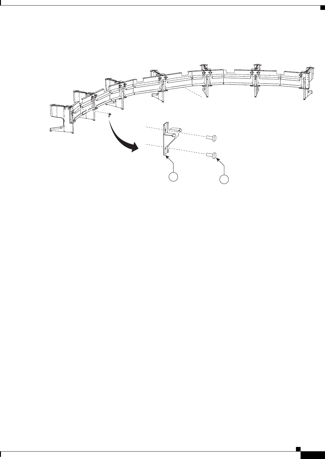
7-19
Cisco TelePresence System 3200
OL-14521-01
Chapter 7 Building the Second Row Table Assembly
Parts List
Step 16 Attach the privacy panel hangers to the table assembly.
Figure 7-16 Privacy Panel Hanger
204109
11 35
7-20
Cisco TelePresence System 3200
OL-14521-01
Chapter 7 Building the Second Row Table Assembly
Parts List
Step 17 Place the section 1 and section 2 tabletops on the table assembly, insert the plastic spline in the slot of
table section 1, and join the tables together, then insert and tighten the draw bolts evenly on each side
until the tabletop sections are joined together.
Note As you build the table tops, attempt to align the table feet with the table tops, and make sure that they
table tops are supported on at least three sides.
Figure 7-17 Tabletop Sections 1 and 2, Spline And Draw Bolts
204111
15
14
39
40
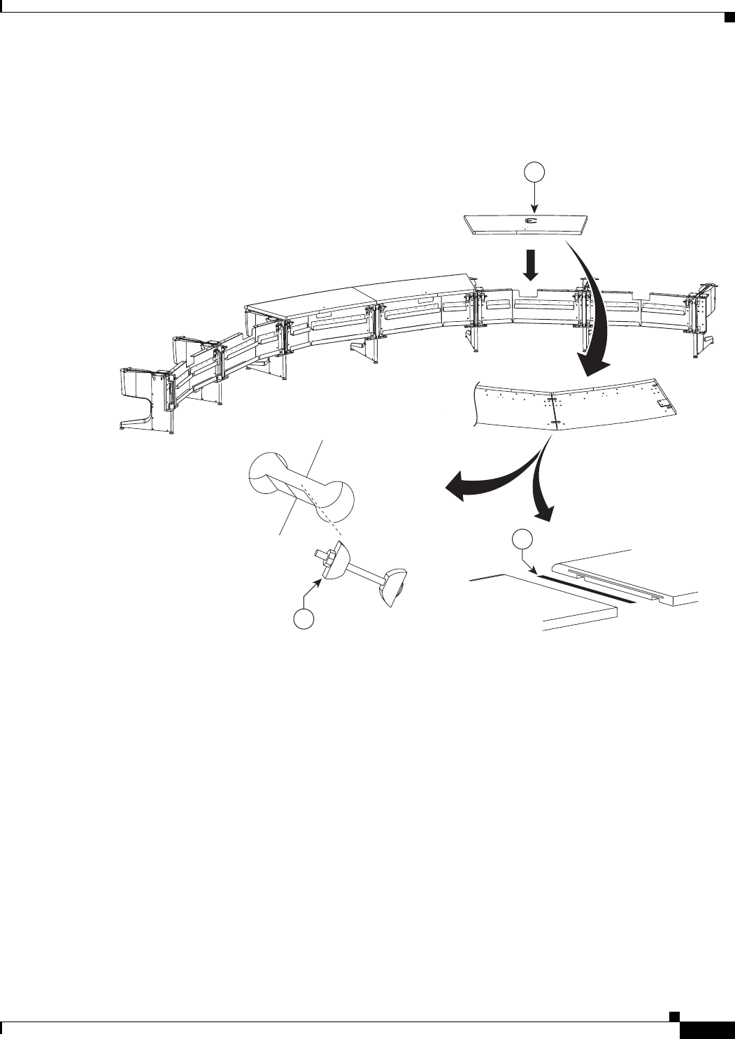
7-21
Cisco TelePresence System 3200
OL-14521-01
Chapter 7 Building the Second Row Table Assembly
Parts List
Step 18 Place the Section 3 tabletop on the table assembly, insert the spline in the slot between the two tabletops,
and use the draw bolts to join table tops 1 and 3 together.
Figure 7-18 Tabletop Section 3
204112
39
40
16
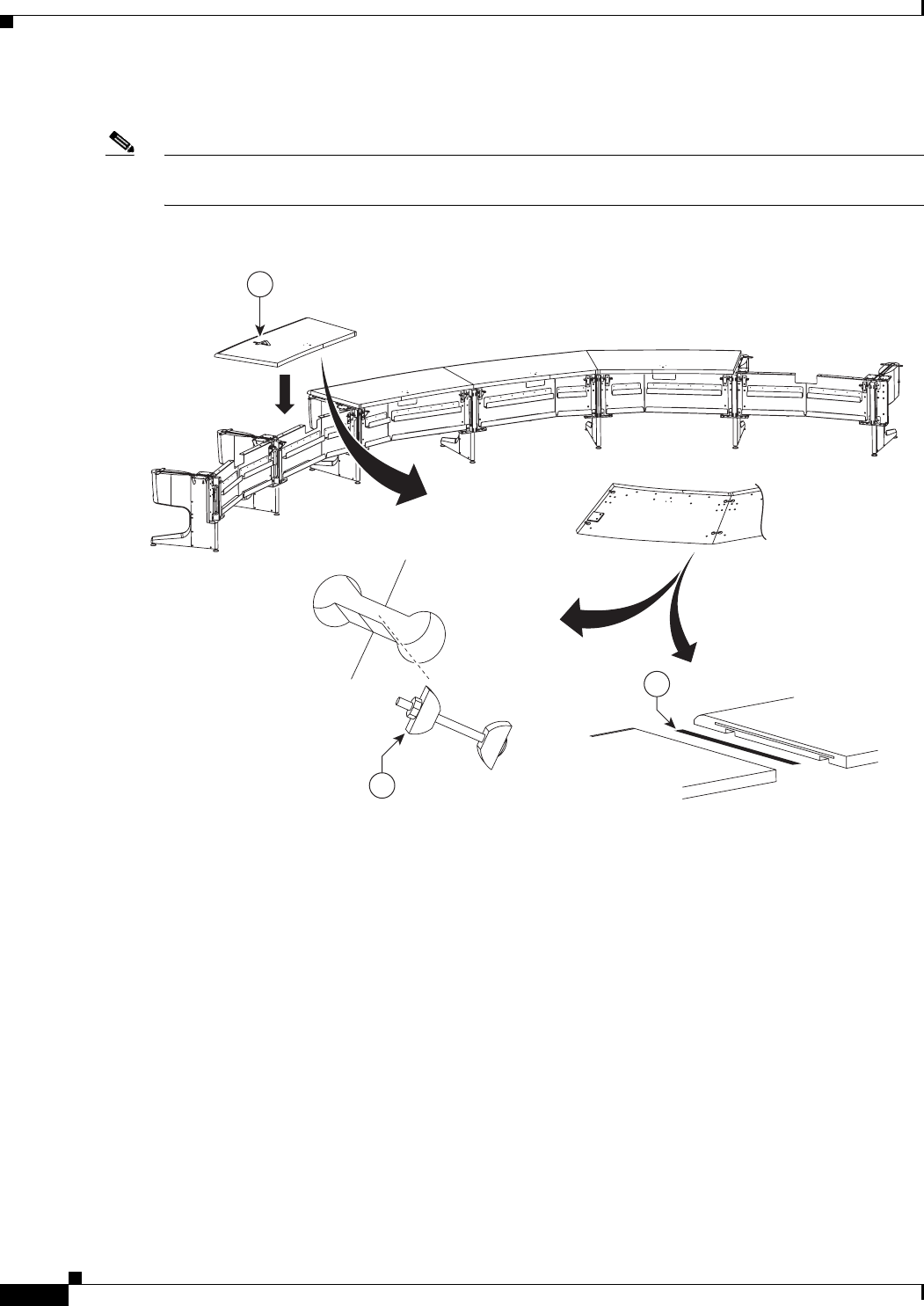
7-22
Cisco TelePresence System 3200
OL-14521-01
Chapter 7 Building the Second Row Table Assembly
Parts List
Step 19 Join table section 4 to table section 2 using the draw bolts and spline.
Note If you are building a Reduced Configuration table (four tabletops instead of six), continue to Step 22
after completing this step.
Figure 7-19 Tabletop Section 4
204113
39
40
17
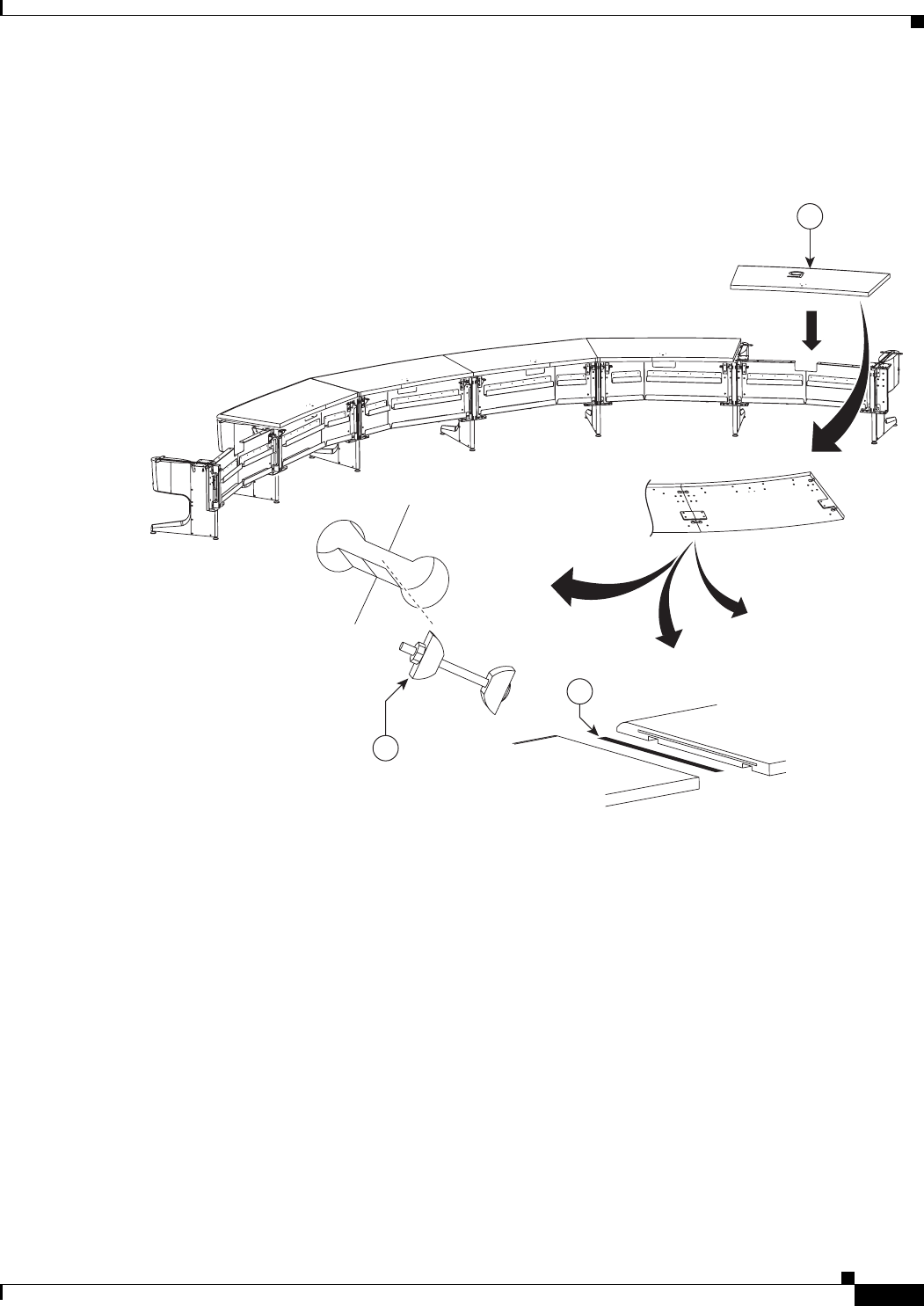
7-23
Cisco TelePresence System 3200
OL-14521-01
Chapter 7 Building the Second Row Table Assembly
Parts List
Step 20 Place the left tabletop section 5 on the table assembly and join it to the section 3 tabletop using the draw
bolts and spline.
Figure 7-20 Tabletop Section 5 (Left)
204114
39
40
18
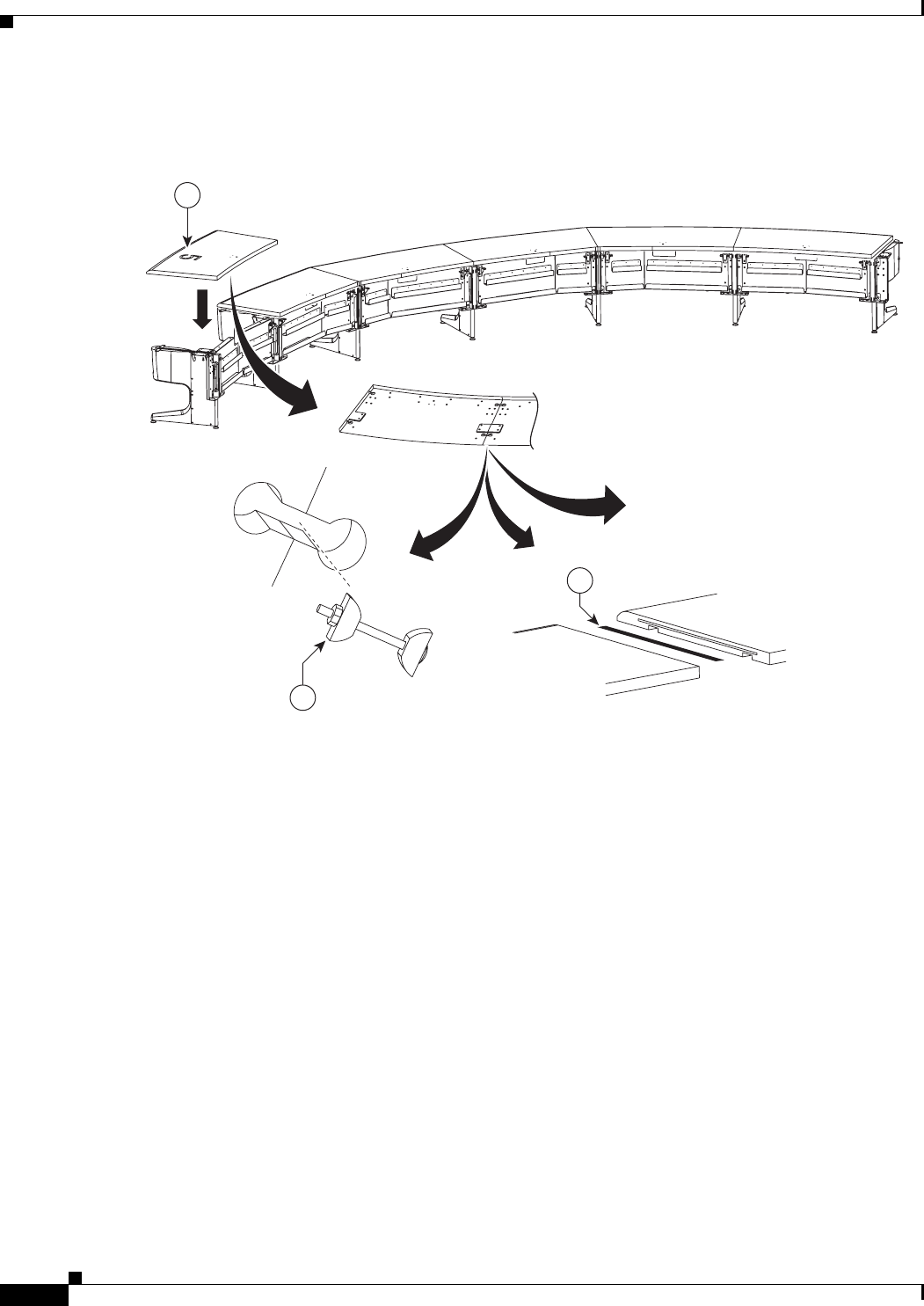
7-24
Cisco TelePresence System 3200
OL-14521-01
Chapter 7 Building the Second Row Table Assembly
Parts List
Step 21 Place the right tabletop section 5 on the table assembly and join it to the section 4 tabletop.
Figure 7-21 Tabletop Section 5 (Right)
204115
39
40
18
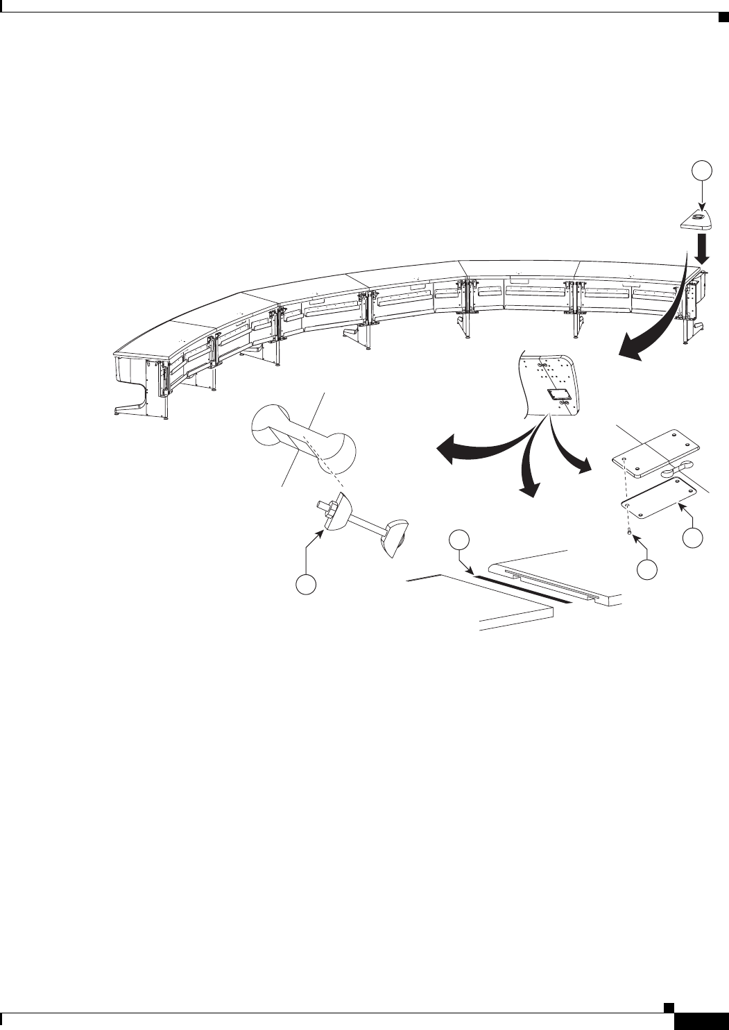
7-25
Cisco TelePresence System 3200
OL-14521-01
Chapter 7 Building the Second Row Table Assembly
Parts List
Step 22 Attach the left tabletop end to tabletop section 5 using the using the draw bolts, spline and alignment
plate.
Figure 7-22 Left Tabletop End, Draw Bolts, Spline and Alignment Plate
204116
39
40 34
35
19
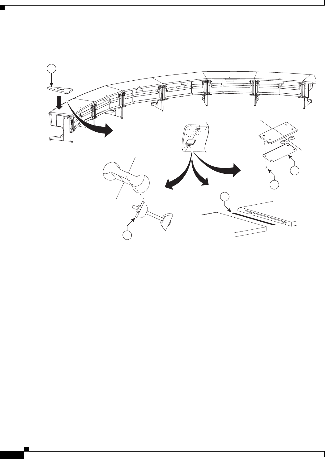
7-26
Cisco TelePresence System 3200
OL-14521-01
Chapter 7 Building the Second Row Table Assembly
Parts List
Step 23 Attach the Right tabletop end.
Figure 7-23 Right Tabletop End
204117
39
40
34
35
20
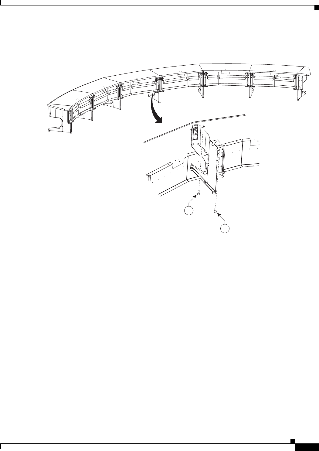
7-27
Cisco TelePresence System 3200
OL-14521-01
Chapter 7 Building the Second Row Table Assembly
Parts List
Step 24 Attach tabletop sections 1 and 2 to the table leg.
Figure 7-24 Tabletop Sections 1 and 2 and Table Leg
35
35
204118
7-28
Cisco TelePresence System 3200
OL-14521-01
Chapter 7 Building the Second Row Table Assembly
Parts List
Step 25 Attach tabletop sections 1 and 3 to the table leg.
Figure 7-25 Tabletop Sections 1 and 3 and Table Leg
204119
35
35
7-29
Cisco TelePresence System 3200
OL-14521-01
Chapter 7 Building the Second Row Table Assembly
Parts List
Step 26 Attach tabletop sections 2 and 4 to the table leg.
Note If you are building a Reduced Configuration table (four tabletops instead of six), continue to Step 30
after completing this step.
Figure 7-26 Tabletop Sections 2 and 4 and Table Leg
204120
35
35
7-30
Cisco TelePresence System 3200
OL-14521-01
Chapter 7 Building the Second Row Table Assembly
Parts List
Step 27 Attach tabletop sections 3 and 5 to the table leg.
Figure 7-27 Tabletop Sections 3 and 5 and Table Leg
35
35
204121
7-31
Cisco TelePresence System 3200
OL-14521-01
Chapter 7 Building the Second Row Table Assembly
Parts List
Step 28 Attach tabletop sections 4 and 5 to the table leg.
Figure 7-28 Tabletop Sections 4 and 5 and Table Leg
35
35
204122
7-32
Cisco TelePresence System 3200
OL-14521-01
Chapter 7 Building the Second Row Table Assembly
Parts List
Step 29 Attach the reinforcement screws for the gutter panels.
Figure 7-29 Gutter Panel Reinforcement Screws
204182
35
35
35
35
7-33
Cisco TelePresence System 3200
OL-14521-01
Chapter 7 Building the Second Row Table Assembly
Parts List
Step 30 Attach the panel end brace to the table leg and left tabletop end and attach the table leg to the tabletop
and tabletop end.
Figure 7-30 Panel End Braces, Table Leg, Left Tabletop End and Table Section 5
35
35
21
35
204123
7-34
Cisco TelePresence System 3200
OL-14521-01
Chapter 7 Building the Second Row Table Assembly
Parts List
Step 31 Attach the panel end brace to the table leg and right tabletop end, then attach the table leg to the tabletop
and tabletop end.
Figure 7-31 Panel End Braces, Table Leg, Right Tabletop End and Table Section 5
Step 32 Attach the privacy panel alignment bracket to the underside of table section 1.
Figure 7-32 Section 1 Privacy Panel Alignment Bracket
35
35
3521
204124
35
22
204125
7-35
Cisco TelePresence System 3200
OL-14521-01
Chapter 7 Building the Second Row Table Assembly
Parts List
Step 33 Attach the privacy panel alignment bracket to the underside of table section 2.
Figure 7-33 Section 2 Privacy Panel Alignment Bracket
Step 34 Attach the privacy panel alignment bracket to the underside of table section 3.
Figure 7-34 Section 3 Privacy Panel Alignment Bracket
35
23
204126
25
24
204127
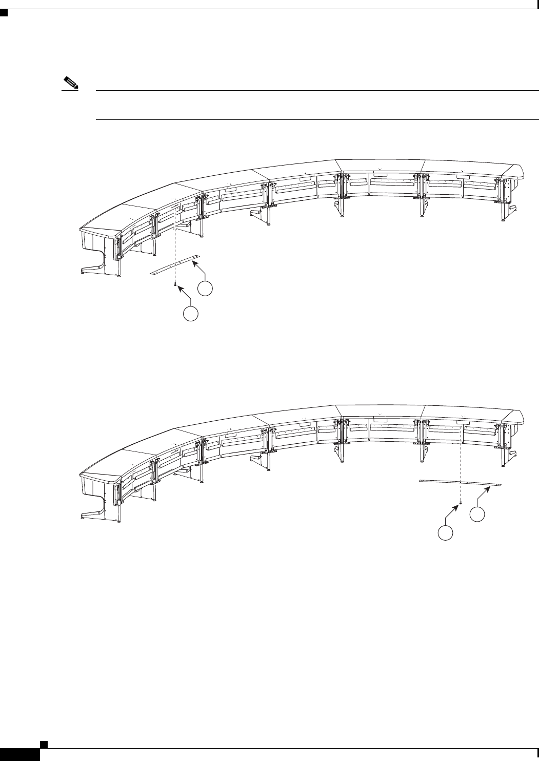
7-36
Cisco TelePresence System 3200
OL-14521-01
Chapter 7 Building the Second Row Table Assembly
Parts List
Step 35 Attach the privacy panel alignment bracket to the underside of table section 4.
Note If you are building a Reduced Configuration table (four tabletops instead of six), continue to Step 38
after completing this step.
Figure 7-35 Section 4 Privacy Panel Alignment Bracket
Step 36 Attach the privacy panel alignment bracket to the underside of left table section 5.
Figure 7-36 Left Section 5 Privacy Panel Alignment Bracket
35
25
204128
35
28
204129
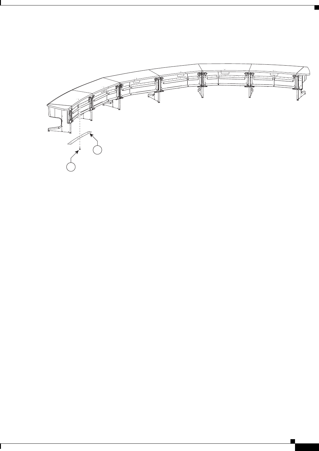
7-37
Cisco TelePresence System 3200
OL-14521-01
Chapter 7 Building the Second Row Table Assembly
Parts List
Step 37 Attach the privacy panel alignment bracket to the underside of right table section 5.
Figure 7-37 Right Section 5 Privacy Panel Alignment Bracket
28
35
204130
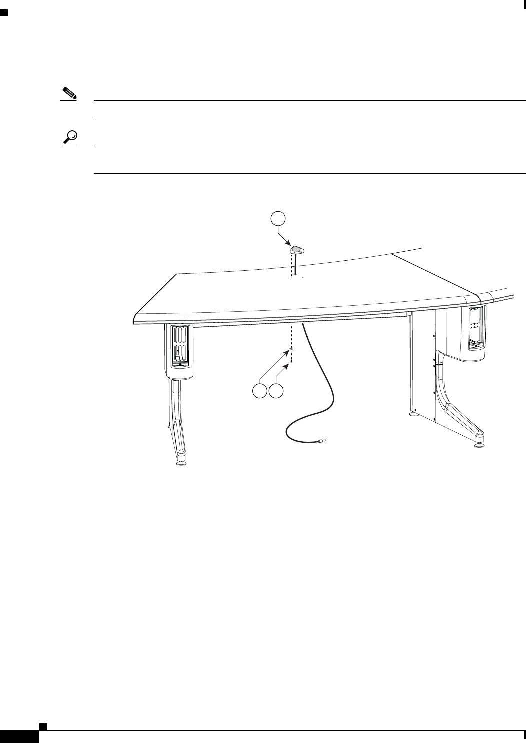
7-38
Cisco TelePresence System 3200
OL-14521-01
Chapter 7 Building the Second Row Table Assembly
Parts List
Step 38 Attach one microphone to each table segment and attach the microphone extension cords to the
microphone cables. There are six microphones for the second row table.
Note Steps for routing the microphone cables are in Chapter 9, “Routing Power and Signal Cables.”
Tip Label each microphone cable where it exits from the table. You attach the microphones to the
Audio/Video Expansion Unit in Chapter 9, “Routing Power and Signal Cables.”
Figure 7-38 Microphone Assembly
204180
5253
51
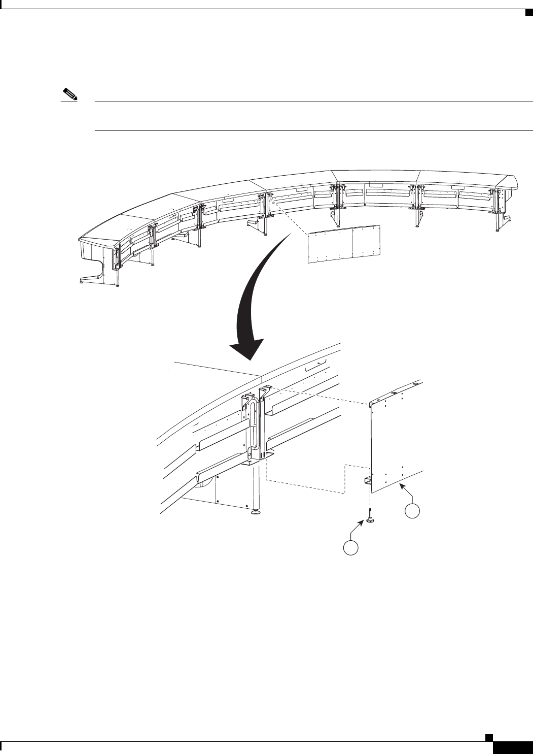
7-39
Cisco TelePresence System 3200
OL-14521-01
Chapter 7 Building the Second Row Table Assembly
Parts List
Step 39 Lift the privacy panel for table section 1 into position until it seats on the locating pins on the table
assembly; then, use the plastic knob screws to loosely attach the privacy panel from below.
Note Do not fully tighten the screws until you attach all privacy panels. You perform final spacing adjustments
after you attach the last panel.
Figure 7-39 Section 1 Privacy Panel
27
38
204131
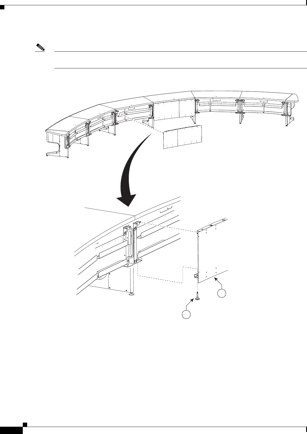
7-40
Cisco TelePresence System 3200
OL-14521-01
Chapter 7 Building the Second Row Table Assembly
Parts List
Step 40 Attach the privacy panel for section 2 to the table assembly.
Note Align the panels so that the seam between privacy panels 1 and 2 is aligned with the table top seam for
table tops 1 and 2.
Figure 7-40 Section 2 Privacy Panel
28
38
204132
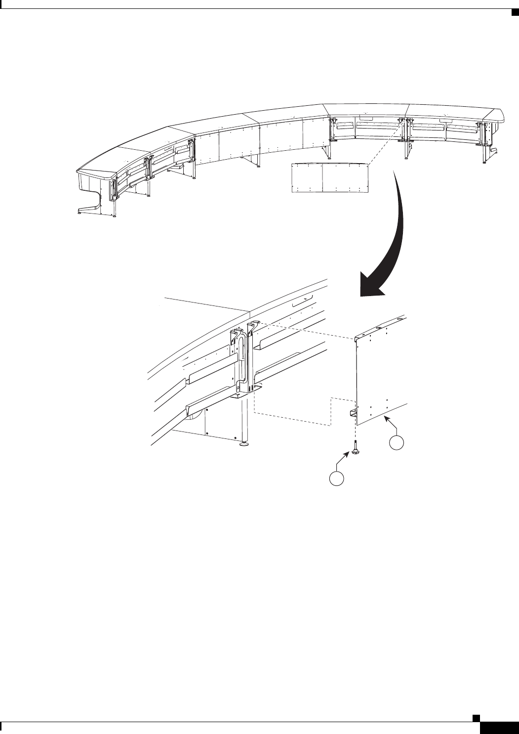
7-41
Cisco TelePresence System 3200
OL-14521-01
Chapter 7 Building the Second Row Table Assembly
Parts List
Step 41 Attach the privacy panel for section 3 to the table assembly.
Figure 7-41 Section 3 Privacy Panel
29
38
204133
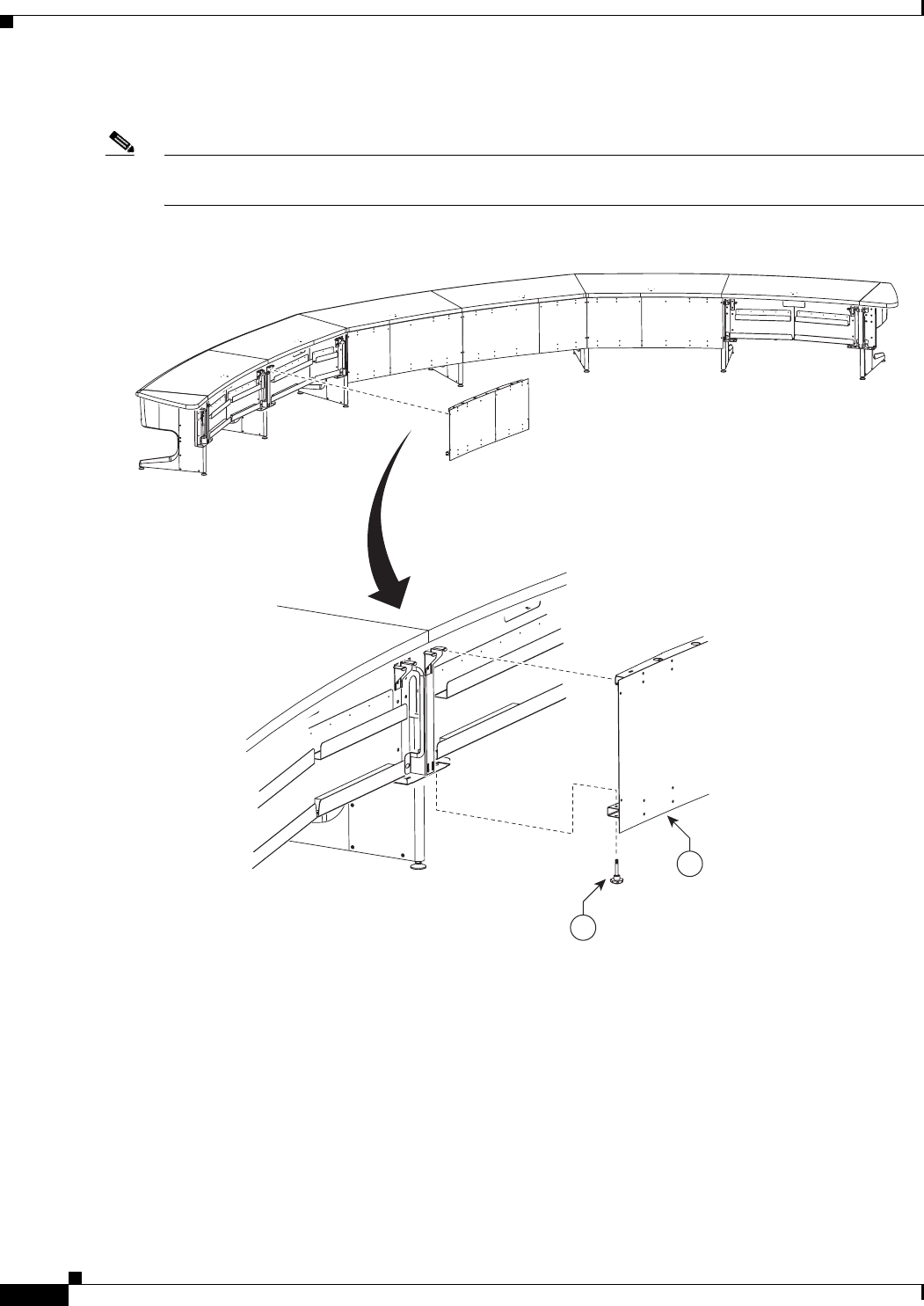
7-42
Cisco TelePresence System 3200
OL-14521-01
Chapter 7 Building the Second Row Table Assembly
Parts List
Step 42 Attach the privacy panel for section 4 to the table assembly.
Note If you are building a Reduced Configuration table (four tabletops instead of six), continue to Step 45
after completing this step.
Figure 7-42 Section 4 Privacy Panel
30
38
204134
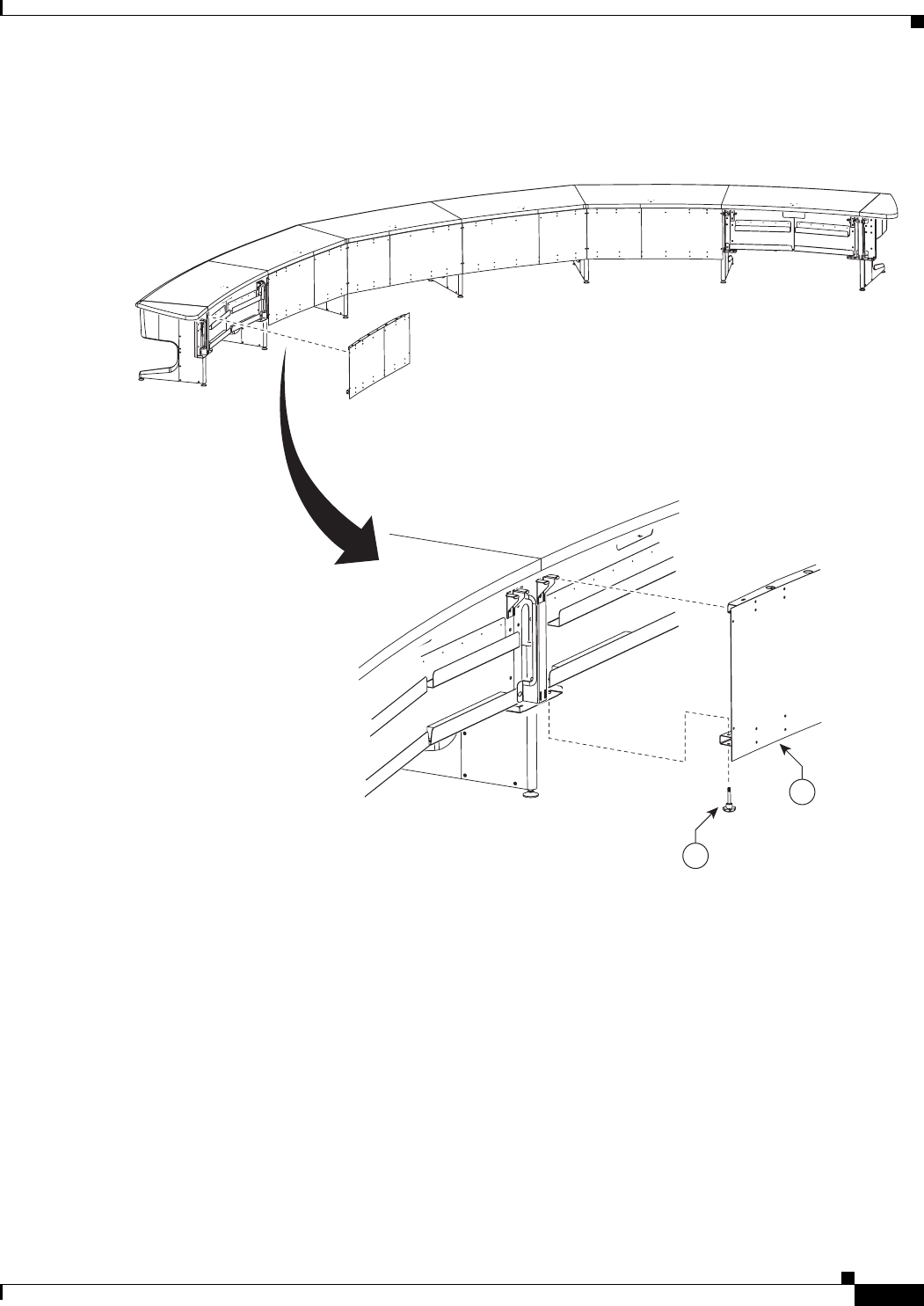
7-43
Cisco TelePresence System 3200
OL-14521-01
Chapter 7 Building the Second Row Table Assembly
Parts List
Step 43 Attach the privacy panel for left section 5 to the table assembly.
Figure 7-43 Left Section 5 Privacy Panel
31
38
204135
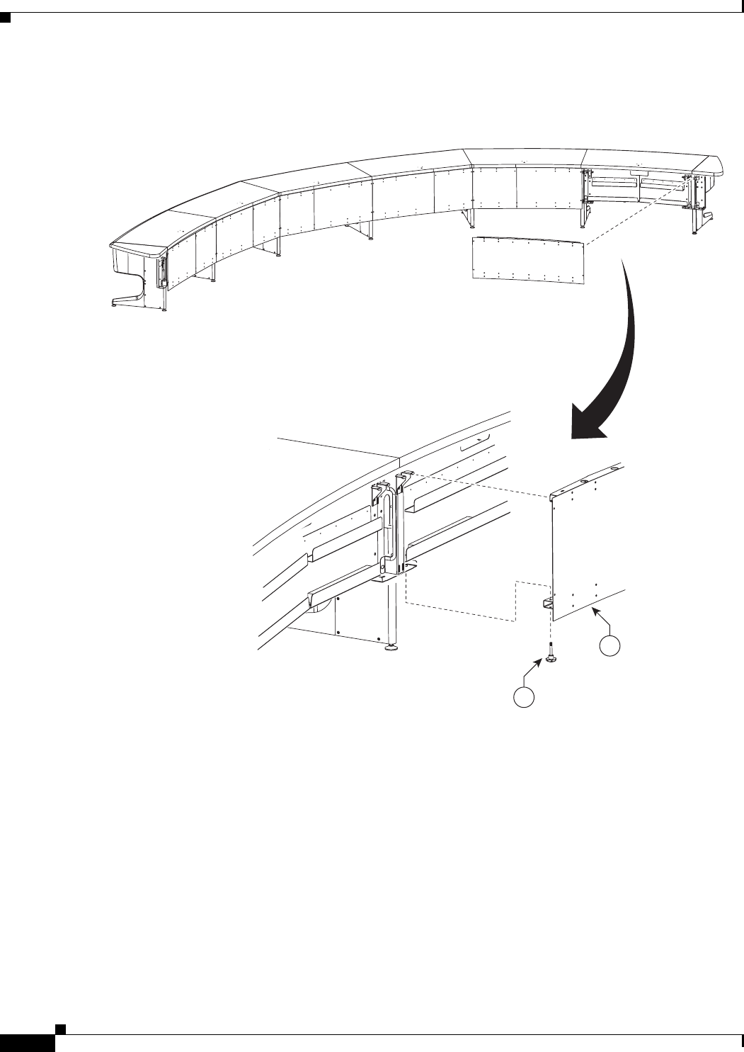
7-44
Cisco TelePresence System 3200
OL-14521-01
Chapter 7 Building the Second Row Table Assembly
Parts List
Step 44 Attach the privacy panel for right section 5 to the table assembly.
Figure 7-44 Section 5 Privacy Panel
31
38
204136
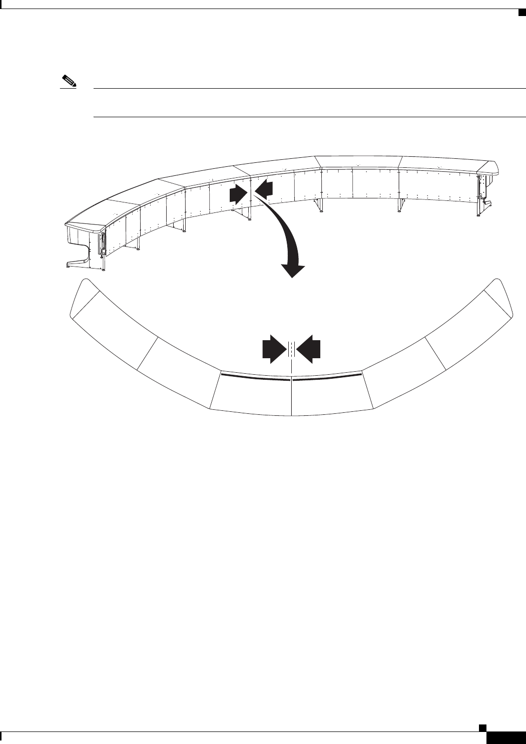
7-45
Cisco TelePresence System 3200
OL-14521-01
Chapter 7 Building the Second Row Table Assembly
Parts List
Step 45 Adjust panels until all seams between the panels are even, then fully tighten the knob screws.
Note Start with the seam between sections 1 and 2. The seam between the table tops should align with the
seam between the privacy panels.
Figure 7-45 Adjusting the Privacy Panels
204184
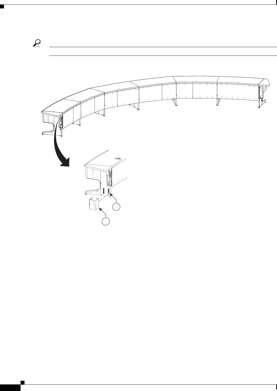
7-46
Cisco TelePresence System 3200
OL-14521-01
Chapter 7 Building the Second Row Table Assembly
Parts List
Step 46 Attach the cable cover for the right end privacy panel.
Tip Install the cable cover so that it hides the cables that come out of the right side of the table section.
Figure 7-46 Cable Cover
204173
41
42
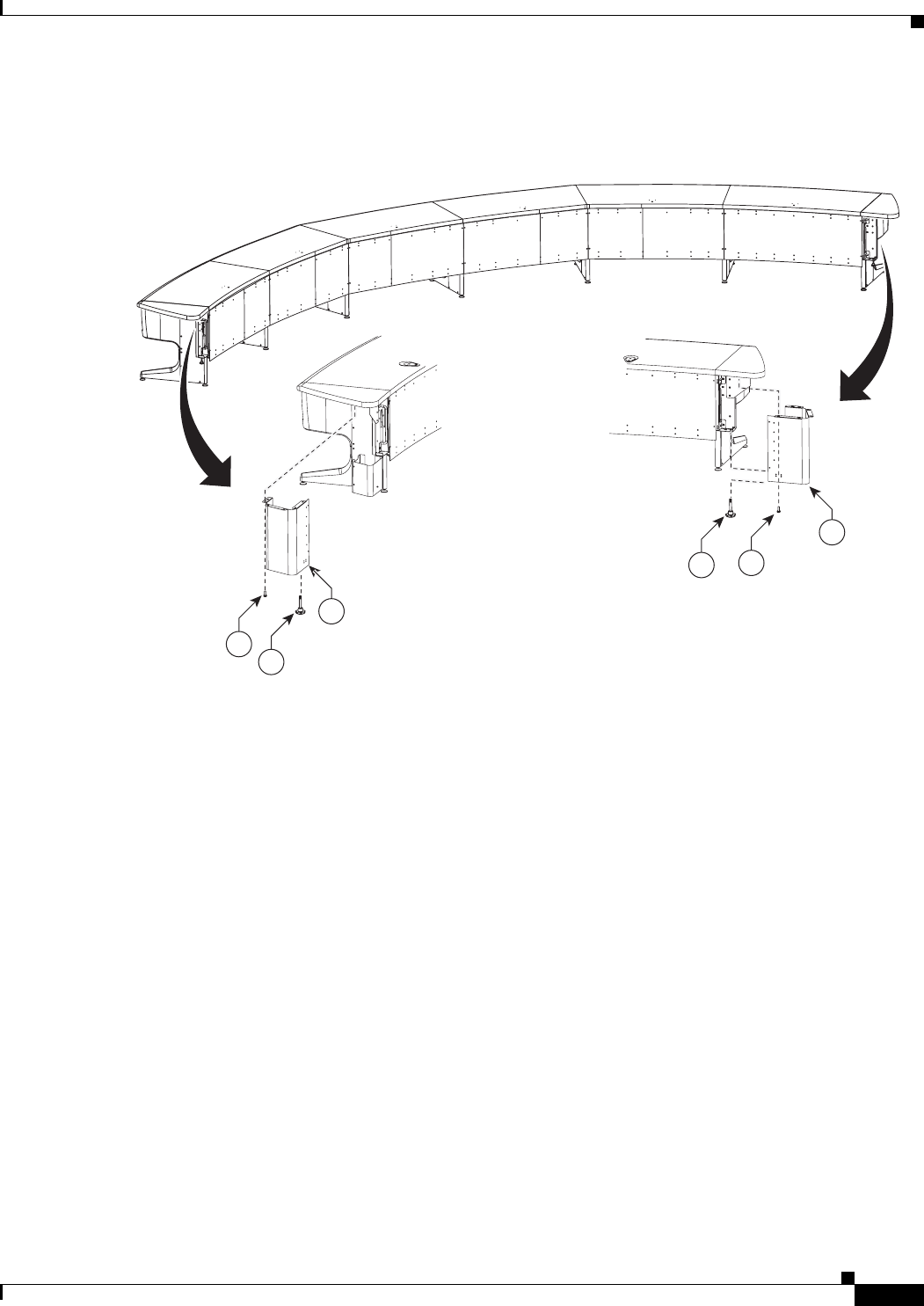
7-47
Cisco TelePresence System 3200
OL-14521-01
Chapter 7 Building the Second Row Table Assembly
Parts List
Step 47 Attach the privacy panel end pieces and the cable cover for the right end privacy panel.
Figure 7-47 Privacy Panel End Pieces
204174
35
38
32
33
35
38
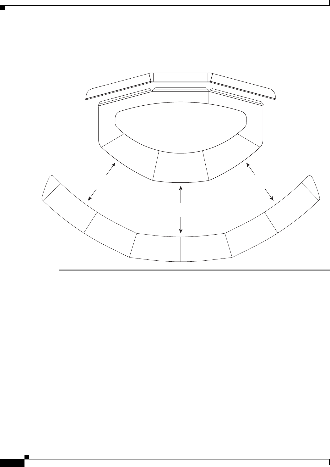
7-48
Cisco TelePresence System 3200
OL-14521-01
Chapter 7 Building the Second Row Table Assembly
Parts List
Step 48 Position the second row table so that the trailing edge of the first row table is exactly 59 inches (150 cm)
behind the leading edge of the second row table.
Figure 7-48 Second Row Table Positioning
59” (150 cm)
59” (150 cm)
59” (150 cm)
204151
CHAPTER
8-1
Cisco TelePresence System 3200
OL-14521-01
8
Assembling the Remaining Cisco TelePresence
Elements
Revised: July 28, 2008, OL-14521-01
Parts List
Key Part Description Part Number Qty Ctn Notes
Camera and Camera Assembly
1Camera assembly 68-3277-xx 1 4
8M8 x 20 mm pan head screws 48-2410-xx 4 1 Used to attach to the Camera
assembly bracket on the center
Display structure.
7M4 x 20mm cap screws 48-0654-xx 4 N/A These screws are included with the
camera assembly and are used to
attach the top and bottom hoods to the
camera assembly.
Projector Assembly
1Projector 74-4824-xx 1 7
2Projector mounting bracket 700-23824-xx 1 45
3VGA Module 69-1691-xx 1 1
4M8 x 20 mm screws 48-2273-xx 1
5M6 x 10 mm screws 48-1963-xx 4 1
6M8 washers 48-2273-xx 1

8-2
Cisco TelePresence System 3200
OL-14521-01
Chapter 8 Assembling the Remaining Cisco TelePresence Elements
Parts List
Codec Assembly
1Primary codec 84-1321-xx 1 3
2Secondary codec 68-2898-xx 2 5, 6,
40
3Cable management bar 700-23449-xx 3 3, 5,
6, 40
4Codec attachment brackets 700-23342-xx 6 13
5M4 x 12 mm screws 48-1045-xx 20 1
6M4 washers 49-0735-xx 20 1
Speaker Assembly
1Speaker 74-4740-xx 3 8
2Speaker boards left and right 74-5544-xx 2 58
3Speaker board center 74-5307-xx 1 58
4Speaker cable 37-0849-xx 3 1
5Leveling foot 51-4540-xx 6 1
6Half-turn bolt 48-2275-xx 6 1
7Speaker board brackets 700-23944-xx 6 13
8M8 x 20 mm screws 48-2273-xx 1
9M8 washers 49-1165-xx 1
Cisco Unified IP Phone CP-7975G CP-7975G-CTS
68-3309-xx
1 1 The IP Phone should be placed near
the right wing Table segment to
prevent it from appearing on screen.
Projector Screen Assembly, Type 1 800-28681-xx 1 46
Projector Screen Assembly, Type 2 CTS3K-SCREEN
74-5416-xx
1 46 Your system ships with either a Type
1 or Type 2 screen. Refer to the
projector screen installation guide
that is packaged with the assembly to
install the screen.
Audio/Video Extension Unit
1Mounting bracket for audio/video
extension unit
700-26833-xx 1 1
2audio/video extension unit 73-11609-02
800-30442-xx
11
Auxiliary Control Unit
1Auxiliary Control Unit CTS-LIGHT-CTRL
74-5405-xx
122
Camera Target Assembly
1Tabletop camera target: large 700-24323-xx 1 32
2Tabletop camera target: small 700-24320-xx 1 32
3Cardboard ruler 700-24321-xx 1 32
4Vertical bar 700-23961-xx 2 32
Key Part Description Part Number Qty Ctn Notes

8-3
Cisco TelePresence System 3200
OL-14521-01
Chapter 8 Assembling the Remaining Cisco TelePresence Elements
Parts List
Note Note that the key numbers restart for each element.
Warning
Only trained and qualified personnel should be allowed to install, replace, or service this equipment.
Note The directions left and right refer to the assembly as you face it from the front.
5Horizontal bar 700-23960-xx 2 32
6M4 x 20 mm screws 48-0654-xx 4 1
Switch Bracket
Note There are two additional brackets included with the accessory cabinet in Carton 33: 700-23338-xx and
700-23344-xx. These brackets attach the optional Ethernet switch to the left accessory cabinet. If you ordered this
switch, refer to the Cisco TelePresence System Hardware Options & Upgrade Guide to install the switch.
Key Part Description Part Number Qty Ctn Notes
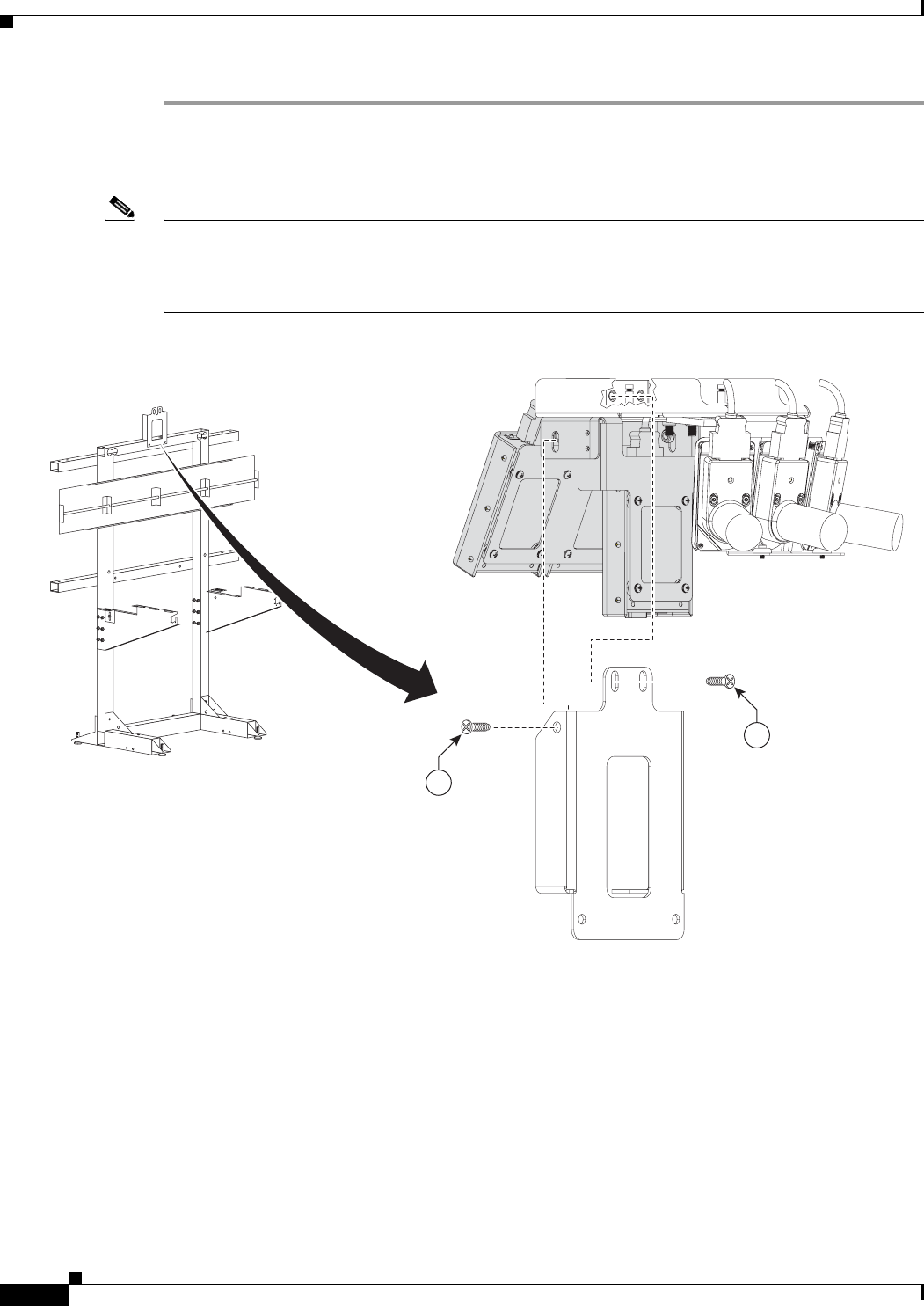
8-4
Cisco TelePresence System 3200
OL-14521-01
Chapter 8 Assembling the Remaining Cisco TelePresence Elements
Parts List
Step 1 Place the assembly over the center display, then attach the Camera Assembly to the Camera Assembly
bracket.
For clarity, the display has been removed from the illustration in Figure 8-1.
Note There are two foam pads on inside of the camera assembly. Make sure that the foam pad on the top of
the camera assembly touches the top of the display, and the foam pad on the front of the assembly
touches the front of the display. To make adjustments, loosen the four screws on the top of the camera
assembly and move the assembly forward or back as required; then, retighten the four screws.
Figure 8-1 Camera Assembly
8
8
201164

8-5
Cisco TelePresence System 3200
OL-14521-01
Chapter 8 Assembling the Remaining Cisco TelePresence Elements
Parts List
Step 2 Attach the projector to the projector mounting bracket.
Figure 8-2 Projector Assembly
201168
2
1
5
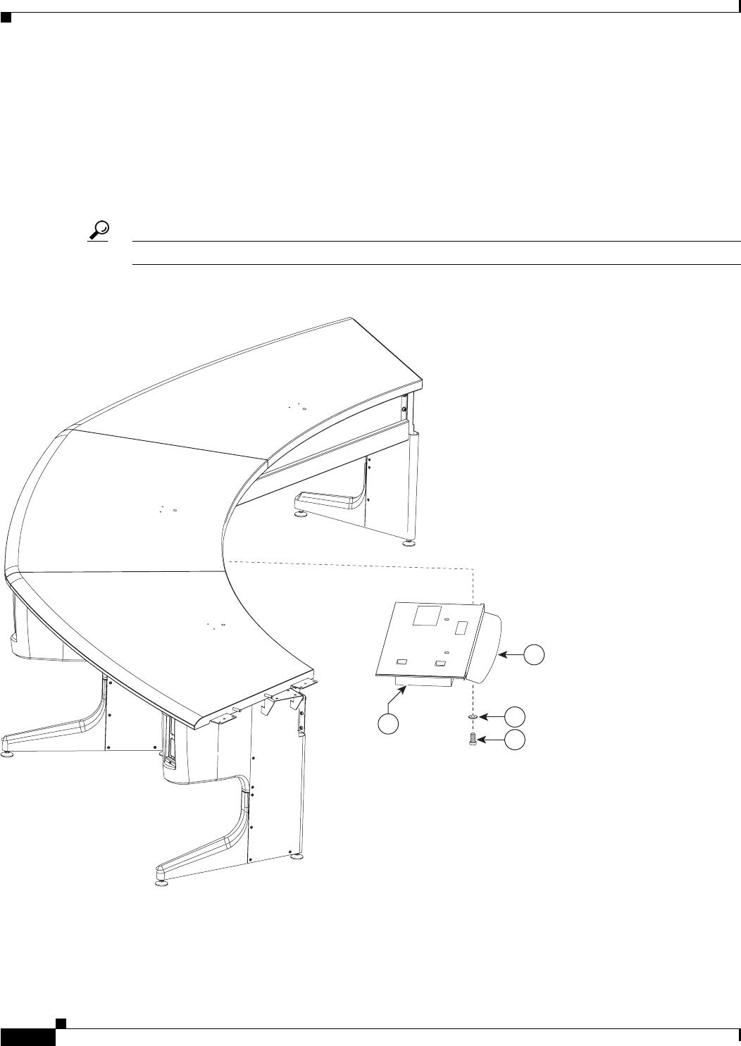
8-6
Cisco TelePresence System 3200
OL-14521-01
Chapter 8 Assembling the Remaining Cisco TelePresence Elements
Parts List
Step 3 Attach the projector to the projector mounting bracket, and attach the assembly to the underside of the
center Table segment.
a. Make sure the center Microphone cable is routed securely within the cable channel on the underside
of the center Table segment before attaching the Projector mounting bracket.
a. Insert the screws and washers in the underside of the center Table segment to prepare for attaching
the Projector mounting bracket; then, slide the bracket between the two rows of screws and tighten
the screws.
Tip If you have clearance issues, remove the center privacy panel segment before you mount the projector.
Figure 8-3 Projector Assembly
201169
2
6
4
1
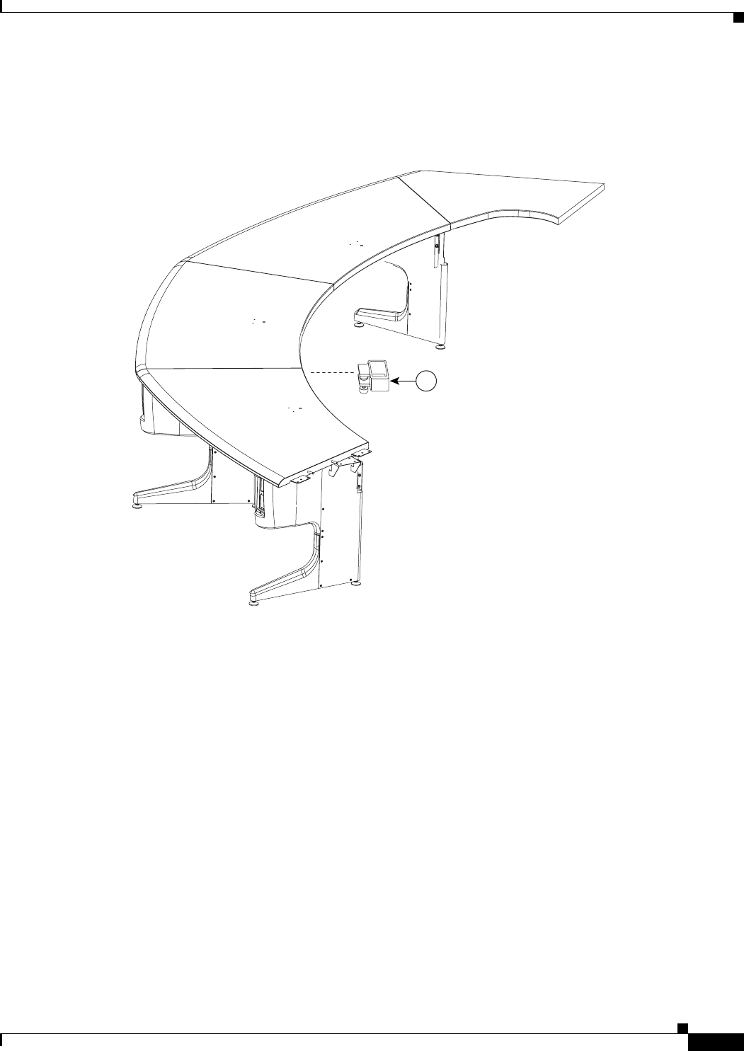
8-7
Cisco TelePresence System 3200
OL-14521-01
Chapter 8 Assembling the Remaining Cisco TelePresence Elements
Parts List
Step 4 Attach the VGA module to the center Table segment.
The VGA module supports the VGA peripheral cable when not in use.
Figure 8-4 Projector Assembly
3
201170
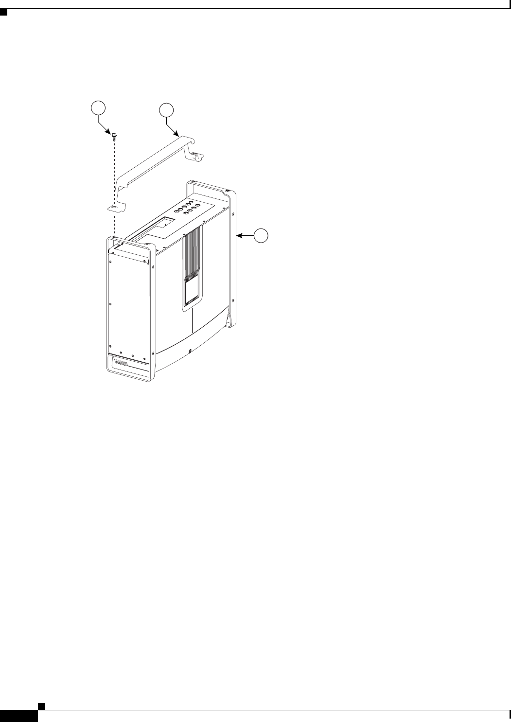
8-8
Cisco TelePresence System 3200
OL-14521-01
Chapter 8 Assembling the Remaining Cisco TelePresence Elements
Parts List
Step 5 Attach the Cable management bars to the three Codecs.
Figure 8-5 Codec Assembly
1
53
201175
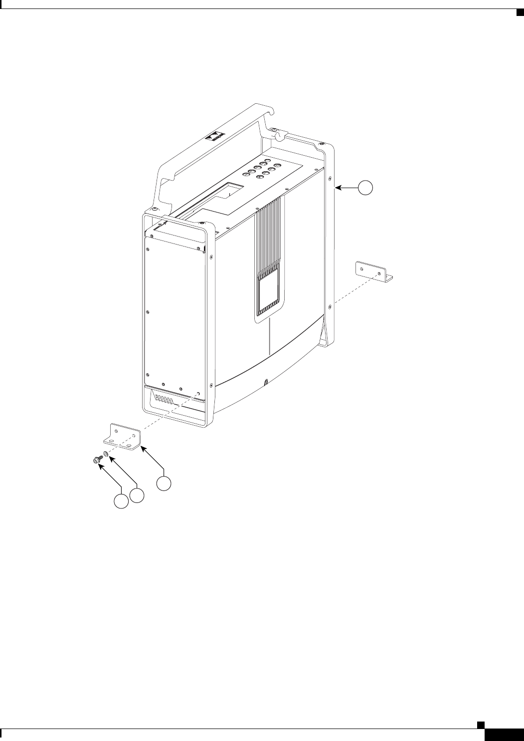
8-9
Cisco TelePresence System 3200
OL-14521-01
Chapter 8 Assembling the Remaining Cisco TelePresence Elements
Parts List
Step 6 Attach the Codec attachment brackets to the three Codecs.
Figure 8-6 Codec Assembly
201176
1
4
56
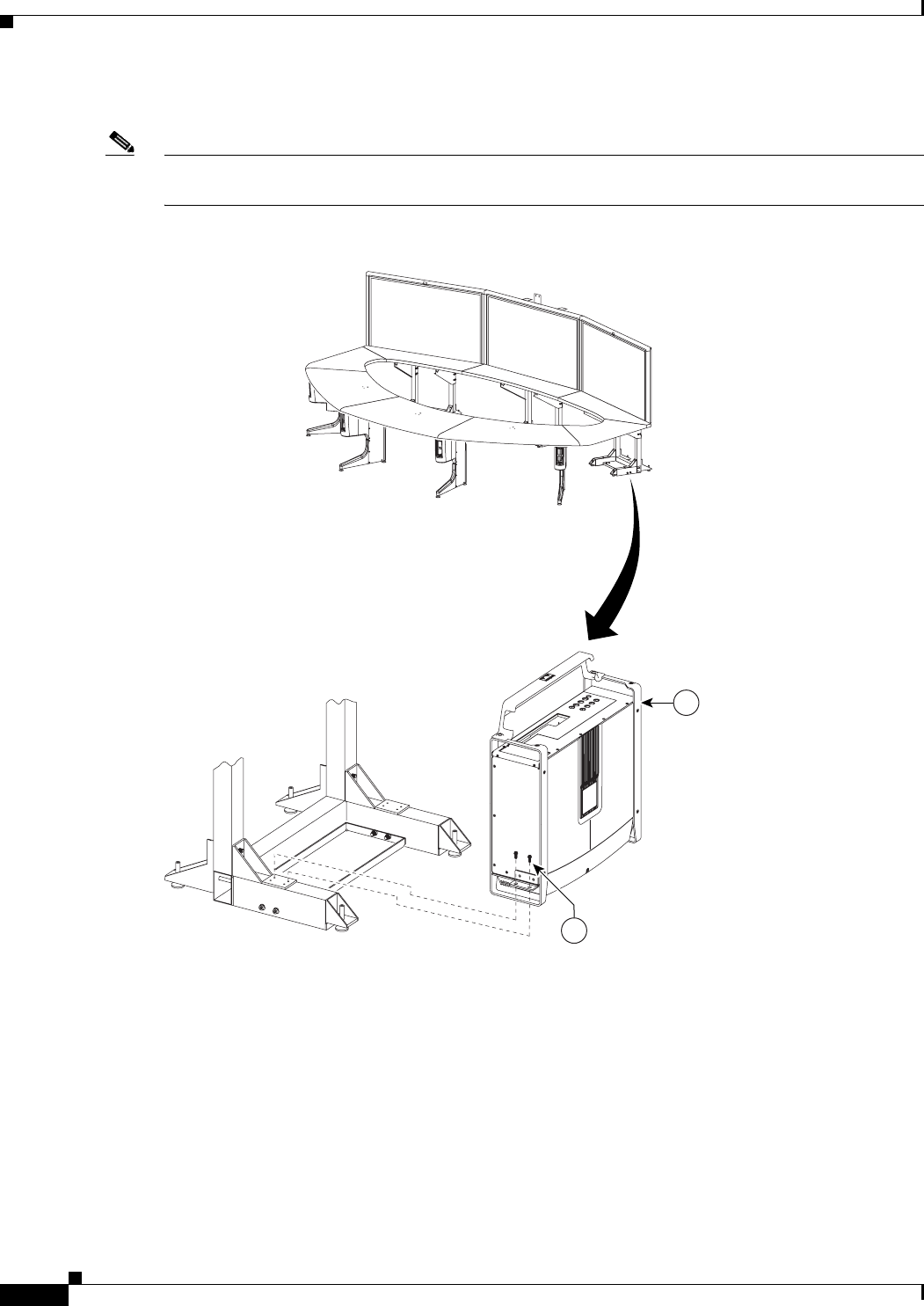
8-10
Cisco TelePresence System 3200
OL-14521-01
Chapter 8 Assembling the Remaining Cisco TelePresence Elements
Parts List
Step 7 Attach the three codecs to the display structure codec safety trays.
Note If you ordered a Presentation Codec with your TelePresence system, refer to the Cisco TelePresence
Hardware Options and Upgrade Guide for instructions to install your presentation codec.
Figure 8-7 Codec Assembly
201177
1
5
8-11
Cisco TelePresence System 3200
OL-14521-01
Chapter 8 Assembling the Remaining Cisco TelePresence Elements
Parts List
Step 8 Attach the Speaker board brackets and Leveling feet to the Speaker boards.
The Speaker board brackets should angle towards the rear of the Display structure.
Figure 8-8 Speaker Assembly
201178
7
5
98
3
2
8-12
Cisco TelePresence System 3200
OL-14521-01
Chapter 8 Assembling the Remaining Cisco TelePresence Elements
Parts List
Step 9 Attach the Speaker boards to the Speaker board brackets on the underside of the Display shelves.
Figure 8-9 Speaker Assembly
201180
6
3
2
8-13
Cisco TelePresence System 3200
OL-14521-01
Chapter 8 Assembling the Remaining Cisco TelePresence Elements
Parts List
Step 10 Attach the Speakers to the Speaker boards.
Figure 8-10 Speaker Assembly
1
6
201179
8-14
Cisco TelePresence System 3200
OL-14521-01
Chapter 8 Assembling the Remaining Cisco TelePresence Elements
Parts List
Step 11 Attach the Projector screen to the Display shelves.
Note Refer to your Cisco TelePresence Projector Screen Assembly manual for the exact procedures
used to build and attach the projector screen. The Projector Screen Assembly manual is included
in the projector screen carton.
Figure 8-11 Projector Screen Assembly
201181
1
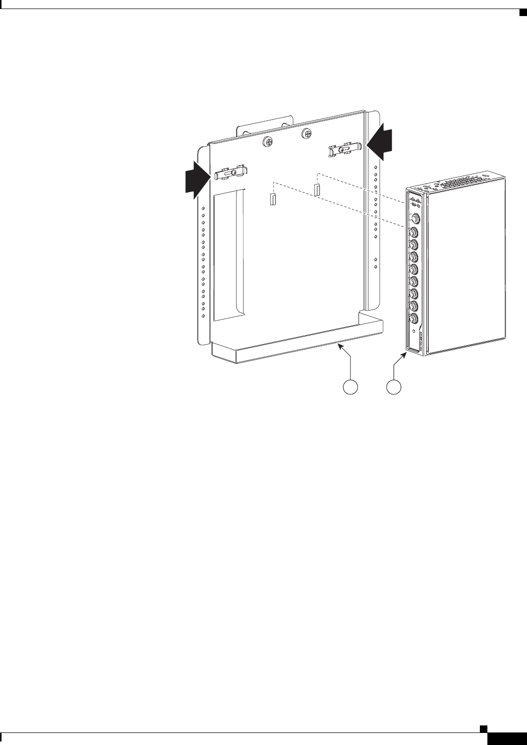
8-15
Cisco TelePresence System 3200
OL-14521-01
Chapter 8 Assembling the Remaining Cisco TelePresence Elements
Parts List
Step 12 Attach the audio/video extension unit to its bracket.
Figure 8-12 Audio/Video Expansion Unit and Bracket
204183
21
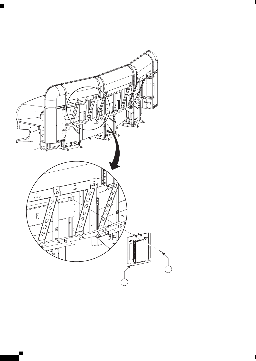
8-16
Cisco TelePresence System 3200
OL-14521-01
Chapter 8 Assembling the Remaining Cisco TelePresence Elements
Parts List
Step 13 Attach the audio/video extension unit to the rear of the display assembly.
Figure 8-13 Audio/Video Extension Unit
35
1
204147
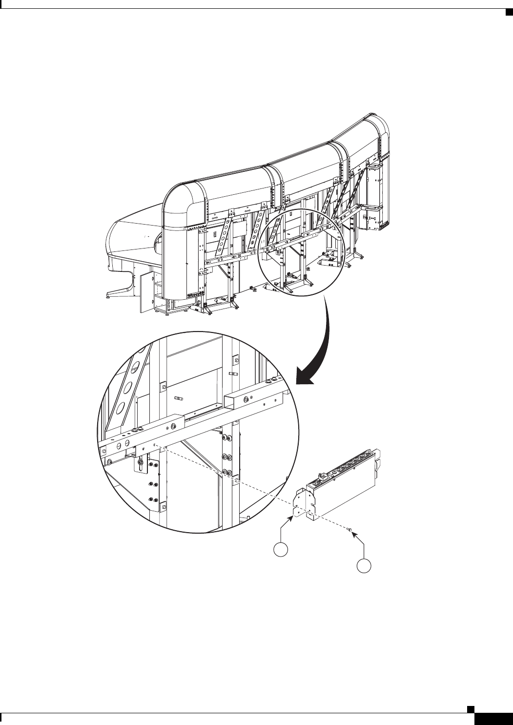
8-17
Cisco TelePresence System 3200
OL-14521-01
Chapter 8 Assembling the Remaining Cisco TelePresence Elements
Parts List
Step 14 Attach the auxiliary control unit to its bracket using 5 mm screws; then, attach the unit and bracket to
the rear of the display assembly.
Figure 8-14 Auxiliary Control Unit
1
35
204148
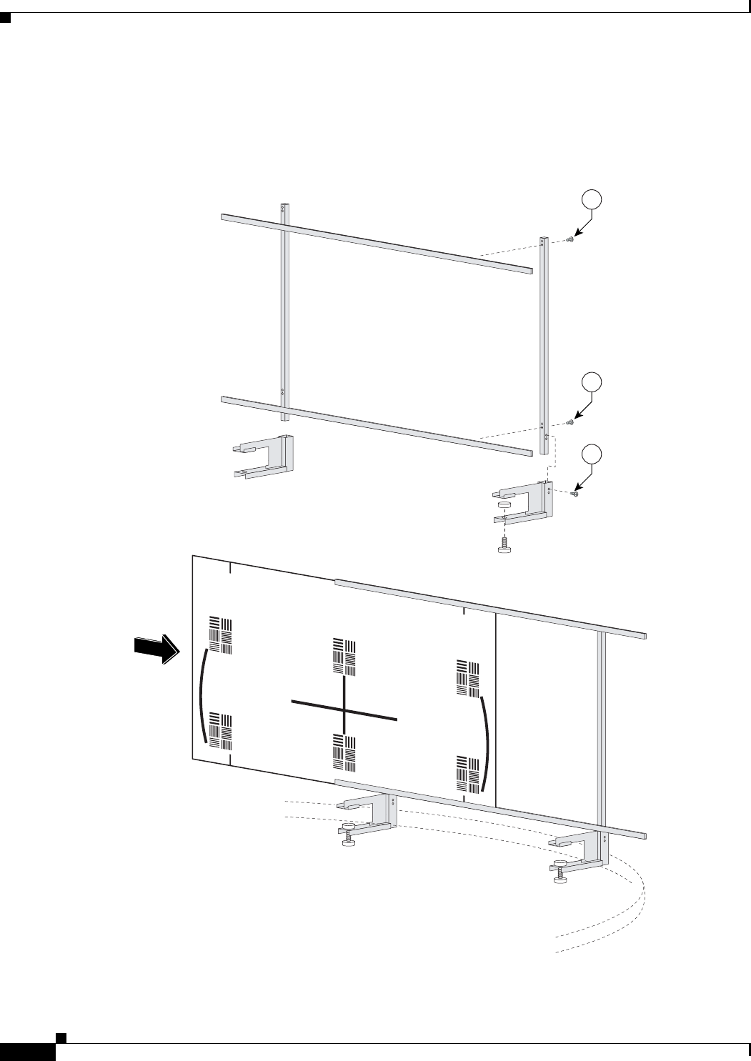
8-18
Cisco TelePresence System 3200
OL-14521-01
Chapter 8 Assembling the Remaining Cisco TelePresence Elements
Parts List
Step 15 Assemble the Large Camera Target.
When you slide the Camera target into the frame, make sure the target is centered in the frame between
the vertical lines at the top and bottom of the target.
Figure 8-15 Camera Target Assembly
6
6
6
201192

CHAPTER
9-1
Cisco TelePresence System 3200
OL-14521-01
9
Routing Power and Signal Cables
Revised: July 28, 2008, OL-14521-01
Parts List
Caution Do not power on the PDUs until all the cables are routed and connected.
Warning
Overcurrent protection is provided by branch circuit protection rated 20A.
Key Part Description Part Number Qty Ctn Notes
1Power distribution units 74-4787-01 4 1
2Speaker cable 37-0849-01 3 1
38 m DVI-to-VGA + audio cable 37-0848-01 1 1
46 m video cable 37-0854-01 2 1
53 m (black) Cat5 Ethernet cable 37-887-01 5 1
610 m Cat6 Ethernet cable, blue 37-0901-01 2 1
77 m power cord 37-xxxx-xx 1 Refer to “Appendix B: Region- and
Country-Specific Equipment” for
specific part numbers
83 m Jumper cord 37-0833-01 9 1
92 m Jumper cord 37-0852-01 1 1 Used for projector.
10 3 m Video-to-DVI cable 37-0853-01 3 1
11 Cable identification stickers 51-4582-01 3 1
12 Cable ties 51-4536-01 75 1
13 Cable tie holders 51-0609-01 75 1
14 Ferrite Core 36-0244-01 6 1
15 Tie wrap for ferrite core 51-1152-01 6 1

9-2
Cisco TelePresence System 3200
OL-14521-01
Chapter 9 Routing Power and Signal Cables
Parts List
Warning
Output receptacles cannot exceed 15A for any one receptacle.
Caution Correct routing of the various power cords to the appropriate PDU is critical for the safety and success
of the Cisco TelePresence System 3200 assembly. Each PDU is routed to a different 20A circuit to
prevent circuit overload when all the electrical components are properly installed. PDUs should be
plugged into their correct wall receptacles as required in the following table.
Note For cable routing for the second row table, see Chapter 7, “Building the Second Row Table Assembly.”
Left PDU 1
(Located on Left Accessory Cabinet.)
Left 20A AC wall outlet
Left PDU 2
(Located on Left Accessory Cabinet.)
Center left 20A AC wall outlet
Right PDU
(Located on Right Accessory Cabinet.)
Center right 20A AC wall outlet
First Row Table PDU
(Located above the projector under the Center
table segment.)
Right 20A AC wall outlet
Second Row Table left-center PDU 20A AC wall outlet
Second Row Table right-center PDU 20A AC wall outlet
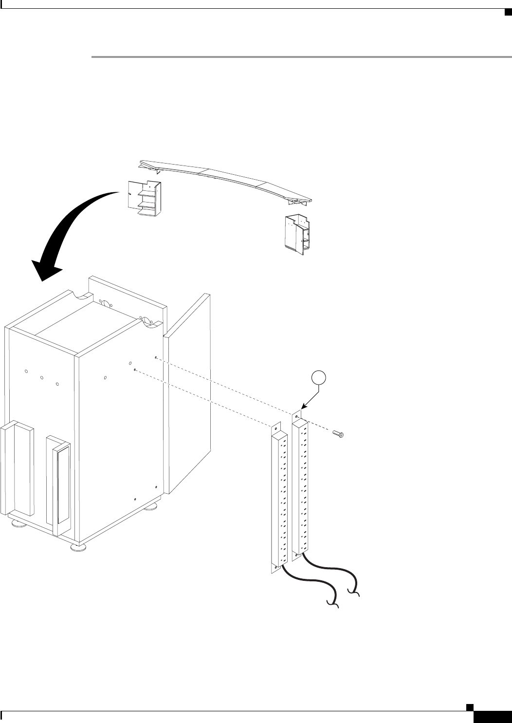
9-3
Cisco TelePresence System 3200
OL-14521-01
Chapter 9 Routing Power and Signal Cables
Parts List
Step 1 Attach the two left Power Distribution Units (PDU) to the left Accessory cabinet.
The accessory cabinets each have screw holes for two PDUs on one side wall and screw holes for one
PDU on the other. When the cabinets are correctly oriented with each door opening out to the side, the
right cabinet has the single-PDU side facing the rear wall, and the left cabinet has the double-PDU side
facing the rear wall.
Figure 9-1 Dual PDU installation to left accessory cabinet
201182
1
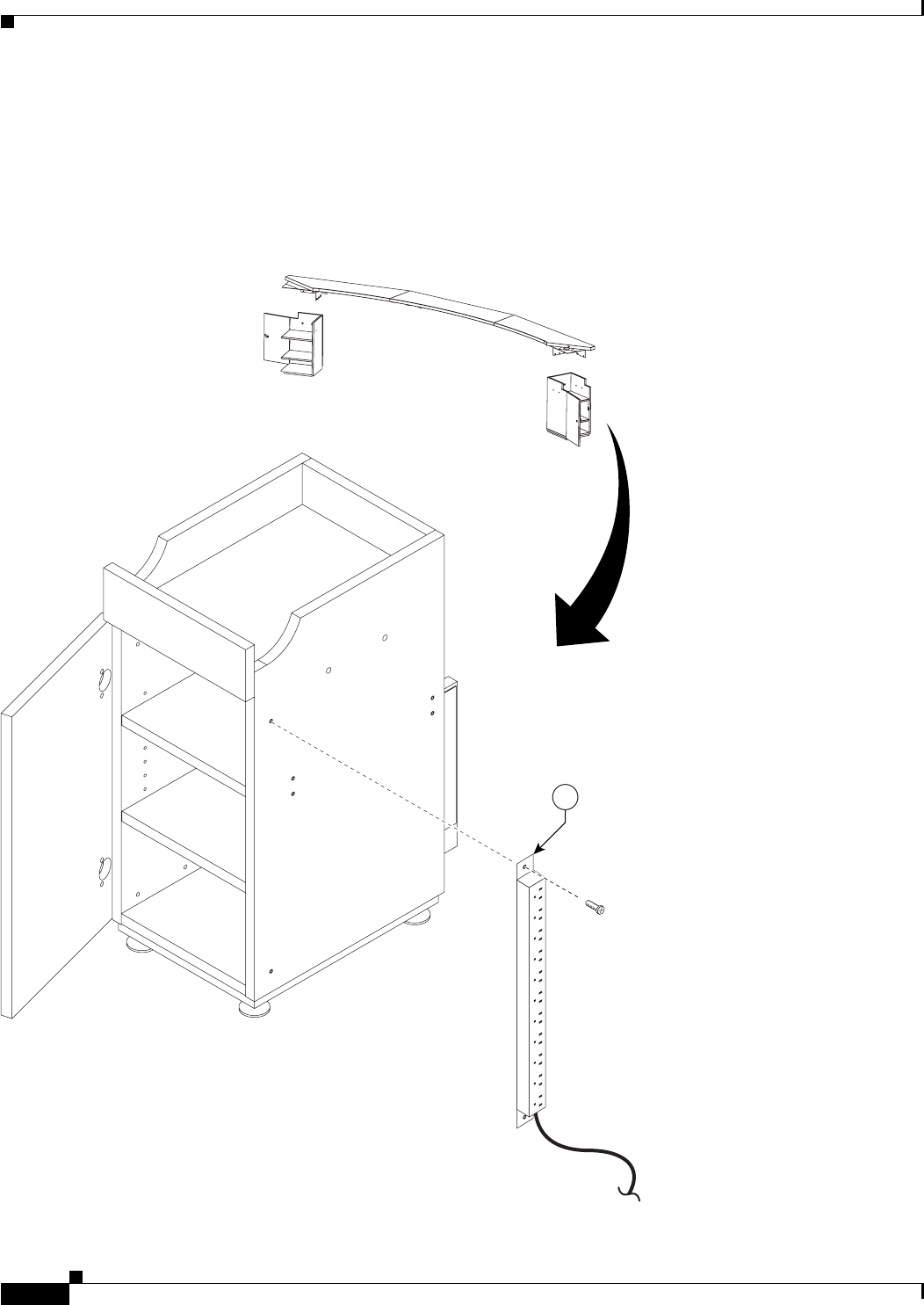
9-4
Cisco TelePresence System 3200
OL-14521-01
Chapter 9 Routing Power and Signal Cables
Parts List
Step 2 Attach the right PDU to the right Accessory cabinet.
The accessory cabinets each have screw holes for two PDUs on one side wall and screw holes for one
PDU on the other. When the cabinets are correctly oriented with each door opening out to the side, the
right cabinet has the single-PDU side facing the rear wall, and the left cabinet has the double-PDU side
facing the rear wall.
Figure 9-2 right side PDU installation to right accessory cabinet
1
201183
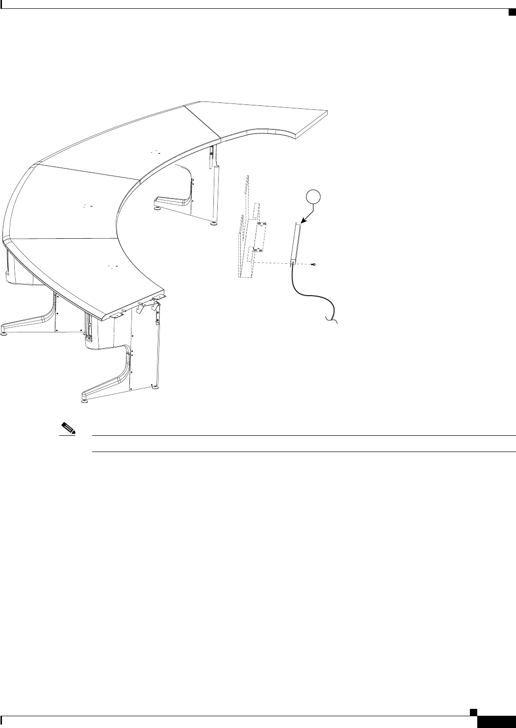
9-5
Cisco TelePresence System 3200
OL-14521-01
Chapter 9 Routing Power and Signal Cables
Parts List
Step 3 Attach the table assembly PDU attachment to the center privacy panel.
Figure 9-3 Table assembly PDU attachment to the center Privacy panel
Note The PDU power cable should extend from the right side.
1
201184
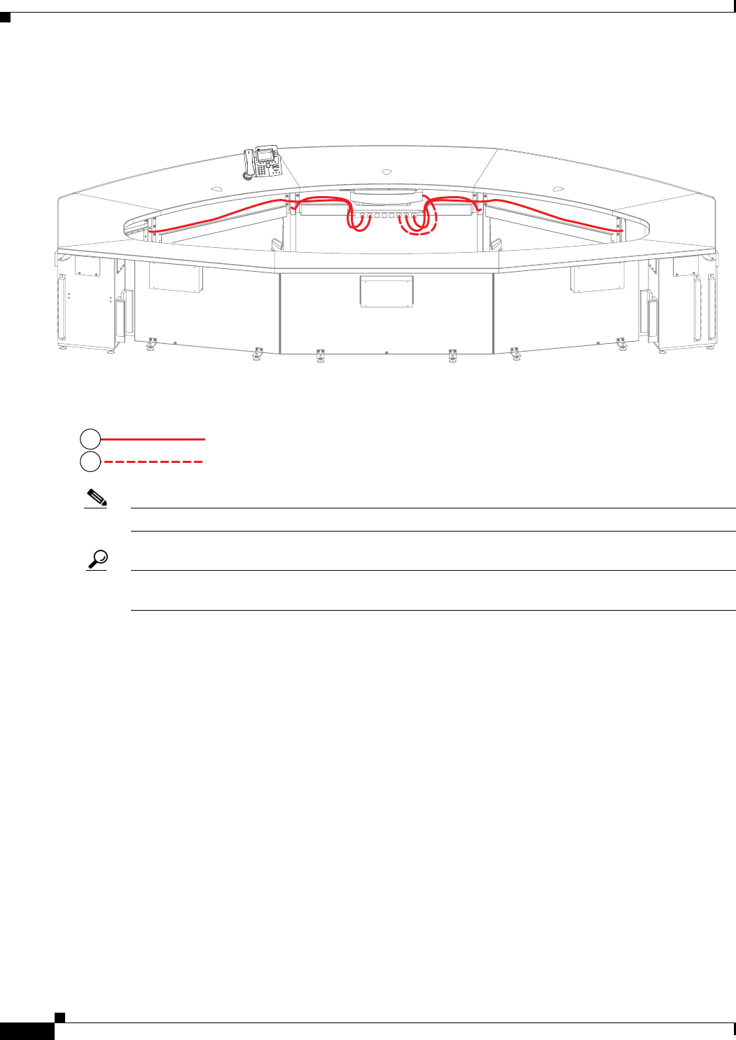
9-6
Cisco TelePresence System 3200
OL-14521-01
Chapter 9 Routing Power and Signal Cables
Parts List
Step 4 Route the power cables for the first row table assembly.
Figure 9-4 First Row Table Assembly Cable Routing
Note The six jumper cords from the I/O modules in the table legs route to the center PDU.
Tip Before plugging the Table leg jumper cords into the Table PDU, label each one. For example, Outer Left
Power, Inner Right Power.
201204
T
elePresence
3
DEF
6
MNO
9
WXYZ
#
2
ABC
5
JKL
8
TUV
0
OPER
1
4
GHI
7
PQRS
CISCO IP PHONE
7970
Table Leg Power
Projector Power
8
9
9-7
Cisco TelePresence System 3200
OL-14521-01
Chapter 9 Routing Power and Signal Cables
Parts List
Step 5 Route the signal cables for the first row microphones, Cisco Unified IP Phone, and (if required) Ethernet
connections in the first row table.
Figure 9-5 Table assembly Signal Cable Routing
Note The Table Leg Signal cables are routed behind the Display structure, along with the other signal cables,
but do not plug into any Codec.
201191
T
elePresence
3
DEF
6
MNO
9
WXYZ
#
2
ABC
5
JKL
8
TUV
0
OPER
1
4
GHI
7
PQRS
CISCO IP PHONE
7970
Table Leg Signal
IP Phone Signal
Microphone Signal
Projector Signal
VGA Peripheral
5
5
4
3
9-8
Cisco TelePresence System 3200
OL-14521-01
Chapter 9 Routing Power and Signal Cables
Parts List
Step 6 Route the second row microphone cables.
Figure 9-6 Microphone Cable Routing
204156
9-9
Cisco TelePresence System 3200
OL-14521-01
Chapter 9 Routing Power and Signal Cables
Parts List
Step 7 If your installation uses wired Ethernet for the second row participants, attach the Ethernet cables to the
modules in the foam bumpers and route the Ethernet cables.
Figure 9-7 Ethernet Cable Routing
204157
9-10
Cisco TelePresence System 3200
OL-14521-01
Chapter 9 Routing Power and Signal Cables
Parts List
Step 8 Route the power cables for the second row table.
Figure 9-8 Second Row Table Power Cable Routing
204172
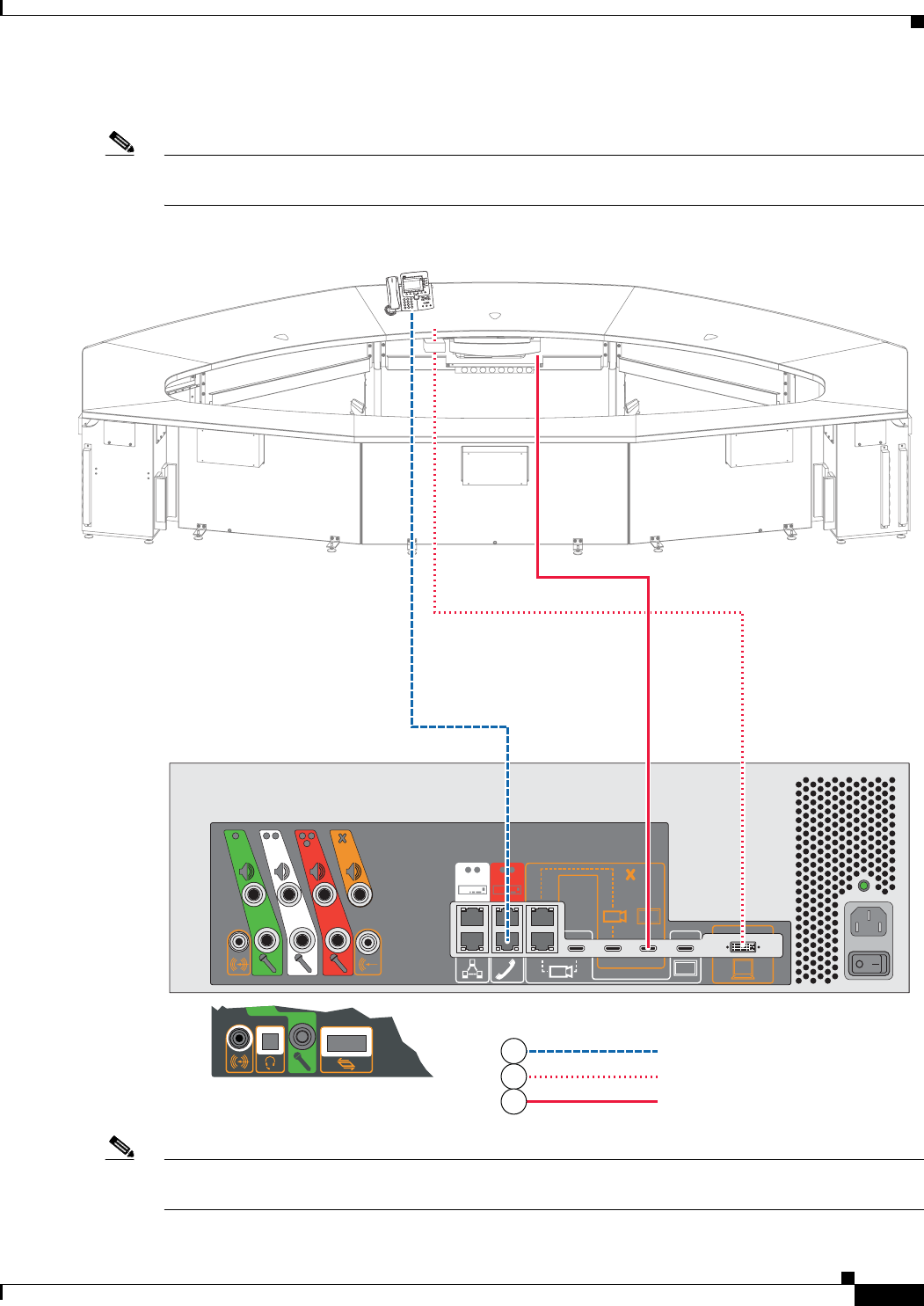
9-11
Cisco TelePresence System 3200
OL-14521-01
Chapter 9 Routing Power and Signal Cables
Parts List
Step 9 Connect the Cisco Unified IP Phone, VGA peripheral, and projector HD video cables.
Note The VGA Peripheral cable is the free-hanging cable resting in the VGA module attached to the center
Table segment.
Figure 9-9 Cabling the Cisco Unified IP Phone, DVI-to-VGA, and Projector HD Video Cables
Note The VGA Peripheral cable is the free-hanging cable resting in the VGA module attached to the center
Table segment.
IP Phone Signal
VGA Peripheral
Projector HD Video to Codec
204168
TelePresence
3
DEF
6
MNO
9
WXYZ
#
2
ABC
5
JKL
8
TUV
0
OPER
1
4
GHI
7
PQRS
CISCO IP PHONE
7970
6
4
2
Other Possible Configuration
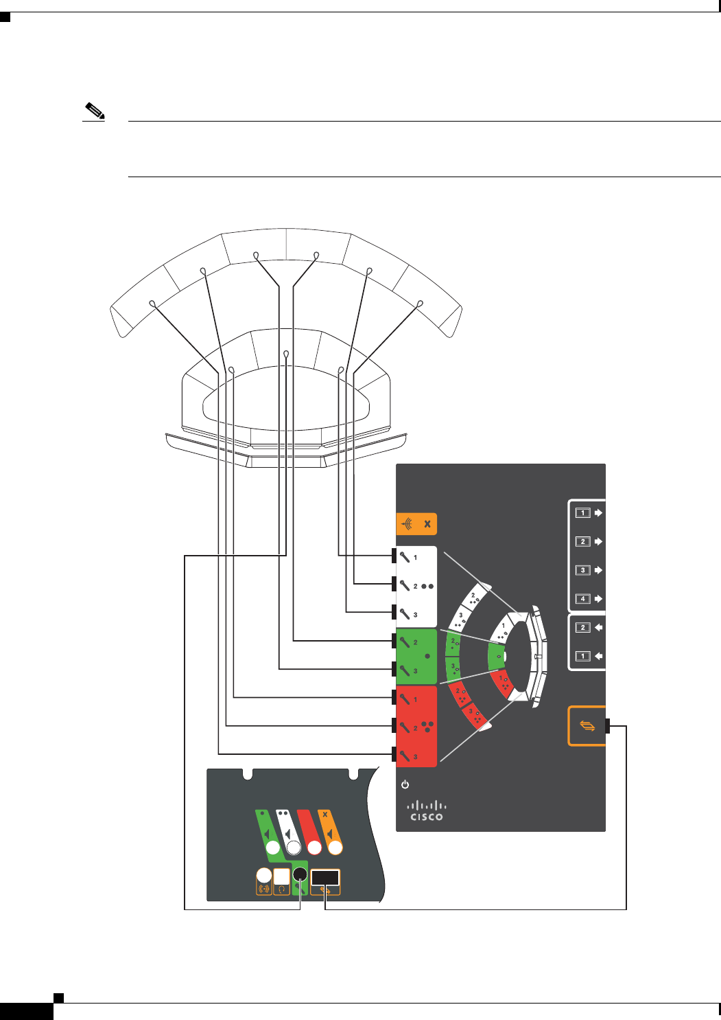
9-12
Cisco TelePresence System 3200
OL-14521-01
Chapter 9 Routing Power and Signal Cables
Parts List
Step 10 Attach the microphone cables to the audio/video extension unit.
Note If you have a Reduced Configuration for your second row table (four tabletops instead of six), use the
same connections, but omit the connections (white connection 2 and red connection 3) for the two outer
table tops.
Figure 9-10 Cabling the Microphones
204162
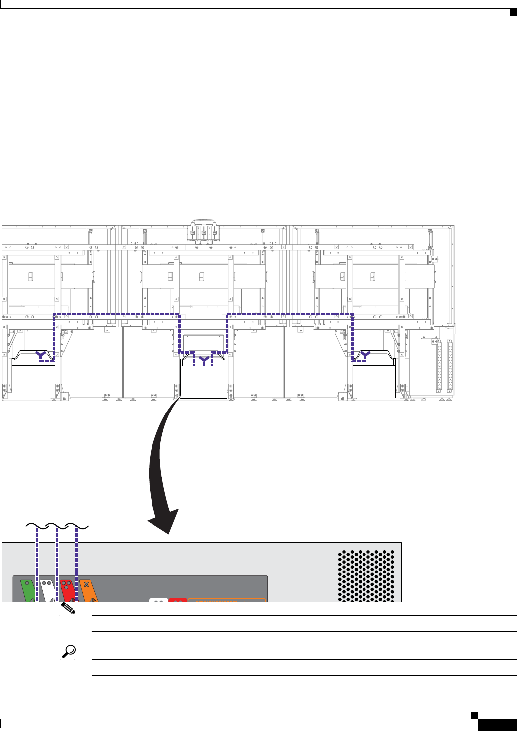
9-13
Cisco TelePresence System 3200
OL-14521-01
Chapter 9 Routing Power and Signal Cables
Parts List
Step 11 Attach and route the cables for the speakers.
Figure 9-11 Cabling the Speakers
Note Figure 9-11 displays the rear view of the Cisco TelePresence System 3200. Left and right are reversed.
Tip Before plugging cables into the Codec, label each one. For example, Left Speaker, Center Speaker.
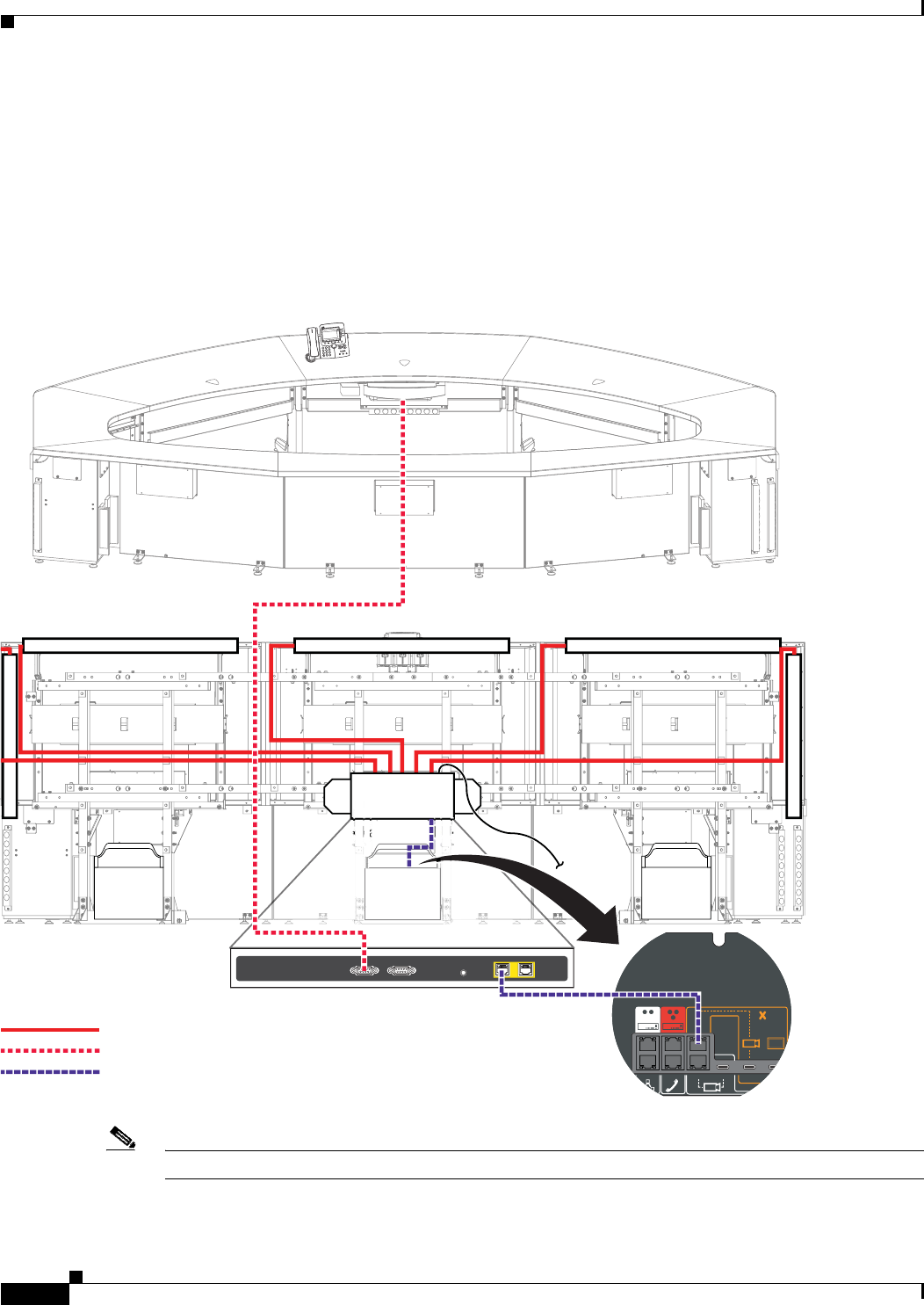
9-14
Cisco TelePresence System 3200
OL-14521-01
Chapter 9 Routing Power and Signal Cables
Parts List
Step 12 Connect the following cables:
• Attach and route the power cables for the lighting assembly by connecting the lights to the auxiliary
control unit.
• Connect the serial cable between the projector and the auxiliary control unit.
• Connect the Ethernet cables between the codec and the auxiliary control unit.
• Connect the power cord for the auxiliary control unit to a wall outlet.
Figure 9-12 Cabling the Lighting Assembly Power Cables and Auxiliary Control Unit-to-Projector Serial Cable
Note Figure 9-12 displays the rear view of the Cisco TelePresence System 3200. Left and right are reversed.
Primary Codec
12 12
10/100 NETWORK POR TSRESETSERIAL PORTS
TelePresence
3
DEF
6
MNO
9
WXYZ
#
2
ABC
5
JKL
8
TUV
0
OPER
1
4
GHI
7
PQRS
CISCO IP PHONE
7970
Power
Projector
204158
RJ45 Ethernet
Auxiliary Control Unit
Auxiliary Control Unit
Auxiliary Control Unit
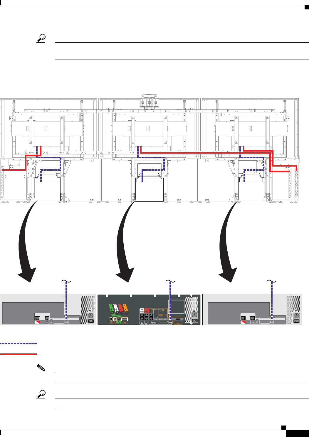
9-15
Cisco TelePresence System 3200
OL-14521-01
Chapter 9 Routing Power and Signal Cables
Parts List
Tip Before plugging the Light fixture power cables into the unit, label each one. For example, 5’ Left light,
4’ Right light.
Step 13 Attach and route the power and signal cables for the plasma displays.
Figure 9-13 Cabling the Plasma Display
Note Figure 9-13 displays the rear view of the Cisco TelePresence System 3200. Left and right are reversed.
Tip Before you plug cables into a Codec or PDU, label each cable.
Signal
Power
201164
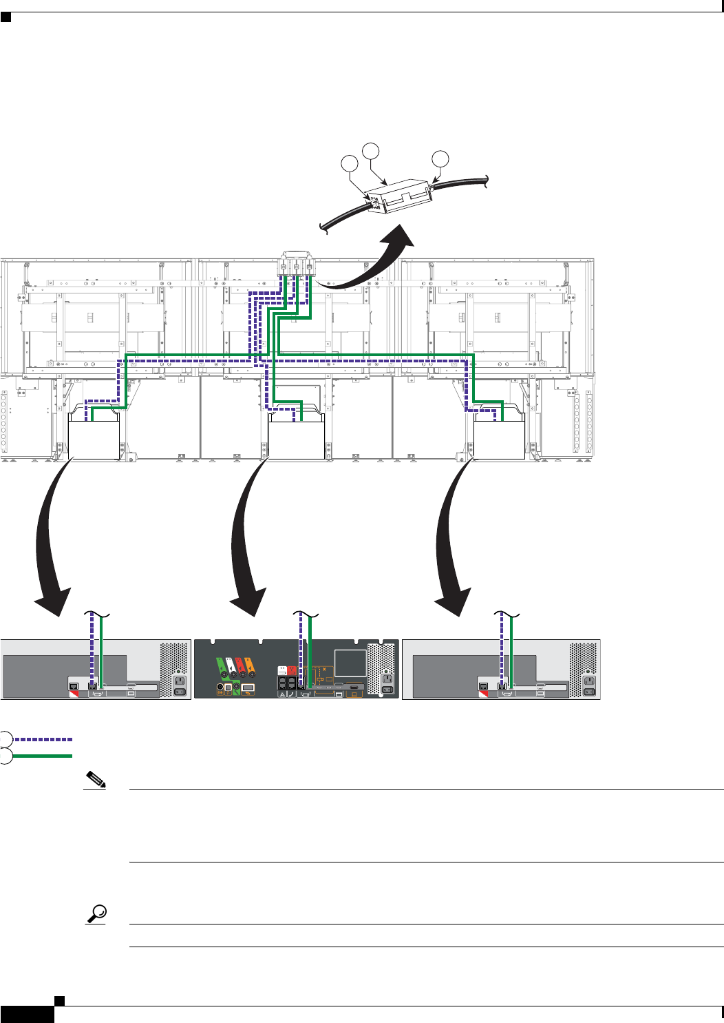
9-16
Cisco TelePresence System 3200
OL-14521-01
Chapter 9 Routing Power and Signal Cables
Parts List
Step 14 Attach and route the power-over-Ethernet and HD Video cables for the camera.
Figure 9-14 Cabling the Camera Assembly
Note The camera cluster can experience radio frequency interference issues if the camera Ethernet and
HD Video cables are routed, bundled, or tied together. Cisco recommends that you route the Ethernet
and HD Video cables separately and use cable ties to tie them to opposite sides of the frame. In addition,
attach the ferrite core and use tie wraps to secure them as shown in Figure 9-14.
Figure 9-14 displays the rear view of the Cisco TelePresence System 3200. Left and right are reversed.
Tip Before you plug cables into a codec, label each cable.
RJ45 Power over Ethernet
HDMI connector
204165
1
0
5
14 15
15
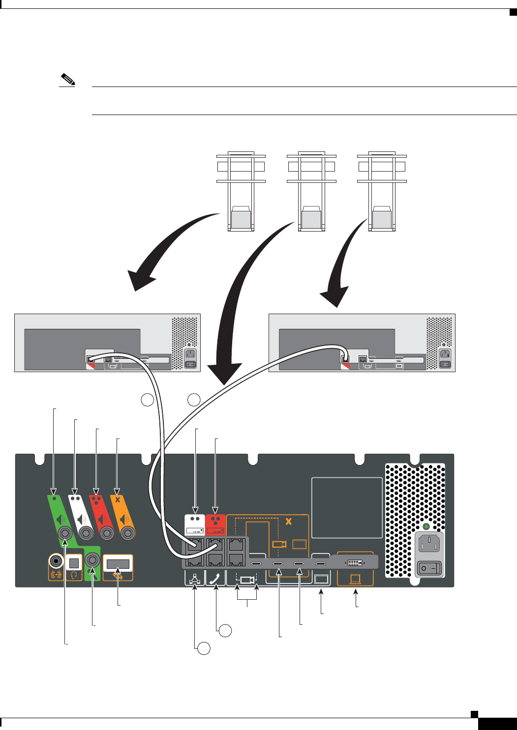
9-17
Cisco TelePresence System 3200
OL-14521-01
Chapter 9 Routing Power and Signal Cables
Parts List
Step 15 Attach the cables between the codecs.
Note If you ordered a Presentation Codec with your TelePresence system, refer to the Cisco TelePresence
Hardware Options and Upgrade Guide for cabling instructions for the presentation codec.
Figure 9-15 Inter-Codec Cabling
5 5
6
6
204166
Auxiliery Video Out
Camera
IP Phone
Network
Left
Right
Auxilliary
Audio
Expansion Unit
Document Camera
Left Codec
Right Codec
Center
Display Auxiliery Video In
First Row Center
Microphone
Speaker
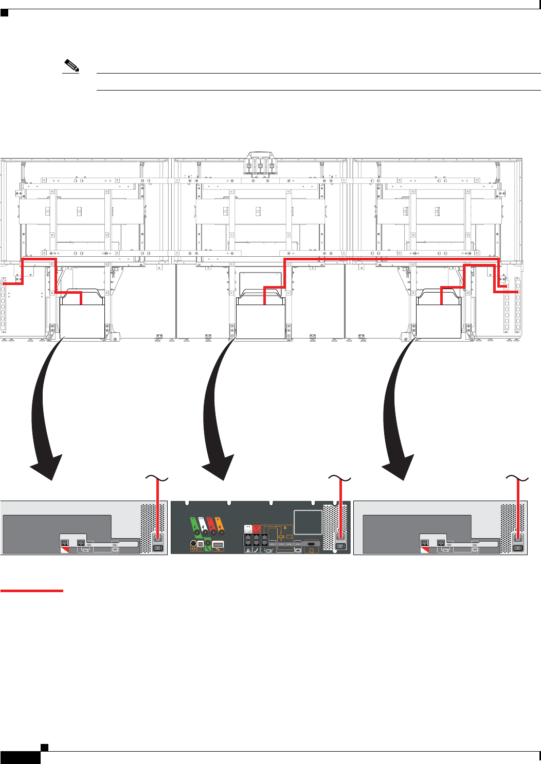
9-19
Cisco TelePresence System 3200
OL-14521-01
Chapter 9 Routing Power and Signal Cables
Parts List
Step 17 (Optional) If your installation uses an optional external display or a document camera, install and route
the cabling.
Figure 9-17 Cabling Diagram: CTS-3200 Installations with an External Display and Document Camera
205784
12 12
10/100 NETWORK POR TSRESETSERIAL PORTS
Document
Camera
Signal
Document
Camera
Video Out
Primary Codec
Audio/
Video
Expansion
Unit
Projector
External Display
(Optional)
Document
Camera
(Optional)
Auxiliary Video Out
Camera
IP Phone
Auxiliary
network
port
Network
Left Right
First Row
Center Microphone
Document Camera
Video In
Left Codec
Right Codec
Center
Display Auxiliary Video In
Video In
Video
In
Video
Out
Video
In
Audio Expansion
Unit
Speaker
Auxiliary Control Unit
Serial 2
Serial 1
Ethernet 1
Ethernet 2
Serial
Other Possible Configuration
9-20
Cisco TelePresence System 3200
OL-14521-01
Chapter 9 Routing Power and Signal Cables
Parts List
Step 18 (Optional) If your installation uses an external display or a document camera with a presentation codec,
install and route the cabling.
Refer to the “Options for the Cisco TelePresence System 3200” chapter of the Cisco TelePresence
Hardware Options and Upgrade Guide for more information about the presentation codec.
Figure 9-18 Cabling Diagram: CTS-3200 Installations with a Presentation Codec, External Display and Document
Camera
205783
12 12
10/100 NETWORK POR TSRESETSERIAL PORTS
Document
Camera
Signal
Document
Camera
Video Out
Primary Codec
Audio/
Video
Expansion
Unit
Projector
External Display
(Optional)
Document
Camera
(Optional)
Presentation Codec
Auxiliary Video Out
Camera
IP Phone
Auxiliary
network
port
Network
Left Right
First Row
Center Microphone
Document Camera
Video In
Left Codec
Right Codec
Center
Display Auxiliary Video In
Document Camera Signal
Auxiliary Video In
Video Out
Video In
Video
In
Video
Out
Video
In
Audio Expansion
Unit
Speaker
Auxiliary Control Unit
Serial 2
Serial 1
Ethernet 1
Ethernet 2
Serial
Signal
Other Possible Configuration

9-21
Cisco TelePresence System 3200
OL-14521-01
Chapter 9 Routing Power and Signal Cables
Parts List

9-22
Cisco TelePresence System 3200
OL-14521-01
Chapter 9 Routing Power and Signal Cables
Parts List

CHAPTER
10-1
Cisco TelePresence System 3200
OL-14521-01
10
First-Time Setup
Revised: February 6, 2009, OL-14521-01
After you have assembled the Cisco TelePresence System (CTS), you set up the individual system
components (such as displays and cameras) using Hardware Setup, located under Troubleshooting in
the CTS Administration software. This chapter explains how to initially set up CTS components and
contains the following sections:
• Loading CTS Administration Software, page 10-1
• Setting Up CTS Components, page 10-4
Note You cannot perform diagnostics during an active Cisco TelePresence system call.
Parts List
Loading CTS Administration Software
CTS Administration Software is factory-installed on each codec and loads during initial bootup.
To load CTS Administration Software:
Step 1 Turn on the Auxiliary Control Unit.
Step 2 Power on the three PDUs in that are located on the accessory cabinets and the single PDU that is
underneath the first row table (near the projector).
Key Part Description Part Number Qty Ctn Notes
Camera Hood Assembly (Figure 10-7)
1Camera assembly 800-30872-01
68-3277-01
1 2
2Camera hood cover: top 1 2
3Camera hood cover: bottom 1 2
7M4 x 12mm Pan Head screws, black 48-2426-01 2N/A
10-2
Cisco TelePresence System 3200
OL-14521-01
Chapter 10 First-Time Setup
Loading CTS Administration Software
Note Make sure that you power on all codecs within 30 seconds to avoid power on detection failure.
After you turn on the codecs, the displays associated with each codec becomes active. CTS displays
green check marks on all displays to show bootup progress. Bootup is complete when the system
displays six check marks as shown in Figure 10-1.
Figure 10-1 Bootup Completed
Note If the last check mark displayed is a red “X,” there has been a compact flash error. Please contact Cisco
Technical Support.
After bootup completes, make a note of the IP address that displays on the center of the screen as shown
in Figure 10-2. You use that information to log in to the Cisco TelePresence System Administration. This
IP address displays until you log in to Cisco TelePresence System Administration or use Secure Shell
(SSH) to log in to the CTS-3000.

10-3
Cisco TelePresence System 3200
OL-14521-01
Chapter 10 First-Time Setup
Loading CTS Administration Software
Figure 10-2 System IP Address
Note Note If the IP address that displays is 192.168.100.2, the CTS-3200 could not contact the DHCP server
or your system does not use DHCP. If your network does not use DHCP, navigate to Configuration >
IP Settings, change the DHCP Enabled setting to No, and specify a static IP address, subnet mask,
gateway and DNS server.
Step 3 After successful bootup, the CTS Administration Software loads. When CTS Administration Software
loading is complete, the Cisco IP telephone displays a welcome message, which displays the IP address
from which you will be able to access the CTS Administration software. The welcome screen only
appears the first time the system is booted up after initial installation or after a factory reset.
Note The telephone will not be registered at this time. It will show a directory number of 7000 but the
telephone will not function as a telephone at this time.
Step 4 Make a note of the IP address that appears on the display. You use this IP address to log in to the Cisco
TelePresence System administration console.
Step 5 If you have not already done so, configure the your Cisco Unified IP Phone in the
Cisco Unified Communications Manager IP Phone Device page. For detailed instructions to configure
Cisco Unified Communications Manager for use with your CTS-3200, refer to the
Cisco Unified Communications Manager Installation Guide for the Cisco TelePresence System for your
software release.

10-4
Cisco TelePresence System 3200
OL-14521-01
Chapter 10 First-Time Setup
Configuring an Alternate TFTP Server (Optional)
Step 6 From the Cisco IP telephone welcome page, press Next. The system reboots.
Note The system might reboot several times during the initial startup process.
Step 7 Open a browser on a computer that is connected to the network.
Step 8 In the URL field, type the IP address that you obtained in Step 4 and press Enter. The browser launches
Cisco TelePresence System Administration.
Note If you need to obtain the IP address, complete the following steps:
a. On the IP phone, locate Manual at the bottom of the screen and press the Manual soft key.
Note If you cannot locate the Manual button, proceed to Step b.
b. Locate Info at the bottom of the screen and press the Info soft key.
c. Scroll down to the IP Address listing and copy the address.
Step 9 Log in to the system by entering the following information:
Step 10 Log in using the following:
–
Username: admin (case sensitive)
–
Password: cisco (case sensitive)
Configuring an Alternate TFTP Server (Optional)
If you need to use an alternative TFTP server, configure the parameters for the alternative TFTP server
and related Cisco IP phone parameters in Unified CM in the Cisco Unified Communications Manager
IP Phone Device page. For instructions to configure an alternate TFTP server, refer to the “Configuring
the Cisco TelePresence System” chapter of the Cisco TelePresence System Administrator's Guide for
your software release.
Note If you are using the TFTP address that DHCP supplies for Cisco Unified Communications Manager, do
not perform this step.
Setting Up CTS Components
To set up the CTS components:

10-5
Cisco TelePresence System 3200
OL-14521-01
Chapter 10 First-Time Setup
Setting Up CTS Components
Step 1 Using the IP address displayed in the Cisco IP telephone welcome message, log in to the CTS
Administration software.
Step 2 From Troubleshooting, choose Hardware Setup to initially set up the components in the
Cisco TelePresence system. Cisco suggests that you set up CTS components in the following order:
• Setting Up the Displays, page 10-5
• Setting Up the Cameras, page 10-6
• Setting Up the Speakers, page 10-13
• Setting Up the Microphones, page 10-13
• Setting Up the Projector, page 10-14
• Other Devices, page 10-18
Setting Up the Displays
A display is set up correctly when the color on the display has been adjusted for the lighting in the
meeting room. Each display must be set up individually.
• From the Hardware Setup page under Troubleshooting, click the Display radio button.
• Click Start to begin the adjustment process.
Each display in the meeting room should now be showing a set of horizontal grey bars and that display's
relative position. Select the color temperature of the lighting in the meeting room and click Apply.
Selecting the Light Level
When adjusting the images on the display screens for the Cisco TelePresence system, you must take the
color temperature of the ambient light in the room into consideration.
Sources of light in most rooms are either incandescent light bulbs that use tungsten filaments or
fluorescent lights. Each of these light sources, and the amount of light in terms of lumens or watts,
produces a different color temperature. This color temperature is sometimes expressed using terms such
cool, warm, or daylight, but can be expressed more precisely in kelvins (K) as a numeric value.
Following are the temperatures that can be selected for adjusting the image on the Cisco TelePresence
display screens:
• 3500 K
• 4000 to 4100 K (recommended setting)
• 5000 K
• 6500 K
• 7500 K
In many cases, the color temperature is printed on the light bulb. If you are unable to ascertain the type
and color temperature of light bulbs in the meeting room, experiment with color temperature settings
until the color and images on the display screen look lifelike.

10-6
Cisco TelePresence System 3200
OL-14521-01
Chapter 10 First-Time Setup
Setting Up CTS Components
Troubleshooting Displays
Use Table 10-1 to troubleshoot problems with the images on the displays.
Setting Up the Cameras
The cameras are set up correctly when images are centered and in focus on the display screens and the
white balance has been configured. The hardware setup software provides a camera Auto Adjust feature
and a way to use targets to fine-tune the camera’s focus.
Ta b l e 10-1 Troubleshooting Chart for Display Problems
Problem Possible Cause Action
Cisco TelePresence 3000/3200
only
Power-on test indicates the
displays turn on in the
wrong sequence. The
normal power on sequence
is the left, center, then right
display screen.
Video cable is not connected to its
corresponding codec connector.
Ethernet cable from secondary
codec is not plugged into the
correct port on the primary codec.
Check that the cable from each
display is plugged into the correct
connector on its corresponding
codec.
Plug the HD Video-to-HD Video
cable into the display connector on
the correct codec, as follows.
• Plug the center display into the
primary codec.
• Plug the participant’s left
display into the left secondary
codec.
• Plug the participant’s right
display into the right
secondary codec.
No image. Power cable is not plugged in.
Power switch on the back of the
display is off.
Check power connections and
switches on each display.
No image. The display has no image when
you are between calls.
No image expected. Enable a
display test from the Web user
interface to place the displays in
test mode.
No image. Video cable is not connected. (CTS-1000 only) Check that the
LED is lit at the bottom front of
each display and is either green or
amber.
Contact Cisco technical support if
you are certain that the cabling is
correct and power is applied to the
system, but no image is seen on the
display.

10-7
Cisco TelePresence System 3200
OL-14521-01
Chapter 10 First-Time Setup
Setting Up CTS Components
Attach the Camera Targets
Two camera targets are provided with the Cisco TelePresence system: a large white target and a smaller
target. You attach the large white target to the table prior to performing Auto Adjust (white balancing).
Attach the large Camera target to the corresponding Table segment, with the clamps matching the
counterbore feature under the table. Center the target on the edge of the table and standing vertical with
the clamps underneath the table holding it tight. The target pattern should face the camera.
Start the Software Setup
• From the Hardware Setup page under Troubleshooting, click the Camera radio button.
• Click Start to begin the camera setup. You should see output from each camera in the appropriate
camera display area.
• Click Setup under the image of a display screen to begin adjustments for the camera focused on that
screen.
If you need further information about testing or adjusting this device, click Help in the content area or
see the troubleshooting charts in this section.
Note Make sure that the table edge is between the hash marks on both sides of the display.
Auto Adjust
• After attaching the large white camera target to the table, click Auto Adjust.
This action allows software to adjust the camera settings automatically. You will see various images
and colors on the displays during the adjustment. Auto Adjust takes approximately 20 seconds.
Align the Camera
• Click Show Camera Target.
• Using the zoom ring on the camera lens, and the left/right, up/down, and rotation adjustment screws
on the camera, perform the following adjustments:
–
Make manual adjustments to the camera focused on the target to align the red plus sign to the
center plus sign on the target.
–
For the center display, zoom and align the camera so that the curved lines on each side of the
target touches the sides of the display.
–
For the left display, zoom and align the camera so that the curved line on the right side of the
display touches the red adjustment line at the right edge of the display to corresponding lines
on the target. On both sides of the display, you will see two small red hash marks. Adjust the
camera so that the edge of the table is positioned vertically exactly between the hash marks on
either side of the display.
See Figure 10-3 for the location of the adjustment screws on the camera. See Figure 10-4,
Figure 10-5, and Figure 10-6 for the correct placement of the curved lines and plus signs on the
camera target.
Note If one of the left/right screws is covered by the camera cable, use the other screw to make all
left/right adjustments.
10-8
Cisco TelePresence System 3200
OL-14521-01
Chapter 10 First-Time Setup
Setting Up CTS Components
Figure 10-3 Camera Mounting Plate
201205
Up/down screw
Left/right screws
Rotation screws
Lens
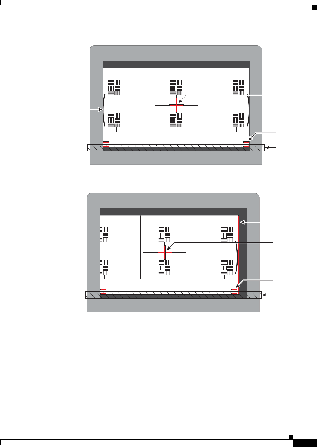
10-9
Cisco TelePresence System 3200
OL-14521-01
Chapter 10 First-Time Setup
Setting Up CTS Components
Figure 10-4 Correct Camera Target Alignment—Center Display
Figure 10-5 Correct Camera Target Alignment—Right Display
Red plus
sign within
black cross
Red lines
Note curved
lines touching
screen border
Table
edge
205764
Red plus
sign within
black cross
Red lines
Table
edge
Red
Vertical line
205765
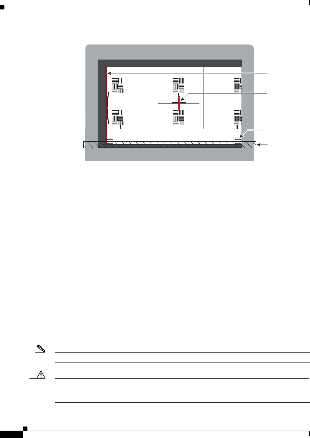
10-10
Cisco TelePresence System 3200
OL-14521-01
Chapter 10 First-Time Setup
Setting Up CTS Components
Figure 10-6 Correct Camera Target Alignment—Left Display
• Click Hide Camera Target to remove the alignment images.
• Click Done when you complete the adjustment.
Show All Camera Targets
• Click Show All Camera Targets to align each camera independent of the other cameras.
Flipping the Video Image
• Click Flip Video on Each Display to display a mirror image—meaning to simulate the image that
attendees will see—for the selected screen(s). Use this feature to make sure all three cameras are
vertically aligned.
Focus the Camera
• Place the small target on the table.
• Click Setup, then click Show Focus Target.
• Adjust the small target so that the green box encloses some of the patterns on the small target.
• Adjust the focus ring on the camera lens so the lines on the target are in focus. The ring is labeled
“N – 8”. The thumbscrew (or 0.9 mm Allen wrench) is used to unlock the focus ring.
• Click Hide Focus Targets, then click Done when you complete the adjustment.
Attaching the Camera Hood Assembly
• After you complete the camera adjustment, attach the camera hood assembly. See Figure 10-7.
Note Attach the top hood before attaching the bottom hood.
Caution Do not overtighten the screws, or use a power screwdriver to tighten the screws. In addition, make sure
that you use screws of the correct length (20 mm). Overtightening the screws, or using a screw that is
too long, can cause the plastic hoods to break.
Red plus
sign within
black cross
Red lines
Table
edge
Red
Vertical line
205766
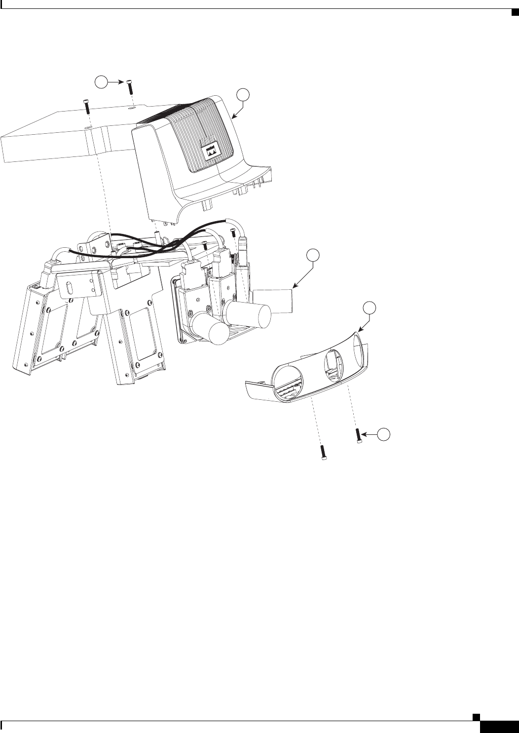

10-12
Cisco TelePresence System 3200
OL-14521-01
Chapter 10 First-Time Setup
Setting Up CTS Components
Ta b l e 10-2 Troubleshooting Chart for Camera Problems
Problem Possible Cause Action
Cisco TelePresence 3000/3200 only
Camera image appears on the
wrong display.
Cables are plugged into the
wrong connector ports.
Check that the cables from each
camera are plugged into the
correct connector on its
respective codec.
Two connections are made for
the camera, an RJ-45 cable plugs
into the large connector and a
video-to-DVI-I cable plugs into
the small connector. Connect
them as follows:
• Plug the center camera into
the primary codec.
• Plug the participant’s left
camera into the left
secondary codec.
• Plug the participant’s right
camera into the right
secondary codec.
Image not positioned correctly. Camera is not aligned correctly. Adjust and focus the camera
using the targets.
Image colors are incorrect. Video cable is only partially
connected.
Color settings are not correct.
Tug on the plug to see if it is
fully plugged in.
See separate documentation for
the camera adjustment
procedures.
No image. Lens cap is in place.
Camera is not plugged in or is
plugged in incorrectly.
Remove the lens cap.
Check power connections and
switches on each display.
Verify that the video and
Ethernet cables from each
camera are plugged into the
correct connectors on their
respective codecs.
No image. Camera or display is broken. Contact Cisco technical support
if you are certain that the cabling
is correct, power is applied, and
a display and camera test has
been run, but no image is seen on
the display.

10-13
Cisco TelePresence System 3200
OL-14521-01
Chapter 10 First-Time Setup
Setting Up CTS Components
Setting Up the Speakers
The speakers are set up correctly you can hear sound clearly from each one. You can choose whether you
want to cycle through the speakers automatically or manually.
• Click Speakers on the Hardware Setup window to select the speaker test.
• Click Start to begin the speaker setup.
• Click Cycle Through Speakers to have sound cycled automatically for 5 seconds on each speaker.
• Click Manually Step Through Speakers to test sound on each speaker. Click Next Speaker to
progress to the next speaker.
Troubleshooting Speakers
Use Table 10-3 to troubleshoot problems with speakers.
Setting Up the Microphones
The microphones are set up correctly when each microphone registers sound. You must supply sound at
each microphone to complete setup.
The Microphone Troubleshooting screen displays the number of microphones available for testing. For
You will see three screens with either two of three microphones per screen, depending on the number of
microphones installed. The top microphone represents the microphone in the front row; the bottom
microphone icons represent the back row microphones.
• Click Microphones on the Hardware Setup window.
• Click Start to begin setup.
• Lightly tap each microphone and watch the audio meter on the corresponding display screen to see
that sound registers.
Ta b l e 10-3 Troubleshooting Chart for Speaker Problems
Problem Possible Cause Possible Solution
No sound is heard. Speaker cable is not connected
or is only partially connected.
Check that the red and black
pronged ends of the speaker
cable are securely fastened under
their corresponding connectors
on the speaker.
Check that the speaker cable is
plugged into the correct receptor
on the primary codec.
Tug on the plug to see if it is
fully plugged in. Press the plug
in firmly until a click is heard.
Cisco TelePresence 3000/3200 only
Sound heard at wrong speaker.
Speaker cable is not connected in
the correct connector.
Check that the speaker cable is
plugged into the correct receptor
on the primary codec. Plug all
speakers into the primary codec.
Sound is not synchronized with
video.
—Contact Cisco technical support.

10-14
Cisco TelePresence System 3200
OL-14521-01
Chapter 10 First-Time Setup
Setting Up CTS Components
• Click Refresh Microphones Status (CTS-3200s only) to update the on/off status of all
microphones.
• Click Stop when setup is complete.
Troubleshooting Microphones
Use Table 10-4 to troubleshoot problems with microphones.
Setting Up the Projector
To set up the projector, complete the following steps:
Note The following procedures are specific to the Sanyo PLV-Z4 and PLV-Z5 projectors.
Ta b l e 10-4 Troubleshooting Chart for Microphone Problems
Problem Possible Cause Possible Solution
Sound is muffled. Something near or on the
microphone is distorting the
sound.
Move objects away from the
microphone.
Cisco TelePresence 3000/3200 only
Sound registers at the wrong
microphone.
Microphone cable is not
connected to its corresponding
codec.
Check that the cable from the
microphone is plugged into the
correct receptor on the codec.
Plug all microphones into the
primary codec.
No sound registers. Microphone cable is not
connected or is only partially
connected.
Check that the system is plugged
in and power is on.
Check that the microphone plug
is firmly seated in the correct
connector on the primary codec.
Check that the mute light on each
microphone is lit. An unlit light
indicates that the microphone is
not plugged in.
Lightly tap the microphone to
see if sound registers.
Contact Cisco technical support
if you are certain that the cabling
is correct and power is applied to
the system, but no sound
registers on the microphone.
Microphone icon with red pipe
displays.
Microphone is not connected. Check that the microphone is
properly plugged in.
Microphone icon with question
mark displays.
One of the microphones is
unplugged.
Check that the microphone is
properly plugged in.

10-15
Cisco TelePresence System 3200
OL-14521-01
Chapter 10 First-Time Setup
Setting Up CTS Components
Step 1 Make sure that a serial cable is connected from your projector to the Serial output of the auxiliary control
unit. See Chapter 9, “Routing Power and Signal Cables” for information about cabling your system with
an Auxiliary Control Unit.
Step 2 Start a test pattern display for the projector by completing the following steps:
a. Open a browser that is connected to the network.
b. Enter the IP address of the primary codec to log in to Cisco TelePresence System Administration.
c. Select Troubleshooting > Hardware Setup, then click the Presentation Devices radio button.
d. Select the Test Pattern radio button.
e. Click Start to begin the test.
Step 3 Turn on the projector by turning the projector power rocker switch to the ON position.
The projector takes approximately 15-30 seconds to warm up, and should be fully initialized within one
minute. If the projector is not receiving video, the screen will be blue. If the projector does not receive
video for five minutes and 30 seconds, the projector turns off.
If the test pattern is displaying correctly, you should see a grid projected on the projection surface. In
the center of the grid, you should see a series of horizontal grey bars. You should also see a one-pixel
wide green border around the outside of the grid.
Step 4 From Cisco TelePresence System Administration, click Set Projector Defaults to automatically
configure the projector for use with the CTS-3200.
Step 5 Set the group, number and data settings by completing the following steps:
Note Changing these settings allows a projector to be monitored by the System Network Management
Protocol (SNMP) when the projector is in an inactive state. If a projector lamp fails, SNMP does not
properly report the failure from an inactive projector until you complete these steps.
Tip Use the projector remote control or press the buttons on the projector to complete these steps.
a. Press the Menu key for 20 seconds.
The letter S displays in the upper left corner of the screen.
b. Press the Screen key for 3 seconds.
The service menu displays.
c. Press OK until the group number setting changes to 100.
d. Press the Down Arrow key until the No. setting changes to 4.
e. Press the Left Arrow key until the Data setting changes to 0.
f. Press the ON-OFF key to end the service menu.
Step 6 Center the projector display within the screen by completing the following steps:
a. Locate the lock switch and two dials on the side of the projector.
b. Move the switch to the unlock position.
c. Rotate the vertical dial to position the top of the image 1 inch below the bottom of the wood surface.
d. Rotate the horizontal dial to position the sides of the image 15 inches from each of the seams on the
table segments.

10-16
Cisco TelePresence System 3200
OL-14521-01
Chapter 10 First-Time Setup
Setting Up CTS Components
Completing this step should center the image in the screen. If the image is not centered, adjust the
image until the distance is equal from each table segment seam.
e. Move the switch to the lock position.
Step 7 Aim the remote control at the lens of the projector.
Tip You can use the screen to reflect the signal back to the projector if you are sitting at the table.
Leave the projector in this state. When the video signal is turned off or disconnected, the projector will
go black for 30 seconds. Then it will count down for 5 minutes and then turn off the lamp.
If a video signal is applied during this 5 minute and 30 second countdown the video will reappear
immediately. If the countdown completes, the projector goes into a cooldown mode which will ignore a
video signal for 30 seconds. It will then stay in a standby mode and will power back up when a video
signal is connected. It will take 15 seconds for the projector to light back up.
Step 8 To check either VGA or document camera input, perform the following steps:
a. Click Presentation Devices on the Hardware Setup window.
b. Perform one of the following steps to test the video input:
• Click the VGA radio button to test input from a VGA device
• Click the Document camera radio button to test input from the document camera
If the input image is displaying correctly, you should see an image projected on the projection surface.
Step 9 If the image is out of focus or is too small, use the projector focus ring to focus the image and use the
zoom lever to create the largest possible image.
Step 10 Click Stop in Cisco TelePresence System Administration to remove the test pattern and complete the
projector test.
Troubleshooting Presentation Devices
Use Table 10-5 to troubleshoot problems with presentation devices.
Ta b l e 10-5 Troubleshooting Chart for Presentation Device Problems
Problem Possible Cause Possible Solution
Test pattern is not displayed. Projector power switch is off. Check projector power switch.
Switch the projector on/off
rocker switch to the ON position.
Test pattern is not displayed. Power cable is not connected. Check to see if the LED on the
top of the projector is
illuminated; it can be either
green or yellow. If the LED light
is not illuminated, make sure that
the power cable is plugged in.

10-17
Cisco TelePresence System 3200
OL-14521-01
Chapter 10 First-Time Setup
Setting Up CTS Components
Note The Cisco TelePresence System can display information from multiple input devices during a meeting;
if multiple input devices are sending information, the projector displays the input from the last
presentation device sending information. If you do not see an image being projected on the screen, try
the following: for VGA devices, unplug the device from the VGA cable, wait 5 seconds, and then plug
the device back in; for document cameras: turn the camera off, wait 5 seconds, and then restart the
device.
Test pattern is not displayed. HD Video cable is not connected
to the projector or to the primary
codec.
Check that the HD Video cable is
plugged into the projector and
into the correct connector on the
primary codec.
Contact Cisco technical support
if you are certain that the cabling
is correct and power is applied to
the system but no image is
displayed.
Test pattern is not displayed. Projector is set up to receive PC
input instead of input from its
HD Video cable connector.
Use the projector remote control
to configure the projector for
HD Video input. If your system
includes an Auxiliary Control
Unit, click Set Projector
Defaults.
Test pattern is not displayed. Object is blocking the path of the
projector.
Remove any objects blocking the
projector lens.
Test pattern is not displayed. Video cable connector is not
securely seated in the projector.
Seat the HD Video cable
connector securely.
Test pattern is not displayed. Video cable connector is not
securely seated in the primary
codec.
Seat the HD Video cable
connector securely.
Test pattern is not displayed. Video cable connector is not
inserted in the correct port on the
primary codec.
Check the cabling diagrams in
“Routing Power and Signal
Cables” chapter of the
Cisco TelePresence System 3200
Assembly, Use & Care, and Field
Replacement Unit Guide to
identify the correct port into
which to insert the HD Video
cable connector. The HD Video
cable connector should be
connected to auxiliary video out.
Table 10-5 Troubleshooting Chart for Presentation Device Problems (continued)
Problem Possible Cause Possible Solution

10-18
Cisco TelePresence System 3200
OL-14521-01
Chapter 10 First-Time Setup
Setting Up CTS Components
Other Devices
Use Other Devices to check the Auxiliary Control Unit, which controls the individual light units
surrounding the displays in CTS conference rooms and enables the CTS to get more complete projector
status information and to restores projector defaults.
• Click Other Devices on the Hardware Setup window.
• Click the Start radio button to access the Auxiliary Control Unit to begin testing. To end the test,
click Stop.
–
Individual light units correspond to the five port numbers of the Auxiliary Control Unit. Click
the appropriate box to select a specific port number; Click Select All to select all ports (and all
light units) or Select None.
–
Click the Refresh On/Off Status button to update the on/off status of each port.
–
Click the Turn Selected Lights On/Off to test the selected light unit(s).
–
Click the Reset Auxiliary Control Unit to power cycle the Auxiliary Control Unit.

CHAPTER
11-1
Cisco TelePresence System 3200
OL-14521-01
11
Use & Care Guide
Revised: July 28, 2008, OL-14521-01
Maintaining the Tabletop
Cleaning your wood surfaces
To avoid the build-up of dirt, dust all wood surfaces on a regular basis. This should be done with a soft,
lint free cloth, slightly moistened with water only. Wipe lightly in the direction of the wood grain and
dry immediately with another cloth. Remember to wipe lightly as dust is abrasive and can cause fine
scratches.
Should a more thorough cleaning become necessary, use a very mild liquid detergent at 1 teaspoon per
quart (5 ml per liter) of lukewarm water. Wipe with a soft, lint free cloth in the direction of the wood
grain. Follow this with a cloth dampened with rinse water and then wipe dry with a third cloth. A quality
glass cleaner could be used as an alternative to the soapy water.
Avoid using waxes or polishes of any kind, especially those containing silicone.
Protecting your wood surfaces
Always use felt backed desk pads and coasters as well as felt pads under your office equipment. Avoid
leaving any plastic materials in one spot on a wood surface for any prolonged periods.
Blot, do not wipe, any liquid spills as soon as possible and follow this with the dusting procedure
mentioned above.
Never expose wood surfaces to extremes of temperature or humidity. Do not place near heaters, vents or
open windows. All natural wood products will change color over time due to exposure to light. Avoid
placing your wood surfaces in direct sunlight and occasionally move the objects on the surface around,
to assist with an even aging of the wood.
Cleaning the Plasma displays
Per industry-standard best practice recommendations for cleaning plasma displays:
The plasma displays require special consideration when cleaning. Wipe the panel surface gently using
only a cleaning cloth or a soft, lint-free cloth. If the surface is particularly dirty, wipe with a soft, lint-free
cloth which has been soaked in pure water or water to which a small amount of neutral detergent has
been added, and then wipe it evenly with a dry cloth of the same type until the surface is dry.

11-2
Cisco TelePresence System 3200
OL-14521-01
Chapter 11 Use & Care Guide
Cleaning the Camera lens
Cleaning the Camera lens
Caution Do not touch the camera after installation is completed. If you need to clean the camera lens, use a dry
microfiber cloth. After cleaning, you will need to realign the camera.
Maintaining the Projector
Note Refer to the Projector User Guide included with your projector for maintenance issues such as cleaning
the projector lens. To replace the projector lamp, see the “Replacing the Projector Lamp—Part Number
CTS-PRJTR-BL-GEN1” section on page 12-17. To replace the projector, see the “Replacing the
Projector—Part Number CTS-PRJTR-GEN1” section on page 12-18.
Warning
Only trained and qualified personnel should be allowed to install, replace, or service this equipment.
Warning
Installation of the equipment must comply with local and national electrical codes.

CHAPTER
12-1
Cisco TelePresence System 3200
OL-14521-01
12
Field-Replaceable Unit Guide
Revised: July 28, 2008, OL-14521-01
This chapter describes the steps you perform to replace the field-replaceable units (FRUs) for the
Cisco TelePresence system and includes the following sections:
• Powering On the System, page 12-1
• Replacing the Camera Cluster—Part Number CTS3K-CAM-CLST-G2, page 12-2
• Replacing a Plasma Display—Part Number CTS-DISP-65-GEN2, page 12-4
• Replacing a Speaker—Part Number CTS-LDSPKR, page 12-8
• Replacing a Codec Unit—Part Number CTS-CODEC-PRI-G2 (Primary Codec) or
CTS-CODEC-SEC (Secondary Codec), page 12-10
• Replacing a Microphone—Part Number CTS-MIC, page 12-12
• Replacing a Light Fixture—Part Number CTS-LIGHT-FIXT, page 12-14
• Replacing the Audio/Video Extension Unit—Part Number CTS-AV-EXP, page 12-15
• Replacing the Auxiliary Control Unit—Part Number CTS-LIGHT-CTRL, page 12-16
• Replacing the Cisco Unified IP Phone—Part Number CP-7975G-CTS, page 12-17
• Replacing the Projector Lamp—Part Number CTS-PRJTR-BL-GEN1, page 12-17
• Replacing the Projector—Part Number CTS-PRJTR-GEN1, page 12-18
• Replacing a PDU—Part Number CTS-PWR-PDU, page 12-19
• Replacing a Display Shelf, page 12-20
• Replacing a First Row Table Top Section, page 12-22
• Replacing a Second Row Table Top Section, page 12-24
Powering On the System
Use this procedure for sections in this chapter that require you to power on the system.
Step 1 If you replaced the primary codec, reconfigure the codec for the new MAC address in
Cisco Unified Communications Manager by performing the following actions:
a. Log in to Cisco Unified Communications Manager.

12-2
Cisco TelePresence System 3200
OL-14521-01
Chapter 12 Field-Replaceable Unit Guide
Replacing the Camera Cluster—Part Number CTS3K-CAM-CLST-G2
b. Change the device MAC address to the MAC address for the new primary codec. The MAC address
should be displayed on the codec.
Step 2 Power on the Cisco TelePresence 3200 by turning the power switches to the On position on the two left
PDUs, single right PDU, and auxiliary control unit.
Six check boxes display on the lower left corner of the center display screen.
Step 3 Wait while the system checks each check box and clears the screen.
The system IP address displays on the lower right corner of the center display screen.
Step 4 Write down the IP address. This is the address of the primary codec.
Step 5 Log in to the system by entering the following information:
a. In the Admin field, type admin.
b. In the Password field, type cisco.
Note If your administrator has changed the user name or password, enter those values.
Step 6 Click Login.
Step 7 Verify the status of the Cisco Unified Communications Manager (seen in the lower left portion of the
window) is Enabled/Up.
Step 8 Select Hardware Setup to verify the cameras, displays, speakers, and microphones are working
properly.
Step 9 If you are replacing a primary codec, perform the following steps:
Note If you are not replacing a primary codec, do not perform the following steps.
a. Navigate to the Device Information > Configuration > CUCM settings window, then perform the
following actions:
b. In the Certificate Trust List (CTL) area, delete the CTL from your system by clicking Delete CTL.
c. In the Use Configuration TFTP Server area, click Automatic to set TFTP conditions to their default
value and remove any alternate TFTP servers.
Replacing the Camera Cluster—Part Number
CTS3K-CAM-CLST-G2
Required Information, Tools, and Equipment
To remove and replace the camera cluster for the Cisco TelePresence 3200, you need the following
information, tools, and equipment:
• Cisco TelePresence System Release 1.4 Administrator’s Guide, OL-13676-03
• Release Notes for Cisco TelePresence System, Release 1.4, OL-12074-05

12-3
Cisco TelePresence System 3200
OL-14521-01
Chapter 12 Field-Replaceable Unit Guide
Replacing the Camera Cluster—Part Number CTS3K-CAM-CLST-G2
• Power screwdriver with 2.5, 3, and 6 mm (standard or round) Allen bits, or standard 2.5, 3, and 6 mm
Allen wrenches
• 0.9mm Allen wrench for camera lens adjustments (if the lens uses a thumbscrew, no tools are
required)
• Manual screwdrivers, Phillips and flat head types
• Metric wrenches, 10 to 15 mm
• Masking tape
• Laptop computer attached to network
Removing and Replacing the Camera Cluster
Note Make sure to retain all screws, brackets, and other parts during the disassembly.
Caution Take care not to scratch or mar the display screen during the replacement procedure.
Note The directions left and right refer to the assembly as you face it.
Step 1 Power off the system by completing turning off the following units:
• The two left PDUs on the left accessory cabinet
• The single right PDU on the right accessory cabinet
• The auxiliary control unit on the center display structure
Caution Make sure all system power is turned off before beginning this disassembly.
Step 2 Remove the top camera hood by removing the screws that secure it to the bracket.
Step 3 Remove the lens hood by removing the two screws on the bottom of the hood.
Step 4 At the back of the camera cluster, disconnect the six cables: one Ethernet and one signal cable from each
of the three camera processors. As you remove each cable, attach a strip of temporary masking tape and
mark as “left,” “right,” or “center” for identification.
Tip To enable easier access to the loose cables, temporarily attach them to the upper back of the
display with masking tape.
Step 5 Remove the camera assembly by removing the screws from the top and side flanges of the camera
assembly support bracket. Retain the screws and set the assembly aside.
Step 6 Attach the new camera assembly to the mounting bracket using the same M8 screws that were removed.
See Chapter 8, “Assembling the Remaining Cisco TelePresence Elements” for more information.

12-4
Cisco TelePresence System 3200
OL-14521-01
Chapter 12 Field-Replaceable Unit Guide
Replacing a Plasma Display—Part Number CTS-DISP-65-GEN2
Step 7 Reattach the Ethernet and signal cables according to your temporary markings.
Do not attach the camera hoods at this time.
Step 8 Power on the system by completing the steps in the “Powering On the System” section on page 12-1.
Step 9 Perform the camera adjustment procedure and, if required, refocus and realign the camera.
See the “Setting Up the Cameras” section on page 10-6 for more information.
Step 10 Re-attach the camera hood and lens hood.
Replacing a Plasma Display—Part Number CTS-DISP-65-GEN2
Required Information, Tools, and Equipment
To replace a display, you need the following information, tools, and equipment:
• Release Notes for Cisco TelePresence System, Release 1.4, OL-12074-05
• Cisco TelePresence System Release 1.4 Administrator’s Guide, OL-13676-03
Uncrating and unpacking:
• Claw hammer or small pry bar
• Large Phillips screwdriver
• * Tin snips
• * Pallet jack or hand cart (for moving components)
• * Safety gloves
• * Safety glasses
• * Box cutters
Cisco TelePresence 3200 Structure, Accessory, and Adjustment Assembly:
• Power screwdriver with 2.5, 3, and 6 mm (standard or round) Allen bits, or standard 2.5, 3, and 6 mm
Allen wrenches
Tip A round-head Allen bit allows the bit to work at an angle instead of only straight out, which is
helpful in tight spots.
• Manual screwdrivers, Phillips and flat head types
• Metric wrenches, 10 to 15 mm
• 9/64-inch Allen wrench (supplied with speakers)
• 0.9mm Allen wrench for camera lens adjustments (if the lens uses a thumbscrew no tools are
required)
• Level
• Masking tape
• * Tie wraps

12-5
Cisco TelePresence System 3200
OL-14521-01
Chapter 12 Field-Replaceable Unit Guide
Replacing a Plasma Display—Part Number CTS-DISP-65-GEN2
• Laptop computer attached to network
• * Step ladder
* Recommended for best results
Removing Audio Components
Caution Take care not to mar or introduce smudges or dirt to the surface of the projector screen.
Step 1 Power off the system by completing turning off the following units:
• The two left PDUs on the left accessory cabinet
• The single right PDU on the right accessory cabinet
• The auxiliary control unit on the center display structure
Caution Make sure all system power is turned off before beginning this disassembly.
Step 2 Remove the Projector screen by performing one of the following actions:
• If your projector screen is slightly recessed and uses black side trims, complete the following steps:
a. Remove the side trims from the edges of the display.
Be careful not to mar the screen when you perform this step.
b. Use an open-ended wrench to loosen the feet on the bottom of the screen, and lower the screen.
c. After you have created a gap of approximately 1/2 inch (1 centimeter) between the screen and
the display shelf, detach the holes on the top screen from the locating pins on the underside of
the display shelves and remove the screen.
• If your projector screen does not have side trims and is flush with the display cabinet, grasp the outer
edges of the screen and pull it up and away from the Projector clips that hold the screen to the
Display shelves.
Step 3 Disconnect the Speaker cables from the Speaker terminals.
Step 4 Loosen the half-turn bolts on either side of the left Speaker board. Slip the Speaker board over the
half-turn bolts and remove it from the work area.
Step 5 If you are replacing the center or right Plasma display, remove the center speaker board by repeating
Step 3 and Step 4.
Step 6 If you are replacing the center Plasma display, proceed to the next section, “Removing the Camera
Cluster”.
Step 7 If you are replacing the right Plasma display, remove the right speaker board by repeating Step 3 and
Step 4.
Step 8 If you are replacing the right Plasma display, skip to the “Removing the Left Door” section on page 12-6.
Step 9 When you complete the procedure, power on the system by completing the steps in the “Powering On
the System” section on page 12-1.

12-6
Cisco TelePresence System 3200
OL-14521-01
Chapter 12 Field-Replaceable Unit Guide
Replacing a Plasma Display—Part Number CTS-DISP-65-GEN2
Removing the Camera Cluster
If you are replacing the center Plasma display, you must remove the camera cluster. Refer to the previous
section, Removing and Replacing the Camera Cluster for this procedure.
Removing the Left Door
The left tabletop door section must be removed to allow room to move the Plasma displays in and out of
the work area.
Note Make sure to retain all screws, connectors, and other parts during the disassembly.
Step 1 Remove the safety straps from the underside of the left tabletop section.
Step 2 Unscrew one side of the hinges connecting the left tabletop wing section to the left Table segment.
Step 3 Remove the left tabletop wing section and set it aside.
Removing a Display Shelf
Note Make sure to retain all screws, connectors, and other parts during the disassembly.
Step 1 Unscrew the left Accessory cabinet from the left Accessory cabinet attachment bracket. Remove the
Accessory cabinet from the work area.
Step 2 From the underside of the left Display shelf, unscrew one side of each metal plate connector.
Step 3 Loosen each draw bolt.
Step 4 Unscrew the left Display shelf from the two Display Shelf support brackets.
Step 5 Pull the left Display shelf away from the center Display shelf and set aside.
Step 6 If you are replacing the left Plasma display, skip to the next section, “Removing the Display Screen and
Completing the Procedure”.
Step 7 If you are replacing the center or right Plasma display, repeat Step 2 through Step 5 for the center display
shelf section.
Step 8 If you are replacing the center Plasma display, skip to the next section, “Removing the Display Screen
and Completing the Procedure”.
Step 9 If you are replacing the right Plasma display, unscrew the right Accessory cabinet from the right
Accessory cabinet.
Step 10 Place the Accessory cabinet under the right Tabletop wing segment to support it.
Step 11 Unscrew the right Tabletop wing segment from the Accessory cabinet attachment bracket.
Step 12 Unscrew the right Display shelf from the two Display Shelf support brackets. Set aside the Display shelf.

12-7
Cisco TelePresence System 3200
OL-14521-01
Chapter 12 Field-Replaceable Unit Guide
Replacing a Plasma Display—Part Number CTS-DISP-65-GEN2
Removing the Display Screen and Completing the Procedure
Step 1 Detach the display screen’s signal cable from the correct codec unit.
See Chapter 9, “Routing Power and Signal Cables” for cable locations and reference.
Step 2 Detach the display screen’s power cable from the correct PDU.
See Chapter 9, “Routing Power and Signal Cables” for cable locations and reference.
Step 3 Remove the black tape from the seam behind and between the display screens.
Step 4 Remove the left and right Display tilt brackets from the Display shelf supports.
Step 5 Using a minimum of two people, lift the Plasma display straight up to disengage the hooks on the back
of the display from the horizontal mounting rod on the Display structure.
Step 6 Move the Plasma display out of the work area to a temporary location safe from potential damage.
Step 7 Unpack the new display.
Note Take care to minimize damaging the packaging material so it may be reused to package the old
display screen.
Step 8 Turn the power switch on the Plasma display to the On position and make sure the cables are unbundled
and hanging freely. Once the display is hung, these items may not be accessible.
Step 9 Hang the replacement Plasma display.
Step 10 Plug in the signal cable to the correct codec.
SeeChapter 9, “Routing Power and Signal Cables.”
Step 11 Plug in the power cable to the correct PDU.
See Chapter 9, “Routing Power and Signal Cables.”
Step 12 Align and level the display and add the black seam tape.
See Chapter 3, “Mounting and Leveling the Plasma Displays.”
Step 13 If required, attach the camera cluster.
See Chapter 8, “Assembling the Remaining Cisco TelePresence Elements” and Chapter 9, “Routing
Power and Signal Cables.”
Step 14 Reassemble the display shelf sections.
See Chapter 5, “Building the Display Shelf Assembly.”
Step 15 Hang the speaker boards.
See Chapter 8, “Assembling the Remaining Cisco TelePresence Elements.”
Step 16 Power on the system by completing the steps in the “Powering On the System” section on page 12-1.
Step 17 Reattach the projector screen.
Tip The projector screen comes with printed instructions that should assist you with replacing it. If you
cannot find the instructions, reverse the order of removal to install it.
Step 18 Reassemble the left door tabletop section.
See Chapter 6, “Building the First Row Table Assembly.”

12-8
Cisco TelePresence System 3200
OL-14521-01
Chapter 12 Field-Replaceable Unit Guide
Replacing a Speaker—Part Number CTS-LDSPKR
Step 19 Perform the display adjustment procedure.
See the “Setting Up the Displays” section on page 10-5 for more information.
Step 20 If you moved the camera, complete the following steps:
a. Perform the camera adjustment procedure and, if required, refocus and realign the camera.
See the “Setting Up the Cameras” section on page 10-6 for more information.
b. Attach the camera hood and lens hood.
See Chapter 8, “Assembling the Remaining Cisco TelePresence Elements.”
Step 21 Repackage the old display using the new display box and packing materials.
Replacing a Speaker—Part Number CTS-LDSPKR
Required Information, Tools, and Equipment
To remove and replace a speaker for the Cisco TelePresence 3200, you need the following information,
tools, and equipment:
• Cisco TelePresence System Release 1.4 Administrator’s Guide, OL-13676-03
• Power screwdriver with 2.5, 3, and 6 mm (standard or round) Allen bits, or standard 2.5, 3, and 6 mm
Allen wrenches
Tip A round-head Allen bit allows the bit to work at an angle instead of only straight out, which is
helpful in tight spots.
• Manual screwdrivers, Phillips and flat head types
• Metric wrenches, 10 to 15 mm
• 9/64-inch Allen wrench (supplied with speakers)
• Laptop computer attached to network (for troubleshooting or reference)
Removing and Replacing a Speaker
Note Make sure to retain all screws, connectors, and other parts during the disassembly.
Caution Take care not to mar the surface nor introduce smudges or dirt to the surface of the projector screen.
Step 1 Power off the system by completing turning off the following units:
• The two left PDUs on the left accessory cabinet
• The single right PDU on the right accessory cabinet

12-9
Cisco TelePresence System 3200
OL-14521-01
Chapter 12 Field-Replaceable Unit Guide
Replacing a Speaker—Part Number CTS-LDSPKR
• The auxiliary control unit on the center display structure
Caution Make sure all system power is turned off before beginning this disassembly.
Step 2 Remove the Projector screen by performing one of the following actions:
• If your projector screen is slightly recessed and uses black side trims, complete the following steps:
a. Remove the side trims from the edges of the display.
Be careful not to mar the screen when you perform this step.
b. Use an open-ended wrench to loosen the feet on the bottom of the screen, and lower the screen.
c. After you have created a gap of approximately 1/2 inch (1 centimeter) between the screen and
the display shelf, detach the holes on the top screen from the locating pins on the underside of
the display shelves and remove the screen.
• If your projector screen does not have side trims and is flush with the display cabinet, grasp the outer
edges of the screen and pull it up and away from the Projector clips that hold the screen to the
Display shelves.
Step 3 Disconnect the Speaker cable clips from the Speaker terminals.
Step 4 Remove the magnetically-held face plate cover from the speaker. You can pry the cover off by carefully
inserting the tip of a small screwdriver blade under the edge.
Step 5 Loosen the corner screws on the speaker with a 9/64-inch Allen wrench. The white fasteners on the rear
side of the Speaker board should end up in a horizontal, releasing position.
Step 6 Pull the speaker out and set it aside.
Step 7 Insert the replacement speaker and secure it in place.
Step 8 Connect the Speaker cable clips to the Speaker terminals.
Step 9 Power on the system by completing the steps in the “Powering On the System” section on page 12-1.
Refer to the Cisco TelePresence System Administrator's Guide for your software release for more
information.
Step 10 Reattach the projector screen.
Tip The projector screen comes with printed instructions that should assist you with replacing it. If you
cannot find the instructions, reverse the order of removal to install it.
Step 11 Perform the speaker adjustment procedure. See the “Setting Up the Speakers” section on page 10-13.

12-10
Cisco TelePresence System 3200
OL-14521-01
Chapter 12 Field-Replaceable Unit Guide
Replacing a Codec Unit—Part Number CTS-CODEC-PRI-G2 (Primary Codec) or CTS-CODEC-SEC (Secondary Codec)
Replacing a Codec Unit—Part Number CTS-CODEC-PRI-G2
(Primary Codec) or CTS-CODEC-SEC (Secondary Codec)
Required Information, Tools, and Equipment
To remove and replace a codec unit for the Cisco TelePresence 3200, you need the following
information, tools, and equipment:
• Cisco TelePresence System Release 1.4 Administrator’s Guide, OL-13676-03
• Power screwdriver with 2.5, 3, and 6 mm (standard or round) Allen bits, or standard 2.5, 3, and 6 mm
Allen wrenches
Tip A round-head Allen bit allows the bit to work at an angle instead of only straight out, which is
helpful in tight spots.
• Manual screwdrivers, Phillips and flat head types
• Metric wrenches, 10 to 15 mm
• Masking tape
• Laptop computer attached to the network
Removing and Replacing a Codec
Note Make sure to retain all screws, connectors, and other parts during the disassembly.
Step 1 Power off the system by completing turning off the following units:
• The two left PDUs on the left accessory cabinet
• The single right PDU on the right accessory cabinet
• The auxiliary control unit on the center display structure
Caution Make sure all system power is turned off before beginning this disassembly.
Step 2 From the back of the Cisco TelePresence 3200, access the codec to be removed. Turn the power switch
on the codec to the Off position.
Step 3 Remove all cable ties holding the cables to the cable management bar. Take note of the organization of
the cables.
Step 4 Remove the cables from the codec. Label each cable with masking tape for identification as it is
removed.
See Chapter 9, “Routing Power and Signal Cables” for additional information.
Step 5 Remove and retain the screws that attach the codec’s L-brackets to the Display structure Front feet.
See Chapter 8, “Assembling the Remaining Cisco TelePresence Elements” for additional information.

12-11
Cisco TelePresence System 3200
OL-14521-01
Chapter 12 Field-Replaceable Unit Guide
Replacing a Codec Unit—Part Number CTS-CODEC-PRI-G2 (Primary Codec) or CTS-CODEC-SEC (Secondary Codec)
Step 6 Remove the codec from the Display structure.
Step 7 Remove the L brackets from the codec.
See Chapter 8, “Assembling the Remaining Cisco TelePresence Elements” for additional information.
Step 8 Remove the cable management bar from the codec. Retain the bar and the screws.
See Chapter 8, “Assembling the Remaining Cisco TelePresence Elements” for additional information.
Step 9 Make a note of the MAC address of the new primary codec. The MAC address should be printed on a
sticker on the codec. You configure Cisco Unified Communications Manager to use the new MAC
address in the “Powering On the System” section on page 12-1.
Step 10 Attach the L-brackets and Cable management bar to the replacement codec.
See Chapter 8, “Assembling the Remaining Cisco TelePresence Elements” for additional information.
Step 11 Attach the new codec to the display structure front feet using the screws that you removed in Step 5.
Step 12 Turn the codec power switch to the On position.
Caution Make sure each PDU power switch is still in the Off position.
Step 13 Reattach the cables according to your temporary masking tape identification.
See Chapter 9, “Routing Power and Signal Cables” for additional information.
Step 14 Attach the cables to the cable management bar using tie wraps.
Step 15 If the replacement unit was the Primary codec, follow these steps to reset the MAC address in
Cisco Unified Communications Manager:
a. Open a browser on a computer connected to the network.
b. Access the Cisco Unified Communications Manager interface.
c. Change the MAC address for the Primary codec to its new address.
Step 16 Power on the system by completing the steps in the “Powering On the System” section on page 12-1.
Refer to the Cisco TelePresence System Administrator's Guide for your software release for more
information.
Step 17 Perform the Auto Adjust camera setup procedure. This sets the white balance to the correct levels. See
the “Setting Up the Cameras” section on page 10-6 for detailed instructions.
Note If you are replacing the primary codec, power it on and complete all steps before powering on the
secondary codecs. This prevents the secondary codecs from being affected by any software and
peripheral upgrades to the primary codec.

12-12
Cisco TelePresence System 3200
OL-14521-01
Chapter 12 Field-Replaceable Unit Guide
Replacing a Microphone—Part Number CTS-MIC
Replacing a Microphone—Part Number CTS-MIC
Required Information, Tools, and Equipment
To remove and replace a microphone for the Cisco TelePresence 3200, you need the following
information, tools, and equipment:
• Cisco TelePresence System Release 1.4 Administrator’s Guide, OL-13676-03
• Power screwdriver with 2.5, 3, and 6 mm (standard or round) Allen bits, or standard 2.5, 3, and 6 mm
Allen wrenches
Tip A round-head Allen bit allows the bit to work at an angle instead of only straight out, which is
helpful in tight spots.
• Manual screwdrivers, Phillips and flat head types
• Metric wrenches, 10 to 15 mm
• Masking tape
• Laptop computer attached to the network
Caution Make sure all system power is turned off before beginning this disassembly.
Removing and Replacing a First Row Microphone
Note Make sure to retain all screws, brackets, and other parts during the disassembly.
Step 1 From the back of the Cisco TelePresence 3200, access the audio/video expansion unit.
Step 2 Detach the specific microphone cable from the audio/video expansion unit. Note the location for later
reference.
Step 3 Remove the microphone cable by pulling it to the right through the various cable management systems.
Take note of how the cable is routed.
See Chapter 9, “Routing Power and Signal Cables” for additional information.
Step 4 If you are replacing the left or right microphones in the first row, skip to Step 6.
Step 5 If you are replacing the center microphone, follow these steps.
a. Loosen, but do not remove, the mounting screws holding the projector assembly to the underside of
the center tabletop.
b. Remove the projector assembly by sliding the unit to the left and away from the mounting screws.
c. Alternately, if the fit is too tight to remove in this manner, remove the mounting screws from the
tabletop. Ensure the projector assembly is secured while removing the screws.
See Chapter 8, “Assembling the Remaining Cisco TelePresence Elements” for more information.
Step 6 From the underside of the tabletop, remove the two screws securing the microphone. Retain the screws.

12-13
Cisco TelePresence System 3200
OL-14521-01
Chapter 12 Field-Replaceable Unit Guide
Replacing a Microphone—Part Number CTS-MIC
Step 7 Pull the cable out through the hole and set the microphone aside.
Note If you are replacing a microphone in the second row, you must also remove the privacy panel for
that
Step 8 Pull the replacement microphone cable through the hole in the tabletop.
Step 9 From the underside of the tabletop, attach the microphone by screwing in the two screws.
Step 10 Run the microphone cable to the codec in a similar manner as the original cable and attach it to the
appropriate connection on the codec.
Step 11 If required, reattach the projector assembly and perform the first-time projector setup procedure
See Chapter 8, “Assembling the Remaining Cisco TelePresence Elements” and the “Setting Up the
Projector” section on page 10-14 for more information.
Step 12 Test the microphone by performing the procedures in the “Setting Up the Microphones” section on
page 10-13.
Removing and Replacing a Second Row Microphone
Note Make sure to retain all screws, brackets, and other parts during the disassembly.
Step 1 Remove the privacy panel from the following table top sections:
• The table top section to be replaced
• All table sections to the right of the table top section to be replaced
Note See Chapter 7, “Building the Second Row Table Assembly” for expanded views of the privacy
panels.
Step 2 Remove the microphone from the table top section to be replaced. See Figure 7-38 for an expanded view
of the microphone and its attachment hardware.
Step 3 Disconnect the microphone from the audio/video expansion unit, route the cable through the table top
section, and remove the microphone.
The microphone cable routes from the audio/video expansion unit to the table top section by way of the
cable gutters on the second row table. The gutters are behind the privacy panels that you removed in
Step 1.
Step 4 If required, remove the cable cover for the right end privacy panel as shown in Figure 7-46 and remove
cable ties that bundle the microphone cable with other cables.
Step 5 Insert the microphone cable into the hole in the table top and route the cable through the cable gutters
to the audio/video extension unit.
Step 6 Connect the microphone cable to the audio/video extension unit.
Step 7 Reconnect the microphone to the new table top section.
See Figure 7-38 for microphone installation instructions.

12-14
Cisco TelePresence System 3200
OL-14521-01
Chapter 12 Field-Replaceable Unit Guide
Replacing a Light Fixture—Part Number CTS-LIGHT-FIXT
Step 8 Attach the privacy panels to the table sections.
Note If required, adjust the privacy panel sections so that there is an equal amount of space between
each section.
Step 9 If required, replace the cable cover for the right end privacy panel as shown in Figure 7-46 and add cable
ties to bundle the microphone cable with other cables.
Step 10 Test the microphone by performing the procedures in the “Setting Up the Microphones” section on
page 10-13.
Replacing a Light Fixture—Part Number CTS-LIGHT-FIXT
Required Information, Tools, and Equipment
To disassemble and reassemble portions of the Cisco TelePresence 3200, you need the following
information, tools, and equipment:
• Cisco TelePresence System Release 1.4 Administrator’s Guide, OL-13676-03
• Power screwdriver with 2.5, 3, and 6 mm (standard or round) Allen bits, or standard 2.5, 3, and 6 mm
Allen wrenches
Tip A round-head Allen bit allows the bit to work at an angle instead of only straight out, which is
helpful in tight spots.
• Manual screwdrivers, Phillips and flat head types
• Metric wrenches, 10 to 15 mm
• Masking tape
• Step stool or small step ladder
• Laptop computer attached to network (for troubleshooting or reference)
Replacement Bulbs
A Field Replacement Unit consisting of three 5-foot and two 4-foot 4100 K bulbs is available from Cisco
Customer Service. The part number is CTS-3000-BULBS.
If one or more bulbs need replacement, it is recommended that all five bulbs are replaced for lighting
uniformity.
Note The light fixtures installed during assembly have a 4100 K rating. If you set the Plasma display to
another value you need to purchase and replace the light fixtures to match the new color temperature
setting.

12-15
Cisco TelePresence System 3200
OL-14521-01
Chapter 12 Field-Replaceable Unit Guide
Replacing the Audio/Video Extension Unit—Part Number CTS-AV-EXP
Replacing a Light Fixture
Step 1 Power off the Auxiliary Control Unit by turning the power switch to the Off position.
Note The Auxiliary Control Unit is located in the center of the display assembly. See Chapter 9, “Routing
Power and Signal Cables” for more information.
Step 2 Unplug the light fixture cord(s) from the Auxiliary Control Unit.
Step 3 For the right and left vertical light fixtures, follow these steps.
a. Remove the screws from the light fixture holding bracket. The bracket is located in the middle of
the fixture. Retain the screws.
b. Lift the light fixture up and out of the lower cup bracket.
Step 4 For the horizontal light fixtures, follow these steps.
a. Using the step stool or a small step ladder, reach over the display and remove the two screws from
the light fixture holding bracket. The bracket is located in the middle of the fixture.
b. Lift the light fixture up and out, being careful the cable does not mar the surface of the display.
Step 5 Place the replacement light fixture in the bracket and secure with the screws.
See Chapter 4, “Building the Lighting Assembly” for more information.
Step 6 Plug the light fixture into the Auxiliary Control Unit.
See Chapter 9, “Routing Power and Signal Cables” for more information.
Step 7 Turn the power switch on the Auxiliary Control Unit to the On position.
Replacing the Audio/Video Extension Unit—Part Number
CTS-AV-EXP
To remove and replace the audio/video extension unit for the Cisco TelePresence 3200, you need the
following tools and equipment:
• Medium Phillips head screwdriver (for attaching the unit to its bracket)
• Large Phillips head screwdriver (for attaching the unit and bracket to the display structure)
• Masking tape
Remove and replace the audio/video extension unit by performing the following procedure:
Step 1 Power off the system by completing turning off the following units:
• The two left PDUs on the left accessory cabinet
• The single right PDU on the right accessory cabinet
• The auxiliary control unit on the center display structure

12-16
Cisco TelePresence System 3200
OL-14521-01
Chapter 12 Field-Replaceable Unit Guide
Replacing the Auxiliary Control Unit—Part Number CTS-LIGHT-CTRL
Caution Make sure all system power is turned off before beginning this disassembly.
Step 2 Remove the cables from the audio/video extension unit. Label each cable with masking tape for
identification as it is removed.
See Chapter 9, “Routing Power and Signal Cables” for additional information.
Step 3 Use the screwdriver to remove the two screws that attach the extension unit and remove the unit from
the display structure.
Step 4 Attach the new audio/video extension unit to its bracket, then attach the unit and bracket to the display
structure. See Figure 8-12 and Figure 8-13 for more information.
Step 5 Attach the cables to the new extension unit using the masking tape labels as a guide.
Step 6 Power on the system by completing the steps in the “Powering On the System” section on page 12-1.
Step 7 Test the microphone by performing the procedures in the “Setting Up the Microphones” section on
page 10-13.
Replacing the Auxiliary Control Unit—Part Number
CTS-LIGHT-CTRL
To remove and replace the auxiliary control unit Cisco TelePresence 3200, you need the following tools
and equipment:
• Medium Phillips head screwdriver (for attaching the unit to its bracket)
• Large Phillips head screwdriver (for attaching the unit and bracket to the display structure)
• Masking tape
Remove and replace the auxiliary control unit by performing the following procedure:
Step 1 Power off the system by completing turning off the following units:
• The two left PDUs on the left accessory cabinet
• The single right PDU on the right accessory cabinet
• The auxiliary control unit on the center display structure
Caution Make sure all system power is turned off before beginning this disassembly.
Step 2 Remove the cables from the auxiliary control unit. Label each cable with masking tape for identification
as it is removed.
See Chapter 9, “Routing Power and Signal Cables” for additional information.
Step 3 Use the screwdriver to remove the two screws that attach the auxiliary control unit and remove the unit
from the display structure.
Step 4 Attach the new auxiliary control unit to its bracket, then attach the unit and bracket to the display
structure. See Figure 8-14 for more information.

12-17
Cisco TelePresence System 3200
OL-14521-01
Chapter 12 Field-Replaceable Unit Guide
Replacing the Cisco Unified IP Phone—Part Number CP-7975G-CTS
Step 5 Attach the cables to the new auxiliary control unit using the masking tape labels as a guide.
Step 6 Power on the system by completing the steps in the “Powering On the System” section on page 12-1.
Replacing the Cisco Unified IP Phone—Part Number
CP-7975G-CTS
Step 1 Open a browser on a computer connected to the network.
Step 2 Type in the IP address of the Cisco Unified Communications Manager. Enter the required information
at the login screen.
Step 3 Go to Device > Phone and find the phone you are replacing.
Step 4 In the Cisco Unified Communications Manager interface, enter the new MAC address for the
replacement IP phone and press Save.
Step 5 Unplug the Ethernet cable from the back of the current Cisco IP phone and set the phone aside.
Step 6 Plug the Ethernet cable into the new IP phone and place it in the same location on the tabletop as the old
phone.
Cisco Unified Communications Manager may download a new version of the phone software.
When the phone has completed its booting and upgrade, perform a reset on the
Cisco TelePresence System from the Cisco Unified Communications Manager device page.
Step 7 If the new IP phone has not displayed a ready screen within five minutes, refer to the Cisco TelePresence
Troubleshooting GuideOL-11293-01.
Note When you set up the Cisco Unified IP Phone, make sure that the parameter Alternative TFTP is set to
the default setting of NO.
Replacing the Projector Lamp—Part Number
CTS-PRJTR-BL-GEN1
A likely cause of a malfunctioning projector is a burnt-out projector lamp. The life of the light bulb is
approximately 2000 hours. Cisco does not stock this lamp but you can order it from a variety of outside
vendors. The Sanyo part number is POA-LMP94.
Step 1 Power off the projector by turning off the power switch on the back of the unit.
Step 2 Allow the project to cool down for at least 45 minutes, or wear heat-resistant gloves during the
replacement process.
Step 3 Unplug the HD Video cable, power cable, and serial cable from the rear of the unit.
Step 4 Loosen the six screws that attach the projector assembly to the tabletop.

12-18
Cisco TelePresence System 3200
OL-14521-01
Chapter 12 Field-Replaceable Unit Guide
Replacing the Projector—Part Number CTS-PRJTR-GEN1
Step 5 Remove the projector assembly by sliding the unit to the front until the projector mounting bracket
disengages from the loosened mounting screws.
Step 6 Loosen the screw that secures the lamp cover, then open the lamp cover. Access the cover through the
cut-out rectangle on the projector mounting bracket.
Step 7 Use the screwdriver to loosen the two screws that secure the lamp fixture in place.
Step 8 Use the handles to remove the lamp module.
Note You may need to rock the unit backward and forward to unseat it.
Step 9 Install the replacement lamp module and secure the module and cover with the screws.
Step 10 Place the projector and bracket in position on the bottom of the table and slide the assembly into place.
Step 11 Tighten the screws that secure the mounting bracket and replace the two screws at the rear of the bracket.
Step 12 Reattach the power, video, and signal cables.
Step 13 Turn the power switch on the back of the projector to the ON position.
Step 14 Reset the lamp replacement counter by completing the following steps:
a. Press the MENU button to display the on-screen menu.
Note You can either use the remote or press the button on the projector to perform these steps. The
MENU and other buttons are on the underside of the projector after you attach it to the table.
b. Use the Up and Down arrow keys to select Setting.
c. Use the Right and Left arrow keys to select Lamp counter reset.
d. When you are prompted to reset the lamp counter, Select Yes and press the OK button.
e. Select Ye s and press the OK button to reconfirm your choice.
Replacing the Projector—Part Number CTS-PRJTR-GEN1
Step 1 Power off the projector by turning off the power switch located on the back of the unit.
Step 2 Unplug the VGA cable, power cable and serial cable from the rear of the unit.
Step 3 Remove two of the six screws that hold the projector assembly to the underside of the center tabletop.
These screws are the rear-most of the six screws and the farthest away from the projector lens.
Step 4 Loosen the remaining four mounting screws.
Step 5 Remove the projector assembly by sliding the unit to the front until the projector mounting bracket
disengages from the loosened mounting screws.
Step 6 Remove the screws that attach the mounting plate to the projector and remove the plate.
Step 7 Attach the mounting plate to the replacement projector.
Step 8 Reattach the assembly to the underside of the tabletop.
Step 9 Reattach the VGA cable to the projector.

12-19
Cisco TelePresence System 3200
OL-14521-01
Chapter 12 Field-Replaceable Unit Guide
Replacing a PDU—Part Number CTS-PWR-PDU
Step 10 Reattach the power cable to the projector.
Step 11 Reattach the serial cable to the auxiliary control unit.
Step 12 Power on the projector by turning on the power switch located on the back of the unit.
Step 13 Perform first-time setup procedures for the projector by completing the steps in the “Setting Up the
Projector” section on page 10-14.
Replacing a PDU—Part Number CTS-PWR-PDU
There are seven PDUs in the following places:
• Two PDUs attached to the left accessory cabinet
• One PDU attached to the right accessory cabinet
• One PDU attached to the underside of the first row tabletop, on the center privacy panel
• One PDU in the cable gutter on the second row table section, Section 4 (second from the left)
• One PDU in the cable gutter on the second row table section, Section 3 (second from the right)
Step 1 On the PDU to be replaced, turn the power switch to Off and remove the plug from the wall receptacle.
Step 2 Remove any cables plugged into the PDU.
Step 3 Remove the PDU by performing one of the following steps:
• Remove a PDU from the accessory cabinet or the first row center privacy panel by removing the
mounting screws.
• Remove the PDU from the second row table section by removing the plastic knob screws on the
underside of the table, removing the privacy panel, and removing the PDU that is placed in the lower
cable gutter.
Step 4 Attach the replacement PDU.
Step 5 Plug in the jumper cords that were removed and turn the power switch to the On position.
Step 6 Plug the PDU power cord into the wall receptacle.
Step 7 Open a browser on a computer connected to the network.
Step 8 Get the IP address for the system codec as follows:
a. On the IP phone, locate Manual at the bottom of the screen and press the soft key.
Note If you cannot locate the Manual button, proceed to Step b.
b. Locate Info at the bottom of the screen and press the soft key.
c. Scroll down to the IP Address listing and copy the address.
Step 9 Type in the IP address of the system codec. Log in to the system by entering the following information:
a. In the Admin field, type admin.
b. In the Password field, type cisco.

12-20
Cisco TelePresence System 3200
OL-14521-01
Chapter 12 Field-Replaceable Unit Guide
Replacing a Display Shelf
Note If your administrator has changed the user name or password, enter those values.
Step 10 Click Login.
Step 11 Verify the status of the Cisco Unified Communications Manager (seen in the lower left portion of the
window) is Enabled/Up.
Step 12 Choose System Restart to perform a software reset.
Refer to the Cisco TelePresence System Administrator's Guide for your software release for more
information.
Replacing a Display Shelf
The display shelves are the table sections that sit directly below the display screens.
Required Information, Tools, and Equipment
To remove and replace a display shelf, you need the following tools:
• Medium and large Phillips screwdriver
• 10 mm wrench
Tip A 10 mm open end ratcheting wrench is useful to loosen and tighten the draw bolts.
Note Make sure to retain all screws, connectors, and other parts during the disassembly.
Removing and Replacing a Display Shelf Row Table Section
Step 1 Power off the system by completing turning off the following units:
• The two left PDUs on the left accessory cabinet
• The single right PDU on the right accessory cabinet
• The auxiliary control unit on the center display structure
Caution Make sure all system power is turned off before beginning this disassembly.
Step 2 Open the table door.
Step 3 Remove the Projector screen by performing one of the following actions:
• If your projector screen is slightly recessed and uses black side trims, complete the following steps:
a. Remove the side trims from the edges of the display.

12-21
Cisco TelePresence System 3200
OL-14521-01
Chapter 12 Field-Replaceable Unit Guide
Replacing a Display Shelf
Be careful not to mar the screen when you perform this step.
b. Use an open-ended wrench to loosen the feet on the bottom of the screen, and lower the screen.
c. After you have created a gap of approximately 1/2 inch (1 centimeter) between the screen and
the display shelf, detach the holes on the top screen from the locating pins on the underside of
the display shelves and remove the screen.
• If your projector screen does not have side trims and is flush with the display cabinet, grasp the outer
edges of the screen and pull it up and away from the Projector clips that hold the screen to the
Display shelves.
Step 4 Disconnect the speaker cables from the speaker terminals.
Step 5 Loosen the half-turn bolts on either side of the speaker boards.
Step 6 Slip the speaker boards over the half-turn bolts and remove them from the work area.
Step 7 From the underside of the display structure, remove all the screws that attach the display shelves to the
display assembly.
Note The Display shelves are attached individually to the display structures as illustrated in Figure 5-2,
Figure 5-3, and Figure 5-4.
Step 8 Loosen the draw bolts and remove the connecting plates that attach the display shelf to be replaced to its
adjoining shelf or shelves.
Note See Figure 5-1 for the draw bolt and plate locations.
Step 9 Slightly separate the shelf to be replaced from the other shelves.
Caution Make sure that all remaining shelves stay on the display structure and do not fall between the structure
supports.
Tip Slide the shelves to the left; there is space on the left that is created by the open table door.
Step 10 Remove the splines from the slot at both edges of the shelf to be replaced.
Step 11 Place the new shelf on the display assembly.
Step 12 Place the splines in the slots at the edges of the new shelf.
Step 13 Press the shelves together.
Step 14 Attach the new shelf to its adjoining shelf or shelves using the splines.
Step 15 From the underside of the display structure, insert the draw bolts and tighten them; then, attach the
connecting plate between the new shelf and its adjoining shelf or shelves.
Step 16 Attach the screws that connect the display shelves to the display assembly.
Step 17 Reattach the speaker boards and speaker cables. See Chapter 8, “Assembling the Remaining
Cisco TelePresence Elements” for detailed instructions.
Step 18 Reattach the projector screen.

12-22
Cisco TelePresence System 3200
OL-14521-01
Chapter 12 Field-Replaceable Unit Guide
Replacing a First Row Table Top Section
Tip The projector screen comes with printed instructions that should assist you with replacing it. If you
cannot find the instructions, reverse the order of removal to install it.
Step 19 Power on the system by completing the steps in the “Powering On the System” section on page 12-1.
Replacing a First Row Table Top Section
Complete these steps to replace a first row table top section.
Required Information, Tools, and Equipment
To remove and replace a first row table top section, you need the following tools:
• Medium and large Phillips screwdriver
• 10 mm wrench
Tip A 10 mm open end ratcheting wrench is useful to loosen and tighten the draw bolts.
Note Make sure to retain all screws, connectors, and other parts during the disassembly.
Removing and Replacing a First Row Table Top Section
Step 1 Open the table door.
Step 2 Perform the following actions for specific first-row table top sections:
• If you are replacing the table door or the left-center table top section, remove the table door. See
Figure 6-14 for an exploded diagram of the parts for the door.
• If you are replacing the center table top section, remove the projector. See Figure 8-3 for an
exploded diagram of the projector assembly.
Step 3 Detach the microphone from the table top section to be replaced. See Figure 6-13 for an exploded
diagram of the microphone and its attachment hardware.
Step 4 Disconnect the microphone from the audio/video expansion unit, route the cable through the table top
section, and remove the microphone.
Step 5 Remove the privacy panel from the table top section to be replaced.
Tip Chapter 6, “Building the First Row Table Assembly” has exploded drawings of the privacy panels.
Step 6 Remove the screws from the table legs that support the table top section.
Step 7 Move one of the table legs to allow access to the draw bolts.

12-23
Cisco TelePresence System 3200
OL-14521-01
Chapter 12 Field-Replaceable Unit Guide
Replacing a First Row Table Top Section
Note Make sure that the leg still supports both table top sections.
Step 8 Remove the draw bolts between the table top sections on the side that you moved. See Chapter 6,
“Building the First Row Table Assembly” for the location of the draw bolts.
Step 9 If required, reposition the table leg so that it fully supports both table sections.
Step 10 Move the table leg on the other side of the table top to allow access to the draw bolts, making sure that
the leg still supports both table top sections.
Step 11 Remove the draw bolts between the table top sections on the side that you moved.
Step 12 Separate the table top sections to create a space between the section to be replaced of approximately one
inch (2.5 centimeters); this step allows you to remove the splines between the table top sections.
Tip Move the sections to the left and use the space created by the open table door.
Caution Be sure that the legs support all table top sections and do not allow any of the sections to fall.
Step 13 Remove the splines from the slot in the edges of the table top section.
Step 14 Remove the table top section from the table legs.
Step 15 Place the new table top section on the table legs.
Step 16 Place the splines in the slots on the edge of the new table top section.
Step 17 Press the table top sections together.
Step 18 Insert the draw bolts and tighten them between the new table top section and the adjoining table top
sections. See Chapter 6, “Building the First Row Table Assembly” for the location of the draw bolts.
Step 19 Attach the legs to the table top sections with the screws. See Chapter 6, “Building the First Row Table
Assembly” for the location of the table legs and screw attachment locations.
Step 20 Reconnect the microphone to the new table top section.
Step 21 Route the microphone cable to the audio/video extension unit and connect the cable to the unit.
See Figure 6-13 for microphone installation instructions.
Step 22 Close the table door.
Step 23 If you removed the table door, replace the door.
See Figure 6-14 for table door installation instructions.

12-24
Cisco TelePresence System 3200
OL-14521-01
Chapter 12 Field-Replaceable Unit Guide
Replacing a Second Row Table Top Section
Replacing a Second Row Table Top Section
Complete these steps to replace a second row table top section.
Required Information, Tools, and Equipment
To remove and replace a second row table top, you need the following tools:
• Medium and large Phillips screwdriver
• 10 mm wrench
Tip A 10 mm open end ratcheting wrench is useful to loosen and tighten the draw bolts.
• Furniture sliders (recommended but not required)
Note Furniture sliders are flat plastic pieces that you place under the table legs before you move the
table. Using furniture sliders can make moving the second row table easier.
Note Make sure to retain all screws, connectors, and other parts during the disassembly.
Removing and Replacing a Second Row Table Top Section
Step 1 Remove the privacy panel from the following table top sections:
• The table top section to be replaced
• All table sections to the right of the table top section to be replaced
Note See Chapter 7, “Building the Second Row Table Assembly” for expanded views of the privacy
panels.
Step 2 Remove the microphone from the table top section to be replaced. See Figure 7-38 for an expanded view
of the microphone and its attachment hardware.
Step 3 Disconnect the microphone from the audio/video expansion unit, route the cable through the table top
section, and remove the microphone.
The microphone cable routes from the audio/video expansion unit to the table top section by way of the
cable gutters on the second row table. The gutters are behind the privacy panels that you removed in
Step 1.
Step 4 If required, remove the cable cover for the right end privacy panel as shown in Figure 7-46 and remove
cable ties that bundle the microphone cable with other cables.
Step 5 Remove the privacy panel alignment bracket.
See Chapter 7, “Building the Second Row Table Assembly” for the location of the privacy panel
alignment brackets.

12-25
Cisco TelePresence System 3200
OL-14521-01
Chapter 12 Field-Replaceable Unit Guide
Replacing a Second Row Table Top Section
Step 6 If you are replacing the left or right tabletop end, remove the privacy panel end piece and panel end
brace. See Figure 7-47 for the privacy panel end piece locations and Figure 7-30 for the panel end brace
locations.
Step 7 Remove the privacy panel hangers from the table legs that support the table top section to be replaced.
See Chapter 7, “Building the Second Row Table Assembly” for the privacy panel hanger attachment
points and screw locations.
Step 8 Remove the floating bracket on each side of the table top section to be replaced.
See Chapter 7, “Building the Second Row Table Assembly” for the floating bracket attachment points
and screw locations.
Step 9 Remove the gutter panel for the table top section to be replaced.
See Chapter 7, “Building the Second Row Table Assembly” for the gutter panel attachment points and
screw locations.
Step 10 Remove the gutter and privacy panel support brackets from the table legs that support the table top
section to be replaced.
See Chapter 7, “Building the Second Row Table Assembly” for the screw locations for the gutter and
privacy panel support brackets.
Step 11 Remove the screws from the table legs that support the table top section.
Step 12 Move one of the table legs to allow access to the draw bolts and remove the draw bolts from the adjoining
table top sections. See Chapter 7, “Building the Second Row Table Assembly” for the location of the
draw bolts.
Note Make sure that the leg still supports both table top sections.
Step 13 If you are replacing an end piece, remove the attachment plates.
Step 14 If required, reposition the table leg so that it fully supports both table sections.
Step 15 Move the table leg on the other side of the table top to allow access to the draw bolts and remove the
draw bolts from the adjoining table top sections.
Note Make sure that the leg still supports both table top sections.
Step 16 Separate the table top sections to create a space between the section to be replaced of approximately one
inch (2.5 centimeters); this step allows you to remove the splines between the table top sections.
Tip To ease movement of the sections, you can place furniture sliders under each table leg before you move
the sections.
Caution Be sure that the legs support all table top sections and do not allow any of the sections to fall to the
ground.
Step 17 Remove the splines from the slot in the edges of the table top section.
Step 18 Remove the table top section to be replaced.
Step 19 Place the new table top section on the table legs.

12-26
Cisco TelePresence System 3200
OL-14521-01
Chapter 12 Field-Replaceable Unit Guide
Replacing a Second Row Table Top Section
Step 20 Place the splines in the slots on the edge of the new table top section.
Step 21 Press the table top sections together.
Step 22 Insert the draw bolts and tighten them between the new table top section and the adjoining table top
sections. See Chapter 7, “Building the Second Row Table Assembly” for the location of the draw bolts.
Step 23 If you are replacing an end piece, insert and attach the attachment plates.
Step 24 Attach the legs to the table top sections with the screws. See Chapter 6, “Building the First Row Table
Assembly” for the location of the table legs and screw attachment locations.
Step 25 Attach the gutter and privacy panel support brackets to the table assembly.
See Chapter 7, “Building the Second Row Table Assembly” for the gutter and privacy panel support
bracket attachment points and screw locations.
Step 26 Attach the gutter panel for the table top section.
See Chapter 7, “Building the Second Row Table Assembly” for the gutter panel attachment points and
screw locations.
Step 27 Attach the floating bracket on each side of the table top section.
See Chapter 7, “Building the Second Row Table Assembly” for the floating bracket attachment points
and screw locations.
Step 28 Attach the privacy panel hangers to the table legs that support each side of the table top section.
See Chapter 7, “Building the Second Row Table Assembly” for the privacy panel support bracket
attachment points and screw locations.
Step 29 Attach the privacy panel alignment bracket.
See Chapter 7, “Building the Second Row Table Assembly” for the location of the privacy panel support
brackets.
Step 30 If you are replacing the left or right tabletop end, attach the privacy panel end pieces and panel end brace.
See Figure 7-47 for the privacy panel end piece locations and Figure 7-30 for the end brace locations.
Step 31 Insert the microphone cable into the hole in the table top and route the cable through the cable gutters
to the audio/video extension unit.
Step 32 Connect the microphone cable to the audio/video extension unit.
Step 33 Reconnect the microphone to the new table top section.
See Figure 7-38 for microphone installation instructions.
Step 34 Attach the privacy panels to the table sections.
Note If required, adjust the privacy panel sections so that there is an equal amount of space between
each section.
Step 35 If required, replace the cable cover for the right end privacy panel as shown in Figure 7-46 and add cable
ties to bundle the microphone cable with other cables.
Step 36 Reposition the second row table so that the trailing edge of the first row table is exactly 59 inches
(150 cm) behind the leading edge of the second row table. See Figure 7-48 for the correct second row
table positioning.

A-1
Cisco TelePresence System 3200
OL-14521-01
APPENDIX
A
Appendix A: Parts List Sorted by Carton
Revised: July 28, 2008, OL-14521-01
Overview
• Each table represents a separate carton.
• Each carton may contain multiple parts. Some of these parts are grouped together in kits. Each kit
is a smaller box contained within a larger carton.
• If the kit box also contains boxes or bags, each one is identified with an ID number.
Carton 1 of 58: Mechanical Accessory Kit, CTS3K-ACC-KIT,
53-2855-xx
Kit ID Number
Sub-Kit ID
Number Part Number Part Description Qty
Chapter Parts List
Reference
69-1650-xx 37-0853-01 3 m Video-to-DVI cable 3Chapter 8
37-0901-01 10 m Cat6 Ethernet cable 4Chapter 7, 8
69-1651-xx 37-0848-02 8 m DVI-to-VGA + audio cable 1Chapter 8
37-0849-01 Speaker cable 3Chapter 7, 8
37-0854-01 6 m HD Video cable 1Chapter 8
37-0887-02 3 m Cat6 Ethernet cable, black 5Chapter 8
37-0901-01 10 m Cat6 Ethernet cable 4Chapter 8
69-1656-xx 47-21524-01 Compliance sticker for plasma display 3Chapter 8
51-4582-02 Cable identification stickers 3Chapter 8
78-17792-04 Cisco TelePresence Meeting Quick Reference
document
N/A
78-17795-02 Cisco TelePresence System 3000 Assembly, Use
& Care, and Field Replacement Unit Guide
(pointer to online document)
1N/A

A-2
Cisco TelePresence System 3200
OL-14521-01
Appendix A Appendix A: Parts List Sorted by Carton
Carton 1 of 58: Mechanical Accessory Kit, CTS3K-ACC-KIT, 53-2855-xx
78-17839-04 Regulatory Compliance and Safety Information 1N/A
78-18735-01 Cisco TelePresence System 3200 Assembly, Use
& Care, and Field Replacement Unit Guide
(pointer to online document)
1N/A
79-0087-02 ESD wrist strap 1N/A
69-1694-03 700-23825-03 Table hinge safety strap 1Chapter 6
47-21001-01 “Please close” label 1Chapter 6
700-26753-01 Cabinet hole covers 14 Chapter 6
69-1706-xx 48-2313-01 M8 x 30 mm screw 15
69-1709-xx 48-1045-01 M4 x 12 mm screws 20 Chapter 7
49-0735-01 M4 washers 20 Chapter 7
69-1600-xx 700-23807-01 I/O blanks: small 6Chapter 7
700-23806-01 I/O blanks: large 2Chapter 7
49-0326 M4 nuts 20 Chapter 7
69-1727-xx 69-1673-02 48-0654-01 M4 x 20 mm screws 15 Chapter 2, 7, 8
69-1728-01 48-1641-01 M4 x 12 mm flathead screws 25 Chapter 6
69-1657-01 48-2273-01 M8 x 20 mm screws 500 Chapter 2, 3, 4, 5,
6, 7
69-1661-01 48-2274-01 M8 x 70 mm screws 100 Chapter 2, 4
69-1660-01 48-2275-01 Half-turn bolt 6Chapter 7
69-1652-xx 69-1659-xx 49-1165-01 M8 washers 100 Chapter 7
69-1653-xx 69-1662-xx 51-0609-01 Cable tie holders 40 Chapter 8
69-1663-xx 51-4536-01 Cable ties 40 Chapter 8
69-1654-01 51-4540-01 Leveling feet 18 Chapter 2, 7
69-1693-01 700-23981-01 Black buffer strips 2Chapter 3
69-1725-xx 69-1600-02 Leg Blank 1
69-1768-01 Plate 4
69-1769-01 Table joint plate 1
69-1770-01 Speaker panel clip 1
69-1771-01 Leg Blank 1
69-1772-01 Panel Bracket 1
69-1773-01 Angle Bracket 1
69-1774-01 Joint Clip 1
69-1863-xx 48-2426-01 M4 x 12mm screws, black 10 Chapter 7
69-1813-xx 74-5247-01 Touch-up paint bottle, white 1Chapter 4
N/A 37-0833-01 3 m Jumper cord 9Chapter 7, 8
N/A 37-0852-01 2 m Jumper cord 1Chapter 8
Kit ID Number
Sub-Kit ID
Number Part Number Part Description Qty
Chapter Parts List
Reference

A-3
Cisco TelePresence System 3200
OL-14521-01
Appendix A Appendix A: Parts List Sorted by Carton
Carton 2 of 58: Mechanical Accessory Kit, 53-2855-xx, CTS3K-ACC2-KIT
Carton 2 of 58: Mechanical Accessory Kit, 53-2855-xx,
CTS3K-ACC2-KIT
Carton 3 of 58: Primary Codec, CTS-CODEC-PRI-G2, 800-30638-xx
800-30442-0
1
73-11609-02
CTS-AV-EXP
Cisco TelePresence Audio/Video Extension Unit
with mounting accessories
1Chapter 8
N/A1 48-2426-01 M8 x 12 mm screw, black 4Chapter 7
CP-7975G-
CTS
68-3309-01 Cisco IP Phone 7975G 1Chapter 7
N/A 69-1691-01 VGA Module 1Chapter 7
N/A 74-4743-01 Microphones 3Chapter 7
N/A 74-4787-01 Power distribution units 7Chapter 7, 8
N/A 74-xxxx-xx I/O modules: power/Ethernet 18 Chapter 6, 7
See “Appendix B:
Region- and
Country-Specific
Equipment” for
specific part
numbers.
69-1897-xx 48-2430-01 M8 x 16 mm pan head screw, black Chapter 4
48-2432-01 M8 x 16 mm pan head screw, white Chapter 7, 8
1. These screws are included with the camera hood assembly and are not a separate item.
Kit ID Number
Sub-Kit ID
Number Part Number Part Description Qty
Chapter Parts List
Reference
Part numbers
to be provided
Kit ID Number
Sub-Kit ID
Number Part Number Part Description Qty
Chapter Parts List
Reference
800-30638-01 48-1962-01 M5 x 12 mm screws 2Chapter 8
700-23449-xx Cable management bar 1Chapter 8
84-1321-01 Primary Codec 1Chapter 8
Kit ID Number
Sub-Kit ID
Number Part Number Part Description Qty
Chapter Parts List
Reference

A-4
Cisco TelePresence System 3200
OL-14521-01
Appendix A Appendix A: Parts List Sorted by Carton
Carton 4 of 58: Camera Cluster, 800-30872-xx, CTS3K-CAM-CLST-G2
Carton 4 of 58: Camera Cluster, 800-30872-xx,
CTS3K-CAM-CLST-G2
Carton 5 of 58: Secondary Codec, 800-28202-xx, CTS-CODEC-SEC
Carton 6 of 58: Secondary Codec, 800-28202-xx, CTS-CODEC-SEC
Carton 7 of 58: Projector, 74-4824-xx, CTS-PRJTR-GEN1
Kit ID Number
Sub-Kit ID
Number Part Number Part Description Qty
Chapter Parts List
Reference
800-30872-01 68-3277-01 Camera Assembly 1Chapter 8
69-1829-01 48-0654-01 M4 x 20 pan head screws 4Chapter 8
48-2410-01 M8 x 20 cap screws 4Chapter 8
Kit ID Number
Sub-Kit ID
Number Part Number Part Description Qty
Chapter Parts List
Reference
53-2907-01 48-1962-01 M5 x 12 mm screws 2Chapter 8
700-23449-xx Cable management bar 1Chapter 8
N/A 68-2898-xx Secondary Codec 1Chapter 8
Kit ID Number
Sub-Kit ID
Number Part Number Part Description Qty
Chapter Parts List
Reference
53-2907-01 48-1962-01 M5 x 12 mm screws 2Chapter 8
700-23449-xx Cable management bar 1Chapter 8
N/A 68-2898-xx Secondary Codec 1Chapter 8
Kit ID Number
Sub-Kit ID
Number Part Number Part Description Qty
Chapter Parts List
Reference
74-4824-xx 74-5178-xx Projector 1Chapter 8

A-5
Cisco TelePresence System 3200
OL-14521-01
Appendix A Appendix A: Parts List Sorted by Carton
Carton 8 of 58: Speaker, 74-4740-xx, CTS-LDSPKR
Carton 8 of 58: Speaker, 74-4740-xx, CTS-LDSPKR
Carton 9 of 58: Speaker, 74-4740-xx, CTS-LDSPKR
Carton 10 of 58: Speaker, 74-4740-xx, CTS-LDSPKR
Carton 11 of 58: Power Cord, 37-08xx-xx, PWR-CORD10-xx
Kit ID Number
Sub-Kit ID
Number Part Number Part Description Qty
Chapter Parts List
Reference
74-4740-xx 74-4740-01 Speaker 1Chapter 8
Kit ID Number
Sub-Kit ID
Number Part Number Part Description Qty
Chapter Parts List
Reference
74-4740-xx 74-4740-01 Speaker 1Chapter 8
Kit ID Number
Sub-Kit ID
Number Part Number Part Description Qty
Chapter Parts List
Reference
74-4740-xx 74-4740-01 Speaker 1Chapter 8
Kit ID Number
Sub-Kit ID
Number Part Number Part Description Qty
Chapter Parts List
Reference
N/A 37-xxxx-xx Power cord 4Chapter 8
See “Appendix B:
Region- and
Country-Specific
Equipment” for
specific part
numbers.

A-6
Cisco TelePresence System 3200
OL-14521-01
Appendix A Appendix A: Parts List Sorted by Carton
Carton 12 of 58: Camera Assembly Bracket, 69-1627-xx, CTS3K-STRUCTURE
Carton 12 of 58: Camera Assembly Bracket, 69-1627-xx,
CTS3K-STRUCTURE
Carton 13 of 58: Brackets, 69-1632-xx, CTS3K-STRUCTURE
Carton 14 of 58: Privacy Panel, Right Wing, 69-1628-xx,
CTS3K-STRUCTURE
Carton 15 of 58: Front Foot Stabilizer, 69-1624-xx,
CST3K-STRUCTURE
Kit ID Number
Sub-Kit ID
Number Part Number Part Description Qty
Chapter Parts List
Reference
69-1627-xx 700-23346-xx Camera assembly bracket 1Chapter 2
Kit ID Number
Sub-Kit ID
Number Part Number Part Description Qty
Chapter Parts List
Reference
69-1632-xx 700-23338-xx Switch bracket, left1
1. These brackets are for an optional Ethernet switch; if you did not order this option, disregard these parts.
1Chapter 6
700-23342-xx Codec attachment brackets 6Chapter 8
700-23344-xx Switch bracket, right11Chapter 6
700-23345-01 Connecting plates 10 Chapter 5, 6
700-23363-xx Display tilt bracket 6Chapter 2
700-23426-xx Projector screen clips 4Not used
700-23944-xx Speaker board brackets 12 Chapter 8
Kit ID Number
Sub-Kit ID
Number Part Number Part Description Qty
Chapter Parts List
Reference
69-1628-xx 700-23362-xx Privacy panel: right wing 1Chapter 6
Kit ID Number
Sub-Kit ID
Number Part Number Part Description Qty
Chapter Parts List
Reference
69-1624-xx 700-23359-xx Front foot stabilizer 2Chapter 2

A-7
Cisco TelePresence System 3200
OL-14521-01
Appendix A Appendix A: Parts List Sorted by Carton
Carton 16 of 58: Front Foot Stabilizer, 69-1624-xx, CST3K-STRUCTURE
Carton 16 of 58: Front Foot Stabilizer, 69-1624-xx,
CST3K-STRUCTURE
Carton 17 of 58: Front Foot Stabilizer, 69-1624-xx,
CST3K-STRUCTURE
Carton 18 of 58: Display Structure Rear Feet, 69-1625-xx,
CTS3K-STRUCTURE
Carton 19 of 58: Accessory Cabinet Brackets, 69-1630-xx,
CTS3K-STRUCTURE
Kit ID Number
Sub-Kit ID
Number Part Number Part Description Qty
Chapter Parts List
Reference
69-1624-xx 700-23359-xx Front foot stabilizer 2Chapter 2
Kit ID Number
Sub-Kit ID
Number Part Number Part Description Qty
Chapter Parts List
Reference
69-1624-xx 700-23359-xx Front foot stabilizer 2Chapter 2
Kit ID Number
Sub-Kit ID
Number Part Number Part Description Qty
Chapter Parts List
Reference
69-1625-xx 700-23360-xx Rear foot stabilizer 6Chapter 2
Kit ID Number
Sub-Kit ID
Number Part Number Part Description Qty
Chapter Parts List
Reference
69-1630-xx 700-23336-xx Left accessory cabinet attachment bracket 1Chapter 5
700-23337-xx Right accessory cabinet attachment bracket 1Chapter 5

A-8
Cisco TelePresence System 3200
OL-14521-01
Appendix A Appendix A: Parts List Sorted by Carton
Carton 20 of 58: Accessory Kit for CTS-3200, 53-3108-xx, CTS32-ACC-KIT
Carton 20 of 58: Accessory Kit for CTS-3200, 53-3108-xx,
CTS32-ACC-KIT
Carton 22 of 58: Auxiliary Control Unit, CTS-LIGHT-CTRL
Carton 23 of 58: Plasma Display, 74-4881-xx, CTS-DISP-65-GEN2
Kit ID Number
Subkit ID
Number Part Number Part Description Qty
Chapter Parts List
Reference
53-3108-01 78-17792-02 Cisco TelePresence Meeting Quick Reference
document
1
78-17839-02 Regulatory Compliance and Safety Information 1
37-0887-02 3M Ethernet Cable, Black 1Chapter 7
37-0901-01 10M Ethernet Cable, Black 8Chapter 7
37-0965-01 12M Ethernet Cable, Black 3Chapter 7
37-0931-01 Microphone extension cords, 9.5M 6Chapter 7
69-1830-01 I/O blank, large 2Chapter 7
700-23807-01 I/O blank, small 14 Chapter 7
69-1663-01 Cable Ties 40 Chapter 7
69-1877-01 48-2298-01 Screw, 8 x 50 mm, with plastic knob 15 Chapter 7
69-1878-01 48-2426-01 M4 x 12 mm screws, black 24 Chapter 7
69-1879-01 48-2430-01 M8 x 16 mm pan head screw, black 58 Chapter 7
69-1880-01 48-2437-01 M8 x 2.5mm screws 30 Chapter 7
69-1886-01 79-2269-01/
95-10160-01
Touch-up paint, dark grey 1Chapter 7
Kit ID Number
Sub-Kit ID
Number Part Number Part Description Qty
Chapter Parts List
Reference
74-5405-01 Auxiliary Control Unit 1Chapter 8
Kit ID Number
Sub-Kit ID
Number Part Number Part Description Qty
Chapter Parts List
Reference
74-4881-xx 74-4605-xx 65-inch high-definition display 1Chapter 3

A-9
Cisco TelePresence System 3200
OL-14521-01
Appendix A Appendix A: Parts List Sorted by Carton
Carton 24 of 58: Plasma Display, 74-4881-xx, CTS-DISP-65-GEN2
Carton 24 of 58: Plasma Display, 74-4881-xx, CTS-DISP-65-GEN2
Carton 25 of 58: Plasma Display, 74-4881-xx, CTS-DISP-65-GEN2
Carton 26 of 58: Second Row Tabletops and Accessory Kit,
CTS32-M-2TBL-G2, 69-1853-xx
Note Each part number has a separate carton, however all cartons are packaged in a wooden box.
Kit ID Number
Sub-Kit ID
Number Part Number Part Description Qty
Chapter Parts List
Reference
74-4605-xx 74-4605-xx 65-inch high-definition display 1Chapter 3
Kit ID Number
Sub-Kit ID
Number Part Number Part Description Qty
Chapter Parts List
Reference
74-4605-xx 74-4605-xx 65-inch high-definition display 1Chapter 3
Kit ID Number
Sub-Kit ID
Number Part Number Part Description Qty
Chapter Parts List
Reference
74-5562-01 95-9994-01 Tabletop: Section 5 2Chapter 7
74-5564-01 Wood Top Accessory Kit 1Chapter 7
74-5565-01 95-9995-01 Tabletop: Section 1 1Chapter 7
74-5600-01 95-10096-01 Tabletop: Section 2 1Chapter 7
74-5601-01 95-10097-01 Tabletop: Section 3 1Chapter 7
74-5602-01 95-10098-01 Tabletop: Section 4 1Chapter 7
74-5603-01 95-10099-01 Tabletop End, Left (Section 6) 1Chapter 7
74-5604-01 95-10100-01 Tabletop End, Right (Section 7) 1Chapter 7

A-10
Cisco TelePresence System 3200
OL-14521-01
Appendix A Appendix A: Parts List Sorted by Carton
Carton 27 of 58: Light Fixture, 74-5361-xx, CTS-LIGHT-FIXT
Carton 27 of 58: Light Fixture, 74-5361-xx, CTS-LIGHT-FIXT
Carton 28 of 58: Light Fixture, 74-5361-xx, CTS-LIGHT-FIXT
Carton 29 of 58: Light Fixture, 74-5361-xx, CTS-LIGHT-FIXT
Kit ID Number
Sub-Kit ID
Number Part Number Part Description Qty
Chapter Parts List
Reference
74-5361-xx 74-5361-01 5 foot light fixture 1Chapter 4
See “Appendix B:
Region- and
Country-Specific
Equipment” for
lighting fixtures for
Europe and Japan.
Kit ID Number
Sub-Kit ID
Number Part Number Part Description Qty
Chapter Parts List
Reference
74-5361-xx 74-5361-01 5 foot light fixture 1Chapter 4
See “Appendix B:
Region- and
Country-Specific
Equipment” for
lighting fixtures for
Europe and Japan.
Kit ID Number
Sub-Kit ID
Number Part Number Part Description Qty
Chapter Parts List
Reference
74-5361-xx 74-5361-01 5 foot light fixture 1Chapter 4
See “Appendix B:
Region- and
Country-Specific
Equipment” for
country-specific
lighting fixtures.

A-11
Cisco TelePresence System 3200
OL-14521-01
Appendix A Appendix A: Parts List Sorted by Carton
Carton 30 of 58: Light Fixture, 74-5362-xx, CTS-LIGHT-FIXT
Carton 30 of 58: Light Fixture, 74-5362-xx, CTS-LIGHT-FIXT
Carton 31 of 58: Light Fixture, 74-5362-xx, CTS-LIGHT-FIXT
Carton 32 of 58: Camera Target, 69-1674-xx, CTS-CAM-TOOL
Kit ID Number
Sub-Kit ID
Number Part Number Part Description Qty
Chapter Parts List
Reference
74-5362-xx 74-5362-01 4 foot light fixture 1Chapter 4
See “Appendix B:
Region- and
Country-Specific
Equipment” for
lighting fixtures for
Europe and Japan.
Kit ID Number
Sub-Kit ID
Number Part Number Part Description Qty
Chapter Parts List
Reference
74-5362-xx 74-4921-01 4 foot light fixture 1Chapter 4
See “Appendix B:
Region- and
Country-Specific
Equipment” for
lighting fixtures for
Europe and Japan.
Kit ID Number
Sub-Kit ID
Number Part Number Part Description Qty
Chapter Parts List
Reference
69-1674-xx 700-23960-01 Horizontal bar 2Chapter 7
700-23961-01 Vertical bar 2Chapter 7
700-24320-01 Tabletop camera target: small 1Chapter 7
700-24321-01 Cardboard ruler 1Chapter 7
700-24323-01 Tabletop camera target: large 1Chapter 7

A-12
Cisco TelePresence System 3200
OL-14521-01
Appendix A Appendix A: Parts List Sorted by Carton
Carton 33 of 58: Support Crossbars, 69-1623-01, CTS3K-STRUCTURE
Carton 33 of 58: Support Crossbars, 69-1623-01,
CTS3K-STRUCTURE
Carton 34 of 58: Privacy Panels, 69-1629-xx, CTS3K-STRUCTURE
Carton 35 of 58: Display Structure, 69-1622-xx,
CTS3K-STRUCTURE
Carton 36 of 58: Display Structure, 69-1622-xx,
CTS3K-STRUCTURE
Kit ID Number
Sub-Kit ID
Number Part Number Part Description Qty
Chapter Parts List
Reference
69-1623-01 700-23361-01 Support Crossbars 4Chapter 2
Kit ID Number
Sub-Kit ID
Number Part Number Part Description Qty
Chapter Parts List
Reference
69-1629-xx 700-23332-xx Privacy panel: Center right 1Chapter 7
700-23333-xx Privacy panel: Center left 1Chapter 7
700-23334-xx Privacy panel: center 1Chapter 7
Kit ID Number
Sub-Kit ID
Number Part Number Part Description Qty
Chapter Parts List
Reference
69-1622-xx 700-23358-xx Display structure 1Chapter 2
Kit ID Number
Sub-Kit ID
Number Part Number Part Description Qty
Chapter Parts List
Reference
69-1622-xx 700-23358-xx Display structure 1Chapter 2

A-13
Cisco TelePresence System 3200
OL-14521-01
Appendix A Appendix A: Parts List Sorted by Carton
Carton 37 of 58: Display Structure, 69-1622-xx, CTS3K-STRUCTURE
Carton 37 of 58: Display Structure, 69-1622-xx,
CTS3K-STRUCTURE
Carton 38 of 58: Presentation Codec, 69-1887-xx,
CTS-HFR-COLLAB-3K
Note The presentation codec is an option for the Cisco TelePresence System 3200. For information about the
presentation codec, refer to the Cisco TelePresence System Hardware Options & Upgrade Guide.
Carton 39 of 58: Spare Fluorescent Bulbs for Light Fixture,
74-5232-xx, CTS-3000-SPR-BULBS
Kit ID Number
Sub-Kit ID
Number Part Number Part Description Qty
Chapter Parts List
Reference
69-1622-xx 700-23358-xx Display structure 1Chapter 2
Kit ID Number
Sub-Kit ID
Number Part Number Part Description Qty
Chapter Parts List
Reference
69-1887-01 800-28202-07 Presentation Codec 1N/A
69-1887-01 37-0854-01 6 m HD Video cable 1
37-0887-02 3 m Cat6 Ethernet cable, black 1
37-0900-01 8 M video-to-DVI cable 1
37-0901-01 10 m Cat6 Ethernet cable 1
700-25301-01 Double-wide codec tray 1
700-25306-01 Codec attachment bracket, left 3
700-27374-01 Codec attachment brackets, right 1
69-1863-01 48-2426-01 M4 x 12 mm screws, black 10
Kit ID Number
Sub-Kit ID
Number Part Number Part Description Qty
Chapter Parts List
Reference
74-5232-01 95-9611-01 Spare lights for light fixture 1Chapter 4

A-14
Cisco TelePresence System 3200
OL-14521-01
Appendix A Appendix A: Parts List Sorted by Carton
Carton 40 of 58: Secondary Codec, 800-28202-xx, CTS-CODEC-SEC
Carton 40 of 58: Secondary Codec, 800-28202-xx,
CTS-CODEC-SEC
Carton 41 of 58: Foam Bumpers, 69-1634-xx, CTS3K-STRUCTURE
Carton 42 of 58: Foam Bumpers, 69-1634-xx, CTS3K-STRUCTURE
Carton 43 of 58: Foam Bumpers, 69-1634-xx, CTS3K-STRUCTURE
Kit ID Number
Sub-Kit ID
Number Part Number Part Description Qty
Chapter Parts List
Reference
53-2907-01 48-1962-01 M5 x 12 mm screws 2Chapter 8
700-23449-xx Cable management bar 1Chapter 8
N/A 68-2898-xx Secondary Codec 1Chapter 8
Kit ID Number
Sub-Kit ID
Number Part Number Part Description Qty
Chapter Parts List
Reference
69-1634-xx 700-24275-xx Metal packaging brace 1Chapter 6
800-28625-xx Molded foam bumper 1Chapter 6
Kit ID Number
Sub-Kit ID
Number Part Number Part Description Qty
Chapter Parts List
Reference
69-1634-xx 700-24275-xx Metal packaging brace 1Chapter 6
800-28625-xx Molded foam bumper 1Chapter 6
Kit ID Number
Sub-Kit ID
Number Part Number Part Description Qty
Chapter Parts List
Reference
69-1634-xx 700-24275-xx Metal packaging brace 1Chapter 6
800-28625-xx Molded foam bumper 1Chapter 6

A-15
Cisco TelePresence System 3200
OL-14521-01
Appendix A Appendix A: Parts List Sorted by Carton
Carton 44 of 58: Lighting Assembly, 69-1613-xx, CTS3K-LIGHT-STR
Carton 44 of 58: Lighting Assembly, 69-1613-xx,
CTS3K-LIGHT-STR
Carton 45 of 58: Projector Bracket, 69-1631-xx,
CTS3K-STRUCTURE
Carton 46 of 58: Projector Screen, 74-5416-xx, CTS3K-SCREEN
Carton 47 of 58: Accessory Cabinet, Right, 69-1837-xx,
CTS3K-M-TABLE-G2
Kit ID Number
Sub-Kit ID
Number Part Number Part Description Qty
Chapter Parts List
Reference
69-1613-xx 700-23756-xx Reflector transition piece: left 1Chapter 4
700-23757-xx Reflector transition piece: right 1Chapter 4
700-23758-xx Reflector transition piece: corner 1Chapter 4
Kit ID Number
Sub-Kit ID
Number Part Number Part Description Qty
Chapter Parts List
Reference
69-1631-xx 48-1963-01 M6 x 10 mm screws 4Chapter 7
700-23824-xx Projector mounting bracket 1Chapter 7
Kit ID Number
Sub-Kit ID
Number Part Number Part Description Qty
Chapter Parts List
Reference
74-5416-xx Projector screen assembly 1Chapter 71
1. Refer to the installation guide that is packaged with the assembly to install the projector screen.
Kit ID Number
Sub-Kit ID
Number Part Number Part Description Qty
Chapter Parts List
Reference
69-1837-01 74-5297-01 Accessory cabinet, Right 1Chapter 5, 6

A-16
Cisco TelePresence System 3200
OL-14521-01
Appendix A Appendix A: Parts List Sorted by Carton
Carton 48 of 58: Accessory Cabinet, Left, 69-1838-xx, CTS3K-M-TABLE-G2
Carton 48 of 58: Accessory Cabinet, Left, 69-1838-xx,
CTS3K-M-TABLE-G2
Carton 49 of 58: Lighting Assembly, 69-1612-xx,
CTS3K-LIGHT-STR
Kit ID Number
Sub-Kit ID
Number Part Number Part Description Qty
Chapter Parts List
Reference
69-1838-01 74-5298-01 Accessory cabinet, Left 1Chapter 5, 6
Kit ID Number
Sub-Kit ID
Number Part Number Part Description Qty
Chapter Parts List
Reference
69-1612-xx 700-23731-xx Reflector top: center 1Chapter 4
700-23734-xx Reflector top: top side 2Chapter 4
700-23735-xx Reflector top: end 2Chapter 4
700-23737-xx Light “cup” bracket 2Chapter 4
700-23745-xx Plastic diffuser panel: center 1Chapter 4
700-23746-xx Plastic diffuser panel: ends 2Chapter 4
700-23747-xx Plastic diffuser panel: top right 1Chapter 4
700-23748-xx Plastic diffuser panel: top left 1Chapter 4
700-23826-xx Reflector bottom: center 1Chapter 4
700-23827-xx Reflector bottom: left side top 2Chapter 4
700-23828-xx Reflector bottom: left end 2Chapter 4
700-23896-xx Metal trim panel: center right 1Chapter 4
700-23897-xx Metal trim panel: top side 2Chapter 4
700-23898-xx Metal trim panel: end 2Chapter 4
700-24126-xx Metal trim panel: center left 1Chapter 4
700-24152-xx Reflector bottom spacer 2Chapter 4
700-27762-01 Reflector bottom: right side top 1Chapter 4
700-27763-01 Reflector bottom: right end 1Chapter 4
69-1619-xx 700-23749-xx Lighting support brackets 6Chapter 4
700-23750-xx End structure brackets 4Chapter 4
700-23899-xx L-brackets 4Chapter 4
700-23752-xx Support struts 6Chapter 4
700-25050-01 Diffuser Panel braces / H-clips 3Chapter 4
69-1615-xx 48-2274-01 M8 x 70 mm screws 10 Chapter 4

A-17
Cisco TelePresence System 3200
OL-14521-01
Appendix A Appendix A: Parts List Sorted by Carton
Carton 50 of 58: Cisco TelePresence 3200 Structure—Addition to Standard CTS-3000, CTS32-STRUCTURE, 69-1854-01
Carton 50 of 58: Cisco TelePresence 3200 Structure—Addition to
Standard CTS-3000, CTS32-STRUCTURE, 69-1854-01
48-2285-01 M8 x 12 mm flat-head screws 10 Chapter 4
49-1165-01 M8 washers 10 Chapter 4
48-2433-01 M8 x 20 mm flat head screw, white 10 Chapter 4
69-1657-xx 48-2273-01 M8 x 20 mm screws 50 Chapter 7
Kit ID Number
Subkit ID
Number Part Number Part Description Qty
Chapter Parts
List Reference
69-1854-01 MECHKIT,STRUCTURE,REAR TABLE,CTS32K
800-31112-01 Privacy panel, section 1 1
800-31116-01 Privacy panel, section 2 1
800-31117-01 Privacy panel, section 3 1
800-31119-01 Privacy panel, section 4 1
800-31121-01 Privacy panel, section 5 2
800-31122-01 Privacy Panel, right end (section 7) 1
800-31123-01 Privacy Panel, left end (section 6) 1
700-27273-01 FABMTL,STMP,PLT,END ALIGNMENT,32K 2
700-27274-01 Privacy panel support alignment bracket, section 5 2
700-27275-01 Privacy panel support alignment bracket, section 1 1
700-27276-01 Privacy panel support alignment bracket, section 2 1
700-27277-01 Privacy panel support alignment bracket, section 3 1
700-27278-01 Privacy panel support alignment bracket, section 4 1
700-27279-01 Gutter support bracket, type 2 5
700-27280-01 Gutter support bracket, type 1 2
700-27281-01 Floating bracket, type 2 5
700-27282-01 Floating bracket, type 1 2
800-31124-01 Gutter panel, section 5 2
800-31126-01 Gutter panel, section 1 1
800-31129-01 Gutter panel, section 2 1
800-31131-01 Gutter panel, section 3 1
800-31133-01 Gutter panel, section 4 1
700-27292-01 Tabletop attachment plate, metal 2
700-27311-01 Privacy Panel Hangers 12
Kit ID Number
Sub-Kit ID
Number Part Number Part Description Qty
Chapter Parts List
Reference

A-18
Cisco TelePresence System 3200
OL-14521-01
Appendix A Appendix A: Parts List Sorted by Carton
Carton 51 of 58: Display Shelf Supports and Codec Tray, 69-1626-xx, CTS3K-STRUCTURE
Carton 51 of 58: Display Shelf Supports and Codec Tray,
69-1626-xx, CTS3K-STRUCTURE
Carton 52 of 58: Tabletop Leg Base, 69-1620-xx,
CTS3K-STRUCTURE
Carton 53 of 58: Tabletop Leg Base, 69-1914-xx,
CTS3K-STRUCTURE
700-27312-01 Cable Cover for right end privacy panel 1
700-27413-01 Tabletop end brace 2
69-1635-xx Table leg screws 4
48-1641-01 M4 x 12mm flat head screws 6
48-2426-01 M4.0x10mm pan head screws 2
700-23305-01 I/O Module Cover plate 1
55-3869-01 PKG,DST,LID,WOOD SPKR PANL,JW3 1
Kit ID Number
Sub-Kit ID
Number Part Number Part Description Qty
Chapter Parts List
Reference
69-1626-xx 700-23339-xx Display shelf support left 3Chapter 2
700-23340-xx Display shelf support right 3Chapter 2
700-23341-xx Codec safety tray 3Chapter 2
Kit ID Number
Sub-Kit ID
Number Part Number Part Description Qty
Chapter Parts List
Reference
69-1620-xx 69-1636-xx 700-23305-01 I/O Module Cover plate 4Chapter 7
800-28454-xx Tabletop leg base 3Chapter 6
800-28628-xx Tabletop leg base, left 1Chapter 6
Kit ID Number
Sub-Kit ID
Number Part Number Part Description Qty
Chapter Parts List
Reference
69-1620-xx 69-1636-xx 700-23305-01 I/O Module Cover plate 4Chapter 7
800-28454-xx Tabletop leg base 4Chapter 6
Kit ID Number
Subkit ID
Number Part Number Part Description Qty
Chapter Parts
List Reference

A-19
Cisco TelePresence System 3200
OL-14521-01
Appendix A Appendix A: Parts List Sorted by Carton
Carton 54 of 58: Tabletop Leg Base, 69-1915-xx, CTS3K-STRUCTURE
Carton 54 of 58: Tabletop Leg Base, 69-1915-xx,
CTS3K-STRUCTURE
Carton 55 of 58: Lighting Assembly, 69-1613-xx,
CTS3K-LIGHT-STR
Carton 56 of 58: Projector Bracket, 69-1631-xx,
CTS3K-STRUCTURE
Carton 57 of 58: Foam Bumpers, 69-1634-xx, CTS3K-STRUCTURE
Kit ID Number
Sub-Kit ID
Number Part Number Part Description Qty
Chapter Parts List
Reference
69-1620-xx 69-1636-xx 700-23305-01 I/O Module Cover plate 3Chapter 7
800-28454-xx Tabletop leg base 3Chapter 6
Kit ID Number
Sub-Kit ID
Number Part Number Part Description Qty
Chapter Parts List
Reference
69-1613-xx 700-23756-xx Reflector transition piece: left 1Chapter 4
700-23757-xx Reflector transition piece: right 1Chapter 4
700-23758-xx Reflector transition piece: corner 1Chapter 4
Kit ID Number
Sub-Kit ID
Number Part Number Part Description Qty
Chapter Parts List
Reference
69-1631-xx 48-1963-01 M6 x 10 mm screws 4Chapter 7
700-23824-xx Projector mounting bracket 1Chapter 7
Kit ID Number
Sub-Kit ID
Number Part Number Part Description Qty
Chapter Parts List
Reference
69-1634-xx 700-24275-xx Metal packaging brace 7Chapter 6
800-28625-xx Molded foam bumper 7Chapter 6

A-20
Cisco TelePresence System 3200
OL-14521-01
Appendix A Appendix A: Parts List Sorted by Carton
Carton 58 of 58: Tabletop Sections, Display Shelves, and Speaker Boards, 69-1835-xx, CTS3K-M
Carton 58 of 58: Tabletop Sections, Display Shelves, and
Speaker Boards, 69-1835-xx, CTS3K-M
Note Each part number has a separate carton, however all cartons are packaged in a wooden box.
Kit ID Number
Sub-Kit ID
Number Part Number Part Description Qty
Chapter Parts List
Reference
74-5299-01 95-9686-01 Tabletop section: Center 1Chapter 6
74-5300-01 95-9687-01 Tabletop section: Center right 1Chapter 6
74-5301-01 95-9689-01 Tabletop section: Center left 1Chapter 6
74-5302-01 95-9690-01 Tabletop section: Right wing 1Chapter 6
74-5303-01 95-9691-01 Tabletop section: Left door 1Chapter 6
74-5304-01 95-9692-01 Display shelf section: Left 1Chapter 5
74-5305-01 95-9693-01 Display shelf section: Right 1Chapter 5
74-5306-01 95-9694-01 Display shelf section: Center 1Chapter 5
74-5309-01 95-9697-01 Accessory Kit for Tabletops 1Chapter 5, 6, 7
69-1836-01 74-5307-01 Speaker board center 1Chapter 7
74-5544-01 Speaker boards left and right 2Chapter 7

B-1
Cisco TelePresence System 3200
OL-14521-01
APPENDIX
B
Appendix B: Region- and Country-Specific
Equipment
Revised: July 28, 2008, OL-14521-01
The following countries and regions have equipment manufactured to local regulations:
Asia Pacific
Argentina
Part Description Part Number Qty Notes
TelePresence Power Cord PWR-CORD10-AP
37-0831-01
6
I/O modules: power/Ethernet CTS-LAPCONN-AP
74-4861-01
18
Part Description Part Number Qty Notes
TelePresence Power Cord PWR_CORD10-AR
37-0841-01
6
I/O modules: power/Ethernet CTS-LAPCONN-AR
74-4866-01
18

B-2
Cisco TelePresence System 3200
OL-14521-01
Appendix B Appendix B: Region- and Country-Specific Equipment
Australia
Australia
Central Europe
China
Europe
Part Description Part Number Qty Notes
TelePresence Power Cord PWR-CORD10-AU
37-0840-01
6
I/O modules: power/Ethernet CTS-LAPCONN-AU
74-4866-01
18
Part Description Part Number Qty Notes
TelePresence Power Cord PWR-CORD10-CE
37-0832-01
6
I/O modules: power/Ethernet CTS-LAPCONN-CE
74-4865-01
18
Part Description Part Number Qty Notes
TelePresence Power Cord PWR-CORD10-CN
37-0837-01
6
I/O modules: power/Ethernet CTS-LAPCONN-CN
74-4914-01
18
Part Description Part Number Qty Notes
5-foot center light fixture CTS-LIGHT-FIXT-EU
74-4921-01
3
4-foot side light fixture CTS-LIGHT-FIXT-EU
74-4920-01
3

B-3
Cisco TelePresence System 3200
OL-14521-01
Appendix B Appendix B: Region- and Country-Specific Equipment
India, UAE, South Africa
India, UAE, South Africa
Israel
Italy
Japan
Part Description Part Number Qty Notes
TelePresence Power Cord PWR-CORD10-ID
37-0838-01
6
I/O modules: power/Ethernet CTS-LAPCONN-ID
74-4864-01
18
Part Description Part Number Qty Notes
TelePresence Power Cord PWR-CORD10-ISR
37-0842-01
6
I/O modules: power/Ethernet CTS-LAPCONN-ISR
74-4863-01
18
Part Description Part Number Qty Notes
TelePresence Power Cord PWR-CORD10-ITA
37-0832-01
6
I/O modules: power/Ethernet CTS-LAPCONN-ITA
74-4865-01
18
Part Description Part Number Qty Notes
TelePresence Power Cord PWR-CORD10-JP
37-0847-01
6
I/O modules: power/Ethernet CTS-LAPCONN-JP
74-4951-01
18
5-foot center light fixture CTS-LIGHT-FIXT-JP
74-5361-01
3
4-foot side light fixture CTS-LIGHT-FIXT-JP
74-5362-01
3

B-4
Cisco TelePresence System 3200
OL-14521-01
Appendix B Appendix B: Region- and Country-Specific Equipment
North America
North America
Switzerland
United Kingdom
Part Description Part Number Qty Notes
TelePresence Power Cord PWR-CORD10-NA
37-0847-01
6
I/O modules: power/Ethernet CTS-LAPCONN-NA
74-4868-01
18
Part Description Part Number Qty Notes
TelePresence Power Cord PWR-CORD10-SWI
37-0843-01
6
I/O modules: power/Ethernet CTS-LAPCONN-SWI
74-4862-01
18
Part Description Part Number Qty Notes
TelePresence Power Cord PWR-CORD10-UK
37-0831-01
6
I/O modules: power/Ethernet CTS-LAPCONN-UK
74-4861-01
18
