Cisco Systems D9865 4028650000000 Users Manual Satellite Receiver Installation And Operation Guide
4028650000000 to the manual 7f9cb686-3ad4-4925-b303-7232bd5e152d
2015-01-05
: Cisco-Systems Cisco-Systems-D9865-4028650000000-Users-Manual-203152 cisco-systems-d9865-4028650000000-users-manual-203152 cisco-systems pdf
Open the PDF directly: View PDF ![]() .
.
Page Count: 260 [warning: Documents this large are best viewed by clicking the View PDF Link!]
- Safety Precautions
- Safety Precautions (EU Market)
- Quick Setup - Read Me First!
- Introduction
- Front Panel Operation
- Setup and Monitoring via On-Screen Display
- Overview
- Main Menu
- Channel List without EPG
- Introduction to the EPG
- Setting Timers
- Setting Up Your Favorite Channels
- Setting Up One Button Channel Change
- Setup Menu
- Setting up Tuning / Preset
- Setting up the Preset / LNB
- Setting up LNB
- Setting Up the Satellite Dish
- Setting up the Video
- Setting up Subtitles
- Setting up Audio
- Advanced Setup
- Setting up Advanced User Settings
- Changing the Lock Level Password
- Setting up POV Mode
- Network Setup
- Configuring Noise Cutoffs
- Setting up Alarms and Warnings
- Viewing Downloads
- Setting Bootable Application Selection
- System Information
- Viewing the Version Information
- Viewing Hardware Information
- Viewing Installed Options
- Viewing Service Information
- Viewing Channel Information
- Viewing DVB-CI Information
- Viewing Device Status Information
- Viewing the Active Alarm and Warning Messages
- Viewing the RF Status
- Viewing Advanced RF Diagnostics
- Viewing ADP Status
- Setup and Monitoring via Web GUI
- Overview
- Logging on to the Web GUI
- Web GUI - Summary Screen
- Links
- D9865 Web GUI Environment
- Tuning Setup
- Setting Up Dish Pointing
- Setting up SI Receive Parameters
- Setting up Muting Threshold Controls
- Setting up the Tuning Presets/LNB
- Setting up LNB Presets
- Viewing Input Status
- Setting the Channel Information
- Configuring the Common Interface (CI) Information
- Viewing the PSI Tables
- Viewing PSI Frequency Information
- Viewing the PSI Channels
- Setting up the Video
- Configuring Captions
- Setting up Subtitles
- Setting up Audio
- Viewing System Information
- Viewing Features/Licenses
- Setting Up IP Information
- Setting Up IP Routing
- Setting Up SNMP and Trap Destinations
- Configuring Time/Clock Information
- Configuring Favorites and Reminders
- Viewing the Alarm/Warning Status
- Setting Up Alarms and Warnings
- Viewing the Alarm/Warning History
- Viewing Version Information
- Setting Up Import/Export Information
- Viewing the Backup/Restore History
- Managing D9865 Web GUI Accounts
- Configuring Lock Level Settings
- Viewing Contact Information
- Viewing Diagnostic Logs
- Viewing the Usage Counters
- Performing Service Actions
- Customer Information
- Service and Maintenance
- Technical Specifications
- Default Settings
- Lock Levels
- Compliance

Cisco D9865
Satellite Receiver
Installation and Operation Guide

Please Read This Entire Guide
Veuillez lire entièrement ce guide
Bitte das gesamte Handbuch durchlesen
Sírvase leer completamente la presente guía
Please read this entire guide before you install or operate this product. Give
particular attention to all safety statements.
Important:
Veuillez lire entièrement ce guide avant d'installer ou d'utiliser ce produit. Prêtez
une attention particulière à toutes les règles de sécurité.
Zu beachten:
Bitte lesen Sie vor Aufstellen oder Inbetriebnahme des Gerätes dieses Handbuch in
seiner Gesamtheit durch. Achten Sie dabei besonders auf die Sicherheitshinweise.
Importante:
Sírvase leer la presente guía antes de instalar o emplear este producto. Preste
especial atención a todos los avisos de seguridad.

Notices
Trademark Acknowledgements
Cisco and the Cisco logo are trademarks of Cisco Systems, Inc. and/or its affiliates
in the U.S. and other countries. A listing of Cisco’s trademarks can be found at
www.cisco.com/go/trademarks.
Manufactured under license from Dolby Laboratories. Dolby and the double-D
symbol are trademarks of Dolby Laboratories.
Other third party trademarks mentioned are the property of their respective
owners.
The use of the word partner does not imply a partnership relationship between
Cisco and any other company. (1007R)
Publication Disclaimer
Cisco Systems, Inc. assumes no responsibility for errors or omissions that may
appear in this publication. We reserve the right to change this publication at any
time without notice. This document is not to be construed as conferring by
implication, estoppel, or otherwise any license or right under any copyright or
patent, whether or not the use of any information in this document employs an
invention claimed in any existing or later issued patent.
Copyright
© 2010 Cisco Systems, Inc. and/or its affiliates. All rights reserved. Printed in United States
of America.
Information in this publication is subject to change without notice. No part of this
publication may be reproduced or transmitted in any form, by photocopy,
microfilm, xerography, or any other means, or incorporated into any information
retrieval system, electronic or mechanical, for any purpose, without the express
permission of Cisco Systems, Inc.
Licenses
This Cisco product (D9865 Satellite Receiver) contains, in part, certain free software
(“Free Software”) which has one or more types of licenses. The licenses may include
the GNU General Public License (GPL), which allows you to freely copy, modify
and redistribute the Free Software. Please go to: ftp://ftpeng.cisco.com/pub/
opensource/scientificatlanta/satellitereceiver to find additional information
regarding the Free Software, including a copy of the licenses and related
information. If you have any questions or problems accessing the link, please
contact: spvtg-external-opensource-requests@cisco.com.
4035197 Rev C D9865 Satellite Receiver Installation and Operation Guide v
Safety Precautions
1. Read these instructions.
2. Keep these instructions.
3. Heed all warnings.
4. Follow all instructions.
5. Do not use this apparatus near water.
6. Clean only with dry cloth.
7. Do not block any ventilation openings. Install in accordance with the
manufacturer's instructions.
8. Do not install near any heat sources such as radiators, heat registers, stoves, or
other apparatus including amplifiers) that produce heat.
9. Do not defeat the safety purpose of the polarized or grounding-type plug. A
polarized plug has two blades with one wider than the other. A grounding type
plug has two blades and a third grounding prong. The wide blade or the third
prong is provided for your safety. If the provided plug does not fit into your
outlet, consult an electrician for replacement of the obsolete outlet.
10. Protect the power cord from being walked on or pinched particularly at plugs,
convenience receptacles, and the point where they exit from the apparatus.
11. Only use attachments/accessories specified by the manufacturer.
vi D9865 Satellite Receiver Installation and Operation Guide 4035197 Rev C
Safety Precautions, Continued
12. Use only with the cart, stand, tripod, bracket, or table specified by the
manufacturer, or sold with the apparatus. When a cart is used, use caution when
moving the cart/apparatus combination to avoid injury from tip-over.
13. Unplug this apparatus during lightning storms or when unused for long
periods of time.
14. Refer all servicing to qualified service personnel. Servicing is required when the
apparatus has been damaged in any way, such as power-supply cord or plug is
damaged, liquid has been spilled or objects have fallen into the apparatus, the
apparatus has been exposed to rain or moisture, does not operate normally, or
has been dropped.
15. Do not expose this apparatus to dripping or splashing and ensure that no objects
filled with liquids, such as vases, are placed on the apparatus.
16. To completely disconnect this apparatus from the AC Mains, disconnect the
power supply cord plug from the AC receptacle.
17. The mains plug of the power supply cord shall remain readily operable.
18. Damage Requiring Service: Unplug this product from the wall outlet and refer
servicing to qualified service personnel under the following conditions:
(a) When the power-supply cord or plug is damaged.
(b) If liquid has been spilled, or objects have fallen into the product.
(c) If the product has been exposed to rain or water.
(d) If the product does not operate normally by following the operating
instructions. Adjust only those controls that are covered by the operating
instructions as an improper adjustment of other controls may result in damage
and will often require extensive work by a qualified technician to restore the
product to its normal operation.
(e) If the product has been dropped or damaged in any way.
(f) The product exhibits a distinct change in performance.

4035197 Rev C D9865 Satellite Receiver Installation and Operation Guide vii
Safety Precautions, Continued
19. Replacement Parts: When replacement parts are required, be sure the service
technician uses replacement parts specified by Cisco, or parts having the same
operating characteristics as the original parts. Unauthorized part substitutions
made may result in fire, electric shock or other hazards.
20. Safety Check: Upon completion of any service or repairs made to this product,
ask the service technician to perform safety checks to determine that the product
is in safe operating condition.
21. Outdoor Antenna Grounding: If an outside antenna or cable system is
connected to this product, ensure that the antenna or cable system is properly
grounded to provide protection against voltage surges and built-up static
charges. Appropriate sections of the National Electrical Code (NFPA 1990)
provide information with respect to proper grounding of the mast and
supporting structure, grounding of the lead-in wire to an antenna discharge
unit, connection to grounding electrodes, and requirements for the grounding
electrode (see Satellite Receiver and Satellite Antenna Satellite Antenna
Grounding).
Satellite Receiver & Satellite Antenna Grounding
Before you can operate your satellite receiver system, both the satellite receiver
chassis and the satellite antenna LNB connection(s) must be properly grounded. For
information about grounding your satellite receiver, also referred to as “receiver”,
and satellite antenna follow:
Grounding the receiver: The receiver ground connection is made from the shield1)
conductor attached to the RF coaxial cable “F” connector (rear panel RF IN input) to
an external grounding rod via a receiver/antenna grounding block. A separate
grounding wire connects the grounding block (and the satellite antenna LNB
grounding block) to the grounding rod.
Grounding the LNB and/or VHF/UHF antenna: The antenna ground connection is
made from the satellite LNB/antenna ground and/or the VHF/UHF terrestrial
antenna discharge unit to an external grounding rod via a receiver/antenna
grounding block.
General grounding information: The actual ground/cable connections made
depend on your site installation requirements, and on the type of satellite antenna
and/or VHF/UHF terrestrial antenna you have. If your satellite antenna
installation includes a dual-port LNB, both RF coaxial cables must be routed to the
grounding block. When connecting RF coaxial antenna cables to the grounding
block, looping the antenna cables as shown in the accompanying figure helps to
direct moisture away from the grounding block. Always choose the shortest route
possible when connecting RF coaxial cables to the receiver/antenna grounding
block and when connecting the grounding wire(s) to the grounding rod.
1)Multi-strand (braided) shield surrounding the center conductor of the coaxial cable.

viii D9865 Satellite Receiver Installation and Operation Guide 4035197 Rev C
Safety Precautions, Continued
Figure 1. Outdoor antenna grounding
Important: Each ground connection must be made using a single (continuous)
piece of wire. Never splice two wires together when making a ground
connection. Corrosion and weathering can cause a poor electrical connection at
the splice which can lead to an ineffective and dangerous ground condition.
Important: Install this product on a flat surface only, ensuring that all four
rubber feet are making full contact with the mounting surface. During
normal operation, it is recommended that physical contact be limited to
using the front panel buttons only. Do not place any other equipment
directly on top of the receiver, and prevent foreign objects from coming
into direct contact with the chassis. Subjecting this product to abnormal
impact may result in momentary interruption of video service.

4035197 Rev C D9865 Satellite Receiver Installation and Operation Guide ix
Safety Precautions (EU Market)
Mesures de Sécurité
Sicherheitmassnahmen
Precauciones de Seguridad
Warning
To prevent fire or electric shock:
• Do not expose this apparatus to rain or moisture.
• Avoid spilling liquids on or near this apparatus.
• Do not open the top cover of this apparatus.
• Do not push objects through openings in this apparatus.
• Refer servicing to qualified personnel only.
Attention
Afin d'éviter tout incendie ou choc électrique:
• Ne laissez pas cet appareil sous la pluie ou dans un endroit humide.
• Ne renversez pas de liquide sur ou à proximité de l'appareil.
• N'ouvrez pas le couvercle supérieur de l'appareil.
• N'insérez pas d'objet dans les ouvertures de l'appareil.
• Faites réparer votre appareil par une personne qualifiée.
Warnung
Um Feuer oder elektrischen Schock zu vermeiden:
• Keiner Nässe oder Feuchtigkeit aussetzen.
• Keine Flüssigkeiten auf oder in der Nähe des Gerätes verschütten.
• Den oberen Deckel nicht öffnen.
• Keine Gegenstande in die Geräteöffnungen stecken.
• Arbeiten am Gerät nur von qualifiziertem.
Advertencia
Para prevenir incendio o una descarga electrica:
• No exponga este aparato a la lluvia o a la humedad.
• Evite derramar liquidos en o cerca del aparato.
• No abra la cubierta superior de este aparato.
• No introduzca objetos a traves de las aberturas de este aparato.
• Mandelo a servicio unicamente donde existe personal calificado.

x D9865 Satellite Receiver Installation and Operation Guide 4035197 Rev C
Safety Precautions (EU Market), Continued
Caution
• To protect this apparatus against damage from lightning storms and power-line
surges, or when you are not using this apparatus for a long period of time,
disconnect the power cord from the AC outlet.
• To disconnect the cord, pull it out by grasping the plug. Never pull the cord itself.
Additionally, never walk on, place objects on, or pinch the power cord.
• The top cover on this apparatus has openings for ventilation to protect it from
overheating. To ensure reliable operation, do not block or cover these openings
by placing this apparatus on a bed, sofa, rug, or any similar surface, or by placing
entertainment apparatus, lamps, books, or other objects on the top cover.
• Additionally, never place this apparatus near or over a radiator or heat register,
or a built-in installation, such as a bookcase or rack, unless the installation
provides proper ventilation.
• Locate this apparatus on a stable, vibration-free surface capable of supporting its
weight and size.
Précautions à prendre
• Afin de protéger votre appareil des orages et des surtensions de courant ou si
vous ne l'utilisez pas pendant une période prolongée, débranchez de la prise
électrique du secteur.
• Pour débrancher, tirez sur la prise. Ne tirez jamais sur le cordon secteur. En outre,
ne marchez jamais sur le cordon, ne placez pas d'objet dessus et ne le coincez pas.
• Le couvercle supérieur de cet appareil comprend des ouvertures pour la
ventilation afin d'éviter qu'il ne chauffe trop. Pour assurer un bon
fonctionnement, ne bloquez pas ou ne couvrez pas ces ouvertures en plaçant cet
appareil sur un lit, un sofa, un tapis ou toute autre surface sembiable. Ne posez
pas de lampes, livres ou tout autre objet sur le couvercle supérieur.
• De plus, il ne faut jamais mettre cet appareil près d'un radiateur ou tout autre
élément dégageant de la chaleur. Ne l'incorporez pas dans une installation
comme une bibliothèque, une étagére, à moins que l'installation offre une
ventilation appropriée.
• Installez cet appareil sur une surface dégagée, stable et sans vibration capable de
supporter son poids et sa taille.

4035197 Rev C D9865 Satellite Receiver Installation and Operation Guide xi
Safety Precautions (EU Market), Continued
Vorsicht
• Um dieses Gerät vor Biltzschlag bzw. Stromüberladung zu schützen, oder wenn
das Gerät längere Zeit nicht benutzt wird, soll der Stecker aus der Steckdose
gezogen werden.
• Zum Abschalten immer am Stecker selbst und nie am Kabel ziehen. Außerdem
nie darauf treten, einen Gegenstand darauf legen oder das Kabel drücken.
• Die Oberseite des Gerätes hat Ventilationsöffnungen, die das Gerät vor
Überhitzung schützen. Um einwandfreies Funktionieren zu gewährleisten,
dürfen diese Öffnungen nicht blockiert oder verdeckt werden (z.B. nicht auf ein
Bett, Sofa, Teppich oder ähnliche Unterlagen stellen, oder Lampen, Bücher oder
ähnliches auf das Gerät stellen).
• Außerdem soll dieses Gerät nie in der Nähe einer Heizquelle stehen. Vermeiden
Sie, das Gerät in einem geschlossenen Platz aufzustellen, z. B. Schrank, wo
ausreichende Ventilation nicht möglich ist.
• Stellen Sie das Gerät auf eine stabile und schwingungsfreie Unterlage, die für das
Gerät groß genug ist.
Precaucion
• Para proteger este aparato contra daños producidos port tormentas eléctricas y
pulsaciones de energia eléctrica, o cuando no use este aparato por largo tiempo,
desconéctelo del tomacorriente de CA.
• Para desconectar el cable, tómelo del enchufe y desconéctelo. Nunca tire del cable
directamente. Asimismo, nunca apriete, pise, o coloque objetos sobre el cable.
• La cubierta superior de este aparato tiene aberturas de ventilación para evitar que
se recaliente. Para asegurar una operación confiable, no bloquee o cubra estas
aberturas colocando este aparato sobre una cama, sofá, alfombra o cualquier
superficle similar, o colocando sobre la cubierta superior artefactos de
entretenimiento, lámparas, libros u otros objetos.
• Adicionalmente, nunca coloque este aparato cerca o sobre una salida de
calefacción o lo instale en un lugar tal como un mueble integrado o estante para
libros, a menos que la instalación proporcione una ventilación adecuada.
• Coloque este aparato sobre una superficle estable, sin vibraciones y que tenga la
capacidad de aguantar su peso y tamaño.

xii D9865 Satellite Receiver Installation and Operation Guide 4035197 Rev C
Safety Precautions (EU Market), Continued
AC Mains Lead Connection (Important)
The wires in this mains lead are coloured in accordance with the following code:
•Blue: Neutral
•Brown: Live
As the colours of the wires in the mains lead of this apparatus may not correspond
with coloured markings identifying the terminal in your apparatus, proceed as
follows:
1. The wire which is coloured blue must be connected to the terminal which is
marked with the letter N or coloured black.
The wire which is coloured brown must be connected to the terminal which is
marked with the letter L or coloured red.
WARNING:
Do not connect the blue or brown wires to the earth terminal of a three-pin plug. Note:
The earth terminal is distinguished by its color (green, or green-yellow), or by being
marked with the letter E, or marked with the safety earth symbol ( ).

4035197 Rev C D9865 Satellite Receiver Installation and Operation Guide xiii
Contents
Safety Precautions.......................................................................................................................................v
Safety Precautions (EU Market).................................................................................................................ix
Chapter 1 Quick Setup - Read Me First!
About the Video Standard...............................................................................................1-1
Quick Setup Instructions..................................................................................................1-2
Rear Panels Connections..................................................................................................1-4
Chapter 2 Introduction
D9865 Satellite Receiver ...................................................................................................2-2
Chapter 3 Front Panel Operation
About the Front Panel ......................................................................................................3-2
Common Interface Modules............................................................................................3-5
Remote Control Functions...............................................................................................3-6
Chapter 4 Setup and Monitoring via On-Screen Display
Main Menu.........................................................................................................................4-3
Channel List without EPG...............................................................................................4-6
Introduction to the EPG ...................................................................................................4-7
Setting Timers..................................................................................................................4-10
Setting Up Your Favorite Channels..............................................................................4-13
Setting Up One Button Channel Change.....................................................................4-16
Setup Menu......................................................................................................................4-17
Setting up Tuning / Preset ............................................................................................4-18
Setting up the Preset / LNB ..........................................................................................4-21
Setting up LNB ................................................................................................................4-23
Setting Up the Satellite Dish..........................................................................................4-26
Setting up the Video .......................................................................................................4-33
Setting up Subtitles .........................................................................................................4-40
Setting up Audio.............................................................................................................4-42
Advanced Setup ..............................................................................................................4-44
Setting up Advanced User Settings..............................................................................4-45
Changing the Lock Level Password.............................................................................4-48
Setting up POV Mode.....................................................................................................4-50
Network Setup.................................................................................................................4-52
Configuring Noise Cutoffs ............................................................................................4-63
Setting up Alarms and Warnings .................................................................................4-67
Viewing Downloads .......................................................................................................4-69

xiv D9865 Satellite Receiver Installation and Operation Guide 4035197 Rev C
Contents, Continued
Setting Bootable Application Selection........................................................................4-70
System Information ........................................................................................................4-71
Viewing the Version Information.................................................................................4-72
Viewing Hardware Information...................................................................................4-73
Viewing Installed Options.............................................................................................4-74
Viewing Service Information.........................................................................................4-75
Viewing Channel Information ......................................................................................4-76
Viewing DVB-CI Information .......................................................................................4-77
Viewing Device Status Information .............................................................................4-79
Viewing the Active Alarm and Warning Messages...................................................4-80
Viewing the RF Status ....................................................................................................4-82
Viewing Advanced RF Diagnostics..............................................................................4-84
Viewing ADP Status.......................................................................................................4-85
Chapter 5 Setup and Monitoring via Web GUI
Logging on to the Web GUI.............................................................................................5-3
Web GUI - Summary Screen............................................................................................5-4
Links....................................................................................................................................5-6
D9865 Web GUI Environment ........................................................................................5-7
Tuning Setup .....................................................................................................................5-9
Setting Up Dish Pointing ...............................................................................................5-12
Setting up SI Receive Parameters .................................................................................5-16
Setting up Muting Threshold Controls........................................................................5-18
Setting up the Tuning Presets/LNB.............................................................................5-21
Setting up LNB Presets...................................................................................................5-23
Viewing Input Status......................................................................................................5-25
Setting the Channel Information ..................................................................................5-26
Configuring the Common Interface (CI) Information...............................................5-28
Viewing the PSI Tables...................................................................................................5-32
Viewing PSI Frequency Information............................................................................5-33
Viewing the PSI Channels..............................................................................................5-34
Setting up the Video .......................................................................................................5-35
Configuring Captions.....................................................................................................5-37
Setting up Subtitles .........................................................................................................5-38
Setting up Audio.............................................................................................................5-41
Viewing System Information ........................................................................................5-43
Viewing Features/Licenses ...........................................................................................5-44
Setting Up IP Information..............................................................................................5-45
Setting Up IP Routing.....................................................................................................5-46

4035197 Rev C D9865 Satellite Receiver Installation and Operation Guide xv
Contents, Continued
Setting Up SNMP and Trap Destinations....................................................................5-48
Configuring Time/Clock Information.........................................................................5-50
Configuring Favorites and Reminders ........................................................................5-51
Viewing the Alarm/Warning Status............................................................................5-53
Setting Up Alarms and Warnings ................................................................................5-54
Viewing the Alarm/Warning History.........................................................................5-56
Viewing Version Information .......................................................................................5-57
Setting Up Import/Export Information.......................................................................5-59
Viewing the Backup/Restore History..........................................................................5-61
Managing D9865 Web GUI Accounts ..........................................................................5-62
Configuring Lock Level Settings ..................................................................................5-65
Viewing Contact Information .......................................................................................5-67
Viewing Diagnostic Logs...............................................................................................5-68
Viewing the Usage Counters.........................................................................................5-69
Performing Service Actions...........................................................................................5-71
Chapter 6 Customer Information
Product Support................................................................................................................6-2
Returning Products...........................................................................................................6-4
Chapter 7 Service and Maintenance
Messages.............................................................................................................................7-2
Troubleshooting ..............................................................................................................7-19
Appendix A Technical Specifications
Receiver Specifications....................................................................................................A-2
LNB Requirements...........................................................................................................A-3
DVB-S Eb/No (C/N) Ratio.............................................................................................A-4
DVB-S2 Error Rate Performance ES/No (C/N) Ratio................................................A-5
Video Output....................................................................................................................A-6
Audio Outputs..................................................................................................................A-7
Power .................................................................................................................................A-8
General...............................................................................................................................A-8
Appendix B Default Settings
Factory Default Settings.................................................................................................. B-2
Appendix C Lock Levels
D9865 Satellite Receiver Lock Levels ............................................................................C-2


4035197 Rev C D9865 Satellite Receiver Installation and Operation Guide 1-1
Chapter 1
Quick Setup - Read Me First!
About the Video Standard
The Video Standard used to operate the receiver is preset at the factory to either
NTSC (525-line), or PAL (625-line). Changing the Video Standard is normally
required only when operating the receiver in a network or jurisdiction that uses the
alternate Video Standard, and/or when new (or different) subscriber services are
made available. Changing the Video Standard or resetting the receiver to the
default factory settings may cause TV video to display improperly.
Satellite Receiver Startup
1. Check your installation:
Check that your receiver is correctly installed and connected to the satellite LNB
antenna, to other A/V equipment (as required) and to AC power.
Important! This product plugs into a socket outlet. A socket outlet must be near
this product, and must be easily accessible. This product may not have a main
power switch; the power cord serves this purpose.
The product has a power switch (located on the rear panel). It may be used to
turn off the receiver to conserve energy.
2. The application code version and APP appears on the receiver front panel while
it is powering up. It takes about 60 seconds for the receiver to completely power
up. Once the receiver has completely powered up, a flashing “.” appears on the
front panel.
3. Turning on the receiver: Press the DISPLAY button on the Remote Control or
press the DISPLAY button on the receiver front panel.
4. A “No signal” message is displayed on the TV monitor. To set up your receiver
for your network to receive your authorized programs, refer to Quick Setup
Instructions, on page 1-2.

1-2 D9865 Satellite Receiver Installation and Operation Guide 4035197 Rev C
Quick Setup Instructions
The following instructions are for use with the Remote Control.
1. Display the MAIN MENU by pressing MENU.
2. Press the button to move to the Setup Menu and press OK.
3. Move to the Tuning / Preset menu and press OK.
4. Enter or select the following parameters on this menu from your service
provider. Refer to About the Front Panel, on page 3-2 for instructions on the use
of the arrow buttons.
•Enter the Modulation Type (DVB-S, DVB-S2).
•Enter the Downlink Frequency (in GHz).
•Enter the Symbol Rate (in MS/s).
•Enter the NetId.
• Select LO Select (On, Off, Auto) when using a Ku-band dual LNB. This
controls the 22 kHz tone.
•Enter LO Freq 1 (in GHz) based on C or Ku-Band LNB operation (e.g., 9.75 for
Ku-Band, 5.150 for C-Band).
•Enter LO Freq 2 (in GHz). Use this when using a Ku-band dual LNB. LO Freq
2 > LO Freq 1.
•Enter the Crossover frequency when using a Ku-band dual LNB.
•Enter the LNB Power. Turn on if using the receiver to power the LNB.
• Select DiSEqC (if required). This allows control of the satellite dish motor.
Note: LNB Power must be on to use DiSEqC functions.
• Select the LNB port for the DiSEqC Switch (if used).
Note: The LNB power alarm will be on if LNB power is on for use with a
DisEqC switch, but external power is also used.
Receivers with Factory Pre-configured Presets
If the receiver has been factory pre-configured with presets, press the yellow button
to go to the Preset / LNB Setup menu to view the presets and select the one for your
network.
Note: You need to press OK to view the parameters and Name of the preset.
Once you have selected your network preset by scrolling through the presets in the
Preset field, press the blue button to Activate the displayed preset as the current
preset.
Go to Step 5.

4035197 Rev C D9865 Satellite Receiver Installation and Operation Guide 1-3
Quick Setup Instructions, Continued
5. The “Acquiring Network” message is displayed until the “Acquisition Status”
message appears. Press OK to continue or press EXIT to cancel and return to the
menu. If the dish is aligned, Signal Lock will display “Lock” to the right.
Press EXIT to go to video.
If the dish is not aligned, the “Acquisition Failed” message is displayed. Select
OK to save the settings. Go to the Dish Setup menu to align the dish.
1-4 D9865 Satellite Receiver Installation and Operation Guide 4035197 Rev C
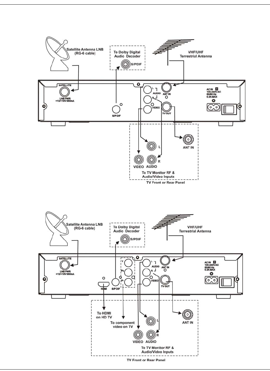
Rear Panels Connections
D9865B Satellite Receiver
D9865H Satellite Receiver
4035197 Rev C D9865 Satellite Receiver Installation and Operation Guide 1-5
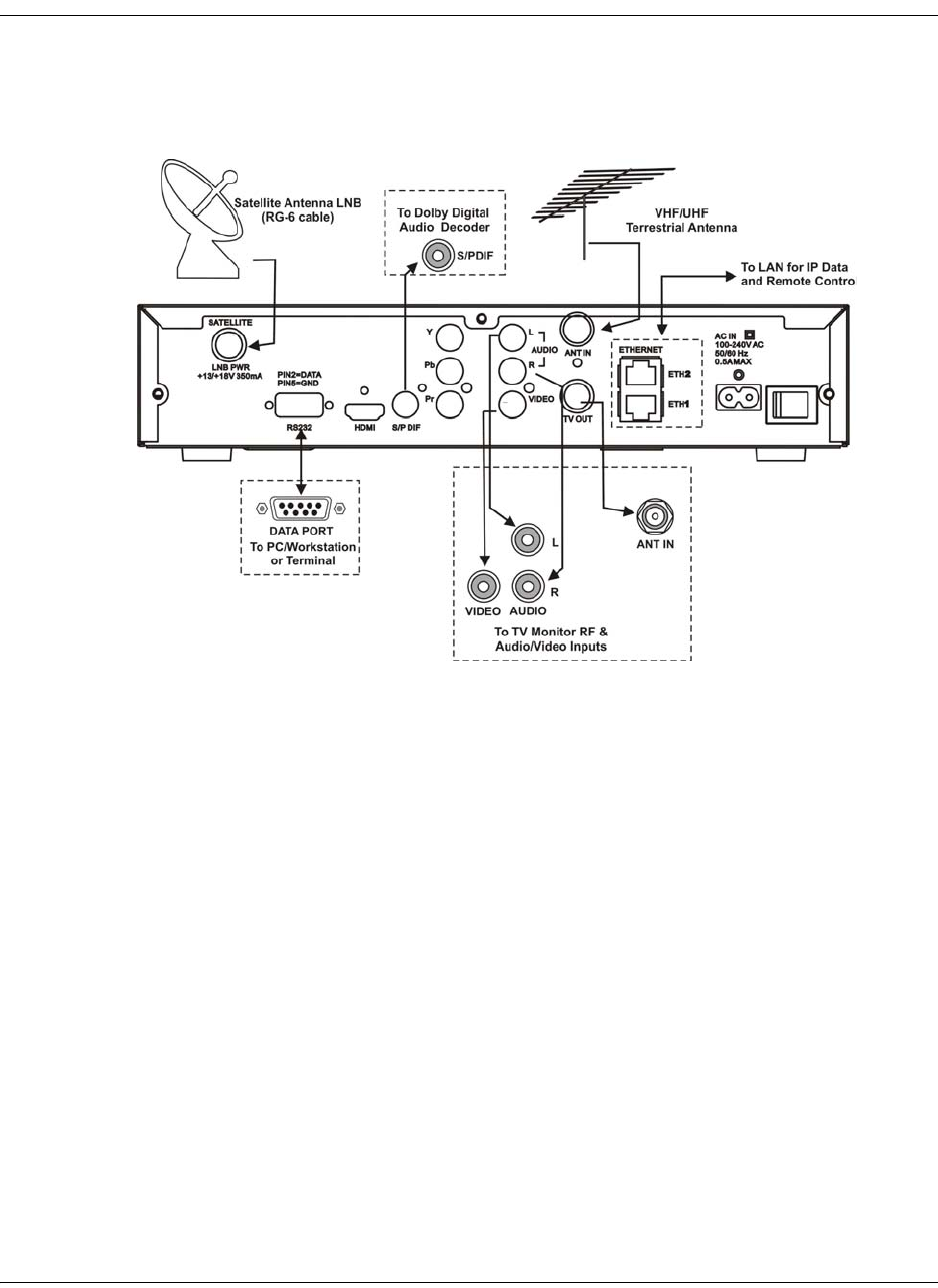
Rear Panels Connections, Continued
D9865D Satellite Receiver
Note: Only ETH1 Ethernet port is currently available.

1-6 D9865 Satellite Receiver Installation and Operation Guide 4035197 Rev C
4035197 Rev C D9865 Satellite Receiver Installation and Operation Guide 2-1
Chapter 2
Introduction
Overview
Introduction
This chapter is a general introduction to the Cisco® D9865 Satellite Receiver. It
describes the most common applications and interfaces of the receiver.
In This Chapter
This chapter contains the following topics.
Topic See Page
D9865 Satellite Receiver 2-2

2-2 D9865 Satellite Receiver Installation and Operation Guide 4035197 Rev C
D9865 Satellite Receiver
General Description
The Cisco D9865 Satellite Receiver is designed for satellite content distribution and
it targets the broadcast, business TV, private networks, and SMATV environment.
The receiver offers the ability to receive digitally encrypted video, audio, VBI, and
data. It provides a cost-effective, variable-rate solution to transition existing DVB-
S/MPEG-2 services to DVB-S2/MPEG-4. Additional features include IP data and
RS-232 utility data (D9865D only).
The unit is set up via the on-screen display menu, using a handheld infrared remote
control, or navigation keys on the front panel of the receiver. The unit can also be set
up and monitored using the embedded Web interface. User-editable presets are
provided for quick re-tuning to other broadcasts. The receiver also supports SNMP
control via the Ethernet port as an option.
Free-to-air Reception
This receiver is capable of receiving a DVB/MPEG compliant free-to-air broadcast.
Secured Broadcast Reception
Supporting the PowerVu conditional access with DES or DVB descrambling, or
with DVB Conditional Access Module (CAM) based DVB CA systems, this receiver
can be used to receive secured corporate communication of video, audio, and data
broadcast. It can also be used for secured delivery of TV programming to hotels,
MDUs, homes, and commercial establishments such as restaurants and stores.
Data Outputs (D9865D only)
Data outputs can be used for distribution of electronic documents, such as price lists
and video files. Utility data (RS-232) can be used for smaller file transfer at a slower
speed. DVB MPE IP data via an Ethernet interface allows for connection to a local
area network for larger file transfer or communication with multiple network
clients.
MIB Browser
A MIB Browser is a type of SNMP manager, which can be used to communicate
with SNMP agents. It is a tool for reading and writing to controls and status objects
defined by the MIB.
Note: A MIB file is included in the delivery from Cisco for the D9865 Satellite
Receiver to support 3rd party SNMP managers.

4035197 Rev C D9865 Satellite Receiver Installation and Operation Guide 2-3
D9865 Satellite Receiver, Continued
Key Features
The D9865 receiver provides the following key features:
• DVB-S QPSK, DVB-S2 QPSK/8PSK demodulation
• Variable QPSK symbol rates from 1 to 45 MS/s for DVB-S and 1 to 31 MS/s for
DVB-S2
•PowerVu
® conditional access with DES and DVB descrambling
• CAM interface hardware for DVB CAM-based descrambling
• 4:2:0 High Definition (HD) MPEG-2 and MPEG-4 AVC decoding
• 4:2:0 Standard Definition (SD) MPEG-2 and MPEG-4 AVC decoding
• 4:2:0 NTSC and PAL (B/G/I/D/M/N) video decoding
•MPEG, Dolby
® Digital Plus and HE-AAC audio decoding
• DVB Subtitling and DVB VBI (WST, WSS, VPS)
• One unbalanced stereo pair of audio outputs
• Line 21 closed caption and V-chip support
• Fingerprint trigger
• Service replacement
• Field upgradeable software and security
• Front panel 4-digit LED for channel display
• On-screen display menu for setup and status
• User-editable preset configurations
• Low Speed Data
• SNMP traps support for alarms and warnings
• MIB Browser support, used to manage SNMP requests
• Web browser interface for easy setup, control and monitoring
• Browse channels using the Electronic Program Guide (EPG)
Optional Features
The following features are available options:
• HDMI and component video outputs for HDTV (D9865H and D9865D only)
• Support HDCP on HDMI port (D9865H and D9865D only)
• Dual Ethernet 10/100BaseT for IP data and SNMP control (D9865D only)
• Multiprotocol Encapsulation (MPE) data support with static Unicast routes and
Multicast forwarding (D9865D only)

2-4 D9865 Satellite Receiver Installation and Operation Guide 4035197 Rev C
4035197 Rev C D9865 Satellite Receiver Installation and Operation Guide 3-1
Chapter 3
Front Panel Operation
Overview
Introduction
This chapter describes how to set up the D9865 Satellite Receiver using the front
panel keys and display. This information is primarily applicable for standalone
operation.
In This Chapter
This chapter contains the following topics.
Topic See Page
About the Front Panel 3-2
Common Interface Modules 3-5
Remote Control Functions 3-6
3-2 D9865 Satellite Receiver Installation and Operation Guide 4035197 Rev C
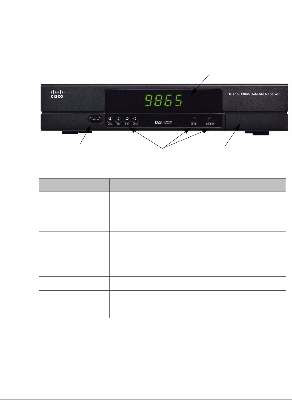
About the Front Panel
Introduction
The front panel of your satellite receiver provides controls for enabling the
receiver’s video output, and for interfacing with the remote control. MUTE,
SIGNAL and MENU LEDs are also provided. Some remote control buttons are
duplicated on the front panel for activating and navigating menus.
CI Slot
Navigation Selection
Display Button
LCD Panel
Button Function
DISPLAY • Enables the video display output.
• When the video display is enabled, the channel
number is displayed on the front panel. When switched
off, a “.” flashes.
MENU • Enters Menu mode or returns to video.
• Returns to previous menu.
SELECT • Selects menus.
• Enters or exits edit mode.
• In Menu mode, used to navigate menus.
• In Video mode, used for volume up/down.
• In Video mode, used for channel up/down.

4035197 Rev C D9865 Satellite Receiver Installation and Operation Guide 3-3
About the Front Panel, Continued
To change a setting on a menu using the front panel:
1. Use the buttons to move to the setting you want to change. Press the
Select button to select the setting.
2. For numeric options, you can:
•use the buttons to change the value one digit at a time, or
• navigate to Keyboard using the buttons to use an on-screen
keyboard.
3. To access the menus at the bottom of the screen (for example, Save), navigate to
the appropriate selection using the buttons and press Select. A help
message is displayed at the bottom of the screen.
4. Press Menu to move to the previous menu.
Front Panel LEDs
The functions of the LEDs are described in the table below.
CI Slot
The CI Slot allows the use of CAM (Conditional Access Module) Smart Card to
decrypt purchased programming. For setup information, see Viewing DVB-CI
Information, on page 4-77 and Configuring the Common Interface (CI)
Information, on page 5-28. For a list of supported CAMs, refer to Common
Interface Modules, on page 3-5.
LED Function
MUTE • On when sound is muted.
SIGNAL • On when receiver is synchronized with the incoming
digital signal and authorized for the current channel.
• Flashing when a signal has been found, but receiver is
not authorized for the current channel.
• Off when no signal has been found. For more
information about troubleshooting your satellite
receiver, see Troubleshooting, on page 7-19.
MENU • On when on-screen menus are displayed.

3-4 D9865 Satellite Receiver Installation and Operation Guide 4035197 Rev C
About the Front Panel, Continued
Keyboard Display
Press the MENU and SELECT buttons simultaneously on the Front Panel to display
a keyboard on the TV monitor. The keyboard allows alphabetical and numerical
character entry in menu fields using the front panel. Alternatively, press the red
button on the remote control.
Note: You must have a menu field selected (i.e., must be in edit mode) to display
the keyboard.
1. Use the arrow buttons to move along the keyboard.
2. Press OK to select a number or letter for each entry.
Setting the TV Video Format
The video format is set to the standard format for your country. Check with your
satellite or local service provider before changing this setting to ensure it is set
correctly. If you are instructed to change this setting for your TV set:
1. Press the SELECT and buttons on the receiver front panel at the same time.
2. Press SELECT and again. The video format is displayed on the receiver front
panel (e.g., NTSC, PAL, etc).
3. Press until you display your video format. Each change is viewable on-
screen.
4. Press SELECT to save the setting and re-display the selected channel.
Note: You must be in video mode (i.e., on-screen menus not displayed) to
perform this function on the receiver front panel.
Note: This function is not available through the remote control.
4035197 Rev C D9865 Satellite Receiver Installation and Operation Guide 3-5
Common Interface Modules
Only CAMs purchased from Cisco are currently supported. The following lists the
supported CAMs:
Common Interface Modules Part Number
Aston Professional CAM, for descrambling CONAX 4016669
Aston Consumer CAM for descrambling CONAX 4016670
CAM for descrambling CryptoWorks V9523361
Aston Professional CAM for descrambling Irdeto 4016671
Aston Consumer CAM for descrambling Irdeto 4016672
Aston Professional CAM for descrambling MediaGuard V9528197
Aston Consumer CAM for descrambling MediaGuard V9528198
Aston Professional CAM for descrambling Viaccess V9528199
Aston Consumer CAM for descrambling Viaccess V9528240
3-6 D9865 Satellite Receiver Installation and Operation Guide 4035197 Rev C
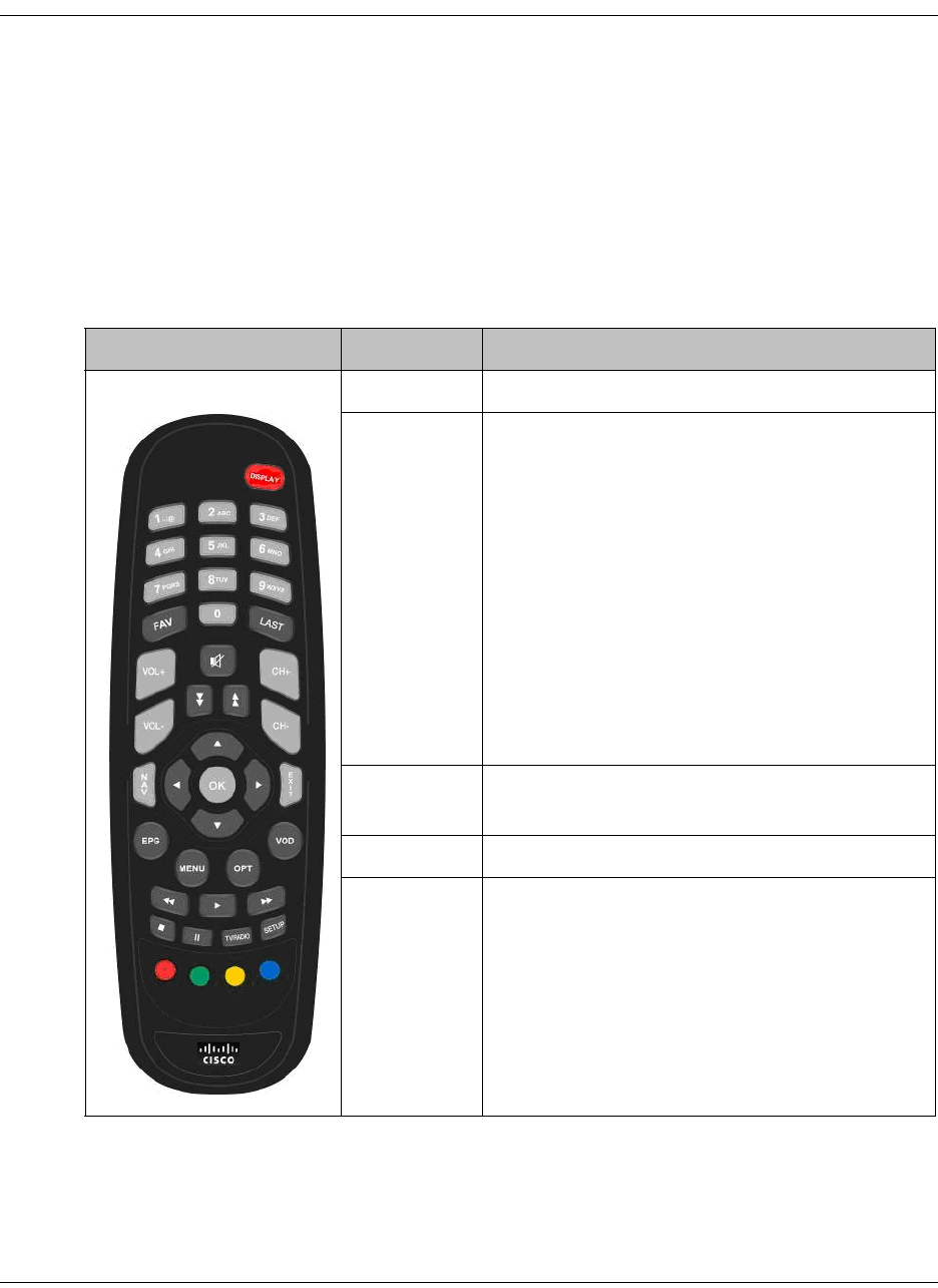
Remote Control Functions
The remote control is provided as a standard feature with the D9865 Satellite
Receiver. After unpacking your satellite receiver, check that you have the following
accessories (if ordered):
• One IR (Infra-Red) Remote Control transmitter (RCU)
• Two AAA size batteries for Remote control (not included for Argentina)
The Remote Control is used to control receiver functions. You can switch the video/
audio outputs on and off plus activate and navigate the on-screen menus. Some
remote control functions are duplicated on the front panel (see Front Panel LEDs,
on page 3-3).
Remote Control Button Function
DISPLAY • Enables the video/audio outputs.
0 to 9 • Enters channel numbers or information on
on-screen menus.
•Alphanumeric character entry for “Name”
field on the on-screen menus (similar to keys
on telephone keypad). If an entered value is
out of range or conflicts with another setting,
a pop-up message displays information
about the error.
00 (pressing 0 twice) – deletes a character at
the cursor location.
11 (pressing 1 twice) – adds a space at the
cursor location.
FAV • Displays Favorite screen where you can
view and set favorite channels.
LAST • Displays last channel.
MENU • Displays Main Menu.
• Exits edit mode in menus.
• Returns to video in video mode.
• Returns to previous menu.
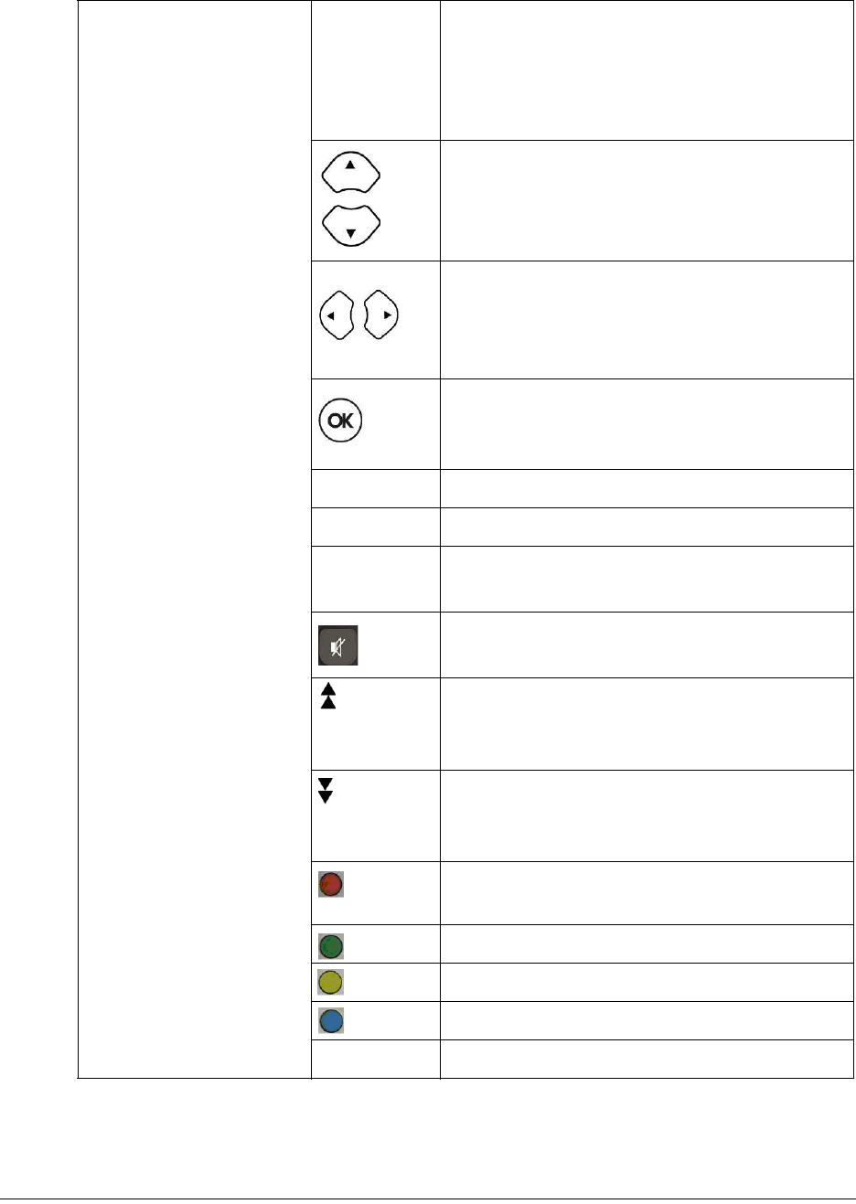
4035197 Rev C D9865 Satellite Receiver Installation and Operation Guide 3-7
EPG • If the receiver is enabled to receive EPG
(Electronic Program Guide) data, an
interactive EPG guide will be displayed
when pressed. If not, a channel list menu and
video will be displayed.
• In Video mode, used to select channels.
• In Menu mode, used to move through on-
screen menus.
• In Video mode, increases or decreases
volume.
• In Menu mode, used to move through on-
screen menus.
• Selects menus (functions same as SELECT
button on front panel).
• Enters or exits edit mode.
CH+, CH- • Channel up/down.
VOL+, VOL- • Volume up/down.
EXIT •Exits from edit mode.
• Exits menus (returns to video).
• Mutes sound.
• Changes to uppercase letter mode.
• Page up when scrolling the on-screen
menus.
• Changes to lowercase letter mode.
• Page down when scrolling the on-screen
menus.
• Red – different on each menu. Aso
displays the soft keyboard.
• Green – different on each menu
• Yellow – different on each menu
• Blue – different on each menu
Setup • Displays the Setup Menu.

3-8 D9865 Satellite Receiver Installation and Operation Guide 4035197 Rev C

4035197 Rev C D9865 Satellite Receiver Installation and Operation Guide 4-1
Chapter 4
Setup and Monitoring via On-Screen Display
Overview
In This Chapter
This chapter contains the following topics.
Topic See Page
Main Menu 4-3
Channel List without EPG 4-6
Introduction to the EPG 4-7
Setting Timers 4-10
Setting Up Your Favorite Channels 4-13
Setting Up One Button Channel Change 4-16
Setup Menu 4-17
Setting up Tuning / Preset 4-18
Setting up the Preset / LNB 4-21
Setting up LNB 4-23
Setting Up the Satellite Dish 4-26
Setting up the Video 4-33
Setting up Subtitles 4-40
Setting up Audio 4-42
Advanced Setup 4-44
Setting up Advanced User Settings 4-45
Changing the Lock Level Password 4-48
Setting up POV Mode 4-50
Network Setup 4-52
Configuring Noise Cutoffs 4-63
Setting up Alarms and Warnings 4-67
Viewing Downloads 4-69
Setting Bootable Application Selection 4-70
4-2 D9865 Satellite Receiver Installation and Operation Guide 4035197 Rev C
System Information 4-71
Viewing the Version Information 4-72
Viewing Hardware Information 4-73
Viewing Installed Options 4-74
Viewing Service Information 4-75
Viewing Channel Information 4-76
Viewing DVB-CI Information 4-77
Viewing Device Status Information 4-79
Viewing the RF Status 4-82
Viewing Advanced RF Diagnostics 4-84
Viewing ADP Status 4-85
Topic See Page
4035197 Rev C D9865 Satellite Receiver Installation and Operation Guide 4-3
Main Menu
This section contains the information you need to set up your Satellite Receiver
using the on-screen display menus. Before you begin using the receiver, you may
need to change the current settings to suit your operating requirements.
To display the Main Menu, press the MENU button on the remote control or
receiver front panel.
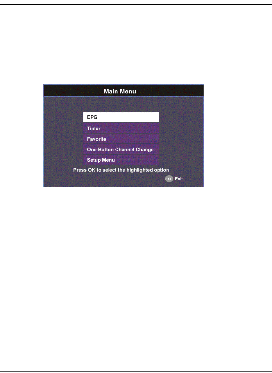
If the D9865 Satellite Receiver is enabled to receive Electronic Program Guide (EPG)
data, the following Main Menu screen appears.
As shown above, you can select the EPG, Timer, Favorite, One Button Channel
Change, or the Setup Menu.
• EPG - displays an interactive EPG guide with all the available subscriber
channels.
• Timer - Displays reminder timers set for upcoming programs.
• Favorite - Displays a list of favorite channels set by the user.
• One Button Channel Change - Ability to assign a channel to each of the colored
buttons at the bottom of the remote control.
• Setup Menu - provides access to menus to set up tuning, select and set up presets,
set up video, audio, and other advanced parameters, in addition to viewing the
receiver operating status.
4-4 D9865 Satellite Receiver Installation and Operation Guide 4035197 Rev C
Main Menu, Continued
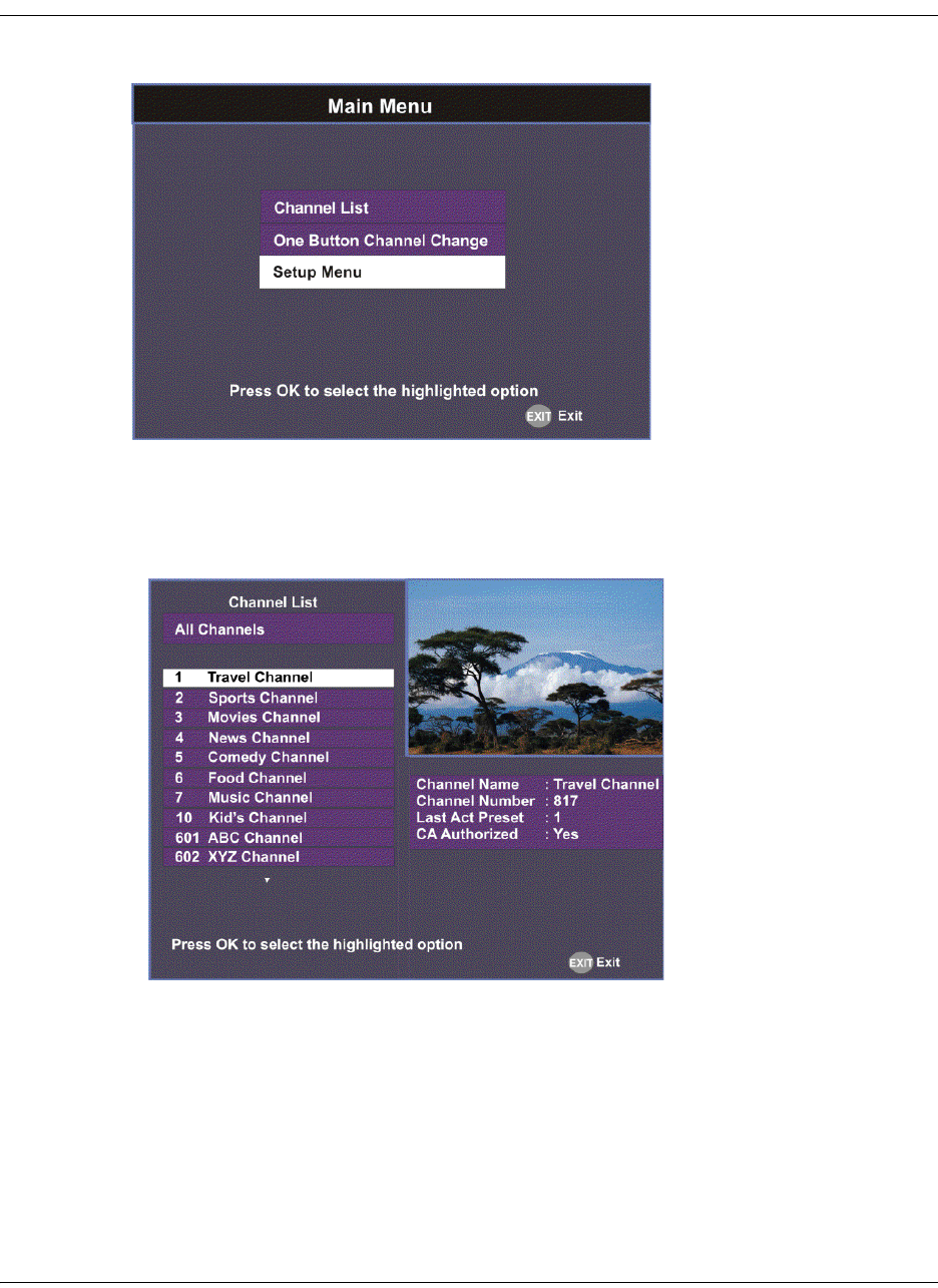
If the receiver does not support EPG, the following Main Menu screen appears:
As shown above, you can select the Channel List, One Button Channel Change, or
the Setup Menu.
• Channel List – displays all the available subscriber channels. See an example of a
Channel List below.
• One Button Channel Change - provides ability to assign a channel to each of the
colored buttons at the bottom of the remote control.
• Setup Menu - provides access to menus to set up tuning, select and set up presets,
set up video, audio, and other advanced parameters, in addition to viewing the
receiver operating status.
4035197 Rev C D9865 Satellite Receiver Installation and Operation Guide 4-5
Main Menu, Continued
About using the on-screen menus
All screens or menus are accessed from the Main Menu. While viewing any
channel, you can display on-screen menus for viewing or changing the current
receiver setup. While in menus, you can change the current receiver settings, and/
or display other menus. Some menus contain status information, which is available
for viewing only and cannot be changed.
To change a setting on a menu using the remote control:
1. Use the buttons to move to the setting you want to change.
2. Press the OK button to select the setting.
3. For numeric options, you can use one of the following methods:
• enter the number directly using the numeric keypad on the remote control,
•use the buttons to change the value one digit at a time, or
• press the red button (keyboard) to use an on-screen keyboard.
4. Press OK to save the setting and exit the menu. A help message is displayed at
the bottom of the screen.
5. Press MENU to move to the previous menu.
Note: The steps in this chapter are based on using the remote control. For more
information on changing a setting on a menu using the front panel controls, see
About the Front Panel, on page 3-2.
The On-Screen Buttons
The on-screen menus have the following common buttons:
About the Current Channel
When you navigate to menus from a video channel, the information displayed is
associated with the current (video) channel. If no changes have been made to the
current setup, you are automatically returned to the same video channel when you
exit to video.
Button Description
Save Saves and applies the settings to the
receiver.
Exit Exits edit mode and menu. A message
prompts you to save or discard changes
before you exit the menu.

4-6 D9865 Satellite Receiver Installation and Operation Guide 4035197 Rev C
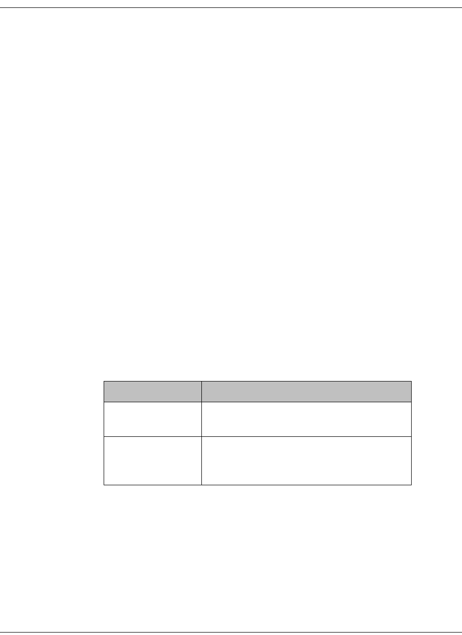
Channel List without EPG
If the receiver does not support EPG, you can access the Channel List from the Main
Menu.
To select a channel from the channel list:
1. From the Main Menu screen, select Channel List and press OK. The Channel
List displays all the available subscriber channels.
2. Select a channel from the channel list and press OK. This will tune to the
selected channel (top right) and the channel information is displayed in the
bottom right of the channel list:
The channel lost screen will close when pressing OK.
Options Description
Channel Name Name of the current channel.
Channel Number Current channel number.
Last Act Preset Indicates the number of the last activated
preset.
CA Authorized Indicates whether the receiver is
authorized to receive the signal.

4035197 Rev C D9865 Satellite Receiver Installation and Operation Guide 4-7
Introduction to the EPG
What is EPG?
The Electronic Program Guide (EPG) is a convenient way to find out what is on
your TV and to view a list of upcoming programs. Lists of programs are available
for any date in the next 7 days depending on the network provider.
Features of the EPG
The following list provides an overview of the features of an EPG:
• With the browsing features, you can see what is on TV for a particular channel,
program channel, or program title.
• Instant program descriptions appear while using the browsing feature to view
detailed channel information.
• Timers help you keep track of upcoming programs by providing reminders on
the screen before the program starts.
• You can set up Favorite profiles for a quick browse of your favorite channels.
Browsing By Channel
From the Main Menu, select EPG and press OK. The EPG main screen is shown
below. The EPG screen enables you to browse by channel, which lists all the
available programs in order by time of day and date.
Channels
Program you are
watching is reduced
to fit in this area
Main Program
listing
Channel Banner
describes high-
lighted program
Current Favorite
profile
Date and Time of
the program
Current Date and Time
Program extends
Time beyond the grid
end time
4-8 D9865 Satellite Receiver Installation and Operation Guide 4035197 Rev C
Introduction to the EPG, Continued
Parts of the Guide
The following list describes the parts of the guide.
• The program you are watching is reduced to fit in the upper right are of your
screen. The program remains there while you are using the main functions of the
guide.
• The current Information banner under the picture provides the current date, time
and channel.
• The Channel Banner provides a description for each program you highlight in the
main program list.
• The Main Program listing displays the programs that will be broadcast.
• Press the blue button (Timers) to view the list of timers set for upcoming
programs.
• Press the red button (Favorite) to view the list of Favorite profiles.
Browsing by a Different Date
You can view upcoming program information for up to 7 days in advance by
changing the day of the week you are browsing.
Press the yellow button (Next Day) or the green button (Prev Day) to change the
day of the week to view upcoming program information on the following day.
Press the green button (Prev Day) to view the program information.
Viewing Favorites
Press the red button (Favorite) to view a list of all the configured Favorite profiles.
For more information on setting up the favorite profiles, see Setting Up Your
Favorite Channels, on page 4-13.
4035197 Rev C D9865 Satellite Receiver Installation and Operation Guide 4-9
Introduction to the EPG, Continued
Viewing Timers
Press the blue button (Timers) to view all the configured timer profiles.
For more information on setting up and maintaining timer profiles, see Setting
Timers, on page 4-10.
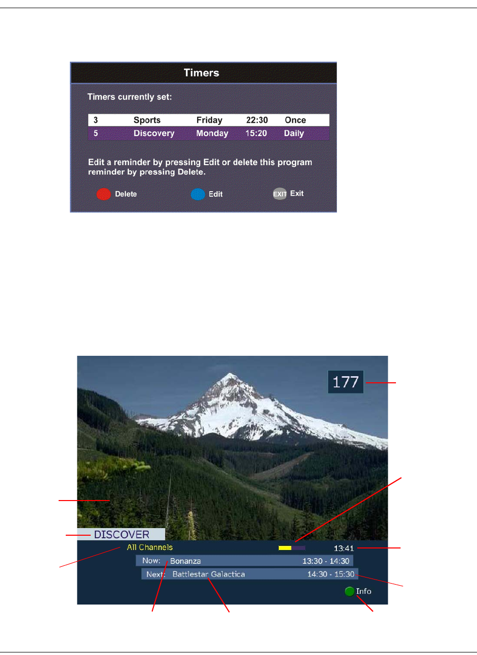
Changing Channels
As you change the channel while watching TV, a brief channel banner appears
along the bottom of the TV screen with the current time and channel information.
For program details, press the green button (Info). The Extended Info screen is
displayed, with additional program information. The following displays an
example of a channel banner:
Program being
watched
Current program
name
Upcoming program
name
Press for more information on
the current program
Current
Channel
Number
Current time
Current Channel
Name
Time progress for
the current
program
Current Favorite
Profile Start/End time
of program
4-10 D9865 Satellite Receiver Installation and Operation Guide 4035197 Rev C
Setting Timers
Setting a Reminder Timer From EPG
You can set up timers that will display a reminder on-screen when the configured
program is on.
Note: You cannot set a timer for a program that has already started.
Proceed as follows to set a reminder timer from EPG:
1. From the Main Menu screen, select EPG and press OK.
2. Select an upcoming program you want to set a reminder by scrolling through
the guide using the buttons and then press OK. The Extended Info
screen is displayed with the channel name, information and program time.
3. If the program selected has already started, press Next to set a timer for the
next time slot.
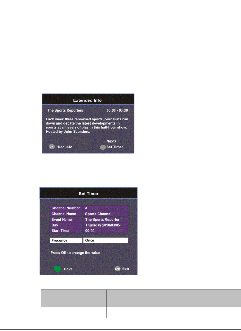
4. Press the green button (Set Timer). The Set Timer screen is displayed.
5. The following table describes the channel information and the timer options:
Channel/Timer
Information
Description
Channel Number Number of the selected channel.
4035197 Rev C D9865 Satellite Receiver Installation and Operation Guide 4-11
6. Click the green button (Save) to save your timer settings.
Note: You can set a maximum of 50 timer profiles.
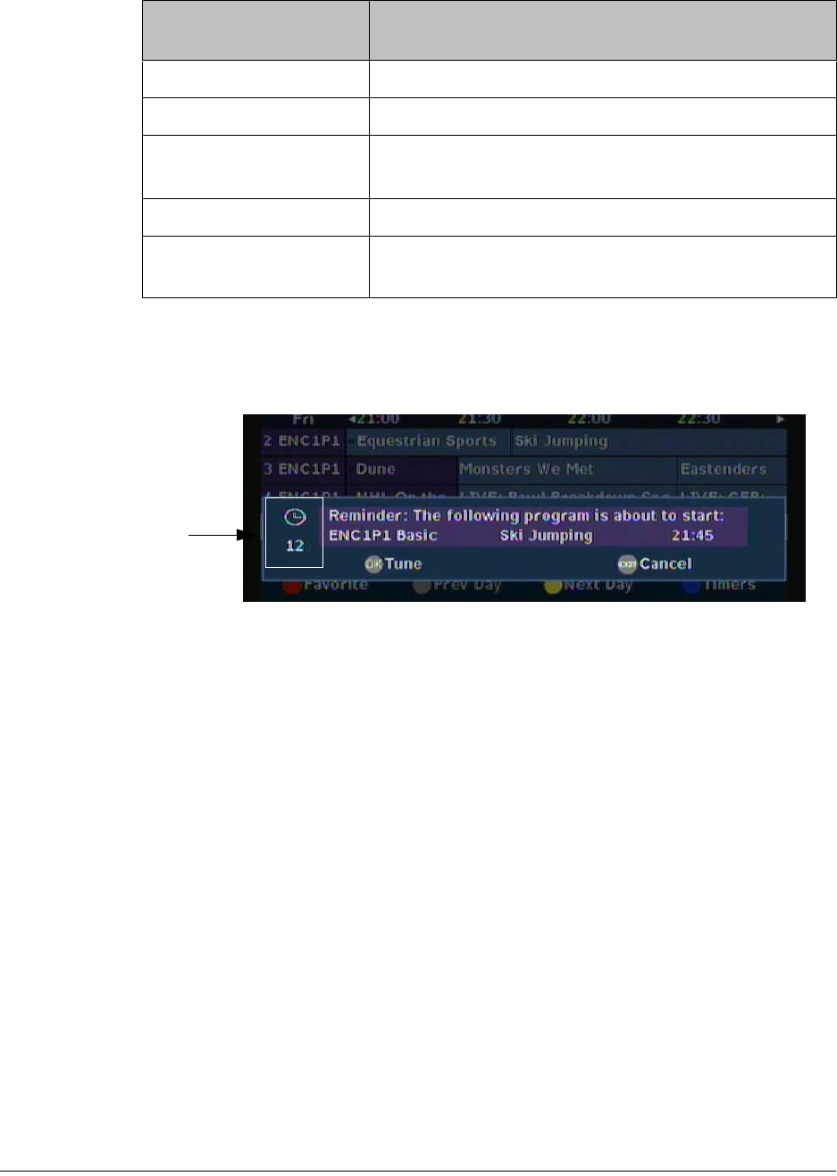
The following is an example of a reminder that appears on-screen:
Press OK to close the reminder window and tune to the specified channel.
Otherwise, press Exit to close the reminder window.
The clock symbol on the left hand side displays a countdown of seconds left
before the program starts and the reminder window closes.
Channel Name Name of the selected channel.
Event Name Name of the selected program.
Day Day of the week the program will be on the selected
channel.
Start Time Start time of the selected program.
Frequency Set the frequency of the reminder: Once, Daily,
Weekly, or Weekdays.
Channel/Timer
Information
Description
Seconds left
before the
program
starts
4-12 D9865 Satellite Receiver Installation and Operation Guide 4035197 Rev C
Setting Timers, Continued
Editing a Timer Profile
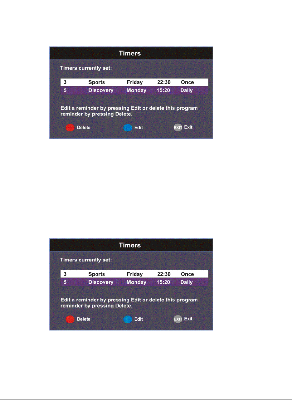
1. From the Main Menu, select Timers and press OK. The Timers screen is
displayed.
2. From the Timers screen, scroll to the Timer profile you want to edit using the
buttons.
3. Select Edit or press the blue button (Edit). The Set Timer screen is displayed.
4. Make the necessary changes.
5. Press the green button (Save) to save the Timers list.
Deleting a Timer Profile
1. From the Main Menu, select Timers and press OK. The Timers screen is
displayed.
2. From the Timers screen, scroll to the Timer profile you want to delete using the
buttons.
3. Select Delete or press the red button (Delete). A warning message appears
confirming your deletion.
4. Press OK to confirm.
4035197 Rev C D9865 Satellite Receiver Installation and Operation Guide 4-13
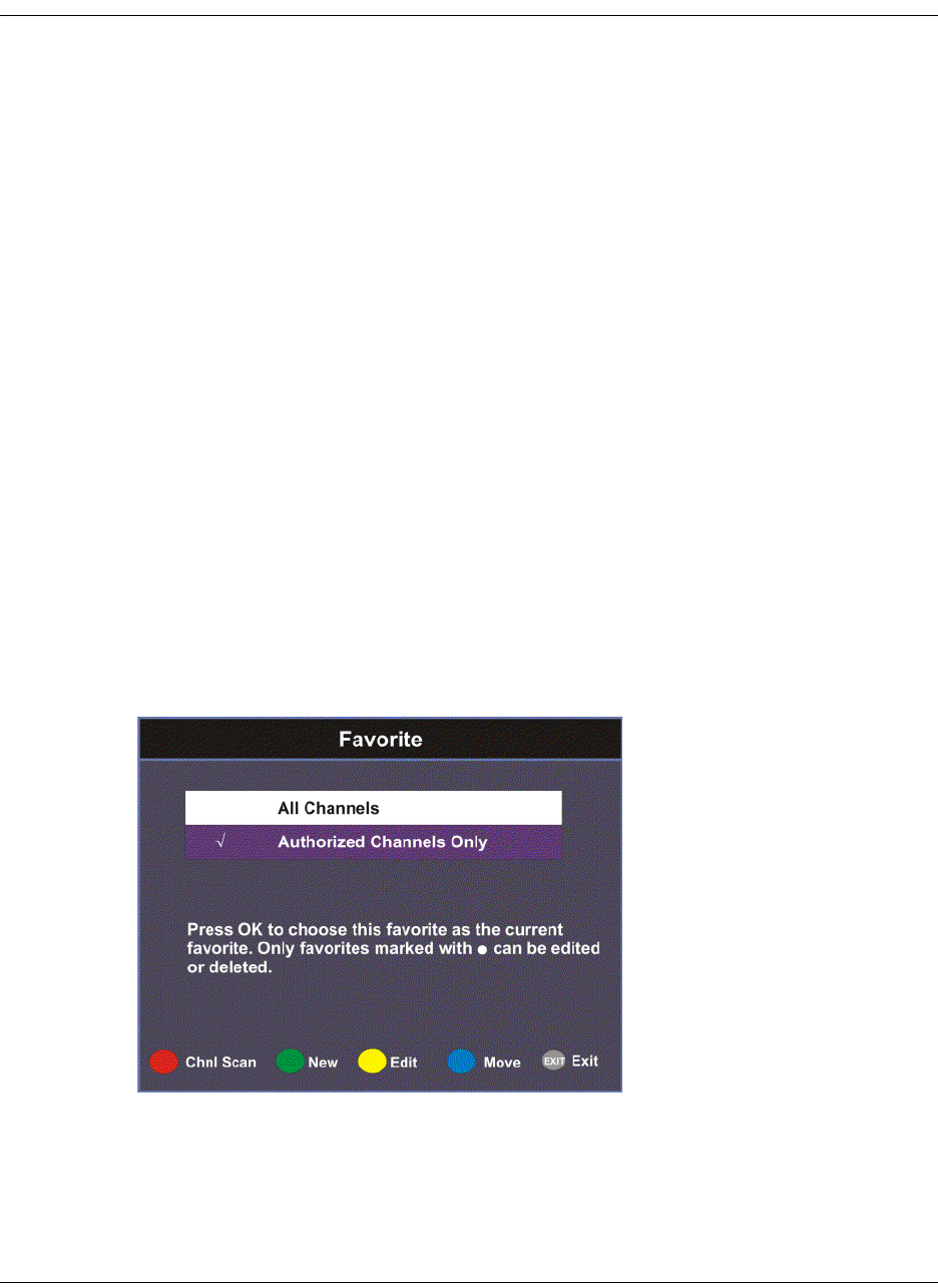
Setting Up Your Favorite Channels
The Favorite screen displays a list of all the favorites configured in the D9865.
Favorites allow you to surf through the channels you have set up as your favorite
channels, skipping over other channels.
By default, All Channels (authorized and unauthorized channels) are displayed.
The Authorized Channels Only lists channels that are authorized by your uplink
provider. Setup is authorized only by doing a channel scan.
Adding a Favorite Profile
Proceed as follows to configure your favorites list:
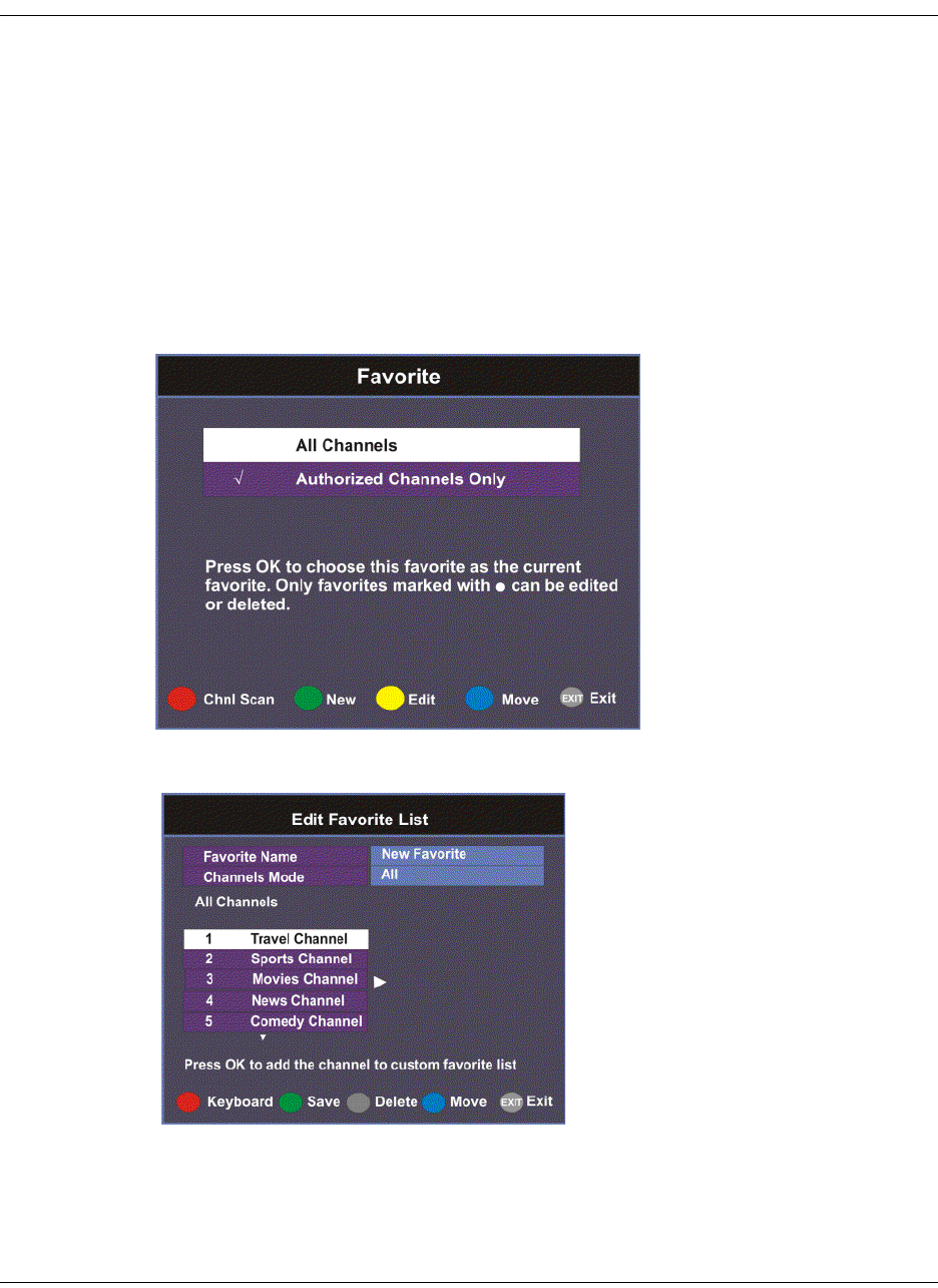
1. From the Main Menu screen, select Favorite and press OK, or press FAV.
2. Press the green button (New) to create a new Favorites list.

4-14 D9865 Satellite Receiver Installation and Operation Guide 4035197 Rev C
Setting Up Your Favorite Channels, Continued
3. Select Favorite Name and press OK to edit the new favorite name. Enter the
name directly using the numeric keypad on the remote control or use the
buttons to change the letters/numbers one alphabet/digit at a time.
Alternatively, press the red button (Keyboard) to enter the name using an on-
screen keyboard.
4. Select the Channel Mode and press OK to select the type of channels listed
below. Select All to list all the channels in the network. Select Authorized Only
to list all the channels that are authorized by your uplink provider only.
5. Scroll through the channel list using the buttons and press OK to add the
channels you want to your new favorites list on the right. A checkmark appears
to the left of the channel, indicating that the channel is in the favorites list.
6. Press the button to edit the selected channels on the right. Press the blue
button (Move) to move the selected channel up/down the list using
buttons. When you are done moving the channel, press the blue button (End
Move).
7. Press the green button (Save) to create and save the new Favorites list.
Editing a Favorite Profile
Note: You cannot edit All Channels or the authorized channels only.
1. From the Favorite screen, scroll to the Favorite profile you want to edit using the
buttons.
2. Press the yellow button (Edit). The Edit/Delete Custom Favorite screen is
displayed.
3. Select Edit or press the blue button (Edit). The Edit Favorite List screen is
displayed.
4. Make the necessary changes.
5. Press the green button (Save) to save the Favorites list.
Deleting a Favorite Profile
Note: Only Favorites that are marked with a circle can be deleted.
1. From the Favorite screen, scroll to the Favorite profile you want to delete using
the buttons.
2. Press the yellow button (Edit). The Edit/Delete Custom Favorite screen is
displayed.
3. Select Delete or press the red button (Delete). A warning message appears
confirming your deletion.

4035197 Rev C D9865 Satellite Receiver Installation and Operation Guide 4-15
Setting Up Your Favorite Channels, Continued
4. Press OK to confirm.
Performing a Channel Scan
The Channel Scan function scans through all the available channels and updates the
Authorized Channels Only list. For more information on your authorized channels,
contact your uplink service provider.
Proceed as follows to perform a channel scan:
1. From the Favorite screen, press the red button (Chnl Scan). A warning message
appears confirming the channel scan. It can take several minutes, depending on
the size of the network.
2. Press OK. The Authorized Channels Only list is updated.

4-16 D9865 Satellite Receiver Installation and Operation Guide 4035197 Rev C
Setting Up One Button Channel Change
To Set Up One Button Channel Change
Proceed as follows to set up one button channel change:
From the Main Menu, select One Button Channel Change and press OK.
The Button colors (Red, Green, Yellow, and Blue) corresponds to the colored
buttons at the bottom of the remote control (see below).
Each color can be assigned to a channel as a shortcut for a quick channel change. For
example, if you assign the red button to channel 1, pressing the red button while
watching a different channel at anytime will automatically tune the TV channel to 1.
Note: You can only use the one button channel change if the screen is displaying
video only. The one button channel change does not work if EPG, Channel Banner
or on-screen menus are displayed.
4035197 Rev C D9865 Satellite Receiver Installation and Operation Guide 4-17
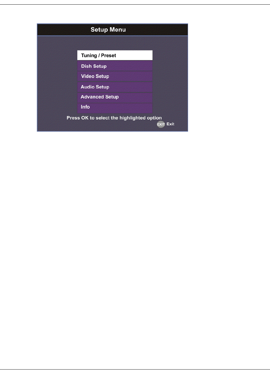
Setup Menu
The Setup Menu is used to set up the receiver.
The available sub-menus are as follows:
• Tuning / Preset
From this menu, you can display and change Presets, and set up the LNB.
•Dish Setup
This menu provides a graphical aid for dish pointing/alignment.
•Video Setup
From this menu, you can set the TV channel to display video on your TV, the
video format (e.g., NTSC or PAL), TV aspect ratio, and subtitling control.
• Audio Setup
From this menu, you can set the Stereo/Mono selection and select digital audio
preferences.
• Advanced
From this menu, you can access other sub-menus for control and display of
features such as Lock Level, Conditional Access, the Ethernet port and
Diagnostics, and available services to control code downloads.
•Info
From this menu, you can access other sub-menus to display information about
the receiver software, and hardware versions, view device status and other
signal-related parameters.

4-18 D9865 Satellite Receiver Installation and Operation Guide 4035197 Rev C
Setting up Tuning / Preset
To Set Up Tuning/Preset Parameters
The Tuning/Preset menu is used to display and configure the current settings.
Proceed as follows to set up the tuning/preset:
1. From the Setup Menu screen, select Tuning / Preset and press OK.
2. The following table describes each of the available options:
Selection Options Description Default
Modulation Type DVB-S Enter the modulation scheme. DVB-S2
DVB-S2
Downlink (Freq) Enter
number
For C-Band:
Downlink Freq = LO Freq - L-Band Freq.
For Ku-Band:
Downlink Freq = LO Freq + L-Band Freq.
12.3
Symbol Rate 1.0 to 45.0
1.0 to 31.0
Range for DVB-S in MS/s.
Range for DVB-S2 in MS/s.
30.0
NetId Enter
number
Obtain the number from your service
provider.
1

4035197 Rev C D9865 Satellite Receiver Installation and Operation Guide 4-19
LO Select
(Sets a 22 kHz tone
for Ku-band dual
LNB)
On Switches 22 kHz tone on. Off
Off Switches 22 kHz tone off.
Auto Sets 22 kHz tone to automatic.
If Downlink Freq < Crossover, use LO
Freq 1. The 22 kHz tone is Off.
If Downlink Freq > Crossover, use LO
Freq 2. The 22 kHz tone is On.
LO Freq 1 Enter
number
If C-band application, set to 5.15 GHz
(default).
If Ku-band single LNB, enter LO Freq. and
set LO Freq 2 and Crossover to 0.0.
If Ku-band dual LNB, enter LO Freq 1, LO
Freq 2 and Crossover.
10.75 GHz
LO Freq 2 Enter
number
Enter if Ku-band dual LNB application.
LO Freq 2 > LO Freq 1.
0.0
Crossover Enter
number
Enter if Ku-Band dual LNB application.
Determines if LO Freq 1 or LO Freq 2 is
used for tuning.
0.0
LNB Power
(For more
information, see
LNB Power
Settings, on
page 4-25.)
18-H For H polarization (18V). 18-H
13-V For V polarization (13V).
Off Use for external LNB power.
Note: LNB power must be on if DiSEqC is
required.
H-NIT Initially applies the horizontal
polarization voltage, and then follows the
polarization based on the NIT.
V-NIT Initially applies the vertical polarization
voltage, and then follows the polarization
based on the NIT.
DiSEqC Enable Enables or disables Digital Satellite
Equipment Control. This must be enabled
to control the DiSEqC switch. LNB Power
must be on to use this setting. Refer to
http://www.eutelsat.com/satellites/
4_5_5.html for more information.
Disable
Disable
DiSEqC Switch Off Selects a port on the LNB switch (if used). Off
A to P
Selection Options Description Default

4-20 D9865 Satellite Receiver Installation and Operation Guide 4035197 Rev C
Note: If you enter an invalid frequency setting or a setting that does not correspond
to the selection, a pop-up message such as “Input value out of range" is displayed.
3. Press the green button (Save) to save and apply the settings to the receiver.
Signal Lock Indicates signal synchronization status.
Signal Quality Indicates the quality of the received signal,
associated with the Bit Error Rate, in the
range from 0 to 100.
Signal Level Indicates the strength of the received
signal in the range from 0 to 100.
Selection Options Description Default
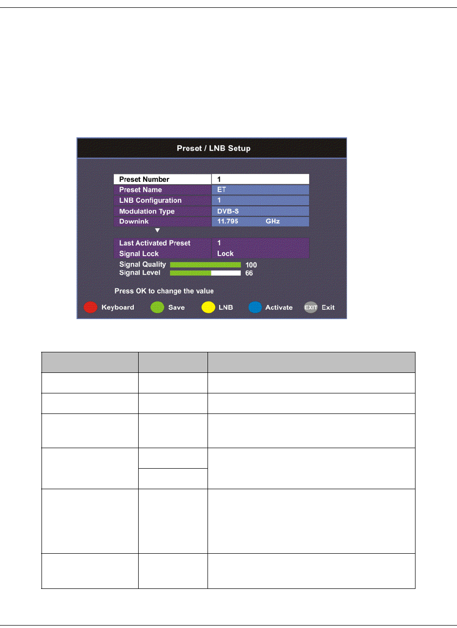
4035197 Rev C D9865 Satellite Receiver Installation and Operation Guide 4-21
Setting up the Preset / LNB
To Set Up Preset/LNB Parameters
The Preset/LNB Setup sub-menu allows you to select or configure up to 64 network
presets. Your receiver may be shipped pre-configured with a number of network
presets. You can configure the network preset to use one of 10 LNB configurations.
Proceed as follows to set up the preset/LNB settings:
1. From the Tuning / Preset screen, press the yellow button (Preset) to set up the
Preset/LNB.
2. The following table describes each of the available options:
Selection Options Description
Preset Number 1 to 64 Enter or select the preset number.
Preset Name Enter name Set the preset network name.
LNB
Configuration
1 to 10 Enter or select the LNB configuration.
Modulation Type DVB-S Select the modulation scheme.
DVB-S2
Downlink (Freq) Enter
number
For C-Band,
Downlink Freq = LO Freq - L-band Freq.
For Ku-Band,
Downlink Freq = LO Freq + L-band Freq.
Symbol Rate 1.0 to 45.0
1.0 to 31.0
Range for DVB-S in MS/s.
Range for DVB-S2 in MS/s.

4-22 D9865 Satellite Receiver Installation and Operation Guide 4035197 Rev C
3. Press the green button (Save) to save and apply the settings to the receiver.
Selecting the Active Preset
To change the displayed preset to the Active preset or to select a different preset as
the active preset:
1. From the Tuning/Preset screen, press the yellow button (Preset).
2. Enter the preset in the Preset field that you want to activate. Enter the number
directly using the numeric keypad on the remote control or use the
buttons to change the number one digit at a time. Alternatively, press the red
button (keyboard) to enter the preset using an on-screen keyboard.
3. Select Activate (blue button) to choose the preset. This will activate the currently
displayed preset as the active preset.
You will be prompted to accept the new preset and warned that service
interruption will occur.
4. Select OK to proceed or EXIT to cancel the operation.
5. Press MENU to go to the previous menu.
Note: It will take up to 30 seconds for signal acquisition to occur. It can take longer
if the symbol rates are low.
Editing Network Presets
You can edit or pre-configure any one of 64 presets without affecting the operation
of the receiver.
To save or change a network preset:
1. Enter a Preset Number and a name directly to below the Preset Number. Follow
the editing rules for the keys when entering characters in the Name field.
2. Enter the appropriate settings as described in the preceding table. Ensure that
the LNB selection corresponds to the correct downlink frequency.
3. Press OK to save the preset.
NetId Enter
number
Obtain the number from your service
provider.
Last Activated
Preset
Indicates the number of the last activated
preset.
Signal Lock Indicates signal synchronization status.
Signal Level Indicates the relative strength of the
received signal, in the range from 0 to 100.
Selection Options Description
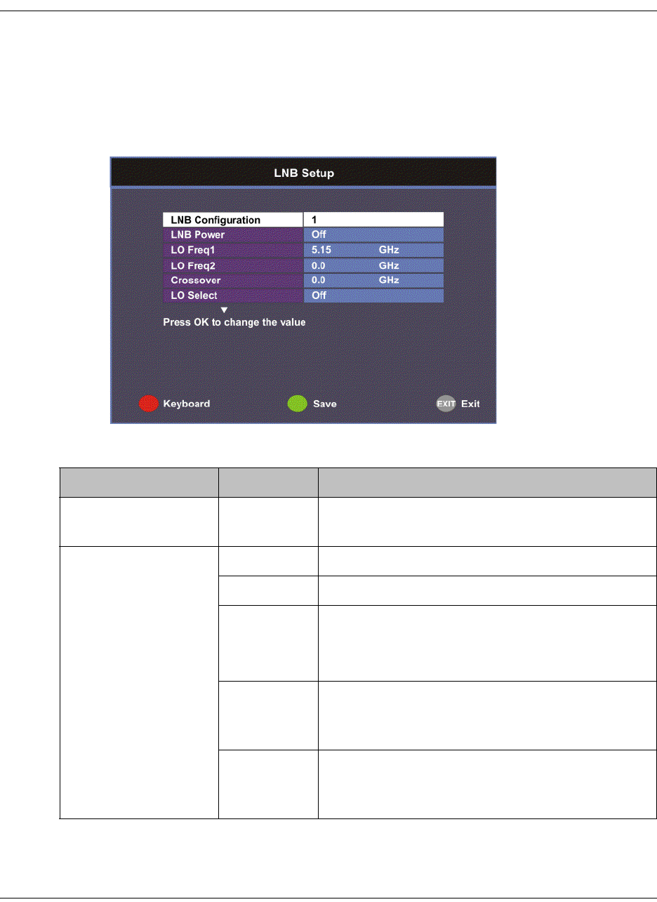
4035197 Rev C D9865 Satellite Receiver Installation and Operation Guide 4-23
Setting up LNB
To Set Up LNB Parameters
Proceed as follows to set up the LNB:
1. From the Preset/LNB Setup menu, press the yellow button (LNB) to set up the
LNB.
Note: You can configure up to 10 LNB presets.
2. The following table describes each of the options:
Selection Options Description
LNB Configuration 1 to 10 Number identifying the current preset LNB
configuration.
LNB Power
(For more
information, see LNB
Power Settings, on
page 4-25.)
18-H For H polarization.
13-V For V polarization.
Off Use for external LNB power.
Note: LNB power must be on if DiSEqC is
required.
H-NIT Initially applies the horizontal polarization
voltage, and then follows the polarization based
on the NIT.
V-NIT Initially applies the vertical polarization voltage,
and then follows the polarization based on the
NIT.
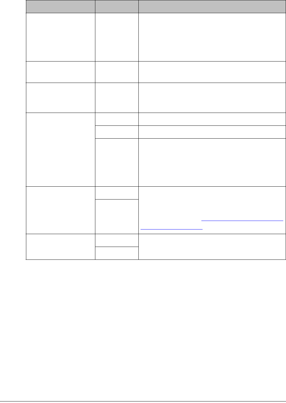
4-24 D9865 Satellite Receiver Installation and Operation Guide 4035197 Rev C
Note: If you enter an invalid frequency setting or a setting that does not correspond
to the selection, a pop-up message such as “Input value out of range" is displayed.
3. Press the green button (Save) to save your settings.
LO Freq1 Enter
number
If C-band application, set to 5.15 GHz (default).
If Ku-band single LNB, enter LO Freq. and set
LO Freq 2 and Crossover to 0.0.
If Ku-band dual LNB, enter LO Freq 1, LO Freq
2 and Crossover.
LO Freq2 Enter
number
Enter if Ku-band dual LNB application. LO Freq
2 > LO Freq 1.
Crossover Enter
number
Enter if Ku-Band dual LNB application. Used to
determine if LO Freq 1 or LO Freq 2 is used for
tuning.
LO Select
(Sets a 22 kHz tone
for Ku-band dual
LNB)
Off Switches 22 kHz tone off.
On Switches 22 kHz tone on.
Auto Sets 22 kHz tone to automatic.
If Downlink Freq < Crossover use LO1. The 22
kHz tone is Off.
If Downlink Freq > Crossover use LO2. The 22
kHz tone is On.
DiSEqC Enable Enables or disables Digital Satellite Equipment
Control. This must be enabled to control the
DiSEqC switch. LNB Power must be on to use
this setting. Refer to http://www.eutelsat.com/
satellites/4_5_5.html for more information.
Disable
DiSEqC Switch Off Selects a port on the LNB switch (if used).
A to P
Selection Options Description
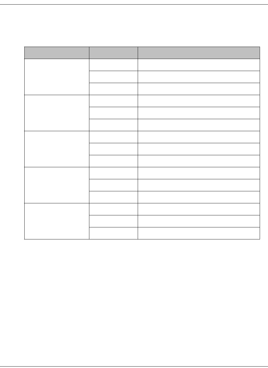
4035197 Rev C D9865 Satellite Receiver Installation and Operation Guide 4-25
Setting up LNB, Continued
LNB Power Settings
The following table displays the LNB Power settings:
LNB Power Setting NIT Contains Output LNB Voltage
Off Not received Off
HOff
VOff
18-H Not received 18 volts
H18 volts
V18 volts
13-V Not received 13 volts
H13 volts
V13 volts
H-NIT Not received 18 volts
H18 volts
V13 volts
V-NIT Not received 13 volts
H18 volts
V13 volts

4-26 D9865 Satellite Receiver Installation and Operation Guide 4035197 Rev C
Setting Up the Satellite Dish
To Set Up the Dish
The Dish Setup menu provides graphical assistance for dish positioning. This menu
can be set to two modes: User Mode (default) or Installer Mode. The User mode
allows you to select from stored Satellite Numbers, which are stored satellite
locations, as stored in the dish motor, but does not provide any dish control.
Proceed as follows to set up the dish:
1. From the Setup Menu, select Dish Setup and press OK. By default, the Dish
Setup screen is displayed in User mode.
2. The table at the top displays the current configurations.
3. The following table describes each of the options in User mode:
Selection Options Description
Satellite Number 1 to 255 Number identifying the saved satellite
location as defined by the dish motor
manufacturer.
User Action None No action is performed.
Goto Satellite Moves the dish to the selected pre-stored
satellite position. Satellite positions are stored
in the dish motor, if supported, not in the
receiver.
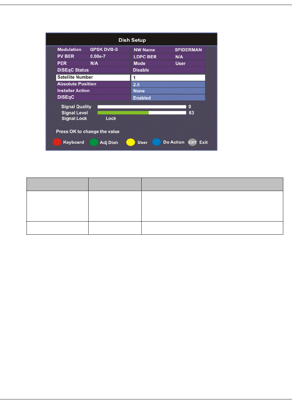
4035197 Rev C D9865 Satellite Receiver Installation and Operation Guide 4-27
Setting Up the Satellite Dish, Continued
4. Press the yellow button to switch between User and Installer modes. The
Installer mode is for Installers only.
5. The following table describes each of the available options for the Installer
mode:
Selection Options Description
Satellite Number 1 to 255 Number identifying the saved satellite
location as defined by the dish motor
manufacturer.
Absolute Position 0.0 to 75.0 Position of the satellite in degrees.
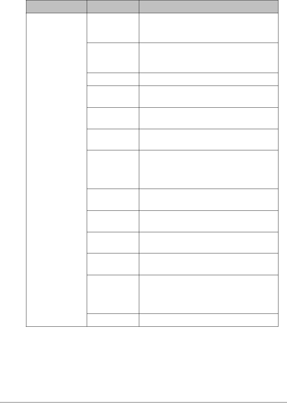
4-28 D9865 Satellite Receiver Installation and Operation Guide 4035197 Rev C
Installer Action Continuous
West
Movement
Moves the dish west until it reaches its limit.
Ensure that the dish can move to its limit
without any obstructions.
Continuous
East Movement
Moves the dish east until it reaches its limit.
Ensure that the dish can move to its limit
without any obstructions.
Stop Move Stops movement of the dish.
Goto Absolute
Position West
Moves the dish to the Absolute west position
set above.
Goto Absolute
Position East
Moves the dish to the Absolute east position
set above.
Goto Reference Moves the dish to a reference defined by the
dish motor manufacturer.
Goto Satellite Moves the dish to the selected pre-stored
satellite position. Satellite positions are stored
in the dish motor, if supported, not in the
receiver.
Store Satellite Stores the current dish position as a Satellite
Number, if supported by the dish motor.
Clear Limits Clears the dish east and west limits stored in
the dish motor.
Store East
Limits
Stores the current position as the east limit in
the dish motor.
Store West
Limits
Stores the current position as the west limit in
the dish motor.
Calculate
Position
Updates the position of the dish according to
the current position. For more information,
refer to the dish manual provided by the dish
manufacturer.
None No action is performed.
Selection Options Description
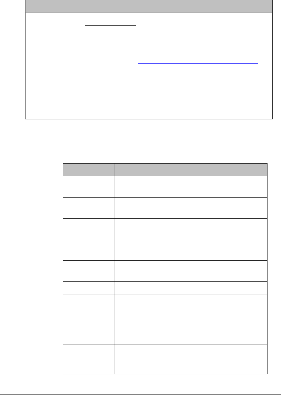
4035197 Rev C D9865 Satellite Receiver Installation and Operation Guide 4-29
6. Press the blue button (Do Action) to save and apply the settings to the receiver
until the next reboot.
7. The following table describes the view-only information on the Dish Setup
screen:
DiSEqC Enable Enables or disables Digital Satellite
Equipment Satellite Control.
Note: This must be enabled to control the
DiSEqC switch. LNB Power must be on to
use this setting. Refer to http://
www.eutelsat.com/satellites/4_5_5.html for
more information.
Before you can adjust the satellite position
using the Adjust Dish Position screen or a
signal tone, ensure that the LNB Power and
DiSEqC (in the Tuning/Preset screen) are
enabled.
Disable
Selection Options Description
Parameter Description
Modulation Indicates the modulation type for the received
signal.
LDPC BER Indicates the bit rate of the input stream of the
LDPC error correcting stage (DVB-S2 only).
Mode Indicates whether the current dish setup mode is
Installer or User. The mode can be changed by
pressing the yellow button.
NW Name Displays the network name.
PV BER Indicates the PV (Post-Viterbi) BER for the received
signal (DVB-S).
PER Indicates the current PER (Packet Error Rate).
DiSEqC Status Indicates whether the DiSEqC is enabled or
disabled.
Signal Quality Indicates the quality of the received signal,
associated with the Bit Error Rate, in the range
from 0 to 100.
Signal Level Displays the relative strength of the received RF
input signal. It is displayed in the range from 0 to
100.
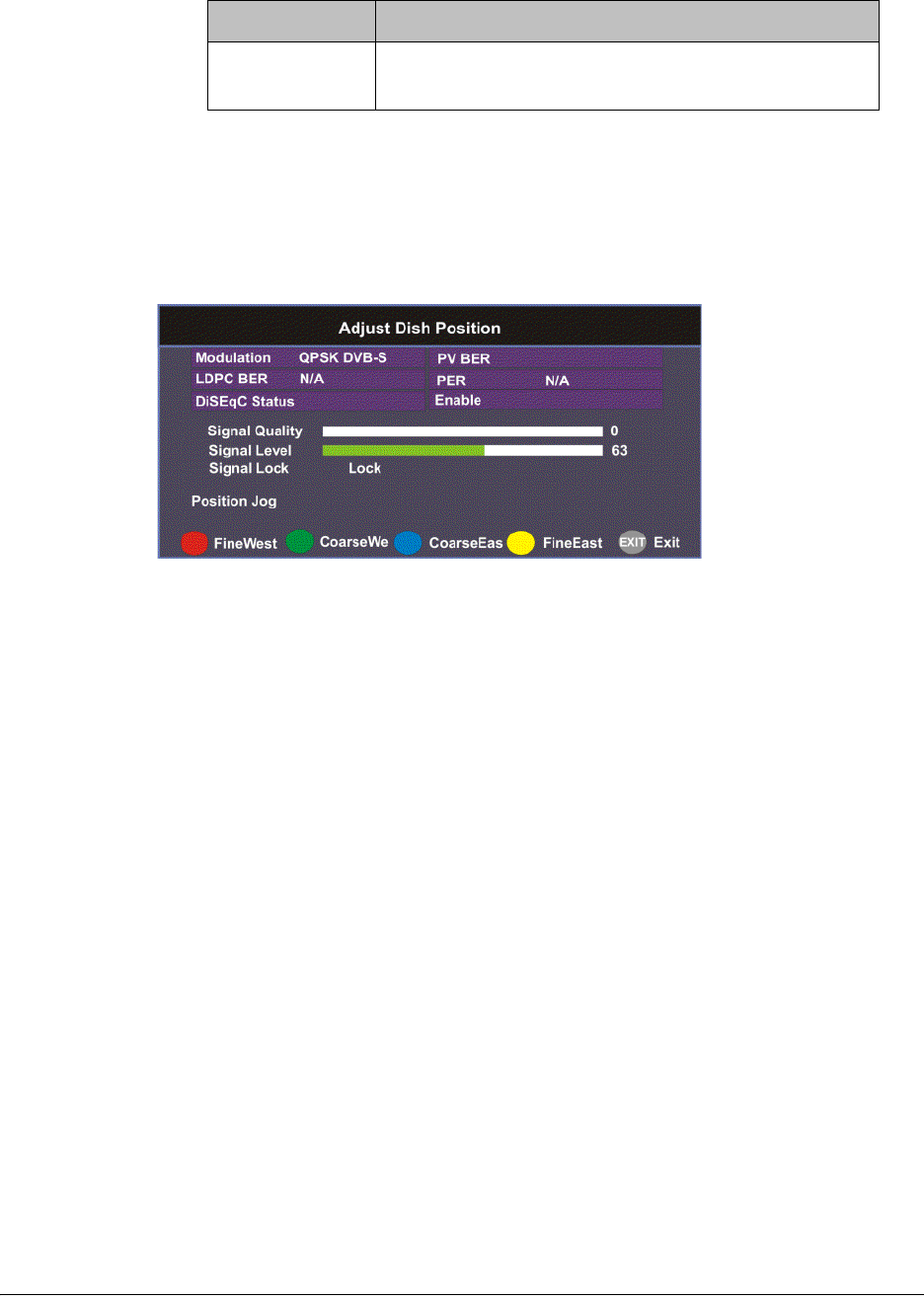
4-30 D9865 Satellite Receiver Installation and Operation Guide 4035197 Rev C
Adjusting the Satellite Position in Installer Mode
Note: To adjust the satellite position, the DiSEqC must be set to Enable.
1. On the Dish Setup screen, press the yellow button (Installer) to select Installer
mode.
2. Ensure the DiSEqC is set to Enable and then press the green button (Adj Dish).
3. Press the red or yellow button for fine west and east dish adjustment. Press the
green or blue button for coarse east and west dish adjustment.
Changing the Satellite Position in User Mode
To select a new satellite position on the Dish Setup menu:
1. Use the buttons to move to Satellite Number and press OK.
2. Enter the pre-stored satellite number you want to use in the range from 1 to 255,
and press OK.
3. Press to move down to User Action and press OK.
4. Press to choose Goto Satellite and press OK. The receiver is now tuned to the
selected satellite position.
5. Press MENU to move to the previous menu, or EXIT to go to video.
Signal Lock Indicates whether the receiver is synchronized with
the received RF signal.
Parameter Description
4035197 Rev C D9865 Satellite Receiver Installation and Operation Guide 4-31
Setting Up the Satellite Dish, Continued
Adjusting the Satellite position using Signal Tones
Dish alignment can be done using the audible signal adjustment tone. The
characteristics of the signal tone are shown in the table below. Align the dish to
achieve signal lock and then best signal quality.
Note: The signal adjustment tone automatically outputs as PCM audio type only,
regardless of the Digital Audio Preference set in Audio Setup.
Provided the RF cable is connected between the satellite receiver and the LNB,
Signal level displays a low number (typically less than 40). As the receiver achieves
Signal Lock, the Signal Level increases, and the tone changes from a slow repeating
beep to a steady tone. Once Signal Lock is obtained, align the dish to increase the
Signal Quality to the best possible value (up to a maximum of 10).
Signal Level and Signal Quality
The Signal Level and Signal Quality of the incoming signal are displayed both
numerically and graphically using bar graphs.
The Signal Level is associated with the RF input signal level. The Signal Level
display is continuously updated to indicate the relative strength of the received RF
input signal. It is displayed in the range from 0 to 100. Signal Level is displayed on
the Tuning / Preset and Dish Setup menus both numerically and graphically.
The Signal Quality (displayed in the range from 0 to 100) is associated with the Bit
Error Rate, and is a measure of the signal quality. Signal Quality is displayed both
numerically and graphically on the Dish Setup menu. To obtain the best signal
quality, adjust the dish position to obtain the highest Signal level and Signal
Quality possible.
Temporary, solar-related electromagnetic disturbances occur every year during the
spring and autumn months. These disturbances usually persist for several minutes
a day for approximately one week at this time. Your service provider can advise
you about channels that may be adversely affected.
To verify your satellite LNB antenna installation or improve signal reception, refer
to your antenna equipment installation manual, or contact your local service
provider.
Signal Lock/Quality Tone
No Signal Lock Slow repeating tone.
Signal Lock Steady tone.
Signal Lock +
increasing Signal
Quality
Steady tone increasing in pitch.

4-32 D9865 Satellite Receiver Installation and Operation Guide 4035197 Rev C
Setting Up the Satellite Dish, Continued
Signal Lock
The Signal Lock status is continuously updated to indicate whether the receiver is
synchronized with the received satellite RF signal. Signal Lock status is displayed
on the Preset / LNB Setup and Dish Setup menus.
If the receiver is able to synchronize to a carrier frequency and an MPEG stream is
present, Signal Lock displays Lock and the Signal LED on the receiver front panel
is on. If no carrier is detected, Signal Lock displays No Lock and the Signal LED is
off.
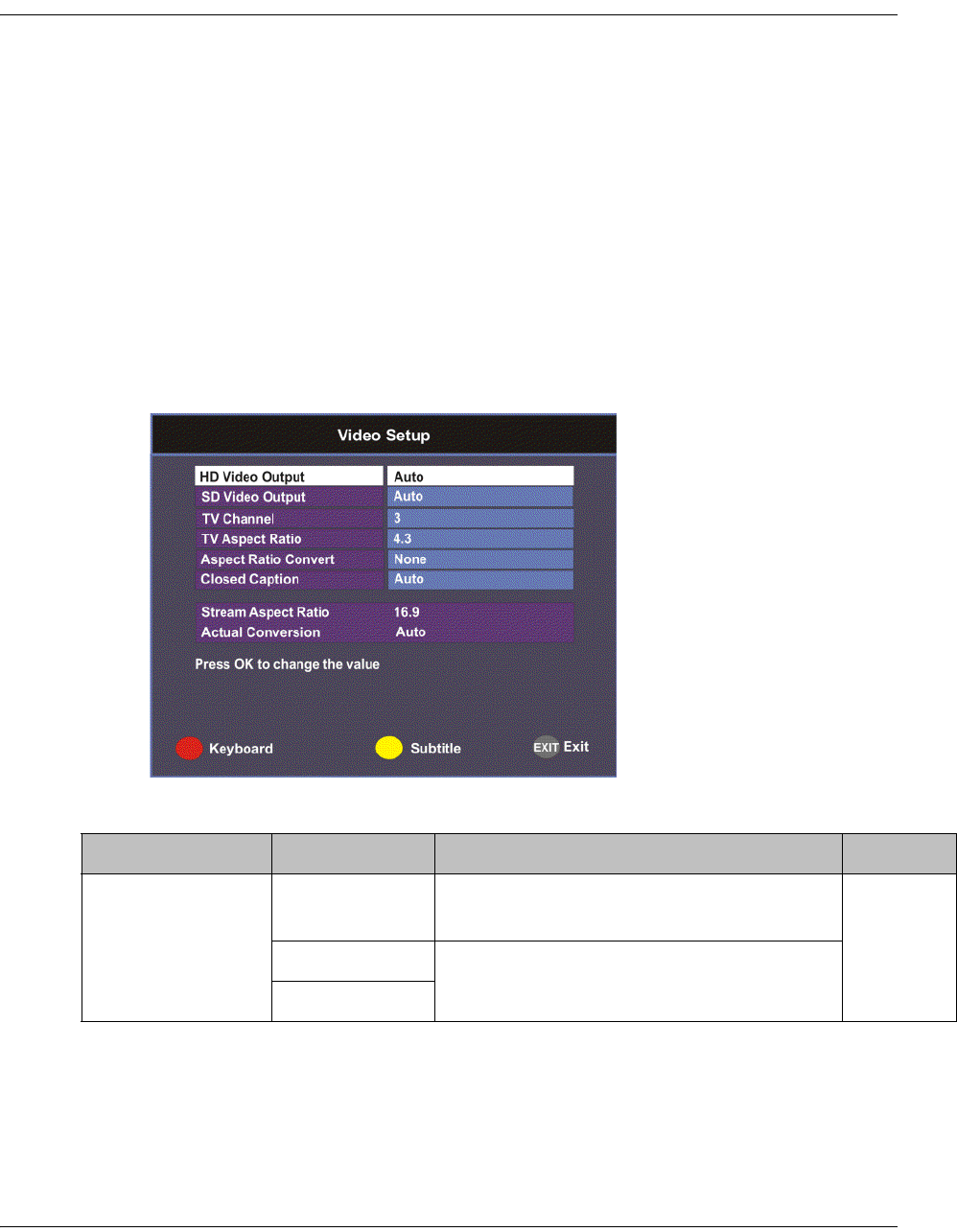
4035197 Rev C D9865 Satellite Receiver Installation and Operation Guide 4-33
Setting up the Video
Setting up the Video
The video format is set to the standard format for your country. If you attempt to
change the format of the source video signal, a warning message appears, to inform
you that if the fields are incorrectly configured, the display may not be viewable.
Check with your satellite or local service provider before changing the video
settings to ensure it is set correctly. Press OK to continue with the edit. Otherwise,
select Cancel.
Note: If an error was made when changing the video settings, you can set the TV
video format using the front panel. For more information, see Setting the TV Video
Format, on page 3-4.
Proceed as follows to set up the video information.
1. From the Setup Menu screen, select Video Setup and click OK.
2. The following table describes each of the options in the Video Setup screen.
Selection Options Description Default
HD Video Output Auto Receiver automatically detects correct HD
video format.
Auto
HD 1080i Sets the HD output video format.
HD 720p

4-34 D9865 Satellite Receiver Installation and Operation Guide 4035197 Rev C
SD Video Output Auto Receiver automatically detects correct SD
video format.
Depends
on TV
modulator
installed
PAL-B/G, PAL-
D, PAL-I
For 625-line systems.
PAL-M 525-line format for Brazil.
PAL-N (AR) 625-line format for Argentina.
NTSC, NTSC-J For 525-line systems.
TV Channel 3 or 4 for NTSC
21-69 for PAL
Sets TV channel for video display. 3 or 21,
depending
on TV
modulator
installed.
TV Aspect Ratio 4:3, 16:9 The aspect ratio of the intended TV
system.
4:3
Aspect Ratio
Convert
None This is the conversion that the receiver will
perform on the incoming signal for the
picture to be displayed correctly (i.e., to
correspond to the aspect ratio of your TV)
on your TV, based on your selection.
For the actual conversion performed, refer
to Actual Conversion Table, on page 4-35.
None
Auto
Auto AFD
16:9 L/B
4:3 P/B
14:9
4:3 CCO
16:9 SCALE
Closed Caption Auto This is the mode of closed-captioning to
use. if there are multiple in the stream.
Note: SA Custom is not supported when
telecine video coding is enabled.
Auto
SA Custom
EIA 708
Type 3
Type 4 SA
Type 4 ATSC
Reserved
DVB 157
Stream Aspect
Ratio
4:3, 16:9 This indicates the aspect ratio of the
incoming signal. This is read-only.
Selection Options Description Default
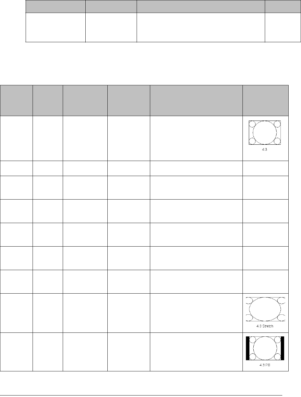
4035197 Rev C D9865 Satellite Receiver Installation and Operation Guide 4-35
Actual Conversion Table
The following table displays the actual conversion performed by the receiver
according to your TV Aspect Ratio selection and the affect on the picture displayed
on the TV screen.
Actual Conversion This is the type of (aspect ratio) conversion
the receiver will perform based on what
you have selected. This is read-only.
Selection Options Description Default
Stream TV
Aspect
Ratio
Aspect
Ratio
Conversion
Actual
Conversion
Description Image
4:3 4:3 None None Normal Picture
4:3 4:3 Auto None No conversion
4:3 4:3 16:9 L/B None Conversion is not possible.
Normal picture.
4:3 4:3 4:3 CCO None Conversion is not possible.
Normal picture.
4:3 4:3 4:3 P/B None Conversion is not possible.
Normal picture.
4:3 4:3 14:9 None Conversion is not possible.
Normal picture.
4:3 4:3 16:9 SCALE None Conversion is not possible.
Normal picture.
4:3 16:9 None None Picture is short & fat.
4:3 16:9 Auto 4:3 P/B Uses 4:3 P/B.
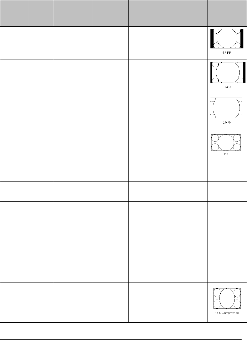
4-36 D9865 Satellite Receiver Installation and Operation Guide 4035197 Rev C
4:3 16:9 4:3 P/B 4:3 P/B 4:3 picture is centered in a
pillar-style box.
4:3 16:9 14:9 14:9 Compromises some up-
sampling. Some black bars
and cropping are visible.
4:3 16:9 16:9 SCALE 16:9 SCALE Vertically up-samples the
centre of the 4:3 picture and
crops the top and bottom of
the screen.
16:9 16:9 None None Normal
16:9 16:9 Auto None No conversion. Normal
picture.
16:9 16:9 16:9 L/B None Conversion is not possible.
Normal picture.
16:9 16:9 4:3 CCO None Conversion is not possible.
Normal picture.
16:9 16:9 4:3 P/B None Conversion is not possible.
Normal picture.
16:9 16:9 14:9 None Conversion is not possible.
Normal picture.
16:9 16:9 16:9 SCALE None Conversion is not possible.
Normal picture.
16:9 4:3 None None Picture appears tall and thin.
Stream TV
Aspect
Ratio
Aspect
Ratio
Conversion
Actual
Conversion
Description Image
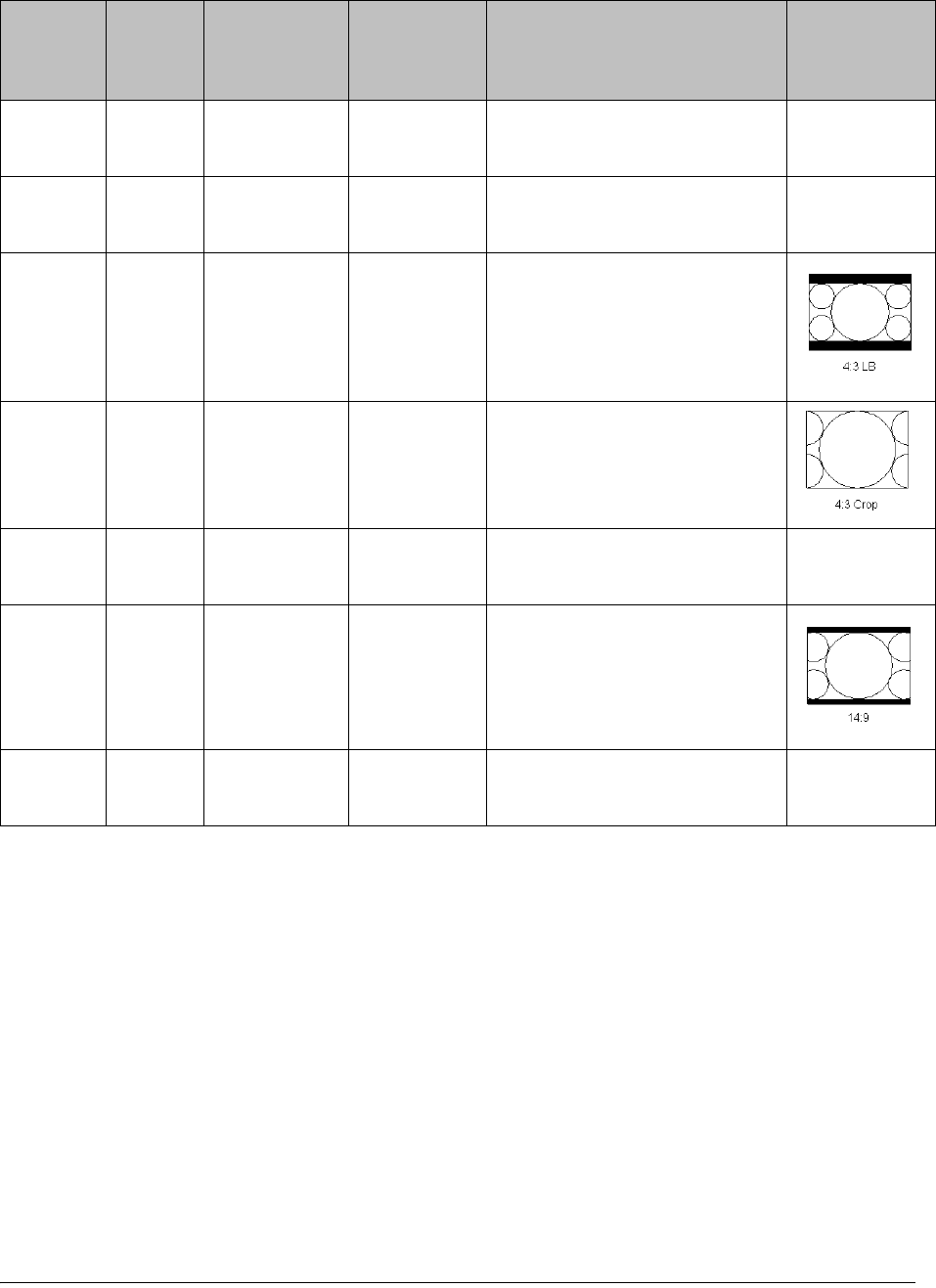
4035197 Rev C D9865 Satellite Receiver Installation and Operation Guide 4-37
4:3 16:9 16:9 L/B None Conversion is not possible.
Picture appears short and fat.
4:3 16:9 4:3 CCO None Conversion is not possible.
Picture appears short and fat.
16:9 4:3 16:9 L/B 16:9 L/B Vertically down-samples the
picture and applies black
bars at the top & bottom of
the screen.
16:9 4:3 4:3 CCO 4:3 CCO Horizontally up-samples the
centre portion of the picture
to fill the 720.
16:9 4:3 4:3 P/B None Conversion is not possible.
Picture appears tall and thin.
16:9 4:3 14:9 14:9 Compromises some up-
sampling. Some black bars
and some cropping are
visible.
16:9 4:3 16:9 SCALE None Conversion is not possible.
Picture appears tall and thin.
Stream TV
Aspect
Ratio
Aspect
Ratio
Conversion
Actual
Conversion
Description Image
4-38 D9865 Satellite Receiver Installation and Operation Guide 4035197 Rev C
Setting up the Video, Continued
Video Output Restrictions
The following table describes the nature of the Video Outputs given the source
video stream and selections that can be made by the user. The D9865 does not
provide video format conversion.
Source
Video
Format
User
Selected
SD Format
User
Selected
HD Format
Component &
HDMI
CVBS & TV-Out
SD-NTSC
(60Hz)
Auto or
NTSC
Auto 1080i 60Hz NTSC
1080i 1080i 60Hz NTSC
720p 720p 30Hz NTSC
PAL (50 Hz) Any Mismatch Mismatch
SD-PAL
(50Hz)
Auto or
PAL
Auto 1080i 50Hz PAL
1080i 10801 50Hz PAL
720p 720p 25Hz PAL
NTSC Any Mismatch Mismatch
1080i 60Hz Auto or
NTSC
Auto 1080i 60Hz NTSC
1080i 1080i 60Hz NTSC
720p 720p 30Hz NTSC
PAL Any Mismatch Mismatch
1080i 50Hz Auto or
PAL
Auto 1080i 50Hz PAL
1080i 1080i 50Hz PAL
720p 720p 25Hz PAL
NTSC Any Mismatch Mismatch

4035197 Rev C D9865 Satellite Receiver Installation and Operation Guide 4-39
Video formats that require a frame rate change from the original source stream are
blocked by a “Video Format Mismatch” banner and the video output is muted.
720p 30Hz Auto or
NTSC
Auto 720p 30Hz NTSC
1080i 1080i 60Hz NTSC
720p 720p 30Hz NTSC
PAL Any Mismatch Mismatch
720p 25Hz Auto or
PAL
Auto 720p 25Hz PAL
1080i 10801 50Hz PAL
720p 720p 25Hz PAL
NTSC Any Mismatch Mismatch
Source
Video
Format
User
Selected
SD Format
User
Selected
HD Format
Component &
HDMI
CVBS & TV-Out

4-40 D9865 Satellite Receiver Installation and Operation Guide 4035197 Rev C
Setting up Subtitles
Setting up Subtitles
The Subtitle Setup screen allows you to configure the type of subtitling (i.e., DVB or
Imitext displayed by the receiver, and how the receiver displays subtitling on TV.
Proceed as follows to set up subtitling:
1. From the Video Setup screen, press the yellow button (Subtitle).
2. The following table describes each of the options on the Subtitle Setup screen:
Selection Options Description Default
Subtitle Control Off No subtitles are displayed. Off
On Functions as an “Auto” setting. DVB
subtitles are displayed when only DVB
subtitles are transmitted on the channel,
and likewise, Imitext subtitles are
displayed when only Imitext subtitles are
transmitted on the channel. When both
DVB and Imitext subtitles are available on
the same channel, only DVB subtitles will
be displayed.
Imitext Displays only Imitext subtitles. For
example, if Imitext is selected, but both
DVB and Imitext subtitles are being
transmitted on the same channel, only
Imitext subtitles will be displayed.
DVB Displays only DVB subtitles. For example,
if DVB is selected, but both DVB and
Imitext subtitles are being transmitted on
the same channel, only DVB subtitles will
be displayed.
4035197 Rev C D9865 Satellite Receiver Installation and Operation Guide 4-41
Imitext Color (text
color)
Auto Displays text in the color transmitted by
the subtitling equipment.
Auto
Yellow Displays text in yellow.
White Displays text in white.
Imitext Shade
(background color)
Auto Displays background in same shade
transmitted by the subtitling equipment.
Auto
Shadow Applies an outline to the right side of each
text character. No background box is
applied to subtitles, i.e., text is visible
directly on top of video.
Opaque Applies a black box to each text character.
Semi Applies a semi-transparent box to subtitle
text.
None No shadow or outline is applied to subtitle
text.
Imitext Position Standard Subtitles appear on screen in same
position as output from other PowerVu
receivers.
Standard
Extended Subtitles are positioned on screen
according to the Imitext (extended)
specification.
Subtitle Language Available
languages
Select from any one of the available
languages.
eng
(English)
Selection Options Description Default
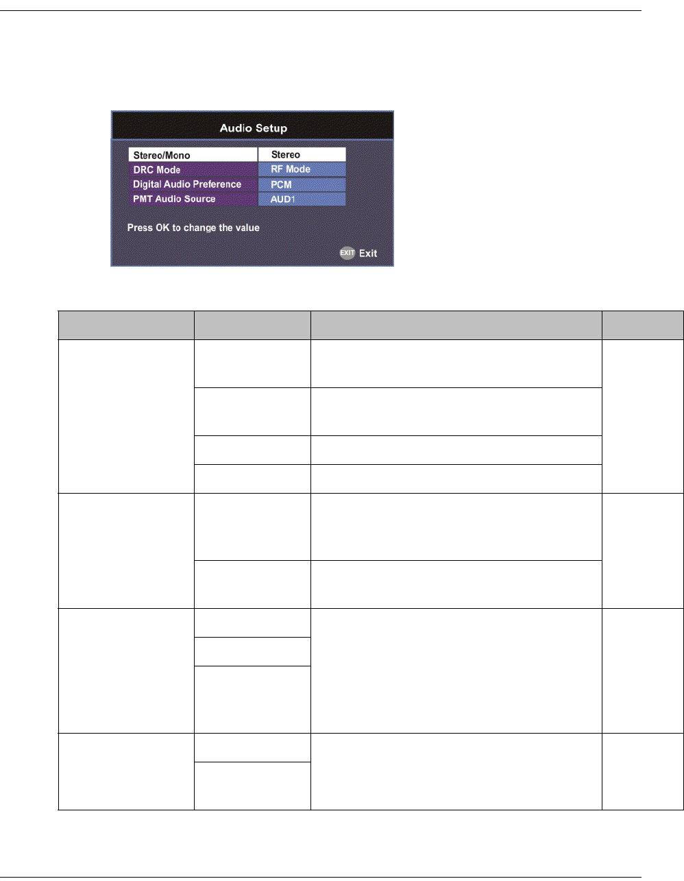
4-42 D9865 Satellite Receiver Installation and Operation Guide 4035197 Rev C
Setting up Audio
Setting up the Audio
Proceed as follows to select the audio source.
1. From the Setup Menu screen, select Audio Setup and click OK.
2. The following table describes each of the options:
Selection Options Description Default
Stereo/Mono Stereo Left and right channels are output on L
and R respectively.
Stereo
Mixed Left and right channels are combined and
output on both L and R.
L-MONO Left channel is output on L and R.
R-MONO Right channel is output on L and R.
DRC Mode RF Mode This setting is normally used for analog
cable modulators, when limited dynamic
range is desired.
RF Mode
Line Mode Setting used when full dynamic range is
allowed.
Digital Audio
Preference
PCM Set the compressed audio type.
For more information on the settings, see
the table in Digital Audio Preference
Settings, on page 4-43.
PCM
Dolby Digital
Compressed
(Dolby Digital
Plus)
PMT Audio Source None Select the PMT Audio Source for the audio
channel.
AUD1
AUD1 to
AUD64

4035197 Rev C D9865 Satellite Receiver Installation and Operation Guide 4-43
Setting up Audio, Continued
Digital Audio Preference Settings
The following table displays the effects of Dolby Audio Preference setting on audio
outputs, based on the type of audio being decoded:
Input/
Output
Digital Audio Preference
PCM Dolby Digital Compressed
S/PDIF HDMI
MPEG LA
(MPEG1 and
MPEG2)
PCM PCM PCM PCM
Dolby Digital PCM Dolby Digital
(follows IEC 61937)
Dolby Digital
(follows IEC
61937)
Dolby Digital
(follows IEC
61937)
Dolby Digital Plus
(< 1.5 Mbps)
PCM Dolby Digital
(follows IEC 61937)
Dolby Digital
Plus (No over-
clocking,
follows SMPTE-
338)
Dolby Digital
Plus (over-
clocking x4,
follows IEC
61937)
Dolby Digital Plus
(>= 1.5 Mbps)
PCM Dolby Digital
(follows IEC 61937)
Dolby Digital
(follows IEC
61937)
Dolby Digital
(follows IEC
61937)
MPEG2 AAC,
MPEG4 (AAC and
HEAAC v1 and
v2)
PCM MPEG2 AAC,
MPEG4 (AAC and
HEAAC)
(follows IEC 61937)
MPEG2 AAC,
MPEG4 (AAC
and HEAAC)
(follows IEC
61937)
MPEG2 AAC,
MPEG4 (AAC
and HEAAC)
(follows IEC
61937)
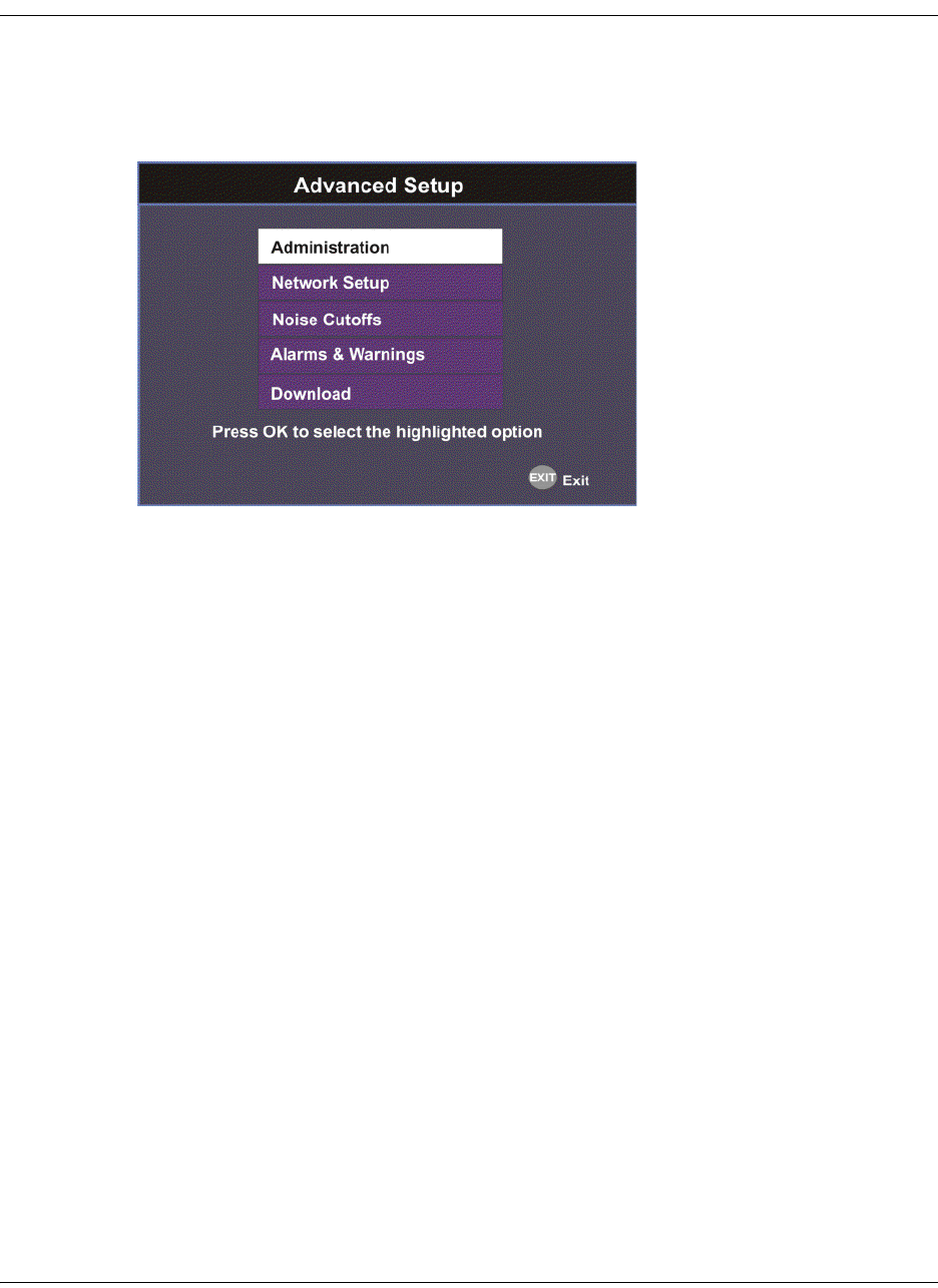
4-44 D9865 Satellite Receiver Installation and Operation Guide 4035197 Rev C
Advanced Setup
To View the Advanced Setup Menu
Proceed as follows to view the Advanced Setup screen.
From the Setup Menu screen, select Advanced Setup and press OK.
The function for the available sub-menus is as follows:
• Administration
From this menu, you can display and control the Lock level, date and time, and
other settings.
• Network Setup (D9865D only)
From this menu, you can configure the receiver for Ethernet operation.
• Noise Cutoffs
From this menu, you can set the noise thresholds.
• Alarms & Warnings
From this menu, you can configure alarm and warning settings.
•Download
From this menu, you can control and view the status of a code download.
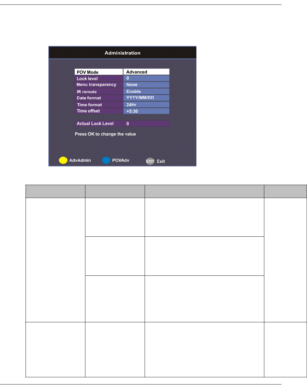
4035197 Rev C D9865 Satellite Receiver Installation and Operation Guide 4-45
Setting up Advanced User Settings
To Set Up the Advanced User Settings
Proceed as follows to set up the advanced user settings:
1. From the Advanced Setup screen, select Administration and press OK.
2. The following table describes each of the options:
Selection Options Description Default
POV Mode Standard Configures the network controls to the
following pre-defined settings:
CA Mode - Std
Acquisition Mode - Basic
Standard
Open Configures the network controls to the
following pre-defined settings:
CA Mode - Open
Acquisition mode - Auto
Advanced Enables the POVAdv menu option,
allowing you to customize the CA
Mode and Acquisition settings. For
more information, see Setting up POV
Mode, on page 4-50.
Lock level 0 to 3 Restricts access and prevents
unauthorized changes to receiver
settings.
For details on changing the lock level,
see Changing the Lock Level, on
page 4-47.
0

4-46 D9865 Satellite Receiver Installation and Operation Guide 4035197 Rev C
Menu
transparency
None, 25%, 50%,
75%, 90%
Set the transparency level of the menus
displayed on-screen.
For example, if set to None, menus are
solid and the video appears behind the
menus. If set to 25%, menus are clear
and the video is visible through the
menus.
None
IR remote Enable Set to Enable to control the receiver
using the remote control. By default,
the receiver is shipped with the remote
control enabled.
Note: The EPG functions are only
available using the IR remote control.
Enable
Disable Set to Disable if you want to disable
the remote control and use the front
panel controls only.
Date Format YYYY/MM/DD,
DD/MM/YYYY,
MM/DD/YYYY
Current date information is displayed
in the Active Alarm and Active
Warning screens.
YYYY/MM/
DD
Time format 24 Hr, 24 Hr
SuspendZero, 12
Hr, 12 Hr
SuspendZero
Time information is displayed in the
Active Alarm and Active Warning
screens.
Time information is normally broadcast
as part of the transmitted digital signal,
and is usually the broadcaster local
time relative to Greenwich Mean Time
(GMT).
24 Hr
Time offset Adjusted in one
hour increments,
from -12:00 to
+13:00, and GMT.
Displays the time zone offset instead of
the true local time. If the current
broadcast time is not your local time,
you must change this time setting.
+05:30
Actual Lock Level Displays the current lock level.
Adv Admin Displays the Advanced Administration
screen. For more information, see
Changing the Lock Level Password,
on page 4-48.
Selection Options Description Default

4035197 Rev C D9865 Satellite Receiver Installation and Operation Guide 4-47
Setting up Advanced User Settings, Continued
Changing the Lock Level
Receiver lock levels are password-protected. When an attempt is made to change
the lock level setting, a password prompt is displayed. After the correct password is
entered, you can change the lock level setting.
If the incorrect password is entered (any lock level setting), a message box appears
on-screen to confirm an invalid password entry, and access to the locked options
are denied.
Note: The default password is 1234.
For details on the four lock levels, see D9865 Satellite Receiver Lock Levels, on
page C-2.
Proceed as follows to change the lock level:
1. In the Administration menu, scroll to select Lock Level and press OK. The PIN
Entry screen appears.
2. Press OK to enter the current password using the numeric keypad on the
remote control and press OK. For security reasons, a default character is
substituted for each button pressed.
3. Use to select a valid lock level (lock levels are displayed from 0 to 3) and
then press OK. The default setting is 0. The Actual Lock Level parameter below
is updated to the new lock level.
Menu options change color (view-only) if disabled by the current lock level
setting.
Important: A virtual channel displayed for 20 seconds or more automatically
becomes the current (Last) channel. As Lock Level 3 disables most Lock Level 0
functions (including channel changes), perform this action before changing the
current Lock Level setting to 3.
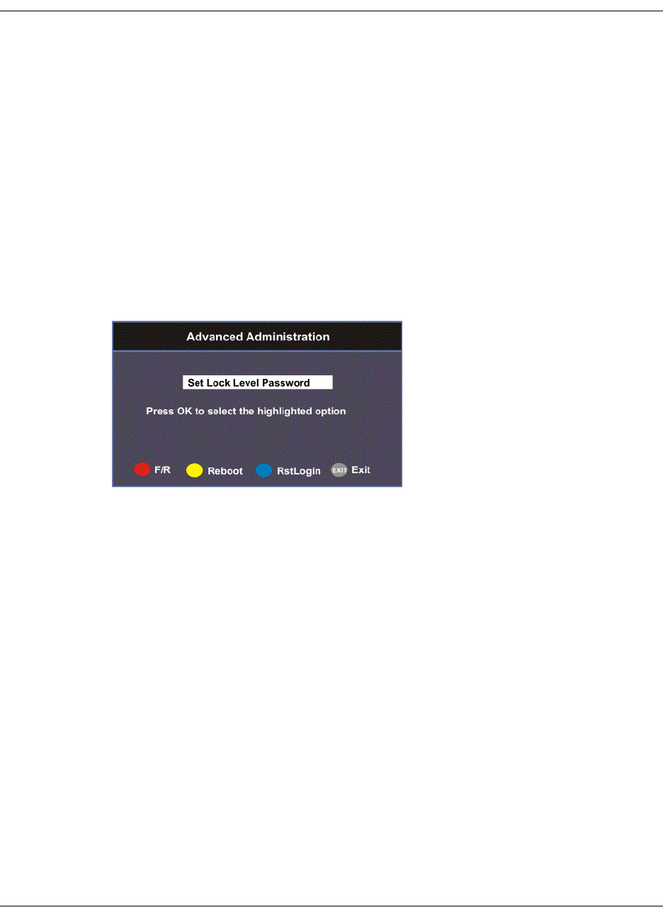
4-48 D9865 Satellite Receiver Installation and Operation Guide 4035197 Rev C
Changing the Lock Level Password
The Advanced Administration sub-menu allows you to change the following:
• Set Lock Level Password - to change the current lock level password (1234).
• Factory Reset - to restore the receiver to factory default settings.
Changing the Lock Level Password
A unique lock level password (4-digit password) protects the current receiver
settings against unauthorized changes. When changing the password, record and
keep this number in a secure location. The default password is 1234.
Important: Proceed with caution when changing the password as this operation
cannot be undone. If the password is lost or is unavailable, contact Cisco customer
support.
To change the lock level password:
1. From the Administration screen, press the yellow button (Adv Admin).
2. Select Set Lock Level Password and press OK.
3. Press OK to enter the current password and press OK. For security, a default
character is substituted for each button pressed.
4. Press OK to enter the new password, any number from 0 to 9, and press OK.
5. Press OK to enter the new password again for password confirmation and press
OK. A message appears informing you that the password was changed
successfully.
Note: If the password is lost or is unavailable, contact Cisco customer support.

4035197 Rev C D9865 Satellite Receiver Installation and Operation Guide 4-49
Changing the Lock Level Password, Continued
Performing a Factory Reset
The Factory Reset (F/R) is used for restoring the receiver’s factory presets (defaults).
When activated, the current receiver settings are replaced by the default settings.
After the factory defaults are restored, you can change the receiver settings as
required.
To restore the factory default settings using the remote control:
1. From the Advanced Administration screen, press the blue button (F/R).
2. Select Yes to reset the receiver and restore to factory defaults. Select No to cancel
the operation.
Following a factory reset, the receiver returns to Standby mode. Wait for the
flashing front panel LED, and then press the Display button on the remote control
or front panel, followed by the Menu button to return to the Main Menu.
Rebooting the Receiver
If you need to reboot the receiver for any reason, you can perform this function
without changing any settings.
To reboot the receiver:
1. From the Advanced Administration screen, press the yellow button (Reboot). A
message appears confirming that you want to reboot the receiver.
2. Select Yes to reboot. Otherwise, select No.
Resetting the Web GUI Login Information
The Reset Login (RstLogin) is used for resetting the username and password used
for Web GUI login to its default values. The default username is admin and the
default password is localadmin.
To reset the login:
1. From the Advanced Administration screen, press the blue button (RstLogin). A
message appears confirming that you want to reset the password to its default
values.
2. Select Yes. Otherwise, select No.
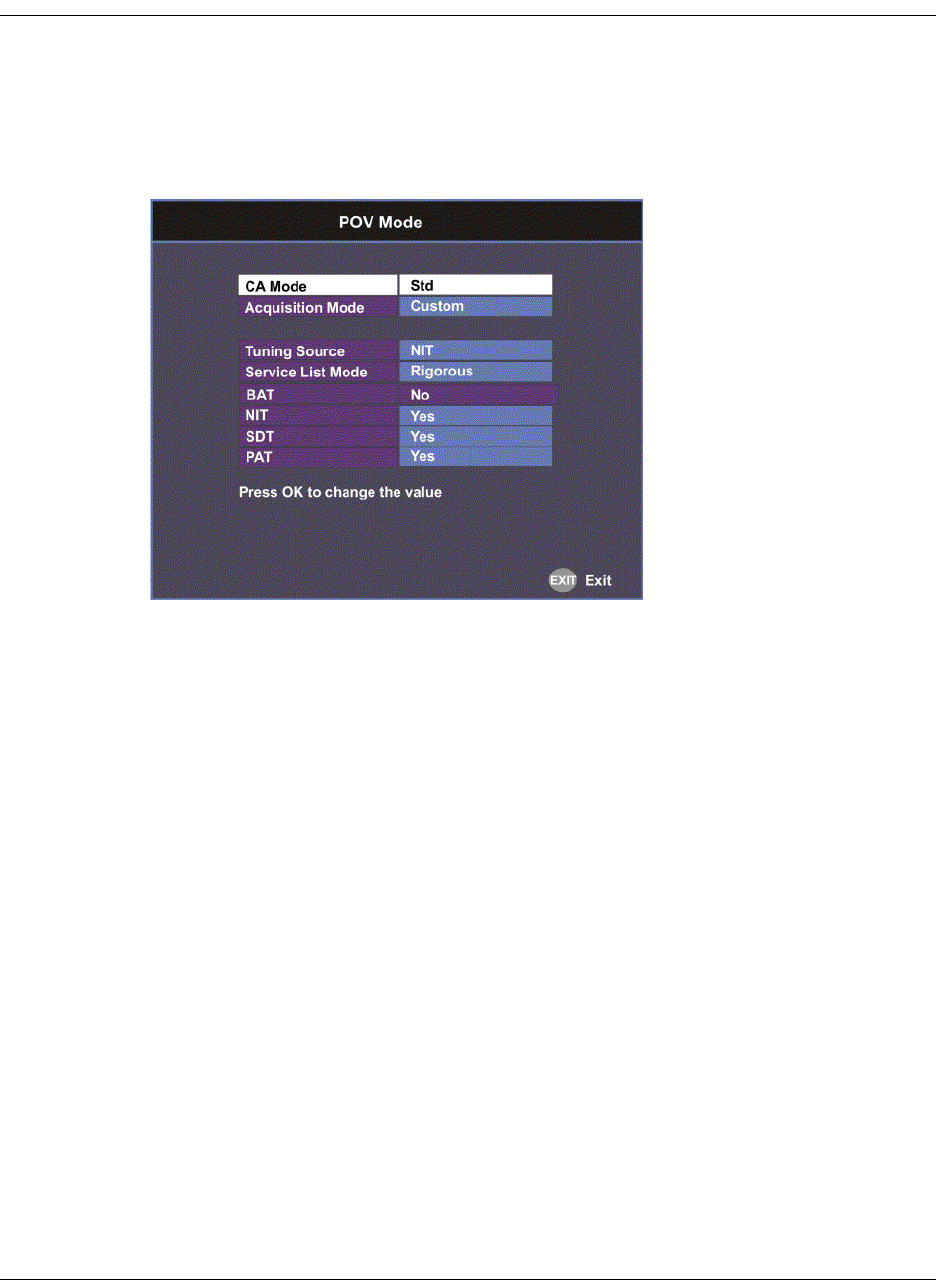
4-50 D9865 Satellite Receiver Installation and Operation Guide 4035197 Rev C
Setting up POV Mode
To Set Up the POV Mode
Proceed as follows to configure the POV Mode:
Note: Ensure the POV Mode setting is set to Advanced.
1. From the Administration screen, press the blue button (POVAdv).
2. Select the Conditional Access type (CA Mode) that determines which programs
can be viewed via the satellite receiver. Select Std (preferred) or Open. The
default is Std.
Important: In Open mode, the receiver ignores inconsistent scrambling
descriptions within the signal. Operating in this mode may cause the decoder
not to respond to certain advanced uplink controlled features, such as service
replacement.
3. Set the Acquisition Mode used to build channel lists from allowed service lists
(Basic, Auto, or Custom). Select Custom to customize the tables used to obtain
tuning and channel lists.
4. If the Acquisition Mode was set to Custom, you can set the Tuning Source to
indicate whether the receiver is tuned to the received signal using the NIT or a
Preset. The default is NIT.

4035197 Rev C D9865 Satellite Receiver Installation and Operation Guide 4-51
Setting up POV Mode, Continued
5. The Service List Mode indicates which tables are used to obtain tuning and
channel lists. This only applies when Acquisition Mode is set to Custom. Select
Rigorous if all default settings must be present in the received signal. Select
Degraded and only the table parameters present in the received signal will be
used to install the receiver.
The following table displays the default settings for the allowed service lists and
frequency tuning settings.
Allowed Service Lists Auto Basic Custom
BAT No No No
NIT Yes Yes No
SDT Yes No No
PAT Yes No Yes
Tuning Source NIT NIT Preset

4-52 D9865 Satellite Receiver Installation and Operation Guide 4035197 Rev C
Network Setup
To View the Network Setup Menu
Proceed as follows to view the Network Setup screen (D9865D only).
From the Advanced Setup menu, select Network Setup and press OK.
The function for the available sub-menus is as follows:
•IP Setup
From this menu, you can configure the receiver for Ethernet operation.
•Unicast IP Setup
From this menu, you can configure network destinations for unicast
transmission.
•Multicast IP Setup
From this menu, you can configure network destinations for multicast
transmission.
•SNMP Setup
From this menu, you can configure the password to read and write data to a
device. You can also configure trap destinations.
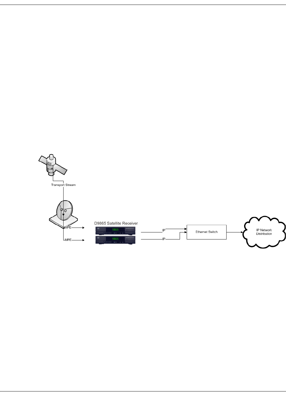
4035197 Rev C D9865 Satellite Receiver Installation and Operation Guide 4-53
Configuring IP Setup
Setting up the IP Information
The IP Setup screen allows you to set the parameters for communicating with other
equipment via the Ethernet Data and Management ports for MPE applications. The
D9865 supports unicast and multicast IP streaming. There are two Ethernet ports
(Port 1 and Port 2). Click the blue button (Next Port) in the IP Setup menu to toggle
between the two ports.
Note: Only Port 1 is available for this release.
MPE Output
The Multiprotocol Encapsulation (MPE) output provides a means to carry packet
oriented IP protocols on top of a transport stream. The MPE output receives IP
packets from the transport stream and the IP data can be sent through an Ethernet
switch to an IP router or directly to a receiving device.
The diagram below shows an example of the D9865 receiver used in an MPE
application.
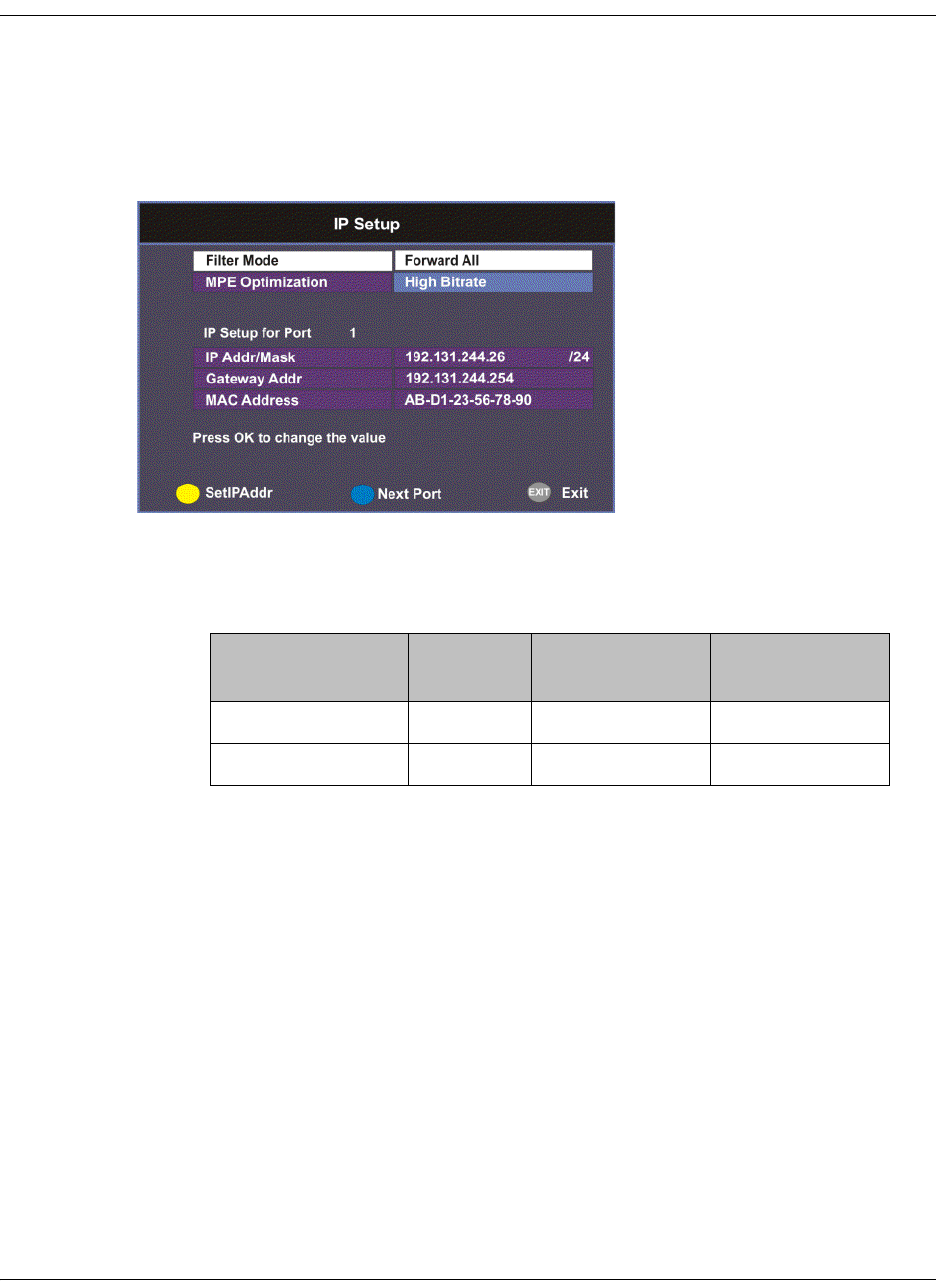
4-54 D9865 Satellite Receiver Installation and Operation Guide 4035197 Rev C
Configuring IP Setup, Continued
Setting the Filter Mode
The filter mode sets the multicast forwarding for MPE data output.
Proceed as follows to set up the filter mode:
1. From the Advanced Setup screen, select IP Setup and press OK.
2. The Filter Mode sets whether all the MPE data is forwarded (Forward All). It
can forward up to 5 PIDs at the maximum bit rates shown in the following table.
Otherwise, select Forward None.
3. Set the MPE Optimization setting. Select High Bitrate (default) to accumulate
the IP packets before they are processed in short bursts, increasing the allowable
bit rate of MPE data. Select Low Jitter to emit the IP packets in a constant
stream, resulting in low latency.
MPE Bit Rate No
Decoding
5 Mbps SD
Video Decoded
20 Mbps HD
Video Decoded
Multicast 30 Mbps 20 Mbps 15 Mbps
Unicast 20 Mbps 15 Mbps 10 Mbps
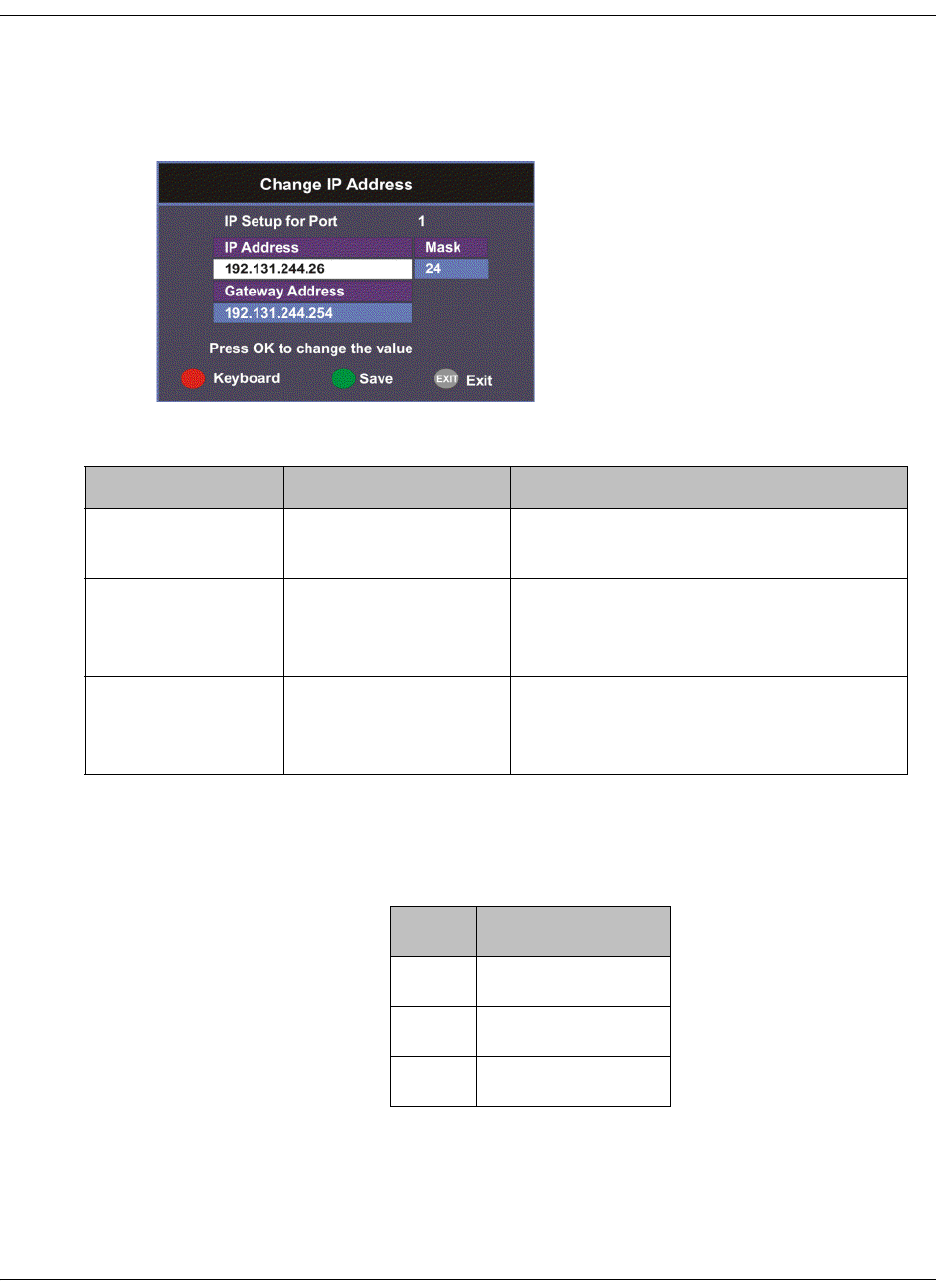
4035197 Rev C D9865 Satellite Receiver Installation and Operation Guide 4-55
Configuring IP Setup, Continued
Editing an IP Address
Proceed as follows to edit the Network IP Address:
1. From the IP Setup screen, press the yellow button (SetIPAddr).
2. The following table describes each of the options:
The Network Address, Prefix Mask, and Gateway Address should be changed
together, as a group. The following table shows the most commonly used
Subnet mask values to enter for a chosen IP address mask, which will depend on
the size of your network.
Note: Only Port 1 is available for this release.
Selection Options Description
IP Address 12 digits in length
(###.###.###.###)/
Sets the IP Address for its participation
in a Network environment.
Mask 8 to 32 Sets the Subnet Mask for its
participation in a Network
environment.
Gateway Address 12 digits in length
(###.###.###.###)
Sets the Network Gateway Address on
the Network, used to expose the
receiver to a WAN.
Mask Subnet Mask
8 255.0.0.0
16 255.255.0.0
24 255.255.255.0

4-56 D9865 Satellite Receiver Installation and Operation Guide 4035197 Rev C
Setting the Unicast IP Address
Viewing the Unicast IP
Unicast transmission is used to send messages to a specific address. You can specify
up to six single network destinations. The Gateway address is necessary if the
network address is not on a local network.
Proceed as follows to view the Unicast IP addresses:
1. From the Network Setup screen, select Unicast IP Setup and click OK.
The Unicast IP Setup screen lists all the IP addresses and its Gateway addresses that
are participating in a Network environment.
Adding a Unicast IP Address
Proceed as follows to add a Unicast IP Address:
1. From the Unicast IP Setup screen, press the green button (Add) to add a new
address.
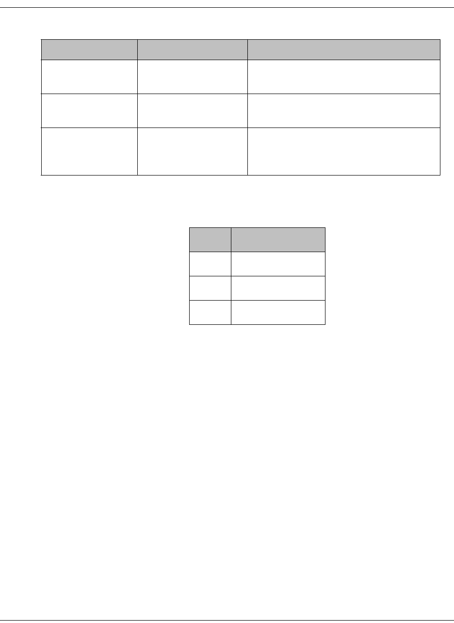
4035197 Rev C D9865 Satellite Receiver Installation and Operation Guide 4-57
Setting the Unicast IP Address, Continued
2. The following table describes each of the options:
The Network Address, Mask, and Gateway Address should be changed together, as
a group. The following table shows the most commonly used Subnet mask values to
enter for a chosen IP address mask, which will depend on the size of your network.
3. Select the green button (Save).
Editing a Unicast IP Address
1. In the Unicast IP Setup screen, scroll to the unicast IP you want to edit using the
buttons.
2. Press OK. The Edit/Delete Unicast IP screen is displayed.
3. Select Edit or press the blue button (Edit). The Add/Edit Unicast IP screen is
displayed.
4. Make the necessary changes.
5. Select the green button (Save).
Deleting a Unicast IP Address
1. In the Unicast IP Setup screen, scroll to the unicast IP you want to delete using
the buttons.
2. Press OK. The Edit/Delete Unicast IP screen is displayed.
3. Select Delete or press the red button (Delete). A message appears to confirm the
deletion.
4. Press OK.
Selection Options Description
Network Address 12 digits in length
(###.###.###.###)
Sets the IP Address for its participation
in a Network environment
Mask 8 to 32 Sets Subnet Mask for its participation in
a Network environment.
Gateway Address 12 digits in length
(###.###.###.###)
Sets the Network Gateway Address on
the Network, used to expose the
receiver to a WAN.
Mask Subnet Mask
8 255.0.0.0
16 255.255.0.0
24 255.255.255.0
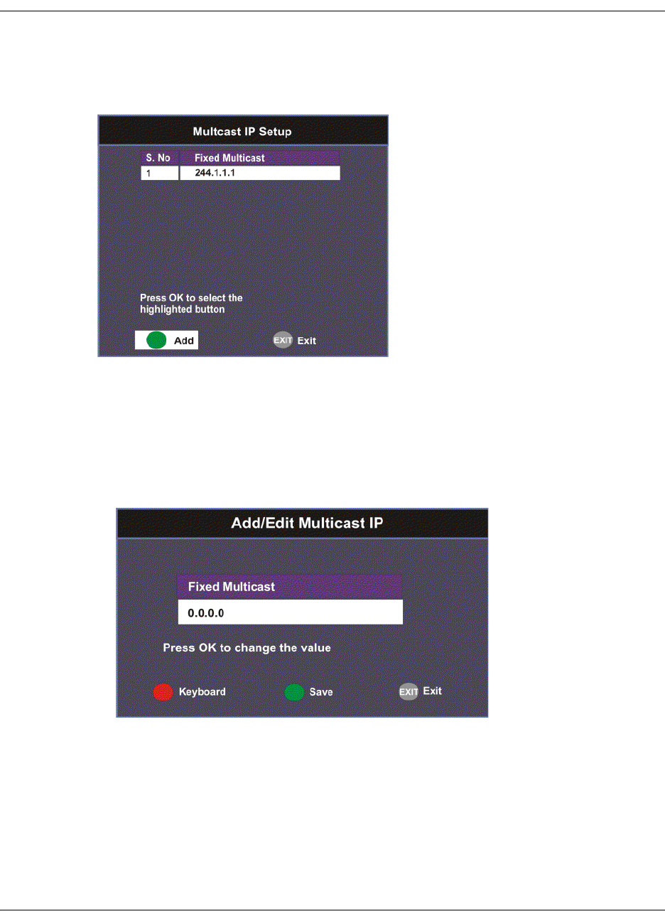
4-58 D9865 Satellite Receiver Installation and Operation Guide 4035197 Rev C
Setting the Multicast IP Address
Viewing the Multicast IP Addresses
Proceed as follows to view the Multicast IP addresses:
1. From the Network Setup screen, select Multicast IP Setup and click OK.
The Multicast IP Setup screen lists all the fixed multicast destination IP addresses.
Adding a Multicast IP Address
Proceed as follows to add a Multicast IP Address:
1. From the Multicast IP Setup screen, press the green button (Add) to add a new
address.
2. Set the multicast destination IP address, in the range from 0 to 255 for each of the
four fields in the following format: ###.###.###.###. For example, 225.1.1.1.
3. Press the green button (Save) to save your changes.

4035197 Rev C D9865 Satellite Receiver Installation and Operation Guide 4-59
Setting the Multicast IP Address, Continued
Editing a Multicast IP Address
1. In the Multicast IP Setup screen, scroll to the multicast IP you want to edit using
the buttons.
2. Press OK. The Edit/Delete Multicast IP screen is displayed.
3. Select Edit or press the blue button (Edit). The Add/Edit Multicast IP screen is
displayed.
4. Make the necessary changes.
5. Select the green button (Save).
Deleting a Multicast IP Address
1. In the Multicast IP Setup screen, scroll to the multicast IP you want to delete
using the buttons.
2. Press OK. The Edit/Delete Multicast IP screen is displayed.
3. Select Delete or press the red button (Delete). A message appears to confirm the
deletion.
4. Press OK.
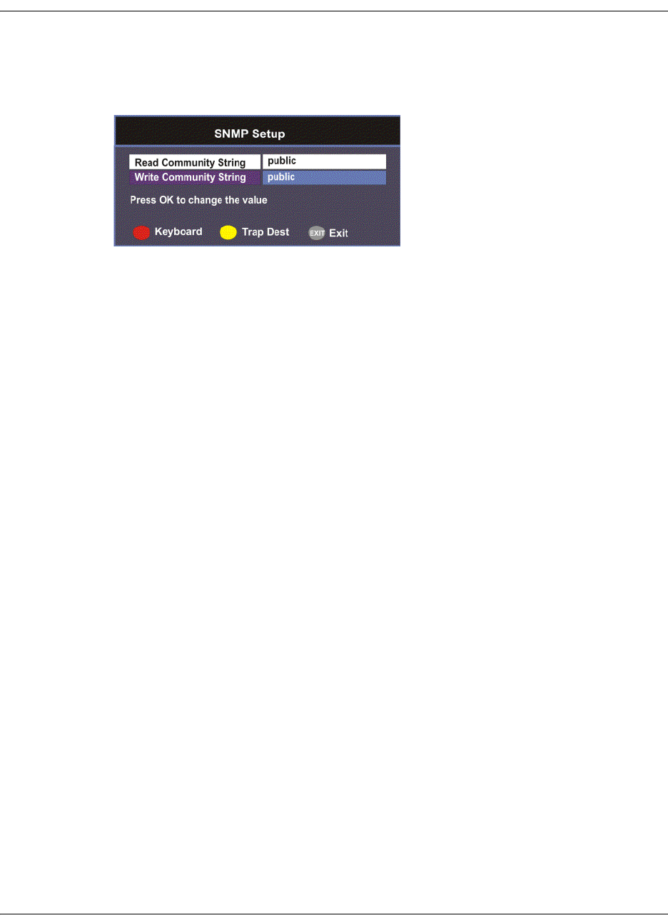
4-60 D9865 Satellite Receiver Installation and Operation Guide 4035197 Rev C
Setting up SNMP
Configuring SNMP Setup
Proceed as follows to configure SNMP:
1. From the Network Setup screen, select SNMP Setup and press OK.
2. Set the Read/Write Community String to public or a custom string. The SNMP
Community Read/Write is used when communicating with a device within an
SNMP environment. These commands allow you to set the password to read
and write data to a device to display diagnostics traps/alarms. The default
community string is public. To set a custom community string, enter an
alphanumeric character string up to 31-characters in length identifying the
password for the device.
Note: The community string is case-sensitive.

4035197 Rev C D9865 Satellite Receiver Installation and Operation Guide 4-61
Setting up Trap Destinations
Viewing Trap Destinations
Note: You can assign up to 10 entries to the Trap Destination and Community
String fields.
Proceed as follows to view trap destinations:
From the SNMP Setup screen, press the yellow button (Trap Dest) to view trap
destinations.
The Trap Destination Setup screen displays a list of trap destination addresses and
the associated community string.

4-62 D9865 Satellite Receiver Installation and Operation Guide 4035197 Rev C
Setting up Trap Destinations, Continued
Adding Trap Destinations
Proceed as follows to add trap destinations:
1. From the Trap Destination Setup screen, press the green button (Add) to add a
trap destination address.
2. The following table describes each of the available options:
3. Click the green button (Save) to save the changes.
Editing/Deleting Trap Destinations
Proceed as follows to edit/delete trap destinations.
1. In the Trap Destination Setup screen, select the trap destination address you
want to edit or delete and press OK.
2. Press the blue button (Edit) to edit the address. Press the red button (Delete) to
remove the address from the Trap Destination list.
3. If you pressed the blue button, you can edit the Trap Destination Address and
Community String and press the green button (Save) to save your changes.
4. If you pressed the red button (Delete), a warning message appears. Press OK to
delete the selected trap destination entry. Otherwise, press Exit.
Selection Options Description
Trap Destination
Address
Up to 12 digits in
length (e.g.,
155.128.100.200).
Enter the destination for SNMP trap
messages for events (i.e., fault
messages).
Community String public or custom
string. Up to 31
characters
Set the community string for the trap IP
address above. The default is public.
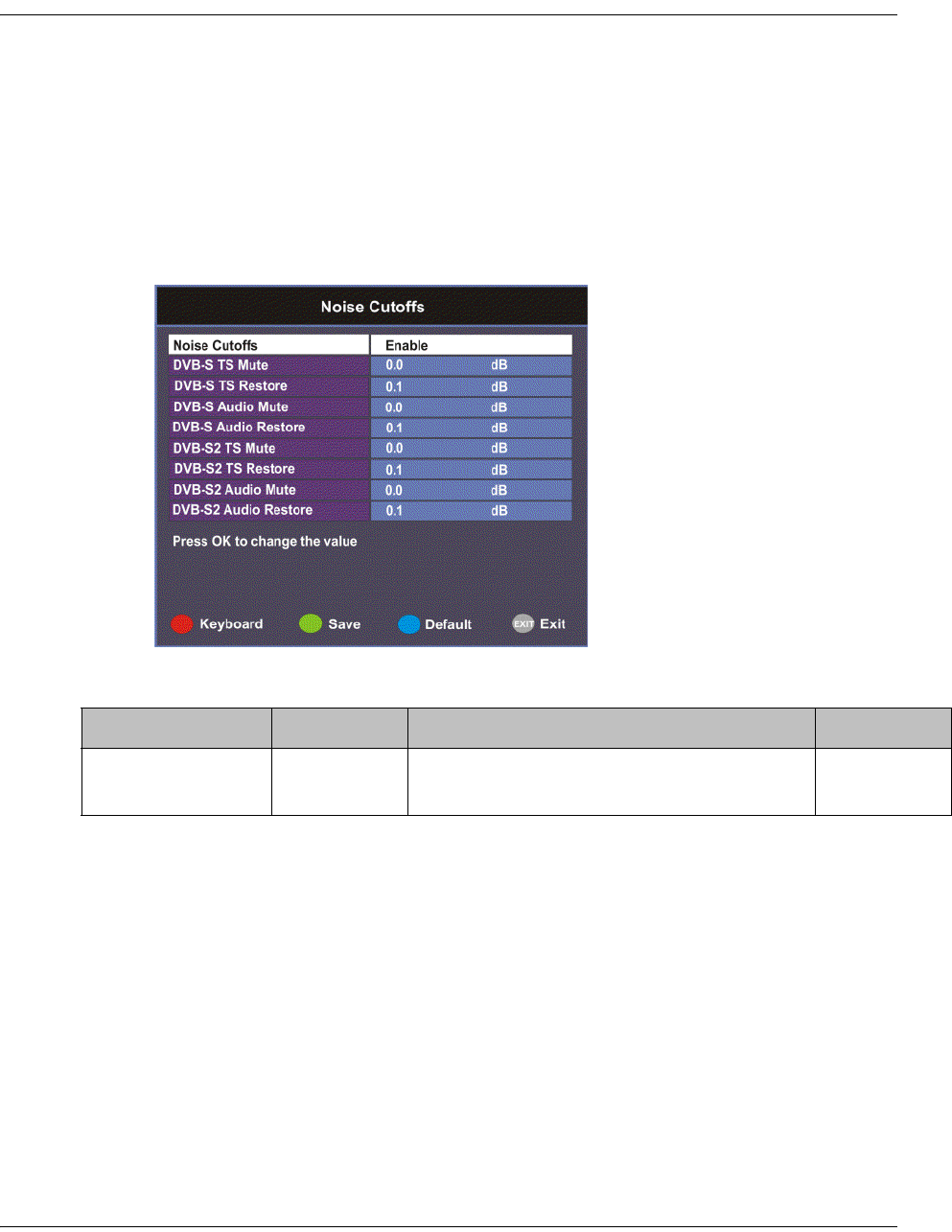
4035197 Rev C D9865 Satellite Receiver Installation and Operation Guide 4-63
Configuring Noise Cutoffs
Setting the Noise Cutoff parameters
The Noise Cutoffs screen allows you to set the muting thresholds for both audio
and video in the event of a noisy signal.
Proceed as follows to configure the noise cutoffs:
1. From the Advanced Setup screen, select Noise Cutoffs and press OK. A
message appears confirming that you want to edit the noise cutoffs.
2. Select Yes to edit. Otherwise, select No.
3. The following table describes each of the options:
Selection Options Description Default
Noise Cutoffs Enable or
Disable
Sets whether to enable or disable the noise
cutoffs functionality.
Enable

4-64 D9865 Satellite Receiver Installation and Operation Guide 4035197 Rev C
DVB-S/DVB-S2 TS
Mute
-5.0 to 20.0
dB
This sets how the receiver reacts when the
signal quality is severely degraded when
using DVB-S or DVB-S2 modulation. This
allows you to set the transport C/N
margin values for the receiver. The
receiver uses these noise values/settings
as limits during normal operation to
determine whether to mute the transport
in the event of a noisy signal, poor signal
or no signal condition.
The mute is the lower limit for the
transport C/N margin setting. The
transport will be muted when the C/N
margin is below the cutoff setting for a
nominal delay of 1 second. The delay is
between the time the condition is first
detected and the time the transport is
muted.
0.0
DVB-S/DVB-S2 TS
Restore
-5.0 to 20.0
dB
This sets how the receiver reacts when the
signal quality is severely degraded when
using DVB-S or DVB-S2 modulation. This
allows you to set the transport C/N
margin values for the receiver. The
receiver uses these noise values/settings
as limits during normal operation to
determine whether to mute the transport
in the event of a noisy signal, poor signal
or no signal condition.
This is the upper limit for the transport C/
N margin setting. The transport will be
un-muted (e.g., restored) when the C/N
margin rises above the Restore setting for
a nominal delay of 8 seconds. The delay is
between the time the condition is first
detected and the time the transport is
restored.
0.1
Selection Options Description Default
4035197 Rev C D9865 Satellite Receiver Installation and Operation Guide 4-65
The following displays the transport and audio default C/N Margin relationships:
Transport Default C/N Margin Relationship
DVB-S/DVB-S2
Audio Mute
-5.0 to 20.0
dB
This is used to set the Audio channel
Cutoff and Restore C/N margin values
(limits) to mute audio when the signal
quality is severely degraded when using
DVB-S or DVB-S2 modulation.
The Cut Off is the lower limit for the audio
C/N margin setting. Audio will be muted
when the C/N margin is below the Cutoff
setting for a nominal delay of 4 seconds.
The delay is between the time the
condition is first detected and the time the
transport is muted.
0.0
DVB-S/DVB-S2
Audio Restore
-5.0 to 20.0
dB
This is used to set the Audio channel
Cutoff and Restore C/N margin values
(limits) to mute audio when the signal
quality is severely degraded when using
DVB-S or DVB-S2 modulation.
The Restore is the upper limit for the
audio C/N margin setting. Audio will be
un-muted (e.g., restored) when the C/N
margin rises above the Restore setting for
a nominal delay of 8 seconds. The delay is
between the time the condition is first
detected and the time the transport is
restored.
0.1
Selection Options Description Default
Transport Mute
Transport Restore
0.1
0.0 Transport Muted
Transport Restored
Transport
C/N Margin

4-66 D9865 Satellite Receiver Installation and Operation Guide 4035197 Rev C
Configuring Noise Cutoffs, Continued
Audio Default C/N Margin Relationship
4. If you want to restore the transport stream and audio C/N margin options to
their factory set (default) values, press the blue button (Default). A message
appears confirming to restore to default values. Press OK to confirm.
5. Press the green button (Save) to save and apply the settings to the receiver.
Audio Mute
Audio Restore
0.1
0.0 Audio Muted
Audio Restored
Audio
C/N Margin
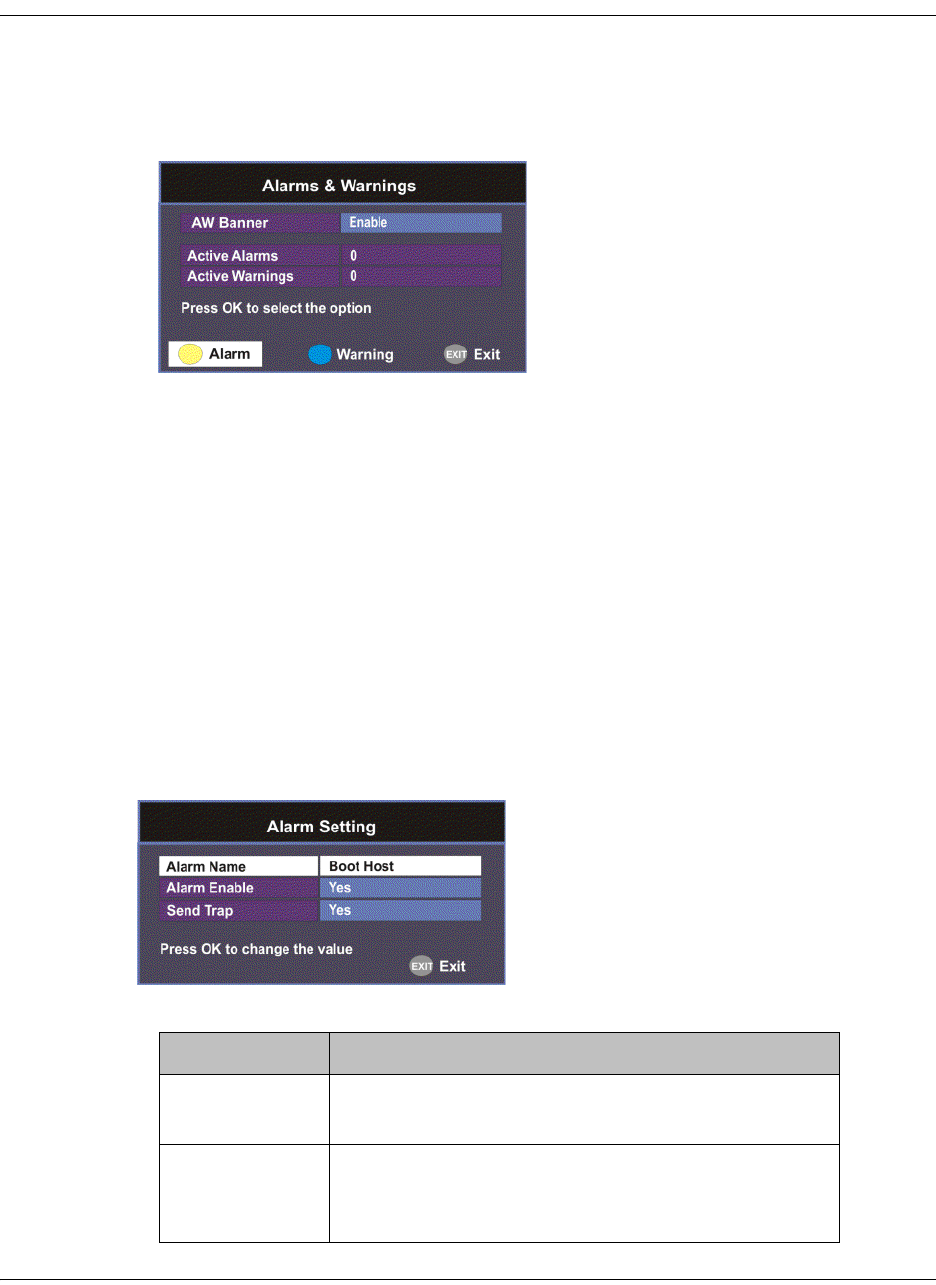
4035197 Rev C D9865 Satellite Receiver Installation and Operation Guide 4-67
Setting up Alarms and Warnings
To Set Up Alarms and Warnings
Proceed as follows to set up the alarms and warnings:
1. From the Advanced Setup screen, select Alarms & Warnings and press OK.
2. Set whether alarms and warnings are to be displayed on-screen in AW Banner
(Enable or Disable).
Note: The alarms and warnings will only appear on-screen if the screen is
displaying video only. The AW Banner will not appear if EPG, Channel Banner
or on-screen menus are displayed.
3. The Active Alarms displays the number of currently active Alarms, and the
Active Warnings indicates the number of currently active Warnings.
4. Press the yellow button (Alarm) to configure the alarm settings. Press the blue
button (Warning) to configure the warning settings.
To configure the Alarm settings
1. From the Alarms & Warnings screen, press the yellow button (Alarm) on the
remote control.
2. Set the following alarm options:
Alarm Setting Description
Alarm Name Displays a list of the alarm/fault messages. You
can scroll through the list using the buttons.
Alarm Enable When set to Yes, the alarm message will be
reported. When set to No, the fault will not be
reported.
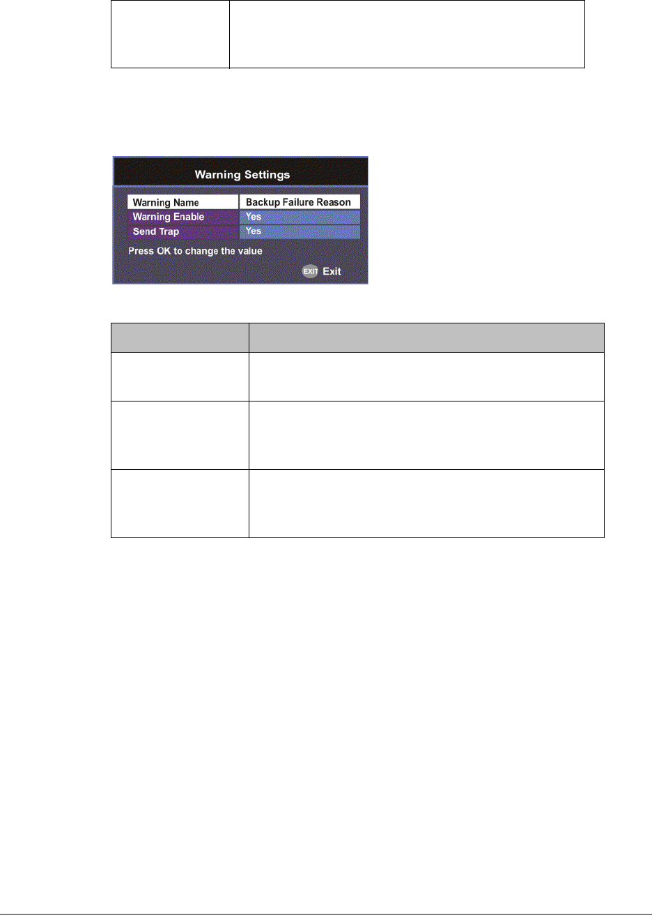
4-68 D9865 Satellite Receiver Installation and Operation Guide 4035197 Rev C
To configure the Warning settings
1. From the Alarms & Warnings screen, press the blue button (Warning) on the
remote control.
2. Set the following warning options:
Send Trap
(D9865D only)
When set to Yes, the SNMP trap message will be
sent to the trap destination; otherwise the fault
message will be ignored.
Warning Setting Description
Warning Name Displays a list of the warning messages. You can
scroll through the list using the buttons.
Warning Enable When set to Yes, the warning message will be
reported. When set to No, the fault won’t be
reported.
Send Trap
(D9865D only)
When set to Yes, the SNMP trap message will be
sent to the trap destination; otherwise the warning
message will be ignored.
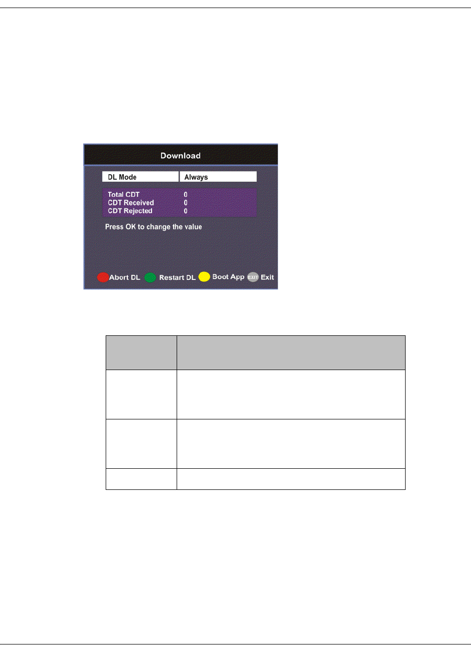
4035197 Rev C D9865 Satellite Receiver Installation and Operation Guide 4-69
Viewing Downloads
Performing Over-the-Air Downloads
Over-the-air downloads are controlled by the uplink. This feature is set to Always
so that the uplink performs downloads to the receiver when necessary. Use this
feature if you want to control over-the-air downloads at the receiver, restart a
download due to signal interruption, or abort the operation at any time.
To restart an over-the-air download:
1. From the Advanced Setup screen, select Download and press OK.
2. Select the DL Mode. The options are Always, Once, or Never. This feature is set
to Always for normal operation.
3. Press the green button (Restart DL) to start an over-the-air download. You can
press the red button (Abort DL) at any time to abort the download operation.
4. Once the download is complete, the receiver reboots. Following reboot, the
receiver returns to the last viewed channels.
DL Mode
Setting
Description
Always Normal (default) setting for everyday
operation. Downloads are performed as
necessary by the uplink.
Once Use this setting if you want to perform an
instantaneous download. The state changes
to Never once the download is complete.
Never Use only when downloads are not required.
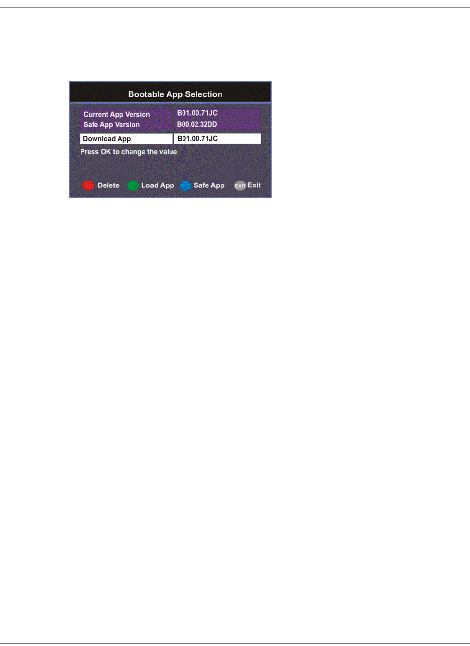
4-70 D9865 Satellite Receiver Installation and Operation Guide 4035197 Rev C
Setting Bootable Application Selection
To View Application Version numbers
Proceed as follows to view the application version numbers:
From the Download screen, press the yellow button (Boot App).
The Current App Version displays the currently running loaded application
version number. The Safe App Version displays the factory loaded application
version number.
To Change the Download Application
The Download App field allows you to select a different application version
application to load to your receiver. Press the green button (Load App) to load the
selected application version and reboot the receiver.
Press the blue button (Safe App) to reboot the receiver and load the factory
installed application version.
Press the red button (Delete) to remove the selected application version. You will
be prompted to continue or not. Press OK to continue the deletion.
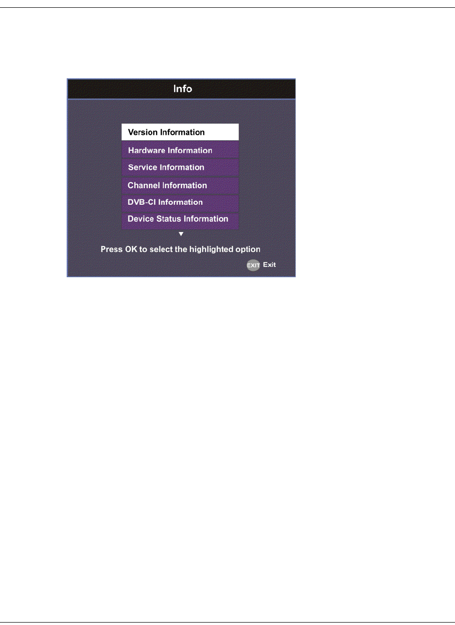
4035197 Rev C D9865 Satellite Receiver Installation and Operation Guide 4-71
System Information
To View the System Information
Proceed as follows to view the System Information screen.
From the Setup Menu screen, select Info and press OK.
The function for the available sub-menus is as follows:
•Version
This menu displays the current and factory loaded application version numbers.
•Hardware
From this menu, it provides the D9865 receiver’s hardware information.
•Service
This menu displays the channel service information.
• Channel
This menu displays the current channel information.
•DVB-CI
This menu displays the CAM (Conditional Access Module) Smart Card
information for the CI (Common Interface) slot.
• Device Status
This menu displays the status of the D9865 receiver.
•Active Alarm
This menu lists all the active alarm messages.
• Active Warning
This menu lists all the active warning messages.
•RF Status
From this menu, it displays the RF input status.
•ADP Status
This menu displays the Encrypted and Non-encrypted Addressed Data Packet
Count information.

4-72 D9865 Satellite Receiver Installation and Operation Guide 4035197 Rev C
Viewing the Version Information
To View the Version Information
Proceed as follows to view the version information.
From the Info screen, select Version Information and press OK.
The following table displays the version information:
Version Information Description
Curr Ver Indicates the currently running loaded application
version number.
Safe Ver Indicates the factory loaded application version
number.
Boot Ver Indicates the receiver Boot application version
number.
PIC Ver Indicates the Programmable Interrupt Controller
(PIC) version number.
Tuner Ver Indicates the version number of the tuner.
ISE Ver, ISE UA Displays the ISE Version Number and ISE User
Address.
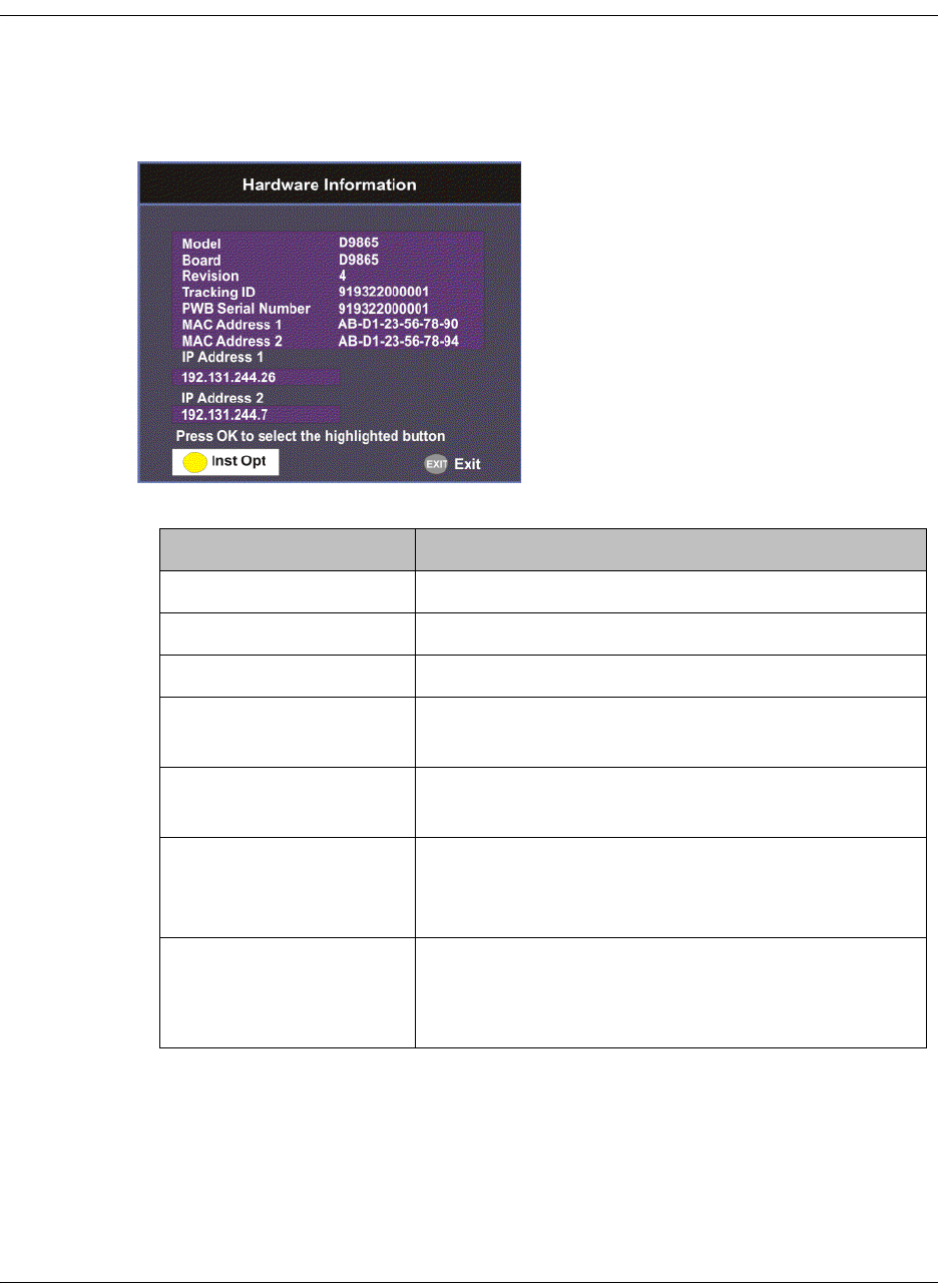
4035197 Rev C D9865 Satellite Receiver Installation and Operation Guide 4-73
Viewing Hardware Information
To View the Hardware Information
Proceed as follows to view the hardware information.
From the Info screen, select Hardware Information and press OK.
The following table displays the hardware information:
Hardware Information Description
Model Indicates the model number of the receiver.
Board Indicates the board type.
Revision Indicates the board revision number.
Tracking ID This is the unique Tracking ID number that
identifies the product version.
PWB Serial Number Displays the serial number for the PWB (printed
wiring board).
MAC Address 1,
MAC Address 2
(D9865D only)
Indicates the MAC addresses assigned to the
Ethernet interface at the time of manufacture.
IP Address 1 and IP
Address 2 (D9865D
only)
Indicates the IP address assigned to the receiver in
a network for Port 1 and Port 2.
Note: Only Port 1 is available for this release.
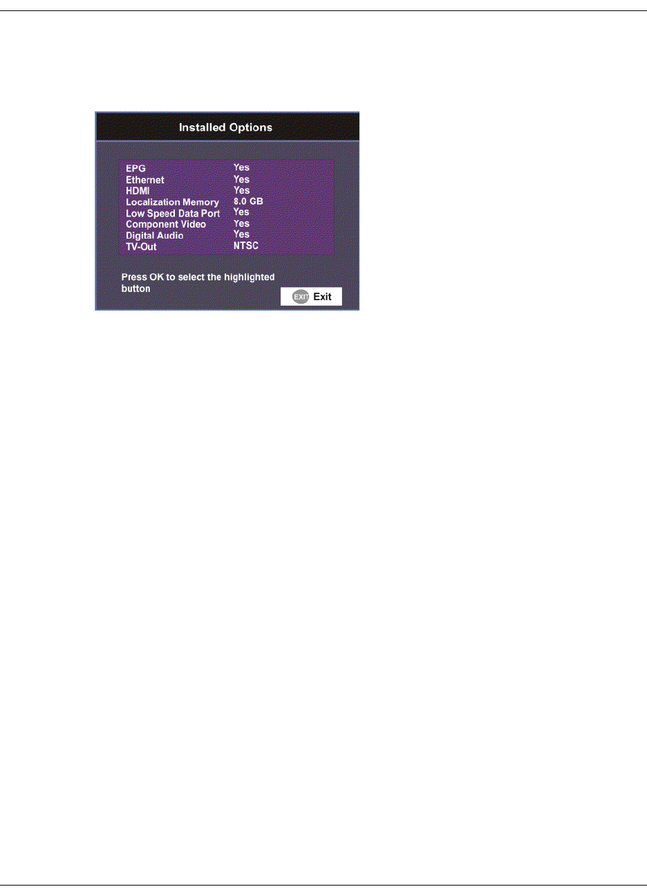
4-74 D9865 Satellite Receiver Installation and Operation Guide 4035197 Rev C
Viewing Installed Options
To view the Installed Options
Proceed as follows to view the installed hardware options:
From the Hardware Information screen, press the yellow button (Inst Opt).
The Installed Options screen displays the hardware options installed in the current
D9865 satellite receiver.
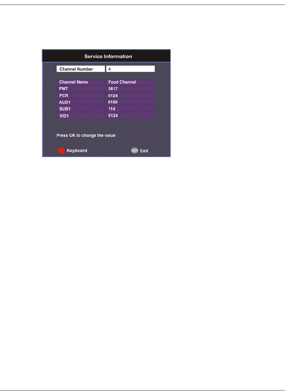
4035197 Rev C D9865 Satellite Receiver Installation and Operation Guide 4-75
Viewing Service Information
To View the Service Information
Proceed as follows to view the service information.
From the Info screen, select Service Information and press OK.
The Service Information screen displays the PIDs associated with a selected
channel.
About Subscriber Services
Subscriber uplink services made available to your satellite receiver are associated
with virtual channels. These channels can include video, audio, and/or data
services. All authorized virtual channel services are provided via PowerVu
Network Centre (PNC) system software and broadcast facility equipment, and are
decoded by the receiver. You can view available subscriber services for any
received virtual received channel on this menu and tune to the selected channel by
entering the particular Channel Number.
About the Current Channel
When you navigate to menus from video, the information displayed is associated
with the current (video) channel. If no changes have been made to the current setup,
you can automatically return to the same channel when you exit to video.
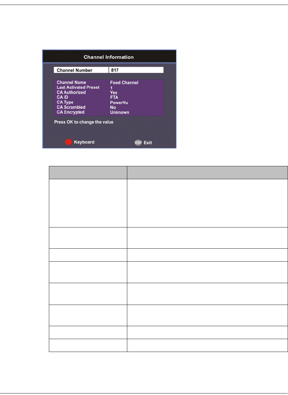
4-76 D9865 Satellite Receiver Installation and Operation Guide 4035197 Rev C
Viewing Channel Information
To View the Channel Information
Proceed as follows to view the Channel Information screen:
From the Info screen, select Channel Information and press OK.
The Channel Information screen displays the following information:
Channel Information Description
Channel Number Current channel number.
To change the current channel number, press OK.
Enter the number using the keypad on the remote
control and click OK. It tunes to the selected
channel.
Channel Name Current channel name associated with the channel
number.
Last Activated Preset Indicates the number of the last activated preset.
CA Authorized Indicates whether the receiver is authorized to
receive the signal.
CA Id Indicates the identification number of the CA used
for the received signal.
CA Type Indicates the type of CA used for the received
signal.
CA Scrambled Indicates whether the received signal is scrambled.
CA Encrypted Indicates whether the received signal is encrypted.
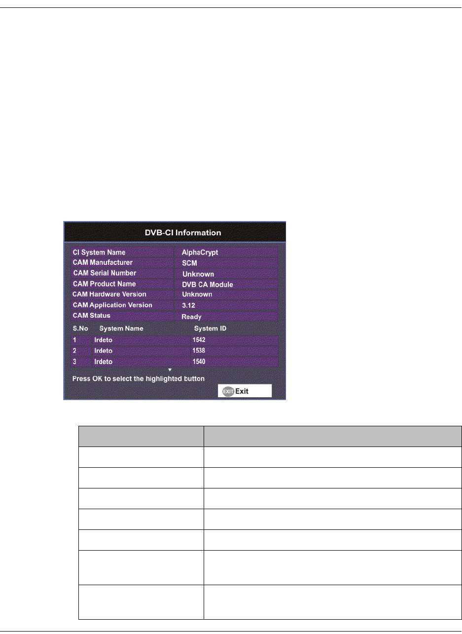
4035197 Rev C D9865 Satellite Receiver Installation and Operation Guide 4-77
Viewing DVB-CI Information
The Common Interface (CI) slot is located behind the door on the front panel. They
allow use of a CAM (Conditional Access Module) Smartcard to decrypt purchased
programming.
Note: You must be authorized to view the programming available via the Smart
Card from your service provider.
Note: CAMs must be purchased from Cisco. For a list of the supported CAMs, see
Common Interface Modules, on page 3-5.
For more information on configuring the CI information, see Configuring the
Common Interface (CI) Information, on page 5-28.
To View the Current DVB-CI Information
Proceed as follows to view the DVB-CI information:
From the Info screen, select DVB-CI and press OK.
The DVB-CI Information screen displays the following information:
DVB-CI Information Description
CI System Name Indicates the system name of the CAM.
CAM Manufacturer Displays the manufacturer name of the CAM.
CAM Serial Number Indicates the unique serial number of the CAM.
CAM Product Name Displays the product name of the CAM.
CAM Hardware Version Displays the hardware version number of the CAM.
CAM Application
Version
Displays the software version number of the CAM.
CAM Status Displays the status of the CAM (Ready or Not
Ready).

4-78 D9865 Satellite Receiver Installation and Operation Guide 4035197 Rev C
S.No/System Name/
System ID
Displays the CA system identification number and
name of the CAM. Some CAMs may support
multiple CA system IDs.
DVB-CI Information Description
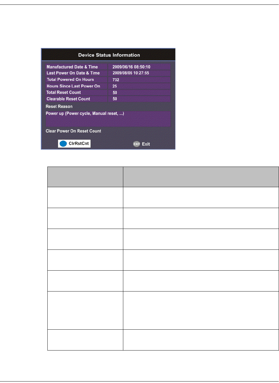
4035197 Rev C D9865 Satellite Receiver Installation and Operation Guide 4-79
Viewing Device Status Information
To View the Device Status Information
Proceed as follows to view the device status information:
From the Info screen, select Device Status and press OK.
The Device Status Information screen displays the following information:
Device Status
Information
Description
Manufactured Date &
Time
Displays the date and time when the receiver was
manufactured.
Last Power On Date &
Time
Displays the date and time when the receiver was
powered up.
Total Powered On
Hours
Displays the total number of hours that the receiver
has been operating.
Hours Since Last Power
On
Displays the number of hours since the last power-
on.
Total Reset Count Displays the total number of times the receiver has
been restarted.
Clearable Reset Count Displays the number of restarts since the last time
the restart count was cleared.
To clear or reset the Clearable Reset Count, press the
blue button (ClrRstCnt).
Reset Reason Displays the reason for the last restart, i.e., power
cycle or manual reset.
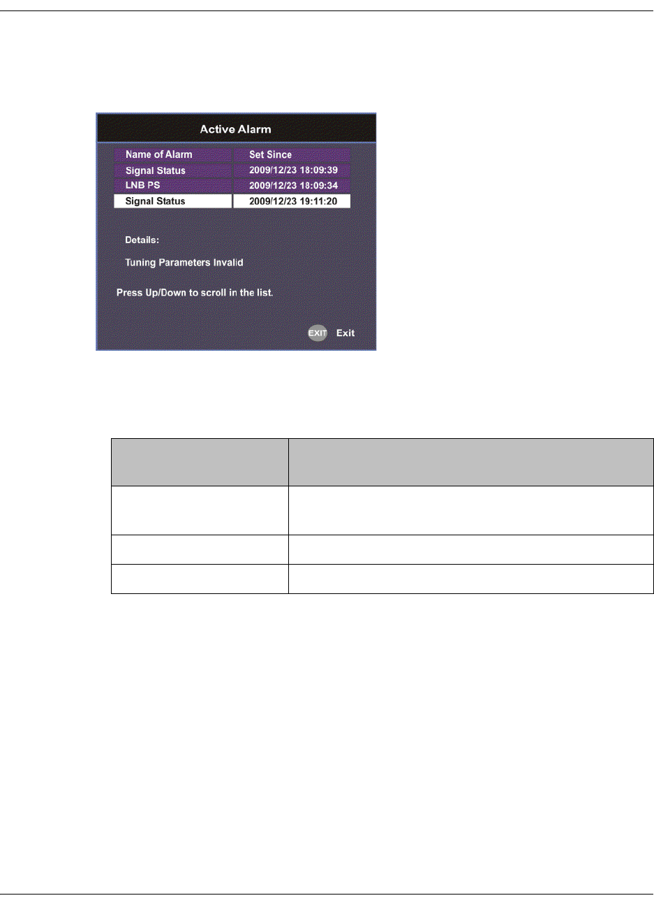
4-80 D9865 Satellite Receiver Installation and Operation Guide 4035197 Rev C
Viewing the Active Alarm and Warning Messages
To View the Active Alarm Messages
Proceed as follows to view the active alarms:
From the Info screen, select Active Alarm and press OK.
The Active Alarm screen displays all the active alarm messages for the D9865
system.
The following table shows the alarm status table information:
Active Alarm
Information
Description
Name of Alarm Name of the alarm. For more information on alarm
messages, refer to Messages, on page 7-2.
Set Since Date and time of the alarm.
Details Displays the content of the message.
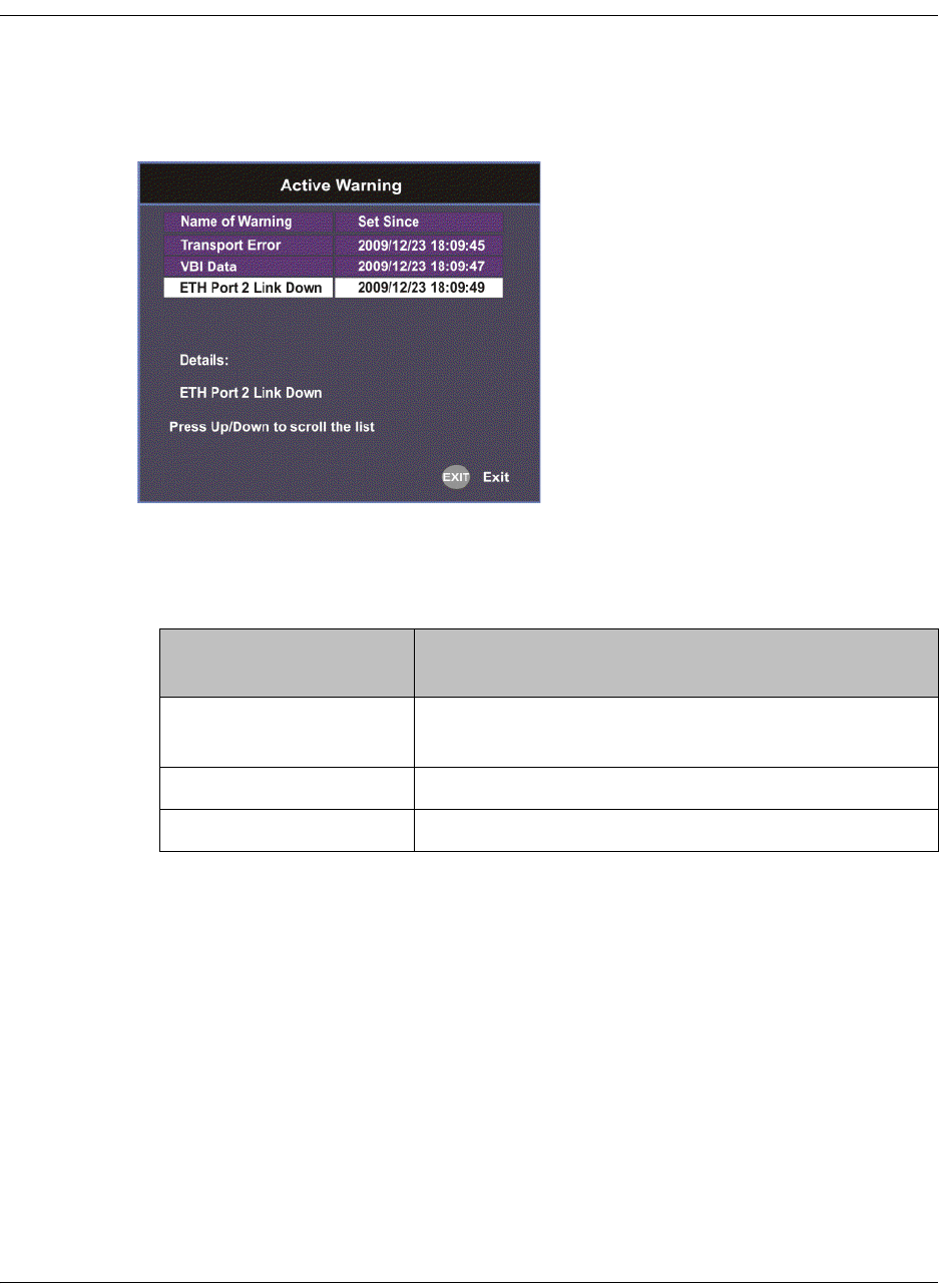
4035197 Rev C D9865 Satellite Receiver Installation and Operation Guide 4-81
Viewing the Active Alarm and Warning Messages, Continued
To View the Active Warning Messages
Proceed as follows to view the active warnings:
From the Info screen, select Active Warning and press OK.
The Active Warning screen displays all the active warning messages for the D9865
system.
The following table shows the warning status table information:
Active Warning
Information
Description
Name of Warning Name of the warning. For more information on
warning messages, refer to Messages, on page 7-2.
Set Since Date and time of the warning.
Details Displays the content of the message.
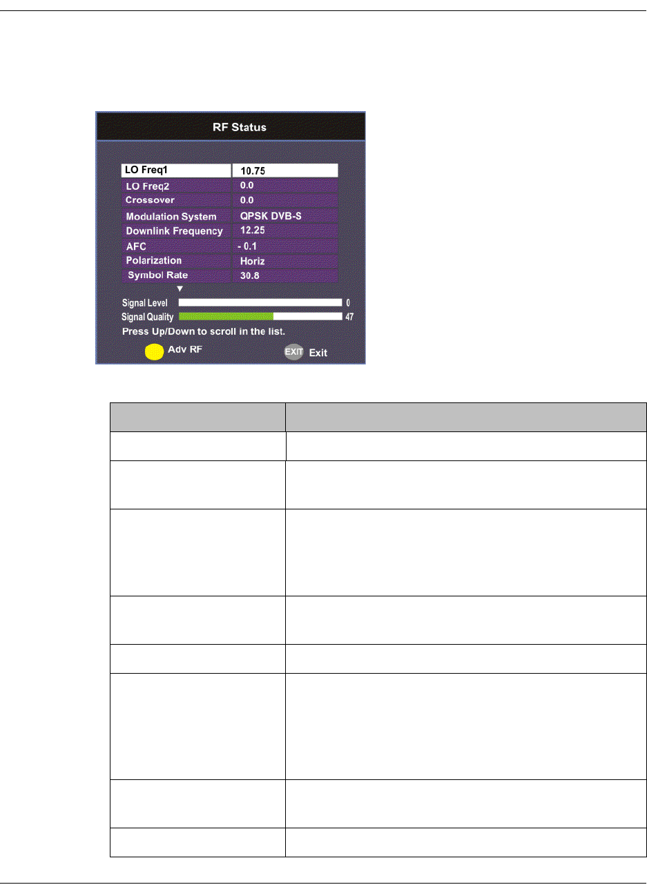
4-82 D9865 Satellite Receiver Installation and Operation Guide 4035197 Rev C
Viewing the RF Status
To View the RF Status Information
Proceed as follows to view the RF status:
From the Info screen, select RF Status and press OK.
The following table describes the RF Status information displayed:
RF Status Description
Downlink Frequency Indicates the current downlink frequency, in GHz.
Symbol Rate Indicates the Symbol Rate of the received signal, in
MS/s.
Polarization Indicates the signal polarization setting. This setting
is only applicable when LNB Power is set to H-NIT
or V-NIT. The selected setting must match the
polarization of the transmitted signal.
FEC Indicates the FEC (Forward Error Correction) rate of
the received signal.
LO Freq 1/2 Displays the Local Oscillator frequency #1 and #2.
Crossover Indicates the crossover frequency, which is an
internal threshold frequency used for selecting the
LO1 or LO2 frequency, depending on the current
Downlink frequency setting. This is only used in
Ku-Band dual LNB application.
AFC Indicates the current Automatic Frequency Control
adjustment, in MHz.
Modulation System Indicates the modulation type of the received signal.
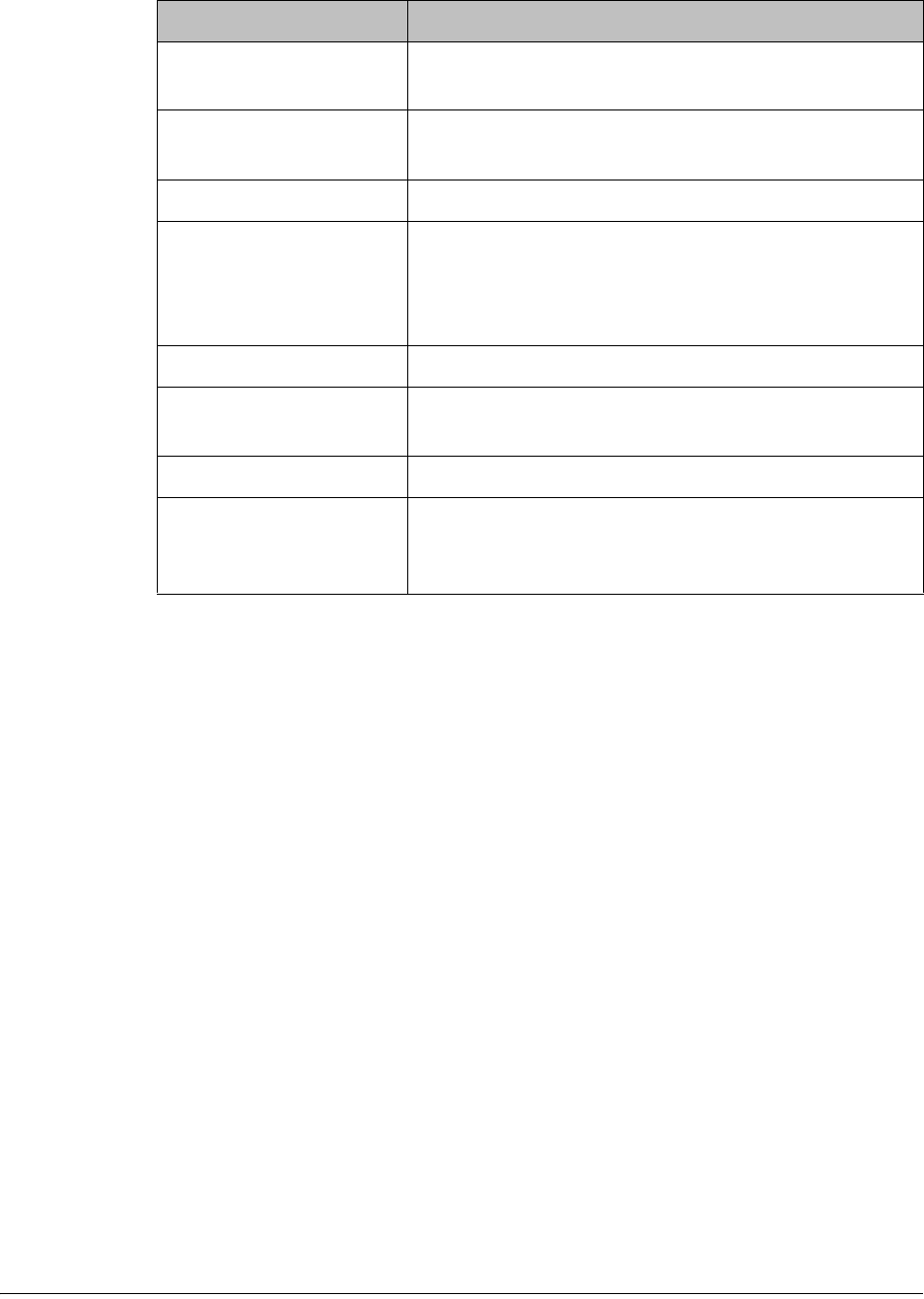
4035197 Rev C D9865 Satellite Receiver Installation and Operation Guide 4-83
Signal Level and Signal Quality
The Signal Level and Signal Quality of the incoming signal are displayed both
numerically and graphically using bar graphs.
The Signal Level is associated with the RF input signal level. The Signal Level
display is continuously updated to indicate the relative strength of the received RF
input signal. It is displayed in the range from 0 to 100.
The Signal Quality is associated with the Bit Error Rate (displayed in the range from
0 to 100). The Signal Quality is continuously updated to indicate the relative quality
of the received RF input signal.
PV BER Indicates the PV (Post-Viterbi) BER of the received
signal (DVB-S only).
LDPC BER Indicates the LDPC (Low-Density Parity-Check)
error rate of the selected input (DVB-S2 only).
PER Indicates the current PER (Packet Error Rate).
C/N Margin Indicates the current Carrier-to-Noise Margin of the
received signal, in dB. The Carrier-to-Noise margin
is the actual distance that C/N is from the noise
threshold.
Signal Lock Indicates the current signal lock status for the input.
Rolloff Mode Indicates the rolloff mode of the incoming signal.
The default is set to Auto.
Rolloff Factor Indicates the rolloff factor of the incoming signal.
LNB PS Status Indicates the current LNB connection status (No
Load, Overloaded, OverTemp, Short Circuit,
Disabled, Normal, or N/A).
RF Status Description
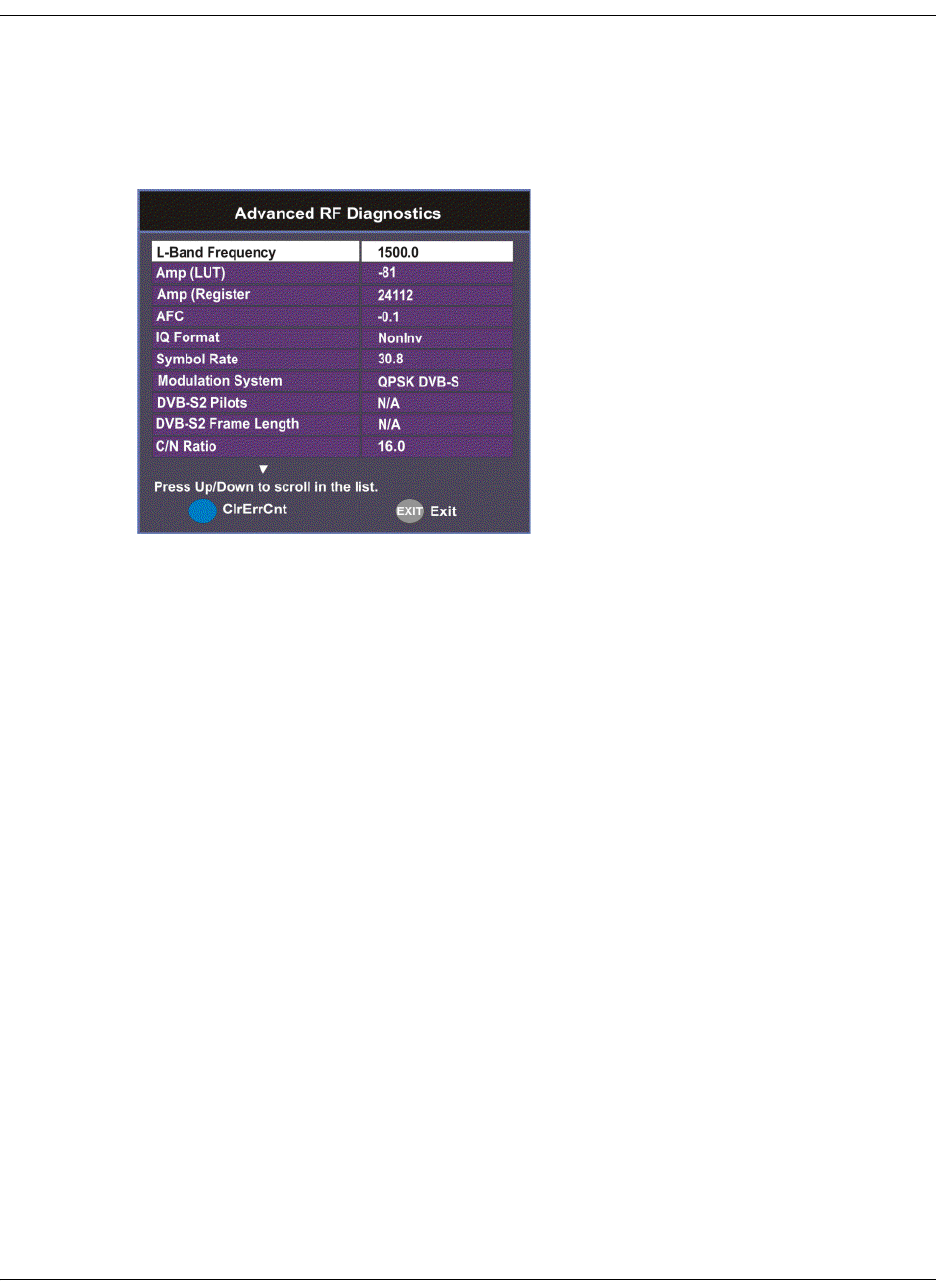
4-84 D9865 Satellite Receiver Installation and Operation Guide 4035197 Rev C
Viewing Advanced RF Diagnostics
The Advanced RF diagnostics screen is primarily used by Cisco customer support
for information purposes only, if needed.
Proceed as follows to view the Advanced RF Diagnostics screen:
From the RF Status screen, press the blue button (Adv RF).
Press the blue button (ClrErrCnt) to clear the error counters.
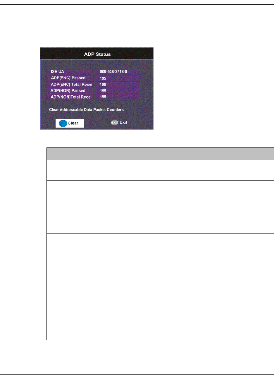
4035197 Rev C D9865 Satellite Receiver Installation and Operation Guide 4-85
Viewing ADP Status
To View the ADP Status
Proceed as follows to view the ADP Status screen.
From the Info screen, select ADP Status and press OK.
The following table describes the ADP status information displayed:
ADP Status Description
ISE UA Indicates the ISE User Address (14 hexadecimal
characters).
ADP(ENC) Passed Indicates the current Encrypted Addressed Data
Packet Count. This count indicates the amount of
transmitted ADP information being accurately
received and processed. Ideally, the ADP(ENC)
Passed and ADP(ENC) Total Received numbers
should be identical.
ADP(ENC) Total
Received
Indicates the total Encrypted Addressed Data
Packet Count. This count indicates the amount of
transmitted ADP information being accurately
received and processed. Ideally, the ADP(ENC)
Passed and ADP(ENC) Total Received numbers
should be identical.
ADP(NON) Passed Indicates the current Non-Encrypted Addressed
Data Packet count. This count indicates the amount
of transmitted ADP information being accurately
received and processed. Ideally, the ADP(NON)
Passed and ADP(NON) Total Received numbers
should be identical.

4-86 D9865 Satellite Receiver Installation and Operation Guide 4035197 Rev C
Press the blue button (Clear) to clear the total numbers above. To help the operator
make accurate analysis of the receiver’s functionality, the ADP(ENC) and
ADP(NON) numbers should be cleared. These same values are also reset whenever
the receiver is turned on, reset, or power-cycled.
ADP(NON) Total
Received
Indicates the total Non-Encrypted Addressed Data
Packet count. This count indicates the amount of
transmitted ADP information being accurately
received and processed. Ideally, the ADP(NON)
Passed and ADP(NON) Total Received numbers
should be identical.
ADP Status Description

4035197 Rev C D9865 Satellite Receiver Installation and Operation Guide 5-1
Chapter 5
Setup and Monitoring via Web GUI
Overview
In This Chapter
This chapter contains the following topics.
Topic See Page
Logging on to the Web GUI 5-3
Web GUI - Summary Screen 5-4
Links 5-6
D9865 Web GUI Environment 5-7
Tuning Setup 5-9
Setting Up Dish Pointing 5-12
Setting up SI Receive Parameters 5-16
Setting up Muting Threshold Controls 5-18
Setting up the Tuning Presets/LNB 5-21
Setting up LNB Presets 5-23
Viewing Input Status 5-25
Setting the Channel Information 5-26
Configuring the Common Interface (CI) Information 5-28
Viewing the PSI Tables 5-32
Viewing PSI Frequency Information 5-33
Viewing the PSI Channels 5-34
Setting up the Video 5-35
Configuring Captions 5-37
Setting up Subtitles 5-38
Setting up Audio 5-41
Viewing System Information 5-43
Viewing Features/Licenses 5-44
Setting Up IP Information 5-45
5-2 D9865 Satellite Receiver Installation and Operation Guide 4035197 Rev C
Setting Up IP Routing 5-46
Setting Up SNMP and Trap Destinations 5-48
Configuring Time/Clock Information 5-50
Configuring Favorites and Reminders 5-51
Viewing the Alarm/Warning Status 5-53
Setting Up Alarms and Warnings 5-54
Viewing the Alarm/Warning History 5-56
Viewing Version Information 5-57
Setting Up Import/Export Information 5-59
Viewing the Backup/Restore History 5-61
Managing D9865 Web GUI Accounts 5-62
Configuring Lock Level Settings 5-65
Viewing Contact Information 5-67
Viewing Diagnostic Logs 5-68
Viewing the Usage Counters 5-69
Performing Service Actions 5-71
Topic See Page
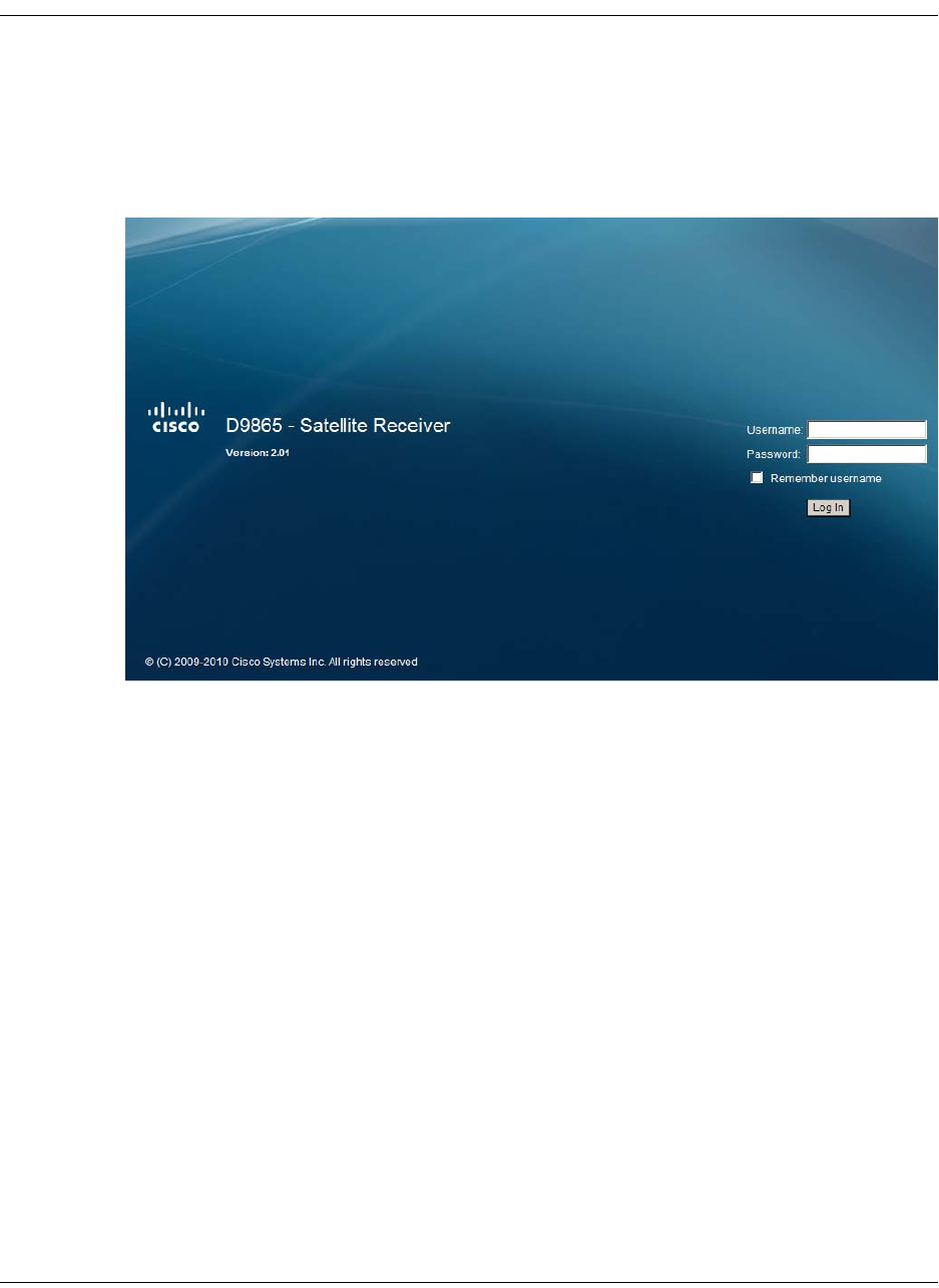
4035197 Rev C D9865 Satellite Receiver Installation and Operation Guide 5-3
Logging on to the Web GUI
To Log on to the Web GUI
Proceed as follows to log on to the Web GUI:
1. Open MS Internet Explorer.
2. Type the IP address of the D9865 Satellite Receiver in the address bar and press
Enter.
3. Type the Username and Password.
Note: The username and password are case-sensitive. The default username is
admin and the default password is localadmin. If you have forgotten your
username and password, you can reset them to its factory defaults from the on-
screen menu of the D9865 Satellite Receiver. For more information, refer to
System Information, on page 4-71.
Important: The password and user name will be remembered for the whole
web session. Close the web browser if you want to prevent others from
accessing the settings of the D9865 Satellite Receiver.
If your session expires, you must refresh the browser and log back in.
4. Click Log In.
Note: If you select Remember username, the user name will be remembered
the next time you log into the web GUI.
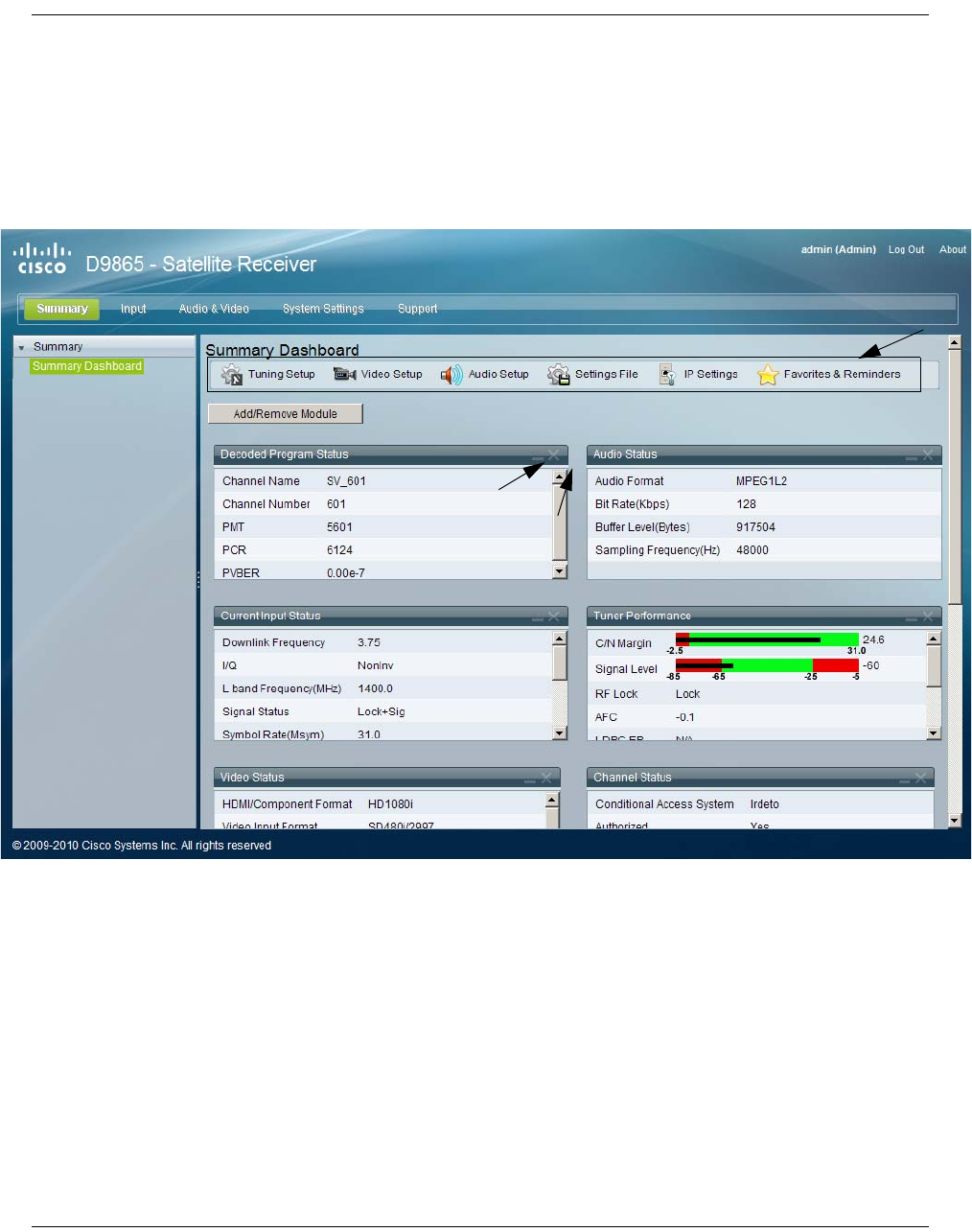
5-4 D9865 Satellite Receiver Installation and Operation Guide 4035197 Rev C
Web GUI - Summary Screen
To get an Overview of the Main D9865 Settings
Proceed as follows to get an overview of the main D9865 Satellite Receiver settings:
1. Log on to the Web GUI.
2. Click Summary > Summary Dashboard. The Summary Dashboard page is
displayed.
The summary screen displays the main settings of the D9865 Satellite Receiver.
The buttons above the sections in the Summary Dashboard are shortcuts to the
various setup pages. For example, click Tuning Setup to open the Tuning Setup
page.
You can customize the Summary Dashboard by temporarily minimizing or
removing the modules displayed. Each module has a maximize and minimize
button, allowing you to view or hide various modules. The default view is
displayed when you refresh the Summary Dashboard page.
Buttons - click to open the
specific setup pages.
Minimize/
Maximize
Section Close Section

4035197 Rev C D9865 Satellite Receiver Installation and Operation Guide 5-5
Web GUI - Summary Screen, Continued
You can also customize the Dashboard by clicking on Add/Remove Module. The
Dashboard Configuration window is displayed.
The following table describes the all the available modules:
Module Description
Decoded Program
Status
Displays channel and service information.
Audio Status Displays the current audio status information, such as
the audio format and sampling frequency.
Current Input
Status
Displays the current RF Tuning Status information,
including the downlink frequency and signal status.
Tuner
Performance
Displays the satellite dish status, such as the C/N Margin
and Signal Level.
Video Status Displays the current video information.
Channel Status Displays the channel status information, such as the type
of CA used and whether the receiver is authorized to
receive the signal.
PID Information Displays the PIDs associated with the channels.
CI Status Displays the CAM card information.
Fault Active List Displays the currently active alarms and warnings.

5-6 D9865 Satellite Receiver Installation and Operation Guide 4035197 Rev C
Links
Linked Pages
The GUI of the D9865 has a number of linked pages.
The function for the linked pages is as follows:
• Summary
From this page you can obtain an overview of the D9865 operation.
•Input
From this page you can:
- set presets and LNB,
- configure dish pointing/alignment,
- view input status,
-configure channels,
- configure CI (Common Interface) settings,
- view PSI, Frequency, and Channel tables.
• Audio & Video
From this page you can:
- configure video settings,
- set up closed caption and subtitles,
- configure audio settings,
- view current audio status.
• System Settings
From this page you can:
- view alarm and warning status information
- configure ethernet ports,
- configure lock levels.
• Support
From this page you can:
- view logs,
- view contact information
- View and upgrade software version.
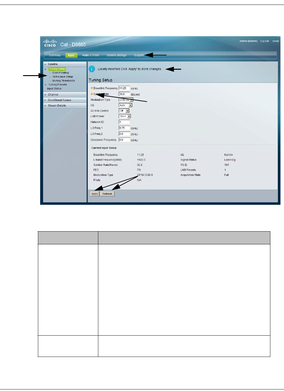
4035197 Rev C D9865 Satellite Receiver Installation and Operation Guide 5-7
D9865 Web GUI Environment
Web GUI Environment
The following is an example of a D9865 Web GUI page.
The Window Buttons
The GUI of the D9865 has the following general buttons:
Indicates a mandatory field.
Icons
Buttons
Links
Displays as you edit the page. Chang-
es are applied on the receiver only
(not on the uplink).
Click Apply to save the changes.
Button Description
Apply Saves and applies the settings to the receiver.
Note: If you make changes on a web page, ensure that
you apply the changes before moving to another page. If
you move to another page without saving your (edits)
changes, the web GUI will revert to the previously saved
settings, and the changes will be lost.
Also, ensure that you save all changes on a web page
before leaving your PC; otherwise, the GUI will
eventually time out and revert back to the previously
saved settings.
Refresh Reads existing data from the D9865. If edits were made in
a setup page, then unsaved changes are discarded.
5-8 D9865 Satellite Receiver Installation and Operation Guide 4035197 Rev C
D9865 Web GUI Environment, Continued
The About Window
The top right hand corner of the D9865 web GUI has an About link. Click to open
the About window.
The About window displays the current D9865 system version information and the
copyright information.
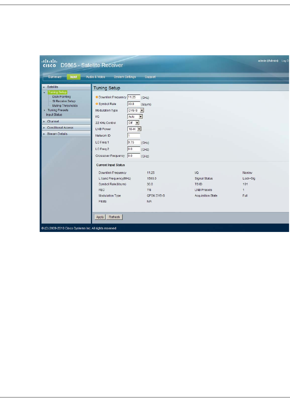
4035197 Rev C D9865 Satellite Receiver Installation and Operation Guide 5-9
Tuning Setup
To Set up Tuning Information
Proceed as follows to configure the Tuning Setup page:
1. From the user interface of the D9865, click Input > Satellite > Tuning Setup.
The Tuning Setup page is displayed.
2. Set the Downlink Frequency used by the receiver for tuning the received digital
signal. You can enter a value in the range from 0.0 to 15.0 GHz. The formula for
C-Band is: Downlink Freq = LO Freq - L-Band Freq. The formula for Ku-Band is
Downlink Freq = LO Freq + L-Band Freq.
3. Type the Symbol Rate. The symbol rate must match that of transmitted signal.
You can enter a value in the range from 1.0 to 45.0 MS/s for DVB-S or 1.0 to 31.0
MS/s for DVB-S2.
4. Select the Modulation Type for the received signal (DVB-S or DVB-S2).

5-10 D9865 Satellite Receiver Installation and Operation Guide 4035197 Rev C
Configuring Tuning Setup, Continued
5. Set the input signal spectrum inversion setting (I/Q), which allows the operator
to track and selected inverted or non-inverted digital signals.
When set to Auto, received digital signals are tracked and inverted for correct
selection, as required. When set to Inv (inverted), the received digital signal is
always inverted. Conversely, when set to NonInv (non-inverted), the received
digital signal is never inverted.
6. The 22 KHz Control is only applicable for dual-band LNB applications. It sets
whether or not the 22 KHz tone is available. The selections are On, Off, or Auto
(if downlink frequency is greater/less than the crossover frequency, the 22KHz
tone is automatically set to on/off). The default is Off.
7. The LNB Power setting determines if power is provided via the input to an
external LNB connection.
You can set the LNB Power to Off, 18-H, 13-V, H-NIT, or V-NIT. The default is
18-H. If LNB Power is set to V-NIT or H-NIT, the signal polarization is
automatically read from the NIT. Power will not be applied to the LNB if LNB
Power is set to Off.
Note: LNB power must be on if DiSEqC is required.
For more information, see LNB Power Settings, on page 4-25.
8. Enter the Network ID of the uplink signal the receiver is to receive when using
this preset. You can obtain the network ID from your service provider. The
default is 1.
9. Set the Local Oscillator Frequency #1 (LO Freq 1), which sets the satellite
antenna LNB local oscillator #1 frequency. For C-Band application, set to 5.15
GHz. For Ku-band single LNB, enter LO Freq and set LO Freq 2 and Crossover
Frequency to 0.0. For Ku-band dual LNB, enter LO Freq 1, LO Freq 2 and
Crossover Frequency. The default is 10.75 GHz.
10. Set the Local Oscillator Frequency #2 (LO Freq 2), which sets the satellite
antenna LNB local oscillator #2 frequency. This option is only used in dual-band
LNB applications. LO Freq 2 must be greater than LO Freq 1. The default is 0.0
GHz.
11. Enter the Crossover Frequency. This is an internal threshold frequency used for
selecting the LO1 or LO2 frequency, depending on the current downlink
frequency settings. This option is only used in dual-band LNB applications. The
default is 0.0 GHz.
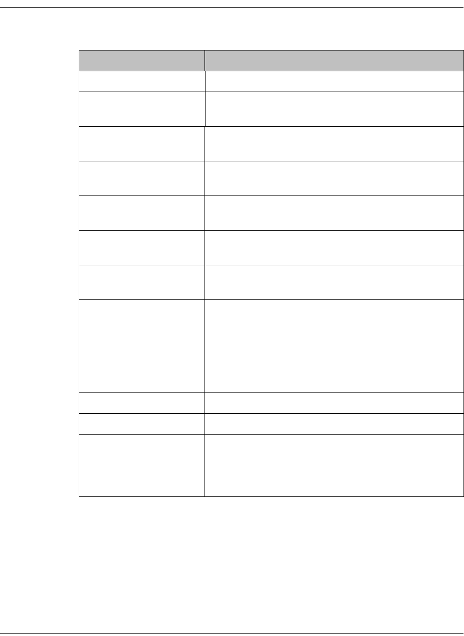
4035197 Rev C D9865 Satellite Receiver Installation and Operation Guide 5-11
Configuring Tuning Setup, Continued
12. The Current Input Status section displays the current RF status. The following
table describes the Current Input Status information displayed:
13. Click Apply.
RF Status Description
Downlink Frequency Indicates the current downlink frequency, in GHz.
L Band Frequency
(MHz)
Indicates the current L-Band frequency, in MHz.
Symbol Rate (Msym) Indicates the Symbol Rate of the received signal, in
MS/s.
FEC Indicates the FEC (Forward Error Correction) rate of
the received signal.
Modulation Type Indicates the modulation type for the received
signal.
Pilots Indicates whether the pilots for the DVB-S2
modulation is on or off.
I/Q Indicates the input signal spectrum inversion
setting.
Signal Status Indicates the current signal lock status for the input.
Locked - Receiver is locked to a carrier with no valid
content.
Lock+Sig - Receiver is locked to a carrier with valid
content.
No Lock - Receiver is not locked to a carrier.
TS ID Displays the Transport Stream ID.
LNB Presets Indicates the number of LNB presets configured.
Acquisition State Displays Full if the ASI and PSI tables have all been
found. Otherwise, it will display Degraded if there
are missing tables or None if no ASI or PSI tables
have been found.
5-12 D9865 Satellite Receiver Installation and Operation Guide 4035197 Rev C
Setting Up Dish Pointing
To Set Up Dish Pointing
The Dish Pointing page allows you to configure the satellite dish position. There are
two modes: User Action (default) or Installer Action. The User Action mode allows
you to select from stored Satellite Numbers, which are stored satellite locations, as
stored in the dish motor, but does not provide any dish control.
Proceed as follows to set up the dish in User Action mode:
1. From the user interface of the D9865 Satellite Receiver, click Input > Satellite,
expand Tuning Setup and then click Dish Pointing. The Dish Pointing page is
displayed.
2. Enter the Satellite Number identifying the saved satellite location, as defined by
the dish motor manufacturer. You can enter a value in the range from 1 to 255.
3. Select Goto Satellite as the User Action to move the dish to the selected pre-
stored satellite position. Satellite positions are stored in the dish motor, if
supported, not in the receiver. Select None if no action is performed.
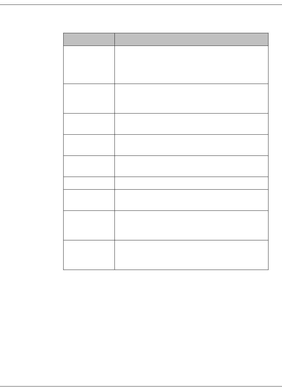
4035197 Rev C D9865 Satellite Receiver Installation and Operation Guide 5-13
Setting Up Dish Pointing, Continued
4. The Dish Status section displays the current satellite dish information. The
following table describes the satellite dish information displayed:
5. Click Apply.
Parameter Description
C/N Margin Indicates the current Carrier-to-Noise Margin for
the received signal. The Carrier-to-Noise margin is
the actual distance that C/N is from the noise
threshold.
Signal Level Displays the relative strength of the received RF
input signal. It is displayed in the range from 0 to
100.
RF Lock Indicates whether the receiver is synchronized with
the received RF signal.
AFC Indicates the current Automatic Frequency Control
adjustment, in MHz.
LDPC ER Indicates the bit rate of the input stream of the
LDPC error correction stage (DVB-S2 only).
Packet ER Indicates the current Packet Error Rate.
PV BER Indicates the PV (Post-Viterbi) BER for the received
signal (DVB-S).
RF(1) Power Displays the LNB Power setting. The LNB Power
setting determines if power is provided via the RF1
Input to an external LNB connection.
LNB Status Indicates the current LNB connection status (No
Load, Overloaded, OverTemp, Short Circuit,
Disabled, Normal, or N/A).
5-14 D9865 Satellite Receiver Installation and Operation Guide 4035197 Rev C
Setting Up Dish Pointing, Continued
Proceed as follows to set up the dish in Installer Action mode:
1. From the Dish Pointing page, click on the Installer Action link at the bottom
right hand corner of the page.
2. Enter the Satellite Number identifying the saved satellite location, as defined by
the dish motor manufacturer. You can enter a value in the range from 1 to 255.
3. Select the Installer Action. The following table describes the actions available:
Options Description
Continuous West
Movement
Moves the dish west until it reaches its limit.
Ensure that the dish can move to its limit
without any obstructions.
Continuous East
Movement
Moves the dish east until it reaches its limit.
Ensure that the dish can move to its limit
without any obstructions.
Stop Move Stops movement of the dish.
Goto Absolute
Position West
Moves the dish to the Absolute west position
set above.
Goto Absolute
Position East
Moves the dish to the Absolute east position
set above.
Goto Reference Moves the dish to a reference defined by the
dish motor manufacturer.
4035197 Rev C D9865 Satellite Receiver Installation and Operation Guide 5-15
4. Enable or disable the Digital Satellite Equipment Satellite Control (DiSEqC).
Note: This must be enabled to control the DiSEqC switch. LNB Power must be
on to use this setting. Refer to http://www.eutelsat.com/satellites/4_5_5.html
for more information.
5. Set the Absolute Position of the satellite, in degrees. You can enter a value in the
range from 0.0 to 75.0 degrees.
6. The Tuner Performance section is the same as the Tuner Performance section in
the User Action mode. For more information, see above.
7. Click Apply.
Goto Satellite Moves the dish to the selected pre-stored
satellite position. Satellite positions are stored
in the dish motor, if supported, not in the
receiver.
Store Satellite Stores the current dish position as a Satellite
Number, if supported by the dish motor.
Clear Limits Clears the dish east and west limits stored in
the dish motor.
Store East Limits Stores the current position as the east limit in
the dish motor.
Store West Limits Stores the current position as the west limit in
the dish motor.
Calculate Position Updates the position of the dish according to
the current position. For more information,
refer to the dish manual provided by the dish
manufacturer.
None No action is performed.
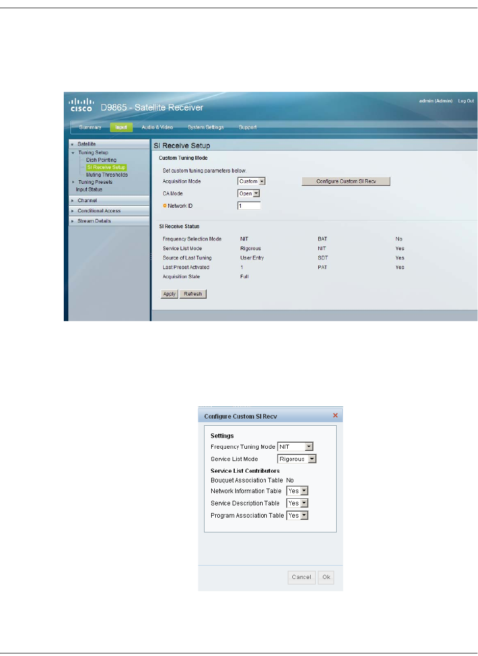
5-16 D9865 Satellite Receiver Installation and Operation Guide 4035197 Rev C
Setting up SI Receive Parameters
To Set up the SI Receive Parameters
Proceed as follows to setup the SI Receive parameters:
1. From the user interface of the D9865, click Input > Satellite, expand Tuning
Setup and then click SI Receive Setup. The SI Receive Setup page is displayed.
2. From the Acquisition Mode drop-down list, select the mode used to build
channel lists from allowed service lists. The selections are Auto, Basic, or
Custom. The default is Basic.
If you select Custom, click Configure Custom SI Recv and the Configure
Custom SI Recv window opens:
3. Set the Frequency Tuning Mode, which determines whether the receiver is to
be tuned to the received signal using the NIT or User Cfg (user configurations).
4035197 Rev C D9865 Satellite Receiver Installation and Operation Guide 5-17
Setting up SI Receive Parameters, Continued
4. The Service List Mode determines which tables to use to obtain tuning and
channel lists.
Select Rigorous if all the default settings must be present in the received signal.
Select Degraded if only the table parameters present in the received signal will
be used to install the receiver. The default is Rigorous.
5. The Service List Contributors section allows you to set up custom properties.
The following table shows some possible configurations for the allowed service
lists and the different frequency tuning settings.
Note: You cannot change the Bouquet Association Table value. It is not
supported in the current release.
6. Click OK.
7. Select the Conditional Access (CA) Mode that determines which programs can
be viewed via the receiver. You can select Std (preferred) or Open.
Important: In Open mode, the receiver ignores inconsistent scrambling
descriptions within the signal. Operating in this mode may cause the decoder
not to respond to certain advanced uplink controlled features, such as service
replacement.
8. Enter the Network ID, obtained from your service provider.
9. The SI Receive Status section displays all the current SI Receive settings. It also
displays the source of last tuning, the last Preset Number activated, and the
current settings of the allowed services (BAT, NIT, SDT, PAT).
10. Click Apply.
Allowed Service Lists Custom
Bouquet Association Table (BAT)
(not supported)
N
Network Information Table (NIT) N
Service Description Table (SDT) N
Program Association Table (PAT) Y
Frequency Tuning mode User Cfg

5-18 D9865 Satellite Receiver Installation and Operation Guide 4035197 Rev C
Setting up Muting Threshold Controls
To Set Up the Muting Threshold Controls
Proceed as follows to set up the muting threshold controls:
1. From the user interface of the D9865, click Input > Satellite, expand Tuning
Setup and then click Muting Thresholds. The Muting Thresholds page is
displayed.
2. Select Enable Threshold Muting to mute the transport stream and audio in the
event of an unstable signal, poor signal, or no signal condition. The default is
selected.
3. The Transport Mute and Restore for both DVB-S C/N Margin and DVB-S2 C/
N Margin sets how the receiver reacts when the signal quality is severely
degraded when using DVB-S or DVB-S2 modulation. This allows you to set the
transport C/N margin values for the receiver. The receiver uses these noise
values/settings as limits during normal operation to determine whether to mute
the transport in the event of a noisy signal, poor signal or no signal condition.
The Transport Mute is the lower limit for the transport C/N margin setting. The
transport will be muted when the C/N margin is below the mute setting for a
nominal delay of 1 second. The delay is between the time the condition is first
detected and the time the transport is muted. The adjustable operating range is
from -5.0 to 20.0 dB. The default setting for Transport Mute is 0.0.
4035197 Rev C D9865 Satellite Receiver Installation and Operation Guide 5-19
Setting up Muting Threshold Controls, Continued
The Transport Restore is the upper limit for the transport C/N margin setting.
The transport will be un-muted (e.g., restored) when the C/N margin rises
above the Transport Restore setting for a nominal delay of 8 seconds. The delay
is between the time the condition is first detected and the time the transport is
muted. The adjustable operating range is from -5.0 to 20.0 dB. The default
setting for Transport Restore is 0.1.
Transport Default C/N Margin Relationship
4. The Audio Mute and Restore for both DVB-S C/N Margin and DVB-S2 C/N
Margin sets the Audio channel Mute and Restore C/N margin values (limits) to
mute audio when the signal quality is severely degraded when using DVB-S or
DVB-S2 modulation.
The Audio Mute is the lower limit for the audio C/N margin setting. Audio will
be muted when the C/N margin is below the Cutoff setting for a nominal delay
of 4 seconds. The delay is between the time the condition is first detected and
the time the transport is muted. The adjustable operating range is from -5.0 to
20.0 dB. The default setting for Audio Mute is 0.0.
The Audio Restore is the upper limit for the audio C/N margin setting. Audio
will be un-muted (e.g., restored) when the C/N margin rises above the Restore
setting for a nominal delay of 8 seconds. The delay is between the time the
condition is first detected and the time the transport is restored. The adjustable
operating range is from -5.0 to 20.0 dB. The default setting for Audio Restore is
0.1.
Transport Mute
Transport Restore
0.1
0.0 Transport Muted
Transport Restored
Transport
C/N Margin
5-20 D9865 Satellite Receiver Installation and Operation Guide 4035197 Rev C
Setting up Muting Threshold Controls, Continued
Audio Default C/N Margin Relationship
5. Click Apply. If you want to restore the transport stream and audio C/N margin
options to their factory set (default) values, click Reset Defaults.
Audio Mute
Audio Restore
0.1
0.0 Audio Muted
Audio Restored
Audio
C/N Margin

4035197 Rev C D9865 Satellite Receiver Installation and Operation Guide 5-21
Setting up the Tuning Presets/LNB
To Set Up the Tuning Presets
The Tuning Presets page allows you to select or configure up to 64 network presets.
Your receiver may be shipped pre-configured with a number of network presets.
You can configure the network preset to use one of 10 LNB configurations.
Proceed as follows to set up the Tuning Preset/LNB:
1. From the user interface of the D9865, click Input > Satellite > Tuning Presets.
The Tuning Presets page is displayed.
2. Select the Preset Number, a value in the range from 1 to 64.
3. Enter the Preset network Name.
4. Enter the Network ID, obtained from your service provider.
5. Enter the LNB Configuration, a value in the range from 1 to 10.
6. Select the Modulation Type for the received signal (DVB-S or DVB-S2).
7. Set the Downlink Frequency used by the receiver for tuning the received digital
signal. You can enter a value in the range from 0.0 to 15.0 GHz. The formula for
C-Band is: Downlink Freq = LO Freq - L-Band Freq. The formula for Ku-Band is
Downlink Freq = LO Freq + L-Band Freq.

5-22 D9865 Satellite Receiver Installation and Operation Guide 4035197 Rev C
Setting up the Tuning Presets/LNB, Continued
8. Type the Symbol Rate. The symbol rate must match that of transmitted signal.
You can enter a value in the range from 1.0 to 45.0 MS/s for DVB-S or 1.0 to 31.0
MS/s for DVB-S2.
9. The Last Activated Preset displays the number of the last activated preset.
10. The Current Input Status section displays the current RF Tuning Status
information, including the downlink frequency and signal status.
11. Click Apply to Preset to apply the settings to the receiver.
Click Activate to choose the preset. This will activate the currently displayed
preset as the active preset. You will be prompted to accept the new preset and
warned that service interruption will occur.

4035197 Rev C D9865 Satellite Receiver Installation and Operation Guide 5-23
Setting up LNB Presets
To Set Up the LNB Presets
Proceed as follows to set up the Dish Presets:
1. From the user interface of the D9865, click Input > Satellite, expand Tuning
Presets and then click LNB Presets. The LNB Presets page is displayed.
2. Select the LNB Configuration number, identifying the current present LNB
configuration. You can select a number in the range from 1 to 10.
3. The LNB Power setting determines if power is provided via the input to an
external LNB connection.
You can set the LNB Power to Off, 18-H, 13-V, H-NIT, or V-NIT. The default is
18-H. If LNB Power is set to V-NIT or H-NIT, the signal polarization is
automatically read from the NIT. Power will not be applied to the LNB if LNB
Power is set to Off.
Note: LNB power must be on if DiSEqC is required.
For more information, see LNB Power Settings, on page 4-25.
4. The LO Select is only applicable for dual-band LNB applications. It sets whether
or not the 22 KHz tone is available. The selections are On, Off, or Auto (if
downlink frequency is greater/less than the crossover frequency, the 22 KHz
tone is automatically set to on/off). The default is Off.

5-24 D9865 Satellite Receiver Installation and Operation Guide 4035197 Rev C
Setting up Dish Presets, Continued
5. Set the Local Oscillator Frequency #1 (LO Freq 1), which sets the satellite
antenna LNB local oscillator #1 frequency. For C-Band application, set to 5.15
GHz. For Ku-band single LNB, enter LO Freq and set LO Freq 2 and Crossover
Frequency to 0.0. For Ku-band dual LNB, enter LO Freq 1, LO Freq 2 and
Crossover Frequency. The default is 10.75 GHz.
6. Set the Local Oscillator Frequency #2 (LO Freq 2), which sets the satellite
antenna LNB local oscillator #2 frequency. This option is only used in dual-band
LNB applications. LO Freq 2 must be greater than LO Freq 1. The default is 0.0
GHz.
7. Enter the Crossover. This is an internal threshold frequency used for selecting
the LO1 or LO2 frequency, depending on the current downlink frequency
settings. This option is only used in dual-band LNB applications. The default is
0.0 GHz.
8. Enable or disable the Digital Satellite Equipment Satellite Control (DiSEqC).
Note: This must be enabled to control the DiSEqC switch. LNB Power must be
on to use this setting. Refer to http://www.eutelsat.com/satellites/4_5_5.html
for more information.
9. In the DiSEqC Switch drop-down list, select a port on the LNB switch, if used
(Off, A to P).
10. Click Apply to Preset.
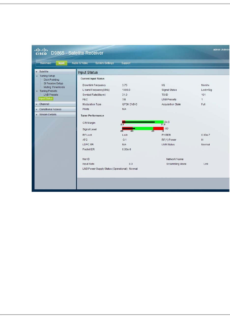
4035197 Rev C D9865 Satellite Receiver Installation and Operation Guide 5-25
Viewing Input Status
To View the Input Status
Proceed as follows to view the Input Status page:
From the user interface of the D9865, click Input > Satellite > Input Status. The
Input Status page is displayed.
The Input Status page displays the active input port receiving the signal.
The Current Input Status section displays current RF Tuning Status information,
including the downlink frequency and signal status.
The Tuner Performance section displays the satellite dish status, such as the C/N
Margin and Signal Level.
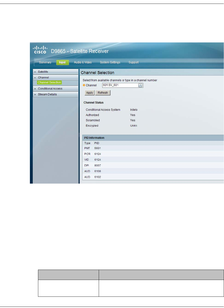
5-26 D9865 Satellite Receiver Installation and Operation Guide 4035197 Rev C
Setting the Channel Information
To set the Channel Selection
Proceed as follows to select a channel and view the channel information:
1. From the user interface of the D9865, click Input > Channel. The Channel
Selection page is displayed.
2. Select the Channel number from the list of available channels.
Note: Subscriber uplink services made available to your satellite receiver are
associated with virtual channels. These channels can include video, audio, and/
or data services. All authorized virtual channel services are provided via
PowerVu Network Centre (PNC) system software and broadcast facility
equipment, and are decoded by the receiver. You can view available subscriber
services for any received virtual received channel on this menu and tune to the
selected channel by entering the particular channel number.
3. Click Apply. The channel is selected and the selected channel is displayed on-
screen.
4. The Channel Status section displays the following information:
Channel Information Description
Conditional Access
System
Indicates the type of CA used for the received
signal.

4035197 Rev C D9865 Satellite Receiver Installation and Operation Guide 5-27
5. The PID Information section displays the PIDs associated with a selected
channel.
Authorized Indicates whether the receiver is authorized to
receive the signal.
Scrambled Indicates whether the received signal is scrambled.
Encrypted Indicates whether the received signal is encrypted.
Channel Information Description
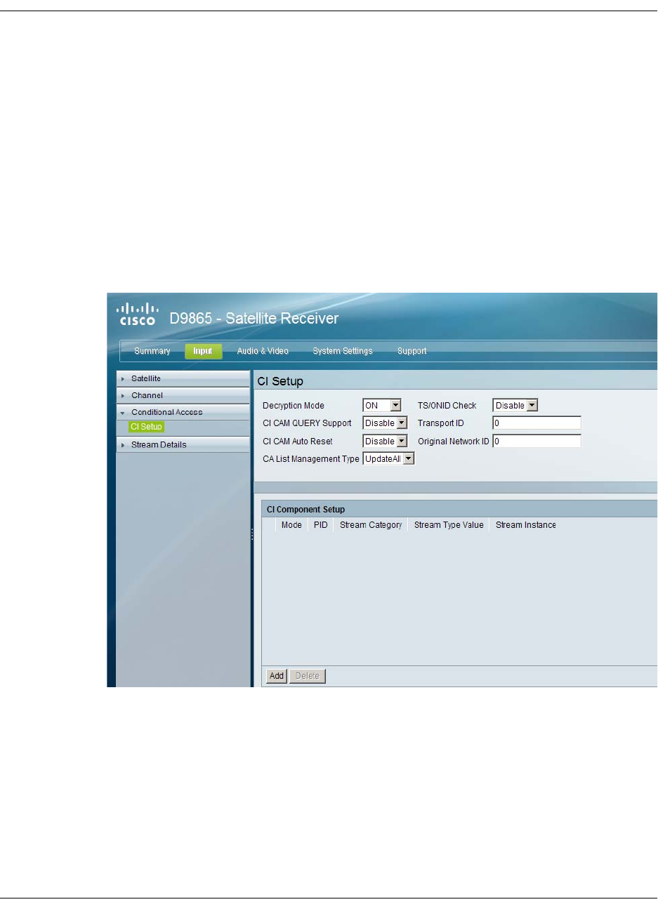
5-28 D9865 Satellite Receiver Installation and Operation Guide 4035197 Rev C
Configuring the Common Interface (CI) Information
To Configure the Common Interface (CI)
The Common Interface (CI) slot is located behind the door on the front panel. They
allow use of a CAM (Conditional Access Module) Smartcard to decrypt purchased
programming.
Note: You must be authorized to view the programming available via the Smart
Card from your service provider.
CAMs must be purchased from Cisco. For a list of the supported CAMs, see
Common Interface Modules, on page 3-5.
Proceed as follows to configure the CI settings:
1. From the user interface of the D9865, click Input > Conditional Access. The CI
Setup page is displayed.
2. The Decryption Mode determines whether to decrypt the program on the
selected CAM (Yes, No, Comp). Select Comp to customize the PID or stream
type to decrypt.
3. Select Enable in the CI CAM QUERY Support drop-down list to query the
CAM prior to decryption to ensure that the card can be decrypted. The default is
Disable.
4. Select Enable in CI CAM Auto Reset to automatically reset the card. The default
is Disable.
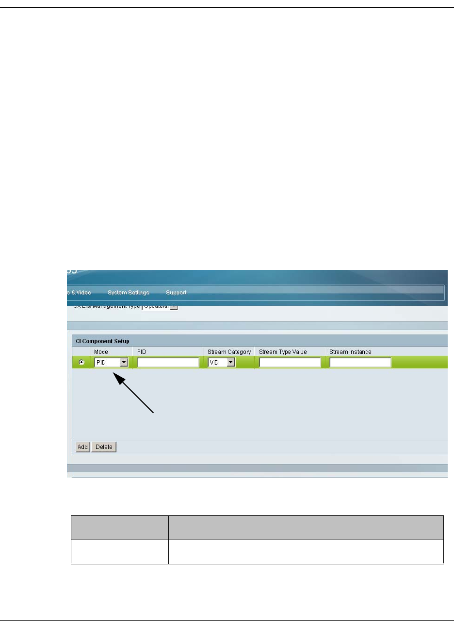
4035197 Rev C D9865 Satellite Receiver Installation and Operation Guide 5-29
Configuring the Common Interface (CI) Information, Continued
5. In the CA List Management Type drop-down list, select AddDel (Default) to
add or delete programs individually in the CAM. Set to Update All to
automatically update and reset all the programs each time you add or modify
the programs available via the CAM.
6. Select Enable in the TS/ONID Check drop-down list if you want to restrict the
incoming transport stream to the transport ID and transport original network ID
listed below. If the incoming stream does not match the specified transport
stream, the CAM will not decrypt. The default is Disable.
7. Set the Transport ID and Original Network ID if you had set the TS/ONID
Check to Enable. If the incoming stream does not match the specified IDs here,
the CAM will not decrypt. You can enter a value in the range from 0 to 65535.
8. If you selected Comp as the Decryption Mode, you can insert and maintain
customized records in the CI Component Setup section. Each record customizes
the PID or stream type to decrypt. The Index number is a read only field that
indicates the record number. You can maintain up to 32 records.
To insert a new record, click Add. A new row appears at the top of the table (see
below).
There are various configurations when creating a new record.
The following table summarizes the various methods:
If you set by Parameter Settings
PID Set Mode to PID and enter PID number.
New Record
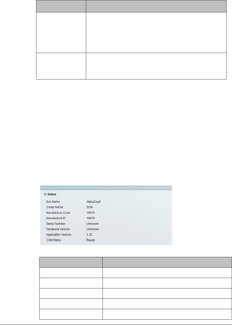
5-30 D9865 Satellite Receiver Installation and Operation Guide 4035197 Rev C
9. If you know the PID number, ensure that PID is selected under Mode and enter
the appropriate PID number. Click Apply.
10. To enter the stream type, select Stream under Mode, select the stream type in
the Stream Category (Vid, Aud, Subt, or TTX) and enter the instance of the
stream type in Stream Instance. You can enter a range from 1 to 64. Click Apply.
11. If you do not know the stream type, you can specify a specific hex value as the
stream type. Select Stream under Mode, select User under Stream Category,
enter the hex value of the stream under Stream Type value (hex) and the
instance of the customized stream type in Stream Instance. You can enter a two
digit hexadecimal value for the Stream Type and a range from 1 to 64 for the
Stream Instance. Click Apply.
12. To delete a record, identify the record you want to remove and click Delete.
13. Scroll down to view the CI Status information:
The following table describes the CI Status:
Stream Type Set Mode to Stream, select Stream Category (audio,
video, subtitle, ttx, or user) and enter Stream Instance of
the stream type.
There is an additional configuration if you select user as
the Stream Category (see below).
Stream Type: User Set Mode to Stream, Stream Category to User, manually
enter the stream code in Stream Type Value, and then
the Stream Instance of the stream type.
CI Status Description
Sys Name System name of the CAM.
Comp Name The company name of the CAM.
Manufacture Code The manufacturer’s code.
Manufacture ID The factory loaded application number of the CAM.
Serial Number The unique serial number of the CAM.
If you set by Parameter Settings
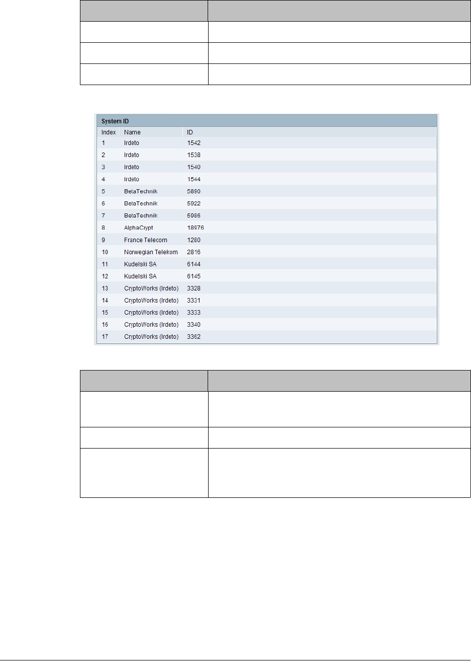
4035197 Rev C D9865 Satellite Receiver Installation and Operation Guide 5-31
14. Scroll down to view the System ID information.
The following table describes the System ID information:
15. Click Apply.
Hardware Version The hardware version number of the CAM.
Application Version The software version number of the CAM.
CAM Status Status of the CAM (Ready or Not Ready).
System ID Description
Index Indicates the customized record number (1 to 64, up
to 32 records for each CAM).
Name System name of the CAM.
ID Displays the CA system identification ID of the
CAM. Some CAMs may support multiple CA
system IDs.
CI Status Description

5-32 D9865 Satellite Receiver Installation and Operation Guide 4035197 Rev C
Viewing the PSI Tables
To View the PSI Tables
Proceed as follows to view the PSI tables:
From the user interface of the D9865, click Input > Stream Details > PSI Tables.
The PSI Tables page is displayed.
The PSI Table is read-only. The following is a list of the various columns:
Abbreviation Description
Table Type Table Type (i.e., NIT, PMT, etc.)
Table ID Extension MPEG/DVB Table ID
Status Reception Status
Version Table Version number
PID Program PID number
Number of Sections PSI tables are received in sections. This indicates the
section number received. This information is useful
for diagnostics/troubleshooting purposes.
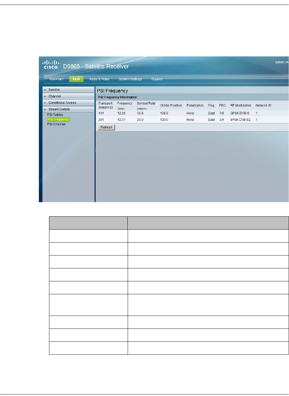
4035197 Rev C D9865 Satellite Receiver Installation and Operation Guide 5-33
Viewing PSI Frequency Information
To View the PSI Frequency Information
Proceed as follows to view the PSI Frequency table:
From the user interface of the D9865, click Input > Stream Details > PSI Frequency.
The PSI Frequency page is displayed.
The PSI Frequency table is read-only. The following is a list of the various columns:
Abbreviation Description
Transport Stream ID Transport ID
Frequency (GHz) Downlink Frequency (GHz)
Symbol Rate (MSym) Symbol Rate (Msym/s)
Orbital Position Orbital Position (in degrees)
Polarization Polarity of the received signal (H,V, or Off)
Flag Satellite position (in degrees), in combination with
the direction (East or West)
FEC Forward Error Correction inner code rate
RF Modulation Modulator constellation setting
Network ID Original Network ID
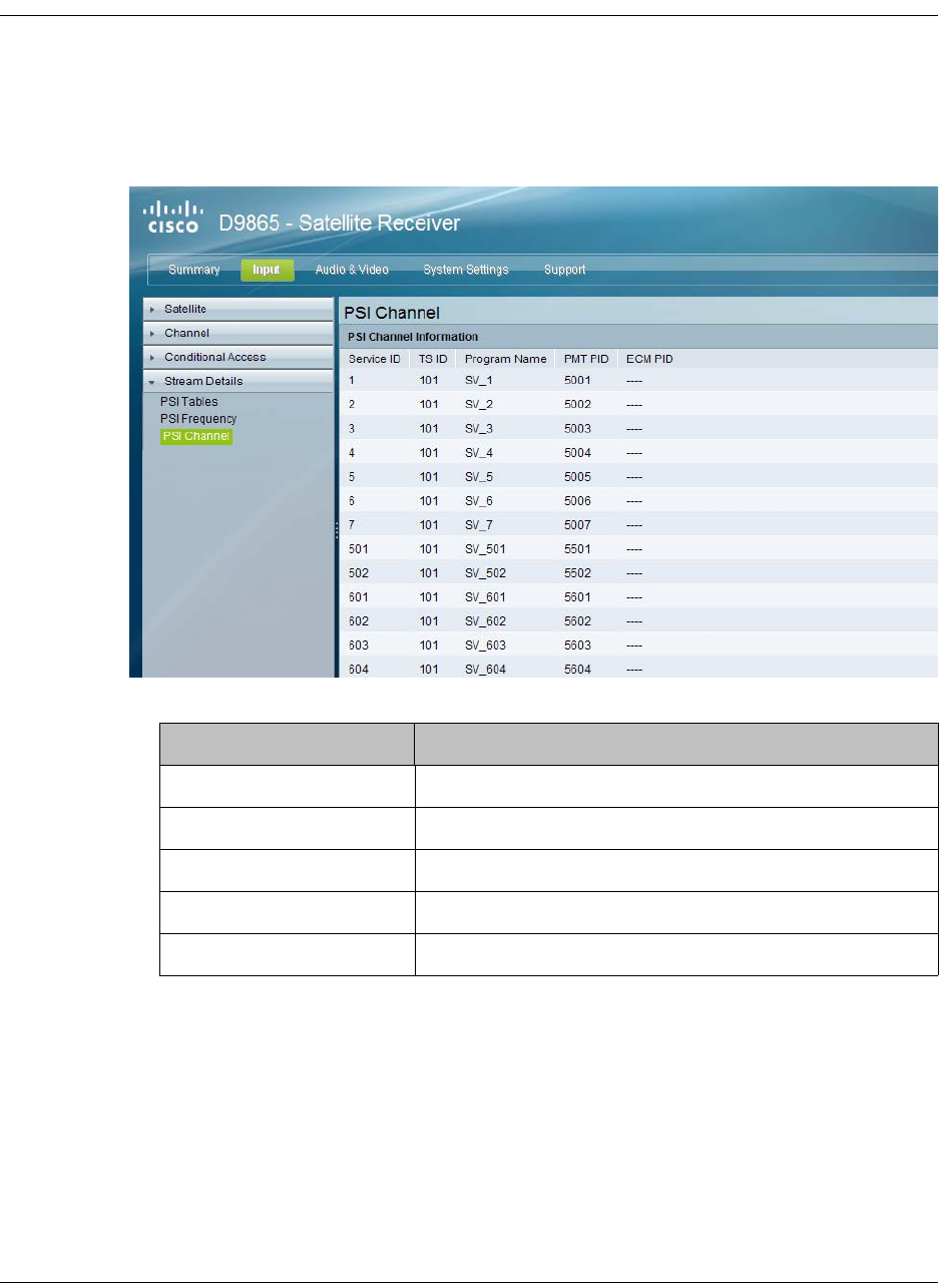
5-34 D9865 Satellite Receiver Installation and Operation Guide 4035197 Rev C
Viewing the PSI Channels
To View the PSI Channels
Proceed as follows to view the PSI Channels table:
From the user interface of the D9865, click Input > Stream Details > PSI Channel.
The PSI Channel page is displayed.
The PSI Channel table is read-only. The following is a list of the various columns:
Abbreviation Description
Service ID Virtual Channel
TS ID Transport Stream ID
Program Name Name of the program
PMT PID Program Map Table PID
ECM PID Entitlement Control Message PID
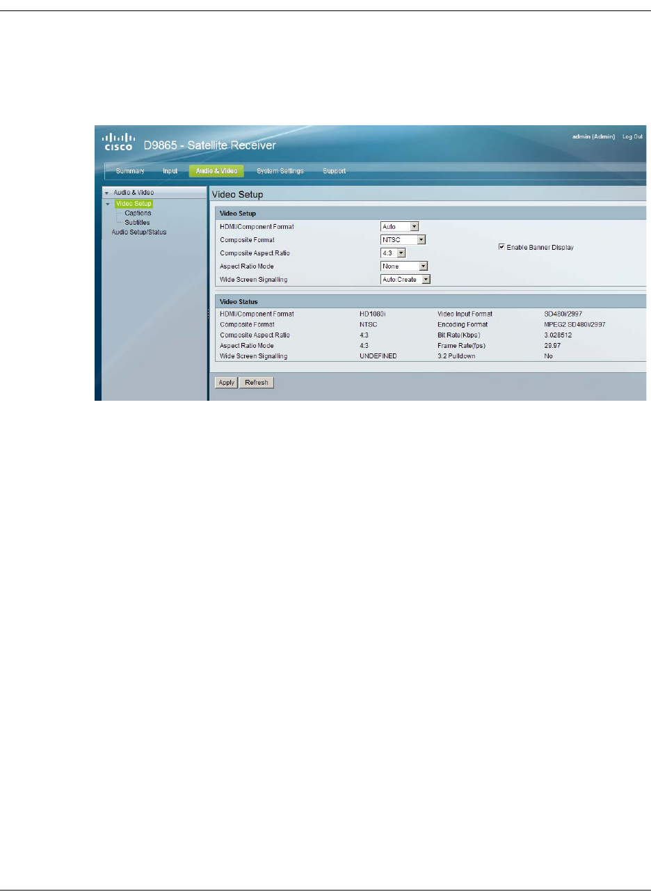
4035197 Rev C D9865 Satellite Receiver Installation and Operation Guide 5-35
Setting up the Video
To Set Up the Video
Proceed as follows to set up the video information:
1. From the user interface of the D9865, click Audio & Video > Video Setup. The
Video Setup page is displayed.
2. Select HD output video format from the HDMI/Component Format drop-down
list (HD 1080i or HD720p). Select Auto for the receiver to automatically detect
the correct HD video format.
3. Set the Composite Format. Select PAL-B/G, PAL-D, or PAL-I for 625-line
systems. Select PAL-M for 525-line format for Brazil. Select PAL-N (AR) for 625-
line format for Argentina. Select NTSC or NTSC-J for 525-line systems. Select
Auto for the receiver to automatically detect the correct SD video format.
4. Select the Composite Aspect Ratio of the intended TV system (4:3 or 16:9).
5. The Aspect Ratio Mode is the conversion that the receiver will perform on the
incoming signal for the picture to be displayed correctly (i.e., to correspond to
the aspect ratio of your TV) on your TV, based on your selection.
The options are None, Auto, Auto AFD, 16:9 L/B, 4:3 P/B, 14:9, 4:3 CCO, and
16:9 SCALE. The default is None.
Note: For the actual conversion performed, refer to Actual Conversion Table,
on page 4-35.
5-36 D9865 Satellite Receiver Installation and Operation Guide 4035197 Rev C
Setting up the Video, Continued
6. Select the Wide Screen Signalling output mode. It is used to select how the
receiver affects PAL WSS when it is present in the VBI. The table below
describes each of the options. The default is Auto.
7. Select Enable Banner Display to display the signal status and other information
at the top of the screen.
8. The Video Status section displays the current video information, such as the
aspect ratio mode, encoding format, and bit rate.
9. Click Apply.
WSS Mode Description
Passthrough Passes WSS (unmodified, as received by the D9865
receiver) on VBI LIne 23 when present
Auto:Create Creates WSS to output the correct aspect ratio, when
performing aspect ratio conversion, otherwise it is
passed through.
Auto:Modify Modifies WSS to output the correct aspect ratio, when
performing aspect ratio conversion, otherwise it is
passed through
Suppress Disables Line 23 VBI processing. WSS is not output on
line 23.
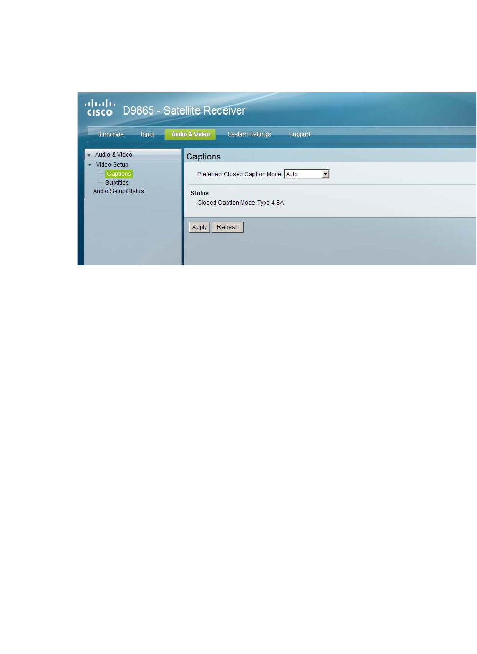
4035197 Rev C D9865 Satellite Receiver Installation and Operation Guide 5-37
Configuring Captions
To Set Up the Caption Parameters
Proceed as follows to set up the caption parameters:
1. From the user interface of the D9865, click Audio & Video, expand Video Setup
and then click Captions. The Captions page is displayed.
2. Select the Preferred Closed Caption Mode. There are multiple in the stream.
The default is Auto.
Note: SA Custom is not supported when telecine video coding is enabled.
3. The Status section displays the actual caption mode used. This is read-only.
4. Click Apply.
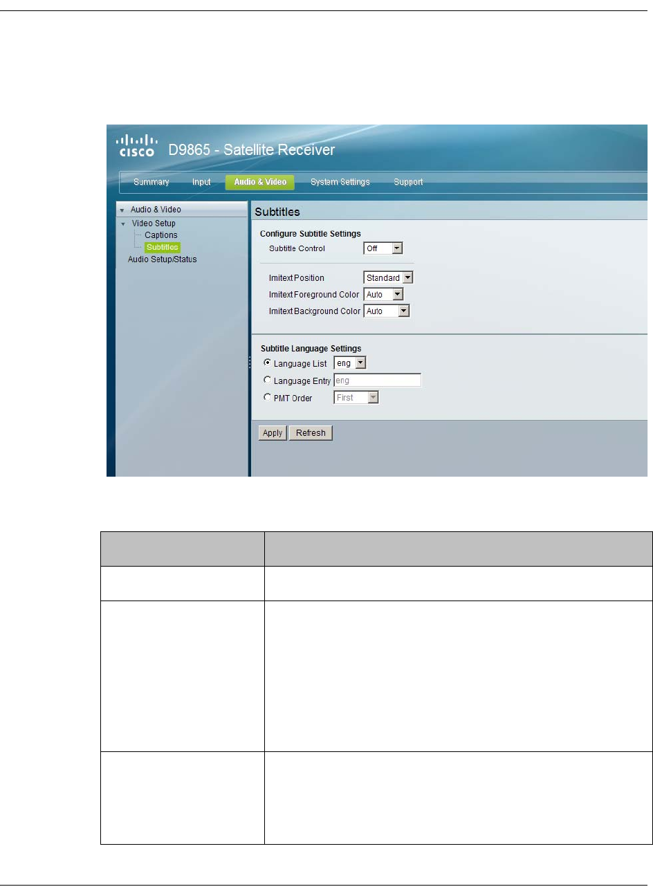
5-38 D9865 Satellite Receiver Installation and Operation Guide 4035197 Rev C
Setting up Subtitles
To Set Up Subtitles
Proceed as follows to set up the subtitles:
1. From the user interface of the D9865, click Audio & Video, expand Video Setup
and then click Subtitles. The Subtitles page is displayed.
2. Select the Subtitle Control to use to display the program subtitles. The
following table describes each of the available options.
Op Mode Selection Description
Off No subtitles are displayed.
On Functions as an “Auto” setting. DVB subtitles are
displayed when only DVB subtitles are transmitted on
the channel, and likewise, Imitext subtitles are
displayed when only Imitext subtitles are transmitted
on the channel. When both DVB and Imitext subtitles
are available on the same channel, only DVB subtitles
will be displayed.
DVB Displays only DVB subtitles. For example, if DVB is
selected, but both DVB and Imitext subtitles are being
transmitted on the same channel, only DVB subtitles
will be displayed.
4035197 Rev C D9865 Satellite Receiver Installation and Operation Guide 5-39
3. Select the Imitext Position of the on-screen subtitle text. Select Standard for
subtitles to appear on screen in the same position as output from other PowerVu
receivers. Select Extended to position subtitles on screen according to the Imitext
(extended) specification.
4. The Imitext Foreground Color sets the color of Imitext subtitles only. Auto
displays text in the color transmitted by the subtitling equipment. Yellow and
White overrides the color set by the uplink and display text in the selected color.
5. The Imitext Background Color sets the background on which Imitext subtitles
are displayed. The following table identifies the affect each setting has on the
displayed subtitle text:
6. In the Subtitle Language Settings section, select the language type to display
the subtitles. The default is Language List. Language Entry and PMT Order are
more applicable for advanced applications. The following table describes each
of the available options and how to set them:
Imitext Displays only Imitext subtitles. For example, if Imitext
is selected, but both DVB and Imitext subtitles are being
transmitted on the same channel, only Imitext subtitles
will be displayed.
Op Mode Selection Description
BackGnd Option Description
Auto Displays background in same shade transmitted by the
subtitling equipment.
Shadow Applies an outline to the right side of each text
character. No background box is applied to subtitles, i.e.,
text is visible directly on top of video.
Opaque Applies a black box to each text character.
Semi Applies a semi-transparent box to subtitle text.
None No shadow or outline is applied to subtitle text.
Select Language By Option Description
Language List Each subtitling PID can contain multiple
languages. Use this setting to select the
language from the Language List by
scrolling through the available selections. If
Language List is selected, PMT Order and
Entry fields are not used.

5-40 D9865 Satellite Receiver Installation and Operation Guide 4035197 Rev C
7. Click Apply.
Language Entry Use this setting with Entry to directly enter
the language code when the language you
want is not in the list. In this case enter the
three-character code provided by your
uplink service provider (e.g., eng for
English).
PMT Order Use this setting to select one of up to eight
languages as assigned in the PMT for the
tuned channel on the receiver. Scroll
through the PMT Order to select the correct
language within the order (i.e., First to
Eighth), available from your uplink service
provider.

4035197 Rev C D9865 Satellite Receiver Installation and Operation Guide 5-41
Setting up Audio
To Set Up the Audio
Proceed as follows to set up the audio:
1. From the user interface of the D9865, click Audio & Video > Audio Setup/
Status. The Audio Setup/Status page is displayed.
Set the compressed audio type from the Digital Audio Setting drop-down list
(PCM, Dolby Digital, Compressed). The following table displays the effects of
Dolby Audio Preference setting on audio outputs, based on the type of audio being
decoded:
Input/
Output
Digital Audio Preference
PCM Dolby Digital Compressed
S/PDIF HDMI
MPEG LA
(MPEG1 and
MPEG2)
PCM PCM PCM PCM
Dolby Digital PCM Dolby Digital
(follows IEC 61937)
Dolby Digital
(follows IEC
61937)
Dolby Digital
(follows IEC
61937)
Dolby Digital Plus
(< 1.5 Mbps)
PCM Dolby Digital
(follows IEC 61937)
Dolby Digital
Plus (No over-
clocking,
follows SMPTE-
338)
Dolby Digital
Plus (over-
clocking x4,
follows IEC
61937)
5-42 D9865 Satellite Receiver Installation and Operation Guide 4035197 Rev C
2. Set the audio mode (Stereo/Mono), which configures how audio received on the
audio input is handled.
Select Stereo (Left and right channels are output on L and R respectively), Mixed
(Left and right channels are combined and output on both L and R), L-Mono
(Left channel is output on L and R), or R-Mono (Right channel is output on L
and R).
3. Select the DRC Mode (RF Mode or Line Mode). RF Mode is normally used for
analog cable modulators, when limited dynamic range is desired. Line Mode is
used when full dynamic range is allowed.
4. Select the PMT Audio Source for the audio channel (None or AUD1 to AUD64).
5. The Volume adjustment for the audio channel ranges from 0 to 60. You can
enter a value or use the provided slider to adjust the volume.
6. The Audio Status section displays the following information:
7. Click Apply.
Dolby Digital Plus
(>= 1.5 Mbps)
PCM Dolby Digital
(follows IEC 61937)
Dolby Digital
(follows IEC
61937)
Dolby Digital
(follows IEC
61937)
MPEG2 AAC,
MPEG4 (AAC and
HEAAC v1 and
v2)
PCM MPEG2 AAC,
MPEG4 (AAC and
HEAAC)
(follows IEC 61937)
MPEG2 AAC,
MPEG4 (AAC
and HEAAC)
(follows IEC
61937)
MPEG2 AAC,
MPEG4 (AAC
and HEAAC)
(follows IEC
61937)
Input/
Output
Digital Audio Preference
PCM Dolby Digital Compressed
S/PDIF HDMI
Audio Status Description
Audio Format The received audio channel format (MPEG, Dolby
Digital, AAC, HEAAC or Dolby Digital Plus).
Bit Rate (Mbps) Audio bit rate of the received audio channel, in
Mbps.
Sampling Frequency
(Hz)
The audio sampling frequency (32, 44.1, or 48 Hz).
Buffer Level (Bytes) The audio input buffer level, in bytes.
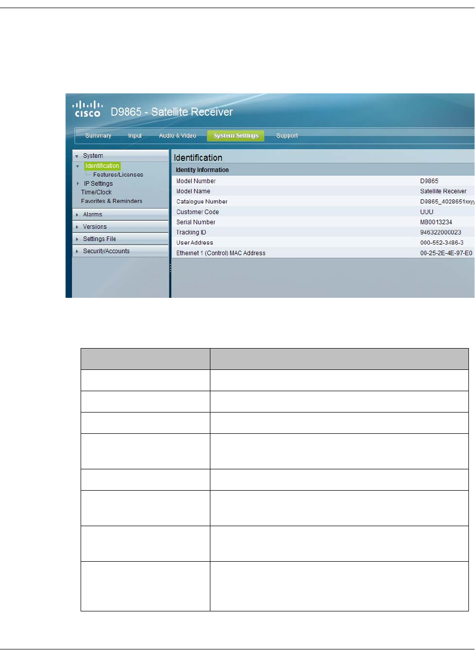
4035197 Rev C D9865 Satellite Receiver Installation and Operation Guide 5-43
Viewing System Information
To View the System Identification Information
Proceed as follows to view the Identification page:
1. From the user interface of the D9865, click System Settings > System>
Identification. The Identification page is displayed.
2. The Identification page displays the parameters associated with the D9865
system, such as model number, customer code, and user address. The following
table displays the system information:
Identity Information Description
Model Number Indicates the model number of the receiver.
Model Name Indicates the model name of the receiver.
Catalogue Number Indicates the catalogue number of the receiver.
Customer Code Indicates the unique customer code assigned to an
organization by Cisco.
Serial Number Indicates the unique serial number of the receiver.
Tracking ID This is the unique Tracking ID number that
identifies the product version.
User Address Indicates the user addresses assigned to the
receiver.
Ethernet 1 (Control)
MAC Address (D9865D
only)
Indicates the MAC addresses assigned to the
Ethernet interface at the time of manufacture.
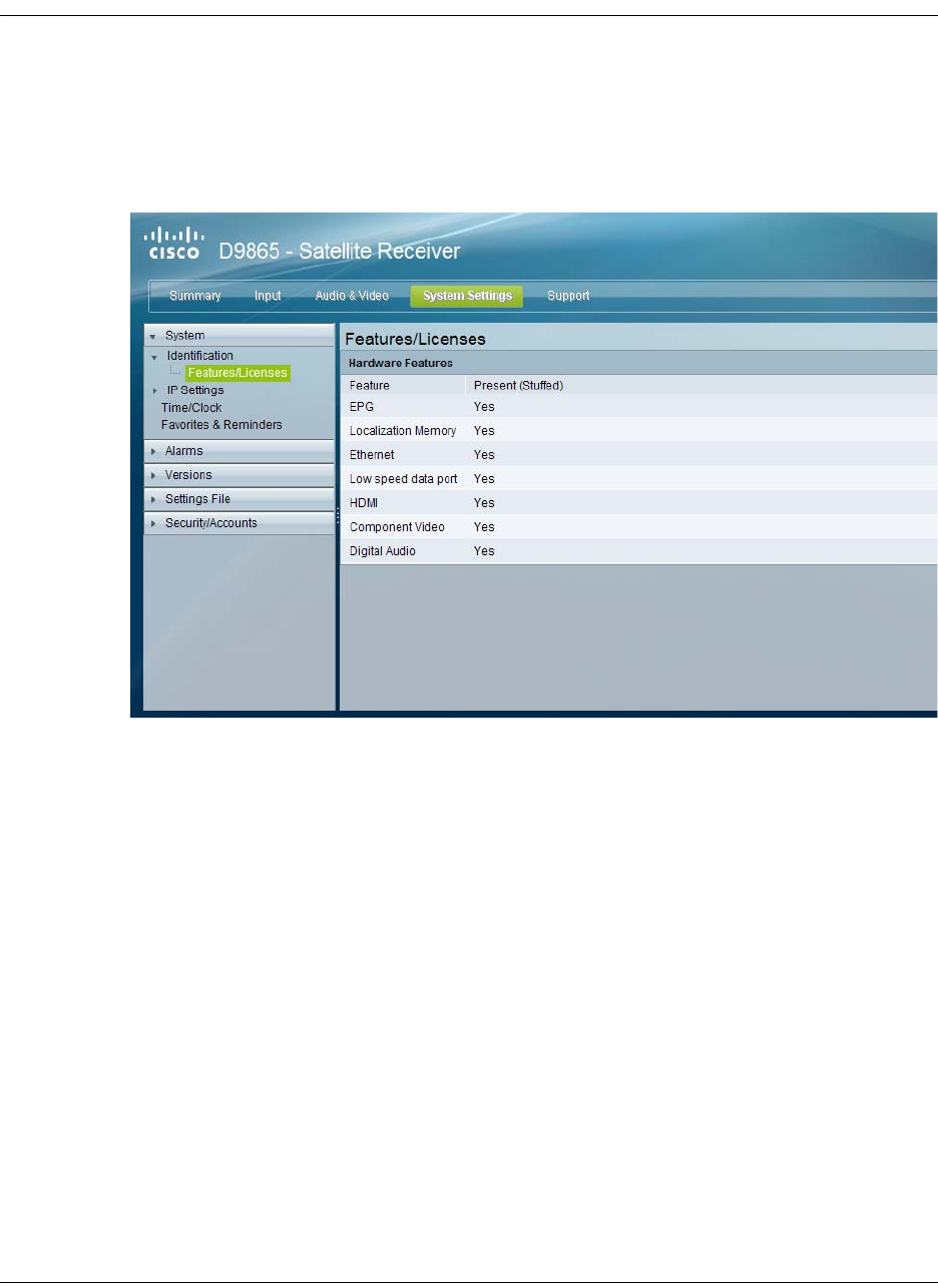
5-44 D9865 Satellite Receiver Installation and Operation Guide 4035197 Rev C
Viewing Features/Licenses
To View the Features or License Information
Proceed as follows to view the features or license information:
From the user interface of the D9865, click System Settings > System, expand
Identification and then click Features/Licenses. The Features/Licenses page is
displayed.
The Hardware Features section displays the hardware options installed in the
current D9865 satellite receiver.

4035197 Rev C D9865 Satellite Receiver Installation and Operation Guide 5-45
Setting Up IP Information
To Configure Management and Data Port Settings
Proceed as follows to configure management and data port settings:
1. From the user interface of the D9865, click System Settings > System > IP
Settings. The IP Settings page is displayed.
2. For the Management and Data Port Settings, set the following parameters:
Selection Description
IP Address Sets the IP Address for its participation
in a Network environment. The IP
Address is 12 digits in length
(###.###.###.###).
IP Mask Sets Subnet Mask for its participation in
a Network environment. You can enter
a value in the range from 8 to 32.
Gateway Address Sets the Network Gateway Address on
the Network, used to expose the
receiver to a WAN.

5-46 D9865 Satellite Receiver Installation and Operation Guide 4035197 Rev C
Setting Up IP Routing
To Set Up IP Routing
Proceed as follows to configure the IP Routing settings:
1. From the user interface of the D9865, click System Settings > System, expand IP
Settings and then click IP Routing. The IP Routing page is displayed.
2. The MPE Data Filter Mode sets whether all the MPE data is forwarded
(Forward All) via the Gateway. It can forward up to 5 PIDs at the maximum bit
rates shown in the following table. Otherwise, select Forward None.
3. Set the MPE Optimization setting. Select High Bitrate (default) to accumulate
the IP packets before they are processed in short bursts, increasing the allowable
bit rate of MPE data. Select Low Jitter to emit the IP packets in a constant
stream, resulting in low latency.
MPE Bit Rate No
Decoding
5 Mbps SD
Video Decoded
20 Mbps HD
Video Decoded
Multicast 30 Mbps 20 Mbps 15 Mbps
Unicast 20 Mbps 15 Mbps 10 Mbps
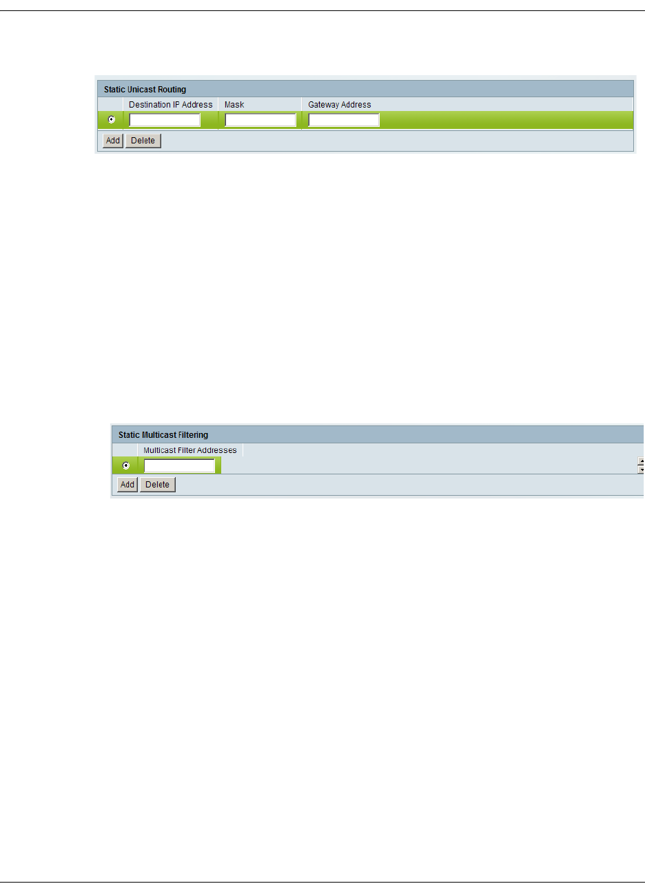
4035197 Rev C D9865 Satellite Receiver Installation and Operation Guide 5-47
Setting Up IP Routing, Continued
4. The Static Unicast Routing displays the static unicast routing addresses for the
MPE data. To add a new address, click Add. The following is displayed:
•Set the Destination IP Address for its participation in a Network
environment. The address must be 12 digits in length, in the following format:
###.###.###.###.
• Set the subnet Mask for its participation in a Network environment, from 8 to
32.
•Set the network Gateway Address used to expose the receiver to a WAN. The
address must be 12 digits in length, in the following format:
###.###.###.###.
•Click Add.
• To remove an address entry, select the entry and click Delete.
5. The Multicast Filtering Addresses section lists the multicast destination IP
addresses. To add a new address, click Add. The following is displayed:
•Enter a Multicast Filter Address and click Add.
• To remove an address entry, select the entry and click Delete.
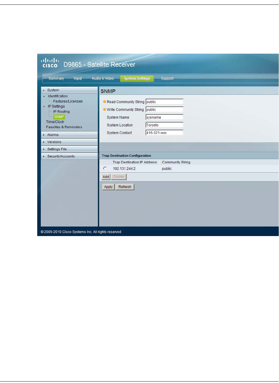
5-48 D9865 Satellite Receiver Installation and Operation Guide 4035197 Rev C
Setting Up SNMP and Trap Destinations
To Set Up SNMP
Proceed as follows to configure the SNMP settings:
1. From the user interface of the D9865, click System Settings > System, expand IP
Settings and then click SNMP. The SNMP page is displayed.
2. Set the Read Community String and the Write Community String to public or
a custom string. The SNMP Community Read/Write is used when
communicating with a device within an SNMP environment. These commands
allow you to set the password to read and write data to a device to display
diagnostics traps/alarms. The default community string is public. To set a
custom community string, enter an alphanumeric character string up to 31-
characters in length identifying the password for the device.
Note: The community string is case-sensitive.
3. Enter the System Name, System Location, and System Contact information of
the D9865. The system information is sent to the MIB browser, if applicable. The
MIB Browser is a third party software used to manage SNMP requests. For more
information, contact Cisco customer support.
4. The Trap Destination Configuration section displays a list of trap destination
address and the associated community string.

4035197 Rev C D9865 Satellite Receiver Installation and Operation Guide 5-49
Setting up SNMP and Trap Destinations, Continued
To Add a Trap Destination:
•Click Add in the Trap Destination Configuration section.
•In the Trap Destination IP Address field, enter the destination for SNMP trap
messages for events (i.e., fault messages). The IP address is up to 12 digits in
length (e.g., 155. 128.100.200).
•In the Community String field, set the community string for the associated
trap IP address. You can enter public or a custom string, up to 31 characters.
The default is public.
• To edit/delete an existing trap destination, select the trap destination entry by
clicking on the radio button. Make the necessary changes, or click Delete to
remove the address from the Trap Destination Configuration list.
5. Click Apply.
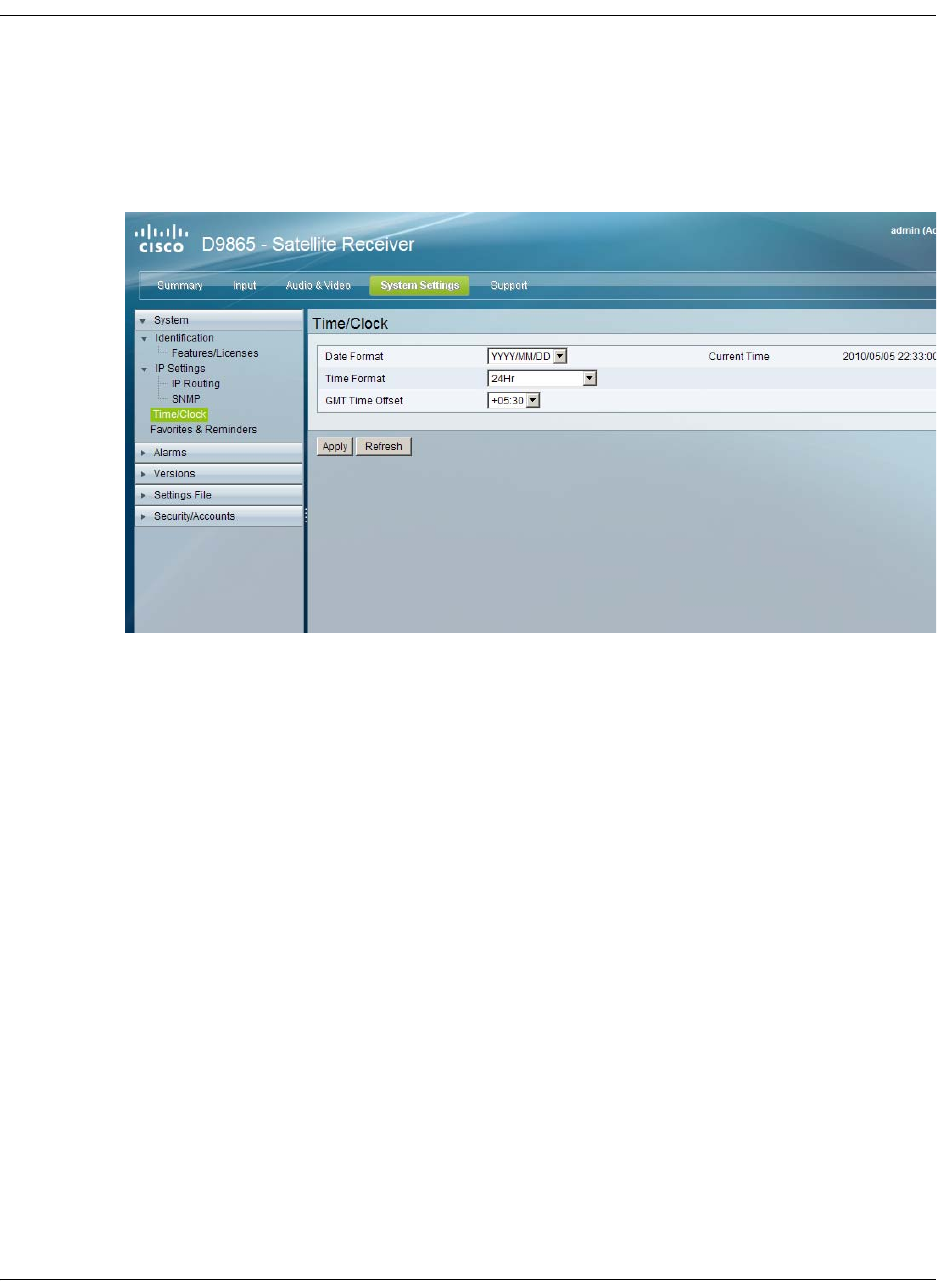
5-50 D9865 Satellite Receiver Installation and Operation Guide 4035197 Rev C
Configuring Time/Clock Information
To Configure the Time/Clock Settings
Proceed as follows to configure the time/clock settings of the D9865 satellite
receiver:
1. From the user interface of the D9865, click System Settings > System > Time/
Clock. The Time/Clock page is displayed.
2. Set the Date Format of the receiver. The following formats are supported:
YYYY/MM/DD, DD/MM/YYYY, MM/DD/YYYY.
3. Set the Time Format of the receiver. Time information is normally broadcast as
part of the transmitted digital signal. It is usually the broadcaster local time
relative to Greenwich Mean Time (GMT). The following formats are supported:
24 Hr, 24 Hr SuspendZero, 12 Hr, 12 Hr SuspendZero.
4. Set the GMT Time Offset. The time is displayed using a time zone instead of
the true local time. If the current broadcast time is not your local time, you must
change this time setting in the range from -12:00 to +13.00 in one hour
increments.
5. The Current Time displays the current date and time, according to the date and
time formats set.
6. Click Apply.

4035197 Rev C D9865 Satellite Receiver Installation and Operation Guide 5-51
Configuring Favorites and Reminders
To Configure Favorites and Reminders
Proceed as follows to configure the favorites and reminder settings of the D9865
receiver:
1. From the user interface of the D9865, click System Settings > System >
Favorites & Reminders. The Favorites & Reminders page is displayed.
2. The Favorites section lists all the favorite profiles configured in the D9865.
Favorites allow you to surf through the channels you have set up as your
favorite channels, skipping over other channels. By default, All Channels
(authorized or unauthorized channels) are displayed. Select Authorized
Channels Only to browse channels that are authorized by your uplink provider
only.
3. The One Button Channel Change allows you to assign a channel to each of the
colored buttons at the bottom of the remote control (see below).
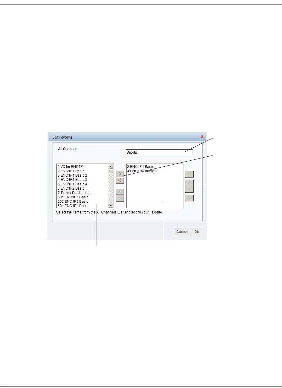
5-52 D9865 Satellite Receiver Installation and Operation Guide 4035197 Rev C
Configuring Favorites and Reminders, Continued
Select a channel to each color as a shortcut for a quick channel change. For
example, if you assign the red button to channel 1, pressing the red button while
watching a different channel at anytime will automatically tune the TV channel
to 1.
Note: You can only use the one button channel change if the screen is
displaying video only. The one button channel change does not work if EPG,
Channel Banner, or on-screen menus are displayed.
4. The Reminders List displays a list of reminders set using the on-screen display.
5. Click Apply.
To Edit a Favorites Profile
1. Select a favorite profile and click Edit. The Edit Favorite screen is displayed. The
following is an example:
2. Edit the channel profile name, if required.
3. Select the channels from the All Channels list and click right to include the
channels in the Favorite profile.
4. Click OK.
Note: To set a favorite profile as an active profile, select the favorite profile and
click Apply.
Moves the selected channels
to the right/left of the channel
lists.
All Channels list Favorite channels list
Moves the order of the favor-
ite channels up or down.
Favorite profile
name
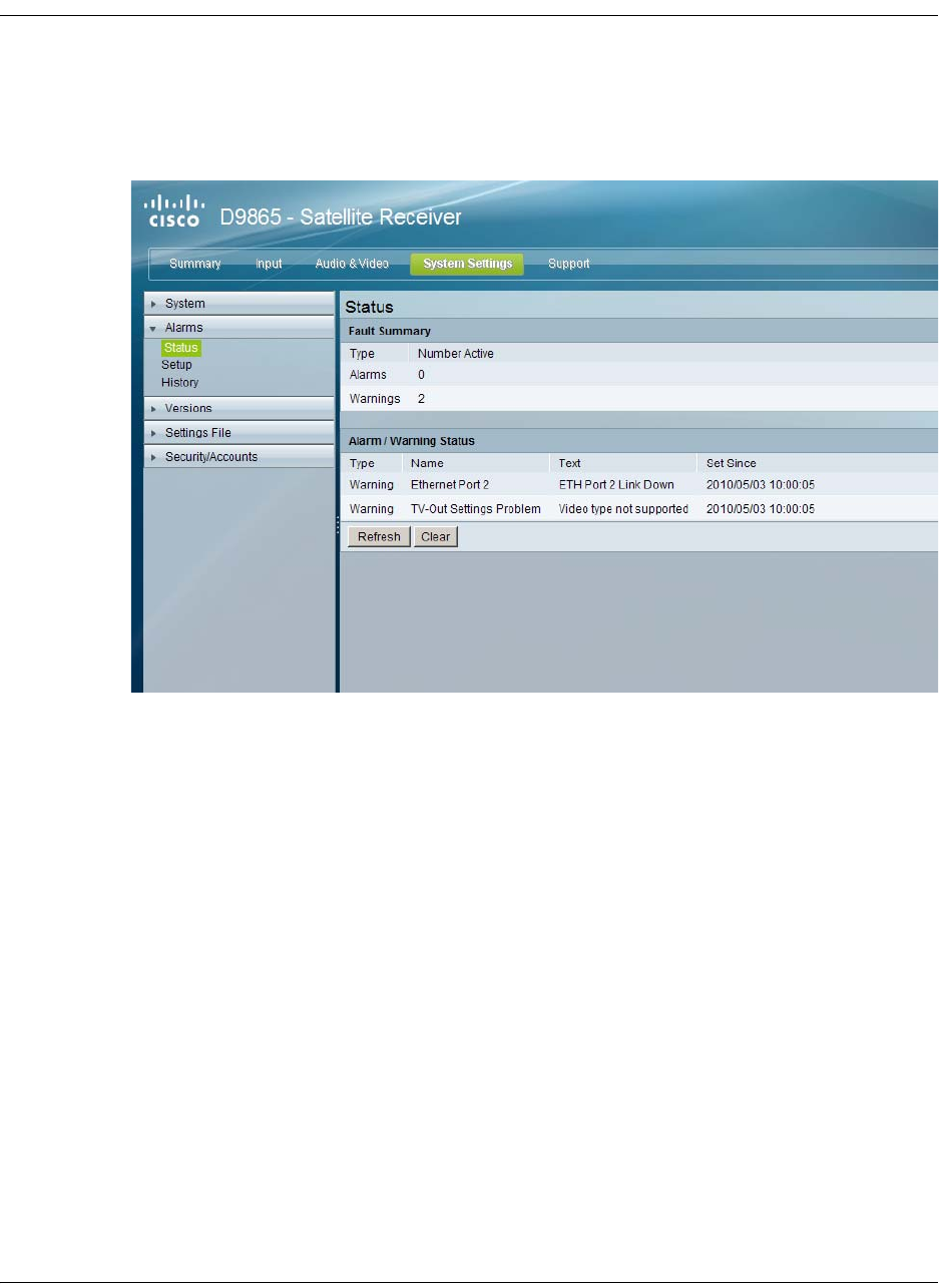
4035197 Rev C D9865 Satellite Receiver Installation and Operation Guide 5-53
Viewing the Alarm/Warning Status
To View the Active Alarm/Warning Status Information
Proceed as follows to view the active alarm and warning messages:
1. From the user interface of the D9865, click System Settings > Alarms > Status.
The Status page is displayed.
2. The Fault Summary section displays the number of currently active Alarms and
Warnings.
3. The Alarm/Warning Status section displays the name of the active alarm/
warning, the alarm/warning message, and the date and time of the alarm. For
more information on alarm messages, refer to Messages, on page 7-2.
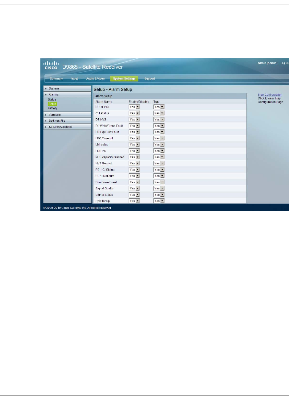
5-54 D9865 Satellite Receiver Installation and Operation Guide 4035197 Rev C
Setting Up Alarms and Warnings
To Set Up Alarms
Proceed as follows to set up the alarms:
1. From the user interface of the D9865, click System Settings > Alarms > Setup.
The Setup - Alarm Setup page is displayed.
2. The Alarm Setup section displays a list of alarm/fault messages. For more
information on alarm messages, refer to Messages, on page 7-2.
3. Set Enable/Disable to Yes and the alarm message will be reported. Set to No
and the fault won’t be reported.
4. Set Trap to Yes and the SNMP trap message will be sent to the trap destination;
otherwise the fault message will be ignored.
Note: This is for D9865D only.
5. Click on the Trap Configuration link to view and/or modify trap destinations.
The link will open the SNMP page. For more information, refer to Setting Up
SNMP and Trap Destinations, on page 5-48.
6. Click Apply.
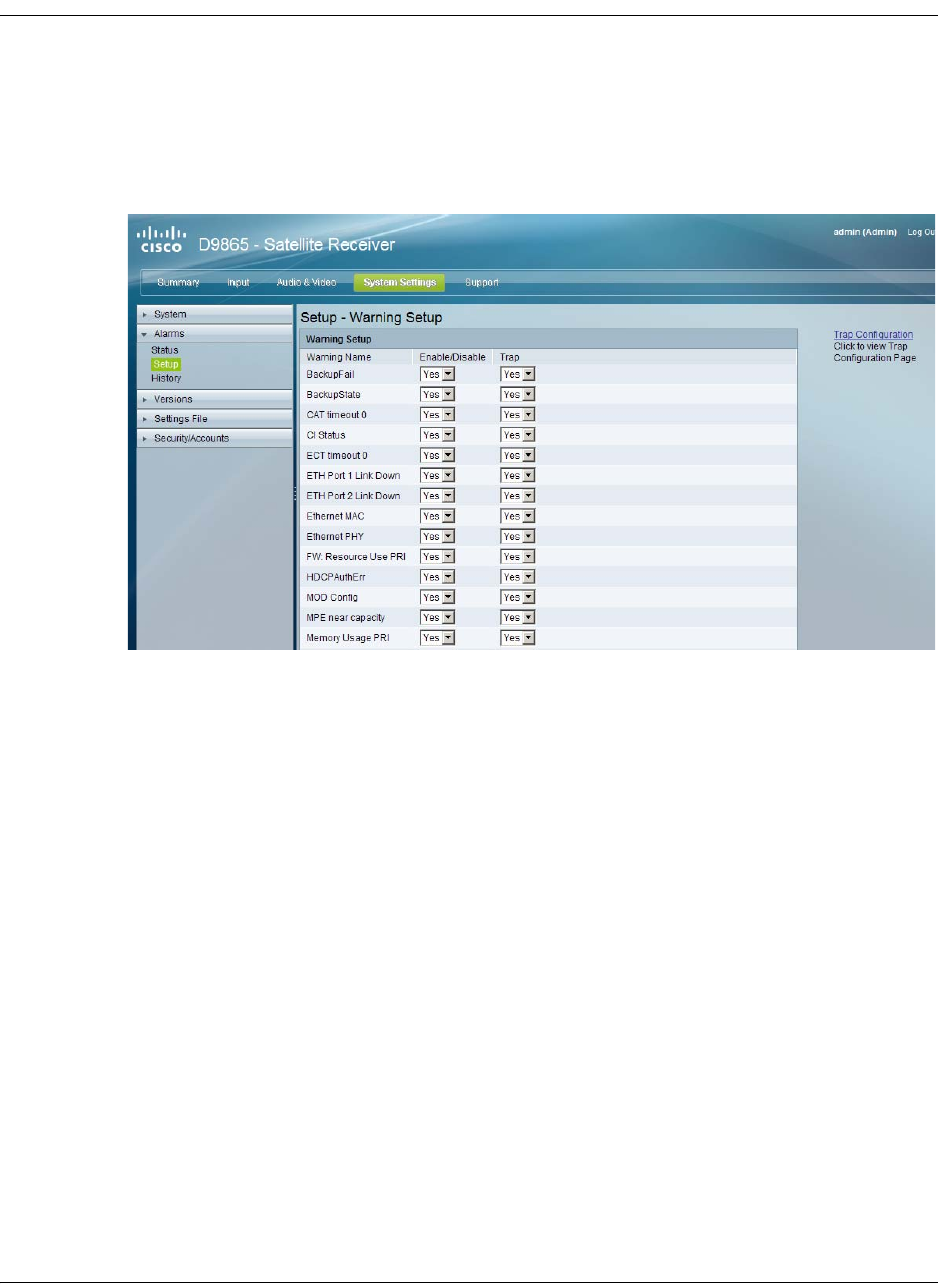
4035197 Rev C D9865 Satellite Receiver Installation and Operation Guide 5-55
Setting Up Alarms and Warnings, Continued
To Set up Warnings
Proceed as follows to set up the warnings:
1. From the Setup - Alarm Setup page, click on the Warning Setup link at the
bottom left hand corner of the page. The Setup - Warning Setup page is
displayed.
2. The Warning Setup section displays a list of alarm/fault messages. For more
information on alarm messages, refer to Messages, on page 7-2.
3. Set Enable/Disable to Yes and the warning message will be reported. Set to No
and the fault won’t be reported.
4. Set Trap to Yes and the SNMP trap message will be sent to the trap destination;
otherwise the fault message will be ignored.
Note: This is for D9865D only.
5. Click on the Trap Configuration link to view and/or modify trap destinations.
The link will open the SNMP page. For more information, refer to Setting Up
SNMP and Trap Destinations, on page 5-48.
6. Click Apply.

5-56 D9865 Satellite Receiver Installation and Operation Guide 4035197 Rev C
Viewing the Alarm/Warning History
To View the Alarm/Warning History Information
Proceed as follows to view the Alarm/Warning History information:
From the user interface of the D9865, click System Settings > Alarms > History.
The History page is displayed.
The alarm and warning History page displays all the past system event messages
and their set and cleared dates and times. For more information on the alarm
messages, refer to Messages, on page 7-2.

4035197 Rev C D9865 Satellite Receiver Installation and Operation Guide 5-57
Viewing Version Information
To View the Version Information
Proceed as follows to view the Version information:
From the user interface of the D9865, click System Settings > Versions. The
Versions page is displayed.
The Versions page displays the following information:
Version Information Description
Current Application
Version
Indicates the currently running loaded application
version number.
Safe Application
Version
Indicates the factory loaded application version
number.
Minimum
Compatible Version
Indicates the minimum application version you
can download.
Boot Version Indicates the receiver Boot application version
number.
FPPIC Version Indicates the Programmable Interrupt Controller
(PIC) version number.

5-58 D9865 Satellite Receiver Installation and Operation Guide 4035197 Rev C
Viewing Version Information, Continued
The S/W Version drop-down list allows you to select a different application version
application to load to your receiver. Click Select and Reboot to reboot the receiver
and load the selected application version.
Click Erase to remove the selected application version. You will be prompted to
continue or not. Press OK to continue the deletion.
To Change the Download Application
In the Download APP section, click Browse to select the new version of the D9865
Satellite Receiver’s software application. The Choose File dialog opens. Select the
upgrade file and click Open. Click Download to download the selected upgrade
file.
Viewing Hardware Information
The Hardware Versions section displays the hardware information of the D9865
Satellite Receiver.
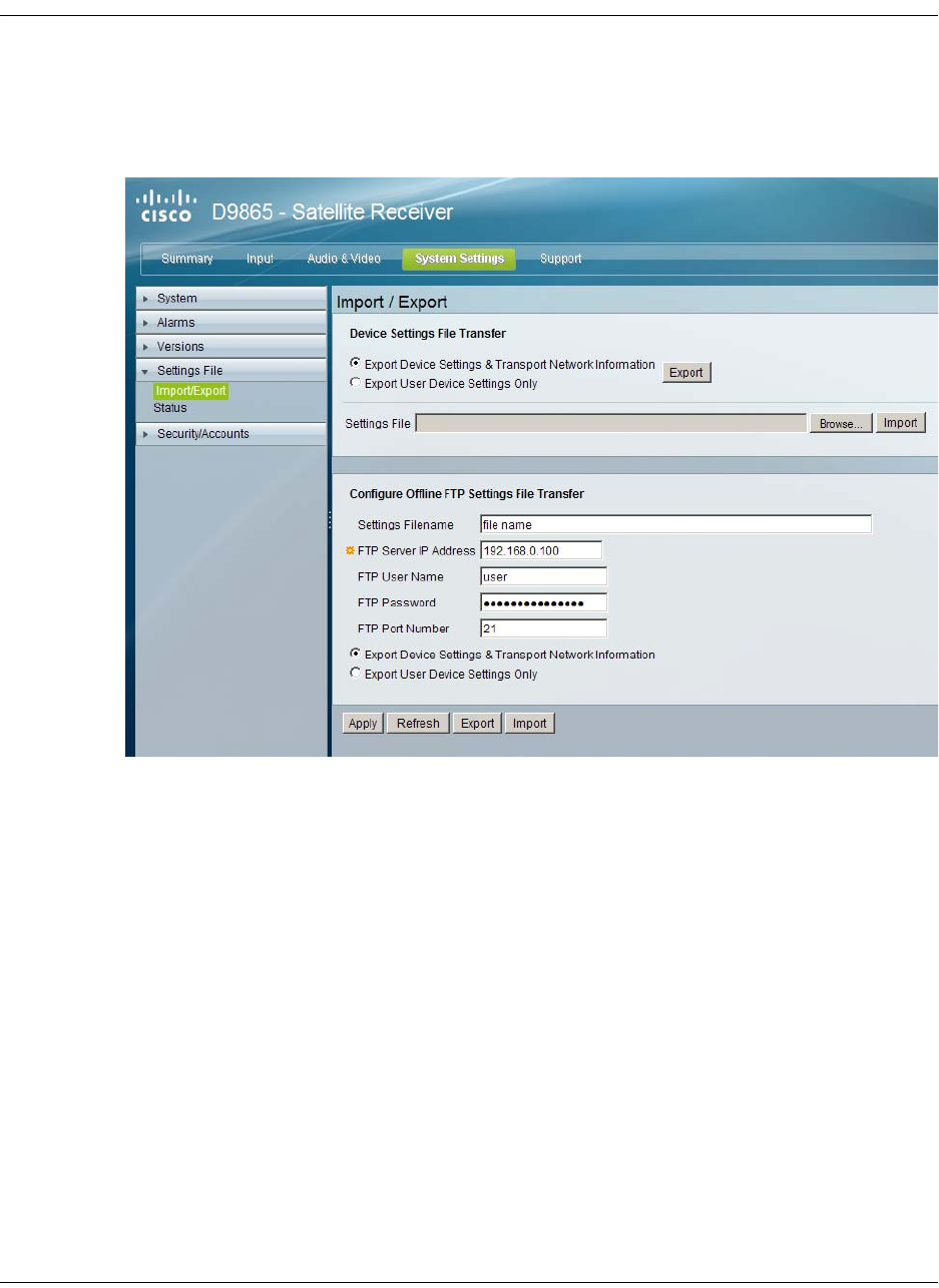
4035197 Rev C D9865 Satellite Receiver Installation and Operation Guide 5-59
Setting Up Import/Export Information
To Configure the Import/Export Information
Proceed as follows to configure the import/export information:
1. From the user interface of the D9865, click System Settings > Settings File >
Import/Export. The Import/Export page is displayed.
In the Device Settings File Transfer section, you can export and/or import device
settings and transport network information.
2. Select Export Device Settings & Transport Network Information and click
Export to download device settings and transport network information as a file
to the designated file folder.
3. Select Export User Device Settings only and click Export to download user
settings as a file to the designated file folder.
4. In the Settings File, click Browse. The Choose File dialog opens.
5. Navigate to the appropriate folder and select the file with a .bkp file extension
and click Open.

5-60 D9865 Satellite Receiver Installation and Operation Guide 4035197 Rev C
Setting Up Import/Export Information, Continued
The Configure Offline FTP Settings File Transfer section has backup and restore
controls.
6. Type the Settings Filename of the backup/restore file. You can enter up to 31
characters.
7. Set the FTP Server IP Address of the FTP server used to restore the backup/
restore file. The address is up to 12 characters in length (e.g. 171.300.100.200) and
in the range from 0 to 255.
8. Set the FTP User Name and FTP Password to access the FTP server.
Note: The FTP Password is not retained in the receiver. You must re-enter the
password before initiating the backup or restore operation.
9. Set the FTP Port Number of the FTP server used to store the backup/restore file.
You can enter a port number in the range from 1 to 65535.
10. Select Export Device Settings & Transport Network Information or Export
User Device Settings Only.
11. Click Export to save the settings to a backup file. Click Import to retrieve the last
backed up file.
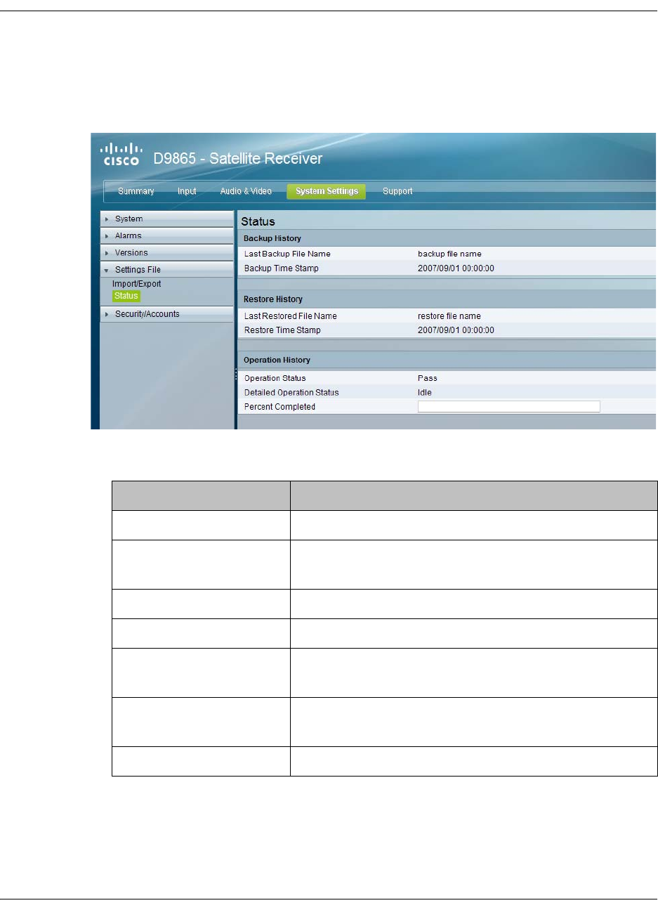
4035197 Rev C D9865 Satellite Receiver Installation and Operation Guide 5-61
Viewing the Backup/Restore History
To View the backup and restore Status Information
Proceed as follows to view the backup and restore Status page:
From the user interface of the D9865, click System Settings > Settings File > Status.
The Status page is displayed.
The following table shows the Backup History, Restore History, and Operation
History table information:
Status Description
Last Backup File Name Name of the file that was successfully exported.
Backup Timestamp Date and time of the last successful backup file
saved.
Last Restored File Name Name of the last file that was successfully restored.
Restore Time Stamp Date and time of the last successful restore.
Operation Status Status of the current backup operation (Inprogress,
Pass, or Fail).
Detailed Operation
Status
Detailed processing step for tracking backup
progress.
Percentage Completed Percentage of backup function completed.
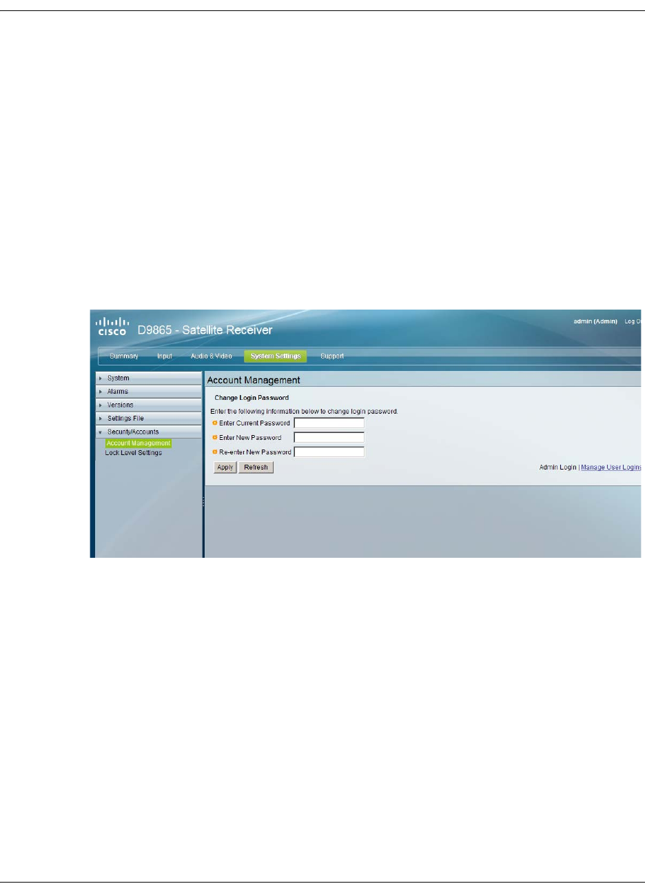
5-62 D9865 Satellite Receiver Installation and Operation Guide 4035197 Rev C
Managing D9865 Web GUI Accounts
You can define up to 10 usernames/passwords for login use via Web GUI session
on the D9865 Satellite Receiver.
When a user tries to login, the user is required to provide a username and a
password. The user is granted access only if this username/password pair exists in
the authentication table.
The default user is the “Admin User” and is granted special privileges. The Admin
user is allowed to add new users, delete users, change usernames and modify its
own password. All other users are only allowed to modify their own passwords.
To Configure the User Login Passwords
Proceed as follows to change the login password:
1. From the user interface of the D9865, click System Settings > Security/Accounts
> Account Management. The Account Management page is displayed.
2. In the Enter Current Password, type the current login password.
3. In the Enter New Password, type the new login password.
4. In the Re-enter New Password, type the new login password again to confirm.
Note: The Enter New Password and Re-enter New Password should be
identical. Each user, including the admin user, can modify only his own
password.
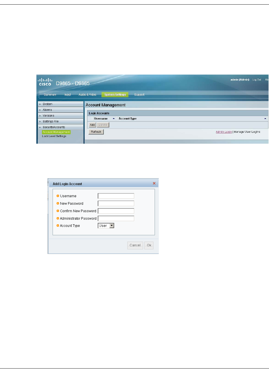
4035197 Rev C D9865 Satellite Receiver Installation and Operation Guide 5-63
Managing D9865 Web GUI Accounts, Continued
To Add a User Account
Note: This feature is available to a user with Admin privileges only.
Proceed as follows to manage user accounts:
1. From the user interface of the D9865, click System Settings > Security/Accounts
> Account Management. The Account Management page is displayed.
2. Click Manage User Logins. The Login Accounts page is displayed.
3. Click Add to create a new login account.
Note: You can create a maximum of 10 user accounts.
The Add Login Account window is displayed.
4. In the Username field, enter a user ID. The new username should not match any
of the usernames already defined in the Logins Accounts table.
5. In the New Password field, enter a password to assign the user ID. The
following are rules for creating a new password:
• It cannot contain any of the Username.
• It cannot contain any of the following strings: Cisco, sciatl, ocsic, italics, or any
string achieved by full or partial capitalization of letters.
• No letter is repeated more than three times in a row.
• Must contain a minimum of four characters.
6. Enter the new password again to confirm in the Confirm New Password field.
Note: The New Password and Confirm New Password should be identical.
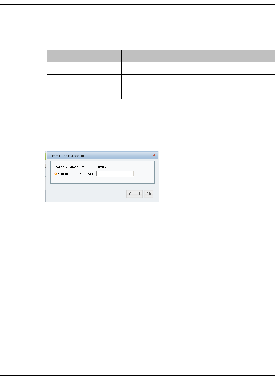
5-64 D9865 Satellite Receiver Installation and Operation Guide 4035197 Rev C
Managing D9865 Web GUI Accounts, Continued
7. In the Administrator Password field, enter your Administrator password used
to log on to the D9865 web GUI.
8. In the Account Type drop-down list, select User, Admin, or Guest. The
following table illustrates the different login types:
To delete a user account
Note: This feature is available to a user with Admin privileges only.
1. In the Account Management table, select the user you want to remove.
2. Click Delete. The Delete Login Account window is displayed.
3. Enter your Administrator Password to confirm the deletion.
4. Click OK. The selected user account is deleted.
Account Type Access
Guest View settings only.
User View and edit settings.
Admin View, edit settings, and add/delete user accounts.
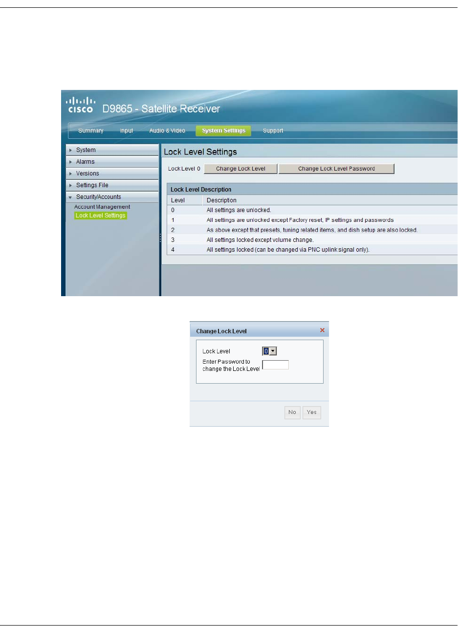
4035197 Rev C D9865 Satellite Receiver Installation and Operation Guide 5-65
Configuring Lock Level Settings
To Configure the Lock Level settings
Proceed as follows to configure the lock level settings:
1. From the user interface of the D9865, click System Settings > Security/Accounts
> Lock Level Settings. The Lock Level Settings page is displayed.
2. Click Change Lock Level and the Change Lock Level window is displayed.
3. Select the Lock Level which restricts access and prevents unauthorized changes
to the receiver settings (0, 1, 2, or 3). The default setting is 0.
Note: For details on the four lock levels, see D9865 Satellite Receiver Lock
Levels, on page C-2.
4. Enter the Password to change the lock level. The default password is 1234.
5. Click Yes.
If the incorrect lock level or password is entered, an error message appears at
the top of the page.
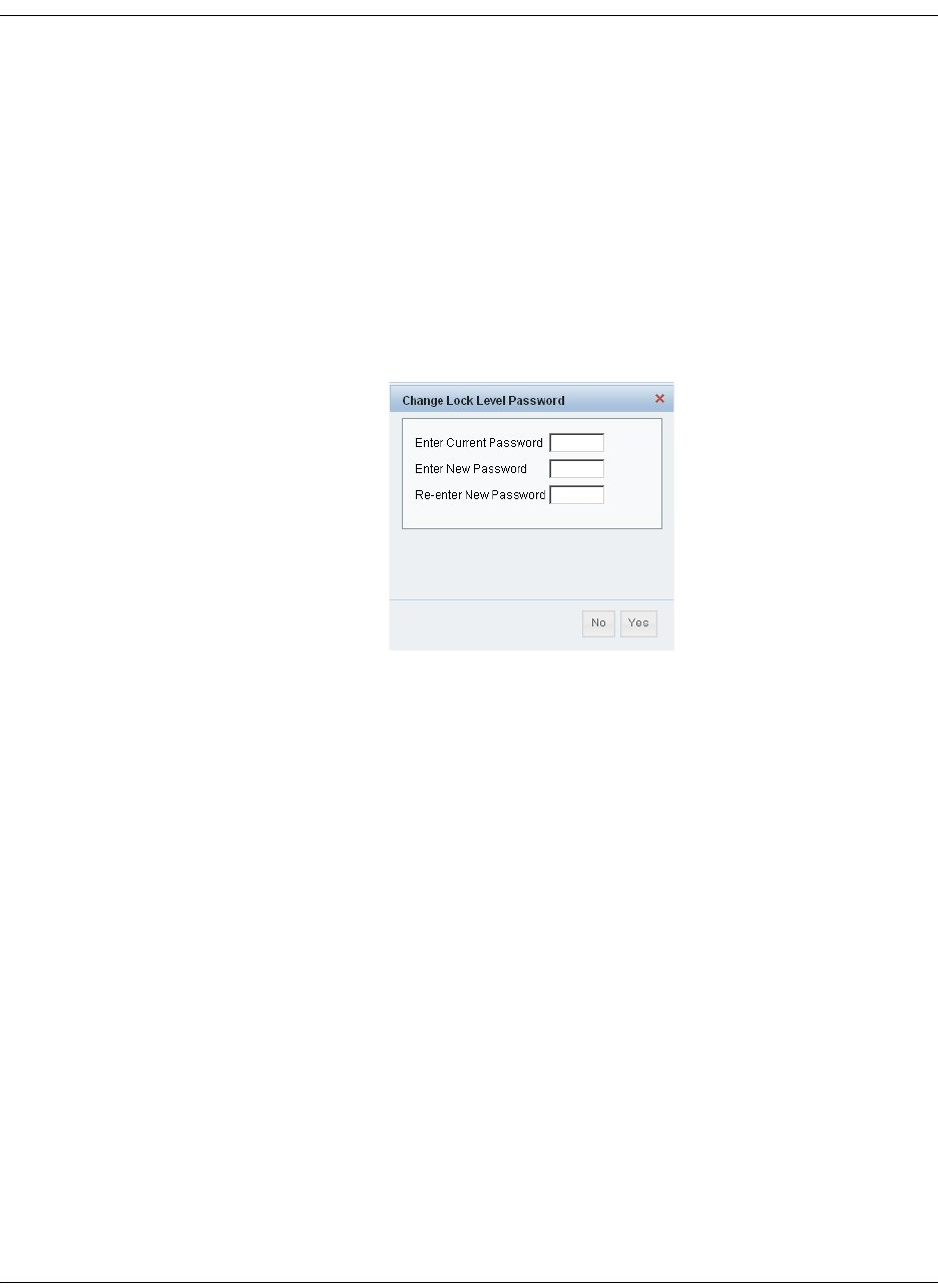
5-66 D9865 Satellite Receiver Installation and Operation Guide 4035197 Rev C
Configuring Lock Level Settings, Continued
Changing the Lock Level Password
A unique lock level password (4-digit password) protects the current receiver
settings against unauthorized changes. When changing the password, record and
keep this number in a secure location. The default password is 1234.
Important: Proceed with caution when changing the password as this operation
cannot be undone. If the password is lost or is unavailable, contact Cisco customer
support.
To change the lock level password:
1. In the Lock Level Settings page, click Change Lock Level Password. The
Change Lock Level Password window is displayed.
2. Enter the Current lock level Password.
3. In the Enter New Password field, enter the new password, any number from 0
to 9.
4. Re-enter the New Password and click Yes. A message appears informing you
that the password was changed successfully.
Note: If the password is lost or is unavailable, contact Cisco customer support.
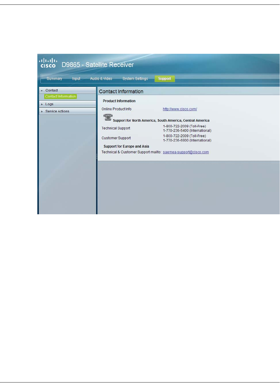
4035197 Rev C D9865 Satellite Receiver Installation and Operation Guide 5-67
Viewing Contact Information
To View Cisco Contact Information
Proceed as follows to view contact information:
From the user interface of the D9865, click Support > Contact. The Contact
Information page is displayed.
The Contact Information page displays all the Cisco customer support information.

5-68 D9865 Satellite Receiver Installation and Operation Guide 4035197 Rev C
Viewing Diagnostic Logs
To View the Diagnostic Log Messages
Proceed as follows to view the Diagnostic Log messages page:
From the user interface of the D9865, click Support > Logs > Diagnostic Logs. The
Diagnostic Logs page is displayed.
The Diagnostic Logs page displays all the system log messages with their dates and
times.
Click on the arrow next to Set Date and Time column to sort by date and time.
Click to sort by date and time.
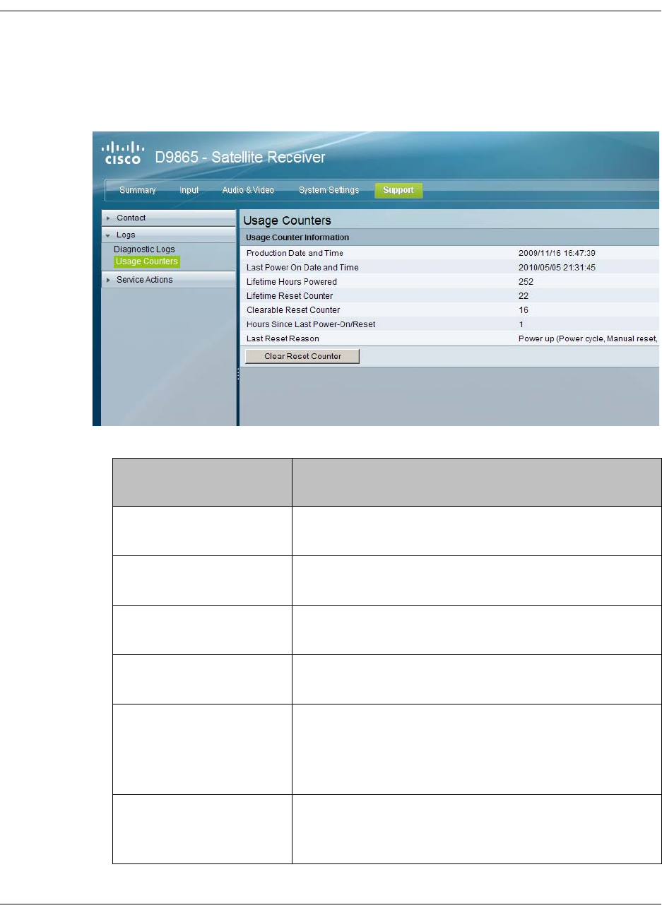
4035197 Rev C D9865 Satellite Receiver Installation and Operation Guide 5-69
Viewing the Usage Counters
To View the Device Usage Counters
Proceed as follows to view the usage counters:
From the user interface of the D9865, click Support > Logs > Usage Counters. The
Usage Counters page is displayed.
The following table describes the Usage Counter Information:
Device Status
Information
Description
Production Date & Time Displays the date and time when the receiver was
manufactured.
Last Power On Date and
Time
Displays the date and time when the receiver was
powered up.
Lifetime Hours Powered Displays the number of hours since the last power-
on.
Lifetime Reset Counter Displays the total number of times the receiver has
been restarted.
Clearable Reset Counter Displays the number of restarts since the last time
the restart counter was cleared.
To clear or reset the Clearable Reset Count, click
Clear.
Hours Since Last
Powered-On/Reset
Displays the total number of hours that the receiver
has been operating since the last power-on or
restart.

5-70 D9865 Satellite Receiver Installation and Operation Guide 4035197 Rev C
Click Clear Reset Counter to clear the Clearable Reset Counter field and it resets
the counter back to 0.
Last Reset Reason Displays the reason for the last restart, i.e., power
cycle or manual reset.
Device Status
Information
Description
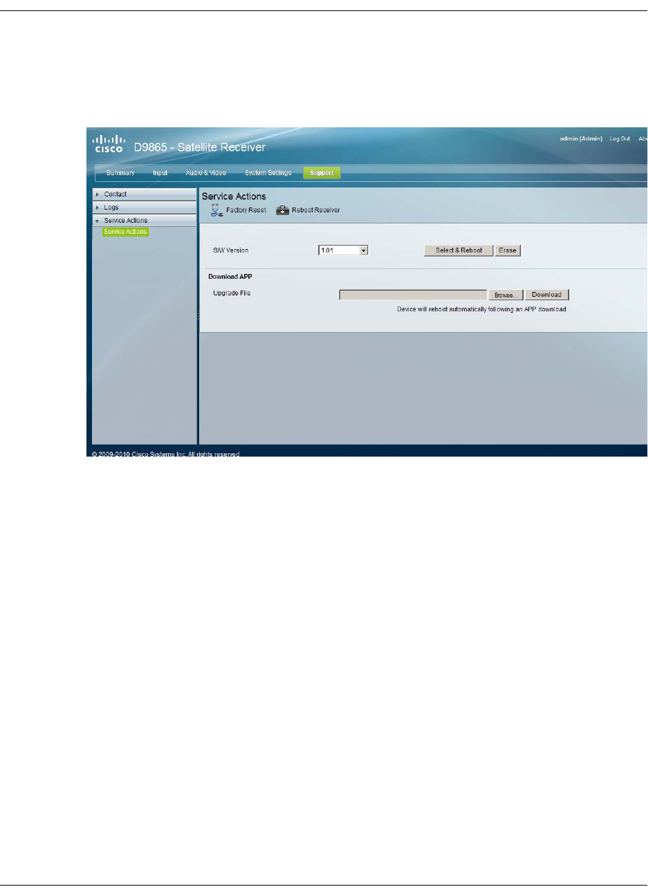
4035197 Rev C D9865 Satellite Receiver Installation and Operation Guide 5-71
Performing Service Actions
To Load a Software Version
Proceed as follows to load a software version:
1. From the user interface of the D9865, click Support > Service Actions. The
Service Actions page is displayed.
The S/W Version drop-down list allows you to select a different application version
application to load to your receiver. Click Select and Reboot to load the selected
application version and reboot the receiver.
Click Erase to remove the selected application version. You will be prompted to
continue or not. Press OK to continue the deletion.
Click Factory Reset to perform a reset of receiver settings back to the factory set
(default) values. A warning message prompts you to confirm the operation. Click
OK to continue or No to cancel the operation.
Click Reboot Receiver to reboot the receiver. You will be prompted to verify the
operation. Click Yes to reboot the receiver or No to cancel the operation.
To Change the Download Application
In the Download APP section, click Browse to select the new version of the D9865
Satellite Receiver’s software application. The Choose File dialog opens. Select the
upgrade file and click Open. Click Download to download the selected upgrade
file.

5-72 D9865 Satellite Receiver Installation and Operation Guide 4035197 Rev C

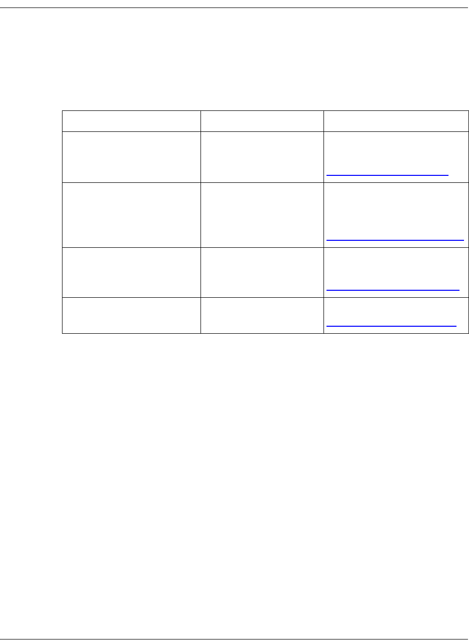
6-2 D9865 Satellite Receiver Installation and Operation Guide 4035197 Rev C
Product Support
Cisco provides its customers who have purchased support agreements with
telephone support from anywhere in the world. If you require technical telephone
assistance or product training support, or if you have any questions concerning
your Cisco product, you may contact the appropriate Customer Support Center
from those listed below. Charges may apply for customers without a current and
applicable product support agreement.
Customers who call a Customer Support Center are asked specific questions in
order to identify their needs. In this way, each call can be directed to the customer
support representative most experienced with their Cisco product. Customer
Support Centers also provide the following pre- and post-sales support services for
Cisco products.
Training Support
On and off-site training plus technical support services are available for purchase
for both equipment operators and system administrators.
Warranty and Post-Warranty Support
Warranty and post-warranty support services are available to help customers
return Cisco products for service or repair.
Customers Location Phone Number
Programmers and
Broadcasters
USA and Canada Toll-free: 1.888.949.4786
+1.770.236.4786
dmn_support@cisco.com
Telcos and Cable Service
Providers
Cisco Services Toll-free: 1.800.722.2009
Local: 678.277.1120 (press 2
at the prompt)
customer-service@cisco.com
All Customers Europe +32.56.445.155 or
+32.56.445.197
saemea-support@cisco.com
All Customers Asia +852.2588.4746
saapac-support@cisco.com

4035197 Rev C D9865 Satellite Receiver Installation and Operation Guide 6-3
Product Support, Continued
Customer Responsibility
When returning equipment, the customer is solely responsible for equipment
packaging and transportation costs to the factory.
At the customer's request, Cisco will make reasonable efforts to provide warranty
service at the customer's premises, provided that the customer pays current field
service rates plus direct travel and accommodation expenses.
In Case of Repair
If your product requires repair, perform the following steps:
1. Notify Cisco of the problem immediately, providing the model number and
serial number of the equipment plus details of the problem. Upon receipt of this
information, service information and shipping instructions will be provided.
2. Upon receipt of instructions, return the product by prepaid freight. Refer to the
section Returning Products for details.
In Case of a Fault
If your product requires repair, perform the following steps:
1. Notify Cisco of the problem immediately, providing the model number and
serial number of the equipment plus details of the problem. Upon receipt of this
information, service information and shipping instructions will be provided.
2. Upon receipt of instructions, return the product by prepaid freight. Refer to the
section Returning Products for details.

6-4 D9865 Satellite Receiver Installation and Operation Guide 4035197 Rev C
Returning Products
Introduction
You must have a return material authorization (RMA) number to return a product.
Contact the nearest customer service center and follow their instructions.
Returning a product to Cisco for repair includes the following steps:
• Obtaining a RMA number
• Obtaining a customer service center shipping address
• Packing and shipping the product
Obtaining an RMA Number and Shipping Address
You must have an RMA number to return products.
RMA numbers are valid for 60 days. If you already have a number, but it is older
than 60 days, you must contact a customer service representative to revalidate the
number. You can return the product after the RMA number is revalidated.
Follow these steps to obtain an RMA number and shipping address.
1. Contact a customer service representative to request a new RMA number or
revalidate an existing one.
2. Provide the following information to the customer service representative:
• Product name, model number, part number, serial number (if applicable)
• Quantity of products to return
• A reason for returning the product
• Your company name, contact, telephone number, email address, and fax
number
• Any service contract details
• Purchase order number of repair disposition authority, if available
Note: If you cannot provide a purchase order number:
• A proforma invoice listing all costs incurred will be sent to you at the
completion of product repair.
• Customer service must receive a purchase order number within 15 days after
you receive the proforma invoice.
• Products can accrue costs through damage or misuse, or if no problem is
found. Products incurring costs will not be returned to you without a valid
purchase order number.
3. The customer service representative issues the RMA number and provides the
shipping address.
Note: Absence of the RMA number may delay processing of product repair
and/or result in the equipment being returned unrepaired. Include the RMA
number in all correspondence.

4035197 Rev C D9865 Satellite Receiver Installation and Operation Guide 6-5
Returning Products, Continued
Packing and Shipping the Product
Follow these instructions to pack the product and ship it to Cisco.
1. Are the product's original container and packing material available?
•If yes, pack the product in the container using the packing material.
•If no, pack the product in a sturdy, corrugated box, and cushion it with
packing material.
Important:
• You are responsible for delivering the returned product to Cisco safely and
undamaged. Shipments damaged due to improper packaging may be refused
and returned to you at your expense.
• Do not return any power cords or accessories.
2. Write the RMA number on the outside of the container.
Note: Absence of the RMA number may delay processing of product repair
and/or result in the equipment being returned unrepaired. Include the RMA
number in all correspondence.
3. Ship the product to the address provided by the customer service
representative.
Note: Cisco does not accept freight collect. Be sure to prepay and insure all
shipments.

6-6 D9865 Satellite Receiver Installation and Operation Guide 4035197 Rev C

4035197 Rev C D9865 Satellite Receiver Installation and Operation Guide 7-1
Chapter 7
Service and Maintenance
Overview
Introduction
This chapter provides additional information on the alarms and warnings of the
D9865 Satellite Receiver. It also provides troubleshooting tips.
In This Chapter
This chapter contains the following topics.
Topic See Page
Messages 7-2
Troubleshooting 7-19

7-2 D9865 Satellite Receiver Installation and Operation Guide 4035197 Rev C
Messages
General
The status of the D9865 receiver and its immediate surroundings is reported to the
receiver in the form of messages and alarms. You can enable or disable messages in
the Alarms & Warnings advanced settings.
D9865 Receiver Message List
The following table shows a list of the available messages and their default alarm
status. The Set Messages and Clear Messages are displayed in the Warning History
when the messages are set or cleared respectively.
Alarms
Alarm Message
Type
Message Cause/Remedy Description Severity
Signal Status Set Signal is lost Cause: Loss of RF
signal. Loss of RF
lock. Loss of
Transport data.
Invalid frequency or
other tuning
parameters.
Remedy: Check
cables. Check tuning
parameters.
Loss of signal Minor
RF Signal - No
Content
RF Tuner locked,
but no TS
content.
Tuning Parameters
Invalid
One of the
tuning
parameters is
invalid
Clear Signal is locked Signal OK
Tuning Parameters
Valid
Tuning
parameters are
valid

4035197 Rev C D9865 Satellite Receiver Installation and Operation Guide 7-3
Program Not
Auth
Set Channel is not
authorized
Cause: The channel is
unauthorized for the
current program.
Remedy: Contact
your (uplink) service
provider to
determine whether
you are authorized to
receive the current
program.
Program
unauthorized
because the tier
bits do not
match.
Minor
Channel requires an
authorization key
Program is
unauthorized
because the unit
does not have an
authorization
key.
Channel is blacked
out
Program is
unauthorized
because at a
minimum, it
needs to match
one blackout
code.
Channel uses an
unknown CA system
Cause: Conditional
access not supported.
Remedy: Contact
your (uplink) service
provider to
determine whether
you are authorized to
receive the current
program at this time.
Non-SA
conditional
access system.
Channel
authorization refused
ISE UA does not
match factory
configuration.
Channel requires an
IRD with CA support
Conditional
access is not
supported.
Channel requires the
PE to have an ISE
Cause: Hardware
issue.
Remedy: Clear
alarms, reset unit,
and notify customer
service if problem
persists.
In-board security
element is not
present.
Clear Fault Reset
Channel is
authorized
Alarm Message
Type
Message Cause/Remedy Description Severity

7-4 D9865 Satellite Receiver Installation and Operation Guide 4035197 Rev C
CAM/CI Slot
Status
Set Initialization Fail Cause: CAM is
damaged or not fully
inserted
Remedy: Re-insert
the CAM.
Initialization of
CAM failed.
Minor
Clear CAM Operation OK
CI Status Set Program Not
Descrambled
Cause: Hardware
issue, CAM software
crash or you don’t
have subscription
rights for the smart
card.
Remedy: Reinsert the
CAM and/or check
your rights for the
smart card.
All elementary
streams for this
service selected
for descrambling
were not
descrambled by
the CAM.
Minor
Clear Descrambling OK
Shutdown Event Set DL APP REBOOT Cause: User request
requires reboot or
internal system error.
Remedy: If it is an
internal system error
fault, clear alarms,
reset the unit, notify
customer service if
the problem persists.
New application
downloaded,
system requires
reboot.
Major
I2C Failure Internal system
error.
User requested APP
change
Runnable
application
change requires
reboot.
User requested
factory reset
Factory reset
requires reboot.
User requested
reboot
User reboot
request.
PRODUCTION -
Protect Flash
Reboot after
production
tables removed.
WDOG requesting
shutdown shell
command
User entered
command
requesting
shutdown
WDOG shutdown
shell command
Alarm Message
Type
Message Cause/Remedy Description Severity

4035197 Rev C D9865 Satellite Receiver Installation and Operation Guide 7-5
osal_SetDataForAllTa
sks
Cause: Possible
software issue.
Remedy: Clear
alarms, reset unit,
notify customer
service if problem
persists.
Application
initialization
error.
aw_LoadFaultList
osal_Init
NVS FLASH
mounted
DB_Table_Cl::popula
teNvsRecords
STAPI_Init
DB_Array32_Cl init
failed
DB_FlagArray32_Cl
init failed
Wrong DB Item
detected: item =
AAA, table = BBB
DB_Item_Cl::addItem
() failed
Memory allocation
error on DB table
construction
DB_Table_Cl::addTa
ble() failed
DB_Table_Cl::addIte
m() failed: too many
DB Items
DBT Init Failed: AAA
Framework
Registration Error
7109 exception! Code
= X, Address = Y,
Task = Z
Memory Error: AAA,
Phase X
Product Control table
creation failed
Alarm Message
Type
Message Cause/Remedy Description Severity

7-6 D9865 Satellite Receiver Installation and Operation Guide 4035197 Rev C
Product Config table
creation failed
MAC Address table
creation failed
HW Data table
creation failed
PCB table creation
failed
FPGA Settings table
creation failed
Prod Aud Tbl
creation failed
Prod FE Tbl creation
failed
Product Version table
creation failed
Product User
Address table
creation failed
Product Reference
Number table
creation failed
Time Control object
creation failed
Wrong UIC Item
detected: item =
AAA, table BBB
Alarm Message
Type
Message Cause/Remedy Description Severity

4035197 Rev C D9865 Satellite Receiver Installation and Operation Guide 7-7
Memory allocation
error on UIC table
construction
Error adding UIC
table(AAA)
UD -
ud_init_phase_4()
FAILED to allocate
memory from System
Partition
UD -
ud_init_phase_4()
FAILED to create
partition
FW: Memory or List
Full
Internal system
error.
Framework
Registration Error
WDOG task:
watchdog aud st
wdog has expired
Software
detected an error
in operation.
WDOG task:
watchdog MC OCM
has expired
WDOG task:
watchdog MC
SCRIPT has expired
WDOG task:
watchdog Secondary
WD has expired
Alarm Message
Type
Message Cause/Remedy Description Severity

7-8 D9865 Satellite Receiver Installation and Operation Guide 4035197 Rev C
System Startup Set System Startup Cause: Restarted the
D9865 Satellite
Receiver.
Remedy: None. It
will automatically
reset after 1 second.
Indicates the
D9865 has
restarted.
Minor
Clear Backup/Restore
System Startup
Cause: Backup/
Restore updated
settings during a
system startup.
Remedy: None. It
will automatically
reset after 1 second.
LMI setup Set LMI SDRAM exhaust
test failed
Cause: Hardware
issue.
Remedy: Clear
alarms, reset the unit,
and notify customer
service if the problem
persists.
DDR RAM on
LMI bus not
working.
Major
Clear LMI Video SDRAM
exhaust test passed
DDR RAM on
LMI bus OK.
Param Storage Set DB NVS flushing
ignored
Cause: Hardware
issue.
Remedy: Clear
alarms, reset the unit,
and notify customer
service if the problem
persists.
Non-volatile
storage system
failed to update
fully.
Major
RAM flush to NVS
failed
DB Factory Reset
failed
Non-volatile
storage system
failed during
factory reset.
Clear DB flushing
completed
Successful NVS
update.
DB Factory Reset
completed
Successful
action.
Alarm Message
Type
Message Cause/Remedy Description Severity

4035197 Rev C D9865 Satellite Receiver Installation and Operation Guide 7-9
Flash Storage Set RECORD: init failed Cause: Hardware
issue.
Remedy: Clear
alarms, reset the unit,
and notify customer
service if the problem
persists.
Non-volatile
storage system
corrupted.
Possible loss of
configuration
Major
RECORD
MANAGER: Record
contents check error,
erasing all
NVS Corruption,
loss of
configuration
data
RECORD: sector
setup check error,
erasing sector
NVS Corruption,
loss of sector
data
Clear RECORD: init done
LNB PS Set LNBPS: No Load Cause: Hardware or
wiring issue.
Remedy: Clear
alarms, check LNB
and wiring, and
notify customer
service if the problem
persists.
LNB power
overload
Minor
LNBPS: Over
Temperature
LNBPS: Over Loaded
LNBPS: Short Circuit
Clear LNBPS: Normal LNB power OK
LNBPS: Disabled
LNBPS: Off
DiSEqC HW
Fault
Set DiSEqC Hardware
Fault
Cause: Hardware
issue.
Remedy: Clear
alarms, check LNB
and wiring, and
notify customer
service if the problem
persists.
Ensure LNB power is
on (even if using
external LNB power)
and DiSEqC is
enabled.
Unable to send
DiSEqC
commands to
external
equipment.
Minor
Clear Automatically
cleared after a
few seconds.
Alarm Message
Type
Message Cause/Remedy Description Severity

7-10 D9865 Satellite Receiver Installation and Operation Guide 4035197 Rev C
Signal Quality Set Audio Muted due to
RF noise
Cause: RF Signal
quality is poor due to
interference or signal
level issues.
Remedy: Check RF
settings, re-aim dish,
and add signal
amplifier.
Signal is locked
but BER is
beyond Audio
muting
threshold.
Minor
Unstable RF Signal Signal lock
status is toggling
frequently.
Poor Quality RF
Signal
Signal is locked
but BER is
beyond muting
threshold.
Clear Signal Quality Fault
Cleared
Audio Unmuted
Transport
Processing
Set PTI lockup Cause: Possible
software issue.
Remedy: Clear
alarms, reset unit,
and notify customer
service if problem
persists
Programmable
transport input
module stopped
processing any
data packet.
Minor
Clear PTI running
DL Write/Erase
Fault
APP Flash Write
Failed
Cause: Downloaded
application CRC
check failed or failed
to write application
to flash.
Remedy: Fault will
reset in 30 seconds.
Notify customer
service if problem
persists.
APP Flash Write
Failed.
Major
Alarm Message
Type
Message Cause/Remedy Description Severity

4035197 Rev C D9865 Satellite Receiver Installation and Operation Guide 7-11
Boot Host Set KB not accessible Cause: Hardware
issue
Remedy: Clear
alarms, reset unit,
and notify customer
service if the problem
persists.
KB is not
detected by Boot
code.
Major
FLASH Not Found Flash memory
not detected.
BOOT Invalid Boot SW cannot
be read from
memory
correctly.
APP Invalid Application SW
cannot be read
from memory
correctly.
Clear BOOT passed
Alarm Message
Type
Message Cause/Remedy Description Severity

7-12 D9865 Satellite Receiver Installation and Operation Guide 4035197 Rev C
MPE alarm Set Data lost, transport
error
Cause: Transport
error indicator is set
in the transport
stream.
Remedy: Verify
uplink is in good
condition.
Transport error
detected, MPE
data may be lost.
Major
Data lost, CRC error Cause: CRC error
detected in MPE
stream.
Remedy: Verify
uplink is in good
condition.
CRC error
detected in MPE
stream, data is
lost.
Data lost, CC error Cause: CC error
detected in MPE
stream.
Remedy: Verify
uplink is in good
condition.
CC error
detected in MPE
stream, data is
lost.
Data lost, buffer
overflow
Cause: Buffer
overflow detected in
MPE stream.
Remedy: Reduce
MPE rate.
Buffer overflow
detected in MPE
stream, data is
lost.
Data lost, bad
sections
Cause: Bad section
data detected in MPE
stream, due to
original data or
overflow issue.
Remedy: Verify
uplink is in good
condition and/or
reduce MPE rate.
Bad sections
detected while
processing MPE
data, data is lost.
Data lost, MPE
capacity exceeded
Cause: Bit rate
controller dropping
data due to CPU load
limitations.
Remedy: Reduce
MPE rate.
Decoder
exceeded safe
CPU load for
MPE processing,
MPE data is lost.
Alarm Message
Type
Message Cause/Remedy Description Severity

4035197 Rev C D9865 Satellite Receiver Installation and Operation Guide 7-13
MPE capacity is
reached.
Cause: Unit is busy
processing or
handling other
services.
Remedy: Reduce
service load.
Decoder reached
the limit of safe
CPU load for
MPE processing.
LECTimeout Set LEC Table Missing/
timeout: channels
currently unavailable
Cause: LEC table
missing in the signal.
Remedy: Verify
uplink is sending
LEC tables.
LEC table
missing or not
received
Major
Reset LEC received
Alarm Message
Type
Message Cause/Remedy Description Severity

7-14 D9865 Satellite Receiver Installation and Operation Guide 4035197 Rev C
Messages, Continued
Warnings
The following table shows a list of the available messages and their default warning
status.
Warning Message
Type
Message Cause/Remedy Description
Transport Error Set Continuity Count
Error
Cause: Possible uplink or
signal issue.
Remedy: Clear warnings,
reset the unit, and notify
customer service if the
problem persists.
Transport packet
continuity count
jumped. Possible
packet loss.
Buffer Overflow The transport stream
is faster than the
maximum buffer or
the decode engines
are having difficulty
handling the data
sent to them.
Transport Error
Indicator
Transport packets are
marked as "errored"
upstream of the
decoder.
Clear Continuity Count
Error Cleared
Trap expires after 30
seconds.
Buffer Overflow
Cleared
Transport Error
Indicator Cleared
Video Format
Mismatch
Set Video format
mismatch
Video Format
Mismatch.
Clear Video format match
VBI Data Set 2nd VBI PID attempt
to write same line
Cause: Uplink
configuration issue.
Remedy: Contact uplink to
verify expected VBI
settings.
Conflicting VBI data
on second VBI PID.
Clear Line Collision
Cleared

4035197 Rev C D9865 Satellite Receiver Installation and Operation Guide 7-15
TDT timeout Set tdt timed out Cause: Uplink is not
sending or is sending
intermittently.
Remedy: Clear warning. If
the problem persists,
determine if uplink is
sending the current SI
information table. Disable
the warning if not using the
table.
Time Date Table was
never received.
tdt is lost No longer receiving
Time Date.
Clear tdt fault cleared
SDT timeout Set sdt # timed out Cause: Uplink is not
sending or is sending
intermittently.
Remedy: Clear warning. If
the problem persists,
determine if uplink is
sending the current SI
information table. Disable
the warning if not using the
table.
Service Description
Table was never
received.
sdt # is lost No longer receiving
Service Description.
Clear sdt fault cleared
PMT timeout Set pmt # timed out Cause: Uplink is not
sending or is sending
intermittently.
Remedy: Clear warning. If
the problem persists,
determine if uplink is
sending the current SI
information table. Disable
the warning if not using the
table.
Program Mapping
Table was never
received.
pmt # is lost No longer receiving
Program Mapping
Table.
Clear pmt fault cleared
PAT timeout Set pat # timed out Cause: Uplink is not
sending or is sending
intermittently.
Remedy: Clear warning. If
the problem persists,
determine if uplink is
sending the current SI
information table. Disable
the warning if not using the
table.
Program Association
Table was never
received.
pat # is lost No longer receiving
Program Association
Table.
Clear pat fault cleared
Warning Message
Type
Message Cause/Remedy Description

7-16 D9865 Satellite Receiver Installation and Operation Guide 4035197 Rev C
NIT timeout Set nit timed out Cause: Uplink is not
sending or is sending
intermittently.
Remedy: Clear warning. If
the problem persists,
determine if uplink is
sending the current SI
information table. Disable
the warning if not using the
table.
Network Information
Table was never
received.
nit is lost No longer receiving
Network Information
Table.
Clear nit fault cleared
CAT timeout Set cat timed out Cause: Uplink is not
sending or is sending
intermittently.
Remedy: Clear warning. If
the problem persists,
determine if uplink is
sending the current SI
information table. Disable
the warning if not using the
table.
Conditional Access
Table was never
received.
cat is lost No longer receiving
Conditional Access
Table.
Clear cat fault cleared
ECT timeout Set ect timed out Cause: Uplink is not
sending or is sending
intermittently.
Remedy: Clear warning. If
the problem persists,
determine if uplink is
sending the current SI
information table. Disable
the warning if not using the
table.
Event Control Table
was never received.
ect is lost No longer receiving
Event Control Table.
Reset ect fault cleared
Memory Usage Host Set Excessive (stack/
partition) memory
usage
Cause: Possible software
issue.
Remedy: Clear warnings,
reset the unit, and notify
customer service if the
problem persists.
SW exceeding
allowable memory
usage.
Clear Normal (stack/
partition) memory
usage
MPE near capacity Set Approaching current
capacity
Cause: Unit is busy
processing or handling
other services.
Remedy: Reduce or stop
MPE service content.
Decoder approaching
limit of safe CPU load
for MPE processing.
Warning Message
Type
Message Cause/Remedy Description

4035197 Rev C D9865 Satellite Receiver Installation and Operation Guide 7-17
Ethernet MAC
Failure
Set MAC configuration
failed
Cause: Possible hardware
issue.
Remedy: Clear warnings,
reset the unit, and notify
customer service if problem
persists.
Errors like Fatal Bus
Error.
Clear Failure cleared
Ethernet PHY
Failure
Set Marvel switch
configuration failed
Cause: Possible hardware
issue.
Remedy: Clear warnings,
reset the unit, and notify
customer service if the
problem persists.
Related to MII
register read/write
failures.
Clear PHY failure
monitoring reset
Ethernet Port 1 or
Ethernet Port 2
Set ETH Port 1 or 2 Link
Down
Cause: Ethernet port 1 or 2
is not connected.
Remedy: Connect Ethernet
port 1 or 2.
Ethernet port 1 or 2 is
not connected.
Reset ETH Port 1 or 2 Link
Up
FW: Resource Use
PRI
Set Memory or List Near
Full
Cause: Possible software
issue.
Remedy: Clear warnings,
reset the unit, and notify
customer service if the
problem persists.
Software exceeding
allowable usage of
internal constructs.
Clear
Backup Operation
State
Set Backup Active Backup operation
started.
Clear Backup Complete Backup operation
complete.
Backup Failure
Reason
Set Internal Error Cause: Possible software
issue.
Remedy: Check FTP
configuration, reset unit,
and notify customer service
if problem persists.
Software error
occurred.
FTP Failed FTP failed.
Clear Auto reset after
timeout
Warning
automatically clears
in 30 seconds.
Restore Failure
Reason
Set Not Accepted Cause: Possible software
issue.
Remedy: Check FTP
configuration, reset unit,
and notify customer service
if problem persists.
Software error
occurred.
Bad Content
FTP Failed FTP failed.
Clear Auto reset after
timeout
Warning
automatically clears
in 30 seconds.
Warning Message
Type
Message Cause/Remedy Description

7-18 D9865 Satellite Receiver Installation and Operation Guide 4035197 Rev C
HDMI:Not an Auth
Device
Set HDCP authentication
failed
Cause: HDMI monitor is
not authorized to receive
HDMI content or it does
not support HDCP.
Remedy: Disconnect HDMI
monitor to restore video
decode or use an HDMI
monitor that properly
supports HDCP.
HDMI monitor does
not contain valid
HDCP keys. Video
decode is disabled.
Receiver not HDCP
capable
HDMI monitor does
not support HDCP.
Video decode is
disabled.
Clear HDCP
Authentication
Process Not Started
HDMI monitor is not
connected.
Connect an HDMI or
DVI capable monitor,
if desired.
HDCP authentication
success
HDMI monitor is
connected and
authorized to receive
HDMI content.
TV-Out Settings
Problem
Set Invalid configuration
data
Cause: Incorrect video
setup settings.
Remedy: Check the video
setup settings: TV Channel
Number and SD Video
Output format. For PAL
device, use channel 21
through 69 and SD Format
PAL-x. For NTSC device,
use channel 3 or 4 and SD
Format NTSC or NTSC-J.
Notify customer service if
problem persists.
Invalid TV-Out
configuration data
provided.
Clear Valid configuration
data
Valid TV-Out
configuration data
provided.
Warning Message
Type
Message Cause/Remedy Description

4035197 Rev C D9865 Satellite Receiver Installation and Operation Guide 7-19
Troubleshooting
General
If you experience any problems operating your satellite receiver, the following table
may help you resolve your problem.
Problem Cause Remedy
Blank screen (TV
switched on)
• Normal operation if
receiver is not on (power
switch on back panel).
• Press the Display button
on the receiver front
panel or remote control.
Scrambled channel
(not decoded)
• Subscriber services may
not be authorized for the
channel.
•Check that your
subscriber services are
currently authorized
(contact your service
provider).
Cannot access a
password protected
on-screen option
•You have entered an
incorrect password or the
password has been
changed.
• Check that you are using
the correct password. If
the password is lost or
unavailable, contact your
local service provider.
Remote Control not
operating properly
• The remote control may
be defective, or the
batteries are incorrectly
installed, or require
replacement.
• Replace or correctly
install the remote control
batteries.
Program Not
Authorized message is
displayed
• Subscriber services are
not authorized for
selected channel.
•Check that your
subscriber services are
authorized by viewing
signal status on the Dish
Setup menu (or contact
your service provider).
Authorization Key Not
Received message is
displayed
• Subscriber services are
not authorized due to
authorization key not
being received.
• Same as above.
No signal • Installation or signal
problem.
• Check connections to
receiver, dish alignment
and/or tuning setup.
Blank (black) screen is
displayed after exiting
to video from menus
• Channel 0 is displayed
after exiting to video
following changes made
to the current receiver
setup.
• Press CH+ or CH- on
remote control to display
channels.

7-20 D9865 Satellite Receiver Installation and Operation Guide 4035197 Rev C
Poor reception • Receiver is not properly
set up or connected to
receive satellite signal.
• Possible station trouble.
Signal source for one or
more (or all) channels is
temporarily affected by
technical transmission
problems or a temporary
solar disturbance.
• Satellite dish may not be
properly installed or is
not accurately aimed at
satellite signal.
• Check the connections to
and from satellite
antenna LNB, television
antenna, and all video
and audio cables (see
Quick Setup
Instructions, page 1-2).
• Check another channel to
compare signal
reception.
• Check that a maximum
Signal Level is achieved
or displayed when
aligning the dish.
No picture or sound • You have not turned
your receiver on or the
receiver is not properly
connected to the AC
power.
• Your antenna, video
and/or audio cables may
be faulty or not properly
connected.
• Possible station trouble.
The signal source for one
or more channels is
temporarily affected by
transmission problems or
due to a temporary solar
disturbance.
• Press the Display button
on the receiver front
panel or remote control.
• Check that the receiver is
properly connected to
the AC power.
• Check the connections to
the satellite antenna
LNB, television antenna,
and all video and audio
cables.
• Check another channel to
compare signal
reception.
Problem Cause Remedy

4035197 Rev C D9865 Satellite Receiver Installation and Operation Guide 7-21
No sound •The sound has been
muted.
• Audio cable may be
faulty or not properly
connected.
• Possible station trouble.
The signal source for one
or more channels is
temporarily affected by
transmission problems or
due to a temporary solar
disturbance.
• Digital Audio setting is
not configured properly.
• Same as above.
• Check that the volume is
not muted by pressing
the VOL+ or VOL-
button on the remote
control.
• Check another channel to
compare signal
reception.
•Check the Digital Audio
setting in the Audio
Setup screen. For
example, if it is set to
Dolby Digital, ensure
that your system
supports compressed
audio.
Poor picture • Same as above.
• Check another channel to
compare signal
reception.
Problem Cause Remedy

7-22 D9865 Satellite Receiver Installation and Operation Guide 4035197 Rev C
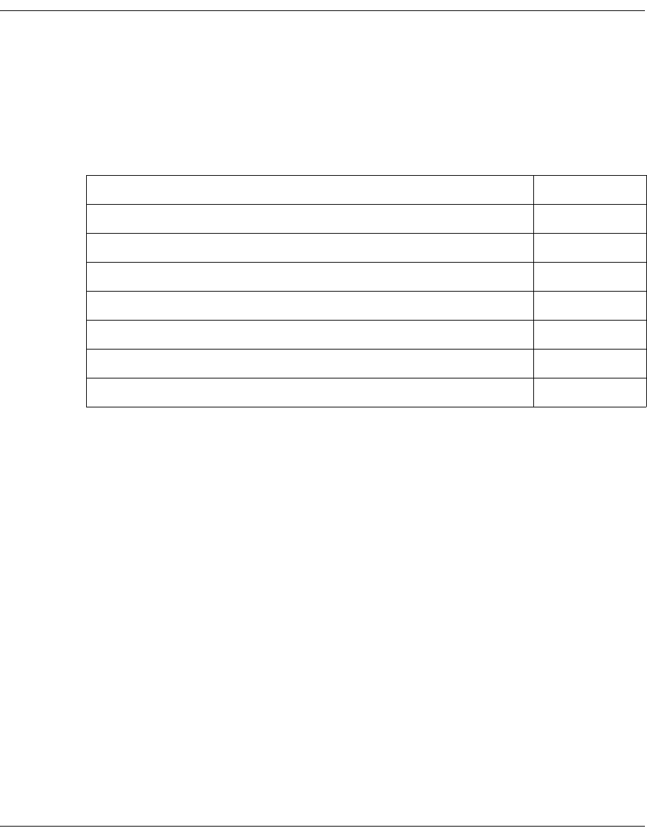
4035197 Rev C D9865 Satellite Receiver Installation and Operation Guide A-1
Appendix A
Technical Specifications
Overview
Introduction
This appendix contains the technical specifications for the D9865 Satellite Receiver.
Note: The technical specifications are subject to change without prior notice.
In This Appendix
This appendix contains the following topics.
Topic See Page
Receiver Specifications A-2
LNB Requirements A-3
DVB-S Eb/No (C/N) Ratio A-4
DVB-S2 Error Rate Performance ES/No (C/N) Ratio A-5
Video Output A-6
Audio Outputs A-7
Power A-8

A-2 D9865 Satellite Receiver Installation and Operation Guide 4035197 Rev C
Receiver Specifications
General
Tuner
Parameter Specification
System MPEG-2/DVB Compatible
EN300 421, EN 300468, H.264
Demodulation DVB-S QPSK, DVB-S2 QPSK and 8PSK
Number of RF Inputs 1
Parameter Specification
Number of RF Inputs 1
Input Level -25 dBm to -65 dBm per carrier
Frequency Range 950 MHz to 2150 MHz
Symbol Rate Range DVB-S: 1.0 to 45 MS/s
DVB-S2: 1.0 to 31 MS/s
Satellites C-band and Ku-band
Receiver Spectrum Sense Normal and Inverted
Input Impedance 75 Ω
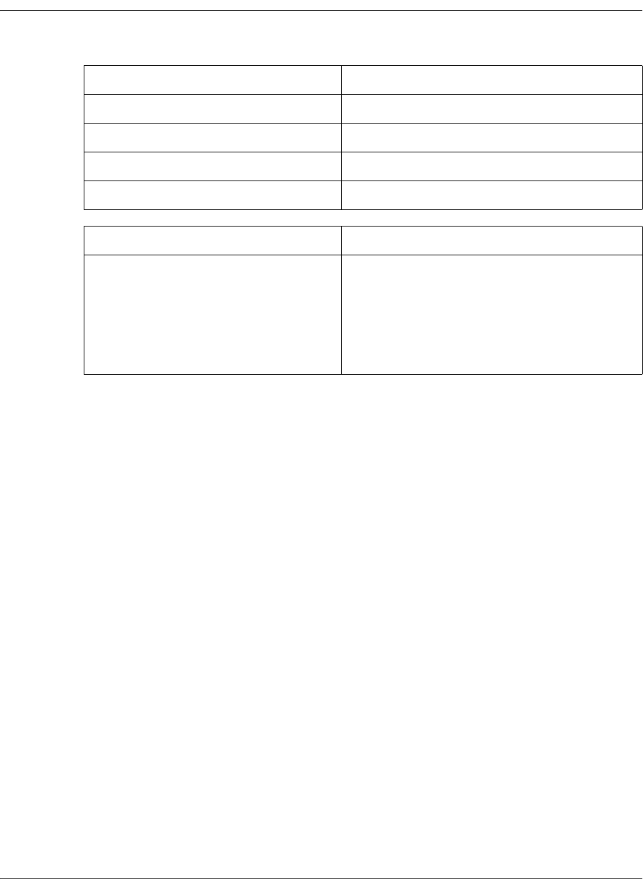
4035197 Rev C D9865 Satellite Receiver Installation and Operation Guide A-3
LNB Requirements
DVB-S and DVB-S2
Symbol Rate Stability
1 to 2.99 MS/s ≤ ± 0.125 MHz
3 to 5.99 MS/s ≤ ± 1.00 MHz
6 to 11.99 MS/s ≤ ± 3.00 MHz
12 to 45 MS/s ≤ ± 5.00 MHz
Parameter Specification
LNB Phase Noise Requirement -28 dBc/Hz at δF = 100 Hz
-53 dBc/Hz at δF = 1 kHz
-76 dBc/Hz at δF = 10 kHz
-93 dBc/Hz at δF = 100 kHz
-106 dBc/Hz at δF = 1 MHz
-117 dBc/Hz at δF = 10 MHz
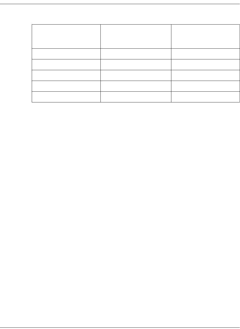
A-4 D9865 Satellite Receiver Installation and Operation Guide 4035197 Rev C
DVB-S Eb/No (C/N) Ratio
DVB-S Eb/No (C/N) Ratio
Note: The D9865 receiver displays the C/N Ratio.
C/N = Eb/No + 10 log (2 x FEC X 188/204).
Convolutional FEC Rate Eb/No Ratio (dB) in
Linear Channel and IF
Loop configuration
C/N at DVB Threshold
(BW = Symbol Rate)
1/2 4.5 4.1
2/3 5.0 5.9
3/4 5.5 6.9
5/6 6.0 7.9
7/8 6.4 8.5
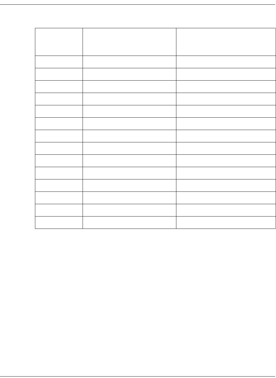
4035197 Rev C D9865 Satellite Receiver Installation and Operation Guide A-5
DVB-S2 Error Rate Performance ES/No (C/N) Ratio
DVB-S2 Error Rate Performance Es/No (C/N) Ratio
Note: “Typical performance” was measured with Pilots On. Pilots On is highly
recommended as the performance values typically degrade up to 0.9 dB with Pilots
Off. Pilots On must be used for 8PSK 3/5, 8PSK 2/3 and 8PSK 3/4.
Mode Simulated Es/No (dB) for FEC
Frame length = 64,800
Typical Performance (dB) in
Linear Channel and IF Loop
Configuration
QPSK 1/2 1.00 1.2
QPSK 3/5 2.23 2.4
QPSK 2/3 3.10 3.2
QPSK 3/4 4.03 4.2
QPSK 4/5 4.68 4.8
QPSK 5/6 5.18 5.3
QPSK 8/9 6.20 6.4
QPSK 9/10 6.42 6.6
8PSK 3/5 5.50 5.8
8PSK 2/3 6.62 6.8
8PSK 3/4 7.91 8.1
8PSK 5/6 9.35 9.6
8PSK 8/9 10.69 10.9
8PSK 9/10 10.98 11.3

A-6 D9865 Satellite Receiver Installation and Operation Guide 4035197 Rev C
Video Output
Analog Video Output
Digital Audio/Video Output (D9865H and D9865D only)
HD Analog Video Output (D9865H and D9865D only)
Parameter Specification
Number of channels 1
Connector Type RCA
Video Compression Type MPEG-2 4:2:0
MPEG-4 4:2:0
Level 1.0V pp ± 10%
Video Standard NTSC & PAL B/G/I/D/M/N/J, supports
HD downconversion
Parameter Specification
Number of Outputs One HDMI digital audio/video output,
supports SD-to-HD upconversion
Parameter Specification
Number of Outputs One component (Y, Pb, Pr) HD analog
video output

4035197 Rev C D9865 Satellite Receiver Installation and Operation Guide A-7
Audio Outputs
Analog Audio Output
Digital Audio S/PDIF Output
VBI
Parameter Specification
Number of Channels 1 stereo pair/2 mono channels
Connector Type RCA
Output Level Unbalanced, 2 V rms ± 10% at 0 dBFS
Audio Decompression MPEG 1 Layer 2, Dolby Digital Plus, HE-
AAC
Parameter Specification
Connector Type RCA
Output Impedance 75Ω +/-20%, from 0.1 MHz to 6.0 MHz
Signal Amplitude 0.5V +/-20% at 75Ω
Parameter Specification
NTSC Lines 10 to 22 fields 1 and 2
PAL Lines 7 to 22 fields 1 and 2
WST, WSS, VPS
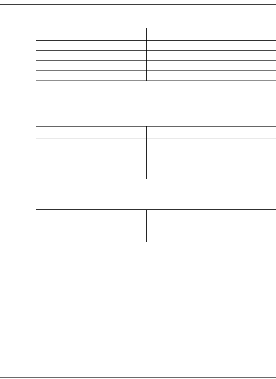
A-8 D9865 Satellite Receiver Installation and Operation Guide 4035197 Rev C
Power
AC Power Connector
General
Mechanics
Environment
Parameter Specification
Voltage Range 100 V to 240 V AC
Line Frequency 50/60 Hz
Power Consumption 35 W max.
LNB Power on satellite input +13 V/+ 18 V @ 350 mA max.
Parameter Specification
Height 2.36 in. (6.0 cm)
Width 11.69 in. (29.7 cm)
Depth 7.68 in. (19.5 cm)
Weight 5 lbs (2.3 kg)
Parameter Specification
Operating Temperature 0°C to 50°C (32°F to 122°F)
Storage -20°C to 70°C (-4°F to 158°F)

4035197 Rev C D9865 Satellite Receiver Installation and Operation Guide B-1
Appendix B
Default Settings
Overview
Introduction
The D9865 Satellite Receiver is factory configured with default settings unless you
have requested a custom factory configuration. This appendix lists the factory
default settings.
Topic See Page
Factory Default Settings B-2

B-2 D9865 Satellite Receiver Installation and Operation Guide 4035197 Rev C
Factory Default Settings
Tuning/Preset
Parameter Default
Modulation Type DVB-S2
Downlink 12.3 GHz
Symbol Rate 30.0 MS/s
Net Id 1
LO Select Off
LO Freq 1 10.75 GHz
LO Freq 2 0.0 GHz
Crossover 0.0 GHz
LNB Power 18V
DiSEqC Disable
DiSEqC Switch Off
Roll Off Factor (Web GUI only) .35
I/Q (Web GUI only) Auto

4035197 Rev C D9865 Satellite Receiver Installation and Operation Guide B-3
Factory Default Settings, Continued
Preset - Number 1
Preset - Number 2
Parameter Default
Preset Number 1
Preset Name ET
LNB Configuration 1
Modulation Type DVB-S
Downlink 11.795 GHz
Symbol Rate 20.0 MS/s
NetId 7
Parameter Default
Preset Number 2
Preset Name Enterprise
LNB Configuration 1
Modulation Type DVB-S
Downlink 11.851 GHz
Symbol Rate 30.5 MS/s
NetId 3

B-4 D9865 Satellite Receiver Installation and Operation Guide 4035197 Rev C
Factory Default Settings, Continued
Preset - Number 3
Preset - Number 4
Parameter Default
Preset Number 3
Preset Name Exterminator
LNB Configuration 1
Modulation Type DVB-S
Downlink 12.15 GHz
Symbol Rate 28.3465 MS/s
NetId 6
Parameter Default
Preset Number 4
Preset Name Spiderman
LNB Configuration 1
Modulation Type DVB-S
Downlink 12.25 GHz
Symbol Rate 30.8 MS/s
NetId 1

4035197 Rev C D9865 Satellite Receiver Installation and Operation Guide B-5
Factory Default Settings, Continued
Preset - Number 5
Preset - Number 6
Parameter Default
Preset Number 5
Preset Name Effete
LNB Configuration 1
Modulation Type DVB-S2
Downlink 12.31 GHz
Symbol Rate 30.0 Ms/s
NetId 1
Parameter Default
Preset Number 6
Preset Name Encounter
LNB Configuration 1
Modulation Type DVB-S
Downlink 12.39 GHz
Symbol Rate 45.00 Ms/s
NetId 4

B-6 D9865 Satellite Receiver Installation and Operation Guide 4035197 Rev C
Factory Default Settings, Continued
Preset - Number 7
Preset - Number 8
Parameter Default
Preset Number 7
Preset Name Ebenezer
LNB Configuration 1
Modulation Type DVB-S
Downlink 12.45 GHz
Symbol Rate 30.5 MS/s
NetId 1
Parameter Default
Preset Number 8
Preset Name Big Originator
LNB Configuration 1
Modulation Type DVB-S
Downlink 12.604 GHz
Symbol Rate 28.3465 MS/s
NetId 5
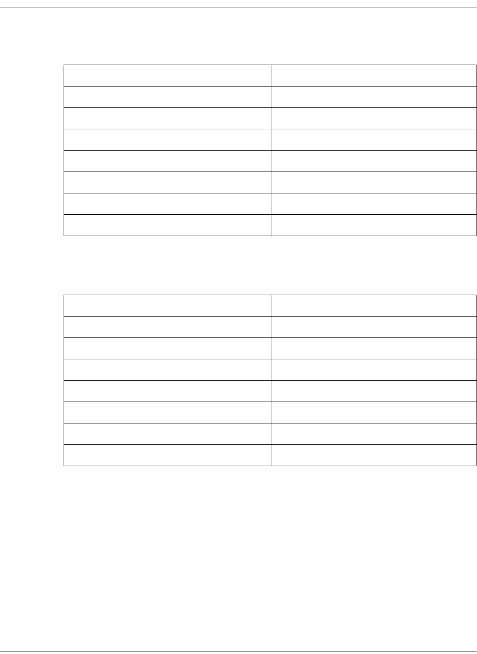
4035197 Rev C D9865 Satellite Receiver Installation and Operation Guide B-7
Factory Default Settings, Continued
Preset - Number 9 to 63
Preset - Number 64
Parameter Default
Preset Number 9 to 63
Preset Name Network name
LNB Configuration 1
Modulation Type DVB-S
Downlink 12.25 GHz
Symbol Rate 10.0 MS/s
NetId 1
Parameter Default
Preset Number 64
Preset Name Network name
LNB Configuration 10
Modulation Type DVB-S2
Downlink 12.30 GHz
Symbol Rate 30 MS/s
NetId 1
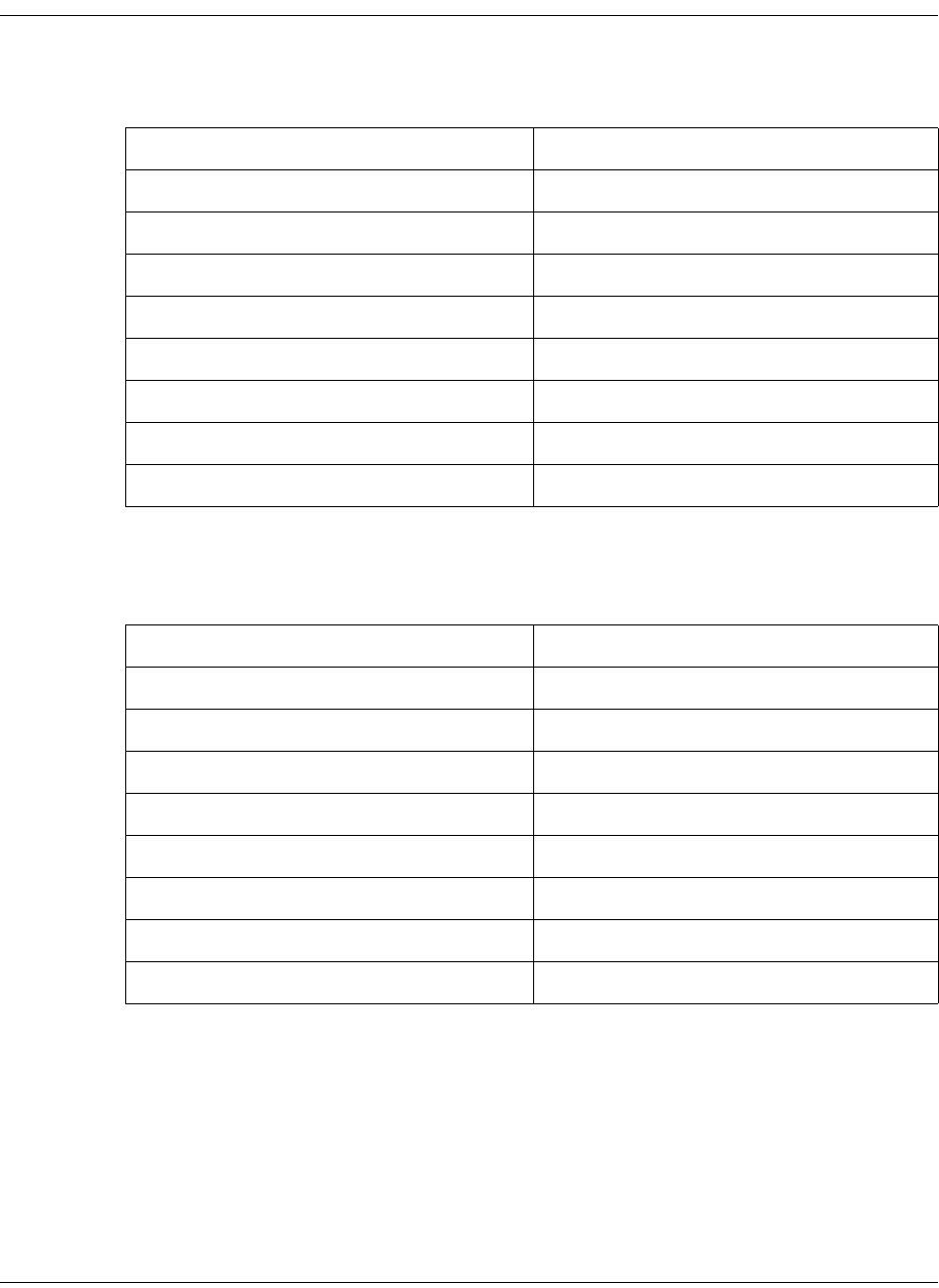
B-8 D9865 Satellite Receiver Installation and Operation Guide 4035197 Rev C
Factory Default Settings, Continued
LNB Setup - Configuration 1 to 9
LNB Setup - Configuration 10
Parameter Default
LNB Configuration 1 to 9
LNB Power Off
LO Freq1 5.15 GHz
LO Freq2 0.0 GHz
Crossover 0.0 GHz
LO Select Off
DiSEqC Disable
DiSEqC Switch Off
Parameter Default
LNB Configuration 10
LNB Power 18-H
LO Freq1 10.75
LO Freq2 0.0 GHz
Crossover 0.0 GHz
LO Select Off
DiSEqC Disable
DiSEqC Switch Off
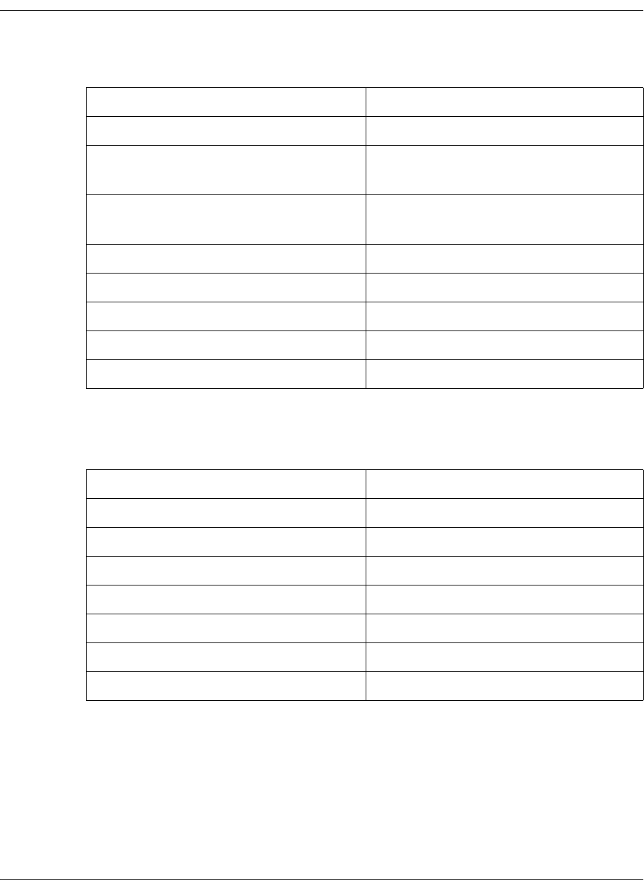
4035197 Rev C D9865 Satellite Receiver Installation and Operation Guide B-9
Factory Default Settings, Continued
Video Setup
Subtitle Setup
Parameter Default
HD Video Output Auto
SD Video Output For NTSC Unit: NTSC
For PAL Unit: PAL-B
TV Channel For NTSC: 3
For PAL: 21
TV Aspect Ratio 4:3
Aspect Ratio Convert None
Closed Caption Auto
Wide Screen Signalling (Web GUI only) Auto Create
Enable Banner Display (Web GUI only) Enabled
Parameter Default
Subtitle Control Off
Imitext Color Auto
Imitext Shade Auto
Imitext Position Standard
Subtitle Language eng
Language Entry (Web GUI only) eng
PMT Order (Web GUI only) First
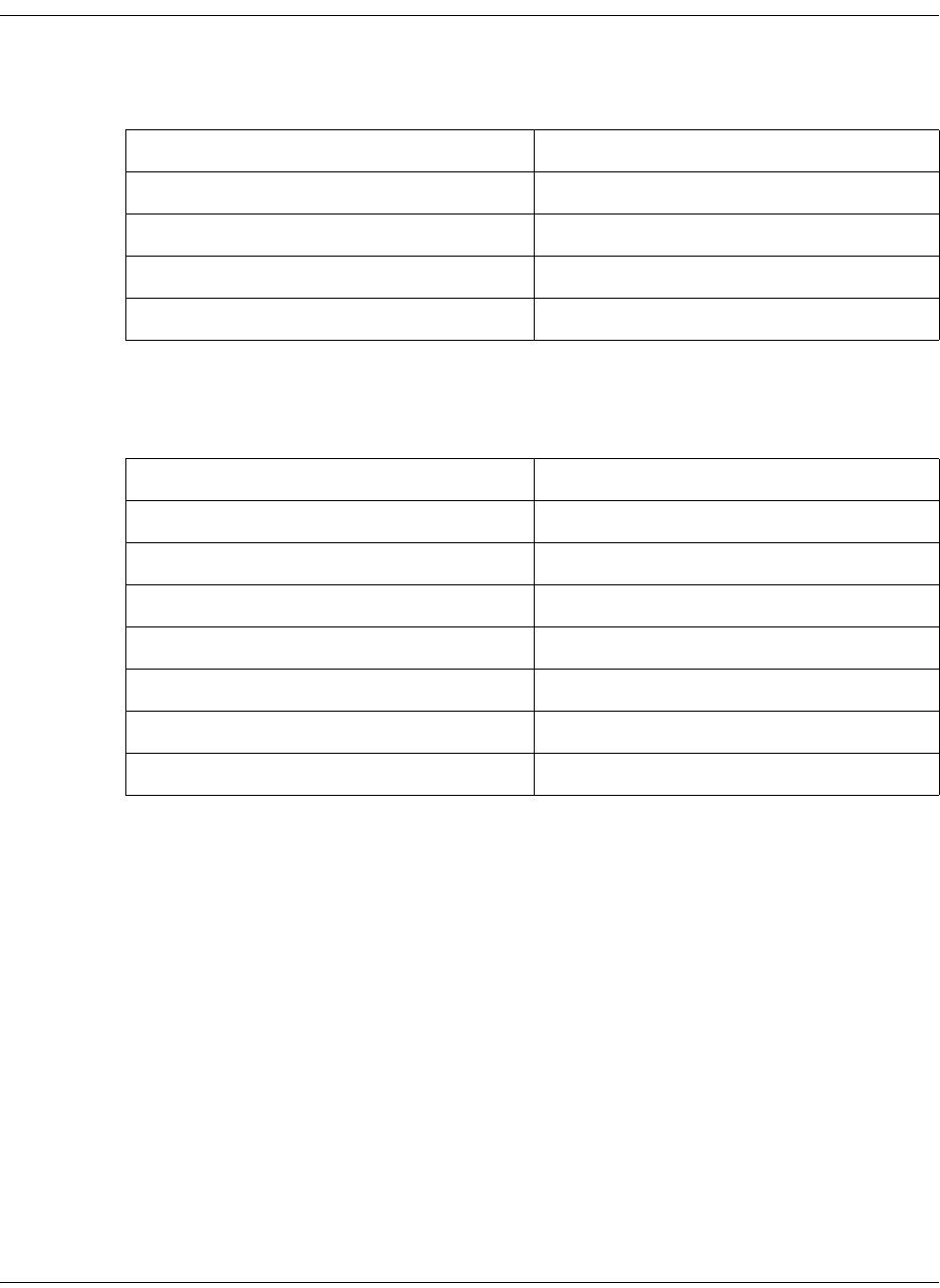
B-10 D9865 Satellite Receiver Installation and Operation Guide 4035197 Rev C
Factory Default Settings, Continued
Audio Setup
Administration
Parameter Default
Stereo/Mono Stereo
DRC Mode RF mode
Digital Audio Preference PCM
Audio PMT Source AUD1
Parameter Default
POV mode Std
Lock level 0
Menu transparency None
IR remote Enable
Date format YYYY-MM-DD
Time format 24 Hour
Time offset +05:30
4035197 Rev C D9865 Satellite Receiver Installation and Operation Guide B-11
Factory Default Settings, Continued
POV Mode
Advanced Administration
IP Setup
Unicast IP Setup
By default, the Unicast routes list is empty.
Multicast IP Setup
By default, the Unicast routes list is empty.
Parameter Default
CA Mode Std
Acquisition Mode Basic
Tuning Source NIT
Service List Mode Rigorous
BAT No
NIT Yes
SDT Yes
PAT Yes
Parameter Default
Set Lock Level Password 1234
Parameter Default
Filter Mode Forward All
MPE Optimization High Bitrate

B-12 D9865 Satellite Receiver Installation and Operation Guide 4035197 Rev C
Factory Default Settings, Continued
Trap Destination Setup
SNMP
Noise Cutoffs
Download
Parameter Default
Trap Destination Address 19.131.244.002
Community String “public”
Parameter Default
Read Community String public
Write Community String public
System Name (Web GUI only) sysname
System Location (Web GUI only) Toronto
System Contact (Web GUI only) 416-321-XXXX
Parameter Default
Noise Cutoffs Enable
DVB-S/DVB-S2 TS Cut Off 0.0 dB
DVB-S/DVB-S2 TS Restore 0.1 dB
DVB-S/DVB-S2 Audio Cut Off 0.0 dB
DVB-S/DVB-S2 Audio Restore 0.1 dB
Parameter Default
DL Mode Always
4035197 Rev C D9865 Satellite Receiver Installation and Operation Guide B-13
Factory Default Settings, Continued
CI Setup (Web GUI only)
Import/Export (Web GUI only)
Alarms and Warnings
Parameter Default
Decryption Mode On
CI CAM QUERY Support Disable
CI CAM Auto Reset Disable
CA List Management Type Update All
TS/ONID Check Disable
Transport ID 0
Original Network ID 0
Parameter Default
Settings Filename file name
FTP User Name User
FTP Password USER
FTP Port Number 21
Parameter Default
AW Banner Disable

B-14 D9865 Satellite Receiver Installation and Operation Guide 4035197 Rev C

4035197 Rev C D9865 Satellite Receiver Installation and Operation Guide C-1
Appendix C
Lock Levels
Overview
Introduction
This appendix contains the lock levels for the D9865 Satellite Receiver.
In This Appendix
This appendix contains the following topics.
Topic See Page
D9865 Satellite Receiver Lock Levels C-2

C-2 D9865 Satellite Receiver Installation and Operation Guide 4035197 Rev C
D9865 Satellite Receiver Lock Levels
Four (4) lock levels (0, 1, 2, 3, and 4) are available for protecting your receiver and its
settings against unauthorized use or modification (see the table below for full
details).
If a change made to the current Lock Level setting is not saved, the previously
saved setting is restored.
Note: The user cannot select NONE as a Lock Level.
Video
Level Description
0 All settings are unlocked (receiver lockout disabled)
1 All settings are unlocked except Preset option.
2 All settings are unlocked except Preset & LNB Setup
and Audio/Video options.
3All settings locked (access via password only).
4 All settings locked (can be changed via PNC uplink
signal only)
Parameter Lock Level
Channel Up 2
Channel Down 2
Volume Up 3
Volume Down 3
Power On/Standby 3
Channel Number via
Remote Control
2
IR Mute via Remote
Control
3
IR Volume Up 3
IR Volume Down 3
IR Channel Up 2
IR Channel Down 2
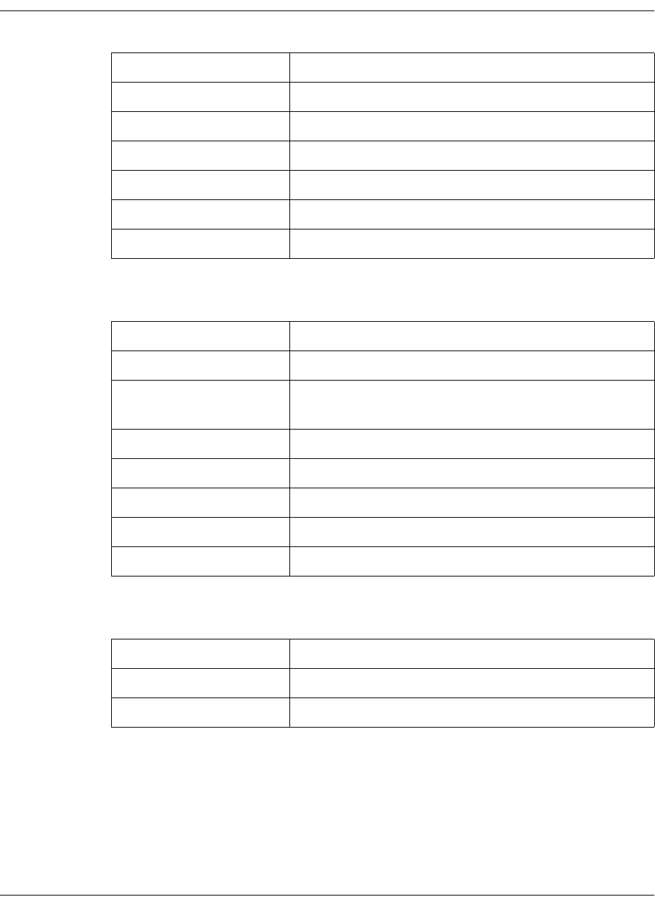
4035197 Rev C D9865 Satellite Receiver Installation and Operation Guide C-3
D9865 Satellite Receiver Lock Levels, Continued
All Screens
Channel List
Parameter Lock Level
IR Last Channel 2
IR FAV key 3
IR NAV key 3
IR EPG key 3
IR Setup key 3
Menu 3
Parameter Lock Level
Power On/Standby 3
IR Mute via Remote
Control
3
IR Volume Up 3
IR Volume Down 3
IR Channel Up 2
IR Channel Down 2
IR Last Channel 2
Parameter Lock Level
Scroll up and down 3
OK to select channel 2
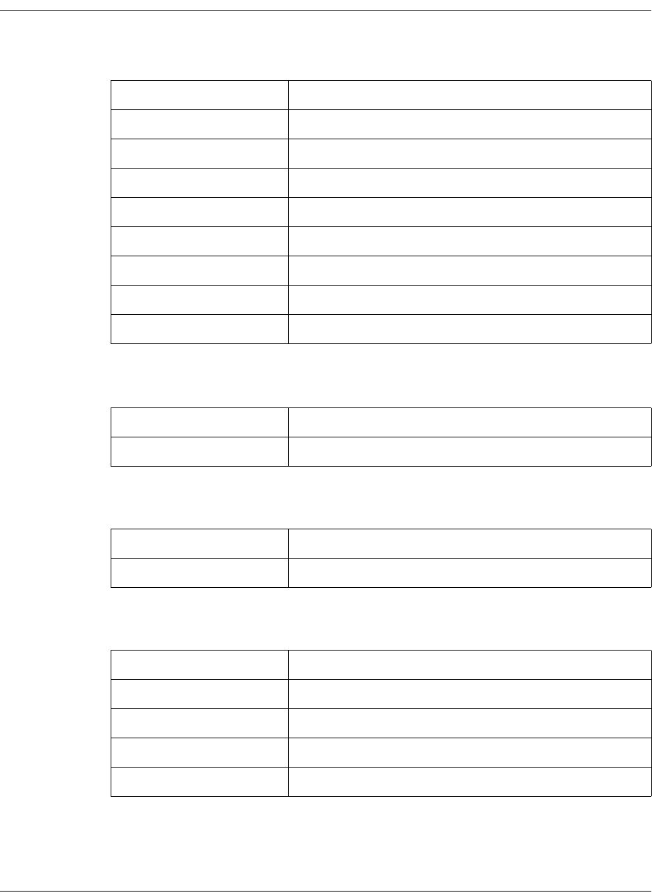
C-4 D9865 Satellite Receiver Installation and Operation Guide 4035197 Rev C
D9865 Satellite Receiver Lock Levels, Continued
EPG Grid
EPG Info
NAVigator Info
Timers
Parameter Lock Level
Scroll up and down 3
Scroll left and right 3
Next Day 3
Previous Day 3
Favorites 3
Timers 3
OK to select channel 2
OK to view future Info 3
Parameter Lock Level
Set Timer 2
Parameter Lock Level
Set Timer 2
Parameter Lock Level
Scroll up and down 3
Delete 2
Edit (to view) 3
Edit (Save button) 2
4035197 Rev C D9865 Satellite Receiver Installation and Operation Guide C-5
D9865 Satellite Receiver Lock Levels, Continued
Favorites
Edit Favorites
Timers
Parameter Lock Level
Delete 2
New 2
Edit (to view) 3
Edit (Save button) 2
Move 2
Select 2
Parameter Lock Level
Delete 2
Edit (to view) 3
Edit (Save button) 2
Move 2
Parameter Lock Level
Delete 2
Edit (to view) 3
Edit (Save button) 2
C-6 D9865 Satellite Receiver Installation and Operation Guide 4035197 Rev C
D9865 Satellite Receiver Lock Levels, Continued
One Button Channel Change (button presses)
Tuning/Preset
Tuning/Preset: Preset
Tuning/Preset:Preset:LNB
Parameter Lock Level
Red 2
Green 2
Yellow 2
Blue 2
Parameter Lock Level
Change Tuning
Parameters and Save
1
Parameter Lock Level
Change preset number 3
Edit preset tuning
parameters
1
Edit preset LNB
configuration number
1
Save preset 1
Activate preset 1
Parameter Lock Level
Change LNB
configuration number
3
Edit LNB settings 1
Save LNB settings 1
4035197 Rev C D9865 Satellite Receiver Installation and Operation Guide C-7
D9865 Satellite Receiver Lock Levels, Continued
Dish Setup (User Mode)
Dish Setup (Installer Mode)
Video Setup
Parameter Lock Level
Enter satellite number 1
Select User Action 1
Do Action 1
Enter Installer mode 3
Parameter Lock Level
Enter satellite number 1
Enter absolute position 1
Select installer action 1
Change DiSEqC enable/
disable state
1
Adjust dish position 1
Enter user mode 3
Parameter Lock Level
HD Video Output 2
SD Video Output 2
TV Channel 2
TV Aspect Ratio 2
Aspect Ratio Convert 2
Closed Caption 2
C-8 D9865 Satellite Receiver Installation and Operation Guide 4035197 Rev C
D9865 Satellite Receiver Lock Levels, Continued
Subtitles
Audio Setup
Administration
Parameter Lock Level
Subtitle Control 2
Imitext Color 2
Imitext Shade 2
Imitext Position 2
Subtitle Language 2
Parameter Lock Level
Stereo/Mono 2
Dolby Digital Mode 2
Digital Audio
Preference
2
Audio PMT Source 2
Parameter Lock Level
POV Mode 1
Lock Level 3
Menu Transparency 2
IR Remote 2
Date Format 2
Time Format 2
Time Offset 2
4035197 Rev C D9865 Satellite Receiver Installation and Operation Guide C-9
D9865 Satellite Receiver Lock Levels, Continued
Advanced Administration
POV Mode
IP Setup
Parameter Lock Level
Set Lock Level Password 0
Reboot 2
Factory Reset (F/R) 0
Rst Login 0
Parameter Lock Level
CA Mode 1
Acquisition Mode 1
Tuning Source 1
Service List Mode 1
BAT 1
NIT 1
SDT 1
PAT 1
Parameter Lock Level
Filter Mode 0
MPE Optimization 0
Next Port 2
Set IP Address (button) 2
C-10 D9865 Satellite Receiver Installation and Operation Guide 4035197 Rev C
D9865 Satellite Receiver Lock Levels, Continued
Change IP Address
Unicast IP Setup
Multicast IP Setup
SNMP Setup
Parameter Lock Level
IP Address 2
Gateway 2
Mask 2
Save 2
Parameter Lock Level
Add (button) 0
Edit 0
Delete 0
Parameter Lock Level
Add (button) 0
Edit 0
Delete 0
Parameter Lock Level
Read community string 0
Write community string 0
Trap Dest (button) 3
4035197 Rev C D9865 Satellite Receiver Installation and Operation Guide C-11
D9865 Satellite Receiver Lock Levels, Continued
Trap Destinations
Noise Cutoffs
Lock Level: 2
Alarms & Warnings
Alarm Setup
Lock Level: 2
Warning Setup
Lock Level: 2
Download
Parameter Lock Level
Add (button) 0
Edit 0
Delete 0
Parameter Lock Level
AW Banner 2
Alarm (button) 3
Warning (button) 3
Parameter Lock Level
DL Mode 2
Abort DL 2
Restart DL 2
Boot App (button) 3
C-12 D9865 Satellite Receiver Installation and Operation Guide 4035197 Rev C
D9865 Satellite Receiver Lock Levels, Continued
Bootable App Selection (Screen)
Info
Parameter Lock Level
Delete 2
Load App 2
Safe App 2
Parameter Lock Level
Service Information
(Channel Number)
2
Channel Information
(Channel Number)
2
ADP Status (Clear ADP
Count)
2
Device Status
Information (Clr Rst
Count)
2

4035197 Rev C D9865 Satellite Receiver Installation and Operation Guide D-1
Appendix D
Compliance
Applicable Notices and Disclaimer
FCC Notices
This equipment has been tested and found to comply with the limits for a TV
Interface device and Class B digital device according to Part 15 of FCC Rules. These
limits are designed to provide reasonable protection against harmful interference
when operated in a residential installation. This equipment generates, uses and can
radiate radio frequency energy, and if not installed and used in accordance with the
instructions supplied in this manual may cause harmful interference to radio
communications. However, there is no guarantee that interference will not occur in
a particular installation. If this equipment does cause harmful interference to radio
or television reception (which can be determined by turning the equipment off and
on), the user is encouraged to try to correct the interference by one or more of the
following measures.
• Reorient or relocate the television receiving antenna
• Increase the separation between the equipment and the receiver
• Connect the equipment to an AC outlet on a circuit different from that to which
the receiver is connected
• Contact your dealer/reseller or an experienced radio/TV technician for help
The user may find the booklet “Interference handbook” prepared by the Federal
Communications Commission helpful. This booklet is available from the U.S.
Government Printing Office, Washington, DC 20402, stock no. 004-000-00450-7.
Shielded cables should be used to interconnect this device with any other/
peripheral equipment (e.g., TV monitors, terminals, data sources, etc.) to ensure
compliance with Class B limits. Failure to do so may result in radio or TV
interference. Cables should be of braided shield construction with metal end shells.
The manufacturer is not responsible for any radio or TV interference resulting from
unauthorized modification of this equipment. It is the responsibility of the user to
correct such interference at the user’s expense.
Industry Canada Notice
This digital apparatus does not exceed the limits for Class B radio noise emissions
from digital apparatus as set out in the radio interference regulations of Industry
Canada.
Le present appareil numerique n’mete pas de bruits radioelectriques depassant les
limites applicables aux appareils numeriques de Class B prescrites dans le
reglement sur le brouillage radioelectrique edicte par Industrie Canada.

D-2 D9865 Satellite Receiver Installation and Operation Guide 4035197 Rev C
Applicable Notices and Disclaimer, Continued
Disclaimer
Cisco Systems, Inc. assumes no responsibility for errors or omissions that may
appear in this guide. We reserve the right to change this guide at any time without
notice.

4035197 Rev C D9865 Satellite Receiver Installation and Operation Guide D-3
Scientific-Atlanta Europe NV
Luipaardstraat 12
8500 Kortrijk
Belgium
Declaration of Conformity
The Product: Satellite Receiver
Model Number: D9865
Ratings: 100-240V~, 50/60Hz, 0.5Amax
Has been designed and manufactured in accordance with the following Harmonised Standards:
Number and Date of Issue Title of Standard
EN 60065:2002 - Audio, video and similar electronic apparatus – Safety requirements
EN 55022:2006 / A1:2007
Class B - Limits and Methods of Measurement of Radio Interference Characteristics of
Information Technology Devices
EN 55013:2001/ A1:2003
/ A2:2006 - Electromagnetic Compatibility Requirements - Sound and Television
Broadcast Receivers and Associated Equipment
EN 55020:2007 - Sound and television broadcast receivers and associated equipment – Immunity
characteristics – Limits and methods of measurement
EN 55024:1998 /A1:2001
/ A2:2003 - Information technology equipment - Immunity characteristics - Limits and methods
of measurement
EN 61000-3-2:2001 - Electromagnetic Compatibility - Part 3: Limits Section 2: Limits for Harmonic
Current Emissions (Equipment Input Current less than 16A per phase)
According to the provisions of theLow Voltage Directive 2006/95/EC and the EMC Directive 2004/108/EC
Toronto, Canada, June 11, 2009
(Issue Place and date)
Scientific-Atlanta Canada Company (Digital Media Networks Business Unit)
(Company Name)
100 Middlefield Road, Scarborough, Ontario, Canada, M1S 4M6
(Company Address)
For the manufacturer: Steven Lawrence, Product Regulatory Compliance
(Signature, Name and Title)
File:D9865_EU_DoC1 www.scientificatlanta.com

D-4 D9865 Satellite Receiver Installation and Operation Guide 4035197 Rev C

Cisco Systems, Inc. 678.277.1000
5030 Sugarloaf Parkway, Box 465447 www.cisco.com
Lawrenceville, GA 30044
This document includes various trademarks of Cisco Systems, Inc. Please see the Notices section of this
document for a list of the Cisco Systems, Inc. trademarks used in this document.
All other trademarks mentioned in this document are the property of their respective owners.
Product and service availability is subject to change without notice.
© 2010 Cisco and/or its affiliates. All rights reserved.
October 2010 Printed In United States of America Part Number 4035197 Rev C
