Cisco Systems FV WiFi AP User Manual FM1200
Fluidmesh Networks LLC WiFi AP FM1200
UserManual.wiki
>
Cisco Systems
>
FV User Manual
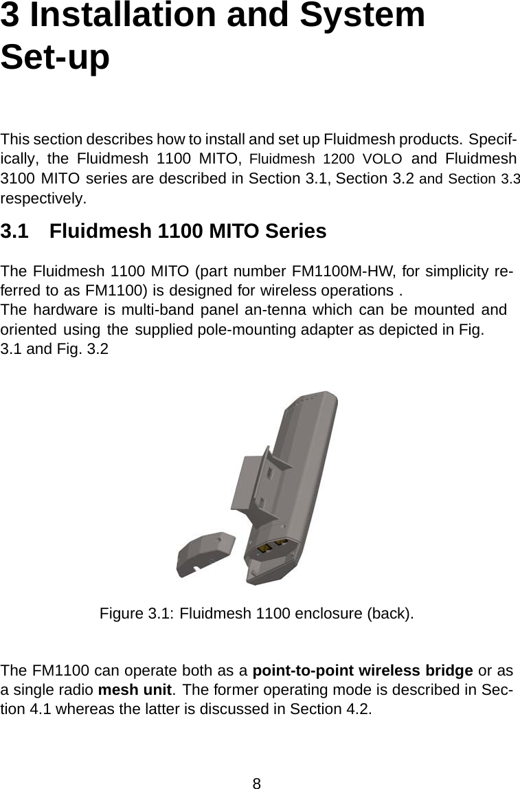
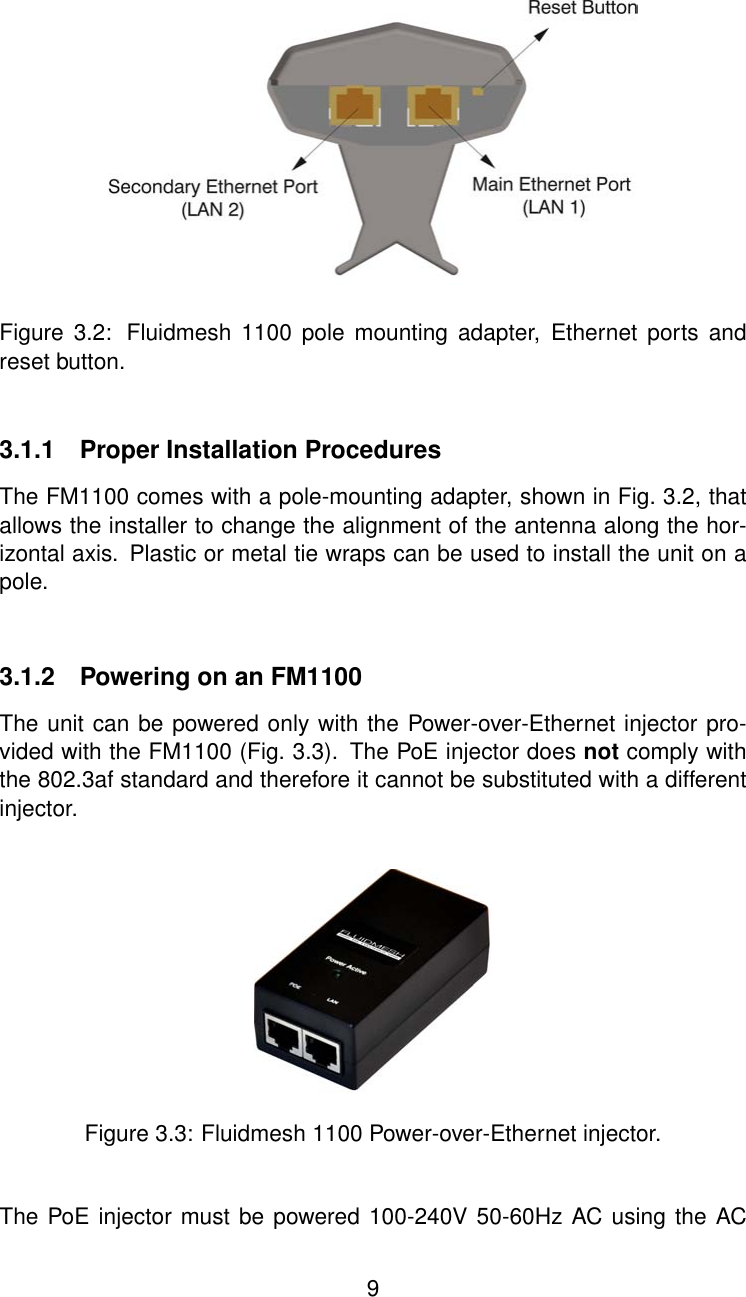
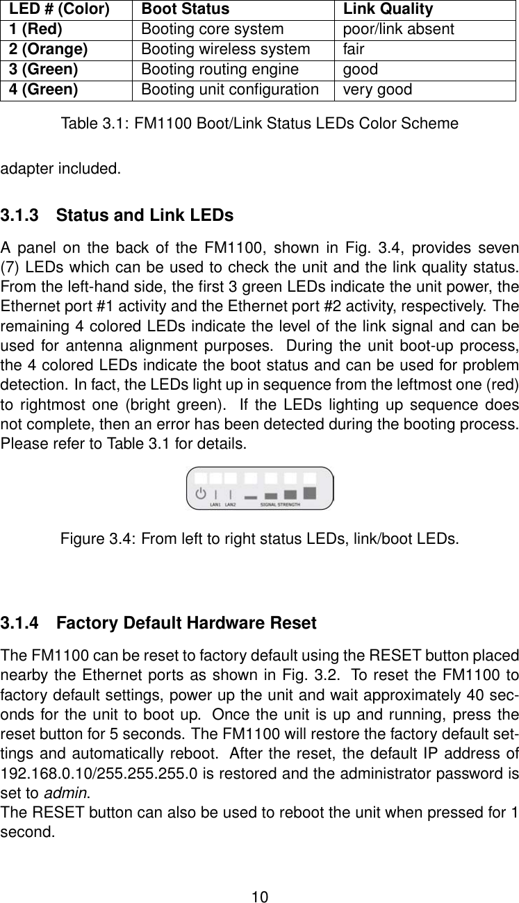
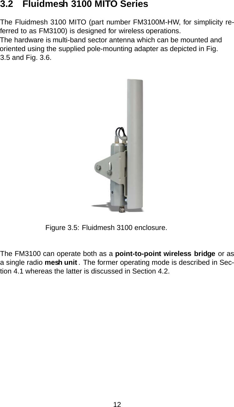
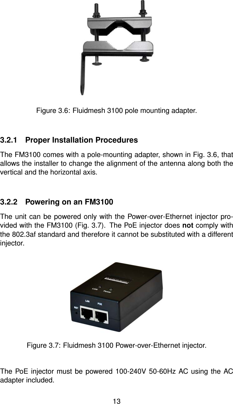
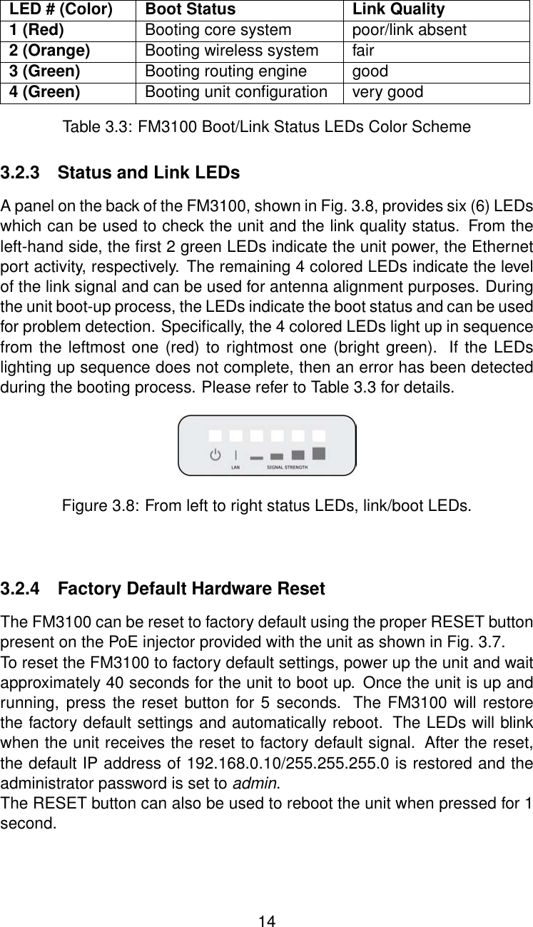
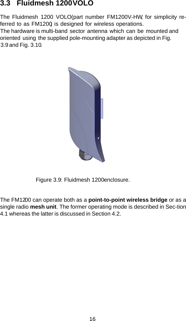
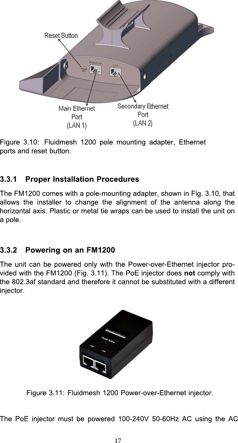
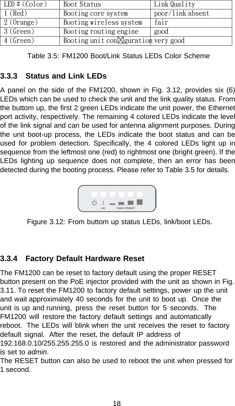
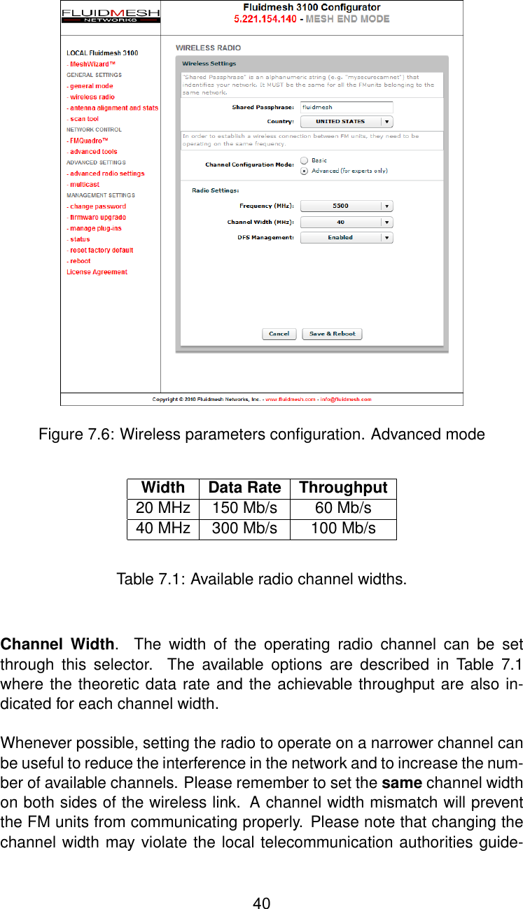
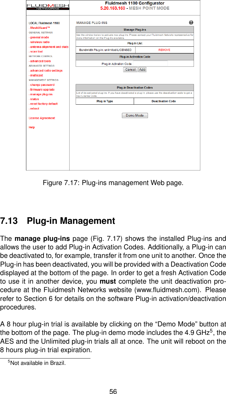
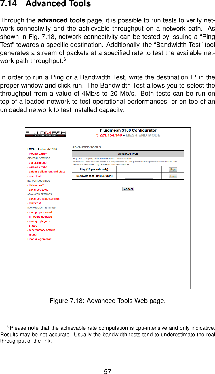
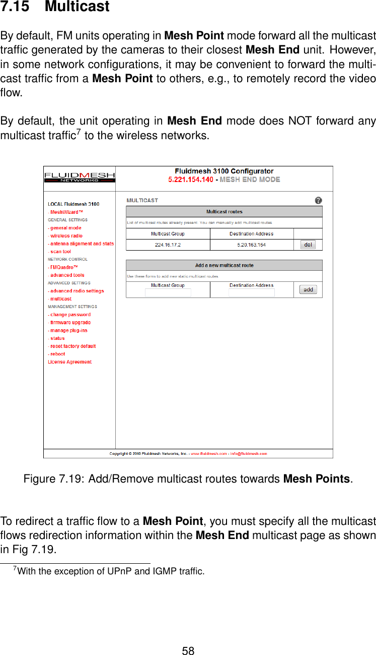
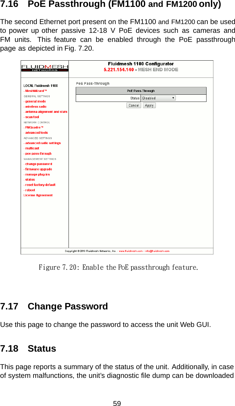
FM1200 user manual
Navigation menu
Upload a User Manual
Namespaces
Wiki Guide
HTML
PDF
Info
Views
User Manual
Discussion / Help
Navigation