Cisco Systems IPCS0226 IP Camera User Manual ipug
Cisco Systems Inc IP Camera ipug
UserManual.wiki
>
Cisco Systems
>
IPCS0226 User Manual
Manual
Navigation menu
Upload a User Manual
Namespaces
Wiki Guide
HTML
PDF
Info
Views
User Manual
Discussion / Help
Navigation
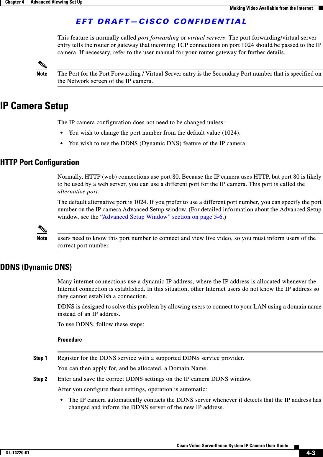
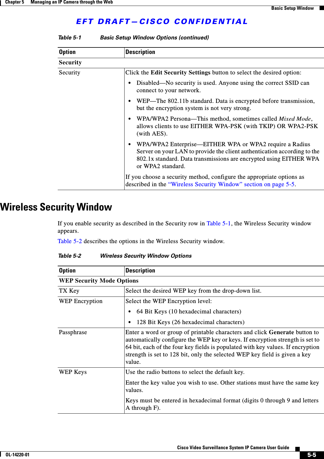
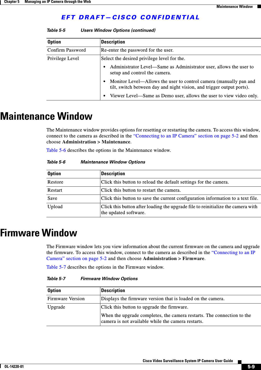
![EFT DRAFT—CISCO CONFIDENTIALA-1Cisco Video Surveillance System IP Camera User GuideOL-14220-01APPENDIXAStreaming Video/Audio SolutionStreaming video is a sequence of “moving images” that are sent in compressed form over the Internet and displayed by a viewer as they arrive. With streaming, a web user does not have to wait to download a large file before seeing the video or hearing the sound. Instead, the media is sent in a continuous stream and is played as it arrives. To snapshot a JPEG image from the Internet Camera with specified resolution and quality:http://<ip>/img/snapshot.cgi?[size=<value>]&[quality=<value>]Where:•ip is the IP address of the camera•value for size is a number 1 through 3, where: –1—320 x240–2—640 x 480–3—720 x 480•value for quality is a number 1 though 5, where:–1—Very high–2—High–3—Normal–4—Low–5—Very lowTo stream video through the RTP/RTSP protocol from Internet Camera (MPEG-4 mode only):http://<ip>/img/media.sdprtsp://<ip>/img/media.savWhere ip is the IP address of the camera Note Users need to specify the desired protocol in the players.](https://usermanual.wiki/Cisco-Systems/IPCS0226/User-Guide-875889-Page-47.png)