Cisco Systems IR829GW-LTE IR829 Integrated Services Router User Manual
Cisco Systems Inc IR829 Integrated Services Router Users Manual
UserManual.wiki
>
Cisco Systems
>
IR829GW LTE User Manual
Users Manual
Navigation menu
Upload a User Manual
Namespaces
Wiki Guide
HTML
PDF
Info
Views
User Manual
Discussion / Help
Navigation
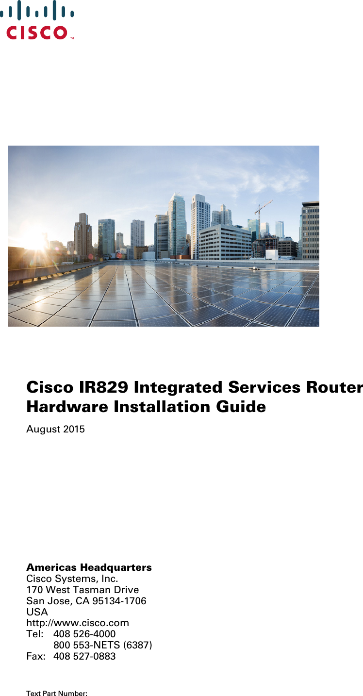


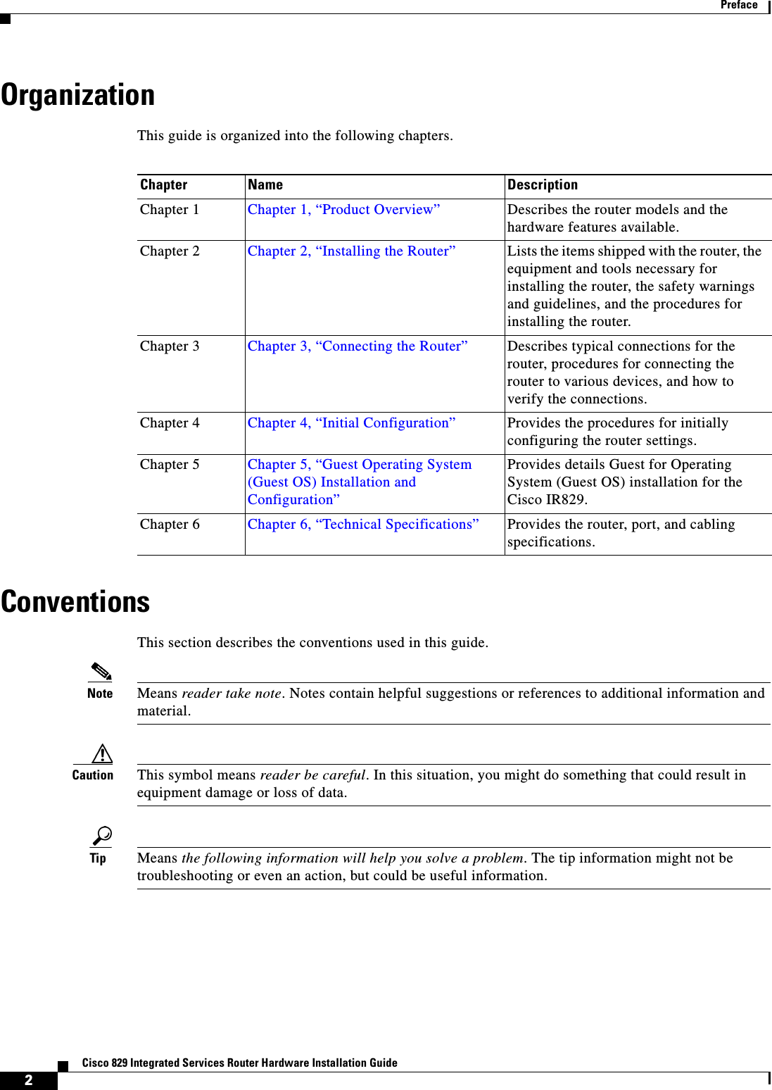
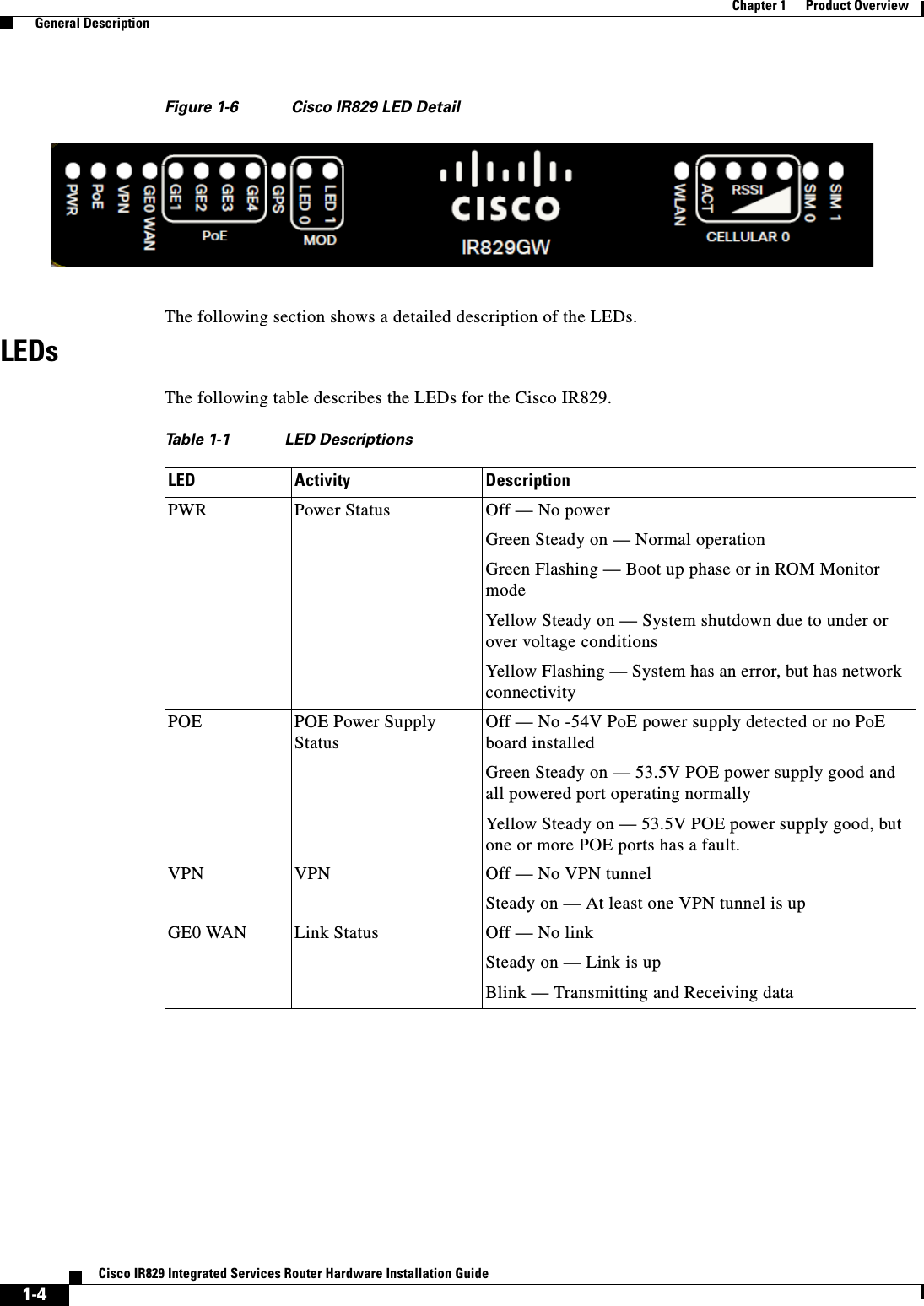
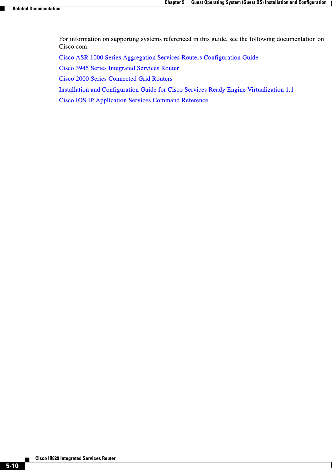
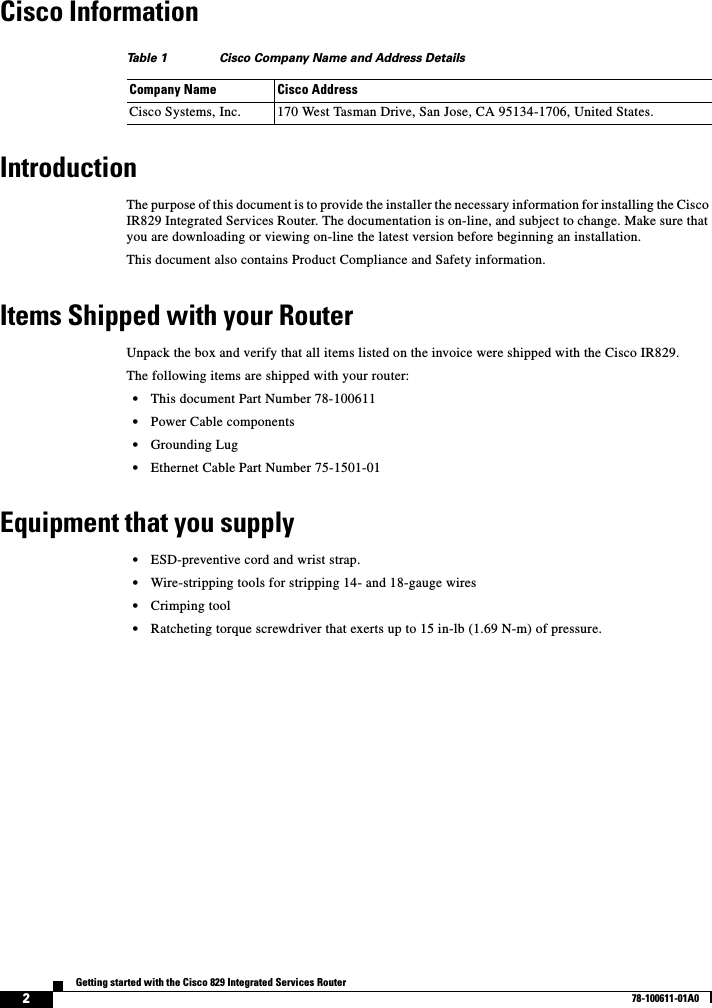
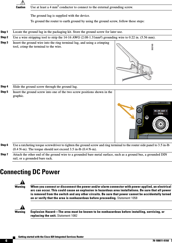
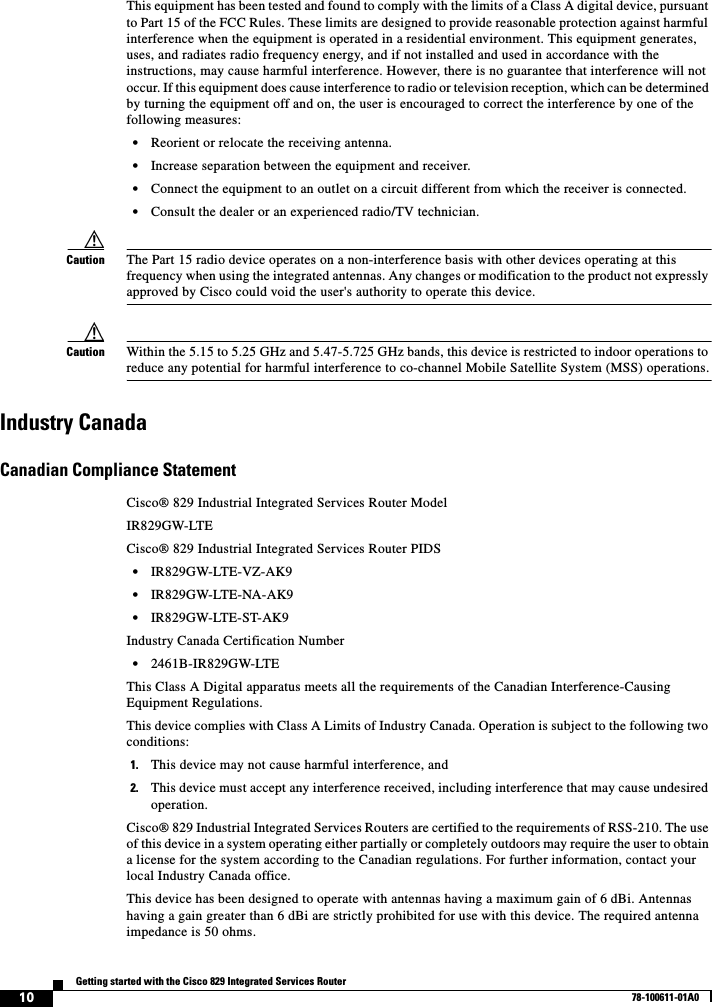
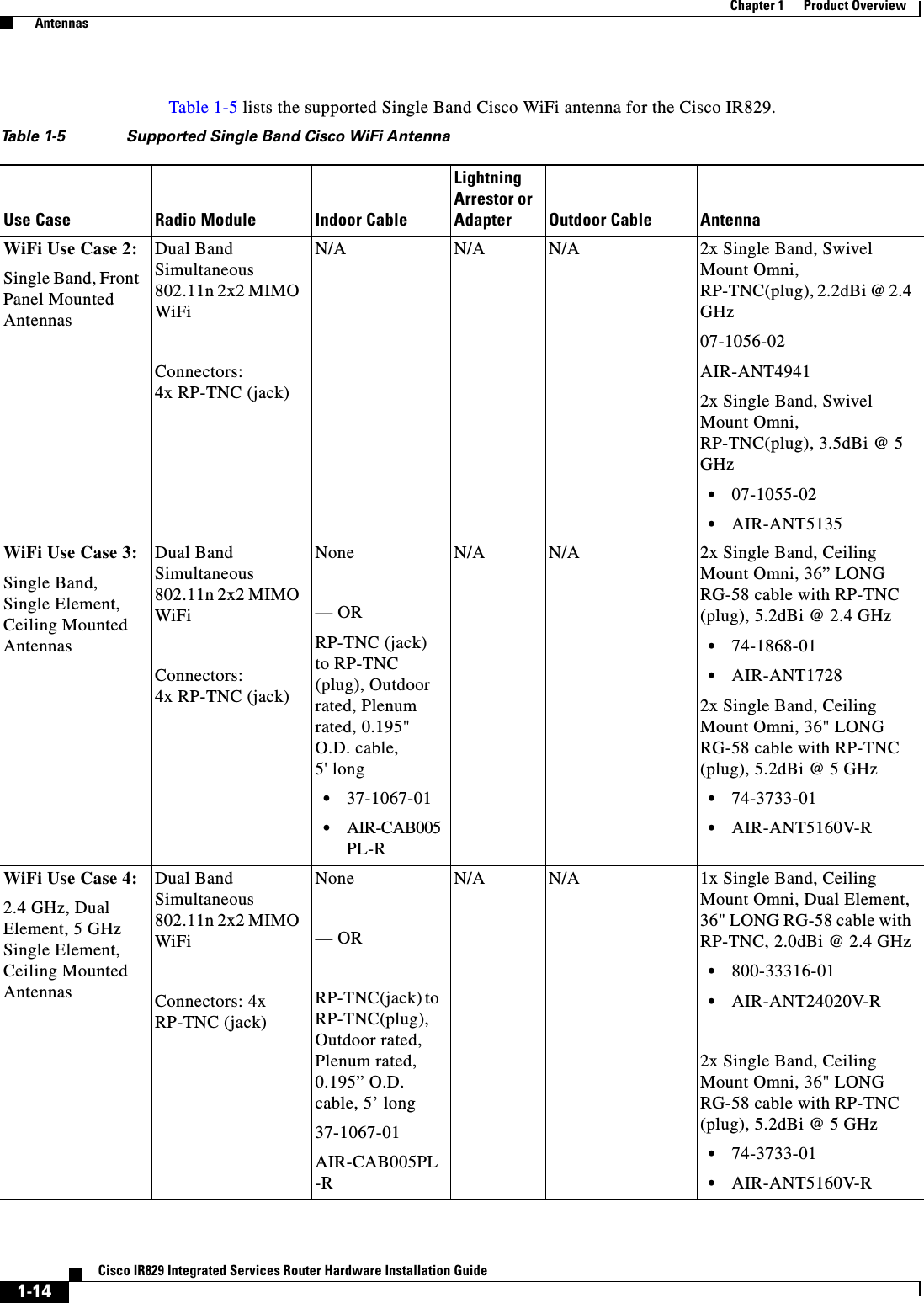
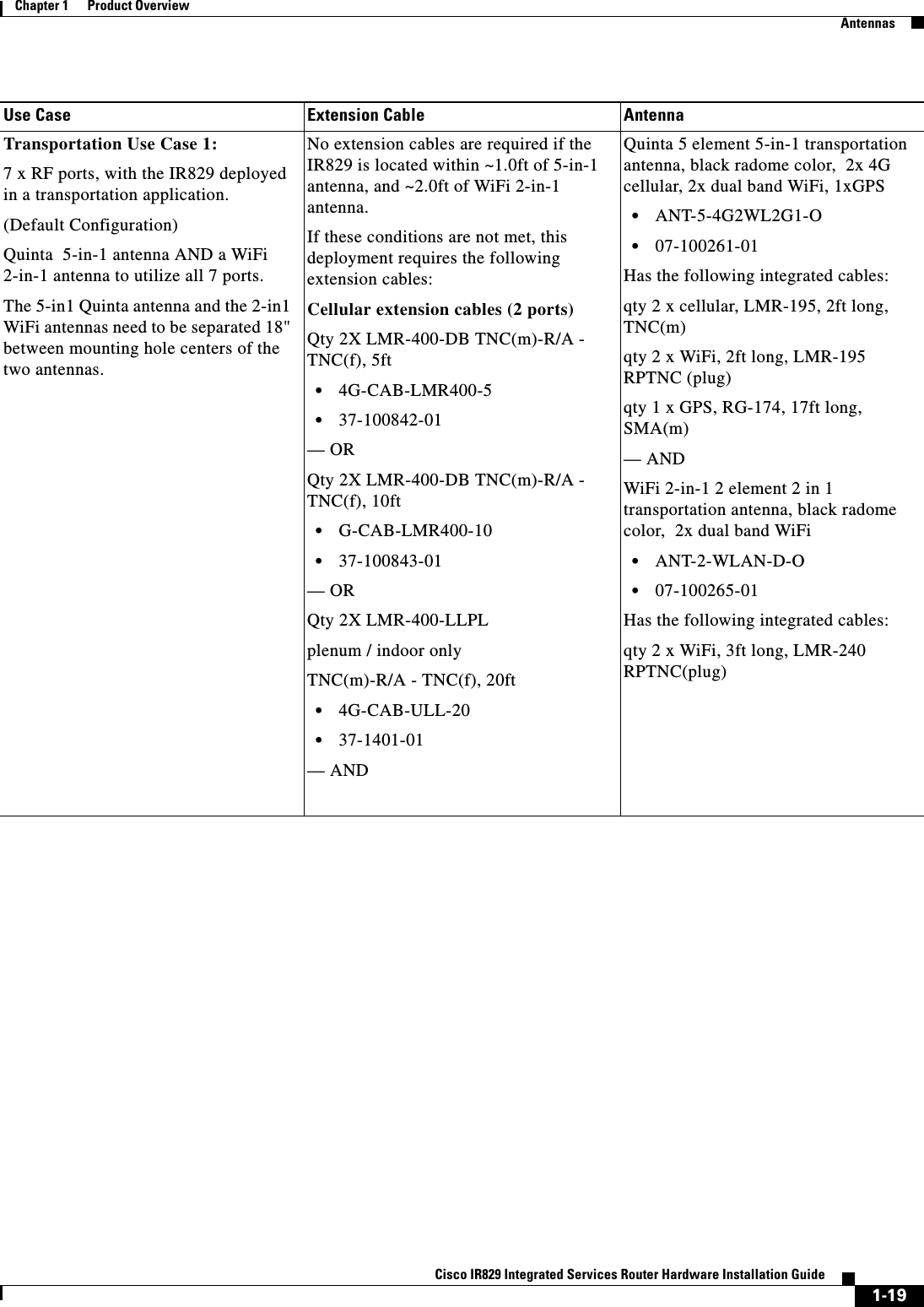
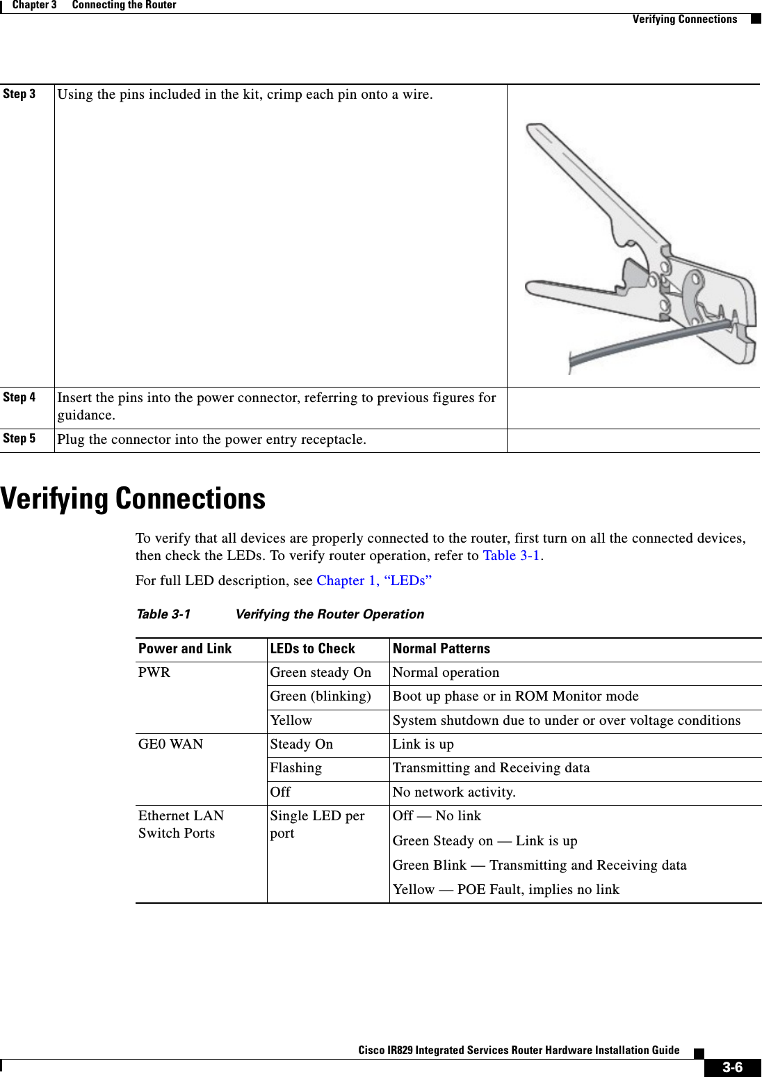
![1-5Cisco IR829 Integrated Services Router Hardware Installation GuideChapter 1 Product Overview General DescriptionFigure 1-7 RSSI LEDGPS GPS Status Off — GPS not configuredOn — GPS configured Slow Flash — GPS Acquiring in Standalone GPSFast Flash — GPS Acquiring in Assisted GPSNote Slow Flash is defined as the LED will be on for 0.25 seconds and off for 0.75 seconds. Fast Flash s defined as the LED will be on for 0.25 seconds and off for 0.25 seconds.MODEthernet LAN Switch Ports GE1-GE4] Single LED per PortLink Status/POE Status Off — No linkGreen Steady on — Link is upGreen Blink — Transmitting and Receiving dataYellow — POE Fault, implies no linkWLAN 2.4GHz5GHzOff — Radio is down (no SSID configured)Flashing Green — Bootloader, IOS Ethernet Initialization, IOS Start Up after system initialization.Green to Red to Yellow — Discovery/Join process.Rapid Flashing Green — Joined to a controllerSteady Green — One wireless client is associated.CELLULAR0/ CELLULAR1ACT Off — Module not powered onOn — Module is powered on and connected but not transmitting or receivingSlow Blink — Module is powered on and searching for connectionFast Blink — Module is transmitting or receiving.CELLULAR0/ CELLULAR1RSSI The RSSI LEDs are a 3 LED bar graph to indicate signal strength. Their functionality is described in the RSSI LED figure below.SIM0/SIM1 Sim cards Off — No USIMGreen — USIM installed and activeTable 1-1 LED Descriptions (continued)LED Activity DescriptionRSSI RSSI (2) RSSI (1) RSSI (0)Green Green Green/Yellow<110dBm Off Off Off-110 — 90dBm Off Off On - Yellow](https://usermanual.wiki/Cisco-Systems/IR829GW-LTE/User-Guide-2736232-Page-21.png)

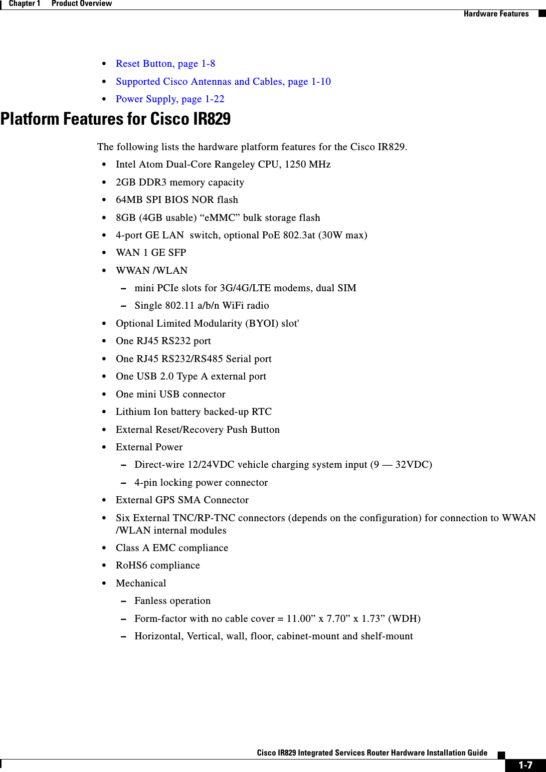
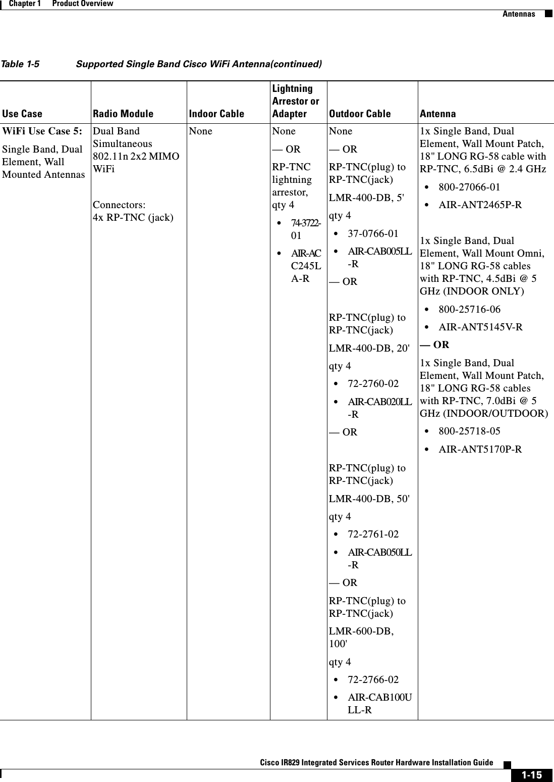

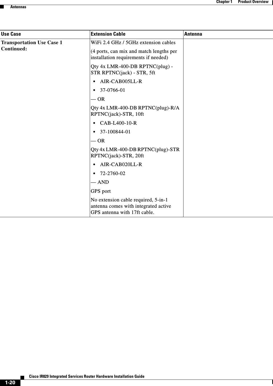

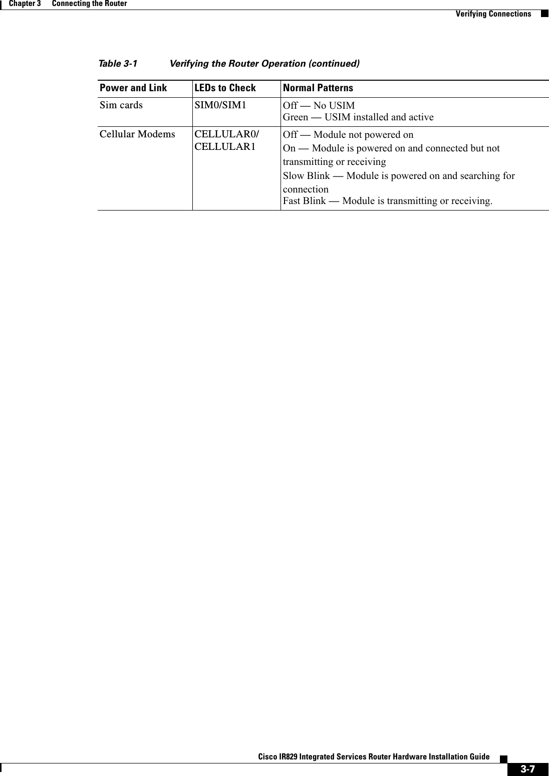
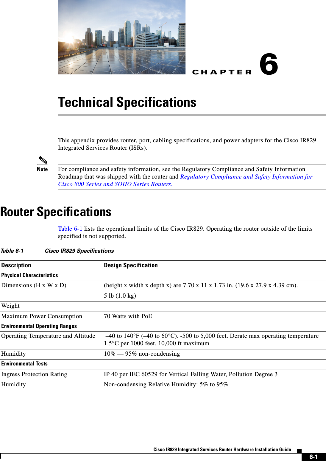
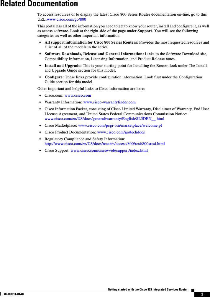
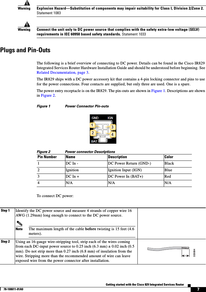
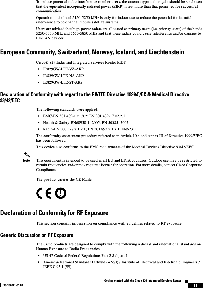
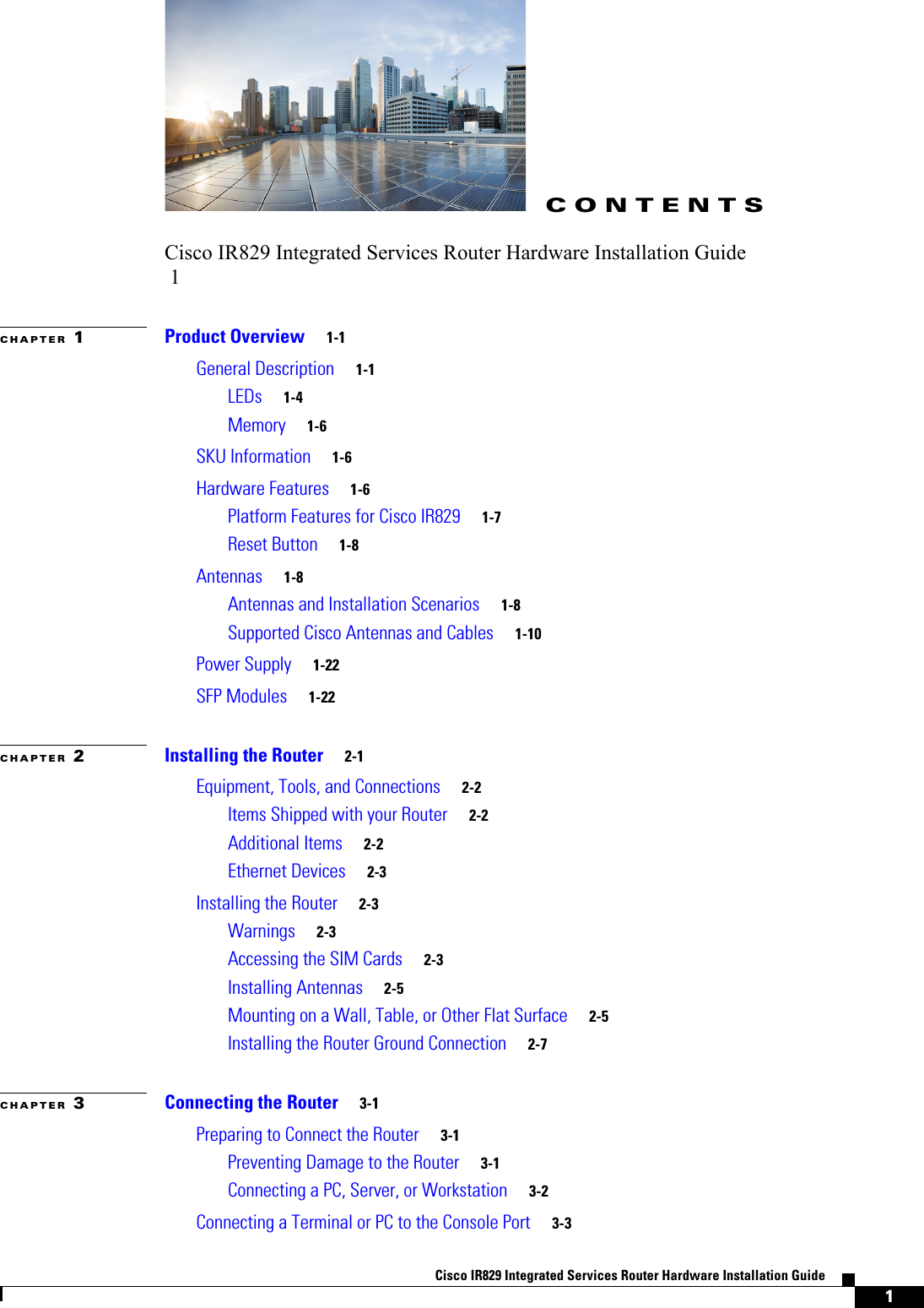
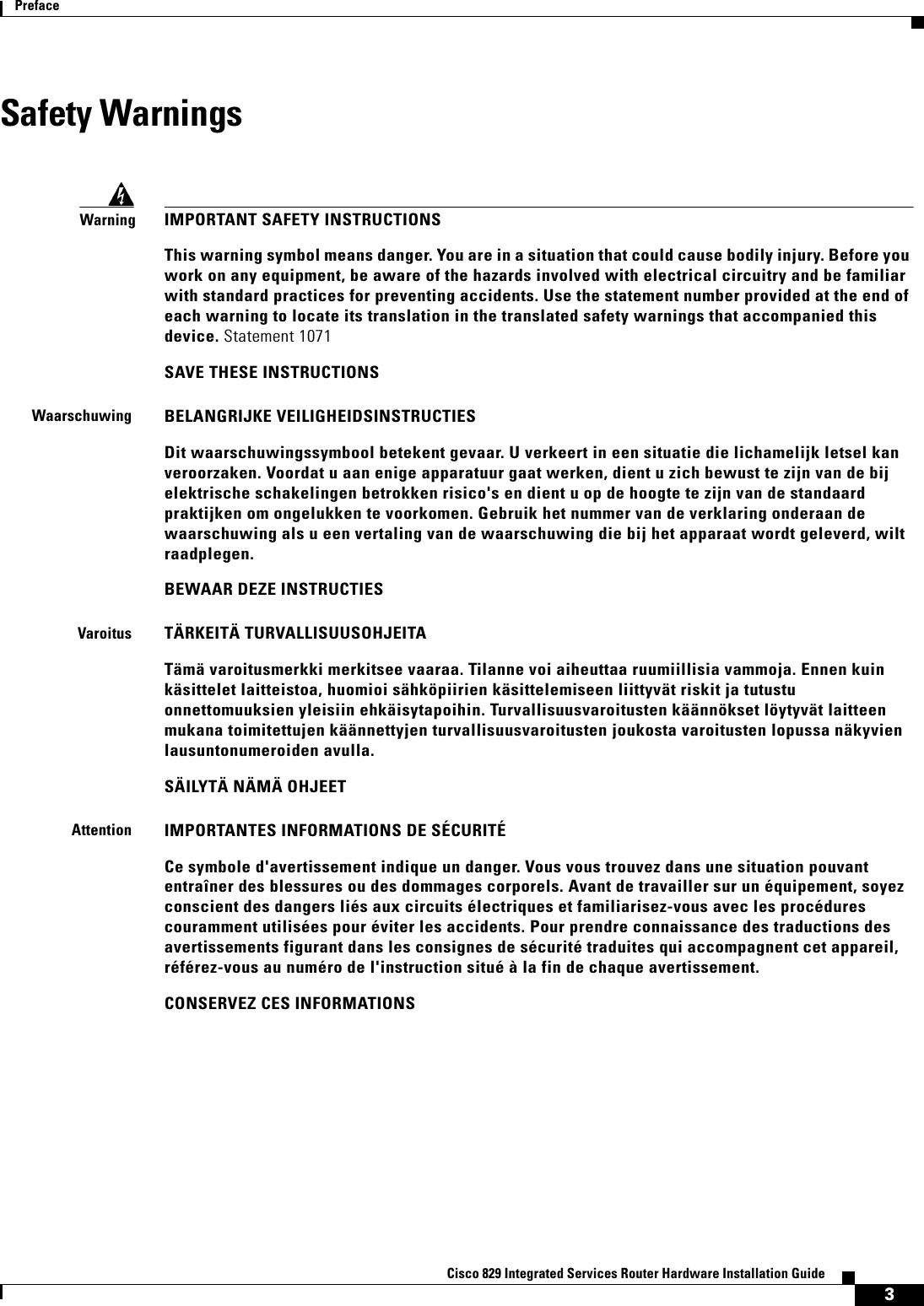
![CHAPTER4-1Cisco IR829 Integrated Services Router Hardware Installation Guide4Initial ConfigurationThis chapter provides instructions for initial configuration of the Cisco IR829 Integrated Services Routers (ISRs). To create the initial configuration, the setup command facility prompts you for basic information about your router and network.This chapter contains the following sections: • Setup Command Facility, page 4-1 • Verifying the Initial Configuration, page 4-4 • Where To Go From Here, page 4-4Setup Command FacilityThe setup command facility guides you through the configuration process by prompting you for the specific information that is needed to configure your system. Use the setup command facility to configure a hostname for the router, to set passwords, and to configure an interface for communication with the management network.To use the setup command facility, you must set up a console connection with the router and enter the privileged EXEC mode. To configure the initial router settings by using the setup command facility, follow these steps:Step 1 Set up a console connection to your router, and enter privileged EXEC mode. Step 2 In privileged EXEC mode, at the prompt, enter setup. yourname# setupThe following message is displayed:--- System Configuration Dialog ---Would you like to enter the initial configuration dialog? [yes/no]:You are now in the setup command facility.The prompts in the setup command facility vary, depending on your router model, on the installed interface modules, and on the software image. The following steps and the user entries (in bold) are shown as examples only.](https://usermanual.wiki/Cisco-Systems/IR829GW-LTE/User-Guide-2736232-Page-54.png)
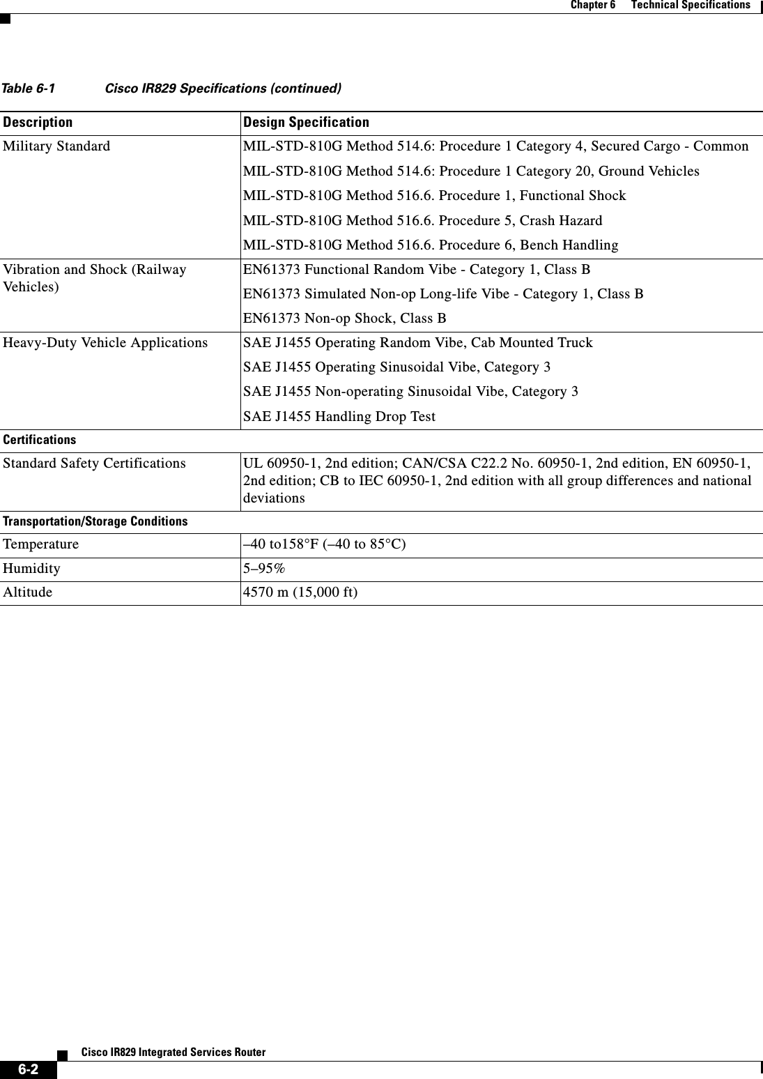
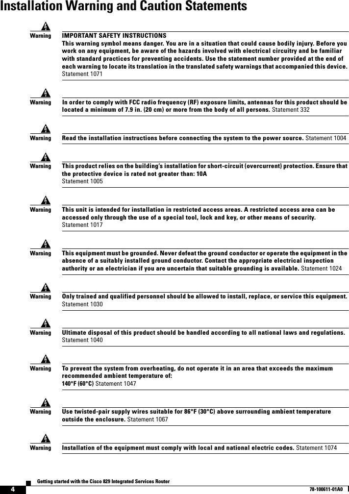
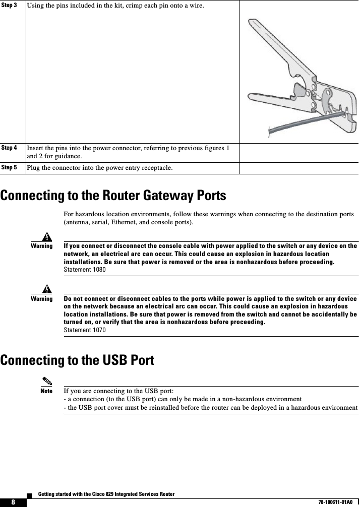
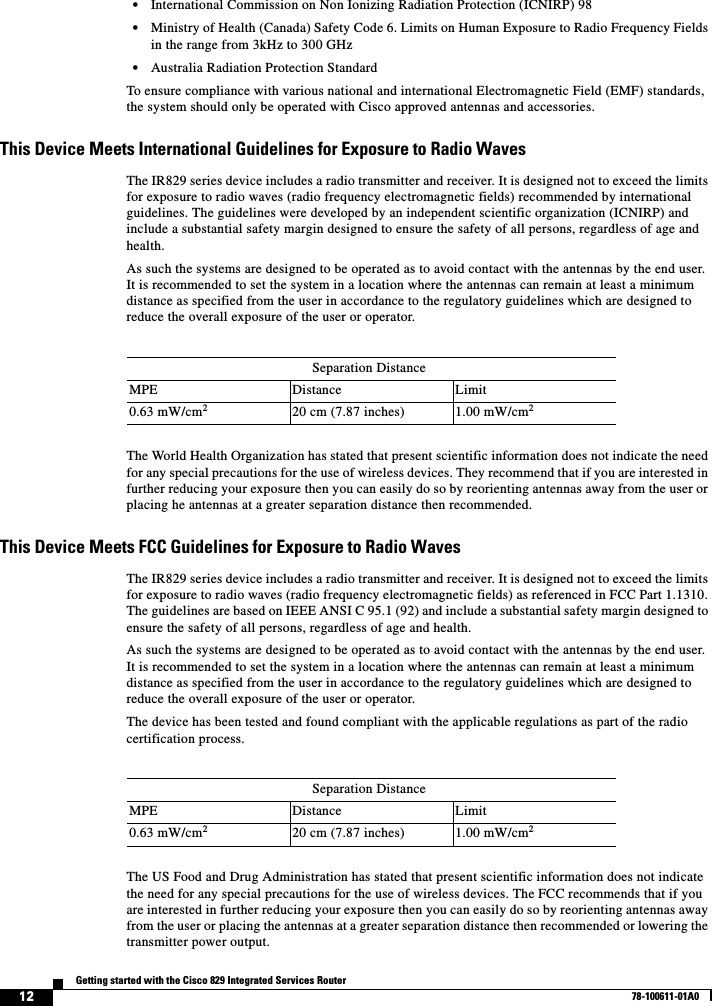
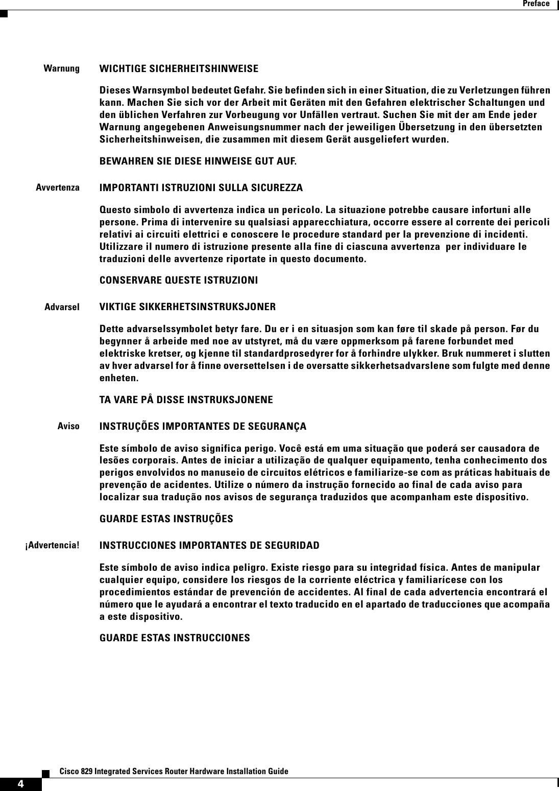
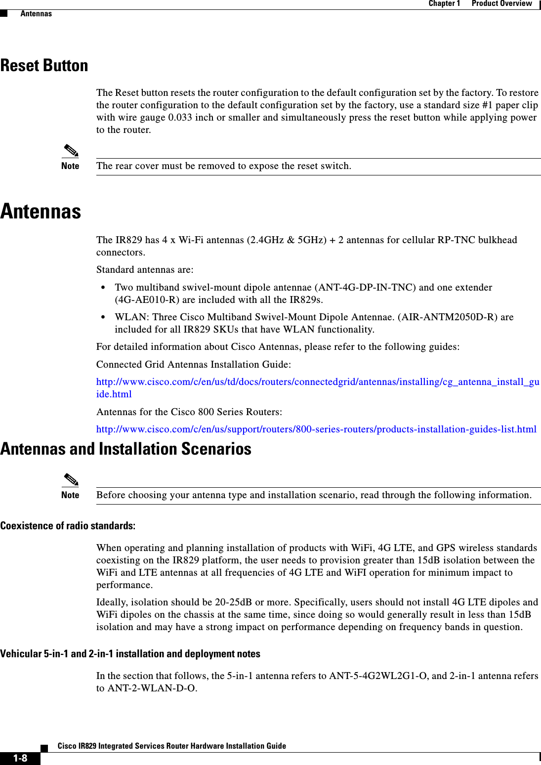
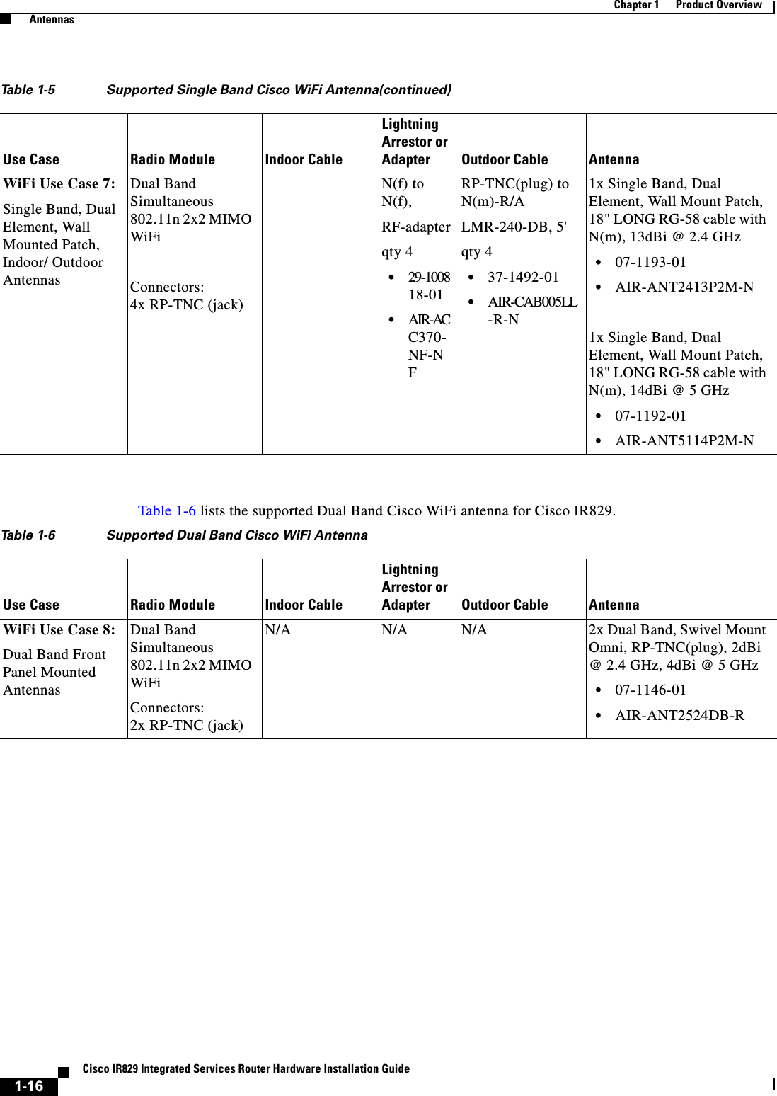
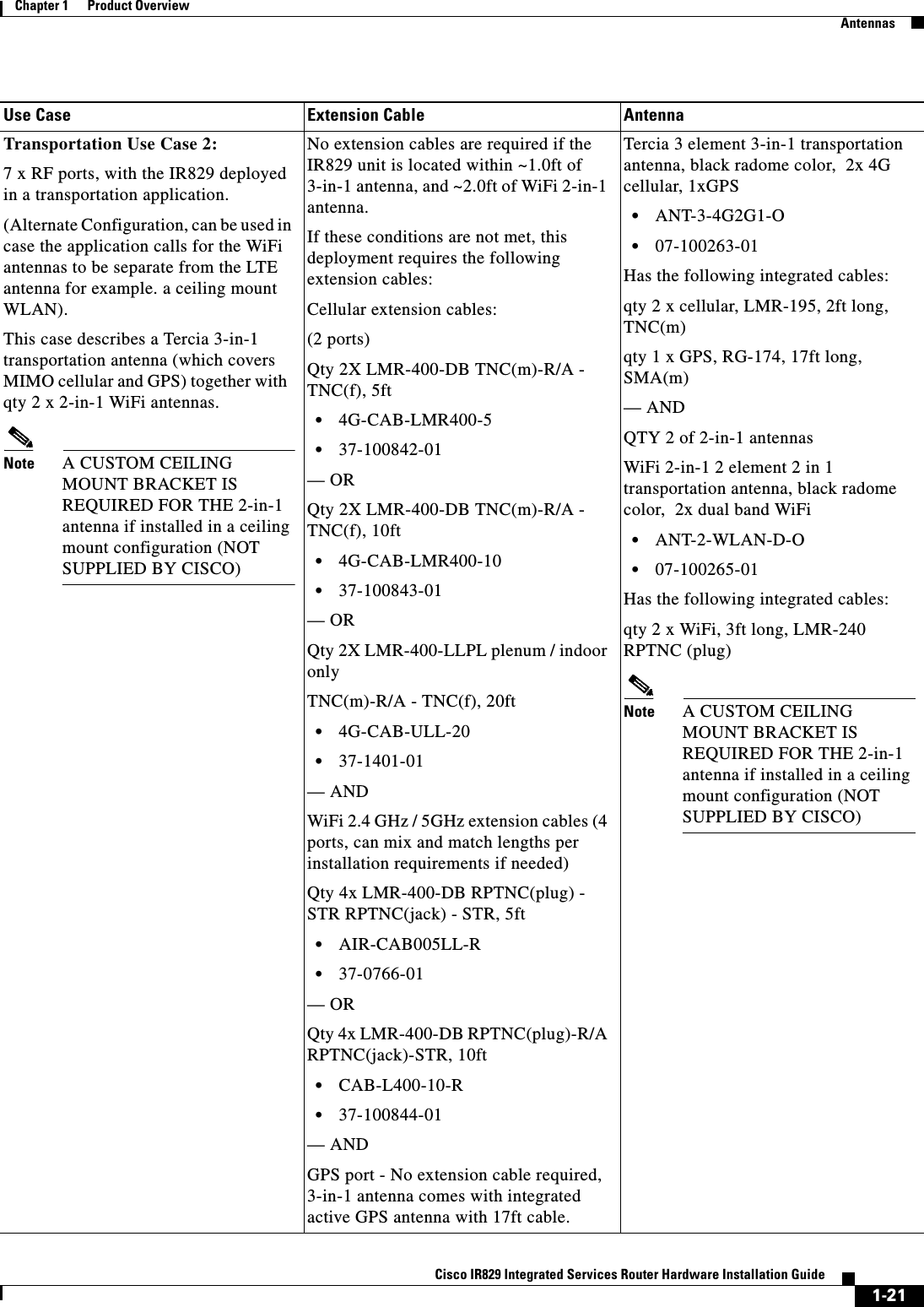
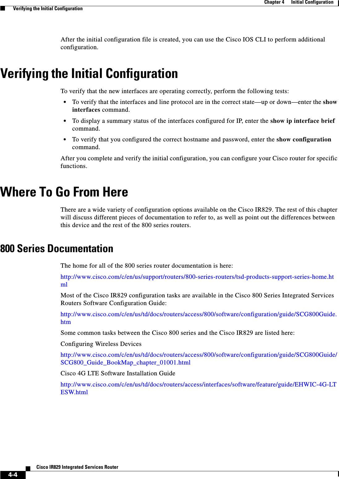
![4-2Cisco IR829 Integrated Services RouterChapter 4 Initial Configuration Setup Command FacilityNote If you make a mistake while using the setup command facility, you can exit and run the setup command facility again. Press Ctrl-C and enter the setup command at the privileged EXEC mode prompt (Router#). To proceed using the setup command facility, enter yes.Would you like to enter the initial configuration dialog? yesStep 3 When the following messages appear, enter yes to enter basic management setup.At any point you may enter a question mark '?' for help.Use ctrl-c to abort configuration dialog at any prompt.Default settings are in square brackets '[]'.Basic management setup configures only enough connectivityfor management of the system, extended setup will ask youto configure each interface on the systemWould you like to enter basic management setup? [yes/no]: yesStep 4 Enter a hostname for the router (this example uses Router).Configuring global parameters:Enter host name [Router]: RouterStep 5 Enter an enable secret password. This password is encrypted (more secure) and cannot be seen when viewing the configuration.The enable secret is a password used to protect access toprivileged EXEC and configuration modes. This password, afterentered, becomes encrypted in the configuration.Enter enable secret: xxxxxxStep 6 Enter an enable password that is different from the enable secret password. This password is not encrypted (less secure) and can be seen when viewing the configuration.The enable password is used when you do not specify anenable secret password, with some older software versions, andsome boot images.Enter enable password: xxxxxxStep 7 Enter the virtual terminal password, which prevents unauthenticated access to the router through ports other than the console port.The virtual terminal password is used to protectaccess to the router over a network interface.Enter virtual terminal password: xxxxxxStep 8 Respond to the following prompts as appropriate for your network:Configure SNMP Network Management? [yes]: Community string [public]:A summary of the available interfaces is displayed. The following is an example summary and may not reflect your configuration:Current interface summaryAny interface listed with OK? value "NO" does not have a valid configurationInterface IP-Address OK? Method Status ProtocolGigabitEthernet0 20.1.0.165 YES DHCP up up GigabitEthernet1 unassigned NO unset up up](https://usermanual.wiki/Cisco-Systems/IR829GW-LTE/User-Guide-2736232-Page-55.png)
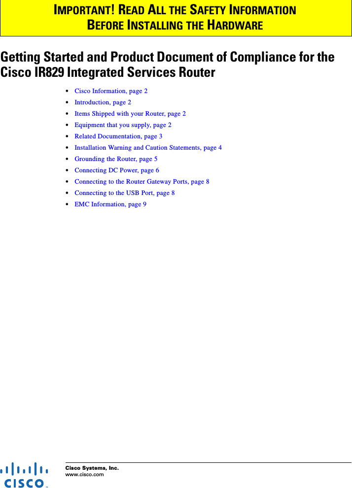
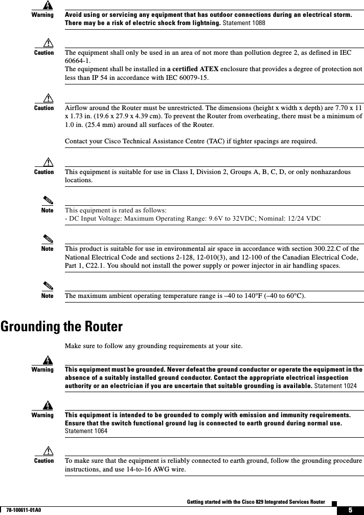
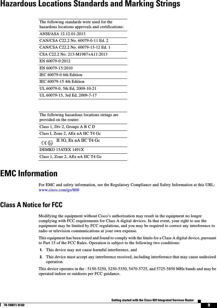
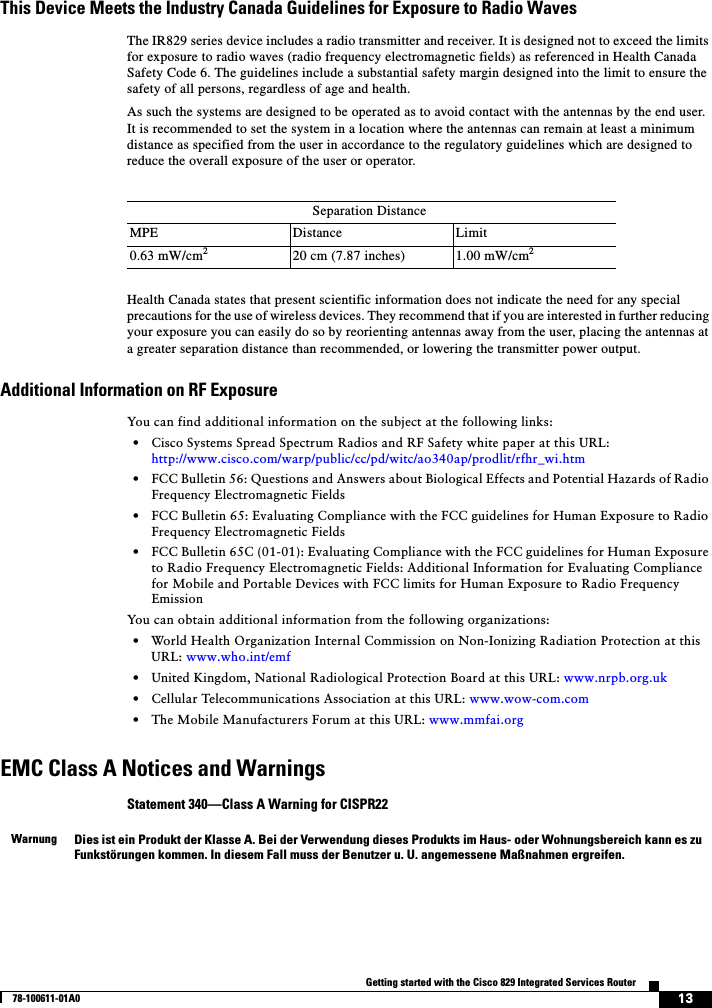
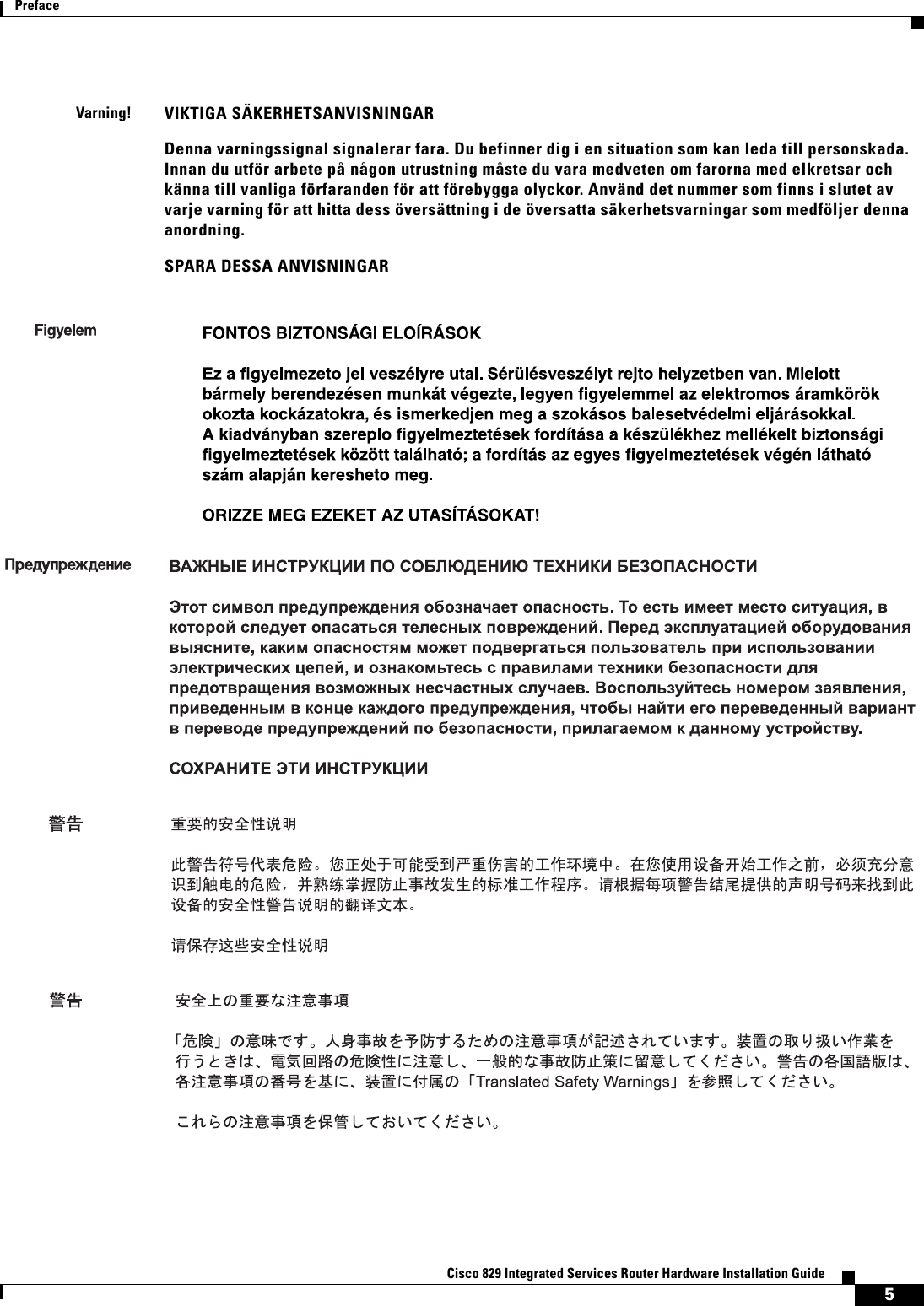
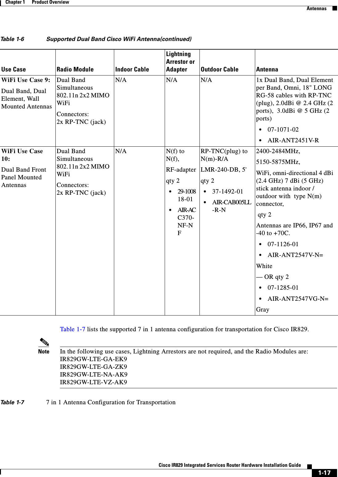
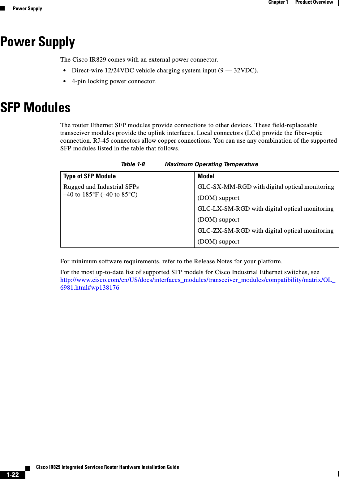
![4-3Cisco IR829 Integrated Services Router Hardware Installation GuideChapter 4 Initial Configuration Setup Command FacilityAsync0 unassigned YES unset up down Async1 unassigned YES unset up down GigabitEthernet2 unassigned NO unset up up Cellular0 unassigned NO unset down down Cellular1 unassigned NO unset down down Step 9 Choose one of the available interfaces for connecting the router to the management network.Enter interface name used to connect to themanagement network from the above interface summary: GigabitEthernet0Step 10 Respond to the following prompts as appropriate for your network:Configuring interface GigabitEthernet0:Configure IP on this interface? [yes]: yesUse the 100 Base-TX (RJ-45) connector? [yes]: yesOperate in full-duplex mode? [no]: yesConfigure IP on this interface? [yes]: yes IP address for this interface: 172.1.2.3 Subnet mask for this interface [255.255.0.0] : 255.255.0.0 Class B network is 172.1.0.0, 26 subnet bits; mask is /16The configuration is displayed:The following configuration command script was created:hostname Routerenable secret 5 $1$D5P6$PYx41/lQIASK.HcSbfO5q1enable password xxxxxxline vty 0 4password xxxxxxsnmp-server community public!no ip routing!interface GigabitEthernet0no shutdownspeed 100duplex autoip address 172.16.2.3 255.255.0.0!Step 11 Respond to the following prompts. Enter 2 to save the initial configuration.[0] Go to the IOS command prompt without saving this config.[1] Return back to the setup without saving this config.[2] Save this configuration to nvram and exit.Enter your selection [2]: 2Building configuration...Use the enabled mode 'configure' command to modify this configuration.Press RETURN to get started! RETURNThe user prompt is displayed.Router>Step 12 Verify the initial configuration. See the “Verifying the Initial Configuration” section on page 4-4 for verification procedures.](https://usermanual.wiki/Cisco-Systems/IR829GW-LTE/User-Guide-2736232-Page-56.png)
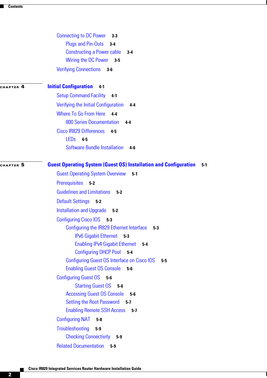
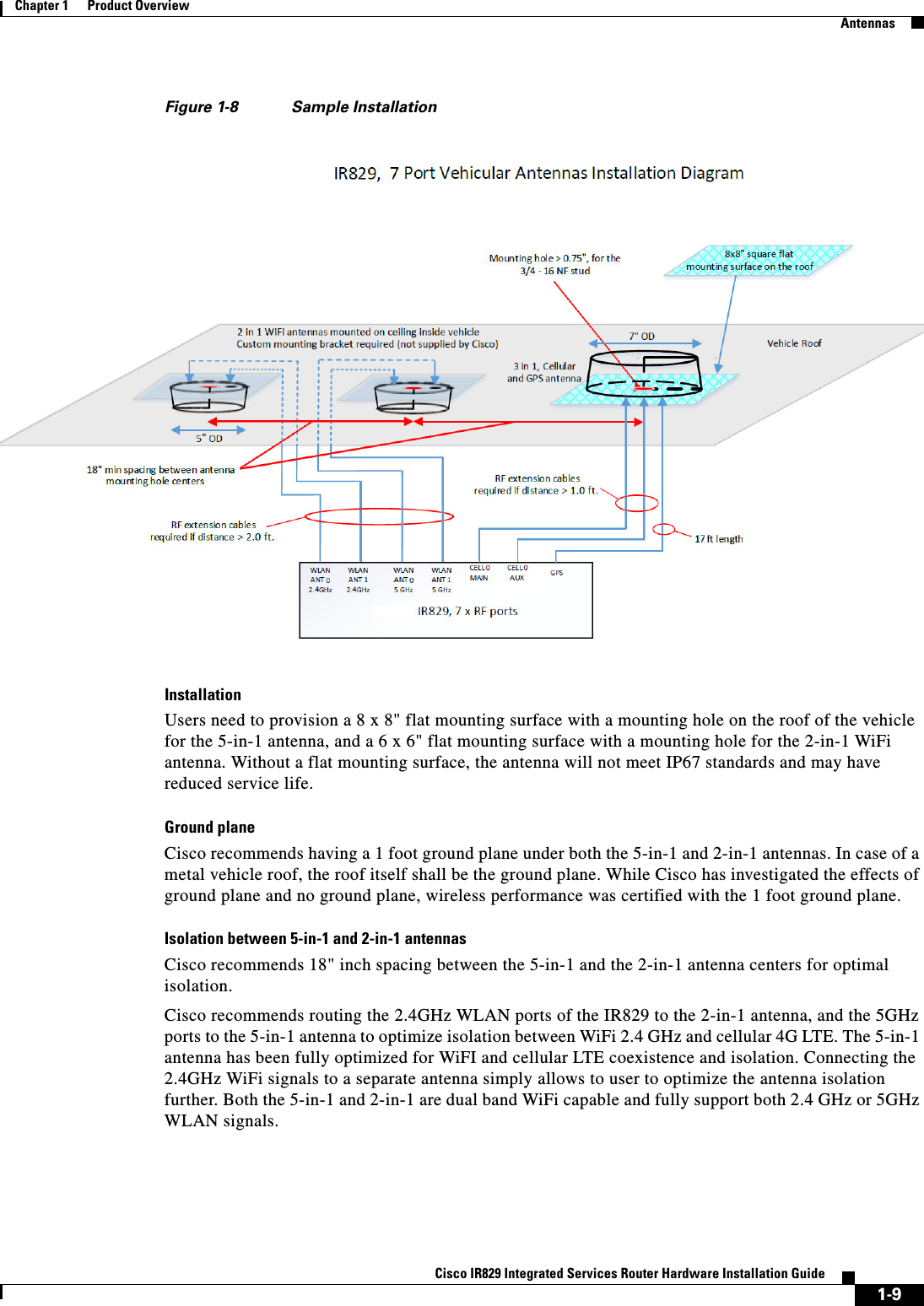
![4-6Cisco IR829 Integrated Services RouterChapter 4 Initial Configuration Cisco IR829 DifferencesIR800#show platform led system System LED: amber, blinkingSummary of the LED status providers: Client Type Status------------------------------ -------- --------GigabitEthernet5 critical OK Note There may be a lag time between the LED indication on the router and what the show led commands return.Software Bundle InstallationThe Cisco IR829 ships with the latest software available with the configuration that was ordered. There should be no reason to have to upgrade unless a failure occurs or you have been instructed to reload all software. Should the need arise, the following steps will assist in performing a bundle installation.Overview:1. Download the bundle to flash memory from a TFTP server.2. Install the bundle from the Command Line Interface3. Save the configuration and reload the router to use the new image.4. Download the 4G firmware upgrade.Example:Step 1 Copy the bundle from a TFTP server to your router.IR800#copy tftp flash Address or name of remote host [223.255.254.254]? your ip address hereSource filename [path to file/ir800-universalk9-bundle.SSA.156-0.3.T]? Destination filename [ir800-universalk9-bundle.SSA.156-0.3.T]? Accessing tftp://223.255.254.254/tachen/ir800-universalk9-bundle.SSA.156-0.3.T...Loading tachen/ir800-universalk9-bundle.SSA.156-0.3.T from 223.255.254.254 (via Vlan1): !*Jun 25 18:28:45.685: %ARP-4-NULL_SRC_MAC: NULL MAC address from 99.99.0.1 on wl0!!!!!!!!!!!!!!!!!!!!!!!!!!!!!!!!!!!!!!!!!!!!!!!!!!!!!!!!!!!!!!!!!!!!!!!!!!!!!!!!!!!!!!!!!!!!!!!!!!!!!!!!!!!!!!!!!!!!!!!!!!!!!!!!!!!!!!!!!!!!!!!!!!!!!!!!!!!!!!!!!!!!!!!!!!!!!!!!!!!!!!!!!!!!!!!!!!!!!!!!!!!!!!!!!!!!!!!!!!!!!!!!!!!!!!!!!!!!!!!!!!!!!!!!!!!!!!!!!!!!!!!!!!!!!!!!!!!!!!!!!!!!!!!!!!!!!!!!!!!!!!!!!!!!!!!!!!!!!!!!!!!!!!!!!!!!!!!!!!!!!!!!!!!!!!!!!!!!!!!!!!!!!!!!!!!!!!!!!!!!!!!!!!!!!!!!!!!!!!!!!!!!!!!!!!!!!!!!!!!!!!!!!!!!!!!!!!!!!!!!!!!!!!!!!!!!!!!!!!!!!!!!!!!!!!!!!!!!!!!!!!!!!!!!!!!!!!!!!!!!!!!!!!!!!!!!!!!!!!!!!!!!!!!!!!!!!!!!!!!!!!!!!!!!!!!!!!!!!!!![OK - 143536651 bytes]143536651 bytes copied in 774.390 secs (185354 bytes/sec)Step 2 The bundle download is complete, and now needs to be installed. Perform the bundle install flash: < bundle iOS image name> command.IR800#bundle install flash:ir800-universalk9-bundle.SSA.156-0.3.T Installing bundle image: /ir800-universalk9-bundle.SSA.156-0.3.T........................................................................................... updating Hypervisor image... Sending file modes: C0444 23753557 ir800-hv.srp.SPA.0.28 SRP md5 verification passed!](https://usermanual.wiki/Cisco-Systems/IR829GW-LTE/User-Guide-2736232-Page-59.png)
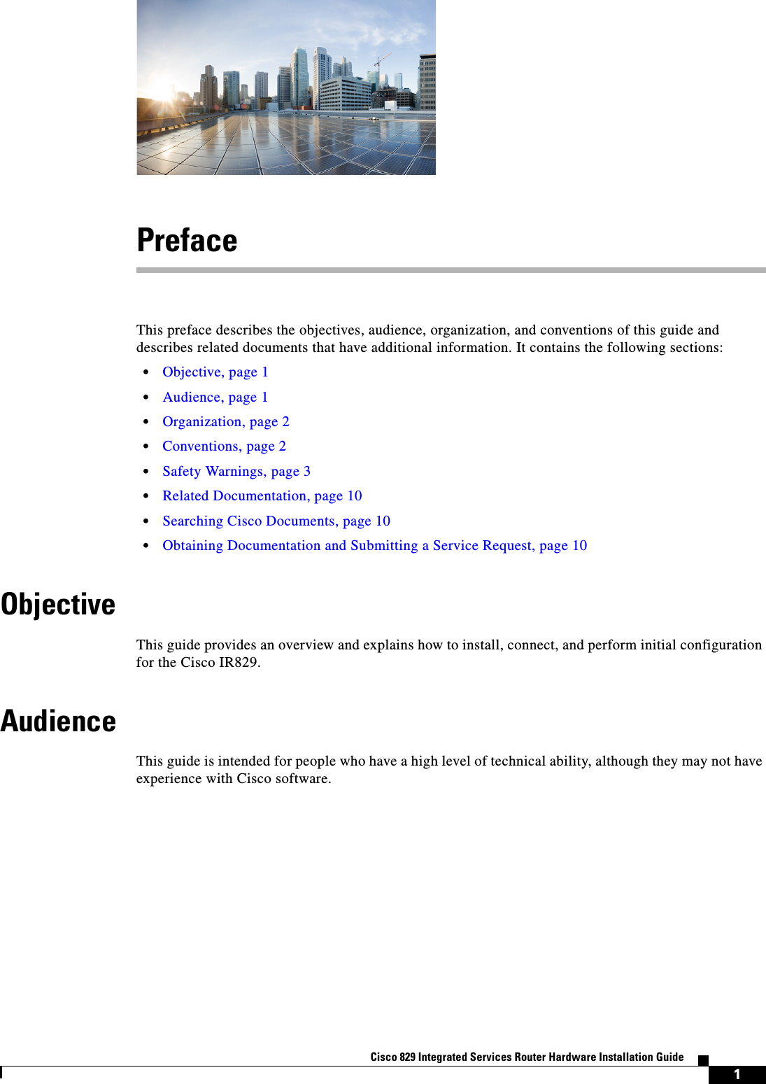
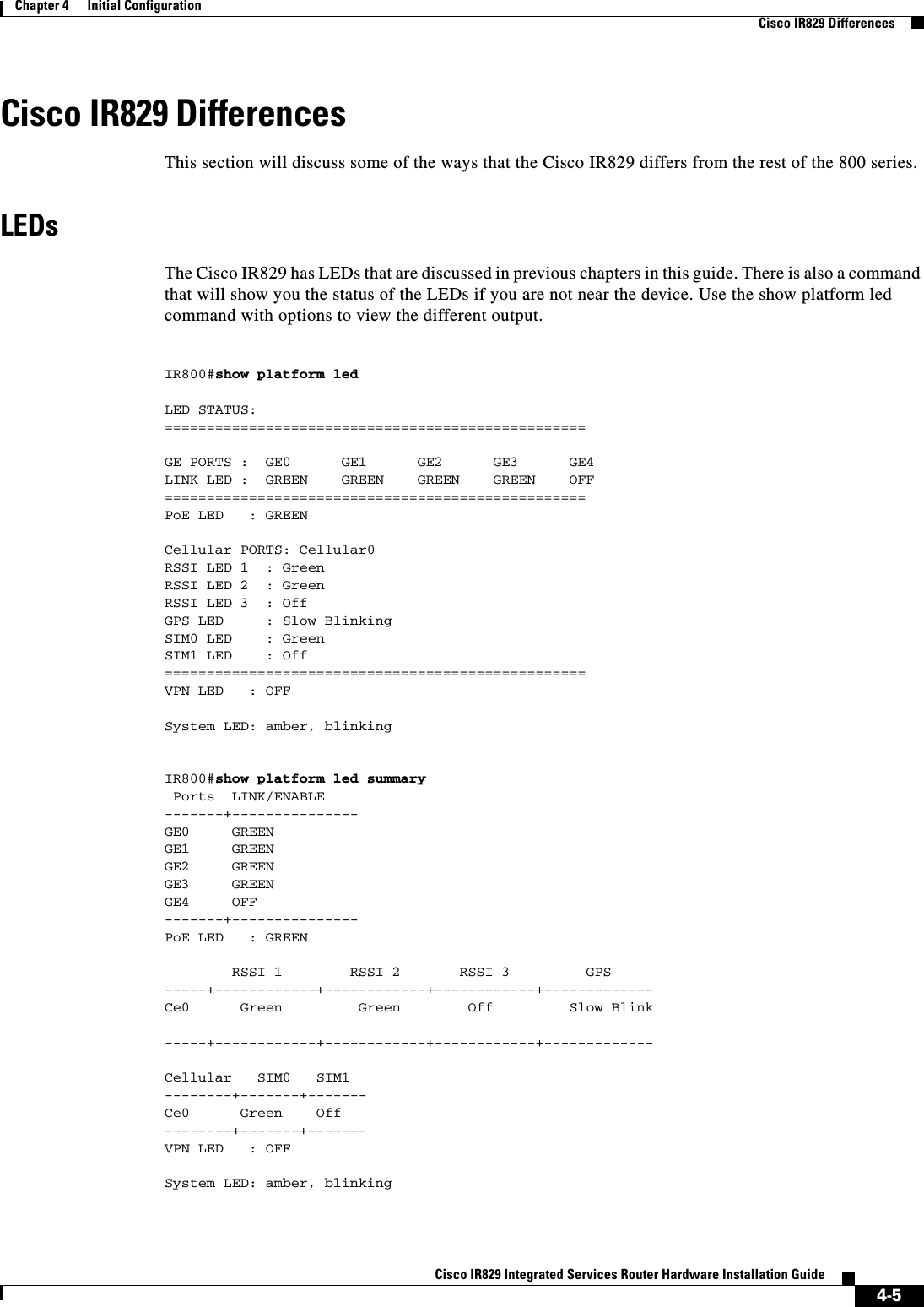
![4-7Cisco IR829 Integrated Services Router Hardware Installation GuideChapter 4 Initial Configuration Cisco IR829 Differencesupdating IOS image... Sending file modes: C0644 61505652 ir800-universalk9-mz.SSA.156-0.3.T IOS md5 verification passed!Done!IR800#*Jun 25 18:51:16.975: %SYS-5-CONFIG_I: Configured from console by bundle install command*Jun 25 18:51:16.975: %IR800_INSTALL-6-SUCCESS_BUNDLE_INSTALL: Successfully installed bundle image.Step 3 Save the configuration and reload the router.IR800#reloadDo you want to reload the internal AP ? [yes/no]: yesSystem configuration has been modified. Save? [yes/no]: yesBuilding configuration... [OK]Proceed with reload? [confirm]press return*Jun 25 19:03:13.685: %SYS-5-RELOAD: Reload requested by console. Reload Reason: Reload Command.Step 4 Download the 4G firmware or AP image. Instructions for uploading firmware are located here:http://www.cisco.com/c/en/us/td/docs/routers/access/interfaces/software/feature/guide/EHWIC-4G-LTESW.htmlSearch for “Upgrading the Modem Firmware”.](https://usermanual.wiki/Cisco-Systems/IR829GW-LTE/User-Guide-2736232-Page-60.png)

![5-7Cisco IR829 Integrated Services Router Hardware Installation GuideChapter 5 Guest Operating System (Guest OS) Installation and Configuration Configuring Guest OSEXAMPLEPoky 9.0 (Yocto Project 1.4 Reference Distro) 1.4 qemux86 ttyS0qemux86 login: rootroot@qemux86:~#Setting the Root PasswordGuest OS does not have a default root password. To set a root password, at the GOS prompt enter the following command.Note You must set a root password before turning on SSH access.EXAMPLEChanging password for user root.New UNIX password:Retype new UNIX password:passwd: all authentication tokens updated successfully.[GOS]#An alternate method for changing the root password is shown in the following example:IR800#iox host exec "resetpw cisco" IR800-GOS-1 Password reset successfully. Enabling Remote SSH AccessBy default, SSH access is disabled to prevent unauthorized access to Guest OS. To enable SSH server on the guest OS:Step 1 Launch the vi editor to edit the sshd_config file: vi /etc/ssh/sshd_configStep 2 Set the PermitRootLogin and PasswordAuthentication parameters to yes. Command Purposetelnet 9.1.2.1 2070 Accesses the Guest OS console. This uses the IP address of the Gigabit Ethernet 5 port. The following is the example result:Command Purpose[GOS] # passwd Runs the following UNIX password script. Enter your desired password at the prompt.](https://usermanual.wiki/Cisco-Systems/IR829GW-LTE/User-Guide-2736232-Page-68.png)
![5-8Cisco IR829 Integrated Services RouterChapter 5 Guest Operating System (Guest OS) Installation and Configuration Configuring NATNote Ensure that the PermitEmptyPasswords parameter is set to no.PermitRootLogin yes PasswordAuthentication yes PermitEmptyPasswords no Step 3 Restart SSHD:[GOS]# /etc/init.d/sshd stopStopping sshd: [ OK ][GOS]# /etc/init.d/sshd startStarting sshd: [ OK ][GOS]#Step 4 From the IOS command line, enter the following:IR800#iox host exec enablessh IR800-GOS-1 ssh enabled successfully. You now have remote SSH access to Guest OS.Configuring NATThe following example configuration uses NAT for Guest OS network connectivity, where: • 9.1.1.0 is the externally reachable subnet. • 9.1.1.131 is the external IP address made available for Guest OS access. • 192.168.1.0 is the private subnet created for Guest OS to Cisco IOS connectivity. This is not directly reachable outside the IR829. • The IP address acquired by Guest OS through IOS local DHCP pool is 192.168.1.2. This address can be obtained using show iox host list details command from IOS.ip dhcp pool gospoolnetwork 192.168.1.0 255.255.255.0default-router 192.168.1.1domain-name utility.comdns-server 9.1.1.1lease 5interface gig 5ip nat insideip address 192.168.1.1 255.255.255.0ipv6 enableno shutdown interface gig 0ip nat outsideip address 9.1.1.5 255.255.255.0no shutdownip nat inside source static 192.168.1.2 9.1.1.131! End of configurationIR800#sh ip nat trans](https://usermanual.wiki/Cisco-Systems/IR829GW-LTE/User-Guide-2736232-Page-69.png)
![5-9Cisco IR829 Integrated Services Router Hardware Installation GuideChapter 5 Guest Operating System (Guest OS) Installation and Configuration TroubleshootingPro Inside global Inside local Outside local Outside globaltcp 9.1.1.131:22 192.168.1.2:22 9.1.1.3:53649 9.1.1.3:53649tcp 9.1.1.131:60100 192.168.1.2:60100 9.1.1.3:22 9.1.1.3:22--- 9.1.1.131 192.168.1.2 --- ---TroubleshootingTo determine common causes of configuration failure, enter the following commands:Checking ConnectivityUse standard Linux tools (for example, ping and traceroute) to check Guest OS connectivity.Related DocumentationFind Cisco 1000 Series Connected Grid Routers product documentation at:www.cisco.com/go/cgr1000-docs. Find Connected Grid Modules for Cisco 1000 Series Connected Grid Routers documentation at:www.cisco.com/go/cg-modulesCommand Purposeifconfig eth0 Checks if Guest OS is assigned an IP address. The following is example output:eth0 Link encap:Ethernet HWaddr 02:00:03:f1:cd:05inet addr:9.1.2.2 Bcast:0.0.0.0 Mask:255.255.255.248UP BROADCAST RUNNING MULTICAST MTU:1500 Metric:1RX packets:2 errors:0 dropped:0 overruns:0 frame:0TX packets:5 errors:0 dropped:0 overruns:0 carrier:0collisions:0 txqueuelen:1000RX bytes:684 (684.0 B) TX bytes:894 (894.0 B)[GOS]# netstat -r Displays the Guest OS route table. The following is example output:Kernel IP routing tableDestination Gateway Genmask Flags MSS Window irtt Ifacedefault 9.1.2.1 0.0.0.0 UG 0 0 0 eth09.1.2.0 * 255.255.255.0 U 0 0 0 eth0[GOS]#show ip arp Verifies that Cisco IOS learned Guest OS ARP mapping.The following is example output:Protocol Address Age (min) Hardware Addr Type InterfaceInternet 9.1.1.1 - 0022.bdef.c562 ARPA GigabitEthernet0Internet 9.1.2.1 - 0022.bdef.c569 ARPA GigabitEthernet5Internet 9.1.2.2 112 0022.bdef.c56d ARPA GigabitEthernet5IR800#](https://usermanual.wiki/Cisco-Systems/IR829GW-LTE/User-Guide-2736232-Page-70.png)