Cisco Systems IR829GW-LTE IR829 Integrated Services Router User Manual
Cisco Systems Inc IR829 Integrated Services Router Users Manual
Users Manual

THE SPECIFICATIONS AND INFORMATION REGARDING THE PRODUCTS IN THIS MANUAL ARE SUBJECT TO CHANGE WITHOUT NOTICE. ALL
STATEMENTS, INFORMATION, AND RECOMMENDATIONS IN THIS MANUAL ARE BELIEVED TO BE ACCURATE BUT ARE PRESENTED WITHOUT
WARRANTY OF ANY KIND, EXPRESS OR IMPLIED. USERS MUST TAKE FULL RESPONSIBILITY FOR THEIR APPLICATION OF ANY PRODUCTS.
THE SOFTWARE LICENSE AND LIMITED WARRANTY FOR THE ACCOMPANYING PRODUCT ARE SET FORTH IN THE INFORMATION PACKET THAT
SHIPPED WITH THE PRODUCT AND ARE INCORPORATED HEREIN BY THIS REFERENCE. IF YOU ARE UNABLE TO LOCATE THE SOFTWARE LICENSE
OR LIMITED WARRANTY, CONTACT YOUR CISCO REPRESENTATIVE FOR A COPY.
The following information is for FCC compliance of Class A devices: This equipment has been tested and found to comply with the limits for a Class A digital device, pursuant
to part 15 of the FCC rules. These limits are designed to provide reasonable protection against harmful interference when the equipment is operated in a commercial
environment. This equipment generates, uses, and can radiate radio-frequency energy and, if not installed and used in accordance with the instruction manual, may cause
harmful interference to radio communications. Operation of this equipment in a residential area is likely to cause harmful interference, in which case users will be required
to correct the interference at their own expense.
The following information is for FCC compliance of Class B devices: This equipment has been tested and found to comply with the limits for a Class B digital device, pursuant
to part 15 of the FCC rules. These limits are designed to provide reasonable protection against harmful interference in a residential installation. This equipment generates,
uses and can radiate radio frequency energy and, if not installed and used in accordance with the instructions, may cause harmful interference to radio communications.
However, there is no guarantee that interference will not occur in a particular installation. If the equipment causes interference to radio or television reception, which can be
determined by turning the equipment off and on, users are encouraged to try to correct the interference by using one or more of the following measures:
• Reorient or relocate the receiving antenna.
• Increase the separation between the equipment and receiver.
• Connect the equipment into an outlet on a circuit different from that to which the receiver is connected.
• Consult the dealer or an experienced radio/TV technician for help.
Modifications to this product not authorized by Cisco could void the FCC approval and negate your authority to operate the product.
The Cisco implementation of TCP header compression is an adaptation of a program developed by the University of California, Berkeley (UCB) as part of UCB’s public
domain version of the UNIX operating system. All rights reserved. Copyright © 1981, Regents of the University of California.
NOTWITHSTANDING ANY OTHER WARRANTY HEREIN, ALL DOCUMENT FILES AND SOFTWARE OF THESE SUPPLIERS ARE PROVIDED “AS IS” WITH
ALL FAULTS. CISCO AND THE ABOVE-NAMED SUPPLIERS DISCLAIM ALL WARRANTIES, EXPRESSED OR IMPLIED, INCLUDING, WITHOUT
LIMITATION, THOSE OF MERCHANTABILITY, FITNESS FOR A PARTICULAR PURPOSE AND NONINFRINGEMENT OR ARISING FROM A COURSE OF
DEALING, USAGE, OR TRADE PRACTICE.
IN NO EVENT SHALL CISCO OR ITS SUPPLIERS BE LIABLE FOR ANY INDIRECT, SPECIAL, CONSEQUENTIAL, OR INCIDENTAL DAMAGES, INCLUDING,
WITHOUT LIMITATION, LOST PROFITS OR LOSS OR DAMAGE TO DATA ARISING OUT OF THE USE OR INABILITY TO USE THIS MANUAL, EVEN IF CISCO
OR ITS SUPPLIERS HAVE BEEN ADVISED OF THE POSSIBILITY OF SUCH DAMAGES.
Cisco and the Cisco logo are trademarks or registered trademarks of Cisco and/or its affiliates in the U.S. and other countries. To view a list of Cisco trademarks, go to this
URL: www.cisco.com/go/trademarks. Third-party trademarks mentioned are the property of their respective owners. The use of the word partner does not imply a partnership
relationship between Cisco and any other company. (1110R)
Any Internet Protocol (IP) addresses and phone numbers used in this document are not intended to be actual addresses and phone numbers. Any examples, command display
output, network topology diagrams, and other figures included in the document are shown for illustrative purposes only. Any use of actual IP addresses or phone numbers in
illustrative content is unintentional and coincidental.
Cisco IR829 Integrated Services Router Hardware Installation Guide
© 2015 Cisco Systems, Inc. All rights reserved.

1
Cisco IR829 Integrated Services Router Hardware Installation Guide
CONTENTS
Cisco IR829 Integrated Services Router Hardware Installation Guide
1
CHAPTER
1Product Overview 1-1
General Description 1-1
LEDs 1-4
Memory 1-6
SKU Information 1-6
Hardware Features 1-6
Platform Features for Cisco IR829 1-7
Reset Button 1-8
Antennas 1-8
Antennas and Installation Scenarios 1-8
Supported Cisco Antennas and Cables 1-10
Power Supply 1-22
SFP Modules 1-22
CHAPTER
2Installing the Router 2-1
Equipment, Tools, and Connections 2-2
Items Shipped with your Router 2-2
Additional Items 2-2
Ethernet Devices 2-3
Installing the Router 2-3
Warnings 2-3
Accessing the SIM Cards 2-3
Installing Antennas 2-5
Mounting on a Wall, Table, or Other Flat Surface 2-5
Installing the Router Ground Connection 2-7
CHAPTER
3Connecting the Router 3-1
Preparing to Connect the Router 3-1
Preventing Damage to the Router 3-1
Connecting a PC, Server, or Workstation 3-2
Connecting a Terminal or PC to the Console Port 3-3

Contents
2
Cisco IR829 Integrated Services Router Hardware Installation Guide
Connecting to DC Power 3-3
Plugs and Pin-Outs 3-4
Constructing a Power cable 3-4
Wiring the DC Power 3-5
Verifying Connections 3-6
CHAPTER
4Initial Configuration 4-1
Setup Command Facility 4-1
Verifying the Initial Configuration 4-4
Where To Go From Here 4-4
800 Series Documentation 4-4
Cisco IR829 Differences 4-5
LEDs 4-5
Software Bundle Installation 4-6
CHAPTER
5Guest Operating System (Guest OS) Installation and Configuration 5-1
Guest Operating System Overview 5-1
Prerequisites 5-2
Guidelines and Limitations 5-2
Default Settings 5-2
Installation and Upgrade 5-2
Configuring Cisco IOS 5-3
Configuring the IR829 Ethernet Interface 5-3
IPv6 Gigabit Ethernet 5-3
Enabling IPv4 Gigabit Ethernet 5-4
Configuring DHCP Pool 5-4
Configuring Guest OS Interface on Cisco IOS 5-5
Enabling Guest OS Console 5-6
Configuring Guest OS 5-6
Starting Guest OS 5-6
Accessing Guest OS Console 5-6
Setting the Root Password 5-7
Enabling Remote SSH Access 5-7
Configuring NAT 5-8
Troubleshooting 5-9
Checking Connectivity 5-9
Related Documentation 5-9


Contents
4
Cisco IR829 Integrated Services Router Hardware Installation Guide

1
Cisco 829 Integrated Services Router Hardware Installation Guide
Preface
This preface describes the objectives, audience, organization, and conventions of this guide and
describes related documents that have additional information. It contains the following sections:
• Objective, page 1
• Audience, page 1
• Organization, page 2
• Conventions, page 2
• Safety Warnings, page 3
• Related Documentation, page 10
• Searching Cisco Documents, page 10
• Obtaining Documentation and Submitting a Service Request, page 10
Objective
This guide provides an overview and explains how to install, connect, and perform initial configuration
for the Cisco IR829.
Audience
This guide is intended for people who have a high level of technical ability, although they may not have
experience with Cisco software.

2
Cisco 829 Integrated Services Router Hardware Installation Guide
Preface
Organization
This guide is organized into the following chapters.
Conventions
This section describes the conventions used in this guide.
Note Means reader take note. Notes contain helpful suggestions or references to additional information and
material.
Caution This symbol means reader be careful. In this situation, you might do something that could result in
equipment damage or loss of data.
Tip Means the following information will help you solve a problem. The tip information might not be
troubleshooting or even an action, but could be useful information.
Chapter Name Description
Chapter 1 Chapter 1, “Product Overview” Describes the router models and the
hardware features available.
Chapter 2 Chapter 2, “Installing the Router” Lists the items shipped with the router, the
equipment and tools necessary for
installing the router, the safety warnings
and guidelines, and the procedures for
installing the router.
Chapter 3 Chapter 3, “Connecting the Router” Describes typical connections for the
router, procedures for connecting the
router to various devices, and how to
verify the connections.
Chapter 4 Chapter 4, “Initial Configuration” Provides the procedures for initially
configuring the router settings.
Chapter 5 Chapter 5, “Guest Operating System
(Guest OS) Installation and
Configuration”
Provides details Guest for Operating
System (Guest OS) installation for the
Cisco IR829.
Chapter 6 Chapter 6, “Technical Specifications” Provides the router, port, and cabling
specifications.

3
Cisco 829 Integrated Services Router Hardware Installation Guide
Preface
Safety Warnings
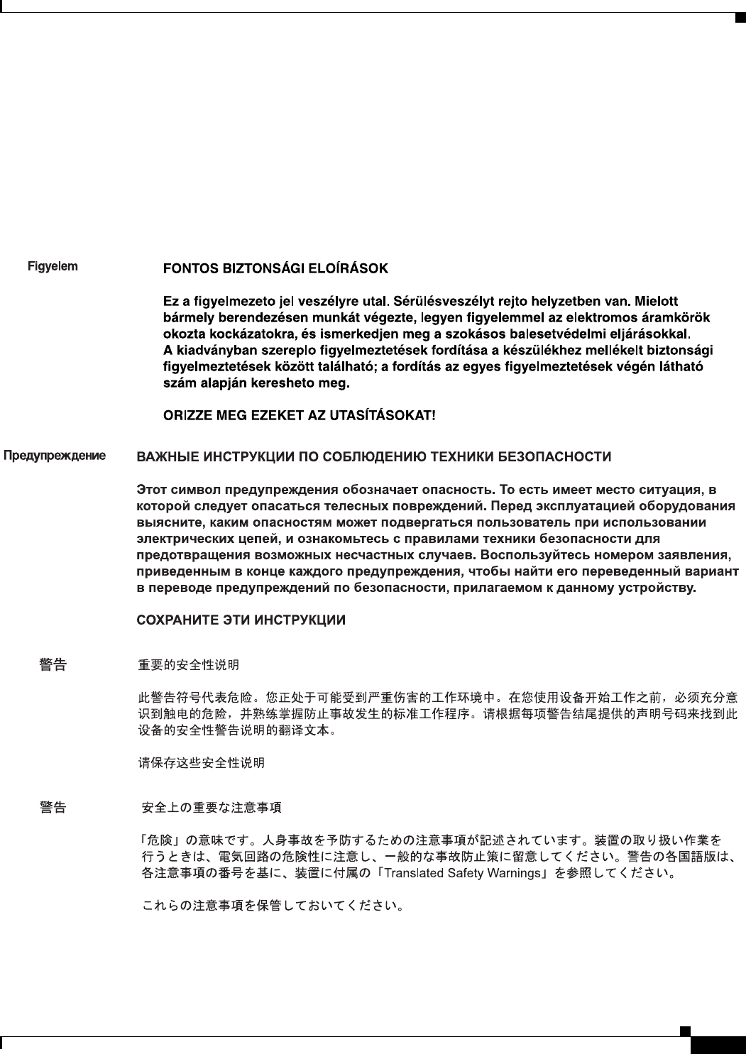
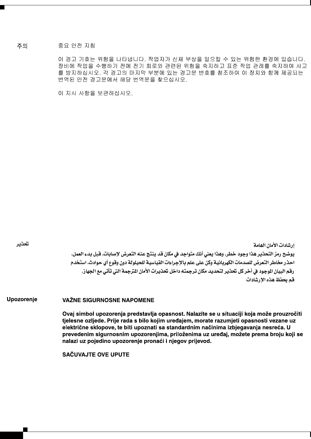
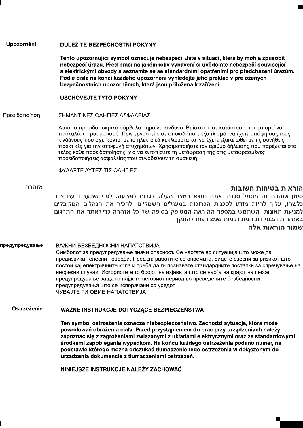
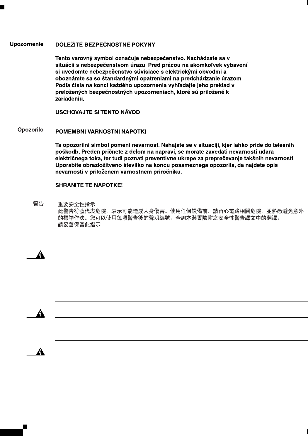
Warning
IMPORTANT SAFETY INSTRUCTIONS
This warning symbol means danger. You are in a situation that could cause bodily injury. Before you
work on any equipment, be aware of the hazards involved with electrical circuitry and be familiar
with standard practices for preventing accidents. Use the statement number provided at the end of
each warning to locate its translation in the translated safety warnings that accompanied this
device.
Statement 1071
SAVE THESE INSTRUCTIONS
Waarschuwing
BELANGRIJKE VEILIGHEIDSINSTRUCTIES
Dit waarschuwingssymbool betekent gevaar. U verkeert in een situatie die lichamelijk letsel kan
veroorzaken. Voordat u aan enige apparatuur gaat werken, dient u zich bewust te zijn van de bij
elektrische schakelingen betrokken risico's en dient u op de hoogte te zijn van de standaard
praktijken om ongelukken te voorkomen. Gebruik het nummer van de verklaring onderaan de
waarschuwing als u een vertaling van de waarschuwing die bij het apparaat wordt geleverd, wilt
raadplegen.
BEWAAR DEZE INSTRUCTIES
Varoitus
TÄRKEITÄ TURVALLISUUSOHJEITA
Tämä varoitusmerkki merkitsee vaaraa. Tilanne voi aiheuttaa ruumiillisia vammoja. Ennen kuin
käsittelet laitteistoa, huomioi sähköpiirien käsittelemiseen liittyvät riskit ja tutustu
onnettomuuksien yleisiin ehkäisytapoihin. Turvallisuusvaroitusten käännökset löytyvät laitteen
mukana toimitettujen käännettyjen turvallisuusvaroitusten joukosta varoitusten lopussa näkyvien
lausuntonumeroiden avulla.
SÄILYTÄ NÄMÄ OHJEET
Attention
IMPORTANTES INFORMATIONS DE SÉCURITÉ
Ce symbole d'avertissement indique un danger. Vous vous trouvez dans une situation pouvant
entraîner des blessures ou des dommages corporels. Avant de travailler sur un équipement, soyez
conscient des dangers liés aux circuits électriques et familiarisez-vous avec les procédures
couramment utilisées pour éviter les accidents. Pour prendre connaissance des traductions des
avertissements figurant dans les consignes de sécurité traduites qui accompagnent cet appareil,
référez-vous au numéro de l'instruction situé à la fin de chaque avertissement.
CONSERVEZ CES INFORMATIONS

4
Cisco 829 Integrated Services Router Hardware Installation Guide
Preface
Warnung
WICHTIGE SICHERHEITSHINWEISE
Dieses Warnsymbol bedeutet Gefahr. Sie befinden sich in einer Situation, die zu Verletzungen führen
kann. Machen Sie sich vor der Arbeit mit Geräten mit den Gefahren elektrischer Schaltungen und
den üblichen Verfahren zur Vorbeugung vor Unfällen vertraut. Suchen Sie mit der am Ende jeder
Warnung angegebenen Anweisungsnummer nach der jeweiligen Übersetzung in den übersetzten
Sicherheitshinweisen, die zusammen mit diesem Gerät ausgeliefert wurden.
BEWAHREN SIE DIESE HINWEISE GUT AUF.
Avvertenza
IMPORTANTI ISTRUZIONI SULLA SICUREZZA
Questo simbolo di avvertenza indica un pericolo. La situazione potrebbe causare infortuni alle
persone. Prima di intervenire su qualsiasi apparecchiatura, occorre essere al corrente dei pericoli
relativi ai circuiti elettrici e conoscere le procedure standard per la prevenzione di incidenti.
Utilizzare il numero di istruzione presente alla fine di ciascuna avvertenza per individuare le
traduzioni delle avvertenze riportate in questo documento.
CONSERVARE QUESTE ISTRUZIONI
Advarsel
VIKTIGE SIKKERHETSINSTRUKSJONER
Dette advarselssymbolet betyr fare. Du er i en situasjon som kan føre til skade på person. Før du
begynner å arbeide med noe av utstyret, må du være oppmerksom på farene forbundet med
elektriske kretser, og kjenne til standardprosedyrer for å forhindre ulykker. Bruk nummeret i slutten
av hver advarsel for å finne oversettelsen i de oversatte sikkerhetsadvarslene som fulgte med denne
enheten.
TA VARE PÅ DISSE INSTRUKSJONENE
Aviso
INSTRUÇÕES IMPORTANTES DE SEGURANÇA
Este símbolo de aviso significa perigo. Você está em uma situação que poderá ser causadora de
lesões corporais. Antes de iniciar a utilização de qualquer equipamento, tenha conhecimento dos
perigos envolvidos no manuseio de circuitos elétricos e familiarize-se com as práticas habituais de
prevenção de acidentes. Utilize o número da instrução fornecido ao final de cada aviso para
localizar sua tradução nos avisos de segurança traduzidos que acompanham este dispositivo.
GUARDE ESTAS INSTRUÇÕES
¡Advertencia!
INSTRUCCIONES IMPORTANTES DE SEGURIDAD
Este símbolo de aviso indica peligro. Existe riesgo para su integridad física. Antes de manipular
cualquier equipo, considere los riesgos de la corriente eléctrica y familiarícese con los
procedimientos estándar de prevención de accidentes. Al final de cada advertencia encontrará el
número que le ayudará a encontrar el texto traducido en el apartado de traducciones que acompaña
a este dispositivo.
GUARDE ESTAS INSTRUCCIONES
5
Cisco 829 Integrated Services Router Hardware Installation Guide
Preface
Varning!
VIKTIGA SÄKERHETSANVISNINGAR
Denna varningssignal signalerar fara. Du befinner dig i en situation som kan leda till personskada.
Innan du utför arbete på någon utrustning måste du vara medveten om farorna med elkretsar och
känna till vanliga förfaranden för att förebygga olyckor. Använd det nummer som finns i slutet av
varje varning för att hitta dess översättning i de översatta säkerhetsvarningar som medföljer denna
anordning.
SPARA DESSA ANVISNINGAR
6
Cisco 829 Integrated Services Router Hardware Installation Guide
Preface
Aviso
INSTRUÇÕES IMPORTANTES DE SEGURANÇA
Este símbolo de aviso significa perigo. Você se encontra em uma situação em que há risco de lesões
corporais. Antes de trabalhar com qualquer equipamento, esteja ciente dos riscos que envolvem os
circuitos elétricos e familiarize-se com as práticas padrão de prevenção de acidentes. Use o
número da declaração fornecido ao final de cada aviso para localizar sua tradução nos avisos de
segurança traduzidos que acompanham o dispositivo.
GUARDE ESTAS INSTRUÇÕES
Advarsel
VIGTIGE SIKKERHEDSANVISNINGER
Dette advarselssymbol betyder fare. Du befinder dig i en situation med risiko for
legemesbeskadigelse. Før du begynder arbejde på udstyr, skal du være opmærksom på de
involverede risici, der er ved elektriske kredsløb, og du skal sætte dig ind i standardprocedurer til
undgåelse af ulykker. Brug erklæringsnummeret efter hver advarsel for at finde oversættelsen i de
oversatte advarsler, der fulgte med denne enhed.
GEM DISSE ANVISNINGER
7
Cisco 829 Integrated Services Router Hardware Installation Guide
Preface
8
Cisco 829 Integrated Services Router Hardware Installation Guide
Preface
Warning
When installing the product, please use the provided or designated connection cables/power
cables/AC adaptors. Using any other cables/adaptors could cause a malfunction or a fire. Electrical
Appliance and Material Safety Law prohibits the use of UL-certified cables (that have the “UL” shown
on the code) for any other electrical devices than products designated by CISCO. The use of cables
that are certified by Electrical Appliance and Material Safety Law (that have “PSE” shown on the
code) is not limited to CISCO-designated products.
Statement 371
Warning
Read the wall-mounting instructions carefully before beginning installation. Failure to use the
correct hardware or to follow the correct procedures could result in a hazardous situation to people
and damage to the system.
Statement 378
Warning
To avoid electric shock, do not connect safety extra-low voltage (SELV) circuits to telephone-network
voltage (TNV) circuits. LAN ports contain SELV circuits, and WAN ports contain TNV circuits. Some
LAN and WAN ports both use RJ-45 connectors. Use caution when connecting cables.
Statement 1021

9
Cisco 829 Integrated Services Router Hardware Installation Guide
Preface
Warning
T
his equipment must be grounded. Never defeat the ground conductor or operate the equipment in the
absence of a suitably installed ground conductor. Contact the appropriate electrical inspection
authority or an electrician if you are uncertain that suitable grounding is available
. Statement 1024
Warning
If the symbol of suitability with an overlaid cross appears above a port, you must not connect the port
to a public network that follows the European Union standards. Connecting the port to this type of
public network can cause severe personal injury or can damage the unit.
Statement 1031
Warning
Connect the unit only to DC power source that complies with the safety extra-low voltage (SELV)
requirements in IEC 60950 based safety standards.
Statement 1033
Warning
When installing or replacing the unit, the ground connection must always be made first and
disconnected last.
Statement 1046
Warning
Do not locate the antenna near overhead power lines or other electric light or power circuits, or
where it can come into contact with such circuits. When installing the antenna, take extreme care
not to come into contact with such circuits, because they may cause serious injury or death. For
proper installation and grounding of the antenna, please refer to national and local codes (for
example, U.S.:NFPA 70, National Electrical Code, Article 810, Canada: Canadian Electrical Code,
Section 54).
Statement 1052
Warning
No user-serviceable parts inside. Do not open.
Statement 1073
Warning
Installation of the equipment must comply with local and national electrical codes.
Statement 1074
Warning
Only trained and qualified personnel should be allowed to install, replace, or service this equipment.
Statement 1030
Warning
Read the installation instructions before connecting the system to the power source.
Statement 1004
Warning
Ultimate disposal of this product should be handled according to all national laws and regulations.
Statement 1040
Warning
The covers are an integral part of the safety design of the product. Do not operate the unit without the
covers installed.
Statement 1077

10
Cisco 829 Integrated Services Router Hardware Installation Guide
Preface
Warning
Hot surface.
Statement 1079
Related Documentation
• Regulatory Compliance and Safety Information for Cisco 800 Series and SOHO Series Routers
• Cisco IOS Release Notes
• Cisco 800 Series Integrated Services Routers Software Configuration Guide.
Searching Cisco Documents
To search an HTML document using a web browser, press Ctrl-F (Windows) or Cmd-F (Apple). In most
browsers, the option to search whole words only, invoke case sensitivity, or search forward and backward
is also available.
To search a PDF document in Adobe Reader, use the basic Find toolbar (Ctrl-F) or the Full Reader
Search window (Shift-Ctrl-F). Use the Find toolbar to find words or phrases within a specific document.
Use the Full Reader Search window to search multiple PDF files simultaneously and to change case
sensitivity and other options. Adobe Reader’s online help has more information about how to search PDF
documents.
Obtaining Documentation and Submitting a Service Request
For information on obtaining documentation, submitting a service request, and gathering additional
information, see the monthly What’s New in Cisco Product Documentation, which also lists all new and
revised Cisco technical documentation, at:
http://www.cisco.com/en/US/docs/general/whatsnew/whatsnew.html
Subscribe to the What’s New in Cisco Product Documentation as a Really Simple Syndication (RSS) feed
and set content to be delivered directly to your desktop using a reader application. The RSS feeds are a free
service and Cisco currently supports RSS Ve r s io n 2.0.
CHAPTER
1-1
Cisco IR829 Integrated Services Router Hardware Installation Guide
1
Product Overview
This chapter provides an overview of the features available for the Cisco IR829 Integrated Services
Routers (ISRs) and contains the following sections:
• General Description, page 1-1
• SKU Information, page 1-6
• Hardware Features, page 1-6
Note For compliance and safety information, see Regulatory Compliance and Safety Information for Cisco
800 Series and SOHO Series Routers.
General Description
The Cisco IR829 Integrated Services Router, part of the Cisco Integrated Services Routers Generation 2
(ISR G2) Family, is designed as a next generation ruggedized fixed form factor router. It is a a small-form
factor cellular router targeting mobile/vehicle applications and includes WiFi to provide connectivity in
non-carpeted IT spaces, Industrials, Utilities, Transportation, Infrastructure, Industrial M2M
application, asset monitoring, Smart Grid, and Utility Application.
Figure 1-1 shows the IR829.
Figure 1-1 Cisco IR829 Integrated Services Router
1-2
Cisco IR829 Integrated Services Router Hardware Installation Guide
Chapter 1 Product Overview
General Description
Figure 1-2 shows the front panel details of the Cisco IR829.
Figure 1-2 Cisco IR829 Front Panel
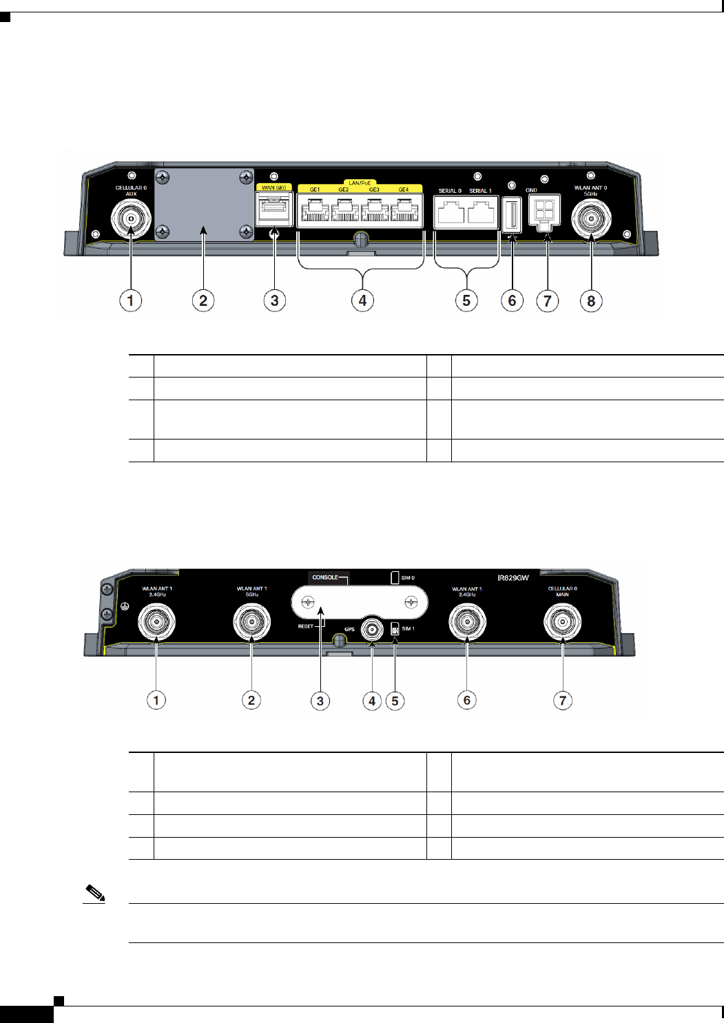
Figure 1-3 shows the back panels details of the Cisco IR829.
Figure 1-3 Cisco IR829 Back Panel
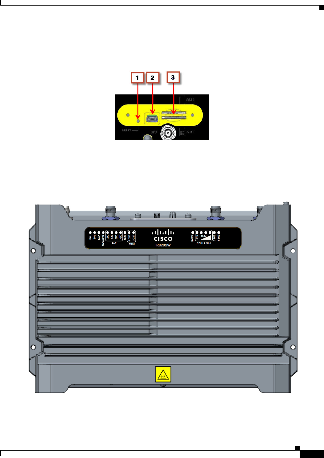
Note Behind the SIM Door Assembly, there is a reset switch, Mini USB Debug connection, and Dual SIM
slots. See Figure 1-4 for details
1CELLULAR 0 AUX 5Serial Ports
2Limited Modularity Slot 6USB-A Port
3Gigabit WAN 7Power Input, Battery, and Ignition connector.
Refer to the DC Power section for pin-outs.
4Gigabit LAN/PoE 8WLAN ANT0 5GHz
1WLAN ANT 0 2.4GHz 5SIM connection 1 (SIM connection 0 is
above)
2WLAN ANT 1 5GHz 6WLAN ANT 1 2.4GHz
3SIM Door Assembly 7CELLULAR 0 MAIN
4GPS SMA
1-4
Cisco IR829 Integrated Services Router Hardware Installation Guide
Chapter 1 Product Overview
General Description
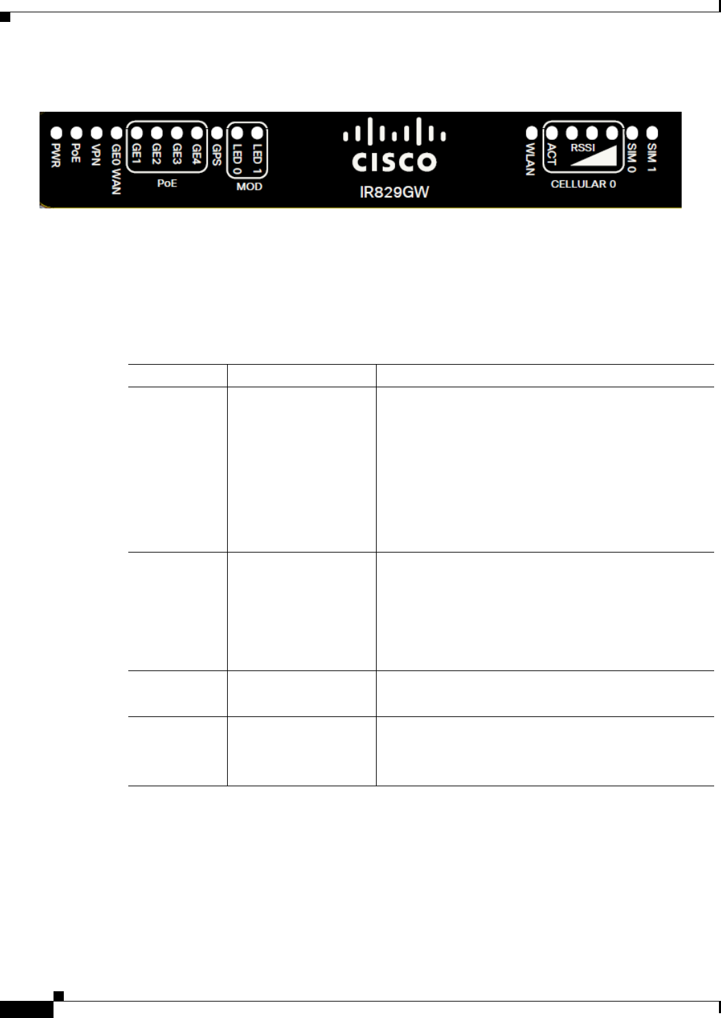
Figure 1-6 Cisco IR829 LED Detail
The following section shows a detailed description of the LEDs.
LEDs
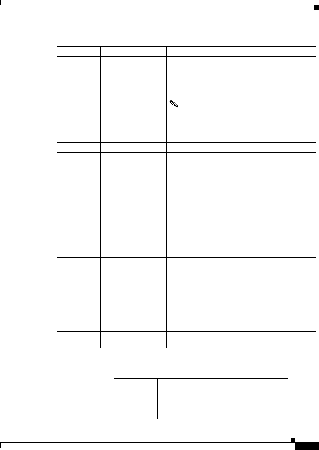
The following table describes the LEDs for the Cisco IR829.
Ta b l e 1-1 LED Descriptions
LED Activity Description
PWR Power Status Off — No power
Green Steady on — Normal operation
Green Flashing — Boot up phase or in ROM Monitor
mode
Yellow Steady on — System shutdown due to under or
over voltage conditions
Yellow Flashing — System has an error, but has network
connectivity
POE POE Power Supply
Status
Off — No -54V PoE power supply detected or no PoE
board installed
Green Steady on — 53.5V POE power supply good and
all powered port operating normally
Yellow Steady on — 53.5V POE power supply good, but
one or more POE ports has a fault.
VPN VPN Off — No VPN tunnel
Steady on — At least one VPN tunnel is up
GE0 WAN Link Status Off — No link
Steady on — Link is up
Blink — Transmitting and Receiving data
1-5
Cisco IR829 Integrated Services Router Hardware Installation Guide
Chapter 1 Product Overview
General Description
Figure 1-7 RSSI LED
GPS GPS Status Off — GPS not configured
On — GPS configured
Slow Flash — GPS Acquiring in Standalone GPS
Fast Flash — GPS Acquiring in Assisted GPS
Note Slow Flash is defined as the LED will be on for
0.25 seconds and off for 0.75 seconds.
Fast Flash s defined as the LED will be on for
0.25 seconds and off for 0.25 seconds.
MOD
Ethernet LAN
Switch Ports
GE1-GE4]
Single LED per
Port
Link Status/POE Status Off — No link
Green Steady on — Link is up
Green Blink — Transmitting and Receiving data
Yellow — POE Fault, implies no link
WLAN 2.4GHz
5GHz
Off — Radio is down (no SSID configured)
Flashing Green — Bootloader, IOS Ethernet
Initialization, IOS Start Up after system initialization.
Green to Red to Yellow — Discovery/Join process.
Rapid Flashing Green — Joined to a controller
Steady Green — One wireless client is associated.
CELLULAR0/
CELLULAR1
ACT Off — Module not powered on
On — Module is powered on and connected but not
transmitting or receiving
Slow Blink — Module is powered on and searching for
connection
Fast Blink — Module is transmitting or receiving.
CELLULAR0/
CELLULAR1
RSSI The RSSI LEDs are a 3 LED bar graph to indicate signal
strength. Their functionality is described in the RSSI LED
figure below.
SIM0/SIM1 Sim cards Off — No USIM
Green — USIM installed and active
Table 1-1 LED Descriptions (continued)
LED Activity Description
RSSI RSSI (2) RSSI (1) RSSI (0)
Green Green Green/Yellow
<110dBm Off Off Off
-110 — 90dBm Off Off On - Yellow

1-6
Cisco IR829 Integrated Services Router Hardware Installation Guide
Chapter 1 Product Overview
SKU Information
Memory
The Cisco IR829 uses flash memory and main memory. The flash memory contains the Cisco IOS
software image and the boot flash contains the ROMMON boot code. All memory components are
factory default and not upgradeable by the end user.
Table 1-2 shows the memory allocation.
Ta b l e 1-2 Cisco IR829 Memory
SKU Information
Table 1-1 lists the different SKUs available for the Cisco ISRs. All SKUs support external antenna.
Hardware Features
This section provides an overview of the following hardware features for the Cisco IR829.
• Platform Features for Cisco IR829, page 1-7
• Antennas, page 1-8
-90 — 75dBm Off Off On - Green
-75 — 60dBm Off On - Green On - Green
>60dBm On - Green On - Green On - Green
RSSI RSSI (2) RSSI (1) RSSI (0)
Memory Capacity
DDR 2GB
Boot ROM 16MB
System Flash 4GB
Ta b l e 1-3 Supported SKUs for Cisco IR829s
SKU ID Description
IR829GW-LTE-VZ-
AK9
C829 Hardened WAN GE 4G LTE secure platform multi-mode Verizon
LTE/DoRa with 802.11n, FCC compliant
IR829GW-LTE-NA-
AK9
C829 Hardened WAN GE 4G LTE secure platform multi-mode ATT and
Canada LTE/HSPA+ with 802.11n, FCC compliant
IR829GW-LTE-GA-
EK9
C829 Hardened WAN GE 4G LTE secure platform multi-mode Global
(Europe) LTE/HSPA+ with 802.11n, ETSI Compliant
IR829GW-LTE-GA-
ZK9
C829 Hardened WAN GE 4G LTE secure platform multi-mode Global
(Australia) LTE/HSPA+ with 802.11n, Australia Compliant

1-7
Cisco IR829 Integrated Services Router Hardware Installation Guide
Chapter 1 Product Overview
Hardware Features
• Reset Button, page 1-8
• Supported Cisco Antennas and Cables, page 1-10
• Power Supply, page 1-22
Platform Features for Cisco IR829
The following lists the hardware platform features for the Cisco IR829.
• Intel Atom Dual-Core Rangeley CPU, 1250 MHz
• 2GB DDR3 memory capacity
• 64MB SPI BIOS NOR flash
• 8GB (4GB usable) “eMMC” bulk storage flash
• 4-port GE LAN switch, optional PoE 802.3at (30W max)
• WAN 1 GE SFP
• WWAN /WLAN
–
mini PCIe slots for 3G/4G/LTE modems, dual SIM
–
Single 802.11 a/b/n WiFi radio
• Optional Limited Modularity (BYOI) slot'
• One RJ45 RS232 port
• One RJ45 RS232/RS485 Serial port
• One USB 2.0 Type A external port
• One mini USB connector
• Lithium Ion battery backed-up RTC
• External Reset/Recovery Push Button
• External Power
–
Direct-wire 12/24VDC vehicle charging system input (9 — 32VDC)
–
4-pin locking power connector
• External GPS SMA Connector
• Six External TNC/RP-TNC connectors (depends on the configuration) for connection to WWAN
/WLAN internal modules
• Class A EMC compliance
• RoHS6 compliance
• Mechanical
–
Fanless operation
–
Form-factor with no cable cover = 11.00” x 7.70” x 1.73” (WDH)
–
Horizontal, Vertical, wall, floor, cabinet-mount and shelf-mount

1-8
Cisco IR829 Integrated Services Router Hardware Installation Guide
Chapter 1 Product Overview
Antennas
Reset Button
The Reset button resets the router configuration to the default configuration set by the factory. To restore
the router configuration to the default configuration set by the factory, use a standard size #1 paper clip
with wire gauge 0.033 inch or smaller and simultaneously press the reset button while applying power
to the router.
Note The rear cover must be removed to expose the reset switch.
Antennas
The IR829 has 4 x Wi-Fi antennas (2.4GHz & 5GHz) + 2 antennas for cellular RP-TNC bulkhead
connectors.
Standard antennas are:
• Two multiband swivel-mount dipole antennae (ANT-4G-DP-IN-TNC) and one extender
(4G-AE010-R) are included with all the IR829s.
• WLAN: Three Cisco Multiband Swivel-Mount Dipole Antennae. (AIR-ANTM2050D-R) are
included for all IR829 SKUs that have WLAN functionality.
For detailed information about Cisco Antennas, please refer to the following guides:
Connected Grid Antennas Installation Guide:
http://www.cisco.com/c/en/us/td/docs/routers/connectedgrid/antennas/installing/cg_antenna_install_gu
ide.html
Antennas for the Cisco 800 Series Routers:
http://www.cisco.com/c/en/us/support/routers/800-series-routers/products-installation-guides-list.html
Antennas and Installation Scenarios
Note Before choosing your antenna type and installation scenario, read through the following information.
Coexistence of radio standards:
When operating and planning installation of products with WiFi, 4G LTE, and GPS wireless standards
coexisting on the IR829 platform, the user needs to provision greater than 15dB isolation between the
WiFi and LTE antennas at all frequencies of 4G LTE and WiFI operation for minimum impact to
performance.
Ideally, isolation should be 20-25dB or more. Specifically, users should not install 4G LTE dipoles and
WiFi dipoles on the chassis at the same time, since doing so would generally result in less than 15dB
isolation and may have a strong impact on performance depending on frequency bands in question.
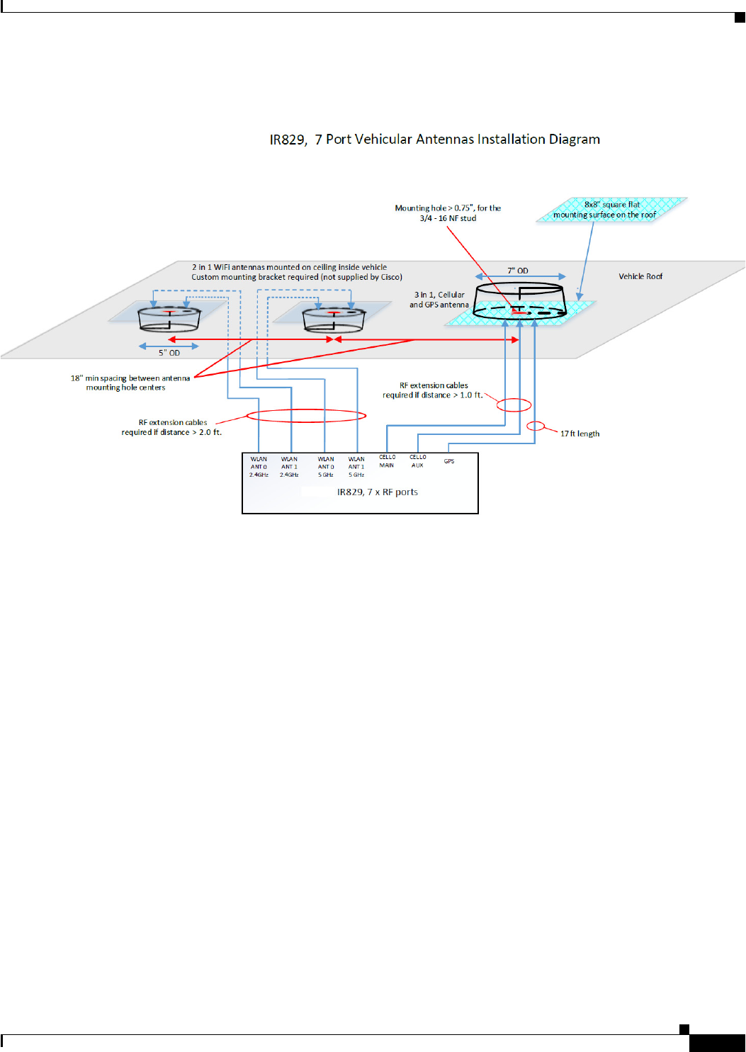
Vehicular 5-in-1 and 2-in-1 installation and deployment notes
In the section that follows, the 5-in-1 antenna refers to ANT-5-4G2WL2G1-O, and 2-in-1 antenna refers
to ANT-2-WLAN-D-O.
1-9
Cisco IR829 Integrated Services Router Hardware Installation Guide
Chapter 1 Product Overview
Antennas
Figure 1-8 Sample Installation
Installation
Users need to provision a 8 x 8" flat mounting surface with a mounting hole on the roof of the vehicle
for the 5-in-1 antenna, and a 6 x 6" flat mounting surface with a mounting hole for the 2-in-1 WiFi
antenna. Without a flat mounting surface, the antenna will not meet IP67 standards and may have
reduced service life.
Ground plane
Cisco recommends having a 1 foot ground plane under both the 5-in-1 and 2-in-1 antennas. In case of a
metal vehicle roof, the roof itself shall be the ground plane. While Cisco has investigated the effects of
ground plane and no ground plane, wireless performance was certified with the 1 foot ground plane.
Isolation between 5-in-1 and 2-in-1 antennas
Cisco recommends 18" inch spacing between the 5-in-1 and the 2-in-1 antenna centers for optimal
isolation.
Cisco recommends routing the 2.4GHz WLAN ports of the IR829 to the 2-in-1 antenna, and the 5GHz
ports to the 5-in-1 antenna to optimize isolation between WiFi 2.4 GHz and cellular 4G LTE. The 5-in-1
antenna has been fully optimized for WiFI and cellular LTE coexistence and isolation. Connecting the
2.4GHz WiFi signals to a separate antenna simply allows to user to optimize the antenna isolation
further. Both the 5-in-1 and 2-in-1 are dual band WiFi capable and fully support both 2.4 GHz or 5GHz
WLAN signals.

1-10
Cisco IR829 Integrated Services Router Hardware Installation Guide
Chapter 1 Product Overview
Antennas
MIMO ports on 5-in-1 and 2-in-1
Cellular and WLAN ports on the 5-in-1 and 2-in-1 antennas support MIMO technology. MIMO brings
significant improvements in throughput and robustness of the wireless link in fading channels. Users
choosing to connect only one wireless port on MIMO capable products are giving up significant wireless
performance in both throughput and robustness of the link.
• The individual 4G antenna cables on the 5-in-1 antenna can be connected to either cellular port of
IR829. There is no one-to-one assignment requirement.
• The individual WLAN antenna cables on the 5-in-1 antenna and the 2-in-1 antenna can be connected
to any WLAN port of IR829. There is no one to one assignment requirement.
The following section shows some examples of different installation scenarios.
Supported Cisco Antennas and Cables
Table 1-4 lists the supported 4G/LTE Radio Modules/Cables/Antennas for Cisco IR829.
Ta b l e 1-4 4G/LTE Radio Modules/Cables/Antennas
Use Case Radio Module Indoor Cable
Lightning
Arrestor or
Adapter Outdoor Cable Antenna
4G/LTE Case 1:
1' 2', 5', 10', 15' or 20'
cable to mast mounted
antenna, Stick Omni
or Directional Flat
Panel antenna
IR829GW-LTE
-GA-EK9
IR829GW-LTE
-GA-ZK9
IR829GW-LTE
-NA-AK9
IR829GW-LTE
-VZ-AK9
2x TNC(f)
None
Router located in
outdoor protective
enclosure
None RA-TNC(m) to
N(m),
LMR-400-DB,
20', qty 2
• 37-1378-01
• "CAB-L400-2
0-TNC-N
2x 4G Omni Stick,
Standard Perf, 10”
2dBi, 1x N(f) each
• 07-1171-01
• ANT-4G-OMNI-O
UT-N
1x 4G Panel Antenna,
2x N(f) each
• 07-1172-01
• ANT-4G-PNL-OUT
-N
4G/LTE Case 2: IR829GW-LTE
-GA-EK9
IR829GW-LTE
-GA-ZK9
IR829GW-LTE
-NA-AK9
IR829GW-LTE
-VZ-AK9
2x TNC(f)
R/A-TNC(m) to
N(m),
LMR-240-FR/CMR,
2’, qty 2
• 37-100707-01
Note Not
available
from Cisco
1x 4G Panel Antenna,
2x N(f) each
• 07-1172-01
• ANT-4G-PNL-OUT
-N

1-11
Cisco IR829 Integrated Services Router Hardware Installation Guide
Chapter 1 Product Overview
Antennas
R/A-TNC(m) to
N(m),
LMR-240-FR/CMR,
1', qty 2
• 37-100705-01
Note Not
available
from Cisco
R/A-TNC(m) to
N(m),
LMR-240-FR/CMR,
5', qty 2
• 37-100717-01
Note Not
available
from Cisco
R/A-TNC(m) to
N(m),
LMR-240-FR/CMR,
10', qty 2
• 37-100754-01
Note Not
available
from Cisco
R/A-TNC(m) to
N(m),
LMR-240-FR/CMR,
15', qty 2
• 37-100757-01
Note Not
available
from Cisco
R/A-TNC(m) to
N(m),
LMR-240-FR/CMR,
20', qty 2
• 37-100758-01
Note Not
available
from Cisco
Table 1-4 4G/LTE Radio Modules/Cables/Antennas
Use Case Radio Module Indoor Cable
Lightning
Arrestor or
Adapter Outdoor Cable Antenna

1-12
Cisco IR829 Integrated Services Router Hardware Installation Guide
Chapter 1 Product Overview
Antennas
4G/LTE Case 3:
Front Panel Swivel
Mount 4G-LTE
dipoles
IR829GW-LTE
-GA-EK9
IR829GW-LTE
-GA-ZK9
IR829GW-LTE
-NA-AK9
IR829GW-LTE
-VZ-AK9
2x TNC(f)
None
—OR
qty 2x
PID: 4G-AE010-R
CPN: 07-1144-01
10ft extension base
for TNC dipole
antennas
—OR
qty 2x
PID: 4G-AE015-R
CPN: 07-1145-01
15ft extension base
for TNC dipole
antennas
None None Qty 2 x
4G Indoor Swivel
Mount Dipole, 0 dBi,
TNC(m), white
• 07-1174-01
• ANT-4G-DP-IN-TN
C
4G/LTE Case 4:
Front Panel Swivel
Mount 4G-LTE
dipoles
IR829GW-LTE
-GA-EK9
IR829GW-LTE
-GA-ZK9
IR829GW-LTE
-NA-AK9
IR829GW-LTE
-VZ-AK9
2x TNC(f)
None
—OR
qty 2x
PID: 4G-AE010-R
CPN: 07-1144-01
10ft extension base
for TNC dipole
antennas
—OR
qty 2x
PID: 4G-AE015-R
CPN: 07-1145-01
15ft extension base
for TNC dipole
antennas
None None Qty 2 x
4G Indoor Swivel
Mount Dipole, 0 dBi,
TNC(m), black
• 07-1137-01
• 4G-LTE-ANTM-D
Table 1-4 4G/LTE Radio Modules/Cables/Antennas
Use Case Radio Module Indoor Cable
Lightning
Arrestor or
Adapter Outdoor Cable Antenna

1-13
Cisco IR829 Integrated Services Router Hardware Installation Guide
Chapter 1 Product Overview
Antennas
4G/LTE Case 5:
2x ceiling mount
4G-LTE antennas
IR829GW-LTE
-GA-EK9
IR829GW-LTE
-GA-ZK9
IR829GW-LTE
-NA-AK9
IR829GW-LTE
-VZ-AK9
2x TNC(f)
None None None Qty 2 x
4G Indoor
omni-directional
Ceiling Mount 2 dBi,
• 07-1121-01
• 4G-ANTM-OM-C
M
— OR
Qty 2 x
4G Dipole Ceiling
Mount 2 dBi
• 07-1174-01
• ANT-4G-DP-IP-TN
C
GPS Case 1:
GPS Antenna with
Integrated 15' coax
cable, Mounted to top
of Utility Cabinet
Roof
• SMA(f), qty 1
GPS Antenna.
Need one with
integrated coax cable
and SMA(m)
connector, 17ft,
outdoor, IP67
qty 1
• 07-1183-01
• GPS-ACT-ANTM-S
MA=
Table 1-4 4G/LTE Radio Modules/Cables/Antennas
Use Case Radio Module Indoor Cable
Lightning
Arrestor or
Adapter Outdoor Cable Antenna

1-14
Cisco IR829 Integrated Services Router Hardware Installation Guide
Chapter 1 Product Overview
Antennas
Table 1-5 lists the supported Single Band Cisco WiFi antenna for the Cisco IR829.
Ta b l e 1-5 Supported Single Band Cisco WiFi Antenna
Use Case Radio Module Indoor Cable
Lightning
Arrestor or
Adapter Outdoor Cable Antenna
WiFi Use Case 2:
Single Band, Front
Panel Mounted
Antennas
Dual Band
Simultaneous
802.11n 2x2 MIMO
WiFi
Connectors:
4x RP-TNC (jack)
N/A N/A N/A 2x Single Band, Swivel
Mount Omni,
RP-TNC(plug), 2.2dBi @ 2.4
GHz
07-1056-02
AIR-ANT4941
2x Single Band, Swivel
Mount Omni,
RP-TNC(plug), 3.5dBi @ 5
GHz
• 07-1055-02
• AIR-ANT5135
WiFi Use Case 3:
Single Band,
Single Element,
Ceiling Mounted
Antennas
Dual Band
Simultaneous
802.11n 2x2 MIMO
WiFi
Connectors:
4x RP-TNC (jack)
None
— OR
RP-TNC (jack)
to RP-TNC
(plug), Outdoor
rated, Plenum
rated, 0.195"
O.D. cable,
5' long
• 37-1067-01
• AIR-CAB005
PL-R
N/A N/A 2x Single Band, Ceiling
Mount Omni, 36” LONG
RG-58 cable with RP-TNC
(plug), 5.2dBi @ 2.4 GHz
• 74-1868-01
• AIR-ANT1728
2x Single Band, Ceiling
Mount Omni, 36" LONG
RG-58 cable with RP-TNC
(plug), 5.2dBi @ 5 GHz
• 74-3733-01
• AIR-ANT5160V-R
WiFi Use Case 4:
2.4 GHz, Dual
Element, 5 GHz
Single Element,
Ceiling Mounted
Antennas
Dual Band
Simultaneous
802.11n 2x2 MIMO
WiFi
Connectors: 4x
RP-TNC (jack)
None
— OR
RP-TNC(jack) to
RP-TNC(plug),
Outdoor rated,
Plenum rated,
0.195” O.D.
cable, 5’ long
37-1067-01
AIR-CAB005PL
-R
N/A N/A 1x Single Band, Ceiling
Mount Omni, Dual Element,
36" LONG RG-58 cable with
RP-TNC, 2.0dBi @ 2.4 GHz
• 800-33316-01
• AIR-ANT24020V-R
2x Single Band, Ceiling
Mount Omni, 36" LONG
RG-58 cable with RP-TNC
(plug), 5.2dBi @ 5 GHz
• 74-3733-01
• AIR-ANT5160V-R

1-15
Cisco IR829 Integrated Services Router Hardware Installation Guide
Chapter 1 Product Overview
Antennas
WiFi Use Case 5:
Single Band, Dual
Element, Wall
Mounted Antennas
Dual Band
Simultaneous
802.11n 2x2 MIMO
WiFi
Connectors:
4x RP-TNC (jack)
None None
— OR
RP-TNC
lightning
arrestor,
qty 4
• 74-3722-
01
• AIR-AC
C245L
A-R
None
— OR
RP-TNC(plug) to
RP-TNC(jack)
LMR-400-DB, 5'
qty 4
• 37-0766-01
• AIR-CAB005LL
-R
— OR
RP-TNC(plug) to
RP-TNC(jack)
LMR-400-DB, 20'
qty 4
• 72-2760-02
• AIR-CAB020LL
-R
— OR
RP-TNC(plug) to
RP-TNC(jack)
LMR-400-DB, 50'
qty 4
• 72-2761-02
• AIR-CAB050LL
-R
— OR
RP-TNC(plug) to
RP-TNC(jack)
LMR-600-DB,
100'
qty 4
• 72-2766-02
• AIR-CAB100U
LL-R
1x Single Band, Dual
Element, Wall Mount Patch,
18" LONG RG-58 cable with
RP-TNC, 6.5dBi @ 2.4 GHz
• 800-27066-01
• AIR-ANT2465P-R
1x Single Band, Dual
Element, Wall Mount Omni,
18" LONG RG-58 cables
with RP-TNC, 4.5dBi @ 5
GHz (INDOOR ONLY)
• 800-25716-06
• AIR-ANT5145V-R
— OR
1x Single Band, Dual
Element, Wall Mount Patch,
18" LONG RG-58 cables
with RP-TNC, 7.0dBi @ 5
GHz (INDOOR/OUTDOOR)
• 800-25718-05
• AIR-ANT5170P-R
Table 1-5 Supported Single Band Cisco WiFi Antenna(continued)
Use Case Radio Module Indoor Cable
Lightning
Arrestor or
Adapter Outdoor Cable Antenna

1-16
Cisco IR829 Integrated Services Router Hardware Installation Guide
Chapter 1 Product Overview
Antennas
Table 1-6 lists the supported Dual Band Cisco WiFi antenna for Cisco IR829.
WiFi Use Case 7:
Single Band, Dual
Element, Wall
Mounted Patch,
Indoor/ Outdoor
Antennas
Dual Band
Simultaneous
802.11n 2x2 MIMO
WiFi
Connectors:
4x RP-TNC (jack)
N(f) to
N(f),
RF-adapter
qty 4
• 29-1008
18-01
• AIR-AC
C370-
NF-N
F
RP-TNC(plug) to
N(m)-R/A
LMR-240-DB, 5'
qty 4
• 37-1492-01
• AIR-CAB005LL
-R-N
1x Single Band, Dual
Element, Wall Mount Patch,
18" LONG RG-58 cable with
N(m), 13dBi @ 2.4 GHz
• 07-1193-01
• AIR-ANT2413P2M-N
1x Single Band, Dual
Element, Wall Mount Patch,
18" LONG RG-58 cable with
N(m), 14dBi @ 5 GHz
• 07-1192-01
• AIR-ANT5114P2M-N
Table 1-5 Supported Single Band Cisco WiFi Antenna(continued)
Use Case Radio Module Indoor Cable
Lightning
Arrestor or
Adapter Outdoor Cable Antenna
Ta b l e 1-6 Supported Dual Band Cisco WiFi Antenna
Use Case Radio Module Indoor Cable
Lightning
Arrestor or
Adapter Outdoor Cable Antenna
WiFi Use Case 8:
Dual Band Front
Panel Mounted
Antennas
Dual Band
Simultaneous
802.11n 2x2 MIMO
WiFi
Connectors:
2x RP-TNC (jack)
N/A N/A N/A 2x Dual Band, Swivel Mount
Omni, RP-TNC(plug), 2dBi
@ 2.4 GHz, 4dBi @ 5 GHz
• 07-1146-01
• AIR-ANT2524DB-R

1-17
Cisco IR829 Integrated Services Router Hardware Installation Guide
Chapter 1 Product Overview
Antennas
Table 1-7 lists the supported 7 in 1 antenna configuration for transportation for Cisco IR829.
Note In the following use cases, Lightning Arrestors are not required, and the Radio Modules are:
IR829GW-LTE-GA-EK9
IR829GW-LTE-GA-ZK9
IR829GW-LTE-NA-AK9
IR829GW-LTE-VZ-AK9
Ta b l e 1-7 7 in 1 Antenna Configuration for Transportation
WiFi Use Case 9:
Dual Band, Dual
Element, Wall
Mounted Antennas
Dual Band
Simultaneous
802.11n 2x2 MIMO
WiFi
Connectors:
2x RP-TNC (jack)
N/A N/A N/A 1x Dual Band, Dual Element
per Band, Omni, 18" LONG
RG-58 cables with RP-TNC
(plug), 2.0dBi @ 2.4 GHz (2
ports), 3.0dBi @ 5 GHz (2
ports)
• 07-1071-02
• AIR-ANT2451V-R
WiFi Use Case
10:
Dual Band Front
Panel Mounted
Antennas
Dual Band
Simultaneous
802.11n 2x2 MIMO
WiFi
Connectors:
2x RP-TNC (jack)
N/A N(f) to
N(f),
RF-adapter
qty 2
• 29-1008
18-01
• AIR-AC
C370-
NF-N
F
RP-TNC(plug) to
N(m)-R/A
LMR-240-DB, 5'
qty 2
• 37-1492-01
• AIR-CAB005LL
-R-N
2400-2484MHz,
5150-5875MHz,
WiFi, omni-directional 4 dBi
(2.4 GHz) 7 dBi (5 GHz)
stick antenna indoor /
outdoor with type N(m)
connector,
qty 2
Antennas are IP66, IP67 and
-40 to +70C.
• 07-1126-01
• AIR-ANT2547V-N=
White
— OR qty 2
• 07-1285-01
• AIR-ANT2547VG-N=
Gray
Table 1-6 Supported Dual Band Cisco WiFi Antenna(continued)
Use Case Radio Module Indoor Cable
Lightning
Arrestor or
Adapter Outdoor Cable Antenna

1-18
Cisco IR829 Integrated Services Router Hardware Installation Guide
Chapter 1 Product Overview
Antennas

1-19
Cisco IR829 Integrated Services Router Hardware Installation Guide
Chapter 1 Product Overview
Antennas
Use Case Extension Cable Antenna
Transportation Use Case 1:
7 x RF ports, with the IR829 deployed
in a transportation application.
(Default Configuration)
Quinta 5-in-1 antenna AND a WiFi
2-in-1 antenna to utilize all 7 ports.
The 5-in1 Quinta antenna and the 2-in1
WiFi antennas need to be separated 18"
between mounting hole centers of the
two antennas.
No extension cables are required if the
IR829 is located within ~1.0ft of 5-in-1
antenna, and ~2.0ft of WiFi 2-in-1
antenna.
If these conditions are not met, this
deployment requires the following
extension cables:
Cellular extension cables (2 ports)
Qty 2X LMR-400-DB TNC(m)-R/A -
TNC(f), 5ft
• 4G-CAB-LMR400-5
• 37-100842-01
— OR
Qty 2X LMR-400-DB TNC(m)-R/A -
TNC(f), 10ft
• G-CAB-LMR400-10
• 37-100843-01
— OR
Qty 2X LMR-400-LLPL
plenum / indoor only
TNC(m)-R/A - TNC(f), 20ft
• 4G-CAB-ULL-20
• 37-1401-01
— AND
Quinta 5 element 5-in-1 transportation
antenna, black radome color, 2x 4G
cellular, 2x dual band WiFi, 1xGPS
• ANT-5-4G2WL2G1-O
• 07-100261-01
Has the following integrated cables:
qty 2 x cellular, LMR-195, 2ft long,
TNC(m)
qty 2 x WiFi, 2ft long, LMR-195
RPTNC (plug)
qty 1 x GPS, RG-174, 17ft long,
SMA(m)
— AND
WiFi 2-in-1 2 element 2 in 1
transportation antenna, black radome
color, 2x dual band WiFi
• ANT-2-WLAN-D-O
• 07-100265-01
Has the following integrated cables:
qty 2 x WiFi, 3ft long, LMR-240
RPTNC(plug)

1-20
Cisco IR829 Integrated Services Router Hardware Installation Guide
Chapter 1 Product Overview
Antennas
Transportation Use Case 1
Continued:
WiFi 2.4 GHz / 5GHz extension cables
(4 ports, can mix and match lengths per
installation requirements if needed)
Qty 4x LMR-400-DB RPTNC(plug) -
STR RPTNC(jack) - STR, 5ft
• AIR-CAB005LL-R
• 37-0766-01
— OR
Qty 4x LMR-400-DB RPTNC(plug)-R/A
RPTNC(jack)-STR, 10ft
• CAB-L400-10-R
• 37-100844-01
— OR
Qty 4x LMR-400-DB RPTNC(plug)-STR
RPTNC(jack)-STR, 20ft
• AIR-CAB020LL-R
• 72-2760-02
— AND
GPS port
No extension cable required, 5-in-1
antenna comes with integrated active
GPS antenna with 17ft cable.
Use Case Extension Cable Antenna

1-21
Cisco IR829 Integrated Services Router Hardware Installation Guide
Chapter 1 Product Overview
Antennas
Transportation Use Case 2:
7 x RF ports, with the IR829 deployed
in a transportation application.
(Alternate Configuration, can be used in
case the application calls for the WiFi
antennas to be separate from the LTE
antenna for example. a ceiling mount
WLAN).
This case describes a Tercia 3-in-1
transportation antenna (which covers
MIMO cellular and GPS) together with
qty 2 x 2-in-1 WiFi antennas.
Note A CUSTOM CEILING
MOUNT BRACKET IS
REQUIRED FOR THE 2-in-1
antenna if installed in a ceiling
mount configuration (NOT
SUPPLIED BY CISCO)
No extension cables are required if the
IR829 unit is located within ~1.0ft of
3-in-1 antenna, and ~2.0ft of WiFi 2-in-1
antenna.
If these conditions are not met, this
deployment requires the following
extension cables:
Cellular extension cables:
(2 ports)
Qty 2X LMR-400-DB TNC(m)-R/A -
TNC(f), 5ft
• 4G-CAB-LMR400-5
• 37-100842-01
— OR
Qty 2X LMR-400-DB TNC(m)-R/A -
TNC(f), 10ft
• 4G-CAB-LMR400-10
• 37-100843-01
— OR
Qty 2X LMR-400-LLPL plenum / indoor
only
TNC(m)-R/A - TNC(f), 20ft
• 4G-CAB-ULL-20
• 37-1401-01
— AND
WiFi 2.4 GHz / 5GHz extension cables (4
ports, can mix and match lengths per
installation requirements if needed)
Qty 4x LMR-400-DB RPTNC(plug) -
STR RPTNC(jack) - STR, 5ft
• AIR-CAB005LL-R
• 37-0766-01
— OR
Qty 4x LMR-400-DB RPTNC(plug)-R/A
RPTNC(jack)-STR, 10ft
• CAB-L400-10-R
• 37-100844-01
— AND
GPS port - No extension cable required,
3-in-1 antenna comes with integrated
active GPS antenna with 17ft cable.
Tercia 3 element 3-in-1 transportation
antenna, black radome color, 2x 4G
cellular, 1xGPS
• ANT-3-4G2G1-O
• 07-100263-01
Has the following integrated cables:
qty 2 x cellular, LMR-195, 2ft long,
TNC(m)
qty 1 x GPS, RG-174, 17ft long,
SMA(m)
— AND
QTY 2 of 2-in-1 antennas
WiFi 2-in-1 2 element 2 in 1
transportation antenna, black radome
color, 2x dual band WiFi
• ANT-2-WLAN-D-O
• 07-100265-01
Has the following integrated cables:
qty 2 x WiFi, 3ft long, LMR-240
RPTNC (plug)
Note A CUSTOM CEILING
MOUNT BRACKET IS
REQUIRED FOR THE 2-in-1
antenna if installed in a ceiling
mount configuration (NOT
SUPPLIED BY CISCO)
Use Case Extension Cable Antenna

1-22
Cisco IR829 Integrated Services Router Hardware Installation Guide
Chapter 1 Product Overview
Power Supply
Power Supply
The Cisco IR829 comes with an external power connector.
• Direct-wire 12/24VDC vehicle charging system input (9 — 32VDC).
• 4-pin locking power connector.
SFP Modules
The router Ethernet SFP modules provide connections to other devices. These field-replaceable
transceiver modules provide the uplink interfaces. Local connectors (LCs) provide the fiber-optic
connection. RJ-45 connectors allow copper connections. You can use any combination of the supported
SFP modules listed in the table that follows.
For minimum software requirements, refer to the Release Notes for your platform.
For the most up-to-date list of supported SFP models for Cisco Industrial Ethernet switches, see
http://www.cisco.com/en/US/docs/interfaces_modules/transceiver_modules/compatibility/matrix/OL_
6981.html#wp138176
Table 1-8 Maximum Operating Temperature
Type of SFP Module Model
Rugged and Industrial SFPs
–40 to 185°F (–40 to 85°C)
GLC-SX-MM-RGD with digital optical monitoring
(DOM) support
GLC-LX-SM-RGD with digital optical monitoring
(DOM) support
GLC-ZX-SM-RGD with digital optical monitoring
(DOM) support

CHAPTER
2-1
Cisco IR829 Integrated Services Router Hardware Installation Guide
2
Installing the Router
This chapter describes the equipment and the procedures for successfully installing the Cisco IR829 and
contains the following sections:
• Equipment, Tools, and Connections, page 2-2
• Installing the Router, page 2-3
Caution Do not place anything on top of the router that weighs more than 10 pounds (4.5 kilograms), and do not
stack routers on a desktop. Excessive weight on top of the router could damage the chassis.
Caution Do not install the router or power supplies next to a heat source of any kind, including heating vents.
Warning
Read the installation instructions before connecting the system to the power source.
Statement 1004
Warning
Only trained and qualified personnel should be allowed to install, replace, or service this equipment.
Statement
1030
Warning
No user-serviceable parts inside. Do not open.
Statement 1073
Warning
Ultimate disposal of this product should be handled according to all national laws and regulations.
Statement 1040
Warning
Do not locate the antenna near overhead power lines or other electric light or power circuits, or
where it can come into contact with such circuits. When installing the antenna, take extreme care
not to come into contact with such circuits, because they may cause serious injury or death. For
proper installation and grounding of the antenna, please refer to national and local codes (for
example, U.S.:NFPA 70, National Electrical Code, Article 810, Canada: Canadian Electrical Code,
Section 54).
Statement 1052

2-2
Cisco IR829 Integrated Services Router Hardware Installation Guide
Chapter 2 Installing the Router
Equipment, Tools, and Connections
Warning
This product is not intended to be directly connected to the Cable Distribution System. Additional
regulatory compliance and legal requirements may apply for direct connection to the Cable
Distribution System. This product may connect to the Cable Distribution System ONLY through a
device that is approved for direct connection.
Statement 1078
Equipment, Tools, and Connections
This section describes the equipment, tools, and connections necessary for installing your Cisco IR829.
It contains the following topics:
• Items Shipped with your Router, page 2-2
• Additional Items, page 2-2
• Ethernet Devices, page 2-3
Items Shipped with your Router
Unpack the box and verify that all items listed on the invoice were shipped with the Cisco IR829.
The following items are shipped with your router:
• Getting Started Guide Part Number 78-100611
• Power Cable components
• Grounding Lug
• Ethernet Cable Part Number 75-1501-01
Additional Items
The following items are not shipped with the router but are required for installation:
• ESD-preventive cord and wrist strap.
• Screws for mounting the router on a wall.
• Two number-10 wood screws (round- or pan-head) with number-10 washers or two number-10
washer-head screws, for mounting on a wall stud. The screws must be long enough to penetrate at
least 3/4 inch (20 mm) into the supporting wood or metal wall stud.
• Two number-10 wall anchors with washers, for mounting the router on a hollow wall.
• Wire crimper for chassis grounding.
• Wire for connecting the chassis to an earth ground.
• AWG 14 (2 mm2) or larger wire for NEC-compliant chassis grounding.
• AWG 18 (1 mm2) or larger wire for EN/IEC 60950–compliant chassis grounding.
• Ethernet cables for connecting to the Fast Ethernet (FE) WAN and LAN ports.
• Ratcheting torque flathead screwdriver that exerts up to 15 in-lb (1.69 N-m) of pressure.
• A number-2 Phillips screwdriver.

2-3
Cisco IR829 Integrated Services Router Hardware Installation Guide
Chapter 2 Installing the Router
Installing the Router
Ethernet Devices
Identify the Ethernet devices that you will connect to the router: hub, servers, and workstations or PCs.
Ensure that each device has a network interface card (NIC) for connecting to Ethernet ports.
If you plan to configure the software using Cisco IOS commands through the console port, provide an
ASCII terminal or a PC that is running terminal emulation software to connect to the console port.
Installing the Router
This section describes how to install the Cisco IR829. This router can be installed on a table top or other
flat horizontal surface mounted on a wall or DIN rail.
The recommended clearance when horizontally mounted is 1.5 inches on both sides for floor mount
bracket clearance and 2 inches on top. Top clearance is not required but stacking heat-dissipating objects
on top of the router is not allowed. I/O side clearance is needed as it is required to access the cable
connections. Clearance is not required on the backside (opposite side from I/O face) unless DIN rail
mounting is required. Clearance is required to attach and mount the DIN rail bracket. The same
clearances apply when mounted vertically.
This section also describes how to attach external antennas to the routers and contains the following
topics:
• Warnings, page 2-3
• Accessing the SIM Cards, page 2-3
• Installing Antennas, page 2-5
• Mounting on a Wall, Table, or Other Flat Surface, page 2-5
• Installing the Router Ground Connection, page 2-7
Warnings
Warning
This equipment needs to be grounded. Use a green and yellow 12 to 14 AWG ground wire to connect
the host to earth ground during normal use.
Statement 242
Accessing the SIM Cards
This section describes how to install and/or replace a SIM card. Ensure that the router is not mounted to
a wall, floor, or DIN rail.
Caution Do not touch any part of the exposed PCB circuit area when the SIM cover is removed.
Warning
The covers are an integral part of the safety design of the product. Do not operate the unit without the
covers installed.
Statement 1077
2-4
Cisco IR829 Integrated Services Router Hardware Installation Guide
Chapter 2 Installing the Router
Installing the Router
Warning
Hot surface.
Statement 1079
Note High Temperature SIMs are required for 4G operations if the Ambient temperature is above 95F (35C)
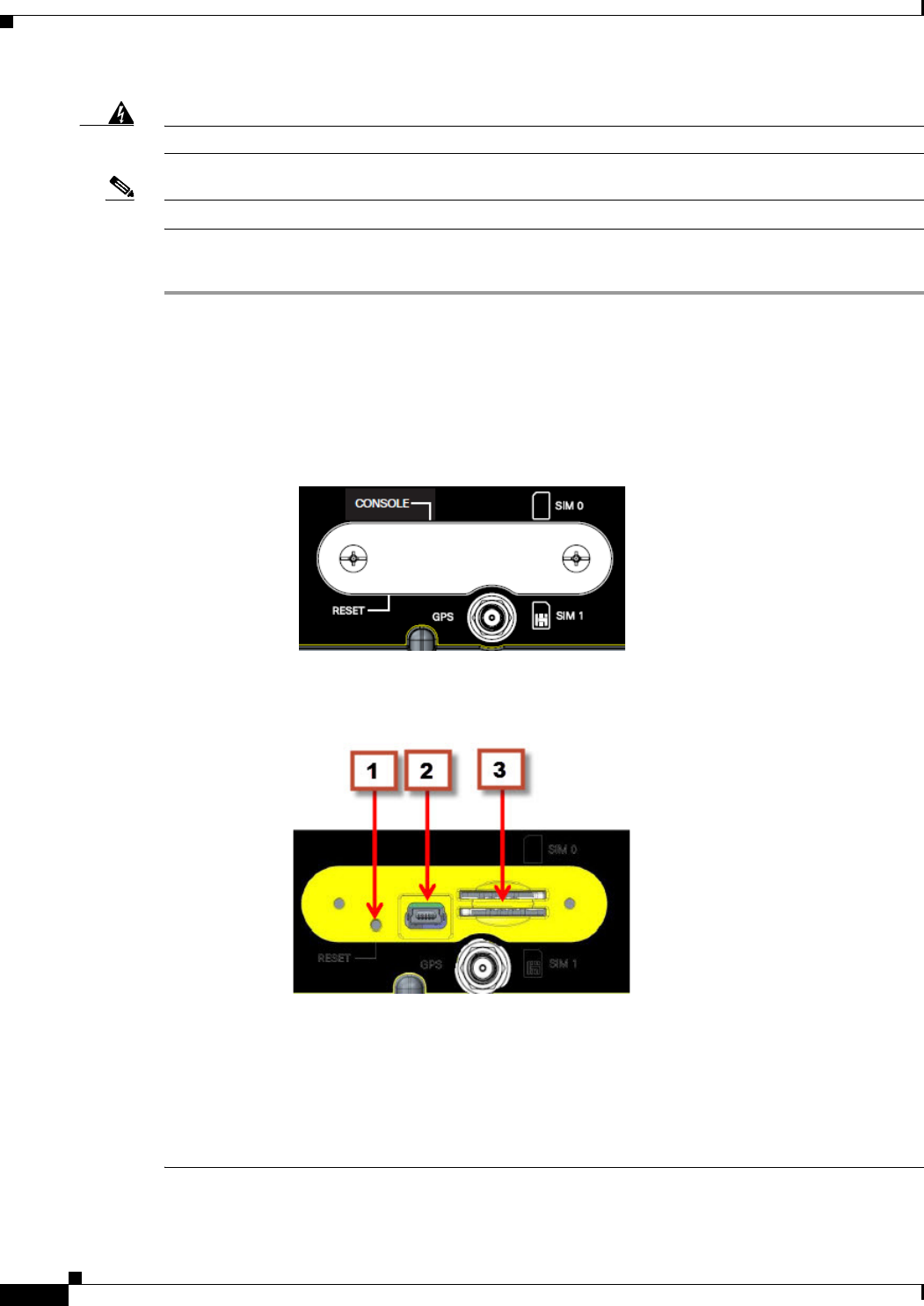
To access the SIM card in the Cisco IR829, follow these steps:
Step 1 Place the router on its bottom and ensure that any installed antennas are carefully oriented.
Step 2 Remove the SIM access panel using two Phillips head screws. (See Figure 2-1.)
Step 3 Locate the SIM card you wish to install/replace. Details are shown in Figure 2-2.
Step 4 Remove the SIM card (if present) and install the new card(s).
Figure 2-1 Accessing the SIM Cards
Figure 2-2 Sim Card Detail
1. Reset Switch
2. Mini USB Port
3. Dual Sim Slots
Step 5 Replace the panel and the screws.

2-5
Cisco IR829 Integrated Services Router Hardware Installation Guide
Chapter 2 Installing the Router
Installing the Router
Installing Antennas
Note Before you install the Cisco IR829 Integrated Services Router on a table, wall, or DIN rail, install the
antennas on the front panel. It is difficult to install the antennas after the router is installed.
There are four TNC connectors on the front side of the chassis. There are two TNC and one SMA
connectors on the back side of the chassis. Two TNC connectors are used to connect to the 4G modem.
The four TNC connectors at the back will be connected to the two 4G modems. The front two TNC
connectors will be used for WiFi.
Orient the antennas. For optimum wireless performance, the antennas should be perpendicular with
respect to the floor.
If the router is being mounted on a desk, orient the antennas straight up.
To attach the radio antennas to your wireless router, follow these steps:
Step 1 Manually screw the antenna tight to the TNC connectors on the back of the router.
Step 2 Orient the antennas. For optimum wireless performance, antennas should be generally perpendicular to
each other.
Mounting on a Wall, Table, or Other Flat Surface
The Cisco IR829 has mounting holes on the bottom of the chassis for mounting the unit on a wall or
other vertical surface. The attachment hardware is provided.
Tip When choosing a location for wall-mounting the router, consider cable limitations and wall structure.
Warning
Read the wall-mounting instructions carefully before beginning installation. Failure to use the
correct hardware or to follow the correct procedures could result in a hazardous situation to people
and damage to the system.
Statement 378
To mount the router on a wall, follow these steps:
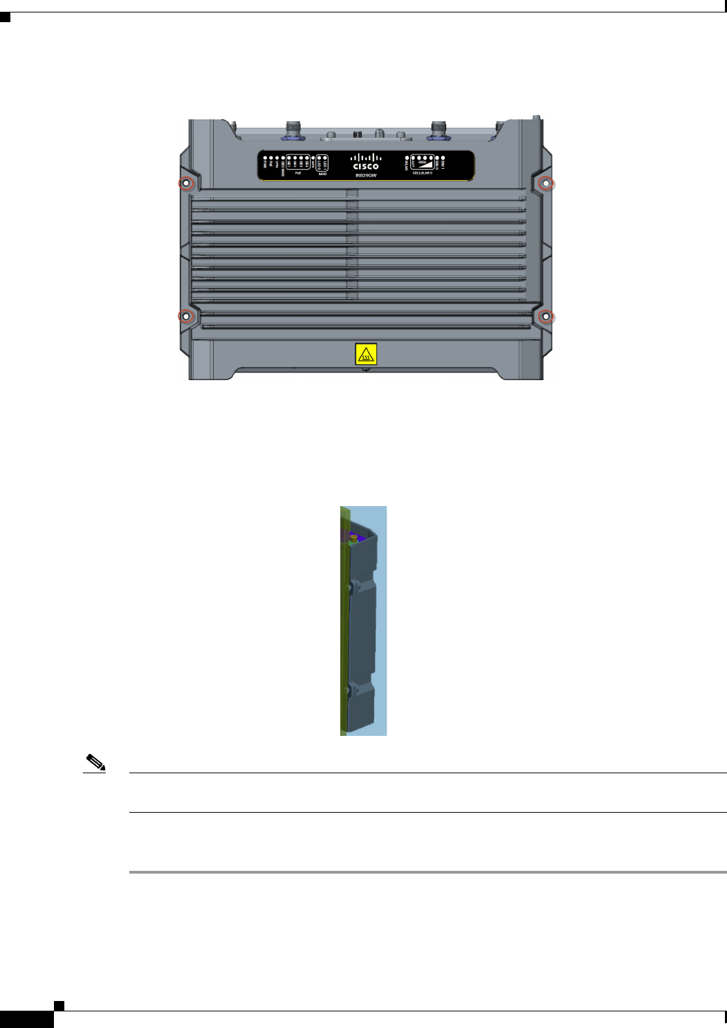
Step 1 Locate the mounting holes on the router. There are 4 holes are shown circled in red in Figure 2-3.
2-6
Cisco IR829 Integrated Services Router Hardware Installation Guide
Chapter 2 Installing the Router
Installing the Router
Figure 2-3 Cisco IR829 Mounting Holes
Step 2 Install the router to a wall stud using two number-10 wood screws, round- or pan-head, with number-10
washers or two number-10 washer-head screws. The screws must be long enough to penetrate at least 1.0
inch (25.4 mm) into the supporting wood or metal wall stud. (See Figure 2-4.)
Figure 2-4 Mounted to wall
Note For hollow-wall mounting, each bracket requires two wall anchors with washers. Wall anchors and
washers must be size number 10.
Step 3 Route the cables so that they do not put a strain on the connectors or mounting hardware. Cables should
be routed down relative to the router to prevent water from traveling on the cables.
2-7
Cisco IR829 Integrated Services Router Hardware Installation Guide
Chapter 2 Installing the Router
Installing the Router
Installing the Router Ground Connection
The router must be connected to a reliable earth ground. Install the ground wire in accordance with local
electrical safety standards.
• For NEC-compliant grounding, use size 14 AWG (2 mm2) or larger copper wire and a ring terminal
with an inner diameter of 1/4 in. (5 to 7 mm).
• For EN/IEC 60950-compliant grounding, use size 18 AWG (1 mm2) or larger copper wire.
Warning
This equipment must be grounded. Never defeat the ground conductor or operate the equipment in the
absence of a suitably installed ground conductor. Contact the appropriate electrical inspection
authority or an electrician if you are uncertain that suitable grounding is available.
Statement 1024
Warning
This equipment needs to be grounded. Use a green and yellow 12 to 14 AWG ground wire to connect
the host to earth ground during normal use.
Statement 242
To install the ground connection, follow these steps:
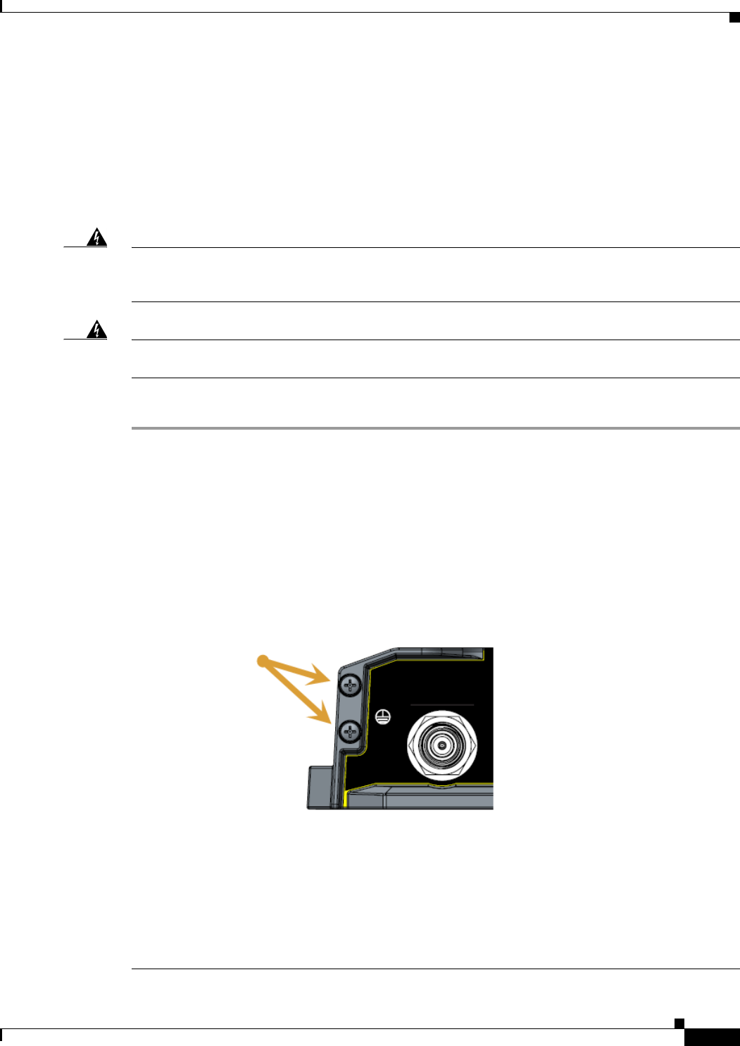
Step 1 Locate the grounding lug attached to the back of the Cisco IR829. It will be attached underneath two
screws. Remove the screws holding it to the router and set it aside for reuse.
Step 2 Strip one end of the ground wire to the length required for the terminal.
Step 3 Crimp the ground wire to the grounding lug using the wire crimper.
Step 4 Attach the grounding lug to the chassis using the screws set aside in step 1. Tighten the screw to a torque
of 8 to 10 inch-pound (0.9 to 1.1 newton meter). (See Figure 2-5.)
Figure 2-5 Chassis Ground Connection Points
Step 5 Connect the other end of the ground wire to a known reliable earth ground point at your site.
Step 6 If you are using this router in a vehicle, attach the ring terminal to the chassis using one of the screws
provided and the green or green and yellow striped wire. Connect the other end of the wire to the vehicle
ground.
After you install and properly ground the router, you can connect the power wiring, the LAN cables, and
the cables for administrative access as required for your installation.

2-8
Cisco IR829 Integrated Services Router Hardware Installation Guide
Chapter 2 Installing the Router
Installing the Router

CHAPTER
3-1
Cisco IR829 Integrated Services Router Hardware Installation Guide
3
Connecting the Router
This chapter describes how to connect Cisco IR829 Integrated Services Router (ISRs) to Ethernet
devices and a network. The chapter contains the following sections:
• Preparing to Connect the Router, page 3-1
• Connecting a PC, Server, or Workstation, page 3-2
• Connecting a Terminal or PC to the Console Port, page 3-3
• Connecting to DC Power, page 3-3
• Verifying Connections, page 3-6
Note For compliance and safety information, see the Regulatory Compliance and Safety Information
Roadmap that ships with the router and Regulatory Compliance and Safety Information for Cisco 800
Series and SOHO Series Routers.
Preparing to Connect the Router
Before you connect the router to the devices, install the router according to the instructions in Chapter 2,
“Installing the Router”.
Preventing Damage to the Router
To prevent damage to your router, follow these guidelines when connecting devices to your router:
• Turn off power to the devices and to the router until all connections are completed.
Caution Do not turn on the devices until after you have completed all connections to the router.
• If you must supply your own cable, see the “Technical Specifications” section on page 6-1 for
cabling specifications. If this appendix does not provide specifications for a particular cable, we
strongly recommend ordering the cable from Cisco.

3-2
Cisco IR829 Integrated Services Router Hardware Installation Guide
Chapter 3 Connecting the Router
Preparing to Connect the Router
Connecting a PC, Server, or Workstation
To connect a PC (or other Ethernet devices) to an Ethernet switch port, follow these steps:
Step 1 Connect one end of the Ethernet cable to an Ethernet switch port on the router. In this example a PC is
being connected to GE LAN Port 2. See Figure 3-1.
Figure 3-1 Connecting a Server, PC, or Workstation
Step 2 Connect the other end of the cable to the RJ-45 port on the network interface card (NIC) that is installed
in the PC, server, or workstation.
1Ethernet cable 3RJ-45 port on the PC, Server, or Workstation
2Ethernet switch port on the router
3-3
Cisco IR829 Integrated Services Router Hardware Installation Guide
Chapter 3 Connecting the Router
Connecting a Terminal or PC to the Console Port
Step 3 (Optional) Connect additional servers, PCs, or workstations to the other Ethernet switch ports.
Connecting a Terminal or PC to the Console Port
Connect a terminal or PC to the Console port either to configure the software by using the CLI or to
troubleshoot problems with the router.
To connect a terminal or PC to the console port on the router and access the CLI, follow these steps:
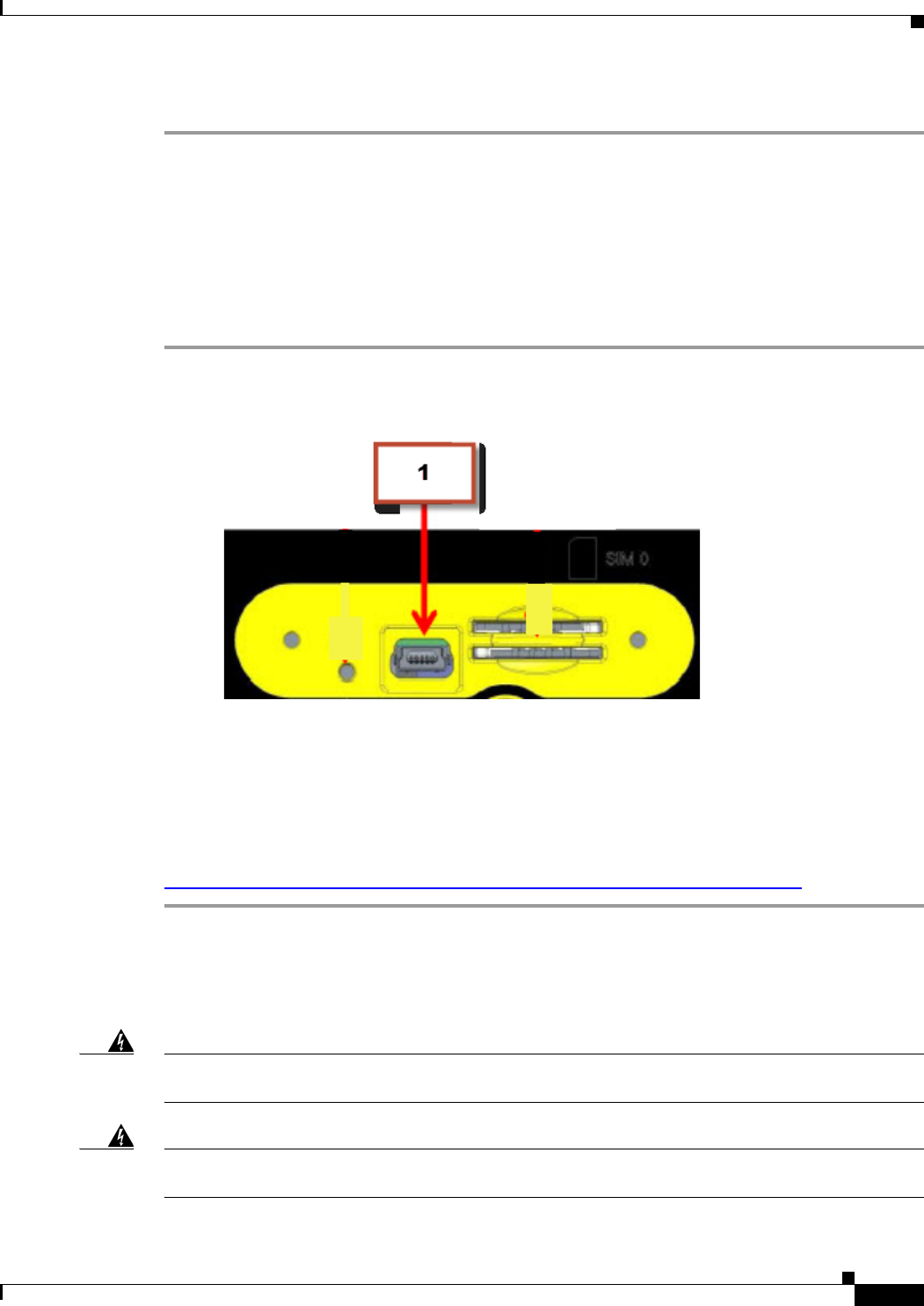
Step 1 Connect the mini-USB side of a cable to the USB Console port on the router. Figure 3-2 shows the
mini-USB location (1) for the Console port on the router.
Figure 3-2 Connecting a Terminal or PC to the Console Port
Step 2 Connect the opposite end of the mini-USB cable to the USB port on your laptop or PC.
Step 3 To communicate with the router, wait for your laptop or PC to discover the new device.
Step 4 If your laptop or PC warns you that you do not have the proper drivers to communicate with the router,
you can obtain them from your computers manufacturer, or go here:
https://www.silabs.com/products/mcu/Pages/USBtoUARTBridgeVCPDrivers.aspx
Connecting to DC Power
Warning
This product relies on the building’s installation for short-circuit (overcurrent) protection. Ensure that
the protective device is rated not greater than 36 VDC, 5A
Statement 1005
Warning
This product requires short-circuit (overcurrent) protection, to be provided as part of the building
installation. Install only in accordance with national and local wiring regulations.
Statement 1045
3-4
Cisco IR829 Integrated Services Router Hardware Installation Guide
Chapter 3 Connecting the Router
Connecting to DC Power
Plugs and Pin-Outs
The IR829 ships with a DC power accessory kit that contains a 4-pin locking connector and pins to use
for the power connections. Four contacts are supplied, but only three are used. One is a spare.
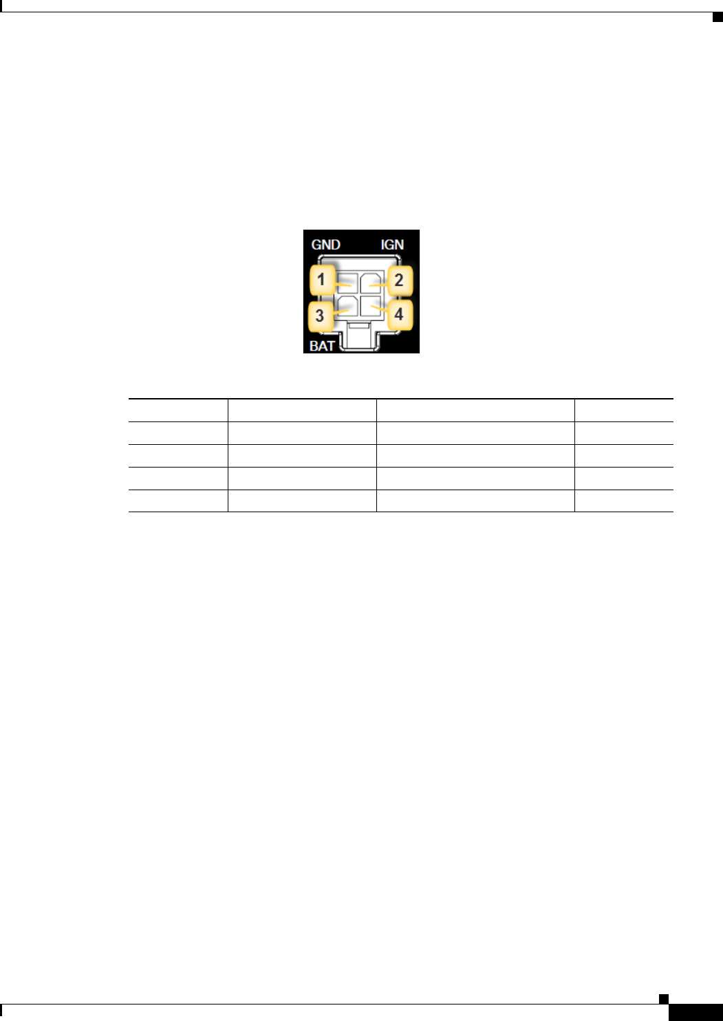
The power entry receptacle is on the IR829. The pin-outs are shown in Figure 3.
Figure 3 Power Connector Pin-outs
Figure 4 Power connector Descriptions
Constructing a Power cable
Special care should be taken when making the connections for DC power. It is easy to make a mistake
when crimping connections, and there is a very good tutorial available at Molex:
http://www.molex.com/tnotes/crimp.html
The specifications for the wiring are as follows:
• 16 AWG (1.02-to-1.29mm)
• UL1015 Rated
• Wires will be wound at 1 twist per inch
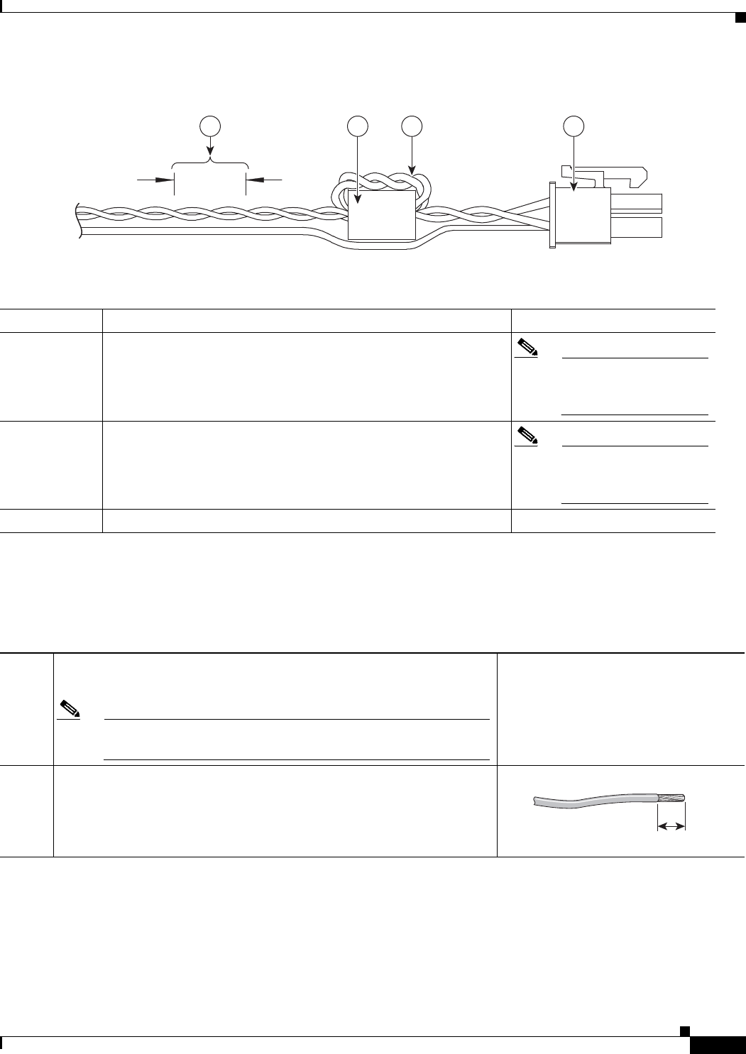
The example in Figure 3-5 shows a cable constructed with a ferrite for a different certification. You can
build your cable without the ferrite eliminating items 2 and 3 in the diagram.
Pin Number Name Description Color
1 DC In - DC Power Return (GND-) Black
2 Ignition Ignition Input (IGN) Blue
3 DC In + DC Power In (BAT+) Red
4N/A N/A N/A
3-5
Cisco IR829 Integrated Services Router Hardware Installation Guide
Chapter 3 Connecting the Router
Connecting to DC Power
Figure 3-5 Power cable
Details listed in the power cable example are:
Wiring the DC Power
To connect the DC power on your Cisco IR829, follow these steps:
4 3 2 1
349790
14-pin locking connector
22 loops of DC power and power return wires only. Other wires that
may be used should run outside the Ferrite. Note Ferrite bead and the
loops of wire are not
needed at this time.
3Ferrite Bead
Note Ferrite bead and the
loops of wire are not
needed at this time.
4Wires wound at 1 twist per inch
Step 1 Identify the DC power source and measure 4 strands of copper wire 16
AWG (1.29mm) long enough to connect to the DC power source.
Note The maximum length of the cable before twisting is 15 feet (4.6
meters).
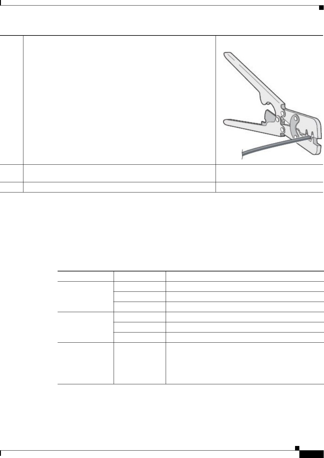
Step 2 Using an 16-gauge wire-stripping tool, strip each of the wires coming
from each DC-input power source to 0.25 inch (6.3 mm) ± 0.02 inch (0.5
mm). Do not strip more than 0.27 inch (6.8 mm) of insulation from the
wire. Stripping more than the recommended amount of wire can leave
exposed wire from the power connector after installation.
333084
3-6
Cisco IR829 Integrated Services Router Hardware Installation Guide
Chapter 3 Connecting the Router
Verifying Connections
Verifying Connections
To verify that all devices are properly connected to the router, first turn on all the connected devices,
then check the LEDs. To verify router operation, refer to Table 3-1.
For full LED description, see Chapter 1, “LEDs”
Step 3 Using the pins included in the kit, crimp each pin onto a wire.
Step 4 Insert the pins into the power connector, referring to previous figures for
guidance.
Step 5 Plug the connector into the power entry receptacle.
Ta b l e 3-1 Verifying the Router Operation
Power and Link LEDs to Check Normal Patterns
PWR Green steady On Normal operation
Green (blinking) Boot up phase or in ROM Monitor mode
Yel low System shutdown due to under or over voltage conditions
GE0 WAN Steady On Link is up
Flashing Transmitting and Receiving data
Off No network activity.
Ethernet LAN
Switch Ports
Single LED per
port
Off — No link
Green Steady on — Link is up
Green Blink — Transmitting and Receiving data
Yellow — POE Fault, implies no link

3-7
Cisco IR829 Integrated Services Router Hardware Installation Guide
Chapter 3 Connecting the Router
Verifying Connections
Sim cards SIM0/SIM1 Off — No USIM
Green — USIM installed and active
Cellular Modems CELLULAR0/
CELLULAR1
Off — Module not powered on
On — Module is powered on and connected but not
transmitting or receiving
Slow Blink — Module is powered on and searching for
connection
Fast Blink — Module is transmitting or receiving.
Table 3-1 Verifying the Router Operation (continued)
Power and Link LEDs to Check Normal Patterns

CHAPTER
4-1
Cisco IR829 Integrated Services Router Hardware Installation Guide
4
Initial Configuration
This chapter provides instructions for initial configuration of the Cisco IR829 Integrated Services
Routers (ISRs). To create the initial configuration, the setup command facility prompts you for basic
information about your router and network.
This chapter contains the following sections:
• Setup Command Facility, page 4-1
• Verifying the Initial Configuration, page 4-4
• Where To Go From Here, page 4-4
Setup Command Facility
The setup command facility guides you through the configuration process by prompting you for the
specific information that is needed to configure your system. Use the setup command facility to
configure a hostname for the router, to set passwords, and to configure an interface for communication
with the management network.
To use the setup command facility, you must set up a console connection with the router and enter the
privileged EXEC mode.
To configure the initial router settings by using the setup command facility, follow these steps:
Step 1 Set up a console connection to your router, and enter privileged EXEC mode.
Step 2 In privileged EXEC mode, at the prompt, enter setup.
yourname# setup
The following message is displayed:
--- System Configuration Dialog ---
Would you like to enter the initial configuration dialog? [yes/no]:
You are now in the setup command facility.
The prompts in the setup command facility vary, depending on your router model, on the installed
interface modules, and on the software image. The following steps and the user entries (in bold) are
shown as examples only.

4-2
Cisco IR829 Integrated Services Router
Chapter 4 Initial Configuration
Setup Command Facility
Note If you make a mistake while using the setup command facility, you can exit and run the setup
command facility again. Press Ctrl-C and enter the setup command at the privileged EXEC
mode prompt (Router#). To proceed using the setup command facility, enter yes.
Would you like to enter the initial configuration dialog? yes
Step 3 When the following messages appear, enter yes to enter basic management setup.
At any point you may enter a question mark '?' for help.
Use ctrl-c to abort configuration dialog at any prompt.
Default settings are in square brackets '[]'.
Basic management setup configures only enough connectivity
for management of the system, extended setup will ask you
to configure each interface on the system
Would you like to enter basic management setup? [yes/no]: yes
Step 4 Enter a hostname for the router (this example uses Router).
Configuring global parameters:
Enter host name [Router]: Router
Step 5 Enter an enable secret password. This password is encrypted (more secure) and cannot be seen when
viewing the configuration.
The enable secret is a password used to protect access to
privileged EXEC and configuration modes. This password, after
entered, becomes encrypted in the configuration.
Enter enable secret: xxxxxx
Step 6 Enter an enable password that is different from the enable secret password. This password is not
encrypted (less secure) and can be seen when viewing the configuration.
The enable password is used when you do not specify an
enable secret password, with some older software versions, and
some boot images.
Enter enable password: xxxxxx
Step 7 Enter the virtual terminal password, which prevents unauthenticated access to the router through ports
other than the console port.
The virtual terminal password is used to protect
access to the router over a network interface.
Enter virtual terminal password: xxxxxx
Step 8 Respond to the following prompts as appropriate for your network:
Configure SNMP Network Management? [yes]:
Community string [public]:
A summary of the available interfaces is displayed. The following is an example summary and may not
reflect your configuration:
Current interface summary
Any interface listed with OK? value "NO" does not have a valid configuration
Interface IP-Address OK? Method Status Protocol
GigabitEthernet0 20.1.0.165 YES DHCP up up
GigabitEthernet1 unassigned NO unset up up

4-3
Cisco IR829 Integrated Services Router Hardware Installation Guide
Chapter 4 Initial Configuration
Setup Command Facility
Async0 unassigned YES unset up down
Async1 unassigned YES unset up down
GigabitEthernet2 unassigned NO unset up up
Cellular0 unassigned NO unset down down
Cellular1 unassigned NO unset down down
Step 9 Choose one of the available interfaces for connecting the router to the management network.
Enter interface name used to connect to the
management network from the above interface summary: GigabitEthernet0
Step 10 Respond to the following prompts as appropriate for your network:
Configuring interface GigabitEthernet0:
Configure IP on this interface? [yes]: yes
Use the 100 Base-TX (RJ-45) connector? [yes]: yes
Operate in full-duplex mode? [no]: yes
Configure IP on this interface? [yes]: yes
IP address for this interface: 172.1.2.3
Subnet mask for this interface [255.255.0.0] : 255.255.0.0
Class B network is 172.1.0.0, 26 subnet bits; mask is /16
The configuration is displayed:
The following configuration command script was created:
hostname Router
enable secret 5 $1$D5P6$PYx41/lQIASK.HcSbfO5q1
enable password xxxxxx
line vty 0 4
password xxxxxx
snmp-server community public
!
no ip routing
!
interface GigabitEthernet0
no shutdown
speed 100
duplex auto
ip address 172.16.2.3 255.255.0.0
!
Step 11 Respond to the following prompts. Enter 2 to save the initial configuration.
[0] Go to the IOS command prompt without saving this config.
[1] Return back to the setup without saving this config.
[2] Save this configuration to nvram and exit.
Enter your selection [2]: 2
Building configuration...
Use the enabled mode 'configure' command to modify this configuration.
Press RETURN to get started! RETURN
The user prompt is displayed.
Router>
Step 12 Verify the initial configuration. See the “Verifying the Initial Configuration” section on page 4-4 for
verification procedures.

4-4
Cisco IR829 Integrated Services Router
Chapter 4 Initial Configuration
Verifying the Initial Configuration
After the initial configuration file is created, you can use the Cisco IOS CLI to perform additional
configuration.
Verifying the Initial Configuration
To verify that the new interfaces are operating correctly, perform the following tests:
• To verify that the interfaces and line protocol are in the correct state—up or down—enter the show
interfaces command.
• To display a summary status of the interfaces configured for IP, enter the show ip interface brief
command.
• To verify that you configured the correct hostname and password, enter the show configuration
command.
After you complete and verify the initial configuration, you can configure your Cisco router for specific
functions.
Where To Go From Here
There are a wide variety of configuration options available on the Cisco IR829. The rest of this chapter
will discuss different pieces of documentation to refer to, as well as point out the differences between
this device and the rest of the 800 series routers.
800 Series Documentation
The home for all of the 800 series router documentation is here:
http://www.cisco.com/c/en/us/support/routers/800-series-routers/tsd-products-support-series-home.ht
ml
Most of the Cisco IR829 configuration tasks are available in the Cisco 800 Series Integrated Services
Routers Software Configuration Guide:
http://www.cisco.com/c/en/us/td/docs/routers/access/800/software/configuration/guide/SCG800Guide.
htm
Some common tasks between the Cisco 800 series and the Cisco IR829 are listed here:
Configuring Wireless Devices
http://www.cisco.com/c/en/us/td/docs/routers/access/800/software/configuration/guide/SCG800Guide/
SCG800_Guide_BookMap_chapter_01001.html
Cisco 4G LTE Software Installation Guide
http://www.cisco.com/c/en/us/td/docs/routers/access/interfaces/software/feature/guide/EHWIC-4G-LT
ESW.html

4-5
Cisco IR829 Integrated Services Router Hardware Installation Guide
Chapter 4 Initial Configuration
Cisco IR829 Differences
Cisco IR829 Differences
This section will discuss some of the ways that the Cisco IR829 differs from the rest of the 800 series.
LEDs
The Cisco IR829 has LEDs that are discussed in previous chapters in this guide. There is also a command
that will show you the status of the LEDs if you are not near the device. Use the show platform led
command with options to view the different output.
IR800#show platform led
LED STATUS:
==================================================
GE PORTS : GE0 GE1 GE2 GE3 GE4
LINK LED : GREEN GREEN GREEN GREEN OFF
==================================================
PoE LED : GREEN
Cellular PORTS: Cellular0
RSSI LED 1 : Green
RSSI LED 2 : Green
RSSI LED 3 : Off
GPS LED : Slow Blinking
SIM0 LED : Green
SIM1 LED : Off
==================================================
VPN LED : OFF
System LED: amber, blinking
IR800#show platform led summary
Ports LINK/ENABLE
-------+---------------
GE0 GREEN
GE1 GREEN
GE2 GREEN
GE3 GREEN
GE4 OFF
-------+---------------
PoE LED : GREEN
RSSI 1 RSSI 2 RSSI 3 GPS
-----+------------+------------+------------+-------------
Ce0 Green Green Off Slow Blink
-----+------------+------------+------------+-------------
Cellular SIM0 SIM1
--------+-------+-------
Ce0 Green Off
--------+-------+-------
VPN LED : OFF
System LED: amber, blinking

4-6
Cisco IR829 Integrated Services Router
Chapter 4 Initial Configuration
Cisco IR829 Differences
IR800#show platform led system
System LED: amber, blinking
Summary of the LED status providers:
Client Type Status
------------------------------ -------- --------
GigabitEthernet5 critical OK
Note There may be a lag time between the LED indication on the router and what the show led commands
return.
Software Bundle Installation
The Cisco IR829 ships with the latest software available with the configuration that was ordered. There
should be no reason to have to upgrade unless a failure occurs or you have been instructed to reload all
software. Should the need arise, the following steps will assist in performing a bundle installation.
Overview:
1. Download the bundle to flash memory from a TFTP server.
2. Install the bundle from the Command Line Interface
3. Save the configuration and reload the router to use the new image.
4. Download the 4G firmware upgrade.
Example:
Step 1 Copy the bundle from a TFTP server to your router.
IR800#copy tftp flash
Address or name of remote host [223.255.254.254]? your ip address here
Source filename [path to file/ir800-universalk9-bundle.SSA.156-0.3.T]?
Destination filename [ir800-universalk9-bundle.SSA.156-0.3.T]?
Accessing tftp://223.255.254.254/tachen/ir800-universalk9-bundle.SSA.156-0.3.T...
Loading tachen/ir800-universalk9-bundle.SSA.156-0.3.T from 223.255.254.254 (via Vlan1): !
*Jun 25 18:28:45.685: %ARP-4-NULL_SRC_MAC: NULL MAC address from 99.99.0.1 on
wl0!!!!!!!!!!!!!!!!!!!!!!!!!!!!!!!!!!!!!!!!!!!!!!!!!!!!!!!!!!!!!!!!!!!!!!!!!!!!!!!!!!!!!!!
!!!!!!!!!!!!!!!!!!!!!!!!!!!!!!!!!!!!!!!!!!!!!!!!!!!!!!!!!!!!!!!!!!!!!!!!!!!!!!!!!!!!!!!!!!
!!!!!!!!!!!!!!!!!!!!!!!!!!!!!!!!!!!!!!!!!!!!!!!!!!!!!!!!!!!!!!!!!!!!!!!!!!!!!!!!!!!!!!!!!!
!!!!!!!!!!!!!!!!!!!!!!!!!!!!!!!!!!!!!!!!!!!!!!!!!!!!!!!!!!!!!!!!!!!!!!!!!!!!!!!!!!!!!!!!!!
!!!!!!!!!!!!!!!!!!!!!!!!!!!!!!!!!!!!!!!!!!!!!!!!!!!!!!!!!!!!!!!!!!!!!!!!!!!!!!!!!!!!!!!!!!
!!!!!!!!!!!!!!!!!!!!!!!!!!!!!!!!!!!!!!!!!!!!!!!!!!!!!!!!!!!!!!!!!!!!!!!!!!!!!!!!!!!!!!!!!!
!!!!!!!!!!!!!!!!!!!!!!!
[OK - 143536651 bytes]
143536651 bytes copied in 774.390 secs (185354 bytes/sec)
Step 2 The bundle download is complete, and now needs to be installed. Perform the bundle install flash:
< bundle iOS image name> command.
IR800#bundle install flash:ir800-universalk9-bundle.SSA.156-0.3.T
Installing bundle image:
/ir800-universalk9-bundle.SSA.156-0.3.T...................................................
........................................
updating Hypervisor image...
Sending file modes: C0444 23753557 ir800-hv.srp.SPA.0.28
SRP md5 verification passed!

4-7
Cisco IR829 Integrated Services Router Hardware Installation Guide
Chapter 4 Initial Configuration
Cisco IR829 Differences
updating IOS image...
Sending file modes: C0644 61505652 ir800-universalk9-mz.SSA.156-0.3.T
IOS md5 verification passed!
Done!
IR800#
*Jun 25 18:51:16.975: %SYS-5-CONFIG_I: Configured from console by bundle install command
*Jun 25 18:51:16.975: %IR800_INSTALL-6-SUCCESS_BUNDLE_INSTALL: Successfully installed
bundle image.
Step 3 Save the configuration and reload the router.
IR800#reload
Do you want to reload the internal AP ? [yes/no]: yes
System configuration has been modified. Save? [yes/no]: yes
Building configuration...
[OK]
Proceed with reload? [confirm]press return
*Jun 25 19:03:13.685: %SYS-5-RELOAD: Reload requested by console. Reload Reason: Reload
Command.
Step 4 Download the 4G firmware or AP image. Instructions for uploading firmware are located here:
http://www.cisco.com/c/en/us/td/docs/routers/access/interfaces/software/feature/guide/EHWIC-4G-LT
ESW.html
Search for “Upgrading the Modem Firmware”.

4-8
Cisco IR829 Integrated Services Router
Chapter 4 Initial Configuration
Cisco IR829 Differences

CHAPTER
5-1
Cisco IR829 Integrated Services Router Hardware Installation Guide
5
Guest Operating System (Guest OS) Installation
and Configuration
This chapter details Guest Operating System (Guest OS) installation for the Cisco IR829.
This chapter contains the following sections:
• Guest Operating System Overview, page 5-1
• Prerequisites, page 5-2
• Guidelines and Limitations, page 5-2
• Installation and Upgrade, page 5-2
• Configuring Cisco IOS, page 5-3
• Configuring Guest OS, page 5-6
• Configuring NAT, page 5-8
• Troubleshooting, page 5-9
• Related Documentation, page 5-9
Guest Operating System Overview
The IR829 supports a Hypervisor architecture to support multiple user-specified operating systems
within independent Virtual Machines (VMs). Specific functions include Serial Relay and Network
Address Translation (NAT).
Cisco IOS interacts closely with the platform and underlying Hypervisor. Cisco Guest OS allows you to
run the Linux operating system (if within the memory, disk, and CPU budget) next to Cisco IOS on the
Hypervisor. Cisco Guest OS does not require signing, allowing maximum deployment latitude; however
you must ensure the integrity and proper behavior for any Guest OS that you install.
When you install the IR829 software bundle (image) on the router, the image automatically installs the
supported Guest OS (Cisco IOS and Linux OS) instance(s). You can use the Linux Guest OS running on
a VM on the IR829 to run utility applications.
The following example shows connectivity of Guest OS and Cisco IOS. A virtual interface (see
Configuring Guest OS Interface on Cisco IOS) managed by Cisco IOS provides network connectivity to
Guest OS. Cisco IOS forwards traffic from Guest OS through regular IP forwarding mechanisms.
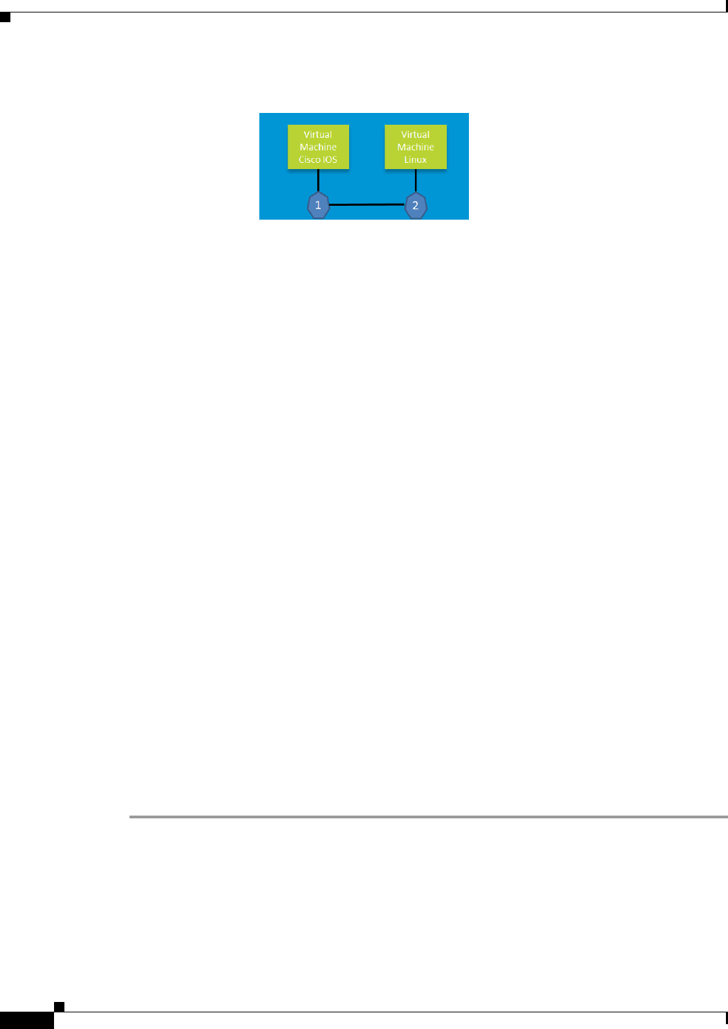
5-2
Cisco IR829 Integrated Services Router
Chapter 5 Guest Operating System (Guest OS) Installation and Configuration
Prerequisites
Figure 5-1 Connectivity Between Cisco IOS and Guest OS
In this example, number 1 is the interface being used on the router and number 2 is the interface on the
Linux OS. For the Cisco IR829, 1 is Gigabit Ethernet 5 and 2 is Eth 0.
Prerequisites
• Router must be running Cisco IOS.
Guidelines and Limitations
• The bundled Guest OS is based on Linux kernel version 3.8.11.
• You must configure Cisco IOS to provide Guest OS Connectivity.
Default Settings
The bundled Linux Guest OS:
• uses DHCP to acquire the IP address.
• does not have a default root password.
Installation and Upgrade
By default, IR829s ship with a software bundle that includes the latest versions of all of the required
images such as Cisco IOS, Guest OS, and Hypervisor.
Use the following procedure to upgrade your router to the latest software bundle. It can take several
minutes for the router to upgrade and install all of the images (Hypervisor, Cisco IOS, and Guest OS).
DETAILED STEPS
Step 1 Copy the bundle image to the IR829 IOS flash partition using scp or sftp.
Example bundle name: ir800-universalk9-bundle.SPA.<VERSION>
Step 2 Enter the following commands at the IR829 prompt:

5-3
Cisco IR829 Integrated Services Router Hardware Installation Guide
Chapter 5 Guest Operating System (Guest OS) Installation and Configuration
Configuring Cisco IOS
Configuring Cisco IOS
This section describes how to configure the Cisco IOS VM to provide network connectivity to the Guest
OS VM.
Guest OS connects to the network through a virtual Network Interface Card (VNIC) provided by the
Hypervisor. Network attributes on the interface are statically configured or configured for DHCP to
dynamically obtain IP addresses. Guest OS network connectivity is only through Cisco IOS, using the
virtual network interface provided by the Hypervisor. Network attributes such as IP address, can be
configured statistically or dynamically, and are obtained from Cisco IOS using DHCP requests. The
bundled Linux Guest OS is configured to use DHCP.
This section outlines the task to configure a Cisco IOS DHCP pool to provision the Linux Guest OS with
an IP address, and an external Ethernet interface in Cisco IOS to allow the Guest OS network
connectivity.
This section includes the following topics:
• Configuring the IR829 Ethernet Interface, page 5-3
• Configuring Guest OS Interface on Cisco IOS, page 5-5
• Enabling Guest OS Console, page 5-6
Configuring the IR829 Ethernet Interface
You must enable one of the external Ethernet interfaces on the IR829 to provide network connectivity.
For details on interface configuration refer to the Cisco 800 Series Integrated Services Routers Software
Configuration Guide:
http://www.cisco.com/c/en/us/td/docs/routers/access/800/software/configuration/guide/SCG800Guide.
html
IPv6 Gigabit Ethernet
On Guest OS, IPv6 is enabled by default. The following example configuration uses IPv6 on Guest OS,
where Guest OS is automatically assigned an IPv6 address by enabling prefix delegation on the Cisco
IOS interface GigabitEthernet 5.
The following example configures G 0 for external connectivity:
interface GigabitEthernet 0
no switchport
ipv6 address autoconfig default
ipv6 enable
Command Purpose
bundle install flash: <bundle name>.CG Installs the specified bundle.
copy running config-config startup-config Saves the current running configuration.
reload Reloads the router.

5-4
Cisco IR829 Integrated Services Router
Chapter 5 Guest Operating System (Guest OS) Installation and Configuration
Configuring Cisco IOS
ipv6 dhcp client pd prefix-from-provider
end
The following example configures G5 to allow the Guest OS network connectivity:
interface GigabitEthernet 5
duplex auto
speed auto
ipv6 address prefix-from-provider ::2:0:0:0:1/64
ipv6 enable
end
Enabling IPv4 Gigabit Ethernet
To enable an external Gigabit Ethernet IPv4 interface on the IR829 to provide network connectivity, enter the following
commands:
Configuring DHCP Pool
To configure a local DHCP pool, enter the following commands, one per line:
Note The subnet used for the local DHCP pool must be reachable externally. If you cannot allocate the whole
subnet to Guest OS, use a NAT-based configuration. See Configuring NAT.
Command Purpose
config terminal Enters global configuration mode.
interface gig 0 Configures an IPv4 address on Gigabit Ethernet
interface 0, and enters interface configuration
mode.
ip address 9.1.1.5 255.255.255.0 Sets the IP address and subnet mask for Gigabit
Ethernet interface 0.
no shutdown Enables the Gigabit Ethernet interface.
Command Purpose
config terminal Enters global configuration mode.
ip dhcp pool gospool Names the local DHCP pool.
network 9.1.2.0 255.255.255.0 Sets the network address.
default-router 9.1.2.1 Sets the router address.
domain-name utility.com Sets the subnet address.
dns-server 9.1.1.1 Sets the DNS server address.
lease 5 Sets the duration of the IP address lease to five
days.

5-5
Cisco IR829 Integrated Services Router Hardware Installation Guide
Chapter 5 Guest Operating System (Guest OS) Installation and Configuration
Configuring Cisco IOS
Configuring Guest OS Interface on Cisco IOS
The Guest OS Ethernet port (eth0) connects to GigabitEthernet 5 on Cisco IOS. To configure the
GigabitEthernet 5 interface with the default gateway address of the DHCP pool, enter the following
commands:
Note IPv6 must always be enabled on GigabitEthernet 5.
Note There exists a condition where the IR829 could display slow performance if the guest OS is consuming
too many CPU resources.
By default, Guest OS gets 50% of one of the cores of the CPU. The following command allows you to
change the percentage of CPU allocation to VDS out of 100. The rest will go to Guest OS. In the situation
where you don't use the Guest OS, the CPU can be allocated 90% to VDS.
For Example:
IR800>en
IR800#config t
Enter configuration commands, one per line. End with CNTL/Z.
IR800(config)#iox hypervisor ?
sched-policy percentage of CPU ticks to VDS
IR800(config)#iox hypervisor sched-policy ?
10 VDS 10% Guest OS 90%
20 VDS 20% Guest OS 80%
30 VDS 30% Guest OS 70%
40 VDS 40% Guest OS 60%
50 VDS 50% Guest OS 50%
60 VDS 60% Guest OS 40%
70 VDS 70% Guest OS 30%
80 VDS 80% Guest OS 20%
90 VDS 90% Guest OS 10%
IR800(config)#iox hypervisor sched-policy 90
Command Purpose
interface GigabitEthernet 5 Set the internal virtual interface that
connects to the Linux Guest OS.
ipv6 enable Enables IPv6.
ipv6 address 2001:DB8:FFFF:0000:0000:0000:0001 Sets the IPv6 address.
ipv4 enable Enables IPv4.
ipv4 address 9.1.2.1 255.255.255.0 Sets the IPv4 address.
no shutdown

5-6
Cisco IR829 Integrated Services Router
Chapter 5 Guest Operating System (Guest OS) Installation and Configuration
Configuring Guest OS
Enabling Guest OS Console
For heightened security, Guest OS console is disabled by default. To enable Guest OS console, enter the
following commands:
Configuring Guest OS
This section describes how to set the root password for Guest OS and enable SSH access. By default,
SSH is disabled in Guest OS, this section describes the steps to reverse-Telnet into Guest OS, and enable
SSH access.
Starting Guest OS
By default, Guest OS starts after installation. To manually start the Guest OS, enter the following
commands:
During start up, Guest OS sends a DHCP request and is assigned an IP address from the local DHCP
pool. Guest OS is then configured with a hostname and sync time from IOS.
Note It can take a few minutes for the Guest OS to start.
Accessing Guest OS Console
The Guest OS console is accessible at port 2070 on any Cisco IOS interface. Use the following
commands to access the Linux Guest OS console from Cisco IOS.
Note You must first enable the Guest OS console as described in Enabling Guest OS Console.
Command Purpose
config terminal Enters global configuration mode.
line 1/4 Specifies line 1/4 for configuration and enters line
configuration collection mode.
transport input all Defines which protocols to use to connect to a
specific line of the router.
Command Purpose
show iox host list detail Displays OS: RUNNING if Guest OS is already
running. If it is, go to Accessing Guest OS
Console.
guest-os 1 start Starts Guest OS.

5-7
Cisco IR829 Integrated Services Router Hardware Installation Guide
Chapter 5 Guest Operating System (Guest OS) Installation and Configuration
Configuring Guest OS
EXAMPLE
Poky 9.0 (Yocto Project 1.4 Reference Distro) 1.4 qemux86 ttyS0
qemux86 login: root
root@qemux86:~#
Setting the Root Password
Guest OS does not have a default root password. To set a root password, at the GOS prompt enter the
following command.
Note You must set a root password before turning on SSH access.
EXAMPLE
Changing password for user root.
New UNIX password:
Retype new UNIX password:
passwd: all authentication tokens updated successfully.
[GOS]#
An alternate method for changing the root password is shown in the following example:
IR800#iox host exec "resetpw cisco" IR800-GOS-1
Password reset successfully.
Enabling Remote SSH Access
By default, SSH access is disabled to prevent unauthorized access to Guest OS. To enable SSH server
on the guest OS:
Step 1 Launch the vi editor to edit the sshd_config file:
vi /etc/ssh/sshd_config
Step 2 Set the PermitRootLogin and PasswordAuthentication parameters to yes.
Command Purpose
telnet 9.1.2.1 2070 Accesses the Guest OS console. This uses the
IP address of the Gigabit Ethernet 5 port. The
following is the example result:
Command Purpose
[GOS] # passwd Runs the following UNIX password script. Enter
your desired password at the prompt.

5-8
Cisco IR829 Integrated Services Router
Chapter 5 Guest Operating System (Guest OS) Installation and Configuration
Configuring NAT
Note Ensure that the PermitEmptyPasswords parameter is set to no.
PermitRootLogin yes
PasswordAuthentication yes
PermitEmptyPasswords no
Step 3 Restart SSHD:
[GOS]# /etc/init.d/sshd stop
Stopping sshd: [ OK ]
[GOS]# /etc/init.d/sshd start
Starting sshd: [ OK ]
[GOS]#
Step 4 From the IOS command line, enter the following:
IR800#iox host exec enablessh IR800-GOS-1
ssh enabled successfully.
You now have remote SSH access to Guest OS.
Configuring NAT
The following example configuration uses NAT for Guest OS network connectivity, where:
• 9.1.1.0 is the externally reachable subnet.
• 9.1.1.131 is the external IP address made available for Guest OS access.
• 192.168.1.0 is the private subnet created for Guest OS to Cisco IOS connectivity. This is not directly
reachable outside the IR829.
• The IP address acquired by Guest OS through IOS local DHCP pool is 192.168.1.2. This address
can be obtained using show iox host list details command from IOS.
ip dhcp pool gospool
network 192.168.1.0 255.255.255.0
default-router 192.168.1.1
domain-name utility.com
dns-server 9.1.1.1
lease 5
interface gig 5
ip nat inside
ip address 192.168.1.1 255.255.255.0
ipv6 enable
no shutdown
interface gig 0
ip nat outside
ip address 9.1.1.5 255.255.255.0
no shutdown
ip nat inside source static 192.168.1.2 9.1.1.131
! End of configuration
IR800#sh ip nat trans

5-9
Cisco IR829 Integrated Services Router Hardware Installation Guide
Chapter 5 Guest Operating System (Guest OS) Installation and Configuration
Troubleshooting
Pro Inside global Inside local Outside local Outside global
tcp 9.1.1.131:22 192.168.1.2:22 9.1.1.3:53649 9.1.1.3:53649
tcp 9.1.1.131:60100 192.168.1.2:60100 9.1.1.3:22 9.1.1.3:22
--- 9.1.1.131 192.168.1.2 --- ---
Troubleshooting
To determine common causes of configuration failure, enter the following commands:
Checking Connectivity
Use standard Linux tools (for example, ping and traceroute) to check Guest OS connectivity.
Related Documentation
Find Cisco 1000 Series Connected Grid Routers product documentation at:
www.cisco.com/go/cgr1000-docs.
Find Connected Grid Modules for Cisco 1000 Series Connected Grid Routers documentation at:
www.cisco.com/go/cg-modules
Command Purpose
ifconfig eth0 Checks if Guest OS is assigned an IP address. The
following is example output:
eth0 Link encap:Ethernet HWaddr 02:00:03:f1:cd:05
inet addr:9.1.2.2 Bcast:0.0.0.0 Mask:255.255.255.248
UP BROADCAST RUNNING MULTICAST MTU:1500 Metric:1
RX packets:2 errors:0 dropped:0 overruns:0 frame:0
TX packets:5 errors:0 dropped:0 overruns:0 carrier:0
collisions:0 txqueuelen:1000
RX bytes:684 (684.0 B) TX bytes:894 (894.0 B)
[GOS]#
netstat -r Displays the Guest OS route table. The following
is example output:
Kernel IP routing table
Destination Gateway Genmask Flags MSS Window irtt Iface
default 9.1.2.1 0.0.0.0 UG 0 0 0 eth0
9.1.2.0 * 255.255.255.0 U 0 0 0 eth0
[GOS]#
show ip arp Verifies that Cisco IOS learned Guest OS ARP
mapping.The following is example output:
Protocol Address Age (min) Hardware Addr Type Interface
Internet 9.1.1.1 - 0022.bdef.c562 ARPA GigabitEthernet0
Internet 9.1.2.1 - 0022.bdef.c569 ARPA GigabitEthernet5
Internet 9.1.2.2 112 0022.bdef.c56d ARPA GigabitEthernet5
IR800#

5-10
Cisco IR829 Integrated Services Router
Chapter 5 Guest Operating System (Guest OS) Installation and Configuration
Related Documentation
For information on supporting systems referenced in this guide, see the following documentation on
Cisco.com:
Cisco ASR 1000 Series Aggregation Services Routers Configuration Guide
Cisco 3945 Series Integrated Services Router
Cisco 2000 Series Connected Grid Routers
Installation and Configuration Guide for Cisco Services Ready Engine Virtualization 1.1
Cisco IOS IP Application Services Command Reference

CHAPTER
6-1
Cisco IR829 Integrated Services Router Hardware Installation Guide
6
Technical Specifications
This appendix provides router, port, cabling specifications, and power adapters for the Cisco IR829
Integrated Services Router (ISRs).
Note For compliance and safety information, see the Regulatory Compliance and Safety Information
Roadmap that was shipped with the router and Regulatory Compliance and Safety Information for
Cisco 800 Series and SOHO Series Routers.
Router Specifications
Table 6-1 lists the operational limits of the Cisco IR829. Operating the router outside of the limits
specified is not supported.
Ta b l e 6-1 Cisco IR829 Specifications
Description Design Specification
Physical Characteristics
Dimensions (H x W x D) (height x width x depth x) are 7.70 x 11 x 1.73 in. (19.6 x 27.9 x 4.39 cm).
5 lb (1.0 kg)
Weight
Maximum Power Consumption 70 Watts with PoE
Environmental Operating Ranges
Operating Temperature and Altitude –40 to 140°F (–40 to 60°C). -500 to 5,000 feet. Derate max operating temperature
1.5°C per 1000 feet. 10,000 ft maximum
Humidity 10% — 95% non-condensing
Environmental Tests
Ingress Protection Rating IP 40 per IEC 60529 for Vertical Falling Water, Pollution Degree 3
Humidity Non-condensing Relative Humidity: 5% to 95%

6-2
Cisco IR829 Integrated Services Router
Chapter 6 Technical Specifications
Military Standard MIL-STD-810G Method 514.6: Procedure 1 Category 4, Secured Cargo - Common
MIL-STD-810G Method 514.6: Procedure 1 Category 20, Ground Vehicles
MIL-STD-810G Method 516.6. Procedure 1, Functional Shock
MIL-STD-810G Method 516.6. Procedure 5, Crash Hazard
MIL-STD-810G Method 516.6. Procedure 6, Bench Handling
Vibration and Shock (Railway
Vehicles)
EN61373 Functional Random Vibe - Category 1, Class B
EN61373 Simulated Non-op Long-life Vibe - Category 1, Class B
EN61373 Non-op Shock, Class B
Heavy-Duty Vehicle Applications SAE J1455 Operating Random Vibe, Cab Mounted Truck
SAE J1455 Operating Sinusoidal Vibe, Category 3
SAE J1455 Non-operating Sinusoidal Vibe, Category 3
SAE J1455 Handling Drop Test
Certifications
Standard Safety Certifications UL 60950-1, 2nd edition; CAN/CSA C22.2 No. 60950-1, 2nd edition, EN 60950-1,
2nd edition; CB to IEC 60950-1, 2nd edition with all group differences and national
deviations
Transportation/Storage Conditions
Temperature –40 to158°F (–40 to 85°C)
Humidity 5–95%
Altitude 4570 m (15,000 ft)
Table 6-1 Cisco IR829 Specifications (continued)
Description Design Specification

Cisco Systems, Inc.
www.cisco.com
Getting Started and Product Document of Compliance for the
Cisco IR829 Integrated Services Router
•Cisco Information, page 2
•Introduction, page 2
•Items Shipped with your Router, page 2
•Equipment that you supply, page 2
•Related Documentation, page 3
•Installation Warning and Caution Statements, page 4
•Grounding the Router, page 5
•Connecting DC Power, page 6
•Connecting to the Router Gateway Ports, page 8
•Connecting to the USB Port, page 8
•EMC Information, page 9
IMPORTANT! READ ALL THE SAFETY INFORMATION
BEFORE INSTALLING THE HARDWARE

2
Getting started with the Cisco 829 Integrated Services Router
78-100611-01A0
Cisco Information
Introduction
The purpose of this document is to provide the installer the necessary information for installing the Cisco
IR829 Integrated Services Router. The documentation is on-line, and subject to change. Make sure that
you are downloading or viewing on-line the latest version before beginning an installation.
This document also contains Product Compliance and Safety information.
Items Shipped with your Router
Unpack the box and verify that all items listed on the invoice were shipped with the Cisco IR829.
The following items are shipped with your router:
•This document Part Number 78-100611
•Power Cable components
•Grounding Lug
•Ethernet Cable Part Number 75-1501-01
Equipment that you supply
•ESD-preventive cord and wrist strap.
•Wire-stripping tools for stripping 14- and 18-gauge wires
•Crimping tool
•Ratcheting torque screwdriver that exerts up to 15 in-lb (1.69 N-m) of pressure.
Table 1 Cisco Company Name and Address Details
Company Name Cisco Address
Cisco Systems, Inc. 170 West Tasman Drive, San Jose, CA 95134-1706, United States.

3
Getting started with the Cisco 829 Integrated Services Router
78-100611-01A0
Related Documentation
To access resources or to display the latest Cisco 800 Series Router documentation on-line, go to this
URL:www.cisco.com/go/800
This portal has all of the information you need to get to know your router, install and configure it, as well
as access software. Look at the right side of the page under Support. You will see the following
categories as well as other important information:
•All support information for Cisco 800 Series Routers: Provides the most requested resources and
a list of all of the models in the series.
•Software Downloads, Release and General Information: Links to the Software Download site,
Compatibility Information, Licensing Information, and Product Release notes.
•Install and Upgrade: This is your starting point for Installing the Router. look under The Install
and Upgrade Guide section for this model,
•Configure: These links provide configuration information. Look first under the Configuration
Guide section for this model.
Other important and helpful links to Cisco information are here:
•Cisco.com: www.cisco.com
•Warranty Information: www.cisco-warrantyfinder.com
•Cisco Information Packet, consisting of Cisco Limited Warranty, Disclaimer of Warranty, End User
License Agreement, and United States Federal Communications Commission Notice:
www.cisco.com/en/US/docs/general/warranty/English/SL3DEN__.html
•Cisco Marketplace: www.cisco.com/pcgi-bin/marketplace/welcome.pl
•Cisco Product Documentation: www.cisco.com/go/techdocs
•Regulatory Compliance and Safety Information:
http://www.cisco.com/en/US/docs/routers/access/800/rcsi/800srcsi.html
•Cisco Support: www.cisco.com/cisco/web/support/index.html

4
Getting started with the Cisco 829 Integrated Services Router
78-100611-01A0
Installation Warning and Caution Statements
Warning
IMPORTANT SAFETY INSTRUCTIONS
This warning symbol means danger. You are in a situation that could cause bodily injury. Before you
work on any equipment, be aware of the hazards involved with electrical circuitry and be familiar
with standard practices for preventing accidents. Use the statement number provided at the end of
each warning to locate its translation in the translated safety warnings that accompanied this device.
Statement 1071
Warning
In order to comply with FCC radio frequency (RF) exposure limits, antennas for this product should be
located a minimum of 7.9 in. (20 cm) or more from the body of all persons.
Statement 332
Warning
Read the installation instructions before connecting the system to the power source.
Statement 1004
Warning
This product relies on the building’s installation for short-circuit (overcurrent) protection. Ensure that
the protective device is rated not greater than: 10A
Statement 1005
Warning
This unit is intended for installation in restricted access areas. A restricted access area can be
accessed only through the use of a special tool, lock and key, or other means of security.
Statement 1017
Warning
This equipment must be grounded. Never defeat the ground conductor or operate the equipment in the
absence of a suitably installed ground conductor. Contact the appropriate electrical inspection
authority or an electrician if you are uncertain that suitable grounding is available.
Statement 1024
Warning
Only trained and qualified personnel should be allowed to install, replace, or service this equipment.
Statement 1030
Warning
Ultimate disposal of this product should be handled according to all national laws and regulations.
Statement 1040
Warning
To prevent the system from overheating, do not operate it in an area that exceeds the maximum
recommended ambient temperature of:
140°F (60°C)
Statement 1047
Warning
Use twisted-pair supply wires suitable for 86°F (30°C) above surrounding ambient temperature
outside the enclosure.
Statement 1067
Warning
Installation of the equipment must comply with local and national electric codes.
Statement 1074

5
Getting started with the Cisco 829 Integrated Services Router
78-100611-01A0
Warning
Avoid using or servicing any equipment that has outdoor connections during an electrical storm.
There may be a risk of electric shock from lightning.
Statement 1088
Caution The equipment shall only be used in an area of not more than pollution degree 2, as defined in IEC
60664-1.
The equipment shall be installed in a certified ATEX enclosure that provides a degree of protection not
less than IP 54 in accordance with IEC 60079-15.
Caution Airflow around the Router must be unrestricted. The dimensions (height x width x depth) are 7.70 x 11
x 1.73 in. (19.6 x 27.9 x 4.39 cm). To prevent the Router from overheating, there must be a minimum of
1.0 in. (25.4 mm) around all surfaces of the Router.
Contact your Cisco Technical Assistance Centre (TAC) if tighter spacings are required.
Caution This equipment is suitable for use in Class I, Division 2, Groups A, B, C, D, or only nonhazardous
locations.
Note This equipment is rated as follows:
- DC Input Voltage: Maximum Operating Range: 9.6V to 32VDC; Nominal: 12/24 VDC
Note This product is suitable for use in environmental air space in accordance with section 300.22.C of the
National Electrical Code and sections 2-128, 12-010(3), and 12-100 of the Canadian Electrical Code,
Part 1, C22.1. You should not install the power supply or power injector in air handling spaces.
Note The maximum ambient operating temperature range is –40 to 140°F (–40 to 60°C).
Grounding the Router
Make sure to follow any grounding requirements at your site.
Warning
This equipment must be grounded. Never defeat the ground conductor or operate the equipment in the
absence of a suitably installed ground conductor. Contact the appropriate electrical inspection
authority or an electrician if you are uncertain that suitable grounding is available.
Statement 1024
Warning
This equipment is intended to be grounded to comply with emission and immunity requirements.
Ensure that the switch functional ground lug is connected to earth ground during normal use.
Statement 1064
Caution To make sure that the equipment is reliably connected to earth ground, follow the grounding procedure
instructions, and use 14-to-16 AWG wire.
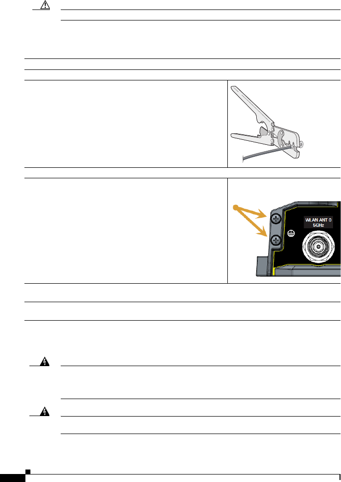
6
Getting started with the Cisco 829 Integrated Services Router
78-100611-01A0
Caution Use at least a 4 mm2 conductor to connect to the external grounding screw.
The ground lug is supplied with the device.
To ground the router to earth ground by using the ground screw, follow these steps:
Connecting DC Power
Warning
When you connect or disconnect the power and/or alarm connector with power applied, an electrical
arc can occur. This could cause an explosion in hazardous area installations. Be sure that all power
is removed from the switch and any other circuits. Be sure that power cannot be accidentally turned
on or verify that the area is nonhazardous before proceeding.
Statement 1058
Warning
Explosion Hazard—The area must be known to be nonhazardous before installing, servicing, or
replacing the unit.
Statement 1082
Step 1 Locate the ground lug in the packaging kit. Store the ground screw for later use.
Step 2 Use a wire stripping tool to strip the 14-16 AWG (2.08-1.31mm²) grounding wire to 0.22 in. (5.56 mm).
Step 3 Insert the ground wire into the ring terminal lug, and using a crimping
tool, crimp the terminal to the wire.
Step 4 Slide the ground screw through the ground lug.
Step 5 Insert the ground screw into one of the two screw positions shown in the
graphic.
Step 6 Use a ratcheting torque screwdriver to tighten the ground screw and ring terminal to the router side panel to 3.5 in-lb
(0.4 N-m). The torque should not exceed 3.5 in-lb (0.4 N-m).
Step 7 Attach the other end of the ground wire to a grounded bare metal surface, such as a ground bus, a grounded DIN
rail, or a grounded bare rack.
332163
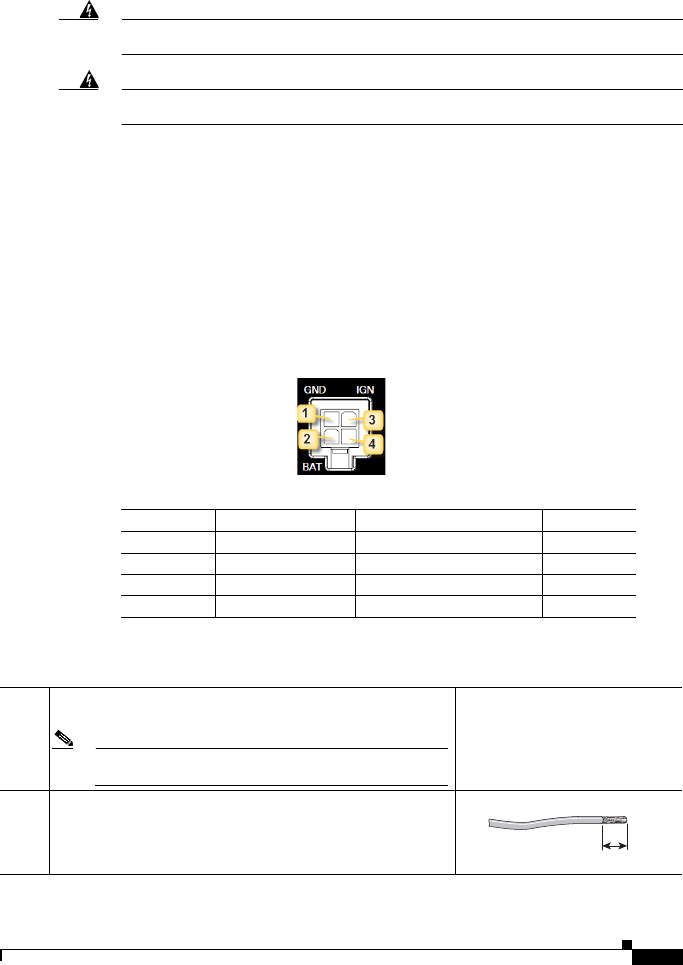
7
Getting started with the Cisco 829 Integrated Services Router
78-100611-01A0
Warning
Explosion Hazard—Substitution of components may impair suitability for Class I, Division 2/Zone 2.
Statement 1083
Warning
Connect the unit only to DC power source that complies with the safety extra-low voltage (SELV)
requirements in IEC 60950 based safety standards.
Statement 1033
Plugs and Pin-Outs
The following is a brief overview of connecting to DC power. Details can be found in the Cisco IR829
Integrated Services Router Hardware Installation Guide and should be understood before beginning. See
Related Documentation, page 3.
The IR829 ships with a DC power accessory kit that contains a 4-pin locking connector and pins to use
for the power connections. Four contacts are supplied, but only three are used. One is a spare.
The power entry receptacle is on the IR829. The pin-outs are shown in Figure 1. Descriptions are shown
in Figure 2.
Figure 1 Power Connector Pin-outs
Figure 2 Power connector Descriptions
To connect DC power:
Pin Number Name Description Color
1 DC In - DC Power Return (GND-) Black
2 Ignition Ignition Input (IGN) Blue
3 DC In + DC Power In (BAT+) Red
4 N/A N/A N/A
Step 1 Identify the DC power source and measure 4 strands of copper wire 16
AWG (1.29mm) long enough to connect to the DC power source.
Note The maximum length of the cable before twisting is 15 feet (4.6
meters).
Step 2 Using an 16-gauge wire-stripping tool, strip each of the wires coming
from each DC-input power source to 0.25 inch (6.3 mm) ± 0.02 inch (0.5
mm). Do not strip more than 0.27 inch (6.8 mm) of insulation from the
wire. Stripping more than the recommended amount of wire can leave
exposed wire from the power connector after installation.
333084
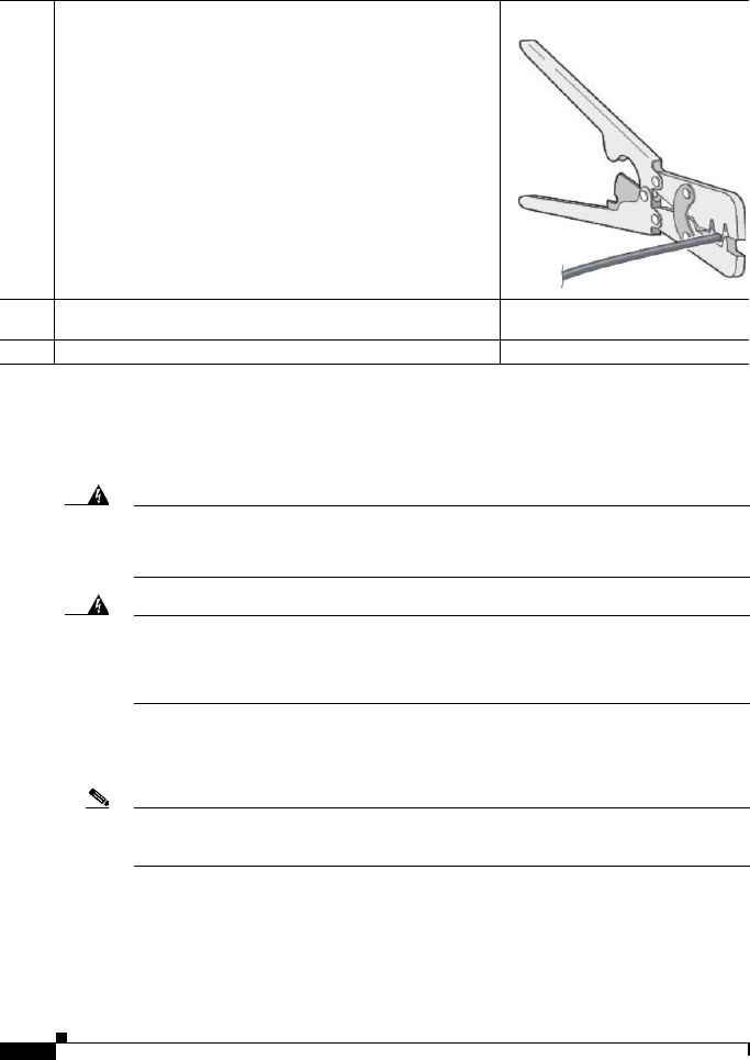
8
Getting started with the Cisco 829 Integrated Services Router
78-100611-01A0
Connecting to the Router Gateway Ports
For hazardous location environments, follow these warnings when connecting to the destination ports
(antenna, serial, Ethernet, and console ports).
Warning
If you connect or disconnect the console cable with power applied to the switch or any device on the
network, an electrical arc can occur. This could cause an explosion in hazardous location
installations. Be sure that power is removed or the area is nonhazardous before proceeding.
Statement 1080
Warning
Do not connect or disconnect cables to the ports while power is applied to the switch or any device
on the network because an electrical arc can occur. This could cause an explosion in hazardous
location installations. Be sure that power is removed from the switch and cannot be accidentally be
turned on, or verify that the area is nonhazardous before proceeding.
Statement 1070
Connecting to the USB Port
Note If you are connecting to the USB port:
- a connection (to the USB port) can only be made in a non-hazardous environment
- the USB port cover must be reinstalled before the router can be deployed in a hazardous environment
Step 3 Using the pins included in the kit, crimp each pin onto a wire.
Step 4 Insert the pins into the power connector, referring to previous figures 1
and 2 for guidance.
Step 5 Plug the connector into the power entry receptacle.

9
Getting started with the Cisco 829 Integrated Services Router
78-100611-01A0
Hazardous Locations Standards and Marking Strings
EMC Information
For EMC and safety information, see the Regulatory Compliance and Safety Information at this URL:
www.cisco.com/go/800
Class A Notice for FCC
Modifying the equipment without Cisco’s authorization may result in the equipment no longer
complying with FCC requirements for Class A digital devices. In that event, your right to use the
equipment may be limited by FCC regulations, and you may be required to correct any interference to
radio or television communications at your own expense.
This equipment has been tested and found to comply with the limits for a Class A digital device, pursuant
to Part 15 of the FCC Rules. Operation is subject to the following two conditions:
1. This device may not cause harmful interference, and
2. This device must accept any interference received, including interference that may cause undesired
operation.
This device operates in the : 5150-5250, 5250-5350, 5470-5725, and 5725-5850 MHz bands and may be
operated indoor or outdoors per FCC guidance.
The following standards were used for the
hazardous locations approvals and certifications:
ANSI/ASA 12.12.01-2013
CAN/CSA C22.2 No. 60079-0-11 Ed. 2
CAN/CSA C22.2 No. 60079-15-12 Ed. 1
CSA C22.2 No. 213-M1987+A11:2013
EN 60079-0:2012
EN 60079-15:2010
IEC 60079-0 6th Edition
IEC 60079-15 4th Edition
UL 60079-0, 5th Ed, 2009-10-21
UL 60079-15, 3rd Ed, 2009-7-17
The following hazardous locations strings are
provided on the router:
Class 1, Div 2, Groups A B C D
Class I, Zone 2, AEx nA IIC T4 Gc
II 3G, Ex nA IIC T4 Gc
DEMKO 15ATEX 1491X
Class 1, Zone 2, AEx nA IIC T4 Gc

10
Getting started with the Cisco 829 Integrated Services Router
78-100611-01A0
This equipment has been tested and found to comply with the limits of a Class A digital device, pursuant
to Part 15 of the FCC Rules. These limits are designed to provide reasonable protection against harmful
interference when the equipment is operated in a residential environment. This equipment generates,
uses, and radiates radio frequency energy, and if not installed and used in accordance with the
instructions, may cause harmful interference. However, there is no guarantee that interference will not
occur. If this equipment does cause interference to radio or television reception, which can be determined
by turning the equipment off and on, the user is encouraged to correct the interference by one of the
following measures:
•Reorient or relocate the receiving antenna.
•Increase separation between the equipment and receiver.
•Connect the equipment to an outlet on a circuit different from which the receiver is connected.
•Consult the dealer or an experienced radio/TV technician.
Caution The Part 15 radio device operates on a non-interference basis with other devices operating at this
frequency when using the integrated antennas. Any changes or modification to the product not expressly
approved by Cisco could void the user's authority to operate this device.
Caution Within the 5.15 to 5.25 GHz and 5.47-5.725 GHz bands, this device is restricted to indoor operations to
reduce any potential for harmful interference to co-channel Mobile Satellite System (MSS) operations.
Industry Canada
Canadian Compliance Statement
Cisco® 829 Industrial Integrated Services Router Model
IR829GW-LTE
Cisco® 829 Industrial Integrated Services Router PIDS
•IR829GW-LTE-VZ-AK9
•IR829GW-LTE-NA-AK9
•IR829GW-LTE-ST-AK9
Industry Canada Certification Number
•2461B-IR829GW-LTE
This Class A Digital apparatus meets all the requirements of the Canadian Interference-Causing
Equipment Regulations.
This device complies with Class A Limits of Industry Canada. Operation is subject to the following two
conditions:
1. This device may not cause harmful interference, and
2. This device must accept any interference received, including interference that may cause undesired
operation.
Cisco® 829 Industrial Integrated Services Routers are certified to the requirements of RSS-210. The use
of this device in a system operating either partially or completely outdoors may require the user to obtain
a license for the system according to the Canadian regulations. For further information, contact your
local Industry Canada office.
This device has been designed to operate with antennas having a maximum gain of 6 dBi. Antennas
having a gain greater than 6 dBi are strictly prohibited for use with this device. The required antenna
impedance is 50 ohms.

11
Getting started with the Cisco 829 Integrated Services Router
78-100611-01A0
To reduce potential radio interference to other users, the antenna type and its gain should be so chosen
that the equivalent isotopically radiated power (EIRP) is not more than that permitted for successful
communication.
Operation in the band 5150-5250 MHz is only for indoor use to reduce the potential for harmful
interference to co-channel mobile satellite systems.
Users are advised that high-power radars are allocated as primary users (i.e. priority users) of the bands
5250-5350 MHz and 5650-5850 MHz and that these radars could cause interference and/or damage to
LE-LAN devices.
European Community, Switzerland, Norway, Iceland, and Liechtenstein
Cisco® 829 Industrial Integrated Services Router PIDS
•IR829GW-LTE-VZ-AK9
•IR829GW-LTE-NA-AK9
•IR829GW-LTE-ST-AK9
Declaration of Conformity with regard to the R&TTE Directive 1999/5/EC & Medical Directive
93/42/EEC
The following standards were applied:
•EMC-EN 301.489-1 v1.9.2; EN 301.489-17 v2.2.1
•Health & Safety-EN60950-1: 2005; EN 50385: 2002
•Radio-EN 300 328 v 1.9.1; EN 301.893 v 1.7.1, EN62311
The conformity assessment procedure referred to in Article 10.4 and Annex III of Directive 1999/5/EC
has been followed.
This device also conforms to the EMC requirements of the Medical Devices Directive 93/42/EEC.
Note This equipment is intended to be used in all EU and EFTA countries. Outdoor use may be restricted to
certain frequencies and/or may require a license for operation. For more details, contact Cisco Corporate
Compliance.
The product carries the CE Mark:
Declaration of Conformity for RF Exposure
This section contains information on compliance with guidelines related to RF exposure.
Generic Discussion on RF Exposure
The Cisco products are designed to comply with the following national and international standards on
Human Exposure to Radio Frequencies:
•US 47 Code of Federal Regulations Part 2 Subpart J
•American National Standards Institute (ANSI) / Institute of Electrical and Electronic Engineers /
IEEE C 95.1 (99)

12
Getting started with the Cisco 829 Integrated Services Router
78-100611-01A0
•International Commission on Non Ionizing Radiation Protection (ICNIRP) 98
•Ministry of Health (Canada) Safety Code 6. Limits on Human Exposure to Radio Frequency Fields
in the range from 3kHz to 300 GHz
•Australia Radiation Protection Standard
To ensure compliance with various national and international Electromagnetic Field (EMF) standards,
the system should only be operated with Cisco approved antennas and accessories.
This Device Meets International Guidelines for Exposure to Radio Waves
The IR829 series device includes a radio transmitter and receiver. It is designed not to exceed the limits
for exposure to radio waves (radio frequency electromagnetic fields) recommended by international
guidelines. The guidelines were developed by an independent scientific organization (ICNIRP) and
include a substantial safety margin designed to ensure the safety of all persons, regardless of age and
health.
As such the systems are designed to be operated as to avoid contact with the antennas by the end user.
It is recommended to set the system in a location where the antennas can remain at least a minimum
distance as specified from the user in accordance to the regulatory guidelines which are designed to
reduce the overall exposure of the user or operator.
The World Health Organization has stated that present scientific information does not indicate the need
for any special precautions for the use of wireless devices. They recommend that if you are interested in
further reducing your exposure then you can easily do so by reorienting antennas away from the user or
placing he antennas at a greater separation distance then recommended.
This Device Meets FCC Guidelines for Exposure to Radio Waves
The IR829 series device includes a radio transmitter and receiver. It is designed not to exceed the limits
for exposure to radio waves (radio frequency electromagnetic fields) as referenced in FCC Part 1.1310.
The guidelines are based on IEEE ANSI C 95.1 (92) and include a substantial safety margin designed to
ensure the safety of all persons, regardless of age and health.
As such the systems are designed to be operated as to avoid contact with the antennas by the end user.
It is recommended to set the system in a location where the antennas can remain at least a minimum
distance as specified from the user in accordance to the regulatory guidelines which are designed to
reduce the overall exposure of the user or operator.
The device has been tested and found compliant with the applicable regulations as part of the radio
certification process.
The US Food and Drug Administration has stated that present scientific information does not indicate
the need for any special precautions for the use of wireless devices. The FCC recommends that if you
are interested in further reducing your exposure then you can easily do so by reorienting antennas away
from the user or placing the antennas at a greater separation distance then recommended or lowering the
transmitter power output.
Separation Distance
MPE Distance Limit
0.63 mW/cm220 cm (7.87 inches) 1.00 mW/cm2
Separation Distance
MPE Distance Limit
0.63 mW/cm220 cm (7.87 inches) 1.00 mW/cm2

13
Getting started with the Cisco 829 Integrated Services Router
78-100611-01A0
This Device Meets the Industry Canada Guidelines for Exposure to Radio Waves
The IR829 series device includes a radio transmitter and receiver. It is designed not to exceed the limits
for exposure to radio waves (radio frequency electromagnetic fields) as referenced in Health Canada
Safety Code 6. The guidelines include a substantial safety margin designed into the limit to ensure the
safety of all persons, regardless of age and health.
As such the systems are designed to be operated as to avoid contact with the antennas by the end user.
It is recommended to set the system in a location where the antennas can remain at least a minimum
distance as specified from the user in accordance to the regulatory guidelines which are designed to
reduce the overall exposure of the user or operator.
Health Canada states that present scientific information does not indicate the need for any special
precautions for the use of wireless devices. They recommend that if you are interested in further reducing
your exposure you can easily do so by reorienting antennas away from the user, placing the antennas at
a greater separation distance than recommended, or lowering the transmitter power output.
Additional Information on RF Exposure
You can find additional information on the subject at the following links:
•Cisco Systems Spread Spectrum Radios and RF Safety white paper at this URL:
http://www.cisco.com/warp/public/cc/pd/witc/ao340ap/prodlit/rfhr_wi.htm
•FCC Bulletin 56: Questions and Answers about Biological Effects and Potential Hazards of Radio
Frequency Electromagnetic Fields
•FCC Bulletin 65: Evaluating Compliance with the FCC guidelines for Human Exposure to Radio
Frequency Electromagnetic Fields
•FCC Bulletin 65C (01-01): Evaluating Compliance with the FCC guidelines for Human Exposure
to Radio Frequency Electromagnetic Fields: Additional Information for Evaluating Compliance
for Mobile and Portable Devices with FCC limits for Human Exposure to Radio Frequency
Emission
You can obtain additional information from the following organizations:
•World Health Organization Internal Commission on Non-Ionizing Radiation Protection at this
URL: www.who.int/emf
•United Kingdom, National Radiological Protection Board at this URL: www.nrpb.org.uk
•Cellular Telecommunications Association at this URL: www.wow-com.com
•The Mobile Manufacturers Forum at this URL: www.mmfai.org
EMC Class A Notices and Warnings
Statement 340—Class A Warning for CISPR22
Separation Distance
MPE Distance Limit
0.63 mW/cm220 cm (7.87 inches) 1.00 mW/cm2
Warnung
Dies ist ein Produkt der Klasse A. Bei der Verwendung dieses Produkts im Haus- oder Wohnungsbereich kann es zu
Funkstörungen kommen. In diesem Fall muss der Benutzer u. U. angemessene Maßnahmen ergreifen.

14
Getting started with the Cisco 829 Integrated Services Router
78-100611-01A0
Cisco and the Cisco logo are trademarks or registered trademarks of Cisco and/or its affiliates in the U.S. and other countries. To view a list of
Cisco trademarks, go to this URL: www.cisco.com/go/trademarks. Third-party trademarks mentioned are the property of their respective owners. The
use of the word partner does not imply a partnership relationship between Cisco and any other company. (1110R)
© 2015 Cisco Systems, Inc. All rights reserved.
Printed in the USA on recycled paper containing 10% postconsumer waste.