Cisco Systems IXMLPWA900 Cisco LoRaWAN Interface Module User Manual

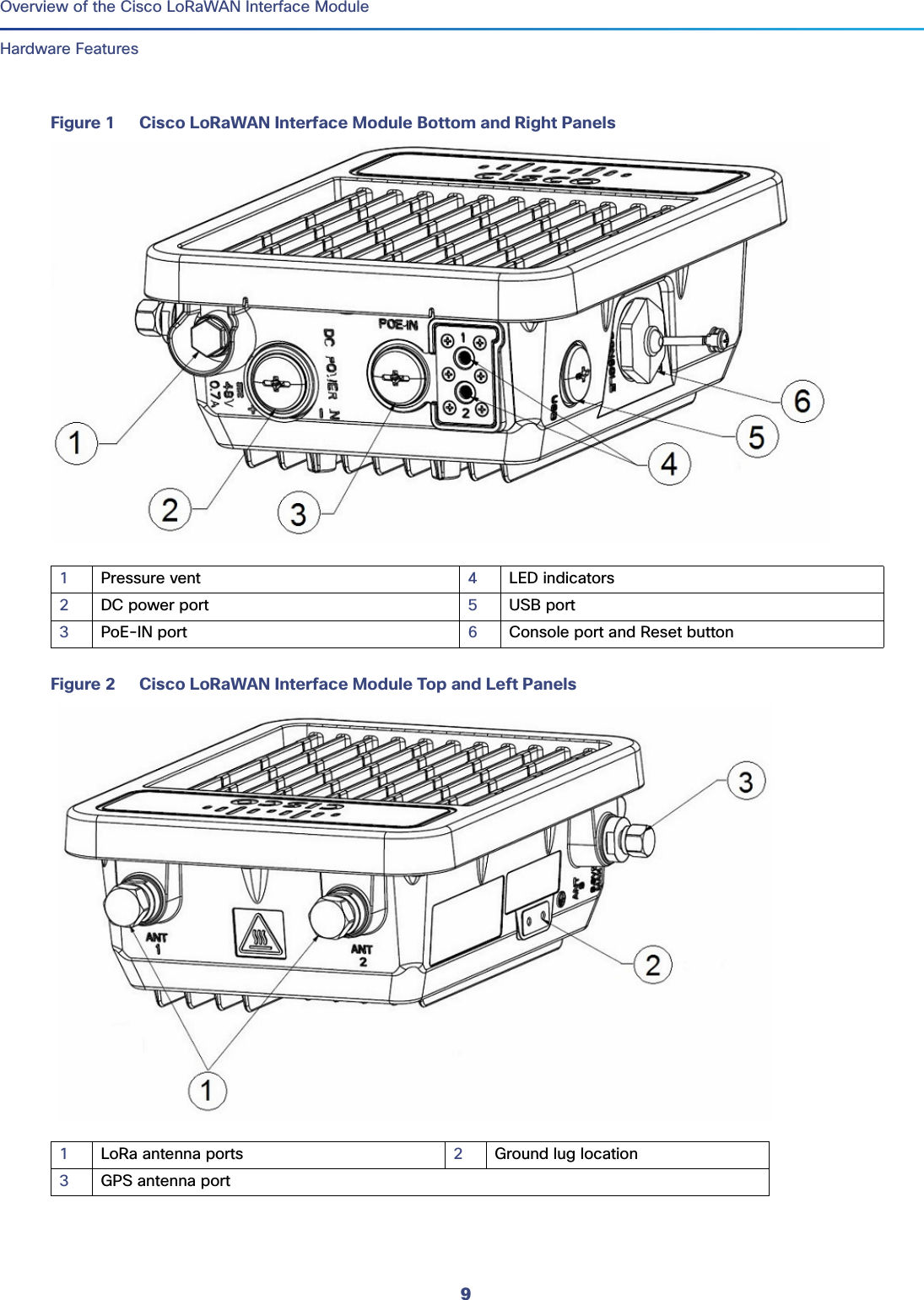
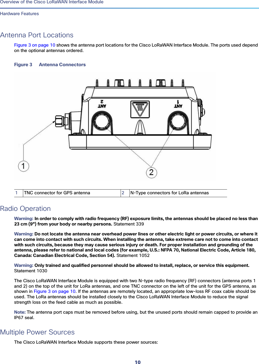
Cisco Systems Inc Cisco LoRaWAN Interface Module

Contents

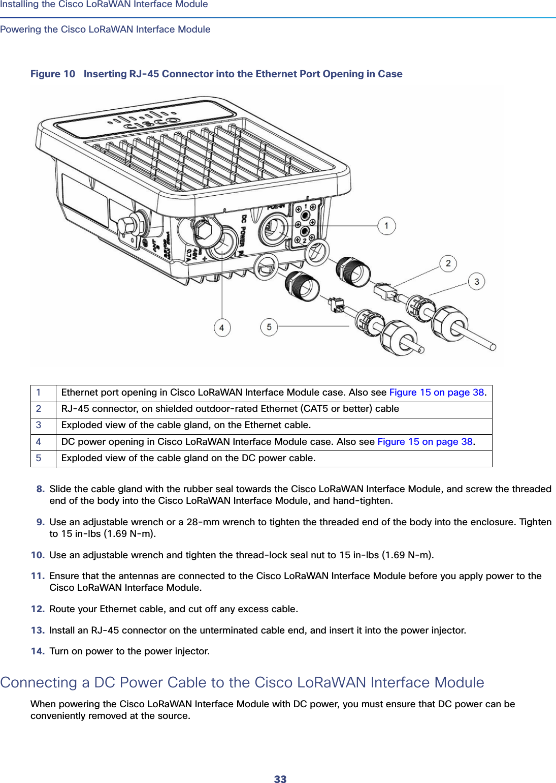
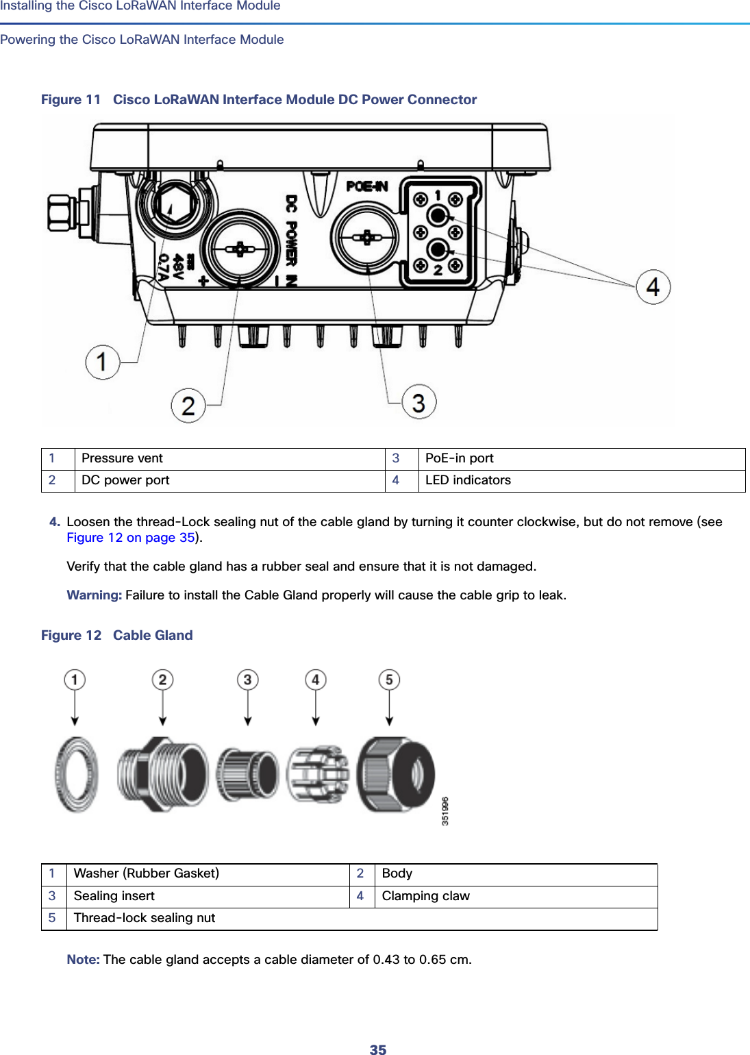
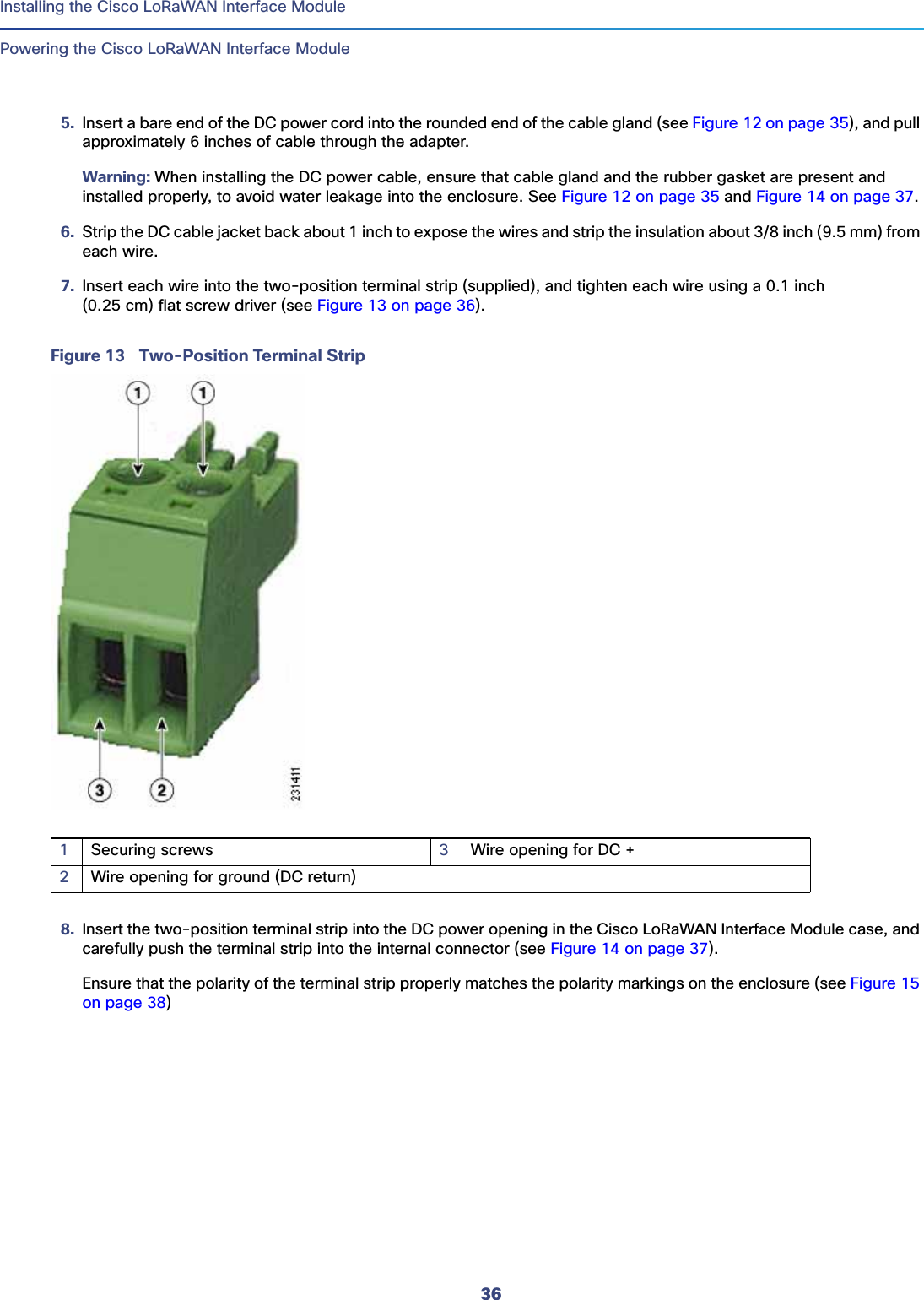
Users Manual (Statement)_rev

1Cisco Systems, Inc. www.cisco.com Cisco LoRaWAN Interface Module Hardware Installation GuideFirst Published:  2016-09-26Last Updated: 2016-10-10THE SPECIFICATIONS AND INFORMATION REGARDING THE PRODUCTS IN THIS MANUAL ARE SUBJECT TO CHANGE WITHOUT NOTICE. ALL STATEMENTS, INFORMATION, AND RECOMMENDATIONS IN THIS MANUAL ARE BELIEVED TO BE ACCURATE BUT ARE PRESENTED WITHOUT WARRANTY OF ANY KIND, EXPRESS OR IMPLIED. USERS MUST TAKE FULL RESPONSIBILITY FOR THEIR APPLICATION OF ANY PRODUCTS.THE SOFTWARE LICENSE AND LIMITED WARRANTY FOR THE ACCOMPANYING PRODUCT ARE SET FORTH IN THE INFORMATION PACKET THAT SHIPPED WITH THE PRODUCT AND ARE INCORPORATED HEREIN BY THIS REFERENCE. IF YOU ARE UNABLE TO LOCATE THE SOFTWARE LICENSE OR LIMITED WARRANTY, CONTACT YOUR CISCO REPRESENTATIVE FOR A COPY.The following information is for FCC compliance of Class A devices: This equipment has been tested and found to comply with the limits for a Class A digital device, pursuant to part 15 of the FCC rules. These limits are designed to provide reasonable protection against harmful interference when the equipment is operated in a commercial environment. This equipment generates, uses, and can radiate radio-frequency energy and, if not installed and used in accordance with the instruction manual, may cause harmful interference to radio communications. Operation of this equipment in a residential area is likely to cause harmful interference, in which case users will be required to correct the interference at their own expense. The following information is for FCC compliance of Class B devices: This equipment has been tested and found to comply with the limits for a Class B digital device, pursuant to part 15 of the FCC rules. These limits are designed to provide reasonable protection against harmful interference in a residential installation. This equipment generates, uses and can radiate radio frequency energy and, if not installed and used in accordance with the instructions, may cause harmful interference to radio communications. However, there is no guarantee that interference will not occur in a particular installation. If the equipment causes interference to radio or television reception, which can be determined by turning the equipment off and on, users are encouraged to try to correct the interference by using one or more of the following measures:Reorient or relocate the receiving antenna.Increase the separation between the equipment and receiver.Connect the equipment into an outlet on a circuit different from that to which the receiver is connected.Consult the dealer or an experienced radio/TV technician for help. Modifications to this product not authorized by Cisco could void the FCC approval and negate your authority to operate the product. The Cisco implementation of TCP header compression is an adaptation of a program developed by the University of California, Berkeley (UCB) as part of UCB’s public domain version of the UNIX operating system. All rights reserved. Copyright © 1981, Regents of the University of California.
2Cisco LoRaWAN Interface Module Hardware Installation Guide NOTWITHSTANDING ANY OTHER WARRANTY HEREIN, ALL DOCUMENT FILES AND SOFTWARE OF THESE SUPPLIERS ARE PROVIDED “AS IS” WITH ALL FAULTS. CISCO AND THE ABOVE-NAMED SUPPLIERS DISCLAIM ALL WARRANTIES, EXPRESSED OR IMPLIED, INCLUDING, WITHOUT LIMITATION, THOSE OF MERCHANTABILITY, FITNESS FOR A PARTICULAR PURPOSE AND NONINFRINGEMENT OR ARISING FROM A COURSE OF DEALING, USAGE, OR TRADE PRACTICE.IN NO EVENT SHALL CISCO OR ITS SUPPLIERS BE LIABLE FOR ANY INDIRECT, SPECIAL, CONSEQUENTIAL, OR INCIDENTAL DAMAGES, INCLUDING, WITHOUT LIMITATION, LOST PROFITS OR LOSS OR DAMAGE TO DATA ARISING OUT OF THE USE OR INABILITY TO USE THIS MANUAL, EVEN IF CISCO OR ITS SUPPLIERS HAVE BEEN ADVISED OF THE POSSIBILITY OF SUCH DAMAGES.Any Internet Protocol (IP) addresses and phone numbers used in this document are not intended to be actual addresses and phone numbers. Any examples, command display output, network topology diagrams, and other figures included in the document are shown for illustrative purposes only. Any use of actual IP addresses or phone numbers in illustrative content is unintentional and coincidental.All printed copies and duplicate soft copies are considered un-Controlled copies and the original on-line version should be referred to for latest version.Cisco has more than 200 offices worldwide. Addresses, phone numbers, and fax numbers are listed on the Cisco website at www.cisco.com/go/offices.© 2016 Cisco Systems, Inc. All rights reserved.
3Cisco Systems, Inc. www.cisco.com ContentsCisco LoRaWAN Interface Module Hardware Installation Guide  . . . . . . . . . . . . . . . . . 1Preface  . . . . . . . . . . . . . . . . . . . . . . . . . . . . . . . . . . . . . . . . . . . . . . . . . . . . . . . . . . . 5Audience  . . . . . . . . . . . . . . . . . . . . . . . . . . . . . . . . . . . . . . . . . . . . . . . . . . . . . . . . . . . . .  5Purpose . . . . . . . . . . . . . . . . . . . . . . . . . . . . . . . . . . . . . . . . . . . . . . . . . . . . . . . . . . . . . .  5Conventions . . . . . . . . . . . . . . . . . . . . . . . . . . . . . . . . . . . . . . . . . . . . . . . . . . . . . . . . . . . 5Related Publications . . . . . . . . . . . . . . . . . . . . . . . . . . . . . . . . . . . . . . . . . . . . . . . . . . . . .  5Overview of the Cisco LoRaWAN Interface Module  . . . . . . . . . . . . . . . . . . . . . . . . . . 7About Cisco LoRaWAN Interface Modules  . . . . . . . . . . . . . . . . . . . . . . . . . . . . . . . . . . . .  7Hardware Models . . . . . . . . . . . . . . . . . . . . . . . . . . . . . . . . . . . . . . . . . . . . . . . . . . . . . . .  7Hardware Features . . . . . . . . . . . . . . . . . . . . . . . . . . . . . . . . . . . . . . . . . . . . . . . . . . . . . .  8Platform Features . . . . . . . . . . . . . . . . . . . . . . . . . . . . . . . . . . . . . . . . . . . . . . . . . . . .  8Connectors . . . . . . . . . . . . . . . . . . . . . . . . . . . . . . . . . . . . . . . . . . . . . . . . . . . . . . . . .  8Antenna Port Locations . . . . . . . . . . . . . . . . . . . . . . . . . . . . . . . . . . . . . . . . . . . . . . .  10Radio Operation  . . . . . . . . . . . . . . . . . . . . . . . . . . . . . . . . . . . . . . . . . . . . . . . . . . . .  10Multiple Power Sources  . . . . . . . . . . . . . . . . . . . . . . . . . . . . . . . . . . . . . . . . . . . . . .  10Ethernet (PoE+) Ports . . . . . . . . . . . . . . . . . . . . . . . . . . . . . . . . . . . . . . . . . . . . . . . .  11Reset Button . . . . . . . . . . . . . . . . . . . . . . . . . . . . . . . . . . . . . . . . . . . . . . . . . . . . . . .  11LEDs . . . . . . . . . . . . . . . . . . . . . . . . . . . . . . . . . . . . . . . . . . . . . . . . . . . . . . . . . . . . .  12Optional Hardware  . . . . . . . . . . . . . . . . . . . . . . . . . . . . . . . . . . . . . . . . . . . . . . . . . .  12Installing the Cisco LoRaWAN Interface Module . . . . . . . . . . . . . . . . . . . . . . . . . . . . 13Unpacking the Device . . . . . . . . . . . . . . . . . . . . . . . . . . . . . . . . . . . . . . . . . . . . . . . . . . .  13Package Contents. . . . . . . . . . . . . . . . . . . . . . . . . . . . . . . . . . . . . . . . . . . . . . . . . . .  13Tools and Hardware . . . . . . . . . . . . . . . . . . . . . . . . . . . . . . . . . . . . . . . . . . . . . . . . . . . .  14Optional Tools and Hardware  . . . . . . . . . . . . . . . . . . . . . . . . . . . . . . . . . . . . . . . . . .  14Optional Tools and Hardware That You Supply . . . . . . . . . . . . . . . . . . . . . . . . . . . . .  14Warnings  . . . . . . . . . . . . . . . . . . . . . . . . . . . . . . . . . . . . . . . . . . . . . . . . . . . . . . . . . . . . 15FCC Caution . . . . . . . . . . . . . . . . . . . . . . . . . . . . . . . . . . . . . . . . . . . . . . . . . . . . . . .  16Industry Canada Statement . . . . . . . . . . . . . . . . . . . . . . . . . . . . . . . . . . . . . . . . . . . . 16Radiation Exposure Statement. . . . . . . . . . . . . . . . . . . . . . . . . . . . . . . . . . . . . . . . . .  16Déclaration d'exposition aux radiations . . . . . . . . . . . . . . . . . . . . . . . . . . . . . . . . . . .  16Safety Information. . . . . . . . . . . . . . . . . . . . . . . . . . . . . . . . . . . . . . . . . . . . . . . . . . . . . .  16FCC Safety Compliance Statement . . . . . . . . . . . . . . . . . . . . . . . . . . . . . . . . . . . . . .  16Safety Precautions  . . . . . . . . . . . . . . . . . . . . . . . . . . . . . . . . . . . . . . . . . . . . . . . . . .  16
4 Installation Guidelines . . . . . . . . . . . . . . . . . . . . . . . . . . . . . . . . . . . . . . . . . . . . . . . . . .   17Mounting the Device . . . . . . . . . . . . . . . . . . . . . . . . . . . . . . . . . . . . . . . . . . . . . . . . . . .   18Installation Options  . . . . . . . . . . . . . . . . . . . . . . . . . . . . . . . . . . . . . . . . . . . . . . . . .   18Mounting Orientation . . . . . . . . . . . . . . . . . . . . . . . . . . . . . . . . . . . . . . . . . . . . . . . .   18Wall Mounting With the Mounting Kit . . . . . . . . . . . . . . . . . . . . . . . . . . . . . . . . . . . .   19Pole Mounting With the Mounting Kit . . . . . . . . . . . . . . . . . . . . . . . . . . . . . . . . . . . .   20Installing Antennas  . . . . . . . . . . . . . . . . . . . . . . . . . . . . . . . . . . . . . . . . . . . . . . . . . . . .   22Supported Antennas . . . . . . . . . . . . . . . . . . . . . . . . . . . . . . . . . . . . . . . . . . . . . . . .   22Safety Precautions when Installing Antennas . . . . . . . . . . . . . . . . . . . . . . . . . . .   23Antenna Connector Locations . . . . . . . . . . . . . . . . . . . . . . . . . . . . . . . . . . . . . . . . .   24Connecting the LoRa Antennas . . . . . . . . . . . . . . . . . . . . . . . . . . . . . . . . . . . . . . . .   24Connecting the GPS Antenna  . . . . . . . . . . . . . . . . . . . . . . . . . . . . . . . . . . . . . . . . .   26Installing a Lightning Arrestor. . . . . . . . . . . . . . . . . . . . . . . . . . . . . . . . . . . . . . . . . .   26Installation Considerations . . . . . . . . . . . . . . . . . . . . . . . . . . . . . . . . . . . . . . . . .   27Installation Notes . . . . . . . . . . . . . . . . . . . . . . . . . . . . . . . . . . . . . . . . . . . . . . . .   27Installing the Lightning Arrestor Outdoors. . . . . . . . . . . . . . . . . . . . . . . . . . . . . .   27Cable for the Lightning Arrestor . . . . . . . . . . . . . . . . . . . . . . . . . . . . . . . . . . . . .   28Grounding the Device . . . . . . . . . . . . . . . . . . . . . . . . . . . . . . . . . . . . . . . . . . . . . . . . . .   28Powering the Cisco LoRaWAN Interface Module . . . . . . . . . . . . . . . . . . . . . . . . . . . . . .   29Connecting a Power Source Equipment. . . . . . . . . . . . . . . . . . . . . . . . . . . . . . . . . .   29Connecting an Ethernet Cable to the Cisco LoRaWAN Interface Module . . . . . . . . .   30Connecting a DC Power Cable to the Cisco LoRaWAN Interface Module. . . . . . . . .   33Technical Specifications for the Cisco LoRaWAN Interface Module. . . . . . . . . . . . . . . . . . . . . . . . . . . . . . . . . . . . 39Cisco LoRaWAN Interface Module Technical Specifications  . . . . . . . . . . . . . . . . . . . . .   39LoRa Antenna Technical Specifications . . . . . . . . . . . . . . . . . . . . . . . . . . . . . . . . . . . . .   39GPS Antenna Technical Specifications  . . . . . . . . . . . . . . . . . . . . . . . . . . . . . . . . . . . . .   40
5  PrefaceAudiencePrefaceAudience This guide is for networking or computer technicians responsible for installing the Cisco LoRaWAN Interface Modules. We assume that you are familiar with the concepts and terminology of Ethernet and local area networking.PurposeThis guide documents the hardware features of the Cisco LoRaWAN Interface Modules. It describes the physical and performance characteristics of the modules, explains how to install a Cisco LoRaWAN Interface Module, and provides troubleshooting information.For configuration information, see the Cisco LoRaWAN Interface Module documentation on Cisco.com. For system requirements, important notes, limitations, open and resolved bugs, and documentation updates, see the product release notes on Cisco.com.ConventionsThis document uses the following conventions and symbols for notes, cautions, and warnings. Note: Means reader take note. Notes contain helpful suggestions or references to materials not contained in this manual.Caution: Means reader be careful. In this situation, you might do something that could result in equipment damage or loss of data.Warning: This warning symbol means danger. You are in a situation that could cause bodily injury. Before you work on any equipment, be aware of the hazards involved with electrical circuitry and be familiar with standard practices for preventing accidents. Use the statement number provided at the end of each warning to locate its translation in the translated safety warnings that accompanied this device. Statement 1071Related PublicationsBefore installing, configuring, or upgrading the Cisco LoRaWAN Interface Module, see the release notes on Cisco.com for the latest information.These documents provide complete information about the Cisco LoRaWAN Interface Module and are available on Cisco.com:Getting Started and Product Document of Compliance for the Cisco LoRaWAN Interface ModuleRelease Notes for IoT Field Network Director, Release 3.1Cisco IOS Release 15.6(3)M - Release Notes for Cisco IR800 Industrial Integrated Services Routers and Cisco 1000 Series Connected Grid RoutersCisco IR800 Integrated Services Router Software Configuration GuideCisco IoT Field Network Director User Guide, Release 3.1.x
6Preface Related PublicationsObtaining Documentation and Submitting a Service RequestFor information on obtaining documentation, using the Cisco Bug Search Tool (BST), submitting a service request, and gathering additional information, see What’s New in Cisco Product Documentation.Toreceivenew and revised Ciscotechnical content directly to your desktop, you can subscribeto theWhat’s New in Cisco Product DocumentationRSS feed. The RSS feeds are a free service.
7Cisco Systems, Inc. www.cisco.com Overview of the Cisco LoRaWAN Interface ModuleThis chapter provides an overview of the Cisco LoRaWAN Interface Module and contains the following sections:About Cisco LoRaWAN Interface Modules, page 7Hardware Models, page 7Hardware Features, page 8About Cisco LoRaWAN Interface ModulesLong Range Wide Area Network (LoRaWAN) is a Low Power Wide Area Network (LPWAN) specification intended for wireless battery operated things in regional, national or global network.LoRaWAN network architecture is typically laid out in a star-of-stars topology in which gateways are transparent bridges relaying messages between end-devices and a central network server in the back end. Gateways are connected to the network server via standard IP connections while end-devices use single-hop wireless communication to one or many gateways. A typical LoRa end-to-end infrastructure comprises the following four layers:LoRa Endpoint—The sensor to equip Semtech LoRa RF module inside and run LoRaWAN protocol to communicate to backend platform.LoRa Gateway—The concentrator tunneling the LoRaWAN MAC frames between an endpoint and a Network Server platform.LoRa Network Server—The central component that handles the LoRaWAN MAC traffic, performing endpoint and gateway management, and LoRaWAN MAC layer security and other functions.Application Server—Data security and application enablement.The Cisco LoRaWAN Interface Module is connected to the Cisco 800 Series Industrial Integrated Services Router via an Ethernet cable with PoE+, to perform as a carrier-grade LoRa gateway.Hardware ModelsTable 1 shows the model numbers (or part numbers) and descriptions for the Cisco LoRaWAN Interface Modules.Table 1 Cisco LoRaWAN Interface Module Model Numbers and DescriptionsModel DescriptionIXM-LPWA-800-16-K9 Cisco interface module for LoRaWAN, IoT extension module series, radio spectrum from 863–870 MHz, 16 LoRa channels, IP67IXM-LPWA-900-16-K9 Cisco interface module for LoRaWAN, IoT extension module series, radio spectrum from 902–928 MHz, 16 LoRa channels, IP67
8Overview of the Cisco LoRaWAN Interface Module Hardware FeaturesHardware FeaturesThis section describes the following hardware features of the Cisco LoRaWAN Interface Module models:Platform Features, page 8Connectors, page 8Antenna Port Locations, page 10Multiple Power Sources, page 10Ethernet (PoE+) Ports, page 11LEDs, page 12Optional Hardware, page 12Optional Hardware, page 12Platform FeaturesThe following lists the hardware platform features for the Cisco LoRaWAN Interface Module:CPU 1.33 GHz, single core1GB DDR4 RAM4GB flash memoryOne RJ45 console port, for manufacturing use onlyOne 10/100 Fast Ethernet RJ45 port, PoE+PD supportedOne USB 2.0 Type A external portExternal Reset buttonExternal DC-In power port, 0.7A, 48VTwo extendable RF antenna N-type connectorOne extendable GPS antenna TNC connectorClass A EMC complianceWall/pole mountConnectorsFigure 1 on page 9 and Figure 2 on page 9 show the Cisco LoRaWAN Interface Module connectors. The illustrations in this document show all available connections for the Cisco LoRaWAN Interface Module. Unused connections are capped with a connector plug to ensure the watertight integrity of the Cisco LoRaWAN Interface Module.
9  Overview of the Cisco LoRaWAN Interface ModuleHardware FeaturesFigure 1 Cisco LoRaWAN Interface Module Bottom and Right PanelsFigure 2 Cisco LoRaWAN Interface Module Top and Left Panels1Pressure vent 4LED indicators2DC power port  5USB port3PoE-IN port 6Console port and Reset button 1LoRa antenna ports 2Ground lug location3GPS antenna port
10Overview of the Cisco LoRaWAN Interface Module Hardware FeaturesAntenna Port LocationsFigure 3 on page 10 shows the antenna port locations for the Cisco LoRaWAN Interface Module. The ports used depend on the optional antennas ordered.Figure 3 Antenna ConnectorsRadio OperationWarning: In order to comply with radio frequency (RF) exposure limits, the antennas should be placed no less than 23 cm (9”) from your body or nearby persons. Statement 339Warning: Do not locate the antenna near overhead power lines or other electric light or power circuits, or where it can come into contact with such circuits. When installing the antenna, take extreme care not to come into contact with such circuits, because they may cause serious injury or death. For proper installation and grounding of the antenna, please refer to national and local codes (for example, U.S.: NFPA 70, National Electric Code, Article 180, Canada: Canadian Electrical Code, Section 54). Statement 1052Warning: Only trained and qualified personnel should be allowed to install, replace, or service this equipment. Statement 1030The Cisco LoRaWAN Interface Module is equipped with two N-type radio frequency (RF) connectors (antenna ports 1 and 2) on the top of the unit for LoRa antennas, and one TNC connector on the left of the unit for the GPS antenna, as shown in Figure 3 on page 10. If the antennas are remotely located, an appropriate low-loss RF coax cable should be used. The LoRa antennas should be installed closely to the Cisco LoRaWAN Interface Module to reduce the signal strength loss on the feed cable as much as possible. Note: The antenna port caps must be removed before using, but the unused ports should remain capped to provide an IP67 seal.Multiple Power SourcesThe Cisco LoRaWAN Interface Module supports these power sources:1TNC connector for GPS antenna 2N-Type connectors for LoRa antennas
11  Overview of the Cisco LoRaWAN Interface ModuleHardware FeaturesPower-over-Ethernet (PoE+, 30W)DC power—48 VDCWarning: Installation of the equipment must comply with local and national electrical codes. Statement 1074Warning: This equipment must be externally grounded using a customer-supplied ground wire before power is applied. Contact the appropriate electrical inspection authority or an electrician if you are uncertain that suitable grounding is available. Statement 366Warning: Do not work on the system or connect or disconnect cables during periods of lightning activity. Statement 1001Warning: Connect the unit only to DC power source that complies with the safety extra-low voltage (SELV) requirements in IEC 60950 based safety standards. Statement 1033Warning: To reduce the risk of fire, use only No. 26 AWG or larger telecommunication line cord. Statement 1023Caution: Do not place the power injector in an unprotected outdoor environment because water could get into the power injector and cause a short circuit and possible fire.Ethernet (PoE+) PortsThe Cisco LoRaWAN Interface Module supports an Ethernet uplink port (PoE-In). The RJ-45 connector (with weatherproofing) links the device to the 10BASE-T or 100BASE-T network. The Ethernet cable is used to send and receive Ethernet data and to optionally supply inline 54-VDC power from the power injector.The Ethernet cable must be a shielded outdoor rated Category 5 (CAT5) or better cable. The Cisco LoRaWAN Interface Module senses the Ethernet and power signals and automatically switches internal circuitry to match the cable connections.Reset ButtonA Cisco LoRaWAN Interface Module that has already been configured can be reset to the manufacturing configuration by pressing the Reset button located at the side of the CONSOLE port on the device.If you press the Reset button and release it in less than 5 seconds, the system will reboot immediately with the last saved configuration.If you press the Reset button and release it after more than 5 seconds, the system will reboot immediately and restore to the factory default.
12Overview of the Cisco LoRaWAN Interface Module Hardware FeaturesLEDsThis section describes the LEDs for the Cisco LoRaWAN Interface Module. See Figure 1 on page 9 for the locations of LED indicators.Optional HardwareDepending on what you ordered, the following optional Cisco LoRaWAN Interface Module hardware may be part of your shipment:Wall/pole mount kit (AIR-ACC1530-PMK1=)DC-IN power adapter jack plug (PLG-PWRJCK=)Grounding lugLoRa Antenna—Omni-directional antenna (ANT-LPWA-DB-O-N=)—Antennas lightning arrestor (ACC-LA-H-NM-NF=)—10-ft low-loss cable assembly with N type connector (AIR-CAB010LL-N=)GPS Antenna—Outdoor GPS antenna with integrated 15-ft cable (ANT-GPS-OUT-TNC=)—Outdoor GPS antenna lightning arrestor (ACC-LA-G-TM-TF=)Note: For more detailed information about the accessories, see the data sheet of Cisco LoRaWAN Interface Module.Table 2 LED DefinitionsLED LED Color DefinitionSystem LED (LED 1) Off Power off or under bootloader modeBlinking green Under the starting kernel (bring up phase)Solid green Normal operation stateBlinking red Failed to get IP addressRegister to IR800 failedSolid red ACT2 check failedLost connection to IR800CPU usage highTemperature highFlash usage highCover openReserved LED (LED 2) Reserved for future use. —
13Cisco Systems, Inc. www.cisco.com Installing the Cisco LoRaWAN Interface ModuleThis chapter describes how to install the Cisco LoRaWAN Interface Module and contains the following sections:Unpacking the Device, page 13Tools and Hardware, page 14Warnings, page 15Safety Information, page 16Installation Guidelines, page 17Mounting the Device, page 18Installing Antennas, page 22Grounding the Device, page 28Powering the Cisco LoRaWAN Interface Module, page 29Caution: The Cisco LoRaWAN Interface Module must be installed by professional networking or computer technicians.Note: For configuration information, refer to the Configuring Virtual-LPWA section of the Cisco IR800 Integrated Services Router Software Configuration Guide on Cisco.com:http://www.cisco.com/c/en/us/support/routers/interface-module-lorawan/products-installation-and-configuration-guides-list.htmlUnpacking the DeviceFollow these steps to unpack the box:1. Open the shipping container and carefully remove the contents. 2. Return all packing materials to the shipping container and save it.3. Ensure that all items listed in the Package Contents are included in the shipment. Check each item for damage. If any item is damaged or missing, notify your authorized Cisco sales representative. Package ContentsEach Cisco LoRaWAN Interface Module package contains the following items:One Cisco LoRaWAN Interface Module (IXM-LPWA-800-16-K9 or IXM-LPWA-900-16-K9)Getting Started and Product Document of Compliance for the Cisco LoRaWAN Interface Module (Part Number 78-100921-01)
14Installing the Cisco LoRaWAN Interface Module Tools and HardwareTools and HardwareThe tools and hardware used to install the Cisco LoRaWAN Interface Module are described in:Optional Tools and Hardware, page 14Optional Tools and Hardware That You Supply, page 14Optional Tools and HardwareDepending on what you ordered, the following optional equipment may be part of your shipment:Wall/pole mount kit (AIR-ACC1530-PMK1=)DC-IN power adapter jack plug (PLG-PWRJCK=)Grounding lugLoRa Antenna—Omni-directional antenna (ANT-LPWA-DB-O-N=)—Antennas lightning arrestor (ACC-LA-H-NM-NF=)—10-ft low-loss cable assembly with N type connector (AIR-CAB010LL-N=)GPS Antenna—Outdoor GPS antenna with integrated 15-ft cable (ANT-GPS-OUT-TNC=)—Outdoor GPS antenna lightning arrestor (ACC-LA-G-TM-TF=)Optional Tools and Hardware That You SupplyTools and materials that are user-supplied are:Ground lug crimping tool (Panduit CT-720 with CD-720-1 die) 6-AWG copper ground wire10 mm open end or box wrench13 mm box-end wrench or socket set, or US standard socket (for example, 1/2")Adjustable wrench with opening up to 33 mm and 28 mm socketLarge flat or Phillips screw driver (for port plugs)Small flat screwdriver for DC power connectorOptional shielded outdoor-rated Ethernet (CAT5 or better) cable with 4.3 to 6.5mm (0.17 to 0.25 inch) diameter to fit the cable gland, for the IP67 and also to allow strength relief on the cable connector insideOptional Ethernet RJ-45 connector and installation toolOptional shielded outdoor-rated DC power cable with 16 AWG to 22 AWG (1.29 to 0.65mm diameter), to match the DC power adapter jack plug (PLG-PWRJCK=)Optional ground rod, as required by local regulationsOptional ladder, power lift, rope, or other tools as required
15  Installing the Cisco LoRaWAN Interface ModuleWarningsWarningsWarning: IMPORTANT SAFETY INSTRUCTIONSMeans danger. You are in a situation that could cause bodily injury. Before you work on any equipment, be aware of the hazards involved with electrical circuitry and be familiar with standard practices for preventing accidents. Use the statement number provided at the end of each warning to locate its translation in the translated safety warnings that accompanied this device. Statement 1071Warning: Before performing any of the following procedures, ensure that power is removed from the DC circuit. Statement 1003Warning: Read the installation instructions before you connect the system to its power source. Statement 1004Warning: This product relies on the building’s installation for short-circuit (overcurrent) protection. Ensure that the protective device is rated not greater than: 2 A. Statement 1005Warning: This unit is intended for installation in restricted access areas. A restricted access area can be accessed only through the use of a special tool, lock and key, or other means of security. Statement 1017Warning: A readily accessible two-poled disconnect device must be incorporated in the fixed wiring.Statement 1022Warning: This equipment must be grounded. Never defeat the ground conductor or operate the equipment in the absence of a suitably installed ground conductor. Contact the appropriate electrical inspection authority or an electrician if you are uncertain that suitable grounding is available. Statement 1024Warning: Only trained and qualified personnel should be allowed to install, replace, or service this equipment. Statement 1030Warning: Ultimate disposal of this product should be handled according to all national laws and regulations. Statement 1040Warning: For connections outside the building where the equipment is installed, the following ports must be connected through an approved network termination unit with integral circuit protection: 10/100 Ethernet Statement 1044Warning: To prevent the system from overheating, do not operate it in an area that exceeds the maximum recommended ambient temperature of: 131°F (55°C) Statement 1047Warning: This equipment is intended to be grounded to comply with emission and immunity requirements. Ensure that the switch functional ground lug is connected to earth ground during normal use. Statement 1064Warning: Installation of the equipment must comply with local and national electrical codes. Statement 1074Warning: Avoid using or servicing any equipment that has outdoor connections during an electrical storm. There may be a risk of electric shock from lightning. Statement 1088Caution: For the device, connect only to an NEC Class 2 power source or limited power source as defined by IEC 60950-1.Warning: This product is designed for specific application and needs to be installed by a qualified personal who has RF and related rule knowledge. The general user shall not attempt to install or change the setting.Warning: The product shall be installed at a location where the radiating antenna can be kept 23 cm from nearby person in normal operation condition to meet regulatory RF exposure requirement.Warning: Use only the antennas which have been approved by the applicant. The non-approved antenna(s) may produce unwanted spurious or excessive RF transmitting power which may lead to the violation of FCC/ISED limit and is prohibited.
16Installing the Cisco LoRaWAN Interface Module Safety InformationNote: The device is suitable for use in environmental air space in accordance with section 300.22.C of the National Electrical Code and sections 2-128, 12-010(3), and 12-100 of the Canadian Electrical Code, Part 1, C22.1. You should not install the power supply or power injector in air handling spaces.Note: Use only with listed ITE equipment.Note: The maximum ambient operating temperature range is –40 to 131°F (–40 to 55°C), plus solar load.Note: The POE source which the unit is intended to connect is IEEE 802.3 at.FCC CautionAny changes or modifications not expressly approved by the party responsible for compliance could void the user's authority to operate this equipment. This transmitter must not be co-located or operating in conjunction with any other antenna or transmitter, except the collocation in accordance with FCC multi-transmitter product guidelines.Industry Canada StatementThis device complies with ISED’s licence-exempt RSSs. Operation is subject to the following two conditions: (1) This device may not cause harmful interference, and (2) this device must accept any interference received, including interference that may cause undesired operation.Le présent appareil est conforme aux CNR d’ ISED applicables aux appareils radio exempts de licence. L’exploitation est autorisée aux deux conditions suivantes : (1) le dispositif ne doit pas produire de brouillage préjudiciable, et (2) ce dispositif doit accepter tout brouillage reçu, y compris un brouillage susceptible de provoquer un fonctionnement indésirable. Radiation Exposure StatementThis equipment complies with FCC and ISED radiation exposure limits set forth for an uncontrolled environment. This equipment should be installed and operated with minimum distance 23 cm between the radiator and your body. Déclaration d'exposition aux radiationsCet équipement est conforme aux limites d'exposition aux rayonnements ISED établies pour un environnement non contrôlé. Cet équipement doit être installé et utilisé avec un minimum de 23 cm de distance entre la source de rayonnement et votre corps.Safety InformationFollow the guidelines in this section to ensure proper operation and safe use of the Cisco LoRaWAN Interface Module.FCC Safety Compliance StatementThe FCC, with its action in ET Docket 96-8, has adopted a safety standard for human exposure to RF electromagnetic energy emitted by FCC-certified equipment. When used with approved Cisco Aironet antennas, Cisco Aironet products meet the uncontrolled environmental limits found in OET-65 and ANSI C95.1, 1991. Proper operation of this radio device according to the instructions in this publication results in user exposure substantially below the FCC recommended limits.Safety PrecautionsWarning: In order to comply with radio frequency (RF) exposure limits, the antennas should be placed no less than 20 cm (8”) from your body or nearby persons. Statement 339
17  Installing the Cisco LoRaWAN Interface ModuleInstallation GuidelinesWarning: Do not work on the system or connect or disconnect cables during periods of lightning activity. Statement 1001Warning: A readily accessible two-poled disconnect device must be incorporated in the fixed wiring. Statement 1022Warning: Only trained and qualified personnel should be allowed to install, replace, or service this equipment. Statement 1030Warning: Connect the unit only to DC power source that complies with the safety extra-low voltage (SELV) requirements in IEC 60950 based safety standards. Statement 1033Warning: When installing or replacing the unit, the ground connection must always be made first and disconnected last. Statement 1046.Warning: Do not locate the antenna near overhead power lines or other electric light or power circuits, or where it can come into contact with such circuits. When installing the antenna, take extreme care not to come into contact with such circuits, because they may cause serious injury or death. For proper installation and grounding of the antenna, please refer to national and local codes (for example, U.S.:NFPA 70, National Electrical Code, Article 810, Canada: Canadian Electrical Code, Section 54). Statement 1052Caution: Before connecting or disconnecting a power cord, you must remove power from the power cord using a suitable service disconnect.For safety and to achieve a good installation, please read and follow these safety precautions:Select your installation site with safety, as well as performance in mind. Remember: electric power lines and phone lines look alike. For safety, assume that any overhead line can kill. Call your electric power company. Tell them your plans, and ask them to come look at your proposed installation. Plan your installation carefully and completely before you begin. Successful raising of a mast or tower is largely a matter of coordination. Each person should be assigned to a specific task and should know what to do and when to do it. One person should be in charge of the operation to issue instructions and watch for signs of trouble.When installing the access point and antennas, remember:—Do not use a metal ladder.—Do not work on a wet or windy day.—Do dress properly—shoes with rubber soles and heels, rubber gloves, long sleeved shirt or jacket.Use a rope to lift the access point. If the assembly starts to drop, get away from it and let it fall. If any part of the antenna system should come in contact with a power line, do not touch it or try to remove it yourself. Call your local power company. They will remove it safely. If an accident should occur, call for qualified emergency help immediately.Installation GuidelinesBecause the Cisco LoRaWAN Interface Module is a radio device, it is susceptible to common causes of interference that can reduce throughput and range. Follow these basic guidelines to ensure the best possible performance:Perform a site survey before beginning the installation.Install the device in an area where structures, trees, or hills do not obstruct radio signals to and from the device.
18Installing the Cisco LoRaWAN Interface Module Mounting the DeviceThe Console-Reset port and the Reset button are under a hex-shaped sealed plug. Inspect the seal of the plug and properly tighten it at the time of installation, and also every time the plug is removed and replaced. Tighten the plug to 15 lbf-in. If you do not tighten the plug properly, it will not meet IP67 criteria, and may lead to water leaking into the unit.Figure 1 Connecting Console Port and USB portIf the DC power port, LAN port, or the PoE-In port is not in use, the port’s covering plug must be tightened to 12.5 in-lbs (1.41 N-m) torque. Otherwise, it may lead to water leaking into the Cisco LoRaWAN Interface Module.To calculate path loss and to determine how far apart to install Cisco LoRaWAN Interface Modules, consult an RF planning expert.Mounting the DeviceThis section provides instructions for installing your access points. Personnel installing the access point must understand wireless Cisco LoRaWAN Interface Modules and bridging techniques and grounding methods. Caution: All installation methods for mounting an Cisco LoRaWAN Interface Module on any wall surface is subject to the acceptance of local jurisdiction.Installation OptionsThe Cisco LoRaWAN Interface Module can be pole or wall mounted by using the mounting kit (AIR-ACC1530-PMK1=).Warning: Only trained and qualified personnel should be allowed to install, replace, or service this equipment. Statement 1030Warning: Installation of the equipment must comply with local and national electrical codes. Statement 1074Mounting OrientationWhen mounting an Cisco LoRaWAN Interface Module on a vertical surface, you must ensure that the Cisco LoRaWAN Interface Module is oriented with the LED indicators pointing down. This positioning allows LEDs to be visible to someone on the ground below the Cisco LoRaWAN Interface Module.
19  Installing the Cisco LoRaWAN Interface ModuleMounting the DeviceYou must also ensure the Cisco LoRaWAN Interface Module is mounted in such a way as to ensure that all antenna ports are accessible for future use.Wall Mounting With the Mounting KitThe mounting kit contains a mounting bracket for wall mounting or pole mounting. You can use the mounting bracket as a template to mark the positions of the mounting holes for your installation. You then install the mounting plate, and attach the Cisco LoRaWAN Interface Module when you are ready. Table 1 lists the materials you will need to provide in addition to the fixed mounting kit.Note: The mounting surface, attaching screws and optional wall anchors must be able to support a 50-lb (22.7 kg) static weight.To mount the Cisco LoRaWAN Interface Module on a vertical wall, follow these instructions:1. Use the mounting bracket as a template to mark four screw hole locations on the mounting surface. See Figure 2 on page 20 for the mounting bracket screw hole locations. Use the bracket mount holes to attach the unit to the wall.Table 1 Material Needed for Vertical Wall MountingMaterials Required In KitGround lug and screws (provided with Cisco LoRaWAN Interface Module) YesOne mount bracket YesFour M6 x 12-mm Hex-head bolts YesCrimping tool for ground lug NoFour wall mounting screws NoFour wall anchors (specified for all material) NoDrill bit for wall anchors NoElectric drill and standard screwdriver No#6 AWG ground wire NoShielded outdoor-rated Ethernet (CAT5 or better) cable with 4.3 to 6.5 mm (0.17 to 0.25 inch) diameter (for IP67 and strength relief)NoGrounding block NoGrounding rod No10-mm box-end wrench or socket set No
20Installing the Cisco LoRaWAN Interface Module Mounting the DeviceFigure 2 Mounting Bracket for Wall or Pole Mounting2. Use four customer-supplied screws and optional screw-anchors to attach the mounting plate to the mounting surface.3. If necessary, use suitable screw anchors and an exterior-grade plywood backboard to mount the Cisco LoRaWAN Interface Module to stucco, cement or drywall.4. Screw an M6 x12 mm bolt into each of the four support bolt holes on the back of the Cisco LoRaWAN Interface Module. Do not screw the bolt all the way in; leave approximately a 1/8” (3.3 mm) space.5. Position the four bolts on the Cisco LoRaWAN Interface Module into the keyhole slots on the mounting bracket. 6. Slide the Cisco LoRaWAN Interface Module down to sit securely in the quick mount slots.7. Using a 10mm wrench, secure the Cisco LoRaWAN Interface Module to the bracket by tightening the bolts to the bracket; torque to 40 in-lbs (4.52 N-m).8. Continue with Grounding the Device. Pole Mounting With the Mounting KitThe mounting kit contains a mounting bracket for wall mounting or pole mounting. This kit can be used to install the Cisco LoRaWAN Interface Module on a pole. It supports metal, wood or fiberglass poles from 2 to 8 inches in diameter.1Quick Mount Keyhole Slots (for the Cisco LoRa Interface use)2Mounting Slots (used with the band clamps)3Bracket Mount Holes (use bolts up to 1/4" or 6 mm in diameter)
21  Installing the Cisco LoRaWAN Interface ModuleMounting the DeviceTo mount the Cisco LoRaWAN Interface Module onto a vertical pole, follow these steps:1. Select a mounting location on the pole to mount the Cisco LoRaWAN Interface Module. You can attach the Cisco LoRaWAN Interface Module to any pole with a diameter from 2 to 8 inches (5.1 to 20.1 cm).2. Determine which size of band clamp is needed based on the pole diameter. Slide the two clamps through the top and bottom set of mounting slots (see Figure 3 on page 22) and mount the bracket to the pole.3. Wrap the band clamps around the pole and slide them into the second set of top and bottom mounting slots on the bracket. Lightly tighten the clamps. Only tighten them enough to keep the bracket from sliding down the pole.4. Screw an M6 bolt into each of the four bolt holes on the back side of the Cisco LoRaWAN Interface Module. Do not screw the bolt in all the way. Leave a gap of about 1/8" (3.3mm).5. Position the four bolts on the Cisco LoRaWAN Interface Module into the bracket keyhole slots. Check to be sure that the Cisco LoRaWAN Interface Module is properly seated in the slots.(See Figure 3 on page 22)6. The Cisco LoRaWAN Interface Module should be positioned with the LEDs on the bottom to allow viewing from the ground.7. Using a 10mm wrench, tighten the four bolts that connect the Cisco LoRaWAN Interface Module to the bracket to a torque of 40 in-lbs (4.52 N-m). 8. Locate the Cisco LoRaWAN Interface Module to its final position. Tighten the band clamps with the wrench so that the Cisco LoRaWAN Interface Module does not slide on the pole. Be sure that the clamps are tight enough that the Cisco LoRaWAN Interface Module does not move.9. Continue with Grounding the Device. Table 2 Materials Needed for Vertical Pole MountingMaterials Required In KitOne mount bracket YesFour M6 x12mm hex head bolts YesTwo stainless steel band clamps (adjustable 2"–5", 51–127 mm) YesTwo stainless steel band clamps (adjustable 5"–8", 127–203 mm) Yes10 mm box-end wrench NoShielded outdoor-rated Ethernet (CAT5 or better) cable with 4.3 to 6.5 mm (0.17 to 0.25 inch) diameter (for IP67 and strength relief)NoGround lug (provided with the Cisco LoRaWAN Interface Module) YesGround block and rod NoCrimping tool for ground lug No#6 AWG ground wire No
22Installing the Cisco LoRaWAN Interface Module Installing AntennasFigure 3 Cisco LoRaWAN Interface Module and Fixed Mount Kit Installed on a PoleInstalling AntennasThe Cisco LoRaWAN Interface Module is equipped with two N-type radio frequency (RF) connectors (antenna ports 1 and 2) on the top of the unit for LoRa antennas, and one TNC connector on the left of the unit for the GPS antenna, as shown in Figure 4 on page 24. The following topics are described in this section:Supported Antennas, page 22Antenna Connector Locations, page 24Connecting the LoRa Antennas, page 24Connecting the GPS Antenna, page 26Installing a Lightning Arrestor, page 26Supported AntennasThe following antennas are supported by the Cisco LoRaWAN Interface Module:1Metal Band Strap 2Mounting Slots3Pole
23  Installing the Cisco LoRaWAN Interface ModuleInstalling AntennasLoRa AntennasAntenna (ANT-LPWA-DB-O-N=)Lightning arrestor (ACC-LA-H-NM-NF=)Cable (AIR-CAB010LL-N=)GPS AntennaAntenna and cable (ANT-GPS-OUT-TNC=)Lightning arrestor (ACC-LA-G-TM-TF=)Safety Precautions when Installing AntennasWarning: Do not locate the antenna near overhead power lines or other electric light or power circuits, or where it can come into contact with such circuits. When installing the antenna, take extreme care not to come into contact with such circuits, as they may cause serious injury or death. For proper installation and grounding of the antenna, please refer to national and local codes (e.g. U.S.: NFPA 70, National Electrical Code, Article 810, Canada: Canadian Electrical Code, Section 54). Statement 2801. Before you install an antenna, contact your Cisco account representative to explain which mounting method to use for the size and type of antenna that you are about to install.2. Select your installation site with safety, as well as performance, in mind. Remember that electric power lines and phone lines look alike. For your safety, assume that any overhead line can kill you.3. Contact your electric power company. Tell them your plans and ask them to come look at your proposed installation.4. Plan your installation carefully and completely before you begin. Each person involved in an installation should be assigned to a specific task and should know what to do and when to do it. One person should be in charge of the operation to issue instructions and watch for signs of trouble.5. When installing your antenna, follow these guidelines:—Do not use a metal ladder.—Do not work on a wet or windy day.—Do dress properly—wear shoes with rubber soles and heels, rubber gloves, and a long-sleeved shirt or jacket.6. If the assembly starts to drop, move away from it and let it fall. Because the antenna, mast, cable, and metal guy wires are all excellent conductors of electrical current, even the slightest touch of any of these parts to a power line completes an electrical path through the antenna and the installer.7. If any part of the antenna system should come in contact with a power line, do not touch it or try to remove it yourself. Call your local power company to have it removed safely.8. If an accident should occur with the power lines, call for qualified emergency help immediately.Note: The antenna port caps must be removed before using, but the unused ports should remain capped to provide an IP67 seal. All port or antenna connection must be terminated by an IP67 rated cap or cable.
24Installing the Cisco LoRaWAN Interface Module Installing AntennasAntenna Connector LocationsThe Cisco LoRaWAN Interface Module is equipped with two N-type radio frequency (RF) connectors (antenna ports 1 and 2) on the top of the unit for LoRa antennas, and one TNC connector on the left of the unit for the GPS antenna, as shown in Figure 4 on page 24. The LoRa antennas should be connected to the chassis via an appropriate low-loss RF coax cable, for the Cisco LoRaWAN Interface Module to work properly. The LoRa antennas should be installed closely to the Cisco LoRaWAN Interface Module to reduce the signal strength loss on the feed cable as much as possible. Note: Refer to the data sheet for the antenna specifications.Note: The antenna port caps must be removed before using, but the unused ports should remain capped and hand tighted (not too much) to provide an IP67 seal. All port or antenna connection must be terminated by an IP67 rated cap or cable.Figure 4 Antenna ConnectorsConnecting the LoRa AntennasThe LoRa antennas should be connected to the chassis via an appropriate low-loss RF coax cable, for the Cisco LoRaWAN Interface Module to work properly. The LoRa antennas should be installed closely to the Cisco LoRaWAN Interface Module to reduce the signal strength loss on the feed cable as much as possible. The antennas must be installed at half a wavelength apart from each other.1TNC connector for GPS antenna 2N-Type connectors for LoRa antennas
25  Installing the Cisco LoRaWAN Interface ModuleInstalling AntennasFigure 5 on page 25 shows the installation of a LoRa antenna.Figure 5 Connecting the LoRa Antenna1LoRa antenna 3N-Type connectors for LoRa antennas2LoRa antenna cable
26Installing the Cisco LoRaWAN Interface Module Installing AntennasConnecting the GPS AntennaFigure 6 on page 26 shows the installation of the GPS antenna.Figure 6 Connecting the GPS AntennaNote: For more information about the GPS antenna and the mounting instructions, see the Cisco GPS Antenna chapter of the Connected Grid Antennas Installation Guide.Installing a Lightning ArrestorOvervoltage transients can be created through lightning static discharges, switch processes, direct contact with power lines, or through earth currents. The Cisco lightning arrestor limits the amplitude and duration of disturbing interference voltages and improves the over voltage resistance of in-line equipment, systems, and components. A lightning arrestor installed according to these mounting instructions balances the voltage potential, thus preventing inductive interference to parallel signal lines within the protected system.1GPS antenna and mount bracket 3TNC connector for GPS antenna2GPS antenna cable
27  Installing the Cisco LoRaWAN Interface ModuleInstalling AntennasInstallation ConsiderationsCisco recommends that you bulkhead mount the lightning arrestor so it can be installed as a wall-feed through on the wall of the protected space.The importance of obtaining a good ground and bonding connection cannot be overstressed. Consider these points when grounding the lightning arrestor:Connect the lightning arrestor components directly to the grounding point.The contact points of the ground connection must be clean and free of dust and moisture.Tighten threaded contacts to the torque specified by the manufacturer.Installation NotesThis lightning arrestor is designed to be installed between the antenna cable that is attached to an outdoor antenna and the Cisco Aironet wireless device. You can install the lightning arrestor either indoors or outdoors. It can be connected directly to a wireless device having an external N connector. It can also be mounted inline or as a feed-through. Feed-through installations require 5/8 in. (16 mm) hole to accommodate the lightning arrestor.This lightning arrestor is part of a lightning arrestor kit. The kit contains a lightning arrestor and a grounding lug.When you install the lightning arrestor, follow the regulations or best practices applicable to lightning protection installation in your local area.Installing the Lightning Arrestor OutdoorsIf you install the lightning arrestor outdoors, use the supplied ground lug and a #6 stranded copper wire to connect it to a good earth ground, such as a ground rod. The connection should be as short as possible.
28Installing the Cisco LoRaWAN Interface Module Grounding the DeviceFigure 7 Lightning Arrestor DetailsCable for the Lightning ArrestorCoaxial cable loses efficiency as the frequency increases, resulting in signal loss. The cable should be kept as short as possible because cable length also determines the amount of signal loss (the longer the run, the greater the loss).Cisco recommends a high-quality, low-loss cable for use with the lightning arrestor.Grounding the DeviceThe Cisco LoRaWAN Interface Module must be grounded before connecting power.Warning: This equipment must be externally grounded using a customer-supplied ground wire before power is applied. Contact the appropriate electrical inspection authority or an electrician if you are uncertain that suitable grounding is available. Statement 366Warning: Installation of the equipment must comply with local and national electrical codes. Statement 1074In all outdoor installations and when powering the access point with AC power, you must follow these instructions to properly ground the case:1. If using insulated 6-AWG copper ground wire, strip the insulation as required for the grounding lug.1Nut 4#6 stranded copper wire2Lockwasher 5Unprotected side (to antenna)3Ground lug 6Protected side (to wireless device)
29  Installing the Cisco LoRaWAN Interface ModulePowering the Cisco LoRaWAN Interface Module2. Use the appropriate crimping tool to crimp the bare 6-AWG copper ground wire to the supplied grounding lug.Note: The grounding lug and hardware used must comply with local and national electrical codes.3. Connect the grounding lug to the device grounding screw holes using the supplied two Phillips head screws (M4 x10 mm) with lock washers. Tighten the grounding screw to 22 to 24 in-lbs (2.49 to 2.71 N-m). 4. If necessary, strip the other end of the ground wire and connect it to a reliable earth ground, such as a grounding rod or an appropriate grounding point on a metal pole that is grounded (see Figure 3 on page 22).Powering the Cisco LoRaWAN Interface ModuleWarning: Installation of the equipment must comply with local and national electrical codes. Statement 1074Warning: This equipment must be externally grounded using a customer-supplied ground wire before power is applied. Contact the appropriate electrical inspection authority or an electrician if you are uncertain that suitable grounding is available. Statement 366Warning: Do not work on the system or connect or disconnect cables during periods of lightning activity. Statement 1001The Cisco LoRaWAN Interface Module supports these power sources:DC power – 48 VDCPower-over-Ethernet (PoE+, 30W)The Cisco LoRaWAN Interface Module can be powered via the PoE+ input from an in-line power injector or a suitably powered switch port. Caution: Do not place the power injector in an unprotected outdoor environment because water could get into the power injector and cause a short circuit and possible fire.Warning: Connect the unit only to DC power source that complies with the Safety Extra-Low Voltage (SELV) requirements in IEC 60950 based safety standards Statement 1033Connecting a Power Source EquipmentThe Cisco LoRaWAN Interface Module supports the Power Source Equipment (PSE) which is IEEE 802.3at compatible.Warning: To reduce the risk of fire, use only No. 26 AWG or larger telecommunication line cord. Statement 1023The power injector provides 54 VDC to the Cisco LoRaWAN Interface Module over the Ethernet cable and supports a total end-to-end Ethernet cable length of 100 m (328 ft) from the switch to the Cisco LoRaWAN Interface Module. When your Cisco LoRaWAN Interface Module is powered by an optional power injector, follow these steps to complete the installation: 1. Before applying PoE to the Cisco LoRaWAN Interface Module, ensure that the Cisco LoRaWAN Interface Module is grounded (see Grounding the Device).2. Review Table 1 on page 19 and Table 2 on page 21 to identify the components needed for the installation.3. Connect a CAT5 or better Ethernet cable from your wired LAN network to the power injector.Note: The installer is responsible for ensuring that powering the Cisco LoRaWAN Interface Module from this type of power injector is allowed by local and national safety and telecommunications equipment standards.
30Installing the Cisco LoRaWAN Interface Module Powering the Cisco LoRaWAN Interface Module4. Ensure that the antennas are connected and that a ground is attached to the Cisco LoRaWAN Interface Module before you apply power to the Cisco LoRaWAN Interface Module.5. Connect a shielded outdoor-rated Ethernet (CAT5 or better) cable between the power injector and the PoE-in connector of the Cisco LoRaWAN Interface Module (see Figure 8 on page 31).6. Connect the Ethernet cable to the Cisco LoRaWAN Interface Module PoE-In port (see Connecting an Ethernet Cable to the Cisco LoRaWAN Interface Module).Connecting an Ethernet Cable to the Cisco LoRaWAN Interface Module You need to supply these tools and materials:Shielded outdoor-rated Ethernet (CAT5 or better) cable with 4.3 to 6.5 mm (0.17 to 0.25 inch) diameter (for IP67 and strength relief)RJ-45 connector and installation toolAdjustable Wrench or 28 mm box wrenchLarge Phillips or Flat Blade screwdriverTo connect the shielded Ethernet cable to the Cisco LoRaWAN Interface Module, follow these steps:1. Disconnect power to the power injector, and ensure all power sources to the Cisco LoRaWAN Interface Module are turned off.Warning: This unit might have more than one power supply connection. All connections must be removed to de-energize the unit. Statement 10282. Ensure a 6 AWG ground wire is connected to the Cisco LoRaWAN Interface Module (see Grounding the Device).3. Use a large Phillips or Flat Blade screw driver to remove the Ethernet connector plug from the Cisco LoRaWAN Interface Module. Do not discard plug and rubber seal unless you are certain that the port will not have to be re-plugged (see Figure 8 on page 31 for the location).
31  Installing the Cisco LoRaWAN Interface ModulePowering the Cisco LoRaWAN Interface ModuleFigure 8 LEDs Shown on the Bottom of the Cisco LoRaWAN Interface Module4. Loosen the Thread-Lock sealing nut of the cable gland by turning it counter clockwise, but do not remove it (see Figure 9).Note: Verify that the cable gland has a rubber seal and ensure that it is not damaged.Warning: Failure to install the cable gland and rubber gasket properly will cause the cable grip to leak.1Pressure vent 3PoE-in port2DC power port  4LED indicators
32Installing the Cisco LoRaWAN Interface Module Powering the Cisco LoRaWAN Interface ModuleFigure 9 Cable Gland5. Insert the unterminated end of the Ethernet cable through the sealing nut end of the cable gland (see Figure 9 on page 32), and pull several inches of cable through the adapter.6. Install an RJ-45 connector on the unterminated end of the Ethernet cable using your Ethernet cable installation tool.Warning: To reduce the risk of fire, use only No. 26 AWG or larger telecommunication line cord. Statement 1023Warning: When installing the RJ-45 connector, ensure that cable gland and the rubber gasket are present and installed properly, to avoid water leakage into the enclosure. See Figure 9 on page 32 and Figure 10 on page 33.7. Carefully insert the RJ-45 cable connector into the Ethernet port opening on the Cisco LoRaWAN Interface Module, and connect to the internal Ethernet connector (see Figure 10 on page 33). 1Washer (Rubber Gasket) 2Body3Sealing insert 4Clamping claw5Thread-lock sealing nut
33  Installing the Cisco LoRaWAN Interface ModulePowering the Cisco LoRaWAN Interface ModuleFigure 10 Inserting RJ-45 Connector into the Ethernet Port Opening in Case8. Slide the cable gland with the rubber seal towards the Cisco LoRaWAN Interface Module, and screw the threaded end of the body into the Cisco LoRaWAN Interface Module, and hand-tighten.9. Use an adjustable wrench or a 28-mm wrench to tighten the threaded end of the body into the enclosure. Tighten to 15 in-lbs (1.69 N-m).10. Use an adjustable wrench and tighten the thread-lock seal nut to 15 in-lbs (1.69 N-m).11. Ensure that the antennas are connected to the Cisco LoRaWAN Interface Module before you apply power to the Cisco LoRaWAN Interface Module.12. Route your Ethernet cable, and cut off any excess cable.13. Install an RJ-45 connector on the unterminated cable end, and insert it into the power injector. 14. Turn on power to the power injector.Connecting a DC Power Cable to the Cisco LoRaWAN Interface Module When powering the Cisco LoRaWAN Interface Module with DC power, you must ensure that DC power can be conveniently removed at the source. 1Ethernet port opening in Cisco LoRaWAN Interface Module case. Also see Figure 15 on page 38.2RJ-45 connector, on shielded outdoor-rated Ethernet (CAT5 or better) cable3Exploded view of the cable gland, on the Ethernet cable.4DC power opening in Cisco LoRaWAN Interface Module case. Also see Figure 15 on page 38.5Exploded view of the cable gland on the DC power cable.
34Installing the Cisco LoRaWAN Interface Module Powering the Cisco LoRaWAN Interface ModuleWarning: A readily accessible two-poled disconnect device must be incorporated in the fixed wiring. Statement 1022Warning: Connect the unit only to DC power source that complies with the safety extra-low voltage (SELV) requirements in IEC 60950 based safety standards. Statement 1033To connect a DC power cable, you need to supply these tools and material: Shielded outdoor-rated and twisted pair (min 5 tpf) DC power cable (minimum 22 AWG and maximum 16 AWG to fit the DC plug, and big enough to compensate the loss for length or heat) with outside cable diameter of 4.3 mm to 6.5 mmAdjustable or open-end wrenchSmall flat screw driverTwo-pin DC power connector (PLG-PWRJCK=, Cisco supplied)To connect the DC power cable to the Cisco LoRaWAN Interface Module, follow these steps:1. Before connecting DC power to the Cisco LoRaWAN Interface Module, ensure that the ground is connected to the Cisco LoRaWAN Interface Module (see Grounding the Device).2. Turn off all power sources to the Cisco LoRaWAN Interface Module, including the DC power source.Warning: This unit might have more than one power supply connection. All connections must be removed to de-energize the unit. Statement 1028Caution: When installing DC power to the Cisco LoRaWAN Interface Module, always connect the device end of the cable FIRST. When removing the DC power connector, always disconnect the device end of the cable LAST. 3. Use a large Phillips or Flat Blade screw driver to remove the DC power connector plug from the Cisco LoRaWAN Interface Module. Do not discard plug and rubber seal unless you are certain that the port will not have to be re-plugged. (see Figure 11 on page 35 for the location of the DC power connector).
35  Installing the Cisco LoRaWAN Interface ModulePowering the Cisco LoRaWAN Interface ModuleFigure 11 Cisco LoRaWAN Interface Module DC Power Connector 4. Loosen the thread-Lock sealing nut of the cable gland by turning it counter clockwise, but do not remove (see Figure 12 on page 35).Verify that the cable gland has a rubber seal and ensure that it is not damaged.Warning: Failure to install the Cable Gland properly will cause the cable grip to leak.Figure 12 Cable GlandNote: The cable gland accepts a cable diameter of 0.43 to 0.65 cm.1Pressure vent 3PoE-in port2DC power port  4LED indicators1Washer (Rubber Gasket) 2Body3Sealing insert 4Clamping claw5Thread-lock sealing nut
36Installing the Cisco LoRaWAN Interface Module Powering the Cisco LoRaWAN Interface Module5. Insert a bare end of the DC power cord into the rounded end of the cable gland (see Figure 12 on page 35), and pull approximately 6 inches of cable through the adapter.Warning: When installing the DC power cable, ensure that cable gland and the rubber gasket are present and installed properly, to avoid water leakage into the enclosure. See Figure 12 on page 35 and Figure 14 on page 37.6. Strip the DC cable jacket back about 1 inch to expose the wires and strip the insulation about 3/8 inch (9.5 mm) from each wire.7. Insert each wire into the two-position terminal strip (supplied), and tighten each wire using a 0.1 inch(0.25 cm) flat screw driver (see Figure 13 on page 36).Figure 13 Two-Position Terminal Strip8. Insert the two-position terminal strip into the DC power opening in the Cisco LoRaWAN Interface Module case, and carefully push the terminal strip into the internal connector (see Figure 14 on page 37).Ensure that the polarity of the terminal strip properly matches the polarity markings on the enclosure (see Figure 15 on page 38)1Securing screws  3Wire opening for DC + 2Wire opening for ground (DC return)
37  Installing the Cisco LoRaWAN Interface ModulePowering the Cisco LoRaWAN Interface ModuleFigure 14 Inserting the Terminal Strip into the DC Power Opening in the Cisco LoRaWAN Interface Module Case1Ethernet port opening in Cisco LoRaWAN Interface Module case. Also see Figure 15 on page 38.2RJ-45 connector, on shielded outdoor-rated Ethernet (CAT5 or better) cable3Exploded view of the cable gland, on the Ethernet cable.4DC power opening in Cisco LoRaWAN Interface Module case. Also see Figure 15 on page 38.5Exploded view of the cable gland on the DC power cable.
38Installing the Cisco LoRaWAN Interface Module Powering the Cisco LoRaWAN Interface ModuleFigure 15 DC Power Port and Ethernet Port Opening in the Cisco LoRaWAN Interface Module Case9. Slide the cable gland with the rubber seal towards the Cisco LoRaWAN Interface Module, and screw the threaded end of the body into the Cisco LoRaWAN Interface Module, and hand-tighten.10. Use an adjustable wrench, a 28-mm wrench to tighten the threaded end of the body to 15 in-lbs (1.69 N-m).11. Use an adjustable wrench and tighten the thread-lock seal nut to 15 in-lbs (1.69 N-m).12. Ensure that the antennas are connected to the Cisco LoRaWAN Interface Module before you apply power to the Cisco LoRaWAN Interface Module.13. Turn on the DC power at the designated circuits.
39  Technical Specifications for the Cisco LoRaWAN Interface ModuleCisco LoRaWAN Interface Module Technical SpecificationsTechnical Specifications for the Cisco LoRaWAN Interface ModuleThis chapter contains the following technical specifications:Cisco LoRaWAN Interface Module Technical Specifications, page 39LoRa Antenna Technical Specifications, page 39GPS Antenna Technical Specifications, page 40Cisco LoRaWAN Interface Module Technical SpecificationsTable 1 lists the technical specifications for the Cisco LoRaWAN Interface Module. LoRa Antenna Technical SpecificationsTable 2 lists the technical specifications for the LoRa antenna ANT-LPWA-DB-O-N. Table 1 Cisco LoRaWAN Interface Module Technical SpecificationsOperating temperature -40 to 131°F (-40 to 55°C), plus solar load Storage temperature -40 to +85°CRelative humidity 5% to 95% Non-condensingIngress protection IP67Size 281 x 263 x 105 mmAltitude Operational—13,800 feet (4206 meters)Non-operational—15,000 feet (4572 meters)Wind resistance Up to 100 MPH - sustainedUp to 165 MPH - gustsTable 2 Cisco LoRa Antenna Technical SpecificationsFrequency band 863 – 928 MHzImpedance 50 OhmVSWR =< 1.5Peak Gain 6 dBi, Omni directionalHalf power beam width H:360°; V:25°Polarization VerticalMount Pole, WallOperating temperature -40 to 158°F (-40 to 70°C)Ingress protection IP67Operating altitude 10,000 feetWind resistance Up to 100 MPH - sustainedUp to 165 MPH - gusts
40Technical Specifications for the Cisco LoRaWAN Interface Module GPS Antenna Technical SpecificationsGPS Antenna Technical SpecificationsTable 3 lists the technical specifications for the GPS antenna ANT-GPS-OUT-TNC. Connector N TypeDefault cable length 10-ft Lightning Protection DC GroundTable 2 Cisco LoRa Antenna Technical Specifications (continued)Table 3 GPS Antenna Technical SpecificationsType Patch, active Environment OutdoorHeight 3.2 in. (8.13 cm)Width (maximum, at base) 1.75 in. (4.45 cm)Operating frequency range 1575. 42 MHzImpedance 50 ohm, nominalVSWR =< 2.0Peak Gain 4 dBi Omni directionalMinimum gain 1 dBi @ 10-degrees elevationPattern type HemisphericalPolarization  Circular RHCPLNA gain 25 dB +/-2 dB, DC voltage: 3 to 5 VDCOut-of-band attenuation 60 dB min. at 1575 +/- 50 MHzCurrent draw 20 mA max. @ 3.3 VDC +/- .3 VDCOperating temperature -40 to 185°F (-40 to 85°C)Wind resistance 165 MPHConnector Right-angle MCX (m)Compliance ROHS

Navigation menu