Cisco Systems OFDM-MMDS2 Point to Point wireless data link User Manual alph6030
Cisco Systems Inc Point to Point wireless data link alph6030
UserManual.wiki
>
Cisco Systems
>
OFDM MMDS2 User Manual
Installation manual
Navigation menu
Upload a User Manual
Namespaces
Wiki Guide
HTML
PDF
Info
Views
User Manual
Discussion / Help
Navigation
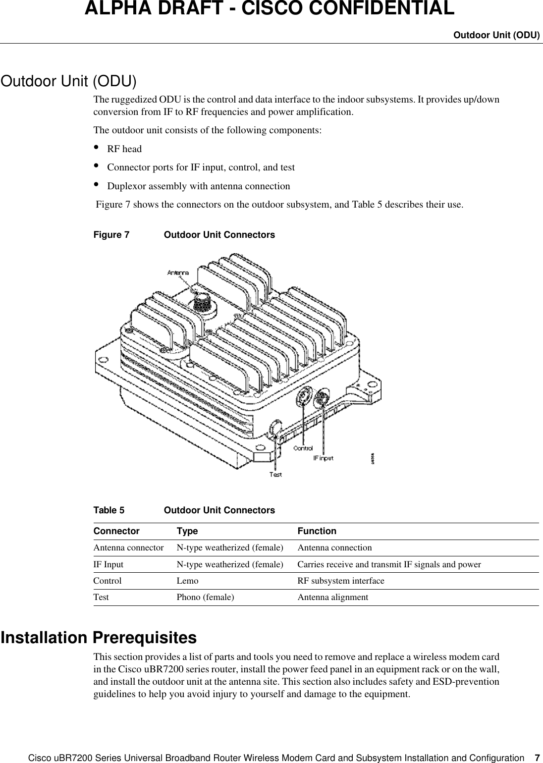
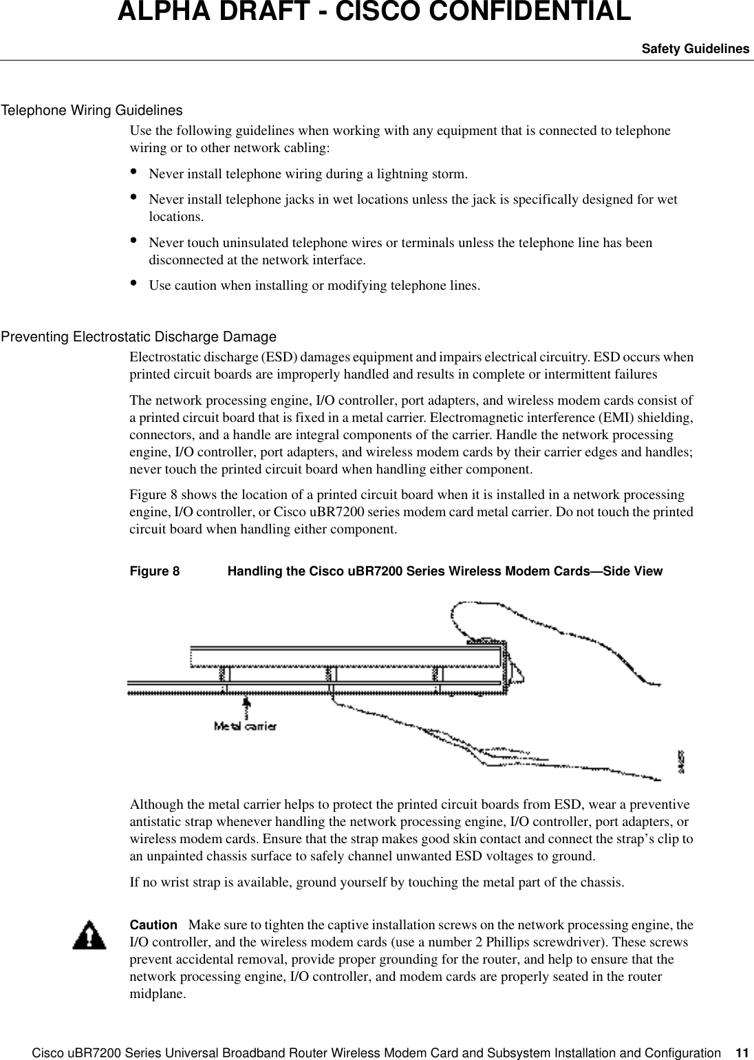
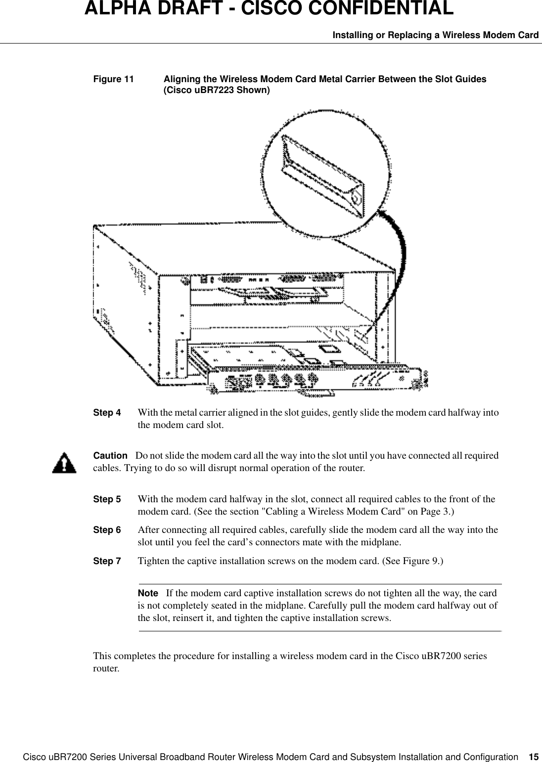
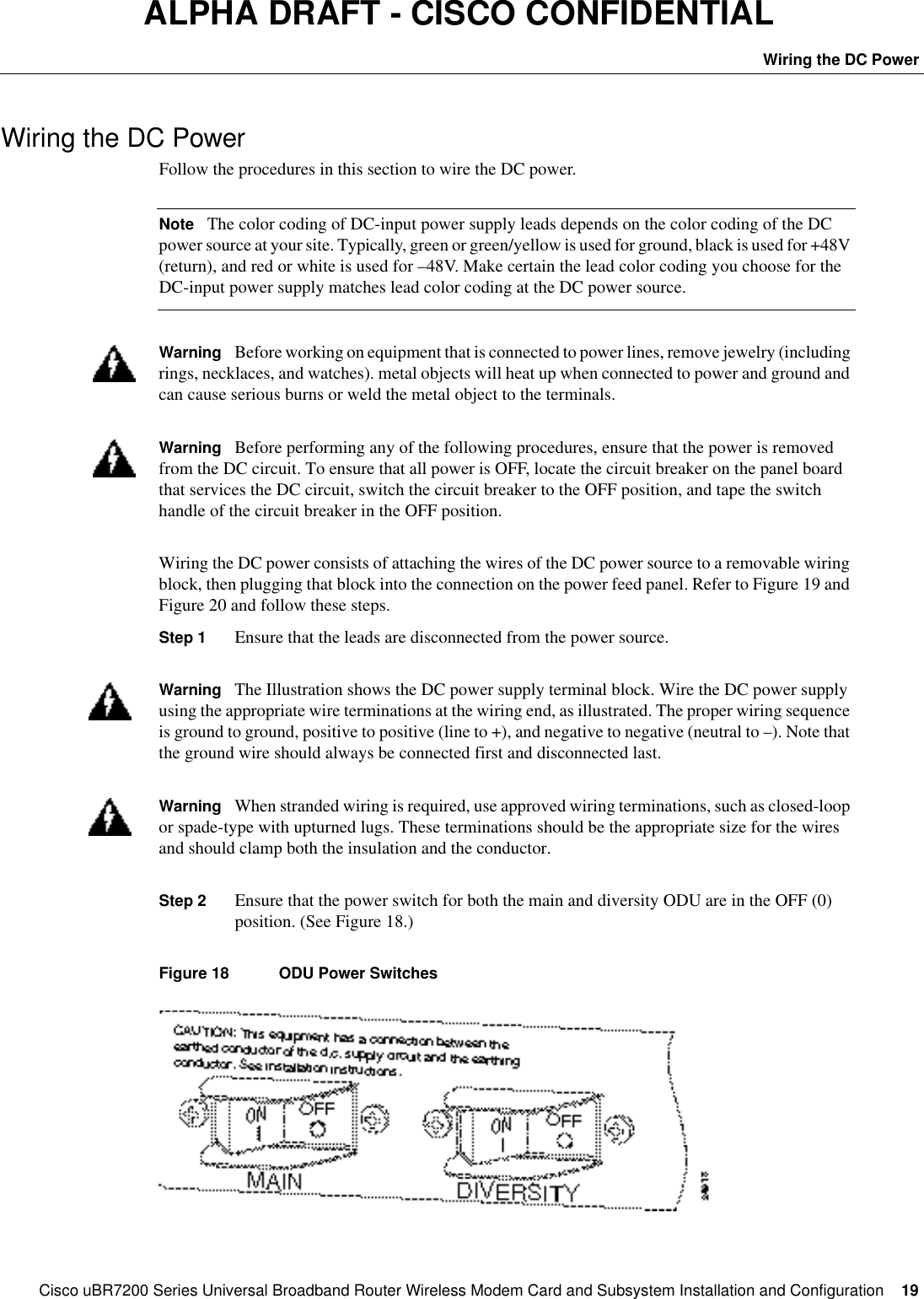
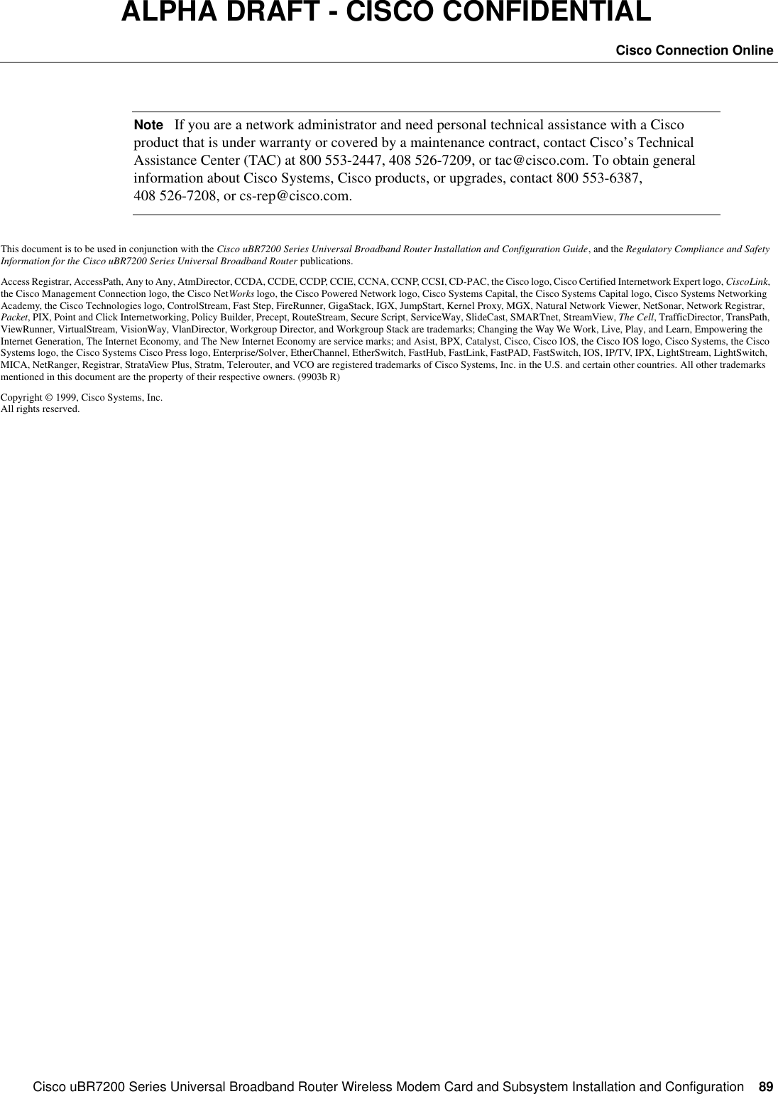
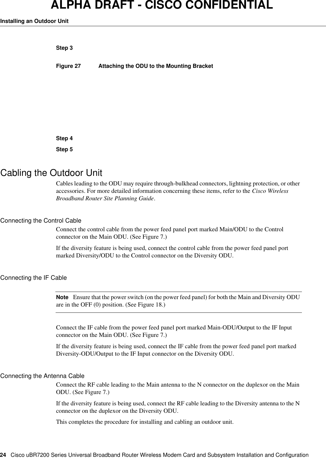
![CiscouBR7200 Series Universal Broadband Router Wireless Modem Card and Subsystem Installation and Configuration 23Mounting the Outdoor UnitALPHA DRAFT - CISCO CONFIDENTIAL[CAUTIONS]Step1Figure24 Attaching the Mounting Bracket to the Antenna PoleStep2Step3Figure25 Attaching the ODU to the Mounting BracketStep4Step5Mounting the Outdoor Unit on a WallUse the following steps to mount the outdoor unit on a wall:[CAUTIONS]Step1Figure26 Attaching the Mounting Bracket to the WallStep2](https://usermanual.wiki/Cisco-Systems/OFDM-MMDS2/User-Guide-38809-Page-23.png)
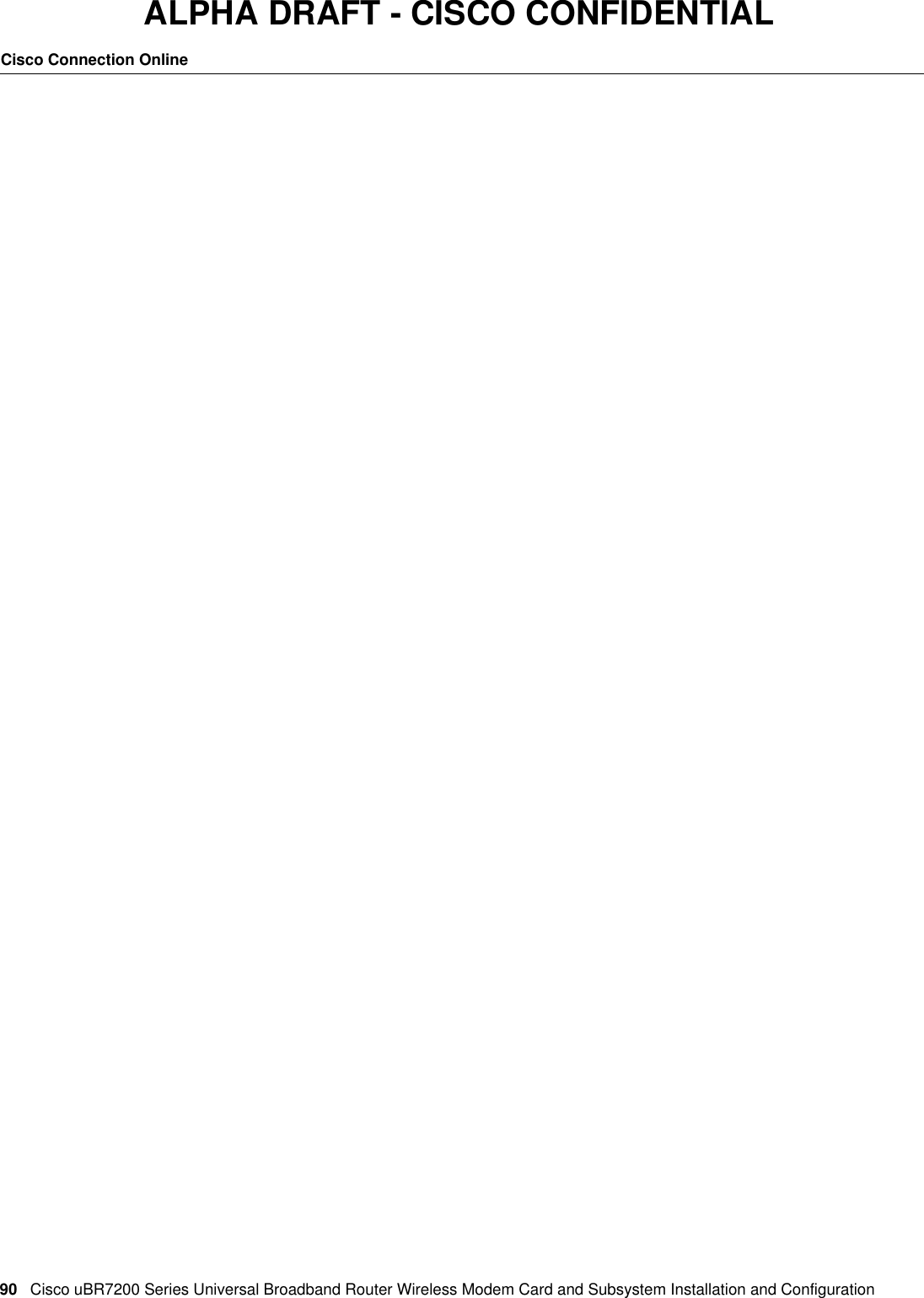
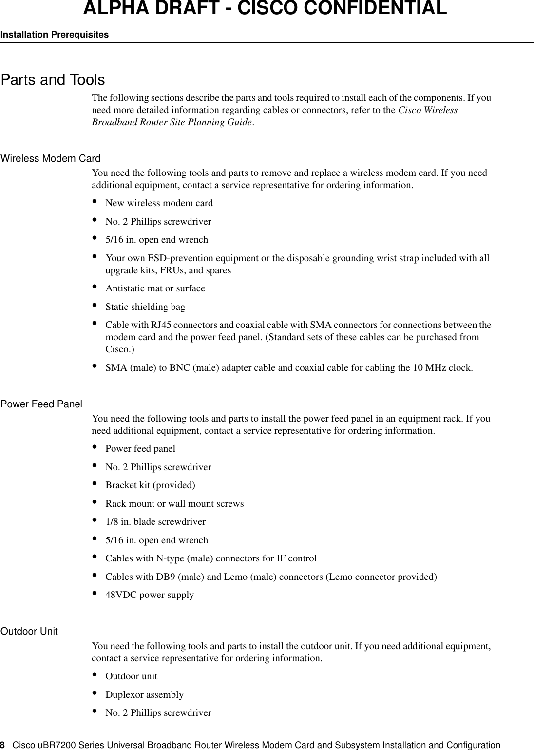
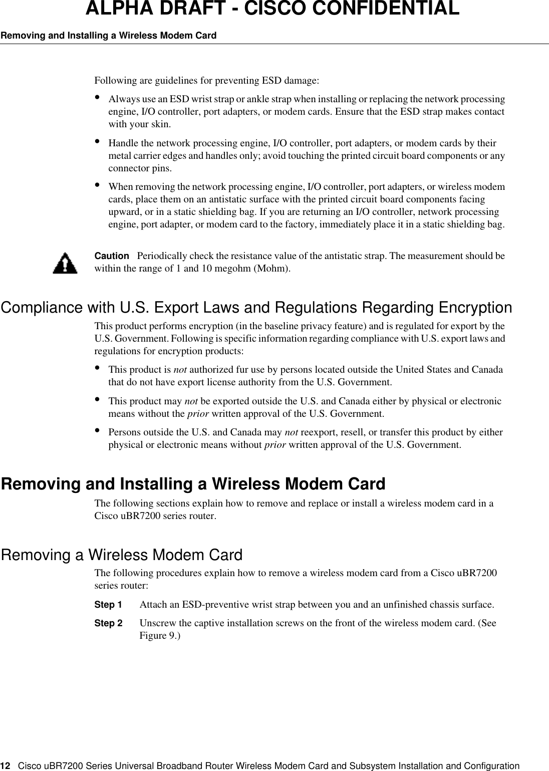
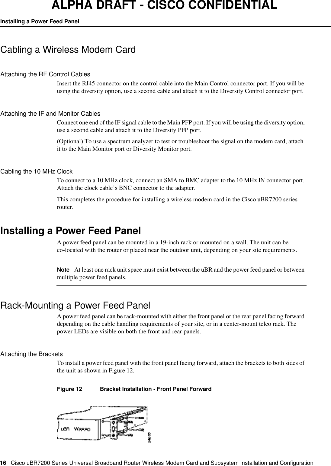
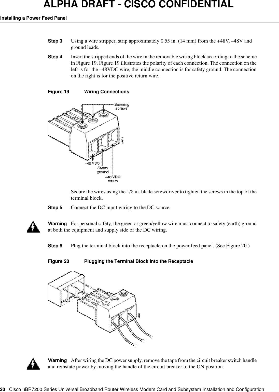
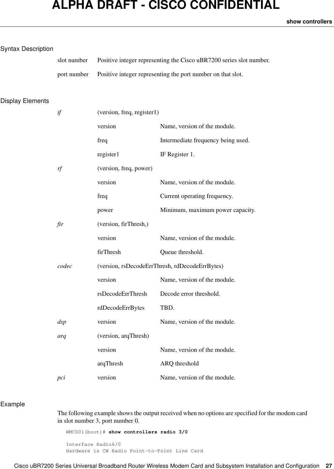
![CiscouBR7200 Series Universal Broadband Router Wireless Modem Card and Subsystem Installation and Configuration 25Configuring a Wireless Modem CardALPHA DRAFT - CISCO CONFIDENTIALConfiguring a Wireless Modem CardAfter you have installed or replaced a wireless modem card, you must use the Cisco IOS software command-line interface (CLI) to configure the modem card for correct operations of the card and wireless subsystems. The commands for login and completing the configuration are described in this section. Commands are also provided to enable you to verify the individual tasks in the configuration process.NoteYou must perform a basic configuration of the CiscouBR7200 series router before configuring the wireless modem cards. refer to the CiscouBR7200 Series Universal Broadband Router Installation and Configuration Guide publication that shipped with your CiscouBR7246 or CiscouBR7223 for more information.Syntax ConventionsThe following conventions are used in the:NoteAll examples in the following sections use the hostname of WMCS01.loginUse the steps in Table6 to login and start the configuration process.NoteSome commands require privileged configuration access privileges. These commands are marked “Privileged configuration access is required”.Convention Meaningcommand-name The actual CLI command<replaceable parameters> A parameter that the user needs to substitute to identify the object of interest.[optional parameter] A parameter that need not be specified. If specified it will qualify the command for the specified subset.keyword A keyword that has significance in the context it is being used.{choice1 | choice2} Represents the set of choices, one of which must be specified(detail1, detail2) Details displayed by the CLI in response to a show command](https://usermanual.wiki/Cisco-Systems/OFDM-MMDS2/User-Guide-38809-Page-25.png)
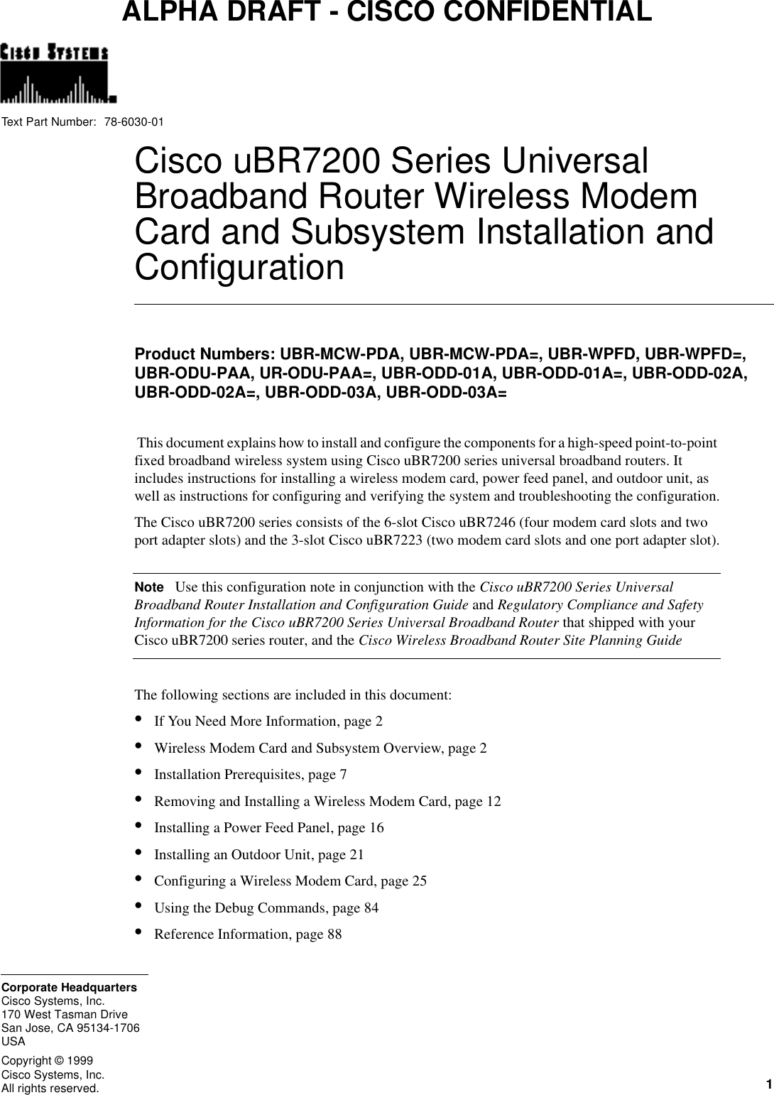
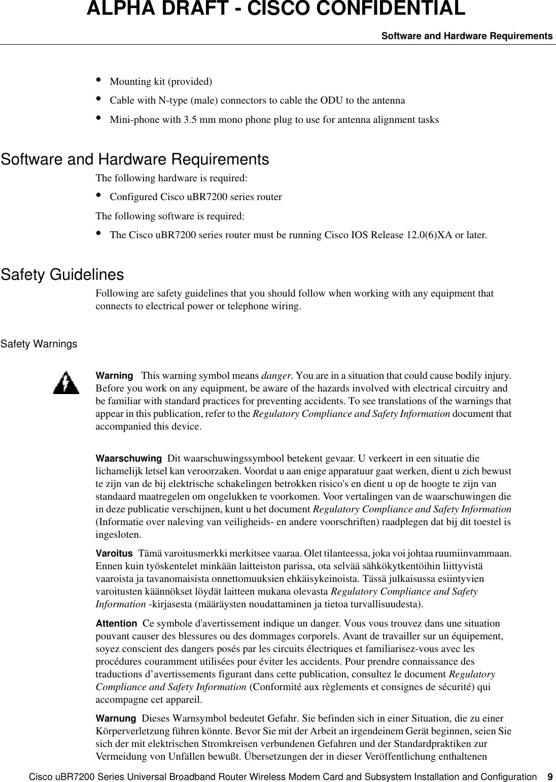
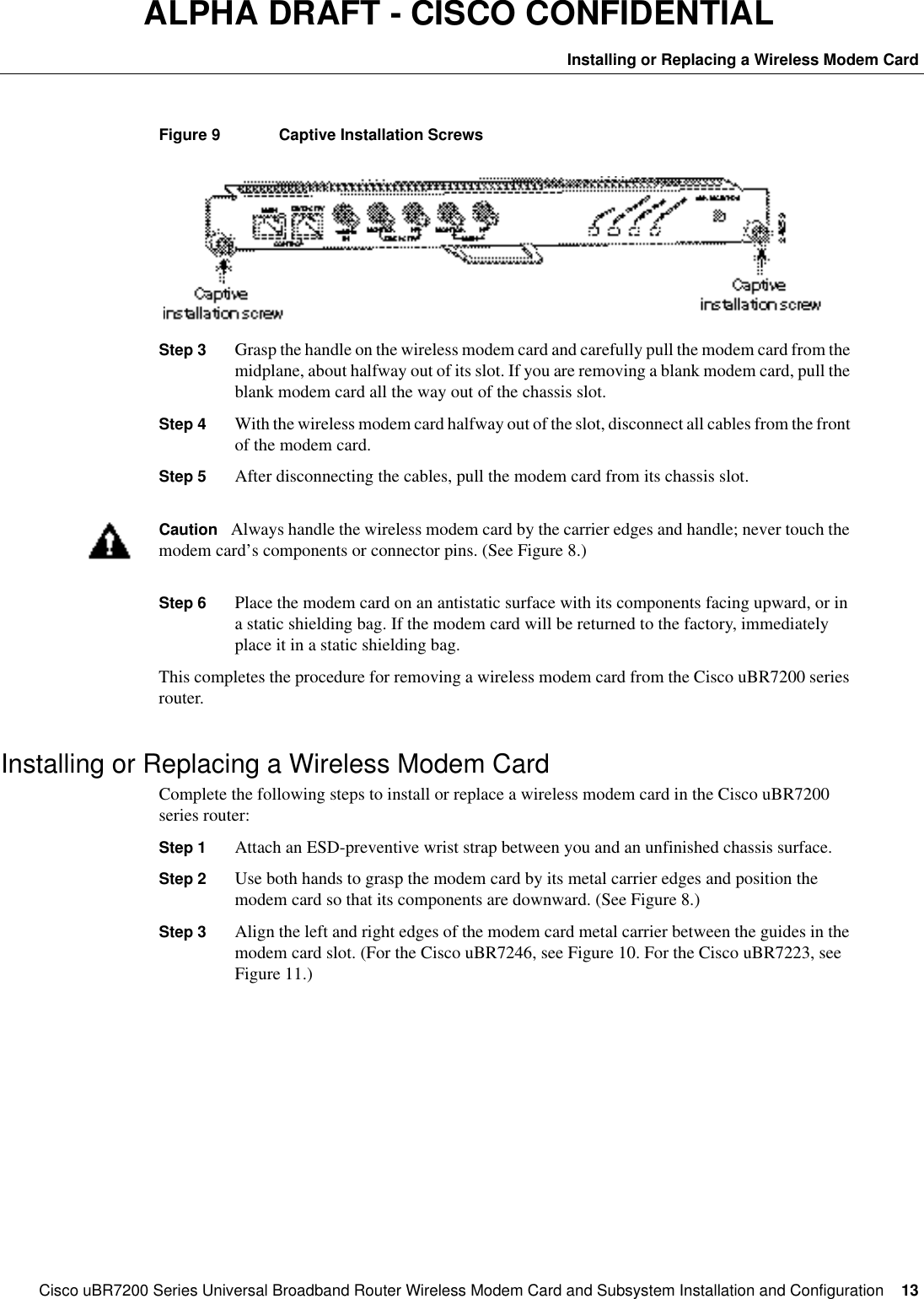
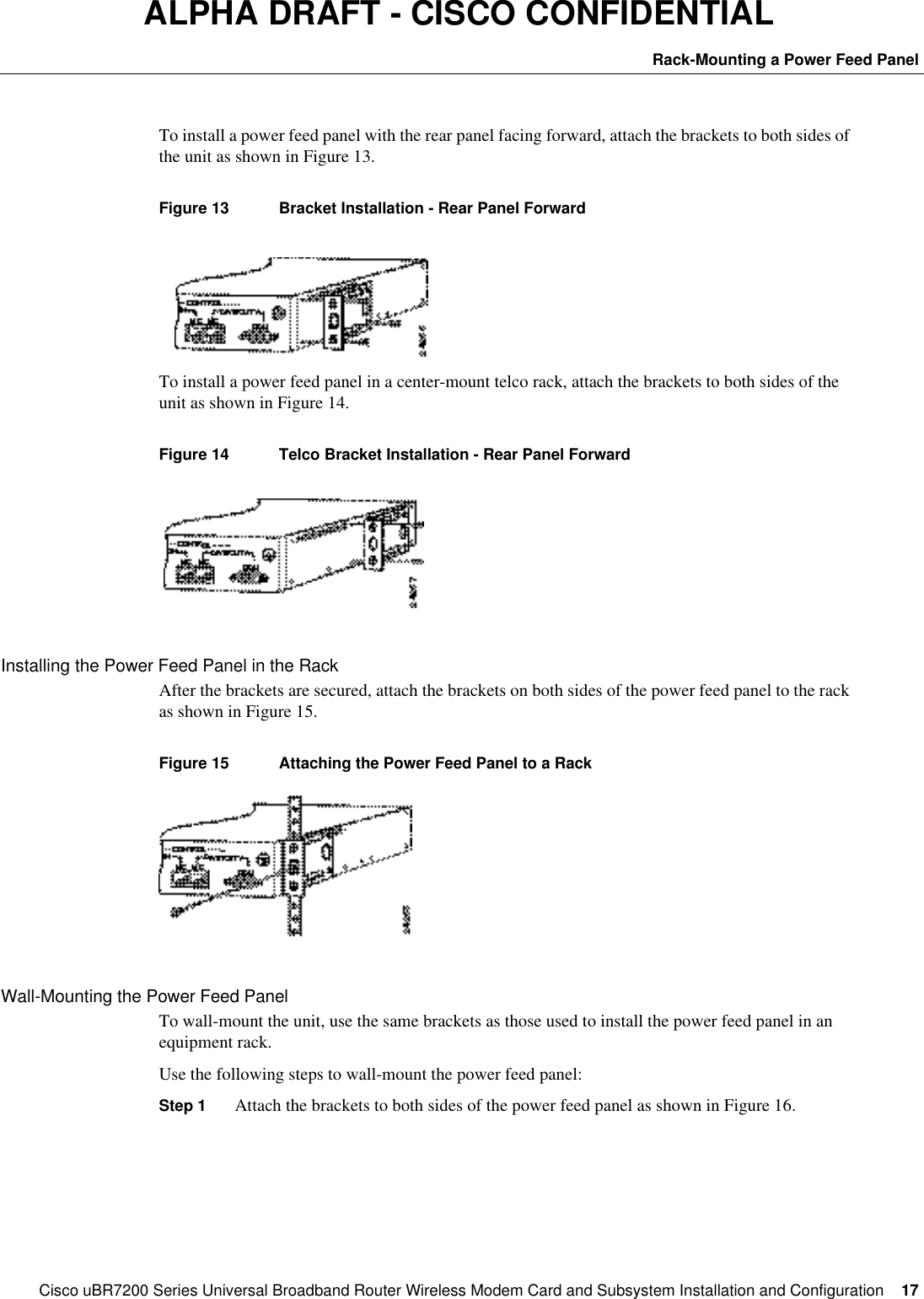
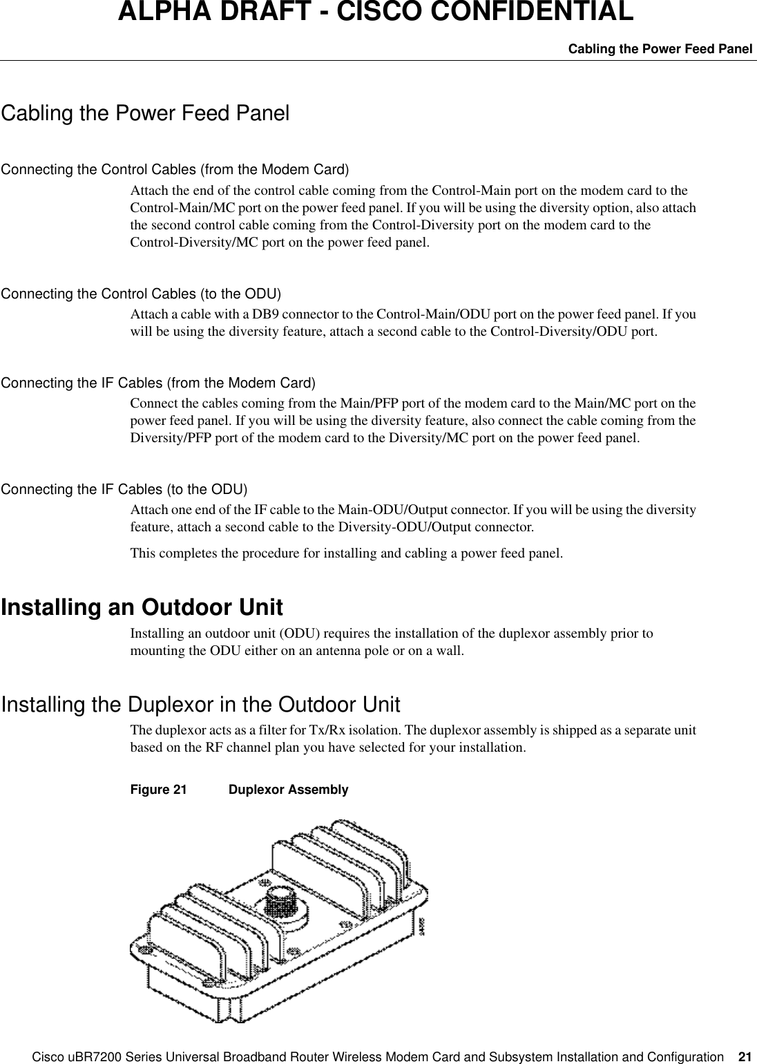
![26CiscouBR7200 Series Universal Broadband Router Wireless Modem Card and Subsystem Installation and ConfigurationConfiguring a Wireless Modem CardALPHA DRAFT - CISCO CONFIDENTIALshow controllersUse this command to display all or a subset of attributes of a particular modem card. If none of the options are specified, all the hardware subsystem(s) information will be displayed. Commonly displayed parameters are shown in the "Display Elements" section. Actual output parameters depend on the hardware and implementation. Privileged configuration access is required.Unless an error occurs, no notifications are displayed on the console. show controllers radio <slot number>/<port number> [{if | rf | fir | codec | dsp | arq | pci | phy | driver}]Table6Login StepsStep Command Purpose 1WMCS01(boot)> enable Password: <password> WMCS01(boot)# Enter Exec mode. Enter the password. You are in Exec mode when the prompt changes to WMCS01(boot)#. 2WMCS01(boot)# configure terminalpassword: <password>WMCS01(boot)(config)# Enter Privileged Configuration mode. Enter the Privileged Configuration password.You are in this mode when the prompt changes to WMCS01(boot)(config)#.3WMCS01(boot)(config)# interface radio 3/0WMCS01(boot)(config-if)#Enter Interface Configuration mode for the specified modem card.You are in this mode when the prompt changes to WMC01(boot)(config-if)#](https://usermanual.wiki/Cisco-Systems/OFDM-MMDS2/User-Guide-38809-Page-26.png)
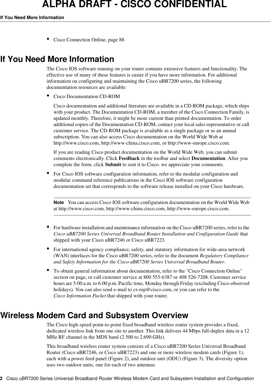
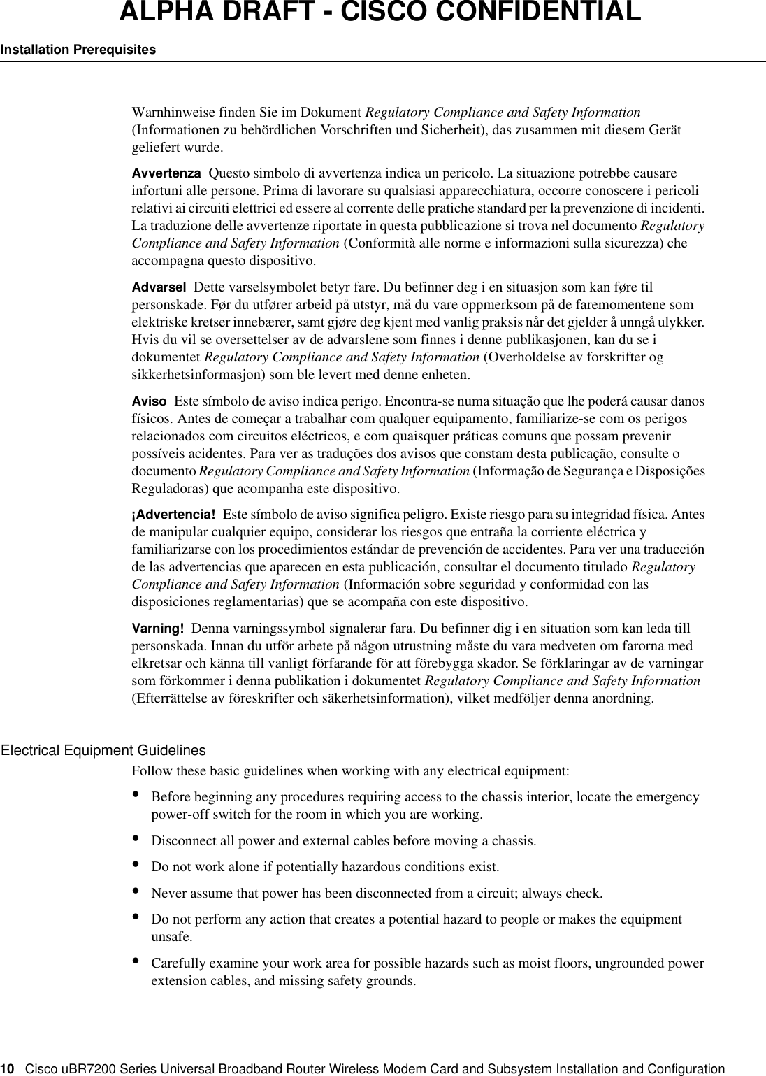
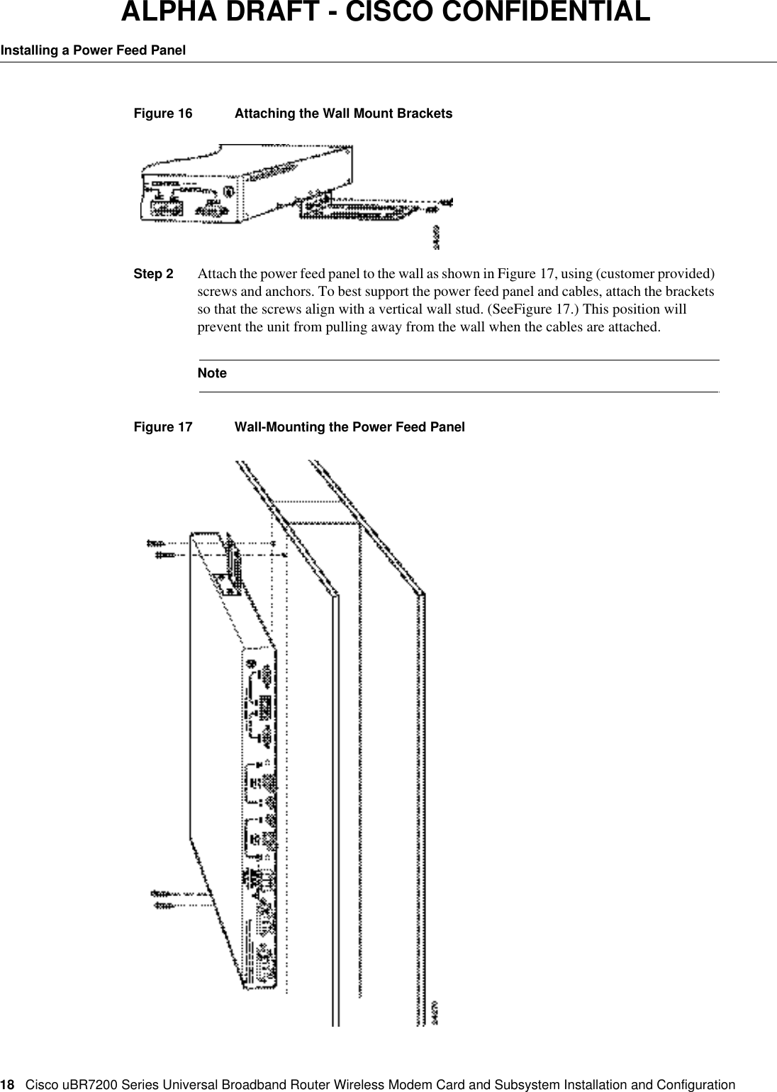
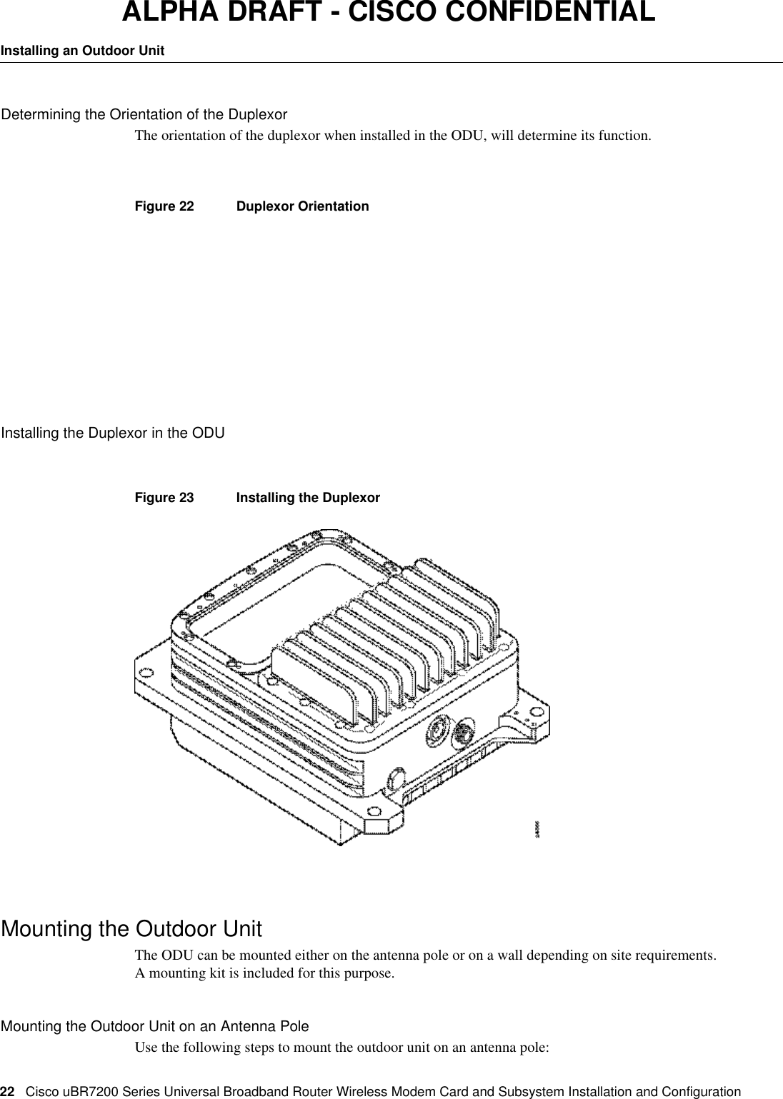
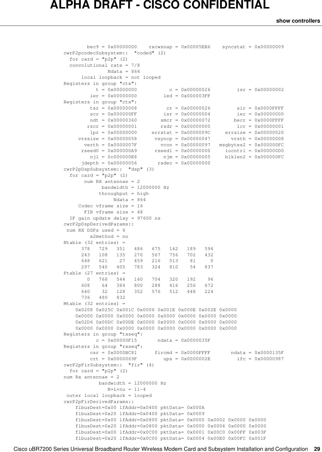
![28CiscouBR7200 Series Universal Broadband Router Wireless Modem Card and Subsystem Installation and ConfigurationConfiguring a Wireless Modem CardALPHA DRAFT - CISCO CONFIDENTIAL throttled 0 enabled 0 disabled 0 Rx: spurious 0 framing_err 0 no_buffer 0, pause_no_err_ints 0 no_enqueue 0 no_stp 0 no_enp 0 Tx: full 0 drop 0 rx ring entries 32 tx ring entries 128 Rx ring 0x4B05A0C0 shadow 0x61399C60 head 2 Normal Latency Tx ring 0x4B05A680 shadow 0x6139A1C0 head 0 tail 0 count 0 Low Latency Tx ring 0x4B05A220 shadow 0x61399D50 head 3 tail 3 count 0PCI Configuration Registers Device/Vendor IDs - 0x00141137 Command/Status - 0x02000086 Latency Timer - 0x0000FF00 Base Address 0 - 0x000001FFPCI Interface FPGA dmac_control - 0x00440002 dmac_status - 0x00004000 dmac_int_status - 0x99800001 dmac_int_enable - 0x66710FF8 dmac_tx0_ring_base - 0x4B05A220 dmac_tx1_ring_base - 0x4B05A680 dmac_rx_ring_base - 0x4B05A0C0 dmac_configuration - 0x66040303 local_bus_error_status - 0x00000000 local_bus_error_address - 0x010C0000 local_bus_reset - 0x00000000 fpga_configuration_control - 0x00000000 fpga_configuration_status - 0x000000FFPHY Interface FPGA tx_cbc_iv[0] - 0x00000000 0x00000000 0x00000000 0x00000000 tx_cbc_iv[1] - 0x00000000 0x00000000 0x00000000 0x00000000 rx_cbc_iv[0] - 0x00000000 0x00000000 0x00000000 0x00000000 rx_cbc_iv[1] - 0x00000000 0x00000000 0x00000000 0x00000000 rx_key_sequence[0] - 0x00000000 rx_key_sequence[1] - 0x00000000 framer_control - 0x00000003 overrun_count - 0x00000000 loopback_control - 0x00000000 timer_control - 0x00000000 timer_down_count - 0x00000001cwrP2pArqSubsystem:: "arq" (1) for card = "p2p" (2) burst rate = 10869 bursts/sec codeword rate = 24358 codewords/sec ARQ overhead = 7 codewords processing latency = 1400 usec (34 codewords) overall latency = 20000 usec (453 codewords) ARQ burst size = 16 codewords ARQs per CW error = 4 ARQ spacing = 64 codewords RRs per SCW error = 6 RR spacing = 38 codewordsRegisters in group "arq": mi = 0x00005EB5 rrc = 0x000001FC arqc = 0x000001FB atxi = 0x000003D0 arxi = 0x000003A0 arqo = 0x00000007 burst = 0x00000010 cwthsh = 0x00002F5A prbs = 0x00000000 dlat = 0x000000FF intstat = 0x000007D4 inten = 0x00000000 host = 0x00000001 arqm = 0x00000035 vlat = 0x0000007F cwlen = 0x00000080 hdlc = 0x00000000 rxlen = 0x000000F3cwespc = 0x000003FF besize = 0x00000007 bespc = 0x0000FFFF cwbe = 0x00000000 test = 0x00000000 cwerr = 0x00000000 ccwerr = 0x00000000 derr = 0x00000047 sberr = 0x00000000 arqreq = 0x00000000 plarq = 0x00000000 plrrr = 0x00000000 plrr = 0x00000000 bec1 = 0x00000000 bec2 = 0x00000000 bec3 = 0x00000000 bec4 = 0x00000000 bec5 = 0x00000000 bec6 = 0x00000000 bec7 = 0x00000000 bec8 = 0x00000000](https://usermanual.wiki/Cisco-Systems/OFDM-MMDS2/User-Guide-38809-Page-28.png)
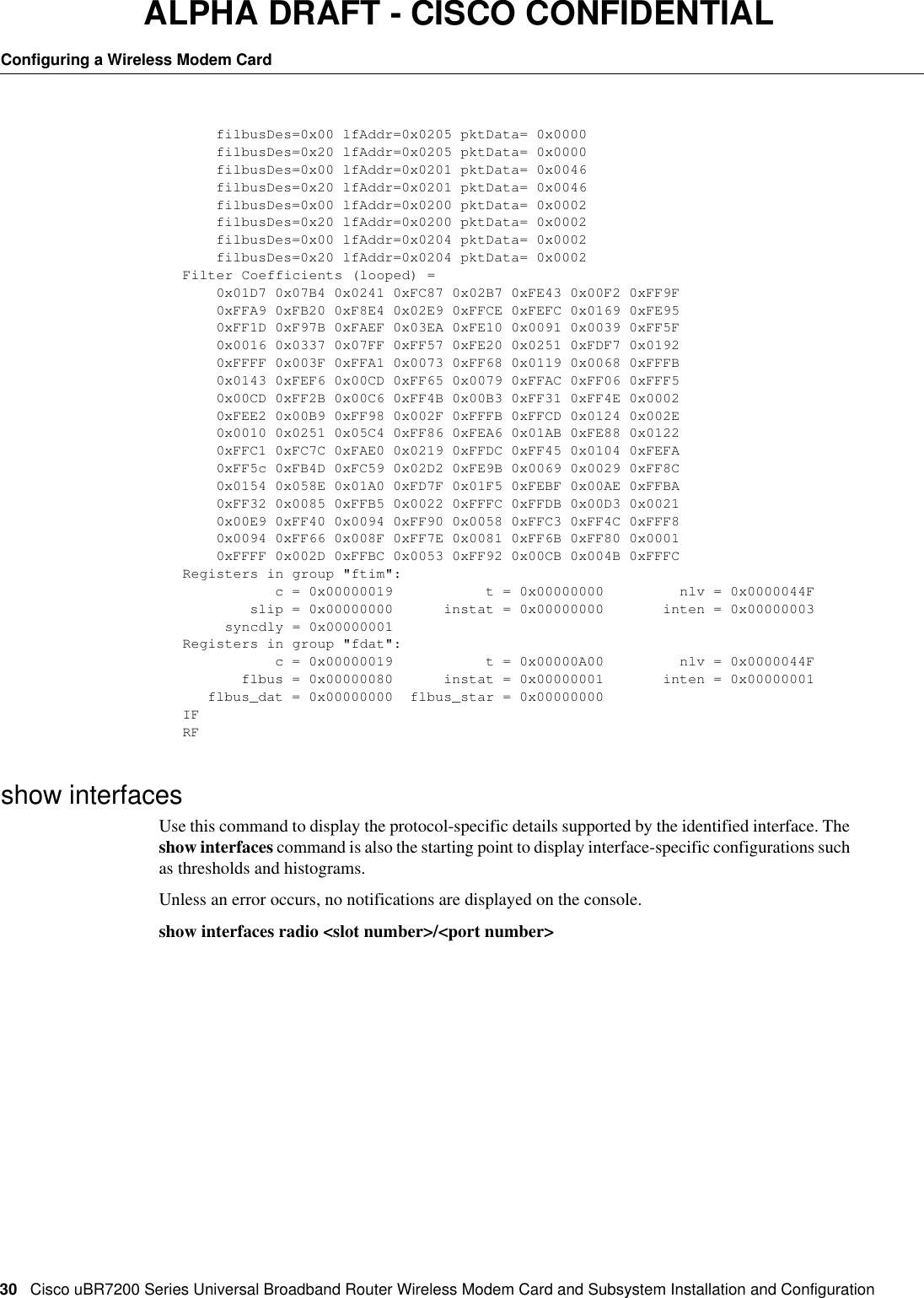
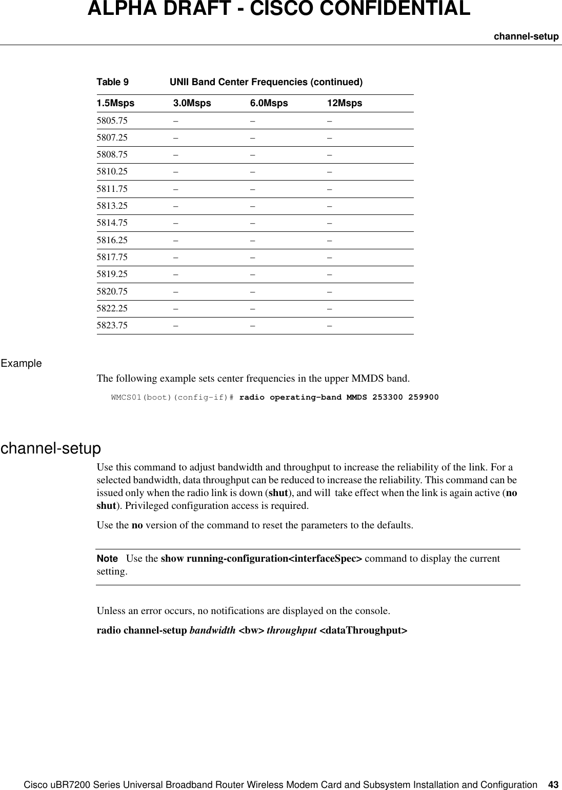
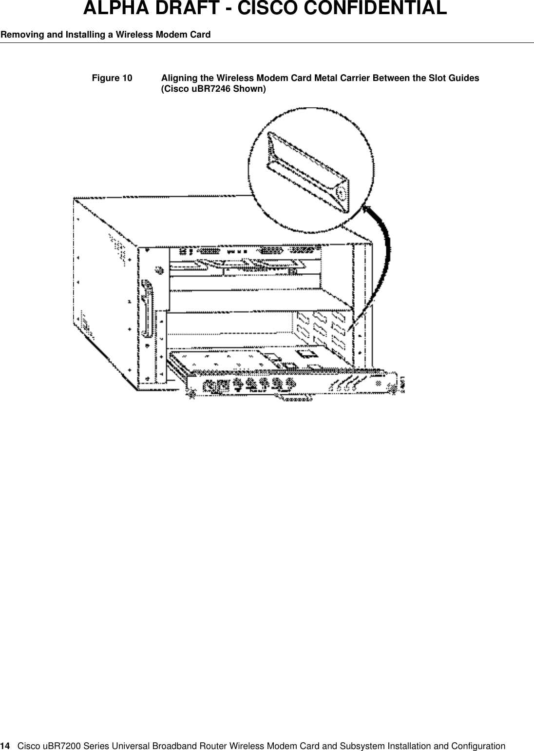
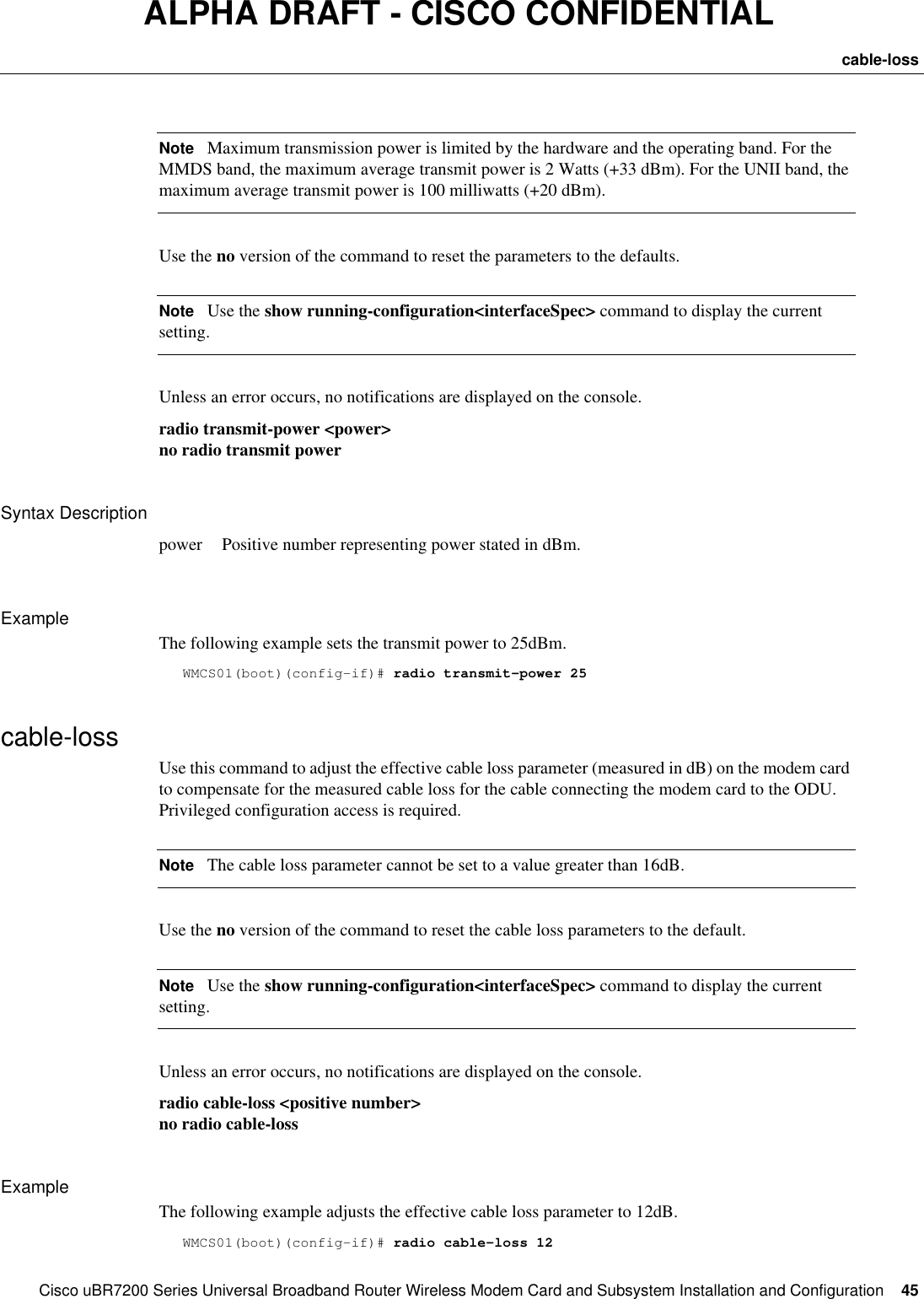
![44CiscouBR7200 Series Universal Broadband Router Wireless Modem Card and Subsystem Installation and ConfigurationConfiguring a Wireless Modem CardALPHA DRAFT - CISCO CONFIDENTIALSyntax DescriptionExampleThe following example configures a 6MHz bandwidth and high throughput.WMCS01(boot)(config-if)# radio channel-setup bw 6 throughput highself-testUse this command to configure the card to download and execute self-tests. Use the [enable] option to execute self-tests each time the card is initiated (no shut). Use the command without the [enable] option to perform a self-test only on the first no shut after initiation. Privileged configuration access is required.Use the no version of the command to configure a restart of the link without executing self-tests. NoteUse the show running-configuration<interfaceSpec> command to display the current setting. Unless an error occurs, no notifications are displayed on the console. radio self-test [enable]no radio self-testExampleThe following example shows the configuration command to download and execute self-tests each time the modem card is enabled.WMCS01(boot)(config-if)# radio self-test enabletransmit-powerUse this command to configure the antenna to transmit the specified amount of power (specified in dBm) when in operation. Privileged configuration access is required.bw {1.5 | 3 | 6 | 12}NoteThe 1.5MHz and 3MHz bandwidths are for future use.dataThroughput {high | medium | low} high (default) At 12 MHz, maximum 44.4 Mbps.At 6 MHz, maximum 22.2 Mbps.medium At 12 MHz, maximum 39.1 Mbps.At 6 Mhz, maximum 19.6 Mbps.low At 12 MHz, maximum 22.4 Mbps.At 6 Mhz, maximum 11.2 Mbps.](https://usermanual.wiki/Cisco-Systems/OFDM-MMDS2/User-Guide-38809-Page-44.png)
![46CiscouBR7200 Series Universal Broadband Router Wireless Modem Card and Subsystem Installation and ConfigurationConfiguring a Wireless Modem CardALPHA DRAFT - CISCO CONFIDENTIALshow imagehdrUse this command to display details of the images to be downloaded on a single chip or on all chips.If a particular chip is identified, the details of the image to be loaded on that chip are displayed. If no chip name is specified, the current radio configuration is retrieved for every chip on the modem card. All the images in the repository are compared. The image that provides the closest match in capability is selected, and the details of that image are displayed. Unless an error occurs, no notifications are displayed on the console. Name [{ current | operational }]]Syntax DescriptionExampleThe following example will display the image details of the chip named dspla currently loaded on the chip on the modem card in slot 3, port 0.WMCS01(boot)(config-if)(offline)# show interface radio 3/0 imagehdr dspla currentshow radio repositoryUse this command to display the protocol-specific list of images in the repository. The repository is a list of current configuration images. When the modem card is initiated (no shut), this list is searched and the correct image downloaded. Privileged configuration access is required.Unless an error occurs, no notifications are displayed on the console. show radio repository [header] [protocol]Syntax DescriptionExampleThe following example lists images related to memory.WMCS01(boot)(config-if)# show radio repository memmem:/ClarityImages/dsp1Dual.imgmem:/ClarityImages/dsp2Dual.imgmem:/ClarityImages/dsp1Single.imgchipName A character string identifying a chip.current Display the image header (details) for the image currently loaded on the chip.operational Display the image header for the image that will be loaded on the chip for the current configuration.header Image header details associated with the list of images will also be displayed.protocol <{mem | tftp | flash}>](https://usermanual.wiki/Cisco-Systems/OFDM-MMDS2/User-Guide-38809-Page-46.png)
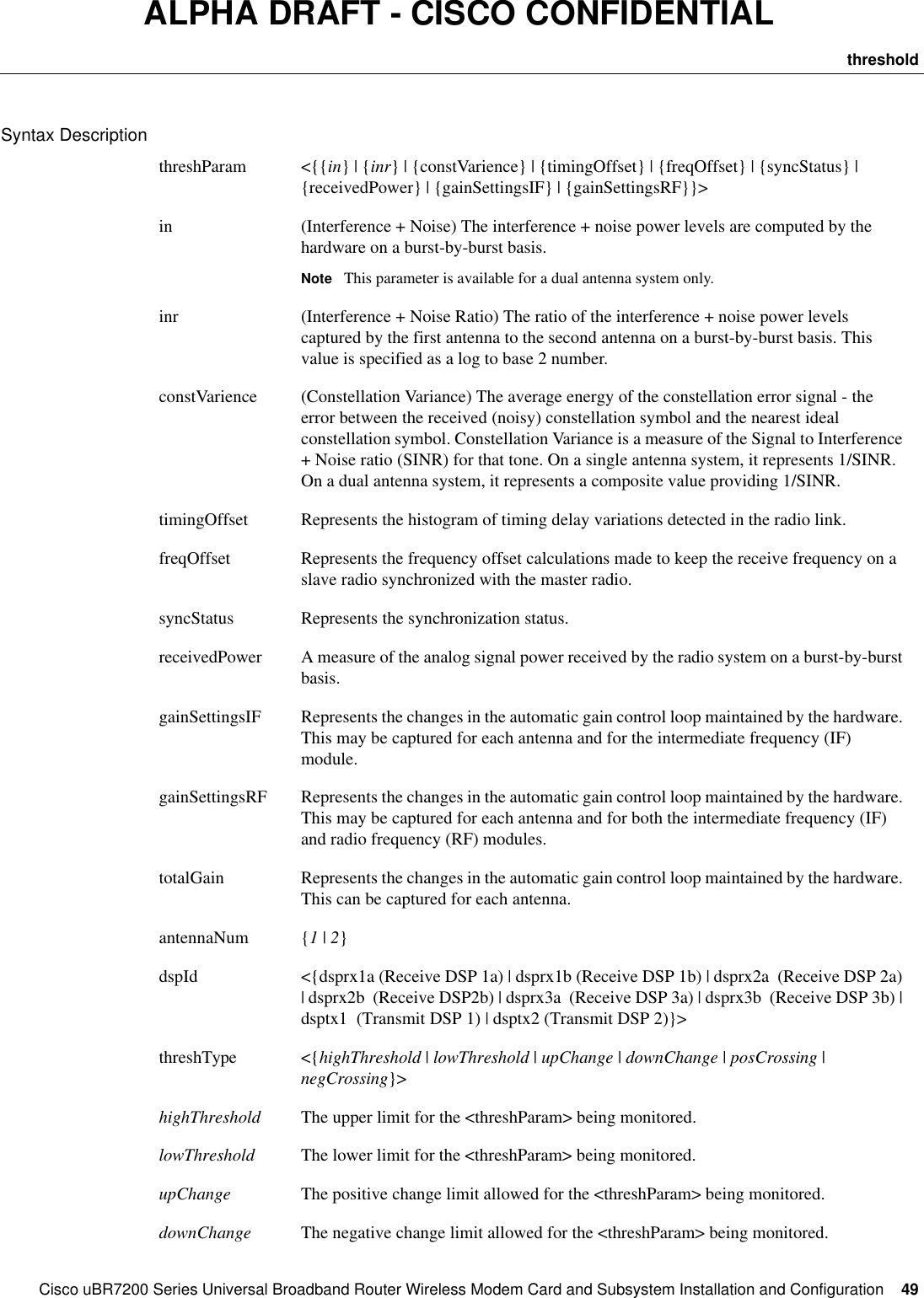
![48CiscouBR7200 Series Universal Broadband Router Wireless Modem Card and Subsystem Installation and ConfigurationConfiguring a Wireless Modem CardALPHA DRAFT - CISCO CONFIDENTIALSyntax DescriptionExampleThe following example selects the image dspla.img at the address 200.33.33.44 to be moved to the start of the repository list.WMCS01(boot)(config-if)# radio image-move tftp://200.33.33.44/myDspImages/dspla.imgthresholdUse this command to configure a threshold event specification. When the specified threshold is crossed, an event of type <threshParam> will be generated and the event logged to the console. Privileged configuration access is required.Every event is propagated to the SNMP agent by default. Only one threshold may be defined for each of the identified <threshParam> <threshType> <dspId> combination. When a threshold is crossed, the <threshParam> <threshType> <dspId> combination identifies the threshold specification that caused the event.For every threshold defined, antennaNum is conditional. Antenna number is applicable for the threshParam attributes in, receivedPower, gainSettingsIf, gainSettingsRF, and totalGain.NoteIf an antenna number is used when a threshold is created, it must also be specified when it is deleted.Use the no version of the command to terminate the event-threshold setup. The no radio threshold command requires the threshParam, threshType, and dspId attributes.For each event, the <threshParam> <dspID><threshType><eventType> will be output identifying the threshold crossed.radio threshold <threshParam> <antennaNum> [dsp <dspId>] <threshType> <threshValue> <repeatTime> <clearTime>no radio threshold <threshParam> <antennaNum> [dsp <dspId>] <threshType>image <protocol>://<host>/<directory>/<filename>protocol <{mem | tftp | flash}>host IP Address.directory Directory name. No embedded spaces accepted.filename Name of image file.](https://usermanual.wiki/Cisco-Systems/OFDM-MMDS2/User-Guide-38809-Page-48.png)
![50CiscouBR7200 Series Universal Broadband Router Wireless Modem Card and Subsystem Installation and ConfigurationConfiguring a Wireless Modem CardALPHA DRAFT - CISCO CONFIDENTIALDisplay ElementsExampleThe following command sequence will set up a threshold for totalGain. When the totalGain for the system on antenna2 falls below 70, the eventSet event type will be generated.WMCS01(boot)(config-if)# radio threshold totalGain 2 dsp dsprx1a lowThreshold 70show interfaces (thresholds)Use this command to display the display the set of currently configured thresholds on the modem card on the specified DSP. If dspNum is not specified, the thresholds for DSP 3 will be displayed.Unless an error occurs, no notifications are displayed on the console. show interfaces radio <slot/port> thresholds [dspNum]posCrossing The limit that the <threshParam> should cross when it is increasing in value.negCrossing The limit that the <threshParam> should cross when it is decreasing in value.threshValue A 32-bit integral valuerepeatTime When radio signals are monitored, they can oscillate across a specified threshold (such as highThreshold) very rapidly. In such a case, an event is generated for each crossing of the threshold, which could flood the system. The repeatTime parameter specifies the amount of time (in seconds) the system should wait, in this case, before another event of the same type is generated.clearTime When radio signals oscillate across a threshold, it is often desirable to identify when the signal has stabilized. The clearTime parameter specifies how many seconds the radio signal must stay below a threshold (after crossing it once) before the system generates the clear event.eventType {eventSet | eventRepeat | eventClear}eventSet TBDeventRepeat TBDeventClear TBD](https://usermanual.wiki/Cisco-Systems/OFDM-MMDS2/User-Guide-38809-Page-50.png)
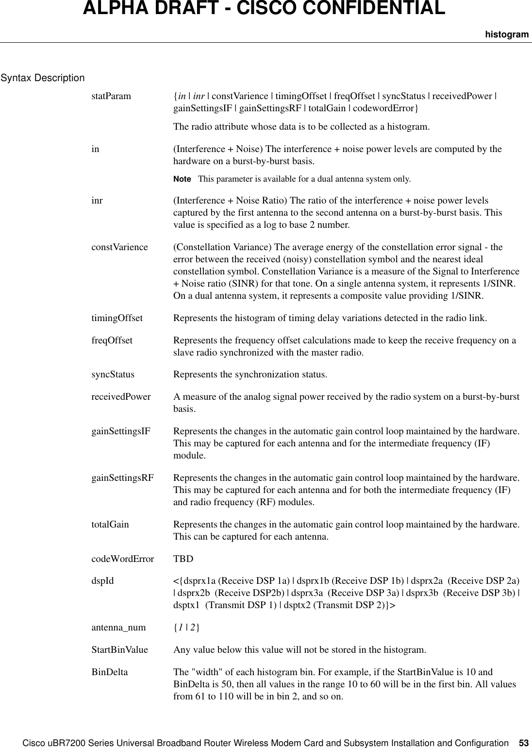
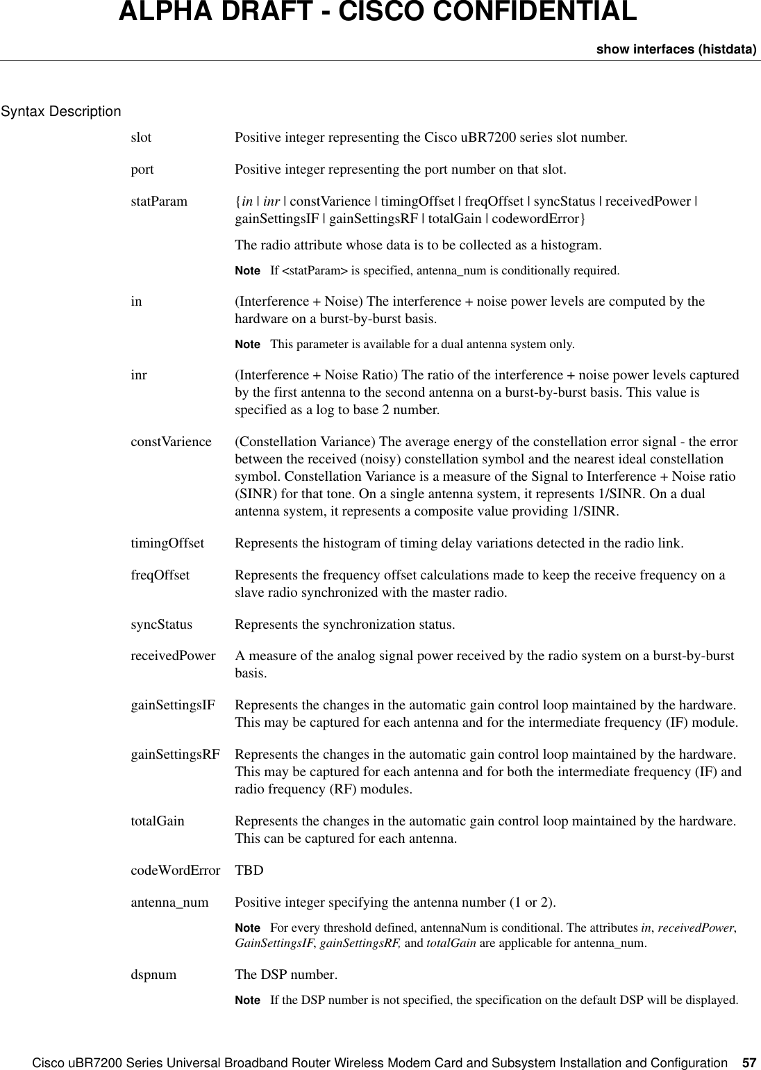
![CiscouBR7200 Series Universal Broadband Router Wireless Modem Card and Subsystem Installation and Configuration 51histogramALPHA DRAFT - CISCO CONFIDENTIALSyntax DescriptionExampleThe following command will display the set of currently configured thresholds for the modem card in slot 3, port 0 on DSP number 5.WMCS01(boot)(config-if)# show interfaces radio 3/0 thresholds dsp 5Threshold AttributefreqOffsetThreshold TypedownChangeAntenna Id2Threshold Value-100Threshold Hysteresis Time0Threshold Limit Time0Threshold Statusnot in servicehistogramA histogram statistic is one where data is sampled every burst and the values are assigned to a fixed number of bins. Assigning a value to a bin simply increments the count for that bin. The number of bins in the histogram is specified by the NumBins parameter.This command configures a histogram collection specification with the software. The data for the histogram is collected as soon as the command succeeds and continues until the specification is deleted using the [no] option or the collectionInterval expires. The data collected is printed out to the console at user-specified intervals. Privileged configuration access is required.For every threshold defined, antennaNum and tone are conditional. The attributes in, receivedPower, GainSettingsIF, gainSettingsRF, and totalGain are applicable for antenna_num. The attributes in, inr, and constVarience are applicable for tone.Use the no version of this command to delete any histogram configuration specification.Use the histdisplay format of this command control the printing of the information to the screen.Use the histclear format of this command to clear the collected histogram data.Unless an error occurs, no notifications are displayed on the console. radio histogram <statParam> [dsp <dspId>] <antenna_num> <StartBinValue> <BinDelta> <NumBins> <BitShift> <BurstTone> [collectionInterval <interval>] [periodic <interval> sum <{true | false}] [tone <circulate | average | number <tone-number> ]no radio histogram <statParam> <antenna_num> [dsp <dspId>]radio histdisplay <statParam> <antenna_num> [dsp <dspId>] {on | off}radio interface <slot>/<port> histclear <statParam> <antenna_num> [dsp <dspId>]slot Positive integer representing the CiscouBR7200 series slot number.port Positive integer representing the port number on that slot.dspNum The DSP number.](https://usermanual.wiki/Cisco-Systems/OFDM-MMDS2/User-Guide-38809-Page-51.png)
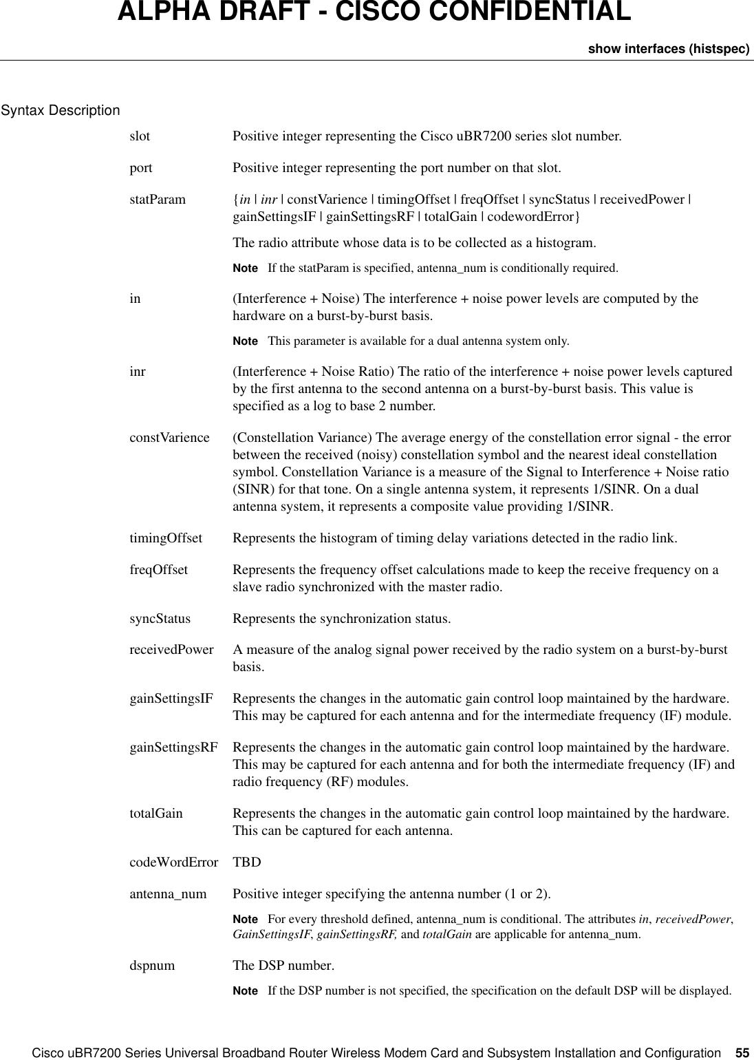
![54CiscouBR7200 Series Universal Broadband Router Wireless Modem Card and Subsystem Installation and ConfigurationConfiguring a Wireless Modem CardALPHA DRAFT - CISCO CONFIDENTIALExampleThe following example will configure a histogram specification. The histogram collection will start as soon as the command succeeds. It will collect a histogram for interference noise ratio. The histogram will be collected on dsprx2a with starting bin of 2^-4 (a starting ratio of 0.0625), bindelta of 1 and 32 bins in total, and no bitshift. It will cycle through the frequency tones for every successive sample. The collection will continue for 1 hour, reporting data every 30 seconds and keeping the cumulative histogram.WMCS01(boot)(config-if)# radio histogram inr dsp dsprx2a -4 1 32 0 collectionInterval 3600 circulate periodic 30 sum trueshow interfaces (histspec)Use this command to display the details of the histogram specifications currently configured. If none of the optional parameters are specified then all histogram specifications on the modem card are displayed.Unless an error occurs, no notifications are displayed on the console. show interfaces radio <slot/port> histspec [<statparam> <antenna_num> [dsp <dspnum>]]NumBins The number of histogram bins to be configured for the collection.BitShift Specifies the number of bits by which the collected data should be shifted to the right, providing a mechanism to control overflow of the values in the histogram.collectionInterval Specifies, in seconds, the interval in which histogram data will be collected.periodic Specifies, in seconds, how often the collected histogram data should be printed to the screen. The sum option specifies whether successive histogram sets retrieved from the hardware should be added to replace the existing histogram data.Specifying a statistic collection to be periodic effectively reduces the size of the NumBins to half the possible amounts. The default is periodic. If the interval is 0, output is generated only at the termination of the collection.tone Identifies how the histogram sample should be computed when sampling a burst. A burst contains data samples from N frequency tones.circulate Implies successive histogram data samples should use successive frequency tones.average Implies successive histogram samples should average the burst data over all the frequencies and use that value.number Specifies that a particular tone in the burst should be used to report the histogram data. The frequency tone is passed in as a number specified in the <tone-number parameter.](https://usermanual.wiki/Cisco-Systems/OFDM-MMDS2/User-Guide-38809-Page-54.png)
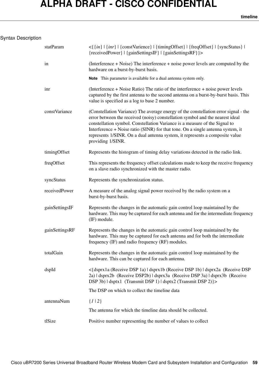
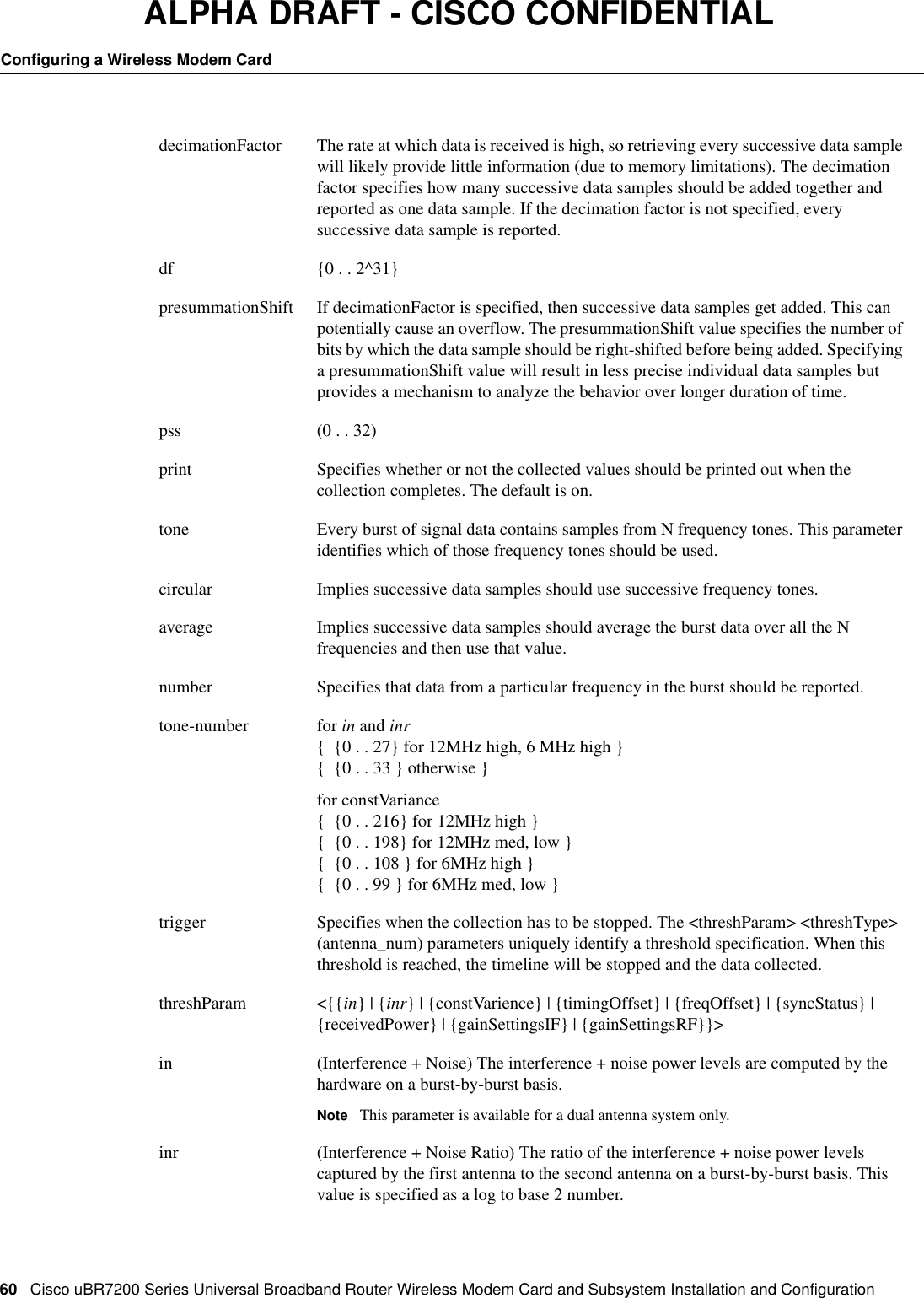
![58CiscouBR7200 Series Universal Broadband Router Wireless Modem Card and Subsystem Installation and ConfigurationConfiguring a Wireless Modem CardALPHA DRAFT - CISCO CONFIDENTIALExampleThe following example shows the command to display the histogram data for the histogram configured on the modem card in slot 3, port 0 of the uBR for DSP 3.WMCS01(boot)(config-if)# show interfaces radio 3/0 histdata inr dsp 3 Histogram 4/1/8 [*=100 ] min=-2 avg=0157 0=<0 **137 0=<1 **115 1=<2 **44 2=<MAX *timelineA timeline is a sequence of data values collected for the specified attribute. The amount of data collected is controlled by the tlSize parameter. The maximum size is determined by the amount of memory the hardware has.Use this command to configure a timeline collection specification with the software. The collection starts as soon as the command succeeds, and continues until the trigger occurs or the timelineStop command is executed. Privileged configuration access is required.For every timeline defined, antenna_num and tone are conditional. The attributes in, receivedPower, GainSettingsIF, gainSettingsRF, and totalGain are applicable for antenna_num. The attributes in, inr, and constVarience are applicable for tone.Use the no version of this command to delete a timeline specification.Use the timelineStop form of the command to stop a currently executing timeline specification.Use the timelineStart form of the command to start a stopped timeline specification.Unless an error occurs, no notifications are displayed on the console. radio timeline <statParam> [dsp <dspId>] <antenna_num> <tlSize> [decimationFactor <df]] [presummationShift <pss>] [print <{on | off}] [tone <circular | average | number <tone-number>] [trigger <threshParams> <threshType> (antenna_num) <postTrigBufMgt>]no radio timeline <statParam> <antenna_num> [dsp <dspnum>]radio interface radio <slot>/<port> timelineStart <statParam> (antenna_num) [dsp <dspnum>]radio interface radio <slot>/<port> timelineStop <statParam> (antenna_num) [dsp <dspnum>]NoteUp to 1024 32-bit words are available for all timeline and histogram parameters on a single DSP. Each histogram requires (NumBins + 4) *2 words; each timeline requires (tlSize + 1) * 2 words. The attributes in in, inr, and constVarience can be captured on any DSP, while the others can be captured only on certain DSPs. Distributing histogram requests across DSPs provided better memory utilization.](https://usermanual.wiki/Cisco-Systems/OFDM-MMDS2/User-Guide-38809-Page-58.png)
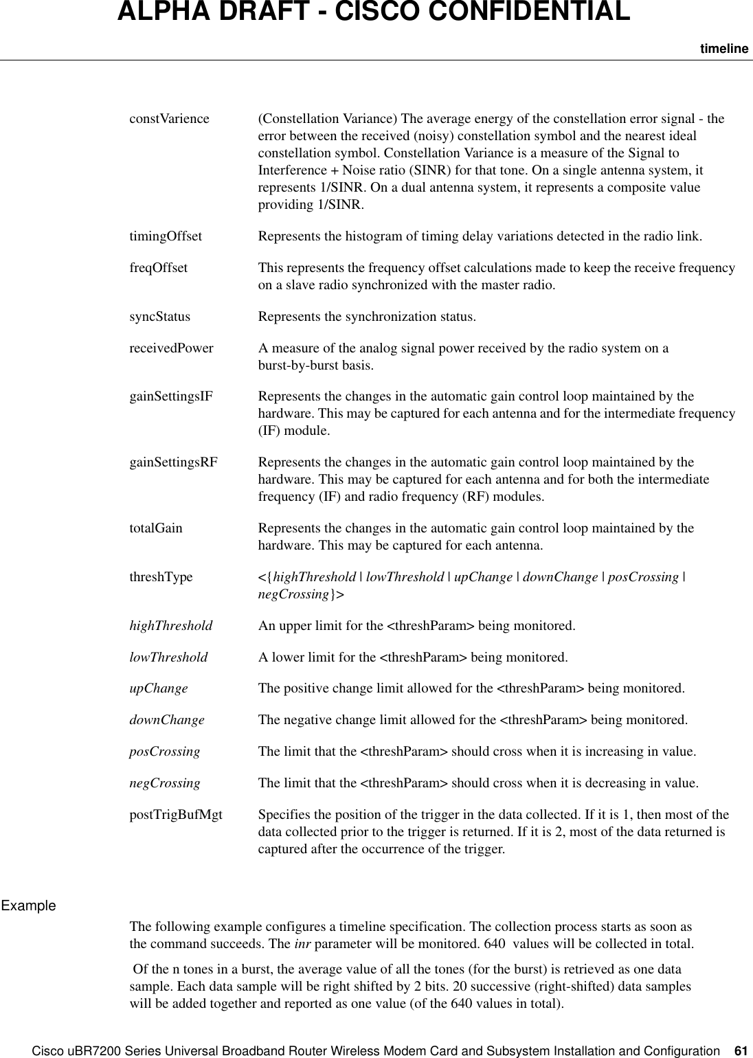
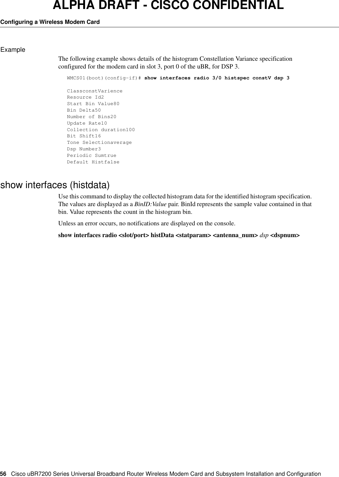
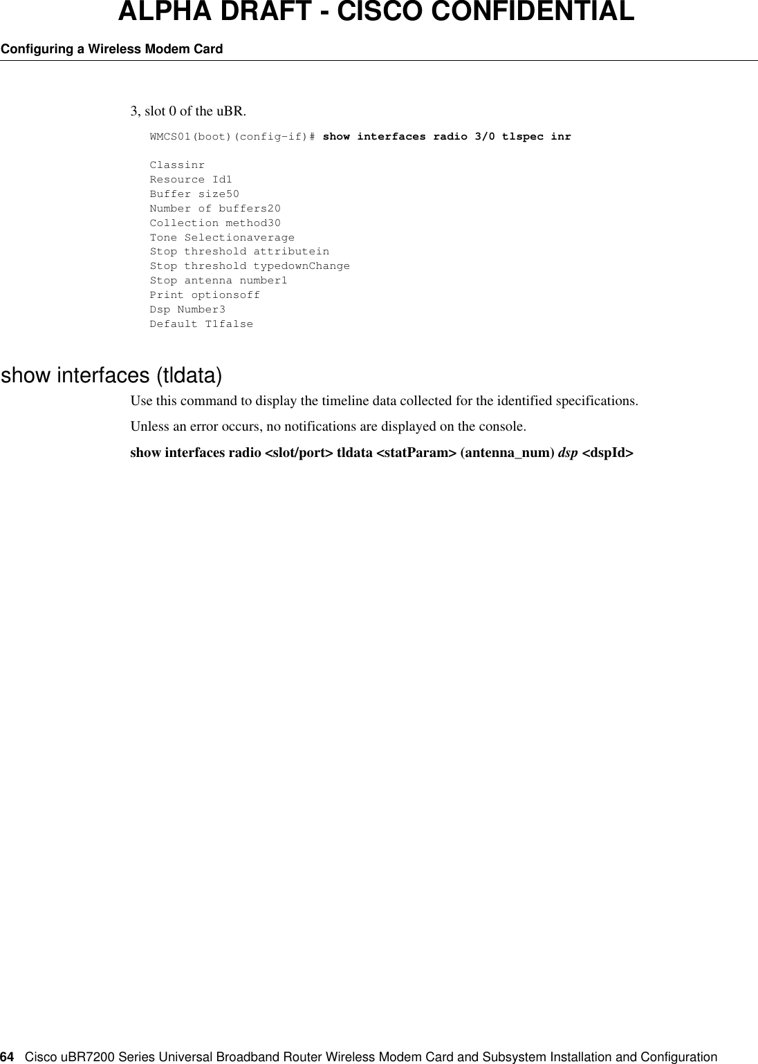
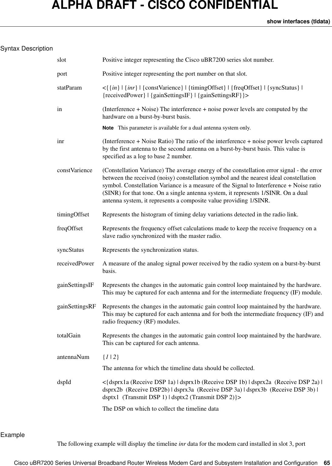
![62CiscouBR7200 Series Universal Broadband Router Wireless Modem Card and Subsystem Installation and ConfigurationConfiguring a Wireless Modem CardALPHA DRAFT - CISCO CONFIDENTIALWhen the threshold <inr> <lowThreshold> <2> is reached, the collection will stop and the results will be printed out.WMCS01(boot)(config-if)# radio timeline inr 640 dec 20 pre 2 tone average trigger inr lowThreshold 2show interfaces (tlspec)Use this command to display the details of the timeline specifications currently configured. If none of the optional parameters are specified then all the timeline specifications on the modem card are displayed. If the <statParam><antenna_num> combination only is specified, then the configuration setup on the default will be displayed. if the [dsp <dspId>] parameter is specified, then the configurations on that DSP will be displayed.Unless an error occurs, no notifications are displayed on the console. show interfaces radio <slot/port> tlspec [<statParam> (antenna_num) [dsp <dspId>]]](https://usermanual.wiki/Cisco-Systems/OFDM-MMDS2/User-Guide-38809-Page-62.png)

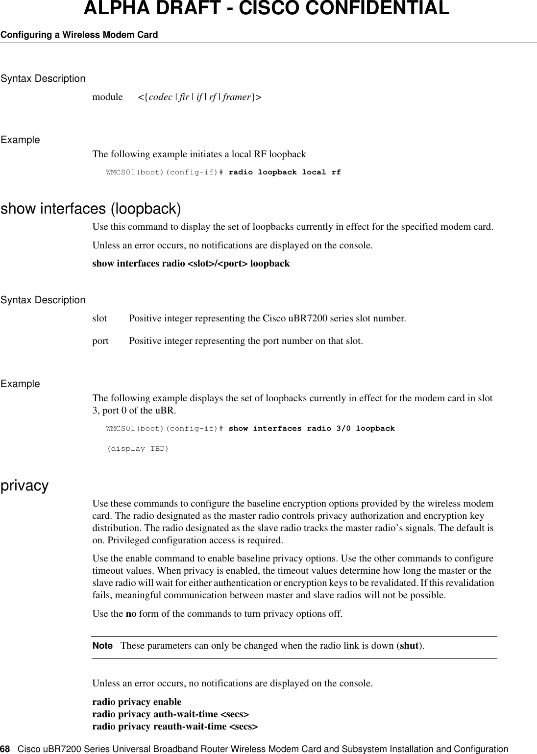
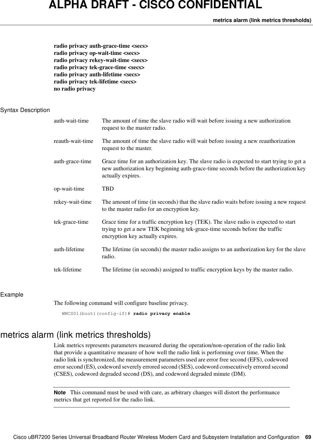
![66CiscouBR7200 Series Universal Broadband Router Wireless Modem Card and Subsystem Installation and ConfigurationConfiguring a Wireless Modem CardALPHA DRAFT - CISCO CONFIDENTIAL0 of the uBR.WMCS01(boot)(config-if)# show interfaces radio 3/0 tldata inrNumber of Points Captured=100 Trigger Location=540 :0000 0000 0000 0000 0000 0000 0000 0000 0000 000010 :0000 0000 0000 0000 0000 0000 0000 0000 0000 000020 :0000 0000 0000 0000 0000 0000 0000 0000 0000 000030 :0000 0000 0000 0000 0000 0000 0000 0000 0000 000040 :0000 0000 0000 0000 0000 0000 0000 0000 0000 000050 :FFFFFFFF FFFFFFFF 0000 0000 0000 0000 0000 0001 FFFFFFFF FFFFFFFF60 :0000 0002 FFFFFFFF FFFFFFFF 0000 0001 0000 0000 0000 000070 :0000 0000 0000 0001 FFFFFFFF FFFFFFFF 0000 0000 0000 000180 :FFFFFFFF FFFFFFFF 0000 0000 0000 0001 FFFFFFFF FFFFFFFF 0000 0000automatic repeat query (arq)Use these commands to configure the Automatic Repeat Query mechanism on the modem card to trade limited link bandwidth for redundancy in the link. The extra redundancy provides better error correction for a more stable link. Privileged configuration access is required.Use the no form of the command to reset the current ARQ settings to the default values.Use the radio arq <{on | off}> command to turn on or off the ARQ feature on the link.Use the radio arq reset command to reset the current ARQ values to consistent settings based on the channel-parameter configuration.NoteIf ARQ is turned off, the radio link may not get established in adverse environments.Unless an error occurs, no notifications are displayed on the console. radio arq <pctBw> <dataLatency> {BurstSize]no radio arqradio arq < {on | off}> radio arq resetSyntax DescriptionExampleThe following command sequence sets the ARQ mechanism for 0.01% of the bandwidth, a 20 millisecond latency value, and 20 consecutive ARQ codewords.WMCS01(boot)(config-if)# radio arq 1 20 20pctBw Positive number representing the peak percentage of the link bandwidth to be used for the ARQ mechanism. The value may be 1 to 10000 representing 0.01 to 100 percent of the available bandwidth.dataLatency Positive number specifying the expected latency value for normal data. Latency values are measured in milliseconds.BurstSize Positive number specifying the maximum number of consecutive ARQ codewords that will be transmitted. Smaller values result in lower jitter.](https://usermanual.wiki/Cisco-Systems/OFDM-MMDS2/User-Guide-38809-Page-66.png)
![CiscouBR7200 Series Universal Broadband Router Wireless Modem Card and Subsystem Installation and Configuration 67show interfaces (arq)ALPHA DRAFT - CISCO CONFIDENTIALshow interfaces (arq)Use this command to display the current ARQ configuration on the modem card.Unless an error occurs, no notifications are displayed on the console. show interfaces radio <slot/port> arqSyntax DescriptionDisplay ElementsExampleThe following command will display the ARQ configuration for the modem card in slot 3, port 0.WMCS01(boot)(config-if)# show interfaces radio 3/0 arq(Display TBD)loopbackUse this command to configure the specified module to loopback its data path at the specified subsystem. If no optional parameters are specified, a local IF loopback is established. Privileged configuration access is required.Use the no form of the command to remove the loopback specification. Unless an error occurs, no notifications are displayed on the console. radio loopback [local <module>]no radio loopback [local<module>]slot Positive integer representing the CiscouBR7200 series slot number.port Positive integer representing the port number on that slot.pctBW The maximum percent link bandwidth being used for ARQ.dataLatency Hardware will restrict the maximum latency for packet data to this value.BurstSize Currently configured burst size.OnOff Whether ARQ is turned on or off.ARQPeakBitRate The maximum possible peak bit rate that the link can handle given the current channel-parameter and ARQ settings.ARQMinBitRate The minimum bit rate that may be seen on the link given the current channel-parameter and ARQ settings.ARQMaxLatencyJitter The Maximum jitter expected on this link given the current configuration.](https://usermanual.wiki/Cisco-Systems/OFDM-MMDS2/User-Guide-38809-Page-67.png)
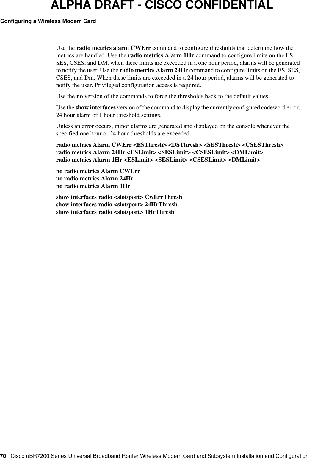
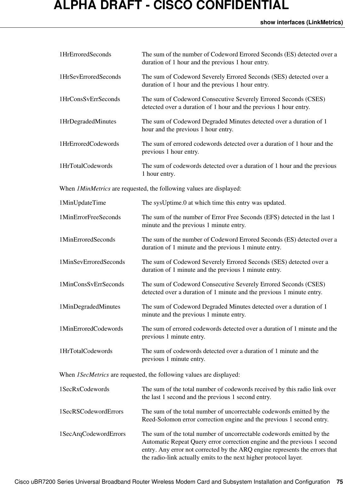
![72CiscouBR7200 Series Universal Broadband Router Wireless Modem Card and Subsystem Installation and ConfigurationConfiguring a Wireless Modem CardALPHA DRAFT - CISCO CONFIDENTIAL•If the link was consecutively errored for more than 1% of the time, an alarm will be generated.•If the link had more than 5 degraded minutes, an alarm will be generated.WMCS01(boot)(config-if)# radio metrics Alarm 1Hr 2400 360 36 5show interfaces (LinkMetrics)Link metrics represents parameters measured during the operation/non-operation of the radio link that provide a quantitative measure of how well the radio link is performing over time. All link metrics are measured in terms of Codewords. A Codeword is a unit of data transmission over the radio link. It contains information such as user’s data, error correction, and collation information so that successive Codewords may be reconstructed at the receiving end into the user’s data.There are two classes of link metrics:1Metrics that quantify how the link performed since the system was powered on:show interface radio <slot/port> linkMetrics (provides information since power on)show interface radio <slot/port> 24HrMetrics (provides information for the past 24 hours)2Metrics that quantify how the link performed when the two ends of the link were synchronized:show interface radio <slot/port> radio 1HrMetrics [delta] [numVals](provides details for the last 24 hours) show interface radio <slot/port> radio 1MinMetrics [delta] [numVals](provides details for the last 60 minutes)show interface radio <slot/port> radio 1SecMetrics [delta] [numVals](provides details for the last 60 seconds)show interface radio <slot/port> radio 1TickMetrics [delta] [numVals](provides details for the last N hardware ticks)Three categories of metrics are maintained by the radio link’s software and hardware:1Cumulative metrics where only one set is maintained for the entire collection period. LinkMetrics and 24HrMetrics are in this category.2Cumulative metrics where a table of values is maintained, providing metrics relating to the time period when the two ends of the link are synchronized. 1HrMetrics and 1MinMetrics are in this category.3Cumulative metrics where a table of values is maintained, providing metrics maintained by the hardware which is used to derive the information in categories 1 and 2. 1SecMetrics and 1TickMetrics are in this category.](https://usermanual.wiki/Cisco-Systems/OFDM-MMDS2/User-Guide-38809-Page-72.png)
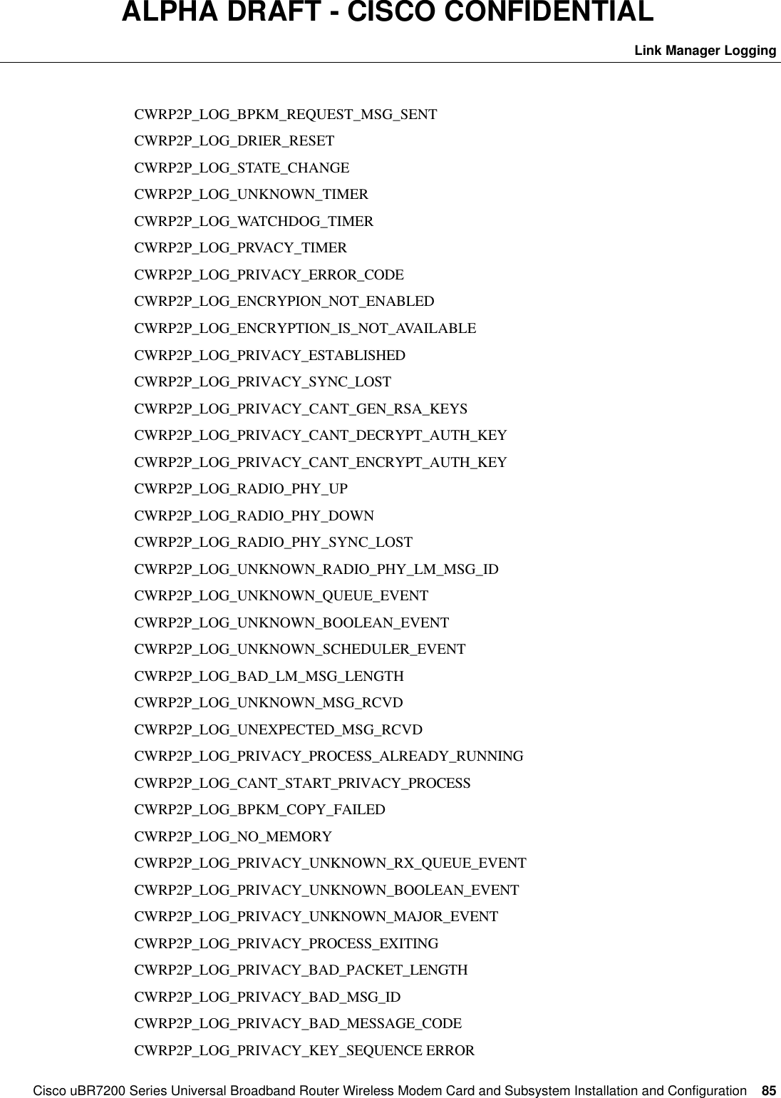
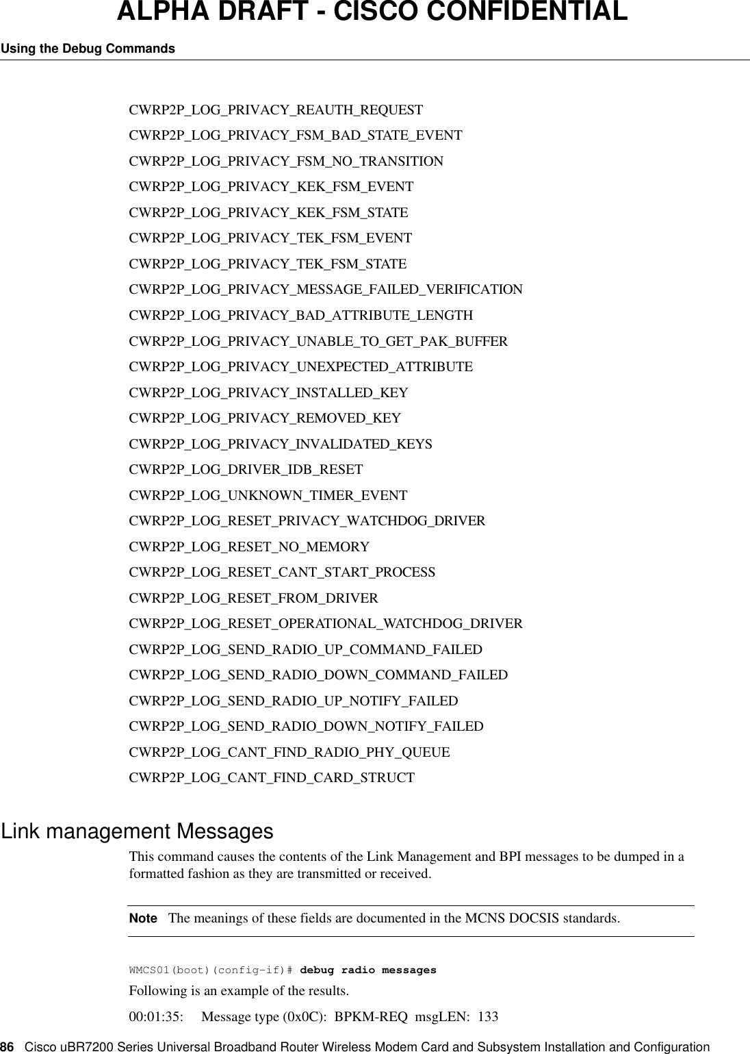
![84CiscouBR7200 Series Universal Broadband Router Wireless Modem Card and Subsystem Installation and ConfigurationUsing the Debug CommandsALPHA DRAFT - CISCO CONFIDENTIALUsing the Debug CommandsThe following commands are available to troubleshoot the (system). To use any of these commands, privileged configuration access is required.Use the command debug radio? to display a list of all available debug commands.Use the no version of the command to stop the process.Use the show debug command to display the current debug settings.debug radio <{lm_log | messages | phy}>no debug radioshow debugSyntax DescriptionDebug commands are divided into four general categories: Link Manager Logging, Link Management Messages, Physical Layer, and Radio Interface Specific Logging. Each of these is described below.Link Manager LoggingThis command controls the debugging of the Link Manager and Baseline Privacy Interface.WMCS01(boot)(config-if)# debug radio log [verbose]When this command is enabled, the following events can be reported.CWRP2P_LOG_BPKM_INVALID_CODE_IN_BPKM_MSGCWRP2P_LOG_BPKM_REPLY_MSG_RCVDCWRP2P_LOG_BPKM_REQUEST_MSG_RCVDCWRP2P_LOG_BPKM_REPLY_MSG_SENTlm_log log [verbose]phy <{radioLog | cwrLog}>radioLog radio <slot>/<port> <subModule>slot Positive integer representing the CiscouBR7200 series slot number.port Positive integer representing the port number on that slot.subModule <{cli | gal | snmp}> <logLevel>cli Tracing for radio interface CLI commands.gal Tracing for the GAL module.snmp Tracing for the radio SNMP module.logLevel <{all | controlFlow | dataFlow | validation | verbose}>cwrLog cwrLog <modName>modname Name of the module](https://usermanual.wiki/Cisco-Systems/OFDM-MMDS2/User-Guide-38809-Page-84.png)