Cisco Systems OFDM-MMDS2 Point to Point wireless data link User Manual alph6030
Cisco Systems Inc Point to Point wireless data link alph6030
Installation manual

1
Cisco Systems, Inc.
All rights reserved.
170 West Tasman Drive
San Jose, CA 95134-1706
USA
Cisco Systems, Inc.
Corporate Headquarters
Copyright © 1999
Text Part Number:
ALPHA DRAFT - CISCO CONFIDENTIAL
CiscouBR7200 Series Universal
Broadband Router Wireless Modem
Card and Subsystem Installation and
Configuration
Product Numbers: UBR-MCW-PDA, UBR-MCW-PDA=, UBR-WPFD, UBR-WPFD=,
UBR-ODU-PAA, UR-ODU-PAA=, UBR-ODD-01A, UBR-ODD-01A=, UBR-ODD-02A,
UBR-ODD-02A=, UBR-ODD-03A, UBR-ODD-03A=
This document explains how to install and configure the components for a high-speed point-to-point
fixed broadband wireless system using CiscouBR7200 series universal broadband routers. It
includes instructions for installing a wireless modem card, power feed panel, and outdoor unit, as
well as instructions for configuring and verifying the system and troubleshooting the configuration.
The CiscouBR7200 series consists of the 6-slot CiscouBR7246 (four modem card slots and two
port adapter slots) and the 3-slot CiscouBR7223 (two modem card slots and one port adapter slot).
NoteUse this configuration note in conjunction with the CiscouBR7200 Series Universal
Broadband Router Installation and Configuration Guide and Regulatory Compliance and Safety
Information for the CiscouBR7200 Series Universal Broadband Router that shipped with your
CiscouBR7200 series router, and the Cisco Wireless Broadband Router Site Planning Guide
The following sections are included in this document:
•If You Need More Information, page2
•Wireless Modem Card and Subsystem Overview, page2
•Installation Prerequisites, page7
•Removing and Installing a Wireless Modem Card, page12
•Installing a Power Feed Panel, page16
•Installing an Outdoor Unit, page21
•Configuring a Wireless Modem Card, page25
•Using the Debug Commands, page84
•Reference Information, page88
78-6030-01

2CiscouBR7200 Series Universal Broadband Router Wireless Modem Card and Subsystem Installation and Configuration
If You Need More Information
ALPHA DRAFT - CISCO CONFIDENTIAL
•Cisco Connection Online, page88
If You Need More Information
The Cisco IOS software running on your router contains extensive features and functionality. The
effective use of many of these features is easier if you have more information. For additional
information on configuring and maintaining the CiscouBR7200 series, the following
documentation resources are available:
•Cisco Documentation CD-ROM
Cisco documentation and additional literature are available in a CD-ROM package, which ships
with your product. The Documentation CD-ROM, a member of the Cisco Connection Family, is
updated monthly. Therefore, it might be more current than printed documentation. To order
additional copies of the Documentation CD-ROM, contact your local sales representative or call
customer service. The CD-ROM package is available as a single package or as an annual
subscription. You can also access Cisco documentation on the World Wide Web at
http://www.cisco.com, http://www-china.cisco.com, or http://www-europe.cisco.com.
If you are reading Cisco product documentation on the World Wide Web, you can submit
comments electronically. Click Feedback in the toolbar and select Documentation. After you
complete the form, click Submit to sent it to Cisco. we appreciate your comments.
•For Cisco IOS software configuration information, refer to the modular configuration and
modular command reference publications in the Cisco IOS software configuration
documentation set that corresponds to the software release installed on your Cisco hardware.
NoteYou can access CiscoIOS software configuration documentation on the World Wide Web
at http://www.cisco.com, http://www-china.cisco.com, http://www-europe.cisco.com.
•For hardware installation and maintenance information on the CiscouBR7200 series, refer to the
CiscouBR7200 Series Universal Broadband Router Installation and Configuration Guide that
shipped with your CiscouBR7246 or CiscouBR7223.
•For international agency compliance, safety, and statutory information for wide-area network
(WAN) interfaces for the CiscouBR7200 series, refer to the document Regulatory Compliance
and Safety Information for the CiscouBR7200 Series Universal Broadband Router.
•To obtain general information about documentation, refer to the "Cisco Connection Online"
section on page, or call customer service at 800553-6387 or 408526-7208. Customer service
hours are 5:00 a.m. to 6:00 p.m. Pacific time, Monday through Friday (excluding Cisco-observed
holidays). You can also send e-mail to cs-rep@cisco.com, or you can refer to the
CiscoInformation Packet that shipped with your router.
Wireless Modem Card and Subsystem Overview
The Cisco high-speed point-to-point fixed broadband wireless router system provides a fixed,
dedicated wireless link from one site to another. This link delivers 44 Mbps full-duplex data in a 12
MHz RF channel in the MDS band (2.500 to 2.690 GHz).
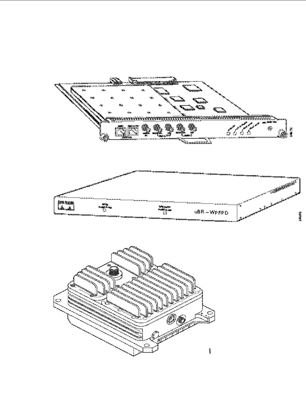
This broadband wireless router system consists of a CiscouBR7200 Series Universal Broadband
Router (CiscouBR7246, or CiscouBR7223) and one or more wireless modem cards (Figure1),
each with a power feed panel (Figure2), and outdoor unit (ODU) (Figure3). The diversity option
uses two outdoor units, one for each of two antennas.
CiscouBR7200 Series Universal Broadband Router Wireless Modem Card and Subsystem Installation and Configuration 3
Wireless Modem Card and Subsystem Overview
ALPHA DRAFT - CISCO CONFIDENTIAL
The wireless modem cards are installed in a CiscouBR7200 series router. Each modem card is
cabled to a power feed panel installed either in the same equipment rack as the router or mounted on
the wall. Cables from the power feed panel are connected to the outdoor unit which is installed either
on the antenna pole or on a wall in close proximity to the antenna. The system is managed via a
command line interface (CLI) or CiscoWorks.
Figure1Wireless Modem Card
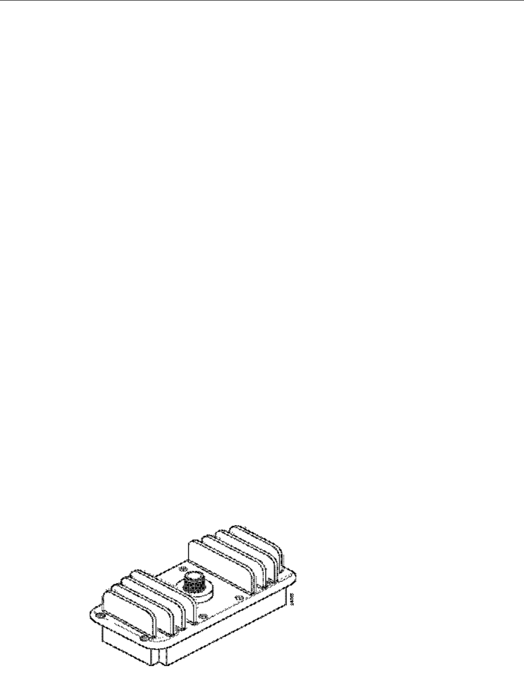
Figure2Power Feed Panel
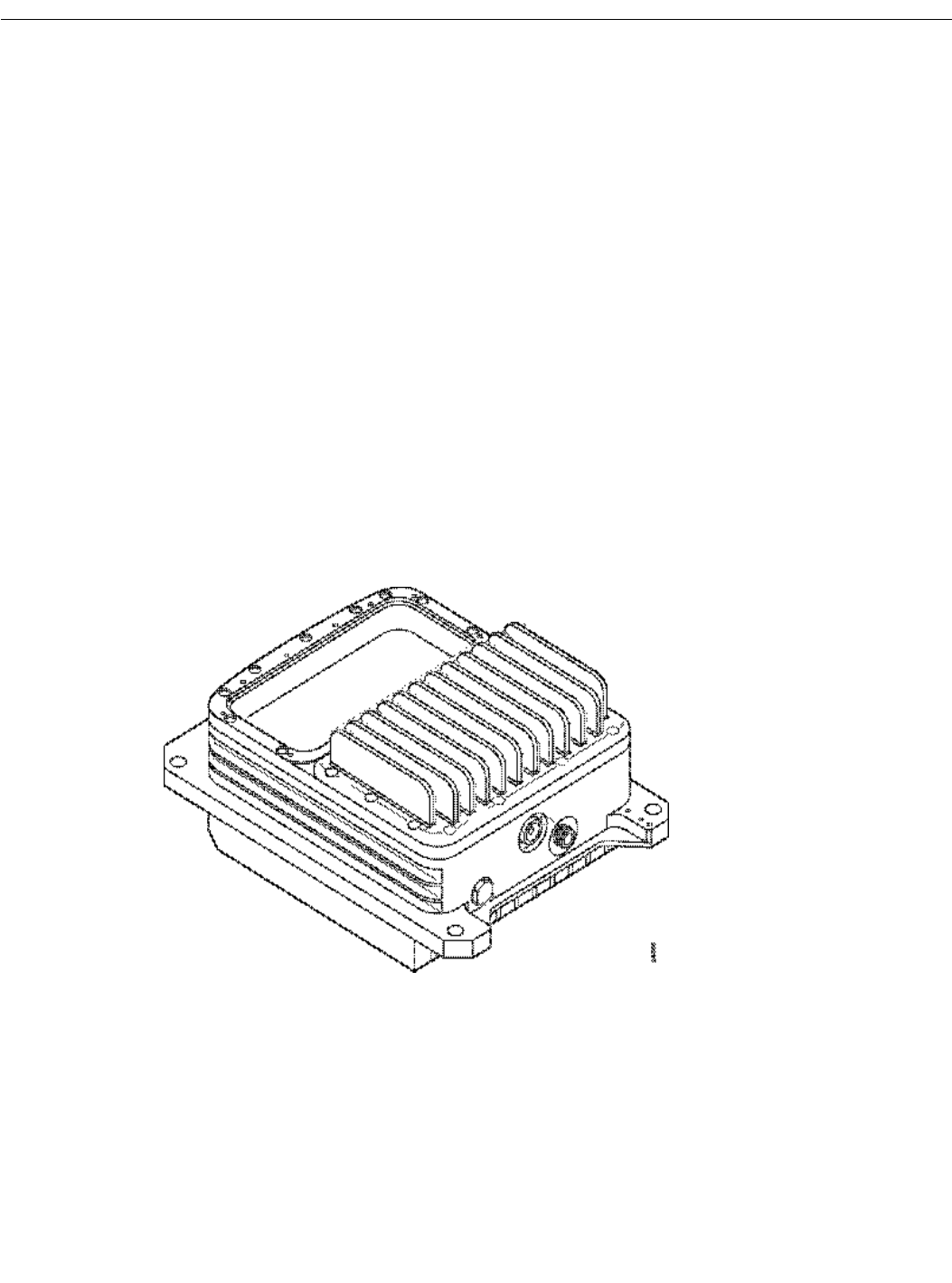
Figure3Outdoor Unit (ODU)
4CiscouBR7200 Series Universal Broadband Router Wireless Modem Card and Subsystem Installation and Configuration
Wireless Modem Card and Subsystem Overview
ALPHA DRAFT - CISCO CONFIDENTIAL
Wireless Modem Card
The wireless modem card provides the control and data interface to the system’s digital motherboard
and the radio frequency (RF) subsystem in the ODU. It also provides the up/down conversion from
baseband to intermediate frequency (IF).
Wireless modem cards consist of the following components:
•Main and diversity serial interface control connectors.
•10 MHz external reference clock connection.
•Monitor and Power Feed Panel connectors (Main and Diversity)
•Light-emitting diodes (LEDs) which provide a visual indication of the state of the modem card,
as well as providing a mechanism by which specific condition can be easily noted.
NoteThe appearance and meaning of these LEDs can be displayed or modified using the show
interface and led commands. These commands are described in the section "Configuring a
Wireless Modem Card" on
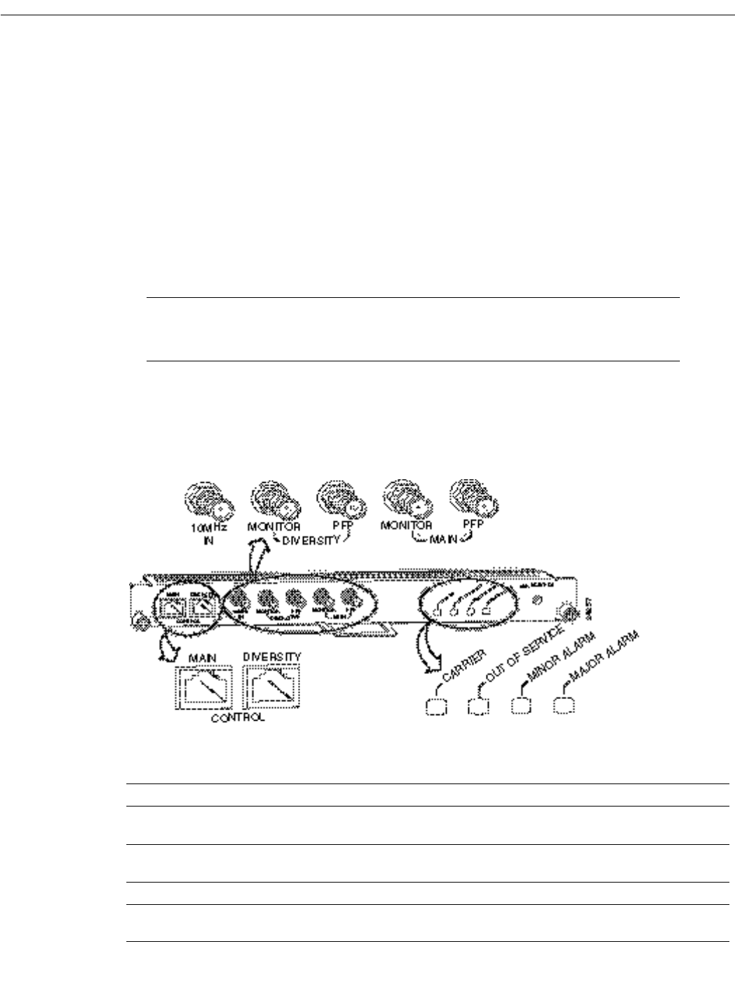
Figure4 shows the connectors and LEDs on the wireless modem card. Table1 describes the
functions of the connectors, and Table2 describes the functions of the LEDs.
Figure4Wireless Modem Card Connectors and LEDs
Table1Wireless Modem Card Connectors
Connector Type Function
Control - Main 8-pin RJ45 (female) Physical connection to Power Feed Panel for RF subsystem interface
control channel.
Control - Diversity 8-pin RJ45 (female) Physical connection to Power Feed Panel for RF subsystem interface
control channel (when diversity option is used).
10 MHz Input SMA (male) Connection for 10 MHz external reference clock.
Diversity - Monitor SMA (female) For connection to spectrum analyzer for test/troubleshooting purposes
(when diversity option is used).

CiscouBR7200 Series Universal Broadband Router Wireless Modem Card and Subsystem Installation and Configuration 5
Power Feed Panel
ALPHA DRAFT - CISCO CONFIDENTIAL
Power Feed Panel
The power feed panel provides DC power and Tx/Rx and reference signals to the ODU. In addition,
the unit contains circuit breakers and secondary lightning protection circuitry for both the IF and
control cables.
The power feed panel consists of the following components:
•Power LEDs on front and rear panel
•Connector ports
—Coaxial cable connection to the wireless modem card and ODU (Main and Diversity)
—Control cable connection ports to modem card and ODU (Main and Diversity)
•Power ON/OFF switches (Main and Diversity)
•DC power supply terminal block
Figure5 shows the front panel and Figure6 shows the rear panel of the power feed panel. Table3
describes the functions of the LEDs. Table4 describes the functions of the connectors.
Figure5Power Feed Panel (Front Panel)
Diversity - PFP SMA (female) 48 MHz reference, receive and transmit IF signals (when diversity option
is used).
Main - Monitor SMA (female) For connection to spectrum analyzer for test/troubleshooting purposes.
Main - PFP SMA (female) 48 MHz reference, receive and transmit IF signals.
Table2Wireless Modem Card LEDs
LED Function
Carrier LED Indicates the state of the radio link. When lit, the radio link is up.
Out of Service LED Indicates the service availability of the radio link. When lit, the radio link is still up, but not
available for use.
Minor Alarm LED When lit, indicates the occurrence of a minor alarm in the radio subsystem. The link is
degraded and may need maintenance action.
Major Alarm LED When lit, indicates the occurrence of a major alarm in the radio subsystem. The link is down.
Table1Wireless Modem Card Connectors (continued)
Connector Type Function
6CiscouBR7200 Series Universal Broadband Router Wireless Modem Card and Subsystem Installation and Configuration
Wireless Modem Card and Subsystem Overview
ALPHA DRAFT - CISCO CONFIDENTIAL
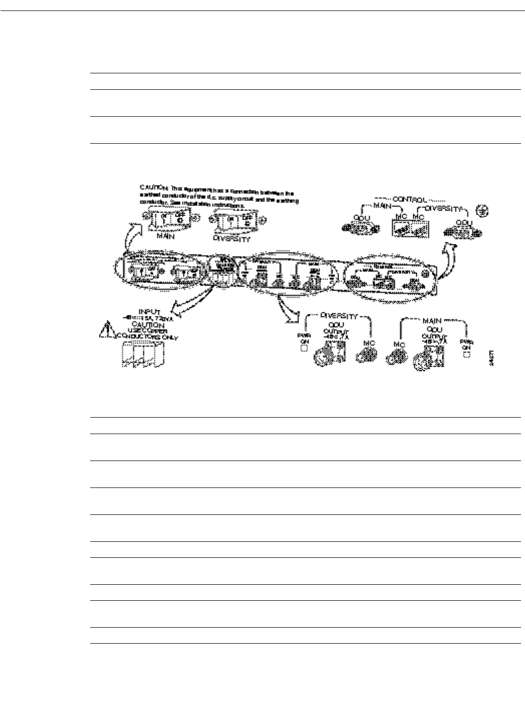
Figure6Power Feed Panel (Rear Panel)
Table3Power Feed Panel LEDs
LED Function
Main Power On
(visible on front and rear panel)
When lit, indicates that there is power going to the main ODU.
Diversity Power On
(visible on front and rear panel)
When lit, indicates that there is power going to the diversity ODU.
Table4Power Feed Panel Connectors
Connector Type Function
Main ODU Control DB9 (female) Physical connection to the main ODU for RF
subsystem interface.
Main MC (modem card) Control 8-pin RJ45 (female) Physical connection for RF subsystem interface
from modem card.
Diversity ODU Control DB9 (female) Physical connection to the diversity ODU for RF
subsystem interface.
Diversity MC (modem card) Control 8-pin RJ45 (female) Physical connection for RF subsystem interface
from modem card (if diversity option used).
Diversity ODU Output N-Type (female) Provides signal and power to the diversity ODU.
Diversity MC (modem card) SMA (female) 48 MHz reference, receive and transmit IF signals
from the modem card (if diversity option used).
Main ODU Output N-Type (female) Provides signal and power to the main ODU.
Main MC (modem card) SMA (female) 48 MHz reference, receive and transmit IF signals
from the modem card.
DC Power Input Pluggable terminal block Power source for the main and diversity ODUs.

CiscouBR7200 Series Universal Broadband Router Wireless Modem Card and Subsystem Installation and Configuration 7
Outdoor Unit (ODU)
ALPHA DRAFT - CISCO CONFIDENTIAL
Outdoor Unit (ODU)
The ruggedized ODU is the control and data interface to the indoor subsystems. It provides up/down
conversion from IF to RF frequencies and power amplification.
The outdoor unit consists of the following components:
•RF head
•Connector ports for IF input, control, and test
•Duplexor assembly with antenna connection
Figure7 shows the connectors on the outdoor subsystem, and Table5 describes their use.
Figure7Outdoor Unit Connectors
Installation Prerequisites
This section provides a list of parts and tools you need to remove and replace a wireless modem card
in the CiscouBR7200 series router, install the power feed panel in an equipment rack or on the wall,
and install the outdoor unit at the antenna site. This section also includes safety and ESD-prevention
guidelines to help you avoid injury to yourself and damage to the equipment.
Table5Outdoor Unit Connectors
Connector Type Function
Antenna connector N-type weatherized (female) Antenna connection
IF Input N-type weatherized (female) Carries receive and transmit IF signals and power
Control Lemo RF subsystem interface
Test Phono (female) Antenna alignment

8CiscouBR7200 Series Universal Broadband Router Wireless Modem Card and Subsystem Installation and Configuration
Installation Prerequisites
ALPHA DRAFT - CISCO CONFIDENTIAL
Parts and Tools
The following sections describe the parts and tools required to install each of the components. If you
need more detailed information regarding cables or connectors, refer to the Cisco Wireless
Broadband Router Site Planning Guide.
Wireless Modem Card
You need the following tools and parts to remove and replace a wireless modem card. If you need
additional equipment, contact a service representative for ordering information.
•New wireless modem card
•No.2 Phillips screwdriver
•5/16 in. open end wrench
•Your own ESD-prevention equipment or the disposable grounding wrist strap included with all
upgrade kits, FRUs, and spares
•Antistatic mat or surface
•Static shielding bag
•Cable with RJ45 connectors and coaxial cable with SMA connectors for connections between the
modem card and the power feed panel. (Standard sets of these cables can be purchased from
Cisco.)
•SMA (male) to BNC (male) adapter cable and coaxial cable for cabling the 10 MHz clock.
Power Feed Panel
You need the following tools and parts to install the power feed panel in an equipment rack. If you
need additional equipment, contact a service representative for ordering information.
•Power feed panel
•No.2 Phillips screwdriver
•Bracket kit (provided)
•Rack mount or wall mount screws
•1/8 in. blade screwdriver
•5/16 in. open end wrench
•Cables with N-type (male) connectors for IF control
•Cables with DB9 (male) and Lemo (male) connectors (Lemo connector provided)
•48VDC power supply
Outdoor Unit
You need the following tools and parts to install the outdoor unit. If you need additional equipment,
contact a service representative for ordering information.
•Outdoor unit
•Duplexor assembly
•No.2 Phillips screwdriver

CiscouBR7200 Series Universal Broadband Router Wireless Modem Card and Subsystem Installation and Configuration 9
Software and Hardware Requirements
ALPHA DRAFT - CISCO CONFIDENTIAL
•Mounting kit (provided)
•Cable with N-type (male) connectors to cable the ODU to the antenna
•Mini-phone with 3.5 mm mono phone plug to use for antenna alignment tasks
Software and Hardware Requirements
The following hardware is required:
•Configured CiscouBR7200 series router
The following software is required:
•The CiscouBR7200 series router must be running Cisco IOS Release 12.0(6)XA or later.
Safety Guidelines
Following are safety guidelines that you should follow when working with any equipment that
connects to electrical power or telephone wiring.
Safety Warnings
WarningThis warning symbol means danger. You are in a situation that could cause bodily injury.
Before you work on any equipment, be aware of the hazards involved with electrical circuitry and
be familiar with standard practices for preventing accidents. To see translations of the warnings that
appear in this publication, refer to the Regulatory Compliance and Safety Information document that
accompanied this device.
Waarschuwing Dit waarschuwingssymbool betekent gevaar. U verkeert in een situatie die
lichamelijk letsel kan veroorzaken. Voordat u aan enige apparatuur gaat werken, dient u zich bewust
te zijn van de bij elektrische schakelingen betrokken risico's en dient u op de hoogte te zijn van
standaard maatregelen om ongelukken te voorkomen. Voor vertalingen van de waarschuwingen die
in deze publicatie verschijnen, kunt u het document Regulatory Compliance and Safety Information
(Informatie over naleving van veiligheids- en andere voorschriften) raadplegen dat bij dit toestel is
ingesloten.
VaroitusTämä varoitusmerkki merkitsee vaaraa. Olet tilanteessa, joka voi johtaa ruumiinvammaan.
Ennen kuin työskentelet minkään laitteiston parissa, ota selvää sähkökytkentöihin liittyvistä
vaaroista ja tavanomaisista onnettomuuksien ehkäisykeinoista. Tässä julkaisussa esiintyvien
varoitusten käännökset löydät laitteen mukana olevasta Regulatory Compliance and Safety
Information -kirjasesta (määräysten noudattaminen ja tietoa turvallisuudesta).
Attention Ce symbole d'avertissement indique un danger. Vous vous trouvez dans une situation
pouvant causer des blessures ou des dommages corporels. Avant de travailler sur un équipement,
soyez conscient des dangers posés par les circuits électriques et familiarisez-vous avec les
procédures couramment utilisées pour éviter les accidents. Pour prendre connaissance des
traductions d’avertissements figurant dans cette publication, consultez le document Regulatory
Compliance and Safety Information (Conformité aux règlements et consignes de sécurité) qui
accompagne cet appareil.
Warnung Dieses Warnsymbol bedeutet Gefahr. Sie befinden sich in einer Situation, die zu einer
Körperverletzung führen könnte. Bevor Sie mit der Arbeit an irgendeinem Gerät beginnen, seien Sie
sich der mit elektrischen Stromkreisen verbundenen Gefahren und der Standardpraktiken zur
Vermeidung von Unfällen bewußt. Übersetzungen der in dieser Veröffentlichung enthaltenen

10CiscouBR7200 Series Universal Broadband Router Wireless Modem Card and Subsystem Installation and Configuration
Installation Prerequisites
ALPHA DRAFT - CISCO CONFIDENTIAL
Warnhinweise finden Sie im Dokument Regulatory Compliance and Safety Information
(Informationen zu behördlichen Vorschriften und Sicherheit), das zusammen mit diesem Gerät
geliefert wurde.
Avvertenza Questo simbolo di avvertenza indica un pericolo. La situazione potrebbe causare
infortuni alle persone. Prima di lavorare su qualsiasi apparecchiatura, occorre conoscere i pericoli
relativi ai circuiti elettrici ed essere al corrente delle pratiche standard per la prevenzione di incidenti.
La traduzione delle avvertenze riportate in questa pubblicazione si trova nel documento Regulatory
Compliance and Safety Information (Conformità alle norme e informazioni sulla sicurezza) che
accompagna questo dispositivo.
Advarsel Dette varselsymbolet betyr fare. Du befinner deg i en situasjon som kan føre til
personskade. Før du utfører arbeid på utstyr, må du vare oppmerksom på de faremomentene som
elektriske kretser innebærer, samt gjøre deg kjent med vanlig praksis når det gjelder å unngå ulykker.
Hvis du vil se oversettelser av de advarslene som finnes i denne publikasjonen, kan du se i
dokumentet Regulatory Compliance and Safety Information (Overholdelse av forskrifter og
sikkerhetsinformasjon) som ble levert med denne enheten.
Aviso Este símbolo de aviso indica perigo. Encontra-se numa situação que lhe poderá causar danos
físicos. Antes de começar a trabalhar com qualquer equipamento, familiarize-se com os perigos
relacionados com circuitos eléctricos, e com quaisquer práticas comuns que possam prevenir
possíveis acidentes. Para ver as traduções dos avisos que constam desta publicação, consulte o
documento Regulatory Compliance and Safety Information (Informação de Segurança e Disposições
Reguladoras) que acompanha este dispositivo.
¡Advertencia! Este símbolo de aviso significa peligro. Existe riesgo para su integridad física. Antes
de manipular cualquier equipo, considerar los riesgos que entraña la corriente eléctrica y
familiarizarse con los procedimientos estándar de prevención de accidentes. Para ver una traducción
de las advertencias que aparecen en esta publicación, consultar el documento titulado Regulatory
Compliance and Safety Information (Información sobre seguridad y conformidad con las
disposiciones reglamentarias) que se acompaña con este dispositivo.
Varning! Denna varningssymbol signalerar fara. Du befinner dig i en situation som kan leda till
personskada. Innan du utför arbete på någon utrustning måste du vara medveten om farorna med
elkretsar och känna till vanligt förfarande för att förebygga skador. Se förklaringar av de varningar
som förkommer i denna publikation i dokumentet Regulatory Compliance and Safety Information
(Efterrättelse av föreskrifter och säkerhetsinformation), vilket medföljer denna anordning.
Electrical Equipment Guidelines
Follow these basic guidelines when working with any electrical equipment:
•Before beginning any procedures requiring access to the chassis interior, locate the emergency
power-off switch for the room in which you are working.
•Disconnect all power and external cables before moving a chassis.
•Do not work alone if potentially hazardous conditions exist.
•Never assume that power has been disconnected from a circuit; always check.
•Do not perform any action that creates a potential hazard to people or makes the equipment
unsafe.
•Carefully examine your work area for possible hazards such as moist floors, ungrounded power
extension cables, and missing safety grounds.
CiscouBR7200 Series Universal Broadband Router Wireless Modem Card and Subsystem Installation and Configuration 11
Safety Guidelines
ALPHA DRAFT - CISCO CONFIDENTIAL
Telephone Wiring Guidelines
Use the following guidelines when working with any equipment that is connected to telephone
wiring or to other network cabling:
•Never install telephone wiring during a lightning storm.
•Never install telephone jacks in wet locations unless the jack is specifically designed for wet
locations.
•Never touch uninsulated telephone wires or terminals unless the telephone line has been
disconnected at the network interface.
•Use caution when installing or modifying telephone lines.
Preventing Electrostatic Discharge Damage
Electrostatic discharge (ESD) damages equipment and impairs electrical circuitry. ESD occurs when
printed circuit boards are improperly handled and results in complete or intermittent failures
The network processing engine, I/O controller, port adapters, and wireless modem cards consist of
a printed circuit board that is fixed in a metal carrier. Electromagnetic interference (EMI) shielding,
connectors, and a handle are integral components of the carrier. Handle the network processing
engine, I/O controller, port adapters, and wireless modem cards by their carrier edges and handles;
never touch the printed circuit board when handling either component.
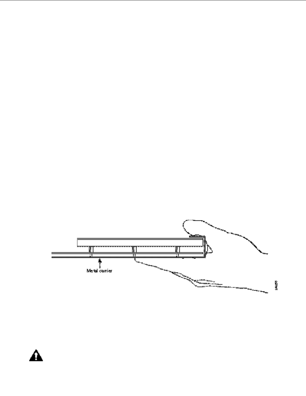
Figure8 shows the location of a printed circuit board when it is installed in a network processing
engine, I/O controller, or CiscouBR7200 series modem card metal carrier. Do not touch the printed
circuit board when handling either component.
Figure8Handling the Cisco uBR7200 Series Wireless Modem Cards—Side View
Although the metal carrier helps to protect the printed circuit boards from ESD, wear a preventive
antistatic strap whenever handling the network processing engine, I/O controller, port adapters, or
wireless modem cards. Ensure that the strap makes good skin contact and connect the strap’s clip to
an unpainted chassis surface to safely channel unwanted ESD voltages to ground.
If no wrist strap is available, ground yourself by touching the metal part of the chassis.
CautionMake sure to tighten the captive installation screws on the network processing engine, the
I/O controller, and the wireless modem cards (use a number2 Phillips screwdriver). These screws
prevent accidental removal, provide proper grounding for the router, and help to ensure that the
network processing engine, I/O controller, and modem cards are properly seated in the router
midplane.

12CiscouBR7200 Series Universal Broadband Router Wireless Modem Card and Subsystem Installation and Configuration
Removing and Installing a Wireless Modem Card
ALPHA DRAFT - CISCO CONFIDENTIAL
Following are guidelines for preventing ESD damage:
•Always use an ESD wrist strap or ankle strap when installing or replacing the network processing
engine, I/O controller, port adapters, or modem cards. Ensure that the ESD strap makes contact
with your skin.
•Handle the network processing engine, I/O controller, port adapters, or modem cards by their
metal carrier edges and handles only; avoid touching the printed circuit board components or any
connector pins.
•When removing the network processing engine, I/O controller, port adapters, or wireless modem
cards, place them on an antistatic surface with the printed circuit board components facing
upward, or in a static shielding bag. If you are returning an I/O controller, network processing
engine, port adapter, or modem card to the factory, immediately place it in a static shielding bag.
CautionPeriodically check the resistance value of the antistatic strap. The measurement should be
within the range of 1 and 10 megohm (Mohm).
Compliance with U.S. Export Laws and Regulations Regarding Encryption
This product performs encryption (in the baseline privacy feature) and is regulated for export by the
U.S. Government. Following is specific information regarding compliance with U.S. export laws and
regulations for encryption products:
•This product is not authorized fur use by persons located outside the United States and Canada
that do not have export license authority from the U.S. Government.
•This product may not be exported outside the U.S. and Canada either by physical or electronic
means without the prior written approval of the U.S. Government.
•Persons outside the U.S. and Canada may not reexport, resell, or transfer this product by either
physical or electronic means without prior written approval of the U.S. Government.
Removing and Installing a Wireless Modem Card
The following sections explain how to remove and replace or install a wireless modem card in a
CiscouBR7200 series router.
Removing a Wireless Modem Card
The following procedures explain how to remove a wireless modem card from a CiscouBR7200
series router:
Step1Attach an ESD-preventive wrist strap between you and an unfinished chassis surface.
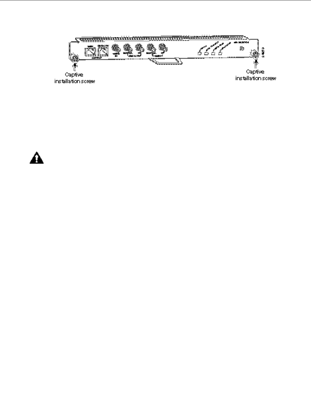
Step2Unscrew the captive installation screws on the front of the wireless modem card. (See
Figure9.)
CiscouBR7200 Series Universal Broadband Router Wireless Modem Card and Subsystem Installation and Configuration 13
Installing or Replacing a Wireless Modem Card
ALPHA DRAFT - CISCO CONFIDENTIAL
Figure9Captive Installation Screws
Step3Grasp the handle on the wireless modem card and carefully pull the modem card from the
midplane, about halfway out of its slot. If you are removing a blank modem card, pull the
blank modem card all the way out of the chassis slot.
Step4With the wireless modem card halfway out of the slot, disconnect all cables from the front
of the modem card.
Step5After disconnecting the cables, pull the modem card from its chassis slot.
CautionAlways handle the wireless modem card by the carrier edges and handle; never touch the
modem card’s components or connector pins. (See Figure8.)
Step6Place the modem card on an antistatic surface with its components facing upward, or in
a static shielding bag. If the modem card will be returned to the factory, immediately
place it in a static shielding bag.
This completes the procedure for removing a wireless modem card from the CiscouBR7200 series
router.
Installing or Replacing a Wireless Modem Card
Complete the following steps to install or replace a wireless modem card in the CiscouBR7200
series router:
Step1Attach an ESD-preventive wrist strap between you and an unfinished chassis surface.
Step2Use both hands to grasp the modem card by its metal carrier edges and position the
modem card so that its components are downward. (See Figure8.)
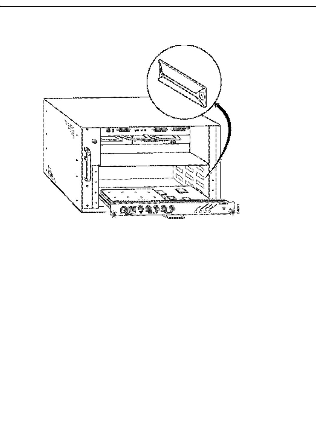
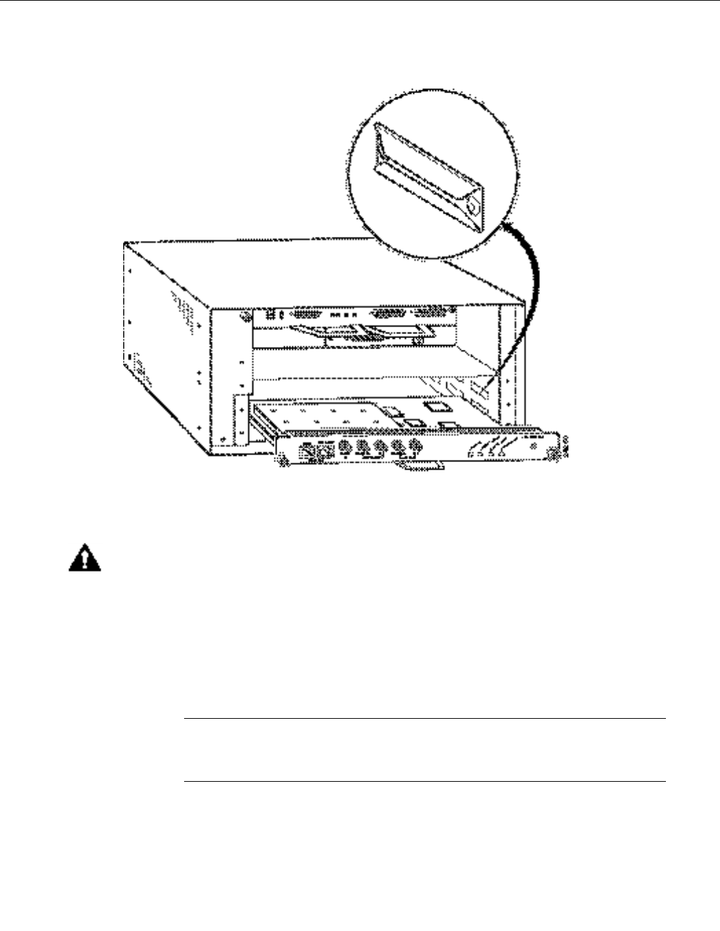
Step3Align the left and right edges of the modem card metal carrier between the guides in the
modem card slot. (For the CiscouBR7246, see Figure10. For the CiscouBR7223, see
Figure11.)
14CiscouBR7200 Series Universal Broadband Router Wireless Modem Card and Subsystem Installation and Configuration
Removing and Installing a Wireless Modem Card
ALPHA DRAFT - CISCO CONFIDENTIAL
Figure10 Aligning the Wireless Modem Card Metal Carrier Between the Slot Guides
(CiscouBR7246 Shown)
CiscouBR7200 Series Universal Broadband Router Wireless Modem Card and Subsystem Installation and Configuration 15
Installing or Replacing a Wireless Modem Card
ALPHA DRAFT - CISCO CONFIDENTIAL
Figure11 Aligning the Wireless Modem Card Metal Carrier Between the Slot Guides
(CiscouBR7223 Shown)
Step4With the metal carrier aligned in the slot guides, gently slide the modem card halfway into
the modem card slot.
CautionDo not slide the modem card all the way into the slot until you have connected all required
cables. Trying to do so will disrupt normal operation of the router.
Step5With the modem card halfway in the slot, connect all required cables to the front of the
modem card. (See the section "Cabling a Wireless Modem Card" on Page3.)
Step6After connecting all required cables, carefully slide the modem card all the way into the
slot until you feel the card’s connectors mate with the midplane.
Step7Tighten the captive installation screws on the modem card. (See Figure9.)
NoteIf the modem card captive installation screws do not tighten all the way, the card
is not completely seated in the midplane. Carefully pull the modem card halfway out of
the slot, reinsert it, and tighten the captive installation screws.
This completes the procedure for installing a wireless modem card in the CiscouBR7200 series
router.
16CiscouBR7200 Series Universal Broadband Router Wireless Modem Card and Subsystem Installation and Configuration
Installing a Power Feed Panel
ALPHA DRAFT - CISCO CONFIDENTIAL
Cabling a Wireless Modem Card
Attaching the RF Control Cables
Insert the RJ45 connector on the control cable into the Main Control connector port. If you will be
using the diversity option, use a second cable and attach it to the Diversity Control connector port.
Attaching the IF and Monitor Cables
Connect one end of the IF signal cable to the Main PFP port. If you will be using the diversity option,
use a second cable and attach it to the Diversity PFP port.
(Optional) To use a spectrum analyzer to test or troubleshoot the signal on the modem card, attach
it to the Main Monitor port or Diversity Monitor port.
Cabling the 10 MHz Clock
To connect to a 10 MHz clock, connect an SMA to BMC adapter to the 10 MHz IN connector port.
Attach the clock cable’s BNC connector to the adapter.
This completes the procedure for installing a wireless modem card in the CiscouBR7200 series
router.
Installing a Power Feed Panel
A power feed panel can be mounted in a 19-inch rack or mounted on a wall. The unit can be
co-located with the router or placed near the outdoor unit, depending on your site requirements.
NoteAt least one rack unit space must exist between the uBR and the power feed panel or between
multiple power feed panels.
Rack-Mounting a Power Feed Panel
A power feed panel can be rack-mounted with either the front panel or the rear panel facing forward
depending on the cable handling requirements of your site, or in a center-mount telco rack. The
power LEDs are visible on both the front and rear panels.
Attaching the Brackets
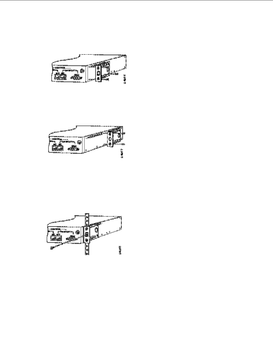
To install a power feed panel with the front panel facing forward, attach the brackets to both sides of
the unit as shown in Figure12.
Figure12 Bracket Installation - Front Panel Forward
CiscouBR7200 Series Universal Broadband Router Wireless Modem Card and Subsystem Installation and Configuration 17
Rack-Mounting a Power Feed Panel
ALPHA DRAFT - CISCO CONFIDENTIAL
To install a power feed panel with the rear panel facing forward, attach the brackets to both sides of
the unit as shown in Figure13.
Figure13 Bracket Installation - Rear Panel Forward
To install a power feed panel in a center-mount telco rack, attach the brackets to both sides of the
unit as shown in Figure14.
Figure14 Telco Bracket Installation - Rear Panel Forward
Installing the Power Feed Panel in the Rack
After the brackets are secured, attach the brackets on both sides of the power feed panel to the rack
as shown in Figure15.
Figure15 Attaching the Power Feed Panel to a Rack
Wall-Mounting the Power Feed Panel
To wall-mount the unit, use the same brackets as those used to install the power feed panel in an
equipment rack.
Use the following steps to wall-mount the power feed panel:
Step1Attach the brackets to both sides of the power feed panel as shown in Figure16.
18CiscouBR7200 Series Universal Broadband Router Wireless Modem Card and Subsystem Installation and Configuration
Installing a Power Feed Panel
ALPHA DRAFT - CISCO CONFIDENTIAL
Figure16 Attaching the Wall Mount Brackets
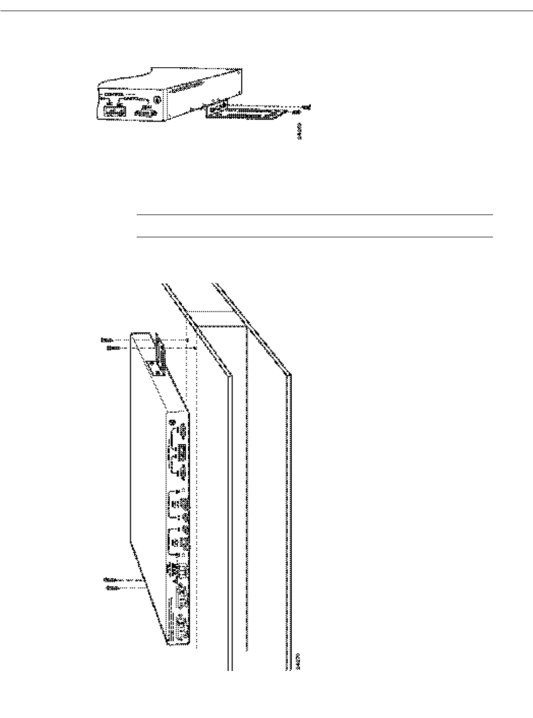
Step2Attach the power feed panel to the wall as shown in Figure17, using (customer provided)
screws and anchors. To best support the power feed panel and cables, attach the brackets
so that the screws align with a vertical wall stud. (SeeFigure17.) This position will
prevent the unit from pulling away from the wall when the cables are attached.
Note
Figure17 Wall-Mounting the Power Feed Panel
CiscouBR7200 Series Universal Broadband Router Wireless Modem Card and Subsystem Installation and Configuration 19
Wiring the DC Power
ALPHA DRAFT - CISCO CONFIDENTIAL
Wiring the DC Power
Follow the procedures in this section to wire the DC power.
NoteThe color coding of DC-input power supply leads depends on the color coding of the DC
power source at your site. Typically, green or green/yellow is used for ground, black is used for +48V
(return), and red or white is used for –48V. Make certain the lead color coding you choose for the
DC-input power supply matches lead color coding at the DC power source.
WarningBefore working on equipment that is connected to power lines, remove jewelry (including
rings, necklaces, and watches). metal objects will heat up when connected to power and ground and
can cause serious burns or weld the metal object to the terminals.
WarningBefore performing any of the following procedures, ensure that the power is removed
from the DC circuit. To ensure that all power is OFF, locate the circuit breaker on the panel board
that services the DC circuit, switch the circuit breaker to the OFF position, and tape the switch
handle of the circuit breaker in the OFF position.
Wiring the DC power consists of attaching the wires of the DC power source to a removable wiring
block, then plugging that block into the connection on the power feed panel. Refer to Figure19 and
Figure20 and follow these steps.
Step1Ensure that the leads are disconnected from the power source.
WarningThe Illustration shows the DC power supply terminal block. Wire the DC power supply
using the appropriate wire terminations at the wiring end, as illustrated. The proper wiring sequence
is ground to ground, positive to positive (line to +), and negative to negative (neutral to –). Note that
the ground wire should always be connected first and disconnected last.
WarningWhen stranded wiring is required, use approved wiring terminations, such as closed-loop
or spade-type with upturned lugs. These terminations should be the appropriate size for the wires
and should clamp both the insulation and the conductor.
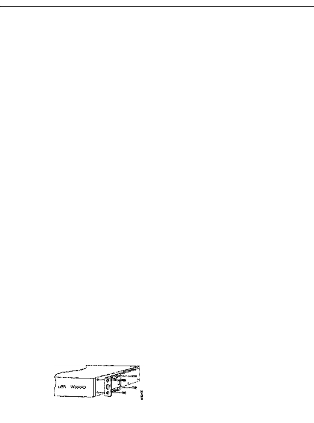
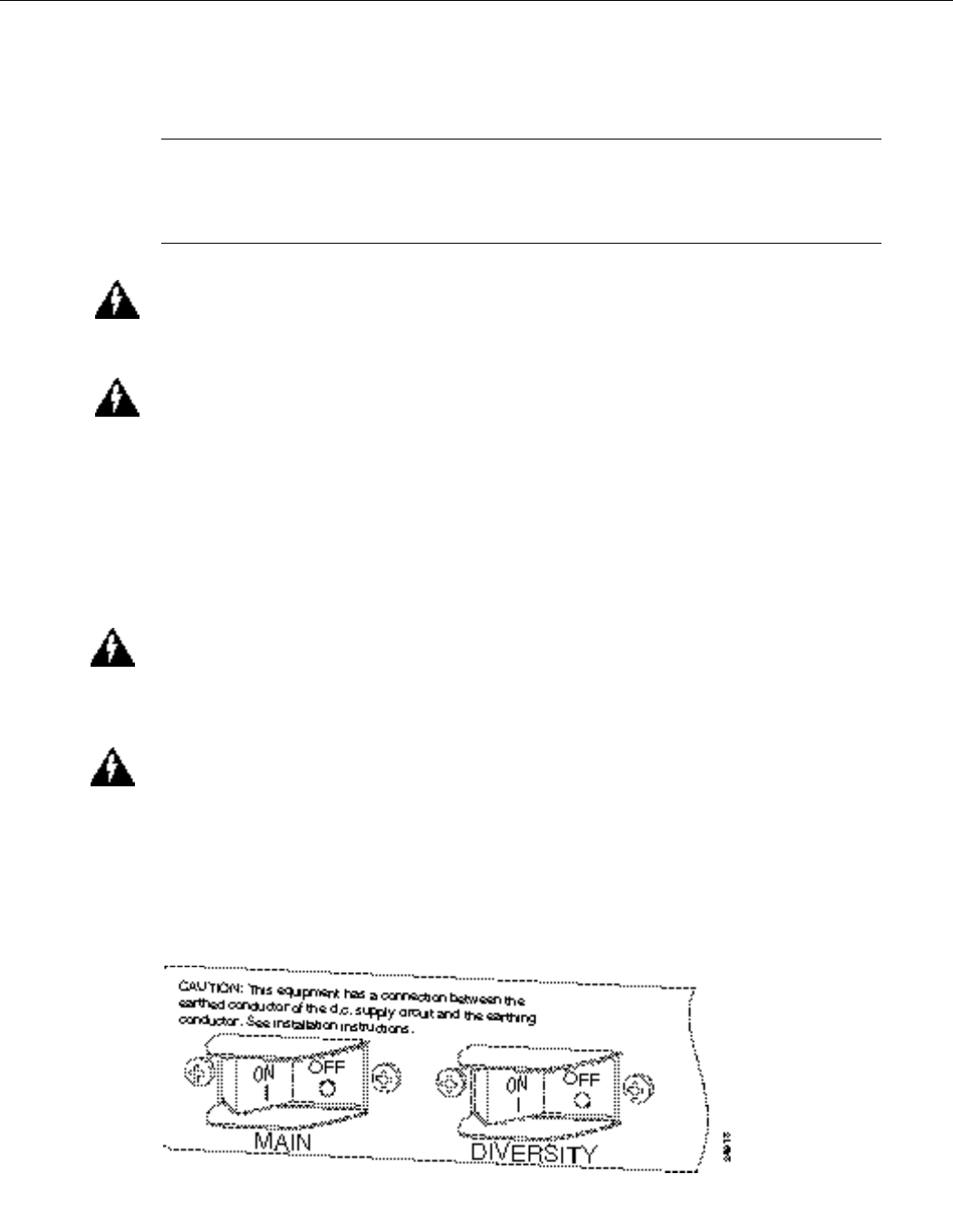
Step2Ensure that the power switch for both the main and diversity ODU are in the OFF (0)
position. (See Figure18.)
Figure18 ODU Power Switches
20CiscouBR7200 Series Universal Broadband Router Wireless Modem Card and Subsystem Installation and Configuration
Installing a Power Feed Panel
ALPHA DRAFT - CISCO CONFIDENTIAL
Step3Using a wire stripper, strip approximately 0.55 in. (14 mm) from the +48V, –48V and
ground leads.
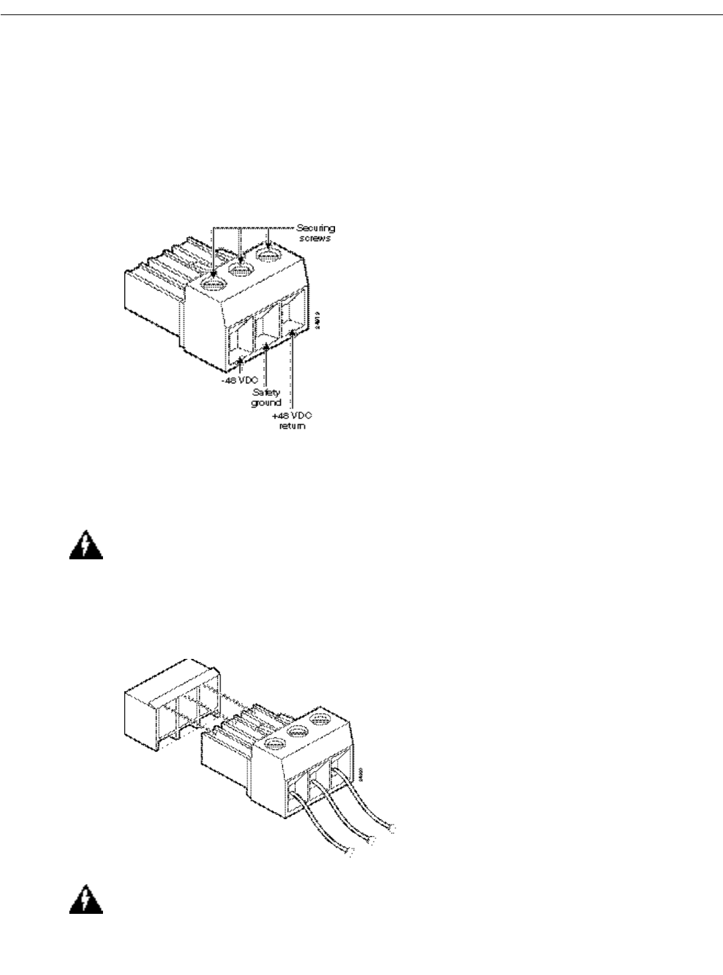
Step4Insert the stripped ends of the wire in the removable wiring block according to the scheme
in Figure19. Figure19 illustrates the polarity of each connection. The connection on the
left is for the –48VDC wire, the middle connection is for safety ground. The connection
on the right is for the positive return wire.
Figure19 Wiring Connections
Secure the wires using the 1/8 in. blade screwdriver to tighten the screws in the top of the
terminal block.
Step5Connect the DC input wiring to the DC source.
WarningFor personal safety, the green or green/yellow wire must connect to safety (earth) ground
at both the equipment and supply side of the DC wiring.
Step6Plug the terminal block into the receptacle on the power feed panel. (See Figure20.)
Figure20 Plugging the Terminal Block into the Receptacle
WarningAfter wiring the DC power supply, remove the tape from the circuit breaker switch handle
and reinstate power by moving the handle of the circuit breaker to the ON position.
CiscouBR7200 Series Universal Broadband Router Wireless Modem Card and Subsystem Installation and Configuration 21
Cabling the Power Feed Panel
ALPHA DRAFT - CISCO CONFIDENTIAL
Cabling the Power Feed Panel
Connecting the Control Cables (from the Modem Card)
Attach the end of the control cable coming from the Control-Main port on the modem card to the
Control-Main/MC port on the power feed panel. If you will be using the diversity option, also attach
the second control cable coming from the Control-Diversity port on the modem card to the
Control-Diversity/MC port on the power feed panel.
Connecting the Control Cables (to the ODU)
Attach a cable with a DB9 connector to the Control-Main/ODU port on the power feed panel. If you
will be using the diversity feature, attach a second cable to the Control-Diversity/ODU port.
Connecting the IF Cables (from the Modem Card)
Connect the cables coming from the Main/PFP port of the modem card to the Main/MC port on the
power feed panel. If you will be using the diversity feature, also connect the cable coming from the
Diversity/PFP port of the modem card to the Diversity/MC port on the power feed panel.
Connecting the IF Cables (to the ODU)
Attach one end of the IF cable to the Main-ODU/Output connector. If you will be using the diversity
feature, attach a second cable to the Diversity-ODU/Output connector.
This completes the procedure for installing and cabling a power feed panel.
Installing an Outdoor Unit
Installing an outdoor unit (ODU) requires the installation of the duplexor assembly prior to
mounting the ODU either on an antenna pole or on a wall.
Installing the Duplexor in the Outdoor Unit
The duplexor acts as a filter for Tx/Rx isolation. The duplexor assembly is shipped as a separate unit
based on the RF channel plan you have selected for your installation.
Figure21 Duplexor Assembly
22CiscouBR7200 Series Universal Broadband Router Wireless Modem Card and Subsystem Installation and Configuration
Installing an Outdoor Unit
ALPHA DRAFT - CISCO CONFIDENTIAL
Determining the Orientation of the Duplexor
The orientation of the duplexor when installed in the ODU, will determine its function.
Figure22 Duplexor Orientation
Installing the Duplexor in the ODU
Figure23 Installing the Duplexor
Mounting the Outdoor Unit
The ODU can be mounted either on the antenna pole or on a wall depending on site requirements.
A mounting kit is included for this purpose.
Mounting the Outdoor Unit on an Antenna Pole
Use the following steps to mount the outdoor unit on an antenna pole:

CiscouBR7200 Series Universal Broadband Router Wireless Modem Card and Subsystem Installation and Configuration 23
Mounting the Outdoor Unit
ALPHA DRAFT - CISCO CONFIDENTIAL
[CAUTIONS]
Step1
Figure24 Attaching the Mounting Bracket to the Antenna Pole
Step2
Step3
Figure25 Attaching the ODU to the Mounting Bracket
Step4
Step5
Mounting the Outdoor Unit on a Wall
Use the following steps to mount the outdoor unit on a wall:
[CAUTIONS]
Step1
Figure26 Attaching the Mounting Bracket to the Wall
Step2

24CiscouBR7200 Series Universal Broadband Router Wireless Modem Card and Subsystem Installation and Configuration
Installing an Outdoor Unit
ALPHA DRAFT - CISCO CONFIDENTIAL
Step3
Figure27 Attaching the ODU to the Mounting Bracket
Step4
Step5
Cabling the Outdoor Unit
Cables leading to the ODU may require through-bulkhead connectors, lightning protection, or other
accessories. For more detailed information concerning these items, refer to the Cisco Wireless
Broadband Router Site Planning Guide.
Connecting the Control Cable
Connect the control cable from the power feed panel port marked Main/ODU to the Control
connector on the Main ODU. (See Figure7.)
If the diversity feature is being used, connect the control cable from the power feed panel port
marked Diversity/ODU to the Control connector on the Diversity ODU.
Connecting the IF Cable
NoteEnsure that the power switch (on the power feed panel) for both the Main and Diversity ODU
are in the OFF (0) position. (See Figure18.)
Connect the IF cable from the power feed panel port marked Main-ODU/Output to the IF Input
connector on the Main ODU. (See Figure7.)
If the diversity feature is being used, connect the IF cable from the power feed panel port marked
Diversity-ODU/Output to the IF Input connector on the Diversity ODU.
Connecting the Antenna Cable
Connect the RF cable leading to the Main antenna to the N connector on the duplexor on the Main
ODU. (See Figure7.)
If the diversity feature is being used, connect the RF cable leading to the Diversity antenna to the N
connector on the duplexor on the Diversity ODU.
This completes the procedure for installing and cabling an outdoor unit.

CiscouBR7200 Series Universal Broadband Router Wireless Modem Card and Subsystem Installation and Configuration 25
Configuring a Wireless Modem Card
ALPHA DRAFT - CISCO CONFIDENTIAL
Configuring a Wireless Modem Card
After you have installed or replaced a wireless modem card, you must use the Cisco IOS software
command-line interface (CLI) to configure the modem card for correct operations of the card and
wireless subsystems. The commands for login and completing the configuration are described in this
section. Commands are also provided to enable you to verify the individual tasks in the configuration
process.
NoteYou must perform a basic configuration of the CiscouBR7200 series router before
configuring the wireless modem cards. refer to the CiscouBR7200 Series Universal Broadband
Router Installation and Configuration Guide publication that shipped with your CiscouBR7246 or
CiscouBR7223 for more information.
Syntax Conventions
The following conventions are used in the:
NoteAll examples in the following sections use the hostname of WMCS01.
login
Use the steps in Table6 to login and start the configuration process.
NoteSome commands require privileged configuration access privileges. These commands are
marked “Privileged configuration access is required”.
Convention Meaning
command-name The actual CLI command
<replaceable parameters> A parameter that the user needs to substitute to identify the object of interest.
[optional parameter] A parameter that need not be specified. If specified it will qualify the command for the
specified subset.
keyword A keyword that has significance in the context it is being used.
{choice1 | choice2} Represents the set of choices, one of which must be specified
(detail1, detail2) Details displayed by the CLI in response to a show command

26CiscouBR7200 Series Universal Broadband Router Wireless Modem Card and Subsystem Installation and Configuration
Configuring a Wireless Modem Card
ALPHA DRAFT - CISCO CONFIDENTIAL
show controllers
Use this command to display all or a subset of attributes of a particular modem card. If none of the
options are specified, all the hardware subsystem(s) information will be displayed. Commonly
displayed parameters are shown in the "Display Elements" section. Actual output parameters depend
on the hardware and implementation. Privileged configuration access is required.
Unless an error occurs, no notifications are displayed on the console.
show controllers radio <slot number>/<port number> [{if | rf | fir | codec | dsp | arq | pci | phy
| driver}]
Table6Login Steps
Step Command Purpose
1WMCS01(boot)> enable
Password: <password>
WMCS01(boot)#
Enter Exec mode.
Enter the password.
You are in Exec mode when the prompt changes
to WMCS01(boot)#.
2WMCS01(boot)# configure terminal
password: <password>
WMCS01(boot)(config)#
Enter Privileged Configuration mode.
Enter the Privileged Configuration password.
You are in this mode when the prompt changes to
WMCS01(boot)(config)#.
3WMCS01(boot)(config)# interface radio 3/0
WMCS01(boot)(config-if)#
Enter Interface Configuration mode for the
specified modem card.
You are in this mode when the prompt changes to
WMC01(boot)(config-if)#

CiscouBR7200 Series Universal Broadband Router Wireless Modem Card and Subsystem Installation and Configuration 27
show controllers
ALPHA DRAFT - CISCO CONFIDENTIAL
Syntax Description
Display Elements
Example
The following example shows the output received when no options are specified for the modem card
in slot number 3, port number 0.
WMCS01(boot)# show controllers radio 3/0
Interface Radio6/0
Hardware is CW Radio Point-to-Point Line Card
slot number Positive integer representing the CiscouBR7200 series slot number.
port number Positive integer representing the port number on that slot.
if (version, freq, register1)
version Name, version of the module.
freq Intermediate frequency being used.
register1 IF Register 1.
rf (version, freq, power)
version Name, version of the module.
freq Current operating frequency.
power Minimum, maximum power capacity.
fir (version, firThresh,)
version Name, version of the module.
firThresh Queue threshold.
codec (version, rsDecodeErrThresh, rdDecodeErrBytes)
version Name, version of the module.
rsDecodeErrThresh Decode error threshold.
rdDecodeErrBytes TBD.
dsp version Name, version of the module.
arq (version, arqThresh)
version Name, version of the module.
arqThresh ARQ threshold
pci version Name, version of the module.

28CiscouBR7200 Series Universal Broadband Router Wireless Modem Card and Subsystem Installation and Configuration
Configuring a Wireless Modem Card
ALPHA DRAFT - CISCO CONFIDENTIAL
throttled 0 enabled 0 disabled 0
Rx: spurious 0 framing_err 0 no_buffer 0, pause_no_err_ints 0
no_enqueue 0 no_stp 0 no_enp 0
Tx: full 0 drop 0
rx ring entries 32 tx ring entries 128
Rx ring 0x4B05A0C0 shadow 0x61399C60 head 2
Normal Latency Tx ring 0x4B05A680 shadow 0x6139A1C0 head 0 tail 0 count 0
Low Latency Tx ring 0x4B05A220 shadow 0x61399D50 head 3 tail 3 count 0
PCI Configuration Registers
Device/Vendor IDs - 0x00141137
Command/Status - 0x02000086
Latency Timer - 0x0000FF00
Base Address 0 - 0x000001FF
PCI Interface FPGA
dmac_control - 0x00440002
dmac_status - 0x00004000
dmac_int_status - 0x99800001
dmac_int_enable - 0x66710FF8
dmac_tx0_ring_base - 0x4B05A220
dmac_tx1_ring_base - 0x4B05A680
dmac_rx_ring_base - 0x4B05A0C0
dmac_configuration - 0x66040303
local_bus_error_status - 0x00000000
local_bus_error_address - 0x010C0000
local_bus_reset - 0x00000000
fpga_configuration_control - 0x00000000
fpga_configuration_status - 0x000000FF
PHY Interface FPGA
tx_cbc_iv[0] - 0x00000000 0x00000000 0x00000000 0x00000000
tx_cbc_iv[1] - 0x00000000 0x00000000 0x00000000 0x00000000
rx_cbc_iv[0] - 0x00000000 0x00000000 0x00000000 0x00000000
rx_cbc_iv[1] - 0x00000000 0x00000000 0x00000000 0x00000000
rx_key_sequence[0] - 0x00000000 rx_key_sequence[1] - 0x00000000
framer_control - 0x00000003 overrun_count - 0x00000000
loopback_control - 0x00000000
timer_control - 0x00000000 timer_down_count - 0x00000001
cwrP2pArqSubsystem:: "arq" (1)
for card = "p2p" (2)
burst rate = 10869 bursts/sec
codeword rate = 24358 codewords/sec
ARQ overhead = 7 codewords
processing latency = 1400 usec (34 codewords)
overall latency = 20000 usec (453 codewords)
ARQ burst size = 16 codewords
ARQs per CW error = 4
ARQ spacing = 64 codewords
RRs per SCW error = 6
RR spacing = 38 codewords
Registers in group "arq":
mi = 0x00005EB5 rrc = 0x000001FC arqc = 0x000001FB
atxi = 0x000003D0 arxi = 0x000003A0 arqo = 0x00000007
burst = 0x00000010 cwthsh = 0x00002F5A prbs = 0x00000000
dlat = 0x000000FF intstat = 0x000007D4 inten = 0x00000000
host = 0x00000001 arqm = 0x00000035 vlat = 0x0000007F
cwlen = 0x00000080 hdlc = 0x00000000 rxlen = 0x000000F3
cwespc = 0x000003FF besize = 0x00000007 bespc = 0x0000FFFF
cwbe = 0x00000000 test = 0x00000000 cwerr = 0x00000000
ccwerr = 0x00000000 derr = 0x00000047 sberr = 0x00000000
arqreq = 0x00000000 plarq = 0x00000000 plrrr = 0x00000000
plrr = 0x00000000 bec1 = 0x00000000 bec2 = 0x00000000
bec3 = 0x00000000 bec4 = 0x00000000 bec5 = 0x00000000
bec6 = 0x00000000 bec7 = 0x00000000 bec8 = 0x00000000

CiscouBR7200 Series Universal Broadband Router Wireless Modem Card and Subsystem Installation and Configuration 29
show controllers
ALPHA DRAFT - CISCO CONFIDENTIAL
bec9 = 0x00000000 rxcwsnap = 0x00005EB6 syncstat = 0x00000009
cwrP2pcodecSubsystem:: "coded" (2)
for card = "p2p" (2)
convolutional rate = 7/8
Ndata = 864
local loopback = not looped
Registers in group "ctx":
t = 0x00000000 c = 0x00000026 isr = 0x00000002
ier = 0x00000000 led = 0x000003FF
Registers in group "ctx":
tsr = 0x00000008 cr = 0x00000026 sir = 0x0000FFFF
scr = 0x000000FF isr = 0x00000004 ier = 0x00000000
ndt = 0x00000360 smcr = 0x00000072 becr = 0x0000FFFF
rscr = 0x00000001 rsdr = 0x00000000 lcr = 0x00000001
lpr = 0x00000000 errstat = 0x0000009C errsize = 0x00000020
vrssize = 0x00000058 vsyncp = 0x00000047 vrsth = 0x00000008
verth = 0x0000007F vcon = 0x00000097 msgbytes2 = 0x000000FC
rseed0 = 0x000000A9 rseed1 = 0x00000000 iocntrl = 0x000000D0
njl = 0c000000E8 njm = 0x00000005 blklen2 = 0x000000FC
jdepth = 0x00000056 rsdec = 0x00000000
cwrP2pDspSubsystem:: "dsp" (3)
for card = "p2p" (2)
num RX antennae = 2
bandwidth = 12000000 Hz
throughput = high
Ndata = 864
Codec vframe size = 16
FIR vframe size = 48
IF gain update delay = 97600 ns
cwrP2pDspDerivedParams::
num RX DSPs used = 6
x2method = no
Ntable (32 entries) =
378 729 351 486 675 162 189 594
243 108 135 270 567 756 702 432
648 621 27 459 216 513 81 0
297 540 405 783 324 810 54 837
Ptable (27 entries) =
0 768 544 160 704 320 192 96
608 64 384 800 288 416 256 672
640 32 128 352 576 512 448 224
736 480 832
Mtable (32 entries) =
0x0208 0x025C 0x001C 0x0006 0x001E 0x000E 0x002E 0x0000
0x0000 0x0000 0x0000 0x0000 0x0000 0x0000 0x0000 0x0000
0x02D6 0x00DC 0x00DE 0x0000 0x0000 0x0000 0x0000 0x0000
0x0000 0x0000 0x0000 0x0000 0x0000 0x0000 0x0000 0x0000
Registers in group "txseq":
c = 0x00000F15 ndata = 0x0000035F
Registers in group "rxseq":
csr = 0x0000BC81 fircmd = 0x0000FFFF ndata = 0x0000135F
crt = 0x0000069F ups = 0x0000002E ifc = 0x00000987
cwrP2pFirSubsystem:: "fir" (4)
for card = "p2p" (2)
num Rx antennae = 2
bandwidth = 12000000 Hz
N+L+nu = 11-4
outer local loopback = looped
cwrP2pFirDerivedParams::
flbusDest=0x00 lfAddr=0x0400 pktData= 0x000A
flbusDest=0x20 lfAddr=0x0400 pktData= 0x0009
flbusDest=0x00 lfAddr=0x0800 pktData= 0x0000 0x0002 0x0000 0x0000
flbusDest=0x20 lfAddr=0x0800 pktData= 0x0000 0x0004 0x0000 0x0000
flbusDest=0x00 lfAddr=0x0C00 pktData= 0x0001 0x00C0 0x00FF 0x003F
flbusDest=0x20 lfAddr=0x0C00 pktData= 0x0004 0x00E0 0x00FC 0x001F

30CiscouBR7200 Series Universal Broadband Router Wireless Modem Card and Subsystem Installation and Configuration
Configuring a Wireless Modem Card
ALPHA DRAFT - CISCO CONFIDENTIAL
filbusDes=0x00 lfAddr=0x0205 pktData= 0x0000
filbusDes=0x20 lfAddr=0x0205 pktData= 0x0000
filbusDes=0x00 lfAddr=0x0201 pktData= 0x0046
filbusDes=0x20 lfAddr=0x0201 pktData= 0x0046
filbusDes=0x00 lfAddr=0x0200 pktData= 0x0002
filbusDes=0x20 lfAddr=0x0200 pktData= 0x0002
filbusDes=0x00 lfAddr=0x0204 pktData= 0x0002
filbusDes=0x20 lfAddr=0x0204 pktData= 0x0002
Filter Coefficients (looped) =
0x01D7 0x07B4 0x0241 0xFC87 0x02B7 0xFE43 0x00F2 0xFF9F
0xFFA9 0xFB20 0xF8E4 0x02E9 0xFFCE 0xFEFC 0x0169 0xFE95
0xFF1D 0xF97B 0xFAEF 0x03EA 0xFE10 0x0091 0x0039 0xFF5F
0x0016 0x0337 0x07FF 0xFF57 0xFE20 0x0251 0xFDF7 0x0192
0xFFFF 0x003F 0xFFA1 0x0073 0xFF68 0x0119 0x0068 0xFFFB
0x0143 0xFEF6 0x00CD 0xFF65 0x0079 0xFFAC 0xFF06 0xFFF5
0x00CD 0xFF2B 0x00C6 0xFF4B 0x00B3 0xFF31 0xFF4E 0x0002
0xFEE2 0x00B9 0xFF98 0x002F 0xFFFB 0xFFCD 0x0124 0x002E
0x0010 0x0251 0x05C4 0xFF86 0xFEA6 0x01AB 0xFE88 0x0122
0xFFC1 0xFC7C 0xFAE0 0x0219 0xFFDC 0xFF45 0x0104 0xFEFA
0xFF5c 0xFB4D 0xFC59 0x02D2 0xFE9B 0x0069 0x0029 0xFF8C
0x0154 0x058E 0x01A0 0xFD7F 0x01F5 0xFEBF 0x00AE 0xFFBA
0xFF32 0x0085 0xFFB5 0x0022 0xFFFC 0xFFDB 0x00D3 0x0021
0x00E9 0xFF40 0x0094 0xFF90 0x0058 0xFFC3 0xFF4C 0xFFF8
0x0094 0xFF66 0x008F 0xFF7E 0x0081 0xFF6B 0xFF80 0x0001
0xFFFF 0x002D 0xFFBC 0x0053 0xFF92 0x00CB 0x004B 0xFFFC
Registers in group "ftim":
c = 0x00000019 t = 0x00000000 nlv = 0x0000044F
slip = 0x00000000 instat = 0x00000000 inten = 0x00000003
syncdly = 0x00000001
Registers in group "fdat":
c = 0x00000019 t = 0x00000A00 nlv = 0x0000044F
flbus = 0x00000080 instat = 0x00000001 inten = 0x00000001
flbus_dat = 0x00000000 flbus_star = 0x00000000
IF
RF
show interfaces
Use this command to display the protocol-specific details supported by the identified interface. The
show interfaces command is also the starting point to display interface-specific configurations such
as thresholds and histograms.
Unless an error occurs, no notifications are displayed on the console.
show interfaces radio <slot number>/<port number>

CiscouBR7200 Series Universal Broadband Router Wireless Modem Card and Subsystem Installation and Configuration 31
show running-configuration show startup-configuration
ALPHA DRAFT - CISCO CONFIDENTIAL
Syntax Description
Example
The following example shows the display received for the modem card located in slot 3, port 0.
WMCS01(boot)# show interfaces radio 3/0
Radio 3/0 is up, line protocol is up
Hardware is CWR_P2P_1.
Internet address is 192.168.168.233/24
MTU 1500 bytes, BW 10000 Kbit
codeword error rate 20 codewords/50000 codewords.
byte error rate 20 errors/1000000 bytes.
show running-configuration
show startup-configuration
Use the command show running-configuration to display the configuration currently in effect on
the CiscouBR7200 series router. Use the show startup-configuration command to display the
system startup configuration.
Unless an error occurs, no notifications are displayed on the console.
show <{running-configuration | startup-configuration}> <interfaceSpec>
slot number Positive integer representing the CiscouBR7200 series slot number.
port number Positive integer representing the port number on that slot

32CiscouBR7200 Series Universal Broadband Router Wireless Modem Card and Subsystem Installation and Configuration
Configuring a Wireless Modem Card
ALPHA DRAFT - CISCO CONFIDENTIAL
Syntax Description
Example
the following example displays the configuration currently in effect on the CiscouBR7200 series
router.
WMCS01(boot)# show running-configuration
Building configuration...
Current configuration:
!
version 11.1
service udp-small-servers
service tcp-small-servers
!
hostname WMCS01
!
enable password clarity
!
username clarity
!
interface FastEthernet0/0
no ip address
no ip route-cache
shutdown
media-type MII
!
ip name-server 192.168.168.1
ip name-server 192.168.168.181
ip name-server 192.168.168.178
!
line con 0
exec-timeout 0 0
line aux 0
line vty 0 4
password clarity
login local
!
interface clarityRadio3/0
radio master
radio operating-band UNII
radio channel-setup bandwidth 6 throughput medium
radio transmit-power 22
radio cable-loss 7
radio event-threshold ......
radio dsp-statistics .......
radio codec-statistics ......
!
end
interfaceSpec interface <subsystem> <slotnum>/<portnum>
subsystem <{ip | arp | ....... . | radio}>
slotnum Positive integer representing the CiscouBR7200 series slot number.
portnum Positive integer representing the port number on that slot.

CiscouBR7200 Series Universal Broadband Router Wireless Modem Card and Subsystem Installation and Configuration 33
write
ALPHA DRAFT - CISCO CONFIDENTIAL
write
Use this command to write the configuration currently being executed by the CiscouBR7200 series
router to a specified device.
Unless an error occurs, no notifications are displayed on the console.
write <{memory | network | terminal | erase}>

34CiscouBR7200 Series Universal Broadband Router Wireless Modem Card and Subsystem Installation and Configuration
Configuring a Wireless Modem Card
ALPHA DRAFT - CISCO CONFIDENTIAL
Syntax Description
Example
The following example shows the command to write the current configuration information to the
console.
WMCS01(boot)# write terminal
Building configuration...
Current configuration:
!
version 11.1
service udp-small-servers
service tcp-small-servers
!
hostname WMCS01
!
enable password clarity
!
username clarity
!
interface FastEthernet0/0
no ip address
no ip route-cache
shutdown
media-type MII
!
ip name-server 192.168.168.1
ip name-server 192.168.168.181
ip name-server 192.168.168.178
!
line con 0
exec-timeout 0 0
line aux 0
line vty 0 4
password clarity
login local
!
interface clarityRadio3/0
radio master
radio operating-band UNII
radio channel-setup bandwidth 6 throughput medium
radio transmit-power 22
radio cable-loss 7
radio event-threshold ......
radio dsp-statistics .......
radio codec-statistics ......
!
memory Configuration will be written to NV memory.
network <remote-host><configFileName>
remote-host IP address of the host.
configFileName The name of a file in which to save the configuration
terminal Configuration will be written to the terminal
erase Contents of NV memory will be erased.

CiscouBR7200 Series Universal Broadband Router Wireless Modem Card and Subsystem Installation and Configuration 35
copy
ALPHA DRAFT - CISCO CONFIDENTIAL
end
copy
Use this command to write the contents of the source to the specified destination device or file.
Unless an error occurs, no notifications are displayed on the console.
copy <src> <dstn>
Syntax Description
Example
(explanation of example here)
WMCS01(boot)# copy TBD
shut (shutdown and restart)
Use this command to shut down the radio link.
Use the no version of the command to initiate the necessary actions to re-instate the radio link.
Unless an error occurs, no notifications are displayed on the console.
shut
no shut
Example
The following command will shut down the radio link.
WMCS01(boot)(config-if)# radio shut
radio master
Use this command to configure the wireless modem card to operate as the master radio. The master
radio acts as the frequency source; the radio designated as the slave will track to the changes in the
master’s frequency. This command can be issued only when the radio link is down (shut), and will
take effect when the link is again active (no shut). Privileged configuration access is required.
NoteThe center frequency of both master and slave must be configured by using the appropriate
operating band and channel parameters commands.
Use the no version of the command to switch the modem card to slave mode.
src Source name.
dstn Destination name.

36CiscouBR7200 Series Universal Broadband Router Wireless Modem Card and Subsystem Installation and Configuration
Configuring a Wireless Modem Card
ALPHA DRAFT - CISCO CONFIDENTIAL
NoteUse the show running-configuration <interfaceSpec) command to display the current
setting.
Unless an error occurs, no notifications are displayed on the console.
radio master
no radio master
Example
The following example configures the wireless modem card to operate as the master radio.
WMCS01(boot)(config-if)# radio master
receive-antennas
Use this command to configure the wireless modem card to use a specified number of receive
antennas. This command can be issued only when the radio link is down (shut), and will take effect
when the link is again active (no shut). Privileged configuration access is required.
NoteBefore this command can take effect, the receive antennas must be available.
Use the no version of the command to set the number of receive antennas to 1.
NoteUse the show running-configuration<interfaceSpec> command to display the current
setting.
Unless an error occurs, no notifications are displayed on the console.
receive-antennas <{1 | 2}>
no receive-antennas
Example
The following example configures the wireless modem card to use two receive antennas.
WMCS01(boot)(config-if)# receive-antennas 2
operating-band
Use this command to specify the radio operating band and transmit/receive frequencies within that
band. Operating band may be set to UNII (frequency range 5725 to 5825 MHz), or MMDS
(frequency range 2500 to 2690 MHz.). Transmit frequency on the wireless modem card operating as
the master radio must be identical to the receive frequency on the modem card acting as the slave
radio. This command can be issued only when the radio link is down (shut), and will take effect
when the link is again active (no shut). Privileged configuration access is required.
NoteTo operate in the MMDS band, it is necessary to own that part of the spectrum.

CiscouBR7200 Series Universal Broadband Router Wireless Modem Card and Subsystem Installation and Configuration 37
operating-band
ALPHA DRAFT - CISCO CONFIDENTIAL
Use the no form of the command to reset the operating band to the default values.
NoteUse the show running-configuration<interfaceSpec> command to display the current
setting.
Unless an error occurs, no notifications are displayed on the console.
radio operating-band <{UNII | MMDS}> Tx <TransmitFrequency> Rx <ReceiveFrequency>
no radio operating-band
Syntax Description
Selecting the Transmit and Receive Frequencies
Use the channel-setup parameters to select the required bandwidth and data throughput prior to
specifying the operating-band.
Transmit and receive frequencies must fall within the specified bank (UNII or MMDS), must be
consistent with the bandwidth the radio has been configured to operate in using the channel-setup
command. The following tables provide center frequencies for the different bands. Transmit and
receive frequencies must both be selected from one of the tables.
The transmit frequency on the master radio must be identical to the receive frequency on the slave
radio.
NoteAlthough all the possible frequencies are listed in the tables, the actual list of frequencies
available for use will be determined by the installed RF hardware. Use the show controller interface
radio command to determine these capabilities and select appropriate transmit and receive
frequencies.
The MMDS band is divided into two frequency bands:
•The lower frequency band is between 2150 and 2162 MHz (Table7).
•The upper frequency band is between 2500 and 2690 MHz (Table8).
TransmitFrequency Positive number in the range 215000 to 269000 (MMDS) or 572500 to 582500 (UNII)
ReceiveFrequency Positive number in the range 215000 to 269000 (MMDS) or 572500 to 582500 (UNII)
Table7Lower MMDS Band Center Frequencies
1.5Msps 3.0Msps 6.0Msps 12Msps
2150.75 2151.5 2153 2156
2152.25 2154.5 2159 –
2153.75 2157.5 – –
2155.25 2160.5 – –
2156.75 –––
2158.25 –––

38CiscouBR7200 Series Universal Broadband Router Wireless Modem Card and Subsystem Installation and Configuration
Configuring a Wireless Modem Card
ALPHA DRAFT - CISCO CONFIDENTIAL
2159.75 –––
2161.25 –––
Table8Upper MMDS Band Center Frequencies
1.5Msps 3.0Msps 6.0Msps 12Msps
2500.75 2501.5 2503 2506
2502.25 2504.5 2509 2518
2503.75 2507.5 2515 2530
2505.25 2510.5 2521 2542
2506.75 2513.5 2527 2554
2508.25 2516.5 2533 2566
2509.75 2519.5 2539 2578
2511.25 2522.5 2545 2590
2512.75 2525.5 2551 2602
2514.25 2528.5 2557 2614
2515.75 2531.5 2563 2626
2517.25 2534.5 2569 2638
2518.75 2537.5 2575 2650
2520.25 2540.5 2581 2662
2521.75 2543.5 2587 2674
2523.25 2546.5 2593 –
224.75 2549.5 2599 –
2526.25 2552.5 2605 –
2527.75 2555.5 2611 –
2529.25 2558.5 2617 –
2530.75 2561.5 2623 –
2532.25 2564.5 2629 –
2533.75 2567.5 2635 –
2535.25 2570.5 2641 –
2536.75 253.5 2647 –
2538.25 2576.5 2653 –
2539.75 2579.5 2659 –
2541.25 252.5 2665 –
2542.75 2585.5 2671 –
2544.25 258.5 2677 –
2545.7 2591.5 2683 –
2547.25 2594.5 – –
Table7Lower MMDS Band Center Frequencies (continued)
1.5Msps 3.0Msps 6.0Msps 12Msps

CiscouBR7200 Series Universal Broadband Router Wireless Modem Card and Subsystem Installation and Configuration 39
operating-band
ALPHA DRAFT - CISCO CONFIDENTIAL
2548.75 2597.5 – –
2550.25 2600.5 – –
2551.75 2603.5 – –
2553.25 2606.5 – –
2554.75 2609.5 – –
2556.25 2612.5 – –
2557.75 2615.5 – –
2559.25 2618.5 – –
2560.75 2621.5 – –
2562.25 2624.5 – –
2563.75 2627.5 – –
2565.25 2630.5 – –
2566.75 2633.5 – –
2568.25 2536.5 – –
2569.75 2639.5 – –
2571.25 2642.5 – –
2572.75 2645.5 – –
2574.25 2648.5 – –
2575.75 2651.5 – –
2577.25 2654.5 – –
2578.75 2657.5 – –
2580.25 2660.5 – –
2581.75 2663.5 – –
2583.25 2666.5 – –
2584.75 2669.5 – –
2586.25 2672.5 – –
2587.75 2675.5 – –
2589.25 2678.5 – –
2590.75 2681.5 – –
2592.25 2684.5 – –
2593.75 2687.5 – –
2595.25 –––
2596.75 –––
2598.25 –––
2599.75 –––
2601.25 –––
2602.75 –––
2604.25 –––
Table8Upper MMDS Band Center Frequencies (continued)
1.5Msps 3.0Msps 6.0Msps 12Msps

40CiscouBR7200 Series Universal Broadband Router Wireless Modem Card and Subsystem Installation and Configuration
Configuring a Wireless Modem Card
ALPHA DRAFT - CISCO CONFIDENTIAL
2605.75 –––
2607.25 –––
2608.75 –––
2610.25 –––
2611.75 –––
2613.25 –––
2614.75 –––
2616.25 –––
2617.75 –––
2619.25 –––
2620.75 –––
2622.25 –––
2623.75 –––
2625.25 –––
2626.75 –––
2628.25 –––
2629.75 –––
2631.25 –––
2632.75 –––
2634.25 –––
2635.75 –––
2637.25 –––
2638.75 –––
2640.25 –––
2641.75 –––
2643.25 –––
2644.75 –––
2646.25 –––
2647.75 –––
2649.25 –––
2650.75 –––
2652.25 –––
2653.75 –––
2655.25 –––
2656.75 –––
2658.25 –––
2659.75 –––
2661.25 –––
Table8Upper MMDS Band Center Frequencies (continued)
1.5Msps 3.0Msps 6.0Msps 12Msps

CiscouBR7200 Series Universal Broadband Router Wireless Modem Card and Subsystem Installation and Configuration 41
operating-band
ALPHA DRAFT - CISCO CONFIDENTIAL
Table9 lists the possible center frequencies for the UNII band.
2662.75 –––
2664.25 –––
2665.75 –––
2667.25 –––
2668.75 –––
2670.25 –––
2671.75 –––
2673.25 –––
2674.75 –––
2676.25 –––
2677.75 –––
2679.25 –––
2680.75 –––
2682.25 –––
2683.75 –––
2685.25 –––
2686.75 –––
2688.25 –––
Table9UNII Band Center Frequencies
1.5Msps 3.0Msps 6.0Msps 12Msps
5726.25 5727 5730 5733
5727.75 5730 5736 5745
5729.25 5733 5742 5757
5730.75 5736 5748 5769
5732.25 5739 5754 5781
5733.75 5742 5760 5793
5735.25 5745 5766 5805
5736.75 5748 5772 5817
5738.25 5751 5778 –
5739.75 5754 5784 –
5741.25 5757 5790 –
5742.75 5760 5796 –
5744.25 5763 5802 –
5745.75 5766 5808 –
5747.25 5769 5814 –
Table8Upper MMDS Band Center Frequencies (continued)
1.5Msps 3.0Msps 6.0Msps 12Msps

42CiscouBR7200 Series Universal Broadband Router Wireless Modem Card and Subsystem Installation and Configuration
Configuring a Wireless Modem Card
ALPHA DRAFT - CISCO CONFIDENTIAL
5748.75 5772 5820 –
5750.25 5775 – –
5751.75 5778 – –
5753.25 5781 – –
5754.75 5784 – –
5756.25 5787 – –
5757.75 5790 – –
5759.25 5793 – –
5760.75 5796 – –
5762.25 5799 – –
5763.75 5802 – –
5765.25 5805 – –
5766.75 5808 – –
5768.25 5811 – –
5769.75 5814 – –
5771.25 5817 – –
5772.75 5820 – –
5774.25 5823 – –
5775.75 –––
5777.25 –––
5778.75 –––
5780.25 –––
5781.75 –––
5783.25 –––
5784.75 –––
5786.25 –––
5787.75 –––
5789.25 –––
5790.75 –––
5792.25 –––
5793.75 –––
5795.25 –––
5796.75 –––
5798.25 –––
5799.75 –––
5801.25 –––
5802.75 –––
5804.25 –––
Table9UNII Band Center Frequencies (continued)
1.5Msps 3.0Msps 6.0Msps 12Msps

CiscouBR7200 Series Universal Broadband Router Wireless Modem Card and Subsystem Installation and Configuration 43
channel-setup
ALPHA DRAFT - CISCO CONFIDENTIAL
Example
The following example sets center frequencies in the upper MMDS band.
WMCS01(boot)(config-if)# radio operating-band MMDS 253300 259900
channel-setup
Use this command to adjust bandwidth and throughput to increase the reliability of the link. For a
selected bandwidth, data throughput can be reduced to increase the reliability. This command can be
issued only when the radio link is down (shut), and will take effect when the link is again active (no
shut). Privileged configuration access is required.
Use the no version of the command to reset the parameters to the defaults.
NoteUse the show running-configuration<interfaceSpec> command to display the current
setting.
Unless an error occurs, no notifications are displayed on the console.
radio channel-setup bandwidth <bw> throughput <dataThroughput>
5805.75 –––
5807.25 –––
5808.75 –––
5810.25 –––
5811.75 –––
5813.25 –––
5814.75 –––
5816.25 –––
5817.75 –––
5819.25 –––
5820.75 –––
5822.25 –––
5823.75 –––
Table9UNII Band Center Frequencies (continued)
1.5Msps 3.0Msps 6.0Msps 12Msps

44CiscouBR7200 Series Universal Broadband Router Wireless Modem Card and Subsystem Installation and Configuration
Configuring a Wireless Modem Card
ALPHA DRAFT - CISCO CONFIDENTIAL
Syntax Description
Example
The following example configures a 6MHz bandwidth and high throughput.
WMCS01(boot)(config-if)# radio channel-setup bw 6 throughput high
self-test
Use this command to configure the card to download and execute self-tests. Use the [enable] option
to execute self-tests each time the card is initiated (no shut). Use the command without the [enable]
option to perform a self-test only on the first no shut after initiation. Privileged configuration access
is required.
Use the no version of the command to configure a restart of the link without executing self-tests.
NoteUse the show running-configuration<interfaceSpec> command to display the current
setting.
Unless an error occurs, no notifications are displayed on the console.
radio self-test [enable]
no radio self-test
Example
The following example shows the configuration command to download and execute self-tests each
time the modem card is enabled.
WMCS01(boot)(config-if)# radio self-test enable
transmit-power
Use this command to configure the antenna to transmit the specified amount of power (specified in
dBm) when in operation. Privileged configuration access is required.
bw {1.5 | 3 | 6 | 12}
NoteThe 1.5MHz and 3MHz bandwidths are for future use.
dataThroughput {high | medium | low}
high (default) At 12 MHz, maximum 44.4 Mbps.
At 6 MHz, maximum 22.2 Mbps.
medium At 12 MHz, maximum 39.1 Mbps.
At 6 Mhz, maximum 19.6 Mbps.
low At 12 MHz, maximum 22.4 Mbps.
At 6 Mhz, maximum 11.2 Mbps.

CiscouBR7200 Series Universal Broadband Router Wireless Modem Card and Subsystem Installation and Configuration 45
cable-loss
ALPHA DRAFT - CISCO CONFIDENTIAL
NoteMaximum transmission power is limited by the hardware and the operating band. For the
MMDS band, the maximum average transmit power is 2 Watts (+33 dBm). For the UNII band, the
maximum average transmit power is 100 milliwatts (+20 dBm).
Use the no version of the command to reset the parameters to the defaults.
NoteUse the show running-configuration<interfaceSpec> command to display the current
setting.
Unless an error occurs, no notifications are displayed on the console.
radio transmit-power <power>
no radio transmit power
Syntax Description
Example
The following example sets the transmit power to 25dBm.
WMCS01(boot)(config-if)# radio transmit-power 25
cable-loss
Use this command to adjust the effective cable loss parameter (measured in dB) on the modem card
to compensate for the measured cable loss for the cable connecting the modem card to the ODU.
Privileged configuration access is required.
NoteThe cable loss parameter cannot be set to a value greater than 16dB.
Use the no version of the command to reset the cable loss parameters to the default.
NoteUse the show running-configuration<interfaceSpec> command to display the current
setting.
Unless an error occurs, no notifications are displayed on the console.
radio cable-loss <positive number>
no radio cable-loss
Example
The following example adjusts the effective cable loss parameter to 12dB.
WMCS01(boot)(config-if)# radio cable-loss 12
power Positive number representing power stated in dBm.

46CiscouBR7200 Series Universal Broadband Router Wireless Modem Card and Subsystem Installation and Configuration
Configuring a Wireless Modem Card
ALPHA DRAFT - CISCO CONFIDENTIAL
show imagehdr
Use this command to display details of the images to be downloaded on a single chip or on all chips.
If a particular chip is identified, the details of the image to be loaded on that chip are displayed. If
no chip name is specified, the current radio configuration is retrieved for every chip on the modem
card. All the images in the repository are compared. The image that provides the closest match in
capability is selected, and the details of that image are displayed.
Unless an error occurs, no notifications are displayed on the console.
Name [{ current | operational }]]
Syntax Description
Example
The following example will display the image details of the chip named dspla currently loaded on
the chip on the modem card in slot 3, port 0.
WMCS01(boot)(config-if)(offline)# show interface radio 3/0 imagehdr dspla current
show radio repository
Use this command to display the protocol-specific list of images in the repository. The repository is
a list of current configuration images. When the modem card is initiated (no shut), this list is
searched and the correct image downloaded. Privileged configuration access is required.
Unless an error occurs, no notifications are displayed on the console.
show radio repository [header] [protocol]
Syntax Description
Example
The following example lists images related to memory.
WMCS01(boot)(config-if)# show radio repository mem
mem:/ClarityImages/dsp1Dual.img
mem:/ClarityImages/dsp2Dual.img
mem:/ClarityImages/dsp1Single.img
chipName A character string identifying a chip.
current Display the image header (details) for the image currently loaded on the chip.
operational Display the image header for the image that will be loaded on the chip for the current
configuration.
header Image header details associated with the list of images will also be displayed.
protocol <{mem | tftp | flash}>

CiscouBR7200 Series Universal Broadband Router Wireless Modem Card and Subsystem Installation and Configuration 47
image-add
ALPHA DRAFT - CISCO CONFIDENTIAL
image-add
Use this command to add the specified image to the image repository. When an image has to be
downloaded according to the specified configuration, the repository is searched for an appropriate
file. If found, the file is retrieved and downloaded to the hardware. Privileged configuration access
is required.
Use the no version of the command to delete the specified image from the repository.
Unless an error occurs, no notifications are displayed on the console.
radio image-add <image>
no radio image-add <image>
Syntax Description
Example
The following command sequence selects the image displa.img at the address 200.33.33.44 to be
added to the repository.
WMCS01(boot)(config-if)# radio image-add tftp://200.33.33.44/myDspImages/dspla.img
image-move
Use this command to move the specified image to the beginning of the repository list of images.
When the radio card is initiated (no shut), the repository is searched for a firmware image whose
characteristics match the current configuration. Once found, that image is downloaded. Moving an
image to the beginning of the list ensures that the image is searched first when a configuration match
is attempted. Privileged configuration access is required.
Unless an error occurs, no notifications are displayed on the console.
radio image-move <image>
image <protocol>://<host>/<directory>/<filename>
protocol <{mem | tftp | flash}>
host IP Address.
directory Directory name. No embedded spaces accepted.
filename Name of image file.

48CiscouBR7200 Series Universal Broadband Router Wireless Modem Card and Subsystem Installation and Configuration
Configuring a Wireless Modem Card
ALPHA DRAFT - CISCO CONFIDENTIAL
Syntax Description
Example
The following example selects the image dspla.img at the address 200.33.33.44 to be moved to the
start of the repository list.
WMCS01(boot)(config-if)# radio image-move tftp://200.33.33.44/myDspImages/dspla.img
threshold
Use this command to configure a threshold event specification. When the specified threshold is
crossed, an event of type <threshParam> will be generated and the event logged to the console.
Privileged configuration access is required.
Every event is propagated to the SNMP agent by default.
Only one threshold may be defined for each of the identified <threshParam> <threshType> <dspId>
combination. When a threshold is crossed, the <threshParam> <threshType> <dspId> combination
identifies the threshold specification that caused the event.
For every threshold defined, antennaNum is conditional. Antenna number is applicable for the
threshParam attributes in, receivedPower, gainSettingsIf, gainSettingsRF, and totalGain.
NoteIf an antenna number is used when a threshold is created, it must also be specified when it is
deleted.
Use the no version of the command to terminate the event-threshold setup. The no radio threshold
command requires the threshParam, threshType, and dspId attributes.
For each event, the <threshParam> <dspID><threshType><eventType> will be output identifying
the threshold crossed.
radio threshold <threshParam> <antennaNum> [dsp <dspId>] <threshType> <threshValue>
<repeatTime> <clearTime>
no radio threshold <threshParam> <antennaNum> [dsp <dspId>] <threshType>
image <protocol>://<host>/<directory>/<filename>
protocol <{mem | tftp | flash}>
host IP Address.
directory Directory name. No embedded spaces accepted.
filename Name of image file.

CiscouBR7200 Series Universal Broadband Router Wireless Modem Card and Subsystem Installation and Configuration 49
threshold
ALPHA DRAFT - CISCO CONFIDENTIAL
Syntax Description
threshParam <{{in} | {inr} | {constVarience} | {timingOffset} | {freqOffset} | {syncStatus} |
{receivedPower} | {gainSettingsIF} | {gainSettingsRF}}>
in (Interference + Noise) The interference + noise power levels are computed by the
hardware on a burst-by-burst basis.
NoteThis parameter is available for a dual antenna system only.
inr (Interference + Noise Ratio) The ratio of the interference + noise power levels
captured by the first antenna to the second antenna on a burst-by-burst basis. This
value is specified as a log to base 2 number.
constVarience (Constellation Variance) The average energy of the constellation error signal - the
error between the received (noisy) constellation symbol and the nearest ideal
constellation symbol. Constellation Variance is a measure of the Signal to Interference
+ Noise ratio (SINR) for that tone. On a single antenna system, it represents 1/SINR.
On a dual antenna system, it represents a composite value providing 1/SINR.
timingOffset Represents the histogram of timing delay variations detected in the radio link.
freqOffset Represents the frequency offset calculations made to keep the receive frequency on a
slave radio synchronized with the master radio.
syncStatus Represents the synchronization status.
receivedPower A measure of the analog signal power received by the radio system on a burst-by-burst
basis.
gainSettingsIF Represents the changes in the automatic gain control loop maintained by the hardware.
This may be captured for each antenna and for the intermediate frequency (IF)
module.
gainSettingsRF Represents the changes in the automatic gain control loop maintained by the hardware.
This may be captured for each antenna and for both the intermediate frequency (IF)
and radio frequency (RF) modules.
totalGain Represents the changes in the automatic gain control loop maintained by the hardware.
This can be captured for each antenna.
antennaNum {1 | 2}
dspId <{dsprx1a (Receive DSP 1a) | dsprx1b (Receive DSP 1b) | dsprx2a (Receive DSP 2a)
| dsprx2b (Receive DSP2b) | dsprx3a (Receive DSP 3a) | dsprx3b (Receive DSP 3b) |
dsptx1 (Transmit DSP 1) | dsptx2 (Transmit DSP 2)}>
threshType <{highThreshold | lowThreshold | upChange | downChange | posCrossing |
negCrossing}>
highThreshold The upper limit for the <threshParam> being monitored.
lowThreshold The lower limit for the <threshParam> being monitored.
upChange The positive change limit allowed for the <threshParam> being monitored.
downChange The negative change limit allowed for the <threshParam> being monitored.

50CiscouBR7200 Series Universal Broadband Router Wireless Modem Card and Subsystem Installation and Configuration
Configuring a Wireless Modem Card
ALPHA DRAFT - CISCO CONFIDENTIAL
Display Elements
Example
The following command sequence will set up a threshold for totalGain. When the totalGain for the
system on antenna2 falls below 70, the eventSet event type will be generated.
WMCS01(boot)(config-if)# radio threshold totalGain 2 dsp dsprx1a lowThreshold 70
show interfaces (thresholds)
Use this command to display the display the set of currently configured thresholds on the modem
card on the specified DSP. If dspNum is not specified, the thresholds for DSP 3 will be displayed.
Unless an error occurs, no notifications are displayed on the console.
show interfaces radio <slot/port> thresholds [dspNum]
posCrossing The limit that the <threshParam> should cross when it is increasing in value.
negCrossing The limit that the <threshParam> should cross when it is decreasing in value.
threshValue A 32-bit integral value
repeatTime When radio signals are monitored, they can oscillate across a specified threshold (such
as highThreshold) very rapidly. In such a case, an event is generated for each crossing
of the threshold, which could flood the system. The repeatTime parameter specifies
the amount of time (in seconds) the system should wait, in this case, before another
event of the same type is generated.
clearTime When radio signals oscillate across a threshold, it is often desirable to identify when
the signal has stabilized. The clearTime parameter specifies how many seconds the
radio signal must stay below a threshold (after crossing it once) before the system
generates the clear event.
eventType {eventSet | eventRepeat | eventClear}
eventSet TBD
eventRepeat TBD
eventClear TBD

CiscouBR7200 Series Universal Broadband Router Wireless Modem Card and Subsystem Installation and Configuration 51
histogram
ALPHA DRAFT - CISCO CONFIDENTIAL
Syntax Description
Example
The following command will display the set of currently configured thresholds for the modem card
in slot 3, port 0 on DSP number 5.
WMCS01(boot)(config-if)# show interfaces radio 3/0 thresholds dsp 5
Threshold AttributefreqOffset
Threshold TypedownChange
Antenna Id2
Threshold Value-100
Threshold Hysteresis Time0
Threshold Limit Time0
Threshold Statusnot in service
histogram
A histogram statistic is one where data is sampled every burst and the values are assigned to a fixed
number of bins. Assigning a value to a bin simply increments the count for that bin. The number of
bins in the histogram is specified by the NumBins parameter.
This command configures a histogram collection specification with the software. The data for the
histogram is collected as soon as the command succeeds and continues until the specification is
deleted using the [no] option or the collectionInterval expires. The data collected is printed out to
the console at user-specified intervals. Privileged configuration access is required.
For every threshold defined, antennaNum and tone are conditional. The attributes in, receivedPower,
GainSettingsIF, gainSettingsRF, and totalGain are applicable for antenna_num. The attributes in,
inr, and constVarience are applicable for tone.
Use the no version of this command to delete any histogram configuration specification.
Use the histdisplay format of this command control the printing of the information to the screen.
Use the histclear format of this command to clear the collected histogram data.
Unless an error occurs, no notifications are displayed on the console.
radio histogram <statParam> [dsp <dspId>] <antenna_num> <StartBinValue> <BinDelta>
<NumBins> <BitShift> <BurstTone> [collectionInterval <interval>] [periodic <interval> sum
<{true | false}] [tone <circulate | average | number <tone-number> ]
no radio histogram <statParam> <antenna_num> [dsp <dspId>]
radio histdisplay <statParam> <antenna_num> [dsp <dspId>] {on | off}
radio interface <slot>/<port> histclear <statParam> <antenna_num> [dsp <dspId>]
slot Positive integer representing the CiscouBR7200 series slot number.
port Positive integer representing the port number on that slot.
dspNum The DSP number.

52CiscouBR7200 Series Universal Broadband Router Wireless Modem Card and Subsystem Installation and Configuration
Configuring a Wireless Modem Card
ALPHA DRAFT - CISCO CONFIDENTIAL
NoteUp to 1024 32-bit words are available for all timeline and histogram parameters on a single
DSP. Each histogram requires (NumBins + 4) *2 words; each timeline requires (tlSize + 1) * 2
words. The attributes in in, inr, and constVarience can be captured on any DSP, while the others can
be captured only on certain DSPs. Distributing histogram requests across DSPs provided better
memory utilization.

CiscouBR7200 Series Universal Broadband Router Wireless Modem Card and Subsystem Installation and Configuration 53
histogram
ALPHA DRAFT - CISCO CONFIDENTIAL
Syntax Description
statParam {in | inr | constVarience | timingOffset | freqOffset | syncStatus | receivedPower |
gainSettingsIF | gainSettingsRF | totalGain | codewordError}
The radio attribute whose data is to be collected as a histogram.
in (Interference + Noise) The interference + noise power levels are computed by the
hardware on a burst-by-burst basis.
NoteThis parameter is available for a dual antenna system only.
inr (Interference + Noise Ratio) The ratio of the interference + noise power levels
captured by the first antenna to the second antenna on a burst-by-burst basis. This
value is specified as a log to base 2 number.
constVarience (Constellation Variance) The average energy of the constellation error signal - the
error between the received (noisy) constellation symbol and the nearest ideal
constellation symbol. Constellation Variance is a measure of the Signal to Interference
+ Noise ratio (SINR) for that tone. On a single antenna system, it represents 1/SINR.
On a dual antenna system, it represents a composite value providing 1/SINR.
timingOffset Represents the histogram of timing delay variations detected in the radio link.
freqOffset Represents the frequency offset calculations made to keep the receive frequency on a
slave radio synchronized with the master radio.
syncStatus Represents the synchronization status.
receivedPower A measure of the analog signal power received by the radio system on a burst-by-burst
basis.
gainSettingsIF Represents the changes in the automatic gain control loop maintained by the hardware.
This may be captured for each antenna and for the intermediate frequency (IF)
module.
gainSettingsRF Represents the changes in the automatic gain control loop maintained by the hardware.
This may be captured for each antenna and for both the intermediate frequency (IF)
and radio frequency (RF) modules.
totalGain Represents the changes in the automatic gain control loop maintained by the hardware.
This can be captured for each antenna.
codeWordError TBD
dspId <{dsprx1a (Receive DSP 1a) | dsprx1b (Receive DSP 1b) | dsprx2a (Receive DSP 2a)
| dsprx2b (Receive DSP2b) | dsprx3a (Receive DSP 3a) | dsprx3b (Receive DSP 3b) |
dsptx1 (Transmit DSP 1) | dsptx2 (Transmit DSP 2)}>
antenna_num {1 | 2}
StartBinValue Any value below this value will not be stored in the histogram.
BinDelta The "width" of each histogram bin. For example, if the StartBinValue is 10 and
BinDelta is 50, then all values in the range 10 to 60 will be in the first bin. All values
from 61 to 110 will be in bin 2, and so on.

54CiscouBR7200 Series Universal Broadband Router Wireless Modem Card and Subsystem Installation and Configuration
Configuring a Wireless Modem Card
ALPHA DRAFT - CISCO CONFIDENTIAL
Example
The following example will configure a histogram specification. The histogram collection will start
as soon as the command succeeds. It will collect a histogram for interference noise ratio. The
histogram will be collected on dsprx2a with starting bin of 2^-4 (a starting ratio of 0.0625), bindelta
of 1 and 32 bins in total, and no bitshift. It will cycle through the frequency tones for every successive
sample. The collection will continue for 1 hour, reporting data every 30 seconds and keeping the
cumulative histogram.
WMCS01(boot)(config-if)# radio histogram inr dsp dsprx2a -4 1 32 0 collectionInterval
3600 circulate periodic 30 sum true
show interfaces (histspec)
Use this command to display the details of the histogram specifications currently configured. If none
of the optional parameters are specified then all histogram specifications on the modem card are
displayed.
Unless an error occurs, no notifications are displayed on the console.
show interfaces radio <slot/port> histspec [<statparam> <antenna_num> [dsp <dspnum>]]
NumBins The number of histogram bins to be configured for the collection.
BitShift Specifies the number of bits by which the collected data should be shifted to the right,
providing a mechanism to control overflow of the values in the histogram.
collectionInterval Specifies, in seconds, the interval in which histogram data will be collected.
periodic Specifies, in seconds, how often the collected histogram data should be printed to the
screen. The sum option specifies whether successive histogram sets retrieved from the
hardware should be added to replace the existing histogram data.
Specifying a statistic collection to be periodic effectively reduces the size of the
NumBins to half the possible amounts. The default is periodic. If the interval is 0,
output is generated only at the termination of the collection.
tone Identifies how the histogram sample should be computed when sampling a burst. A
burst contains data samples from N frequency tones.
circulate Implies successive histogram data samples should use successive frequency tones.
average Implies successive histogram samples should average the burst data over all the
frequencies and use that value.
number Specifies that a particular tone in the burst should be used to report the histogram data.
The frequency tone is passed in as a number specified in the <tone-number parameter.

CiscouBR7200 Series Universal Broadband Router Wireless Modem Card and Subsystem Installation and Configuration 55
show interfaces (histspec)
ALPHA DRAFT - CISCO CONFIDENTIAL
Syntax Description
slot Positive integer representing the CiscouBR7200 series slot number.
port Positive integer representing the port number on that slot.
statParam {in | inr | constVarience | timingOffset | freqOffset | syncStatus | receivedPower |
gainSettingsIF | gainSettingsRF | totalGain | codewordError}
The radio attribute whose data is to be collected as a histogram.
NoteIf the statParam is specified, antenna_num is conditionally required.
in (Interference + Noise) The interference + noise power levels are computed by the
hardware on a burst-by-burst basis.
NoteThis parameter is available for a dual antenna system only.
inr (Interference + Noise Ratio) The ratio of the interference + noise power levels captured
by the first antenna to the second antenna on a burst-by-burst basis. This value is
specified as a log to base 2 number.
constVarience (Constellation Variance) The average energy of the constellation error signal - the error
between the received (noisy) constellation symbol and the nearest ideal constellation
symbol. Constellation Variance is a measure of the Signal to Interference + Noise ratio
(SINR) for that tone. On a single antenna system, it represents 1/SINR. On a dual
antenna system, it represents a composite value providing 1/SINR.
timingOffset Represents the histogram of timing delay variations detected in the radio link.
freqOffset Represents the frequency offset calculations made to keep the receive frequency on a
slave radio synchronized with the master radio.
syncStatus Represents the synchronization status.
receivedPower A measure of the analog signal power received by the radio system on a burst-by-burst
basis.
gainSettingsIF Represents the changes in the automatic gain control loop maintained by the hardware.
This may be captured for each antenna and for the intermediate frequency (IF) module.
gainSettingsRF Represents the changes in the automatic gain control loop maintained by the hardware.
This may be captured for each antenna and for both the intermediate frequency (IF) and
radio frequency (RF) modules.
totalGain Represents the changes in the automatic gain control loop maintained by the hardware.
This can be captured for each antenna.
codeWordError TBD
antenna_num Positive integer specifying the antenna number (1 or 2).
NoteFor every threshold defined, antenna_num is conditional. The attributes in, receivedPower,
GainSettingsIF, gainSettingsRF, and totalGain are applicable for antenna_num.
dspnum The DSP number.
NoteIf the DSP number is not specified, the specification on the default DSP will be displayed.

56CiscouBR7200 Series Universal Broadband Router Wireless Modem Card and Subsystem Installation and Configuration
Configuring a Wireless Modem Card
ALPHA DRAFT - CISCO CONFIDENTIAL
Example
The following example shows details of the histogram Constellation Variance specification
configured for the modem card in slot 3, port 0 of the uBR, for DSP 3.
WMCS01(boot)(config-if)# show interfaces radio 3/0 histspec constV dsp 3
ClassconstVarience
Resource Id2
Start Bin Value80
Bin Delta50
Number of Bins20
Update Rate10
Collection duration100
Bit Shift16
Tone Selectionaverage
Dsp Number3
Periodic Sumtrue
Default Histfalse
show interfaces (histdata)
Use this command to display the collected histogram data for the identified histogram specification.
The values are displayed as a BinID:Value pair. BinId represents the sample value contained in that
bin. Value represents the count in the histogram bin.
Unless an error occurs, no notifications are displayed on the console.
show interfaces radio <slot/port> histData <statparam> <antenna_num> dsp <dspnum>

CiscouBR7200 Series Universal Broadband Router Wireless Modem Card and Subsystem Installation and Configuration 57
show interfaces (histdata)
ALPHA DRAFT - CISCO CONFIDENTIAL
Syntax Description
slot Positive integer representing the CiscouBR7200 series slot number.
port Positive integer representing the port number on that slot.
statParam {in | inr | constVarience | timingOffset | freqOffset | syncStatus | receivedPower |
gainSettingsIF | gainSettingsRF | totalGain | codewordError}
The radio attribute whose data is to be collected as a histogram.
NoteIf <statParam> is specified, antenna_num is conditionally required.
in (Interference + Noise) The interference + noise power levels are computed by the
hardware on a burst-by-burst basis.
NoteThis parameter is available for a dual antenna system only.
inr (Interference + Noise Ratio) The ratio of the interference + noise power levels captured
by the first antenna to the second antenna on a burst-by-burst basis. This value is
specified as a log to base 2 number.
constVarience (Constellation Variance) The average energy of the constellation error signal - the error
between the received (noisy) constellation symbol and the nearest ideal constellation
symbol. Constellation Variance is a measure of the Signal to Interference + Noise ratio
(SINR) for that tone. On a single antenna system, it represents 1/SINR. On a dual
antenna system, it represents a composite value providing 1/SINR.
timingOffset Represents the histogram of timing delay variations detected in the radio link.
freqOffset Represents the frequency offset calculations made to keep the receive frequency on a
slave radio synchronized with the master radio.
syncStatus Represents the synchronization status.
receivedPower A measure of the analog signal power received by the radio system on a burst-by-burst
basis.
gainSettingsIF Represents the changes in the automatic gain control loop maintained by the hardware.
This may be captured for each antenna and for the intermediate frequency (IF) module.
gainSettingsRF Represents the changes in the automatic gain control loop maintained by the hardware.
This may be captured for each antenna and for both the intermediate frequency (IF) and
radio frequency (RF) modules.
totalGain Represents the changes in the automatic gain control loop maintained by the hardware.
This can be captured for each antenna.
codeWordError TBD
antenna_num Positive integer specifying the antenna number (1 or 2).
NoteFor every threshold defined, antennaNum is conditional. The attributes in, receivedPower,
GainSettingsIF, gainSettingsRF, and totalGain are applicable for antenna_num.
dspnum The DSP number.
NoteIf the DSP number is not specified, the specification on the default DSP will be displayed.

58CiscouBR7200 Series Universal Broadband Router Wireless Modem Card and Subsystem Installation and Configuration
Configuring a Wireless Modem Card
ALPHA DRAFT - CISCO CONFIDENTIAL
Example
The following example shows the command to display the histogram data for the histogram
configured on the modem card in slot 3, port 0 of the uBR for DSP 3.
WMCS01(boot)(config-if)# show interfaces radio 3/0 histdata inr dsp 3
Histogram 4/1/8 [*=100 ] min=-2 avg=0
157 0=<0 **
137 0=<1 **
115 1=<2 **
44 2=<MAX *
timeline
A timeline is a sequence of data values collected for the specified attribute. The amount of data
collected is controlled by the tlSize parameter. The maximum size is determined by the amount of
memory the hardware has.
Use this command to configure a timeline collection specification with the software. The collection
starts as soon as the command succeeds, and continues until the trigger occurs or the timelineStop
command is executed. Privileged configuration access is required.
For every timeline defined, antenna_num and tone are conditional. The attributes in, receivedPower,
GainSettingsIF, gainSettingsRF, and totalGain are applicable for antenna_num. The attributes in,
inr, and constVarience are applicable for tone.
Use the no version of this command to delete a timeline specification.
Use the timelineStop form of the command to stop a currently executing timeline specification.
Use the timelineStart form of the command to start a stopped timeline specification.
Unless an error occurs, no notifications are displayed on the console.
radio timeline <statParam> [dsp <dspId>] <antenna_num> <tlSize> [decimationFactor <df]]
[presummationShift <pss>] [print <{on | off}] [tone <circular | average |
number <tone-number>] [trigger <threshParams> <threshType> (antenna_num)
<postTrigBufMgt>]
no radio timeline <statParam> <antenna_num> [dsp <dspnum>]
radio interface radio <slot>/<port> timelineStart <statParam> (antenna_num)
[dsp <dspnum>]
radio interface radio <slot>/<port> timelineStop <statParam> (antenna_num)
[dsp <dspnum>]
NoteUp to 1024 32-bit words are available for all timeline and histogram parameters on a single
DSP. Each histogram requires (NumBins + 4) *2 words; each timeline requires (tlSize + 1) * 2
words. The attributes in in, inr, and constVarience can be captured on any DSP, while the others can
be captured only on certain DSPs. Distributing histogram requests across DSPs provided better
memory utilization.

CiscouBR7200 Series Universal Broadband Router Wireless Modem Card and Subsystem Installation and Configuration 59
timeline
ALPHA DRAFT - CISCO CONFIDENTIAL
Syntax Description
statParam <{{in} | {inr} | {constVarience} | {timingOffset} | {freqOffset} | {syncStatus} |
{receivedPower} | {gainSettingsIF} | {gainSettingsRF}}>
in (Interference + Noise) The interference + noise power levels are computed by the
hardware on a burst-by-burst basis.
NoteThis parameter is available for a dual antenna system only.
inr (Interference + Noise Ratio) The ratio of the interference + noise power levels
captured by the first antenna to the second antenna on a burst-by-burst basis. This
value is specified as a log to base 2 number.
constVariance (Constellation Variance) The average energy of the constellation error signal - the
error between the received (noisy) constellation symbol and the nearest ideal
constellation symbol. Constellation Variance is a measure of the Signal to
Interference + Noise ratio (SINR) for that tone. On a single antenna system, it
represents 1/SINR. On a dual antenna system, it represents a composite value
providing 1/SINR.
timingOffset Represents the histogram of timing delay variations detected in the radio link.
freqOffset This represents the frequency offset calculations made to keep the receive frequency
on a slave radio synchronized with the master radio.
syncStatus Represents the synchronization status.
receivedPower A measure of the analog signal power received by the radio system on a
burst-by-burst basis.
gainSettingsIF Represents the changes in the automatic gain control loop maintained by the
hardware. This may be captured for each antenna and for the intermediate frequency
(IF) module.
gainSettingsRF Represents the changes in the automatic gain control loop maintained by the
hardware. This may be captured for each antenna and for both the intermediate
frequency (IF) and radio frequency (RF) modules.
totalGain Represents the changes in the automatic gain control loop maintained by the
hardware. This can be captured for each antenna.
dspId <{dsprx1a (Receive DSP 1a) | dsprx1b (Receive DSP 1b) | dsprx2a (Receive DSP
2a) | dsprx2b (Receive DSP2b) | dsprx3a (Receive DSP 3a) | dsprx3b (Receive
DSP 3b) | dsptx1 (Transmit DSP 1) | dsptx2 (Transmit DSP 2)}>
The DSP on which to collect the timeline data
antennaNum {1 | 2}
The antenna for which the timeline data should be collected.
tlSize Positive number representing the number of values to collect

60CiscouBR7200 Series Universal Broadband Router Wireless Modem Card and Subsystem Installation and Configuration
Configuring a Wireless Modem Card
ALPHA DRAFT - CISCO CONFIDENTIAL
decimationFactor The rate at which data is received is high, so retrieving every successive data sample
will likely provide little information (due to memory limitations). The decimation
factor specifies how many successive data samples should be added together and
reported as one data sample. If the decimation factor is not specified, every
successive data sample is reported.
df {0 . . 2^31}
presummationShift If decimationFactor is specified, then successive data samples get added. This can
potentially cause an overflow. The presummationShift value specifies the number of
bits by which the data sample should be right-shifted before being added. Specifying
a presummationShift value will result in less precise individual data samples but
provides a mechanism to analyze the behavior over longer duration of time.
pss (0 . . 32)
print Specifies whether or not the collected values should be printed out when the
collection completes. The default is on.
tone Every burst of signal data contains samples from N frequency tones. This parameter
identifies which of those frequency tones should be used.
circular Implies successive data samples should use successive frequency tones.
average Implies successive data samples should average the burst data over all the N
frequencies and then use that value.
number Specifies that data from a particular frequency in the burst should be reported.
tone-number for in and inr
{ {0 . . 27} for 12MHz high, 6 MHz high }
{ {0 . . 33 } otherwise }
for constVariance
{ {0 . . 216} for 12MHz high }
{ {0 . . 198} for 12MHz med, low }
{ {0 . . 108 } for 6MHz high }
{ {0 . . 99 } for 6MHz med, low }
trigger Specifies when the collection has to be stopped. The <threshParam> <threshType>
(antenna_num) parameters uniquely identify a threshold specification. When this
threshold is reached, the timeline will be stopped and the data collected.
threshParam <{{in} | {inr} | {constVarience} | {timingOffset} | {freqOffset} | {syncStatus} |
{receivedPower} | {gainSettingsIF} | {gainSettingsRF}}>
in (Interference + Noise) The interference + noise power levels are computed by the
hardware on a burst-by-burst basis.
NoteThis parameter is available for a dual antenna system only.
inr (Interference + Noise Ratio) The ratio of the interference + noise power levels
captured by the first antenna to the second antenna on a burst-by-burst basis. This
value is specified as a log to base 2 number.

CiscouBR7200 Series Universal Broadband Router Wireless Modem Card and Subsystem Installation and Configuration 61
timeline
ALPHA DRAFT - CISCO CONFIDENTIAL
Example
The following example configures a timeline specification. The collection process starts as soon as
the command succeeds. The inr parameter will be monitored. 640 values will be collected in total.
Of the n tones in a burst, the average value of all the tones (for the burst) is retrieved as one data
sample. Each data sample will be right shifted by 2 bits. 20 successive (right-shifted) data samples
will be added together and reported as one value (of the 640 values in total).
constVarience (Constellation Variance) The average energy of the constellation error signal - the
error between the received (noisy) constellation symbol and the nearest ideal
constellation symbol. Constellation Variance is a measure of the Signal to
Interference + Noise ratio (SINR) for that tone. On a single antenna system, it
represents 1/SINR. On a dual antenna system, it represents a composite value
providing 1/SINR.
timingOffset Represents the histogram of timing delay variations detected in the radio link.
freqOffset This represents the frequency offset calculations made to keep the receive frequency
on a slave radio synchronized with the master radio.
syncStatus Represents the synchronization status.
receivedPower A measure of the analog signal power received by the radio system on a
burst-by-burst basis.
gainSettingsIF Represents the changes in the automatic gain control loop maintained by the
hardware. This may be captured for each antenna and for the intermediate frequency
(IF) module.
gainSettingsRF Represents the changes in the automatic gain control loop maintained by the
hardware. This may be captured for each antenna and for both the intermediate
frequency (IF) and radio frequency (RF) modules.
totalGain Represents the changes in the automatic gain control loop maintained by the
hardware. This may be captured for each antenna.
threshType <{highThreshold | lowThreshold | upChange | downChange | posCrossing |
negCrossing}>
highThreshold An upper limit for the <threshParam> being monitored.
lowThreshold A lower limit for the <threshParam> being monitored.
upChange The positive change limit allowed for the <threshParam> being monitored.
downChange The negative change limit allowed for the <threshParam> being monitored.
posCrossing The limit that the <threshParam> should cross when it is increasing in value.
negCrossing The limit that the <threshParam> should cross when it is decreasing in value.
postTrigBufMgt Specifies the position of the trigger in the data collected. If it is 1, then most of the
data collected prior to the trigger is returned. If it is 2, most of the data returned is
captured after the occurrence of the trigger.

62CiscouBR7200 Series Universal Broadband Router Wireless Modem Card and Subsystem Installation and Configuration
Configuring a Wireless Modem Card
ALPHA DRAFT - CISCO CONFIDENTIAL
When the threshold <inr> <lowThreshold> <2> is reached, the collection will stop and the results
will be printed out.
WMCS01(boot)(config-if)# radio timeline inr 640 dec 20 pre 2 tone average trigger inr
lowThreshold 2
show interfaces (tlspec)
Use this command to display the details of the timeline specifications currently configured. If none
of the optional parameters are specified then all the timeline specifications on the modem card are
displayed. If the <statParam><antenna_num> combination only is specified, then the configuration
setup on the default will be displayed. if the [dsp <dspId>] parameter is specified, then the
configurations on that DSP will be displayed.
Unless an error occurs, no notifications are displayed on the console.
show interfaces radio <slot/port> tlspec [<statParam> (antenna_num) [dsp <dspId>]]

CiscouBR7200 Series Universal Broadband Router Wireless Modem Card and Subsystem Installation and Configuration 63
show interfaces (tlspec)
ALPHA DRAFT - CISCO CONFIDENTIAL
Syntax Description
Example
The following example displays the inr timeline specification configured for the modem card in port
slot Positive integer representing the CiscouBR7200 series slot number.
port Positive integer representing the port number on that slot.
statParam <{{in} | {inr} | {constVarience} | {timingOffset} | {freqOffset} | {syncStatus} |
{receivedPower} | {gainSettingsIF} | {gainSettingsRF}}>
in (Interference + Noise) The interference + noise power levels are computed by the
hardware on a burst-by-burst basis.
NoteThis parameter is available for a dual antenna system only.
inr (Interference + Noise Ratio) The ratio of the interference + noise power levels captured
by the first antenna to the second antenna on a burst-by-burst basis. This value is
specified as a log to base 2 number.
constVarience (Constellation Variance) The average energy of the constellation error signal - the error
between the received (noisy) constellation symbol and the nearest ideal constellation
symbol. Constellation Variance is a measure of the Signal to Interference + Noise ratio
(SINR) for that tone. On a single antenna system, it represents 1/SINR. On a dual
antenna system, it represents a composite value providing 1/SINR.
timingOffset Represents the histogram of timing delay variations detected in the radio link.
freqOffset Represents the frequency offset calculations made to keep the receive frequency on a
slave radio synchronized with the master radio.
syncStatus Represents the synchronization status.
receivedPower A measure of the analog signal power received by the radio system on a burst-by-burst
basis.
gainSettingsIF Represents the changes in the automatic gain control loop maintained by the hardware.
This may be captured for each antenna and for the intermediate frequency (IF) module.
gainSettingsRF Represents the changes in the automatic gain control loop maintained by the hardware.
This may be captured for each antenna and for both the intermediate frequency (IF) and
radio frequency (RF) modules.
totalGain Represents the changes in the automatic gain control loop maintained by the hardware.
This can be captured for each antenna.
antennaNum {1 | 2}
The antenna for which the timeline data should be collected.
dspId <{dsprx1a (Receive DSP 1a) | dsprx1b (Receive DSP 1b) | dsprx2a (Receive DSP 2a) |
dsprx2b (Receive DSP2b) | dsprx3a (Receive DSP 3a) | dsprx3b (Receive DSP 3b) |
dsptx1 (Transmit DSP 1) | dsptx2 (Transmit DSP 2)}>
The DSP on which to collect the timeline data

64CiscouBR7200 Series Universal Broadband Router Wireless Modem Card and Subsystem Installation and Configuration
Configuring a Wireless Modem Card
ALPHA DRAFT - CISCO CONFIDENTIAL
3, slot 0 of the uBR.
WMCS01(boot)(config-if)# show interfaces radio 3/0 tlspec inr
Classinr
Resource Id1
Buffer size50
Number of buffers20
Collection method30
Tone Selectionaverage
Stop threshold attributein
Stop threshold typedownChange
Stop antenna number1
Print optionsoff
Dsp Number3
Default T1false
show interfaces (tldata)
Use this command to display the timeline data collected for the identified specifications.
Unless an error occurs, no notifications are displayed on the console.
show interfaces radio <slot/port> tldata <statParam> (antenna_num) dsp <dspId>

CiscouBR7200 Series Universal Broadband Router Wireless Modem Card and Subsystem Installation and Configuration 65
show interfaces (tldata)
ALPHA DRAFT - CISCO CONFIDENTIAL
Syntax Description
Example
The following example will display the timeline inr data for the modem card installed in slot 3, port
slot Positive integer representing the CiscouBR7200 series slot number.
port Positive integer representing the port number on that slot.
statParam <{{in} | {inr} | {constVarience} | {timingOffset} | {freqOffset} | {syncStatus} |
{receivedPower} | {gainSettingsIF} | {gainSettingsRF}}>
in (Interference + Noise) The interference + noise power levels are computed by the
hardware on a burst-by-burst basis.
NoteThis parameter is available for a dual antenna system only.
inr (Interference + Noise Ratio) The ratio of the interference + noise power levels captured
by the first antenna to the second antenna on a burst-by-burst basis. This value is
specified as a log to base 2 number.
constVarience (Constellation Variance) The average energy of the constellation error signal - the error
between the received (noisy) constellation symbol and the nearest ideal constellation
symbol. Constellation Variance is a measure of the Signal to Interference + Noise ratio
(SINR) for that tone. On a single antenna system, it represents 1/SINR. On a dual
antenna system, it represents a composite value providing 1/SINR.
timingOffset Represents the histogram of timing delay variations detected in the radio link.
freqOffset Represents the frequency offset calculations made to keep the receive frequency on a
slave radio synchronized with the master radio.
syncStatus Represents the synchronization status.
receivedPower A measure of the analog signal power received by the radio system on a burst-by-burst
basis.
gainSettingsIF Represents the changes in the automatic gain control loop maintained by the hardware.
This may be captured for each antenna and for the intermediate frequency (IF) module.
gainSettingsRF Represents the changes in the automatic gain control loop maintained by the hardware.
This may be captured for each antenna and for both the intermediate frequency (IF) and
radio frequency (RF) modules.
totalGain Represents the changes in the automatic gain control loop maintained by the hardware.
This can be captured for each antenna.
antennaNum {1 | 2}
The antenna for which the timeline data should be collected.
dspId <{dsprx1a (Receive DSP 1a) | dsprx1b (Receive DSP 1b) | dsprx2a (Receive DSP 2a) |
dsprx2b (Receive DSP2b) | dsprx3a (Receive DSP 3a) | dsprx3b (Receive DSP 3b) |
dsptx1 (Transmit DSP 1) | dsptx2 (Transmit DSP 2)}>
The DSP on which to collect the timeline data

66CiscouBR7200 Series Universal Broadband Router Wireless Modem Card and Subsystem Installation and Configuration
Configuring a Wireless Modem Card
ALPHA DRAFT - CISCO CONFIDENTIAL
0 of the uBR.
WMCS01(boot)(config-if)# show interfaces radio 3/0 tldata inr
Number of Points Captured=100 Trigger Location=54
0 :0000 0000 0000 0000 0000 0000 0000 0000 0000 0000
10 :0000 0000 0000 0000 0000 0000 0000 0000 0000 0000
20 :0000 0000 0000 0000 0000 0000 0000 0000 0000 0000
30 :0000 0000 0000 0000 0000 0000 0000 0000 0000 0000
40 :0000 0000 0000 0000 0000 0000 0000 0000 0000 0000
50 :FFFFFFFF FFFFFFFF 0000 0000 0000 0000 0000 0001 FFFFFFFF FFFFFFFF
60 :0000 0002 FFFFFFFF FFFFFFFF 0000 0001 0000 0000 0000 0000
70 :0000 0000 0000 0001 FFFFFFFF FFFFFFFF 0000 0000 0000 0001
80 :FFFFFFFF FFFFFFFF 0000 0000 0000 0001 FFFFFFFF FFFFFFFF 0000 0000
automatic repeat query (arq)
Use these commands to configure the Automatic Repeat Query mechanism on the modem card to
trade limited link bandwidth for redundancy in the link. The extra redundancy provides better error
correction for a more stable link. Privileged configuration access is required.
Use the no form of the command to reset the current ARQ settings to the default values.
Use the radio arq <{on | off}> command to turn on or off the ARQ feature on the link.
Use the radio arq reset command to reset the current ARQ values to consistent settings based on
the channel-parameter configuration.
NoteIf ARQ is turned off, the radio link may not get established in adverse environments.
Unless an error occurs, no notifications are displayed on the console.
radio arq <pctBw> <dataLatency> {BurstSize]
no radio arq
radio arq < {on | off}>
radio arq reset
Syntax Description
Example
The following command sequence sets the ARQ mechanism for 0.01% of the bandwidth, a 20
millisecond latency value, and 20 consecutive ARQ codewords.
WMCS01(boot)(config-if)# radio arq 1 20 20
pctBw Positive number representing the peak percentage of the link bandwidth to be used for
the ARQ mechanism. The value may be 1 to 10000 representing 0.01 to 100 percent of
the available bandwidth.
dataLatency Positive number specifying the expected latency value for normal data. Latency values
are measured in milliseconds.
BurstSize Positive number specifying the maximum number of consecutive ARQ codewords that
will be transmitted. Smaller values result in lower jitter.

CiscouBR7200 Series Universal Broadband Router Wireless Modem Card and Subsystem Installation and Configuration 67
show interfaces (arq)
ALPHA DRAFT - CISCO CONFIDENTIAL
show interfaces (arq)
Use this command to display the current ARQ configuration on the modem card.
Unless an error occurs, no notifications are displayed on the console.
show interfaces radio <slot/port> arq
Syntax Description
Display Elements
Example
The following command will display the ARQ configuration for the modem card in slot 3, port 0.
WMCS01(boot)(config-if)# show interfaces radio 3/0 arq
(Display TBD)
loopback
Use this command to configure the specified module to loopback its data path at the specified
subsystem. If no optional parameters are specified, a local IF loopback is established. Privileged
configuration access is required.
Use the no form of the command to remove the loopback specification.
Unless an error occurs, no notifications are displayed on the console.
radio loopback [local <module>]
no radio loopback [local<module>]
slot Positive integer representing the CiscouBR7200 series slot number.
port Positive integer representing the port number on that slot.
pctBW The maximum percent link bandwidth being used for ARQ.
dataLatency Hardware will restrict the maximum latency for packet data to this value.
BurstSize Currently configured burst size.
OnOff Whether ARQ is turned on or off.
ARQPeakBitRate The maximum possible peak bit rate that the link can handle given the current
channel-parameter and ARQ settings.
ARQMinBitRate The minimum bit rate that may be seen on the link given the current
channel-parameter and ARQ settings.
ARQMaxLatencyJitter The Maximum jitter expected on this link given the current configuration.

68CiscouBR7200 Series Universal Broadband Router Wireless Modem Card and Subsystem Installation and Configuration
Configuring a Wireless Modem Card
ALPHA DRAFT - CISCO CONFIDENTIAL
Syntax Description
Example
The following example initiates a local RF loopback
WMCS01(boot)(config-if)# radio loopback local rf
show interfaces (loopback)
Use this command to display the set of loopbacks currently in effect for the specified modem card.
Unless an error occurs, no notifications are displayed on the console.
show interfaces radio <slot>/<port> loopback
Syntax Description
Example
The following example displays the set of loopbacks currently in effect for the modem card in slot
3, port 0 of the uBR.
WMCS01(boot)(config-if)# show interfaces radio 3/0 loopback
(display TBD)
privacy
Use these commands to configure the baseline encryption options provided by the wireless modem
card. The radio designated as the master radio controls privacy authorization and encryption key
distribution. The radio designated as the slave radio tracks the master radio’s signals. The default is
on. Privileged configuration access is required.
Use the enable command to enable baseline privacy options. Use the other commands to configure
timeout values. When privacy is enabled, the timeout values determine how long the master or the
slave radio will wait for either authentication or encryption keys to be revalidated. If this revalidation
fails, meaningful communication between master and slave radios will not be possible.
Use the no form of the commands to turn privacy options off.
NoteThese parameters can only be changed when the radio link is down (shut).
Unless an error occurs, no notifications are displayed on the console.
radio privacy enable
radio privacy auth-wait-time <secs>
radio privacy reauth-wait-time <secs>
module <{codec | fir | if | rf | framer}>
slot Positive integer representing the CiscouBR7200 series slot number.
port Positive integer representing the port number on that slot.

CiscouBR7200 Series Universal Broadband Router Wireless Modem Card and Subsystem Installation and Configuration 69
metrics alarm (link metrics thresholds)
ALPHA DRAFT - CISCO CONFIDENTIAL
radio privacy auth-grace-time <secs>
radio privacy op-wait-time <secs>
radio privacy rekey-wait-time <secs>
radio privacy tek-grace-time <secs>
radio privacy auth-lifetime <secs>
radio privacy tek-lifetime <secs>
no radio privacy
Syntax Description
Example
The following command will configure baseline privacy.
WMCS01(boot)(config-if)# radio privacy enable
metrics alarm (link metrics thresholds)
Link metrics represents parameters measured during the operation/non-operation of the radio link
that provide a quantitative measure of how well the radio link is performing over time. When the
radio link is synchronized, the measurement parameters used are error free second (EFS), codeword
error second (ES), codeword severely errored second (SES), codeword consecutively errored second
(CSES), codeword degraded second (DS), and codeword degraded minute (DM).
NoteThis command must be used with care, as arbitrary changes will distort the performance
metrics that get reported for the radio link.
auth-wait-time The amount of time the slave radio will wait before issuing a new authorization
request to the master radio.
reauth-wait-time The amount of time the slave radio will wait before issuing a new reauthorization
request to the master.
auth-grace-time Grace time for an authorization key. The slave radio is expected to start trying to get a
new authorization key beginning auth-grace-time seconds before the authorization key
actually expires.
op-wait-time TBD
rekey-wait-time The amount of time (in seconds) that the slave radio waits before issuing a new request
to the master radio for an encryption key.
tek-grace-time Grace time for a traffic encryption key (TEK). The slave radio is expected to start
trying to get a new TEK beginning tek-grace-time seconds before the traffic
encryption key actually expires.
auth-lifetime The lifetime (in seconds) the master radio assigns to an authorization key for the slave
radio.
tek-lifetime The lifetime (in seconds) assigned to traffic encryption keys by the master radio.

70CiscouBR7200 Series Universal Broadband Router Wireless Modem Card and Subsystem Installation and Configuration
Configuring a Wireless Modem Card
ALPHA DRAFT - CISCO CONFIDENTIAL
Use the radio metrics alarm CWErr command to configure thresholds that determine how the
metrics are handled. Use the radio metrics Alarm 1Hr command to configure limits on the ES,
SES, CSES, and DM. when these limits are exceeded in a one hour period, alarms will be generated
to notify the user. Use the radio metrics Alarm 24Hr command to configure limits on the ES, SES,
CSES, and Dm. When these limits are exceeded in a 24 hour period, alarms will be generated to
notify the user. Privileged configuration access is required.
Use the no version of the commands to force the thresholds back to the default values.
Use the show interfaces version of the command to display the currently configured codeword error,
24 hour alarm or 1 hour threshold settings.
Unless an error occurs, minor alarms are generated and displayed on the console whenever the
specified one hour or 24 hour thresholds are exceeded.
radio metrics Alarm CWErr <ESThresh> <DSThresh> <SESThresh> <CSESThresh>
radio metrics Alarm 24Hr <ESLimit> <SESLimit> <CSESLimit> <DMLimit>
radio metrics Alarm 1Hr <ESLimit> <SESLimit> <CSESLimit> <DMLimit>
no radio metrics Alarm CWErr
no radio metrics Alarm 24Hr
no radio metrics Alarm 1Hr
show interfaces radio <slot/port> CwErrThresh
show interfaces radio <slot/port> 24HrThresh
show interfaces radio <slot/port> 1HrThresh

CiscouBR7200 Series Universal Broadband Router Wireless Modem Card and Subsystem Installation and Configuration 71
metrics alarm (link metrics thresholds)
ALPHA DRAFT - CISCO CONFIDENTIAL
Syntax Description
Example
The following example will configure the link so that:
•If more than 3 codeword errors are detected per second, that second will be treated as an errored
second.
•If more than 30 codeword errors are detected in one second, that second will be flagged as a
degraded second.
•If more than 150 codeword errors are detected in one second, that second will be flagged as a
severely errored second.
•If more than 4 codeword severely errored seconds are detected in sequence, that sequence is
flagged as a 1 codeword severely errored second.
WMCS01(boot)(config-if)# radio metrics Alarm CWErr 3 30 150 4
The following example will configure the link alarms so that:
•If the link has codeword errors 66.67% of the time in one hour, an alarm will be generated.
•If the link was severely errored more than 10% of the time, an alarm will be generated.
ESThresh Specifies the number of codeword errors that must be detected within a one second
interval for that second to be treated as a Codeword Errored Second.
DSThresh Specifies the number of codeword errors that must be detected within a one second
interval for that second to be treated as a Codeword Degraded Second.
SESThresh Specifies the number of codeword errors that must be detected within a one second
interval for that second to be treated as a Codeword Severely Errored Second.
CSESThresh Specifies the number of consecutive codeword severely errored seconds that must be
detected for the sequence to be treated as one codeword consecutive severely errored
second (CSES).
ESLimit Specifies the number of codeword errored seconds that should be detected within the
specified time period (one operational hour or 24 operational hours), after which the
ESLimit minor alarm will be generated.
SESLimit Specifies the number of codeword severely errored seconds that should be detected
within the specified time period (one operational hour or 24 operational hours), after
which the SESLimit minor alarm will be generated.
CSESLimit Specifies the number of codeword consecutively severely errored seconds that should be
detected within the specified time period (one operational hour or 24 operational hours),
after which the CSESLimit minor alarm will be generated.
DMLimit Specifies the number of codeword degraded minutes that should be detected within the
specified period (one operational hour or 24 operational hours), after which the
DMLimit minor error alarm will be generated.
slot Positive integer representing the CiscouBR7200 series slot number.
port Positive integer representing the port number on that slot.

72CiscouBR7200 Series Universal Broadband Router Wireless Modem Card and Subsystem Installation and Configuration
Configuring a Wireless Modem Card
ALPHA DRAFT - CISCO CONFIDENTIAL
•If the link was consecutively errored for more than 1% of the time, an alarm will be generated.
•If the link had more than 5 degraded minutes, an alarm will be generated.
WMCS01(boot)(config-if)# radio metrics Alarm 1Hr 2400 360 36 5
show interfaces (LinkMetrics)
Link metrics represents parameters measured during the operation/non-operation of the radio link
that provide a quantitative measure of how well the radio link is performing over time. All link
metrics are measured in terms of Codewords. A Codeword is a unit of data transmission over the
radio link. It contains information such as user’s data, error correction, and collation information so
that successive Codewords may be reconstructed at the receiving end into the user’s data.
There are two classes of link metrics:
1Metrics that quantify how the link performed since the system was powered on:
show interface radio <slot/port> linkMetrics
(provides information since power on)
show interface radio <slot/port> 24HrMetrics
(provides information for the past 24 hours)
2Metrics that quantify how the link performed when the two ends of the link were synchronized:
show interface radio <slot/port> radio 1HrMetrics [delta] [numVals]
(provides details for the last 24 hours)
show interface radio <slot/port> radio 1MinMetrics [delta] [numVals]
(provides details for the last 60 minutes)
show interface radio <slot/port> radio 1SecMetrics [delta] [numVals]
(provides details for the last 60 seconds)
show interface radio <slot/port> radio 1TickMetrics [delta] [numVals]
(provides details for the last N hardware ticks)
Three categories of metrics are maintained by the radio link’s software and hardware:
1Cumulative metrics where only one set is maintained for the entire collection period.
LinkMetrics and 24HrMetrics are in this category.
2Cumulative metrics where a table of values is maintained, providing metrics relating to the time
period when the two ends of the link are synchronized. 1HrMetrics and 1MinMetrics are in this
category.
3Cumulative metrics where a table of values is maintained, providing metrics maintained by the
hardware which is used to derive the information in categories 1 and 2. 1SecMetrics and
1TickMetrics are in this category.

CiscouBR7200 Series Universal Broadband Router Wireless Modem Card and Subsystem Installation and Configuration 73
show interfaces (LinkMetrics)
ALPHA DRAFT - CISCO CONFIDENTIAL
Syntax Description
Display Elements
When linkMetrics are requested, the following values are displayed:
slot Positive integer representing the CiscouBR7200 series slot number.
port Positive integer representing the port number on that slot.
delta <true | false > Prints the delta between successive values in the tables. The default value is false.
numVals Positive number specifying the last numVal entries in the table. If numVals is not
specified, all the values in the table will be printed.
Available Seconds The number of Operational Seconds, since the link was powered up, that
the link was not codeword severely errored. (Error Free Seconds + Errored
Seconds)
Unavailable Seconds The number of Link Up seconds, since the system was powered up, that the
link was unavailable for use after the first successful link synchronization.
(link Up Seconds - Available Seconds)
SyncLossSeconds The number of Link Up Seconds during which the radio link was out of
sync with the remote after the first successful establishment of
synchronization.
PctErrorFreeSeconds Represented as a percentage, the ratio of the cumulative Codeword Error
Free Seconds (EFS) to the total Available seconds (cwrAvailableSeconds),
for the link since the system was rebooted. The percentage is expressed as a
value 1 to 10000 representing 0.01 percent to 100 percent.
PctErrored Seconds Represented as a percentage, the ratio of the cumulative Codeword Errored
Seconds (CES) to the total Available Seconds (cwrAvailableSeconds) for
this radio link. The percentage is expressed as a value 1 to 10000,
representing 0.01 percent to 100 percent.
PctSeverelyErroredSeconds Represented as a percentage, the ratio of cumulative Codeword Severely
Errored Seconds (SES) to the total Available seconds for this link. The
percentage is expressed as a value 1 to 10000, representing 0.01 percent to
100 percent.
PctAvailSeconds Represented as a percentage, the ratio of Available Seconds
(cwrAvailableSeconds) to the total Link Up seconds for this radio link. The
percentage is expressed as a value 1 to 10000, representing 0.01 percent to
100 percent.
PctCwDegradeMinutes Represented as a percentage the ratio of codeword Degraded Minutes to the
to the total Link Up seconds for this radio link. The percentage is expressed
as a value 1 to 10000, representing 0.01 percent to 100 percent.
SyncSuccessCount The number of times the radio link established synchronization with the
remote since power on.

74CiscouBR7200 Series Universal Broadband Router Wireless Modem Card and Subsystem Installation and Configuration
Configuring a Wireless Modem Card
ALPHA DRAFT - CISCO CONFIDENTIAL
When 24hrMetrics are requested, the following values are displayed:
When 1HrMetrics are requested, the following values are displayed:
SyncFailureCount The number of times the link failed to establish synchronization with the
remote and automatically tried again since power on.
ManagedSyncLoss The number of times the radio link layer was shut down by operator
intervention since power on.
AutomaticSyncLoss The number of times the radio link layer lost synchronization with the
remote end without manual intervention.
LastSyncSuccessTime Elapsed time since the radio link successfully synchronized with the
remote end.
LastSyncFailTime Elapsed time since the radio link lost synchronization with the remote end.
EffectivePhyDataRate The effective data throughput of this link. For configured data throughput,
this represents the data throughput being achieved on the link. If ARQ is
turned on, this number may be less than the total expected throughput.
PctEffectivePhyDataRate The effective data throughput of this link. For configured data throughput,
this represents, as a percentage, the data throughput being achieved on the
link. If ARQ is turned on, this number may be less than 100%. The
percentage is expressed as an integer between 1 and 10000, where 1
represents 0.01%.
24HrUpdateTime The delta time since power-on and the time at which this entry is updated.
24HrErrorFreeSeconde The number of Codeword Error Free Seconds (EFS) detected over the most
recent 24 Operational Hours.
24HrErroredSeconds The number of Codeword Error Seconds (ES) detected over the most recent
24 Operational Hours.
24HrSevErroredSeconds The number of Codeword Severely Errored Seconds (SES) detected over
the most recent 24 Operational Hours.
24HrConsecSvErrSeconds The number of Codeword Consecutively Severely Errored Seconds (CSES)
detected over the most recent 24 Operational Hours.
24HrDegradedMinutes The number of Codeword Degraded Minutes (DM) detected over the most
recent 24 Operational Hours.
24HrTotalErroredCodewords The total number of raw errored codewords detected on this link over the
most recent 24 Operational Hours.
24HrTotalCodewords The total number of raw codewords received on this link over the most
recent 24 Operational Hours.
1HrUpdateTime The sysUptime.0 at which time this entry was updated.
1HrErrorFreeSeconds The sum of the number of Error Free Seconds (EFS) detected in the last 1
hour and the previous 1 hour entry.

CiscouBR7200 Series Universal Broadband Router Wireless Modem Card and Subsystem Installation and Configuration 75
show interfaces (LinkMetrics)
ALPHA DRAFT - CISCO CONFIDENTIAL
When 1MinMetrics are requested, the following values are displayed:
When 1SecMetrics are requested, the following values are displayed:
1HrErroredSeconds The sum of the number of Codeword Errored Seconds (ES) detected over a
duration of 1 hour and the previous 1 hour entry.
1HrSevErroredSeconds The sum of Codeword Severely Errored Seconds (SES) detected over a
duration of 1 hour and the previous 1 hour entry.
1HrConsSvErrSeconds The sum of Codeword Consecutive Severely Errored Seconds (CSES)
detected over a duration of 1 hour and the previous 1 hour entry.
1HrDegradedMinutes The sum of Codeword Degraded Minutes detected over a duration of 1
hour and the previous 1 hour entry.
1HrErroredCodewords The sum of errored codewords detected over a duration of 1 hour and the
previous 1 hour entry.
1HrTotalCodewords The sum of codewords detected over a duration of 1 hour and the previous
1 hour entry.
1MinUpdateTime The sysUptime.0 at which time this entry was updated.
1MinErrorFreeSeconds The sum of the number of Error Free Seconds (EFS) detected in the last 1
minute and the previous 1 minute entry.
1MinErroredSeconds The sum of the number of Codeword Errored Seconds (ES) detected over a
duration of 1 minute and the previous 1 minute entry.
1MinSevErroredSeconds The sum of Codeword Severely Errored Seconds (SES) detected over a
duration of 1 minute and the previous 1 minute entry.
1MinConsSvErrSeconds The sum of Codeword Consecutive Severely Errored Seconds (CSES)
detected over a duration of 1 minute and the previous 1 minute entry.
1MinDegradedMinutes The sum of Codeword Degraded Minutes detected over a duration of 1
minute and the previous 1 minute entry.
1MinErroredCodewords The sum of errored codewords detected over a duration of 1 minute and the
previous 1 minute entry.
1HrTotalCodewords The sum of codewords detected over a duration of 1 minute and the
previous 1 minute entry.
1SecRxCodewords The sum of the total number of codewords received by this radio link over
the last 1 second and the previous 1 second entry.
1SecRSCodewordErrors The sum of the total number of uncorrectable codewords emitted by the
Reed-Solomon error correction engine and the previous 1 second entry.
1SecArqCodewordErrors The sum of the total number of uncorrectable codewords emitted by the
Automatic Repeat Query error correction engine and the previous 1 second
entry. Any error not corrected by the ARQ engine represents the errors that
the radio-link actually emits to the next higher protocol layer.

76CiscouBR7200 Series Universal Broadband Router Wireless Modem Card and Subsystem Installation and Configuration
Configuring a Wireless Modem Card
ALPHA DRAFT - CISCO CONFIDENTIAL
When 1TickMetrics are requested, the following values are displayed:
1SecRxRr Count The sum of the number of unique Retransmit Requests (RRs) that were
generated by the receive side of the local end during the last second and the
previous 1 second entry. This provides an indication of how error free the
receive side of this radio link is.
1SecRxRrEventCount The sum of the number of RRs that were serviced during the last second
and the previous 1 second entry. A serviced RR is one that is actually
attached to a outgoing codeword header.
1SecTxArqCount The sum of the number of non-unique ARQs that were received by the
transmit side of the local end during the last second and the previous 1
second entry. This provides an indication of how error free the
transmissions of the local end are being received by the remote end.
1SecTxArqEventCount The sum of the number of ARQs that were serviced during the last second
and the previous 1 second entry. A serviced ARQ results in a re-transmitted
codeword.
1SecCorrectedSyncByteErrs The sum of the total number of sync byte errors that were corrected over
the last 1 second and the previous 1 second entry.
1SecConsecutiveCwErrs The sum of the total number of consecutive codeword errors received over
the last 1 second and the previous 1 second entry.
1TickRxCodewords The sum of the total number of codewords received by this radio link over
the last 1 hardware tick and the previous 1 tick entry.
1TickRSCodewordErrors The sum of the total number of uncorrectable codewords emitted by the
Reed-Solomon error correction engine and the previous 1 tick entry.
1TickArqCodewordErrors The sum of the total number of uncorrectable codewords emitted by the
Automatic Repeat Query error correction engine and the previous 1 tick
entry. Any error not corrected by the ARQ engine represents the errors that
the radio-link actually emits to the next higher protocol layer.
1TickRxRr Count The sum of the number of unique Retransmit Requests (RRs) that were
generated by the receive side of the local end during the last hardware tick
and the previous 1 tick entry. This provides an indication of how error free
the receive side of this radio link is.
1TickRxRrEventCount The sum of the number of RRs that were serviced during the last hardware
tick and the previous 1 tick entry. A serviced RR is one that is actually
attached to a outgoing codeword header.
1TickTxArqCount The sum of the number of non-unique ARQs that were received by the
transmit side of the local end during the last hardware tick and the previous
1 tick entry. This provides an indication of how error free the transmissions
of the local end are being received by the remote end.
1TickTxArqEventCount The sum of the number of ARQs that were serviced during the last
hardware tick and the previous 1 tick entry. A serviced ARQ results in a
re-transmitted codeword.

CiscouBR7200 Series Universal Broadband Router Wireless Modem Card and Subsystem Installation and Configuration 77
led
ALPHA DRAFT - CISCO CONFIDENTIAL
Example
The following command will display the performance of the link since power-on.
WMCS01(boot)(config-if)# show interface radio 3/0 linkMetrics
led
Use this command to manually highlight specific conditions on a specified modem card using the
four LEDs on the card. Privileged configuration access is required.
Use the no form of the command to reset the settings of the LED to the default values.
Use the show interface <slot/port> form of the command to display the current configuration and
the state of the LEDS.
Unless an error occurs, no notifications are displayed on the console.
radio led <{<latchLeds><latchLedOptions> | <otherLeds><otherLedOptions>}>
no radio led <{latchLeds | otherLeds}>
show interface radio <slot/port> led
1TickCorrectedSyncByteErrs The sum of the total number of sync byte errors that were corrected over
the last 1 hardware tick and the previous 1 tick entry.
1TickConsecutiveCwErrs The sum of the total number of consecutive codeword errors received over
the last 1 hardware tick and the previous 1 tick entry.

78CiscouBR7200 Series Universal Broadband Router Wireless Modem Card and Subsystem Installation and Configuration
Configuring a Wireless Modem Card
ALPHA DRAFT - CISCO CONFIDENTIAL
Syntax Description
Example
The following command sets the behavior of the major alarm LED to be controlled by the system at
all times.
WMCS01(boot)(config-if)# radio led major_alarm_led automatic
image-override
Use this command to attach a specified image file name to a specified chip. When an image has to
be downloaded to this chip, the configuration matching logic is ignored and the currently attached
image is downloaded. Privileged configuration access is required.
Use the no form of the command to remove the override.
Unless an error occurs, no notifications are displayed on the console.
latchLeds <{major_alarm_led | minor_alarm_led}>
major_alarm_led Indicates the occurrence of a major alarm in the radio subsystem. This LED can be
configured to be automatic or latched.
minor_alarm_led Indicates the occurrence of a minor alarm in the radio subsystem. This LED can be
configured to be automatic or latched.
latchLedOptions <{automatic | latch | off | solidGreen | solidYellow | blinkGreen | blinkYellow |
blinkBoth}>
automatic The system controls the behavior of the LED at all times.
latch The system will turn the LED on indicating an alarm condition; the operator must
turn it off. The operator can control the color that the LED will display when it is
turned on.
off This forces the LED to turn off.
solidGreen When the LED is turned on, it will be green in color.
solidYellow When the LED is turned on, it will be yellow in color.
blinkGreen When the LED needs to be turned on, it will blink green.
blinkYellow When the LED needs to be turned on, it will blink yellow.
blinkBoth When the LED needs to be turned on, it will blink alternately yellow and green.
otherLeds <{carrier_led | service_led}>
carrier_led Represents the state of the radio link. This LED cannot be latched, but the operator
can turn these LEDs on or off manually.
service_led Indicates the service availability on this radio link. This LED cannot be latched, but
the operator can turn these LEDs on or off manually.
otherLedOptions <{off | solidGreen | solidYellow | blinkGreen | blinkYellow | blinkBoth}>

CiscouBR7200 Series Universal Broadband Router Wireless Modem Card and Subsystem Installation and Configuration 79
show interface (image-override)
ALPHA DRAFT - CISCO CONFIDENTIAL
radio image_override <chipName><image>
no radio dbg image_override
Syntax Description
Example
(explanation of example here)
WMCS01(boot)(config-if)# radio image_override TBD
show interface (image-override)
Use this command to display a list of chips and their associated overridden images.
Unless an error occurs, no notifications are displayed on the console.
show interface radio <slot>/<port> image-override
Syntax Description
Example
The following command will display the list of chips and associated overridden images for the
modem card in slot 3, port 0 of the uBR.
WMCS01(boot)(config-if)# show interface radio 3/0 image-override
dsp1a: ftp://222.33.33.44/myDspImages/test1.img
dsp2b: ftp://222.33.33.44/myDspImages/test2.img
snapshot
A snapshot is a specified amount of data captured from the modem card. Use these commands to
manipulate snapshots on the modem card. Privileged configuration access is required.
Use the radio snapshot command to create a snapshot specification. When this command is issued,
the specification is created and the data is captured.
chipName A character string identifying a chip.
image <protocol>://<host>/<directory>/<filename>
protocol < mem | tftp | flash}>
host IP Address.
directory Directory name. (No embedded spaces accepted.)
filename Name of image file.
slot Positive integer representing the CiscouBR7200 series slot number.
port Positive integer representing the port number on that slot.

80CiscouBR7200 Series Universal Broadband Router Wireless Modem Card and Subsystem Installation and Configuration
Configuring a Wireless Modem Card
ALPHA DRAFT - CISCO CONFIDENTIAL
Use the no form of the command to delete a specification and its associated data.
Use the show interface radio snapshot command to display the configured snapshot information.
Use the show interface radio snapdata command to display the data captured for the snapshot
specification.
Use the radio interface radio snapcapture command to capture another snapshot on the identified
DSP. The snapshot specification already configured on the DSP will be used.
Use the radio interface radio snapclear command to clear the data collected for the specified
snapshot on the identified DSP.
Up to four different snapshot types can be requested at once. When more than one snapshot is
requested in a command, all of them will be initiated on the same DSP.
radio snapshot <dspId> <snapshotType>
no radio snapshot <dspId> <snapshotType>
show interface radio <slot>/<port> <{snapshot | snapdata}> <dspId>
radio interface radio <slot>/<port> snapcapture <dspId>
radio interface radio <slot>/<port> snapclear <dspId>

CiscouBR7200 Series Universal Broadband Router Wireless Modem Card and Subsystem Installation and Configuration 81
snapshot
ALPHA DRAFT - CISCO CONFIDENTIAL
Syntax Description
dspId <{dsprxla Receive DSP 1a | dsprx1b Receive DSP 1b |
dsprx2a Receive DSP 2a | dsprx2b Receive DSP 2b |
dsprx3a Receive DSP 3a | dsprx3b Receive DSP 3b |
dsptx1 Transmit DSP 1 | dsptx2 Transmit DSP 2}>
shapshotType Unsigned number. Up to four different snapshot types may be
requested at once. When more than one snapshot is requested
in a command, all snapshots will be captured from the same
DSP. See snapshot type definitions below.
rx-rawburst-ant1-y1n (0x01) Represents a snapshot of the received signal for RF resource
1. For every sample, the real and imaginary components are
captured.
Units: (I, q)
Value: 32 bit quantities
rx-rawburst-ant1-y2n (0x02) Represents a snapshot of the received signal for RF resource
2 For every sample, the real and imaginary components are
captured.
Units: (I, q)
Value: 32 bit quantities
rx-spectrumant1-y2k (0x04) Represents a snapshot of the spectrum of the received signal
for RF resources 1. For every sample, the real and imaginary
components are captured.
Units: (I, q)
Value: 32 bit quantities
rx-spectrum-ant1-y2k (0x08) Represents a snapshot of the spectrum of the received signal
for RF resource 2. For every sample, the real and imaginary
components are captured.
Units: (I, q)
Value: 32 bit quantities
rx-timedomainchannel-ant1-hln (0x10) Represents a snapshot of the time domain channel for RF
resource 1. For every sample, the real and imaginary
components are captured.
Units: (I, q)
Value: 32 bit quantities
rx-timedomainchannel-ant2-h2n (0x20) Represents a snapshot of the time domain channel for RF
resource 2. For ever sample, the real and imaginary
components are captured.
Units: (I, q)
Value: 32 bit quantities
rx-freqdomainchannel-ant1-hlk (0x40) Represents a snapshot of the frequency domain channel for
RF resource 1. For every sample, the real and imaginary
components are captured.
Units (I, q)
Value: 32 bit quantities

82CiscouBR7200 Series Universal Broadband Router Wireless Modem Card and Subsystem Installation and Configuration
Configuring a Wireless Modem Card
ALPHA DRAFT - CISCO CONFIDENTIAL
rx-freqdomainchannel-ant2-h2k (0x80) Represents a snapshot of the frequency domain channel for
RF resource 2. For every sample, the real and imaginary
components are captured.
Units: (I, q)
Value: 32 bit quantities
rx-constellation-zhatk (0x100) Represents a snapshot of the soft decisions. For every sample,
the real and imaginary components are captured.
Units: (I, q)
Value: 32 bit quantities
tx-codec-input (0x200) Represents a snapshot of input values to the Tx Code.
Units: Real values
Value: 32 bit quantities
tx-ifft-input (0x400) Represents a snapshot of the IFFT signal for the transmitted
data. For every sample, the real and imaginary components
are captured.
Units: (I, q)
Value: 32 bit quantities
tx-round-output (0x800) Represents a snapshot of the Rounded Constellation signal
for the transmitted data. For every sample, the real and
imaginary components are captured.
Units: (I, q)
Value: 32 bit quantities
sync-burst-timecost-func (0x1000) Represents the timing cost function for Sync bursts.
Units: Real Values
Value: 32 bit quantities
sync-freq-offset-costfunc (0x2000) Represents a snapshot of the frequency offsets. For every
sample, the real and imaginary components are captured.
Units: (I, q)
Value: 32 bit quantities
sync-pwrsbtcffocf (0x4000) Represents a snapshot of Sync power burst. For every
sample, the real and imaginary components are captured.
Units: (I, q)
Value: 32 bit quantities
sync-fll-freq-correlation (0x4000) Represents a snapshot of Frequency correlation. For every
sample, the real and imaginary components are captured.
Units: (I, q)
Value: 32 bit quantities
sync-fll-train-tone-correlation (0x10000) Represents a snapshot of Frequency locked loops, Training
tone correlation. For every sample, the real and imaginary
components are captured.
Units (I, q)
Value: 32 bit quantities

CiscouBR7200 Series Universal Broadband Router Wireless Modem Card and Subsystem Installation and Configuration 83
scope-output
ALPHA DRAFT - CISCO CONFIDENTIAL
Example
(explanation of example here)
WMCS01(boot)(config-if)# radio snapshot TBD
scope-output
Use this command to configure a single DSP to send the identified type of output to the serial port.
An oscilloscope can be connected to the serial port to analyze the output of the DSP. Privileged
configuration access is required.
Use the no form of the command to turn off the serial output.
Use the show interfaces radio <slot>/<port> scope-output command to display the attribute being
directed to the scope port.
radio scope-output <dspId> <outputType>
no radio scope-output <dspId>
show interfaces radio <slot>/<port> scope-output
Syntax Description
Example
The following command configures DSP dsprxla to send output of type
rx-timedomainchannel-ant2-h2n to the serial port.
WMCS01(boot)(config-if)# radio scope-output dsprxla RxTimeDomainChannelant2H2n
sync-fll-fft-spectrum (0x20000) Represents a snapshot of Frequency locked loop, FFT
Spectrum. For every sample, the real and imaginary
components are captured.
Units: (I, q)
Value: 32 bit quantities
dspId <{dsprxla Receive DSP 1a | dsprx1b Receive DSP 1b | dsprx2a Receive DSP 2a | dsprx2b
Receive DSP 2b | dsprx3a Receive DSP 3a | dsprx3b Receive DSP 3b |
dsptx1 Transmit DSP 1 | dsptx2 Transmit DSP 2}>
outputType <{rx-rawburst-ant1-y1n | rx-rawburst-ant1-y2n | rx-spectrum-ant1-y1k |
rx-spectrum-ant1-y2k | rx-timedomainchannel-ant1-h1n | rx-timedomainchannel-ant2-h2n |
rx-freqdomainchannel-ant1-h1k | rx-freqdomainchannel-ant2-h2k | rx-constellation-zhatk |
tx-codec-input | tx-ifft-input | tx-round-output | sync-burst-timecost-func |
sync-freq-offset-costfunc | sync-pwrsbtcffocf | sync-fll-freq-corelation |
sync-fll-train-tone-corelation | sync-fll-fft-spectrum}>
slot Positive integer representing the CiscouBR7200 series slot number.
port Positive integer representing the port number on that slot.

84CiscouBR7200 Series Universal Broadband Router Wireless Modem Card and Subsystem Installation and Configuration
Using the Debug Commands
ALPHA DRAFT - CISCO CONFIDENTIAL
Using the Debug Commands
The following commands are available to troubleshoot the (system). To use any of these commands,
privileged configuration access is required.
Use the command debug radio? to display a list of all available debug commands.
Use the no version of the command to stop the process.
Use the show debug command to display the current debug settings.
debug radio <{lm_log | messages | phy}>
no debug radio
show debug
Syntax Description
Debug commands are divided into four general categories: Link Manager Logging, Link
Management Messages, Physical Layer, and Radio Interface Specific Logging. Each of these is
described below.
Link Manager Logging
This command controls the debugging of the Link Manager and Baseline Privacy Interface.
WMCS01(boot)(config-if)# debug radio log [verbose]
When this command is enabled, the following events can be reported.
CWRP2P_LOG_BPKM_INVALID_CODE_IN_BPKM_MSG
CWRP2P_LOG_BPKM_REPLY_MSG_RCVD
CWRP2P_LOG_BPKM_REQUEST_MSG_RCVD
CWRP2P_LOG_BPKM_REPLY_MSG_SENT
lm_log log [verbose]
phy <{radioLog | cwrLog}>
radioLog radio <slot>/<port> <subModule>
slot Positive integer representing the CiscouBR7200 series slot number.
port Positive integer representing the port number on that slot.
subModule <{cli | gal | snmp}> <logLevel>
cli Tracing for radio interface CLI commands.
gal Tracing for the GAL module.
snmp Tracing for the radio SNMP module.
logLevel <{all | controlFlow | dataFlow | validation | verbose}>
cwrLog cwrLog <modName>
modname Name of the module

CiscouBR7200 Series Universal Broadband Router Wireless Modem Card and Subsystem Installation and Configuration 85
Link Manager Logging
ALPHA DRAFT - CISCO CONFIDENTIAL
CWRP2P_LOG_BPKM_REQUEST_MSG_SENT
CWRP2P_LOG_DRIER_RESET
CWRP2P_LOG_STATE_CHANGE
CWRP2P_LOG_UNKNOWN_TIMER
CWRP2P_LOG_WATCHDOG_TIMER
CWRP2P_LOG_PRVACY_TIMER
CWRP2P_LOG_PRIVACY_ERROR_CODE
CWRP2P_LOG_ENCRYPION_NOT_ENABLED
CWRP2P_LOG_ENCRYPTION_IS_NOT_AVAILABLE
CWRP2P_LOG_PRIVACY_ESTABLISHED
CWRP2P_LOG_PRIVACY_SYNC_LOST
CWRP2P_LOG_PRIVACY_CANT_GEN_RSA_KEYS
CWRP2P_LOG_PRIVACY_CANT_DECRYPT_AUTH_KEY
CWRP2P_LOG_PRIVACY_CANT_ENCRYPT_AUTH_KEY
CWRP2P_LOG_RADIO_PHY_UP
CWRP2P_LOG_RADIO_PHY_DOWN
CWRP2P_LOG_RADIO_PHY_SYNC_LOST
CWRP2P_LOG_UNKNOWN_RADIO_PHY_LM_MSG_ID
CWRP2P_LOG_UNKNOWN_QUEUE_EVENT
CWRP2P_LOG_UNKNOWN_BOOLEAN_EVENT
CWRP2P_LOG_UNKNOWN_SCHEDULER_EVENT
CWRP2P_LOG_BAD_LM_MSG_LENGTH
CWRP2P_LOG_UNKNOWN_MSG_RCVD
CWRP2P_LOG_UNEXPECTED_MSG_RCVD
CWRP2P_LOG_PRIVACY_PROCESS_ALREADY_RUNNING
CWRP2P_LOG_CANT_START_PRIVACY_PROCESS
CWRP2P_LOG_BPKM_COPY_FAILED
CWRP2P_LOG_NO_MEMORY
CWRP2P_LOG_PRIVACY_UNKNOWN_RX_QUEUE_EVENT
CWRP2P_LOG_PRIVACY_UNKNOWN_BOOLEAN_EVENT
CWRP2P_LOG_PRIVACY_UNKNOWN_MAJOR_EVENT
CWRP2P_LOG_PRIVACY_PROCESS_EXITING
CWRP2P_LOG_PRIVACY_BAD_PACKET_LENGTH
CWRP2P_LOG_PRIVACY_BAD_MSG_ID
CWRP2P_LOG_PRIVACY_BAD_MESSAGE_CODE
CWRP2P_LOG_PRIVACY_KEY_SEQUENCE ERROR

86CiscouBR7200 Series Universal Broadband Router Wireless Modem Card and Subsystem Installation and Configuration
Using the Debug Commands
ALPHA DRAFT - CISCO CONFIDENTIAL
CWRP2P_LOG_PRIVACY_REAUTH_REQUEST
CWRP2P_LOG_PRIVACY_FSM_BAD_STATE_EVENT
CWRP2P_LOG_PRIVACY_FSM_NO_TRANSITION
CWRP2P_LOG_PRIVACY_KEK_FSM_EVENT
CWRP2P_LOG_PRIVACY_KEK_FSM_STATE
CWRP2P_LOG_PRIVACY_TEK_FSM_EVENT
CWRP2P_LOG_PRIVACY_TEK_FSM_STATE
CWRP2P_LOG_PRIVACY_MESSAGE_FAILED_VERIFICATION
CWRP2P_LOG_PRIVACY_BAD_ATTRIBUTE_LENGTH
CWRP2P_LOG_PRIVACY_UNABLE_TO_GET_PAK_BUFFER
CWRP2P_LOG_PRIVACY_UNEXPECTED_ATTRIBUTE
CWRP2P_LOG_PRIVACY_INSTALLED_KEY
CWRP2P_LOG_PRIVACY_REMOVED_KEY
CWRP2P_LOG_PRIVACY_INVALIDATED_KEYS
CWRP2P_LOG_DRIVER_IDB_RESET
CWRP2P_LOG_UNKNOWN_TIMER_EVENT
CWRP2P_LOG_RESET_PRIVACY_WATCHDOG_DRIVER
CWRP2P_LOG_RESET_NO_MEMORY
CWRP2P_LOG_RESET_CANT_START_PROCESS
CWRP2P_LOG_RESET_FROM_DRIVER
CWRP2P_LOG_RESET_OPERATIONAL_WATCHDOG_DRIVER
CWRP2P_LOG_SEND_RADIO_UP_COMMAND_FAILED
CWRP2P_LOG_SEND_RADIO_DOWN_COMMAND_FAILED
CWRP2P_LOG_SEND_RADIO_UP_NOTIFY_FAILED
CWRP2P_LOG_SEND_RADIO_DOWN_NOTIFY_FAILED
CWRP2P_LOG_CANT_FIND_RADIO_PHY_QUEUE
CWRP2P_LOG_CANT_FIND_CARD_STRUCT
Link management Messages
This command causes the contents of the Link Management and BPI messages to be dumped in a
formatted fashion as they are transmitted or received.
NoteThe meanings of these fields are documented in the MCNS DOCSIS standards.
WMCS01(boot)(config-if)# debug radio messages
Following is an example of the results.
00:01:35: Message type (0x0C): BPKM-REQ msgLEN: 133

CiscouBR7200 Series Universal Broadband Router Wireless Modem Card and Subsystem Installation and Configuration 87
Physical Layer Messages
ALPHA DRAFT - CISCO CONFIDENTIAL
00:01:35: BPKM Code (0x04): Auth Request Identifier: 0x00 Length: 129
00:01:35: Attribute Type (0x04): RSA-Public-Key Length: 126
00:01:35: 307C 300D 0609 2A86 4886 F70D 0101 0105
00:01:35: 0003 6B00 3068 0261 00B1 5407 9843 23EA
00:01:35: 74A9 3E26 07C7 686D BCA0 94ED E388 14C3
00:01:35: B4D7 BE5E F0DA 39C1 BBC6 9A5B 6259 2F82
00:01:35: D0A7 0704 3B61 BB61 5F10 0600 D198 3DD2
00:01:35: 9DAB 0C50 2DDA 6DDC A0F0 128E 4C00 2C6F
00:01:35: C3FC D596 2207 20F9 C58b B777 5BDC D786
00:01:35: E60D B8EF 7484 (B1F 7B02 0301 0001
Physical Layer Messages
This command causes various physical layer entities to log debug output.
WMCS01(boot)(config-if)# debug radio phy cwrLog <modName>
<modName> values are described below.
image Modules related to image management (open, close.
download Modules related to the download task.
chip Modules related to chip management.
message Modules related to cwrMessage ??
task Modules related to the internal cwrTask management layer.
test ??
state Modules related to generic state machine?
file Modules related to the internal cwrFile layer.
card Modules related to the card object as a whole.
subsystem Modules related to subsystems, such as dsp, fir, arq.
repository Modules related to the image repository
symbol Logging related to symbols generated from an image.
decompressor Logging related to the cwrDecompressor layer used by the cwrImage layer.
download_fsm Logging for the download state machine.
matlab Logging for the matlab task.
queue Logging for the cwrQueue layer.
dspmsgdown Tracing for messages sent down to the DSPs from the host.

88CiscouBR7200 Series Universal Broadband Router Wireless Modem Card and Subsystem Installation and Configuration
Reference Information
ALPHA DRAFT - CISCO CONFIDENTIAL
Radio Interface Specific Logging
This command provides facilities to control interface-specific logging for other entities related to the
radio interface.
WMCS01(boot)(config-if)# debug radio phy radio 3/0 snmp verbose
Various logLevels determine what and how much debug log output is generated.
Reference Information
See the Cisco IOS software configuration guide and command reference publications for more
advanced configuration topics. These publications are available on the documentation CD that came
with your router, on the World Wide Web from Cisco’s home page, or you can order printed copies.
Cisco Connection Online
Cisco Connection Online (CCO) is Cisco Systems’ primary, real-time support channel. Maintenance
customers and partners can self-register on CCO to obtain additional information and services.
Available 24 hours a day, 7 days a week, CCO provides a wealth of standard and value-added
services to Cisco’s customers and business partners. CCO services include product information,
product documentation, software updates, release notes, technical tips, the Bug Navigator,
configuration notes, brochures, descriptions of service offerings, and download access to public and
authorized files.
CCO serves a wide variety of users through two interfaces that are updated and enhanced
simultaneously: a character-based version and a multimedia version that resides on the World Wide
Web (WWW). The character-based CCO supports Zmodem, Kermit, Xmodem, FTP, and Internet
e-mail, and it is excellent for quick access to information over lower bandwidths. The WWW version
of CCO provides richly formatted documents with photographs, figures, graphics, and video, as well
as hyperlinks to related information.
You can access CCO in the following ways:
•WWW:http://www.cisco.com
•WWW:http://www-europe.cisco.com
•WWW:http://www-china.cisco.com
•Telnet:cco.cisco.com
•Modem:From North America, 408526-8070; from Europe, 33164464082. Use the
following terminal settings: VT100 emulation; databits: 8; parity: none; stop bits: 1; and
connection rates up to 28.8kbps.
For a copy of CCO’s Frequently Asked Questions (FAQ), contact cco-help@cisco.com. For
additional information, contact cco-team@cisco.com.
dspmsgup Tracing for messages sent up to the host from the DSPs.
subsystem Subsystem messages or problems.
subsystem_detail Verbose debugging information from the subsystems
memspace Memory space driver messages or problems.

CiscouBR7200 Series Universal Broadband Router Wireless Modem Card and Subsystem Installation and Configuration 89
Cisco Connection Online
ALPHA DRAFT - CISCO CONFIDENTIAL
NoteIf you are a network administrator and need personal technical assistance with a Cisco
product that is under warranty or covered by a maintenance contract, contact Cisco’s Technical
Assistance Center (TAC) at 800553-2447, 408526-7209, or tac@cisco.com. To obtain general
information about Cisco Systems, Cisco products, or upgrades, contact 800553-6387,
408526-7208, or cs-rep@cisco.com.
This document is to be used in conjunction with the CiscouBR7200 Series Universal Broadband Router Installation and Configuration Guide, and the Regulatory Compliance and Safety
Information for the CiscouBR7200 Series Universal Broadband Router publications.
Access Registrar, AccessPath, Any to Any, AtmDirector, CCDA, CCDE, CCDP, CCIE, CCNA, CCNP, CCSI, CD-PAC, the Cisco logo, Cisco Certified Internetwork Expert logo, CiscoLink,
the Cisco Management Connection logo, the Cisco NetWorks logo, the Cisco Powered Network logo, Cisco Systems Capital, the Cisco Systems Capital logo, Cisco Systems Networking
Academy, the Cisco Technologies logo, ControlStream, Fast Step, FireRunner, GigaStack, IGX, JumpStart, Kernel Proxy, MGX, Natural Network Viewer, NetSonar, Network Registrar,
Packet, PIX, Point and Click Internetworking, Policy Builder, Precept, RouteStream, Secure Script, ServiceWay, SlideCast, SMARTnet, StreamView, The Cell, TrafficDirector, TransPath,
ViewRunner, VirtualStream, VisionWay, VlanDirector, Workgroup Director, and Workgroup Stack are trademarks; Changing the Way We Work, Live, Play, and Learn, Empowering the
Internet Generation, The Internet Economy, and The New Internet Economy are service marks; and Asist, BPX, Catalyst, Cisco, Cisco IOS, the Cisco IOS logo, Cisco Systems, the Cisco
Systems logo, the Cisco Systems Cisco Press logo, Enterprise/Solver, EtherChannel, EtherSwitch, FastHub, FastLink, FastPAD, FastSwitch, IOS, IP/TV, IPX, LightStream, LightSwitch,
MICA, NetRanger, Registrar, StrataView Plus, Stratm, Telerouter, and VCO are registered trademarks of Cisco Systems, Inc. in the U.S. and certain other countries. All other trademarks
mentioned in this document are the property of their respective owners. (9903bR)
Copyright © 1999, Cisco Systems, Inc.
All rights reserved.

90CiscouBR7200 Series Universal Broadband Router Wireless Modem Card and Subsystem Installation and Configuration
Cisco Connection Online
ALPHA DRAFT - CISCO CONFIDENTIAL