Cisco Systems WRP501156 Dual Band Wireless Broadband Router User Manual wrp500 ata admin guide
Cisco Systems Inc Dual Band Wireless Broadband Router wrp500 ata admin guide
UserManual.wiki
>
Cisco Systems
>
WRP501156 User Manual
>
User Manual 1
Contents
1.
User Manual 1
2.
User Manual 2
User Manual 1
Navigation menu
Upload a User Manual
Namespaces
Wiki Guide
HTML
PDF
Info
Views
User Manual
Discussion / Help
Navigation

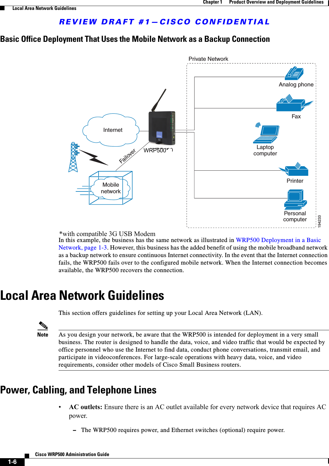
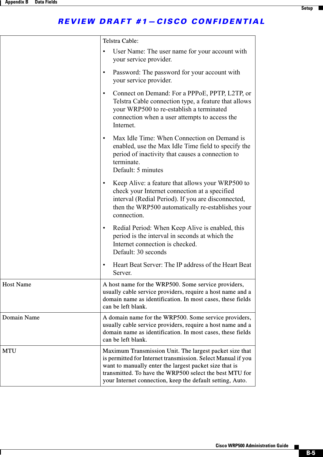
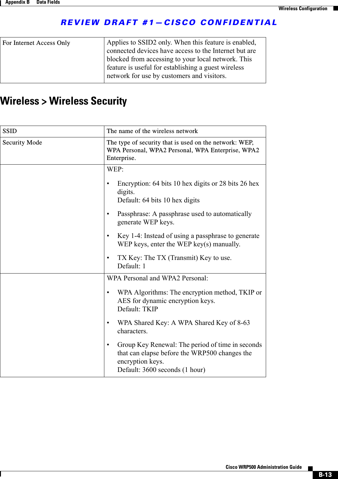
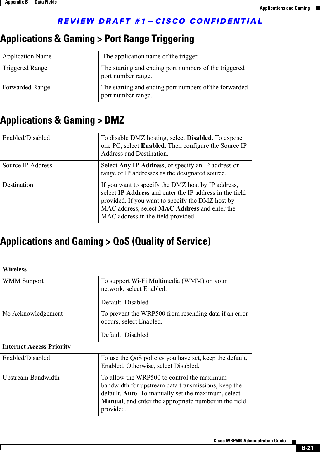
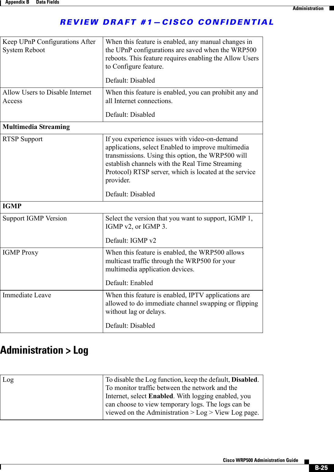
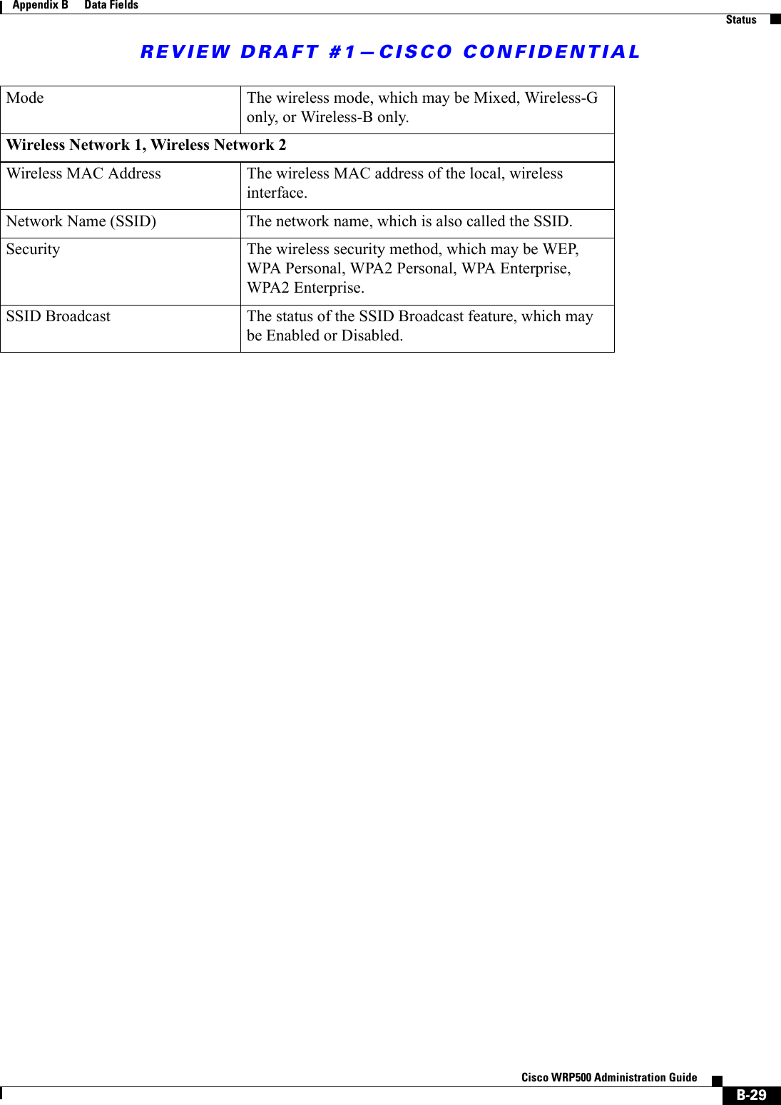
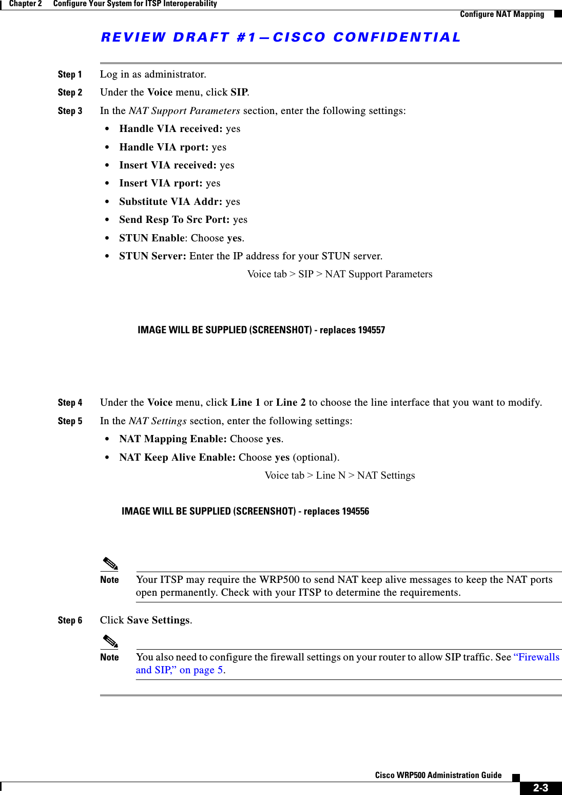
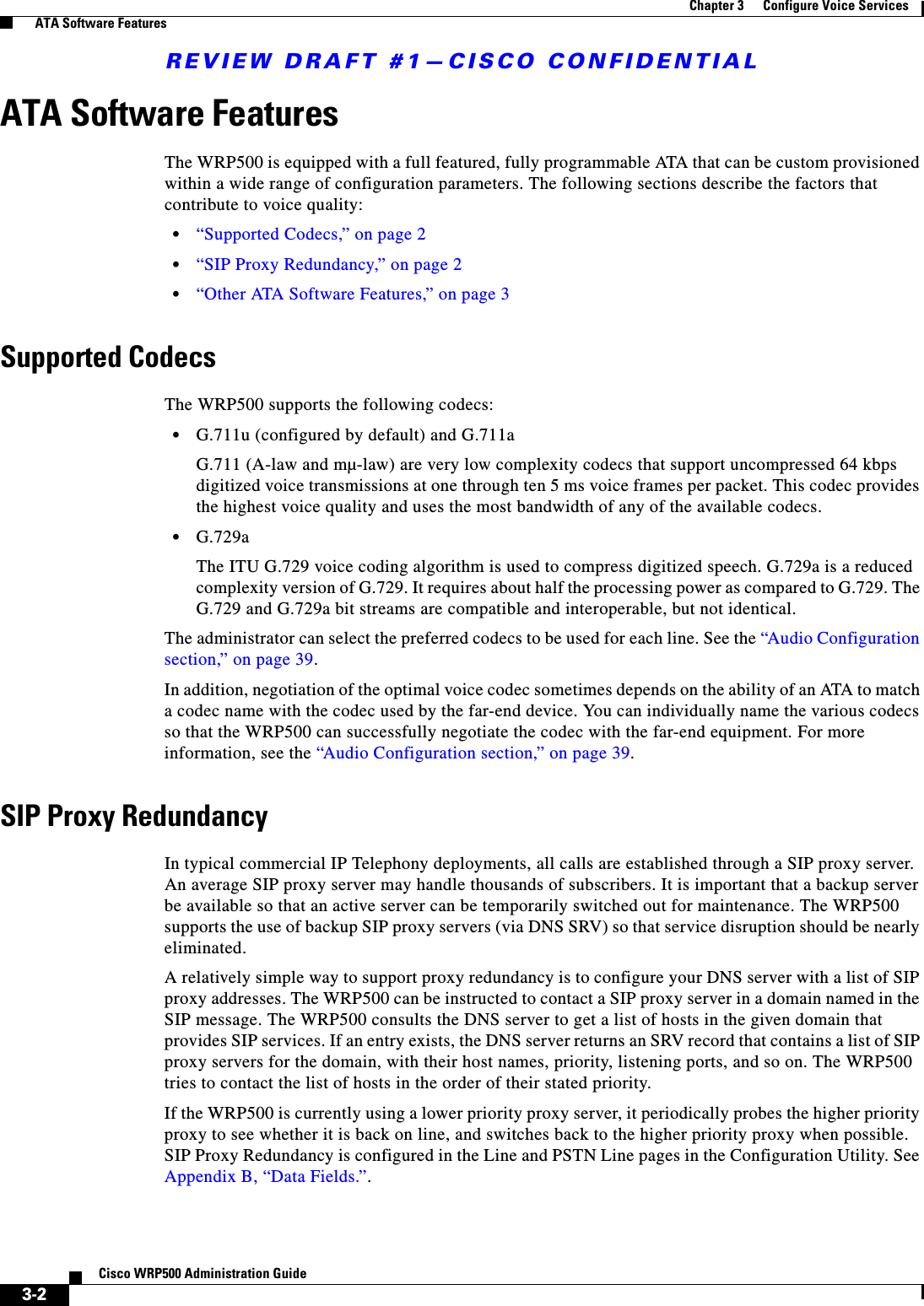
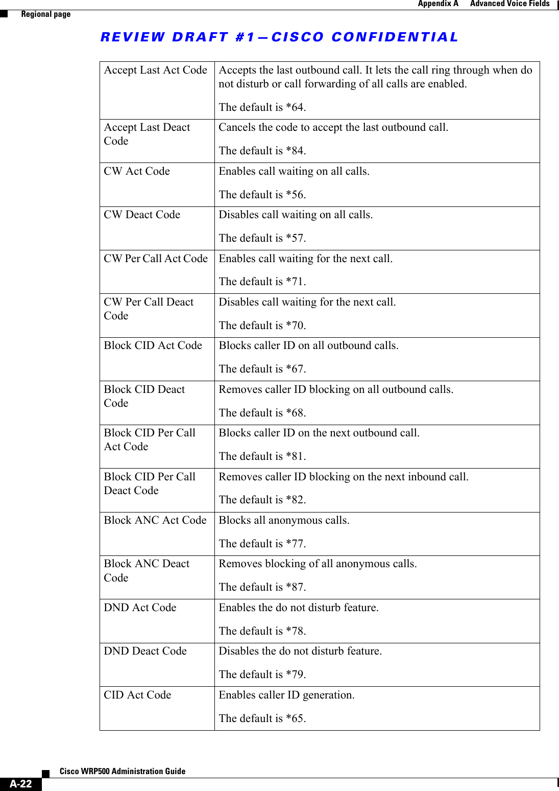
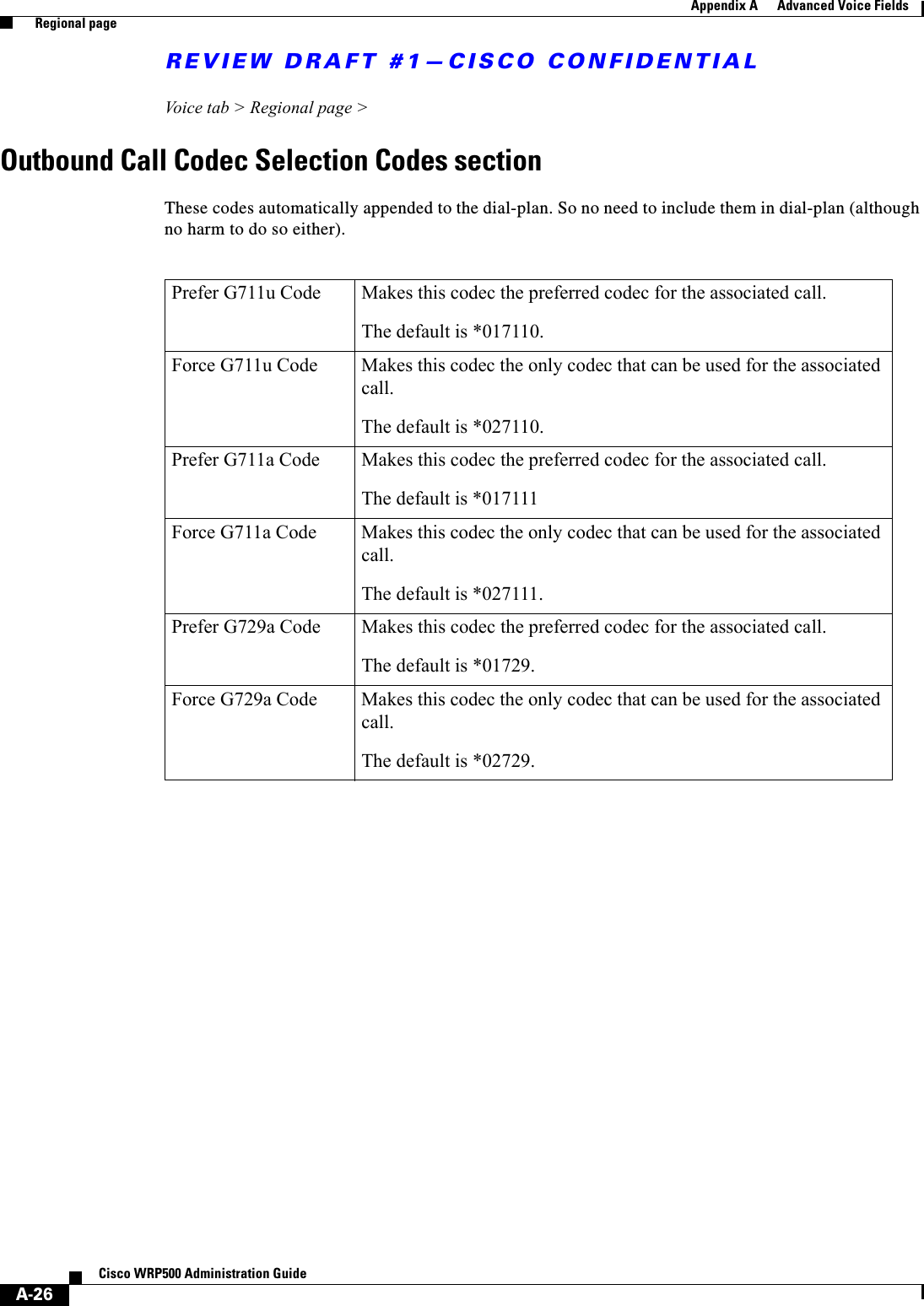
![REVIEW DRAFT #1—CISCO CONFIDENTIAL1-11Cisco WRP500 Administration Guide Chapter 1 Product Overview and Deployment Guidelines Remote ProvisioningFactory reset of voice settings: Use one of the following methods:–Option 1: Log on to the configuration utility, and then click Administration tab > Factory Defaults. Next to Restore Voice Factory Defaults, click Yes. Then click Save Settings to begin the operation.–Option 2: Connect an analog phone to the Phone 1 or Phone 2 port. Press **** to access the Interactive Voice Response menu. After you hear the greeting, press 73738 for factory reset. Listen to the prompts and then press 1 to confirm or * to cancel. After you hear “Option successful,” you can hang up the phone.Remote ProvisioningLike other Cisco Small Business IP Telephony Devices, the WRP500 provides for secure provisioning and remote upgrade. Provisioning is achieved through configuration profiles transferred to the device via TFTP, HTTP, or HTTPS. To configure Provisioning, go to the Provisioning tab in the Configuration Utility. Note For complete details, see the Provisioning Guide at the following URL:www.cisco.com/en/US/docs/voice_ip_comm/csbpvga/ata/provisioning/guide/Cisco_Small_Business_IP_Telephony_Provisioning_Guide.pdfUpgrade URLRemote firmware upgrade is achieved via TFTP or HTTP (firmware upgrades using HTTPS are not supported). Remote upgrades are initiated by causing the WRP500 to request the upgrade firmware image by providing a URL for the WRP500 to retrieve the firmware.Note If the value of the Upgrade Enable parameter in the Provisioning page is No, you cannot upgrade the WRP500 even if the web page indicates otherwise. The syntax of the Upgrade URL is as follows:http://WRP500_ip_address/admin/upgrade?[protocol://][server-name[:port]][/firmware-pathname]Both HTTP and TFTP are supported for the upgrade operation. If no protocol is specified, TFTP is assumed. If no server-name is specified, the host that requests the URL is used as server-name. If no port specified, the default port of the protocol is used. (69 for TFTP or 80 for HTTP)The firmware-pathname is typically the file name of the binary located in a directory on the TFTP or HTTP server. If no firmware-pathname is specified, /spa.bin is assumed, as in the following example: http://192.168.2.217/admin/upgrade?tftp://192.168.2.251/spa.bin](https://usermanual.wiki/Cisco-Systems/WRP501156.User-Manual-1/User-Guide-2516588-Page-17.png)
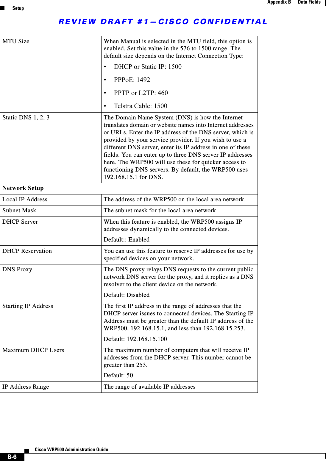
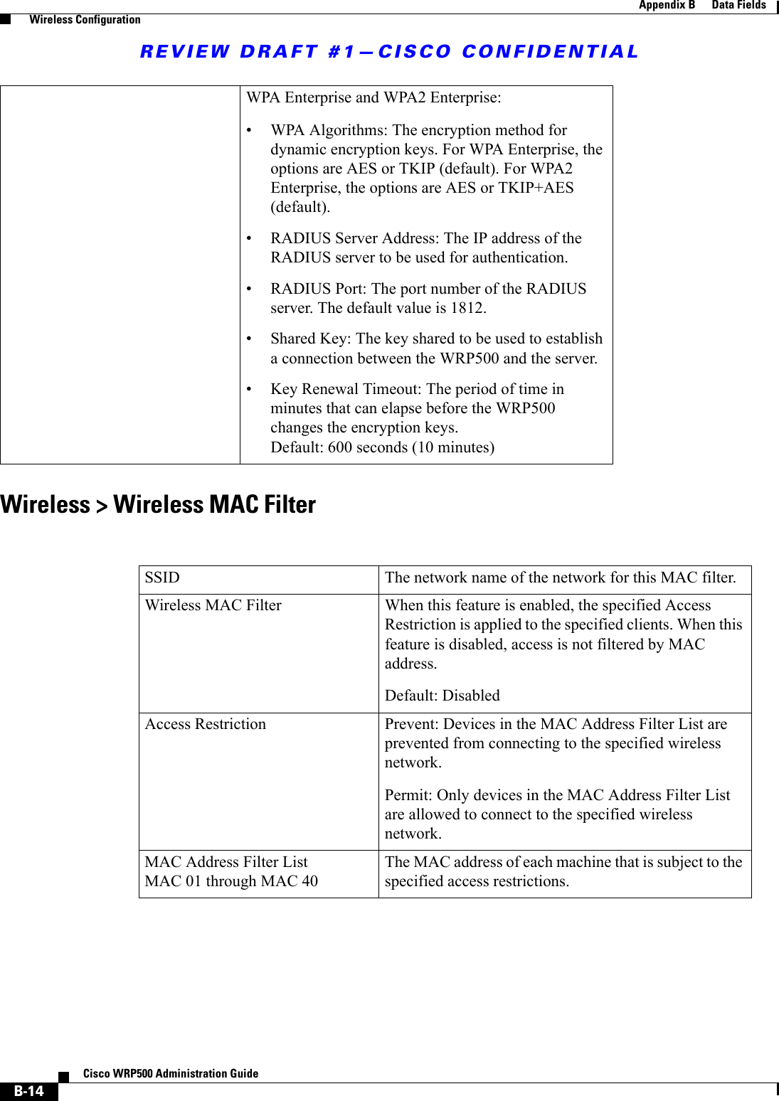
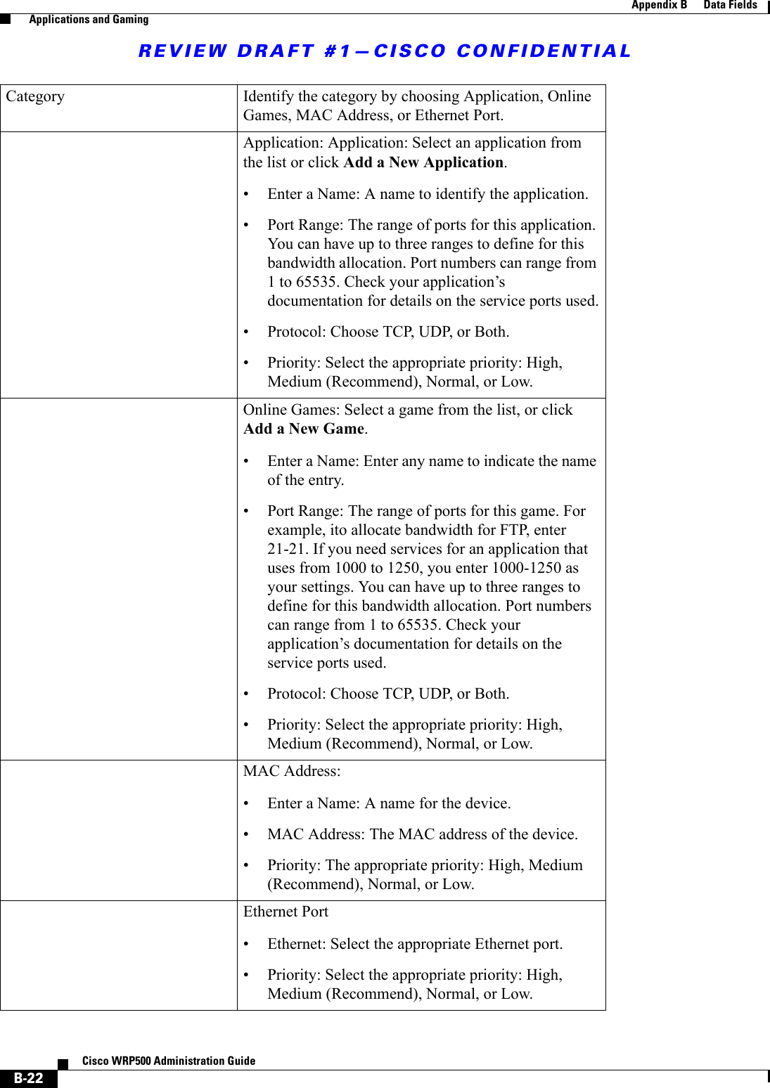
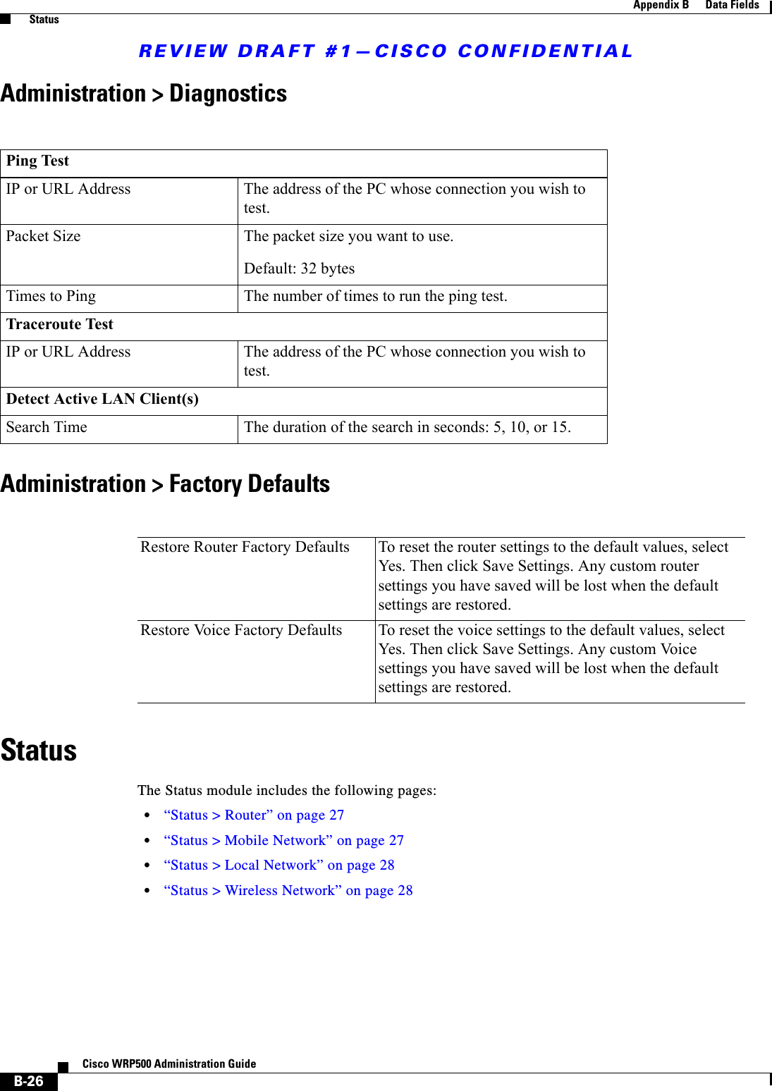
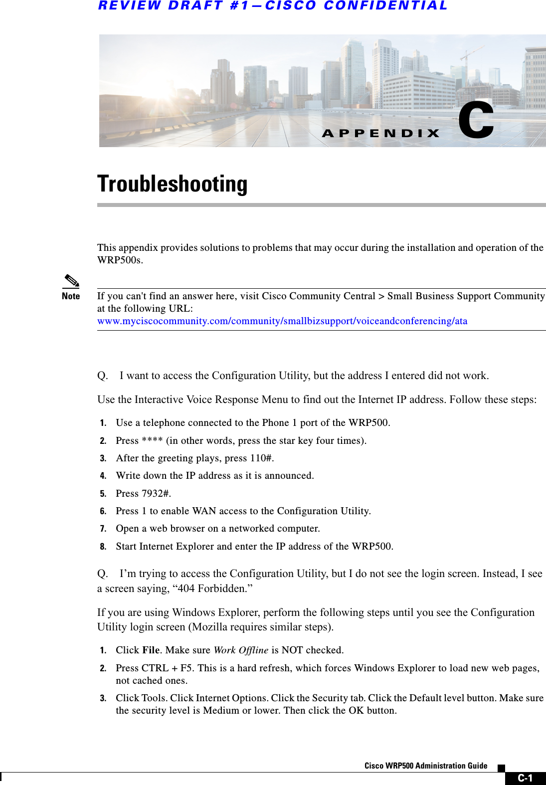
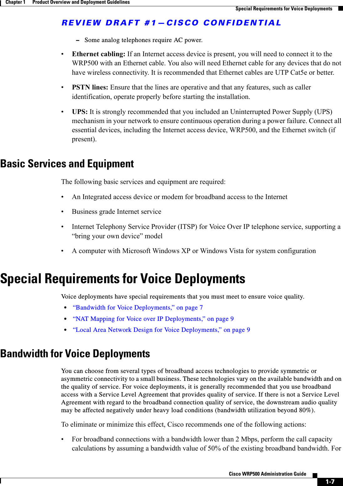
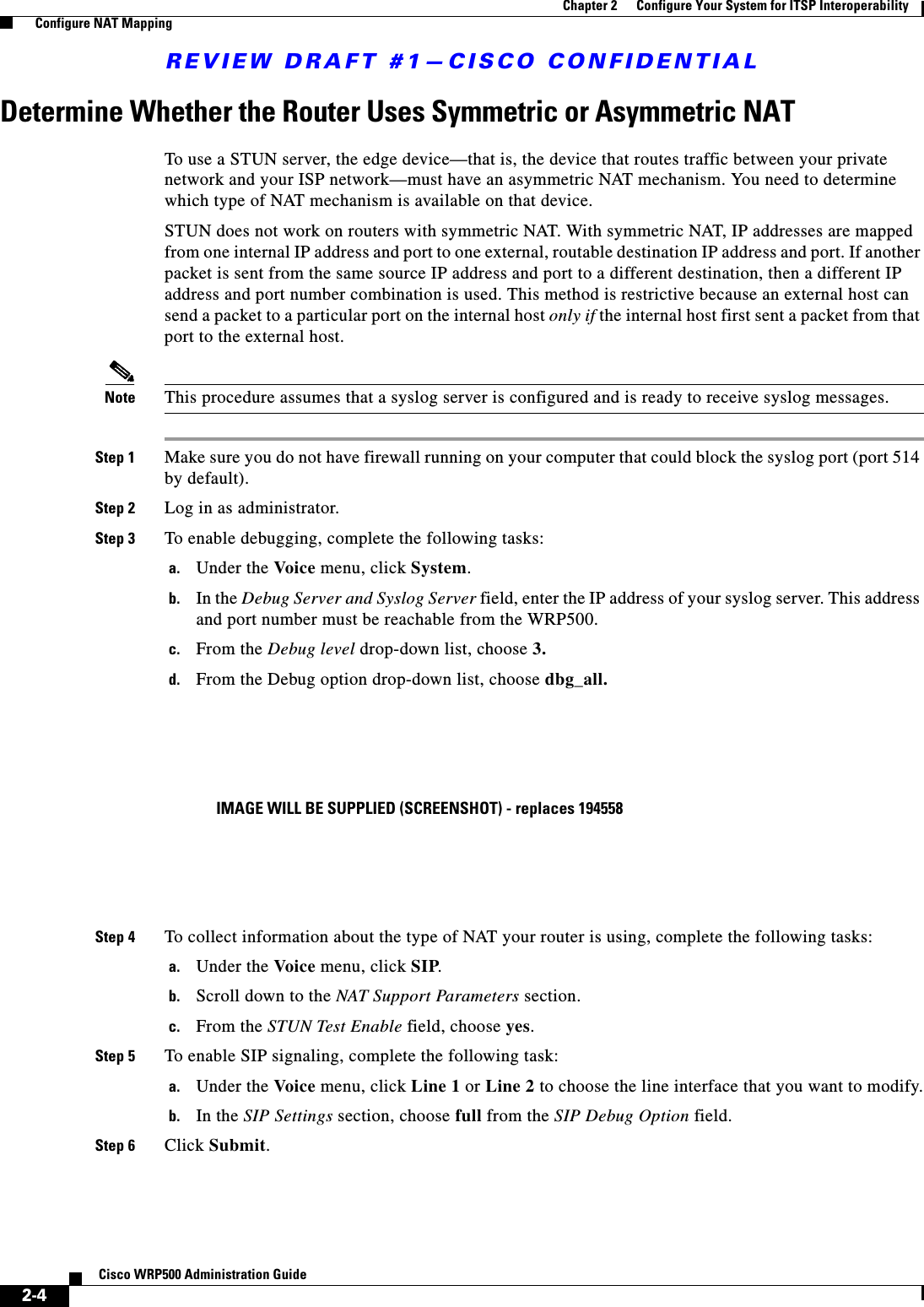
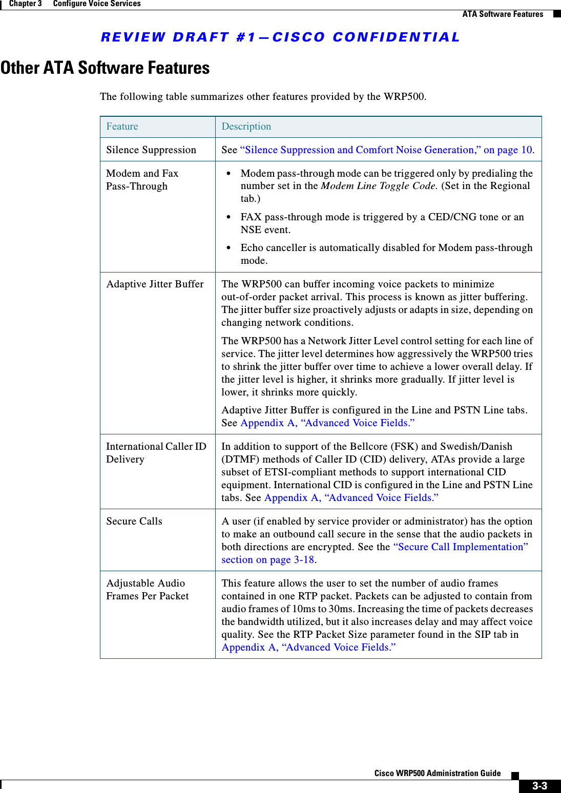
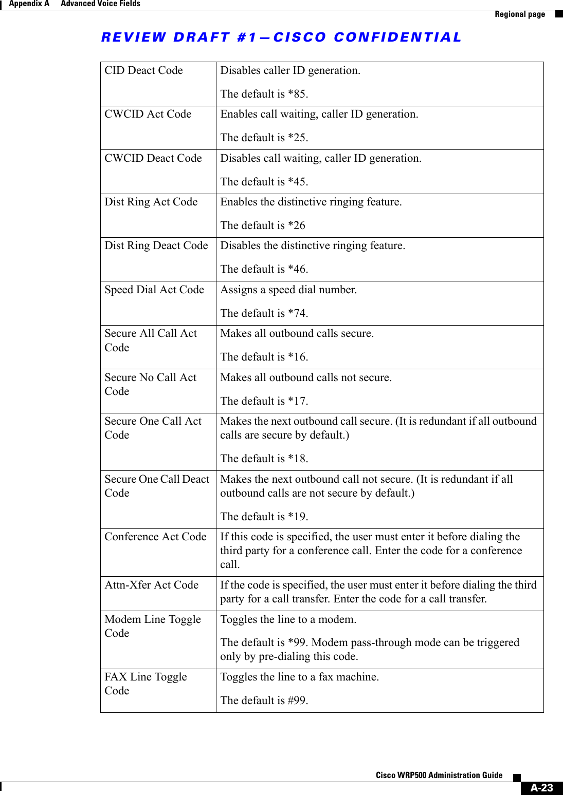
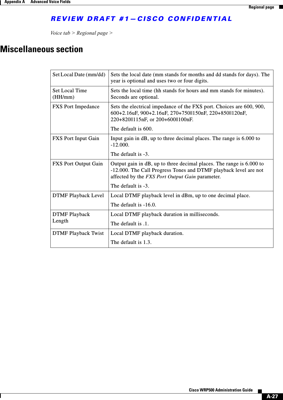
![REVIEW DRAFT #1—CISCO CONFIDENTIAL1-12Cisco WRP500 Administration Guide Chapter 1 Product Overview and Deployment Guidelines Remote ProvisioningResync URLThe WRP500 can be configured to automatically resync its internal configuration state to a remote profile periodically and on power up. The automatic resyncs are controlled by configuring the desired profile URL into the device.The Resync URL lets you force the WRP500 to do a resync to a profile specified in the URL, which can identify either a TFTP, HTTP, or HTTPS server. The syntax of the Resync URL is as follows:http://WRP500_ip_address/admin/resync?[[protocol://][server-name[:port]]/profile-pathname]Note The WRP500 resyncs only when it is idle.If no port is specified, the default port is used (69 for TFTP, 80 for HTTP, and 443 for HTTPS).The profile-path is the path to the new profile with which to resync, for example:http://192.168.2.217/admin/resync?tftp://192.168.2.251/spaconf.xmlReboot URLThe Reboot URL lets you reboot the WRP500. The Reboot URL is as follows:http://WRP500_ip_address/admin/rebootNote The WRP500 reboots only when it is idle.Configuration ProfileBecause the WRP500 has two sets of parameters, one set for data and one set for voice, the requirements vary from the provisioning of other Cisco Small Business IP Telephony Devices. You will have two profiles: one for the data (router) parameters and one for the voice parameters. One benefit of having separate profiles for voice parameters and data parameters is that you can deploy the common data parameters to all of your customer sites and deploy the custom voice parameters to each site individually.•Data (router) parameters: Use the XML format only, as described in the Provisioning Guide. For more information about the data parameters, see Appendix B, “Data Fields.”•Voice parameters: Use the XML format. The binary format is generated by a profile compiler tool available from Cisco. Find the correct SPA Profiler Compiler (SPC) for the firmware that you have installed on your WRP500. For more information about the data parameters, see Appendix A, “.”Note You can download the SPC at the following URL: tools.cisco.com/support/ downloads/go/Redirect.x?mdfid=282414113](https://usermanual.wiki/Cisco-Systems/WRP501156.User-Manual-1/User-Guide-2516588-Page-18.png)

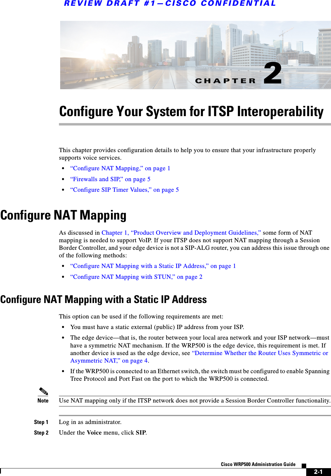
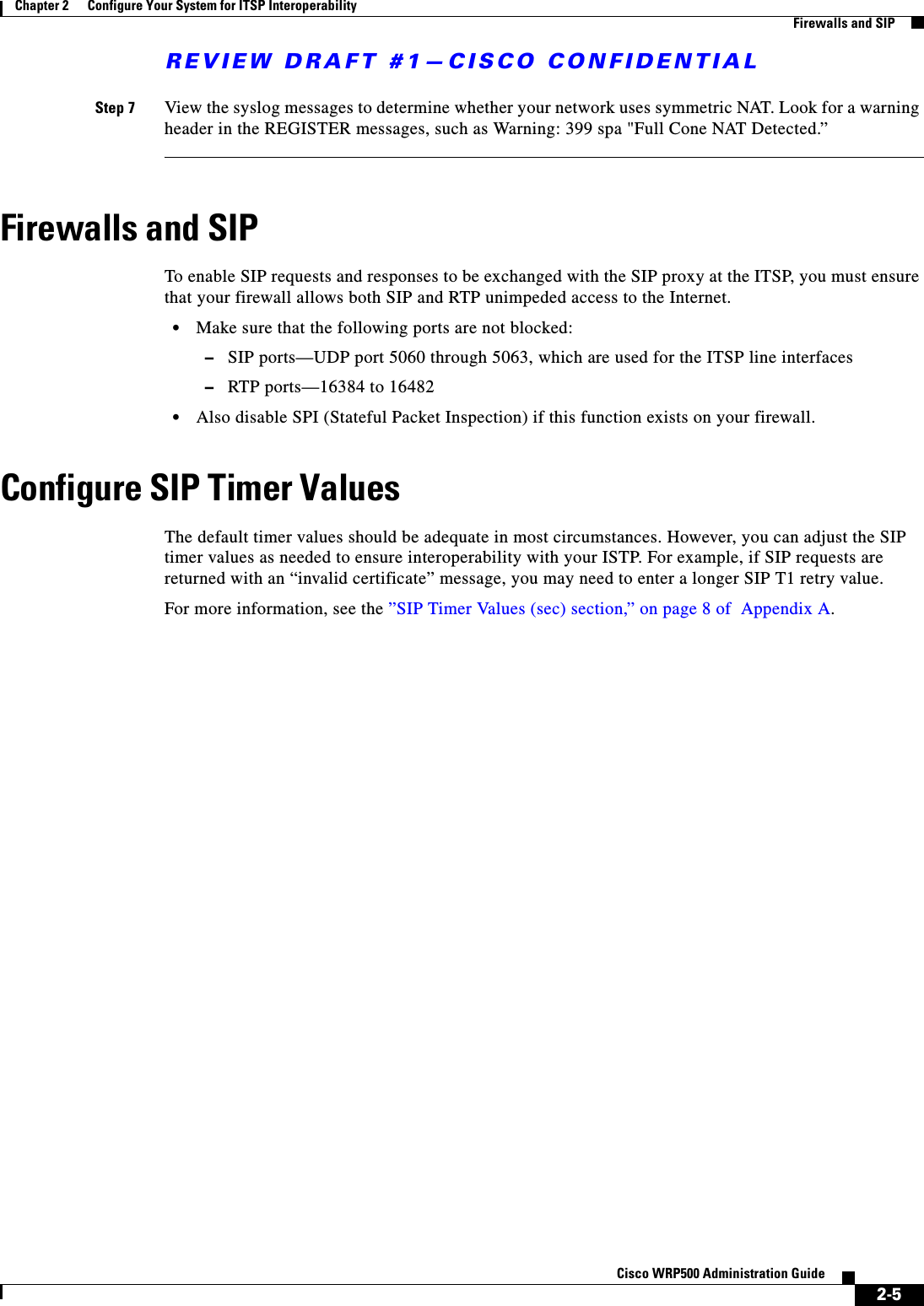

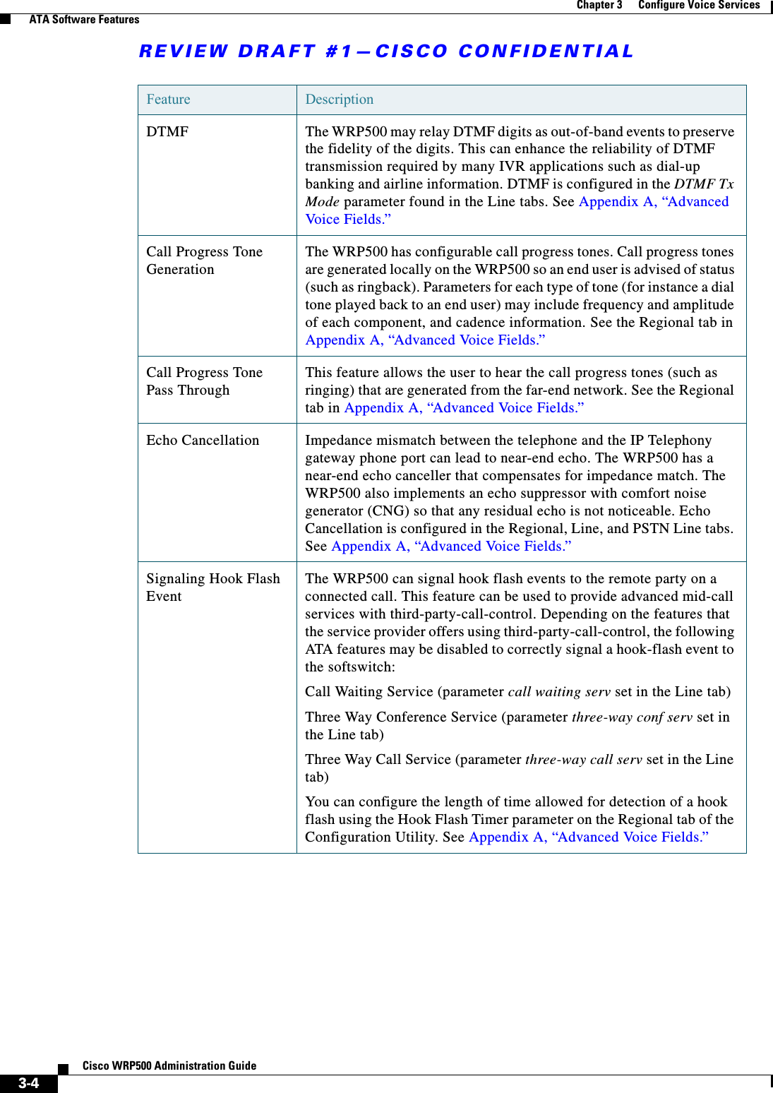
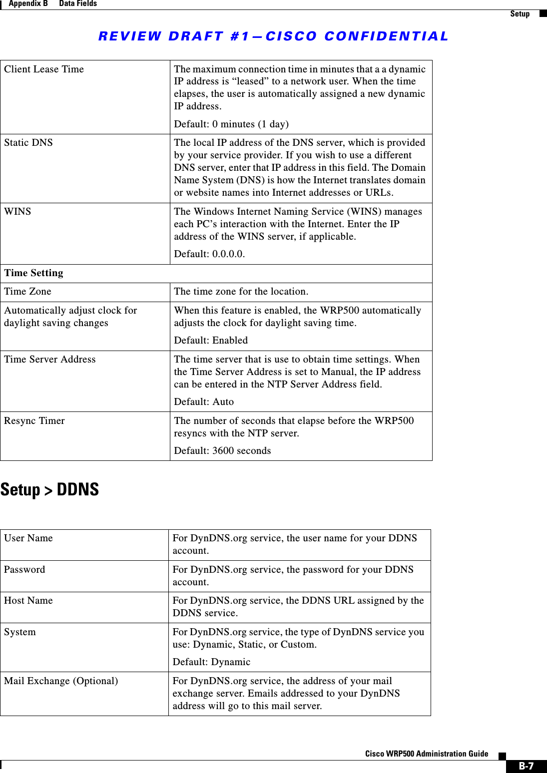
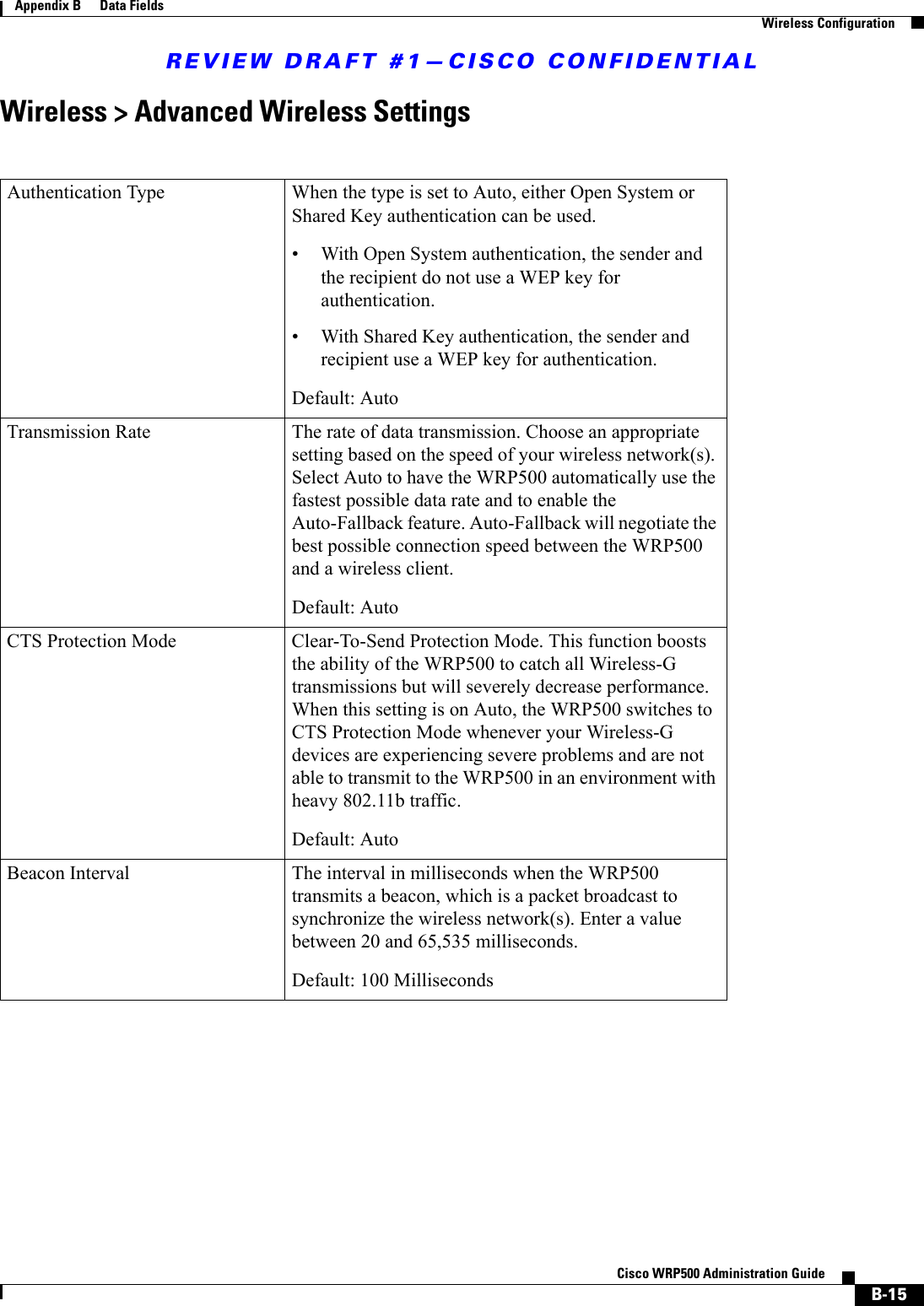
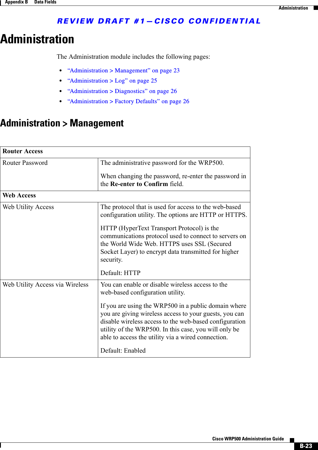
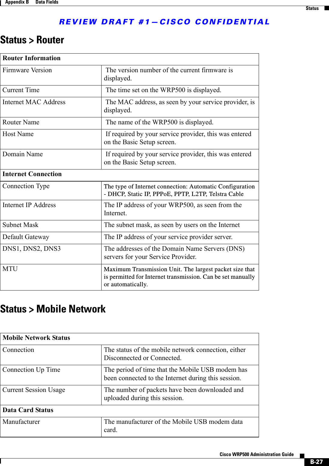
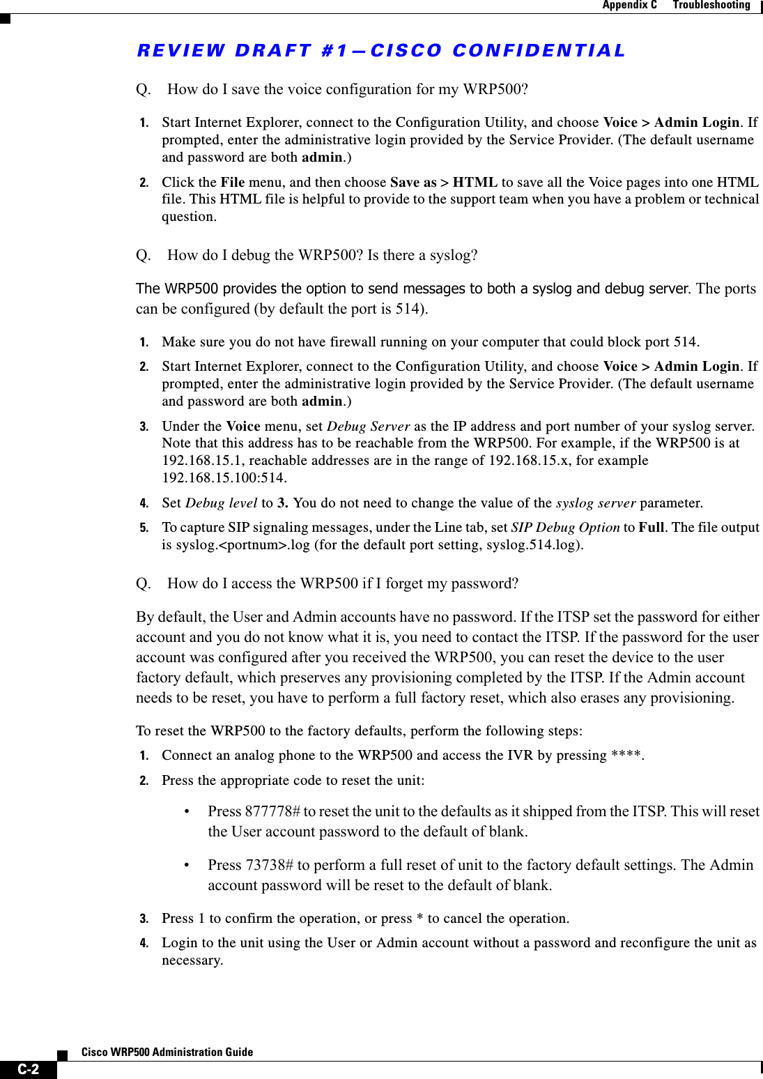
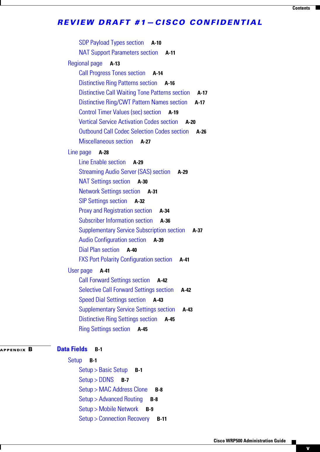
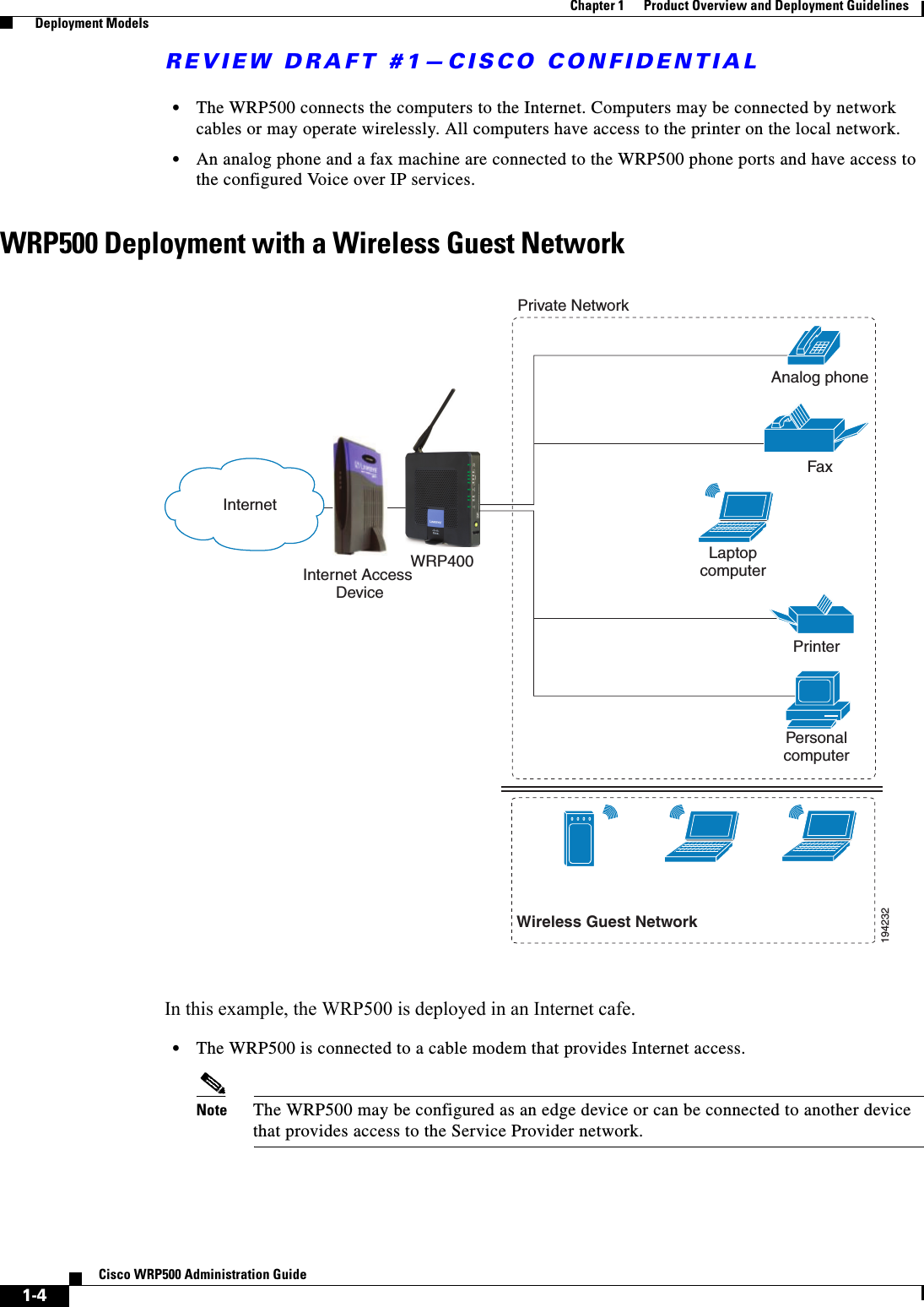
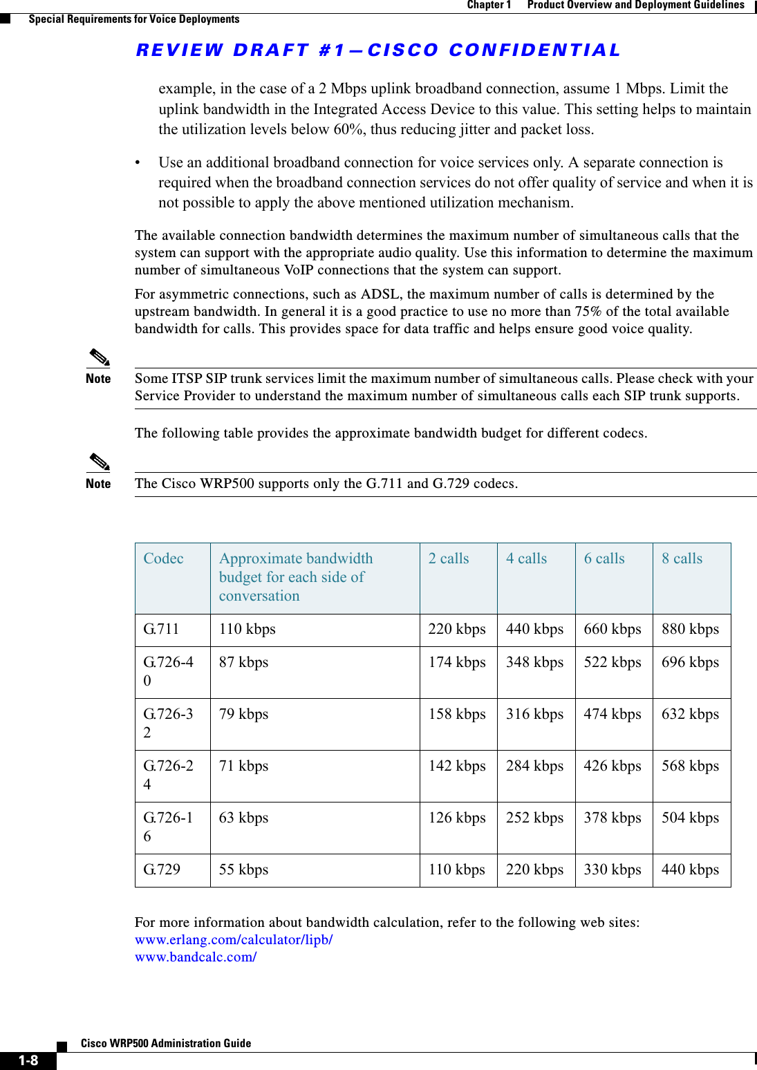
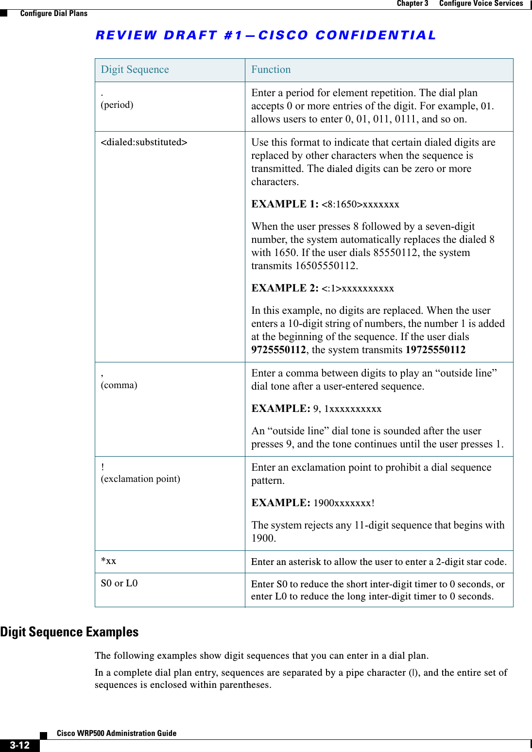
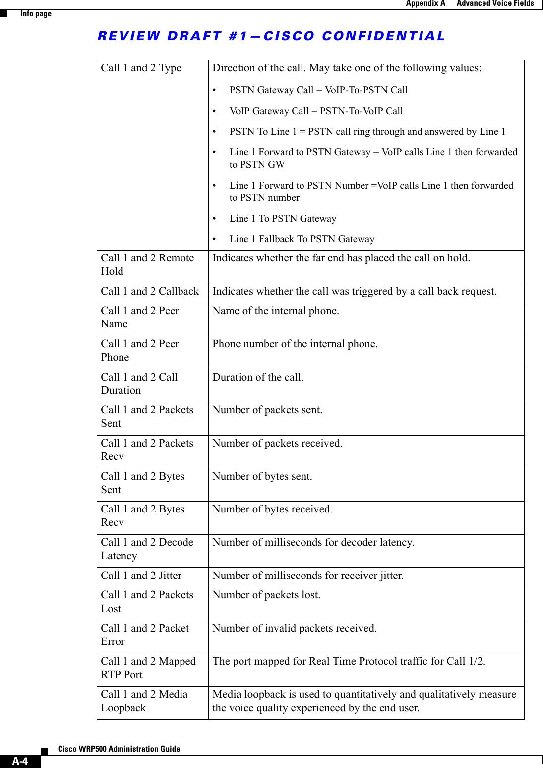
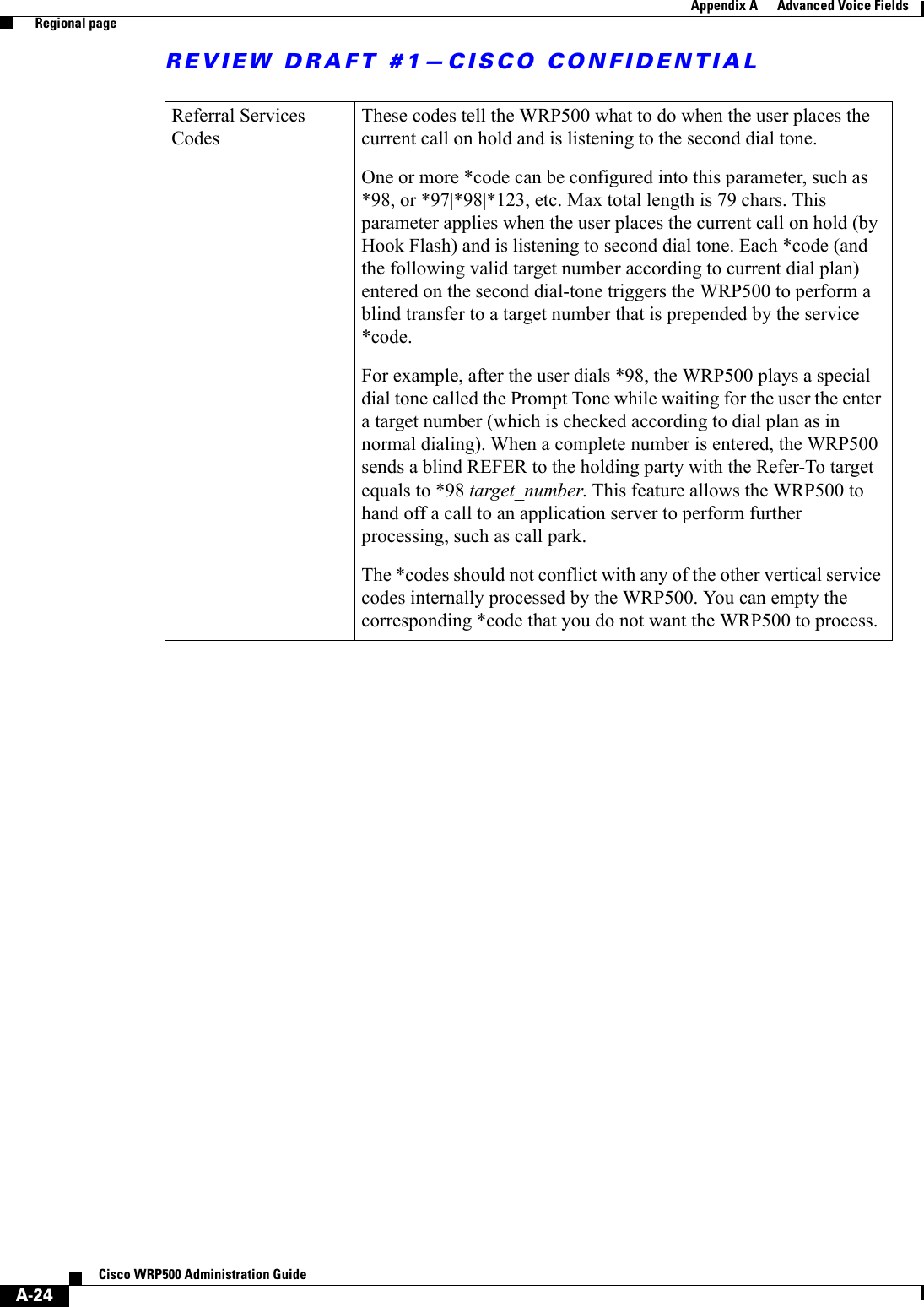
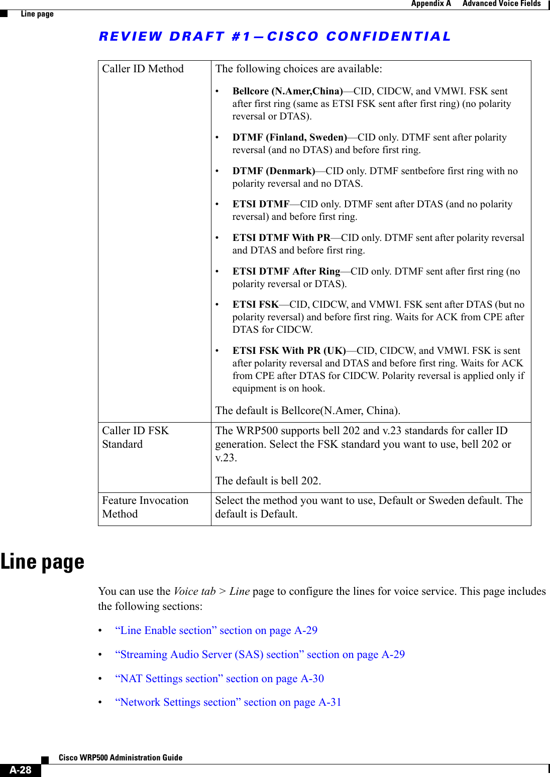
![REVIEW DRAFT #1—CISCO CONFIDENTIAL3-11Cisco WRP500 Administration Guide Chapter 3 Configure Voice Services Configure Dial PlansThis section includes information that you need to understand dial plans, as well as procedures for configuring your own dial plans. This section includes the following topics:•“About Dial Plans,” on page 11•“Edit Dial Plans,” on page 17About Dial PlansThis section provides information to help you understand how dial plans are implemented.Refer to the following topics:•“Digit Sequences,” on page 11•“Digit Sequence Examples,” on page 12•“Acceptance and Transmission the Dialed Digits,” on page 14•“Dial Plan Timer (Off-Hook Timer),” on page 15•“Interdigit Long Timer (Incomplete Entry Timer),” on page 15•“Interdigit Short Timer (Complete Entry Timer),” on page 16Digit SequencesA dial plan contains a series of digit sequences, separated by the | character. The entire collection of sequences is enclosed within parentheses. Each digit sequence within the dial plan consists of a series of elements, which are individually matched to the keys that the user presses. Note White space is ignored, but may be used for readability.Digit Sequence Function0 1 2 3 4 5 6 7 8 9 0 * # Enter any of these characters to represent a key that the user must press on the phone keypad.xEnter x to represent any character on the phone keypad.[sequence] Enter characters within square brackets to create a list of accepted key presses. The user can press any one of the keys in the list.• Numeric range For example, you would enter [2-9] to allow the user to press any one digit from 2 through 9.• Numeric range with other charactersFor example, you would enter [35-8*] to allow the user to press 3, 5, 6, 7, 8, or *.](https://usermanual.wiki/Cisco-Systems/WRP501156.User-Manual-1/User-Guide-2516588-Page-37.png)
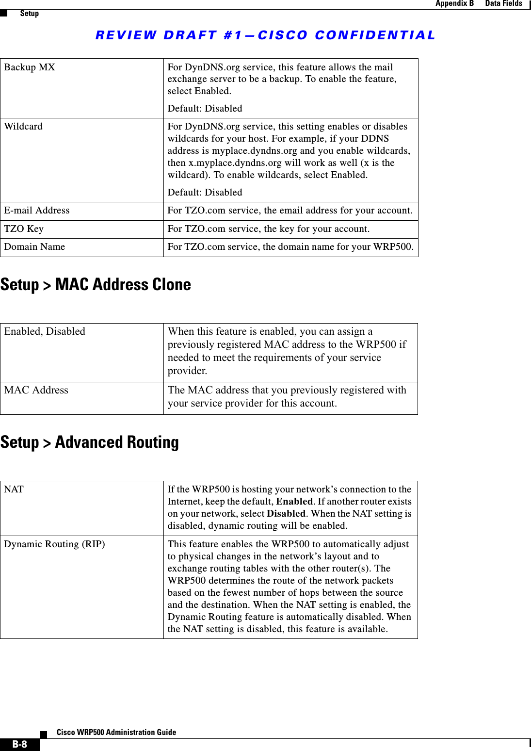
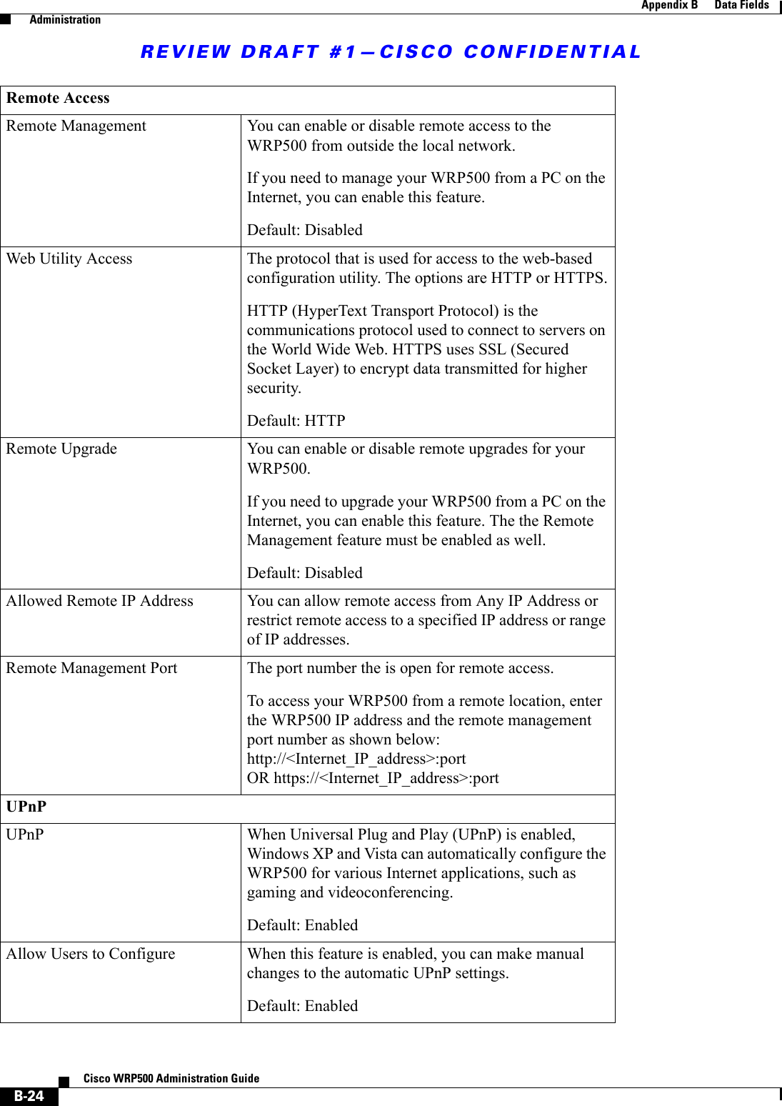
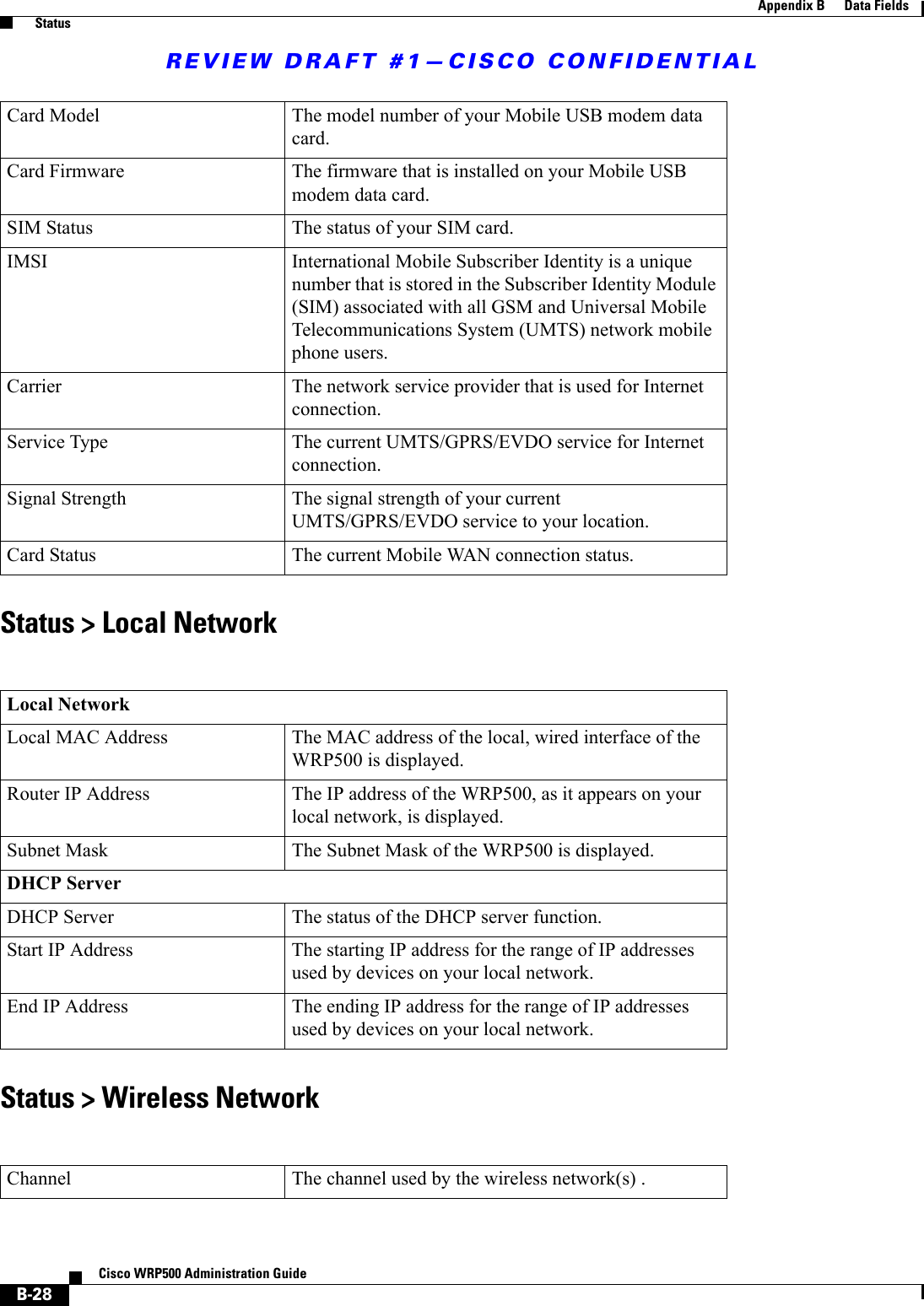
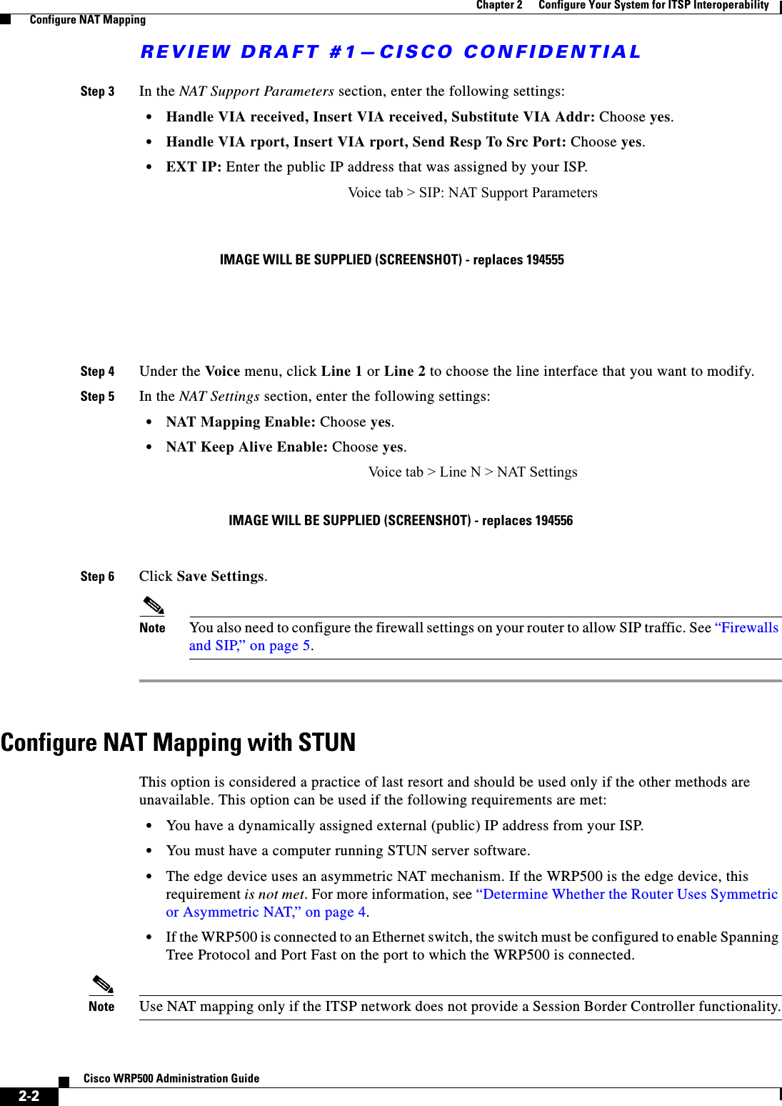
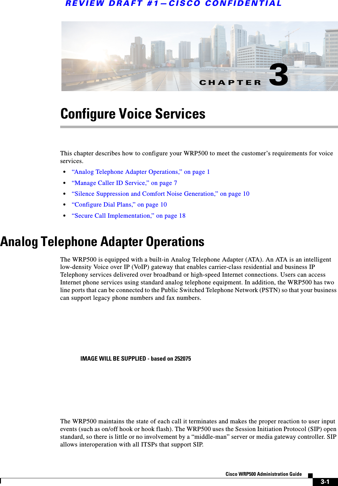
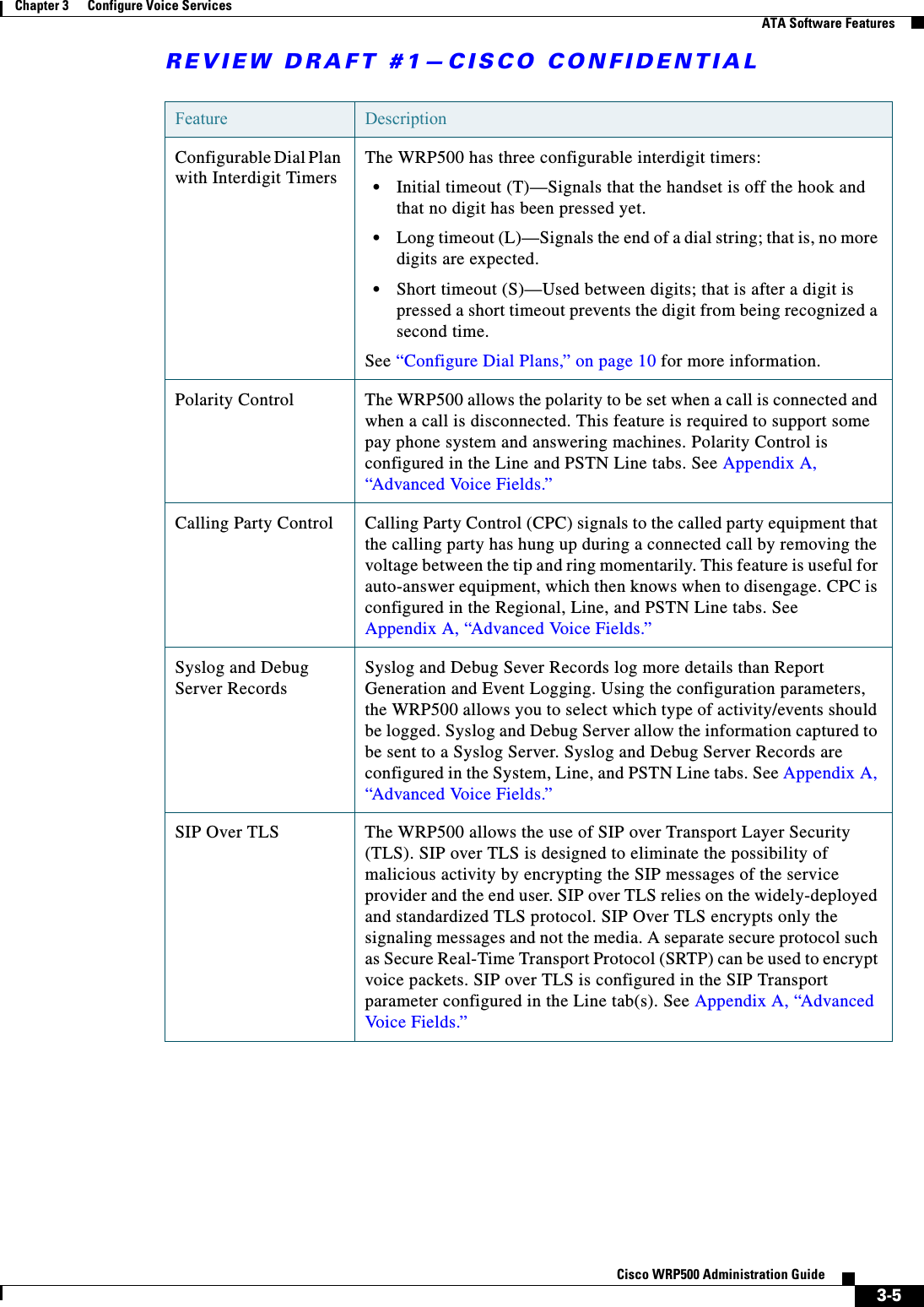
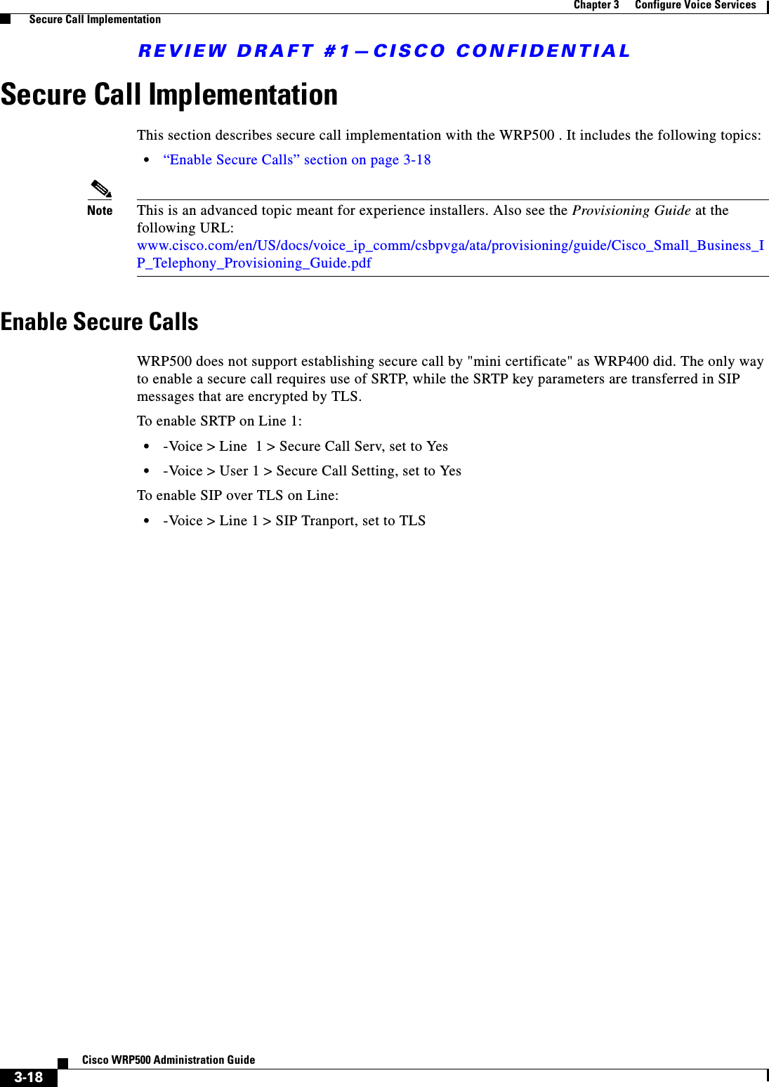
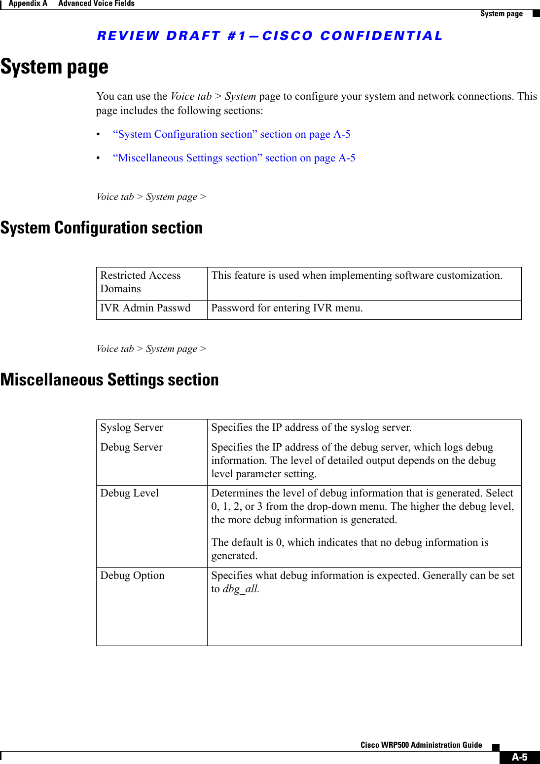
![REVIEW DRAFT #1—CISCO CONFIDENTIAL3-13Cisco WRP500 Administration Guide Chapter 3 Configure Voice Services Configure Dial PlansEXAMPLE: ( [1-8]xx | 9, xxxxxxx | 9, <:1>[2-9]xxxxxxxxx | 8, <:1212>xxxxxxx | 9, 1 [2-9] xxxxxxxxx | 9, 1 900 xxxxxxx ! | 9, 011xxxxxx. | 0 | [49]11 )• Extensions on your systemEXAMPLE: ( [1-8]xx | 9, xxxxxxx | 9, <:1>[2-9]xxxxxxxxx | 8, <:1212>xxxxxxx | 9, 1 [2-9] xxxxxxxxx | 9, 1 900 xxxxxxx ! | 9, 011xxxxxx. | 0 | [49]11 )[1-8]xx Allows a user dial any three-digit number that starts with the digits 1 through 8. If your system uses four-digit extensions, you would instead enter the following string: [1-8]xxx• Local dialing with seven-digit numberEXAMPLE: ( [1-8]xx | 9, xxxxxxx | 9, <:1>[2-9]xxxxxxxxx | 8, <:1212>xxxxxxx | 9, 1 [2-9] xxxxxxxxx | 9, 1 900 xxxxxxx ! | 9, 011xxxxxx. | 0 | [49]111)9, xxxxxxx After a user presses 9, an external dial tone sounds. The user can enter any seven-digit number, as in a local call. • Local dialing with 3-digit area code and a 7-digit local numberEXAMPLE: ( [1-8]xx | 9, xxxxxxx | 9, <:1>[2-9]xxxxxxxxx | 8, <:1212>xxxxxxx | 9, 1 [2-9] xxxxxxxxx | 9, 1 900 xxxxxxx ! | 9, 011xxxxxx. | 0 | [49]11 )9, <:1>[2-9]xxxxxxxxx This example is useful where a local area code is required. After a user presses 9, an external dial tone sounds. The user must enter a 10-digit number that begins with a digit 2 through 9. The system automatically inserts the 1 prefix before transmitting the number to the carrier. • Local dialing with an automatically inserted 3-digit area codeEXAMPLE: ( [1-8]xx | 9, xxxxxxx | 9, <:1>[2-9]xxxxxxxxx | 8, <:1212>xxxxxxx | 9, 1 [2-9] xxxxxxxxx | 9, 1 900 xxxxxxx ! | 9, 011xxxxxx. | 0 | [49]11 )8, <:1212>xxxxxxx This is example is useful where a local area code is required by the carrier but the majority of calls go to one area code. After the user presses 8, an external dial tone sounds. The user can enter any seven-digit number. The system automatically inserts the 1 prefix and the 212 area code before transmitting the number to the carrier.• U.S. long distance dialing EXAMPLE: ( [1-8]xx | 9, xxxxxxx | 9, <:1>[2-9]xxxxxxxxx | 8, <:1212>xxxxxxx | 9, 1 [2-9] xxxxxxxxx | 9, 1 900 xxxxxxx ! | 9, 011xxxxxx. | 0 | [49]11 )9, 1 [2-9] xxxxxxxxx After the user presses 9, an external dial tone sounds. The user can enter any 11-digit number that starts with 1 and is followed by a digit 2 through 9. • Blocked numberEXAMPLE: ( [1-8]xx | 9, xxxxxxx | 9, <:1>[2-9]xxxxxxxxx | 8, <:1212>xxxxxxx | 9, 1 [2-9] xxxxxxxxx | 9, 1 900 xxxxxxx ! | 9, 011xxxxxx. | 0 | [49]11 )9, 1 900 xxxxxxx ! This digit sequence is useful if you want to prevent users from dialing numbers that are associated with high tolls or inappropriate content, such as 1-900 numbers in the U.S.. After the user press 9, an external dial tone sounds. If the user enters an 11-digit number that starts with the digits 1900, the call is rejected.• U.S. international dialing](https://usermanual.wiki/Cisco-Systems/WRP501156.User-Manual-1/User-Guide-2516588-Page-39.png)
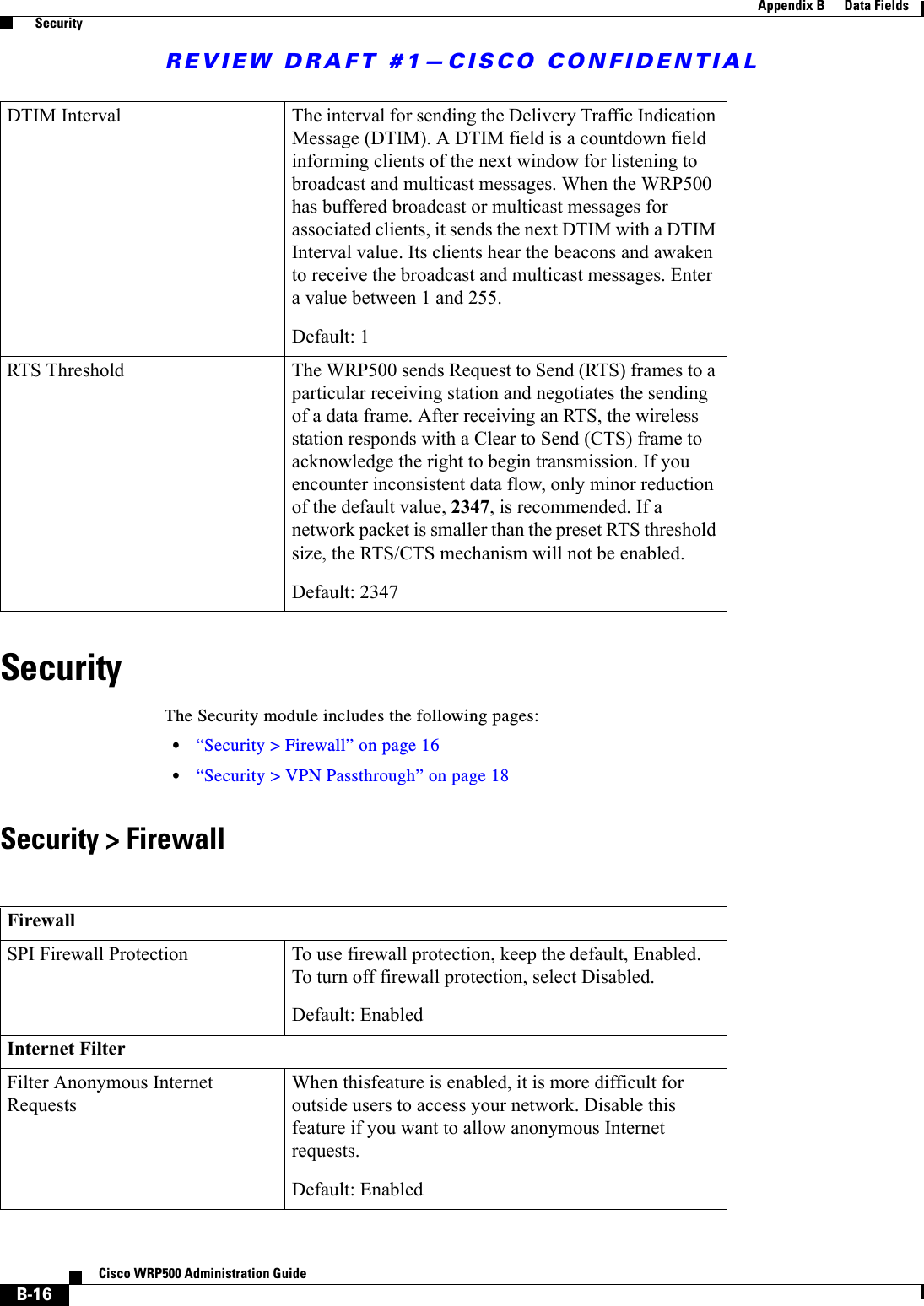
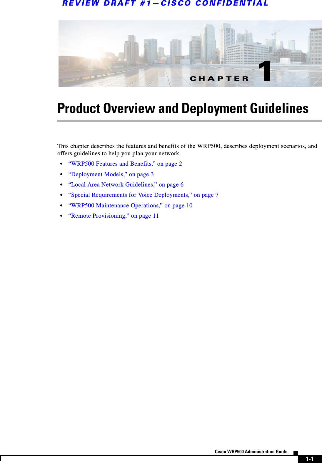
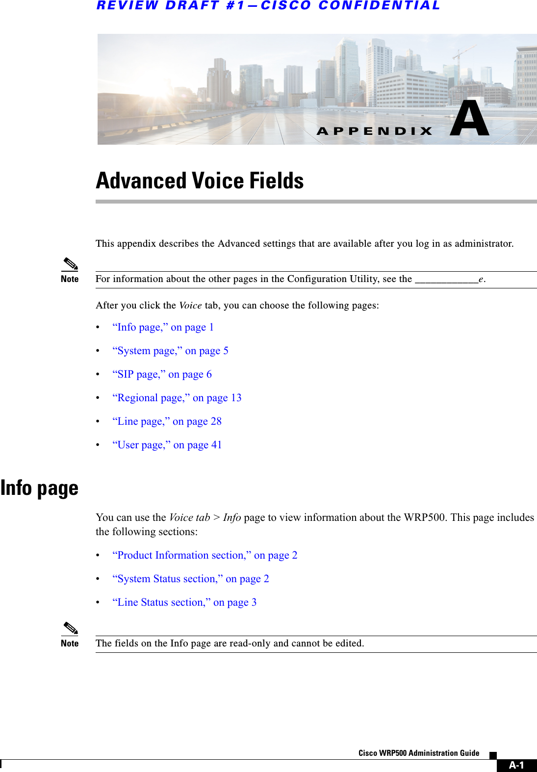
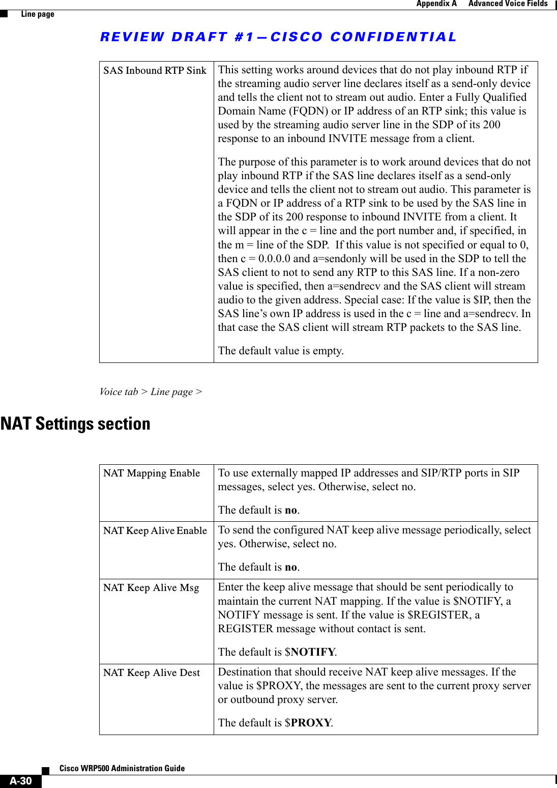
![REVIEW DRAFT #1—CISCO CONFIDENTIAL3-14Cisco WRP500 Administration Guide Chapter 3 Configure Voice Services Configure Dial PlansEXAMPLE: ( [1-8]xx | 9, xxxxxxx | 9, <:1>[2-9]xxxxxxxxx | 8, <:1212>xxxxxxx | 9, 1 [2-9] xxxxxxxxx | 9, 1 900 xxxxxxx ! | 9, 011xxxxxx. | 0 | [49]11 )9, 011xxxxxx. After the user presses 9, an external dial tone sounds. The user can enter any number that starts with 011, as in an international call from the U.S. • Informational numbersEXAMPLE: ( [1-8]xx | 9, xxxxxxx | 9, <:1>[2-9]xxxxxxxxx | 8, <:1212>xxxxxxx | 9, 1 [2-9] xxxxxxxxx | 9, 1 900 xxxxxxx ! | 9, 011xxxxxx. | 0 | [49]11 )0 | [49]11 This example includes two digit sequences, separated by the pipe character. The first sequence allows a user to dial 0 for an operator. The second sequence allows the user to enter 411 for local information or 911 for emergency services. Acceptance and Transmission the Dialed DigitsWhen a user dials a series of digits, each sequence in the dial plan is tested as a possible match. The matching sequences form a set of candidate digit sequences. As more digits are entered by the user, the set of candidates diminishes until only one or none are valid. When a terminating event occurs, the WRP500 either accepts the user-dialed sequence and initiates a call, or else rejects the sequence as invalid. The user hears the reorder (fast busy) tone if the dialed sequence is invalid. The following table explains how terminating events are processed.Terminating Event ProcessingThe dialed digits do not match any sequence in the dial plan. The number is rejected.The dialed digits exactly match one sequence in the dial plan.• If the sequence is allowed by the dial plan, the number is accepted and is transmitted according to the dial plan. • If the sequence is blocked by the dial plan, the number is rejected.A timeout occurs. The number is rejected if the dialed digits are not matched to a digit sequence in the dial plan within the time specified by the applicable interdigit timer.• The Interdigit Long Timer applies when the dialed digits do not match any digit sequence in the dial plan. The default value is 10 seconds.• The Interdigit Short Timer applies when the dialed digits match one or more candidate sequences in the dial plan. The default value is 3 seconds.The user presses the # key or the dial softkey on the phone display.• If the sequence is complete and is allowed by the dial plan, the number is accepted and is transmitted according to the dial plan. • If the sequence is incomplete or is blocked by the dial plan, the number is rejected.](https://usermanual.wiki/Cisco-Systems/WRP501156.User-Manual-1/User-Guide-2516588-Page-40.png)
![REVIEW DRAFT #1—CISCO CONFIDENTIAL3-15Cisco WRP500 Administration Guide Chapter 3 Configure Voice Services Configure Dial PlansDial Plan Timer (Off-Hook Timer)You can think of the Dial Plan Timer as “the off-hook timer.” This timer starts counting when the phone goes off hook. If no digits are dialed within the specified number of seconds, the timer expires and the null entry is evaluated. Unless you have a special dial plan string to allow a null entry, the call is rejected. The default value is 5. Syntax for the Dial Plan TimerSYNTAX: (Ps<:n> | dial plan )•s: The number of seconds; if no number is entered after P, the default timer of 5 seconds applies.•n: (optional): The number to transmit automatically when the timer expires; you can enter an extension number or a DID number. No wildcard characters are allowed because the number will be transmitted as shown. If you omit the number substitution, <:n>, then the user hears a reorder (fast busy) tone after the specified number of seconds.Examples for the Dial Plan Timer• Allow more time for users to start dialing after taking a phone off hook.EXAMPLE: (P9 | (9,8<:1408>[2-9]xxxxxx | 9,8,1[2-9]xxxxxxxxx | 9,8,011xx. | 9,8,xx.|[1-8]xx)P9 After taking a phone off hook, a user has 9 seconds to begin dialing. If no digits are pressed within 9 seconds, the user hears a reorder (fast busy) tone. By setting a longer timer, you allow more time for users to enter the digits.• Create a hotline for all sequences on the System Dial PlanEXAMPLE: (P9<:23> | (9,8<:1408>[2-9]xxxxxx | 9,8,1[2-9]xxxxxxxxx | 9,8,011xx. | 9,8,xx.|[1-8]xx)P9<:23> After taking the phone off hook, a user has 9 seconds to begin dialing. If no digits are pressed within 9 seconds, the call is transmitted automatically to extension 23.• Create a hotline on a line button for an extensionEXAMPLE: ( P0 <:1000>)With the timer set to 0 seconds, the call is transmitted automatically to the specified extension when the phone goes off hook. Enter this sequence in the Phone Dial Plan for Ext 2 or higher on a client station. Interdigit Long Timer (Incomplete Entry Timer)You can think of this timer as the “incomplete entry” timer. This timer measures the interval between dialed digits. It applies as long as the dialed digits do not match any digit sequences in the dial plan. Unless the user enters another digit within the specified number of seconds, the entry is evaluated as incomplete, and the call is rejected. The default value is 10 seconds.](https://usermanual.wiki/Cisco-Systems/WRP501156.User-Manual-1/User-Guide-2516588-Page-41.png)
![REVIEW DRAFT #1—CISCO CONFIDENTIAL3-16Cisco WRP500 Administration Guide Chapter 3 Configure Voice Services Configure Dial PlansNote This section explains how to edit a timer as part of a dial plan. Alternatively, you can modify the Control Timer that controls the default interdigit timers for all calls. See “Reset the Control Timers,” on page 17.Syntax for the Interdigit Long TimerSYNTAX: L:s, ( dial plan )•s: The number of seconds; if no number is entered after L:, the default timer of 5 seconds applies.• Note that the timer sequence appears to the left of the initial parenthesis for the dial plan.Example for the Interdigit Long TimerEXAMPLE: L:15, (9,8<:1408>[2-9]xxxxxx | 9,8,1[2-9]xxxxxxxxx | 9,8,011xx. | 9,8,xx.|[1-8]xx)L:15, This dial plan allows the user to pause for up to 15 seconds between digits before the Interdigit Long Timer expires. This setting is especially helpful to users such as sales people, who are reading the numbers from business cards and other printed materials while dialing.Interdigit Short Timer (Complete Entry Timer)You can think of this timer as the “complete entry” timer. This timer measures the interval between dialed digits. It applies when the dialed digits match at least one digit sequence in the dial plan. Unless the user enters another digit within the specified number of seconds, the entry is evaluated. If it is valid, the call proceeds. If it is invalid, the call is rejected. The default value is 3 seconds. Syntax for the Interdigit Short Timer•SYNTAX 1: S:s, ( dial plan )Use this syntax to apply the new setting to the entire dial plan within the parentheses.•SYNTAX 2: sequence SsUse this syntax to apply the new setting to a particular dialing sequence.s: The number of seconds; if no number is entered after S, the default timer of 5 seconds applies.Examples for the Interdigit Short Timer• Set the timer for the entire dial plan.EXAMPLE: S:6, (9,8<:1408>[2-9]xxxxxx | 9,8,1[2-9]xxxxxxxxx | 9,8,011xx. | 9,8,xx.|[1-8]xx)S:6, While entering a number with the phone off hook, a user can pause for up to 15 seconds between digits before the Interdigit Short Timer expires. This setting is especially helpful to users such as sales people, who are reading the numbers from business cards and other printed materials while dialing.• Set an instant timer for a particular sequence within the dial plan.EXAMPLE: (9,8<:1408>[2-9]xxxxxx | 9,8,1[2-9]xxxxxxxxxS0 | 9,8,011xx. | 9,8,xx.|[1-8]xx)](https://usermanual.wiki/Cisco-Systems/WRP501156.User-Manual-1/User-Guide-2516588-Page-42.png)
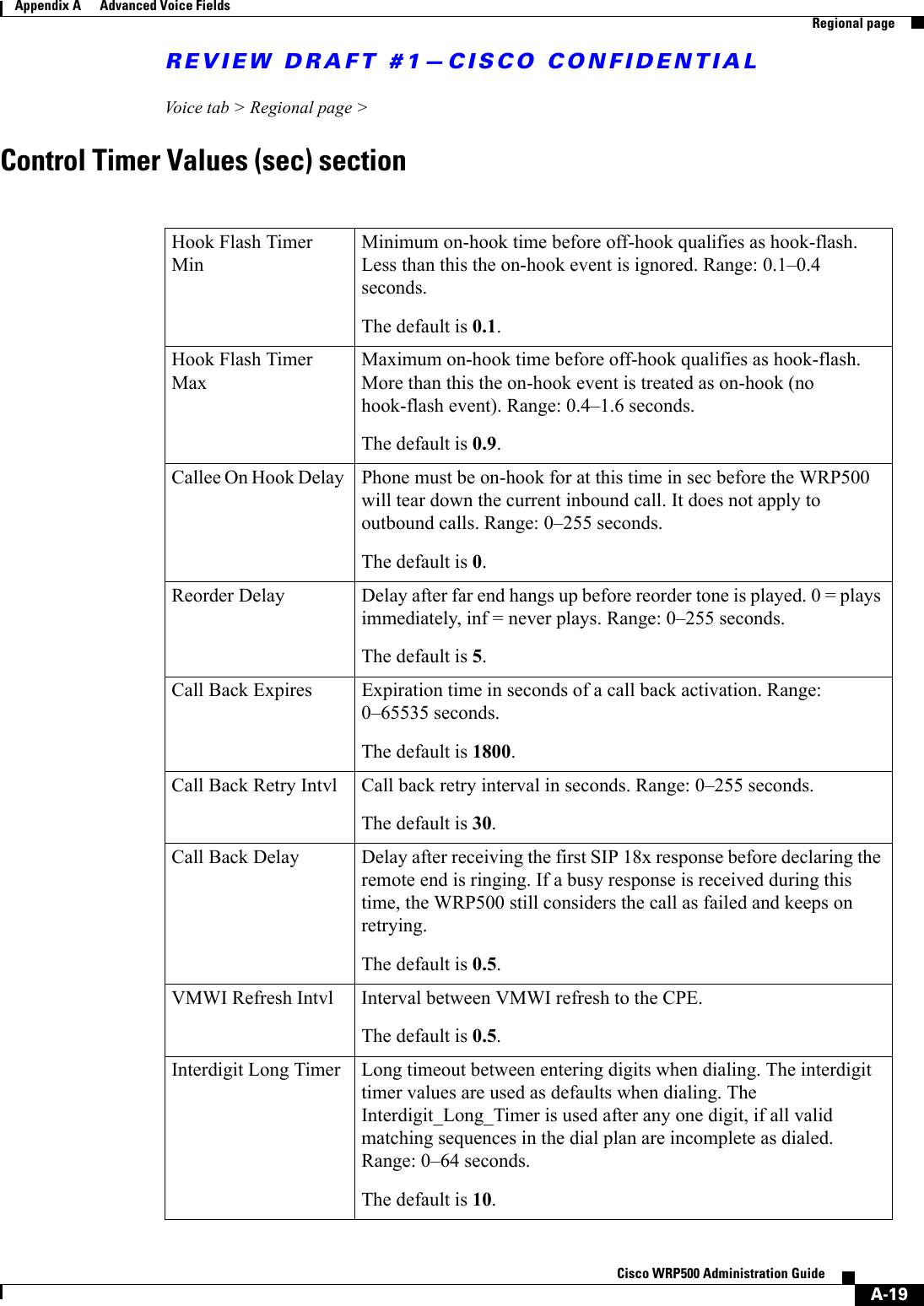
![REVIEW DRAFT #1—CISCO CONFIDENTIAL3-17Cisco WRP500 Administration Guide Chapter 3 Configure Voice Services Configure Dial Plans9,8,1[2-9]xxxxxxxxxS0 With the timer set to 0, the call is transmitted automatically when the user dials the final digit in the sequence.Edit Dial PlansYou can edit dial plans and can modify the control timers.Enter the Line Interface Dial PlanThis dial plan is used to strip steering digits from a dialed number before it is transmitted out to the carrier.Step 1 Start Internet Explorer, connect to the Configuration Utility, choose Voice > Admin Login. If prompted, enter the administrative login provided by the Service Provider. (The default username and password are both admin.)rovided by your Service Provider. Step 2 Under the Voice menu, click Line 1 or Line 2, depending on the line interface that you want to configure.Step 3 Scroll down to the Dial Plan section.Step 4 Enter the digit sequences in the Dial Plan field. For more information, see “About Dial Plans,” on page 11.Step 5 Click Submit.Reset the Control TimersYou can use the following procedure to reset the default timer settings for all calls. Note If you need to edit a timer setting only for a particular digit sequence or type of call, you can edit the dial plan. See “About Dial Plans,” on page 11.Step 1 Start Internet Explorer, connect to the Configuration Utility, choose Voice > Admin Login. If prompted, enter the administrative login provided by the Service Provider. (The default username and password are both admin.)rovided by your Service Provider. Step 2 Under the Voice menu, click Regional.Step 3 Scroll down to the Control Timer Values section.Step 4 Enter the desired values in the Interdigit Long Timer field and the Interdigit Short Timer field. Refer to the definitions at the beginning of this section.](https://usermanual.wiki/Cisco-Systems/WRP501156.User-Manual-1/User-Guide-2516588-Page-43.png)
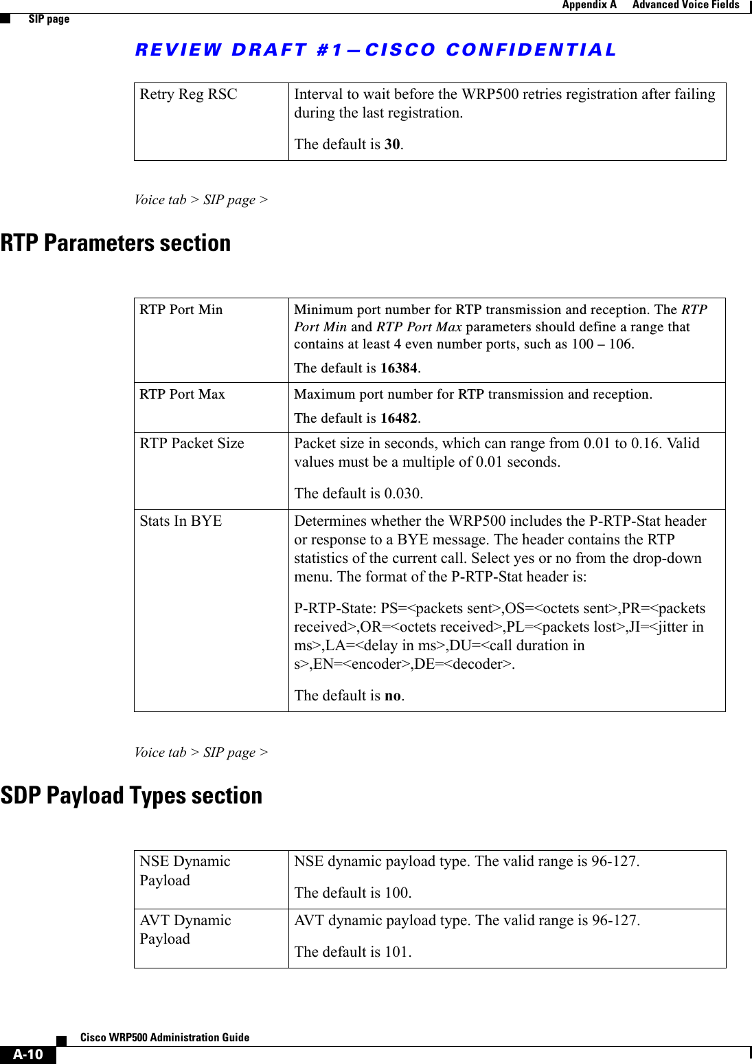
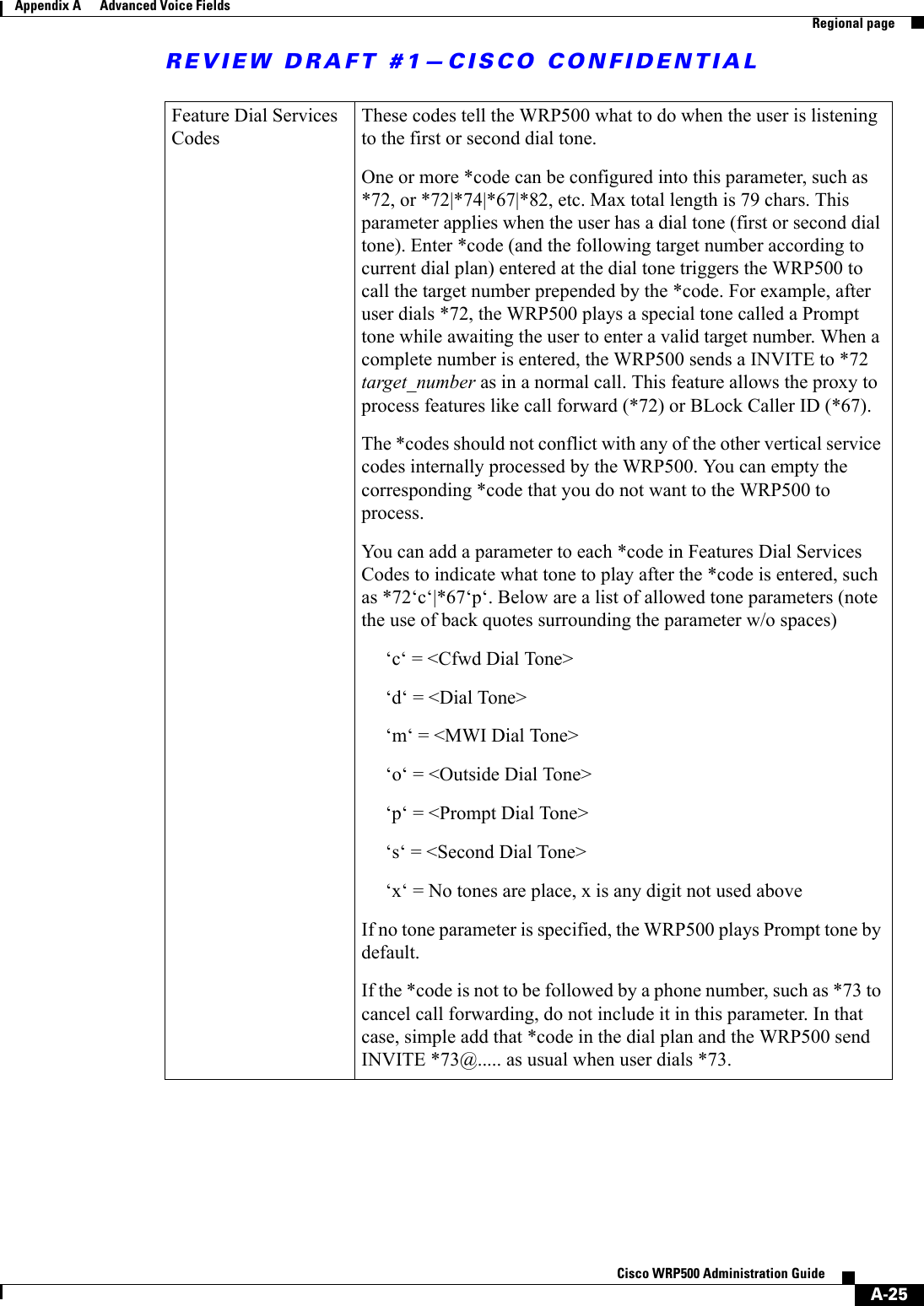
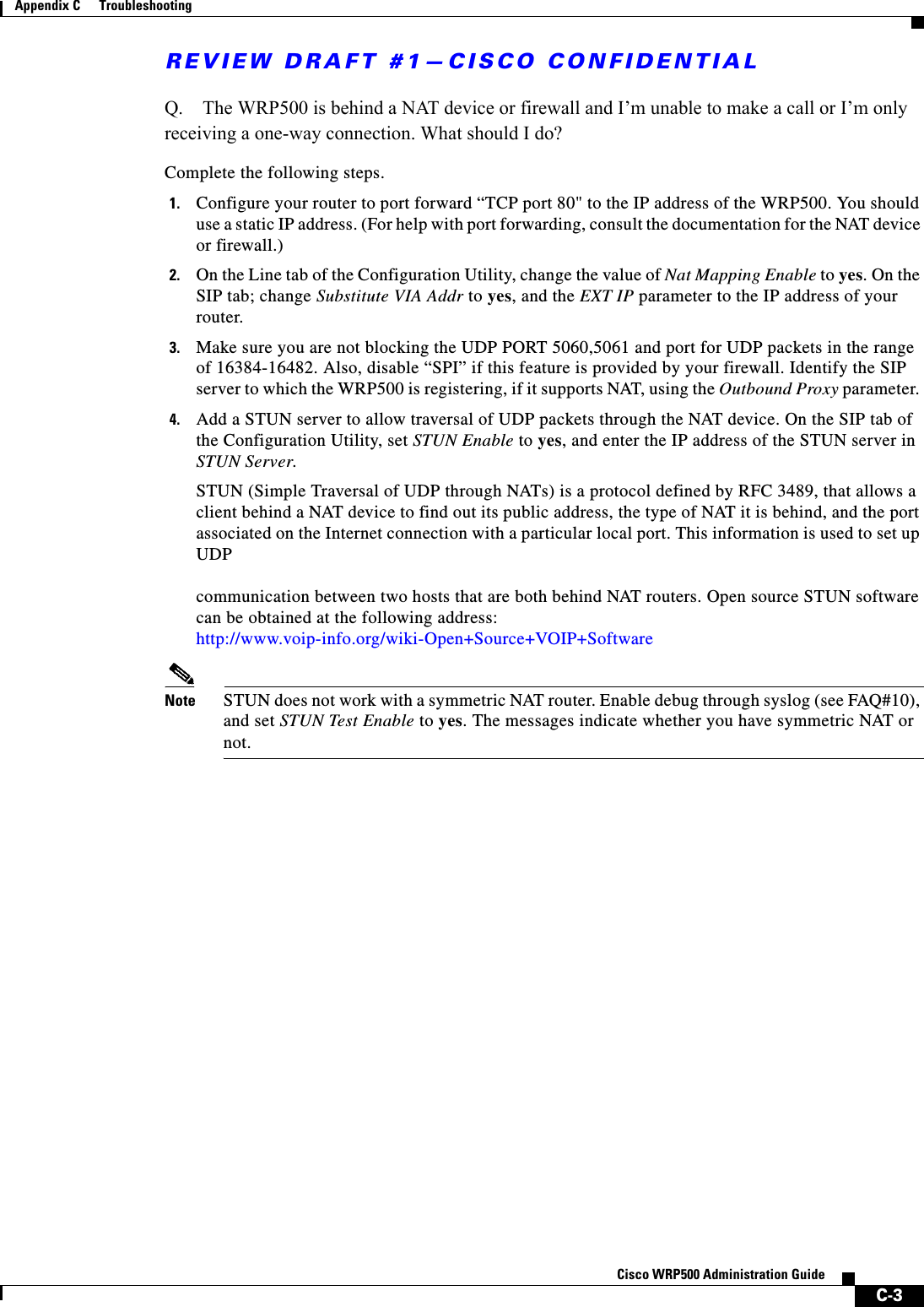
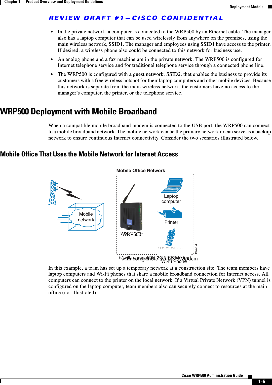
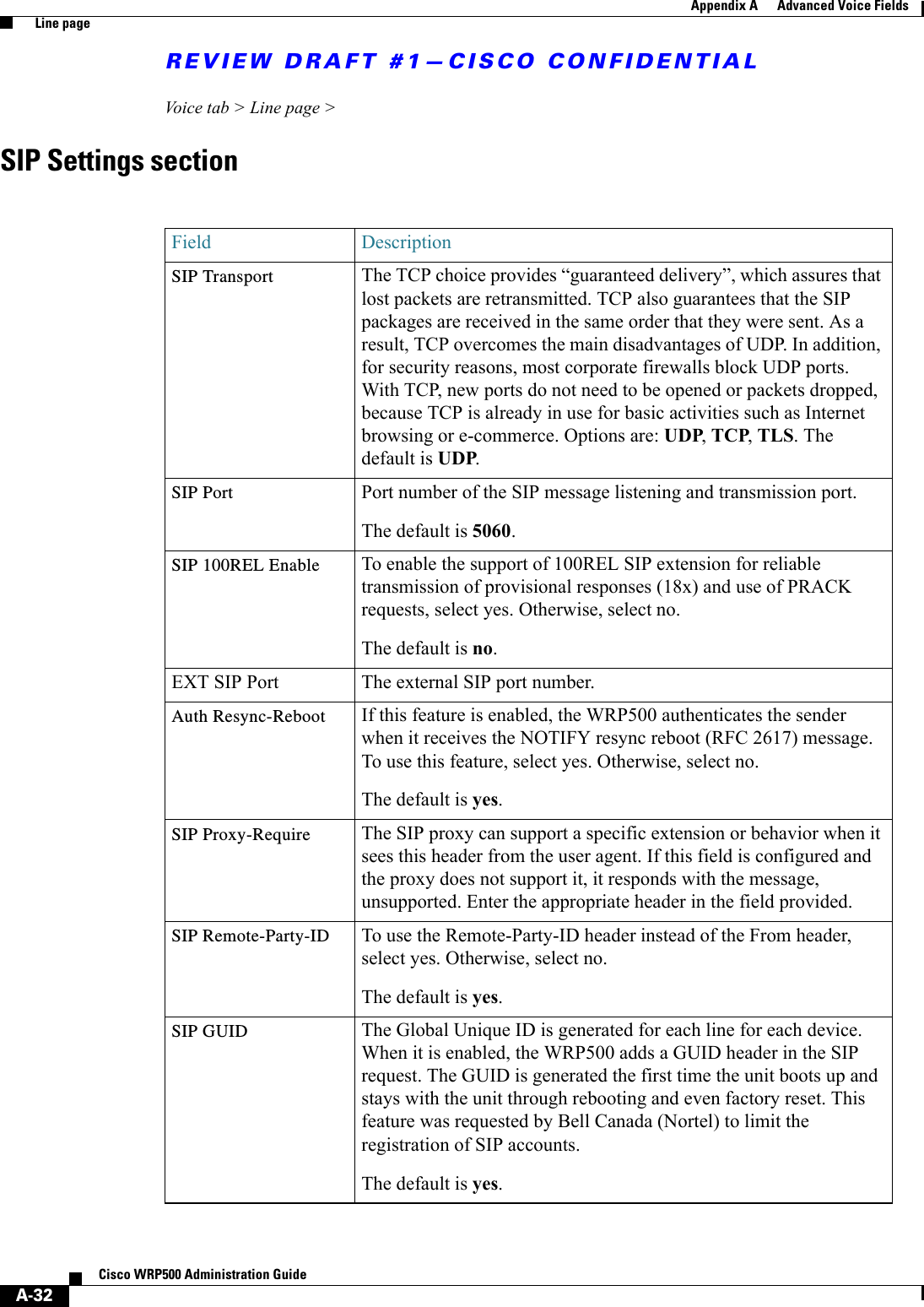
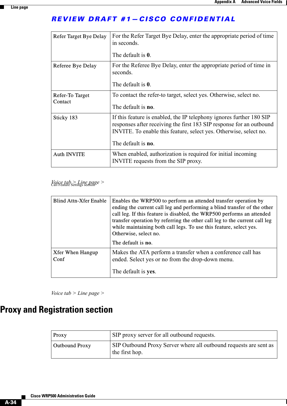
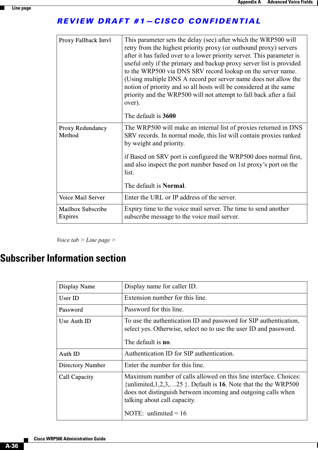
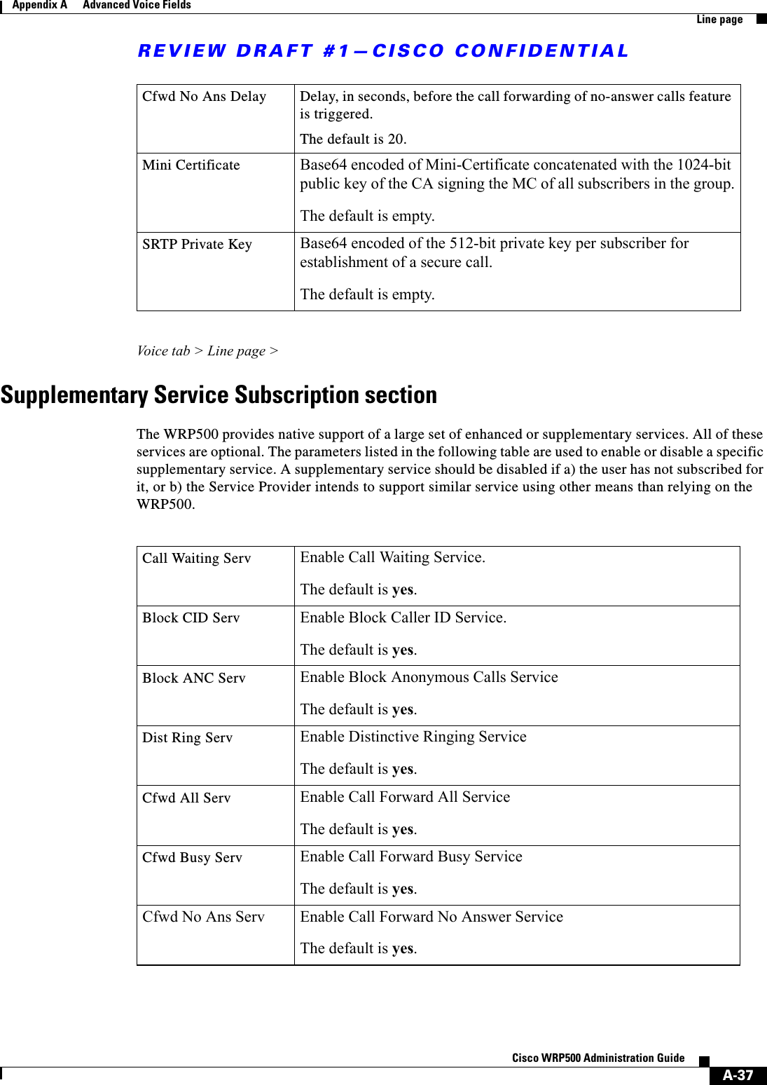
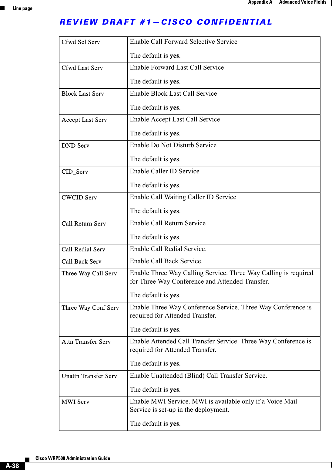
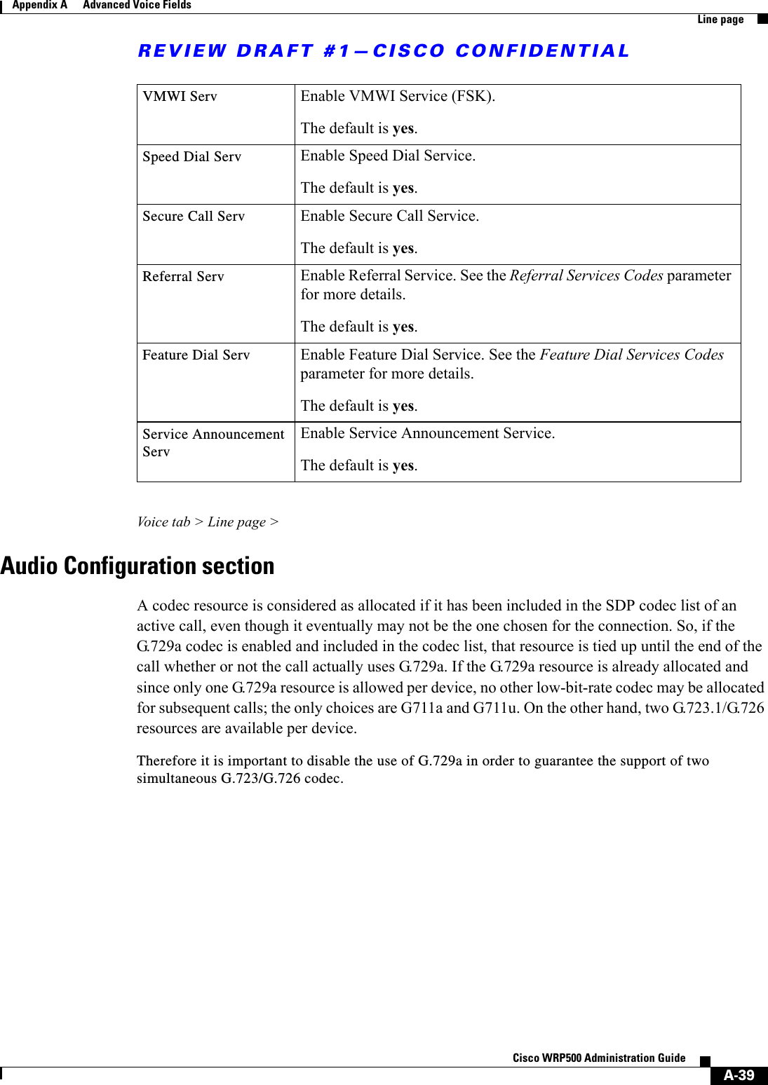
![REVIEW DRAFT #1—CISCO CONFIDENTIALA-29Cisco WRP500 Administration Guide Appendix A Advanced Voice Fields Line page•“SIP Settings section” section on page A-32•“Call Feature Settings section” section on page A-34•“Proxy and Registration section” section on page A-34•“Subscriber Information section” section on page A-36•“Supplementary Service Subscription section” section on page A-37•“Audio Configuration section” section on page A-39•“Dial Plan section” section on page A-40•“FXS Port Polarity Configuration section” section on page A-41In a configuration profile, the Line parameters must be appended with the appropriate numeral (for example, [1] or [2]) to identify the line to which the setting applies. Voice tab > Line page >Line Enable sectionVoice tab > Line page >Streaming Audio Server (SAS) sectionLine Enable To enable this line for service, select yes. Otherwise, select no.The default is yes.SAS Enable To enable the use of the line as a streaming audio source, select yes. Otherwise, select no. If enabled, the line cannot be used for outgoing calls. Instead, it auto-answers incoming calls and streams audio RTP packets to the caller.The default is no.SAS DLG Refresh Intvl If this value is not zero, it is the interval at which the streaming audio server sends out session refresh (SIP re-INVITE) messages to determine whether the connection to the caller is still active. If the caller does not respond to the refresh message, the WRP500 ends this call with a SIP BYE message. The range is 0 to 255 seconds (0 means that the session refresh is disabled).The default is 30.](https://usermanual.wiki/Cisco-Systems/WRP501156.User-Manual-1/User-Guide-2516588-Page-73.png)
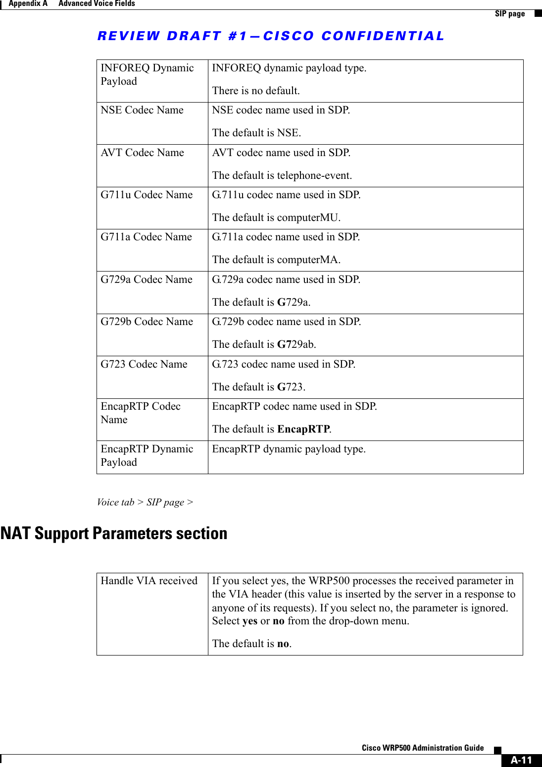
![REVIEW DRAFT #1—CISCO CONFIDENTIALA-31Cisco WRP500 Administration Guide Appendix A Advanced Voice Fields Line pageVoice tab > Line page >Network Settings sectionSIP ToS/DiffServ Value TOS/DiffServ field value in UDP IP packets carrying a SIP message.The default is 0x68.SIP CoS Value [0-7] CoS value for SIP messages.The default is 3.RTP ToS/DiffServ Val ue ToS/DiffServ field value in UDP IP packets carrying RTP data.The default is 0xb8.RTP CoS Value [0-7] CoS value for RTP data.The default is 6.Network Jitter Level Determines how jitter buffer size is adjusted by the WRP500. Jitter buffer size is adjusted dynamically. The minimum jitter buffer size is 30 milliseconds or (10 milliseconds + current RTP frame size), whichever is larger, for all jitter level settings. However, the starting jitter buffer size value is larger for higher jitter levels. This setting controls the rate at which the jitter buffer size is adjusted to reach the minimum. Select the appropriate setting: low, medium, high, very high, or extremely high.The default is high.Jitter Buffer AdjustmentControls how the jitter buffer should be adjusted. Select the appropriate setting: up and down, up only, down only, or disable.The default is up and down.](https://usermanual.wiki/Cisco-Systems/WRP501156.User-Manual-1/User-Guide-2516588-Page-75.png)
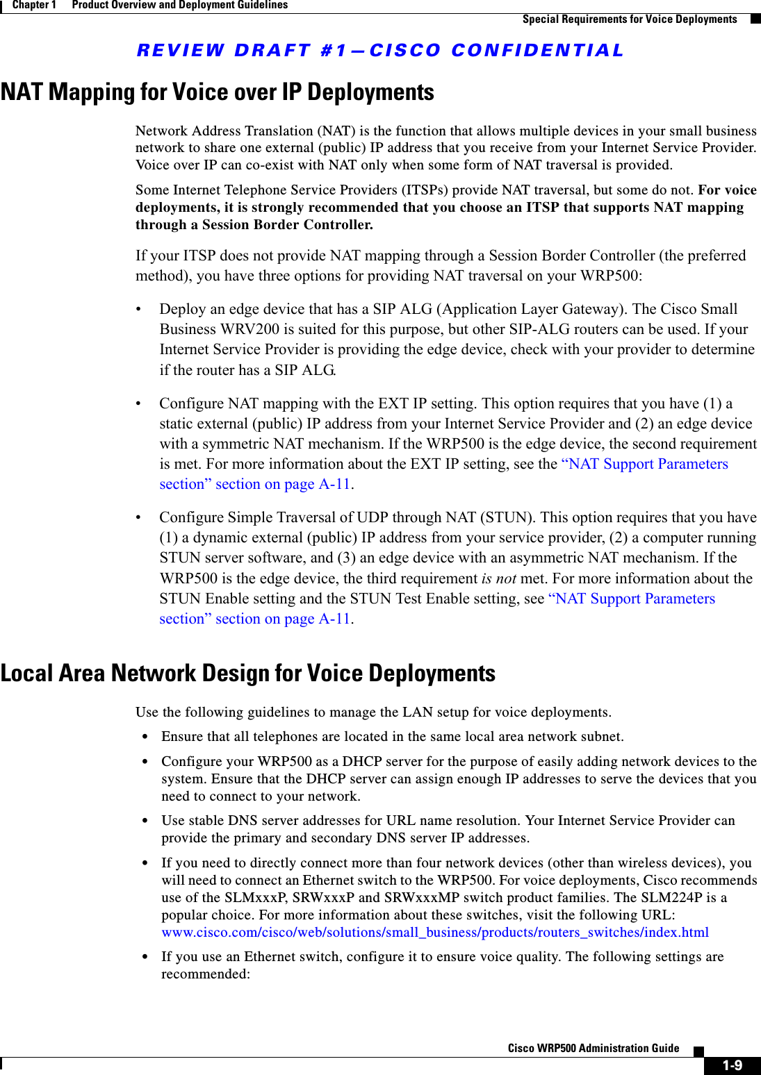
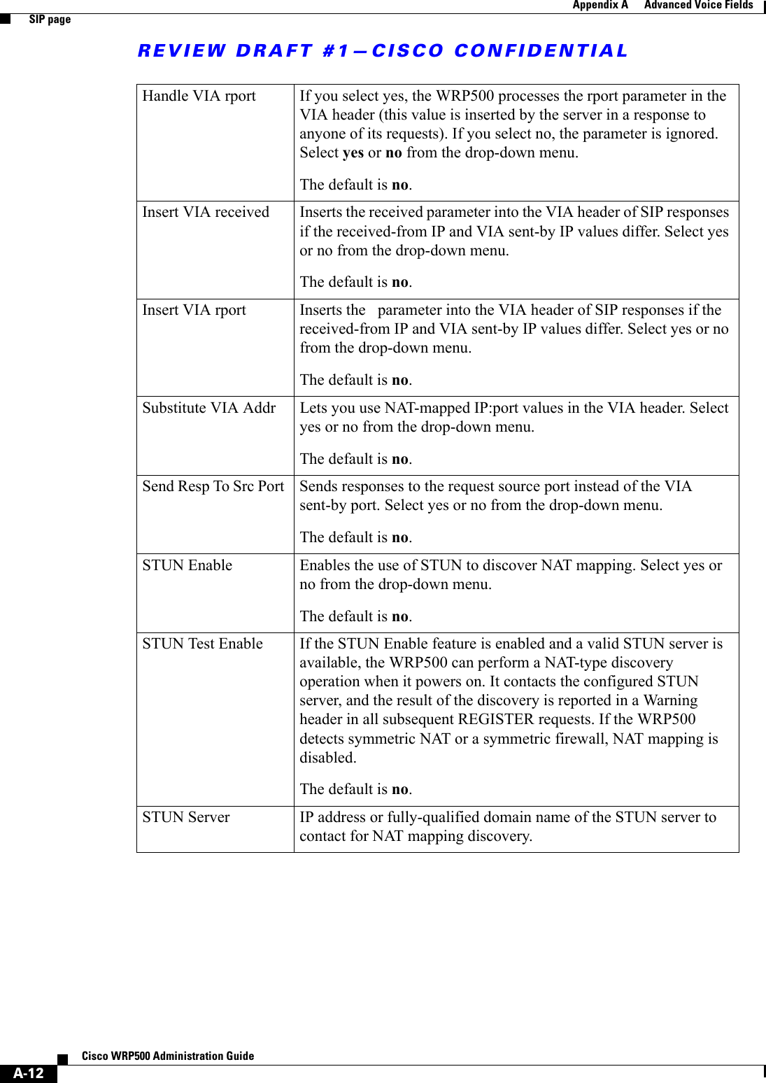
![REVIEW DRAFT #1—CISCO CONFIDENTIALA-40Cisco WRP500 Administration Guide Appendix A Advanced Voice Fields Line pageVoice tab > Line page >Dial Plan sectionThe default dial plan script for each line is as follows: (*xx|[3469]11|0|00|[2-9]xxxxxx|1xxx[2-9]xxxxxx|xxxxxxxxxxxx.). The syntax for a dial plan expression is as follows:Dial Plan Entry Functionality*xx Allow arbitrary 2 digit star code[3469]11 Allow x11 sequences0Operator00 Int’l Operator[2-9]xxxxxx US local number1xxx[2-9]xxxxxx US 1 + 10-digit long distance numberxxxxxxxxxxxx. Everything else (Int’l long distance, FWD, ...)Dial Plan Dial plan script for this line.The default is (*xx|[3469]11|0|00|[2-9]xxxxxx|1xxx[2-9]xxxxxxS0|xxxxxxxxxxxx.)Each parameter is separated by a semi-colon (;).Example 1:*1xxxxxxxxxx<:@fwdnat.pulver.com:5082;uid=jsmith;pwd=xyzExample 2:*1xxxxxxxxxx<:@fwd.pulver.com;nat;uid=jsmith;pwd=xyzExample 3:[39]11<:@gw0>](https://usermanual.wiki/Cisco-Systems/WRP501156.User-Manual-1/User-Guide-2516588-Page-84.png)
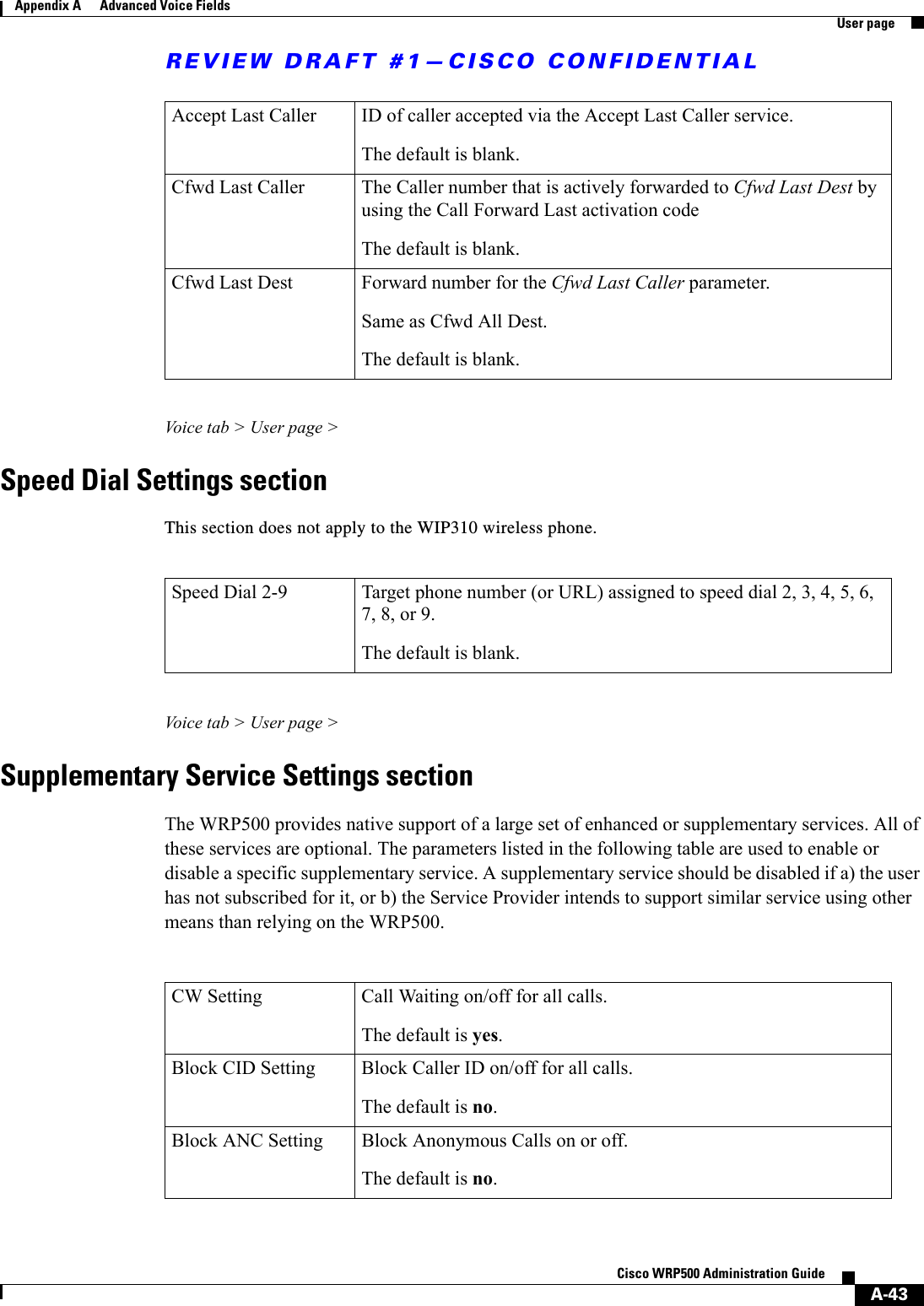
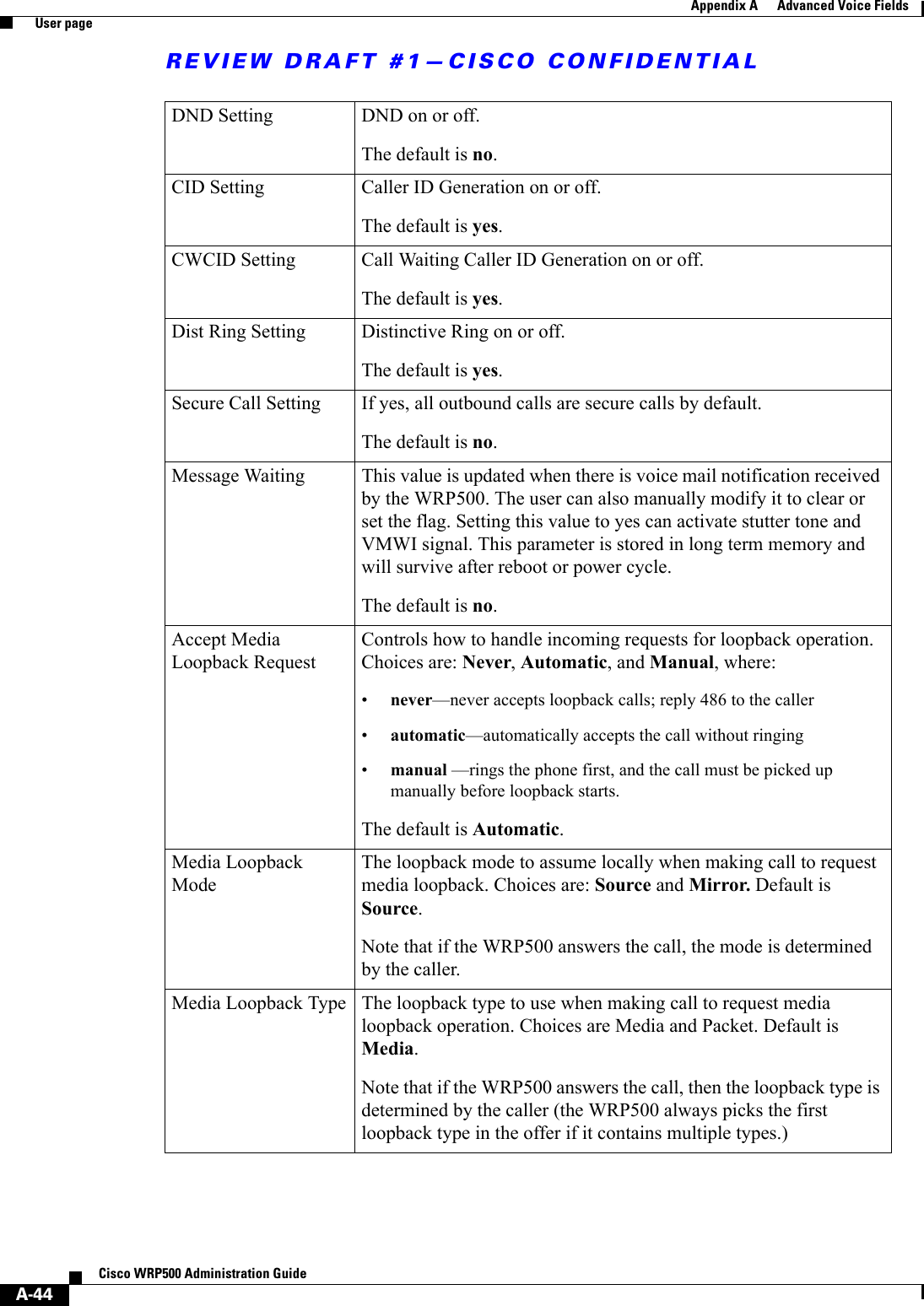
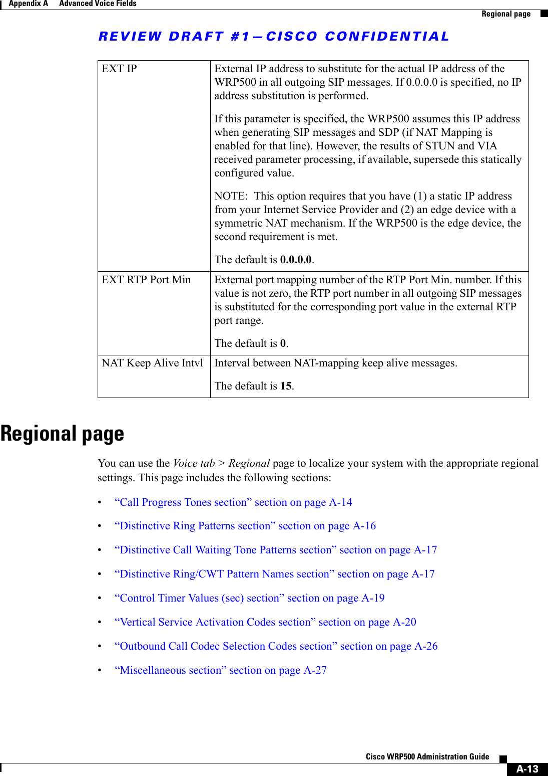
![REVIEW DRAFT #1—CISCO CONFIDENTIALA-41Cisco WRP500 Administration Guide Appendix A Advanced Voice Fields User pageVoice tab > Line page >FXS Port Polarity Configuration sectionUser pageYou can use this page to configure the user settings. This page includes the following sections:•“Call Forward Settings section” section on page A-42•“Selective Call Forward Settings section” section on page A-42•“Speed Dial Settings section” section on page A-43•“Supplementary Service Settings section” section on page A-43 •“Distinctive Ring Settings section” section on page A-45Enable IP Dialing Enable or disable IP dialing.If IP dialing is enabled, one can dial [user-id@]a.b.c.d[:port], where ‘@’, ‘.’, and ‘:’ are dialed by entering *, user-id must be numeric (like a phone number) and a, b, c, d must be between 0 and 255, and port must be larger than 255. If port is not given, 5060 is used. Port and User-Id are optional. If the user-id portion matches a pattern in the dial plan, then it is interpreted as a regular phone number according to the dial plan. The INVITE message, however, is still sent to the outbound proxy if it is enabled.The default is no. Emergency Number Comma separated list of emergency number patterns. If outbound call matches one of the pattern, the WRP500 will disable hook flash event handling. The condition is restored to normal after the phone is on-hook. Blank signifies no emergency number. Maximum number length is 63 characters.The default is blank. Idle Polarity Polarity before a call is connected: Forward or Reverse.The default is Forward.Caller Conn Polarity Polarity after an outbound call is connected: Forward or Reverse.The default is Forward.Callee Conn Polarity Polarity after an inbound call is connected: Forward or Reverse.The default is Forward.](https://usermanual.wiki/Cisco-Systems/WRP501156.User-Manual-1/User-Guide-2516588-Page-85.png)
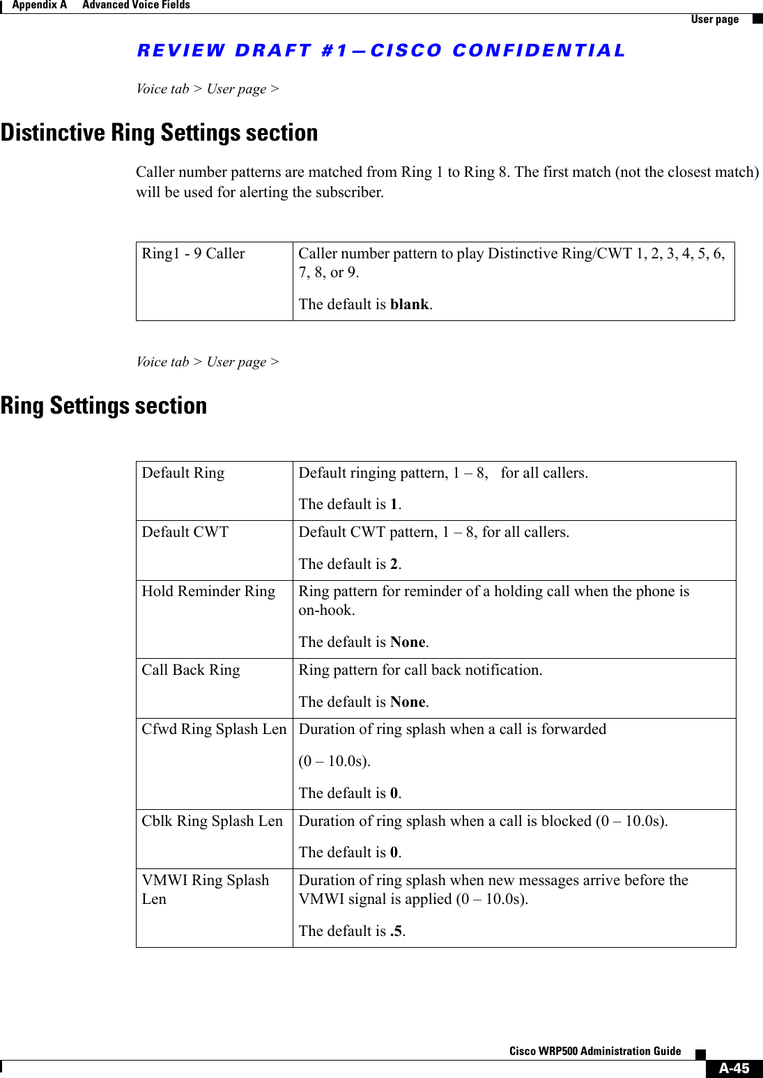
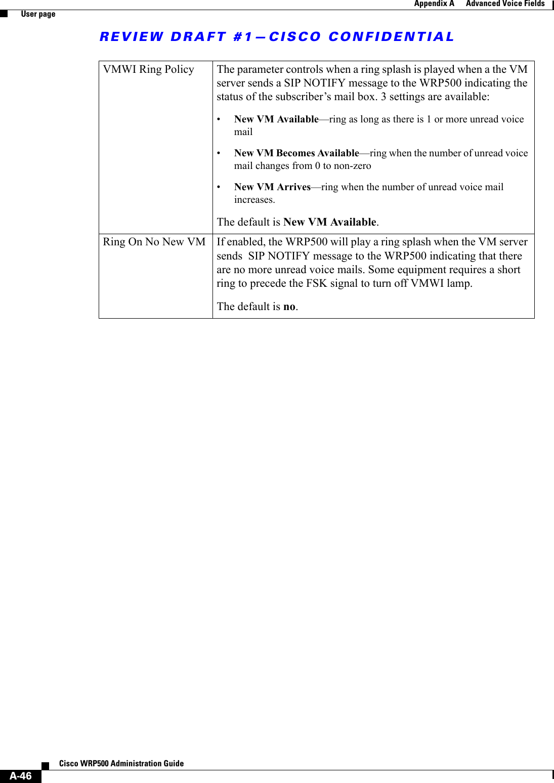
![REVIEW DRAFT #1—CISCO CONFIDENTIALA-42Cisco WRP500 Administration Guide Appendix A Advanced Voice Fields User page•“Ring Settings section” section on page A-45When a call is made from Line 1 or Line 2, the WRP500 uses the user and line settings for that line; there is no user login support. Per user parameter tags must be appended with [1] or [2] (corresponding to line 1 or 2) in the configuration profile. It is omitted below for readability. Voice tab > User page > Call Forward Settings sectionVoice tab > User page > Selective Call Forward Settings sectionCfwd All Dest Forward number for Call Forward All ServiceThe default is blank. Cfwd Busy Dest Forward number for Call Forward Busy Service. Same as Cfwd All Dest. The default is blank. Cfwd No Ans Dest Forward number for Call Forward No Answer Service. Same as Cfwd All Dest. The default is blank. Cfwd No Ans Delay Delay in sec before Call Forward No Answer triggers. Same as Cfwd All Dest. The default is 20. Cfwd Sel1- 8 Caller Caller number pattern to trigger Call Forward Selective 1, 2, 3, 4, 5, 6, 7, or 8.The default is blank. Cfwd Sel1 - 8 Dest Forward number for Call Forward Selective 1, 2, 3, 4, 5, 6, 7, or 8.Same as Cfwd All Dest. The default is blank. Block Last Caller ID of caller blocked via the Block Last Caller service.The default is blank.](https://usermanual.wiki/Cisco-Systems/WRP501156.User-Manual-1/User-Guide-2516588-Page-86.png)