Cisco Systems WRP501156 Dual Band Wireless Broadband Router User Manual wrp500 ata admin guide
Cisco Systems Inc Dual Band Wireless Broadband Router wrp500 ata admin guide
Contents
- 1. User Manual 1
- 2. User Manual 2
User Manual 1

REVIEW DRAFT #1—CISCO CONFIDENTIAL
Cisco Systems, Inc.
www.cisco.com
Cisco has more than 200 offices worldwide.
Addresses, phone numbers, and fax numbers
are listed on the Cisco website at
www.cisco.com/go/offices.
Cisco WRP500 Administration Guide
Wireless-G Broadband Router with 2 Phone Ports and Built-In Analog
Telephone Adapter
December 23, 2014
Last Updated: December 23, 2014
ADMINISTRATION GUIDE
REVIEW DRAFT #1—CISCO CONFIDENTIAL
THE SPECIFICATIONS AND INFORMATION REGARDING THE PRODUCTS IN THIS MANUAL ARE SUBJECT TO CHANGE WITHOUT NOTICE. ALL
STATEMENTS, INFORMATION, AND RECOMMENDATIONS IN THIS MANUAL ARE BELIEVED TO BE ACCURATE BUT ARE PRESENTED WITHOUT
WARRANTY OF ANY KIND, EXPRESS OR IMPLIED. USERS MUST TAKE FULL RESPONSIBILITY FOR THEIR APPLICATION OF ANY PRODUCTS.
THE SOFTWARE LICENSE AND LIMITED WARRANTY FOR THE ACCOMPANYING PRODUCT ARE SET FORTH IN THE INFORMATION PACKET THAT
SHIPPED WITH THE PRODUCT AND ARE INCORPORATED HEREIN BY THIS REFERENCE. IF YOU ARE UNABLE TO LOCATE THE SOFTWARE LICENSE
OR LIMITED WARRANTY, CONTACT YOUR CISCO REPRESENTATIVE FOR A COPY.
The following information is for FCC compliance of Class A devices: This equipment has been tested and found to comply with the limits for a Class A digital device, pursuant
to part 15 of the FCC rules. These limits are designed to provide reasonable protection against harmful interference when the equipment is operated in a commercial
environment. This equipment generates, uses, and can radiate radio-frequency energy and, if not installed and used in accordance with the instruction manual, may cause
harmful interference to radio communications. Operation of this equipment in a residential area is likely to cause harmful interference, in which case users will be required
to correct the interference at their own expense.
The following information is for FCC compliance of Class B devices: This equipment has been tested and found to comply with the limits for a Class B digital device, pursuant
to part 15 of the FCC rules. These limits are designed to provide reasonable protection against harmful interference in a residential installation. This equipment generates,
uses and can radiate radio frequency energy and, if not installed and used in accordance with the instructions, may cause harmful interference to radio communications.
However, there is no guarantee that interference will not occur in a particular installation. If the equipment causes interference to radio or television reception, which can be
determined by turning the equipment off and on, users are encouraged to try to correct the interference by using one or more of the following measures:
• Reorient or relocate the receiving antenna.
• Increase the separation between the equipment and receiver.
• Connect the equipment into an outlet on a circuit different from that to which the receiver is connected.
• Consult the dealer or an experienced radio/TV technician for help.
Modifications to this product not authorized by Cisco could void the FCC approval and negate your authority to operate the product.
The Cisco implementation of TCP header compression is an adaptation of a program developed by the University of California, Berkeley (UCB) as part of UCB’s public
domain version of the UNIX operating system. All rights reserved. Copyright © 1981, Regents of the University of California.
NOTWITHSTANDING ANY OTHER WARRANTY HEREIN, ALL DOCUMENT FILES AND SOFTWARE OF THESE SUPPLIERS ARE PROVIDED “AS IS” WITH
ALL FAULTS. CISCO AND THE ABOVE-NAMED SUPPLIERS DISCLAIM ALL WARRANTIES, EXPRESSED OR IMPLIED, INCLUDING, WITHOUT
LIMITATION, THOSE OF MERCHANTABILITY, FITNESS FOR A PARTICULAR PURPOSE AND NONINFRINGEMENT OR ARISING FROM A COURSE OF
DEALING, USAGE, OR TRADE PRACTICE.
IN NO EVENT SHALL CISCO OR ITS SUPPLIERS BE LIABLE FOR ANY INDIRECT, SPECIAL, CONSEQUENTIAL, OR INCIDENTAL DAMAGES, INCLUDING,
WITHOUT LIMITATION, LOST PROFITS OR LOSS OR DAMAGE TO DATA ARISING OUT OF THE USE OR INABILITY TO USE THIS MANUAL, EVEN IF CISCO
OR ITS SUPPLIERS HAVE BEEN ADVISED OF THE POSSIBILITY OF SUCH DAMAGES.
Cisco and the Cisco logo are trademarks or registered trademarks of Cisco and/or its affiliates in the U.S. and other countries. To view a list of Cisco trademarks, go to this
URL: www.cisco.com/go/trademarks. Third-party trademarks mentioned are the property of their respective owners. The use of the word partner does not imply a partnership
relationship between Cisco and any other company. (1110R)
Any Internet Protocol (IP) addresses and phone numbers used in this document are not intended to be actual addresses and phone numbers. Any examples, command display
output, network topology diagrams, and other figures included in the document are shown for illustrative purposes only. Any use of actual IP addresses or phone numbers in
illustrative content is unintentional and coincidental.
© 2015 Cisco Systems, Inc. All rights reserved.

iii
Cisco WRP500 Administration Guide
REVIEW DRAFT #1—CISCO CONFIDENTIAL
CONTENTS
CHAPTER
1Product Overview and Deployment Guidelines 1-1
WRP500 Features and Benefits 1-2
Deployment Models 1-3
WRP500 Deployment in a Basic Network 1-3
WRP500 Deployment with a Wireless Guest Network 1-4
WRP500 Deployment with Mobile Broadband 1-5
Mobile Office That Uses the Mobile Network for Internet Access 1-5
Basic Office Deployment That Uses the Mobile Network as a Backup Connection 1-6
Local Area Network Guidelines 1-6
Power, Cabling, and Telephone Lines 1-6
Basic Services and Equipment 1-7
Special Requirements for Voice Deployments 1-7
Bandwidth for Voice Deployments 1-7
NAT Mapping for Voice over IP Deployments 1-9
Local Area Network Design for Voice Deployments 1-9
WRP500 Maintenance Operations 1-10
Remote Provisioning 1-11
Upgrade URL 1-11
Resync URL 1-12
Reboot URL 1-12
Configuration Profile 1-12
XML Format 1-13
Binary Format 1-13
CHAPTER
2Configure Your System for ITSP Interoperability 2-1
Configure NAT Mapping 2-1
Configure NAT Mapping with a Static IP Address 2-1
Configure NAT Mapping with STUN 2-2
Determine Whether the Router Uses Symmetric or Asymmetric NAT 2-4
Firewalls and SIP 2-5
Configure SIP Timer Values 2-5

REVIEW DRAFT #1—CISCO CONFIDENTIAL
Contents
iv
Cisco WRP500 Administration Guide
CHAPTER
3Configure Voice Services 3-1
Analog Telephone Adapter Operations 3-1
ATA Software Features 3-2
Supported Codecs 3-2
SIP Proxy Redundancy 3-2
Other ATA Software Features 3-3
Register to the Service Provider 3-6
Manage Caller ID Service 3-7
Optimize Fax Completion Rates 3-8
Fax Troubleshooting 3-9
Silence Suppression and Comfort Noise Generation 3-10
Configure Dial Plans 3-10
About Dial Plans 3-11
Digit Sequences 3-11
Digit Sequence Examples 3-12
Acceptance and Transmission the Dialed Digits 3-14
Dial Plan Timer (Off-Hook Timer) 3-15
Interdigit Long Timer (Incomplete Entry Timer) 3-15
Interdigit Short Timer (Complete Entry Timer) 3-16
Edit Dial Plans 3-17
Enter the Line Interface Dial Plan 3-17
Reset the Control Timers 3-17
Secure Call Implementation 3-18
Enable Secure Calls 3-18
APPENDIX
AAdvanced Voice Fields A-1
Info page A-1
Product Information section A-2
System Status section A-2
Line Status section A-3
System page A-5
System Configuration section A-5
Miscellaneous Settings section A-5
SIP page A-6
SIP Parameters section A-6
SIP Timer Values (sec) section A-8
Response Status Code Handling section A-9
RTP Parameters section A-10

REVIEW DRAFT #1—CISCO CONFIDENTIAL
Contents
v
Cisco WRP500 Administration Guide
SDP Payload Types section A-10
NAT Support Parameters section A-11
Regional page A-13
Call Progress Tones section A-14
Distinctive Ring Patterns section A-16
Distinctive Call Waiting Tone Patterns section A-17
Distinctive Ring/CWT Pattern Names section A-17
Control Timer Values (sec) section A-19
Vertical Service Activation Codes section A-20
Outbound Call Codec Selection Codes section A-26
Miscellaneous section A-27
Line page A-28
Line Enable section A-29
Streaming Audio Server (SAS) section A-29
NAT Settings section A-30
Network Settings section A-31
SIP Settings section A-32
Proxy and Registration section A-34
Subscriber Information section A-36
Supplementary Service Subscription section A-37
Audio Configuration section A-39
Dial Plan section A-40
FXS Port Polarity Configuration section A-41
User page A-41
Call Forward Settings section A-42
Selective Call Forward Settings section A-42
Speed Dial Settings section A-43
Supplementary Service Settings section A-43
Distinctive Ring Settings section A-45
Ring Settings section A-45
APPENDIX
BData Fields B-1
Setup B-1
Setup > Basic Setup B-1
Setup > DDNS B-7
Setup > MAC Address Clone B-8
Setup > Advanced Routing B-8
Setup > Mobile Network B-9
Setup > Connection Recovery B-11

REVIEW DRAFT #1—CISCO CONFIDENTIAL
Contents
vi
Cisco WRP500 Administration Guide
Wireless Configuration B-12
Wireless > Basic Wireless Settings B-12
Wireless > Wireless Security B-13
Wireless > Wireless MAC Filter B-14
Wireless > Advanced Wireless Settings B-15
Security B-16
Security > Firewall B-16
Security > VPN Passthrough B-18
Access Restrictions B-18
Access Restrictions > Internet Access B-18
Applications and Gaming B-19
Applications and Gaming > Single Port Forwarding B-19
Applications and Gaming > Port Range Forwarding B-20
Applications & Gaming > Port Range Triggering B-21
Applications & Gaming > DMZ B-21
Applications and Gaming > QoS (Quality of Service) B-21
Administration B-23
Administration > Management B-23
Administration > Log B-25
Administration > Diagnostics B-26
Administration > Factory Defaults B-26
Status B-26
Status > Router B-27
Status > Mobile Network B-27
Status > Local Network B-28
Status > Wireless Network B-28
APPENDIX
CTroubleshooting C-1
APPENDIX
DEnvironmental Specifications for the WRP500 D-1
APPENDIX
EWhere to Go From Here E-1

CHAPTER
REVIEW DRAFT #1—CISCO CONFIDENTIAL
1-1
Cisco WRP500 Administration Guide
1
Product Overview and Deployment Guidelines
This chapter describes the features and benefits of the WRP500, describes deployment scenarios, and
offers guidelines to help you plan your network.
•“WRP500 Features and Benefits,” on page 2
•“Deployment Models,” on page 3
•“Local Area Network Guidelines,” on page 6
•“Special Requirements for Voice Deployments,” on page 7
•“WRP500 Maintenance Operations,” on page 10
•“Remote Provisioning,” on page 11

REVIEW DRAFT #1—CISCO CONFIDENTIAL
1-2
Cisco WRP500 Administration Guide
Chapter 1 Product Overview and Deployment Guidelines
WRP500 Features and Benefits
WRP500 Features and Benefits
With a variety of features, the WRP500 offers the benefits of five devices in one:
1. Router: The WRP500 is a broadband router with a robust security firewall to protect your network.
2. Switch: The WRP500 includes a built-in, 4-port, full-duplex, 10/100 Ethernet switch to connect
computers, printers, and other equipment directly or to attach additional hubs and switches.
Advanced Quality of Service functionality ensures that you can prioritize traffic for data, voice, and
video applications.
3. Analog Telephone Adapter: The WRP500 includes a two-port Analog Telephone Adapter (ATA)
that allows you to connect your analog phones or fax machines to your configured Internet telephone
service. Two traditional phone lines also can be connected for support of legacy phone numbers and
fax numbers.
4. Wireless Access Point: The WRP500 has an integrated 802.11b/g wireless access point that secures
your communications with WEP and WPA security protocols. It is preconfigured to support two
wireless networks: one for transferring general data, such as data from a connected PC; and another
for transferring data from voice devices, such as audio or fax data.
5. Mobile Broadband Router: When you attach a compatible Mobile Broadband Modem to the USB
port, the WRP500 allows multiple Wi-Fi devices to share a mobile broadband connection. This
feature also can be used to provide continuous Internet service by providing automatic failover to
the mobile network when the primary Internet connection is unavailable. For the latest copy of the
USB Modem Compatibility List, visit the following URL:
www.cisco.com/en/US/products/ps10028/index.html
REVIEW DRAFT #1—CISCO CONFIDENTIAL
1-3
Cisco WRP500 Administration Guide
Chapter 1 Product Overview and Deployment Guidelines
Deployment Models
Note Because this device has many unique functions, the administrative tasks for the WRP500 may be
different from corresponding tasks on other Cisco Small Business routers, switches, and ATAs.
Administrators should refer to this guide for the proper procedures for installation, configuration, and
management of the WRP500.
Deployment Models
The versatility of the WRP500 makes it useful for a variety of deployments. Three are described in this
section.
•WRP500 Deployment in a Basic Network, page 1-3
•WRP500 Deployment with a Wireless Guest Network, page 1-4
•WRP500 Deployment with Mobile Broadband, page 1-5
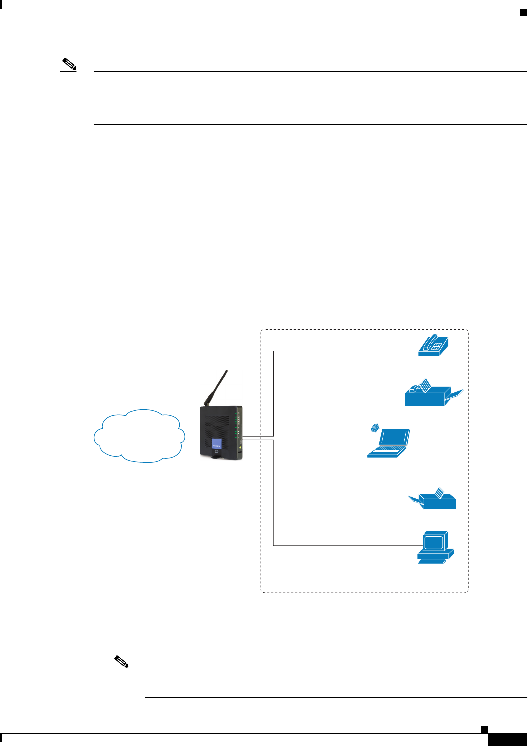
WRP500 Deployment in a Basic Network
In this scenario, the WRP500 is deployed in a small business that has a basic network configuration.
•The WRP500 is preconfigured by the Service Provider to act as the edge device that routes traffic
between the small business network and the Service Provider network.
Note The WRP500 may be configured as an edge device or can be connected to another device
that provides access to the Service Provider network.
Personal
computer
WRP400 Laptop
computer
Analog phone
Fax
Printer
Private Network
Internet
194231
REVIEW DRAFT #1—CISCO CONFIDENTIAL
1-4
Cisco WRP500 Administration Guide
Chapter 1 Product Overview and Deployment Guidelines
Deployment Models
•The WRP500 connects the computers to the Internet. Computers may be connected by network
cables or may operate wirelessly. All computers have access to the printer on the local network.
•An analog phone and a fax machine are connected to the WRP500 phone ports and have access to
the configured Voice over IP services.
WRP500 Deployment with a Wireless Guest Network
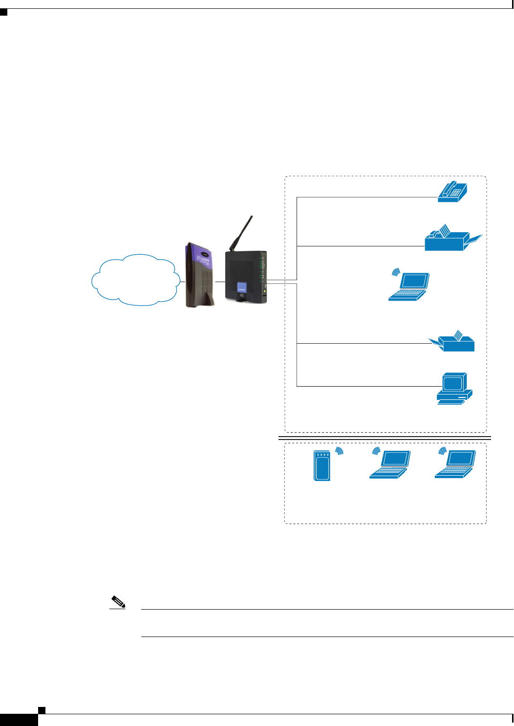
In this example, the WRP500 is deployed in an Internet cafe.
•The WRP500 is connected to a cable modem that provides Internet access.
Note The WRP500 may be configured as an edge device or can be connected to another device
that provides access to the Service Provider network.
Internet Access
Device
Wireless Guest Network
Personal
computer
WRP400 Laptop
computer
Analog phone
Fax
Printer
Private Network
Internet
194232
REVIEW DRAFT #1—CISCO CONFIDENTIAL
1-5
Cisco WRP500 Administration Guide
Chapter 1 Product Overview and Deployment Guidelines
Deployment Models
•In the private network, a computer is connected to the WRP500 by an Ethernet cable. The manager
also has a laptop computer that can be used wirelessly from anywhere on the premises, using the
main wireless network, SSID1. The manager and employees using SSID1 have access to the printer.
If desired, a wireless phone also could be connected to this network for business use.
•An analog phone and a fax machine are in the private network. The WRP500 is configured for
Internet telephone service and for traditional telephone service through a connected phone line.
•The WRP500 is configured with a guest network, SSID2, that enables the business to provide its
customers with a free wireless hotspot for their laptop computers and other mobile devices. Because
this network is separate from the main wireless network, the customers have no access to the
manager’s computer, the printer, or the telephone service.
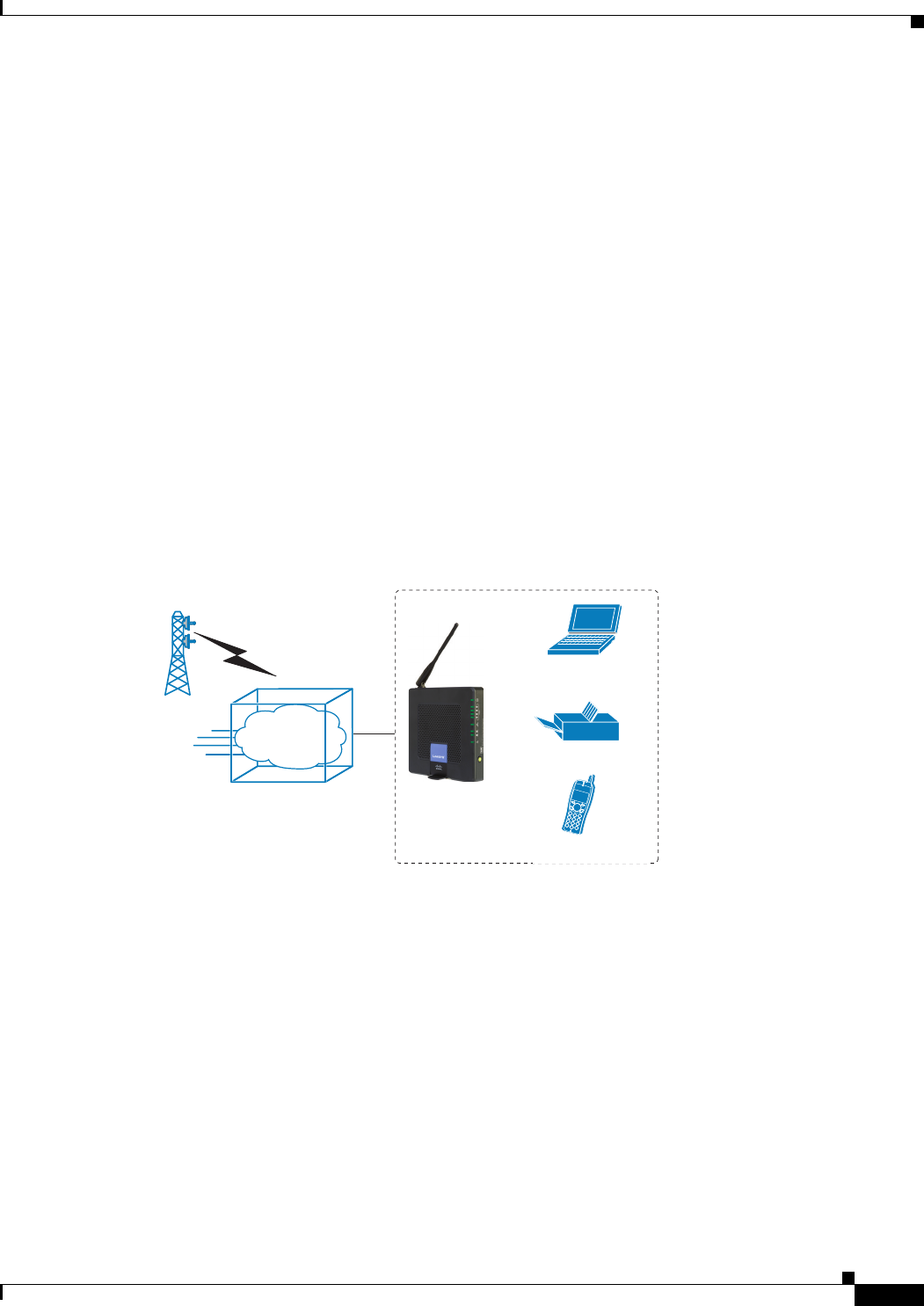
WRP500 Deployment with Mobile Broadband
When a compatible mobile broadband modem is connected to the USB port, the WRP500 can connect
to a mobile broadband network. The mobile network can be the primary network or can serve as a backup
network to ensure continuous Internet connectivity. Consider the two scenarios illustrated below.
Mobile Office That Uses the Mobile Network for Internet Access
In this example, a team has set up a temporary network at a construction site. The team members have
laptop computers and Wi-Fi phones that share a mobile broadband connection for Internet access. All
computers can connect to the printer on the local network. If a Virtual Private Network (VPN) tunnel is
configured on the laptop computer, team members also can securely connect to resources at the main
office (not illustrated).
WRP400*
Laptop
computer
Printer
Wi-Fi Phone
Mobile Office Network
1
Mobile
network
194234
*with compatible 3G USB Modem
*with compatible 3G USB Modem
WRP500*
Wi-Fi Phone
REVIEW DRAFT #1—CISCO CONFIDENTIAL
1-6
Cisco WRP500 Administration Guide
Chapter 1 Product Overview and Deployment Guidelines
Local Area Network Guidelines
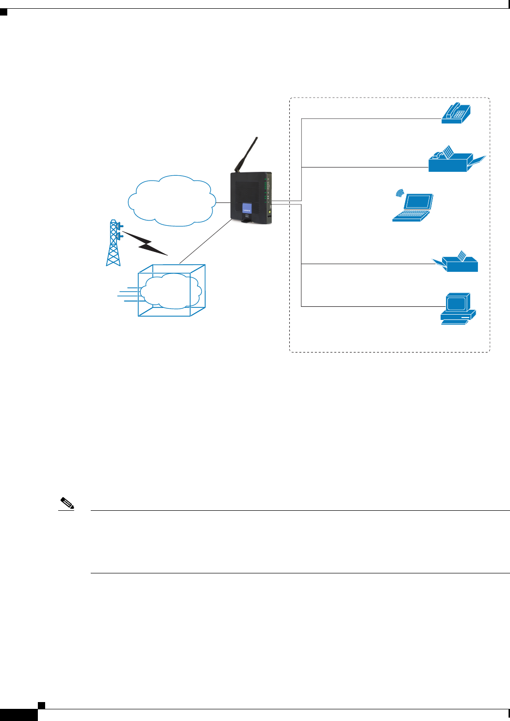
Basic Office Deployment That Uses the Mobile Network as a Backup Connection
In this example, the business has the same network as illustrated in WRP500 Deployment in a Basic
Network, page 1-3. However, this business has the added benefit of using the mobile broadband network
as a backup network to ensure continuous Internet connectivity. In the event that the Internet connection
fails, the WRP500 fails over to the configured mobile network. When the Internet connection becomes
available, the WRP500 recovers the connection.
Local Area Network Guidelines
This section offers guidelines for setting up your Local Area Network (LAN).
Note As you design your network, be aware that the WRP500 is intended for deployment in a very small
business. The router is designed to handle the data, voice, and video traffic that would be expected by
office personnel who use the Internet to find data, conduct phone conversations, transmit email, and
participate in videoconferences. For large-scale operations with heavy data, voice, and video
requirements, consider other models of Cisco Small Business routers.
Power, Cabling, and Telephone Lines
•AC outlets: Ensure there is an AC outlet available for every network device that requires AC
power.
–
The WRP500 requires power, and Ethernet switches (optional) require power.
Personal
computer
WRP400 Laptop
computer
Analog phone
Fax
Printer
Private Network
Internet
194233
1
Mobile
network
Failov
e
r
*with compatible 3G USB Modem
WRP500*

REVIEW DRAFT #1—CISCO CONFIDENTIAL
1-7
Cisco WRP500 Administration Guide
Chapter 1 Product Overview and Deployment Guidelines
Special Requirements for Voice Deployments
–
Some analog telephones require AC power.
•Ethernet cabling: If an Internet access device is present, you will need to connect it to the
WRP500 with an Ethernet cable. You also will need Ethernet cable for any devices that do not
have wireless connectivity. It is recommended that Ethernet cables are UTP Cat5e or better.
•PSTN lines: Ensure that the lines are operative and that any features, such as caller
identification, operate properly before starting the installation.
•UPS: It is strongly recommended that you included an Uninterrupted Power Supply (UPS)
mechanism in your network to ensure continuous operation during a power failure. Connect all
essential devices, including the Internet access device, WRP500, and the Ethernet switch (if
present).
Basic Services and Equipment
The following basic services and equipment are required:
• An Integrated access device or modem for broadband access to the Internet
• Business grade Internet service
• Internet Telephony Service Provider (ITSP) for Voice Over IP telephone service, supporting a
“bring your own device” model
• A computer with Microsoft Windows XP or Windows Vista for system configuration
Special Requirements for Voice Deployments
Voice deployments have special requirements that you must meet to ensure voice quality.
•“Bandwidth for Voice Deployments,” on page 7
•“NAT Mapping for Voice over IP Deployments,” on page 9
•“Local Area Network Design for Voice Deployments,” on page 9
Bandwidth for Voice Deployments
You can choose from several types of broadband access technologies to provide symmetric or
asymmetric connectivity to a small business. These technologies vary on the available bandwidth and on
the quality of service. For voice deployments, it is generally recommended that you use broadband
access with a Service Level Agreement that provides quality of service. If there is not a Service Level
Agreement with regard to the broadband connection quality of service, the downstream audio quality
may be affected negatively under heavy load conditions (bandwidth utilization beyond 80%).
To eliminate or minimize this effect, Cisco recommends one of the following actions:
• For broadband connections with a bandwidth lower than 2 Mbps, perform the call capacity
calculations by assuming a bandwidth value of 50% of the existing broadband bandwidth. For

REVIEW DRAFT #1—CISCO CONFIDENTIAL
1-8
Cisco WRP500 Administration Guide
Chapter 1 Product Overview and Deployment Guidelines
Special Requirements for Voice Deployments
example, in the case of a 2 Mbps uplink broadband connection, assume 1 Mbps. Limit the
uplink bandwidth in the Integrated Access Device to this value. This setting helps to maintain
the utilization levels below 60%, thus reducing jitter and packet loss.
• Use an additional broadband connection for voice services only. A separate connection is
required when the broadband connection services do not offer quality of service and when it is
not possible to apply the above mentioned utilization mechanism.
The available connection bandwidth determines the maximum number of simultaneous calls that the
system can support with the appropriate audio quality. Use this information to determine the maximum
number of simultaneous VoIP connections that the system can support.
For asymmetric connections, such as ADSL, the maximum number of calls is determined by the
upstream bandwidth. In general it is a good practice to use no more than 75% of the total available
bandwidth for calls. This provides space for data traffic and helps ensure good voice quality.
Note Some ITSP SIP trunk services limit the maximum number of simultaneous calls. Please check with your
Service Provider to understand the maximum number of simultaneous calls each SIP trunk supports.
The following table provides the approximate bandwidth budget for different codecs.
Note The Cisco WRP500 supports only the G.711 and G.729 codecs.
For more information about bandwidth calculation, refer to the following web sites:
www.erlang.com/calculator/lipb/
www.bandcalc.com/
Codec Approximate bandwidth
budget for each side of
conversation
2 calls 4 calls 6 calls 8 calls
G.711 110 kbps 220 kbps 440 kbps 660 kbps 880 kbps
G.726-4
0
87 kbps 174 kbps 348 kbps 522 kbps 696 kbps
G.726-3
2
79 kbps 158 kbps 316 kbps 474 kbps 632 kbps
G.726-2
4
71 kbps 142 kbps 284 kbps 426 kbps 568 kbps
G.726-1
6
63 kbps 126 kbps 252 kbps 378 kbps 504 kbps
G.729 55 kbps 110 kbps 220 kbps 330 kbps 440 kbps

REVIEW DRAFT #1—CISCO CONFIDENTIAL
1-9
Cisco WRP500 Administration Guide
Chapter 1 Product Overview and Deployment Guidelines
Special Requirements for Voice Deployments
NAT Mapping for Voice over IP Deployments
Network Address Translation (NAT) is the function that allows multiple devices in your small business
network to share one external (public) IP address that you receive from your Internet Service Provider.
Voice over IP can co-exist with NAT only when some form of NAT traversal is provided.
Some Internet Telephone Service Providers (ITSPs) provide NAT traversal, but some do not. For voice
deployments, it is strongly recommended that you choose an ITSP that supports NAT mapping
through a Session Border Controller.
If your ITSP does not provide NAT mapping through a Session Border Controller (the preferred
method), you have three options for providing NAT traversal on your WRP500:
• Deploy an edge device that has a SIP ALG (Application Layer Gateway). The Cisco Small
Business WRV200 is suited for this purpose, but other SIP-ALG routers can be used. If your
Internet Service Provider is providing the edge device, check with your provider to determine
if the router has a SIP ALG.
• Configure NAT mapping with the EXT IP setting. This option requires that you have (1) a
static external (public) IP address from your Internet Service Provider and (2) an edge device
with a symmetric NAT mechanism. If the WRP500 is the edge device, the second requirement
is met. For more information about the EXT IP setting, see the “NAT Support Parameters
section” section on page A-11.
• Configure Simple Traversal of UDP through NAT (STUN). This option requires that you have
(1) a dynamic external (public) IP address from your service provider, (2) a computer running
STUN server software, and (3) an edge device with an asymmetric NAT mechanism. If the
WRP500 is the edge device, the third requirement is not met. For more information about the
STUN Enable setting and the STUN Test Enable setting, see “NAT Support Parameters
section” section on page A-11.
Local Area Network Design for Voice Deployments
Use the following guidelines to manage the LAN setup for voice deployments.
•Ensure that all telephones are located in the same local area network subnet.
•Configure your WRP500 as a DHCP server for the purpose of easily adding network devices to the
system. Ensure that the DHCP server can assign enough IP addresses to serve the devices that you
need to connect to your network.
•Use stable DNS server addresses for URL name resolution. Your Internet Service Provider can
provide the primary and secondary DNS server IP addresses.
•If you need to directly connect more than four network devices (other than wireless devices), you
will need to connect an Ethernet switch to the WRP500. For voice deployments, Cisco recommends
use of the SLMxxxP, SRWxxxP and SRWxxxMP switch product families. The SLM224P is a
popular choice. For more information about these switches, visit the following URL:
www.cisco.com/cisco/web/solutions/small_business/products/routers_switches/index.html
•If you use an Ethernet switch, configure it to ensure voice quality. The following settings are
recommended:

REVIEW DRAFT #1—CISCO CONFIDENTIAL
1-10
Cisco WRP500 Administration Guide
Chapter 1 Product Overview and Deployment Guidelines
WRP500 Maintenance Operations
–
Enable Port Fast and Spanning Tree Protocol on the ports to which your voice devices are
connected. The Cisco phones are capable of rebooting in a few seconds and will attempt to
locate network services while a switch port is being blocked by STP after it senses a device
reboot. Enabling Port Fast means that the network will be available to the phones when needed.
If the switch does not provide a way to enable Port Fast, then you must disable Spanning Tree
Protocol.
–
In the administrative web pages for the switch, you should enable QoS and choose DSCP as the
Trust Mode.
WRP500 Maintenance Operations
Due to its unique functions, the WRP500 has unique maintenance operations as compared to other Cisco
Small Business IP telephony devices.
Note For complete instructions about the settings mentioned below, see the WRP500 User Guide.
•Remote Management: For security purposes, remote management is disabled by default.
–
When you first configure the WRP500, connect your administrative computer directly to one of
the LAN ports and enter the default static IP address into your web browser to log on to the
configuration utility.
Note The default LAN IP address of the WRP500 is 192.168.15.1. If another device on the
network has the same IP address, the WRP500 will take the address 192.168.16.1. You can
modify the Local IP Address on the Interface Setup tab > LAN > DHCP Server section.
If you are using the IVR, be aware that this address is NOT the address reported by the 110
option of the IVR. The device does not respond to the 110 option address.
–
If you wish to enable web access and wireless access to the configuration utility, you can use
the Administration tab > Web Access Management section.
•DHCP Server: The DCHP server on LAN ports is enabled by default. This setting is on the Interface
Setup tab > LAN > DHCP Server section.
•System Logging: If you wish to enable system logging, be aware that there are two sets of system
logs: one for the data (router) functions and another for the voice functions.
–
Data (router) logging: See the Administration tab > Log page.
–
Voice logging: See the Voice tab > System page, Miscellaneous Settings section.
•Factory Reset: If you wish to reset your WRP500 to the factory default settings, you can reset the
data (router) settings and the voice settings separately.
Factory reset of data (router) settings: Use one of the following methods:
–
Option 1: Log on to the configuration utility, and then click Administration > Factory Defaults.
Next to Restore Router Factory Defaults, click Yes. Then click Save Settings to begin the
operation.
–
Option 2: Press and hold the reset button located on the side panel for approximately ten
seconds.

REVIEW DRAFT #1—CISCO CONFIDENTIAL
1-11
Cisco WRP500 Administration Guide
Chapter 1 Product Overview and Deployment Guidelines
Remote Provisioning
Factory reset of voice settings: Use one of the following methods:
–
Option 1: Log on to the configuration utility, and then click Administration tab > Factory
Defaults. Next to Restore Voice Factory Defaults, click Yes. Then click Save Settings to begin
the operation.
–
Option 2: Connect an analog phone to the Phone 1 or Phone 2 port. Press **** to access the
Interactive Voice Response menu. After you hear the greeting, press 73738 for factory reset.
Listen to the prompts and then press 1 to confirm or * to cancel. After you hear “Option
successful,” you can hang up the phone.
Remote Provisioning
Like other Cisco Small Business IP Telephony Devices, the WRP500 provides for secure provisioning
and remote upgrade. Provisioning is achieved through configuration profiles transferred to the device via
TFTP, HTTP, or HTTPS. To configure Provisioning, go to the Provisioning tab in the Configuration
Utility.
Note For complete details, see the Provisioning Guide at the following URL:
www.cisco.com/en/US/docs/voice_ip_comm/csbpvga/ata/provisioning/guide/Cisco_Small_Business_I
P_Telephony_Provisioning_Guide.pdf
Upgrade URL
Remote firmware upgrade is achieved via TFTP or HTTP (firmware upgrades using HTTPS are not
supported). Remote upgrades are initiated by causing the WRP500 to request the upgrade firmware
image by providing a URL for the WRP500 to retrieve the firmware.
Note If the value of the Upgrade Enable parameter in the Provisioning page is No, you cannot upgrade the
WRP500 even if the web page indicates otherwise.
The syntax of the Upgrade URL is as follows:
http://WRP500_ip_address/admin/upgrade?[protocol://][server-name[:port]][/firmware-pathname]
Both HTTP and TFTP are supported for the upgrade operation.
If no protocol is specified, TFTP is assumed. If no server-name is specified, the host that requests the
URL is used as server-name.
If no port specified, the default port of the protocol is used. (69 for TFTP or 80 for HTTP)
The firmware-pathname is typically the file name of the binary located in a directory on the TFTP or
HTTP server. If no firmware-pathname is specified, /spa.bin is assumed, as in the following example:
http://192.168.2.217/admin/upgrade?tftp://192.168.2.251/spa.bin

REVIEW DRAFT #1—CISCO CONFIDENTIAL
1-12
Cisco WRP500 Administration Guide
Chapter 1 Product Overview and Deployment Guidelines
Remote Provisioning
Resync URL
The WRP500 can be configured to automatically resync its internal configuration state to a remote
profile periodically and on power up. The automatic resyncs are controlled by configuring the desired
profile URL into the device.
The Resync URL lets you force the WRP500 to do a resync to a profile specified in the URL,
which can identify either a TFTP, HTTP, or HTTPS server. The syntax of the Resync URL is as
follows:
http://WRP500_ip_address/admin/resync?[[protocol://][server-name[:port]]/profile-pathname]
Note The WRP500 resyncs only when it is idle.
If no port is specified, the default port is used (69 for TFTP, 80 for HTTP, and 443 for HTTPS).
The profile-path is the path to the new profile with which to resync, for example:
http://192.168.2.217/admin/resync?tftp://192.168.2.251/spaconf.xml
Reboot URL
The Reboot URL lets you reboot the WRP500. The Reboot URL is as follows:
http://WRP500_ip_address/admin/reboot
Note The WRP500 reboots only when it is idle.
Configuration Profile
Because the WRP500 has two sets of parameters, one set for data and one set for voice, the
requirements vary from the provisioning of other Cisco Small Business IP Telephony Devices.
You will have two profiles: one for the data (router) parameters and one for the voice parameters.
One benefit of having separate profiles for voice parameters and data parameters is that you can
deploy the common data parameters to all of your customer sites and deploy the custom voice
parameters to each site individually.
•Data (router) parameters: Use the XML format only, as described in the Provisioning Guide. For
more information about the data parameters, see Appendix B, “Data Fields.”
•Voice parameters: Use the XML format. The binary format is generated by a profile compiler tool
available from Cisco. Find the correct SPA Profiler Compiler (SPC) for the firmware that you have
installed on your WRP500. For more information about the data parameters, see Appendix A, “.”
Note You can download the SPC at the following URL: tools.cisco.com/support/
downloads/go/Redirect.x?mdfid=282414113

REVIEW DRAFT #1—CISCO CONFIDENTIAL
1-13
Cisco WRP500 Administration Guide
Chapter 1 Product Overview and Deployment Guidelines
Remote Provisioning
XML Format
Use the XML format for data (router) parameters. The XML file consists of a series of elements (one per
configuration parameter), encapsulated within the element tags <flat-profile> … </flat-profile>. The
encapsulated elements specify values for individual parameters. Here is an example of a valid XML
profile:
<flat-profile>
<Admin_Passwd>some secret</Admin_Passwd>
<Upgrade_Enable>Yes</Upgrade_Enable>
</flat-profile>
The names of parameters in XML profiles can generally be inferred from the WRP500 Configuration
Utility, by substituting underscores (_) for spaces and other control characters. To distinguish between
Lines 1, 2, 3, and 4, corresponding parameter names are augmented by the strings _1_, _2_, _3_, and
_4_. For example, Line 1 Proxy is named Proxy_1_ in XML profiles. For more information, see
Appendix C, “WRP500 Provisioning Reference.”
Binary Format
The WRP500 does not support binary format files.

REVIEW DRAFT #1—CISCO CONFIDENTIAL
1-14
Cisco WRP500 Administration Guide
Chapter 1 Product Overview and Deployment Guidelines
Remote Provisioning

CHAPTER
REVIEW DRAFT #1—CISCO CONFIDENTIAL
2-1
Cisco WRP500 Administration Guide
2
Configure Your System for ITSP Interoperability
This chapter provides configuration details to help you to ensure that your infrastructure properly
supports voice services.
•“Configure NAT Mapping,” on page 1
•“Firewalls and SIP,” on page 5
•“Configure SIP Timer Values,” on page 5
Configure NAT Mapping
As discussed in Chapter 1, “Product Overview and Deployment Guidelines,” some form of NAT
mapping is needed to support VoIP. If your ITSP does not support NAT mapping through a Session
Border Controller, and your edge device is not a SIP-ALG router, you can address this issue through one
of the following methods:
•“Configure NAT Mapping with a Static IP Address,” on page 1
•“Configure NAT Mapping with STUN,” on page 2
Configure NAT Mapping with a Static IP Address
This option can be used if the following requirements are met:
•You must have a static external (public) IP address from your ISP.
•The edge device—that is, the router between your local area network and your ISP network—must
have a symmetric NAT mechanism. If the WRP500 is the edge device, this requirement is met. If
another device is used as the edge device, see “Determine Whether the Router Uses Symmetric or
Asymmetric NAT,” on page 4.
•If the WRP500 is connected to an Ethernet switch, the switch must be configured to enable Spanning
Tree Protocol and Port Fast on the port to which the WRP500 is connected.
Note Use NAT mapping only if the ITSP network does not provide a Session Border Controller functionality.
Step 1 Log in as administrator.
Step 2 Under the Voice menu, click SIP.

REVIEW DRAFT #1—CISCO CONFIDENTIAL
2-2
Cisco WRP500 Administration Guide
Chapter 2 Configure Your System for ITSP Interoperability
Configure NAT Mapping
Step 3 In the NAT Support Parameters section, enter the following settings:
•Handle VIA received, Insert VIA received, Substitute VIA Addr: Choose yes.
•Handle VIA rport, Insert VIA rport, Send Resp To Src Port: Choose yes.
•EXT IP: Enter the public IP address that was assigned by your ISP.
Voice tab > SIP: NAT Support Parameters
Step 4 Under the Voice menu, click Line 1 or Line 2 to choose the line interface that you want to modify.
Step 5 In the NAT Settings section, enter the following settings:
•NAT Mapping Enable: Choose yes.
•NAT Keep Alive Enable: Choose yes.
Voice tab > Line N > NAT Settings
Step 6 Click Save Settings.
Note You also need to configure the firewall settings on your router to allow SIP traffic. See “Firewalls
and SIP,” on page 5.
Configure NAT Mapping with STUN
This option is considered a practice of last resort and should be used only if the other methods are
unavailable. This option can be used if the following requirements are met:
•You have a dynamically assigned external (public) IP address from your ISP.
•You must have a computer running STUN server software.
•The edge device uses an asymmetric NAT mechanism. If the WRP500 is the edge device, this
requirement is not met. For more information, see “Determine Whether the Router Uses Symmetric
or Asymmetric NAT,” on page 4.
•If the WRP500 is connected to an Ethernet switch, the switch must be configured to enable Spanning
Tree Protocol and Port Fast on the port to which the WRP500 is connected.
Note Use NAT mapping only if the ITSP network does not provide a Session Border Controller functionality.
IMAGE WILL BE SUPPLIED (SCREENSHOT) - replaces 194555
IMAGE WILL BE SUPPLIED (SCREENSHOT) - replaces 194556

REVIEW DRAFT #1—CISCO CONFIDENTIAL
2-3
Cisco WRP500 Administration Guide
Chapter 2 Configure Your System for ITSP Interoperability
Configure NAT Mapping
Step 1 Log in as administrator.
Step 2 Under the Voice menu, click SIP.
Step 3 In the NAT Support Parameters section, enter the following settings:
•Handle VIA received: yes
•Handle VIA rport: yes
•Insert VIA received: yes
•Insert VIA rport: yes
•Substitute VIA Addr: yes
•Send Resp To Src Port: yes
•STUN Enable: Choose yes.
•STUN Server: Enter the IP address for your STUN server.
Voice tab > SIP > NAT Support Parameters
Step 4 Under the Voice menu, click Line 1 or Line 2 to choose the line interface that you want to modify.
Step 5 In the NAT Settings section, enter the following settings:
•NAT Mapping Enable: Choose yes.
•NAT Keep Alive Enable: Choose yes (optional).
Voice tab > Line N > NAT Settings
Note Your ITSP may require the WRP500 to send NAT keep alive messages to keep the NAT ports
open permanently. Check with your ITSP to determine the requirements.
Step 6 Click Save Settings.
Note You also need to configure the firewall settings on your router to allow SIP traffic. See “Firewalls
and SIP,” on page 5.
IMAGE WILL BE SUPPLIED (SCREENSHOT) - replaces 194557
IMAGE WILL BE SUPPLIED (SCREENSHOT) - replaces 194556

REVIEW DRAFT #1—CISCO CONFIDENTIAL
2-4
Cisco WRP500 Administration Guide
Chapter 2 Configure Your System for ITSP Interoperability
Configure NAT Mapping
Determine Whether the Router Uses Symmetric or Asymmetric NAT
To use a STUN server, the edge device—that is, the device that routes traffic between your private
network and your ISP network—must have an asymmetric NAT mechanism. You need to determine
which type of NAT mechanism is available on that device.
STUN does not work on routers with symmetric NAT. With symmetric NAT, IP addresses are mapped
from one internal IP address and port to one external, routable destination IP address and port. If another
packet is sent from the same source IP address and port to a different destination, then a different IP
address and port number combination is used. This method is restrictive because an external host can
send a packet to a particular port on the internal host only if the internal host first sent a packet from that
port to the external host.
Note This procedure assumes that a syslog server is configured and is ready to receive syslog messages.
Step 1 Make sure you do not have firewall running on your computer that could block the syslog port (port 514
by default).
Step 2 Log in as administrator.
Step 3 To enable debugging, complete the following tasks:
a. Under the Voice menu, click System.
b. In the Debug Server and Syslog Server field, enter the IP address of your syslog server. This address
and port number must be reachable from the WRP500.
c. From the Debug level drop-down list, choose 3.
d. From the Debug option drop-down list, choose dbg_all.
Step 4 To collect information about the type of NAT your router is using, complete the following tasks:
a. Under the Voice menu, click SIP.
b. Scroll down to the NAT Support Parameters section.
c. From the STUN Test Enable field, choose yes.
Step 5 To enable SIP signaling, complete the following task:
a. Under the Voice menu, click Line 1 or Line 2 to choose the line interface that you want to modify.
b. In the SIP Settings section, choose full from the SIP Debug Option field.
Step 6 Click Submit.
IMAGE WILL BE SUPPLIED (SCREENSHOT) - replaces 194558

REVIEW DRAFT #1—CISCO CONFIDENTIAL
2-5
Cisco WRP500 Administration Guide
Chapter 2 Configure Your System for ITSP Interoperability
Firewalls and SIP
Step 7 View the syslog messages to determine whether your network uses symmetric NAT. Look for a warning
header in the REGISTER messages, such as Warning: 399 spa "Full Cone NAT Detected.”
Firewalls and SIP
To enable SIP requests and responses to be exchanged with the SIP proxy at the ITSP, you must ensure
that your firewall allows both SIP and RTP unimpeded access to the Internet.
•Make sure that the following ports are not blocked:
–
SIP ports—UDP port 5060 through 5063, which are used for the ITSP line interfaces
–
RTP ports—16384 to 16482
•Also disable SPI (Stateful Packet Inspection) if this function exists on your firewall.
Configure SIP Timer Values
The default timer values should be adequate in most circumstances. However, you can adjust the SIP
timer values as needed to ensure interoperability with your ISTP. For example, if SIP requests are
returned with an “invalid certificate” message, you may need to enter a longer SIP T1 retry value.
For more information, see the ”SIP Timer Values (sec) section,” on page 8 of Appendix A.

REVIEW DRAFT #1—CISCO CONFIDENTIAL
2-6
Cisco WRP500 Administration Guide
Chapter 2 Configure Your System for ITSP Interoperability
Configure SIP Timer Values

CHAPTER
REVIEW DRAFT #1—CISCO CONFIDENTIAL
3-1
Cisco WRP500 Administration Guide
3
Configure Voice Services
This chapter describes how to configure your WRP500 to meet the customer’s requirements for voice
services.
•“Analog Telephone Adapter Operations,” on page 1
•“Manage Caller ID Service,” on page 7
•“Silence Suppression and Comfort Noise Generation,” on page 10
•“Configure Dial Plans,” on page 10
•“Secure Call Implementation,” on page 18
Analog Telephone Adapter Operations
The WRP500 is equipped with a built-in Analog Telephone Adapter (ATA). An ATA is an intelligent
low-density Voice over IP (VoIP) gateway that enables carrier-class residential and business IP
Telephony services delivered over broadband or high-speed Internet connections. Users can access
Internet phone services using standard analog telephone equipment. In addition, the WRP500 has two
line ports that can be connected to the Public Switched Telephone Network (PSTN) so that your business
can support legacy phone numbers and fax numbers.
The WRP500 maintains the state of each call it terminates and makes the proper reaction to user input
events (such as on/off hook or hook flash). The WRP500 uses the Session Initiation Protocol (SIP) open
standard, so there is little or no involvement by a “middle-man” server or media gateway controller. SIP
allows interoperation with all ITSPs that support SIP.
IMAGE WILL BE SUPPLIED - based on 252075

REVIEW DRAFT #1—CISCO CONFIDENTIAL
3-2
Cisco WRP500 Administration Guide
Chapter 3 Configure Voice Services
ATA Software Features
ATA Software Features
The WRP500 is equipped with a full featured, fully programmable ATA that can be custom provisioned
within a wide range of configuration parameters. The following sections describe the factors that
contribute to voice quality:
•“Supported Codecs,” on page 2
•“SIP Proxy Redundancy,” on page 2
•“Other ATA Software Features,” on page 3
Supported Codecs
The WRP500 supports the following codecs:
•G.711u (configured by default) and G.711a
G.711 (A-law and mµ-law) are very low complexity codecs that support uncompressed 64 kbps
digitized voice transmissions at one through ten 5 ms voice frames per packet. This codec provides
the highest voice quality and uses the most bandwidth of any of the available codecs.
•G.729a
The ITU G.729 voice coding algorithm is used to compress digitized speech. G.729a is a reduced
complexity version of G.729. It requires about half the processing power as compared to G.729. The
G.729 and G.729a bit streams are compatible and interoperable, but not identical.
The administrator can select the preferred codecs to be used for each line. See the “Audio Configuration
section,” on page 39.
In addition, negotiation of the optimal voice codec sometimes depends on the ability of an ATA to match
a codec name with the codec used by the far-end device. You can individually name the various codecs
so that the WRP500 can successfully negotiate the codec with the far-end equipment. For more
information, see the “Audio Configuration section,” on page 39.
SIP Proxy Redundancy
In typical commercial IP Telephony deployments, all calls are established through a SIP proxy server.
An average SIP proxy server may handle thousands of subscribers. It is important that a backup server
be available so that an active server can be temporarily switched out for maintenance. The WRP500
supports the use of backup SIP proxy servers (via DNS SRV) so that service disruption should be nearly
eliminated.
A relatively simple way to support proxy redundancy is to configure your DNS server with a list of SIP
proxy addresses. The WRP500 can be instructed to contact a SIP proxy server in a domain named in the
SIP message. The WRP500 consults the DNS server to get a list of hosts in the given domain that
provides SIP services. If an entry exists, the DNS server returns an SRV record that contains a list of SIP
proxy servers for the domain, with their host names, priority, listening ports, and so on. The WRP500
tries to contact the list of hosts in the order of their stated priority.
If the WRP500 is currently using a lower priority proxy server, it periodically probes the higher priority
proxy to see whether it is back on line, and switches back to the higher priority proxy when possible.
SIP Proxy Redundancy is configured in the Line and PSTN Line pages in the Configuration Utility. See
Appendix B, “Data Fields.”.

REVIEW DRAFT #1—CISCO CONFIDENTIAL
3-3
Cisco WRP500 Administration Guide
Chapter 3 Configure Voice Services
ATA Software Features
Other ATA Software Features
The following table summarizes other features provided by the WRP500.
Feature Description
Silence Suppression See “Silence Suppression and Comfort Noise Generation,” on page 10.
Modem and Fax
Pass-Through
•Modem pass-through mode can be triggered only by predialing the
number set in the Modem Line Toggle Code. (Set in the Regional
tab.)
•FAX pass-through mode is triggered by a CED/CNG tone or an
NSE event.
•Echo canceller is automatically disabled for Modem pass-through
mode.
Adaptive Jitter Buffer The WRP500 can buffer incoming voice packets to minimize
out-of-order packet arrival. This process is known as jitter buffering.
The jitter buffer size proactively adjusts or adapts in size, depending on
changing network conditions.
The WRP500 has a Network Jitter Level control setting for each line of
service. The jitter level determines how aggressively the WRP500 tries
to shrink the jitter buffer over time to achieve a lower overall delay. If
the jitter level is higher, it shrinks more gradually. If jitter level is
lower, it shrinks more quickly.
Adaptive Jitter Buffer is configured in the Line and PSTN Line tabs.
See Appendix A, “Advanced Voice Fields.”
International Caller ID
Delivery
In addition to support of the Bellcore (FSK) and Swedish/Danish
(DTMF) methods of Caller ID (CID) delivery, ATAs provide a large
subset of ETSI-compliant methods to support international CID
equipment. International CID is configured in the Line and PSTN Line
tabs. See Appendix A, “Advanced Voice Fields.”
Secure Calls A user (if enabled by service provider or administrator) has the option
to make an outbound call secure in the sense that the audio packets in
both directions are encrypted. See the “Secure Call Implementation”
section on page 3-18.
Adjustable Audio
Frames Per Packet
This feature allows the user to set the number of audio frames
contained in one RTP packet. Packets can be adjusted to contain from
audio frames of 10ms to 30ms. Increasing the time of packets decreases
the bandwidth utilized, but it also increases delay and may affect voice
quality. See the RTP Packet Size parameter found in the SIP tab in
Appendix A, “Advanced Voice Fields.”

REVIEW DRAFT #1—CISCO CONFIDENTIAL
3-4
Cisco WRP500 Administration Guide
Chapter 3 Configure Voice Services
ATA Software Features
DTMF The WRP500 may relay DTMF digits as out-of-band events to preserve
the fidelity of the digits. This can enhance the reliability of DTMF
transmission required by many IVR applications such as dial-up
banking and airline information. DTMF is configured in the DTMF Tx
Mode parameter found in the Line tabs. See Appendix A, “Advanced
Vo i c e F i e l d s .”
Call Progress Tone
Generation
The WRP500 has configurable call progress tones. Call progress tones
are generated locally on the WRP500 so an end user is advised of status
(such as ringback). Parameters for each type of tone (for instance a dial
tone played back to an end user) may include frequency and amplitude
of each component, and cadence information. See the Regional tab in
Appendix A, “Advanced Voice Fields.”
Call Progress Tone
Pass Through
This feature allows the user to hear the call progress tones (such as
ringing) that are generated from the far-end network. See the Regional
tab in Appendix A, “Advanced Voice Fields.”
Echo Cancellation Impedance mismatch between the telephone and the IP Telephony
gateway phone port can lead to near-end echo. The WRP500 has a
near-end echo canceller that compensates for impedance match. The
WRP500 also implements an echo suppressor with comfort noise
generator (CNG) so that any residual echo is not noticeable. Echo
Cancellation is configured in the Regional, Line, and PSTN Line tabs.
See Appendix A, “Advanced Voice Fields.”
Signaling Hook Flash
Event
The WRP500 can signal hook flash events to the remote party on a
connected call. This feature can be used to provide advanced mid-call
services with third-party-call-control. Depending on the features that
the service provider offers using third-party-call-control, the following
ATA features may be disabled to correctly signal a hook-flash event to
the softswitch:
Call Waiting Service (parameter call waiting serv set in the Line tab)
Three Way Conference Service (parameter three-way conf serv set in
the Line tab)
Three Way Call Service (parameter three-way call serv set in the Line
tab)
You can configure the length of time allowed for detection of a hook
flash using the Hook Flash Timer parameter on the Regional tab of the
Configuration Utility. See Appendix A, “Advanced Voice Fields.”
Feature Description

REVIEW DRAFT #1—CISCO CONFIDENTIAL
3-5
Cisco WRP500 Administration Guide
Chapter 3 Configure Voice Services
ATA Software Features
Configurable Dial Plan
with Interdigit Timers
The WRP500 has three configurable interdigit timers:
•Initial timeout (T)—Signals that the handset is off the hook and
that no digit has been pressed yet.
•Long timeout (L)—Signals the end of a dial string; that is, no more
digits are expected.
•Short timeout (S)—Used between digits; that is after a digit is
pressed a short timeout prevents the digit from being recognized a
second time.
See “Configure Dial Plans,” on page 10 for more information.
Polarity Control The WRP500 allows the polarity to be set when a call is connected and
when a call is disconnected. This feature is required to support some
pay phone system and answering machines. Polarity Control is
configured in the Line and PSTN Line tabs. See Appendix A,
“Advanced Voice Fields.”
Calling Party Control Calling Party Control (CPC) signals to the called party equipment that
the calling party has hung up during a connected call by removing the
voltage between the tip and ring momentarily. This feature is useful for
auto-answer equipment, which then knows when to disengage. CPC is
configured in the Regional, Line, and PSTN Line tabs. See
Appendix A, “Advanced Voice Fields.”
Syslog and Debug
Server Records
Syslog and Debug Sever Records log more details than Report
Generation and Event Logging. Using the configuration parameters,
the WRP500 allows you to select which type of activity/events should
be logged. Syslog and Debug Server allow the information captured to
be sent to a Syslog Server. Syslog and Debug Server Records are
configured in the System, Line, and PSTN Line tabs. See Appendix A,
“Advanced Voice Fields.”
SIP Over TLS The WRP500 allows the use of SIP over Transport Layer Security
(TLS). SIP over TLS is designed to eliminate the possibility of
malicious activity by encrypting the SIP messages of the service
provider and the end user. SIP over TLS relies on the widely-deployed
and standardized TLS protocol. SIP Over TLS encrypts only the
signaling messages and not the media. A separate secure protocol such
as Secure Real-Time Transport Protocol (SRTP) can be used to encrypt
voice packets. SIP over TLS is configured in the SIP Transport
parameter configured in the Line tab(s). See Appendix A, “Advanced
Vo i c e F i e l d s .”
Feature Description

REVIEW DRAFT #1—CISCO CONFIDENTIAL
3-6
Cisco WRP500 Administration Guide
Chapter 3 Configure Voice Services
Register to the Service Provider
Register to the Service Provider
To use VoIP phone service, you must configure your WRP500 to the Internet Telephony Service Provider
(ITSP).
Note Each line tab must be configured separately. Each line tab can be configured for a different ITSP.
Step 1 Log in as administrator.
Step 2 Under the Voice menu, click Line 1 or Line 2 to choose the line interface that you want to modify.
Step 3 In the Proxy and Registration section, enter the Proxy.
Step 4 In the Subscriber Information section, enter the User ID and Password.
Note These are the minimum settings for most ITSP connections. Enter the account information as
required by your ITSP.
Step 5 Click Submit. The devices reboot.
Step 6 To verify your progress, perform the following tasks:
•Under the Voice menu, click Info. Scroll down to the Line 1 Status or Line 2 Status section of the
page, depending on which line you configured. Verify that the line is registered. Refer to the
following example.
•Use an external phone to place an inbound call to the telephone number that was assigned by your
ITSP. Assuming that you have left the default settings in place, the phone should ring and you can
pick up the phone to get two-way audio.
IMAGE WILL BE SUPPLIED (SCREENSHOT) - replaces 194553
IMAGE WILL BE SUPPLIED (SCREENSHOT) - replaces 194554

REVIEW DRAFT #1—CISCO CONFIDENTIAL
3-7
Cisco WRP500 Administration Guide
Chapter 3 Configure Voice Services
Manage Caller ID Service
•If the line is not registered, you may need to refresh the browser several times because it can take a
few seconds for the registration to succeed. Also verify that your DNS is configured properly.
Manage Caller ID Service
The choice of caller ID (CID) method is dependent on your area/region. To configure CID, use the
following parameters:
Parameter Tab Description and Value
Caller ID
Method
Regional The following choices are available:
•Bellcore (N.Amer,China)—CID, CIDCW, and VMWI. FSK
sent after first ring (same as ETSI FSK sent after first ring) (no
polarity reversal or DTAS).
•DTMF (Finland, Sweden)—CID only. DTMF sent after
polarity reversal (and no DTAS) and before first ring.
•DTMF (Denmark)—CID only. DTMF sent before first ring
with no polarity reversal and no DTAS.
•ETSI DTMF—CID only. DTMF sent after DTAS (and no
polarity reversal) and before first ring.
•ETSI DTMF With PR—CID only. DTMF sent after polarity
reversal and DTAS and before first ring.
•ETSI DTMF After Ring—CID only. DTMF sent after first
ring (no polarity reversal or DTAS).
•ETSI FSK—CID, CIDCW, and VMWI. FSK sent after DTAS
(but no polarity reversal) and before first ring. Waits for ACK
from CPE after DTAS for CIDCW.
•ETSI FSK With PR (UK)—CID, CIDCW, and VMWI. FSK
is sent after polarity reversal and DTAS and before first ring.
Waits for ACK from CPE after DTAS for CIDCW. Polarity
reversal is applied only if equipment is on hook.
The default is Bellcore(N.Amer, China).
Caller ID
FSK
Standard
Regional The WRP500 supports bell 202 and v.23 standards for caller
ID generation. Select the FSK standard you want to use, bell
202 or v.23.
The default is bell 202.
REVIEW DRAFT #1—CISCO CONFIDENTIAL
3-8
Cisco WRP500 Administration Guide
Chapter 3 Configure Voice Services
Optimize Fax Completion Rates
There are three types of Caller ID:
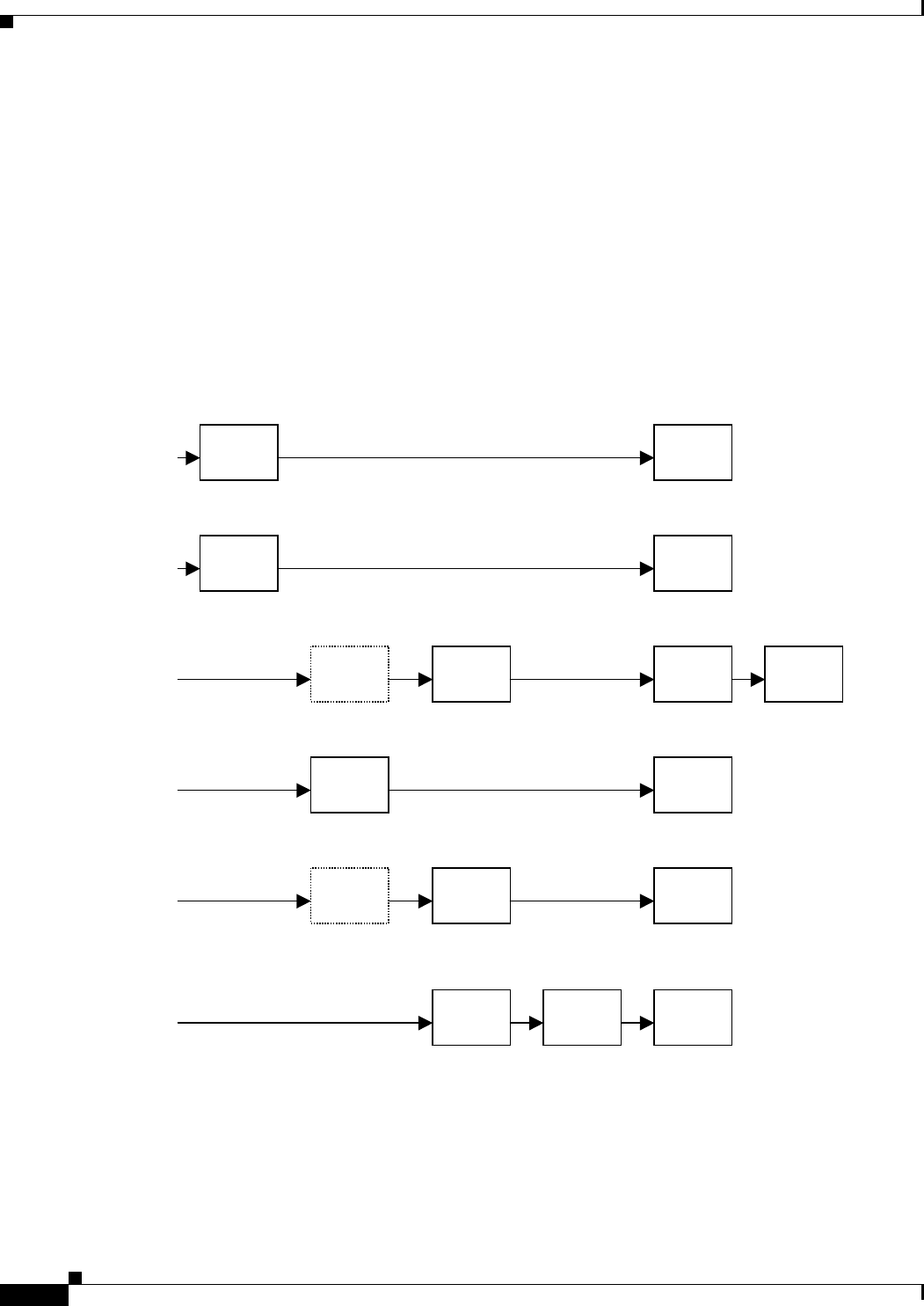
•On Hook Caller ID Associated with Ringing — This type of Caller ID is used for incoming calls
when the attached phone is on hook. See the following figure (a) – (c). All CID methods can be
applied for this type of CID.
•On Hook Caller ID Not Associated with Ringing — This feature is used to send VMWI signal to the
phone to turn the message waiting light on and off (see Figure 1 (d) and (e)). This is available only
for FSK-based CID methods: (Bellcore, ETSI FSK, and ETSI FSK With PR).
•Off Hook Caller ID — This is used to delivery caller-id on incoming calls when the attached phone
is off hook (see the following figure). This can be call waiting caller ID (CIDCW) or to notify the
user that the far end party identity has changed or updated (such as due to a call transfer). This is
available only for FSK-based CID methods: (Bellcore, ETSI FSK, and ETSI FSK With PR).
Optimize Fax Completion Rates
Issues can occur with fax transmissions over IP networks, even with the T.38 standard, which is
supported by the WRP500. You can adjust several settings on your WRP500 to optimize your fax
completion rates.
Polarity
Reversal
First
Ring
CAS
(DTAS)
DTMF/
FSK
Polarity
Reversal
CAS
(DTAS) FSK
CAS
(DTAS)
Wait For
ACK FSK
First
Ring FSK
OSI FSK
a) Bellcore/ETSI Onhook Post-Ring FSK
d) Bellcore Onhook FSK w/o Ring
f) Bellcore/ETSI Offhook FSK
c) ETSI Onhook Pre-Ring FSK/DTMF
e) ETSI Onhook FSK w/o Ring
DTMF
b) ETSI Onhook Post-Ring DTMF
First
Ring

REVIEW DRAFT #1—CISCO CONFIDENTIAL
3-9
Cisco WRP500 Administration Guide
Chapter 3 Configure Voice Services
Optimize Fax Completion Rates
Note Only T.38 Fax is supported. The WRP500 supports one connection.
Step 1 Ensure that you have enough bandwidth for the uplink and the downlink.
• For G.711 fallback, it is recommend to have approximately 100Kbps.
• For T.38, allocate at least 50 kbps.
Step 2 To optimize G.711 fallback fax completion rates, set the following on the Line tab of your ATA device:
•Call Waiting Serv: no
•Three Way Call Serv: no
•Preferred Codec: G.711
•Use pref. codec only: yes
Step 3 If you are using a Cisco media gateway for PSTN termination, disable T.38 (fax relay) and enable fax
using modem passthrough.
For example:
modem passthrough nse payload-type 110 codec g711ulaw
fax rate disable
fax protocol pass-through g711ulaw
Step 4 Enable T.38 fax on the WRP500 by configuring the following parameter on the Line tab for the FXS port
to which the FAX machine is connected:
FAX_Enable T38: Yes
Note If a T.38 call cannot be set-up, then the call automatically reverts to G.711 fallback.
Step 5 If you are using a Cisco media gateway use the following settings:
Make sure the Cisco gateway is correctly configured for T.38 with the SPA dial peer. For example:
fax protocol T38
fax rate voice
fax-relay ecm disable
fax nsf 000000
no vad
Fax Troubleshooting
If you have problems sending or receiving faxes, complete the following steps:
Step 1 Verify that your fax machine is set to a speed between 7200 and 14400.
Step 2 Send a test fax in a controlled environment between two ATAs.
Step 3 Determine the success rate.

REVIEW DRAFT #1—CISCO CONFIDENTIAL
3-10
Cisco WRP500 Administration Guide
Chapter 3 Configure Voice Services
Silence Suppression and Comfort Noise Generation
Step 4 Monitor the network and record the following statistics:
•Jitter
•Loss
•Delay
Step 5 If faxes fail consistently, capture a copy of the voice settings by selecting Save As > Web page,
complete from the administration web server page. You can send this configuration file to Technical
Support.
STEP 6 Enable and capture the debug log. For instructions, refer to Appendix C, “Troubleshooting.”
Note You may also capture data using a sniffer trace.
Step 7 Identify the type of fax machine connected to the ATA device.
Step 8 Contact technical support:
• If you are an end user of VoIP products, contact the reseller or Internet telephony service
provider (ITSP) that supplied the equipment.
• If you are an authorized Cisco partner, contact Cisco technical support.
Silence Suppression and Comfort Noise Generation
Voice Activity Detection (VAD) with Silence Suppression is a means of increasing the number of calls
supported by the network by reducing the required bandwidth for a single call. VAD uses a sophisticated
algorithm to distinguish between speech and non-speech signals. Based on the current and past statistics,
the VAD algorithm decides whether or not speech is present. If the VAD algorithm decides speech is not
present, the silence suppression and comfort noise generation is activated. This is accomplished by
removing and not transmitting the natural silence that occurs in normal two-way connection. The IP
bandwidth is used only when someone is speaking. During the silent periods of a telephone call,
additional bandwidth is available for other voice calls or data traffic because the silence packets are not
being transmitted across the network.
Comfort Noise Generation provides artificially-generated background white noise (sounds), designed to
reassure callers that their calls are still connected during silent periods. If Comfort Noise Generation is
not used, the caller may think the call has been disconnected because of the “dead silence” periods
created by the VAD and Silence Suppression feature.
Silence suppression is configured in the Line and PSTN Line tabs. See Appendix B, “Data Fields.”
Configure Dial Plans
Dial plans determine how the digits are interpreted and transmitted. They also determine whether the
dialed number is accepted or rejected. You can use a dial plan to facilitate dialing or to block certain
types of calls such as long distance or international.

REVIEW DRAFT #1—CISCO CONFIDENTIAL
3-11
Cisco WRP500 Administration Guide
Chapter 3 Configure Voice Services
Configure Dial Plans
This section includes information that you need to understand dial plans, as well as procedures for
configuring your own dial plans. This section includes the following topics:
•“About Dial Plans,” on page 11
•“Edit Dial Plans,” on page 17
About Dial Plans
This section provides information to help you understand how dial plans are implemented.
Refer to the following topics:
•“Digit Sequences,” on page 11
•“Digit Sequence Examples,” on page 12
•“Acceptance and Transmission the Dialed Digits,” on page 14
•“Dial Plan Timer (Off-Hook Timer),” on page 15
•“Interdigit Long Timer (Incomplete Entry Timer),” on page 15
•“Interdigit Short Timer (Complete Entry Timer),” on page 16
Digit Sequences
A dial plan contains a series of digit sequences, separated by the | character. The entire collection
of sequences is enclosed within parentheses. Each digit sequence within the dial plan consists of a
series of elements, which are individually matched to the keys that the user presses.
Note White space is ignored, but may be used for readability.
Digit Sequence Function
0 1 2 3 4 5 6 7 8 9 0 * # Enter any of these characters to represent a key that the
user must press on the phone keypad.
xEnter x to represent any character on the phone keypad.
[sequence] Enter characters within square brackets to create a list of
accepted key presses. The user can press any one of the
keys in the list.
• Numeric range
For example, you would enter [2-9] to allow the user to
press any one digit from 2 through 9.
• Numeric range with other characters
For example, you would enter [35-8*] to allow the user to
press 3, 5, 6, 7, 8, or *.

REVIEW DRAFT #1—CISCO CONFIDENTIAL
3-12
Cisco WRP500 Administration Guide
Chapter 3 Configure Voice Services
Configure Dial Plans
Digit Sequence Examples
The following examples show digit sequences that you can enter in a dial plan.
In a complete dial plan entry, sequences are separated by a pipe character (|), and the entire set of
sequences is enclosed within parentheses.
.
(period)
Enter a period for element repetition. The dial plan
accepts 0 or more entries of the digit. For example, 01.
allows users to enter 0, 01, 011, 0111, and so on.
<dialed:substituted> Use this format to indicate that certain dialed digits are
replaced by other characters when the sequence is
transmitted. The dialed digits can be zero or more
characters.
EXAMPLE 1: <8:1650>xxxxxxx
When the user presses 8 followed by a seven-digit
number, the system automatically replaces the dialed 8
with 1650. If the user dials 85550112, the system
transmits 16505550112.
EXAMPLE 2: <:1>xxxxxxxxxx
In this example, no digits are replaced. When the user
enters a 10-digit string of numbers, the number 1 is added
at the beginning of the sequence. If the user dials
9725550112, the system transmits 19725550112
,
(comma)
Enter a comma between digits to play an “outside line”
dial tone after a user-entered sequence.
EXAMPLE: 9, 1xxxxxxxxxx
An “outside line” dial tone is sounded after the user
presses 9, and the tone continues until the user presses 1.
!
(exclamation point)
Enter an exclamation point to prohibit a dial sequence
pattern.
EXAMPLE: 1900xxxxxxx!
The system rejects any 11-digit sequence that begins with
1900.
*xx Enter an asterisk to allow the user to enter a 2-digit star code.
S0 or L0 Enter S0 to reduce the short inter-digit timer to 0 seconds, or
enter L0 to reduce the long inter-digit timer to 0 seconds.
Digit Sequence Function

REVIEW DRAFT #1—CISCO CONFIDENTIAL
3-13
Cisco WRP500 Administration Guide
Chapter 3 Configure Voice Services
Configure Dial Plans
EXAMPLE: ( [1-8]xx | 9, xxxxxxx | 9, <:1>[2-9]xxxxxxxxx | 8, <:1212>xxxxxxx | 9, 1 [2-9] xxxxxxxxx
| 9, 1 900 xxxxxxx ! | 9, 011xxxxxx. | 0 | [49]11 )
• Extensions on your system
EXAMPLE: ( [1-8]xx | 9, xxxxxxx | 9, <:1>[2-9]xxxxxxxxx | 8, <:1212>xxxxxxx | 9, 1 [2-9]
xxxxxxxxx | 9, 1 900 xxxxxxx ! | 9, 011xxxxxx. | 0 | [49]11 )
[1-8]xx Allows a user dial any three-digit number that starts with the digits 1 through 8. If your
system uses four-digit extensions, you would instead enter the following string: [1-8]xxx
• Local dialing with seven-digit number
EXAMPLE: ( [1-8]xx | 9, xxxxxxx | 9, <:1>[2-9]xxxxxxxxx | 8, <:1212>xxxxxxx | 9, 1 [2-9]
xxxxxxxxx | 9, 1 900 xxxxxxx ! | 9, 011xxxxxx. | 0 | [49]111)
9, xxxxxxx After a user presses 9, an external dial tone sounds. The user can enter any seven-digit
number, as in a local call.
• Local dialing with 3-digit area code and a 7-digit local number
EXAMPLE: ( [1-8]xx | 9, xxxxxxx | 9, <:1>[2-9]xxxxxxxxx | 8, <:1212>xxxxxxx | 9, 1 [2-9]
xxxxxxxxx | 9, 1 900 xxxxxxx ! | 9, 011xxxxxx. | 0 | [49]11 )
9, <:1>[2-9]xxxxxxxxx This example is useful where a local area code is required. After a user
presses 9, an external dial tone sounds. The user must enter a 10-digit number that begins with a
digit 2 through 9. The system automatically inserts the 1 prefix before transmitting the number to
the carrier.
• Local dialing with an automatically inserted 3-digit area code
EXAMPLE: ( [1-8]xx | 9, xxxxxxx | 9, <:1>[2-9]xxxxxxxxx | 8, <:1212>xxxxxxx | 9, 1 [2-9]
xxxxxxxxx | 9, 1 900 xxxxxxx ! | 9, 011xxxxxx. | 0 | [49]11 )
8, <:1212>xxxxxxx This is example is useful where a local area code is required by the carrier but
the majority of calls go to one area code. After the user presses 8, an external dial tone sounds. The
user can enter any seven-digit number. The system automatically inserts the 1 prefix and the 212
area code before transmitting the number to the carrier.
• U.S. long distance dialing
EXAMPLE: ( [1-8]xx | 9, xxxxxxx | 9, <:1>[2-9]xxxxxxxxx | 8, <:1212>xxxxxxx | 9, 1 [2-9]
xxxxxxxxx | 9, 1 900 xxxxxxx ! | 9, 011xxxxxx. | 0 | [49]11 )
9, 1 [2-9] xxxxxxxxx After the user presses 9, an external dial tone sounds. The user can enter any
11-digit number that starts with 1 and is followed by a digit 2 through 9.
• Blocked number
EXAMPLE: ( [1-8]xx | 9, xxxxxxx | 9, <:1>[2-9]xxxxxxxxx | 8, <:1212>xxxxxxx | 9, 1 [2-9]
xxxxxxxxx | 9, 1 900 xxxxxxx ! | 9, 011xxxxxx. | 0 | [49]11 )
9, 1 900 xxxxxxx ! This digit sequence is useful if you want to prevent users from dialing numbers
that are associated with high tolls or inappropriate content, such as 1-900 numbers in the U.S.. After
the user press 9, an external dial tone sounds. If the user enters an 11-digit number that starts with
the digits 1900, the call is rejected.
• U.S. international dialing

REVIEW DRAFT #1—CISCO CONFIDENTIAL
3-14
Cisco WRP500 Administration Guide
Chapter 3 Configure Voice Services
Configure Dial Plans
EXAMPLE: ( [1-8]xx | 9, xxxxxxx | 9, <:1>[2-9]xxxxxxxxx | 8, <:1212>xxxxxxx | 9, 1 [2-9]
xxxxxxxxx | 9, 1 900 xxxxxxx ! | 9, 011xxxxxx. | 0 | [49]11 )
9, 011xxxxxx. After the user presses 9, an external dial tone sounds. The user can enter any number
that starts with 011, as in an international call from the U.S.
• Informational numbers
EXAMPLE: ( [1-8]xx | 9, xxxxxxx | 9, <:1>[2-9]xxxxxxxxx | 8, <:1212>xxxxxxx | 9, 1 [2-9]
xxxxxxxxx | 9, 1 900 xxxxxxx ! | 9, 011xxxxxx. | 0 | [49]11 )
0 | [49]11 This example includes two digit sequences, separated by the pipe character. The first
sequence allows a user to dial 0 for an operator. The second sequence allows the user to enter 411
for local information or 911 for emergency services.
Acceptance and Transmission the Dialed Digits
When a user dials a series of digits, each sequence in the dial plan is tested as a possible match. The
matching sequences form a set of candidate digit sequences. As more digits are entered by the user, the
set of candidates diminishes until only one or none are valid. When a terminating event occurs, the
WRP500 either accepts the user-dialed sequence and initiates a call, or else rejects the sequence as
invalid. The user hears the reorder (fast busy) tone if the dialed sequence is invalid.
The following table explains how terminating events are processed.
Terminating Event Processing
The dialed digits do not match any
sequence in the dial plan.
The number is rejected.
The dialed digits exactly match one
sequence in the dial plan.
• If the sequence is allowed by the dial plan, the
number is accepted and is transmitted according to
the dial plan.
• If the sequence is blocked by the dial plan, the
number is rejected.
A timeout occurs. The number is rejected if the dialed digits are not
matched to a digit sequence in the dial plan within
the time specified by the applicable interdigit timer.
• The Interdigit Long Timer applies when the dialed
digits do not match any digit sequence in the dial
plan. The default value is 10 seconds.
• The Interdigit Short Timer applies when the dialed
digits match one or more candidate sequences in the
dial plan. The default value is 3 seconds.
The user presses the # key or the
dial softkey on the phone display.
• If the sequence is complete and is allowed by the dial
plan, the number is accepted and is transmitted
according to the dial plan.
• If the sequence is incomplete or is blocked by the dial
plan, the number is rejected.

REVIEW DRAFT #1—CISCO CONFIDENTIAL
3-15
Cisco WRP500 Administration Guide
Chapter 3 Configure Voice Services
Configure Dial Plans
Dial Plan Timer (Off-Hook Timer)
You can think of the Dial Plan Timer as “the off-hook timer.” This timer starts counting when the phone
goes off hook. If no digits are dialed within the specified number of seconds, the timer expires and the
null entry is evaluated. Unless you have a special dial plan string to allow a null entry, the call is rejected.
The default value is 5.
Syntax for the Dial Plan Timer
SYNTAX: (Ps<:n> | dial plan )
•s: The number of seconds; if no number is entered after P, the default timer of 5 seconds
applies.
•n: (optional): The number to transmit automatically when the timer expires; you can enter an
extension number or a DID number. No wildcard characters are allowed because the number
will be transmitted as shown. If you omit the number substitution, <:n>, then the user hears a
reorder (fast busy) tone after the specified number of seconds.
Examples for the Dial Plan Timer
• Allow more time for users to start dialing after taking a phone off hook.
EXAMPLE: (P9 | (9,8<:1408>[2-9]xxxxxx | 9,8,1[2-9]xxxxxxxxx | 9,8,011xx. | 9,8,xx.|[1-8]xx)
P9 After taking a phone off hook, a user has 9 seconds to begin dialing. If no digits are pressed
within 9 seconds, the user hears a reorder (fast busy) tone. By setting a longer timer, you allow more
time for users to enter the digits.
• Create a hotline for all sequences on the System Dial Plan
EXAMPLE: (P9<:23> | (9,8<:1408>[2-9]xxxxxx | 9,8,1[2-9]xxxxxxxxx | 9,8,011xx. |
9,8,xx.|[1-8]xx)
P9<:23> After taking the phone off hook, a user has 9 seconds to begin dialing. If no digits are
pressed within 9 seconds, the call is transmitted automatically to extension 23.
• Create a hotline on a line button for an extension
EXAMPLE: ( P0 <:1000>)
With the timer set to 0 seconds, the call is transmitted automatically to the specified extension when
the phone goes off hook. Enter this sequence in the Phone Dial Plan for Ext 2 or higher on a client
station.
Interdigit Long Timer (Incomplete Entry Timer)
You can think of this timer as the “incomplete entry” timer. This timer measures the interval between
dialed digits. It applies as long as the dialed digits do not match any digit sequences in the dial plan.
Unless the user enters another digit within the specified number of seconds, the entry is evaluated as
incomplete, and the call is rejected. The default value is 10 seconds.

REVIEW DRAFT #1—CISCO CONFIDENTIAL
3-16
Cisco WRP500 Administration Guide
Chapter 3 Configure Voice Services
Configure Dial Plans
Note This section explains how to edit a timer as part of a dial plan. Alternatively, you can modify the Control
Timer that controls the default interdigit timers for all calls. See “Reset the Control Timers,” on page 17.
Syntax for the Interdigit Long Timer
SYNTAX: L:s, ( dial plan )
•s: The number of seconds; if no number is entered after L:, the default timer of 5 seconds
applies.
• Note that the timer sequence appears to the left of the initial parenthesis for the dial plan.
Example for the Interdigit Long Timer
EXAMPLE: L:15, (9,8<:1408>[2-9]xxxxxx | 9,8,1[2-9]xxxxxxxxx | 9,8,011xx. | 9,8,xx.|[1-8]xx)
L:15, This dial plan allows the user to pause for up to 15 seconds between digits before the Interdigit
Long Timer expires. This setting is especially helpful to users such as sales people, who are reading the
numbers from business cards and other printed materials while dialing.
Interdigit Short Timer (Complete Entry Timer)
You can think of this timer as the “complete entry” timer. This timer measures the interval between
dialed digits. It applies when the dialed digits match at least one digit sequence in the dial plan. Unless
the user enters another digit within the specified number of seconds, the entry is evaluated. If it is valid,
the call proceeds. If it is invalid, the call is rejected. The default value is 3 seconds.
Syntax for the Interdigit Short Timer
•SYNTAX 1: S:s, ( dial plan )
Use this syntax to apply the new setting to the entire dial plan within the parentheses.
•SYNTAX 2: sequence Ss
Use this syntax to apply the new setting to a particular dialing sequence.
s: The number of seconds; if no number is entered after S, the default timer of 5 seconds applies.
Examples for the Interdigit Short Timer
• Set the timer for the entire dial plan.
EXAMPLE: S:6, (9,8<:1408>[2-9]xxxxxx | 9,8,1[2-9]xxxxxxxxx | 9,8,011xx. | 9,8,xx.|[1-8]xx)
S:6, While entering a number with the phone off hook, a user can pause for up to 15 seconds between
digits before the Interdigit Short Timer expires. This setting is especially helpful to users such as
sales people, who are reading the numbers from business cards and other printed materials while
dialing.
• Set an instant timer for a particular sequence within the dial plan.
EXAMPLE: (9,8<:1408>[2-9]xxxxxx | 9,8,1[2-9]xxxxxxxxxS0 | 9,8,011xx. | 9,8,xx.|[1-8]xx)

REVIEW DRAFT #1—CISCO CONFIDENTIAL
3-17
Cisco WRP500 Administration Guide
Chapter 3 Configure Voice Services
Configure Dial Plans
9,8,1[2-9]xxxxxxxxxS0 With the timer set to 0, the call is transmitted automatically when the user
dials the final digit in the sequence.
Edit Dial Plans
You can edit dial plans and can modify the control timers.
Enter the Line Interface Dial Plan
This dial plan is used to strip steering digits from a dialed number before it is transmitted out to the
carrier.
Step 1 Start Internet Explorer, connect to the Configuration Utility, choose Voice > Admin Login. If prompted,
enter the administrative login provided by the Service Provider. (The default username and password are
both admin.)rovided by your Service Provider.
Step 2 Under the Voice menu, click Line 1 or Line 2, depending on the line interface that you want to configure.
Step 3 Scroll down to the Dial Plan section.
Step 4 Enter the digit sequences in the Dial Plan field. For more information, see “About Dial Plans,” on
page 11.
Step 5 Click Submit.
Reset the Control Timers
You can use the following procedure to reset the default timer settings for all calls.
Note If you need to edit a timer setting only for a particular digit sequence or type of call, you can edit the
dial plan. See “About Dial Plans,” on page 11.
Step 1 Start Internet Explorer, connect to the Configuration Utility, choose Voice > Admin Login. If prompted,
enter the administrative login provided by the Service Provider. (The default username and password are
both admin.)rovided by your Service Provider.
Step 2 Under the Voice menu, click Regional.
Step 3 Scroll down to the Control Timer Values section.
Step 4 Enter the desired values in the Interdigit Long Timer field and the Interdigit Short Timer field. Refer to
the definitions at the beginning of this section.

REVIEW DRAFT #1—CISCO CONFIDENTIAL
3-18
Cisco WRP500 Administration Guide
Chapter 3 Configure Voice Services
Secure Call Implementation
Secure Call Implementation
This section describes secure call implementation with the WRP500 . It includes the following topics:
•“Enable Secure Calls” section on page 3-18
Note This is an advanced topic meant for experience installers. Also see the Provisioning Guide at the
following URL:
www.cisco.com/en/US/docs/voice_ip_comm/csbpvga/ata/provisioning/guide/Cisco_Small_Business_I
P_Telephony_Provisioning_Guide.pdf
Enable Secure Calls
WRP500 does not support establishing secure call by "mini certificate" as WRP400 did. The only way
to enable a secure call requires use of SRTP, while the SRTP key parameters are transferred in SIP
messages that are encrypted by TLS.
To enable SRTP on Line 1:
•-Voice > Line 1 > Secure Call Serv, set to Yes
•-Voice > User 1 > Secure Call Setting, set to Yes
To enable SIP over TLS on Line:
•-Voice > Line 1 > SIP Tranport, set to TLS

A-1
Cisco WRP500 Administration Guide
APPENDIX
REVIEW DRAFT #1—CISCO CONFIDENTIAL
A
Advanced Voice Fields
This appendix describes the Advanced settings that are available after you log in as administrator.
Note For information about the other pages in the Configuration Utility, see the ____________e.
After you click the Voice tab, you can choose the following pages:
•“Info page,” on page 1
•“System page,” on page 5
•“SIP page,” on page 6
•“Regional page,” on page 13
•“Line page,” on page 28
•“User page,” on page 41
Info page
You can use the Voice tab > Info page to view information about the WRP500. This page includes
the following sections:
•“Product Information section,” on page 2
•“System Status section,” on page 2
•“Line Status section,” on page 3
Note The fields on the Info page are read-only and cannot be edited.

REVIEW DRAFT #1—CISCO CONFIDENTIAL
A-2
Cisco WRP500 Administration Guide
Appendix A Advanced Voice Fields
Info page
Voice tab > Info page >
Product Information section
Voice tab > Info page >
System Status section
Product Name Model number/name.
Serial Number Serial number.
Software Version Software version number.
Hardware Version Hardware version number.
MAC Address MAC address.
Client Certificate Status of the client certificate, which can indicate if the WRP500
has been authorized by your ITSP.
Customization For a Remote Configuration (RC) unit, this field indicates whether
the unit has been customized or not. Pending indicates a new RC
unit that is ready for provisioning. If the unit has already retrieved
its customized profile, this field displays the name of the company
that provisioned the unit.
Voice Module Version Voice module number
Current Time Current date and time of the system; for example, 10/3/2003
16:43:00.
Elapsed Time Total time elapsed since the last reboot of the system; for example,
25 days and 18:12:36.
RTP Packets Sent Total number of RTP packets sent (including redundant packets).
RTP Bytes Sent Total number of RTP bytes sent.
RTP Packets Recv Total number of RTP packets received (including redundant
packets).
RTP Bytes Recv Total number of RTP bytes received.
SIP Messages Sent Total number of SIP messages sent (including retransmissions).
SIP Bytes Sent Total number of bytes of SIP messages sent (including
retransmissions).
SIP Messages Recv Total number of SIP messages received (including retransmissions).

REVIEW DRAFT #1—CISCO CONFIDENTIAL
A-3
Cisco WRP500 Administration Guide
Appendix A Advanced Voice Fields
Info page
Voice tab > Info page >
Line Status section
SIP Bytes Recv Total number of bytes of SIP messages received (including
retransmissions).
External IP External IP address used for NAT mapping.
Hook State Hook state of the FXO port. Options are either On or Off.
Registration State Indicates if the line has registered with the SIP proxy.
Last Registration At Last date and time the line was registered.
Next Registration In Number of seconds before the next registration renewal.
Message Waiting Indicates whether you have new voice mail waiting. Options are
either Yes or No. The value automatically is set to Yes when a
message is received. You also can clear or set the flag manually.
Setting this value to Yes can activate stutter tone and VMWI signal.
This parameter is stored in long term memory and survives after
reboot or power cycle.
Call Back Active Indicates whether a call back request is in progress. Options are
either Yes or No.
Last Called Number The last number called from the FXO Line.
Last Caller Number Number of the last caller.
Mapped SIP Port Port number of the SIP port mapped by NAT.
Call 1 and 2 State May take one of the following values:
•Idle
• Collecting PSTN Pin
• Invalid PSTN PIN
• PSTN Caller Accepted
• Connected to PSTN
Call 1 and 2 Tone Type of tone used by the call.
Call 1 and 2 Encoder Codec used for encoding.
Call 1 and 2 Decoder Codec used for decoding.
Call 1 and 2 FAX Status of the fax pass-through mode.

REVIEW DRAFT #1—CISCO CONFIDENTIAL
A-4
Cisco WRP500 Administration Guide
Appendix A Advanced Voice Fields
Info page
Call 1 and 2 Type Direction of the call. May take one of the following values:
• PSTN Gateway Call = VoIP-To-PSTN Call
• VoIP Gateway Call = PSTN-To-VoIP Call
• PSTN To Line 1 = PSTN call ring through and answered by Line 1
• Line 1 Forward to PSTN Gateway = VoIP calls Line 1 then forwarded
to PSTN GW
• Line 1 Forward to PSTN Number =VoIP calls Line 1 then forwarded
to PSTN number
• Line 1 To PSTN Gateway
• Line 1 Fallback To PSTN Gateway
Call 1 and 2 Remote
Hold
Indicates whether the far end has placed the call on hold.
Call 1 and 2 Callback Indicates whether the call was triggered by a call back request.
Call 1 and 2 Peer
Name
Name of the internal phone.
Call 1 and 2 Peer
Phone
Phone number of the internal phone.
Call 1 and 2 Call
Duration
Duration of the call.
Call 1 and 2 Packets
Sent
Number of packets sent.
Call 1 and 2 Packets
Recv
Number of packets received.
Call 1 and 2 Bytes
Sent
Number of bytes sent.
Call 1 and 2 Bytes
Recv
Number of bytes received.
Call 1 and 2 Decode
Latency
Number of milliseconds for decoder latency.
Call 1 and 2 Jitter Number of milliseconds for receiver jitter.
Call 1 and 2 Packets
Lost
Number of packets lost.
Call 1 and 2 Packet
Error
Number of invalid packets received.
Call 1 and 2 Mapped
RTP Port
The port mapped for Real Time Protocol traffic for Call 1/2.
Call 1 and 2 Media
Loopback
Media loopback is used to quantitatively and qualitatively measure
the voice quality experienced by the end user.

REVIEW DRAFT #1—CISCO CONFIDENTIAL
A-5
Cisco WRP500 Administration Guide
Appendix A Advanced Voice Fields
System page
System page
You can use the Voice tab > System page to configure your system and network connections. This
page includes the following sections:
•“System Configuration section” section on page A-5
•“Miscellaneous Settings section” section on page A-5
Voice tab > System page >
System Configuration section
Voice tab > System page >
Miscellaneous Settings section
Restricted Access
Domains
This feature is used when implementing software customization.
IVR Admin Passwd Password for entering IVR menu.
Syslog Server Specifies the IP address of the syslog server.
Debug Server Specifies the IP address of the debug server, which logs debug
information. The level of detailed output depends on the debug
level parameter setting.
Debug Level Determines the level of debug information that is generated. Select
0, 1, 2, or 3 from the drop-down menu. The higher the debug level,
the more debug information is generated.
The default is 0, which indicates that no debug information is
generated.
Debug Option Specifies what debug information is expected. Generally can be set
to dbg_all.

REVIEW DRAFT #1—CISCO CONFIDENTIAL
A-6
Cisco WRP500 Administration Guide
Appendix A Advanced Voice Fields
SIP page
SIP page
You can use the Vo ice ta b > S I P page to configure the SIP settings. This page includes the following
sections:
•“SIP Parameters section” section on page A-6
•“SIP Timer Values (sec) section” section on page A-8
•“Response Status Code Handling section” section on page A-9
•“RTP Parameters section” section on page A-10
•“SDP Payload Types section” section on page A-10
•“NAT Support Parameters section” section on page A-11
Voice tab > SIP page >
SIP Parameters section
Max Forward SIP Max Forward value, which can range from 1 to 255.
The default is 70.
Max Redirection Number of times an invite can be redirected to avoid an infinite
loop.
The default is 5.
Max Auth Maximum number of times (from 0 to 255) a request may be
challenged.
The default is 2.
SIP User Agent Name User-Agent header used in outbound requests.
The default is $VERSION. If empty, the header is not included.
Macro expansion of $A to $D corresponding to GPP_A to GPP_D
allowed.
SIP Server Name Server header used in responses to inbound responses.
The default is $VERSION.
SIP Reg User Agent
Name
User-Agent name to be used in a REGISTER request. If this value
is not specified, the SIP User Agent Name parameter is also used for
the REGISTER request.
The default is blank.
SIP Accept Language Accept-Language header used. There is no default (this indicates
the WRP500 does not include this header). If empty, the header is
not included.

REVIEW DRAFT #1—CISCO CONFIDENTIAL
A-7
Cisco WRP500 Administration Guide
Appendix A Advanced Voice Fields
SIP page
DTMF Relay MIME
Type
MIME Type used in a SIP INFO message to signal a DTMF event.
The default is application/dtmf-relay.
Remove Last Reg Lets you remove the last registration before registering a new one if
the value is different. Select yes or no from the drop-down menu.
The default is no.
Use Compact Header Lets you use compact SIP headers in outbound SIP messages.
Select yes or no from the drop-down menu. If set to yes, the
WRP500 uses compact SIP headers in outbound SIP messages. If
set to no, the WRP500 uses normal SIP headers. If inbound SIP
requests contain compact headers, the WRP500 reuses the same
compact headers when generating the response regardless the
settings of the Use Compact Header parameter. If inbound SIP
requests contain normal headers, the WRP500 substitutes those
headers with compact headers (if defined by RFC 261) if Use
Compact Header parameter is set to yes.
The default is no.
Escape Display Name Lets you keep the Display Name private. Select yes if you want the
WRP500 to enclose the string (configured in the Display Name) in
a pair of double quotes for outbound SIP messages. Any
occurrences of or \ in the string is escaped with \ and \\ inside the
pair of double quotes. Otherwise, select no.
The default is no.
RFC 2543 Call Hold Configures the type of call hold: a:sendonly or 0.0.0.0.
The default is no; do not use the 0.0.0.0 syntax in a HOLD SDP; use
the a:sendonly syntax.
Mark All AVT Packets If set to yes, all AVT tone packets (encoded for redundancy) have
the marker bit set. If set to no, only the first packet has the marker
bit set for each DTMF event.
The default is yes.
SIP TCP Port Min Specifies the lowest TCP port number that can be used for SIP
sessions.
SIP TCP Port Max Specifies the highest TCP port number that can be used for SIP
sessions.

REVIEW DRAFT #1—CISCO CONFIDENTIAL
A-8
Cisco WRP500 Administration Guide
Appendix A Advanced Voice Fields
SIP page
Voice tab > SIP page >
SIP Timer Values (sec) section
SIP T1 RFC 3261 T1 value (RTT estimate), which can range from 0 to 64
seconds.
The default is.5.
SIP T2 RFC 3261 T2 value (maximum retransmit interval for non-INVITE
requests and INVITE responses), which can range from 0 to 64
seconds.
The default is 4.
SIP T4 RFC 3261 T4 value (maximum duration a message remains in the
network), which can range from 0 to 64 seconds.
The default is 5.
SIP Timer B INVITE time-out value, which can range from 0 to 64 seconds.
The default is 32.
SIP Timer F Non-INVITE time-out value, which can range from 0 to 64
seconds.
The default is 32.
SIP Timer H INVITE final response, time-out value, which can range from 0 to
64 seconds.
The default is 32.
SIP Timer D ACK hang-around time, which can range from 0 to 64 seconds.
The default is 32.
SIP Timer J Non-INVITE response hang-around time, which can range from 0
to 64 seconds.
The default is 32.
INVITE Expires INVITE request Expires header value. If you enter 0, the Expires
header is not included in the request.
The default is 240. Range: 0–(231–1).
ReINVITE Expires ReINVITE request Expires header value. If you enter 0, the Expires
header is not included in the request.
The default is 30. Range: 0–(231–1).

REVIEW DRAFT #1—CISCO CONFIDENTIAL
A-9
Cisco WRP500 Administration Guide
Appendix A Advanced Voice Fields
SIP page
Voice tab > SIP page >
Response Status Code Handling section
Reg Min Expires Minimum registration expiration time allowed from the proxy in the
Expires header or as a Contact header parameter. If the proxy
returns a value less than this setting, the minimum value is used.
The default is 1.
Reg Max Expires Maximum registration expiration time allowed from the proxy in
the Min-Expires header. If the value is larger than this setting, the
maximum value is used.
The default is 7200.
Reg Retry Intvl Interval to wait before the WRP500 retries registration after failing
during the last registration.
The default is 30.
Reg Retry Long Intvl When registration fails with a SIP response code that does not
match
Retry Reg RSC, the WRP500 waits for the specified length of time
before retrying. If this interval is 0, the WRP500 stops trying. This
value should be much larger than the Reg Retry Intvl value, which
should not be 0.
The default is 1200.
SIT1 RSC SIP response status code for the appropriate Special Information
Tone (SIT). For example, if you set the SIT1 RSC to 404, when the
user makes a call and a failure code of 404 is returned, the SIT1
tone is played. Reorder or Busy tone is played by default for all
unsuccessful response status code for SIT 1 RSC through SIT 4
RSC.
SIT2 RSC SIP response status code to INVITE on which to play the SIT2
Tone.
SIT3 RSC SIP response status code to INVITE on which to play the SIT3
Tone.
SIT4 RSC SIP response status code to INVITE on which to play the SIT4
Tone.
Try Backup RSC SIP response code that retries a backup server for the current
request.

REVIEW DRAFT #1—CISCO CONFIDENTIAL
A-10
Cisco WRP500 Administration Guide
Appendix A Advanced Voice Fields
SIP page
Voice tab > SIP page >
RTP Parameters section
Voice tab > SIP page >
SDP Payload Types section
Retry Reg RSC Interval to wait before the WRP500 retries registration after failing
during the last registration.
The default is 30.
RTP Port Min Minimum port number for RTP transmission and reception. The RTP
Port Min and RTP Port Max parameters should define a range that
contains at least 4 even number ports, such as 100 – 106.
The default is 16384.
RTP Port Max Maximum port number for RTP transmission and reception.
The default is 16482.
RTP Packet Size Packet size in seconds, which can range from 0.01 to 0.16. Valid
values must be a multiple of 0.01 seconds.
The default is 0.030.
Stats In BYE Determines whether the WRP500 includes the P-RTP-Stat header
or response to a BYE message. The header contains the RTP
statistics of the current call. Select yes or no from the drop-down
menu. The format of the P-RTP-Stat header is:
P-RTP-State: PS=<packets sent>,OS=<octets sent>,PR=<packets
received>,OR=<octets received>,PL=<packets lost>,JI=<jitter in
ms>,LA=<delay in ms>,DU=<call duration in
s>,EN=<encoder>,DE=<decoder>.
The default is no.
NSE Dynamic
Payload
NSE dynamic payload type. The valid range is 96-127.
The default is 100.
AV T Dy n a m i c
Payload
AVT dynamic payload type. The valid range is 96-127.
The default is 101.

REVIEW DRAFT #1—CISCO CONFIDENTIAL
A-11
Cisco WRP500 Administration Guide
Appendix A Advanced Voice Fields
SIP page
Voice tab > SIP page >
NAT Support Parameters section
INFOREQ Dynamic
Payload
INFOREQ dynamic payload type.
There is no default.
NSE Codec Name NSE codec name used in SDP.
The default is NSE.
AVT Codec Name AVT codec name used in SDP.
The default is telephone-event.
G711u Codec Name G.711u codec name used in SDP.
The default is computerMU.
G711a Codec Name G.711a codec name used in SDP.
The default is computerMA.
G729a Codec Name G.729a codec name used in SDP.
The default is G729a.
G729b Codec Name G.729b codec name used in SDP.
The default is G729ab.
G723 Codec Name G.723 codec name used in SDP.
The default is G723.
EncapRTP Codec
Name
EncapRTP codec name used in SDP.
The default is EncapRTP.
EncapRTP Dynamic
Payload
EncapRTP dynamic payload type.
Handle VIA received If you select yes, the WRP500 processes the received parameter in
the VIA header (this value is inserted by the server in a response to
anyone of its requests). If you select no, the parameter is ignored.
Select yes or no from the drop-down menu.
The default is no.

REVIEW DRAFT #1—CISCO CONFIDENTIAL
A-12
Cisco WRP500 Administration Guide
Appendix A Advanced Voice Fields
SIP page
Handle VIA rport If you select yes, the WRP500 processes the rport parameter in the
VIA header (this value is inserted by the server in a response to
anyone of its requests). If you select no, the parameter is ignored.
Select yes or no from the drop-down menu.
The default is no.
Insert VIA received Inserts the received parameter into the VIA header of SIP responses
if the received-from IP and VIA sent-by IP values differ. Select yes
or no from the drop-down menu.
The default is no.
Insert VIA rport Inserts the parameter into the VIA header of SIP responses if the
received-from IP and VIA sent-by IP values differ. Select yes or no
from the drop-down menu.
The default is no.
Substitute VIA Addr Lets you use NAT-mapped IP:port values in the VIA header. Select
yes or no from the drop-down menu.
The default is no.
Send Resp To Src Port Sends responses to the request source port instead of the VIA
sent-by port. Select yes or no from the drop-down menu.
The default is no.
STUN Enable Enables the use of STUN to discover NAT mapping. Select yes or
no from the drop-down menu.
The default is no.
STUN Test Enable If the STUN Enable feature is enabled and a valid STUN server is
available, the WRP500 can perform a NAT-type discovery
operation when it powers on. It contacts the configured STUN
server, and the result of the discovery is reported in a Warning
header in all subsequent REGISTER requests. If the WRP500
detects symmetric NAT or a symmetric firewall, NAT mapping is
disabled.
The default is no.
STUN Server IP address or fully-qualified domain name of the STUN server to
contact for NAT mapping discovery.

REVIEW DRAFT #1—CISCO CONFIDENTIAL
A-13
Cisco WRP500 Administration Guide
Appendix A Advanced Voice Fields
Regional page
Regional page
You can use the Voice tab > Regional page to localize your system with the appropriate regional
settings. This page includes the following sections:
•“Call Progress Tones section” section on page A-14
•“Distinctive Ring Patterns section” section on page A-16
•“Distinctive Call Waiting Tone Patterns section” section on page A-17
•“Distinctive Ring/CWT Pattern Names section” section on page A-17
•“Control Timer Values (sec) section” section on page A-19
•“Vertical Service Activation Codes section” section on page A-20
•“Outbound Call Codec Selection Codes section” section on page A-26
•“Miscellaneous section” section on page A-27
EXT IP External IP address to substitute for the actual IP address of the
WRP500 in all outgoing SIP messages. If 0.0.0.0 is specified, no IP
address substitution is performed.
If this parameter is specified, the WRP500 assumes this IP address
when generating SIP messages and SDP (if NAT Mapping is
enabled for that line). However, the results of STUN and VIA
received parameter processing, if available, supersede this statically
configured value.
NOTE: This option requires that you have (1) a static IP address
from your Internet Service Provider and (2) an edge device with a
symmetric NAT mechanism. If the WRP500 is the edge device, the
second requirement is met.
The default is 0.0.0.0.
EXT RTP Port Min External port mapping number of the RTP Port Min. number. If this
value is not zero, the RTP port number in all outgoing SIP messages
is substituted for the corresponding port value in the external RTP
port range.
The default is 0.
NAT Keep Alive Intvl Interval between NAT-mapping keep alive messages.
The default is 15.

REVIEW DRAFT #1—CISCO CONFIDENTIAL
A-14
Cisco WRP500 Administration Guide
Appendix A Advanced Voice Fields
Regional page
Voice tab > Regional page >
Call Progress Tones section
Dial Tone Prompts the user to enter a phone number. Reorder Tone is played
automatically when Dial Tone or any of its alternatives times out.
The default is 350@-19,440@-19;10(*/0/1+2).
Second Dial Tone Alternative to the Dial Tone when the user dials a three-way call.
The default is 420@-19,520@-19;10(*/0/1+2).
Outside Dial Tone Alternative to the Dial Tone. It prompts the user to enter an external
phone number, as opposed to an internal extension. It is triggered by
a, (comma) character encountered in the dial plan.
The default is 420@-19;10(*/0/1).
Prompt Tone Prompts the user to enter a call forwarding phone number.
The default is 520@-19,620@-19;10(*/0/1+2).
Busy Tone Played when a 486 RSC is received for an outbound call.
The default is 480@-19,620@-19;10(.5/.5/1+2).
Reorder Tone Played when an outbound call has failed or after the far end hangs
up during an established call. Reorder Tone is played automatically
when Dial Tone or any of its alternatives times out.
The default is 480@-19,620@-19;10(.25/.25/1+2).
Off Hook Warning
Tone
Played when the caller has not properly placed the handset on the
cradle. Off Hook Warning Tone is played when Reorder Tone times
out.
The default is 480@10,620@0;10(.125/.125/1+2).
Ring Back Tone Played during an outbound call when the far end is ringing.
The default is 440@-19,480@-19;*(2/4/1+2).
Ring Back 2 Tone Your WRP500 plays this ringback tone instead of Ring Back Tone if
the called party replies with a SIP 182 response without SDP to its
outbound INVITE request. The default value is the same as Ring
Back Tone, except the cadence is 1s on and 1s off.
The default is 440@-19,480@-19;*(1/1/1+2).
Confirm Tone Brief tone to notify the user that the last input value has been
accepted.
The default is 600@-16; 1(.25/.25/1).

REVIEW DRAFT #1—CISCO CONFIDENTIAL
A-15
Cisco WRP500 Administration Guide
Appendix A Advanced Voice Fields
Regional page
SIT1 Tone Alternative to the Reorder Tone played when an error occurs as a
caller makes an outbound call. The RSC to trigger this tone is
configurable on the SIP screen.
The default is
985@-16,1428@-16,1777@-16;20(.380/0/1,.380/0/2,.380/0/3,0/4/0
).
SIT2 Tone Alternative to the Reorder Tone played when an error occurs as a
caller makes an outbound call. The RSC to trigger this tone is
configurable on the SIP screen.
The default is
914@-16,1371@-16,1777@-16;20(.274/0/1,.274/0/2,.380/0/3,0/4/0
).
SIT3 Tone Alternative to the Reorder Tone played when an error occurs as a
caller makes an outbound call. The RSC to trigger this tone is
configurable on the SIP screen.
The default is
914@-16,1371@-16,1777@-16;20(.380/0/1,.380/0/2,.380/0/3,0/4/0
).
SIT4 Tone Alternative to the Reorder Tone played when an error occurs as a
caller makes an outbound call. The RSC to trigger this tone is
configurable on the SIP screen.
The default is
985@-16,1371@-16,1777@-16;20(.380/0/1,.274/0/2,.380/0/3,0/4/0
).
MWI Dial Tone Played instead of the Dial Tone when there are unheard messages in
the caller’s mailbox.
The default is 350@-19,440@-19;2(.1/.1/1+2);10(*/0/1+2).
Cfwd Dial Tone Played when all calls are forwarded.
The default is 350@-19,440@-19;2(.2/.2/1+2);10(*/0/1+2).
Holding Tone Informs the local caller that the far end has placed the call on hold.
The default is 600@-19*(.1/.1/1,.1/.1/1,.1/9.5/1).
Conference Tone Played to all parties when a three-way conference call is in
progress.
The default is 350@-19;20(.1/.1/1,.1/9.7/1).

REVIEW DRAFT #1—CISCO CONFIDENTIAL
A-16
Cisco WRP500 Administration Guide
Appendix A Advanced Voice Fields
Regional page
Voice tab > Regional page >
Distinctive Ring Patterns section
Secure Call Indication
Tone
Played when a call has been successfully switched to secure mode.
It should be played only for a short while (less than 30 seconds) and
at a reduced level (less than -19 dBm) so it does not interfere with
the conversation.
The default is 397@-19,507@-19;15(0/2/0,.2/.1/1,.1/2.1/2).
Feature Invocation
Tone
Played when a feature is implemented.
The default is 350@-16;*(.1/.1/1).
Ring1 Cadence Cadence script for distinctive ring 1.
The default is 60(2/4).
Ring2 Cadence Cadence script for distinctive ring 2.
The default is 60(.3/.2, 1/.2,.3/4).
Ring3 Cadence Cadence script for distinctive ring 3.
The default is 60(.8/.4,.8/4).
Ring4 Cadence Cadence script for distinctive ring 4.
The default is 60(.4/.2,.3/.2,.8/4).
Ring5 Cadence Cadence script for distinctive ring 5.
The default is 60(.2/.2,.2/.2,.2/.2,1/4).
Ring6 Cadence Cadence script for distinctive ring 6.
The default is 60(.2/.4,.2/.4,.2/4).
Ring7 Cadence Cadence script for distinctive ring 7.
The default is 60(.4/.2,.4/.2,.4/4).
Ring8 Cadence Cadence script for distinctive ring 8.
The default is 60(0.25/9.75).

REVIEW DRAFT #1—CISCO CONFIDENTIAL
A-17
Cisco WRP500 Administration Guide
Appendix A Advanced Voice Fields
Regional page
Voice tab > Regional page >
Distinctive Call Waiting Tone Patterns section
Voice tab > Regional page >
Distinctive Ring/CWT Pattern Names section
CWT1 Cadence Cadence script for distinctive CWT 1.
The default is 30(.3/9.7).
CWT2 Cadence Cadence script for distinctive CWT 2.
The default is 30(.1/.1, .1/9.7).
CWT3 Cadence Cadence script for distinctive CWT 3.
The default is 30(.1/.1, .1/.1, .1/9.3).
CWT4 Cadence Cadence script for distinctive CWT 4.
The default is 30(.1/.1, .3/.1, .1/9.5).
CWT5 Cadence Cadence script for distinctive CWT 5.
The default is 30(.3/.1,.1/.1,.3/9.1).
CWT6 Cadence Cadence script for distinctive CWT 6.
The default is 30(.3/.1,.3/.1,.1/9.1).
CWT7 Cadence Cadence script for distinctive CWT 7.
The default is 30(.1/.1, .3/.1, .1/9.3).
CWT8 Cadence Cadence script for distinctive CWT 8.
The default is 2.3(.3/2).
Ring1 Name Name in an INVITE’s Alert-Info Header to pick distinctive
ring/CWT 1 for the inbound call.
The default is Bellcore-r1.
Ring2 Name Name in an INVITE’s Alert-Info Header to pick distinctive
ring/CWT 2 for the inbound call.
The default is Bellcore-r2.

REVIEW DRAFT #1—CISCO CONFIDENTIAL
A-18
Cisco WRP500 Administration Guide
Appendix A Advanced Voice Fields
Regional page
IMPORTANT: Ring and Call Waiting tones don’t work the same way on all phones. When setting
ring tones, consider the following recommendations:
•Begin with the default Ring Waveform, Ring Frequency, and Ring Voltage.
•If your ring cadence doesn’t sound right, or your phone doesn’t ring, change your Ring Waveform,
Ring Frequency, and Ring Voltage to the following:
–
Ring Waveform: Sinusoid
–
Ring Frequency: 25
–
Ring Voltage: 80V
Ring3 Name Name in an INVITE’s Alert-Info Header to pick distinctive
ring/CWT 3 for the inbound call.
The default is Bellcore-r3.
Ring4 Name Name in an INVITE’s Alert-Info Header to pick distinctive
ring/CWT 4 for the inbound call.
The default is Bellcore-r4.
Ring5 Name Name in an INVITE’s Alert-Info Header to pick distinctive
ring/CWT 5 for the inbound call.
The default is Bellcore-r5.
Ring6 Name Name in an INVITE’s Alert-Info Header to pick distinctive
ring/CWT 6 for the inbound call.
The default is Bellcore-r6.
Ring7 Name Name in an INVITE’s Alert-Info Header to pick distinctive
ring/CWT 7 for the inbound call.
The default is Bellcore-r7.
Ring8 Name Name in an INVITE’s Alert-Info Header to pick distinctive
ring/CWT 8 for the inbound call.
The default is Bellcore-r8.

REVIEW DRAFT #1—CISCO CONFIDENTIAL
A-19
Cisco WRP500 Administration Guide
Appendix A Advanced Voice Fields
Regional page
Voice tab > Regional page >
Control Timer Values (sec) section
Hook Flash Timer
Min
Minimum on-hook time before off-hook qualifies as hook-flash.
Less than this the on-hook event is ignored. Range: 0.1–0.4
seconds.
The default is 0.1.
Hook Flash Timer
Max
Maximum on-hook time before off-hook qualifies as hook-flash.
More than this the on-hook event is treated as on-hook (no
hook-flash event). Range: 0.4–1.6 seconds.
The default is 0.9.
Callee On Hook Delay Phone must be on-hook for at this time in sec before the WRP500
will tear down the current inbound call. It does not apply to
outbound calls. Range: 0–255 seconds.
The default is 0.
Reorder Delay Delay after far end hangs up before reorder tone is played. 0 = plays
immediately, inf = never plays. Range: 0–255 seconds.
The default is 5.
Call Back Expires Expiration time in seconds of a call back activation. Range:
0–65535 seconds.
The default is 1800.
Call Back Retry Intvl Call back retry interval in seconds. Range: 0–255 seconds.
The default is 30.
Call Back Delay Delay after receiving the first SIP 18x response before declaring the
remote end is ringing. If a busy response is received during this
time, the WRP500 still considers the call as failed and keeps on
retrying.
The default is 0.5.
VMWI Refresh Intvl Interval between VMWI refresh to the CPE.
The default is 0.5.
Interdigit Long Timer Long timeout between entering digits when dialing. The interdigit
timer values are used as defaults when dialing. The
Interdigit_Long_Timer is used after any one digit, if all valid
matching sequences in the dial plan are incomplete as dialed.
Range: 0–64 seconds.
The default is 10.

REVIEW DRAFT #1—CISCO CONFIDENTIAL
A-20
Cisco WRP500 Administration Guide
Appendix A Advanced Voice Fields
Regional page
Voice tab > Regional page >
Vertical Service Activation Codes section
Vertical Service Activation Codes are automatically appended to the dial-plan. There is no need to
include them in dial-plan, although no harm is done if they are included.
Interdigit Short Timer Short timeout between entering digits when dialing. The
Interdigit_Short_Timer is used after any one digit, if at least one
matching sequence is complete as dialed, but more dialed digits
would match other as yet incomplete sequences. Range: 0–64
seconds.
The default is 3.
Ccomputer Delay Delay in seconds after caller hangs up when the WRP500 starts
removing the tip-and-ring voltage to the attached equipment of the
called party. Range: 0–255 seconds. This feature is generally used
for answer supervision on the caller side to signal to the attached
equipment when the call has been connected (remote end has
answered) or disconnected (remote end has hung up). This feature
should be disabled for the called party (in other words, by using the
same polarity for connected and idle state) and the Ccomputer
feature should be used instead.
Without Ccomputer enabled, reorder tone will is played after a
configurable delay. If Ccomputer is enabled, dial tone will be
played when tip-to-ring voltage is restored Resolution is 1 second.
The default is 2.
Ccomputer Duration Duration in seconds for which the tip-to-ring voltage is removed
after the caller hangs up. After that, tip-to-ring voltage is restored
and dial tone applies if the attached equipment is still off-hook.
Ccomputer is disabled if this value is set to 0. Range: 0 to 1.000
second. Resolution is 0.001 second.
The default is 0 (Ccomputer disabled).
Call Return Code This code calls the last caller.
The default is *69.
Call Redial Code Redials the last number called. .
The default is *07.

REVIEW DRAFT #1—CISCO CONFIDENTIAL
A-21
Cisco WRP500 Administration Guide
Appendix A Advanced Voice Fields
Regional page
Blind Transfer Code Begins a blind transfer of the current call to the extension specified
after the activation code.
The default is *98.
Call Back Act Code Starts a callback when the last outbound call is not busy.
The default is *66.
Call Back Deact Code Cancels a callback.
The default is *86.
Call Back Busy Act
Code
Starts a callback when the last outbound call is busy.
The default is *05
Cfwd All Act Code Forwards all calls to the extension specified after the activation
code.
The default is *72.
Cfwd All Deact Code Cancels call forwarding of all calls.
The default is *73.
Cfwd Busy Act Code Forwards busy calls to the extension specified after the activation
code.
The default is *90.
Cfwd Busy Deact
Code
Cancels call forwarding of busy calls.
The default is *91.
Cfwd No Ans Act
Code
Forwards no-answer calls to the extension specified after the
activation code.
The default is *92.
Cfwd No Ans Deact
Code
Cancels call forwarding of no-answer calls.
The default is *93.
Cfwd Last Act Code Forwards the last inbound or outbound calls to the extension
specified after the activation code.
The default is *63.
Cfwd Last Deact Code Cancels call forwarding of the last inbound or outbound calls.
The default is *83.
Block Last Act Code Blocks the last inbound call.
The default is *60.
Block Last Deact
Code
Cancels blocking of the last inbound call.
The default is *80.

REVIEW DRAFT #1—CISCO CONFIDENTIAL
A-22
Cisco WRP500 Administration Guide
Appendix A Advanced Voice Fields
Regional page
Accept Last Act Code Accepts the last outbound call. It lets the call ring through when do
not disturb or call forwarding of all calls are enabled.
The default is *64.
Accept Last Deact
Code
Cancels the code to accept the last outbound call.
The default is *84.
CW Act Code Enables call waiting on all calls.
The default is *56.
CW Deact Code Disables call waiting on all calls.
The default is *57.
CW Per Call Act Code Enables call waiting for the next call.
The default is *71.
CW Per Call Deact
Code
Disables call waiting for the next call.
The default is *70.
Block CID Act Code Blocks caller ID on all outbound calls.
The default is *67.
Block CID Deact
Code
Removes caller ID blocking on all outbound calls.
The default is *68.
Block CID Per Call
Act Code
Blocks caller ID on the next outbound call.
The default is *81.
Block CID Per Call
Deact Code
Removes caller ID blocking on the next inbound call.
The default is *82.
Block ANC Act Code Blocks all anonymous calls.
The default is *77.
Block ANC Deact
Code
Removes blocking of all anonymous calls.
The default is *87.
DND Act Code Enables the do not disturb feature.
The default is *78.
DND Deact Code Disables the do not disturb feature.
The default is *79.
CID Act Code Enables caller ID generation.
The default is *65.

REVIEW DRAFT #1—CISCO CONFIDENTIAL
A-23
Cisco WRP500 Administration Guide
Appendix A Advanced Voice Fields
Regional page
CID Deact Code Disables caller ID generation.
The default is *85.
CWCID Act Code Enables call waiting, caller ID generation.
The default is *25.
CWCID Deact Code Disables call waiting, caller ID generation.
The default is *45.
Dist Ring Act Code Enables the distinctive ringing feature.
The default is *26
Dist Ring Deact Code Disables the distinctive ringing feature.
The default is *46.
Speed Dial Act Code Assigns a speed dial number.
The default is *74.
Secure All Call Act
Code
Makes all outbound calls secure.
The default is *16.
Secure No Call Act
Code
Makes all outbound calls not secure.
The default is *17.
Secure One Call Act
Code
Makes the next outbound call secure. (It is redundant if all outbound
calls are secure by default.)
The default is *18.
Secure One Call Deact
Code
Makes the next outbound call not secure. (It is redundant if all
outbound calls are not secure by default.)
The default is *19.
Conference Act Code If this code is specified, the user must enter it before dialing the
third party for a conference call. Enter the code for a conference
call.
Attn-Xfer Act Code If the code is specified, the user must enter it before dialing the third
party for a call transfer. Enter the code for a call transfer.
Modem Line Toggle
Code
Toggles the line to a modem.
The default is *99. Modem pass-through mode can be triggered
only by pre-dialing this code.
FAX Line Toggle
Code
Toggles the line to a fax machine.
The default is #99.

REVIEW DRAFT #1—CISCO CONFIDENTIAL
A-24
Cisco WRP500 Administration Guide
Appendix A Advanced Voice Fields
Regional page
Referral Services
Codes
These codes tell the WRP500 what to do when the user places the
current call on hold and is listening to the second dial tone.
One or more *code can be configured into this parameter, such as
*98, or *97|*98|*123, etc. Max total length is 79 chars. This
parameter applies when the user places the current call on hold (by
Hook Flash) and is listening to second dial tone. Each *code (and
the following valid target number according to current dial plan)
entered on the second dial-tone triggers the WRP500 to perform a
blind transfer to a target number that is prepended by the service
*code.
For example, after the user dials *98, the WRP500 plays a special
dial tone called the Prompt Tone while waiting for the user the enter
a target number (which is checked according to dial plan as in
normal dialing). When a complete number is entered, the WRP500
sends a blind REFER to the holding party with the Refer-To target
equals to *98 target_number. This feature allows the WRP500 to
hand off a call to an application server to perform further
processing, such as call park.
The *codes should not conflict with any of the other vertical service
codes internally processed by the WRP500. You can empty the
corresponding *code that you do not want the WRP500 to process.

REVIEW DRAFT #1—CISCO CONFIDENTIAL
A-25
Cisco WRP500 Administration Guide
Appendix A Advanced Voice Fields
Regional page
Feature Dial Services
Codes
These codes tell the WRP500 what to do when the user is listening
to the first or second dial tone.
One or more *code can be configured into this parameter, such as
*72, or *72|*74|*67|*82, etc. Max total length is 79 chars. This
parameter applies when the user has a dial tone (first or second dial
tone). Enter *code (and the following target number according to
current dial plan) entered at the dial tone triggers the WRP500 to
call the target number prepended by the *code. For example, after
user dials *72, the WRP500 plays a special tone called a Prompt
tone while awaiting the user to enter a valid target number. When a
complete number is entered, the WRP500 sends a INVITE to *72
target_number as in a normal call. This feature allows the proxy to
process features like call forward (*72) or BLock Caller ID (*67).
The *codes should not conflict with any of the other vertical service
codes internally processed by the WRP500. You can empty the
corresponding *code that you do not want to the WRP500 to
process.
You can add a parameter to each *code in Features Dial Services
Codes to indicate what tone to play after the *code is entered, such
as *72‘c‘|*67‘p‘. Below are a list of allowed tone parameters (note
the use of back quotes surrounding the parameter w/o spaces)
‘c‘ = <Cfwd Dial Tone>
‘d‘ = <Dial Tone>
‘m‘ = <MWI Dial Tone>
‘o‘ = <Outside Dial Tone>
‘p‘ = <Prompt Dial Tone>
‘s‘ = <Second Dial Tone>
‘x‘ = No tones are place, x is any digit not used above
If no tone parameter is specified, the WRP500 plays Prompt tone by
default.
If the *code is not to be followed by a phone number, such as *73 to
cancel call forwarding, do not include it in this parameter. In that
case, simple add that *code in the dial plan and the WRP500 send
INVITE *73@..... as usual when user dials *73.

REVIEW DRAFT #1—CISCO CONFIDENTIAL
A-26
Cisco WRP500 Administration Guide
Appendix A Advanced Voice Fields
Regional page
Voice tab > Regional page >
Outbound Call Codec Selection Codes section
These codes automatically appended to the dial-plan. So no need to include them in dial-plan (although
no harm to do so either).
Prefer G711u Code Makes this codec the preferred codec for the associated call.
The default is *017110.
Force G711u Code Makes this codec the only codec that can be used for the associated
call.
The default is *027110.
Prefer G711a Code Makes this codec the preferred codec for the associated call.
The default is *017111
Force G711a Code Makes this codec the only codec that can be used for the associated
call.
The default is *027111.
Prefer G729a Code Makes this codec the preferred codec for the associated call.
The default is *01729.
Force G729a Code Makes this codec the only codec that can be used for the associated
call.
The default is *02729.

REVIEW DRAFT #1—CISCO CONFIDENTIAL
A-27
Cisco WRP500 Administration Guide
Appendix A Advanced Voice Fields
Regional page
Voice tab > Regional page >
Miscellaneous section
Set Local Date (mm/dd) Sets the local date (mm stands for months and dd stands for days). The
year is optional and uses two or four digits.
Set Local Time
(HH/mm)
Sets the local time (hh stands for hours and mm stands for minutes).
Seconds are optional.
FXS Port Impedance Sets the electrical impedance of the FXS port. Choices are 600, 900,
600+2.16uF, 900+2.16uF, 270+750||150nF, 220+850||120nF,
220+820||115nF, or 200+600||100nF.
The default is 600.
FXS Port Input Gain Input gain in dB, up to three decimal places. The range is 6.000 to
-12.000.
The default is -3.
FXS Port Output Gain Output gain in dB, up to three decimal places. The range is 6.000 to
-12.000. The Call Progress Tones and DTMF playback level are not
affected by the FXS Port Output Gain parameter.
The default is -3.
DTMF Playback Level Local DTMF playback level in dBm, up to one decimal place.
The default is -16.0.
DTMF Playback
Length
Local DTMF playback duration in milliseconds.
The default is .1.
DTMF Playback Twist Local DTMF playback duration.
The default is 1.3.

REVIEW DRAFT #1—CISCO CONFIDENTIAL
A-28
Cisco WRP500 Administration Guide
Appendix A Advanced Voice Fields
Line page
Line page
You can use the Voice tab > Line page to configure the lines for voice service. This page includes
the following sections:
•“Line Enable section” section on page A-29
•“Streaming Audio Server (SAS) section” section on page A-29
•“NAT Settings section” section on page A-30
•“Network Settings section” section on page A-31
Caller ID Method The following choices are available:
•Bellcore (N.Amer,China)—CID, CIDCW, and VMWI. FSK sent
after first ring (same as ETSI FSK sent after first ring) (no polarity
reversal or DTAS).
•DTMF (Finland, Sweden)—CID only. DTMF sent after polarity
reversal (and no DTAS) and before first ring.
•DTMF (Denmark)—CID only. DTMF sentbefore first ring with no
polarity reversal and no DTAS.
•ETSI DTMF—CID only. DTMF sent after DTAS (and no polarity
reversal) and before first ring.
•ETSI DTMF With PR—CID only. DTMF sent after polarity reversal
and DTAS and before first ring.
•ETSI DTMF After Ring—CID only. DTMF sent after first ring (no
polarity reversal or DTAS).
•ETSI FSK—CID, CIDCW, and VMWI. FSK sent after DTAS (but no
polarity reversal) and before first ring. Waits for ACK from CPE after
DTAS for CIDCW.
•ETSI FSK With PR (UK)—CID, CIDCW, and VMWI. FSK is sent
after polarity reversal and DTAS and before first ring. Waits for ACK
from CPE after DTAS for CIDCW. Polarity reversal is applied only if
equipment is on hook.
The default is Bellcore(N.Amer, China).
Caller ID FSK
Standard
The WRP500 supports bell 202 and v.23 standards for caller ID
generation. Select the FSK standard you want to use, bell 202 or
v.23.
The default is bell 202.
Feature Invocation
Method
Select the method you want to use, Default or Sweden default. The
default is Default.

REVIEW DRAFT #1—CISCO CONFIDENTIAL
A-29
Cisco WRP500 Administration Guide
Appendix A Advanced Voice Fields
Line page
•“SIP Settings section” section on page A-32
•“Call Feature Settings section” section on page A-34
•“Proxy and Registration section” section on page A-34
•“Subscriber Information section” section on page A-36
•“Supplementary Service Subscription section” section on page A-37
•“Audio Configuration section” section on page A-39
•“Dial Plan section” section on page A-40
•“FXS Port Polarity Configuration section” section on page A-41
In a configuration profile, the Line parameters must be appended with the appropriate numeral (for
example, [1] or [2]) to identify the line to which the setting applies.
Voice tab > Line page >
Line Enable section
Voice tab > Line page >
Streaming Audio Server (SAS) section
Line Enable To enable this line for service, select yes. Otherwise, select no.
The default is yes.
SAS Enable To enable the use of the line as a streaming audio source, select yes.
Otherwise, select no. If enabled, the line cannot be used for
outgoing calls. Instead, it auto-answers incoming calls and streams
audio RTP packets to the caller.
The default is no.
SAS DLG Refresh Intvl If this value is not zero, it is the interval at which the streaming
audio server sends out session refresh (SIP re-INVITE) messages to
determine whether the connection to the caller is still active. If the
caller does not respond to the refresh message, the WRP500 ends
this call with a SIP BYE message. The range is 0 to 255 seconds (0
means that the session refresh is disabled).
The default is 30.

REVIEW DRAFT #1—CISCO CONFIDENTIAL
A-30
Cisco WRP500 Administration Guide
Appendix A Advanced Voice Fields
Line page
Voice tab > Line page >
NAT Settings section
SAS Inbound RTP Sink This setting works around devices that do not play inbound RTP if
the streaming audio server line declares itself as a send-only device
and tells the client not to stream out audio. Enter a Fully Qualified
Domain Name (FQDN) or IP address of an RTP sink; this value is
used by the streaming audio server line in the SDP of its 200
response to an inbound INVITE message from a client.
The purpose of this parameter is to work around devices that do not
play inbound RTP if the SAS line declares itself as a send-only
device and tells the client not to stream out audio. This parameter is
a FQDN or IP address of a RTP sink to be used by the SAS line in
the SDP of its 200 response to inbound INVITE from a client. It
will appear in the c = line and the port number and, if specified, in
the m = line of the SDP. If this value is not specified or equal to 0,
then c = 0.0.0.0 and a=sendonly will be used in the SDP to tell the
SAS client to not to send any RTP to this SAS line. If a non-zero
value is specified, then a=sendrecv and the SAS client will stream
audio to the given address. Special case: If the value is $IP, then the
SAS line’s own IP address is used in the c = line and a=sendrecv. In
that case the SAS client will stream RTP packets to the SAS line.
The default value is empty.
NAT Mapping Enable To use externally mapped IP addresses and SIP/RTP ports in SIP
messages, select yes. Otherwise, select no.
The default is no.
NAT Keep Alive Enable To send the configured NAT keep alive message periodically, select
yes. Otherwise, select no.
The default is no.
NAT Keep Alive Msg Enter the keep alive message that should be sent periodically to
maintain the current NAT mapping. If the value is $NOTIFY, a
NOTIFY message is sent. If the value is $REGISTER, a
REGISTER message without contact is sent.
The default is $NOTIFY.
NAT Keep Alive Dest Destination that should receive NAT keep alive messages. If the
value is $PROXY, the messages are sent to the current proxy server
or outbound proxy server.
The default is $PROXY.

REVIEW DRAFT #1—CISCO CONFIDENTIAL
A-31
Cisco WRP500 Administration Guide
Appendix A Advanced Voice Fields
Line page
Voice tab > Line page >
Network Settings section
SIP ToS/DiffServ Value TOS/DiffServ field value in UDP IP packets carrying a SIP
message.
The default is 0x68.
SIP CoS Value [0-7] CoS value for SIP messages.
The default is 3.
RTP ToS/DiffServ
Val ue
ToS/DiffServ field value in UDP IP packets carrying RTP data.
The default is 0xb8.
RTP CoS Value [0-7] CoS value for RTP data.
The default is 6.
Network Jitter Level Determines how jitter buffer size is adjusted by the WRP500. Jitter
buffer size is adjusted dynamically. The minimum jitter buffer size
is 30 milliseconds or (10 milliseconds + current RTP frame size),
whichever is larger, for all jitter level settings. However, the starting
jitter buffer size value is larger for higher jitter levels. This setting
controls the rate at which the jitter buffer size is adjusted to reach
the minimum. Select the appropriate setting: low, medium, high,
very high, or extremely high.
The default is high.
Jitter Buffer
Adjustment
Controls how the jitter buffer should be adjusted. Select the
appropriate setting: up and down, up only, down only, or disable.
The default is up and down.

REVIEW DRAFT #1—CISCO CONFIDENTIAL
A-32
Cisco WRP500 Administration Guide
Appendix A Advanced Voice Fields
Line page
Voice tab > Line page >
SIP Settings section
Field Description
SIP Transport The TCP choice provides “guaranteed delivery”, which assures that
lost packets are retransmitted. TCP also guarantees that the SIP
packages are received in the same order that they were sent. As a
result, TCP overcomes the main disadvantages of UDP. In addition,
for security reasons, most corporate firewalls block UDP ports.
With TCP, new ports do not need to be opened or packets dropped,
because TCP is already in use for basic activities such as Internet
browsing or e-commerce. Options are: UDP, TCP, TLS. The
default is UDP.
SIP Port Port number of the SIP message listening and transmission port.
The default is 5060.
SIP 100REL Enable To enable the support of 100REL SIP extension for reliable
transmission of provisional responses (18x) and use of PRACK
requests, select yes. Otherwise, select no.
The default is no.
EXT SIP Port The external SIP port number.
Auth Resync-Reboot If this feature is enabled, the WRP500 authenticates the sender
when it receives the NOTIFY resync reboot (RFC 2617) message.
To use this feature, select yes. Otherwise, select no.
The default is yes.
SIP Proxy-Require The SIP proxy can support a specific extension or behavior when it
sees this header from the user agent. If this field is configured and
the proxy does not support it, it responds with the message,
unsupported. Enter the appropriate header in the field provided.
SIP Remote-Party-ID To use the Remote-Party-ID header instead of the From header,
select yes. Otherwise, select no.
The default is yes.
SIP GUID The Global Unique ID is generated for each line for each device.
When it is enabled, the WRP500 adds a GUID header in the SIP
request. The GUID is generated the first time the unit boots up and
stays with the unit through rebooting and even factory reset. This
feature was requested by Bell Canada (Nortel) to limit the
registration of SIP accounts.
The default is yes.

REVIEW DRAFT #1—CISCO CONFIDENTIAL
A-33
Cisco WRP500 Administration Guide
Appendix A Advanced Voice Fields
Line page
SIP Debug Option SIP messages are received at or sent from the proxy listen port. This
feature controls which SIP messages to log. Choices are as follows:
•none—No logging.
•1-line—Logs the start-line only for all messages.
•1-line excl. OPT—Logs the start-line only for all messages except
OPTIONS requests/responses.
•1-line excl. NTFY—Logs the start-line only for all messages except
NOTIFY requests/responses.
•1-line excl. REG—Logs the start-line only for all messages except
REGISTER requests/responses.
•1-line excl. OPT|NTFY|REG—Logs the start-line only for all
messages except OPTIONS, NOTIFY, and REGISTER
requests/responses.
•full—Logs all SIP messages in full text.
•full excl. OPT—Logs all SIP messages in full text except OPTIONS
requests/responses.
•full excl. NTFY—Logs all SIP messages in full text except NOTIFY
requests/responses.
•full excl. REG—Logs all SIP messages in full text except REGISTER
requests/responses.
•full excl. OPT|NTFY|REG—Logs all SIP messages in full text
except for OPTIONS, NOTIFY, and REGISTER requests/responses.
• The default is none.
RTP Log Intvl The interval for the RTP log.
Restrict Source IP If Lines 1 and 2 use the same SIP Port value and the Restrict Source
IP feature is enabled, the proxy IP address for Lines 1 and 2 is
treated as an acceptable IP address for both lines. To enable the
Restrict Source IP feature, select yes. Otherwise, select no. If
configured, the WRP500 will drop all packets sent to its SIP Ports
originated from an untrusted IP address. A source IP address is
untrusted if it does not match any of the IP addresses resolved from
the configured Proxy (or Outbound Proxy if Use Outbound Proxy is
yes).
The default is no.
Referor Bye Delay Controls when the WRP500 sends BYE to terminate stale call legs
upon completion of call transfers. Multiple delay settings (Referor,
Refer Target, Referee, and Refer-To Target) are configured on this
screen. For the Referor Bye Delay, enter the appropriate period of
time in seconds.
The default is 4.

REVIEW DRAFT #1—CISCO CONFIDENTIAL
A-34
Cisco WRP500 Administration Guide
Appendix A Advanced Voice Fields
Line page
Voice tab > Line page >
Call Feature Settings section
Voice tab > Line page >
Proxy and Registration section
Refer Target Bye Delay For the Refer Target Bye Delay, enter the appropriate period of time
in seconds.
The default is 0.
Referee Bye Delay For the Referee Bye Delay, enter the appropriate period of time in
seconds.
The default is 0.
Refer-To Target
Contact
To contact the refer-to target, select yes. Otherwise, select no.
The default is no.
Sticky 183 If this feature is enabled, the IP telephony ignores further 180 SIP
responses after receiving the first 183 SIP response for an outbound
INVITE. To enable this feature, select yes. Otherwise, select no.
The default is no.
Auth INVITE When enabled, authorization is required for initial incoming
INVITE requests from the SIP proxy.
Blind Attn-Xfer Enable Enables the WRP500 to perform an attended transfer operation by
ending the current call leg and performing a blind transfer of the other
call leg. If this feature is disabled, the WRP500 performs an attended
transfer operation by referring the other call leg to the current call leg
while maintaining both call legs. To use this feature, select yes.
Otherwise, select no.
The default is no.
Xfer When Hangup
Conf
Makes the ATA perform a transfer when a conference call has
ended. Select yes or no from the drop-down menu.
The default is yes.
Proxy SIP proxy server for all outbound requests.
Outbound Proxy SIP Outbound Proxy Server where all outbound requests are sent as
the first hop.

REVIEW DRAFT #1—CISCO CONFIDENTIAL
A-35
Cisco WRP500 Administration Guide
Appendix A Advanced Voice Fields
Line page
Use Outbound Proxy Enablse the use of an Outbound Proxy. If set to no, the Outbound
Proxy and Use OB Proxy in Dialog parameters are ignored.
The default is no.
Use OB Proxy In
Dialog
Whether to force SIP requests to be sent to the outbound proxy
within a dialog. Ignored if the parameter Use Outbound Proxy is no,
or the Outbound Proxy parameter is empty.
The default is yes.
Register Enable periodic registration with the Proxy parameter. This
parameter is ignored if Proxy is not specified.
The default is yes.
Make Call Without Reg Allow making outbound calls without successful (dynamic)
registration by the unit. If No, dial tone will not play unless
registration is successful.
The default is no.
Register Expires Allow answering inbound calls without successful (dynamic)
registration by the unit. If proxy responded to REGISTER with a
smaller Expires value, the WRP500 will renew registration based
on this smaller value instead of the configured value. If registration
failed with an Expires too brief error response, the WRP500 will
retry with the value given in the Min-Expires header in the error
response.
The default is 3600.
Ans Call Without Reg Expires value in sec in a REGISTER request. The WRP500 will
periodically renew registration shortly before the current
registration expired. This parameter is ignored if the Register
parameter is no. Range: 0 – (231 – 1) sec
Use DNS SRV Whether to use DNS SRV lookup for Proxy and Outbound Proxy.
The default is no.
DNS SRV Auto Prefix If enabled, the WRP500 will automatically prepend the Proxy or
Outbound Proxy name with _sip._udp when performing a DNS
SRV lookup on that name.
The default is no.

REVIEW DRAFT #1—CISCO CONFIDENTIAL
A-36
Cisco WRP500 Administration Guide
Appendix A Advanced Voice Fields
Line page
Voice tab > Line page >
Subscriber Information section
Proxy Fallback Intvl This parameter sets the delay (sec) after which the WRP500 will
retry from the highest priority proxy (or outbound proxy) servers
after it has failed over to a lower priority server. This parameter is
useful only if the primary and backup proxy server list is provided
to the WRP500 via DNS SRV record lookup on the server name.
(Using multiple DNS A record per server name does not allow the
notion of priority and so all hosts will be considered at the same
priority and the WRP500 will not attempt to fall back after a fail
over).
The default is 3600
Proxy Redundancy
Method
The WRP500 will make an internal list of proxies returned in DNS
SRV records. In normal mode, this list will contain proxies ranked
by weight and priority.
if Based on SRV port is configured the WRP500 does normal first,
and also inspect the port number based on 1st proxy’s port on the
list.
The default is Normal.
Voice Mail Server Enter the URL or IP address of the server.
Mailbox Subscribe
Expires
Expiry time to the voice mail server. The time to send another
subscribe message to the voice mail server.
Display Name Display name for caller ID.
User ID Extension number for this line.
Password Password for this line.
Use Auth ID To use the authentication ID and password for SIP authentication,
select yes. Otherwise, select no to use the user ID and password.
The default is no.
Auth ID Authentication ID for SIP authentication.
Directory Number Enter the number for this line.
Call Capacity Maximum number of calls allowed on this line interface. Choices:
{unlimited,1,2,3,…25 }. Default is 16. Note that the the WRP500
does not distinguish between incoming and outgoing calls when
talking about call capacity.
NOTE: unlimited = 16

REVIEW DRAFT #1—CISCO CONFIDENTIAL
A-37
Cisco WRP500 Administration Guide
Appendix A Advanced Voice Fields
Line page
Voice tab > Line page >
Supplementary Service Subscription section
The WRP500 provides native support of a large set of enhanced or supplementary services. All of these
services are optional. The parameters listed in the following table are used to enable or disable a specific
supplementary service. A supplementary service should be disabled if a) the user has not subscribed for
it, or b) the Service Provider intends to support similar service using other means than relying on the
WRP500.
Cfwd No Ans Delay Delay, in seconds, before the call forwarding of no-answer calls feature
is triggered.
The default is 20.
Mini Certificate Base64 encoded of Mini-Certificate concatenated with the 1024-bit
public key of the CA signing the MC of all subscribers in the group.
The default is empty.
SRTP Private Key Base64 encoded of the 512-bit private key per subscriber for
establishment of a secure call.
The default is empty.
Call Waiting Serv Enable Call Waiting Service.
The default is yes.
Block CID Serv Enable Block Caller ID Service.
The default is yes.
Block ANC Serv Enable Block Anonymous Calls Service
The default is yes.
Dist Ring Serv Enable Distinctive Ringing Service
The default is yes.
Cfwd All Serv Enable Call Forward All Service
The default is yes.
Cfwd Busy Serv Enable Call Forward Busy Service
The default is yes.
Cfwd No Ans Serv Enable Call Forward No Answer Service
The default is yes.

REVIEW DRAFT #1—CISCO CONFIDENTIAL
A-38
Cisco WRP500 Administration Guide
Appendix A Advanced Voice Fields
Line page
Cfwd Sel Serv Enable Call Forward Selective Service
The default is yes.
Cfwd Last Serv Enable Forward Last Call Service
The default is yes.
Block Last Serv Enable Block Last Call Service
The default is yes.
Accept Last Serv Enable Accept Last Call Service
The default is yes.
DND Serv Enable Do Not Disturb Service
The default is yes.
CID_Serv Enable Caller ID Service
The default is yes.
CWCID Serv Enable Call Waiting Caller ID Service
The default is yes.
Call Return Serv Enable Call Return Service
The default is yes.
Call Redial Serv Enable Call Redial Service.
Call Back Serv Enable Call Back Service.
Three Way Call Serv Enable Three Way Calling Service. Three Way Calling is required
for Three Way Conference and Attended Transfer.
The default is yes.
Three Way Conf Serv Enable Three Way Conference Service. Three Way Conference is
required for Attended Transfer.
The default is yes.
Attn Transfer Serv Enable Attended Call Transfer Service. Three Way Conference is
required for Attended Transfer.
The default is yes.
Unattn Transfer Serv Enable Unattended (Blind) Call Transfer Service.
The default is yes.
MWI Serv Enable MWI Service. MWI is available only if a Voice Mail
Service is set-up in the deployment.
The default is yes.

REVIEW DRAFT #1—CISCO CONFIDENTIAL
A-39
Cisco WRP500 Administration Guide
Appendix A Advanced Voice Fields
Line page
Voice tab > Line page >
Audio Configuration section
A codec resource is considered as allocated if it has been included in the SDP codec list of an
active call, even though it eventually may not be the one chosen for the connection. So, if the
G.729a codec is enabled and included in the codec list, that resource is tied up until the end of the
call whether or not the call actually uses G.729a. If the G.729a resource is already allocated and
since only one G.729a resource is allowed per device, no other low-bit-rate codec may be allocated
for subsequent calls; the only choices are G711a and G711u. On the other hand, two G.723.1/G.726
resources are available per device.
Therefore it is important to disable the use of G.729a in order to guarantee the support of two
simultaneous G.723/G.726 codec.
VMWI Serv Enable VMWI Service (FSK).
The default is yes.
Speed Dial Serv Enable Speed Dial Service.
The default is yes.
Secure Call Serv Enable Secure Call Service.
The default is yes.
Referral Serv Enable Referral Service. See the Referral Services Codes parameter
for more details.
The default is yes.
Feature Dial Serv Enable Feature Dial Service. See the Feature Dial Services Codes
parameter for more details.
The default is yes.
Service Announcement
Serv
Enable Service Announcement Service.
The default is yes.

REVIEW DRAFT #1—CISCO CONFIDENTIAL
A-40
Cisco WRP500 Administration Guide
Appendix A Advanced Voice Fields
Line page
Voice tab > Line page >
Dial Plan section
The default dial plan script for each line is as follows:
(*xx|[3469]11|0|00|[2-9]xxxxxx|1xxx[2-9]xxxxxx|xxxxxxxxxxxx.). The syntax for a dial plan
expression is as follows:
Dial Plan Entry Functionality
*xx Allow arbitrary 2 digit star code
[3469]11 Allow x11 sequences
0Operator
00 Int’l Operator
[2-9]xxxxxx US local number
1xxx[2-9]xxxxxx US 1 + 10-digit long distance number
xxxxxxxxxxxx. Everything else (Int’l long distance, FWD, ...)
Dial Plan Dial plan script for this line.
The default is
(*xx|[3469]11|0|00|[2-9]xxxxxx|1xxx[2-9]xxxxxxS0|xxxxxxxxxxx
x.)
Each parameter is separated by a semi-colon (;).
Example 1:
*1xxxxxxxxxx<:@fwdnat.pulver.com:5082;uid=jsmith;pwd=xyz
Example 2:
*1xxxxxxxxxx<:@fwd.pulver.com;nat;uid=jsmith;pwd=xyz
Example 3:
[39]11<:@gw0>

REVIEW DRAFT #1—CISCO CONFIDENTIAL
A-41
Cisco WRP500 Administration Guide
Appendix A Advanced Voice Fields
User page
Voice tab > Line page >
FXS Port Polarity Configuration section
User page
You can use this page to configure the user settings. This page includes the following sections:
•“Call Forward Settings section” section on page A-42
•“Selective Call Forward Settings section” section on page A-42
•“Speed Dial Settings section” section on page A-43
•“Supplementary Service Settings section” section on page A-43
•“Distinctive Ring Settings section” section on page A-45
Enable IP Dialing Enable or disable IP dialing.
If IP dialing is enabled, one can dial [user-id@]a.b.c.d[:port], where
‘@’, ‘.’, and ‘:’ are dialed by entering *, user-id must be numeric
(like a phone number) and a, b, c, d must be between 0 and 255, and
port must be larger than 255. If port is not given, 5060 is used. Port
and User-Id are optional. If the user-id portion matches a pattern in
the dial plan, then it is interpreted as a regular phone number
according to the dial plan. The INVITE message, however, is still
sent to the outbound proxy if it is enabled.
The default is no.
Emergency Number Comma separated list of emergency number patterns. If outbound call
matches one of the pattern, the WRP500 will disable hook flash event
handling. The condition is restored to normal after the phone is on-hook.
Blank signifies no emergency number. Maximum number length is 63
characters.
The default is blank.
Idle Polarity Polarity before a call is connected: Forward or Reverse.
The default is Forward.
Caller Conn Polarity Polarity after an outbound call is connected: Forward or Reverse.
The default is Forward.
Callee Conn Polarity Polarity after an inbound call is connected: Forward or Reverse.
The default is Forward.

REVIEW DRAFT #1—CISCO CONFIDENTIAL
A-42
Cisco WRP500 Administration Guide
Appendix A Advanced Voice Fields
User page
•“Ring Settings section” section on page A-45
When a call is made from Line 1 or Line 2, the WRP500 uses the user and line settings for that line; there
is no user login support. Per user parameter tags must be appended with [1] or [2] (corresponding to line
1 or 2) in the configuration profile. It is omitted below for readability.
Voice tab > User page >
Call Forward Settings section
Voice tab > User page >
Selective Call Forward Settings section
Cfwd All Dest Forward number for Call Forward All Service
The default is blank.
Cfwd Busy Dest Forward number for Call Forward Busy Service. Same as Cfwd All
Dest.
The default is blank.
Cfwd No Ans Dest Forward number for Call Forward No Answer Service. Same as
Cfwd All Dest.
The default is blank.
Cfwd No Ans Delay Delay in sec before Call Forward No Answer triggers. Same as
Cfwd All Dest.
The default is 20.
Cfwd Sel1- 8 Caller Caller number pattern to trigger Call Forward Selective 1, 2, 3, 4, 5,
6, 7, or 8.
The default is blank.
Cfwd Sel1 - 8 Dest Forward number for Call Forward Selective 1, 2, 3, 4, 5, 6, 7, or 8.
Same as Cfwd All Dest.
The default is blank.
Block Last Caller ID of caller blocked via the Block Last Caller service.
The default is blank.

REVIEW DRAFT #1—CISCO CONFIDENTIAL
A-43
Cisco WRP500 Administration Guide
Appendix A Advanced Voice Fields
User page
Voice tab > User page >
Speed Dial Settings section
This section does not apply to the WIP310 wireless phone.
Voice tab > User page >
Supplementary Service Settings section
The WRP500 provides native support of a large set of enhanced or supplementary services. All of
these services are optional. The parameters listed in the following table are used to enable or
disable a specific supplementary service. A supplementary service should be disabled if a) the user
has not subscribed for it, or b) the Service Provider intends to support similar service using other
means than relying on the WRP500.
Accept Last Caller ID of caller accepted via the Accept Last Caller service.
The default is blank.
Cfwd Last Caller The Caller number that is actively forwarded to Cfwd Last Dest by
using the Call Forward Last activation code
The default is blank.
Cfwd Last Dest Forward number for the Cfwd Last Caller parameter.
Same as Cfwd All Dest.
The default is blank.
Speed Dial 2-9 Target phone number (or URL) assigned to speed dial 2, 3, 4, 5, 6,
7, 8, or 9.
The default is blank.
CW Setting Call Waiting on/off for all calls.
The default is yes.
Block CID Setting Block Caller ID on/off for all calls.
The default is no.
Block ANC Setting Block Anonymous Calls on or off.
The default is no.

REVIEW DRAFT #1—CISCO CONFIDENTIAL
A-44
Cisco WRP500 Administration Guide
Appendix A Advanced Voice Fields
User page
DND Setting DND on or off.
The default is no.
CID Setting Caller ID Generation on or off.
The default is yes.
CWCID Setting Call Waiting Caller ID Generation on or off.
The default is yes.
Dist Ring Setting Distinctive Ring on or off.
The default is yes.
Secure Call Setting If yes, all outbound calls are secure calls by default.
The default is no.
Message Waiting This value is updated when there is voice mail notification received
by the WRP500. The user can also manually modify it to clear or
set the flag. Setting this value to yes can activate stutter tone and
VMWI signal. This parameter is stored in long term memory and
will survive after reboot or power cycle.
The default is no.
Accept Media
Loopback Request
Controls how to handle incoming requests for loopback operation.
Choices are: Never, Automatic, and Manual, where:
•never—never accepts loopback calls; reply 486 to the caller
•automatic—automatically accepts the call without ringing
•manual —rings the phone first, and the call must be picked up
manually before loopback starts.
The default is Automatic.
Media Loopback
Mode
The loopback mode to assume locally when making call to request
media loopback. Choices are: Source and Mirror. Default is
Source.
Note that if the WRP500 answers the call, the mode is determined
by the caller.
Media Loopback Type The loopback type to use when making call to request media
loopback operation. Choices are Media and Packet. Default is
Media.
Note that if the WRP500 answers the call, then the loopback type is
determined by the caller (the WRP500 always picks the first
loopback type in the offer if it contains multiple types.)

REVIEW DRAFT #1—CISCO CONFIDENTIAL
A-45
Cisco WRP500 Administration Guide
Appendix A Advanced Voice Fields
User page
Voice tab > User page >
Distinctive Ring Settings section
Caller number patterns are matched from Ring 1 to Ring 8. The first match (not the closest match)
will be used for alerting the subscriber.
Voice tab > User page >
Ring Settings section
Ring1 - 9 Caller Caller number pattern to play Distinctive Ring/CWT 1, 2, 3, 4, 5, 6,
7, 8, or 9.
The default is blank.
Default Ring Default ringing pattern, 1 – 8, for all callers.
The default is 1.
Default CWT Default CWT pattern, 1 – 8, for all callers.
The default is 2.
Hold Reminder Ring Ring pattern for reminder of a holding call when the phone is
on-hook.
The default is None.
Call Back Ring Ring pattern for call back notification.
The default is None.
Cfwd Ring Splash Len Duration of ring splash when a call is forwarded
(0 – 10.0s).
The default is 0.
Cblk Ring Splash Len Duration of ring splash when a call is blocked (0 – 10.0s).
The default is 0.
VMWI Ring Splash
Len
Duration of ring splash when new messages arrive before the
VMWI signal is applied (0 – 10.0s).
The default is .5.

REVIEW DRAFT #1—CISCO CONFIDENTIAL
A-46
Cisco WRP500 Administration Guide
Appendix A Advanced Voice Fields
User page
VMWI Ring Policy The parameter controls when a ring splash is played when a the VM
server sends a SIP NOTIFY message to the WRP500 indicating the
status of the subscriber’s mail box. 3 settings are available:
•New VM Available—ring as long as there is 1 or more unread voice
mail
•New VM Becomes Available—ring when the number of unread voice
mail changes from 0 to non-zero
•New VM Arrives—ring when the number of unread voice mail
increases.
The default is New VM Available.
Ring On No New VM If enabled, the WRP500 will play a ring splash when the VM server
sends SIP NOTIFY message to the WRP500 indicating that there
are no more unread voice mails. Some equipment requires a short
ring to precede the FSK signal to turn off VMWI lamp.
The default is no.

B-1
Cisco WRP500 Administration Guide
APPENDIX
REVIEW DRAFT #1—CISCO CONFIDENTIAL
B
Data Fields
This appendix describes the fields for the data parameters.
•“Setup” on page 1
•“Wireless Configuration” on page 12
•“Security” on page 16
•“Applications and Gaming” on page 19
•“Administration” on page 23
•“Status” on page 26
Setup
The Setup module includes the following pages:
•“Setup > Basic Setup” on page 1
•“Setup > DDNS” on page 7
•“Setup > MAC Address Clone” on page 8
•“Setup > Advanced Routing” on page 8
•“Setup > Mobile Network” on page 9
•“Setup > Connection Recovery” on page 11
Setup > Basic Setup
Internet Setup
Internet Connection Type The type of Internet connection: Automatic Configuration
- DHCP, Static IP, PPPoE, PPTP, L2TP, Telstra Cable

REVIEW DRAFT #1—CISCO CONFIDENTIAL
B-2
Cisco WRP500 Administration Guide
Appendix B Data Fields
Setup
Static IP:
• Internet IP Address: The IP address of your
WRP500, as seen from the Internet.
• Subnet Mask: The subnet mask, as seen by users on
the Internet (including your service provider).
• Default Gateway: The IP address of your service
provider server.
PPPoE:
• User Name: The user name for your account with
your service provider.
• Password: The password for your account with
your service provider.
• Service Name (optional): For the PPPoE
connection type, the service name (if provided).
• Connect on Demand: For a PPPoE, PPTP, L2TP, or
Telstra Cable connection type, a feature that allows
your WRP500 to re-establish a terminated
connection when a user attempts to access the
Internet.
• Max Idle Time: When Connection on Demand is
enabled, use the Max Idle Time field to specify the
period of inactivity that causes a connection to
terminate.
Default: 5 minutes
• Keep Alive: a feature that allows your WRP500 to
check your Internet connection at a specified
interval (Redial Period). If you are disconnected,
then the WRP500 automatically re-establishes your
connection.
• Redial Period: When Keep Alive is enabled, this
period is the interval in seconds at which the
Internet connection is checked.
Default: 30 seconds

REVIEW DRAFT #1—CISCO CONFIDENTIAL
B-3
Cisco WRP500 Administration Guide
Appendix B Data Fields
Setup
PPTP:
• Gateway: The IP address of your service provider
server.
• User Name: The user name for your account with
your service provider.
• Password: The password for your account with
your service provider.
• Connect on Demand: For a PPPoE, PPTP, L2TP, or
Telstra Cable connection type, a feature that allows
your WRP500 to re-establish a terminated
connection when a user attempts to access the
Internet.
• Max Idle Time: When Connection on Demand is
enabled, use the Max Idle Time field to specify the
period of inactivity that causes a connection to
terminate.
Default: 5 minutes
• Keep Alive: a feature that allows your WRP500 to
check your Internet connection at a specified
interval (Redial Period). If you are disconnected,
then the WRP500 automatically re-establishes your
connection.
• Redial Period: When Keep Alive is enabled, this
period is the interval in seconds at which the
Internet connection is checked.
Default: 30 seconds

REVIEW DRAFT #1—CISCO CONFIDENTIAL
B-4
Cisco WRP500 Administration Guide
Appendix B Data Fields
Setup
L2TP:
• Server IP Address: The IP address of your service
provider server.
• User Name: The user name for your account with
your service provider.
• Password: The password for your account with
your service provider.
• Connect on Demand: For a PPPoE, PPTP, L2TP, or
Telstra Cable connection type, a feature that allows
your WRP500 to re-establish a terminated
connection when a user attempts to access the
Internet.
• Max Idle Time: When Connection on Demand is
enabled, use the Max Idle Time field to specify the
period of inactivity that causes a connection to
terminate.
Default: 5 minutes
• Keep Alive: a feature that allows your WRP500 to
check your Internet connection at a specified
interval (Redial Period). If you are disconnected,
then the WRP500 automatically re-establishes your
connection.
• Redial Period: When Keep Alive is enabled, this
period is the interval in seconds at which the
Internet connection is checked.
Default: 30 seconds

REVIEW DRAFT #1—CISCO CONFIDENTIAL
B-5
Cisco WRP500 Administration Guide
Appendix B Data Fields
Setup
Telstra Cable:
• User Name: The user name for your account with
your service provider.
• Password: The password for your account with
your service provider.
• Connect on Demand: For a PPPoE, PPTP, L2TP, or
Telstra Cable connection type, a feature that allows
your WRP500 to re-establish a terminated
connection when a user attempts to access the
Internet.
• Max Idle Time: When Connection on Demand is
enabled, use the Max Idle Time field to specify the
period of inactivity that causes a connection to
terminate.
Default: 5 minutes
• Keep Alive: a feature that allows your WRP500 to
check your Internet connection at a specified
interval (Redial Period). If you are disconnected,
then the WRP500 automatically re-establishes your
connection.
• Redial Period: When Keep Alive is enabled, this
period is the interval in seconds at which the
Internet connection is checked.
Default: 30 seconds
• Heart Beat Server: The IP address of the Heart Beat
Server.
Host Name A host name for the WRP500. Some service providers,
usually cable service providers, require a host name and a
domain name as identification. In most cases, these fields
can be left blank.
Domain Name A domain name for the WRP500. Some service providers,
usually cable service providers, require a host name and a
domain name as identification. In most cases, these fields
can be left blank.
MTU Maximum Transmission Unit. The largest packet size that
is permitted for Internet transmission. Select Manual if you
want to manually enter the largest packet size that is
transmitted. To have the WRP500 select the best MTU for
your Internet connection, keep the default setting, Auto.

REVIEW DRAFT #1—CISCO CONFIDENTIAL
B-6
Cisco WRP500 Administration Guide
Appendix B Data Fields
Setup
MTU Size When Manual is selected in the MTU field, this option is
enabled. Set this value in the 576 to 1500 range. The
default size depends on the Internet Connection Type:
• DHCP or Static IP: 1500
• PPPoE: 1492
• PPTP or L2TP: 460
• Telstra Cable: 1500
Static DNS 1, 2, 3 The Domain Name System (DNS) is how the Internet
translates domain or website names into Internet addresses
or URLs. Enter the IP address of the DNS server, which is
provided by your service provider. If you wish to use a
different DNS server, enter its IP address in one of these
fields. You can enter up to three DNS server IP addresses
here. The WRP500 will use these for quicker access to
functioning DNS servers. By default, the WRP500 uses
192.168.15.1 for DNS.
Network Setup
Local IP Address The address of the WRP500 on the local area network.
Subnet Mask The subnet mask for the local area network.
DHCP Server When this feature is enabled, the WRP500 assigns IP
addresses dynamically to the connected devices.
Default:: Enabled
DHCP Reservation You can use this feature to reserve IP addresses for use by
specified devices on your network.
DNS Proxy The DNS proxy relays DNS requests to the current public
network DNS server for the proxy, and it replies as a DNS
resolver to the client device on the network.
Default: Disabled
Starting IP Address The first IP address in the range of addresses that the
DHCP server issues to connected devices. The Starting IP
Address must be greater than the default IP address of the
WRP500, 192.168.15.1, and less than 192.168.15.253.
Default: 192.168.15.100
Maximum DHCP Users The maximum number of computers that will receive IP
addresses from the DHCP server. This number cannot be
greater than 253.
Default: 50
IP Address Range The range of available IP addresses

REVIEW DRAFT #1—CISCO CONFIDENTIAL
B-7
Cisco WRP500 Administration Guide
Appendix B Data Fields
Setup
Setup > DDNS
Client Lease Time The maximum connection time in minutes that a a dynamic
IP address is “leased” to a network user. When the time
elapses, the user is automatically assigned a new dynamic
IP address.
Default: 0 minutes (1 day)
Static DNS The local IP address of the DNS server, which is provided
by your service provider. If you wish to use a different
DNS server, enter that IP address in this field. The Domain
Name System (DNS) is how the Internet translates domain
or website names into Internet addresses or URLs.
WINS The Windows Internet Naming Service (WINS) manages
each PC’s interaction with the Internet. Enter the IP
address of the WINS server, if applicable.
Default: 0.0.0.0.
Time Setting
Time Zone The time zone for the location.
Automatically adjust clock for
daylight saving changes
When this feature is enabled, the WRP500 automatically
adjusts the clock for daylight saving time.
Default: Enabled
Time Server Address The time server that is use to obtain time settings. When
the Time Server Address is set to Manual, the IP address
can be entered in the NTP Server Address field.
Default: Auto
Resync Timer The number of seconds that elapse before the WRP500
resyncs with the NTP server.
Default: 3600 seconds
User Name For DynDNS.org service, the user name for your DDNS
account.
Password For DynDNS.org service, the password for your DDNS
account.
Host Name For DynDNS.org service, the DDNS URL assigned by the
DDNS service.
System For DynDNS.org service, the type of DynDNS service you
use: Dynamic, Static, or Custom.
Default: Dynamic
Mail Exchange (Optional) For DynDNS.org service, the address of your mail
exchange server. Emails addressed to your DynDNS
address will go to this mail server.

REVIEW DRAFT #1—CISCO CONFIDENTIAL
B-8
Cisco WRP500 Administration Guide
Appendix B Data Fields
Setup
Setup > MAC Address Clone
Setup > Advanced Routing
Backup MX For DynDNS.org service, this feature allows the mail
exchange server to be a backup. To enable the feature,
select Enabled.
Default: Disabled
Wildcard For DynDNS.org service, this setting enables or disables
wildcards for your host. For example, if your DDNS
address is myplace.dyndns.org and you enable wildcards,
then x.myplace.dyndns.org will work as well (x is the
wildcard). To enable wildcards, select Enabled.
Default: Disabled
E-mail Address For TZO.com service, the email address for your account.
TZO Key For TZO.com service, the key for your account.
Domain Name For TZO.com service, the domain name for your WRP500.
Enabled, Disabled When this feature is enabled, you can assign a
previously registered MAC address to the WRP500 if
needed to meet the requirements of your service
provider.
MAC Address The MAC address that you previously registered with
your service provider for this account.
NAT If the WRP500 is hosting your network’s connection to the
Internet, keep the default, Enabled. If another router exists
on your network, select Disabled. When the NAT setting is
disabled, dynamic routing will be enabled.
Dynamic Routing (RIP) This feature enables the WRP500 to automatically adjust
to physical changes in the network’s layout and to
exchange routing tables with the other router(s). The
WRP500 determines the route of the network packets
based on the fewest number of hops between the source
and the destination. When the NAT setting is enabled, the
Dynamic Routing feature is automatically disabled. When
the NAT setting is disabled, this feature is available.

REVIEW DRAFT #1—CISCO CONFIDENTIAL
B-9
Cisco WRP500 Administration Guide
Appendix B Data Fields
Setup
Setup > Mobile Network
Static Routing Pre-determined pathways that network information travels
to reach a specific host or network.
• Route Name: A name for the route, including up to
25 alphanumeric characters.
• Destination LAN IP: The address of the remote
network or host to which you want to assign a static
route.
• Subnet Mask: The subnet mask for the destination
network.
• Gateway: The IP address of the gateway device that
allows for contact between the WRP500 and the
remote network or host.
• Interface: The location of the destination network,
LAN and Wireless (Ethernet and wireless
networks) or the Internet (WAN).
Connect Mode • Auto: When this mode is selected, the modem can
establish a connection automatically.
• Manual: When this mode is selected, a connection
is established manually.
Connect on Demand When this feature is enabled, the modem can
automatically re-establish a terminated connection
when a user attempts to access the Internet again.
Max. Idle Time The number of minutes of inactivity that can elapse
before an Internet connection is terminated.
Default: 5 minutes
Keep Alive When this feature is enabled, the WRP500 periodically
checks the Internet connection. If the connection is
terminated, then the WRP500 automatically
re-establishes the connection.
Card Status The current modem connection status as Detecting,
Connecting, or Connected.
Configure Mode • Auto: When this mode is enabled, the WRP500
automatically detects which card model was
inserted and which carrier is available.
• Manual: When this mode is enabled, the connection
is established manually.

REVIEW DRAFT #1—CISCO CONFIDENTIAL
B-10
Cisco WRP500 Administration Guide
Appendix B Data Fields
Setup
Card Model The data card model that is inserted in the USB port.
Carrier The mobile network service provider for Internet
connection. This setting is required when you are using
HSDPA/UMTS/GPRS Internet service.
Country The card issue country
Carrier The card issue provider
Access Point Name (APN) The name that the mobile network service provider has
assigned to the particular Internet network for this
connection.
Dial Number The dial number that is used to access the mobile
network service.
User Name and Password
(Optional)
The user name and password, if any, provided by your
mobile network service provider.
SIM PIN (Optional) The PIN code associated with your SIM card, if
required.
Server Name (Optional) The name of the server for the Internet connection, if
required.
Authentication The type of authentication used by your service
provider.
Default: Auto
Service Type The most commonly available type of mobile data
service connection based on your area service signal. If
your location supports only one mobile data service,
you may set up for enhance build up connection. The
first selection will always search for
HSPDA/3G/UMTS service or switch to GPRS
automatically only when it is available.

REVIEW DRAFT #1—CISCO CONFIDENTIAL
B-11
Cisco WRP500 Administration Guide
Appendix B Data Fields
Setup
Setup > Connection Recovery
Recovery & Failover
Ethernet Connection Recovery When this feature is enabled, the Internet connection is
made through the Ethernet interface if it is available.
This feature also enables the Interface Connection
Failover feature, so that a connection failure on the
Ethernet interface causes the WRP500 to attempt to
bring up the connection through the mobile network if
available. Whenever the Ethernet Internet connection
recovers, the WRP500 automatically attempts to bring
back and recover the Ethernet Internet connection.
Ethernet Connection Recovery requires that the Mobile
Connection Mode is set to Auto and the Ethernet
interface is set to the high priority.
Interface Connection Failover When this feature is enabled, the WRP500 detects the
physical connection and/or presence of traffic on the
Internet link. If the link is idle for some time, the
WRP500 attempts to ping a destination. If the ping
does not reply, the WRP500 assumes the link is down
and attempts to fail over to another interface.
This feature is automatically enabled if Ethernet
Connection Recovery is enabled.
Timeout Specify the time interval at which the WRP500 detects
the status of the Internet connection.
Default: 60 seconds
Failover Validation Site Optional. A ping target for the WRP500 to use to detect
the status of the Internet connection. If you do not
specify an IP address here, the WRP500 uses the
Network Time Protocol (NTP) server as the ping target.
WAN Interfaces
Interface The interface: Ethernet or USB
Status The status of the interface: Connected or Disconnected
Priority Determines which interface is used when both
interfaces are available. The priority is indicated by the
order in which the interfaces appear in the Summary
Table. This setting is configurable only when Ethernet
Connection Recovery is disabled.
Default: Ethernet interface has top priority.

REVIEW DRAFT #1—CISCO CONFIDENTIAL
B-12
Cisco WRP500 Administration Guide
Appendix B Data Fields
Wireless Configuration
Wireless Configuration
The Wireless module includes the following pages:
•“Wireless > Basic Wireless Settings” on page 12
•“Wireless > Wireless Security” on page 13
•“Wireless > Wireless MAC Filter” on page 14
•“Wireless > Advanced Wireless Settings” on page 15
Wireless > Basic Wireless Settings
Network Mode The wireless standards that are running on your
network:
• Mixed: Choose this setting if the network has
Wireless-G and Wireless-B devices.
• Wireless-G only: Choose this setting if the network
has only Wireless-G devices
• Wireless-B only: Choose this setting if the network
has only Wireless-B devices.
Default: Mixed
Wireless Channel The channel that is used by the wireless nework. To
enable the WRP500 to select the best available wireless
channel, choose Auto.
Default: Auto
SSID1 Network Enabled, SSID2
Network Enabled
When this feature is enabled, the network is active.
Wireless Network Name (SSID) A name for your wireless network, including up to 32
characters. Any character on the keyboard can be used.
The name is case sensitive.
The default wireless network (SSID1) uses a name with
the following pattern: cisco<MAC> where <MAC>
represents the last four digits of the wireless MAC
address of the WRP500.
SSID Broadcast Enabled When this feature is enabled, the WRP500 allows its
SSID to be detected by wireless clientsdevices within
range. When this feature is disabled, a wireless device
can connect to the network only if the user enters the
network name to establish a connection.

REVIEW DRAFT #1—CISCO CONFIDENTIAL
B-13
Cisco WRP500 Administration Guide
Appendix B Data Fields
Wireless Configuration
Wireless > Wireless Security
For Internet Access Only Applies to SSID2 only. When this feature is enabled,
connected devices have access to the Internet but are
blocked from accessing to your local network. This
feature is useful for establishing a guest wireless
network for use by customers and visitors.
SSID The name of the wireless network
Security Mode The type of security that is used on the network: WEP,
WPA Personal, WPA2 Personal, WPA Enterprise, WPA2
Enterprise.
WEP:
• Encryption: 64 bits 10 hex digits or 28 bits 26 hex
digits.
Default: 64 bits 10 hex digits
• Passphrase: A passphrase used to automatically
generate WEP keys.
• Key 1-4: Instead of using a passphrase to generate
WEP keys, enter the WEP key(s) manually.
• TX Key: The TX (Transmit) Key to use.
Default: 1
WPA Personal and WPA2 Personal:
• WPA Algorithms: The encryption method, TKIP or
AES for dynamic encryption keys.
Default: TKIP
• WPA Shared Key: A WPA Shared Key of 8-63
characters.
• Group Key Renewal: The period of time in seconds
that can elapse before the WRP500 changes the
encryption keys.
Default: 3600 seconds (1 hour)

REVIEW DRAFT #1—CISCO CONFIDENTIAL
B-14
Cisco WRP500 Administration Guide
Appendix B Data Fields
Wireless Configuration
Wireless > Wireless MAC Filter
WPA Enterprise and WPA2 Enterprise:
• WPA Algorithms: The encryption method for
dynamic encryption keys. For WPA Enterprise, the
options are AES or TKIP (default). For WPA2
Enterprise, the options are AES or TKIP+AES
(default).
• RADIUS Server Address: The IP address of the
RADIUS server to be used for authentication.
• RADIUS Port: The port number of the RADIUS
server. The default value is 1812.
• Shared Key: The key shared to be used to establish
a connection between the WRP500 and the server.
• Key Renewal Timeout: The period of time in
minutes that can elapse before the WRP500
changes the encryption keys.
Default: 600 seconds (10 minutes)
SSID The network name of the network for this MAC filter.
Wireless MAC Filter When this feature is enabled, the specified Access
Restriction is applied to the specified clients. When this
feature is disabled, access is not filtered by MAC
address.
Default: Disabled
Access Restriction Prevent: Devices in the MAC Address Filter List are
prevented from connecting to the specified wireless
network.
Permit: Only devices in the MAC Address Filter List
are allowed to connect to the specified wireless
network.
MAC Address Filter List
MAC 01 through MAC 40
The MAC address of each machine that is subject to the
specified access restrictions.

REVIEW DRAFT #1—CISCO CONFIDENTIAL
B-15
Cisco WRP500 Administration Guide
Appendix B Data Fields
Wireless Configuration
Wireless > Advanced Wireless Settings
Authentication Type When the type is set to Auto, either Open System or
Shared Key authentication can be used.
• With Open System authentication, the sender and
the recipient do not use a WEP key for
authentication.
• With Shared Key authentication, the sender and
recipient use a WEP key for authentication.
Default: Auto
Transmission Rate The rate of data transmission. Choose an appropriate
setting based on the speed of your wireless network(s).
Select Auto to have the WRP500 automatically use the
fastest possible data rate and to enable the
Auto-Fallback feature. Auto-Fallback will negotiate the
best possible connection speed between the WRP500
and a wireless client.
Default: Auto
CTS Protection Mode Clear-To-Send Protection Mode. This function boosts
the ability of the WRP500 to catch all Wireless-G
transmissions but will severely decrease performance.
When this setting is on Auto, the WRP500 switches to
CTS Protection Mode whenever your Wireless-G
devices are experiencing severe problems and are not
able to transmit to the WRP500 in an environment with
heavy 802.11b traffic.
Default: Auto
Beacon Interval The interval in milliseconds when the WRP500
transmits a beacon, which is a packet broadcast to
synchronize the wireless network(s). Enter a value
between 20 and 65,535 milliseconds.
Default: 100 Milliseconds

REVIEW DRAFT #1—CISCO CONFIDENTIAL
B-16
Cisco WRP500 Administration Guide
Appendix B Data Fields
Security
Security
The Security module includes the following pages:
•“Security > Firewall” on page 16
•“Security > VPN Passthrough” on page 18
Security > Firewall
DTIM Interval The interval for sending the Delivery Traffic Indication
Message (DTIM). A DTIM field is a countdown field
informing clients of the next window for listening to
broadcast and multicast messages. When the WRP500
has buffered broadcast or multicast messages for
associated clients, it sends the next DTIM with a DTIM
Interval value. Its clients hear the beacons and awaken
to receive the broadcast and multicast messages. Enter
a value between 1 and 255.
Default: 1
RTS Threshold The WRP500 sends Request to Send (RTS) frames to a
particular receiving station and negotiates the sending
of a data frame. After receiving an RTS, the wireless
station responds with a Clear to Send (CTS) frame to
acknowledge the right to begin transmission. If you
encounter inconsistent data flow, only minor reduction
of the default value, 2347, is recommended. If a
network packet is smaller than the preset RTS threshold
size, the RTS/CTS mechanism will not be enabled.
Default: 2347
Firewall
SPI Firewall Protection To use firewall protection, keep the default, Enabled.
To turn off firewall protection, select Disabled.
Default: Enabled
Internet Filter
Filter Anonymous Internet
Requests
When thisfeature is enabled, it is more difficult for
outside users to access your network. Disable this
feature if you want to allow anonymous Internet
requests.
Default: Enabled

REVIEW DRAFT #1—CISCO CONFIDENTIAL
B-17
Cisco WRP500 Administration Guide
Appendix B Data Fields
Security
Filter Internet NAT Redirection This feature uses port forwarding to block access to
local servers from local networked computers. Select
this feature to filter Internet NAT redirection.
Default: Disabled
Filter IDENT (Port 113) This feature keeps port 113 from being scanned by
devices outside of your local network.
Default: Enabled
Web Filter
Proxy The use of WAN proxy servers may compromise the
security of your network. Denying Proxy will disable
access to any WAN proxy servers. Select this feature to
enable proxy filtering. Deselect the feature to allow
proxy access.
Default: Disabled
Java Java is a programming language for websites. If you
deny Java, you run the risk of not having access to
Internet sites created using this programming language.
Select this feature to enable Java filtering. Deselect the
feature to allow Java usage.
Default: Disabled
ActiveX ActiveX is a programming language for websites. If
you deny ActiveX, you run the risk of not having
access to Internet sites created using this programming
language. Select this feature to enable ActiveX
filtering. Deselect the feature to allow ActiveX usage.
Default: Disabled
Cookies A cookie is data stored on your computer and used by
Internet sites when you interact with them. Select this
feature to filter cookies. Deselect the feature to allow
cookie usage.
Default: Disabled

REVIEW DRAFT #1—CISCO CONFIDENTIAL
B-18
Cisco WRP500 Administration Guide
Appendix B Data Fields
Access Restrictions
Security > VPN Passthrough
Access Restrictions
The Access Restrictions module includes the following pages:
•“Access Restrictions > Internet Access” on page 18
Access Restrictions > Internet Access
IPSec Passthrough Internet Protocol Security (IPSec) is a suite of
protocols used to implement secure exchange of
packets at the IP layer. When this feature is enabled,
IPSec tunnels are allowed to pass through the WRP500.
Default: Enabled
PPTP Passthrough Point-to-Point Tunneling Protocol (PPTP)
allows the Point-to-Point Protocol (PPP) to be tunneled
through an IP network. When this feature is enabled,
PPTP tunnels are allowed to pass through the WRP500.
Default: Enabled
L2TP Passthrough Layer 2 Tunneling Protocol is the method used to
enable Point-to-Point sessions via the Internet on the
Layer 2 level. When this feature is enabled, L2TP
tunnels are allowed to pass through the WRP500.
Default: Enabled
Enter Policy Name A name for the policy
Status Policies are disabled by default. To enable the selected
policy, select Enabled.
Applied PCs The computers that will be affected by the policy that
you selected in the Access Policy list.
• MAC Address: The MAC address of the device.
• IP Address: The final octet of the IP address.
• IP Address Range: A range of devices, identfied by
the final octet of the starting IP address and the
final octect of the ending IP address.

REVIEW DRAFT #1—CISCO CONFIDENTIAL
B-19
Cisco WRP500 Administration Guide
Appendix B Data Fields
Applications and Gaming
Applications and Gaming
The Applications and Gaming module includes the following pages:
•“Applications and Gaming > Single Port Forwarding” on page 19
•“Applications and Gaming > Port Range Forwarding” on page 20
•“Applications & Gaming > Port Range Triggering” on page 21
•“Applications & Gaming > DMZ” on page 21
•“Applications and Gaming > QoS (Quality of Service)” on page 21
Applications and Gaming > Single Port Forwarding
Access Restriction Deny: Prevent the listed computers from accessing the
Internet.
Allow: Permit the listed computers to access the
Internet.
Schedule The days and times when the policy is enforced. The
Everyday option applies the policy to all days of the
week, or you can specify the days. The 24 Hours option
applies the policy to all hours of the specified days, or
you can speciy the time range.
Website Blocking by URL
Address
A list of website addresses that users are prevented
from accessing.
Website Blocking by Keyword A list of keywords that are used to prevent access to
inappropriate websites.
Blocked Applications A list of applications, such as FTP, that users are
prevented from using. Up to three applications can be
blocked for each policy.
Application Name A name for the application. Each name can be up to 12
characters.
External Port The external port number used by the server or Internet
application. Check with the Internet application
documentation for more information.
Internal Port The internal port number used by the server or Internet
application. Check with the Internet application
documentation for more information.
Protocol The protocol used for this application, either TCP,
UDP, or both.

REVIEW DRAFT #1—CISCO CONFIDENTIAL
B-20
Cisco WRP500 Administration Guide
Appendix B Data Fields
Applications and Gaming
Applications and Gaming > Port Range Forwarding
To IP Address The IP address of the PC that should receive the
requests.
Enabled When selected, port forwarding is active.
Application Name A name for the application. Each name can be up to 12
characters.
Start~End Port The number or range of port(s) used by the server or
Internet applications. Check with the Internet
application documentation for more information.
Protocol The protocol used for this application, either TCP,
UDP, or both.
To IP Address The IP address of the PC running the specific
application.
Enabled When selected, port forwarding is active.

REVIEW DRAFT #1—CISCO CONFIDENTIAL
B-21
Cisco WRP500 Administration Guide
Appendix B Data Fields
Applications and Gaming
Applications & Gaming > Port Range Triggering
Applications & Gaming > DMZ
Applications and Gaming > QoS (Quality of Service)
Application Name The application name of the trigger.
Triggered Range The starting and ending port numbers of the triggered
port number range.
Forwarded Range The starting and ending port numbers of the forwarded
port number range.
Enabled/Disabled To disable DMZ hosting, select Disabled. To expose
one PC, select Enabled. Then configure the Source IP
Address and Destination.
Source IP Address Select Any IP Address, or specify an IP address or
range of IP addresses as the designated source.
Destination If you want to specify the DMZ host by IP address,
select IP Address and enter the IP address in the field
provided. If you want to specify the DMZ host by
MAC address, select MAC Address and enter the
MAC address in the field provided.
Wireless
WMM Support To support Wi-Fi Multimedia (WMM) on your
network, select Enabled.
Default: Disabled
No Acknowledgement To prevent the WRP500 from resending data if an error
occurs, select Enabled.
Default: Disabled
Internet Access Priority
Enabled/Disabled To use the QoS policies you have set, keep the default,
Enabled. Otherwise, select Disabled.
Upstream Bandwidth To allow the WRP500 to control the maximum
bandwidth for upstream data transmissions, keep the
default, Auto. To manually set the maximum, select
Manual, and enter the appropriate number in the field
provided.

REVIEW DRAFT #1—CISCO CONFIDENTIAL
B-22
Cisco WRP500 Administration Guide
Appendix B Data Fields
Applications and Gaming
Category Identify the category by choosing Application, Online
Games, MAC Address, or Ethernet Port.
Application: Application: Select an application from
the list or click Add a New Application.
• Enter a Name: A name to identify the application.
• Port Range: The range of ports for this application.
You can have up to three ranges to define for this
bandwidth allocation. Port numbers can range from
1 to 65535. Check your application’s
documentation for details on the service ports used.
• Protocol: Choose TCP, UDP, or Both.
• Priority: Select the appropriate priority: High,
Medium (Recommend), Normal, or Low.
Online Games: Select a game from the list, or click
Add a New Game.
• Enter a Name: Enter any name to indicate the name
of the entry.
• Port Range: The range of ports for this game. For
example, ito allocate bandwidth for FTP, enter
21-21. If you need services for an application that
uses from 1000 to 1250, you enter 1000-1250 as
your settings. You can have up to three ranges to
define for this bandwidth allocation. Port numbers
can range from 1 to 65535. Check your
application’s documentation for details on the
service ports used.
• Protocol: Choose TCP, UDP, or Both.
• Priority: Select the appropriate priority: High,
Medium (Recommend), Normal, or Low.
MAC Address:
• Enter a Name: A name for the device.
• MAC Address: The MAC address of the device.
• Priority: The appropriate priority: High, Medium
(Recommend), Normal, or Low.
Ethernet Port
• Ethernet: Select the appropriate Ethernet port.
• Priority: Select the appropriate priority: High,
Medium (Recommend), Normal, or Low.

REVIEW DRAFT #1—CISCO CONFIDENTIAL
B-23
Cisco WRP500 Administration Guide
Appendix B Data Fields
Administration
Administration
The Administration module includes the following pages:
•“Administration > Management” on page 23
•“Administration > Log” on page 25
•“Administration > Diagnostics” on page 26
•“Administration > Factory Defaults” on page 26
Administration > Management
Router Access
Router Password The administrative password for the WRP500.
When changing the password, re-enter the password in
the Re-enter to Confirm field.
Web Access
Web Utility Access The protocol that is used for access to the web-based
configuration utility. The options are HTTP or HTTPS.
HTTP (HyperText Transport Protocol) is the
communications protocol used to connect to servers on
the World Wide Web. HTTPS uses SSL (Secured
Socket Layer) to encrypt data transmitted for higher
security.
Default: HTTP
Web Utility Access via Wireless You can enable or disable wireless access to the
web-based configuration utility.
If you are using the WRP500 in a public domain where
you are giving wireless access to your guests, you can
disable wireless access to the web-based configuration
utility of the WRP500. In this case, you will only be
able to access the utility via a wired connection.
Default: Enabled

REVIEW DRAFT #1—CISCO CONFIDENTIAL
B-24
Cisco WRP500 Administration Guide
Appendix B Data Fields
Administration
Remote Access
Remote Management You can enable or disable remote access to the
WRP500 from outside the local network.
If you need to manage your WRP500 from a PC on the
Internet, you can enable this feature.
Default: Disabled
Web Utility Access The protocol that is used for access to the web-based
configuration utility. The options are HTTP or HTTPS.
HTTP (HyperText Transport Protocol) is the
communications protocol used to connect to servers on
the World Wide Web. HTTPS uses SSL (Secured
Socket Layer) to encrypt data transmitted for higher
security.
Default: HTTP
Remote Upgrade You can enable or disable remote upgrades for your
WRP500.
If you need to upgrade your WRP500 from a PC on the
Internet, you can enable this feature. The the Remote
Management feature must be enabled as well.
Default: Disabled
Allowed Remote IP Address You can allow remote access from Any IP Address or
restrict remote access to a specified IP address or range
of IP addresses.
Remote Management Port The port number the is open for remote access.
To access your WRP500 from a remote location, enter
the WRP500 IP address and the remote management
port number as shown below:
http://<Internet_IP_address>:port
OR https://<Internet_IP_address>:port
UPnP
UPnP When Universal Plug and Play (UPnP) is enabled,
Windows XP and Vista can automatically configure the
WRP500 for various Internet applications, such as
gaming and videoconferencing.
Default: Enabled
Allow Users to Configure When this feature is enabled, you can make manual
changes to the automatic UPnP settings.
Default: Enabled

REVIEW DRAFT #1—CISCO CONFIDENTIAL
B-25
Cisco WRP500 Administration Guide
Appendix B Data Fields
Administration
Administration > Log
Keep UPnP Configurations After
System Reboot
When this feature is enabled, any manual changes in
the UPnP configurations are saved when the WRP500
reboots. This feature requires enabling the Allow Users
to Configure feature.
Default: Disabled
Allow Users to Disable Internet
Access
When this feature is enabled, you can prohibit any and
all Internet connections.
Default: Disabled
Multimedia Streaming
RTSP Support If you experience issues with video-on-demand
applications, select Enabled to improve multimedia
transmissions. Using this option, the WRP500 will
establish channels with the Real Time Streaming
Protocol) RTSP server, which is located at the service
provider.
Default: Disabled
IGMP
Support IGMP Version Select the version that you want to support, IGMP 1,
IGMP v2, or IGMP 3.
Default: IGMP v2
IGMP Proxy When this feature is enabled, the WRP500 allows
multicast traffic through the WRP500 for your
multimedia application devices.
Default: Enabled
Immediate Leave When this feature is enabled, IPTV applications are
allowed to do immediate channel swapping or flipping
without lag or delays.
Default: Disabled
Log To disable the Log function, keep the default, Disabled.
To monitor traffic between the network and the
Internet, select Enabled. With logging enabled, you
can choose to view temporary logs. The logs can be
viewed on the Administration > Log > View Log page.

REVIEW DRAFT #1—CISCO CONFIDENTIAL
B-26
Cisco WRP500 Administration Guide
Appendix B Data Fields
Status
Administration > Diagnostics
Administration > Factory Defaults
Status
The Status module includes the following pages:
•“Status > Router” on page 27
•“Status > Mobile Network” on page 27
•“Status > Local Network” on page 28
•“Status > Wireless Network” on page 28
Ping Test
IP or URL Address The address of the PC whose connection you wish to
test.
Packet Size The packet size you want to use.
Default: 32 bytes
Times to Ping The number of times to run the ping test.
Traceroute Test
IP or URL Address The address of the PC whose connection you wish to
test.
Detect Active LAN Client(s)
Search Time The duration of the search in seconds: 5, 10, or 15.
Restore Router Factory Defaults To reset the router settings to the default values, select
Yes. Then click Save Settings. Any custom router
settings you have saved will be lost when the default
settings are restored.
Restore Voice Factory Defaults To reset the voice settings to the default values, select
Yes. Then click Save Settings. Any custom Voice
settings you have saved will be lost when the default
settings are restored.

REVIEW DRAFT #1—CISCO CONFIDENTIAL
B-27
Cisco WRP500 Administration Guide
Appendix B Data Fields
Status
Status > Router
Status > Mobile Network
Router Information
Firmware Version The version number of the current firmware is
displayed.
Current Time The time set on the WRP500 is displayed.
Internet MAC Address The MAC address, as seen by your service provider, is
displayed.
Router Name The name of the WRP500 is displayed.
Host Name If required by your service provider, this was entered
on the Basic Setup screen.
Domain Name If required by your service provider, this was entered
on the Basic Setup screen.
Internet Connection
Connection Type The type of Internet connection: Automatic Configuration
- DHCP, Static IP, PPPoE, PPTP, L2TP, Telstra Cable
Internet IP Address The IP address of your WRP500, as seen from the
Internet.
Subnet Mask The subnet mask, as seen by users on the Internet
Default Gateway The IP address of your service provider server.
DNS1, DNS2, DNS3 The addresses of the Domain Name Servers (DNS)
servers for your Service Provider.
MTU Maximum Transmission Unit. The largest packet size that
is permitted for Internet transmission. Can be set manually
or automatically.
Mobile Network Status
Connection The status of the mobile network connection, either
Disconnected or Connected.
Connection Up Time The period of time that the Mobile USB modem has
been connected to the Internet during this session.
Current Session Usage The number of packets have been downloaded and
uploaded during this session.
Data Card Status
Manufacturer The manufacturer of the Mobile USB modem data
card.

REVIEW DRAFT #1—CISCO CONFIDENTIAL
B-28
Cisco WRP500 Administration Guide
Appendix B Data Fields
Status
Status > Local Network
Status > Wireless Network
Card Model The model number of your Mobile USB modem data
card.
Card Firmware The firmware that is installed on your Mobile USB
modem data card.
SIM Status The status of your SIM card.
IMSI International Mobile Subscriber Identity is a unique
number that is stored in the Subscriber Identity Module
(SIM) associated with all GSM and Universal Mobile
Telecommunications System (UMTS) network mobile
phone users.
Carrier The network service provider that is used for Internet
connection.
Service Type The current UMTS/GPRS/EVDO service for Internet
connection.
Signal Strength The signal strength of your current
UMTS/GPRS/EVDO service to your location.
Card Status The current Mobile WAN connection status.
Local Network
Local MAC Address The MAC address of the local, wired interface of the
WRP500 is displayed.
Router IP Address The IP address of the WRP500, as it appears on your
local network, is displayed.
Subnet Mask The Subnet Mask of the WRP500 is displayed.
DHCP Server
DHCP Server The status of the DHCP server function.
Start IP Address The starting IP address for the range of IP addresses
used by devices on your local network.
End IP Address The ending IP address for the range of IP addresses
used by devices on your local network.
Channel The channel used by the wireless network(s) .

REVIEW DRAFT #1—CISCO CONFIDENTIAL
B-29
Cisco WRP500 Administration Guide
Appendix B Data Fields
Status
Mode The wireless mode, which may be Mixed, Wireless-G
only, or Wireless-B only.
Wireless Network 1, Wireless Network 2
Wireless MAC Address The wireless MAC address of the local, wireless
interface.
Network Name (SSID) The network name, which is also called the SSID.
Security The wireless security method, which may be WEP,
WPA Personal, WPA2 Personal, WPA Enterprise,
WPA2 Enterprise.
SSID Broadcast The status of the SSID Broadcast feature, which may
be Enabled or Disabled.

REVIEW DRAFT #1—CISCO CONFIDENTIAL
B-30
Cisco WRP500 Administration Guide
Appendix B Data Fields
Status

C-1
Cisco WRP500 Administration Guide
APPENDIX
REVIEW DRAFT #1—CISCO CONFIDENTIAL
C
Troubleshooting
This appendix provides solutions to problems that may occur during the installation and operation of the
WRP500s.
Note If you can't find an answer here, visit Cisco Community Central > Small Business Support Community
at the following URL:
www.myciscocommunity.com/community/smallbizsupport/voiceandconferencing/ata
Q. I want to access the Configuration Utility, but the address I entered did not work.
Use the Interactive Voice Response Menu to find out the Internet IP address. Follow these steps:
1. Use a telephone connected to the Phone 1 port of the WRP500.
2. Press **** (in other words, press the star key four times).
3. After the greeting plays, press 110#.
4. Write down the IP address as it is announced.
5. Press 7932#.
6. Press 1 to enable WAN access to the Configuration Utility.
7. Open a web browser on a networked computer.
8. Start Internet Explorer and enter the IP address of the WRP500.
Q. I’m trying to access the Configuration Utility, but I do not see the login screen. Instead, I see
a screen saying, “404 Forbidden.”
If you are using Windows Explorer, perform the following steps until you see the Configuration
Utility login screen (Mozilla requires similar steps).
1. Click File. Make sure Work Offline is NOT checked.
2. Press CTRL + F5. This is a hard refresh, which forces Windows Explorer to load new web pages,
not cached ones.
3. Click Tools. Click Internet Options. Click the Security tab. Click the Default level button. Make sure
the security level is Medium or lower. Then click the OK button.

REVIEW DRAFT #1—CISCO CONFIDENTIAL
C-2
Cisco WRP500 Administration Guide
Appendix C Troubleshooting
Q. How do I save the voice configuration for my WRP500?
1. Start Internet Explorer, connect to the Configuration Utility, and choose Voic e > A d m i n L ogin. If
prompted, enter the administrative login provided by the Service Provider. (The default username
and password are both admin.)
2. Click the File menu, and then choose Save as > HTML to save all the Voice pages into one HTML
file. This HTML file is helpful to provide to the support team when you have a problem or technical
question.
Q. How do I debug the WRP500? Is there a syslog?
The WRP500 provides the option to send messages to both a syslog and debug server. The ports
can be configured (by default the port is 514).
1. Make sure you do not have firewall running on your computer that could block port 514.
2. Start Internet Explorer, connect to the Configuration Utility, and choose Voic e > A d m i n L ogin. If
prompted, enter the administrative login provided by the Service Provider. (The default username
and password are both admin.)
3. Under the Voice menu, set Debug Server as the IP address and port number of your syslog server.
Note that this address has to be reachable from the WRP500. For example, if the WRP500 is at
192.168.15.1, reachable addresses are in the range of 192.168.15.x, for example
192.168.15.100:514.
4. Set Debug level to 3. You do not need to change the value of the syslog server parameter.
5. To capture SIP signaling messages, under the Line tab, set SIP Debug Option to Full. The file output
is syslog.<portnum>.log (for the default port setting, syslog.514.log).
Q. How do I access the WRP500 if I forget my password?
By default, the User and Admin accounts have no password. If the ITSP set the password for either
account and you do not know what it is, you need to contact the ITSP. If the password for the user
account was configured after you received the WRP500, you can reset the device to the user
factory default, which preserves any provisioning completed by the ITSP. If the Admin account
needs to be reset, you have to perform a full factory reset, which also erases any provisioning.
To reset the WRP500 to the factory defaults, perform the following steps:
1. Connect an analog phone to the WRP500 and access the IVR by pressing ****.
2. Press the appropriate code to reset the unit:
• Press 877778# to reset the unit to the defaults as it shipped from the ITSP. This will reset
the User account password to the default of blank.
• Press 73738# to perform a full reset of unit to the factory default settings. The Admin
account password will be reset to the default of blank.
3. Press 1 to confirm the operation, or press * to cancel the operation.
4. Login to the unit using the User or Admin account without a password and reconfigure the unit as
necessary.

REVIEW DRAFT #1—CISCO CONFIDENTIAL
C-3
Cisco WRP500 Administration Guide
Appendix C Troubleshooting
Q. The WRP500 is behind a NAT device or firewall and I’m unable to make a call or I’m only
receiving a one-way connection. What should I do?
Complete the following steps.
1. Configure your router to port forward “TCP port 80" to the IP address of the WRP500. You should
use a static IP address. (For help with port forwarding, consult the documentation for the NAT device
or firewall.)
2. On the Line tab of the Configuration Utility, change the value of Nat Mapping Enable to yes. On the
SIP tab; change Substitute VIA Addr to yes, and the EXT IP parameter to the IP address of your
router.
3. Make sure you are not blocking the UDP PORT 5060,5061 and port for UDP packets in the range
of 16384-16482. Also, disable “SPI” if this feature is provided by your firewall. Identify the SIP
server to which the WRP500 is registering, if it supports NAT, using the Outbound Proxy parameter.
4. Add a STUN server to allow traversal of UDP packets through the NAT device. On the SIP tab of
the Configuration Utility, set STUN Enable to yes, and enter the IP address of the STUN server in
STUN Server.
STUN (Simple Traversal of UDP through NATs) is a protocol defined by RFC 3489, that allows a
client behind a NAT device to find out its public address, the type of NAT it is behind, and the port
associated on the Internet connection with a particular local port. This information is used to set up
UDP
communication between two hosts that are both behind NAT routers. Open source STUN software
can be obtained at the following address:
http://www.voip-info.org/wiki-Open+Source+VOIP+Software
Note STUN does not work with a symmetric NAT router. Enable debug through syslog (see FAQ#10),
and set STUN Test Enable to yes. The messages indicate whether you have symmetric NAT or
not.

REVIEW DRAFT #1—CISCO CONFIDENTIAL
C-4
Cisco WRP500 Administration Guide
Appendix C Troubleshooting

D-1
Cisco WRP500 Administration Guide
APPENDIX
REVIEW DRAFT #1—CISCO CONFIDENTIAL
D
Environmental Specifications for the WRP500
Device
Dimensions
5.51” x 5.51” x 1.06” (140 x 140 x 27 mm)
Unit Weight 10.05 oz (285 g)
Power External, Switching 5VDC 2A
Certification FCC (Part 15 Class B), CE, ICES-003, RoHS, UL, A-Tick, NZ Telepermit, CB,
Wi-Fi (802.11b + WPA2, 802.11g + WPA2, WMM, WPS)
Operating
Temp
32º to 104º F(0 to 40ºC)
Storage Temp -20° C to 60° C (-4° F to 140° F)
Operating
Humidity
10% to 85% relative humidity, Non-Condensing
Storage
Humidity
5% to 90% relative humidity, Non-Condensing

REVIEW DRAFT #1—CISCO CONFIDENTIAL
D-2
Cisco WRP500 Administration Guide
Appendix D Environmental Specifications for the WRP500

E-1
Cisco WRP500 Administration Guide
APPENDIX
REVIEW DRAFT #1—CISCO CONFIDENTIAL
E
Where to Go From Here
This appendix describes additional resources that are available to help you and your customer obtain the
full benefits of the WRP500.
Support
Cisco Small Business
Support Community
www.cisco.com/go/smallbizsupport
Online Technical Support
and Documentation (Login
Required)
www.cisco.com/support
Phone Support Contacts www.cisco.com/en/US/support/tsd_cisco_small_ business_support_
center_contacts.html
Software Downloads
(Login Required)
Go to tools.cisco.com/support/downloads, and enter the model
number in the Software Search box.
Product Documentation
Technical Documentation www.cisco.com/en/US/products/ps10024/tsd_products_support_series
_home.html
3G USB Modem
Compatibility List
www.cisco.com/en/US/prod/collateral/voicesw/ps6790/gatecont/ps100
24/sales_tool_c96-522031.html
Cisco Small Business
Cisco Partner Central for
Small Business (Partner
Login Required)
www.cisco.com/web/partners/sell/smb
Cisco Small Business
Home
www.cisco.com/smb
Marketplace www.cisco.com/go/marketplace

REVIEW DRAFT #1—CISCO CONFIDENTIAL
E-2
Cisco WRP500 Administration Guide
Appendix E Where to Go From Here