Cisco Systems XSCLCR14 4.9 GHz WMIC Mini PCI Module User Manual Tune up Procedure
Cisco Systems Inc 4.9 GHz WMIC Mini PCI Module Tune up Procedure
UserManual.wiki
>
Cisco Systems
>
XSCLCR14 User Manual
Users Manual Revised
Navigation menu
Upload a User Manual
Namespaces
Wiki Guide
HTML
PDF
Info
Views
User Manual
Discussion / Help
Navigation


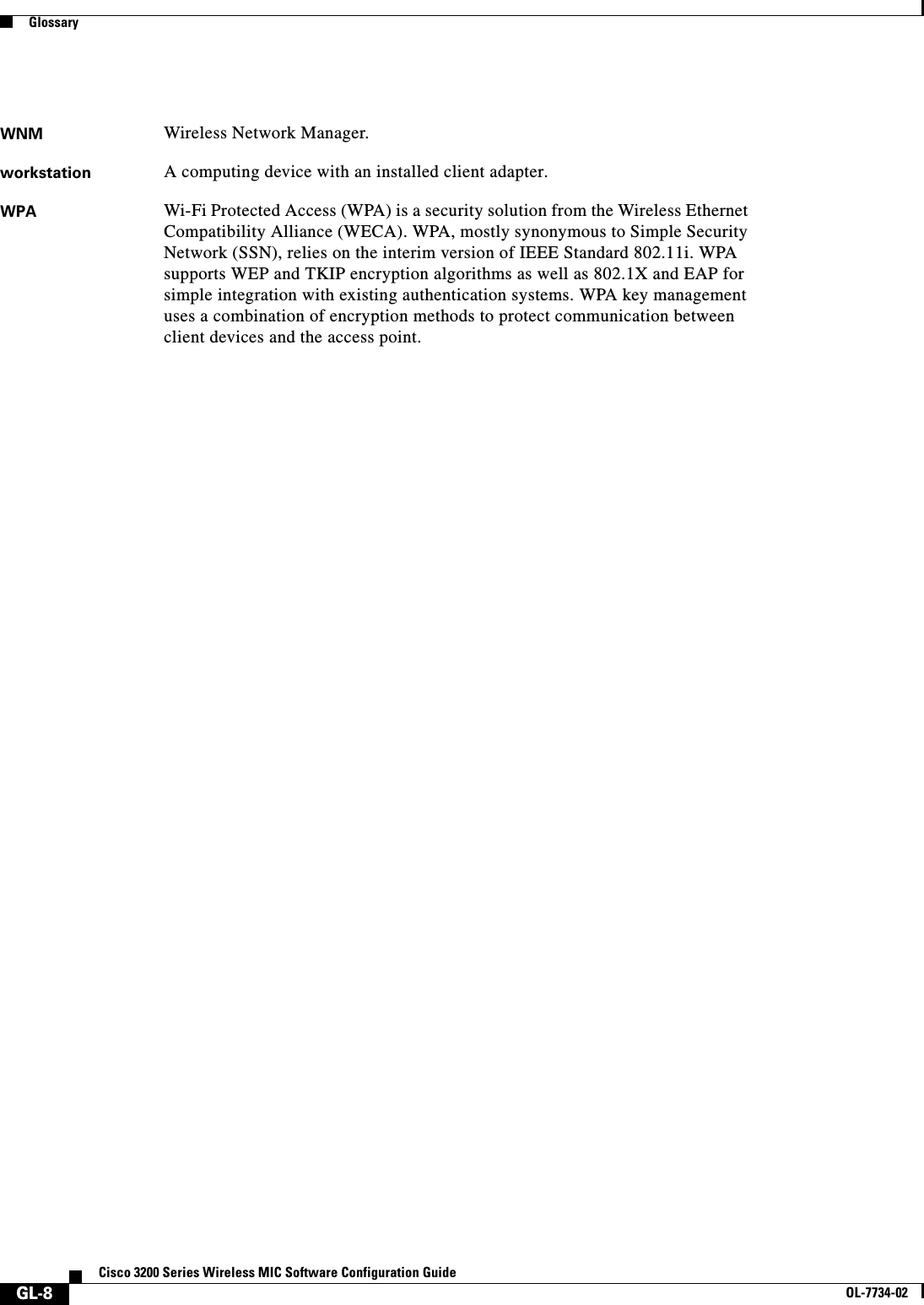
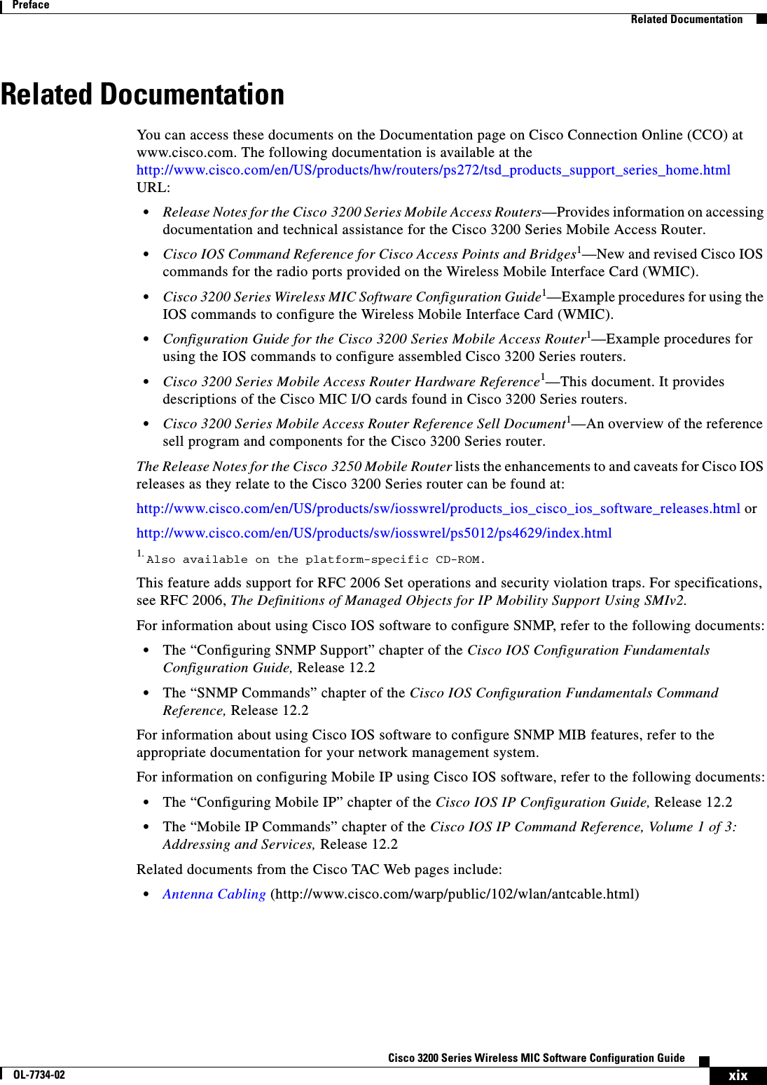
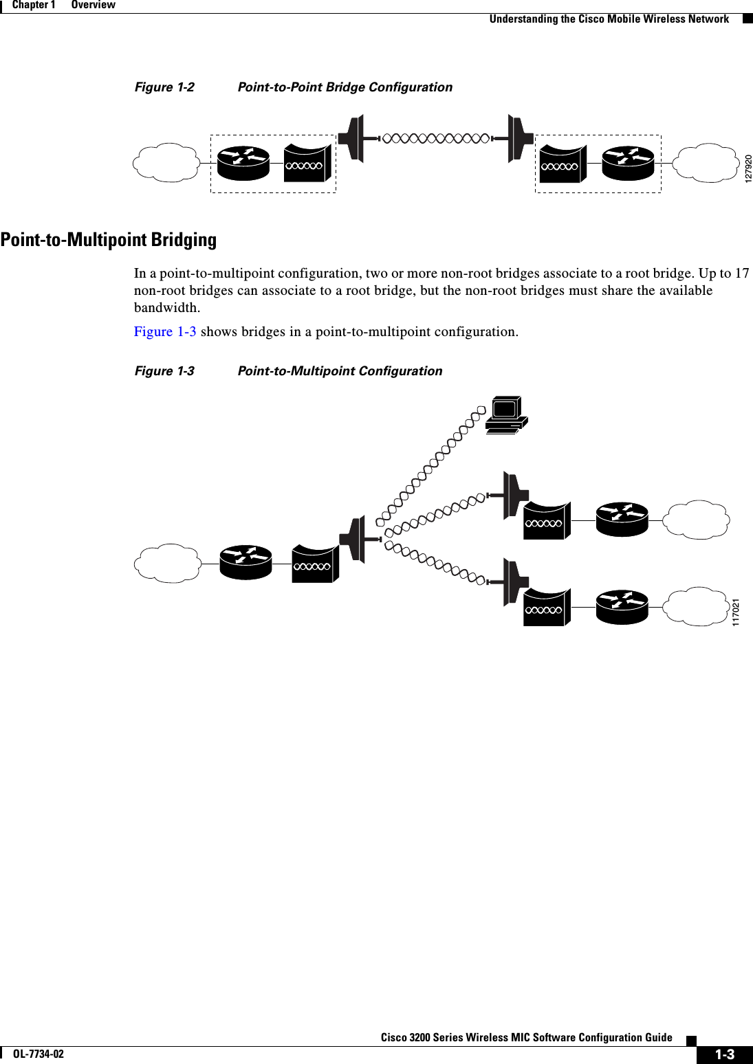
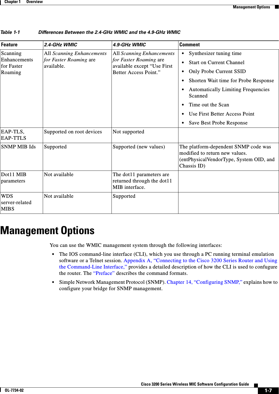
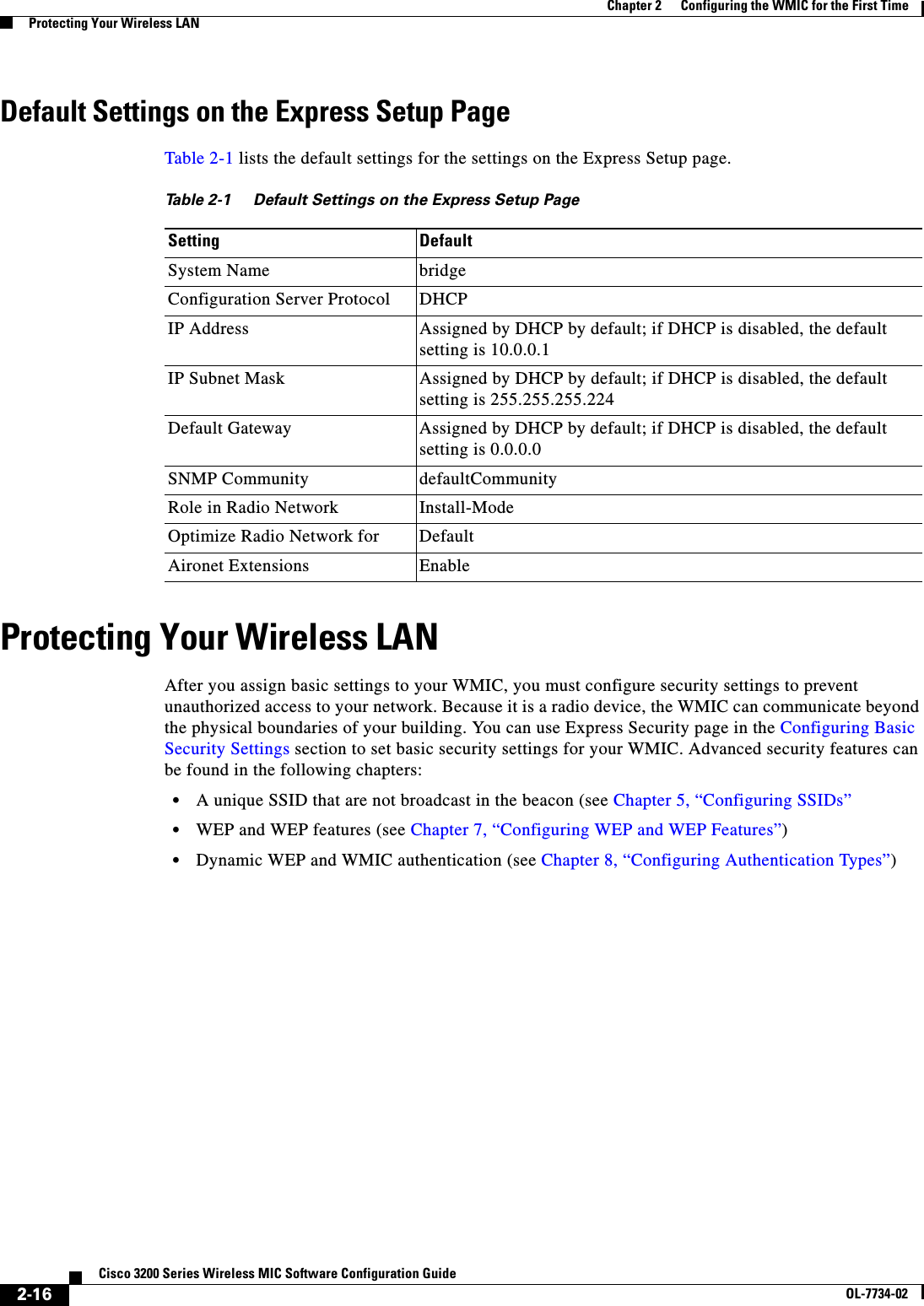
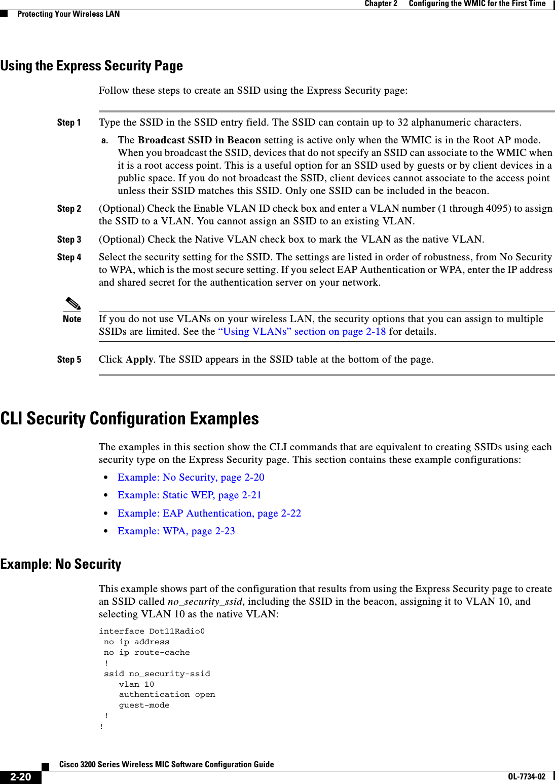
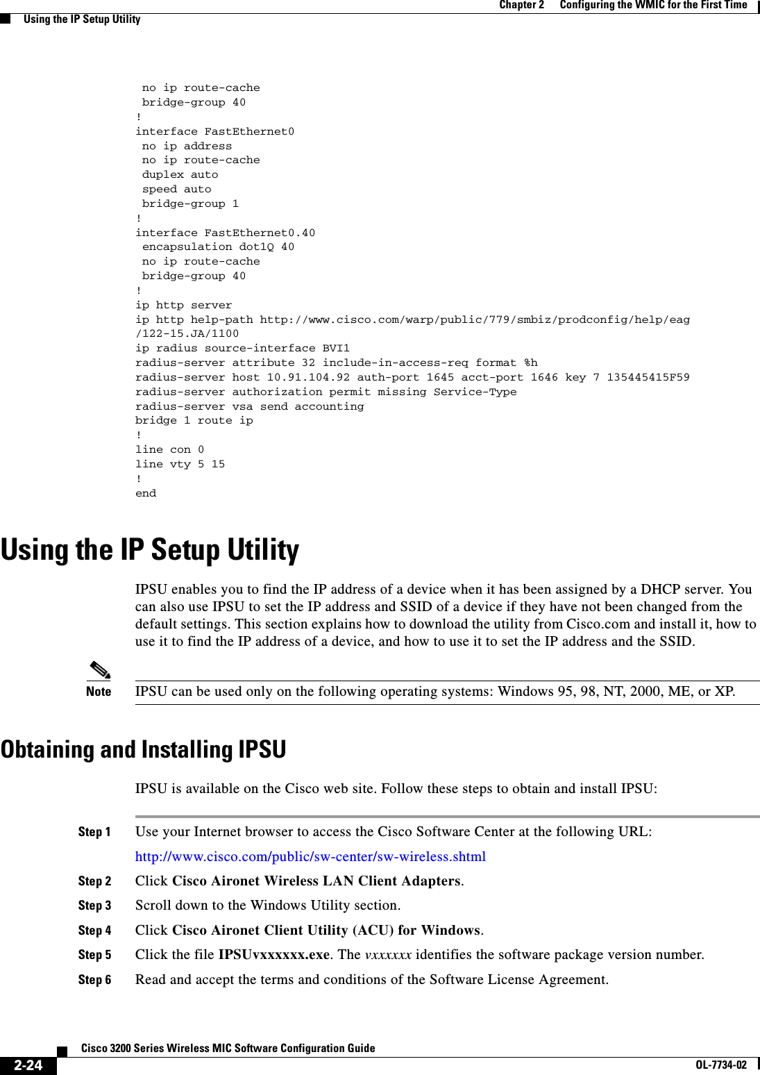
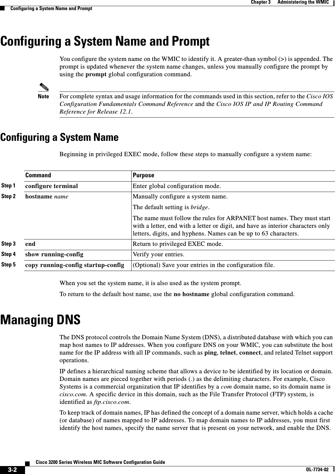
![xviiCisco 3200 Series Wireless MIC Software Configuration GuideOL-7734-02Preface ConventionsConventionsThis publication uses these conventions to convey instructions and information:Command descriptions use these conventions:•Commands and keywords are in boldface text.•Arguments for which you supply values are in italic.•Square brackets ([ ]) mean optional elements.•Braces ({ }) group required choices, and vertical bars ( | ) separate the alternative elements.•Braces and vertical bars within square brackets ([{ | }]) mean a required choice within an optional element.Interactive examples use these conventions:•Terminal sessions and system displays are in screen font.•Information you enter is in boldface screen font.•Non printing characters, such as passwords or tabs, are in angle brackets (< >).Notes, cautions, and timesavers use these conventions and symbols:Tip Means the following will help you solve a problem. The tips information might not be troubleshooting or even an action, but could be useful information.Note Means reader take note. Notes contain helpful suggestions or references to materials not contained in this manual.Caution Means reader be careful. In this situation, you might do something that could result equipment damage or loss of data.WarningThis warning symbol means danger. You are in a situation that could cause bodily injury. Before you work on any equipment, be aware of the hazards involved with electrical circuitry and be familiar with standard practices for preventing accidents. (To see translations of the warnings that appear in this publication, refer to the appendix “Translated Safety Warnings.”)WaarschuwingDit waarschuwingssymbool betekent gevaar. U verkeert in een situatie die lichamelijk letsel kan veroorzaken. Voordat u aan enige apparatuur gaat werken, dient u zich bewust te zijn van de bij elektrische schakelingen betrokken risico’s en dient u op de hoogte te zijn van standaard maatregelen om ongelukken te voorkomen. (Voor vertalingen van de waarschuwingen die in deze publicatie verschijnen, kunt u het aanhangsel “Translated Safety Warnings” (Vertalingen van veiligheidsvoorschriften) raadplegen.)](https://usermanual.wiki/Cisco-Systems/XSCLCR14/User-Guide-558354-Page-17.png)
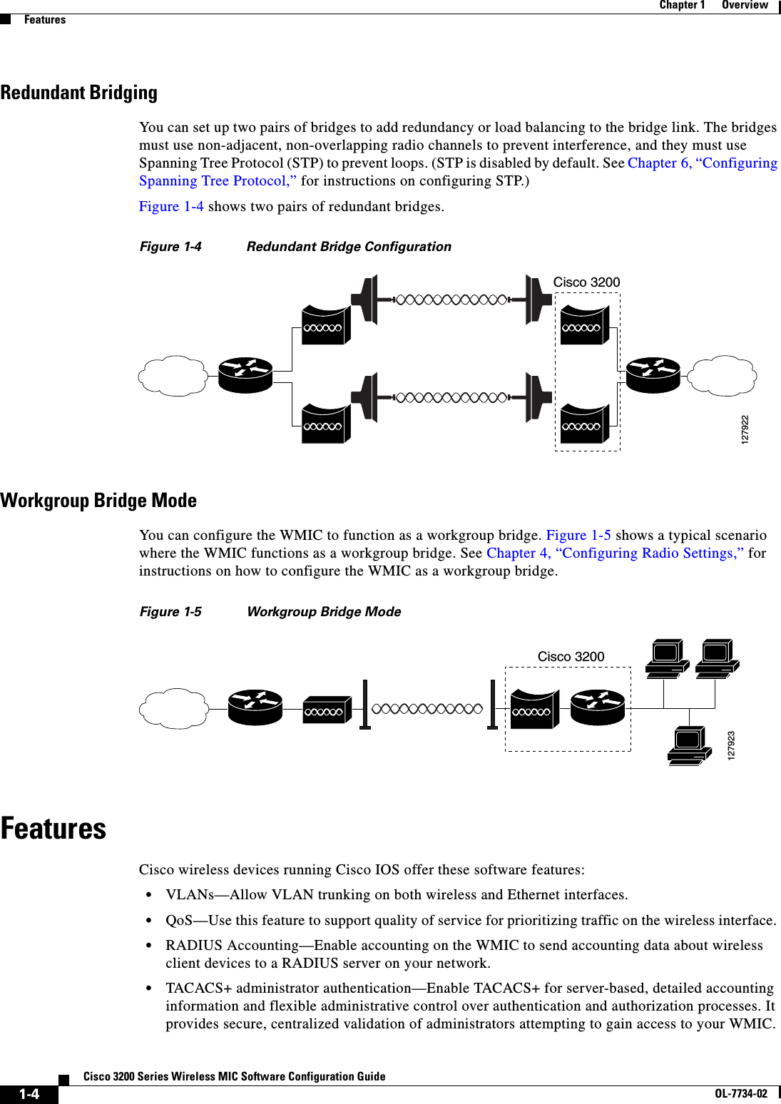
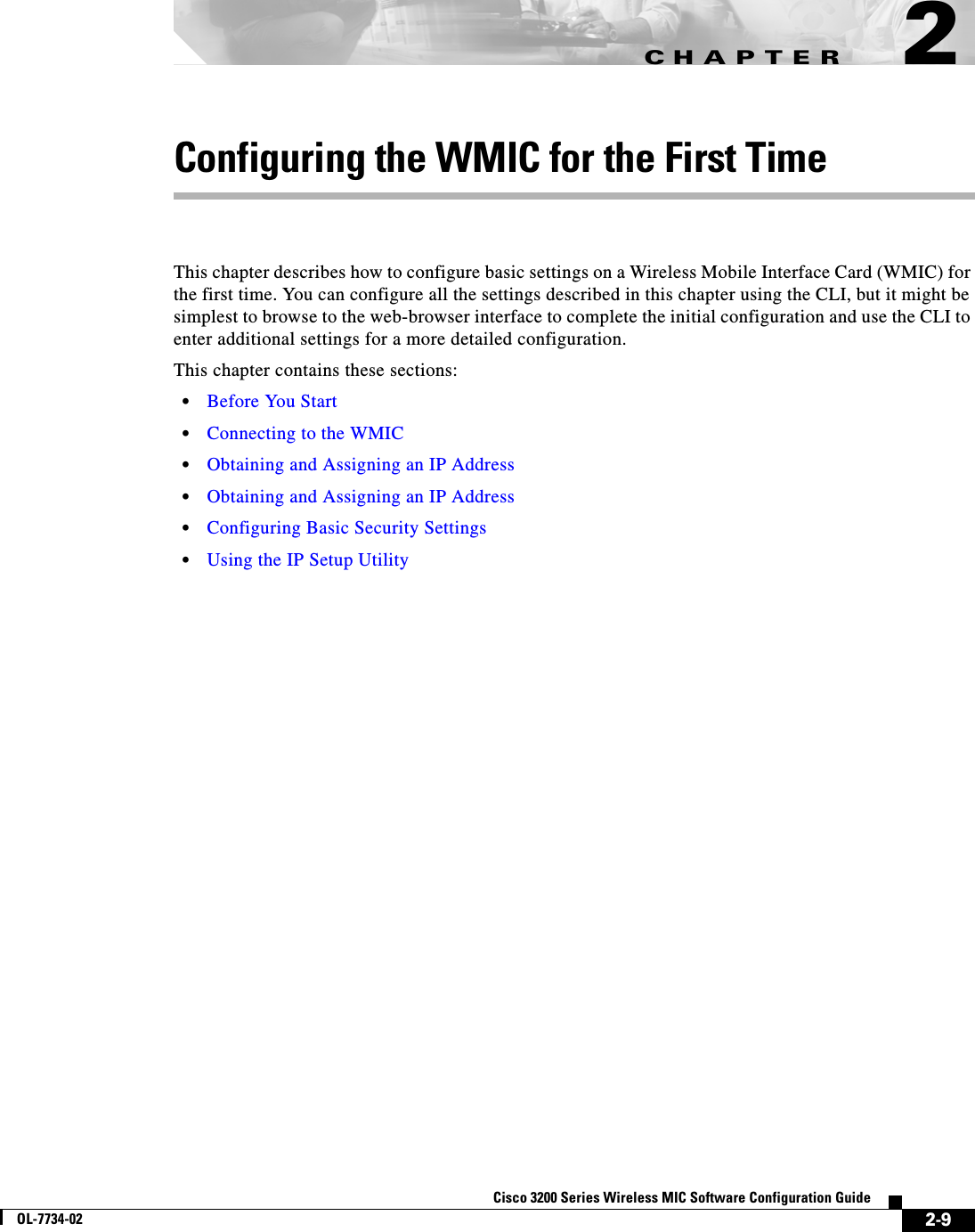
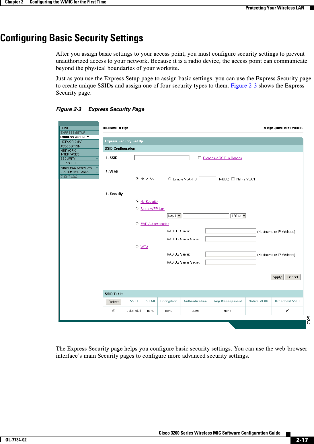
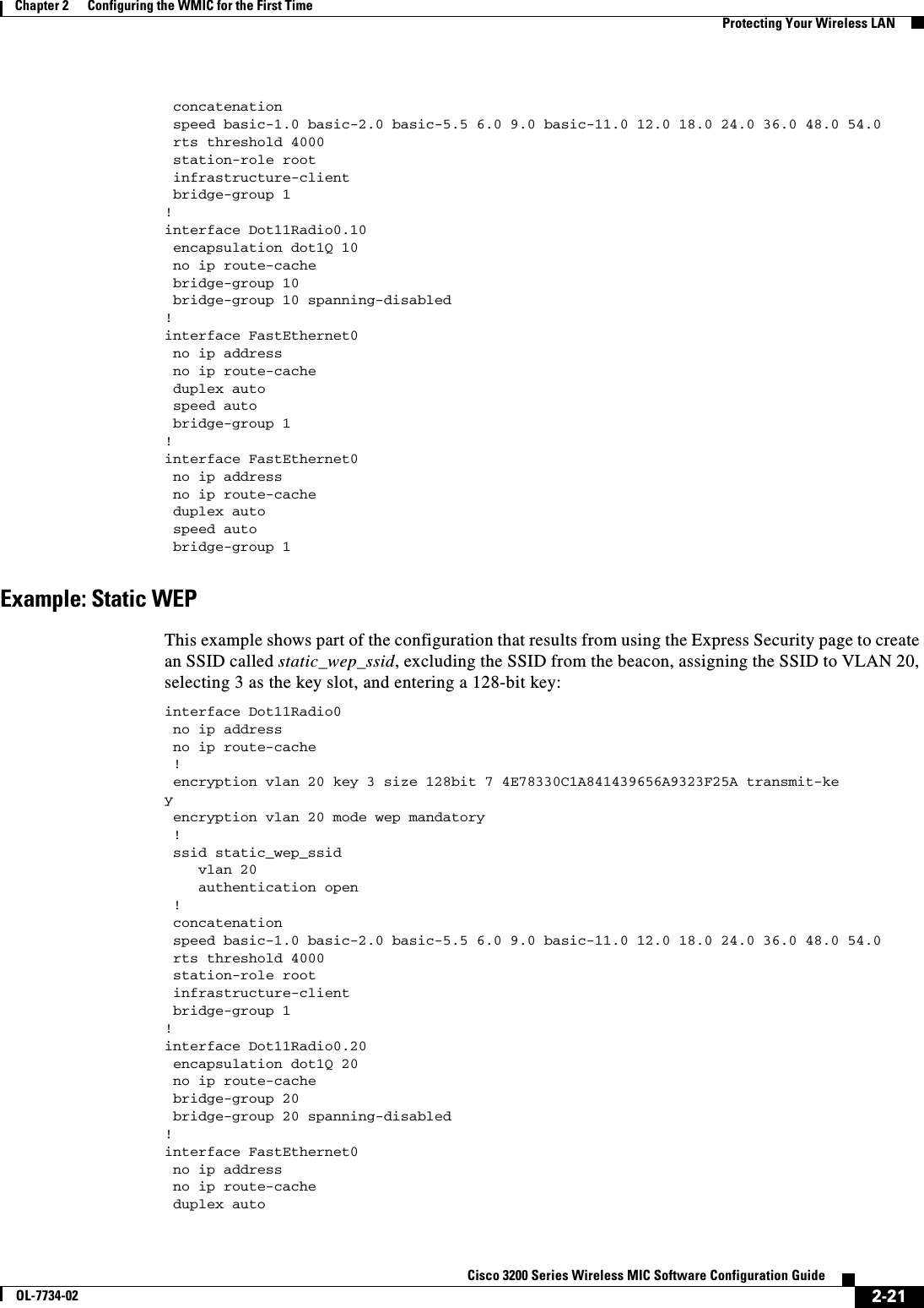
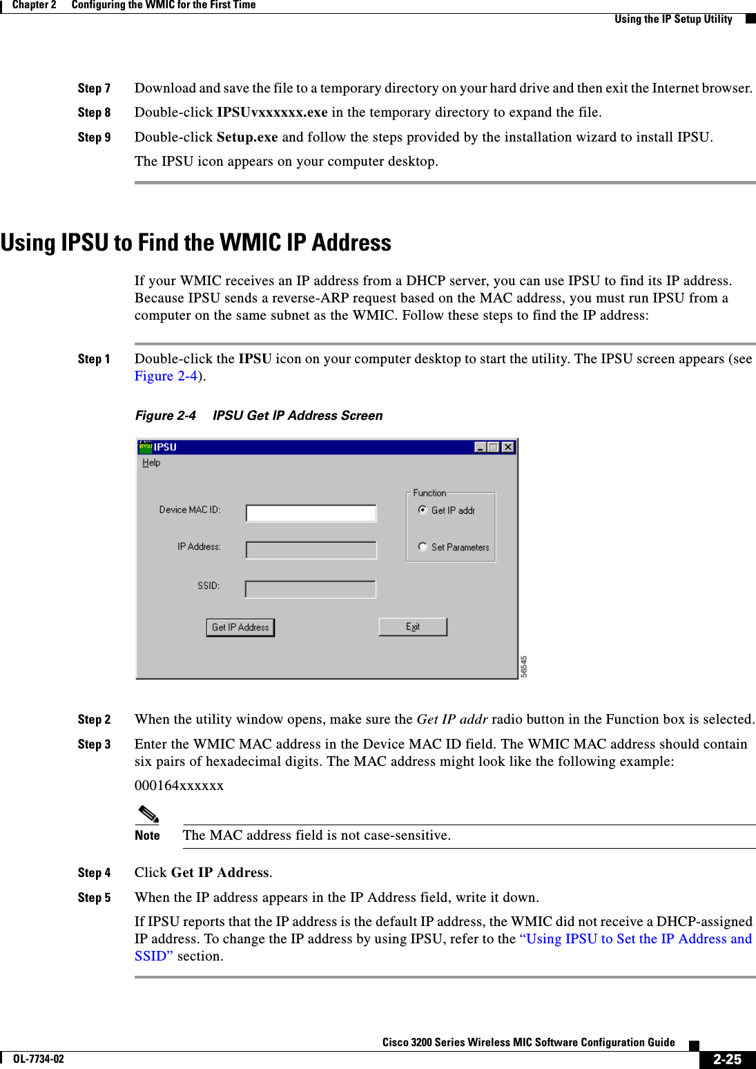
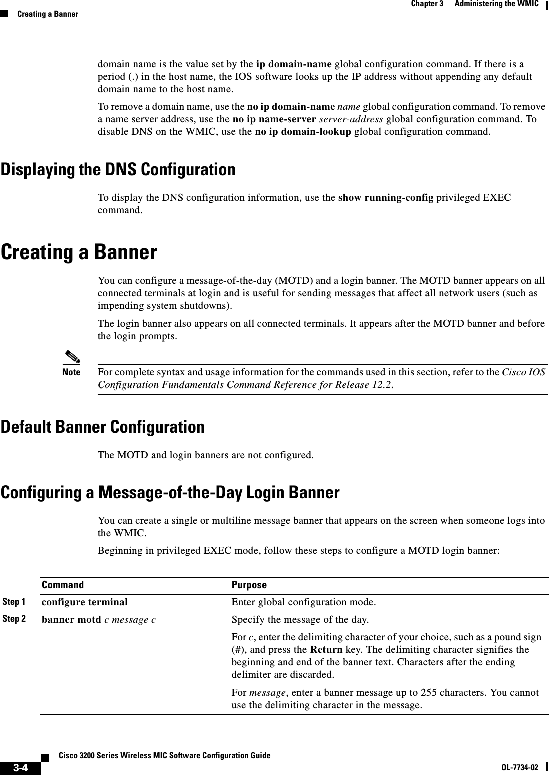
![xviiiCisco 3200 Series Wireless MIC Software Configuration GuideOL-7734-02Preface ConventionsVaroitusTämä varoitusmerkki merkitsee vaaraa. Olet tilanteessa, joka voi johtaa ruumiinvammaan. Ennen kuin työskentelet minkään laitteiston parissa, ota selvää sähkökytkentöihin liittyvistä vaaroista ja tavanomaisista onnettomuuksien ehkäisykeinoista. (Tässä julkaisussa esiintyvien varoitusten käännökset löydät liitteestä "Translated Safety Warnings" (käännetyt turvallisuutta koskevat varoitukset).)AttentionCe symbole d’avertissement indique un danger. Vous vous trouvez dans une situation pouvant entraîner des blessures. Avant d’accéder à cet équipement, soyez conscient des dangers posés par les circuits électriques et familiarisez-vous avec les procédures courantes de prévention des accidents. Pour obtenir les traductions des mises en garde figurant dans cette publication, veuillez consulter l’annexe intitulée « Translated Safety Warnings » (Traduction des avis de sécurité).WarnungDieses Warnsymbol bedeutet Gefahr. Sie befinden sich in einer Situation, die zu einer Körperverletzung führen könnte. Bevor Sie mit der Arbeit an irgendeinem Gerät beginnen, seien Sie sich der mit elektrischen Stromkreisen verbundenen Gefahren und der Standardpraktiken zur Vermeidung von Unfällen bewußt. (Übersetzungen der in dieser Veröffentlichung enthaltenen Warnhinweise finden Sie im Anhang mit dem Titel “Translated Safety Warnings” (Übersetzung der Warnhinweise).)AvvertenzaQuesto simbolo di avvertenza indica un pericolo. Si è in una situazione che può causare infortuni. Prima di lavorare su qualsiasi apparecchiatura, occorre conoscere i pericoli relativi ai circuiti elettrici ed essere al corrente delle pratiche standard per la prevenzione di incidenti. La traduzione delle avvertenze riportate in questa pubblicazione si trova nell’appendice, “Translated Safety Warnings” (Traduzione delle avvertenze di sicurezza).AdvarselDette varselsymbolet betyr fare. Du befinner deg i en situasjon som kan føre til personskade. Før du utfører arbeid på utstyr, må du være oppmerksom på de faremomentene som elektriske kretser innebærer, samt gjøre deg kjent med vanlig praksis når det gjelder å unngå ulykker. (Hvis du vil se oversettelser av de advarslene som finnes i denne publikasjonen, kan du se i vedlegget "Translated Safety Warnings" [Oversatte sikkerhetsadvarsler].)AvisoEste símbolo de aviso indica perigo. Encontra-se numa situação que lhe poderá causar danos fisicos. Antes de começar a trabalhar com qualquer equipamento, familiarize-se com os perigos relacionados com circuitos eléctricos, e com quaisquer práticas comuns que possam prevenir possíveis acidentes. (Para ver as traduções dos avisos que constam desta publicação, consulte o apêndice “Translated Safety Warnings” - “Traduções dos Avisos de Segurança”).¡Advertencia!Este símbolo de aviso significa peligro. Existe riesgo para su integridad física. Antes de manipular cualquier equipo, considerar los riesgos que entraña la corriente eléctrica y familiarizarse con los procedimientos estándar de prevención de accidentes. (Para ver traducciones de las advertencias que aparecen en esta publicación, consultar el apéndice titulado “Translated Safety Warnings.”)Varning!Denna varningssymbol signalerar fara. Du befinner dig i en situation som kan leda till personskada. Innan du utför arbete på någon utrustning måste du vara medveten om farorna med elkretsar och känna till vanligt förfarande för att förebygga skador. (Se förklaringar av de varningar som förekommer i denna publikation i appendix "Translated Safety Warnings" [Översatta säkerhetsvarningar].)](https://usermanual.wiki/Cisco-Systems/XSCLCR14/User-Guide-558354-Page-18.png)
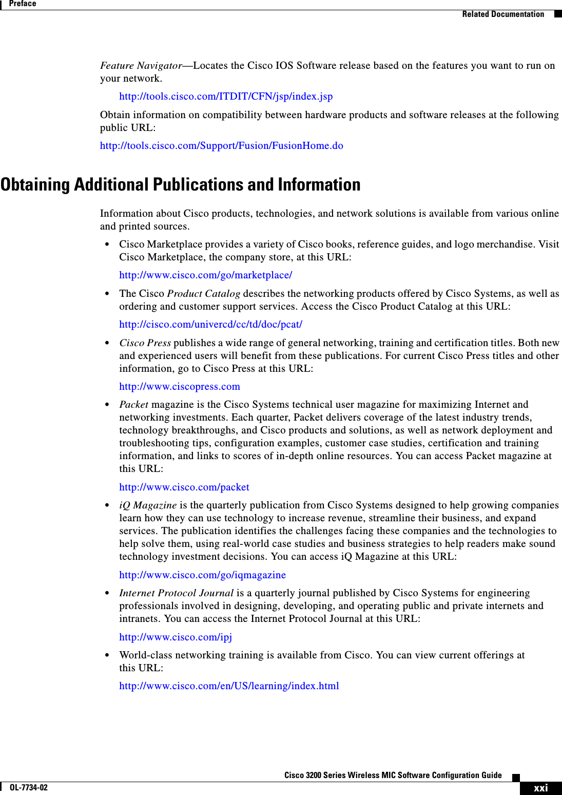
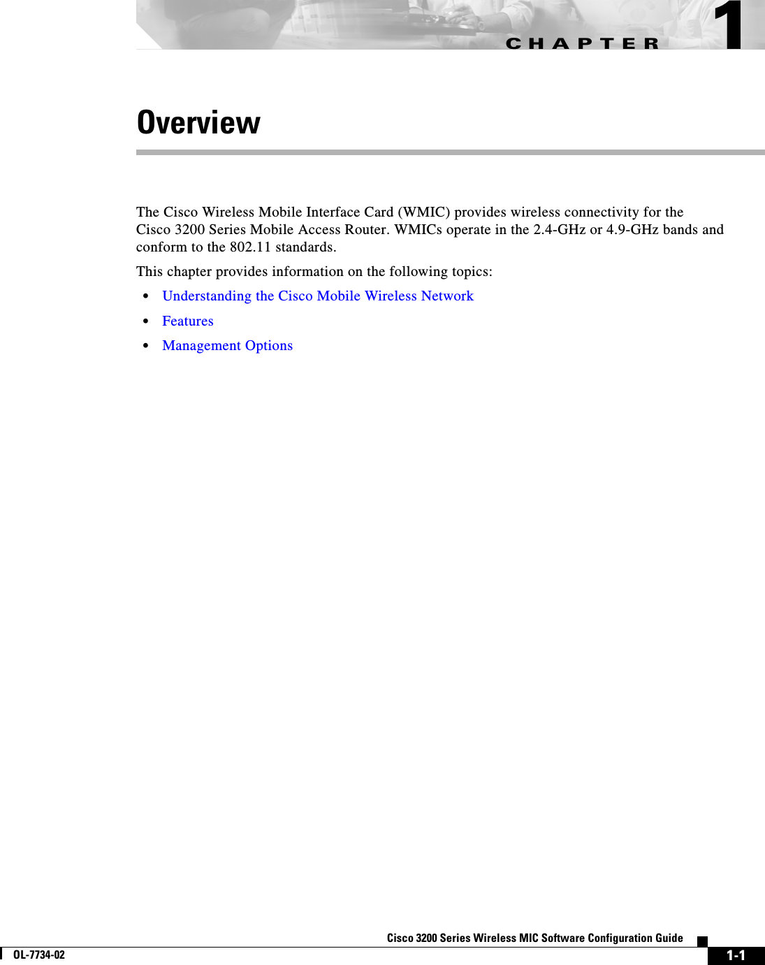
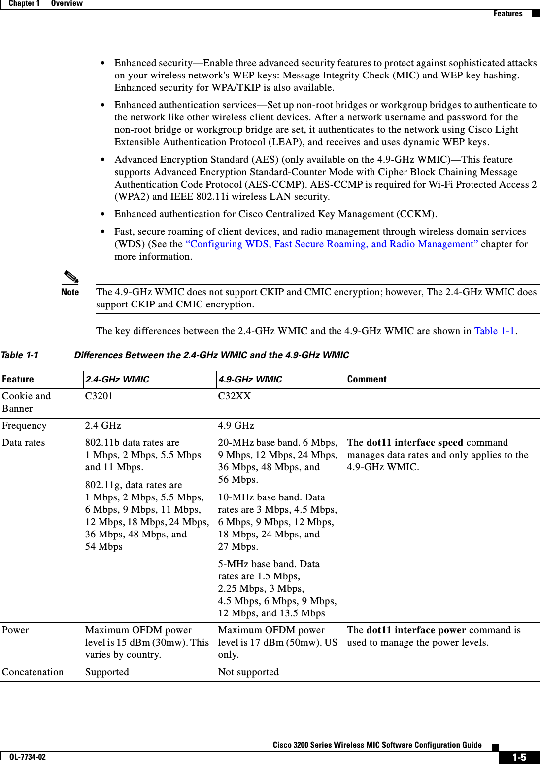

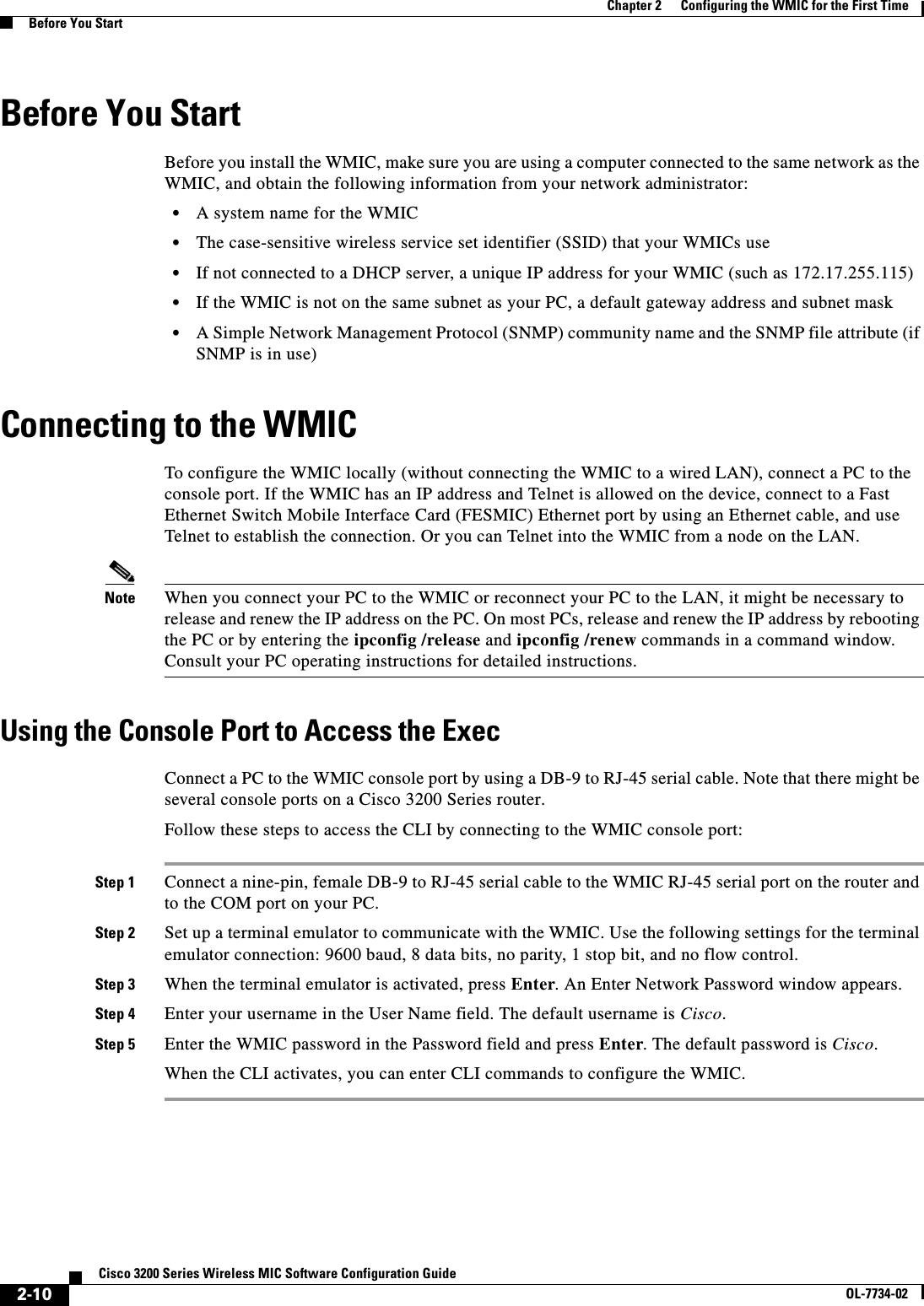
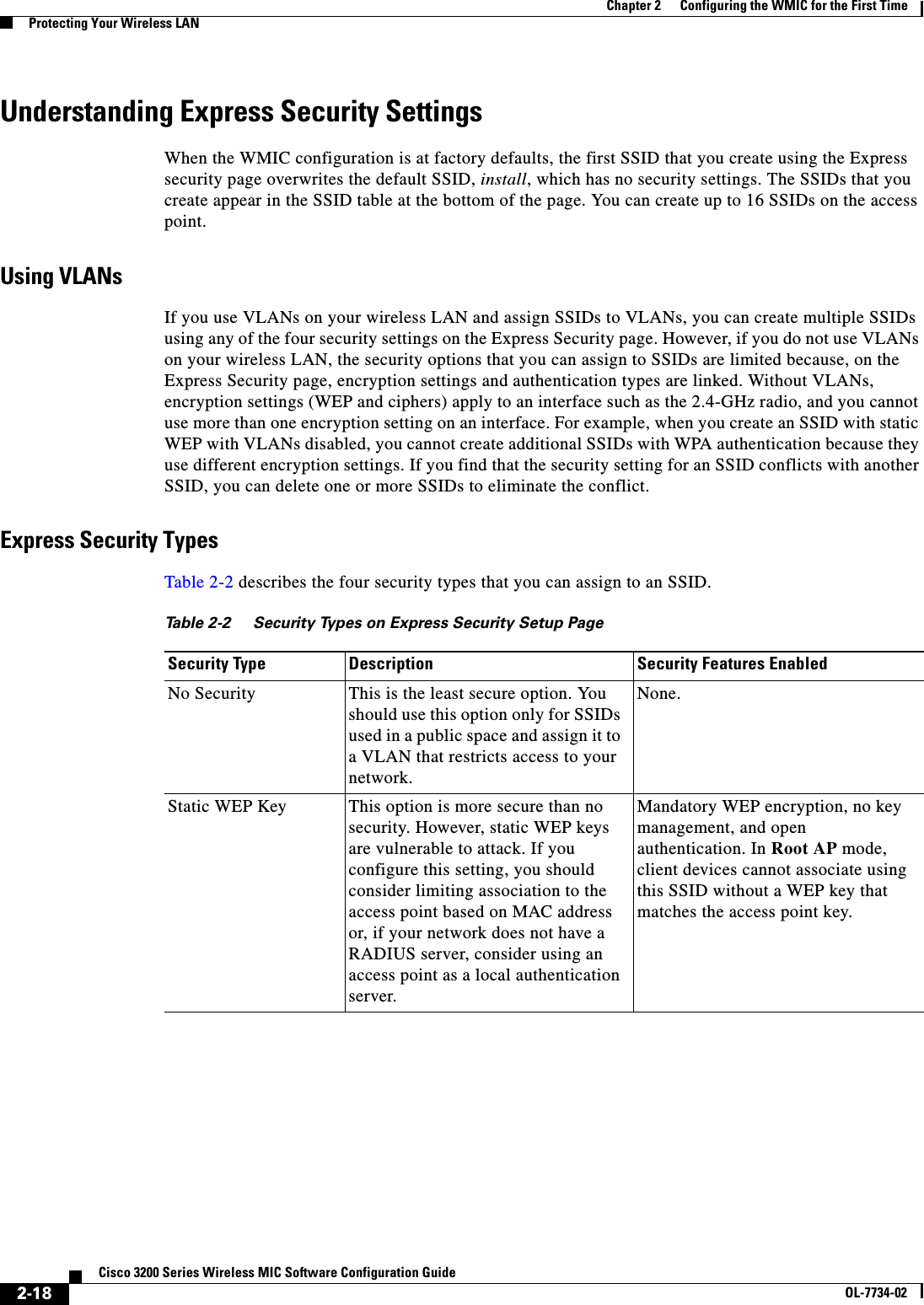
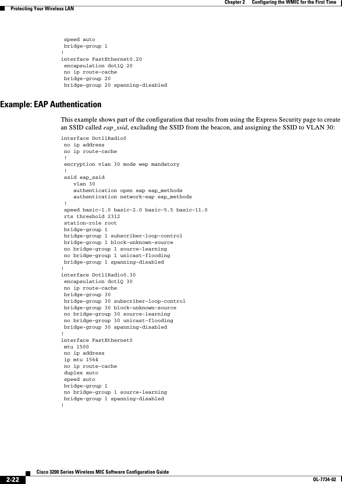
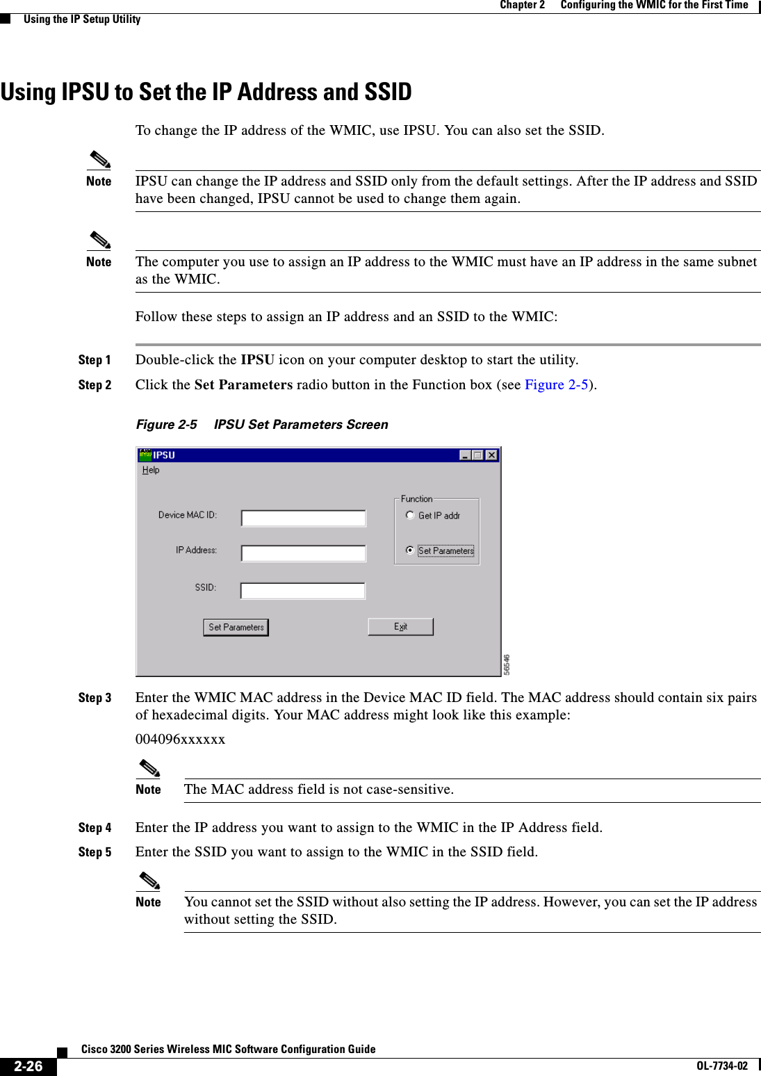


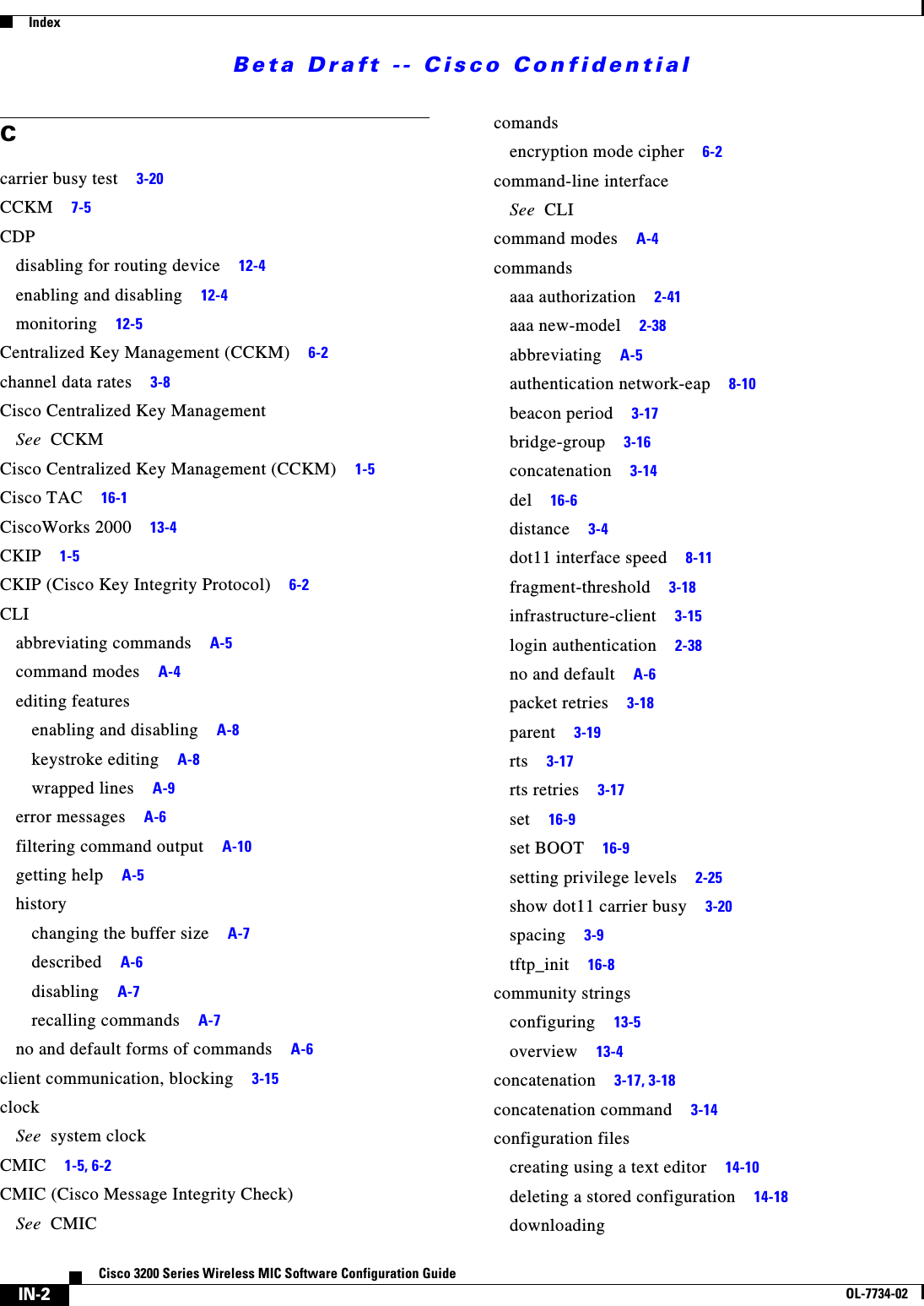
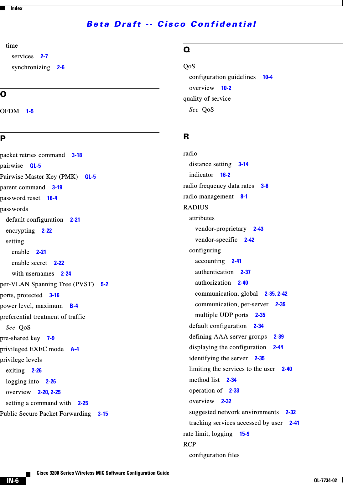
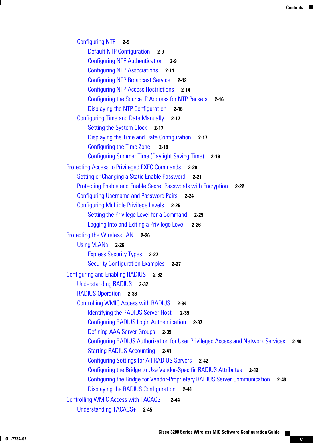
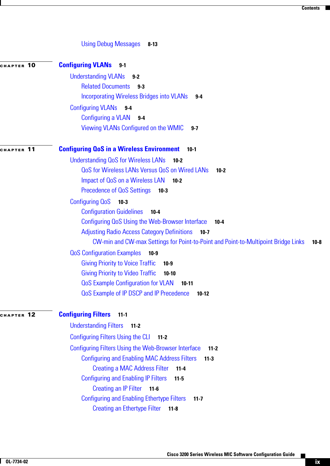
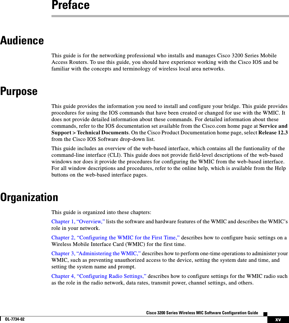
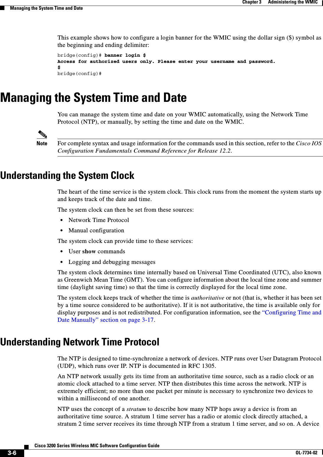
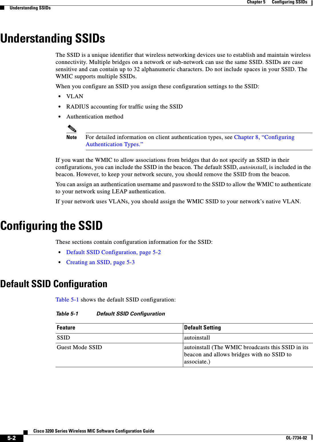
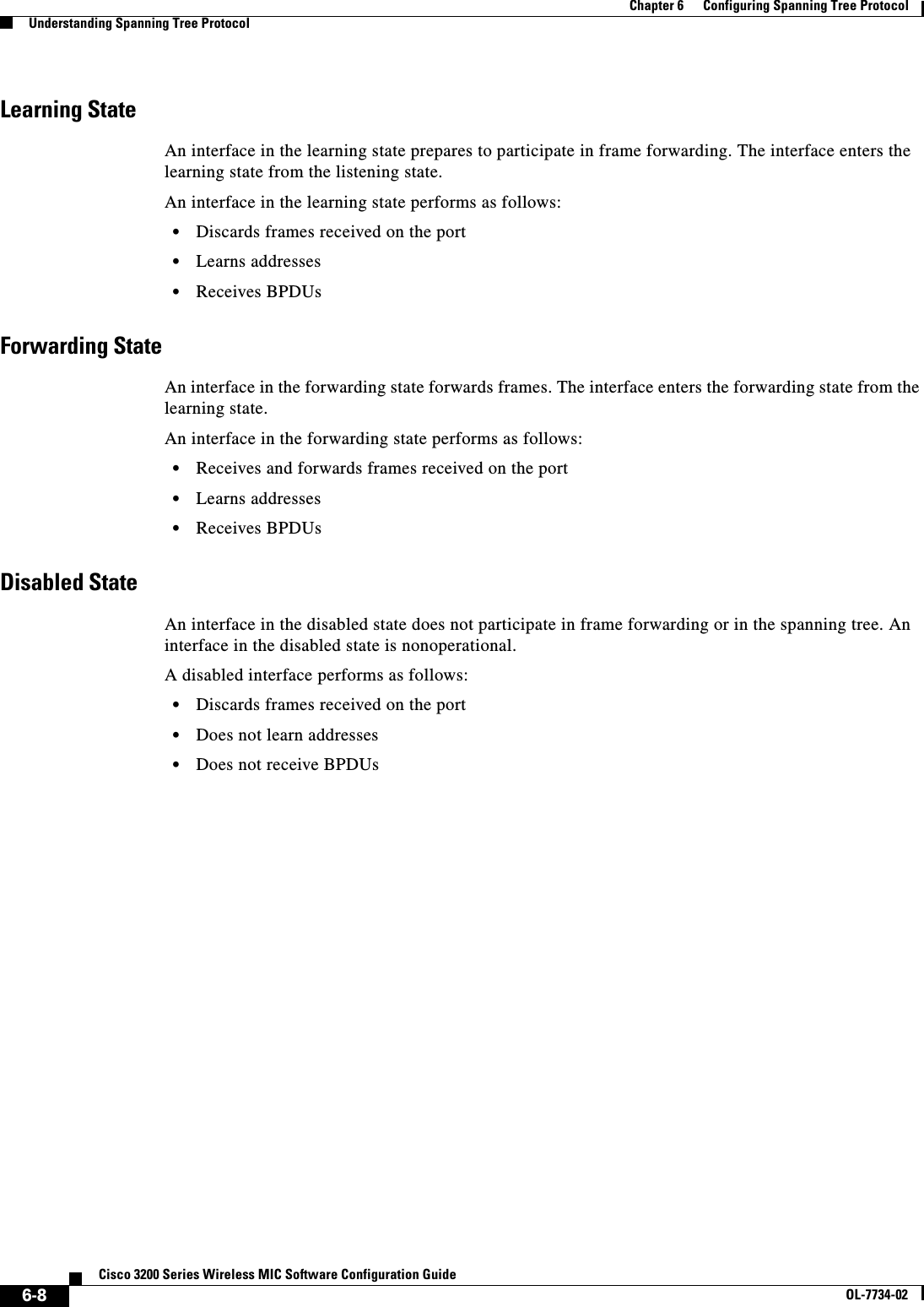
![3-3Cisco 3200 Series Wireless MIC Software Configuration GuideOL-7734-02Chapter 3 Administering the WMICManaging DNSDefault DNS ConfigurationTable 3-1 shows the default DNS configuration.Setting Up DNSBeginning in privileged EXEC mode, follow these steps to set up your WMIC to use the DNS:If you use the WMIC IP address as its host name, the IP address is used and no DNS query occurs. If you configure a host name that contains no periods (.), a period followed by the default domain name is appended to the host name before the DNS query is made to map the name to an IP address. The default Table 3-1 Default DNS ConfigurationFeature Default SettingDNS enable state Disabled.DNS default domain name None configured.DNS servers No name server addresses are configured.Command PurposeStep 1 configure terminal Enter global configuration mode.Step 2 ip domain-name name Define a default domain name that the software uses to complete unqualified host names (names without a dotted-decimal domain name).Do not include the initial period that separates an unqualified name from the domain name.At boot time, no domain name is configured; however, if the configuration comes from a BOOTP or Dynamic Host Configuration Protocol (DHCP) server, then the default domain name might be set by the BOOTP or DHCP server (if the servers were configured with this information).Step 3 ip name-server server-address1[server-address2 ... server-address6]Specify the address of one or more name servers to use for name and address resolution.You can specify up to six name servers. Separate each server address with a space. The first server specified is the primary server. The WMIC sends DNS queries to the primary server first. If that query fails, the backup servers are queried.Step 4 ip domain-lookup (Optional) Enable DNS-based host name-to-address translation on your WMIC. This feature is enabled by default. If your network devices require connectivity with devices in networks for which you do not control name assignment, you can dynamically assign device names that uniquely identify your devices by using the global Internet naming scheme (DNS).Step 5 end Return to privileged EXEC mode.Step 6 show running-config Verify your entries.Step 7 copy running-config startup-config(Optional) Save your entries in the configuration file.](https://usermanual.wiki/Cisco-Systems/XSCLCR14/User-Guide-558354-Page-55.png)
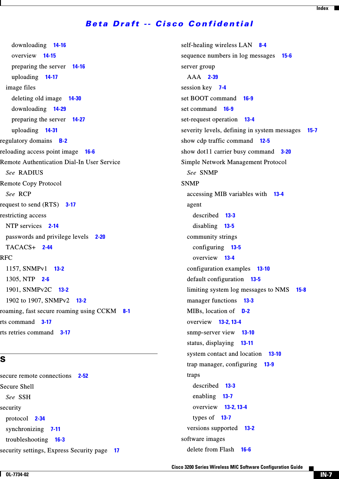
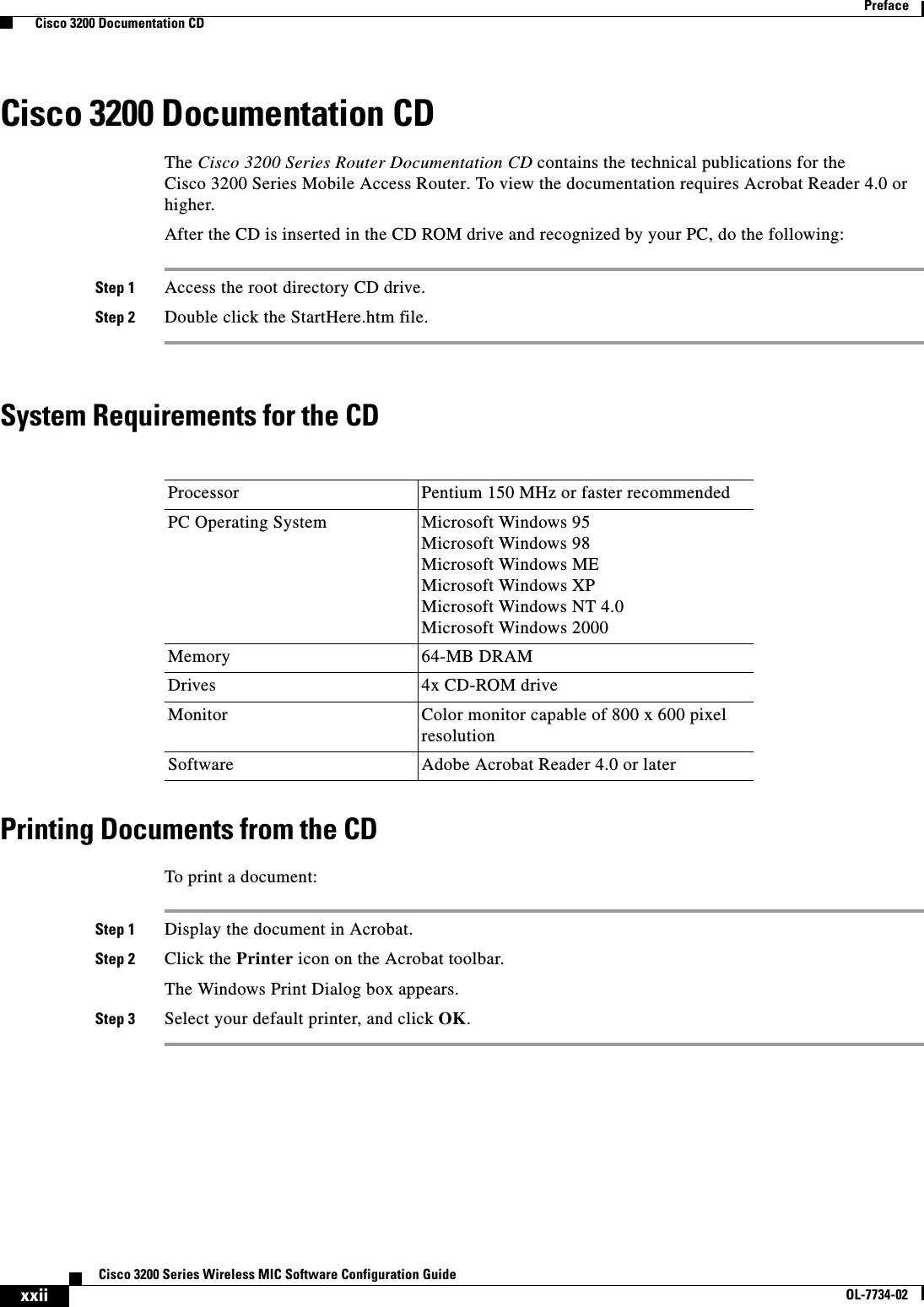
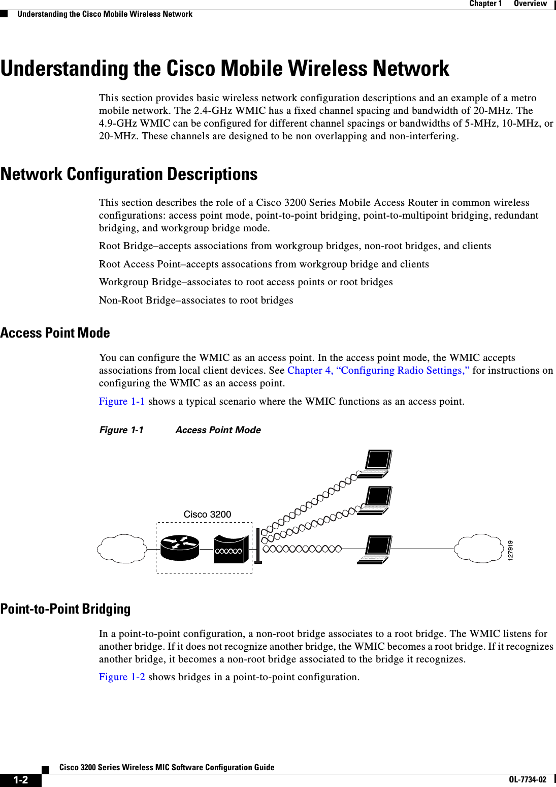
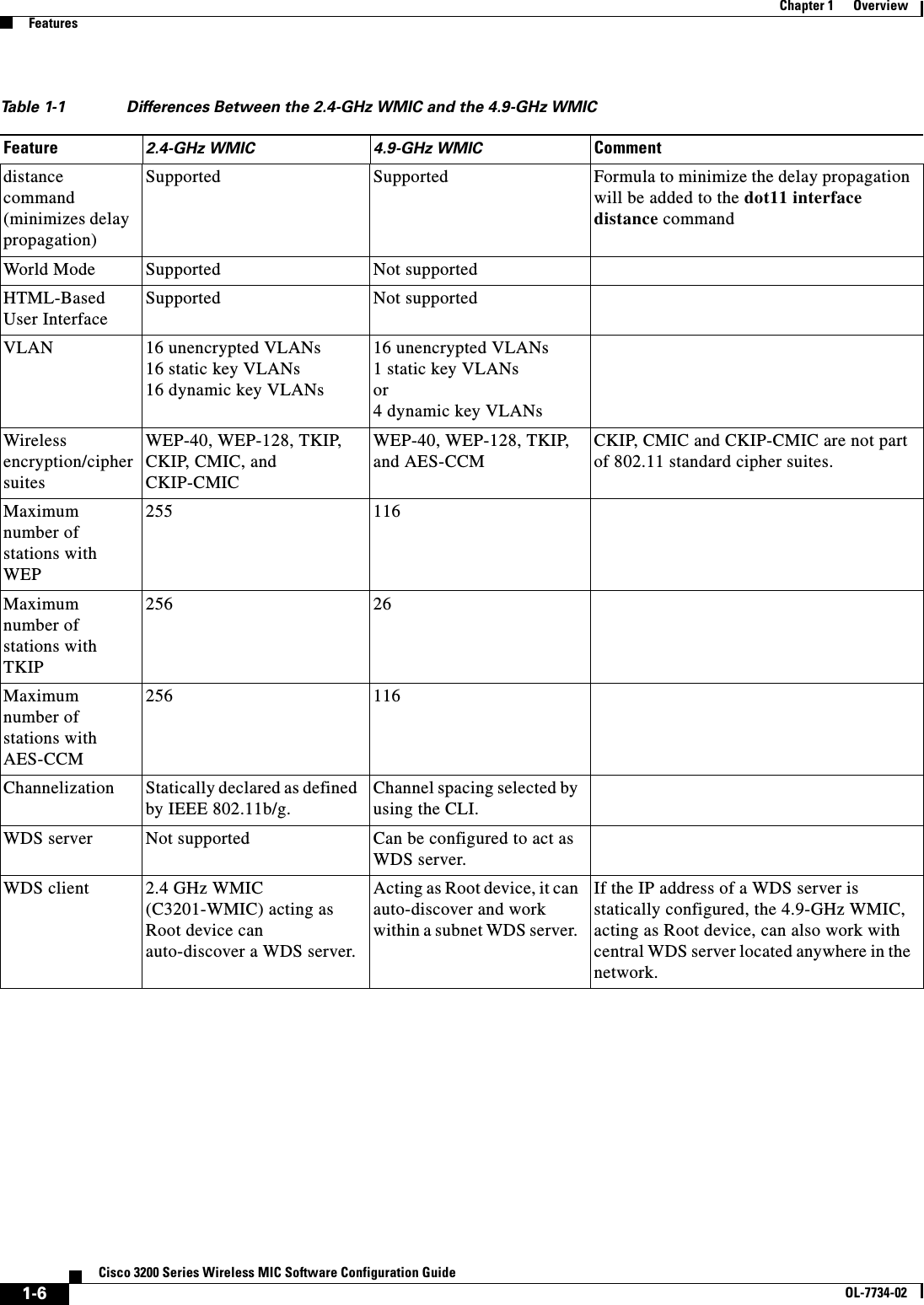
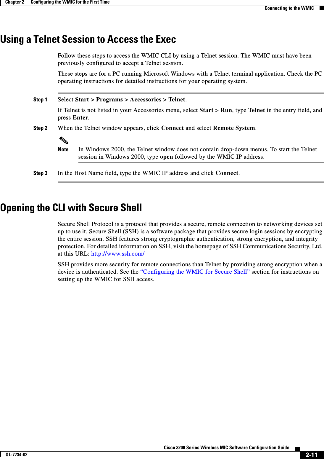
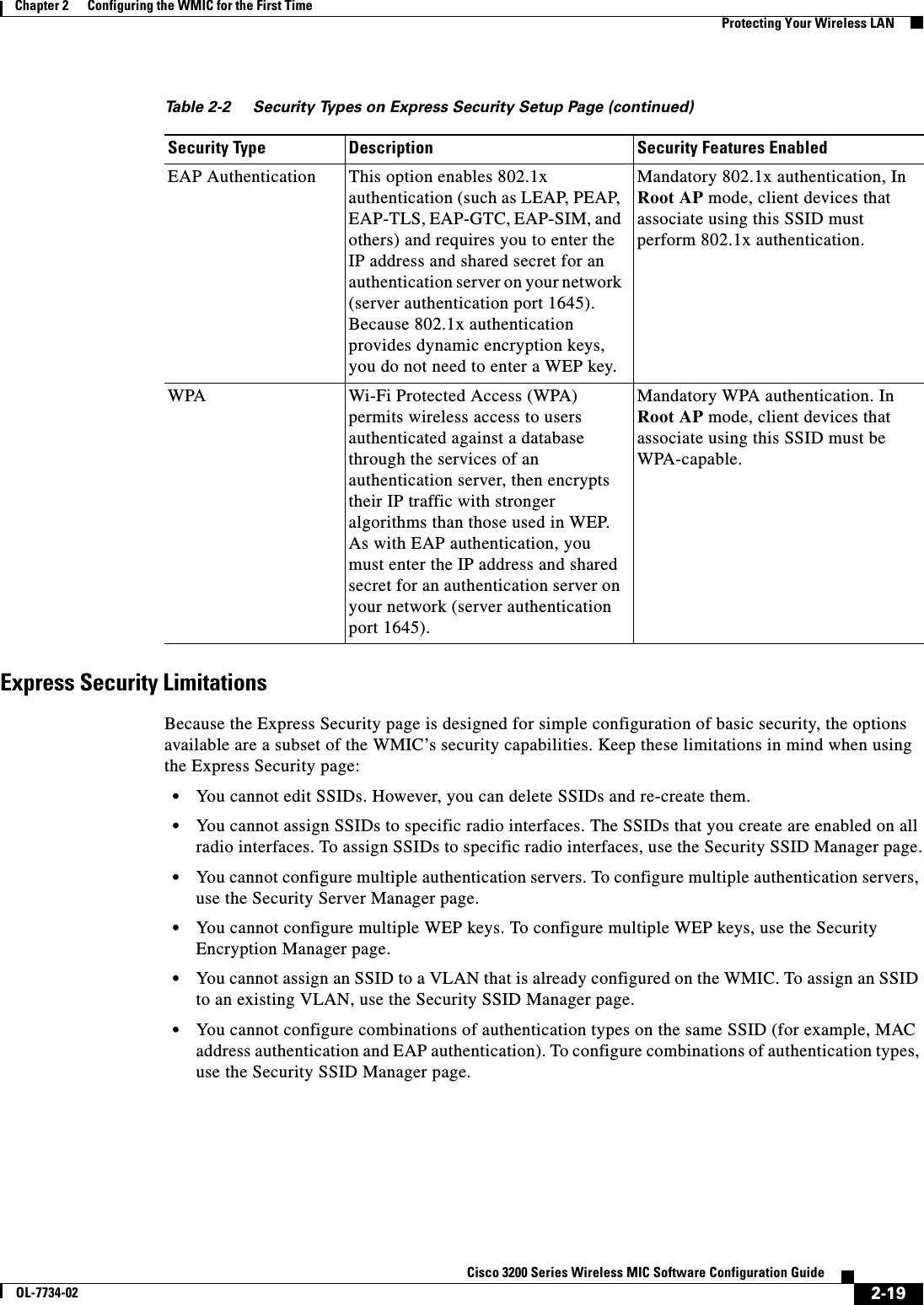
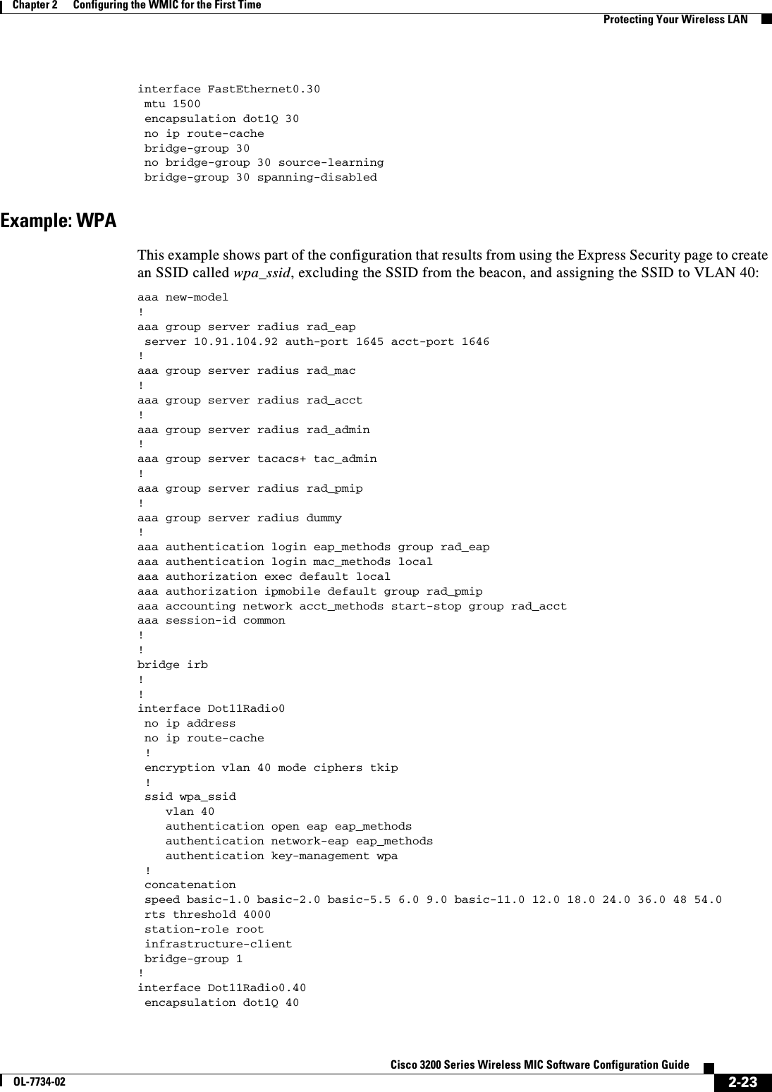
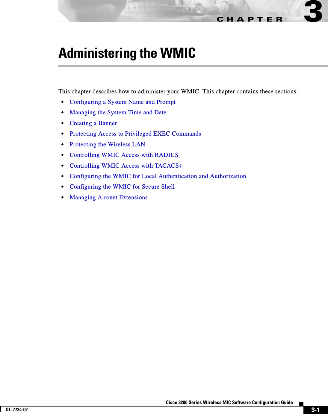
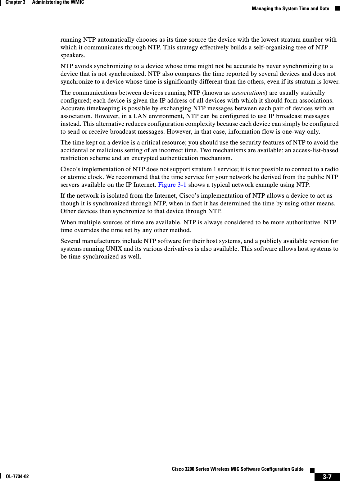
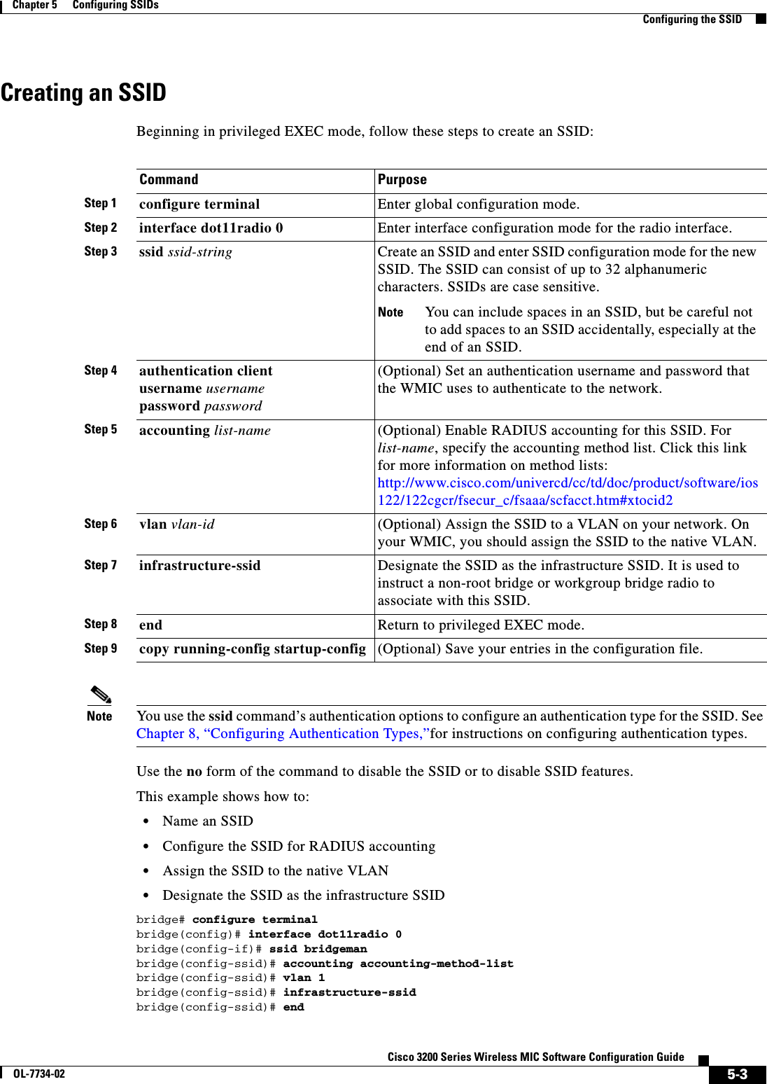
![3-5Cisco 3200 Series Wireless MIC Software Configuration GuideOL-7734-02Chapter 3 Administering the WMICCreating a BannerTo delete the MOTD banner, use the no banner motd global configuration command.This example shows how to configure a MOTD banner for the WMIC using the pound sign (#) symbol as the beginning and ending delimiter:bridge(config)# banner motd #This is a secure site. Only authorized users are allowed.For access, contact technical support.#bridge(config)#This example shows the banner displayed from the previous configuration:Unix> telnet 172.2.5.4Trying 172.2.5.4...Connected to 172.2.5.4.Escape character is '^]'.This is a secure site. Only authorized users are allowed.For access, contact technical support.User Access VerificationPassword:Configuring a Login BannerYou can configure a login banner to appear on all connected terminals. This banner appears after the MOTD banner and before the login prompt.Beginning in privileged EXEC mode, follow these steps to configure a login banner:To delete the login banner, use the no banner login global configuration command.Step 3 end Return to privileged EXEC mode.Step 4 show running-config Verify your entries.Step 5 copy running-config startup-config (Optional) Save your entries in the configuration file.Command PurposeCommand PurposeStep 1 configure terminal Enter global configuration mode.Step 2 banner login c message c Specify the login message.For c, enter the delimiting character of your choice, such as a pound sign (#), and press the Return key. The delimiting character signifies the beginning and end of the banner text. Characters after the ending delimiter are discarded.For message, enter a login message up to 255 characters. You cannot use the delimiting character in the message.Step 3 end Return to privileged EXEC mode.Step 4 show running-config Verify your entries.Step 5 copy running-config startup-config (Optional) Save your entries in the configuration file.](https://usermanual.wiki/Cisco-Systems/XSCLCR14/User-Guide-558354-Page-57.png)
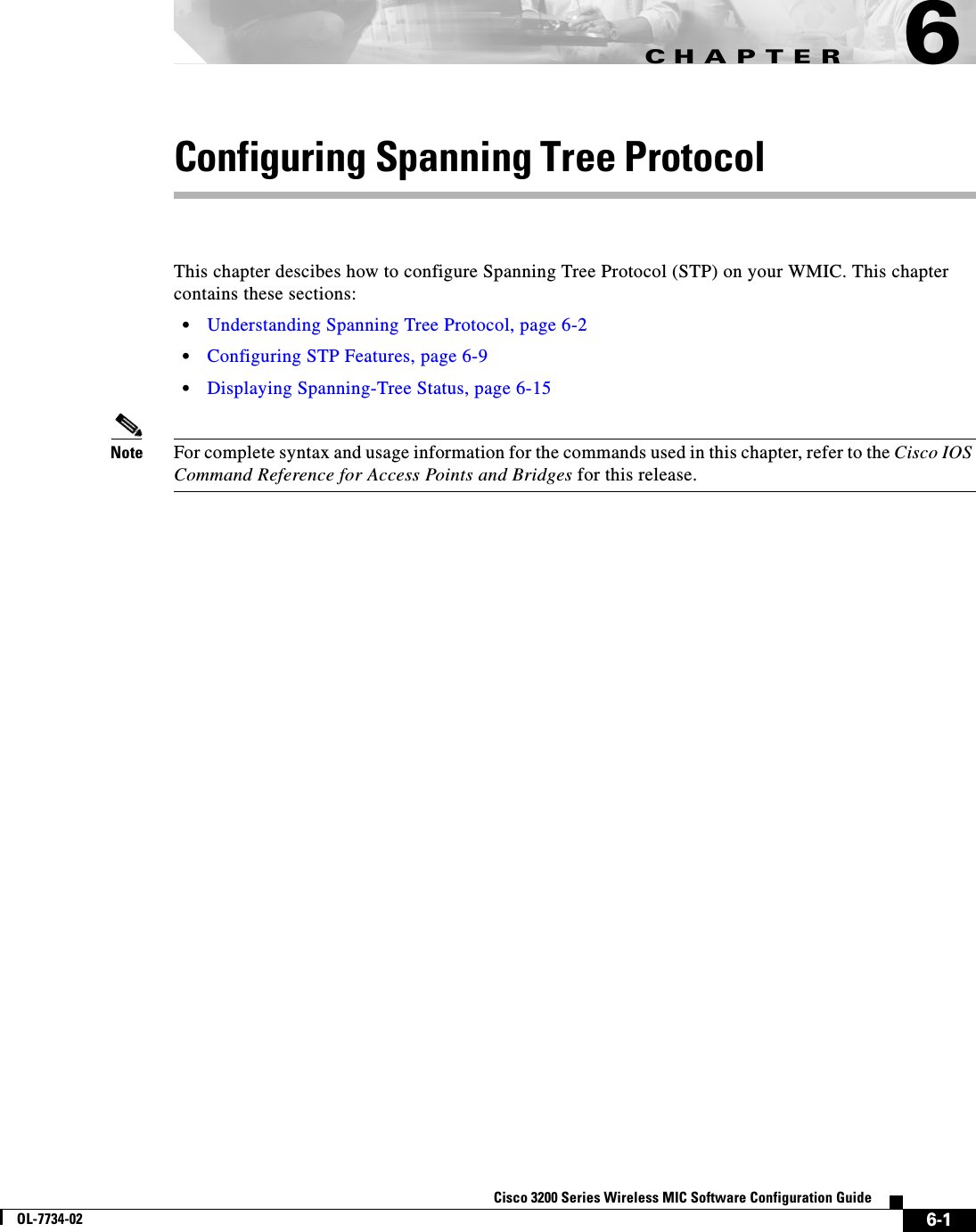
![3-11Cisco 3200 Series Wireless MIC Software Configuration GuideOL-7734-02Chapter 3 Administering the WMICManaging the System Time and DateConfiguring NTP AssociationsAn NTP association can be a peer association (this WMIC can either synchronize to the other device or allow the other device to synchronize to it), or it can be a server association (meaning that only this WMIC synchronizes to the other device, and not the other way around). Beginning in privileged EXEC mode, follow these steps to form an NTP association with another device:You need to configure only one end of an association; the other device can automatically establish the association. If you are using the default NTP version (version 3) and NTP synchronization does not occur, try using NTP version 2. Many NTP servers on the Internet run version 2.To remove a peer or server association, use the no ntp peer ip-address or the no ntp server ip-addressglobal configuration command.This example shows how to configure the WMIC to synchronize its system clock with the clock of the peer at IP address 172.16.22.44 using NTP version 2:bridge(config)# ntp server 172.16.22.44 version 2Command PurposeStep 1 configure terminal Enter global configuration mode.Step 2 ntp peer ip-address [version number][key keyid] [source interface] [prefer]orntp server ip-address [version number][key keyid] [source interface] [prefer]Configure the WMIC system clock to synchronize a peer or to be synchronized by a peer (peer association).orConfigure the WMIC system clock to be synchronized by a time server (server association).No peer or server associations are defined by default.•For ip-address in a peer association, specify either the IP address of the peer providing, or being provided, the clock synchronization. For a server association, specify the IP address of the time server providing the clock synchronization.•(Optional) For number, specify the NTP version number. The range is 1 to 3. By default, version 3 is selected.•(Optional) For keyid, enter the authentication key defined with the ntp authentication-key global configuration command.•(Optional) For interface, specify the interface from which to pick the IP source address. By default, the source IP address is taken from the outgoing interface.•(Optional) Enter the prefer keyword to make this peer or server the preferred one that provides synchronization. This keyword reduces switching back and forth between peers and servers.Step 3 end Return to privileged EXEC mode.Step 4 show running-config Verify your entries.Step 5 copy running-config startup-config (Optional) Save your entries in the configuration file.](https://usermanual.wiki/Cisco-Systems/XSCLCR14/User-Guide-558354-Page-63.png)
![3-12Cisco 3200 Series Wireless MIC Software Configuration GuideOL-7734-02Chapter 3 Administering the WMICManaging the System Time and DateConfiguring NTP Broadcast ServiceThe communications between devices running NTP (known as associations) are usually statically configured; each device is given the IP addresses of all devices with which it should form associations. Accurate timekeeping is possible by exchanging NTP messages between each pair of devices with an association. However, in a LAN environment, NTP can be configured to use IP broadcast messages instead. This alternative reduces configuration complexity because each device can simply be configured to send or receive broadcast messages. However, the information flow is one-way only.The WMIC can send or receive NTP broadcast packets on an interface-by-interface basis if there is an NTP broadcast server, such as a router, broadcasting time information on the network. The WMIC can send NTP broadcast packets to a peer so that the peer can synchronize to it. The WMIC can also receive NTP broadcast packets to synchronize its own clock. This section provides procedures for both sending and receiving NTP broadcast packets.Beginning in privileged EXEC mode, follow these steps to configure the WMIC to send NTP broadcast packets to peers so that they can synchronize their clock to the WMIC:To disable the interface from sending NTP broadcast packets, use the no ntp broadcast interface configuration command.This example shows how to configure an interface to send NTP version 2 packets:bridge(config)# interface gigabitethernet0/1bridge(config-if)# ntp broadcast version 2Command PurposeStep 1 configure terminal Enter global configuration mode.Step 2 interface interface-id Enter interface configuration mode, and specify the interface to send NTP broadcast packets.Step 3 ntp broadcast [version number] [key keyid][destination-address]Enable the interface to send NTP broadcast packets to a peer.By default, this feature is disabled on all interfaces.•(Optional) For number, specify the NTP version number. The range is 1 to 3. If you do not specify a version, version 3 is used.•(Optional) For keyid, specify the authentication key to use when sending packets to the peer.•(Optional) For destination-address, specify the IP address of the peer that is synchronizing its clock to this WMIC.Step 4 end Return to privileged EXEC mode.Step 5 show running-config Verify your entries.Step 6 copy running-config startup-config (Optional) Save your entries in the configuration file.Step 7 Configure the connected peers to receive NTP broadcast packets as described in the next procedure.](https://usermanual.wiki/Cisco-Systems/XSCLCR14/User-Guide-558354-Page-64.png)
![3-14Cisco 3200 Series Wireless MIC Software Configuration GuideOL-7734-02Chapter 3 Administering the WMICManaging the System Time and DateConfiguring NTP Access RestrictionsYou can control NTP access by using access lists.Creating an Access Group and Assigning a Basic IP Access ListBeginning in privileged EXEC mode, follow these steps to control access to NTP services by using access lists:The access group keywords are scanned in this order, from least restrictive to most restrictive: 1. peer—Allows time requests and NTP control queries and allows the WMIC to synchronize itself to a device whose address passes the access list criteria.2. serve—Allows time requests and NTP control queries, but does not allow the WMIC to synchronize itself to a device whose address passes the access list criteria.Command PurposeStep 1 configure terminal Enter global configuration mode.Step 2 ntp access-group {query-only | serve-only | serve | peer}access-list-numberCreate an access group, and apply a basic IP access list.The keywords have these meanings:•query-only—Allows only NTP control queries.•serve-only—Allows only time requests.•serve—Allows time requests and NTP control queries, but does not allow the WMIC to synchronize to the remote device.•peer—Allows time requests and NTP control queries and allows the WMIC to synchronize to the remote device.For access-list-number, enter a standard IP access list number from 1 to 99. Step 3 access-list access-list-number permit source [source-wildcard]Create the access list.•For access-list-number, enter the number specified in Step 2.•Enter the permit keyword to permit access if the conditions are matched.•For source, enter the IP address of the device that is permitted access to the WMIC.•(Optional) For source-wildcard, enter the wildcard bits to be applied to the source.Note When creating an access list, remember that, by default, the end of the access list contains an implicit deny statement for everything if it did not find a match before reaching the end.Step 4 end Return to privileged EXEC mode.Step 5 show running-config Verify your entries.Step 6 copy running-config startup-config (Optional) Save your entries in the configuration file.](https://usermanual.wiki/Cisco-Systems/XSCLCR14/User-Guide-558354-Page-66.png)
![3-16Cisco 3200 Series Wireless MIC Software Configuration GuideOL-7734-02Chapter 3 Administering the WMICManaging the System Time and DateConfiguring the Source IP Address for NTP PacketsWhen the WMIC sends an NTP packet, the source IP address is normally set to the address of the interface through which the NTP packet is sent. Use the ntp source global configuration command when you want to use a particular source IP address for all NTP packets. The address is taken from the specified interface. This command is useful if the address on an interface cannot be used as the destination for reply packets.Beginning in privileged EXEC mode, follow these steps to configure a specific interface from which the IP source address is to be taken:The specified interface is used for the source address for all packets sent to all destinations. If a source address is to be used for a specific association, use the source keyword in the ntp peer or ntp serverglobal configuration command as described in the “Configuring NTP Associations” section on page 3-11.Displaying the NTP ConfigurationYou can use two privileged EXEC commands to display NTP information: •show ntp associations [detail]•show ntp statusFor detailed information about the fields in these displays, refer to the Cisco IOS Configuration Fundamentals Command Reference for Release 12.1.Command PurposeStep 1 configure terminal Enter global configuration mode.Step 2 ntp source type number Specify the interface type and number from which the IP source address is taken.By default, the source address is determined by the outgoing interface.Step 3 end Return to privileged EXEC mode.Step 4 show running-config Verify your entries.Step 5 copy running-config startup-config (Optional) Save your entries in the configuration file.](https://usermanual.wiki/Cisco-Systems/XSCLCR14/User-Guide-558354-Page-68.png)
![3-17Cisco 3200 Series Wireless MIC Software Configuration GuideOL-7734-02Chapter 3 Administering the WMICManaging the System Time and DateConfiguring Time and Date ManuallyIf no other source of time is available, you can manually configure the time and date after the system is restarted. The time remains accurate until the next system restart. We recommend that you use manual configuration only as a last resort. If you have an outside source to which the WMIC can synchronize, you do not need to manually set the system clock. Setting the System ClockIf you have an outside source on the network that provides time services, such as an NTP server, you do not need to manually set the system clock.Beginning in privileged EXEC mode, follow these steps to set the system clock:This example shows how to manually set the system clock to 1:32 p.m. on July 23, 2001:bridge# clock set 13:32:00 23 July 2001Displaying the Time and Date ConfigurationTo display the time and date configuration, use the show clock [detail] privileged EXEC command.The system clock keeps an authoritative flag that shows whether the time is authoritative (believed to be accurate). If the system clock has been set by a timing source such as NTP, the flag is set. If the time is not authoritative, it is used only for display purposes. Until the clock is authoritative and the authoritative flag is set, the flag prevents peers from synchronizing to the clock when the peers’ time is invalid.The symbol that precedes the show clock display has this meaning: •*—Time is not authoritative.•(blank)—Time is authoritative.•.—Time is authoritative, but NTP is not synchronized.Command PurposeStep 1 clock set hh:mm:ss day month yearorclock set hh:mm:ss month day yearManually set the system clock using one of these formats.•For hh:mm:ss, specify the time in hours (24-hour format), minutes, and seconds. The time specified is relative to the configured time zone.•For day, specify the day by date in the month.•For month, specify the month by name.•For year, specify the year (no abbreviation).Step 2 show running-config Verify your entries.Step 3 copy running-config startup-config (Optional) Save your entries in the configuration file.](https://usermanual.wiki/Cisco-Systems/XSCLCR14/User-Guide-558354-Page-69.png)
![3-18Cisco 3200 Series Wireless MIC Software Configuration GuideOL-7734-02Chapter 3 Administering the WMICManaging the System Time and DateConfiguring the Time Zone Beginning in privileged EXEC mode, follow these steps to manually configure the time zone:The minutes-offset variable in the clock timezone global configuration command is available for those cases where a local time zone is a percentage of an hour different from UTC. For example, the time zone for some sections of Atlantic Canada (AST) is UTC-3.5, where the 3 means 3 hours and .5 means 50 percent. In this case, the necessary command is clock timezone AST -3 30.To set the time to UTC, use the no clock timezone global configuration command.Command PurposeStep 1 configure terminal Enter global configuration mode.Step 2 clock timezone zone hours-offset[minutes-offset]Set the time zone.The device keeps internal time in universal time coordinated (UTC), so this command is used only for display purposes and when the time is manually set.•For zone, enter the name of the time zone to be displayed when standard time is in effect. The default is UTC.•For hours-offset, enter the hours offset from UTC.•(Optional) For minutes-offset, enter the minutes offset from UTC.Step 3 end Return to privileged EXEC mode.Step 4 show running-config Verify your entries.Step 5 copy running-config startup-config (Optional) Save your entries in the configuration file.](https://usermanual.wiki/Cisco-Systems/XSCLCR14/User-Guide-558354-Page-70.png)
![3-19Cisco 3200 Series Wireless MIC Software Configuration GuideOL-7734-02Chapter 3 Administering the WMICManaging the System Time and DateConfiguring Summer Time (Daylight Saving Time)Beginning in privileged EXEC mode, follow these steps to configure summer time (daylight saving time) in areas where it starts and ends on a particular day of the week each year:The first part of the clock summer-time global configuration command specifies when summer time begins, and the second part specifies when it ends. All times are relative to the local time zone. The start time is relative to standard time. The end time is relative to summer time. If the starting month is after the ending month, the system assumes that you are in the southern hemisphere.This example shows how to specify that summer time starts on the first Sunday in April at 02:00 and ends on the last Sunday in October at 02:00:bridge(config)# clock summer-time PDT recurring 1 Sunday April 2:00 last Sunday October 2:00Command PurposeStep 1 configure terminal Enter global configuration mode.Step 2 clock summer-time zone recurring[week day month hh:mm week day month hh:mm [offset]]Configure summer time to start and end on the specified days every year. Summer time is disabled by default. If you specify clock summer-timezone recurring without parameters, the summer time rules default to the United States rules.•For zone, specify the name of the time zone (for example, PDT) to be displayed when summer time is in effect.•(Optional) For week, specify the week of the month (1 to 5 or last).•(Optional) For day, specify the day of the week (Sunday, Monday...).•(Optional) For month, specify the month (January, February...).•(Optional) For hh:mm, specify the time (24-hour format) in hours and minutes.•(Optional) For offset, specify the number of minutes to add during summer time. The default is 60.Step 3 end Return to privileged EXEC mode.Step 4 show running-config Verify your entries.Step 5 copy running-config startup-config (Optional) Save your entries in the configuration file.](https://usermanual.wiki/Cisco-Systems/XSCLCR14/User-Guide-558354-Page-71.png)
![3-20Cisco 3200 Series Wireless MIC Software Configuration GuideOL-7734-02Chapter 3 Administering the WMICProtecting Access to Privileged EXEC CommandsBeginning in privileged EXEC mode, follow these steps if summer time in your area does not follow a recurring pattern (configure the exact date and time of the next summer time events):The first part of the clock summer-time global configuration command specifies when summer time begins, and the second part specifies when it ends. All times are relative to the local time zone. The start time is relative to standard time. The end time is relative to summer time. If the starting month is after the ending month, the system assumes that you are in the southern hemisphere.To disable summer time, use the no clock summer-time global configuration command.This example shows how to set summer time to start on October 12, 2000, at 02:00, and end on April 26, 2001, at 02:00:bridge(config)# clock summer-time pdt date 12 October 2000 2:00 26 April 2001 2:00Protecting Access to Privileged EXEC CommandsA simple way of providing terminal access control in your network is to use passwords and assign privilege levels. Password protection restricts access to a network or network device. Privilege levels define what commands users can issue after they have logged into a network device.Note For complete syntax and usage information for the commands used in this section, refer to the Cisco IOS Security Command Reference for Release 12.2.Command PurposeStep 1 configure terminal Enter global configuration mode.Step 2 clock summer-time zone date [month date year hh:mm month date year hh:mm[offset]]orclock summer-time zone date [datemonth year hh:mm date month year hh:mm [offset]]Configure summer time to start on the first date and end on the second date.Summer time is disabled by default.•For zone, specify the name of the time zone (for example, PDT) to be displayed when summer time is in effect.•(Optional) For week, specify the week of the month (1 to 5 or last).•(Optional) For day, specify the day of the week (Sunday, Monday...).•(Optional) For month, specify the month (January, February...).•(Optional) For hh:mm, specify the time (24-hour format) in hours and minutes.•(Optional) For offset, specify the number of minutes to add during summer time. The default is 60.Step 3 end Return to privileged EXEC mode.Step 4 show running-config Verify your entries.Step 5 copy running-config startup-config (Optional) Save your entries in the configuration file.](https://usermanual.wiki/Cisco-Systems/XSCLCR14/User-Guide-558354-Page-72.png)
![3-23Cisco 3200 Series Wireless MIC Software Configuration GuideOL-7734-02Chapter 3 Administering the WMICProtecting Access to Privileged EXEC CommandsBeginning in privileged EXEC mode, follow these steps to configure encryption for enable and enable secret passwords:If both the enable and enable secret passwords are defined, users must enter the enable secret password.Use the level keyword to define a password for a specific privilege level. After you specify the level and set a password, give the password only to users who need to have access at this level. Use the privilege level global configuration command to specify commands accessible at various levels. For more information, see the “Configuring Multiple Privilege Levels” section on page 3-25.If you enable password encryption, it applies to all passwords including username passwords, authentication key passwords, the privileged command password, and console and virtual terminal line passwords.To remove a password and level, use the no enable password [level level] or no enable secret [levellevel] global configuration command. To disable password encryption, use the no service password-encryption global configuration command.Command PurposeStep 1 configure terminal Enter global configuration mode.Step 2 enable password [level level] {password | encryption-type encrypted-password}orenable secret [level level] {password | encryption-type encrypted-password}Define a new password or change an existing password for access to privileged EXEC mode.orDefine a secret password, which is saved using a nonreversible encryption method.•(Optional) For level, the range is from 0 to 15. Level 1 is normal user EXEC mode privileges. The default level is 15 (privileged EXEC mode privileges).•For password, specify a string from 1 to 25 alphanumeric characters. The string cannot start with a number, is case sensitive, and allows spaces but ignores leading spaces. By default, no password is defined. •(Optional) For encryption-type, only type 5, a Cisco proprietary encryption algorithm, is available. If you specify an encryption type, you must provide an encrypted password—an encrypted password you copy from another WMIC configuration.Note If you specify an encryption type and then enter a clear text password, you can not re-enter privileged EXEC mode. You cannot recover a lost encrypted password by any method.Step 3 service password-encryption (Optional) Encrypt the password when the password is defined or when the configuration is written.Encryption prevents the password from being readable in the configuration file.Step 4 end Return to privileged EXEC mode.Step 5 copy running-config startup-config (Optional) Save your entries in the configuration file.](https://usermanual.wiki/Cisco-Systems/XSCLCR14/User-Guide-558354-Page-75.png)
![3-24Cisco 3200 Series Wireless MIC Software Configuration GuideOL-7734-02Chapter 3 Administering the WMICProtecting Access to Privileged EXEC CommandsThis example shows how to configure the encrypted password $1$FaD0$Xyti5Rkls3LoyxzS8 for privilege level 2:bridge(config)# enable secret level 2 5 $1$FaD0$Xyti5Rkls3LoyxzS8Configuring Username and Password PairsYou can configure username and password pairs, which are locally stored on the WMIC. These pairs are assigned to lines or interfaces and authenticate each user before that user can access the WMIC. If you have defined privilege levels, you can also assign a specific privilege level (with associated rights and privileges) to each username and password pair.Beginning in privileged EXEC mode, follow these steps to establish a username-based authentication system that requests a login username and a password:To disable username authentication for a specific user, use the no username name global configuration command. To disable password checking and allow connections without a password, use the no login line configuration command.Note You must have at least one username configured and you must have login local set to open a Telnet session to the WMIC. If you enter no username for the only username, you can be locked out of the WMIC.Command PurposeStep 1 configure terminal Enter global configuration mode.Step 2 username name [privilege level]{password encryption-type password}Enter the username, privilege level, and password for each user.•For name, specify the user ID as one word. Spaces and quotation marks are not allowed.•(Optional) For level, specify the privilege level the user has after gaining access. The range is 0 to 15. Level 15 gives privileged EXEC mode access. Level 1 gives user EXEC mode access.•For encryption-type, enter 0 to specify that an unencrypted password will follow. Enter 7 to specify that a hidden password will follow.•For password, specify the password the user must enter to gain access to the WMIC. The password must be from 1 to 25 characters, can contain embedded spaces, and must be the last option specified in the username command.Step 3 login local Enable local password checking at login time. Authentication is based on the username specified in Step 2.Step 4 end Return to privileged EXEC mode.Step 5 show running-config Verify your entries.Step 6 copy running-config startup-config (Optional) Save your entries in the configuration file.](https://usermanual.wiki/Cisco-Systems/XSCLCR14/User-Guide-558354-Page-76.png)
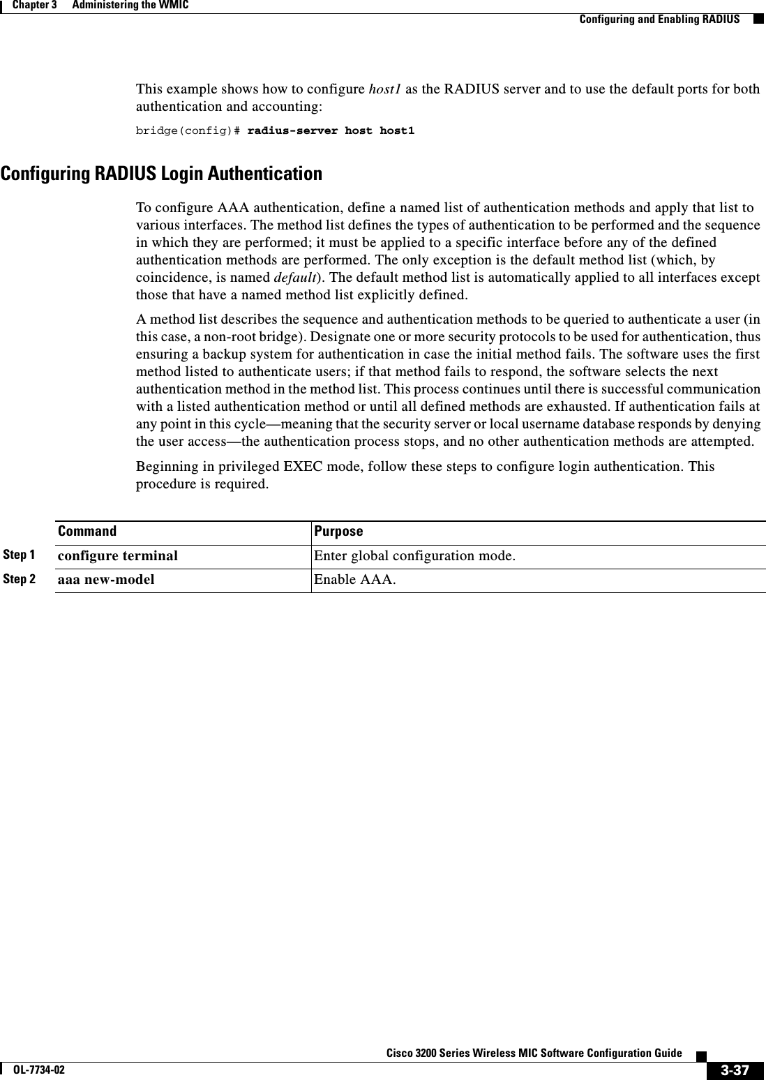
![3-36Cisco 3200 Series Wireless MIC Software Configuration GuideOL-7734-02Chapter 3 Administering the WMICConfiguring and Enabling RADIUSTo remove the specified RADIUS server, use the no radius-server host hostname | ip-address global configuration command. This example shows how to configure one RADIUS server to be used for authentication and another to be used for accounting:bridge(config)# radius-server host 172.29.36.49 auth-port 1612 key rad1bridge(config)# radius-server host 172.20.36.50 acct-port 1618 key rad2Command PurposeStep 1 configure terminal Enter global configuration mode.Step 2 aaa new-model Enable AAA.Step 3 radius-server host {hostname | ip-address} [auth-port port-number][acct-port port-number] [timeoutseconds] [retransmit retries] [keystring]Specify the IP address or host name of the remote RADIUS server host.•(Optional) For auth-port port-number, specify the UDP destination port for authentication requests.•(Optional) For acct-port port-number, specify the UDP destination port for accounting requests.•(Optional) For timeout seconds, specify the time interval that the bridge waits for the RADIUS server to reply before retransmitting. The range is 1 to 1000. This setting overrides the radius-server timeout global configuration command setting. If no timeout is set with the radius-server host command, the setting of the radius-server timeout command is used.•(Optional) For retransmit retries, specify the number of times a RADIUS request is resent to a server if that server is not responding or responding slowly. The range is 1 to 1000. If no retransmit value is set with the radius-server host command, the setting of the radius-server retransmit global configuration command is used.•(Optional) For key string, specify the authentication and encryption key used between the bridge and the RADIUS daemon running on the RADIUS server. Note The key is a text string that must match the encryption key used on the RADIUS server. Always configure the key as the last item in the radius-server host command. Leading spaces are ignored, but spaces within and at the end of the key are used. If you use spaces in your key, do not enclose the key in quotation marks unless the quotation marks are part of the key.To configure the bridge to recognize more than one host entry associated with a single IP address, enter this command as many times as necessary, making sure that each UDP port number is different. The bridge software searches for hosts in the order in which you specify them. Set the timeout, retransmit, and encryption key values to use with the specific RADIUS host.Step 4 end Return to privileged EXEC mode.Step 5 show running-config Verify your entries.Step 6 copy running-config startup-config (Optional) Save your entries in the configuration file.](https://usermanual.wiki/Cisco-Systems/XSCLCR14/User-Guide-558354-Page-88.png)
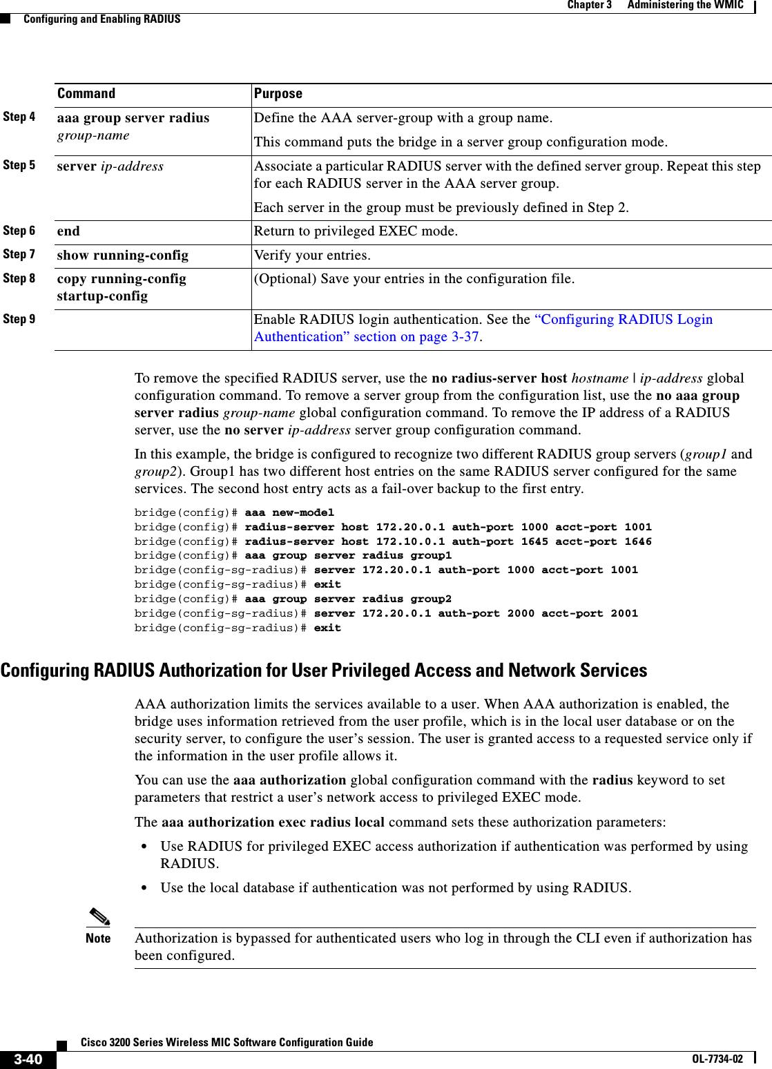
![3-38Cisco 3200 Series Wireless MIC Software Configuration GuideOL-7734-02Chapter 3 Administering the WMICConfiguring and Enabling RADIUSTo disable AAA, use the no aaa new-model global configuration command. To disable AAA authentication, use the no aaa authentication login {default | list-name}method1 [method2...] global configuration command. To either disable RADIUS authentication for logins or to return to the default value, use the no login authentication {default | list-name} line configuration command.Step 3 aaa authentication login {default | list-name}method1 [method2...]Create a login authentication method list.•To create a default list that is used when a named list is not specified in the login authentication command, use the default keyword followed by the methods that are to be used in default situations. The default method list is automatically applied to all interfaces. For more information on list names, click this link: http://www.cisco.com/univercd/cc/td/doc/product/software/ios122/122cgcr/fsecur_c/fsaaa/scfathen.htm#xtocid2•For method1..., specify the actual method the authentication algorithm tries. The additional methods of authentication are used only if the previous method returns an error, not if it fails.Select one of these methods:•line—Use the line password for authentication. You must define a line password before you can use this authentication method. Use the password password line configuration command.•local—Use the local username database for authentication. You must enter username information in the database. Use the usernamepassword global configuration command.•radius—Use RADIUS authentication. You must configure the RADIUS server before you can use this authentication method. For more information, see the “Identifying the RADIUS Server Host”section.Step 4 line [console | tty | vty]line-number[ending-line-number]Enter line configuration mode, and configure the lines to which you want to apply the authentication list.Step 5 login authentication {default | list-name}Apply the authentication list to a line or set of lines.•If you specify default, use the default list created with the aaa authentication login command.•For list-name, specify the list created with the aaa authentication login command.Step 6 radius-server attribute 32 include-in-access-req format %hConfigure the device to send its system name in the NAS_ID attribute for authentication.Step 7 end Return to privileged EXEC mode.Step 8 show running-config Verify your entries.Step 9 copy running-config startup-config (Optional) Save your entries in the configuration file.Command Purpose](https://usermanual.wiki/Cisco-Systems/XSCLCR14/User-Guide-558354-Page-90.png)
![3-39Cisco 3200 Series Wireless MIC Software Configuration GuideOL-7734-02Chapter 3 Administering the WMICConfiguring and Enabling RADIUSDefining AAA Server GroupsConfigure the bridge to use AAA server groups to group existing server hosts for authentication. Select a subset of the configured server hosts and use them for a particular service. The server group is used with a global server-host list, which lists the IP addresses of the selected server hosts. Server groups also can include multiple host entries for the same server if each entry has a unique identifier (the combination of the IP address and UDP port number), allowing different ports to be individually defined as RADIUS hosts providing a specific AAA service. If you configure two different host entries on the same RADIUS server for the same service (such as accounting), the second configured host entry acts as a fail-over backup to the first one.Use the server group server configuration command to associate a particular server with a defined group server. Identify the server by its IP address or identify multiple host instances or entries by using the optional auth-port and acct-port keywords.Beginning in privileged EXEC mode, follow these steps to define the AAA server group and associate a particular RADIUS server with it:Command PurposeStep 1 configure terminal Enter global configuration mode.Step 2 aaa new-model Enable AAA.Step 3 radius-server host {hostname|ip-address} [auth-portport-number] [acct-portport-number] [timeoutseconds] [retransmit retries][key string]Specify the IP address or host name of the remote RADIUS server host.•(Optional) For auth-port port-number, specify the UDP destination port for authentication requests.•(Optional) For acct-port port-number, specify the UDP destination port for accounting requests.•(Optional) For timeout seconds, specify the time interval that the bridge waits for the RADIUS server to reply before retransmitting. The range is 1 to 1000. This setting overrides the radius-server timeout global configuration command setting. If no timeout is set with the radius-server host command, the setting of the radius-server timeout command is used.•(Optional) For retransmit retries, specify the number of times a RADIUS request is resent to a server if that server is not responding or responding slowly. The range is 1 to 1000. If no retransmit value is set with the radius-server hostcommand, the setting of the radius-server retransmit global configuration command is used.•(Optional) For key string, specify the authentication and encryption key used between the bridge and the RADIUS daemon running on the RADIUS server. Note The key is a text string that must match the encryption key used on the RADIUS server. Always configure the key as the last item in the radius-server host command. Leading spaces are ignored, but spaces within and at the end of the key are used. If you use spaces in your key, do not enclose the key in quotation marks unless the quotation marks are part of the key.To configure the bridge to recognize more than one host entry associated with a single IP address, enter this command as many times as necessary, making sure that each UDP port number is different. The bridge software searches for hosts in the order in which you specify them. Set the timeout, retransmit, and encryption key values to use with the specific RADIUS host.](https://usermanual.wiki/Cisco-Systems/XSCLCR14/User-Guide-558354-Page-91.png)
![3-43Cisco 3200 Series Wireless MIC Software Configuration GuideOL-7734-02Chapter 3 Administering the WMICConfiguring and Enabling RADIUSProtocol is a value of the Cisco protocol attribute for a particular type of authorization. Attribute and value are an appropriate AV pair defined in the Cisco TACACS+ specification, and sep is = for mandatory attributes and the asterisk (*) for optional attributes. This allows the full set of features available for TACACS+ authorization to also be used for RADIUS. For example, the following AV pair activates Cisco’s multiple named ip address pools feature during IP authorization (during PPP’s IPCP address assignment):cisco-avpair= ”ip:addr-pool=first“The following example shows how to provide a user logging in from an bridge with immediate access to privileged EXEC commands:cisco-avpair= ”shell:priv-lvl=15“ Other vendors have their own unique vendor IDs, options, and associated VSAs. For more information about vendor IDs and VSAs, refer to RFC 2138, “Remote Authentication Dial-In User Service (RADIUS).” Beginning in privileged EXEC mode, follow these steps to configure the bridge to recognize and use VSAs:For a complete list of RADIUS attributes or more information about VSA 26, refer to the “RADIUS Attributes” appendix in the Cisco IOS Security Configuration Guide for Release 12.2.Configuring the Bridge for Vendor-Proprietary RADIUS Server CommunicationAlthough an IETF draft standard for RADIUS specifies a method for communicating vendor-proprietary information between the bridge and the RADIUS server, some vendors have extended the RADIUS attribute set in a unique way. Cisco IOS software supports a subset of vendor-proprietary RADIUS attributes.As mentioned earlier, to configure RADIUS (whether vendor-proprietary or IETF draft-compliant), you must specify the host running the RADIUS server daemon and the secret text string it shares with the bridge. You specify the RADIUS host and secret text string by using the radius-server global configuration commands.Command PurposeStep 1 configure terminal Enter global configuration mode.Step 2 radius-server vsa send [accounting | authentication]Enable the bridge to recognize and use VSAs as defined by RADIUS IETF attribute 26.•(Optional) Use the accounting keyword to limit the set of recognized vendor-specific attributes to only accounting attributes.•(Optional) Use the authentication keyword to limit the set of recognized vendor-specific attributes to only authentication attributes.If you enter this command without keywords, both accounting and authentication vendor-specific attributes are used.Step 3 end Return to privileged EXEC mode.Step 4 show running-config Verify your settings.Step 5 copy running-config startup-config (Optional) Save your entries in the configuration file.](https://usermanual.wiki/Cisco-Systems/XSCLCR14/User-Guide-558354-Page-95.png)
![3-47Cisco 3200 Series Wireless MIC Software Configuration GuideOL-7734-02Chapter 3 Administering the WMICControlling WMIC Access with TACACS+or until all defined methods are exhausted. If authentication fails at any point in this cycle—meaning that the security server or local username database responds by denying the user access—the authentication process stops, and no other authentication methods are attempted.Identifying the TACACS+ Server Host and Setting the Authentication KeyYou can configure the WMIC to use a single server or AAA server groups to group existing server hosts for authentication. You can group servers to select a subset of the configured server hosts and use them for a particular service. The server group is used with a global server-host list and contains the list of IP addresses of the selected server hosts.Beginning in privileged EXEC mode, follow these steps to identify the IP host or host maintaining TACACS+ server and optionally set the encryption key:To remove the specified TACACS+ server name or address, use the no tacacs-server host hostnameglobal configuration command. To remove a server group from the configuration list, use the no aaa group server tacacs+ group-name global configuration command. To remove the IP address of a TACACS+ server, use the no server ip-address server group subconfiguration command.Command PurposeStep 1 configure terminal Enter global configuration mode.Step 2 tacacs-server host hostname [port integer] [timeout integer] [key string]Identify the IP host or hosts maintaining a TACACS+ server. Enter this command multiple times to create a list of preferred hosts. The software searches for hosts in the order in which you specify them.•For hostname, specify the name or IP address of the host.•(Optional) For port integer, specify a server port number. The default is port 49. The range is 1 to 65535.•(Optional) For timeout integer, specify a time in seconds the WMIC waits for a response from the daemon before it times out and declares an error. The default is 5 seconds. The range is 1 to 1000 seconds.•(Optional) For key string, specify the encryption key for encrypting and decrypting all traffic between the WMIC and the TACACS+ daemon. You must configure the same key on the TACACS+ daemon for encryption to be successful.Step 3 aaa new-model Enable AAA.Step 4 aaa group server tacacs+ group-name (Optional) Define the AAA server-group with a group name.This command puts the WMIC in a server group subconfiguration mode.Step 5 server ip-address (Optional) Associate a particular TACACS+ server with the defined server group. Repeat this step for each TACACS+ server in the AAA server group.Each server in the group must be previously defined in Step 2.Step 6 end Return to privileged EXEC mode.Step 7 show tacacs Verify your entries.Step 8 copy running-config startup-config (Optional) Save your entries in the configuration file.](https://usermanual.wiki/Cisco-Systems/XSCLCR14/User-Guide-558354-Page-99.png)
![3-48Cisco 3200 Series Wireless MIC Software Configuration GuideOL-7734-02Chapter 3 Administering the WMICControlling WMIC Access with TACACS+Configuring TACACS+ Login AuthenticationTo configure AAA authentication, you define a named list of authentication methods and then apply that list to various interfaces. The method list defines the types of authentication to be performed and the sequence in which they are performed; it must be applied to a specific interface before any of the defined authentication methods are performed. The only exception is the default method list (which, by coincidence, is named default). The default method list is automatically applied to all interfaces except those that have a named method list explicitly defined. A defined method list overrides the default method list.A method list describes the sequence and authentication methods to be queried to authenticate an administrator. You can designate one or more security protocols to be used for authentication, thus ensuring a backup system for authentication in case the initial method fails. The software uses the first method listed to authenticate users; if that method fails to respond, the software selects the next authentication method in the method list. This process continues until there is successful communication with a listed authentication method or until all defined methods are exhausted. If authentication fails at any point in this cycle—meaning that the security server or local username database responds by denying the administrator access—the authentication process stops, and no other authentication methods are attempted.Beginning in privileged EXEC mode, follow these steps to configure login authentication. This procedure is required.Command PurposeStep 1 configure terminal Enter global configuration mode.Step 2 aaa new-model Enable AAA.Step 3 aaa authentication login {default | list-name}method1 [method2...]Create a login authentication method list.•To create a default list that is used when a named list is not specified in the login authentication command, use the default keyword followed by the methods that are to be used in default situations. The default method list is automatically applied to all interfaces.•For list-name, specify a character string to name the list you are creating. •For method1..., specify the actual method the authentication algorithm tries. The additional methods of authentication are used only if the previous method returns an error, not if it fails.Select one of these methods:•local—Use the local username database for authentication. You must enter username information into the database. Use the usernamepassword global configuration command.•tacacs+—Use TACACS+ authentication. You must configure the TACACS+ server before you can use this authentication method.Step 4 line [console | tty | vty]line-number[ending-line-number]Enter line configuration mode, and configure the lines to which you want to apply the authentication list.](https://usermanual.wiki/Cisco-Systems/XSCLCR14/User-Guide-558354-Page-100.png)
![3-49Cisco 3200 Series Wireless MIC Software Configuration GuideOL-7734-02Chapter 3 Administering the WMICControlling WMIC Access with TACACS+To disable AAA, use the no aaa new-model global configuration command. To disable AAA authentication, use the no aaa authentication login {default | list-name}method1 [method2...] global configuration command. To either disable TACACS+ authentication for logins or to return to the default value, use the no login authentication {default | list-name} line configuration command.Configuring TACACS+ Authorization for Privileged EXEC Access and Network ServicesAAA authorization limits the services available to a user. When AAA authorization is enabled, the WMIC uses information retrieved from the user’s profile, which is located either in the local user database or on the security server, to configure the user’s session. The user is granted access to a requested service only if the information in the user profile allows it.You can use the aaa authorization global configuration command with the tacacs+ keyword to set parameters that restrict a user’s network access to privileged EXEC mode. The aaa authorization exec tacacs+ local command sets these authorization parameters:•Use TACACS+ for privileged EXEC access authorization if authentication was performed by using TAC ACS+.•Use the local database if authentication was not performed by using TACACS+.Note Authorization is bypassed for authenticated users who log in through the CLI even if authorization has been configured.Beginning in privileged EXEC mode, follow these steps to specify TACACS+ authorization for privileged EXEC access and network services: Step 5 login authentication {default | list-name}Apply the authentication list to a line or set of lines.•If you specify default, use the default list created with the aaa authentication login command.•For list-name, specify the list created with the aaa authentication login command.Step 6 end Return to privileged EXEC mode.Step 7 show running-config Verify your entries.Step 8 copy running-config startup-config (Optional) Save your entries in the configuration file.Command PurposeCommand PurposeStep 1 configure terminal Enter global configuration mode.Step 2 aaa authorization network tacacs+ Configure the WMIC for user TACACS+ authorization for all network-related service requests.Step 3 aaa authorization exec tacacs+ Configure the WMIC for user TACACS+ authorization to determine if the user has privileged EXEC access. The exec keyword might return user profile information (such as autocommand information).](https://usermanual.wiki/Cisco-Systems/XSCLCR14/User-Guide-558354-Page-101.png)
![3-51Cisco 3200 Series Wireless MIC Software Configuration GuideOL-7734-02Chapter 3 Administering the WMICConfiguring the WMIC for Local Authentication and AuthorizationConfiguring the WMIC for Local Authentication and AuthorizationYou can configure AAA to operate without a server by setting the WMIC to implement AAA in local mode. The WMIC then handles authentication and authorization. No accounting is available in this configuration.Beginning in privileged EXEC mode, follow these steps to configure the WMIC for local AAA:To disable AAA, use the no aaa new-model global configuration command. To disable authorization, use the no aaa authorization {network | exec}method1 global configuration command. Command PurposeStep 1 configure terminal Enter global configuration mode.Step 2 aaa new-model Enable AAA.Step 3 aaa authentication login default local Set the login authentication to use the local username database. The default keyword applies the local user database authentication to all interfaces.Step 4 aaa authorization exec local Configure user AAA authorization to determine if the user is allowed to run an EXEC shell by checking the local database.Step 5 aaa authorization network local Configure user AAA authorization for all network-related service requests.Step 6 username name [privilege level]{password encryption-type password}Enter the local database, and establish a username-based authentication system.Repeat this command for each user.•For name, specify the user ID as one word. Spaces and quotation marks are not allowed.•(Optional) For level, specify the privilege level the user has after gaining access. The range is 0 to 15. Level 15 gives privileged EXEC mode access. Level 0 gives user EXEC mode access.•For encryption-type, enter 0 to specify that an unencrypted password follows. Enter 7 to specify that a hidden password follows.•For password, specify the password the user must enter to gain access to the WMIC. The password must be from 1 to 25 characters, can contain embedded spaces, and must be the last option specified in the username command.Step 7 end Return to privileged EXEC mode.Step 8 show running-config Verify your entries.Step 9 copy running-config startup-config (Optional) Save your entries in the configuration file.](https://usermanual.wiki/Cisco-Systems/XSCLCR14/User-Guide-558354-Page-103.png)

![4-2Cisco 3200 Series Wireless MIC Software Configuration GuideOL-7734-02Chapter 4 Configuring Radio SettingsDisabling and Enabling the Radio InterfaceDisabling and Enabling the Radio InterfaceThe WMIC radio is enabled by default. Beginning in privileged EXEC mode, follow these steps to disable the WMIC radio:Use the no form of the shutdown command to enable the radio port. Configuring the Role in Radio NetworkYou can configure your WMIC as a root bridge, non-root bridge, access point, or workgroup bridge. (Chapter 1, “Overview” describes the various WMIC radio network roles.) Beginning in privileged EXEC mode, follow these steps to set the WMIC radio network role:Command PurposeStep 1 configure terminal Enter global configuration mode.Step 2 interface dot11radio 0 Enter interface configuration mode for the radio interface. Step 3 shutdown Disable the radio port.Step 4 end Return to privileged EXEC mode.Step 5 copy running-config startup-config (Optional) Save your entries in the configuration file.Command PurposeStep 1 configure terminal Enter global configuration mode.Step 2 interface dot11radio 0 Enter interface configuration mode for the radio interface. Step 3 station-role {root [ap-only] | non-root |workgroup-bridge |install [automatic |root |non-root]}Set the WMIC role.•Bridge—root, non-root, or install modes. In root mode, the access point function is automatically enabled allowing client devices to associate.•Access point—root ap-only mode•Workgroup bridge—workgroup bridge modeStep 4 mobile station (Optional) Use this command to configure a non-root bridge or workgroup bridge as a mobile station. When this feature is enabled the bridge scans for a new parent association when it encounters a poor Received Signal Strength Indicator (RSSI), excessive radio interference, or a high frame-loss percentage. Using these criteria, the WMIC searches for a new root association and roams to a new root bridge before it loses its current association. When the mobile station setting is disabled (the default setting) the WMIC does not search for a new association until it loses its current association.Step 5 end Return to privileged EXEC mode.Step 6 copy running-config startup-config (Optional) Save your entries in the configuration file.](https://usermanual.wiki/Cisco-Systems/XSCLCR14/User-Guide-558354-Page-108.png)
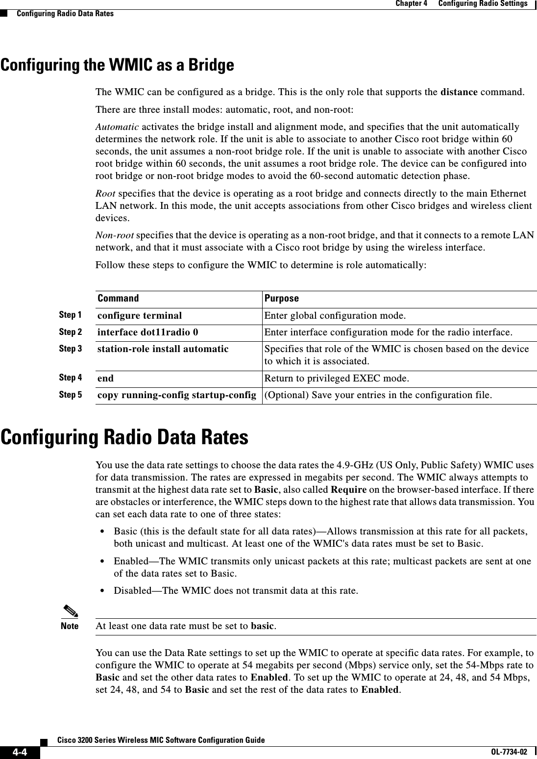
![4-5Cisco 3200 Series Wireless MIC Software Configuration GuideOL-7734-02Chapter 4 Configuring Radio SettingsConfiguring Radio Data RatesYou can also configure the WMIC to set the data rates automatically to optimize either range or throughput. When you enter range for the data rate setting, the WMIC sets the 6-Mbps rate to basic and the other rates to enabled if you are configuring a 2.4-GHz WMIC or a 4.9-GHz WMIC.If you are configuring a 4.9-GHz WMIC set to 5-MHz spacing, the WMIC sets the 1.5- Mbps rate to basic and the other rates to enable. If you are configuring a 4.9-GHz WMIC set to 10-MHz spacing, the WMIC sets the 3.0-Mbps rate to basic and the other rates to enable. If you enter throughput for the data rate setting, the WMIC sets all data rates to basic. Enter default to set the data rates to factory defaultsBeginning in privileged EXEC mode, follow these steps to configure the radio data rates:Command PurposeStep 1 configure terminal Enter global configuration mode.Step 2 interface dot11radio 0 Enter interface configuration mode for the radio interface. Step 3 speed{[1.0] [2.0] [5.5] [6.0] [9.0] [11.0][12.0] [18.0] [24.0] [36.0] [48.0][54.0] [basic-1.0] [basic-2.0][basic-5.5] [basic-6.0] [basic-9.0][basic-11.0] [basic-12.0][basic-18.0] [basic-24.0][basic-36.0] [basic-48.0][basic-54.0] | range | throughput | default }Set each data rate to basic or enabled, or enter range to optimize the range or throughput to optimize the throughput.If you are entering the speed for a 2.4-GHz WMIC, enter 1.0,2.0,5.5,6.0,9.0,11.0,12.0,18.0,24.0,36.0,48.0, and54.0 to set these data rates to enabled.If you are entering the speed for a 4.9-GHz WMIC:With 5-MHz spacing, enter a speed of 1.5, 2.25, 3.0, 4.5, 6.0, 9.0, 12.0, or 13.5. With 10-MHz spacing, enter a speed of 3.0, 4.5, 6.0, 9.0, 12.0, 18.0, 24.0, or 27.0.Enter basic-1.0,basic-2.0, basic-5.5, basic-6.0,basic-9.0,basic-11.0,basic-12.0,basic-18.0,basic-24.0,basic-36.0,basic-48.0, and basic-54.0 to set these data rates to basic.Note The client must support the basic rate that you select or it cannot associate to the WMIC. If you select 12 Mbps or higher for the basic data rate on the 802.11g radio, 802.11b client devices cannot associate to the WMIC’s 802.11g radio.•(Optional) Enter range or throughput to automatically optimize radio range or throughput. When you enter range, The WMIC sets the lowest data rate to basic and the other rates to enabled. When you enter throughput, the WMIC sets all data rates to basic.(Optional) The default option sets data rates 1, 2, 5.5, 6, 11, 12, and 24 to basic, and data rates 9, 18, 36, 48, and 54 to enabled. These data rate settings allow both 802.11b and 802.11g client devices to associate to the WMIC’s 802.11g radio.Step 4 end Return to privileged EXEC mode.Step 5 copy running-config startup-config (Optional) Save your entries in the configuration file.](https://usermanual.wiki/Cisco-Systems/XSCLCR14/User-Guide-558354-Page-111.png)
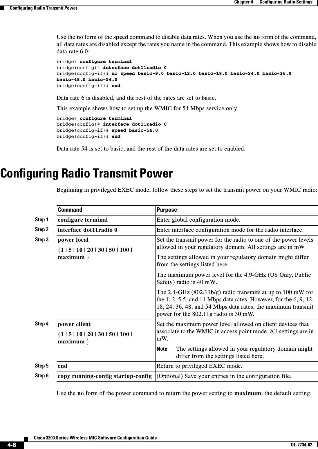
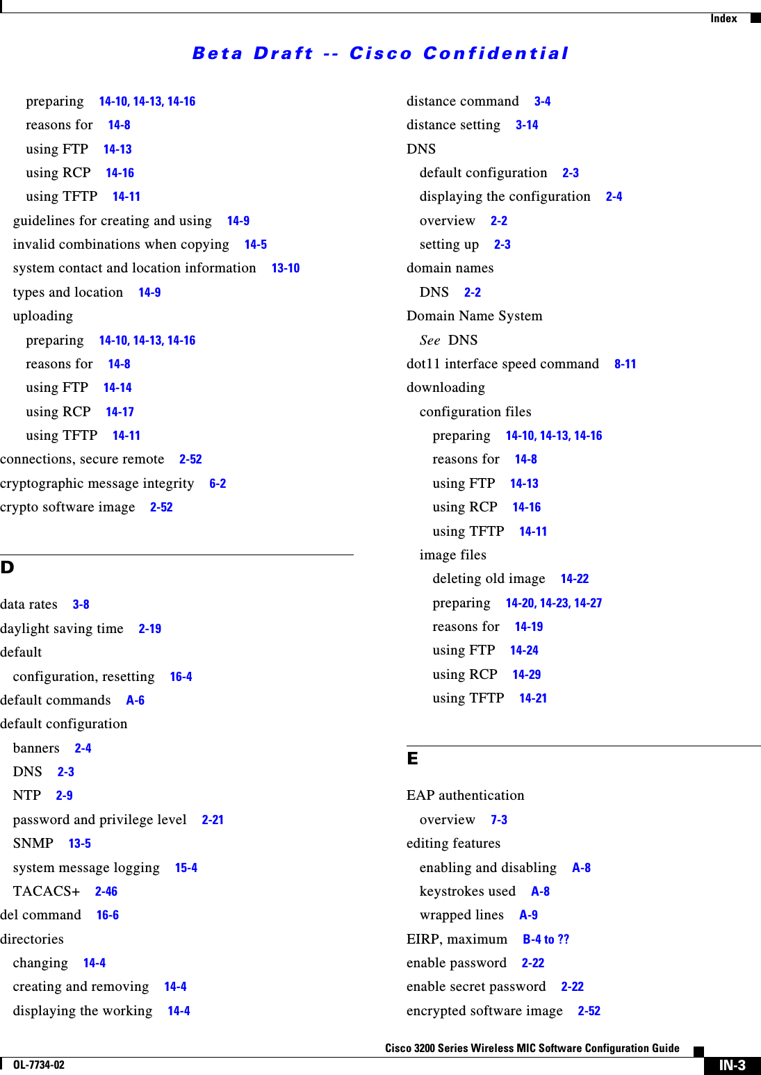
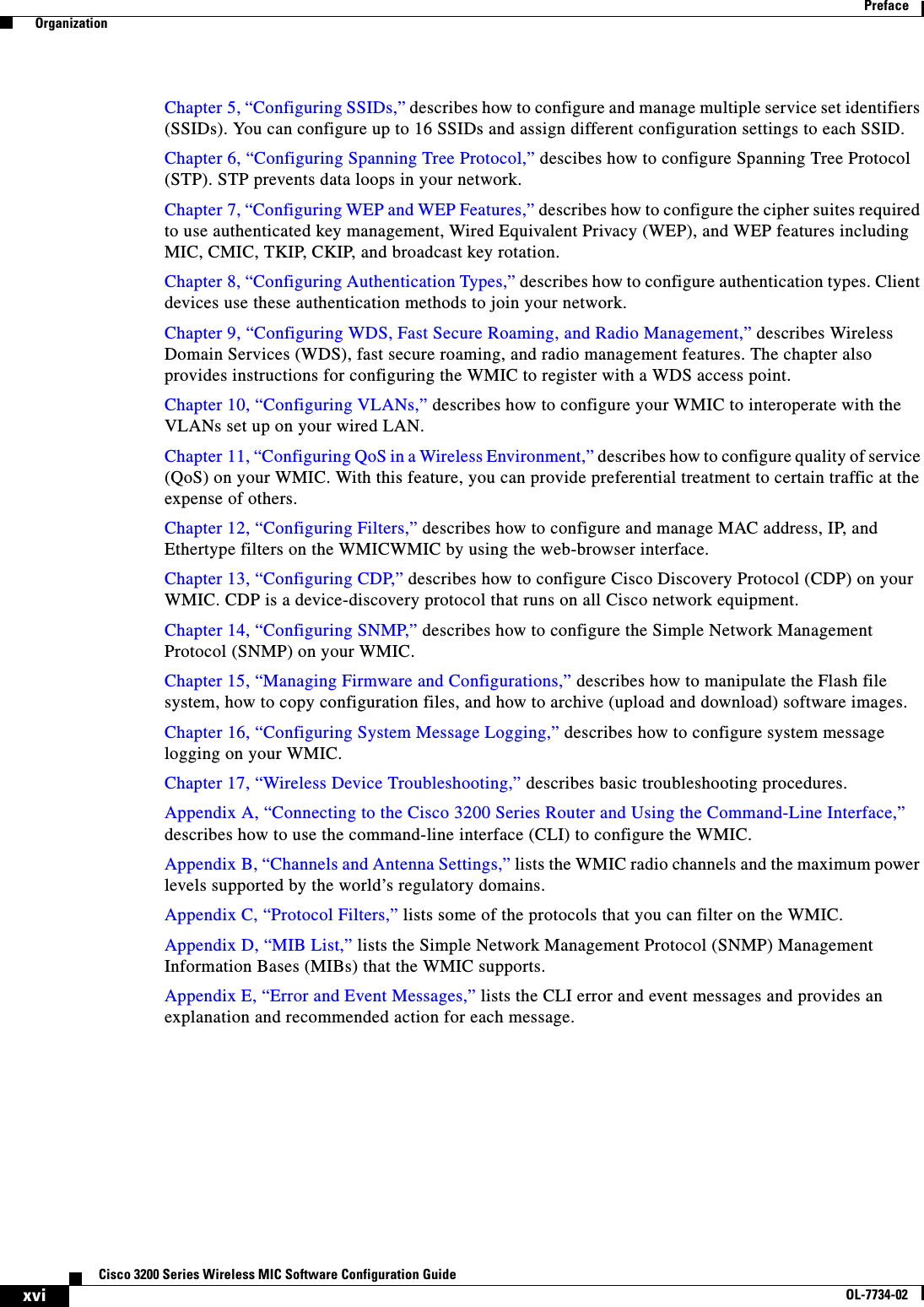
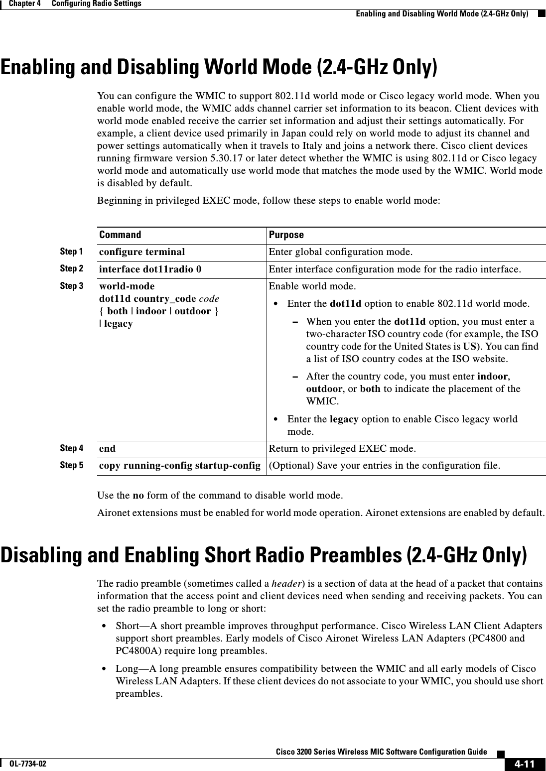
![4-9Cisco 3200 Series Wireless MIC Software Configuration GuideOL-7734-02Chapter 4 Configuring Radio SettingsConfiguring Radio Channel Settingsspacing channel User Interface CommandUse the spacing privileged EXEC command to define allowable channels and center frequencies for the 4.9-GHz WMIC. Use no form of this command to reset the channels and center frequencies to defaults. Released in 12.3(JK).spacing <baseband_no> [channel {centerFrequency | channel_number | least-congested}]Note The channel command is not available when this command is entered in the configuration.Syntax Description4.5 BPSK 19 -93 46 QPSK 19 -92 69 QPSK 19 -91 612 16-QAM 19 -87 1118 16-QAM 18 -84 1124 64-QAM 16 -78 2027 64-QAM 15 -75 205 MHz Channelization1.5 BPSK 19 -97 42.25 BPSK 19 -96 43 QPSK 19 -95 64.5 QPSK 19 -94 66 16-QAM 19 -90 119 16-QAM 18 -87 1112 64-QAM 16 -81 2013.5 64-QAM 15 -78 20 Table 4-1 Radio Frequency Data Ratesbaseband_no Specifies the channel spacing in megahertz on the desired channel band. The frequency is either 5-MHz wide or 10-MHz wide.centerFrequency Specifies the center frequency in megahertz of the desired channel band. Supported frequencies are listed in Table 4-2.channel_number Supported channel number. Supported channels are listed in Table 4-2.least-congested Automatically scan for the best frequency.](https://usermanual.wiki/Cisco-Systems/XSCLCR14/User-Guide-558354-Page-115.png)


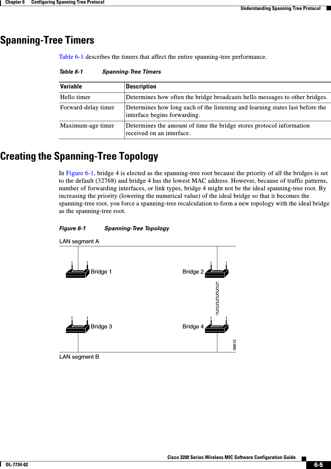
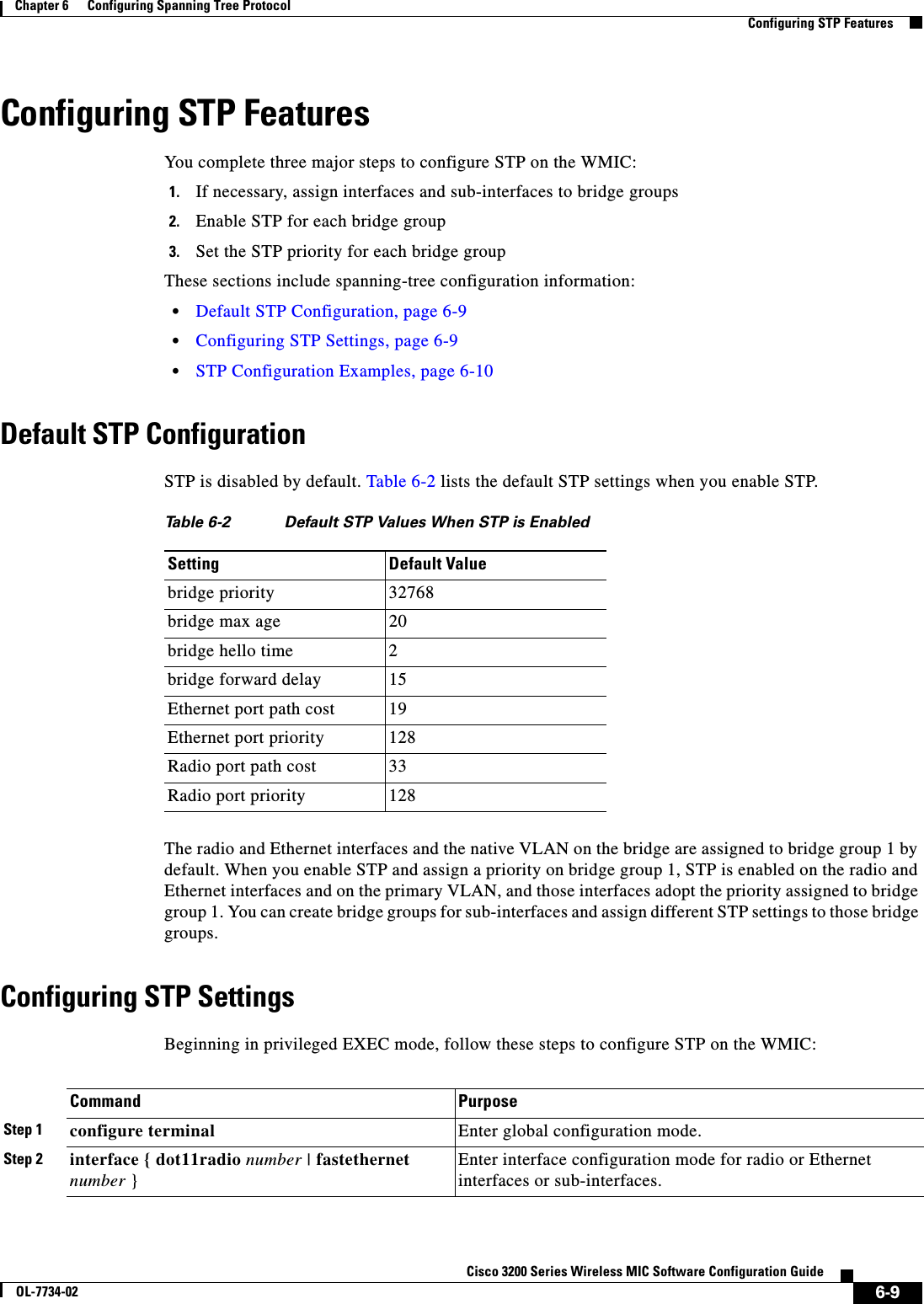
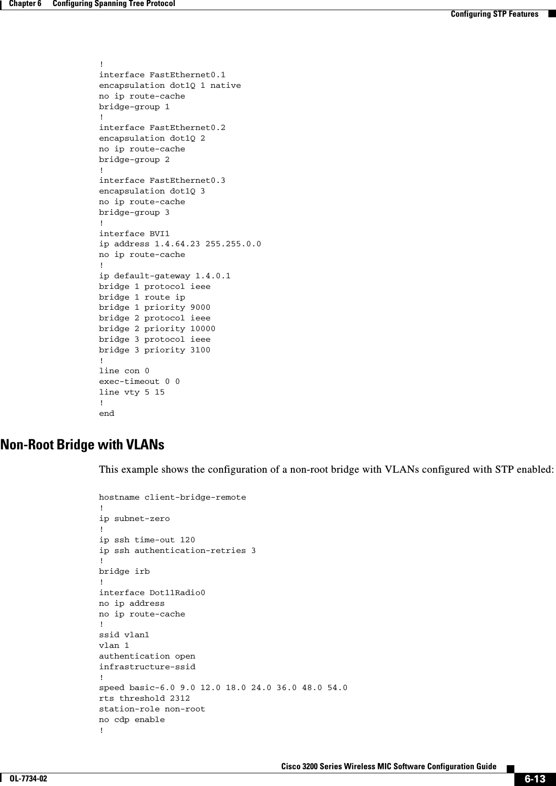
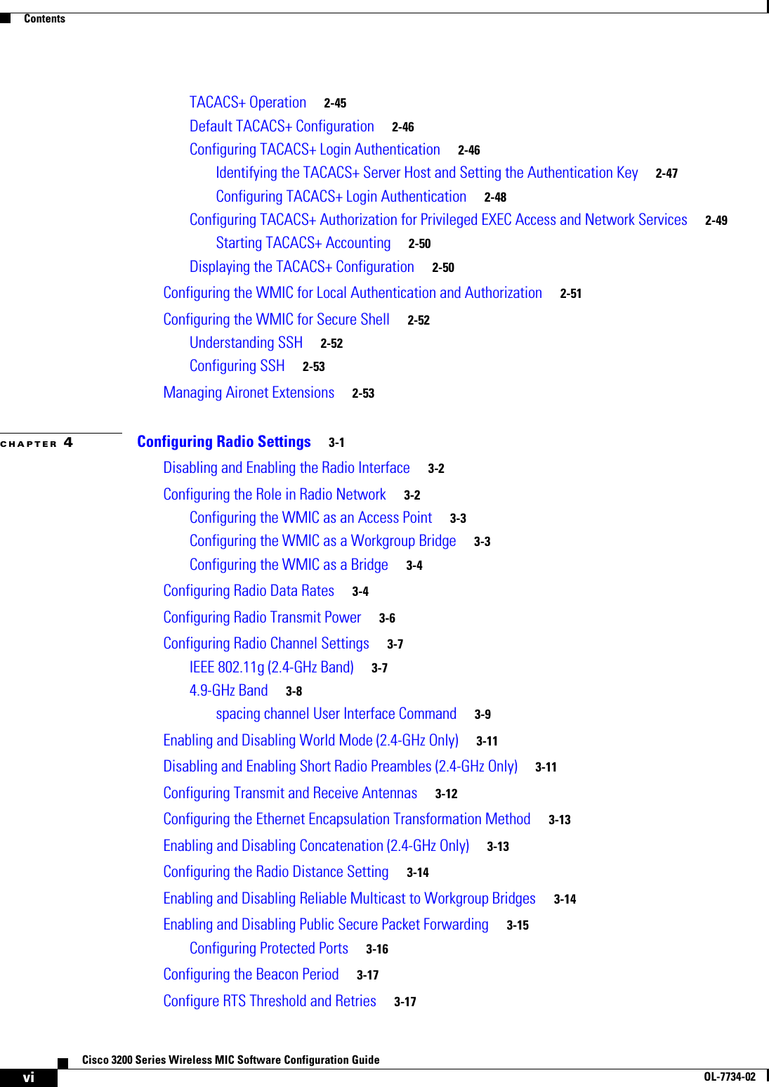
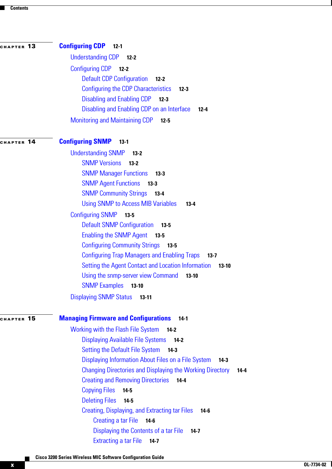
![6-15Cisco 3200 Series Wireless MIC Software Configuration GuideOL-7734-02Chapter 6 Configuring Spanning Tree ProtocolDisplaying Spanning-Tree StatusDisplaying Spanning-Tree StatusTo display the spanning-tree status, use one or more of the privileged EXEC commands in Table 6-3:For information about other keywords for the show spanning-tree privileged EXEC command, refer to the Cisco IOS Command Reference for Cisco Access Points and Bridges.Table 6-3 Commands for Displaying Spanning-Tree StatusbridgeCommand Purposeshow spanning-tree Displays information on your network’s spanning tree.show spanning-tree blocked-ports Displays a list of blocked ports on this device.show spanning-tree bridge Displays status and configuration of this bridge.show spanning-tree active Displays spanning-tree information on active interfaces only.show spanning-tree root Displays a detailed summary of information on the spanning-tree root.show spanning-tree interface interface-id Displays spanning-tree information for the specified interface.show spanning-tree summary [totals] Displays a summary of port states or displays the total lines of the STP state section.](https://usermanual.wiki/Cisco-Systems/XSCLCR14/User-Guide-558354-Page-145.png)

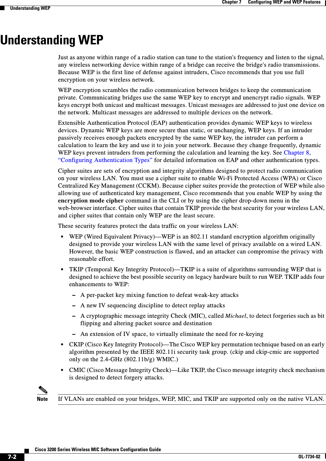
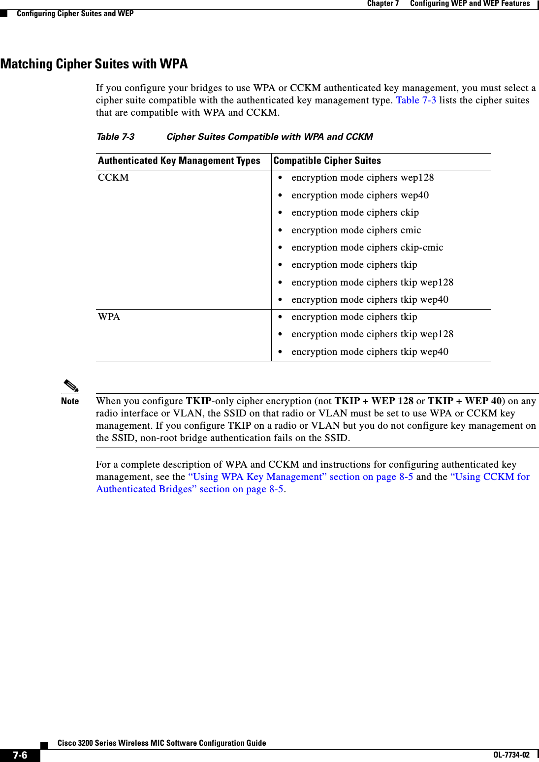
![7-3Cisco 3200 Series Wireless MIC Software Configuration GuideOL-7734-02Chapter 7 Configuring WEP and WEP FeaturesConfiguring Cipher Suites and WEPConfiguring Cipher Suites and WEPThese sections describe how to configure cipher suites, WEP and additional WEP features such as MIC and TKIP:•Creating WEP Keys, page 7-3•Enabling Cipher Suites and WEP, page 7-5WEP, TKIP, and MIC are disabled by default.Creating WEP KeysBeginning in privileged EXEC mode, follow these steps to create a WEP key and set the key properties:This example shows how to create a 128-bit WEP key in slot 2 for VLAN 1 and sets the key as the transmit key:bridge# configure terminalbridge(config)# configure interface dot11radio 0bridge(config-if)# encryption vlan 1 key 2 size 128 12345678901234567890123456 transmit-keybridge(config-if)# endCommand PurposeStep 1 configure terminal Enter global configuration mode.Step 2 interface dot11radio 0 Enter interface configuration mode for the radio interface.Step 3 encryption [vlan vlan-id]key 1-4size {40 | 128 } encryption-key[transmit-key]Create a WEP key and set up its properties.•(Optional) Select the VLAN for which you want to create a key. WEP, MIC, and TKIP are supported only on the native VLAN.•Name the key slot in which this WEP key resides. You can assign up to 4 WEP keys for each VLAN, but key slot 4 is reserved for the session key.•Enter the key and set the size of the key, either 40-bit or 128-bit. 40-bit keys contain 10 hexadecimal digits; 128-bit keys contain 26 hexadecimal digits. •(Optional) Set this key as the transmit key. The key in slot 2 is the transmit key by default. If you enable WEP with MIC, use the same WEP key as the transmit key in the same key slot on both root and non-root bridges.Step 4 end Return to privileged EXEC mode.Step 5 copy running-config startup-config (Optional) Save your entries in the configuration file.](https://usermanual.wiki/Cisco-Systems/XSCLCR14/User-Guide-558354-Page-149.png)
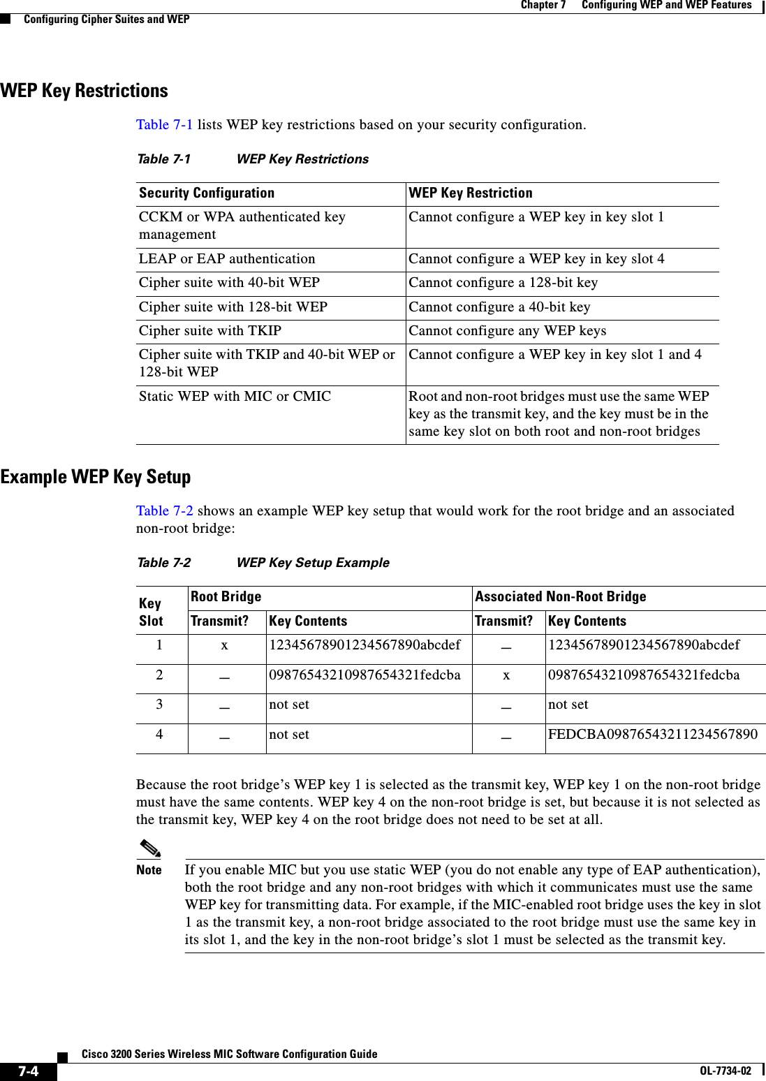
![7-5Cisco 3200 Series Wireless MIC Software Configuration GuideOL-7734-02Chapter 7 Configuring WEP and WEP FeaturesConfiguring Cipher Suites and WEPEnabling Cipher Suites and WEPBeginning in privileged EXEC mode, follow these steps to enable a cipher suite:Use the no form of the encryption command to disable a cipher suite.This example sets up a cipher suite for VLAN 1 that enables CKIP, CMIC, and 128-bit WEP.bridge# configure terminalbridge(config)# configure interface dot11radio 0bridge(config-if)# encryption vlan 1 mode ciphers ckip-cmic wep128bridge(config-if)# endCommand PurposeStep 1 configure terminal Enter global configuration mode.Step 2 interface dot11radio 0 Enter interface configuration mode for the radio interface. Step 3 encryption[vlan vlan-id]mode ciphers{[aes-ccm | ckip | cmic | ckip-cmic |tkip]}{[wep128 | wep40]}Enable a cipher suite containing the WEP protection you need. Table 7-3 lists guidelines for selecting a cipher suite that matches the type of authenticated key management you configure.•(Optional) Select the VLAN for which you want to enable WEP and WEP features.•Set the cipher options and WEP level. You can combine TKIP with 128-bit or 40-bit WEP.Note If you enable a cipher suite with two elements (such as TKIP and 128-bit WEP), the second cipher becomes the group cipher.Note You can also use the encryption mode wep command to set up static WEP. However, you should use encryption mode wep only if none of the non-root bridges that associate to the root bridge are capable of key management. See the Cisco IOS Command Reference for Cisco Access Points and Bridges for a detailed description of the encryption mode wepcommand.Note When you configure TKIP-only cipher encryption (not TKIP + WEP 128 or TKIP + WEP 40) on any radio interface or VLAN, the SSID on that radio or VLAN must be set to use WPA or CCKM key management. If you configure TKIP on a radio or VLAN but you do not configure key management on the SSID, non-root bridge authentication fails on the SSID.Note ckip and ckip-cmic are supported only on the 2.4-GHz (802.11b/g) WMIC.Step 4 end Return to privileged EXEC mode.Step 5 copy running-config startup-config (Optional) Save your entries in the configuration file.](https://usermanual.wiki/Cisco-Systems/XSCLCR14/User-Guide-558354-Page-151.png)
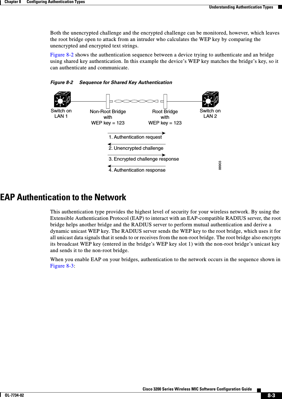
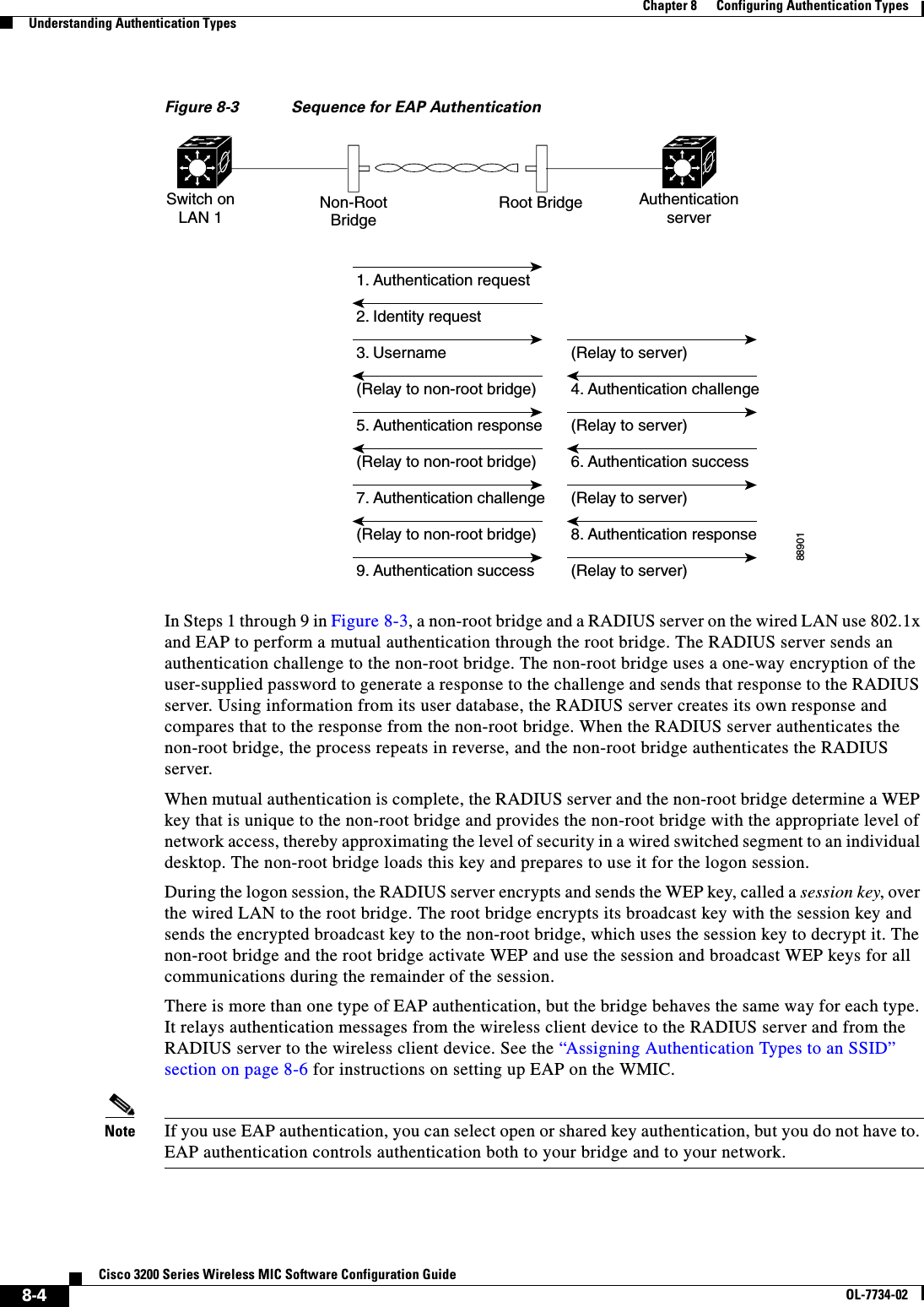
 Set the authentication type to open for this SSID. Open authentication allows any bridge to authenticate and then attempt to communicate with the WMIC. •(Optional) Set the SSID’s authentication type to open with EAP authentication. The WMIC forces all other bridges to perform EAP authentication before they are allowed to join the network. For list-name, specify the authentication method list. Note A bridge configured for EAP authentication forces all bridges that associate to perform EAP authentication. Bridges that do not use EAP cannot communicate with the bridge.Step 5 authentication shared[eap list-name](Optional) Set the authentication type for the SSID to shared key.Note Because of shared key's security flaws, Cisco recommends that you avoid using it.•(Optional) Set the SSID’s authentication type to shared key with EAP authentication. For list-name, specify the authentication method list.](https://usermanual.wiki/Cisco-Systems/XSCLCR14/User-Guide-558354-Page-158.png)
![8-7Cisco 3200 Series Wireless MIC Software Configuration GuideOL-7734-02Chapter 8 Configuring Authentication TypesConfiguring Authentication TypesUse the no form of the SSID commands to disable the SSID or to disable SSID features.This example sets the authentication type for the SSID bridgeman to open with EAP authentication. Bridges using the SSID bridgeman attempt EAP authentication using a server named adam.bridge# configure terminalbridge(config)# configure interface dot11radio 0bridge(config-if)# ssid bridgemanbridge(config-ssid)# authentication open eap adambridge(config-ssid)# endStep 6 authentication network-eaplist-name(Optional) Set the authentication type for the SSID to use LEAP for authentication and key distribution. Cisco bridges only support LEAP, while other wireless clients may support other EAP methods such as EAP, PEAP, or TLS.Step 7 authentication key-management{[wpa][cckm]} [optional](Optional) Set the authentication type for the SSID to WPA, CCKM, or both. If you use the optional keyword, non-root bridges not configured for WPA or CCKM can use this SSID. If you do not use the optional keyword, only WPA or CCKM bridges are allowed to use the SSID.To enable CCKM for an SSID, you must also enable Network-EAP authentication. To enable WPA for an SSID, you must also enable Open authentication or Network-EAP or both.Note Only 802.11b and 802.11g radios support WPA and CCKM simultaneously.Note Before you can enable CCKM or WPA, you must set the encryption mode for the SSID’s VLAN to one of the cipher suite options. To enable both CCKM and WPA, you must set the encryption mode to a cipher suite that includes TKIP. See the “Enabling Cipher Suites and WEP” section on page 7-5 for instructions on configuring the VLAN encryption mode.Note If you enable WPA for an SSID without a pre-shared key, the key management type is WPA. If you enable WPA with a pre-shared key, the key management type is WPA-PSK. See the “Configuring Additional WPA Settings” section on page 8-9 for instructions on configuring a pre-shared key.Note To support CCKM, your root bridge must interact with the WDS device on your network. See the “Configuring the Root Bridge to Interact with the WDS Device” section on page 8-8 for instructions on configuring your root bridge to interact with your WDS device.Step 8 end Return to privileged EXEC mode.Step 9 copy running-config startup-config (Optional) Save your entries in the configuration file.Command Purpose](https://usermanual.wiki/Cisco-Systems/XSCLCR14/User-Guide-558354-Page-159.png)
![8-9Cisco 3200 Series Wireless MIC Software Configuration GuideOL-7734-02Chapter 8 Configuring Authentication TypesConfiguring Authentication TypesConfiguring Additional WPA SettingsUse two optional settings to configure a pre-shared key on the bridge and adjust the frequency of group key updates.Setting a Pre-Shared KeyTo support WPA on a wireless LAN where 802.1x-based authentication is not available, you must configure a pre-shared key on the bridge. You can enter the pre-shared key as ASCII or hexadecimal characters. If you enter the key as ASCII characters, you enter between 8 and 63 characters, and the bridge expands the key using the process described in the Password-based Cryptography Standard(RFC2898). If you enter the key as hexadecimal characters, you must enter 64 hexadecimal characters.Configuring Group Key UpdatesIn the last step in the WPA process, the root bridge distributes a group key to the authenticated non-root bridge. You can use these optional settings to configure the root bridge to change and distribute the group key based on association and disassociation of non-root bridges:•Membership termination—the root bridge generates and distributes a new group key when any authenticated non-root bridge disassociates from the root bridge. This feature keeps the group key private for associated bridges.•Capability change—the root bridge generates and distributes a dynamic group key when the last non-key management (static WEP) non-root bridge disassociates, and it distributes the statically configured WEP key when the first non-key management (static WEP) non-root bridge authenticates. In WPA migration mode, this feature significantly improves the security of key-management capable clients when there are no static-WEP bridges associated to the root bridge.Beginning in privileged EXEC mode, follow these steps to configure a WPA pre-shared key and group key update options:This example shows how to configure a pre-shared key for non-root bridges using WPA and static WEP, with group key update options:bridge# configure terminalbridge(config)# configure interface dot11radio 0Command PurposeStep 1 configure terminal Enter global configuration mode.Step 2 interface dot11radio 0 Enter interface configuration mode for the radio interface. Step 3 ssid ssid-string Enter SSID configuration mode for the SSID. Step 4 wpa-psk { hex | ascii } [ 0 | 7 ] encryption-keyEnter a pre-shared key for bridges using WPA that also use static WEP keys.Enter the key using either hexadecimal or ASCII characters. If you use hexadecimal, you must enter 64 hexadecimal characters to complete the 256-bit key. If you use ASCII, you must enter a minimum of 8 letters, numbers, or symbols, and the bridge expands the key for you. You can enter a maximum of 63 ASCII characters.Step 5 end Return to privileged EXEC mode.Step 6 copy running-config startup-config (Optional) Save your entries in the configuration file.](https://usermanual.wiki/Cisco-Systems/XSCLCR14/User-Guide-558354-Page-161.png)
![8-10Cisco 3200 Series Wireless MIC Software Configuration GuideOL-7734-02Chapter 8 Configuring Authentication TypesConfiguring Authentication Typesbridge(config-if)# ssid batmanbridge(config-ssid)# wpa-psk ascii batmobile65bridge(config-ssid)# endConfiguring Authentication Holdoffs, Timeouts, and IntervalsBeginning in privileged EXEC mode, follow these steps to configure holdoff times, reauthentication periods, and authentication timeouts for non-root bridges authenticating through your root bridge:Use the no form of these commands to reset the values to default settings. Setting Up a Non-Root Bridge as a LEAP ClientYou can set up a non-root bridge to authenticate to your network like other wireless client devices. After you provide a network username and password for the non-root bridge, it authenticates to your network using LEAP, Cisco's wireless authentication method, and receives and uses dynamic WEP keys. Setting up a non-root bridge as a LEAP client requires three major steps:1. Create an authentication username and password for the non-root bridge on your authentication server.2. Configure LEAP authentication on the root bridge to which the non-root bridge associates. 3. Configure the non-root bridge to act as a LEAP client. Command PurposeStep 1 configure terminal Enter global configuration mode.Step 2 dot11 holdoff-time seconds Enter the number of seconds a root bridge must wait before it disassociates and idle client. Enter a value from 1 to 65555 seconds.Step 3 interface dot11radio 0 Enter interface configuration mode for the radio interface. Step 4 dot1x client-timeout seconds Enter the number of seconds the bridge should wait for a reply from a non-root bridge attempting to authenticate before the authentication fails. Enter a value from 1 to 65555 seconds.Step 5 dot1x reauth-period seconds [server]Enter the interval in seconds that the WMIC waits before forcing an authenticated non-root bridge to reauthenticate.•(Optional) Enter the server keyword to configure the bridge to use the reauthentication period specified by the authentication server. If you use this option, configure your authentication server with RADIUS attribute 27, Session-Timeout. This attribute sets the maximum number of seconds of service to be provided to the non-root bridge before termination of the session or prompt. The server sends this attribute to the root bridge when a non-root bridge performs EAP authentication.Step 6 end Return to privileged EXEC mode.Step 7 copy running-config startup-config (Optional) Save your entries in the configuration file.](https://usermanual.wiki/Cisco-Systems/XSCLCR14/User-Guide-558354-Page-162.png)
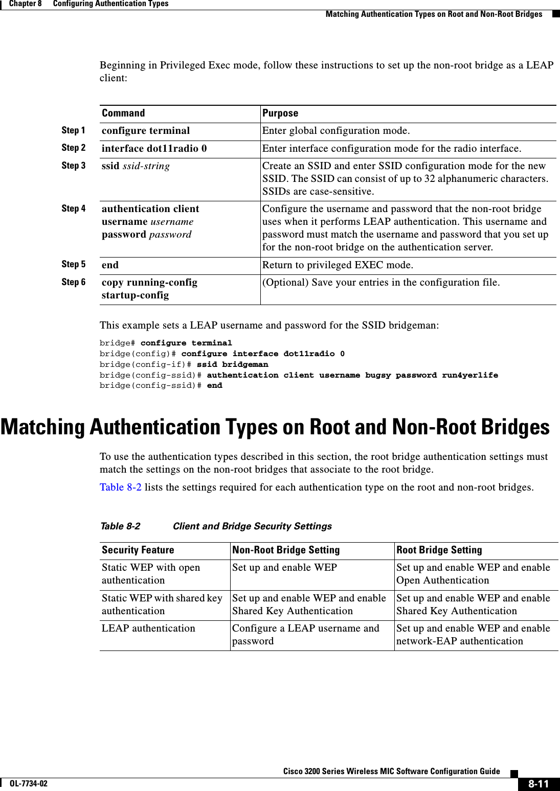
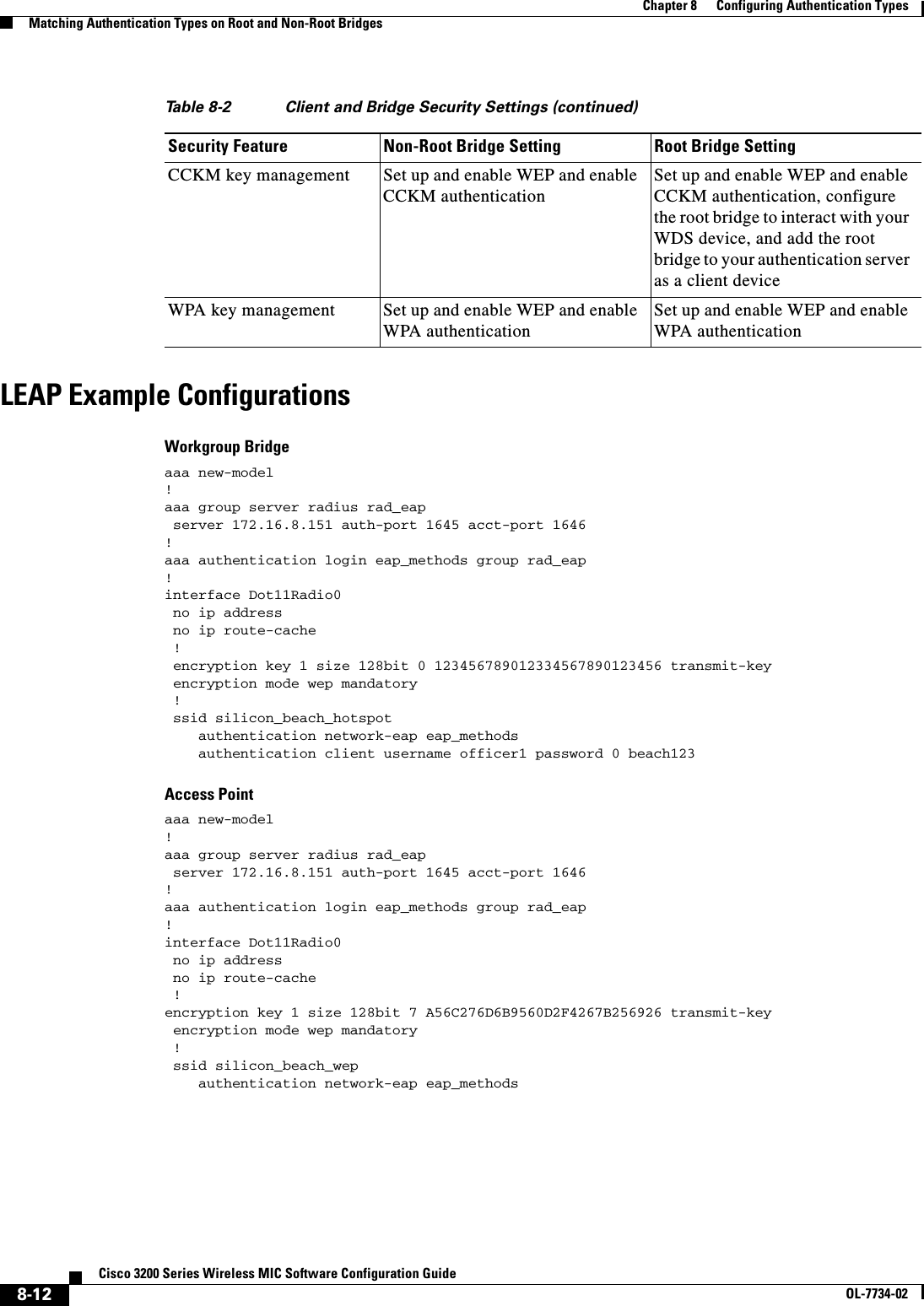
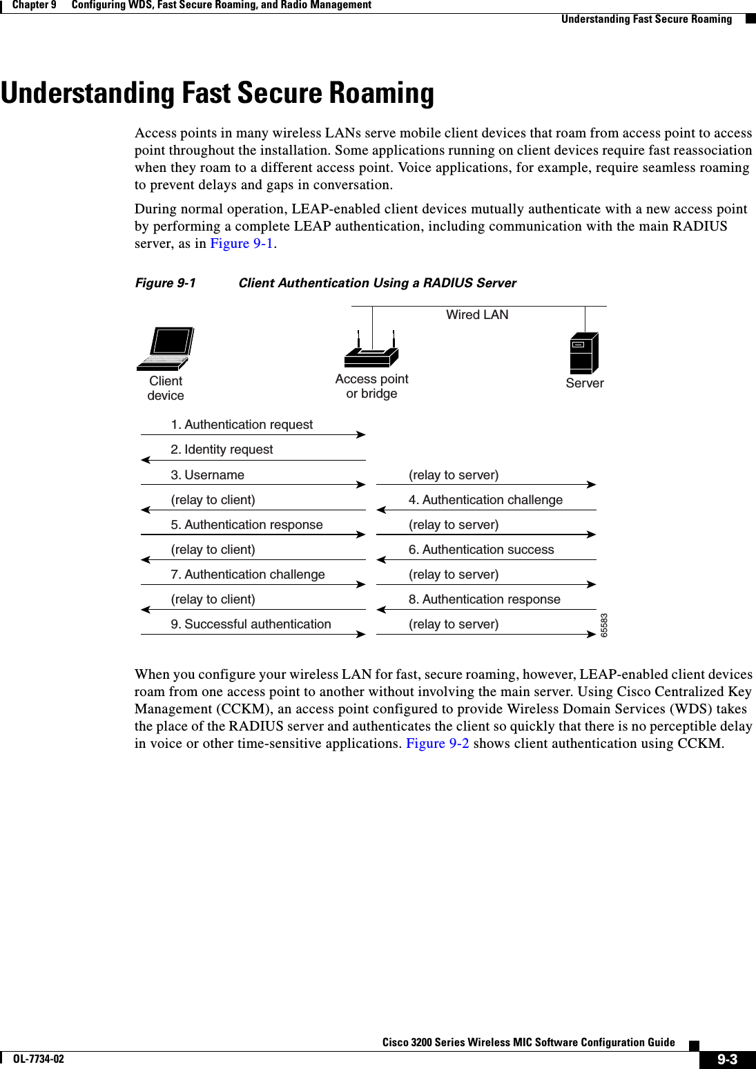
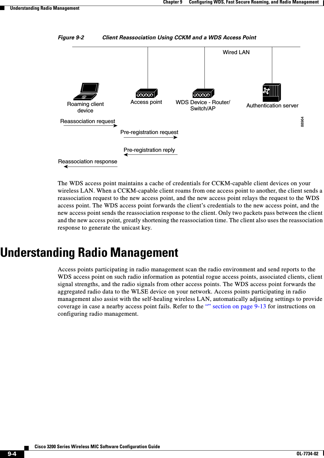
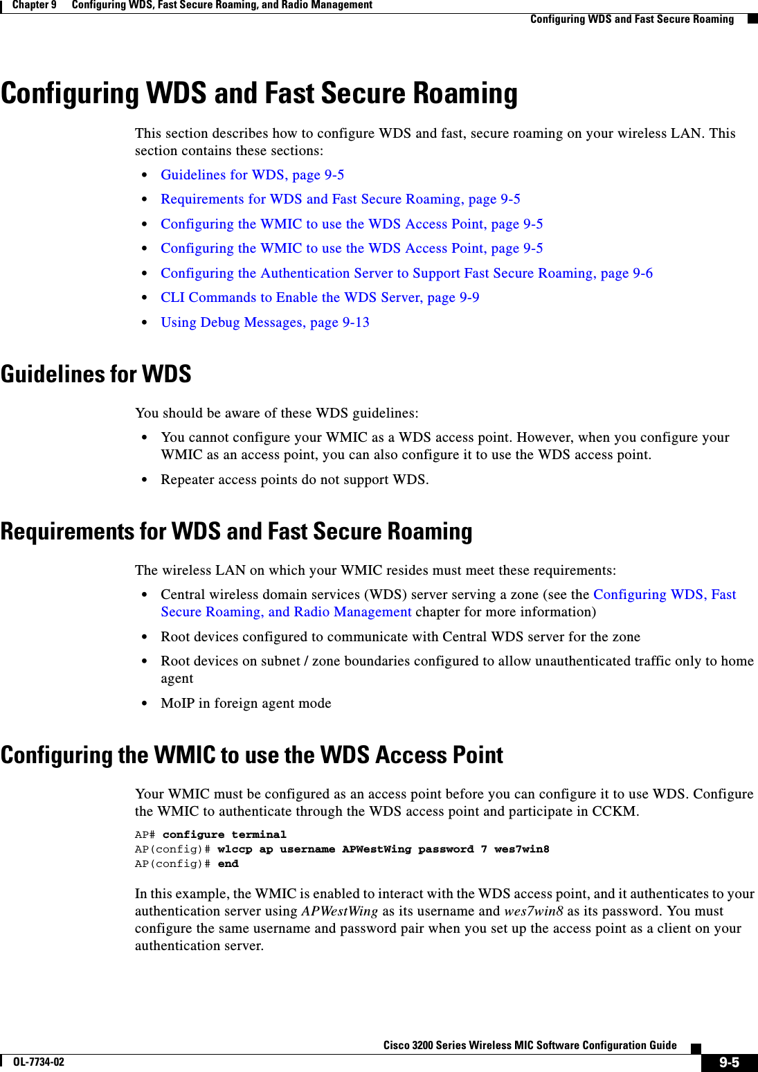
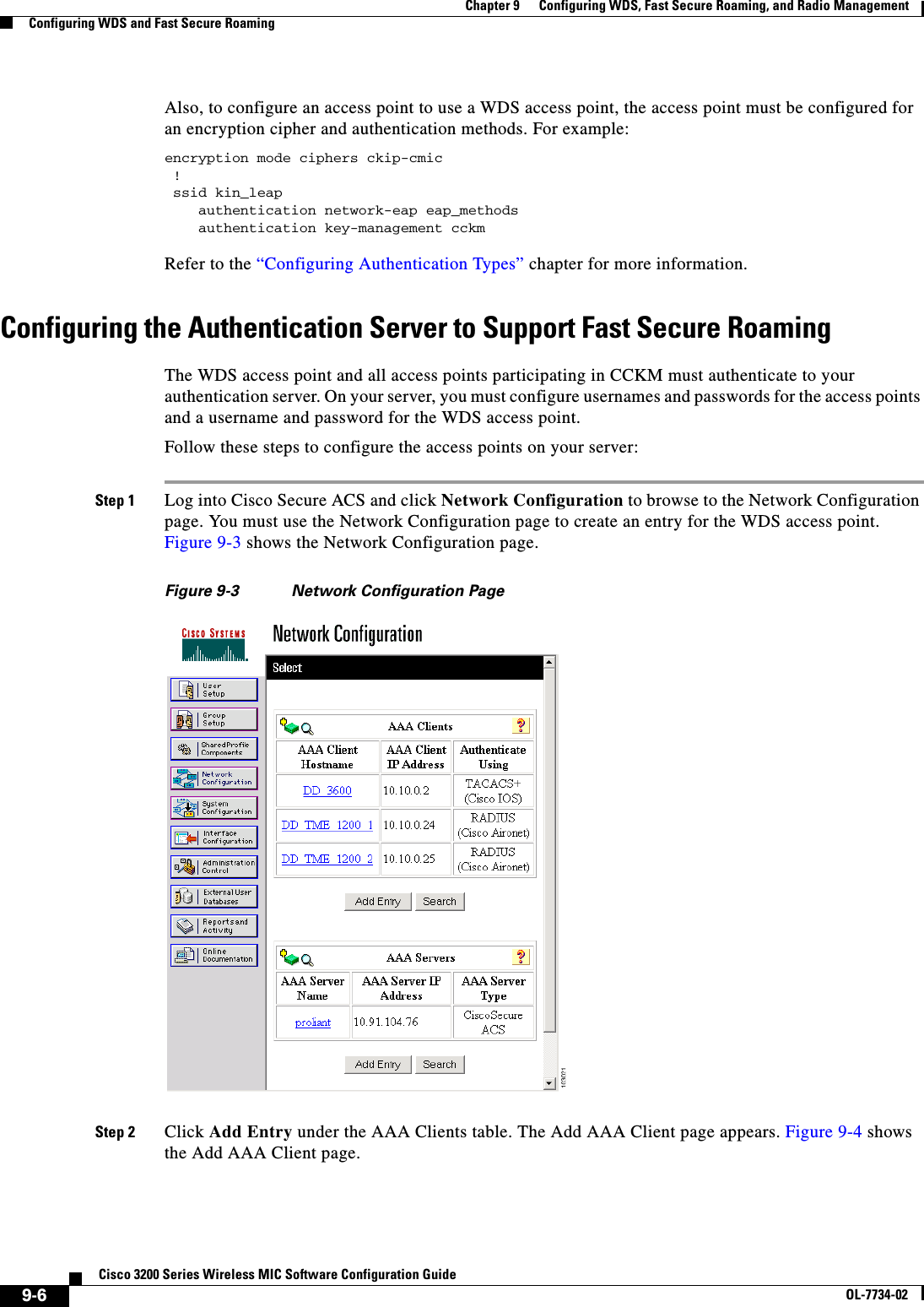
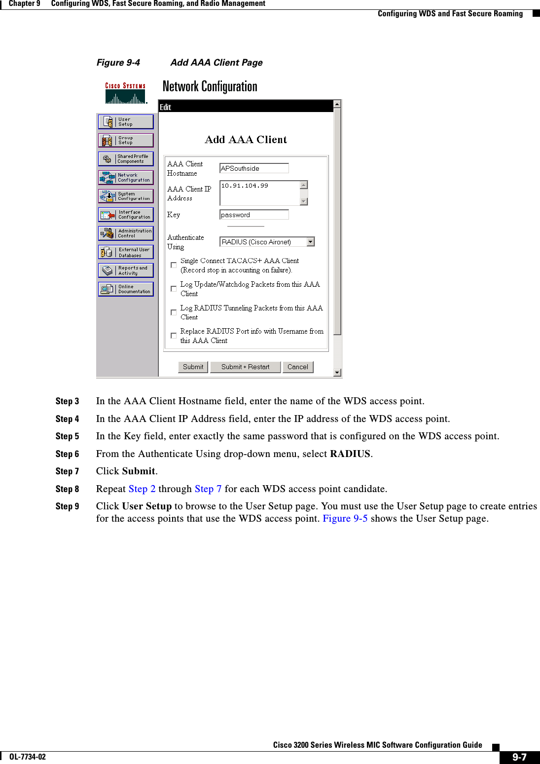
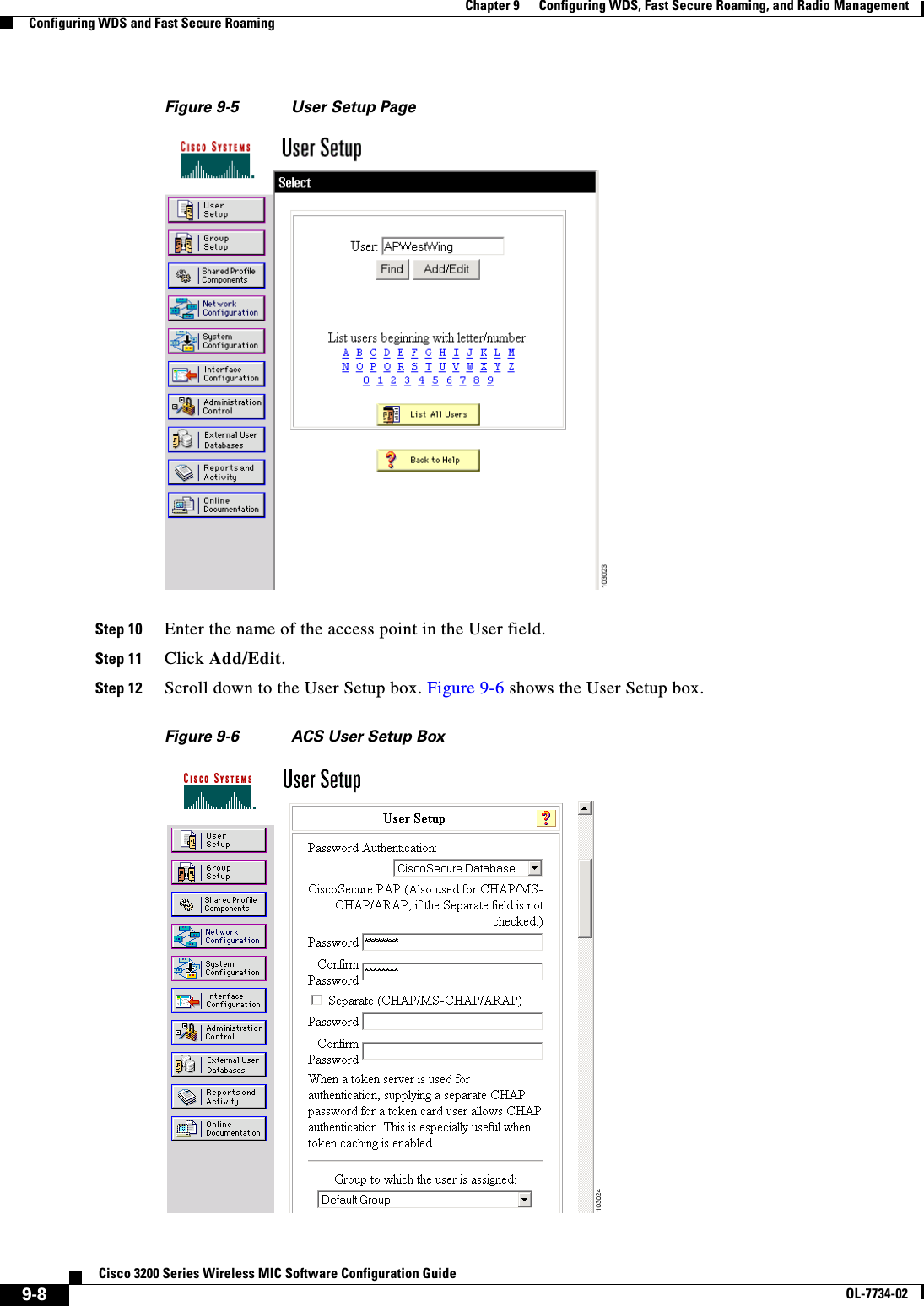
![9-9Cisco 3200 Series Wireless MIC Software Configuration GuideOL-7734-02Chapter 9 Configuring WDS, Fast Secure Roaming, and Radio ManagementConfiguring WDS and Fast Secure RoamingStep 13 Select CiscoSecure Database from the Password Authentication drop-down menu.Step 14 In the Password and Confirm Password fields, enter exactly the same password that you entered on the access point on the Wireless Services AP page.Step 15 Click Submit.Step 16 Repeat Step 10 through Step 15 for each access point that uses the WDS access point.Step 17 Browse to the System Configuration page, click Service Control, and restart ACS to apply your entries. Figure 9-7 shows the System Configuration page.Figure 9-7 ACS System Configuration PageCLI Commands to Enable the WDS ServerThe following CLI commands are required to enable the WDS server. The no form of the commands disables the WDS server. The same configuration applies for Central WDS server and per subnet WDS server.[no] wlccp wds priority <1-255> interface BVI1[no] wlccp authentication-server infrastructure <method_infra>where <method_infra> is <authentication server list name>[no] wlccp authentication-server client [any | eap | leap | mac] <method_client>where <method_ client > is <authentication server list name>[no] aaa group server radius infra[no] server <IP address of RADIUS server> auth-port <Port number> acct-port <Port number>[no] aaa group server radius client[no] server <IP address of RADIUS server> auth-port <Port number> acct-port <Port number> [no] aaa authentication login <method_infra> group infrawhere <method_infra> is <named authentication list>[no] aaa authentication login <method_client> group client](https://usermanual.wiki/Cisco-Systems/XSCLCR14/User-Guide-558354-Page-173.png)
![9-10Cisco 3200 Series Wireless MIC Software Configuration GuideOL-7734-02Chapter 9 Configuring WDS, Fast Secure Roaming, and Radio ManagementConfiguring WDS and Fast Secure Roamingwhere <method_ client > is <named authentication list>CLI Commands to Enable the Root DeviceThe following CLI commands are required to enable the root device to communicate with the Central WDS server. The no form disables the WDS server. This configuration also allows the Root device to authenticate with per subnet WDS server if the Central WDS server fails.[no] wlccp ap wds ip address <IP address of the WDS>[no] wlccp ap username <WLCCP user name> password 0 <The UNENCRYPTED (cleartext) LEAP password>[no] interface Dot11Radio0[no] encryption mode ciphers [aes-ccm | tkip | wep128 | wep40][no] ssid <radio Service Set ID>[no] authentication network-eap <eap_methods>where <eap_methods> is <leap list name> [no] authentication key-management cckm[no] aaa group server radius rad_eap[no] server <IP address of RADIUS server> auth-port <Port number> acct-port <Port number>[no] aaa authentication login <eap_methods> group rad_eapwhere <eap_methods> is <named authentication list>The authentication network-eap <eap_methods> command allows traffic to and from the client while it is being authenticated by the root device. This command should be entered on all the root devices located in zone boundaries and on all the clients.authentication network-eap <eap_methods> <non-blocking>where <non-blocking> allows a client to send or receive traffic while the root device is authenticating the client.To enable blocking of client traffic during authentication, enter the command without the non-blockingkeyword.authentication network-eap <eap_methods>Refer to http://www.cisco.com/univercd/cc/td/doc/product/software/ios123/123cgcr/ibm_r1/ib1_a1g.pdf for details on configuring access control lists on an access point to allow clients to send traffic to a home agent only.Refer to http://www.cisco.com/univercd/cc/td/doc/product/software/ios123/123cgcr/iprmb_r/ip4bookg.pdf for details on Mobile IP configuration commands.Refer to http://www.cisco.com/univercd/cc/td/doc/product/software/ios123/123newft/123t/123t_7/gtfamoip.htmfor details on the foreign agent local routing feature and its configuration details.](https://usermanual.wiki/Cisco-Systems/XSCLCR14/User-Guide-558354-Page-174.png)
![9-11Cisco 3200 Series Wireless MIC Software Configuration GuideOL-7734-02Chapter 9 Configuring WDS, Fast Secure Roaming, and Radio ManagementConfiguring WDS and Fast Secure Roamingdot11 interface speed CommandThe dot11 interface speed command supports only 4.9-GHz data rates. The configured spacing has precedence over the default spacing. For example, if 5-MHz spacing is configured, only data rates corresponding to 5-MHz spacing can be specified in the speed command. If an incorrect data rate is specified for the currently configured spacing, an error message displays, “Incorrect data rate for currently configured spacing.”[no] interface Dot11Radio0[no] speed <data rate>where data rate can be one of the following:Data Rate Description Spacing1.5 Allow 1.5 Mbps 5-MHz2.25 Allow 2.25 Mbps 5-MHz 3.0 Allow 3.0 Mbps 5-MHz and 10-MHz 4.5 Allow 4.5 Mbps 5-MHz and 10-MHz 6.0 Allow 6.0 Mbps 5-MHz and 10-MHz 9.0 Allow 9.0 Mbps 5-MHz and 10-MHz 12.0 Allow 12.0 Mbps 5-MHz and 10-MHz 13.5 Allow 13.5 Mbps 5-MHz18.0 Allow 18.0 Mbps 10-MHz24.0 Allow 24.0 Mbps 10-MHz27.0 Allow 27.0 Mbps 10-MHzbasic-1.5 Require 1.5 Mbps 5-MHzbasic-2.25 Require 2.25 Mbps 5-MHzbasic-3.0 Require 3 Mbps 5-MHz and 10-MHz basic-4.5 Require 4.5 Mbps 5-MHz and 10-MHz basic-6.0 Require 6 Mbps 5-MHz and 10-MHz basic-9.0 Require 9 Mbps 5-MHz and 10-MHz basic-12.0 Require 12 Mbps 5-MHz and 10-MHz basic-13.5 Require 13.5 Mbps 5-MHz basic-18.0 Require 18 Mbps 10-MHz basic-24.0 Require 24 Mbps 10-MHz basic-27.0 Require 27 Mbps 10-MHz default Set default rates Table 9-1 shows the default rates.range Set rates for best range Table 9-1 shows the best range.throughput Set rates for best throughput Table 9-1 shows the best throughput rates.Table 9-1 Default Rates, Best Range Rates and Best Throughput Rates5-MHz Spacing 10-MHz SpacingDefault Rates: basic-1.5, 2.25, basic-3.0, 4.5, basic-6.0, 9.0, 12.0, 13.5Default Rates: basic-3.0, 4.5, basic-6.0, 9.0, basic-12.0, 18.0, 24.0, 27.0](https://usermanual.wiki/Cisco-Systems/XSCLCR14/User-Guide-558354-Page-175.png)
![9-12Cisco 3200 Series Wireless MIC Software Configuration GuideOL-7734-02Chapter 9 Configuring WDS, Fast Secure Roaming, and Radio ManagementConfiguring WDS and Fast Secure RoamingViewing WDS InformationOn the web-browser interface, browse to the Wireless Services Summary page to view a summary of WDS status.On the CLI in privileged exec mode, use these commands to view information about the current WDS access point and other access points participating in CCKM:Rates for Best Range: basic-1.5, 2.25, 3.0, 4.5, 6.0, 9.0, 12.0, 13.5 Rates for Best Range: basic-3.0, 4.5, 6.0 9.0 12.0 18.0 24.0 27.0 Rates for Best Throughput: basic-1.5, basic-2.25, basic-3.0, basic-4.5, basic-6.0, basic-9.0, basic- 12.0, basic-13.5Rates for Best Throughput: basic-3.0, basic-4.5, basic-6.0, basic-9.0, basic-12.0, basic-18.0, basic-24.0, basic-27.0Table 9-1 Default Rates, Best Range Rates and Best Throughput RatesCommand Descriptionshow wlccp ap Use this command on access points participating in CCKM to display the WDS access point’s MAC address, the WDS access point’s IP address, the access point’s state (authenticating, authenticated, or registered), the IP address of the infrastructure authenticator, and the IP address of the client device (MN) authenticator.show wlccp wds { ap | mn }[detail ] [ mac-addr mac-address ]On the WDS access point only, use this command to display cached information about access points and client devices.•ap—Use this option to display access points participating in CCKM. The command displays each access point’s MAC address, IP address, state (authenticating, authenticated, or registered), and lifetime (seconds remaining before the access point must reauthenticate). Use the mac-addr option to display information about a specific access point.•mn—Use this option to display cached information about client devices, also called mobile nodes. The command displays each client’s MAC address, IP address, the access point to which the client is associated (cur-AP), and state (authenticating, authenticated, or registered). Use the detailoption to display the client’s lifetime (seconds remaining before the client must reauthenticate), SSID, and VLAN ID. Use the mac-addr option to display information about a specific client device.If you only enter show wlccp wds, the command displays the access point’s IP address, MAC address, priority, and interface state (administratively standalone, active, backup, or candidate). If the state is backup, the command also displays the current WDS access point’s IP address, MAC address, and priority.](https://usermanual.wiki/Cisco-Systems/XSCLCR14/User-Guide-558354-Page-176.png)
![9-13Cisco 3200 Series Wireless MIC Software Configuration GuideOL-7734-02Chapter 9 Configuring WDS, Fast Secure Roaming, and Radio ManagementConfiguring WDS and Fast Secure RoamingUsing Debug MessagesIn privileged exec mode, use these debug commands to control the display of debug messages for devices interacting with the WDS access point:Command Descriptiondebug wlccp ap{ mn | mobility | rm | state |wds-discovery }Use this command to turn on display of debug messages related to client devices (mn), the WDS discovery process, and access point authentication to the WDS access point (state).debug wlccp leap-client Use this command to turn on display of debugging messages related to LEAP-enabled client devices.debug wlccp packet Use this command to turn on display of packets to and from the WDS access point.debug wlccp wds [state | statistics ]Use this command and the state option to turn on display of WDS debug and state messages. Use the statistics option to turn on display of failure statistics.](https://usermanual.wiki/Cisco-Systems/XSCLCR14/User-Guide-558354-Page-177.png)

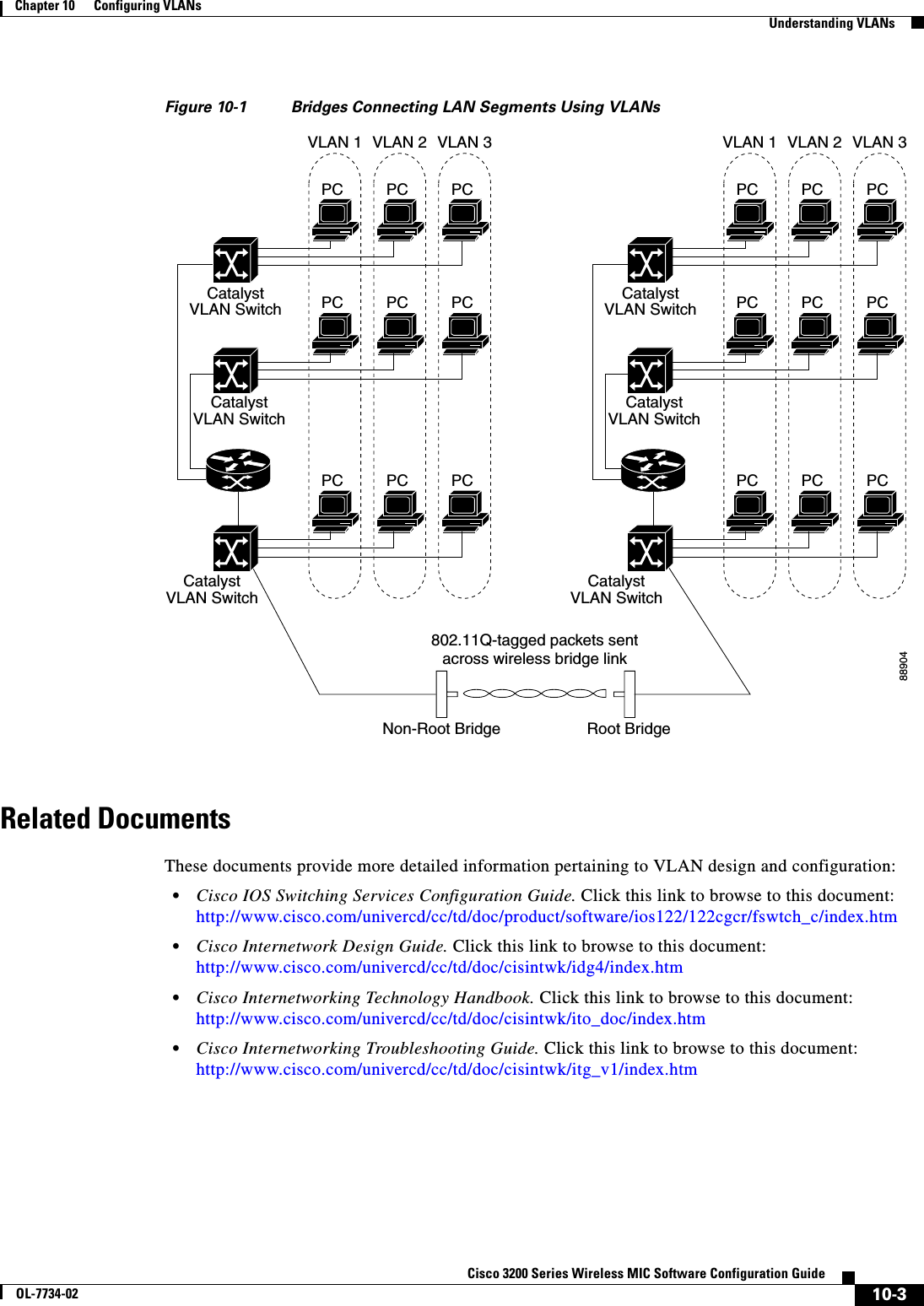
![10-4Cisco 3200 Series Wireless MIC Software Configuration GuideOL-7734-02Chapter 10 Configuring VLANsConfiguring VLANsIncorporating Wireless Bridges into VLANsThe basic wireless components of a VLAN consist of two or more bridges communicating using wireless technology. The WMIC is physically connected through a trunk port to the network VLAN switch on which the VLAN is configured. The physical connection to the VLAN switch is through the WMIC’s Ethernet port.In fundamental terms, the key to configuring a WMIC to connect to a specific VLAN is by configuring its SSID to recognize that VLAN. Since VLANs are identified by a VLAN ID, it follows that if the SSID on a WMIC is configured to recognize a specific VLAN ID, a connection to the VLAN is established. The WMIC supports 16 SSIDs. You can assign only one SSID to the native VLAN.Configuring VLANsThese sections describe how to configure VLANs on your WMIC:•Configuring a VLAN, page 10-4•Viewing VLANs Configured on the WMIC, page 10-7Configuring a VLANConfiguring your WMIC to support VLANs is a five-step process:1. Create subinterfaces on the radio and Ethernet interfaces.2. Enable 802.1q encapsulation on the subinterfaces and assign one subinterface as the native VLAN.3. Assign a bridge group to each VLAN.4. (Optional) Enable WEP on the native VLAN.5. Assign the WMIC’s SSID to the native VLAN.This section describes how to assign an SSID to a VLAN and how to enable a VLAN on the WMIC radio and Ethernet ports. For detailed instructions on assigning authentication types to SSIDs, see Chapter 8, “Configuring Authentication Types.”Beginning in privileged EXEC mode, follow these steps to assign an SSID to a VLAN and enable the VLAN on the WMIC radio and Ethernet ports:Command PurposeStep 1 configure terminal Enter global configuration mode.Step 2 interface dot11radio0.x Create a radio subinterface and enter interface configuration mode for the subinterface.Step 3 encapsulation dot1q vlan-id[native]Enable a VLAN on the subinterface. (Optional) Designate the VLAN as the native VLAN. On many networks, the native VLAN is VLAN 1.](https://usermanual.wiki/Cisco-Systems/XSCLCR14/User-Guide-558354-Page-182.png)
![10-5Cisco 3200 Series Wireless MIC Software Configuration GuideOL-7734-02Chapter 10 Configuring VLANsConfiguring VLANsStep 4 bridge-group number Assign the subinterface to a bridge group. You can number your bridge groups from 1 to 255.Note When you enter the bridge-group command, the WMIC enables the subinterface to be ready to participate in STP when you enter the bridge nprotocol ieee command. See Chapter 6, “Configuring Spanning Tree Protocol,” for complete instructions on enabling STP on the WMIC.Step 5 exit Return to global configuration mode.Step 6 interface fastEthernet0.x Create an Ethernet subinterface and enter interface configuration mode for the subinterface.Step 7 encapsulation dot1q vlan-id[native]Enable a VLAN on the subinterface. (Optional) Designate the VLAN as the native VLAN. On many networks, the native VLAN is VLAN 1.Step 8 bridge-group number Assign the subinterface to a bridge group. You can number your bridge groups from 1 to 255.Step 9 exit Return to global configuration mode.Step 10 interface dot11radio 0 Enter interface configuration mode for the radio interface.Step 11 ssid ssid-string Create an SSID and enter SSID configuration mode for the new SSID. The SSID can consist of up to 32 alphanumeric characters. SSIDs are case sensitive. You can create up to 16 SSIDs on the bridge; however, only one SSID can be assigned to the native VLAN.Note You use the ssid command’s authentication options to configure an authentication type for each SSID. See Chapter 8, “Configuring Authentication Types,” for instructions on configuring authentication types.Step 12 vlan vlan-id Assign the SSID to the native VLAN.Step 13 infrastructure-ssid Designate the SSID as the infrastructure SSID. It is used to instruct a non-root bridge or workgroup bridge radio to associate with this SSID.Command Purpose](https://usermanual.wiki/Cisco-Systems/XSCLCR14/User-Guide-558354-Page-183.png)
![10-6Cisco 3200 Series Wireless MIC Software Configuration GuideOL-7734-02Chapter 10 Configuring VLANsConfiguring VLANsThis example shows how to:•Enable the VLAN on the radio and Ethernet ports as the native VLAN•Name an SSID•Assign the SSID to a VLANbridge# configure terminalbridge(config)# interface dot11radio0.1bridge(config-subif)# encapsulation dot1q 1 nativebridge(config-subif)# bridge group 1bridge(config-subif)# exitbridge(config)# interface fastEthernet0.1bridge(config-subif)# encapsulation dot1q 1 nativebridge(config-subif)# bridge group 1bridge(config-subif)# exitbridge(config)# interface dot11radio0bridge(config-if)# ssid batmanbridge(config-ssid)# vlan 1bridge(config-ssid)# infrastructure-ssidbridge(config-ssid)# endStep 14 encryption[vlan vlan-id]mode wep {optional [key-hash] | mandatory [mic] [key-hash]}(Optional) Enable WEP and WEP features on the native VLAN.•(Optional) Select the VLAN for which you want to enable WEP and WEP features.•Set the WEP level and enable TKIP and MIC. If you enter optional, another bridge can associate to the WMIC with or without WEP enabled. You can enable TKIP with WEP set to optional but you cannot enable MIC. If you enter mandatory, other bridges must have WEP enabled to associate to the WMIC. You can enable both TKIP and MIC with WEP set to mandatory.Note You can enable encryption for each VLAN, but the WMIC uses only the encryption on the native VLAN. For example, if the native VLAN encryption is set to 128-bit static WEP, that is the only encryption method used for traffic between the root and non-root bridge.Step 15 exit Return to interface configuration mode for the radio interface.Step 16 end Return to privileged EXEC mode.Step 17 copy running-config startup-config (Optional) Save your entries in the configuration file.Command Purpose](https://usermanual.wiki/Cisco-Systems/XSCLCR14/User-Guide-558354-Page-184.png)
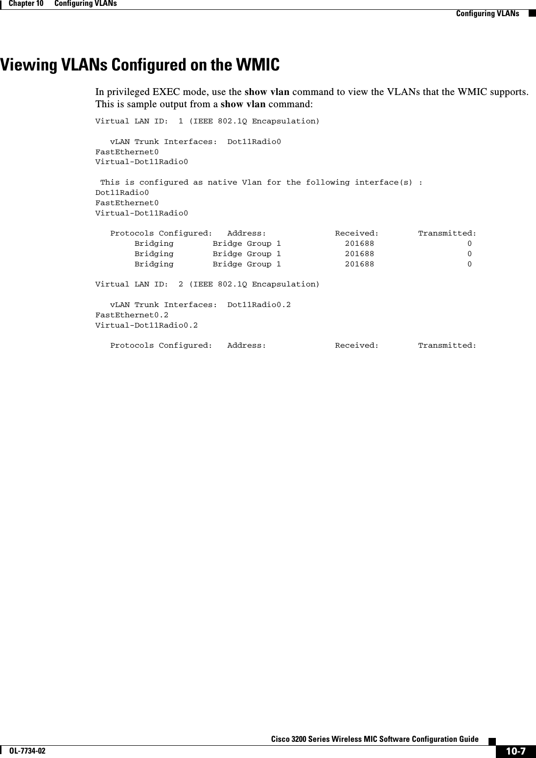

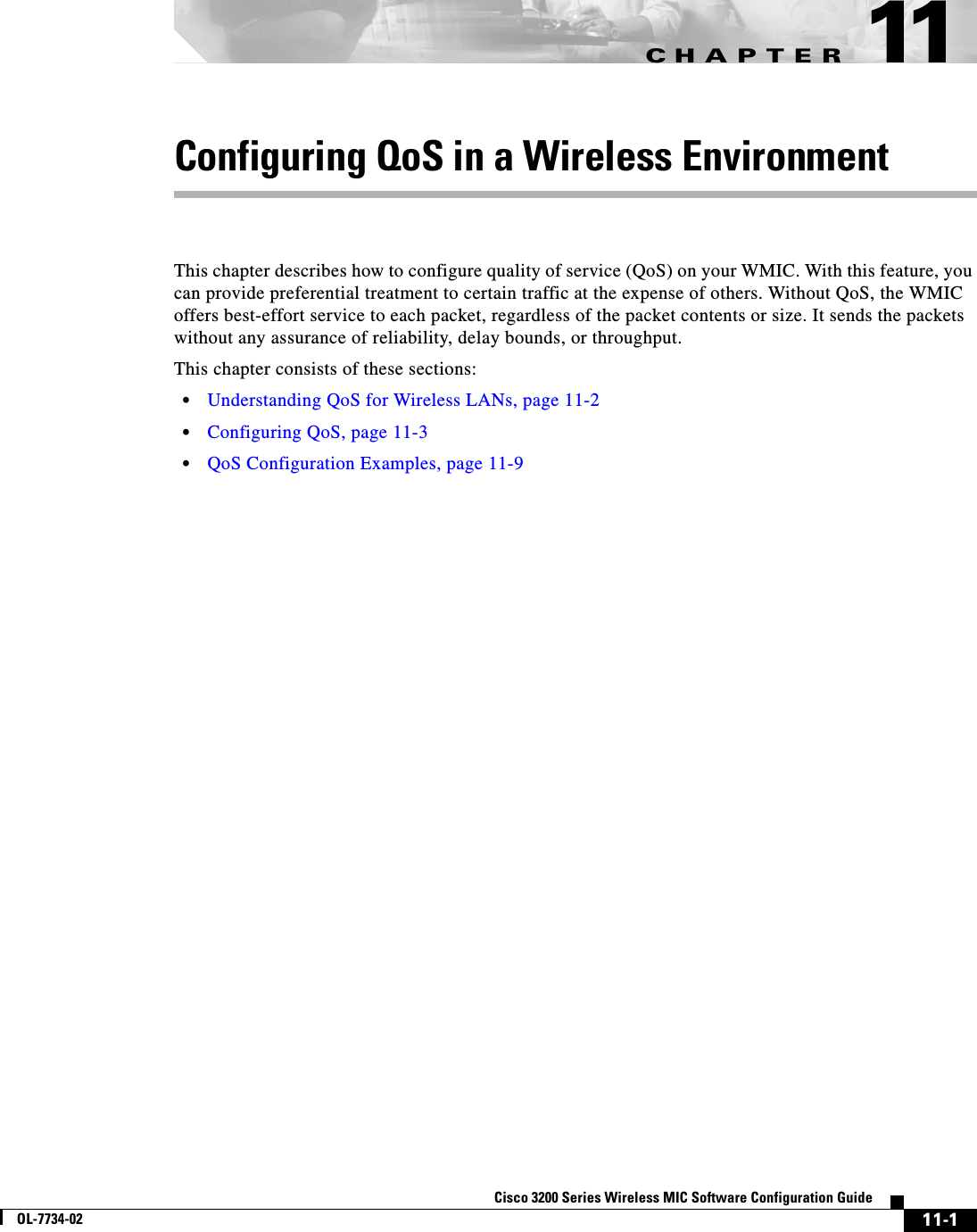
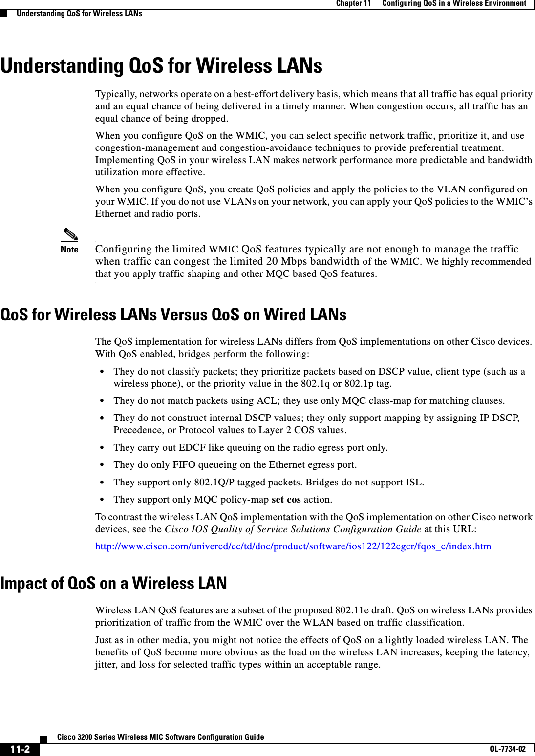
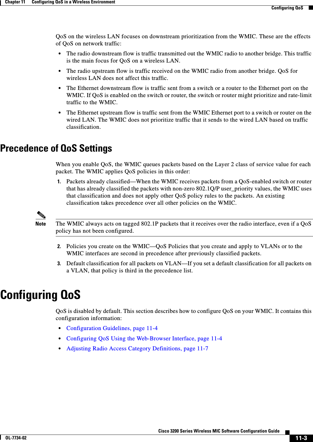
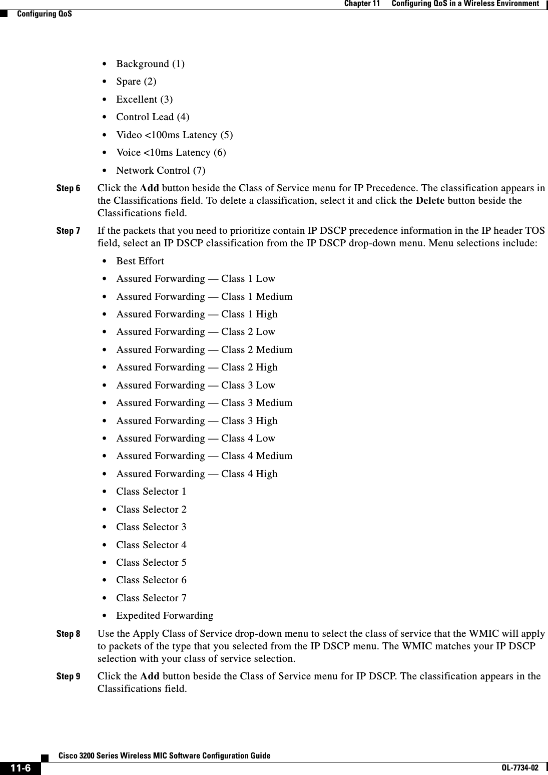
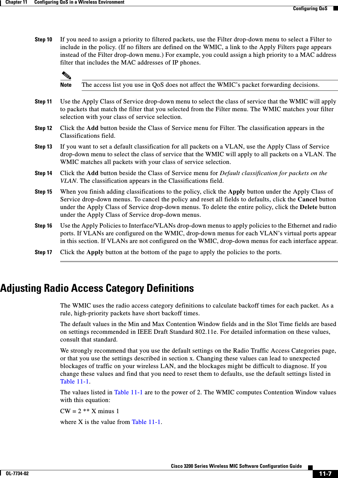
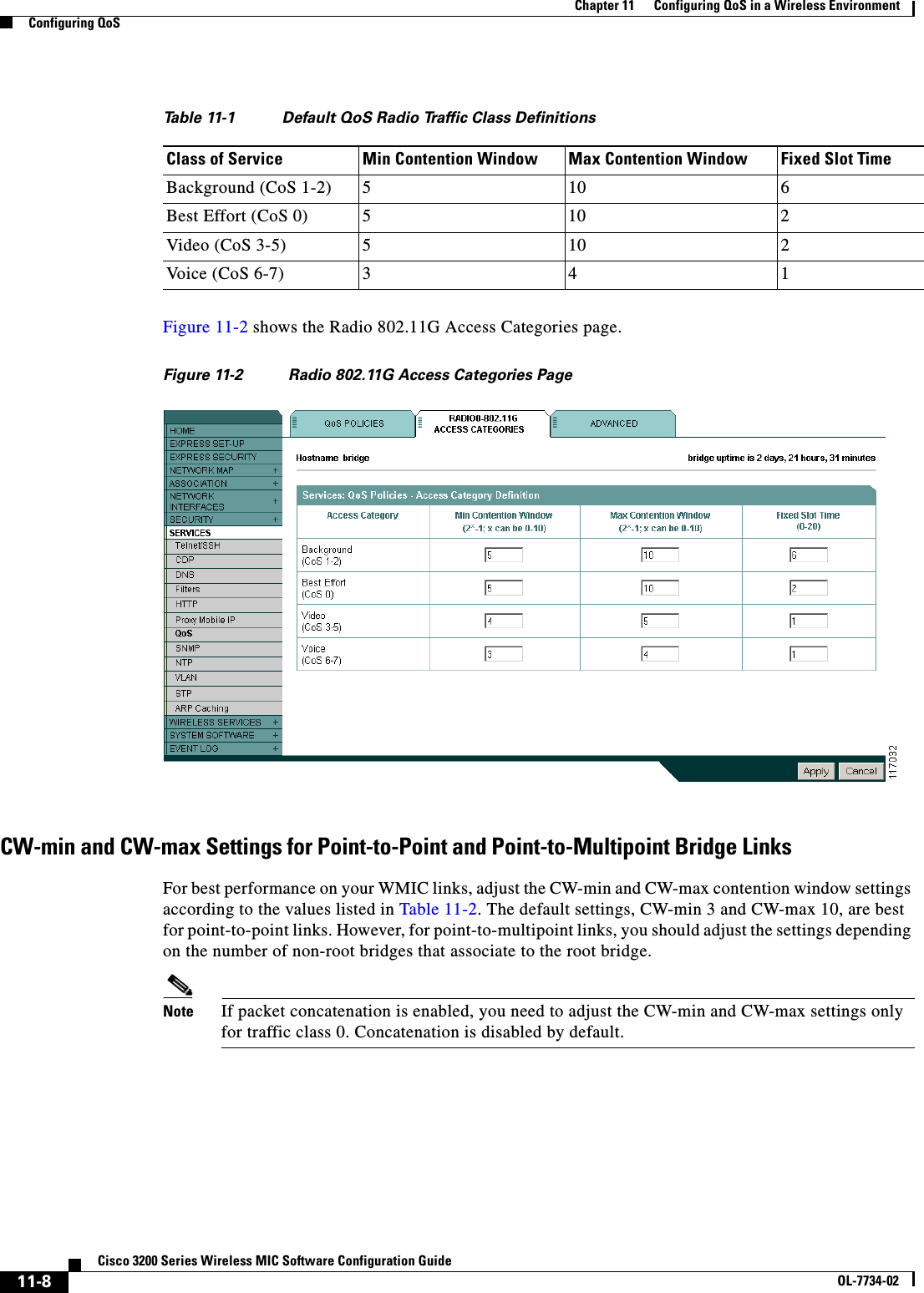
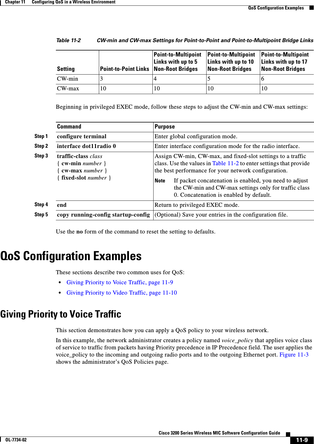
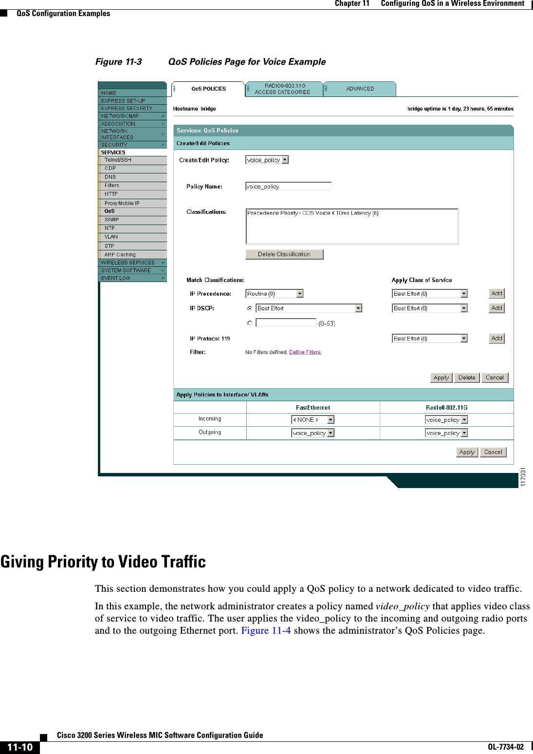
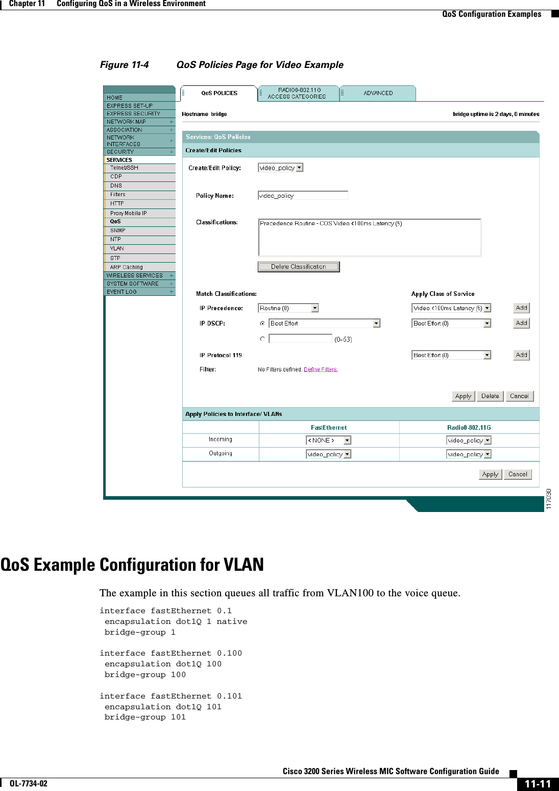


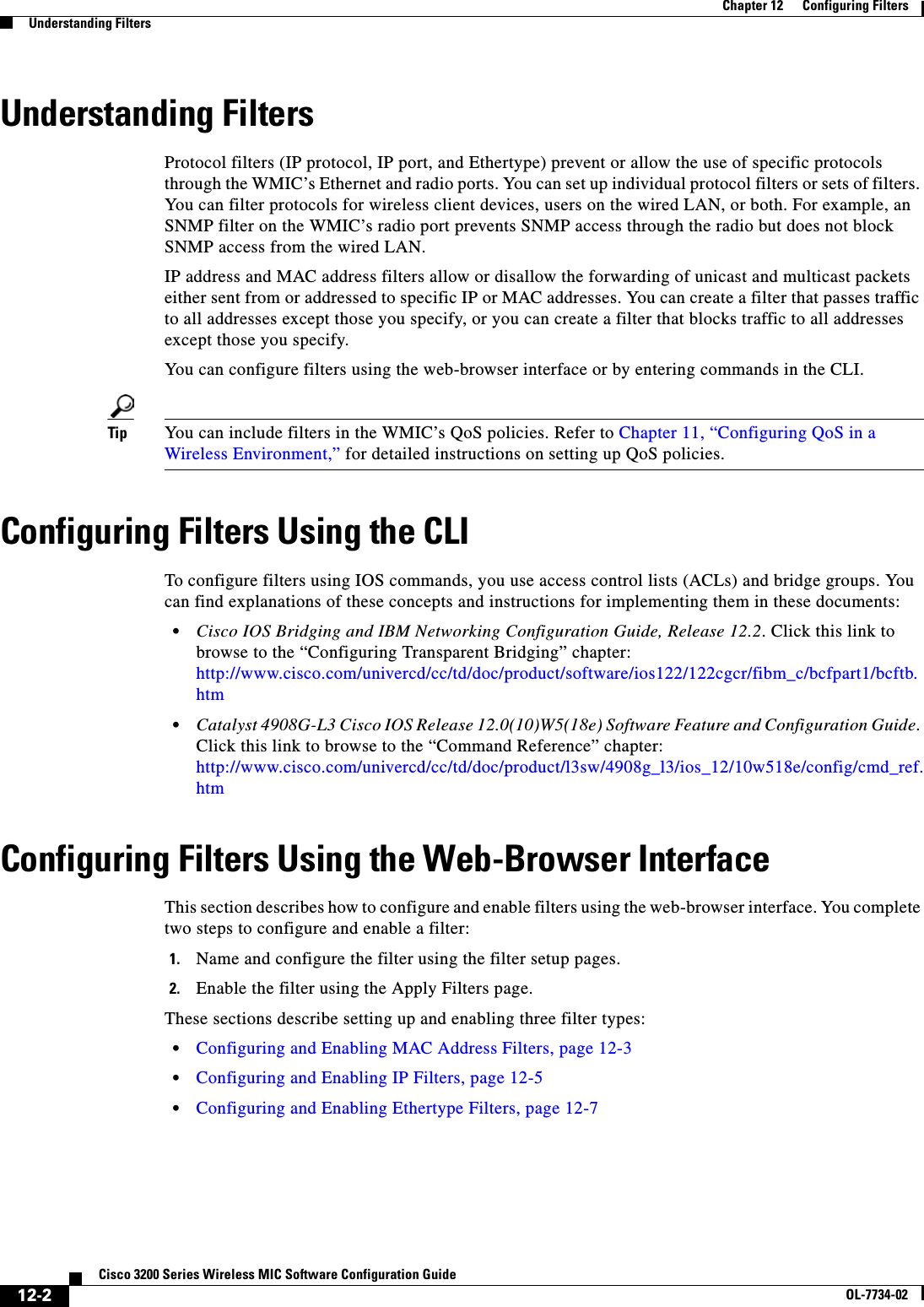
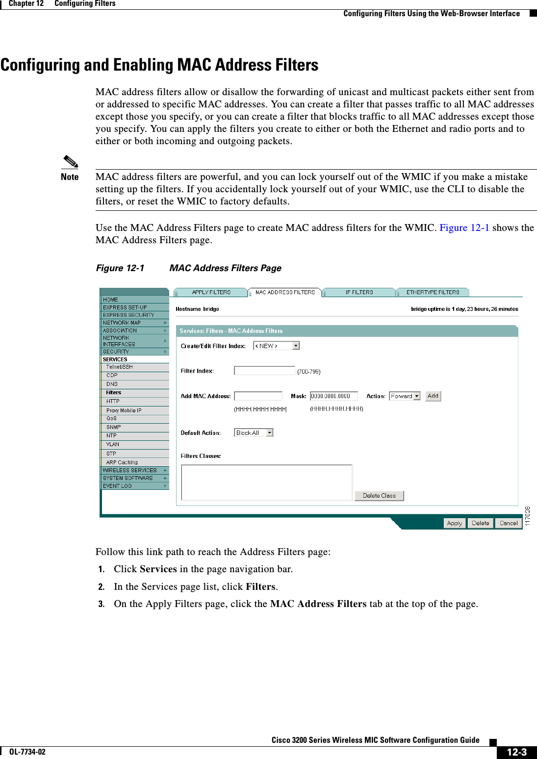
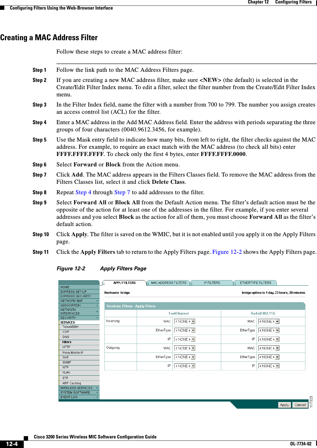
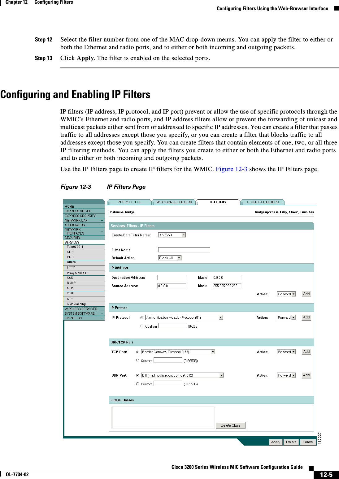
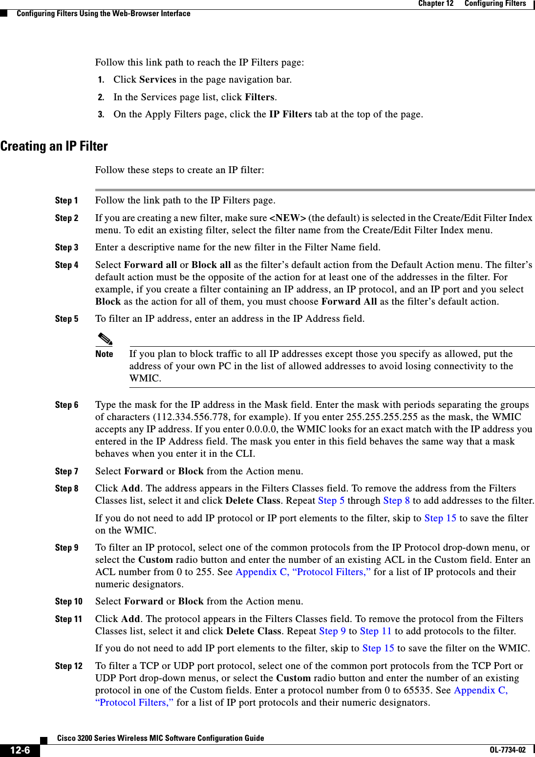
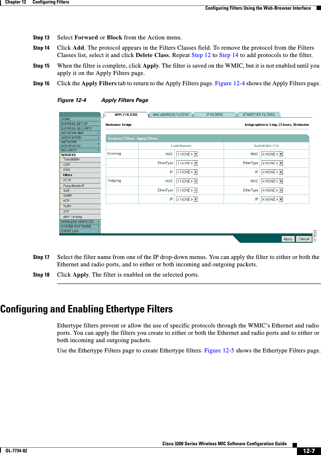
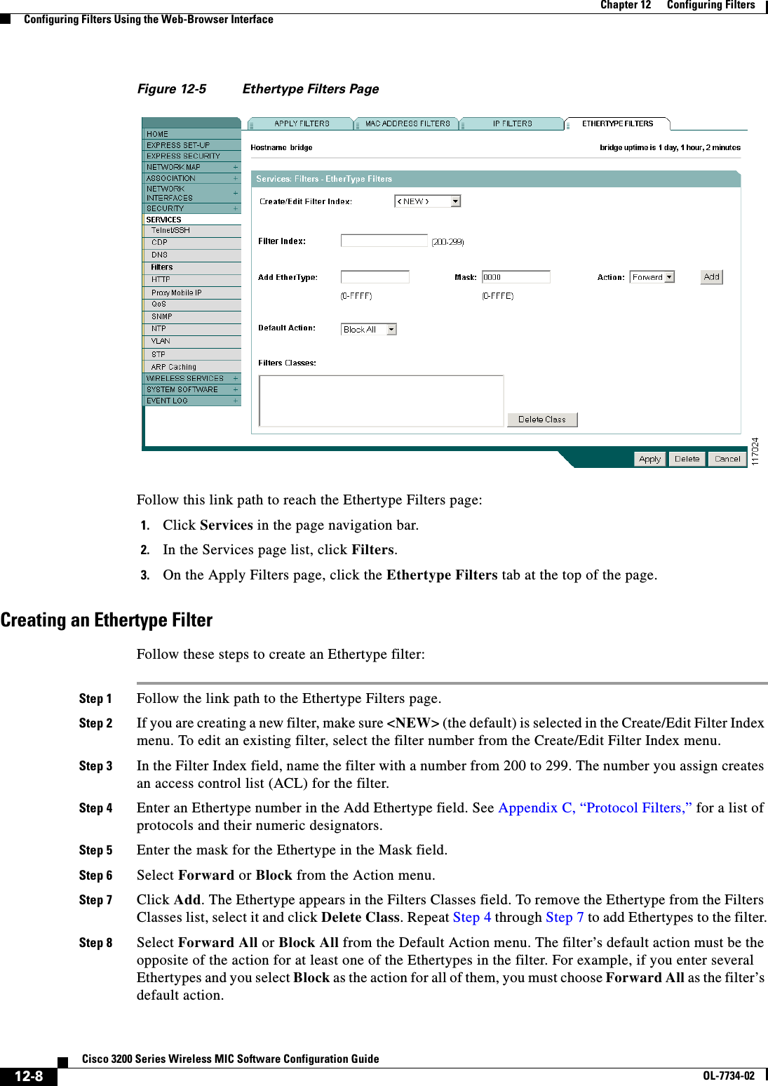
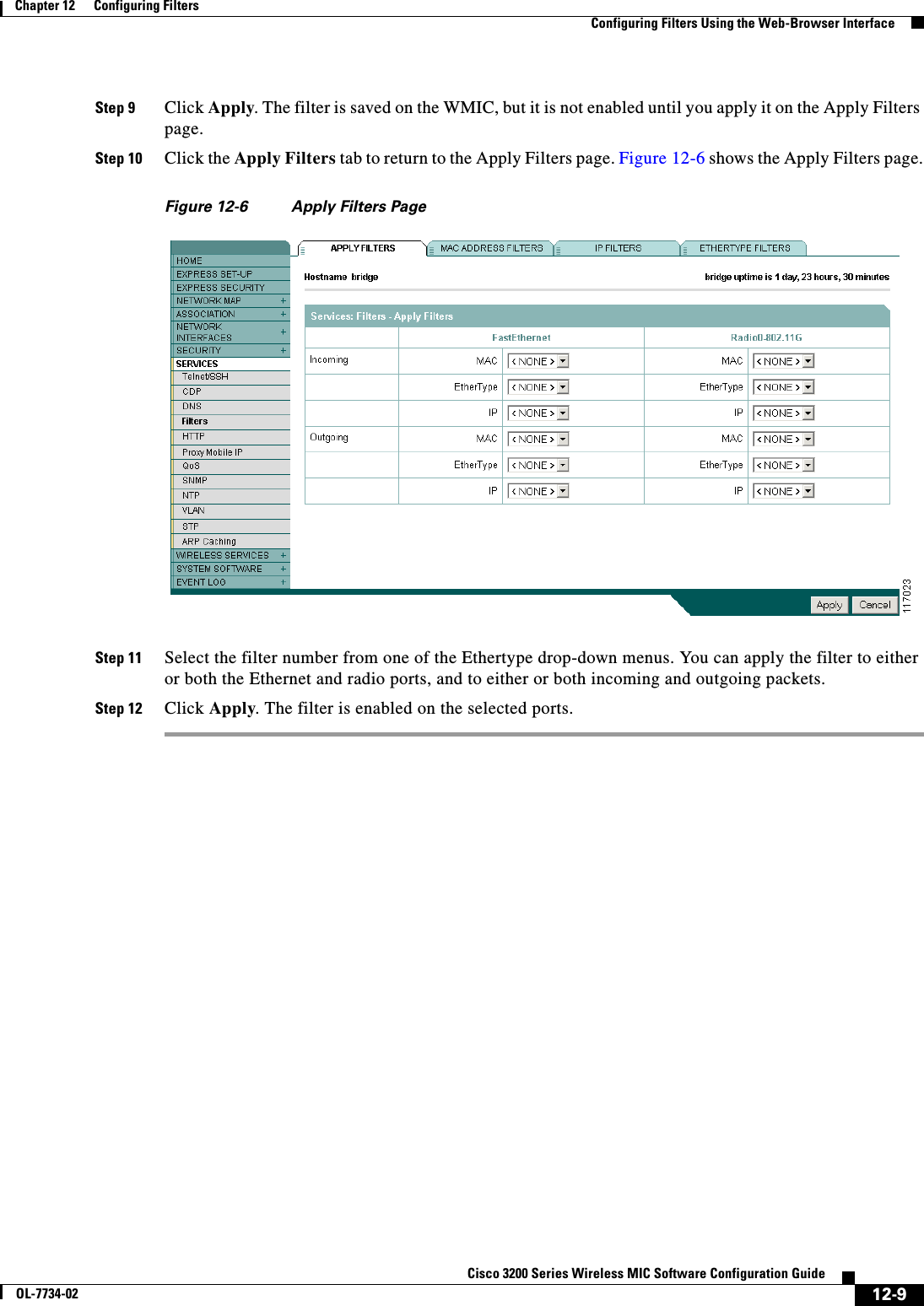

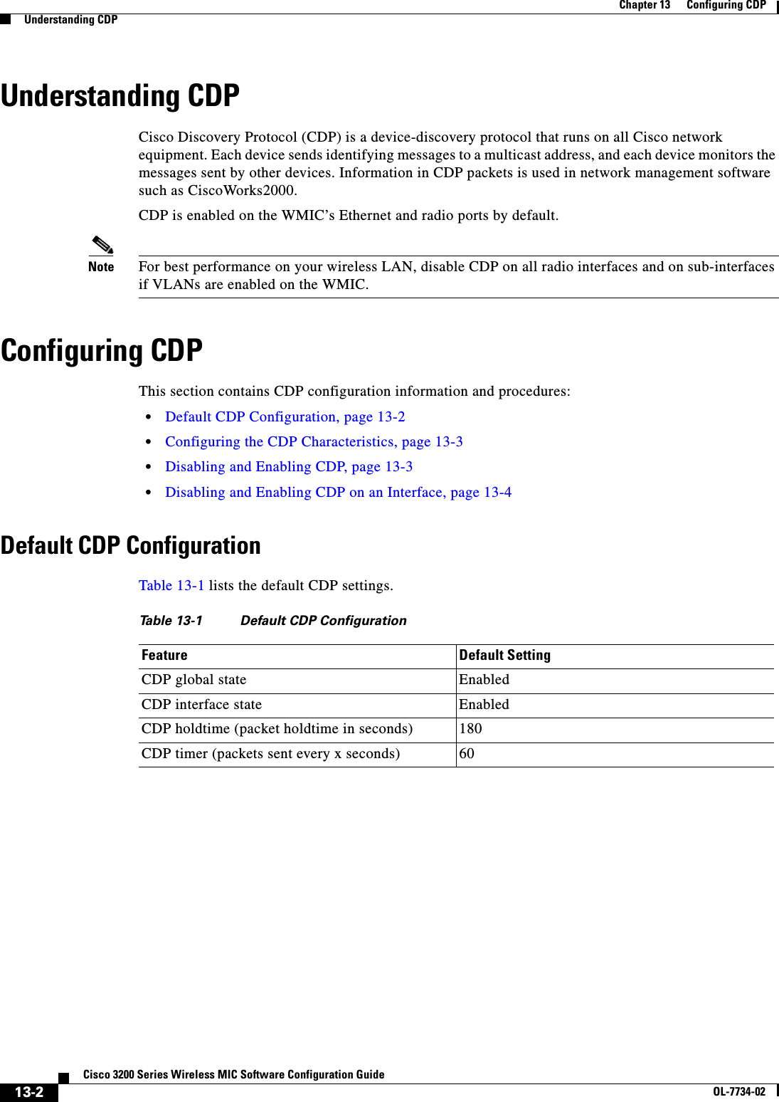
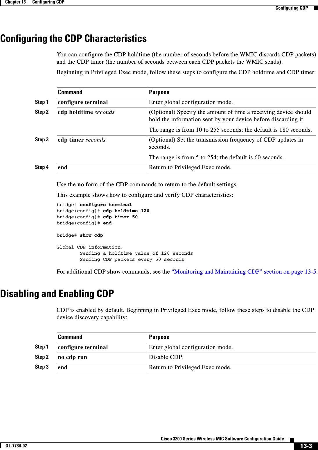
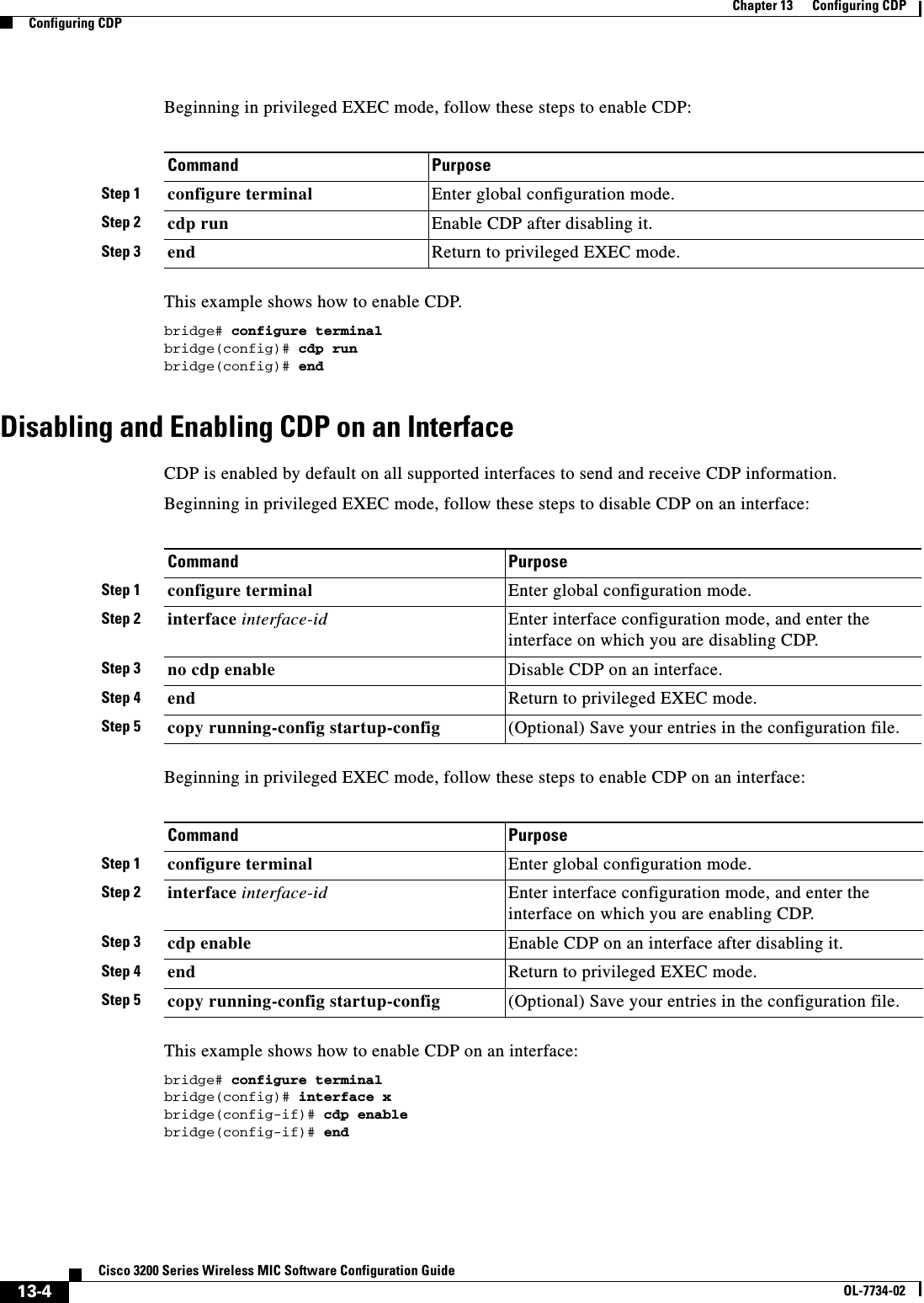
![13-5Cisco 3200 Series Wireless MIC Software Configuration GuideOL-7734-02Chapter 13 Configuring CDPMonitoring and Maintaining CDPMonitoring and Maintaining CDPTo monitor and maintain CDP on your device, perform one or more of these tasks, beginning in privileged EXEC mode.Below are six examples of output from the CDP show privileged EXEC commands:bridge# show cdpGlobal CDP information: Sending CDP packets every 50 seconds Sending a holdtime value of 120 secondsbridge# show cdp entry *-------------------------Device ID: bridgeEntry address(es): IP address: 10.1.1.66Platform: cisco WS-C3550-12T, Capabilities: Switch IGMPInterface: GigabitEthernet0/2, Port ID (outgoing port): GigabitEthernet0/2Holdtime : 129 secVersion :Cisco Internetwork Operating System SoftwareIOS (tm) C3550 Software (C3550-I5Q3L2-M), Experimental Version 12.1(20010612:021316) [jang-flamingo 120]Copyright (c) 1986-2001 by cisco Systems, Inc.Compiled Fri 06-Jul-01 18:18 by jangadvertisement version: 2Command Descriptionclear cdp counters Reset the traffic counters to zero.clear cdp table Delete the CDP table of information about neighbors.show cdp Display global information, such as frequency of transmissions and the holdtime for packets being sent.show cdp entry entry-name [protocol |version]Display information about a specific neighbor. You can enter an asterisk (*) to display all CDP neighbors, or you can enter the name of the neighbor about which you want information.You can also limit the display to information about the protocols enabled on the specified neighbor or information about the version of software running on the device.show cdp interface [type number] Display information about interfaces where CDP is enabled.You can limit the display to the type of interface or the number of the interface about which you want information (for example, entering gigabitethernet 0/1 displays information only about Gigabit Ethernet port 1).show cdp neighbors [type number][detail]Display information about neighbors, including device type, interface type and number, holdtime settings, capabilities, platform, and port ID. You can limit the display to neighbors on a specific type or number of interface or expand the display to provide more detailed information.show cdp traffic Display CDP counters, including the number of packets sent and received and checksum errors.](https://usermanual.wiki/Cisco-Systems/XSCLCR14/User-Guide-558354-Page-215.png)
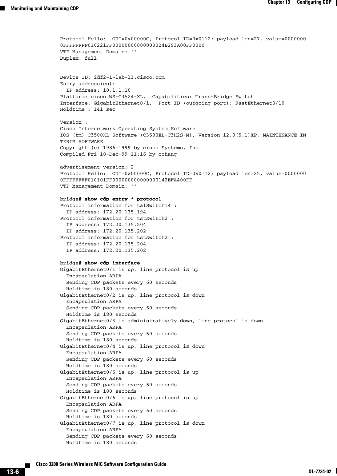
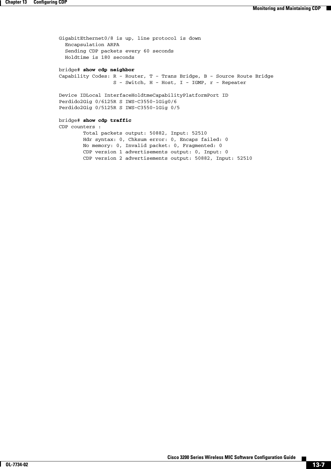

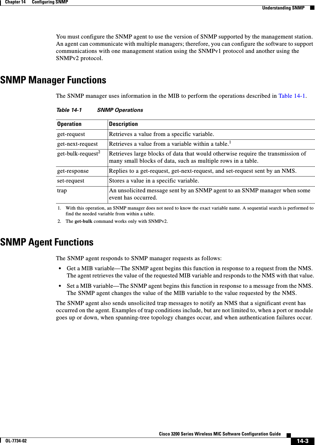
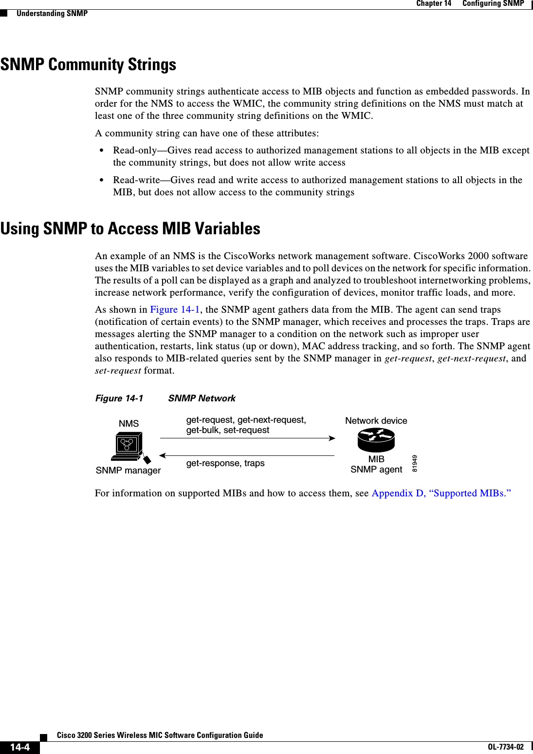
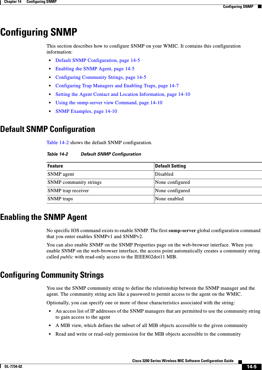
![14-6Cisco 3200 Series Wireless MIC Software Configuration GuideOL-7734-02Chapter 14 Configuring SNMPConfiguring SNMPNote In the current IOS MIB agent implementation, the default community string is for the Internet MIB object sub-tree. Because IEEE802dot11 is under another branch of the MIB object tree, you must enable either a separate community string and view on the IEEE802dot11 MIB or a common view and community string on the ISO object in the MIB object tree. ISO is the common parent node of IEEE (IEEE802dot11) and Internet. This MIB agent behavior is different from the MIB agent behavior on access points not running IOS software. Beginning in privileged EXEC mode, follow these steps to configure a community string on the WMIC:Command PurposeStep 1 configure terminal Enter global configuration mode.Step 2 snmp-server community string[access-list-number ][view mib-view ][ro |rw]Configure the community string.•For string, specify a string that acts like a password and permits access to the SNMP protocol. You can configure one or more community strings of any length.•(Optional) For access-list-number, enter an IP standard access list numbered from 1 to 99 and 1300 to 1999.•(Optional) For view mib-view, specify a MIB view to which this community has access, such as ieee802dot11. See the “Using the snmp-server view Command” section on page 14-10 for instructions on using the snmp-server viewcommand to access Standard IEEE 802.11 MIB objects through IEEE view.•(Optional) Specify either read-only (ro) if you want authorized management stations to retrieve MIB objects, or specify read/write (rw) if you want authorized management stations to retrieve and modify MIB objects. By default, the community string permits read-only access to all objects.Note To access the IEEE802dot11 MIB, you must enable either a separate community string and view on the IEEE802dot11 MIB or a common view and community string on the ISO object in the MIB object tree.](https://usermanual.wiki/Cisco-Systems/XSCLCR14/User-Guide-558354-Page-224.png)
 If you specified an IP standard access list number in Step 2, then create the list, repeating the command as many times as necessary.•For access-list-number, enter the access list number specified in Step 2.•The deny keyword denies access if the conditions are matched. The permit keyword permits access if the conditions are matched.•For source, enter the IP address of the SNMP managers that are permitted to use the community string to gain access to the agent.•(Optional) For source-wildcard, enter the wildcard bits in dotted decimal notation to be applied to the source. Place ones in the bit positions that you want to ignore.Recall that the access list is always terminated by an implicit deny statement for everything.Step 4 end Return to privileged EXEC mode.Step 5 show running-config Verify your entries.Step 6 copy running-config startup-config (Optional) Save your entries in the configuration file.Command Purpose](https://usermanual.wiki/Cisco-Systems/XSCLCR14/User-Guide-558354-Page-225.png)
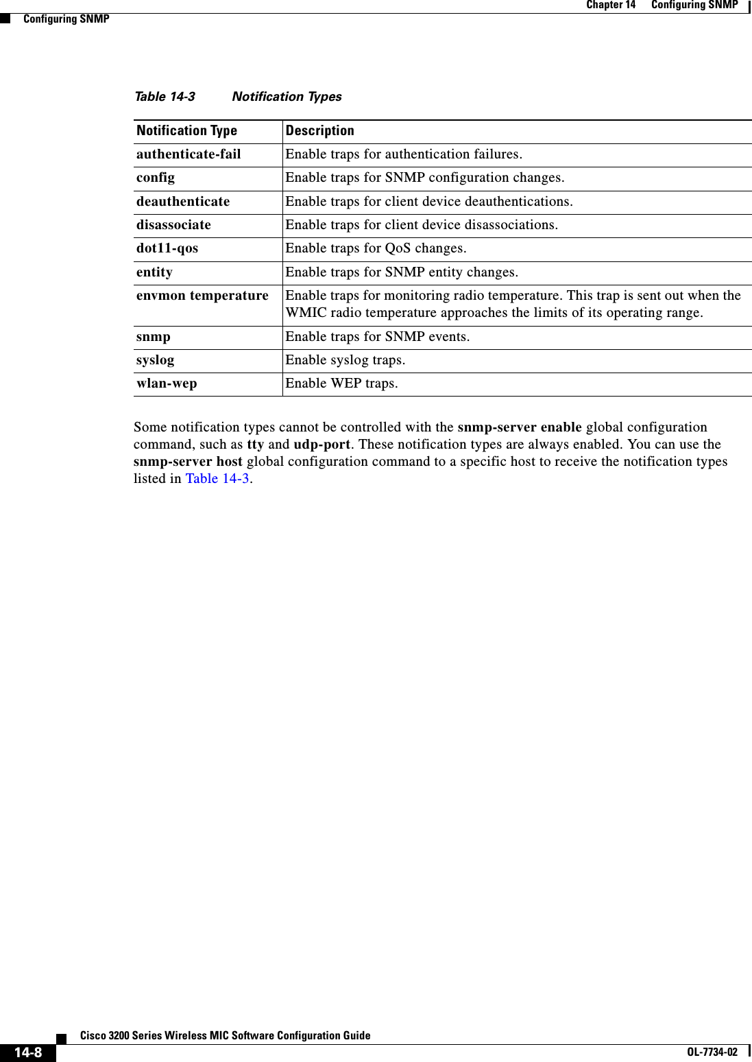
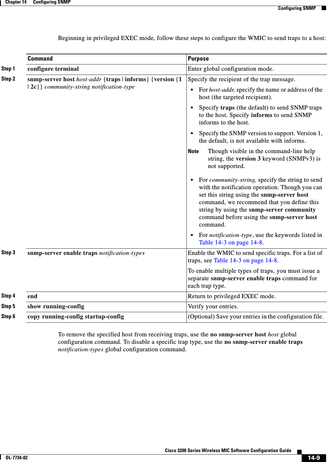
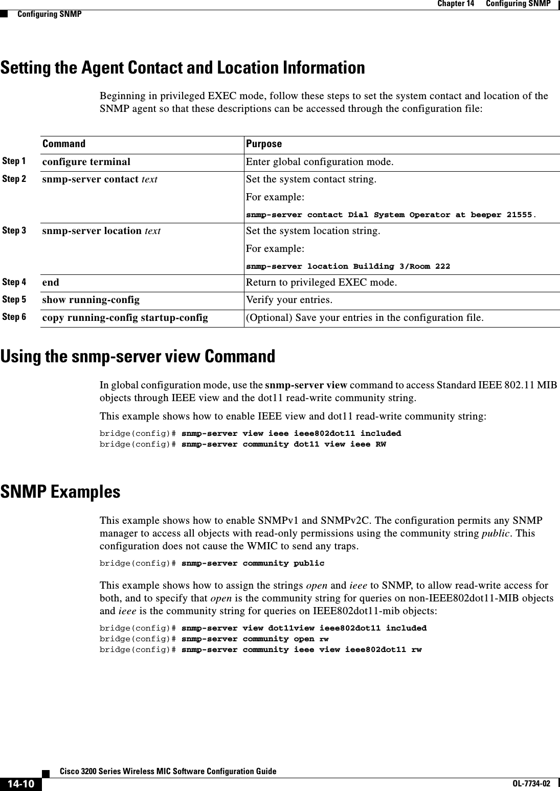
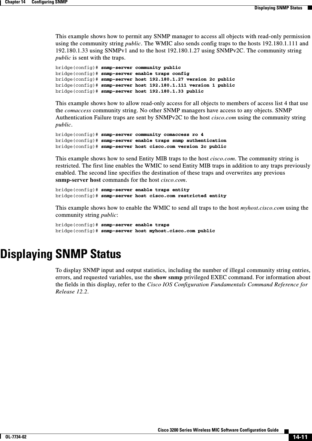

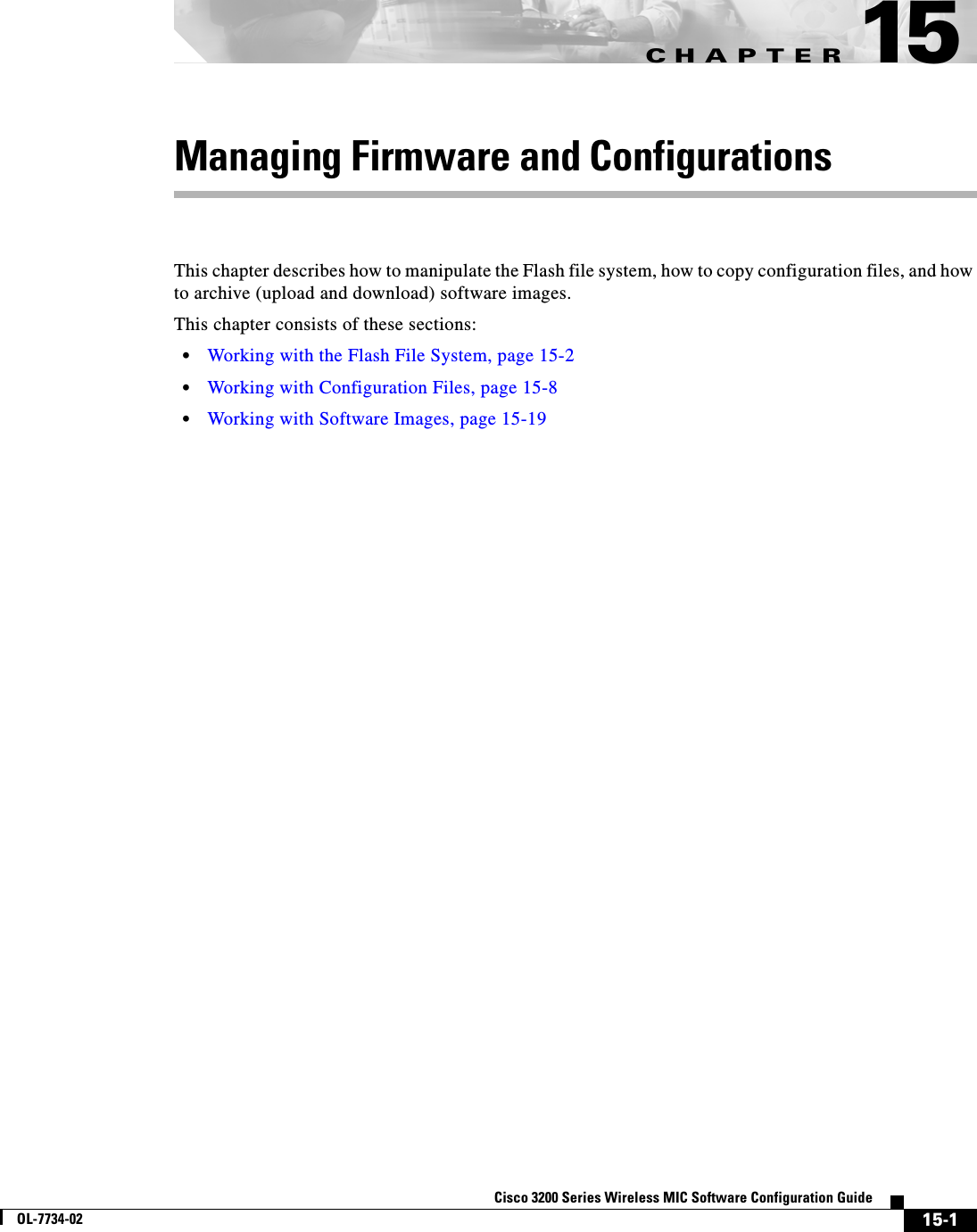
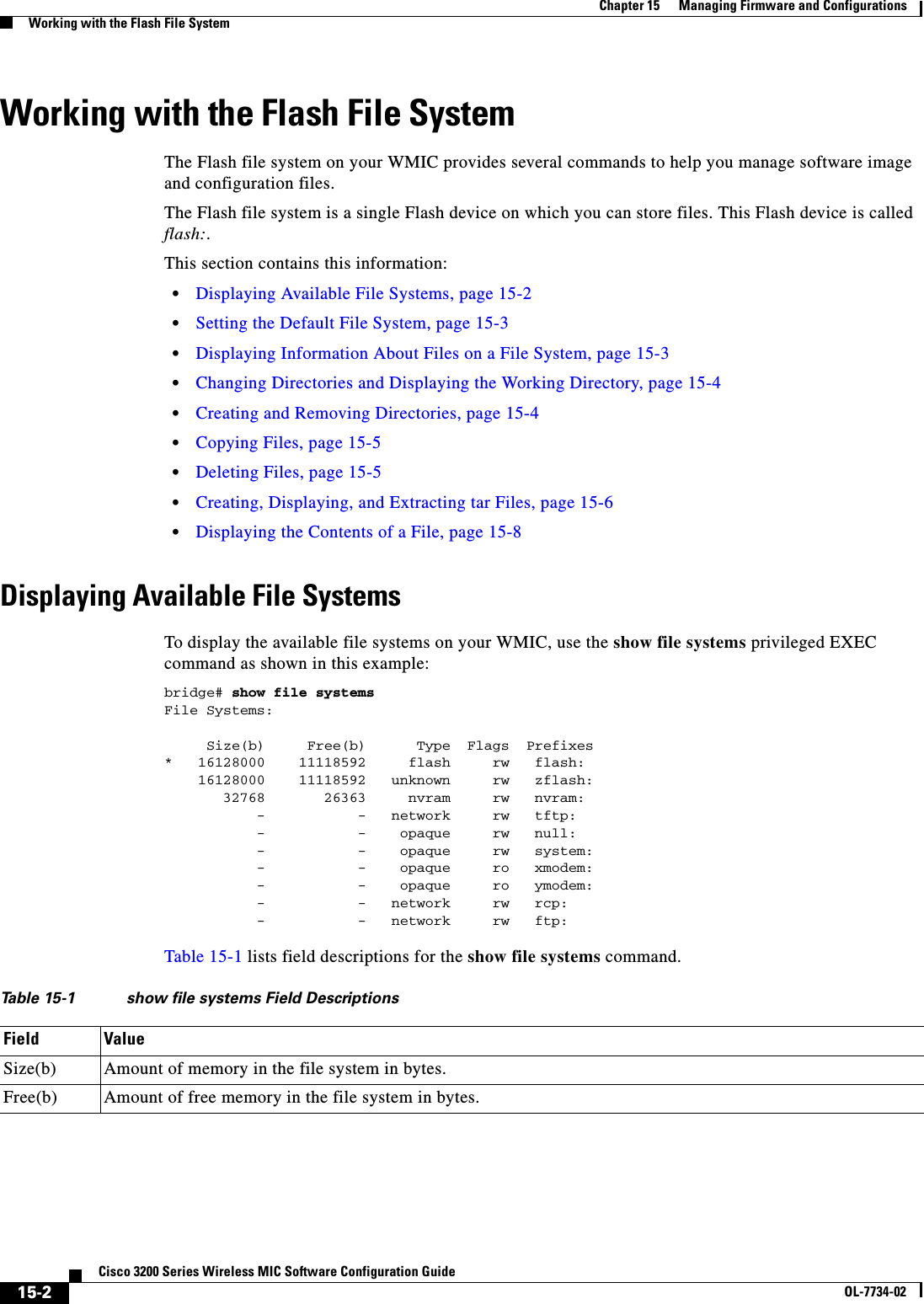
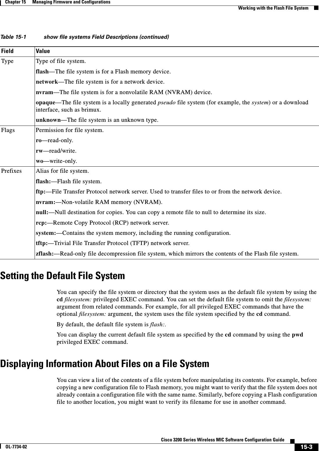
![15-4Cisco 3200 Series Wireless MIC Software Configuration GuideOL-7734-02Chapter 15 Managing Firmware and ConfigurationsWorking with the Flash File SystemTo display information about files on a file system, use one of the privileged EXEC commands in Table 15-2:Changing Directories and Displaying the Working DirectoryBeginning in privileged EXEC mode, follow these steps to change directories and display the working directory.Creating and Removing DirectoriesBeginning in privileged EXEC mode, follow these steps to create and remove a directory:To delete a directory with all its files and subdirectories, use the delete /force /recursive filesystem:/file-url privileged EXEC command. Table 15-2 Commands for Displaying Information About FilesCommand Descriptiondir [/all] [filesystem:][filename] Display a list of files on a file system.show file systems Display more information about each of the files on a file system.show file information file-url Display information about a specific file.show file descriptors Display a list of open file descriptors. File descriptors are the internal representations of open files. You can use this command to see if another user has a file open.Command PurposeStep 1 dir filesystem:Display the directories on the specified file system.For filesystem:, use flash: for the system board Flash device.Step 2 cd new_configs Change to the directory of interest.The command example shows how to change to the directory named new_configs.Step 3 pwd Display the working directory.Command PurposeStep 1 dir filesystem:Display the directories on the specified file system.For filesystem:, use flash: for the system board Flash device.Step 2 mkdir old_configs Create a new directory.The command example shows how to create the directory named old_configs.Directory names are case sensitive. Directory names are limited to 45 characters between the slashes (/); the name cannot contain control characters, spaces, deletes, slashes, quotes, semicolons, or colons.Step 3 dir filesystem:Verify your entry.](https://usermanual.wiki/Cisco-Systems/XSCLCR14/User-Guide-558354-Page-234.png)
![15-5Cisco 3200 Series Wireless MIC Software Configuration GuideOL-7734-02Chapter 15 Managing Firmware and ConfigurationsWorking with the Flash File SystemUse the /recursive keyword to delete the named directory and all subdirectories and the files contained in it. Use the /force keyword to suppress the prompting that confirms a deletion of each file in the directory. You are prompted only once at the beginning of this deletion process. Use the /force and /recursive keywords for deleting old software images that were installed by using the archive download-sw command but are no longer needed.For filesystem, use flash: for the system board Flash device. For file-url, enter the name of the directory to be deleted. All the files in the directory and the directory are removed.Caution When files and directories are deleted, their contents cannot be recovered.Copying FilesTo copy a file from a source to a destination, use the copy [/erase]source-url destination-url privileged EXEC command. For the source and destination URLs, you can use running-config and startup-configkeyword shortcuts. For example, the copy running-config startup-config command saves the currently running configuration file to the NVRAM section of Flash memory to be used as the configuration during system initialization.Network file system URLs include ftp:,rcp:, and tftp: and have the following syntax:•File Transfer Protocol (FTP)—ftp:[[//username [:password]@location]/directory]/filename•Remote Copy Protocol (RCP)—rcp:[[//username@location]/directory]/filename•Trivial File Transfer Protocol (TFTP)—tftp:[[//location]/directory]/filenameLocal writable file systems include flash:.Some invalid combinations of source and destination exist. Specifically, you cannot copy these combinations:•From a running configuration to a running configuration•From a startup configuration to a startup configuration•From a device to the same device (for example, the copy flash: flash: command is invalid)For specific examples of using the copy command with configuration files, see the “Working with Configuration Files” section on page 15-8.To copy software images either by downloading a new version or uploading the existing one, use the archive download-sw or the archive upload-sw privileged EXEC command. For more information, see the “Working with Software Images” section on page 15-19.Deleting FilesWhen you no longer need a file on a Flash memory device, you can permanently delete it. To delete a file or directory from a specified Flash device, use the delete [/force] [/recursive] [filesystem:]/file-urlprivileged EXEC command. Caution When files are deleted, their contents cannot be recovered.](https://usermanual.wiki/Cisco-Systems/XSCLCR14/User-Guide-558354-Page-235.png)
![15-6Cisco 3200 Series Wireless MIC Software Configuration GuideOL-7734-02Chapter 15 Managing Firmware and ConfigurationsWorking with the Flash File SystemUse the /recursive keyword for deleting a directory and all subdirectories and the files contained in it. Use the /force keyword to suppress the prompting that confirms a deletion of each file in the directory. You are prompted only once at the beginning of this deletion process. Use the /force and /recursivekeywords for deleting old software images that were installed by using the archive download-swcommand but are no longer needed.If you omit the filesystem: option, the WMIC uses the default device specified by the cd command. For file-url, you specify the path (directory) and the name of the file to be deleted.This example shows how to delete the file myconfig from the default Flash memory device:bridge# delete myconfigCreating, Displaying, and Extracting tar FilesYou can create a tar file and write files into it, list the files in a tar file, and extract the files from a tar file as described in the next sections.Creating a tar FileTo create a tar file and write files into it, use this privileged EXEC command:archive tar /create destination-url flash:/file-urlFor destination-url, specify the destination URL alias for the local or network file system and the name of the tar file to create. These options are supported:•For the local Flash file system, the syntax isflash:/file-url•For the File Transfer Protocol (FTP), the syntax is ftp:[[//username[:password]@location]/directory]/tar-filename.tar•For the Remote Copy Protocol (RCP), the syntax is rcp:[[//username@location]/directory]/tar-filename.tar•For the Trivial File Transfer Protocol (TFTP), the syntax is tftp:[[//location]/directory]/tar-filename.tarThe tar-filename.tar is the tar file to be created.For flash:/file-url, specify the location on the local Flash file system from which the new tar file is created. You can also specify an optional list of files or directories within the source directory to write to the new tar file. If none are specified, all files and directories at this level are written to the newly created tar file.This example shows how to create a tar file. This command writes the contents of the new-configsdirectory on the local Flash device to a file named saved.tar on the TFTP server at 172.20.10.30:bridge# archive tar /create tftp://172.20.10.30/saved.tar flash:/new-configs](https://usermanual.wiki/Cisco-Systems/XSCLCR14/User-Guide-558354-Page-236.png)
![15-7Cisco 3200 Series Wireless MIC Software Configuration GuideOL-7734-02Chapter 15 Managing Firmware and ConfigurationsWorking with the Flash File SystemDisplaying the Contents of a tar FileTo display the contents of a tar file on the screen, use this privileged EXEC command:archive tar /table source-urlFor source-url, specify the source URL alias for the local or network file system. These options are supported:•For the local Flash file system, the syntax isflash:•For the File Transfer Protocol (FTP), the syntax is ftp:[[//username[:password]@location]/directory]/tar-filename.tar•For the Remote Copy Protocol (RCP), the syntax is rcp:[[//username@location]/directory]/tar-filename.tar•For the Trivial File Transfer Protocol (TFTP), the syntax is tftp:[[//location]/directory]/tar-filename.tarThe tar-filename.tar is the tar file to display.You can also limit the display of the files by specifying an optional list of files or directories after the tar file; then only these files are displayed. If none are specified, all files and directories are displayed.This example shows how to display the contents of the c1200-k9w7-mx.122-8.JA.tar file that is in Flash memory:bridge# archive tar /table flash:c1200-k9w7-mx.122-8.JA.tarinfo (219 bytes)c1400-k9w7-mx.122-11.JA/ (directory)c1400-k9w7-mx.122-11.JA/html/ (directory)c1400-k9w7-mx.122-11.JA/html/foo.html (0 bytes)c1400-k9w7-mx.122-11.JA/c1200-k9w7-mx.122-8.JA.bin (610856 bytes)c1400-k9w7-mx.122-11.JA/info (219 bytes)info.ver (219 bytes)This example shows how to display only the c1200-k9w7-mx.122-8.JA/html directory and its contents:bridge# archive tar /table flash:c1200-k9w7-mx.122-8.JA/htmlc1400-k9w7-mx.122-11.JA/html/ (directory)c1400-k9w7-mx.122-11.JA/html/foo.html (0 bytes)Extracting a tar FileTo extract a tar file into a directory on the Flash file system, use this privileged EXEC command:archive tar /xtract source-url flash:/file-urlFor source-url, specify the source URL alias for the local or network file system. These options are supported:•For the local Flash file system, the syntax isflash:•For the File Transfer Protocol (FTP), the syntax is ftp:[[//username[:password]@location]/directory]/tar-filename.tar•For the Remote Copy Protocol (RCP), the syntax is rcp:[[//username@location]/directory]/tar-filename.tar•For the Trivial File Transfer Protocol (TFTP), the syntax is tftp:[[//location]/directory]/tar-filename.tar](https://usermanual.wiki/Cisco-Systems/XSCLCR14/User-Guide-558354-Page-237.png)
![15-8Cisco 3200 Series Wireless MIC Software Configuration GuideOL-7734-02Chapter 15 Managing Firmware and ConfigurationsWorking with Configuration FilesThe tar-filename.tar is the tar file from which to extract files.For flash:/file-url, specify the location on the local Flash file system into which the tar file is extracted. You can also specify an optional list of files or directories within the tar file for extraction. If none are specified, all files and directories are extracted.This example shows how to extract the contents of a tar file located on the TFTP server at 172.20.10.30. This command extracts just the new-configs directory into the root directory on the local Flash file system. The remaining files in the saved.tar file are ignored.bridge# archive tar /xtract tftp://172.20.10.30/saved.tar flash:/new-configsDisplaying the Contents of a FileTo display the contents of any readable file, including a file on a remote file system, use the more [/ascii|/binary | /ebcdic]file-url privileged EXEC command: This example shows how to display the contents of a configuration file on a TFTP server:bridge# more tftp://serverA/hampton/savedconfig!! Saved configuration on server!version 11.3service timestamps log datetime localtimeservice linenumberservice udp-small-serversservice pt-vty-logging!<output truncated>Working with Configuration FilesThis section describes how to create, load, and maintain configuration files. Configuration files contain commands entered to customize the function of the Cisco IOS software. To better benefit from these instructions, your WMIC contains a minimal default running configuration for interacting with the system software. You ca n c opy (download) configuration files from a TFTP, FTP, or RCP server to the running configuration of the WMIC for various reasons:•To restore a backed-up configuration file.•To use the configuration file for another bridge. For example, you might add another bridge to your network and want it to have a configuration similar to the original bridge. By copying the file to the new bridge, you can change the relevant parts rather than recreating the whole file.•To load the same configuration commands on all the access points in your network so that all the access points have similar configurations.You can copy (upload) configuration files from the WMIC to a file server by using TFTP, FTP, or RCP. You might perform this task to back up a current configuration file to a server before changing its contents so that you can later restore the original configuration file from the server. The protocol you use depends on which type of server you are using. The FTP and RCP transport mechanisms provide faster performance and more reliable delivery of data than TFTP. These improvements are possible because FTP and RCP are built on and use the Transmission Control Protocol/Internet Protocol (TCP/IP) stack, which is connection oriented.](https://usermanual.wiki/Cisco-Systems/XSCLCR14/User-Guide-558354-Page-238.png)
![15-11Cisco 3200 Series Wireless MIC Software Configuration GuideOL-7734-02Chapter 15 Managing Firmware and ConfigurationsWorking with Configuration Files•Ensure that the configuration file to be downloaded is in the correct directory on the TFTP server (usually /tftpboot on a UNIX workstation).•For download operations, ensure that the permissions on the file are set correctly. The permission on the file should be world-read.•Before uploading the configuration file, you might need to create an empty file on the TFTP server. To create an empty file, enter the touch filename command, where filename is the name of the file you will use when uploading it to the server.•During upload operations, if you are overwriting an existing file (including an empty file, if you had to create one) on the server, ensure that the permissions on the file are set correctly. Permissions on the file should be world-write.Downloading the Configuration File by Using TFTPTo configure the WMIC by using a configuration file downloaded from a TFTP server, follow these steps:Step 1 Copy the configuration file to the appropriate TFTP directory on the workstation.Step 2 Verify that the TFTP server is properly configured by referring to the “Preparing to Download or Upload a Configuration File by Using TFTP” section on page 15-10.Step 3 Log into the WMIC through a Telnet session.Step 4 Download the configuration file from the TFTP server to configure the WMIC. Specify the IP address or host name of the TFTP server and the name of the file to download.Use one of these privileged EXEC commands:•copy tftp:[[[//location]/directory]/filename]system:running-config•copy tftp:[[[//location]/directory]/filename]nvram:startup-configThe configuration file downloads, and the commands are executed as the file is parsed line-by-line.This example shows how to configure the software from the file tokyo-confg at IP address 172.16.2.155:bridge# copy tftp://172.16.2.155/tokyo-confg system:running-configConfigure using tokyo-confg from 172.16.2.155? [confirm] yBooting tokyo-confg from 172.16.2.155:!!! [OK - 874/16000 bytes]Uploading the Configuration File by Using TFTPTo upload a configuration file from a WMIC to a TFTP server for storage, follow these steps:Step 1 Verify that the TFTP server is properly configured by referring to the “Preparing to Download or Upload a Configuration File by Using TFTP” section on page 15-10.Step 2 Log into the WMIC through a Telnet session.Step 3 Upload the WMIC configuration to the TFTP server. Specify the IP address or host name of the TFTP server and the destination filename.](https://usermanual.wiki/Cisco-Systems/XSCLCR14/User-Guide-558354-Page-241.png)
![15-12Cisco 3200 Series Wireless MIC Software Configuration GuideOL-7734-02Chapter 15 Managing Firmware and ConfigurationsWorking with Configuration FilesUse one of these privileged EXEC commands:•copy system:running-config tftp:[[[//location]/directory]/filename]•copy nvram:startup-config tftp:[[[//location]/directory]/filename]The file is uploaded to the TFTP server.This example shows how to upload a configuration file from an WMIC to a TFTP server:bridge# copy system:running-config tftp://172.16.2.155/tokyo-configWrite file tokyo-confg on host 172.16.2.155? [confirm] y#Writing tokyo-confg!!! [OK]Copying Configuration Files by Using FTPYou can copy configuration files to or from an FTP server.The FTP protocol requires a client to send a remote username and password on each FTP request to a server. When you copy a configuration file from the WMIC to a server by using FTP, the Cisco IOS software sends the first valid username in this list:•The username specified in the copy command if a username is specified.•The username set by the ip ftp username username global configuration command if the command is configured.•Anonymous.The WMIC sends the first valid password in this list:•The password specified in the copy command if a password is specified.•The password set by the ip ftp password password global configuration command if the command is configured.•The WMIC forms a password named username@apname.domain. The variable username is the username associated with the current session, apname is the configured host name, and domain is the domain of the WMIC.The username and password must be associated with an account on the FTP server. If you are writing to the server, the FTP server must be properly configured to accept your FTP write request.Use the ip ftp username and ip ftp password commands to specify a username and password for all copies. Include the username in the copy command if you want to specify only a username for that copy operation.If the server has a directory structure, the configuration file is written to or copied from the directory associated with the username on the server. For example, if the configuration file resides in the home directory of a user on the server, specify that user's name as the remote username. For more information, refer to the documentation for your FTP server.This section includes this information:•Preparing to Download or Upload a Configuration File by Using FTP, page 15-13•Downloading a Configuration File by Using FTP, page 15-13•Uploading a Configuration File by Using FTP, page 15-14](https://usermanual.wiki/Cisco-Systems/XSCLCR14/User-Guide-558354-Page-242.png)
![15-13Cisco 3200 Series Wireless MIC Software Configuration GuideOL-7734-02Chapter 15 Managing Firmware and ConfigurationsWorking with Configuration FilesPreparing to Download or Upload a Configuration File by Using FTPBefore you begin downloading or uploading a configuration file by using FTP, perform these tasks:•Ensure that the WMIC has a route to the FTP server. The WMIC and the FTP server must be in the same subnetwork if you do not have a router to route traffic between subnets. Check connectivity to the FTP server by using the ping command.•If you are accessing the WMIC through a Telnet session and you do not have a valid username, make sure that the current FTP username is the one that you want to use for the FTP download. You can enter the show users privileged EXEC command to view the valid username. If you do not want to use this username, create a new FTP username by using the ip ftp username username global configuration command during all copy operations. The new username is stored in NVRAM. If you are accessing the WMIC through a Telnet session and you have a valid username, this username is used, and you do not need to set the FTP username. Include the username in the copy command if you want to specify a username for only that copy operation. •When you upload a configuration file to the FTP server, it must be properly configured to accept the write request from the user on the WMIC.For more information, refer to the documentation for your FTP server.Downloading a Configuration File by Using FTPBeginning in privileged EXEC mode, follow these steps to download a configuration file by using FTP:This example shows how to copy a configuration file named host1-confg from the netadmin1 directory on the remote server with an IP address of 172.16.101.101 and to load and run those commands on the WMIC:bridge# copy ftp://netadmin1:mypass@172.16.101.101/host1-confg system:running-configConfigure using host1-confg from 172.16.101.101? [confirm]Command PurposeStep 1 Verify that the FTP server is properly configured by referring to the “Preparing to Download or Upload a Configuration File by Using FTP” section on page 15-13.Step 2 Log into the WMIC through a Telnet session.Step 3 configure terminal Enter global configuration mode on the WMIC.This step is required only if you override the default remote username or password (see Steps 4, 5, and 6). Step 4 ip ftp username username (Optional) Change the default remote username.Step 5 ip ftp password password (Optional) Change the default password.Step 6 end Return to privileged EXEC mode. Step 7 copyftp:[[[//[username[:password]@]location]/directory]/filename]system:running-configorcopyftp:[[[//[username[:password]@]location]/directory]/filename]nvram:startup-configUsing FTP, copy the configuration file from a network server to the running configuration or to the startup configuration file.](https://usermanual.wiki/Cisco-Systems/XSCLCR14/User-Guide-558354-Page-243.png)
![15-14Cisco 3200 Series Wireless MIC Software Configuration GuideOL-7734-02Chapter 15 Managing Firmware and ConfigurationsWorking with Configuration FilesConnected to 172.16.101.101Loading 1112 byte file host1-confg:![OK]bridge#%SYS-5-CONFIG: Configured from host1-config by ftp from 172.16.101.101This example shows how to specify a remote username of netadmin1. The software copies the configuration file host2-confg from the netadmin1 directory on the remote server with an IP address of 172.16.101.101 to the WMIC startup configuration.bridge# configure terminalbridge(config)# ip ftp username netadmin1bridge(config)# ip ftp password mypassbridge(config)# endbridge# copy ftp: nvram:startup-configAddress of remote host [255.255.255.255]? 172.16.101.101Name of configuration file[rtr2-confg]? host2-confgConfigure using host2-confg from 172.16.101.101?[confirm]Connected to 172.16.101.101Loading 1112 byte file host2-confg:![OK][OK]bridge#%SYS-5-CONFIG_NV:Non-volatile store configured from host2-config by ftp from 172.16.101.101Uploading a Configuration File by Using FTPBeginning in privileged EXEC mode, follow these steps to upload a configuration file by using FTP:This example shows how to copy the running configuration file named ap2-confg to the netadmin1directory on the remote host with an IP address of 172.16.101.101: bridge# copy system:running-config ftp://netadmin1:mypass@172.16.101.101/ap2-confgWrite file ap2-confg on host 172.16.101.101?[confirm]Command PurposeStep 1 Verify that the FTP server is properly configured by referring to the “Preparing to Download or Upload a Configuration File by Using FTP” section on page 15-13.Step 2 Log into the WMIC through a Telnet session.Step 3 configure terminal Enter global configuration mode.This step is required only if you override the default remote username or password (see Steps 4, 5, and 6). Step 4 ip ftp username username (Optional) Change the default remote username.Step 5 ip ftp password password (Optional) Change the default password.Step 6 end Return to privileged EXEC mode. Step 7 copy system:running-config ftp:[[[//[username[:password]@]location]/directory]/filename]orcopy nvram:startup-config ftp:[[[//[username[:password]@]location]/directory]/filename]Using FTP, store the WMIC running or startup configuration file to the specified location.](https://usermanual.wiki/Cisco-Systems/XSCLCR14/User-Guide-558354-Page-244.png)
![15-15Cisco 3200 Series Wireless MIC Software Configuration GuideOL-7734-02Chapter 15 Managing Firmware and ConfigurationsWorking with Configuration FilesBuilding configuration...[OK]Connected to 172.16.101.101bridge#This example shows how to store a startup configuration file on a server by using FTP to copy the file:bridge# configure terminalbridge(config)# ip ftp username netadmin2bridge(config)# ip ftp password mypassbridge(config)# endbridge# copy nvram:startup-config ftp:Remote host[]? 172.16.101.101Name of configuration file to write [ap2-confg]?Write file ap2-confg on host 172.16.101.101?[confirm]![OK]Copying Configuration Files by Using RCPThe Remote Copy Protocol (RCP) provides another method of downloading, uploading, and copying configuration files between remote hosts and the WMIC. Unlike TFTP, which uses User Datagram Protocol (UDP), a connectionless protocol, RCP uses TCP, which is connection-oriented. To use RCP to copy files, the server from or to which you will be copying files must support RCP. The RCP copy commands rely on the rsh server (or daemon) on the remote system. To copy files by using RCP, you do not need to create a server for file distribution as you do with TFTP. You only need to have access to a server that supports the remote shell (rsh). (Most UNIX systems support rsh.) Because you are copying a file from one place to another, you must have read permission on the source file and write permission on the destination file. If the destination file does not exist, RCP creates it for you.The RCP requires a client to send a remote username with each RCP request to a server. When you copy a configuration file from the WMIC to a server, the Cisco IOS software sends the first valid username in this list:•The username specified in the copy command if a username is specified.•The username set by the ip rcmd remote-username username global configuration command if the command is configured.•The remote username associated with the current TTY (terminal) process. For example, if the user is connected to the router through Telnet and was authenticated through the username command, the WMIC software sends the Telnet username as the remote username. •The WMIC host name.For a successful RCP copy request, you must define an account on the network server for the remote username. If the server has a directory structure, the configuration file is written to or copied from the directory associated with the remote username on the server. For example, if the configuration file is in the home directory of a user on the server, specify that user's name as the remote username. This section includes this information:•Preparing to Download or Upload a Configuration File by Using RCP, page 15-16•Downloading a Configuration File by Using RCP, page 15-16•Uploading a Configuration File by Using RCP, page 15-17](https://usermanual.wiki/Cisco-Systems/XSCLCR14/User-Guide-558354-Page-245.png)
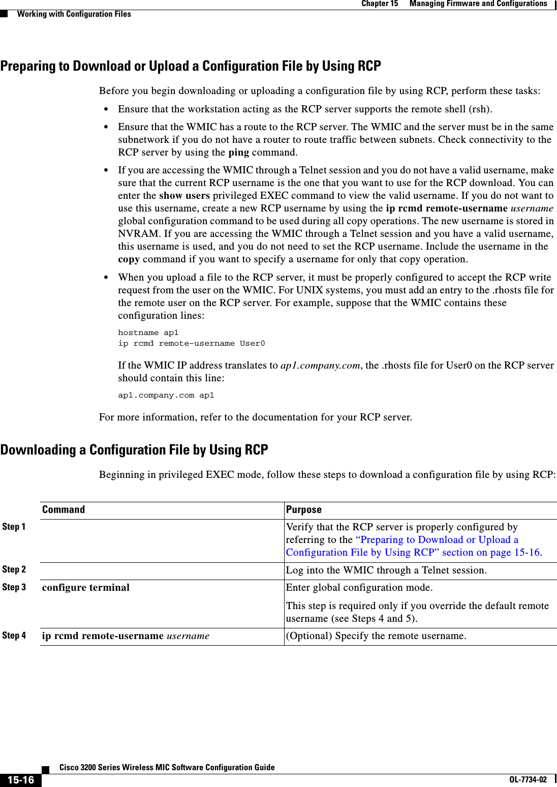
![15-17Cisco 3200 Series Wireless MIC Software Configuration GuideOL-7734-02Chapter 15 Managing Firmware and ConfigurationsWorking with Configuration FilesThis example shows how to copy a configuration file named host1-confg from the netadmin1 directory on the remote server with an IP address of 172.16.101.101 and load and run those commands on the WMIC:bridge# copy rcp://netadmin1@172.16.101.101/host1-confg system:running-configConfigure using host1-confg from 172.16.101.101? [confirm]Connected to 172.16.101.101Loading 1112 byte file host1-confg:![OK]bridge#%SYS-5-CONFIG: Configured from host1-config by rcp from 172.16.101.101This example shows how to specify a remote username of netadmin1. Then it copies the configuration file host2-confg from the netadmin1 directory on the remote server with an IP address of 172.16.101.101 to the startup configuration:bridge# configure terminalbridge(config)# ip rcmd remote-username netadmin1bridge(config)# endbridge# copy rcp: nvram:startup-configAddress of remote host [255.255.255.255]? 172.16.101.101Name of configuration file[rtr2-confg]? host2-confgConfigure using host2-confg from 172.16.101.101?[confirm]Connected to 172.16.101.101Loading 1112 byte file host2-confg:![OK][OK]bridge#%SYS-5-CONFIG_NV:Non-volatile store configured from host2-config by rcp from 172.16.101.101Uploading a Configuration File by Using RCPBeginning in privileged EXEC mode, follow these steps to upload a configuration file by using RCP:Step 5 end Return to privileged EXEC mode. Step 6 copyrcp:[[[//[username@]location]/directory]/filename]system:running-configorcopyrcp:[[[//[username@]location]/directory]/filename]nvram:startup-configUsing RCP, copy the configuration file from a network server to the running configuration or to the startup configuration file. Command PurposeCommand PurposeStep 1 Verify that the RCP server is properly configured by referring to the “Preparing to Download or Upload a Configuration File by Using RCP” section on page 15-16.Step 2 Log into the WMIC through a Telnet session.Step 3 configure terminal Enter global configuration mode.This step is required only if you override the default remote username (see Steps 4 and 5). Step 4 ip rcmd remote-username username (Optional) Specify the remote username.](https://usermanual.wiki/Cisco-Systems/XSCLCR14/User-Guide-558354-Page-247.png)
![15-18Cisco 3200 Series Wireless MIC Software Configuration GuideOL-7734-02Chapter 15 Managing Firmware and ConfigurationsWorking with Configuration FilesThis example shows how to copy the running configuration file named ap2-confg to the netadmin1directory on the remote host with an IP address of 172.16.101.101: bridge# copy system:running-config rcp://netadmin1@172.16.101.101/ap2-confgWrite file br-confg on host 172.16.101.101?[confirm]Building configuration...[OK]Connected to 172.16.101.101bridge#This example shows how to store a startup configuration file on a server:bridge# configure terminalbridge(config)# ip rcmd remote-username netadmin2bridge(config)# endbridge# copy nvram:startup-config rcp:Remote host[]? 172.16.101.101Name of configuration file to write [ap2-confg]?Write file ap2-confg on host 172.16.101.101?[confirm]![OK]Clearing Configuration InformationThis section describes how to clear configuration information. Deleting a Stored Configuration FileCaution You cannot restore a file after it has been deleted. To delete a saved configuration from Flash memory, use the delete flash:filename privileged EXEC command. Depending on the setting of the file prompt global configuration command, you might be prompted for confirmation before you delete a file. By default, the WMIC prompts for confirmation on destructive file operations. For more information about the file prompt command, refer to the Cisco IOS Command Reference for Release 12.1.Step 5 end Return to privileged EXEC mode. Step 6 copy system:running-config rcp:[[[//[username@]location]/directory]/filename]orcopy nvram:startup-config rcp:[[[//[username@]location]/directory]/filename]Using RCP, copy the configuration file from an WMIC running or startup configuration file to a network server.Command Purpose](https://usermanual.wiki/Cisco-Systems/XSCLCR14/User-Guide-558354-Page-248.png)
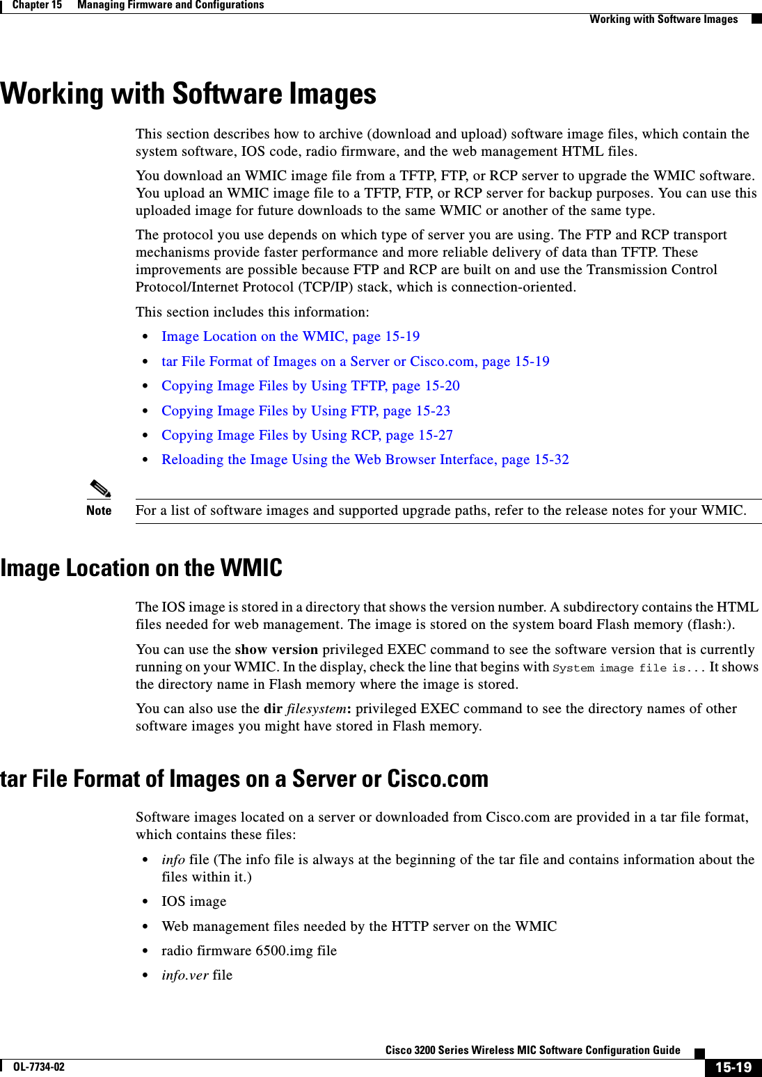
![15-21Cisco 3200 Series Wireless MIC Software Configuration GuideOL-7734-02Chapter 15 Managing Firmware and ConfigurationsWorking with Software Images•During upload operations, if you are overwriting an existing file (including an empty file, if you had to create one) on the server, ensure that the permissions on the file are set correctly. Permissions on the file should be world-write.Downloading an Image File by Using TFTPYou can download a new image file and replace the current image or keep the current image. Caution For the download and upload algorithms to operate properly, do not rename image directories.Beginning in privileged EXEC mode, follow Steps 1 through 3 to download a new image from a TFTP server and overwrite the existing image. Note To avoid an unsuccessful download, use the archive download-sw /safe command, which downloads the image first and does not delete the current running version until the download succeeds.Command PurposeStep 1 . Copy the image to the appropriate TFTP directory on the workstation. Make sure the TFTP server is properly configured; see the “Preparing to Download or Upload an Image File by Using TFTP” section on page 15-20Step 2 Log into the WMIC through a Telnet session.Step 3 archive download-sw /overwrite /reload tftp:[[//location]/directory]/image-nameDownload the image file from the TFTP server to the WMIC, and overwrite the current image.•The /overwrite option overwrites the software image in Flash with the downloaded image.•The /reload option reloads the system after downloading the image unless the configuration has been changed and not saved.•For location, specify the IP address of the TFTP server.•For directory/image-name, specify the directory (optional) and the image to download. Directory and image names are case sensitive.Step 4 archive download-sw /leave-old-sw /reload tftp:[[//location]/directory]/image-nameDownload the image file from the TFTP server to the WMIC, and keep the current image.•The /leave-old-sw option keeps the old software version after a download.•The /reload option reloads the system after downloading the image unless the configuration has been changed and not saved.•For location, specify the IP address of the TFTP server.•For directory/image-name, specify the directory (optional) and the image to download. Directory and image names are case sensitive.](https://usermanual.wiki/Cisco-Systems/XSCLCR14/User-Guide-558354-Page-251.png)
![15-22Cisco 3200 Series Wireless MIC Software Configuration GuideOL-7734-02Chapter 15 Managing Firmware and ConfigurationsWorking with Software ImagesThe download algorithm verifies that the image is appropriate for the WMIC model and that enough DRAM is present, or it aborts the process and reports an error. If you specify the /overwrite option, the download algorithm removes the existing image on the Flash device whether or not it is the same as the new one, downloads the new image, and then reloads the software.Note If the Flash device has sufficient space to hold two images and you want to overwrite one of these images with the same version, you must specify the /overwrite option.If you specify the /leave-old-sw, the existing files are not removed. If there is not enough space to install the new image and keep the current running image, the download process stops, and an error message is displayed.The algorithm installs the downloaded image on the system board Flash device (flash:). The image is placed into a new directory named with the software version string, and the system boot path variable is updated to point to the newly installed image.If you kept the old image during the download process (you specified the /leave-old-sw keyword), you can remove it by entering the delete /force /recursive filesystem:/file-url privileged EXEC command. For filesystem, use flash: for the system board Flash device. For file-url, enter the directory name of the old image. All the files in the directory and the directory are removed.Uploading an Image File by Using TFTPYou can upload an image from the WMIC to a TFTP server. You can later download this image to the WMIC or to another WMIC of the same type.Caution For the download and upload algorithms to operate properly, do not rename image directories.Beginning in privileged EXEC mode, follow these steps to upload an image to a TFTP server:The archive upload-sw privileged EXEC command builds an image file on the server by uploading these files in order: info, the IOS image, the HTML files, and info.ver. After these files are uploaded, the upload algorithm creates the tar file format. Command PurposeStep 1 Make sure the TFTP server is properly configured; see the “Preparing to Download or Upload an Image File by Using TFTP” section on page 15-20.Step 1 Log into the WMIC through a Telnet session.Step 2 archive upload-swtftp:[[//location]/directory]/image-name.tarUpload the currently running WMIC image to the TFTP server. •For location, specify the IP address of the TFTP server.•For directory/image-name.tar, specify the directory (optional) and the name of the software image to be uploaded. Directory and image names are case sensitive. The image-name.tar is the name of the software image to be stored on the server.](https://usermanual.wiki/Cisco-Systems/XSCLCR14/User-Guide-558354-Page-252.png)
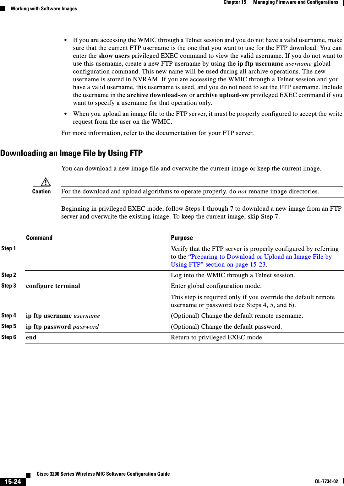
![15-25Cisco 3200 Series Wireless MIC Software Configuration GuideOL-7734-02Chapter 15 Managing Firmware and ConfigurationsWorking with Software ImagesNote To avoid an unsuccessful download, use the archive download-sw /safe command, which downloads the image first and does not delete the current running version until the download succeeds.The download algorithm verifies that the image is appropriate for the WMIC model and that enough DRAM is present, or it aborts the process and reports an error. If you specify the /overwrite option, the download algorithm removes the existing image on the Flash device, whether or not it is the same as the new one, downloads the new image, and then reloads the software.Note If the Flash device has sufficient space to hold two images and you want to overwrite one of these images with the same version, you must specify the /overwrite option.Step 7 archive download-sw /overwrite /reload ftp:[[//username[:password]@location]/directory]/image-name.tarDownload the image file from the FTP server to the WMIC, and overwrite the current image.•The /overwrite option overwrites the software image in Flash with the downloaded image.•The /reload option reloads the system after downloading the image unless the configuration has been changed and not saved.•For //username[:password], specify the username and password; these must be associated with an account on the FTP server. For more information, see the “Preparing to Download or Upload an Image File by Using FTP” section on page 15-23.•For @location, specify the IP address of the FTP server.•For directory/image-name.tar, specify the directory (optional) and the image to download. Directory and image names are case sensitive.Step 8 archive download-sw /leave-old-sw /reload ftp:[[//username[:password]@location]/directory]/image-name.tarDownload the image file from the FTP server to the WMIC, and keep the current image.•The /leave-old-sw option keeps the old software version after a download.•The /reload option reloads the system after downloading the image unless the configuration has been changed and not saved.•For //username[:password], specify the username and password. These must be associated with an account on the FTP server. For more information, see the “Preparing to Download or Upload an Image File by Using FTP” section on page 15-23.•For @location, specify the IP address of the FTP server.•For directory/image-name.tar, specify the directory (optional) and the image to download. Directory and image names are case sensitive.Command Purpose](https://usermanual.wiki/Cisco-Systems/XSCLCR14/User-Guide-558354-Page-255.png)
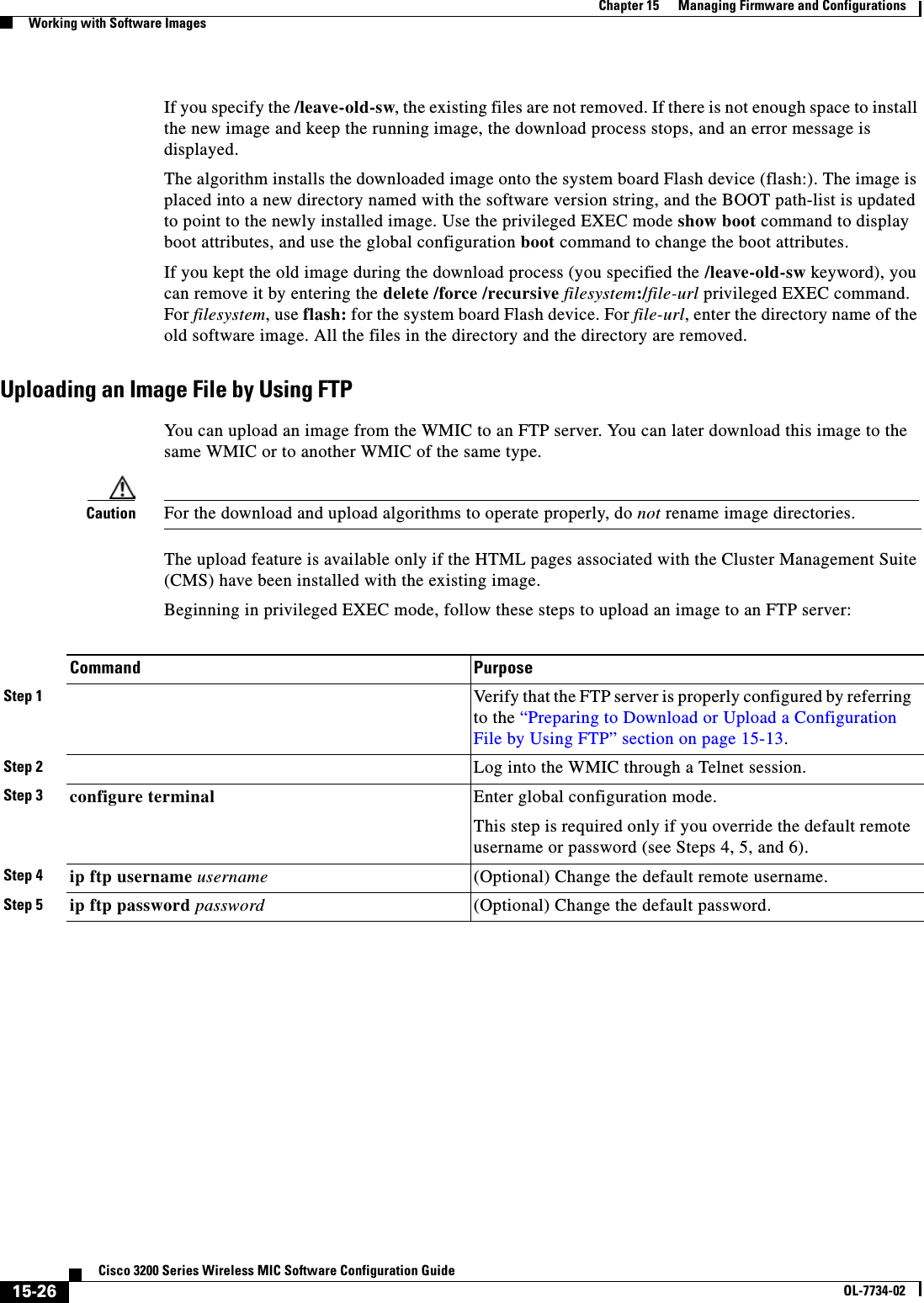
![15-27Cisco 3200 Series Wireless MIC Software Configuration GuideOL-7734-02Chapter 15 Managing Firmware and ConfigurationsWorking with Software ImagesThe archive upload-sw command builds an image file on the server by uploading these files in order: info, the IOS image, the HTML files, and info.ver. After these files are uploaded, the upload algorithm creates the tar file format. Copying Image Files by Using RCPYou can download a WMIC image from an RCP server or upload the image from the WMIC to an RCP server.You download a WMIC image file from a server to upgrade the WMIC software. You can overwrite the current image with the new one or keep the current image after a download.You upload a WMIC image file to a server for backup purposes. You can use this uploaded image for future downloads to the same WMIC or another device of the same type.This section includes this information:•Preparing to Download or Upload an Image File by Using RCP, page 15-27•Downloading an Image File by Using RCP, page 15-29•Uploading an Image File by Using RCP, page 15-31Preparing to Download or Upload an Image File by Using RCPRCP provides another method of downloading and uploading image files between remote hosts and the WMIC. Unlike TFTP, which uses User Datagram Protocol (UDP), a connectionless protocol, RCP uses TCP, which is connection-oriented. To use RCP to copy files, the server from or to which you will be copying files must support RCP. The RCP copy commands rely on the rsh server (or daemon) on the remote system. To copy files by using RCP, you do not need to create a server for file distribution as you do with TFTP. You only need to have access to a server that supports the remote shell (rsh). (Most UNIX systems support rsh.) Because you are copying a file from one place to another, you must have read permission on the source file and write permission on the destination file. If the destination file does not exist, RCP creates it for you.Step 6 end Return to privileged EXEC mode. Step 7 archive upload-sw ftp:[[//[username[:password]@]location]/directory]/image-name.tarUpload the currently running WMIC image to the FTP server. •For //username:password, specify the username and password. These must be associated with an account on the FTP server. For more information, see the “Preparing to Download or Upload an Image File by Using FTP” section on page 15-23.•For @location, specify the IP address of the FTP server.•For /directory/image-name.tar, specify the directory (optional) and the name of the software image to be uploaded. Directory and image names are case sensitive. The image-name.tar is the name of the software image to be stored on the server.Command Purpose](https://usermanual.wiki/Cisco-Systems/XSCLCR14/User-Guide-558354-Page-257.png)
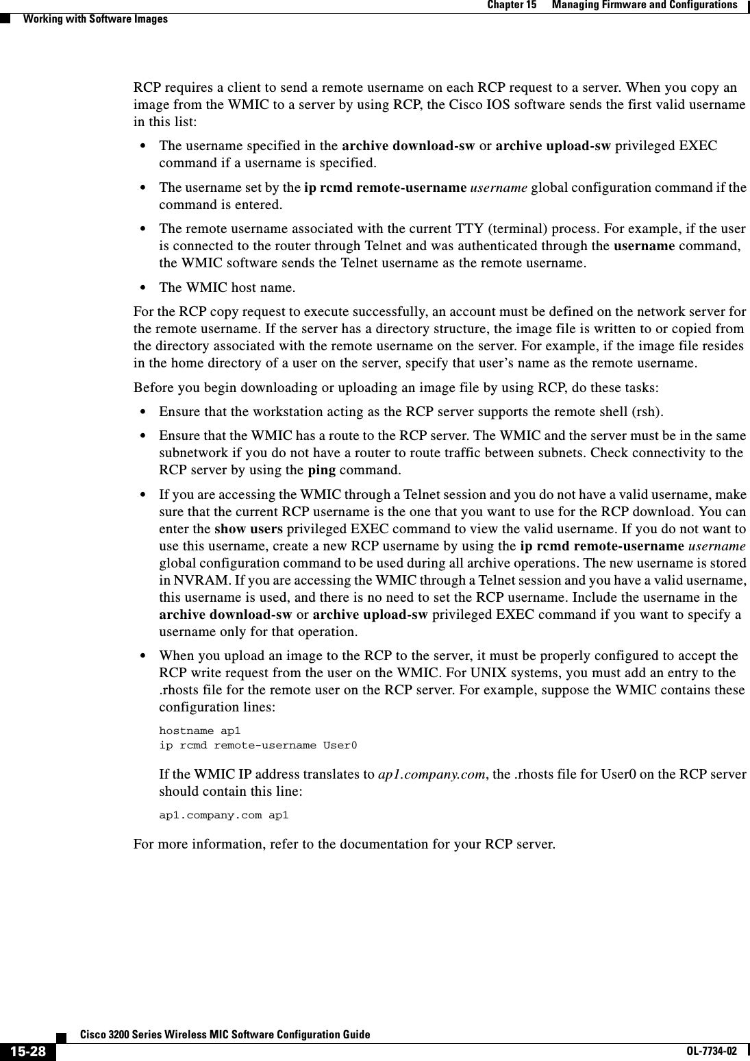
![15-29Cisco 3200 Series Wireless MIC Software Configuration GuideOL-7734-02Chapter 15 Managing Firmware and ConfigurationsWorking with Software ImagesDownloading an Image File by Using RCPYou can download a new image file and replace or keep the current image. Caution For the download and upload algorithms to operate properly, do not rename image directories.Beginning in privileged EXEC mode, follow Steps 1 through 6 to download a new image from an RCP server and overwrite the existing image. To keep the current image, skip Step 6.Command PurposeStep 1 Verify that the RCP server is properly configured by referring to the “Preparing to Download or Upload an Image File by Using RCP” section on page 15-27.Step 2 Log into the WMIC through a Telnet session.Step 3 configure terminal Enter global configuration mode.This step is required only if you override the default remote username (see Steps 4 and 5). Step 4 ip rcmd remote-username username (Optional) Specify the remote username.Step 5 end Return to privileged EXEC mode. Step 6 archive download-sw /overwrite /reload rcp:[[[//[username@]location]/directory]/image-name.tar]Download the image file from the RCP server to the WMIC, and overwrite the current image.•The /overwrite option overwrites the software image in Flash with the downloaded image.•The /reload option reloads the system after downloading the image unless the configuration has been changed and not saved.•For //username, specify the username. For the RCP copy request to execute successfully, an account must be defined on the network server for the remote username. For more information, see the “Preparing to Download or Upload an Image File by Using RCP” section on page 15-27.•For @location, specify the IP address of the RCP server.•For /directory/image-name.tar, specify the directory (optional) and the image to download. Directory and image names are case sensitive.](https://usermanual.wiki/Cisco-Systems/XSCLCR14/User-Guide-558354-Page-259.png)
![15-30Cisco 3200 Series Wireless MIC Software Configuration GuideOL-7734-02Chapter 15 Managing Firmware and ConfigurationsWorking with Software ImagesNote To avoid an unsuccessful download, use the archive download-sw /safe command, which downloads the image first and does not delete the current running version until the download succeeds.The download algorithm verifies that the image is appropriate for the WMIC model and that enough DRAM is present, or it aborts the process and reports an error. If you specify the /overwrite option, the download algorithm removes the existing image on the Flash device whether or not it is the same as the new one, downloads the new image, and then reloads the software.Note If the Flash device has sufficient space to hold two images and you want to overwrite one of these images with the same version, you must specify the /overwrite option.If you specify the /leave-old-sw, the existing files are not removed. If there is not enough room to install the new image an keep the running image, the download process stops, and an error message is displayed.The algorithm installs the downloaded image onto the system board Flash device (flash:). The image is placed into a new directory named with the software version string, and the BOOT environment variable is updated to point to the newly installed image.If you kept the old software during the download process (you specified the /leave-old-sw keyword), you can remove it by entering the delete /force /recursive filesystem:/file-url privileged EXEC command. For filesystem, use flash: for the system board Flash device. For file-url, enter the directory name of the old software image. All the files in the directory and the directory are removed.Step 7 archive download-sw /leave-old-sw /reload rcp:[[[//[username@]location]/directory]/image-name.tar]Download the image file from the RCP server to the WMIC, and keep the current image.•The /leave-old-sw option keeps the old software version after a download.•The /reload option reloads the system after downloading the image unless the configuration has been changed and not saved.•For //username, specify the username. For the RCP copy request to execute, an account must be defined on the network server for the remote username. For more information, see the “Preparing to Download or Upload an Image File by Using RCP” section on page 15-27.•For @location, specify the IP address of the RCP server.•For /directory]/image-name.tar, specify the directory (optional) and the image to download. Directory and image names are case sensitive.Command Purpose](https://usermanual.wiki/Cisco-Systems/XSCLCR14/User-Guide-558354-Page-260.png)
![15-31Cisco 3200 Series Wireless MIC Software Configuration GuideOL-7734-02Chapter 15 Managing Firmware and ConfigurationsWorking with Software ImagesUploading an Image File by Using RCPYou can upload an image from the WMIC to an RCP server. You can later download this image to the same WMIC or to another WMIC of the same type.Caution For the download and upload algorithms to operate properly, do not rename image directories.The upload feature is available only if the HTML pages associated with the Cluster Management Suite (CMS) have been installed with the existing image.Beginning in privileged EXEC mode, follow these steps to upload an image to an RCP server:The archive upload-sw privileged EXEC command builds an image file on the server by uploading these files in order: info, the IOS image, the HTML files, and info.ver. After these files are uploaded, the upload algorithm creates the tar file format. Command PurposeStep 1 Verify that the RCP server is properly configured by referring to the “Preparing to Download or Upload an Image File by Using RCP” section on page 15-27.Step 2 Log into the WMIC through a Telnet session.Step 3 configure terminal Enter global configuration mode.This step is required only if you override the default remote username (see Steps 4 and 5). Step 4 ip rcmd remote-username username (Optional) Specify the remote username.Step 5 end Return to privileged EXEC mode. Step 6 archive upload-sw rcp:[[[//[username@]location]/directory]/image-name.tar]Upload the currently running WMIC image to the RCP server. •For //username, specify the username; for the RCP copy request to execute, an account must be defined on the network server for the remote username. For more information, see the “Preparing to Download or Upload an Image File by Using RCP” section on page 15-27.•For @location, specify the IP address of the RCP server.•For /directory]/image-name.tar, specify the directory (optional) and the name of the software image to be uploaded. Directory and image names are case sensitive.•The image-name.tar is the name of software image to be stored on the server.](https://usermanual.wiki/Cisco-Systems/XSCLCR14/User-Guide-558354-Page-261.png)
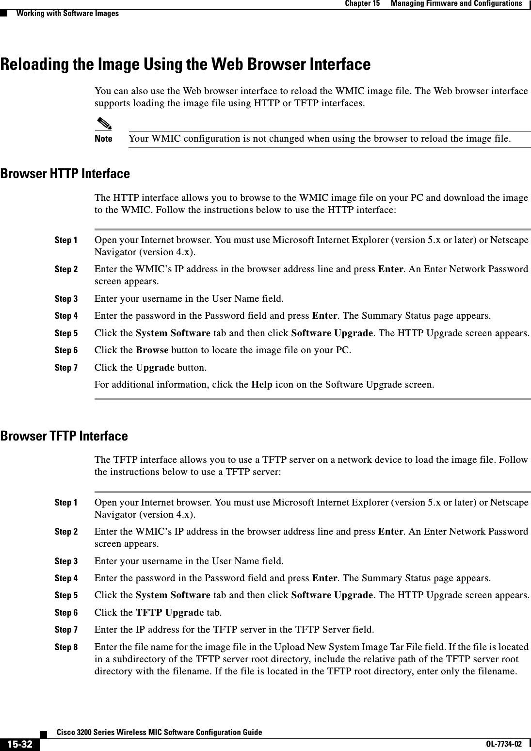


![16-2Cisco 3200 Series Wireless MIC Software Configuration GuideOL-7734-02Chapter 16 Configuring System Message LoggingUnderstanding System Message LoggingUnderstanding System Message LoggingBy default, devices send the output from system messages and debug privileged EXEC commands to a logging process. The logging process controls the distribution of logging messages to various destinations, such as the logging buffer, terminal lines, or a UNIX syslog server, depending on your configuration. The process also sends messages to the console. Note The syslog format is compatible with 4.3 BSD UNIX.When the logging process is disabled, messages are sent only to the console. The messages are sent as they are generated, so message and debug output are interspersed with prompts or output from other commands. Messages are displayed on the console after the process that generated them has finished.You can set the severity level of the messages to control the type of messages displayed on the console and each of the destinations. You can timestamp log messages or set the syslog source address to enhance real-time debugging and management.You can access logged system messages by using the command-line interface (CLI) or by saving them to a properly configured syslog server. The device saves syslog messages in an internal buffer. You can remotely monitor system messages by accessing the WMIC through Telnet or by viewing the logs on a syslog server.Configuring System Message LoggingThis section describes how to configure system message logging. It contains this configuration information:•System Log Message Format, page 16-2•Default System Message Logging Configuration, page 16-4•Disabling and Enabling Message Logging, page 16-4•Setting the Message Display Destination Device, page 16-5•Enabling and Disabling Timestamps on Log Messages, page 16-6•Enabling and Disabling Sequence Numbers in Log Messages, page 16-6•Defining the Message Severity Level, page 16-7•Limiting Syslog Messages Sent to the History Table and to SNMP, page 16-8•Setting a Logging Rate Limit, page 16-9•Configuring UNIX Syslog Servers, page 16-10System Log Message FormatSystem log messages can contain up to 80 characters and a percent sign (%), which follows the optional sequence number or timestamp information, if configured. Messages are displayed in this format:seq no:timestamp: %facility-severity-MNEMONIC:descriptionThe part of the message preceding the percent sign depends on the setting of the service sequence-numbers,service timestamps log datetime,service timestamps log datetime [localtime][msec] [show-timezone], or service timestamps log uptime global configuration command.](https://usermanual.wiki/Cisco-Systems/XSCLCR14/User-Guide-558354-Page-266.png)
![16-3Cisco 3200 Series Wireless MIC Software Configuration GuideOL-7734-02Chapter 16 Configuring System Message LoggingConfiguring System Message LoggingTable 16-1 describes the elements of syslog messages.This example shows a partial system message:Syslog logging: enabled (0 messages dropped, 3 messages rate-limited, 0 flushes, 0 overruns, xml disabled) Console logging: level debugging, 74 messages logged, xml disabled Monitor logging: level debugging, 0 messages logged, xml disabled Buffer logging: level debugging, 76 messages logged, xml disabled Logging Exception size (4096 bytes) Count and timestamp logging messages: disabled Trap logging: level informational, 78 message lines loggedLog Buffer (4096 bytes):CHANGED: Interface Dot11Radio0, changed state to reset*Mar 1 17:02:19.618: %LINK-3-UPDOWN: Interface Dot11Radio0, changed state to up*Mar 1 17:14:21.520: %SYS-5-CONFIG_I: Configured from console by Cisco on vty0(10.0.0.42)*Mar 1 17:36:33.519: %SYS-5-CONFIG_I: Configured from console by Cisco on vty0(10.0.0.42)*Mar 1 17:56:48.596: %SYS-5-CONFIG_I: Configured from console by Cisco on vty0(10.0.0.42)*Mar 1 18:12:01.670: %SYS-5-CONFIG_I: Configured from console by Cisco on vty0(10.0.0.42)*Mar 1 19:35:39.710: %LINK-5-CHANGED: Interface Dot11Radio0, changed state to reset*Mar 1 19:35:39.718: %LINK-3-UPDOWN: Interface Dot11Radio0, changed state to up*Mar 1 20:52:06.007: %LINK-3-UPDOWN: Interface Dot11Radio0, changed state to down*Mar 1 20:52:06.022: %LINK-5-CHANGED: Interface Dot11Radio0, changed state to reset*Mar 1 20:52:06.035: %LINK-3-UPDOWN: Interface Dot11Radio0, changed state to up*Mar 1 23:47:38.851: %DOT11-6-ASSOC: Interface Dot11Radio0, Station 0002.8a29.Table 16-1 System Log Message ElementsElement Descriptionseq no: Stamps log messages with a sequence number only if the service sequence-numbers global configuration command is configured. For more information, see the “Enabling and Disabling Sequence Numbers in Log Messages” section on page 16-6.timestamp formats:mm/dd hh:mm:ssorhh:mm:ss (short uptime)ord h (long uptime)Date and time of the message or event. This information appears only if the service timestamps log [datetime | log] global configuration command is configured.For more information, see the “Enabling and Disabling Timestamps on Log Messages” section on page 16-6.facility The facility to which the message refers (for example, SNMP, SYS, and so forth). A facility can be a hardware device, a protocol, or a module of the system software. It denotes the source or the cause of the system message.severity Single-digit code from 0 to 7 that is the severity of the message. For a description of the severity levels, see Table 16-3 on page 16-8.MNEMONIC Text string that uniquely describes the message.description Text string containing detailed information about the event being reported.](https://usermanual.wiki/Cisco-Systems/XSCLCR14/User-Guide-558354-Page-267.png)
![16-4Cisco 3200 Series Wireless MIC Software Configuration GuideOL-7734-02Chapter 16 Configuring System Message LoggingConfiguring System Message Logging82e8 Associated KEY_MGMT[NONE]*Mar 1 23:48:16.986: %DOT11-6-DISASSOC: Interface Dot11Radio0, Deauthenticating Station 0002.8a29.82e8 Reason: Previous authentication no longer validDefault System Message Logging ConfigurationTable 16-2 shows the default system message logging configuration.Disabling and Enabling Message LoggingMessage logging is enabled by default. It must be enabled to send messages to any destination other than the console. When enabled, log messages are sent to a logging process, which logs messages to designated locations asynchronously to the processes that generated the messages.Beginning in privileged EXEC mode, follow these steps to disable message logging:Disabling the logging process can slow down the WMIC because a process must wait until the messages are written to the console before continuing. When the logging process is disabled, messages are displayed on the console as soon as they are produced, often appearing in the middle of command output.Table 16-2 Default System Message Logging ConfigurationFeature Default SettingSystem message logging to the console EnabledConsole severity Debugging (and numerically lower levels; see Table 16-3 on page 16-8)Logging buffer size 4096 bytesLogging history size 1 messageTimestamps DisabledSynchronous logging DisabledLogging server DisabledSyslog server IP address None configuredServer facility Local7 (see Table 16-4 on page 16-11)Server severity Informational (and numerically lower levels; see Table 16-3 on page 16-8)Command PurposeStep 1 configure terminal Enter global configuration mode.Step 2 no logging on Disable message logging.Step 3 end Return to privileged EXEC mode.Step 4 show running-configorshow loggingVerify your entries.Step 5 copy running-config startup-config (Optional) Save your entries in the configuration file.](https://usermanual.wiki/Cisco-Systems/XSCLCR14/User-Guide-558354-Page-268.png)
![16-5Cisco 3200 Series Wireless MIC Software Configuration GuideOL-7734-02Chapter 16 Configuring System Message LoggingConfiguring System Message LoggingThe logging synchronous global configuration command also affects the display of messages to the console. When this command is enabled, messages appear only after you press Return. For more information, see the “Enabling and Disabling Timestamps on Log Messages” section on page 16-6.To re-enable message logging after it has been disabled, use the logging on global configuration command.Setting the Message Display Destination DeviceIf message logging is enabled, you can send messages to specific locations in addition to the console. Beginning in privileged EXEC mode, use one or more of the following commands to specify the locations that receive messages:The logging buffered global configuration command copies logging messages to an internal buffer. The buffer is circular, so newer messages overwrite older messages after the buffer is full. To display the messages that are logged in the buffer, use the show logging privileged EXEC command. The first message displayed is the oldest message in the buffer. To clear the contents of the buffer, use the clear logging privileged EXEC command.To disable logging to the console, use the no logging console global configuration command. To disable logging to a file, use the no logging file [severity-level-number | type] global configuration command.Command PurposeStep 1 configure terminal Enter global configuration mode.Step 2 logging buffered [size] [level] Log messages to an internal buffer. The default buffer size is 4096. The range is 4096 to 2147483647 bytes. Levels include emergencies 0, alerts 1, critical 2, errors 3, warnings 4, notifications 5, informational 6, and debugging 7.Note Do not make the buffer size too large because the WMIC could run out of memory for other tasks. Use the show memory privileged EXEC command to view the free processor memory on the WMIC; however, this value is the maximum available, and you should not set the buffer size to this amount.Step 3 logging host Log messages to a UNIX syslog server host.For host, specify the name or IP address of the host to be used as the syslog server.To build a list of syslog servers that receive logging messages, enter this command more than once.For complete syslog server configuration steps, see the “Configuring UNIX Syslog Servers” section on page 16-10.Step 4 end Return to privileged EXEC mode.Step 5 terminal monitor Log messages to a non-console terminal during the current session.Terminal parameter-setting commands are set locally and do not remain in effect after the session has ended. You must perform this step for each session to see the debugging messages.Step 6 show running-config Verify your entries.Step 7 copy running-config startup-config (Optional) Save your entries in the configuration file.](https://usermanual.wiki/Cisco-Systems/XSCLCR14/User-Guide-558354-Page-269.png)
![16-6Cisco 3200 Series Wireless MIC Software Configuration GuideOL-7734-02Chapter 16 Configuring System Message LoggingConfiguring System Message LoggingEnabling and Disabling Timestamps on Log MessagesBy default, log messages are not timestamped. Beginning in privileged EXEC mode, follow these steps to enable timestamping of log messages:To disable timestamps for both debug and log messages, use the no service timestamps global configuration command.This example shows part of a logging display with the service timestamps log datetime global configuration command enabled:*Mar 1 18:46:11: %SYS-5-CONFIG_I: Configured from console by vty2 (10.34.195.36)This example shows part of a logging display with the service timestamps log uptime global configuration command enabled:00:00:46: %LINK-3-UPDOWN: Interface Port-channel1, changed state to upEnabling and Disabling Sequence Numbers in Log MessagesBecause there is a chance that more than one log message can have the same timestamp, you can display messages with sequence numbers so that you can unambiguously refer to a single message. By default, sequence numbers in log messages are not displayed. Beginning in privileged EXEC mode, follow these steps to enable sequence numbers in log messages:To disable sequence numbers, use the no service sequence-numbers global configuration command.Command PurposeStep 1 configure terminal Enter global configuration mode.Step 2 service timestamps log uptimeorservice timestamps log datetime [msec] [localtime][show-timezone]Enable log timestamps.The first command enables timestamps on log messages, showing the time since the system was rebooted.The second command enables timestamps on log messages. Depending on the options selected, the timestamp can include the date, time in milliseconds relative to the local time zone, and the time zone name.Step 3 end Return to privileged EXEC mode.Step 4 show running-config Verify your entries.Step 5 copy running-config startup-config (Optional) Save your entries in the configuration file.Command PurposeStep 1 configure terminal Enter global configuration mode.Step 2 service sequence-numbers Enable sequence numbers.Step 3 end Return to privileged EXEC mode.Step 4 show running-config Verify your entries.Step 5 copy running-config startup-config (Optional) Save your entries in the configuration file.](https://usermanual.wiki/Cisco-Systems/XSCLCR14/User-Guide-558354-Page-270.png)
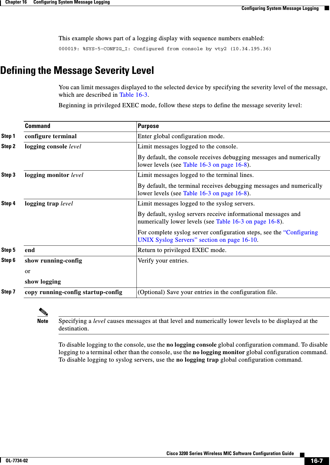
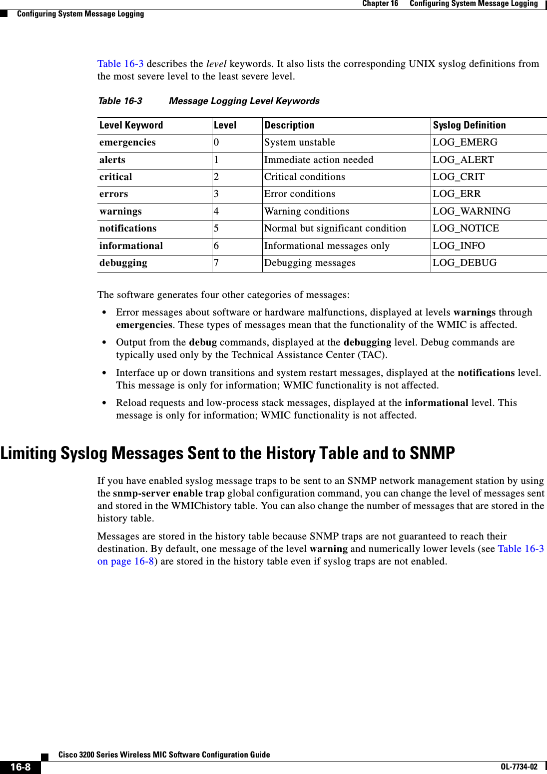
![16-9Cisco 3200 Series Wireless MIC Software Configuration GuideOL-7734-02Chapter 16 Configuring System Message LoggingConfiguring System Message LoggingBeginning in privileged EXEC mode, follow these steps to change the level and history table size defaults:When the history table is full (it contains the maximum number of message entries specified with the logging history size global configuration command), the oldest message entry is deleted from the table to allow the new message entry to be stored.To return the logging of syslog messages to the default level, use the no logging history global configuration command. To return the number of messages in the history table to the default value, use the no logging history size global configuration command.Setting a Logging Rate LimitYou can enable a limit on the number of messages that the device logs per second. You can enable the limit for all messages or for messages sent to the console, and you can specify that messages of a specific severity are exempt from the limit.Beginning in privileged EXEC mode, follow these steps to enable a logging rate limit:To disable the rate limit, use the no logging rate-limit global configuration command.Command PurposeStep 1 configure terminal Enter global configuration mode.Step 2 logging history level11. Table 16-3 lists the level keywords and severity level. For SNMP usage, the severity level values increase by 1. For example, emergenciesequal 1, not 0, and critical equals 3, not 2.Change the default level of syslog messages stored in the history file and sent to the SNMP server.See Table 16-3 on page 16-8 for a list of level keywords.By default, warnings,errors,critical,alerts, and emergencies messages are sent.Step 3 logging history size number Specify the number of syslog messages that can be stored in the history table.The default is to store one message. The range is 1 to 500 messages.Step 4 end Return to privileged EXEC mode.Step 5 show running-config Verify your entries.Step 6 copy running-config startup-config (Optional) Save your entries in the configuration file.Command PurposeStep 1 configure terminal Enter global configuration mode.Step 2 logging rate-limit seconds[all | console][except severity]Enable a logging rate limit in seconds.•(Optional) Apply the limit to all logging or only to messages logged to the console.•(Optional) Exempt a specific severity from the limit.Step 3 end Return to privileged EXEC mode.Step 4 copy running-config startup-config (Optional) Save your entries in the configuration file.](https://usermanual.wiki/Cisco-Systems/XSCLCR14/User-Guide-558354-Page-273.png)
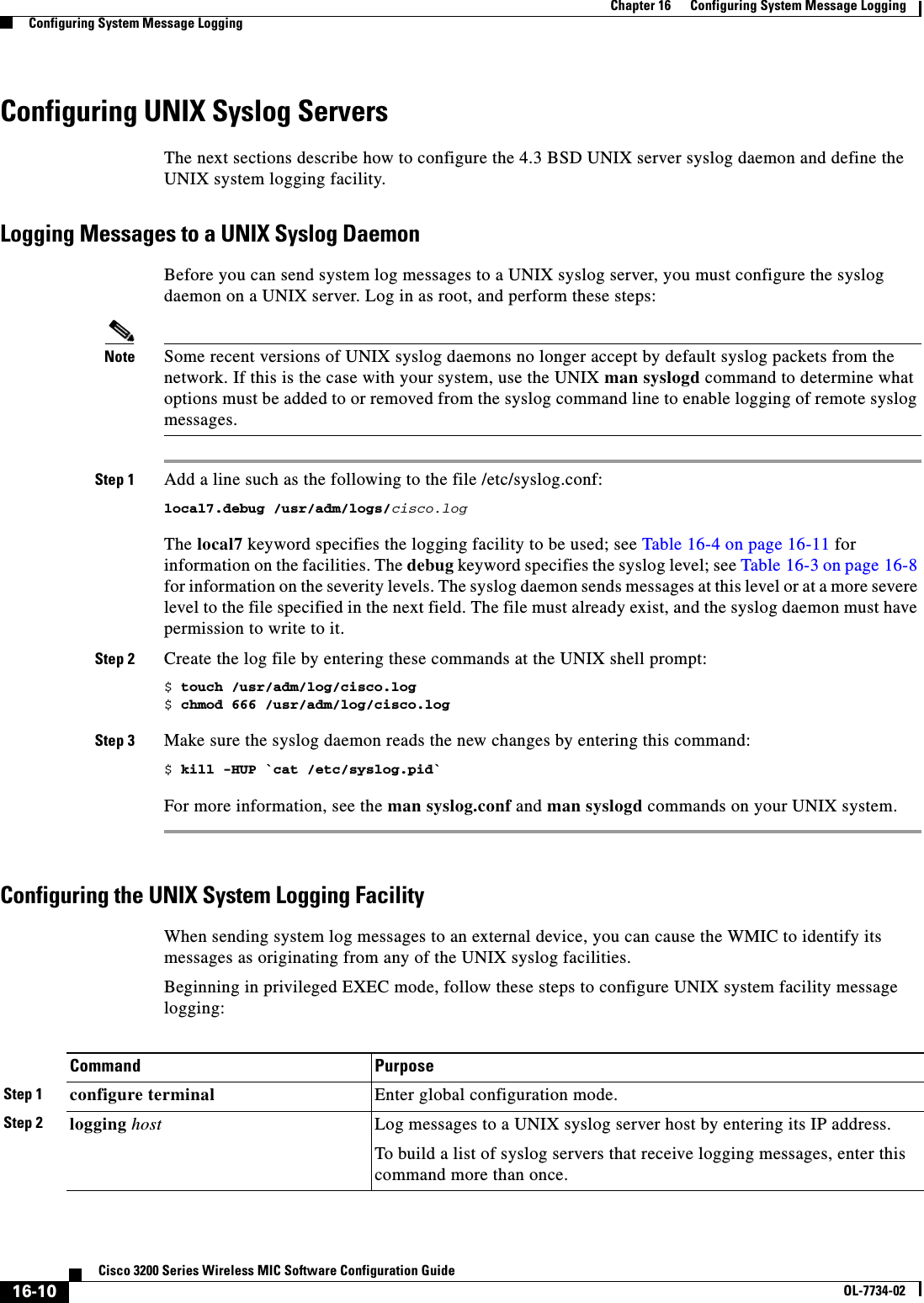
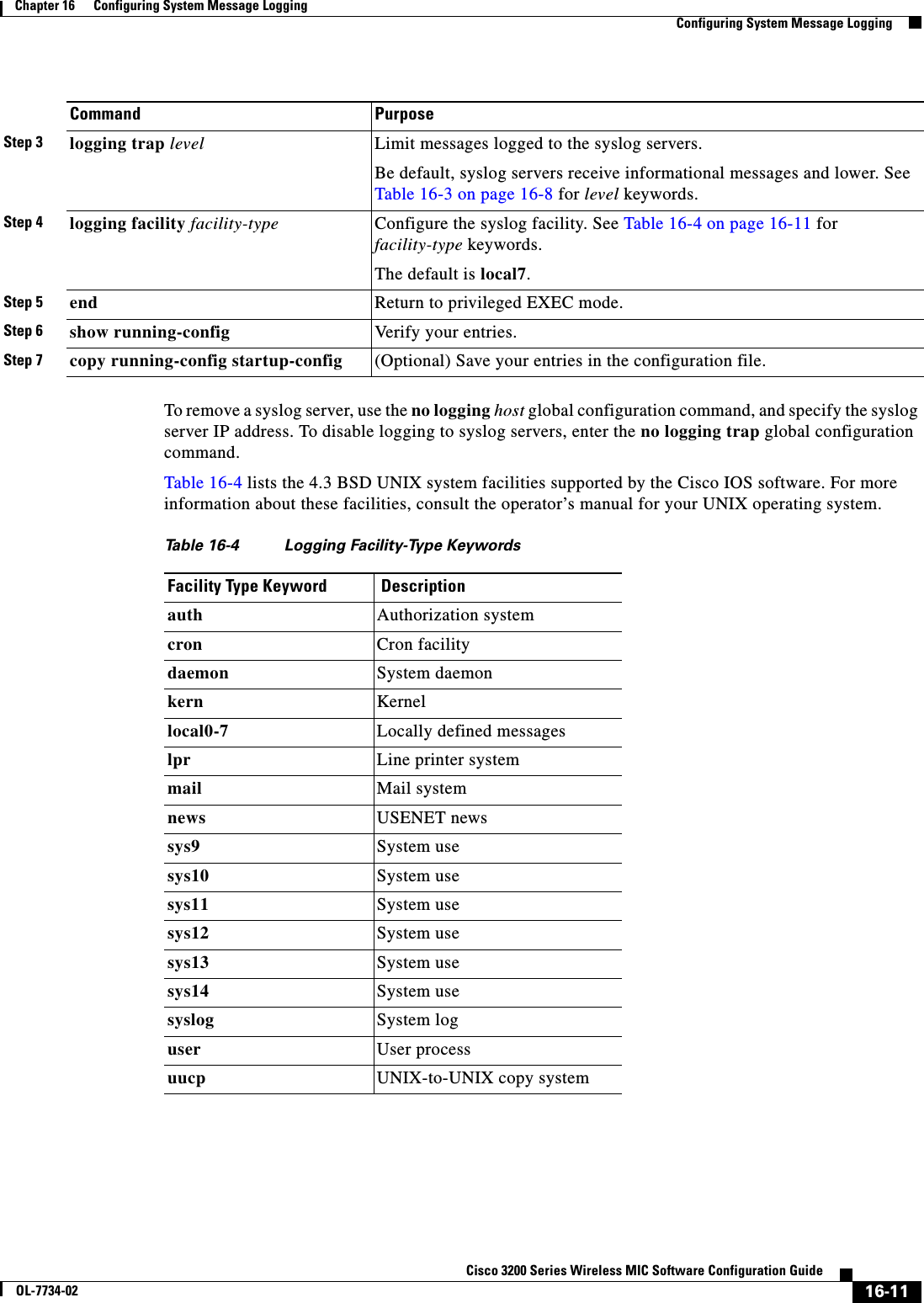
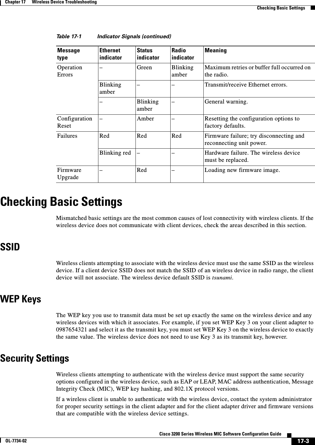
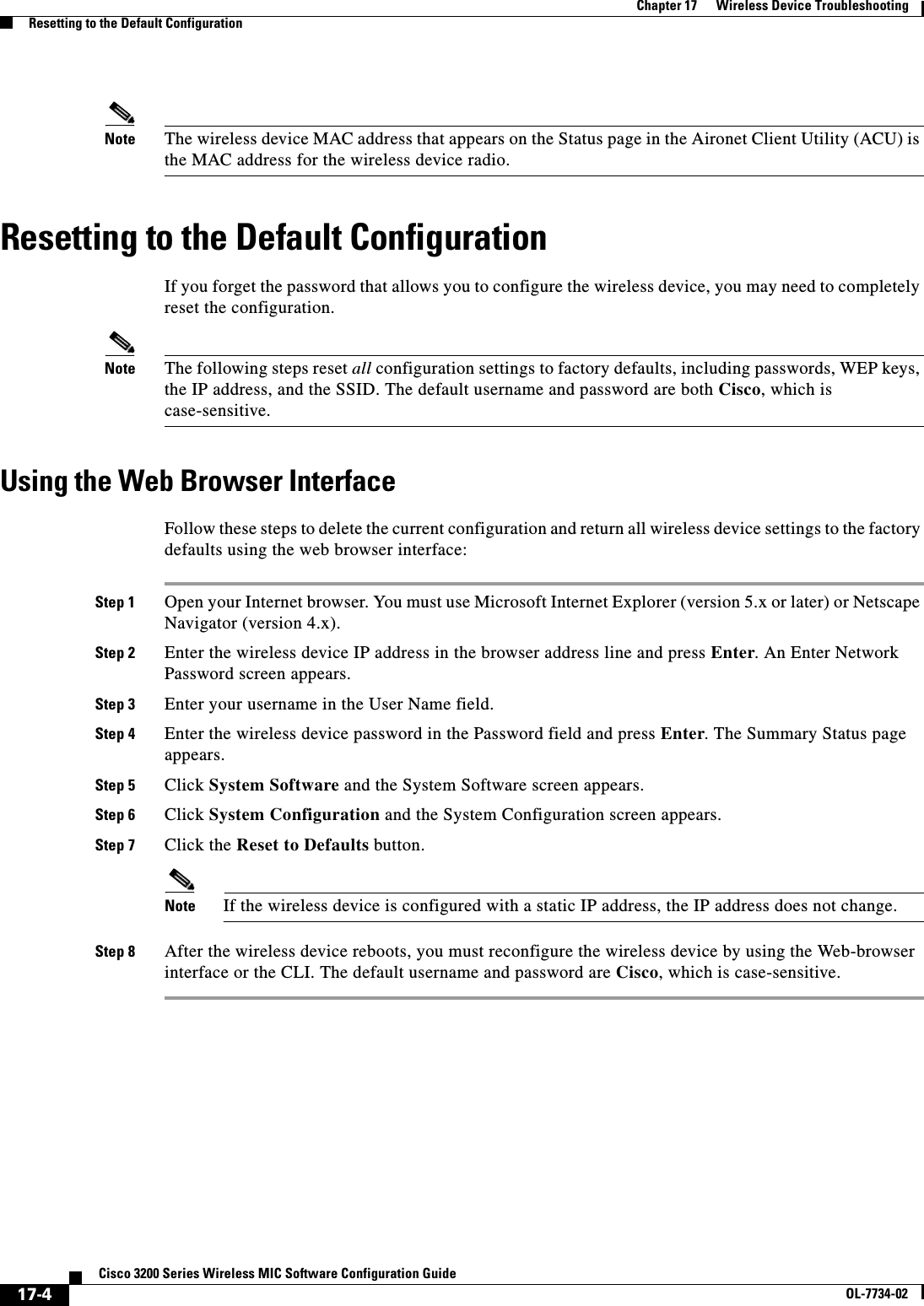
![17-5Cisco 3200 Series Wireless MIC Software Configuration GuideOL-7734-02Chapter 17 Wireless Device TroubleshootingResetting to the Default ConfigurationUsing the CLIFollow the steps below to delete the current configuration and return all wireless device settings to the factory defaults using the CLI.Step 1 Open the CLI using a Telnet session or a connection to the wireless device console port.Step 2 Reboot the wireless device by removing power from and reapplying power to the router.Step 3 Let the wireless device boot until the command prompt appears and the wireless device begins to inflate the image. When you see these lines on the CLI, press Esc:Loading "flash:/c350-k9w7-mx.v122_13_ja.20031010/c350-k9w7-mx.v122_13_ja.20031010"...###############################################################################################################################################################################################################################################################Step 4 At the ap: prompt, enter the flash_init command to initialize the Flash.ap: flash_initInitializing Flash...flashfs[0]: 142 files, 6 directoriesflashfs[0]: 0 orphaned files, 0 orphaned directoriesflashfs[0]: Total bytes: 7612416flashfs[0]: Bytes used: 3407360flashfs[0]: Bytes available: 4205056flashfs[0]: flashfs fsck took 0 seconds....done initializing Flash.Step 5 Use the dir flash: command to display the contents of Flash and find the config.txt configuration file.ap: dir flash:Directory of flash:/3 .rwx 223 <date> env_vars4 .rwx 2190 <date> config.txt5 .rwx 27 <date> private.config150 drwx 320 <date> c350.k9w7.mx.122.13.JA4207616 bytes available (3404800 bytes used)Step 6 Use the rename command to change the name of the config.txt file to config.old.ap: rename flash:config.txt flash:config.oldStep 7 Use the reset command to reboot the wireless device.ap: resetAre you sure you want to reset the system (y/n)?ySystem resetting..Xmodem file system is available.flashfs[0]: 142 files, 6 directoriesflashfs[0]: 0 orphaned files, 0 orphaned directoriesflashfs[0]: Total bytes: 7612416flashfs[0]: Bytes used: 3407360flashfs[0]: Bytes available: 4205056flashfs[0]: flashfs fsck took 0 seconds.Reading cookie from flash parameter block...done.Base ethernet MAC Address: 00:40:96:41:e4:dfLoading "flash:/c350.k9w7.mx.122.13.JA/c350.k9w7.mx.122.13.JA"...######## . . .Note The wireless device is configured with factory default values, including the IP address (set to receive an IP address using DHCP) and the default username and password (Cisco).](https://usermanual.wiki/Cisco-Systems/XSCLCR14/User-Guide-558354-Page-281.png)
![17-6Cisco 3200 Series Wireless MIC Software Configuration GuideOL-7734-02Chapter 17 Wireless Device TroubleshootingReloading the ImageStep 8 When IOS software is loaded, you can use the del privileged EXEC command to delete the config.old file from Flash. ap# del flash:config.oldDelete filename [config.old]Delete flash:config.old [confirm]ap#Reloading the ImageIf the wireless device has a firmware failure, you must reload the image file using the Web browser interface. You can use the browser interface if the wireless device firmware is still fully operational and you want to upgrade the firmware image.If the wireless device experiences a firmware failure or a corrupt firmware image, indicated by three red LED indicators, you must reload the image from a connected TFTP server.Note This process resets all configuration settings to factory defaults, including passwords, WEP keys, the wireless device IP address, and SSIDs. Using the Web Browser InterfaceYou can also use the Web browser interface to reload the wireless device image file. The Web broswer interface supports loading the image file using HTTP or TFTP interfaces. Note Your wireless device configuration does not change when you use the browser to reload the image file.Browser HTTP InterfaceThe HTTP interface enables you to browse to the wireless device image file on your PC and download the image to the wireless device. Follow the instructions below to use the HTTP interface:Step 1 Open your Internet browser. You must use Microsoft Internet Explorer (version 5.x or later) or Netscape Navigator (version 4.x).Step 2 Enter the wireless device IP address in the browser address line and press Enter. An Enter Network Password screen appears.Step 3 Enter your username in the User Name field.Step 4 Enter the wireless device password in the Password field and press Enter. The Summary Status page appears.Step 5 Click the System Software tab and then click Software Upgrade. The HTTP Upgrade screen appears.Step 6 Click Browse to find the image file on your PC.](https://usermanual.wiki/Cisco-Systems/XSCLCR14/User-Guide-558354-Page-282.png)
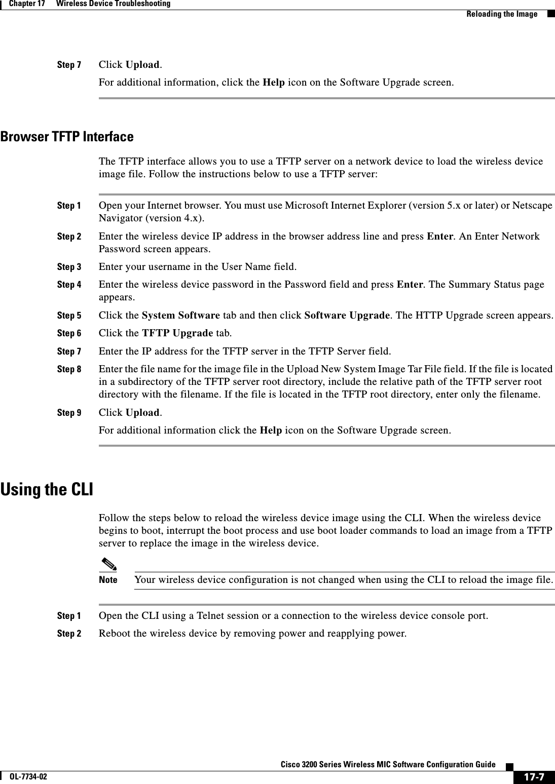
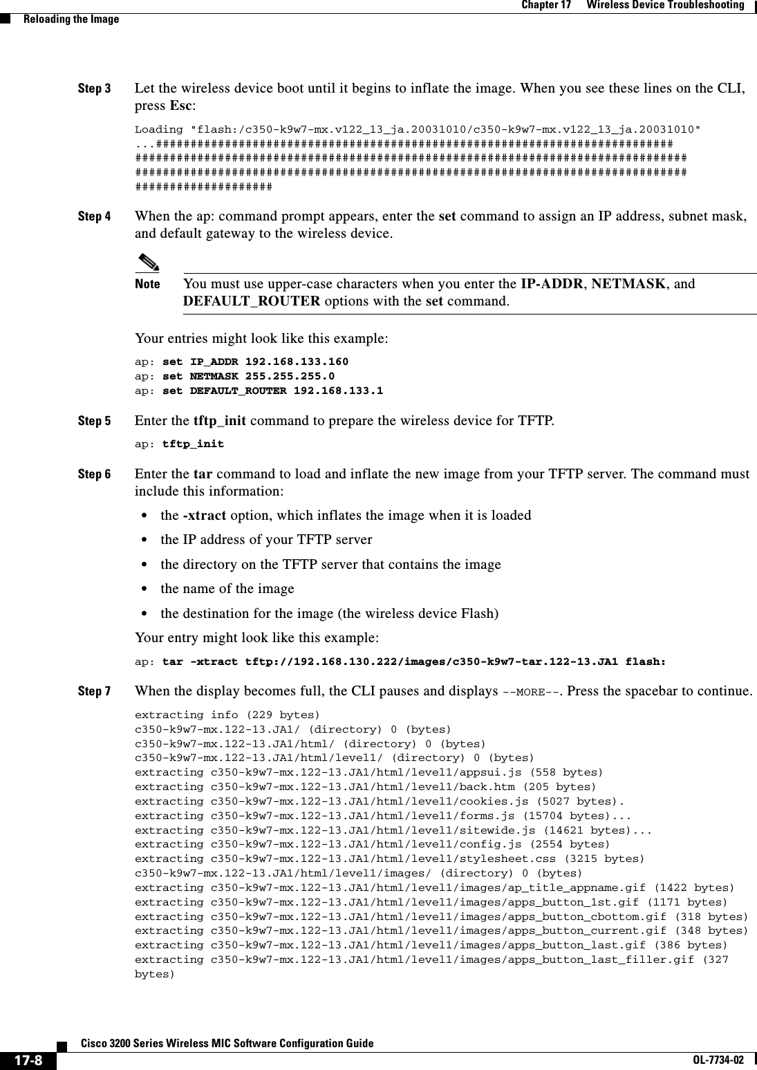
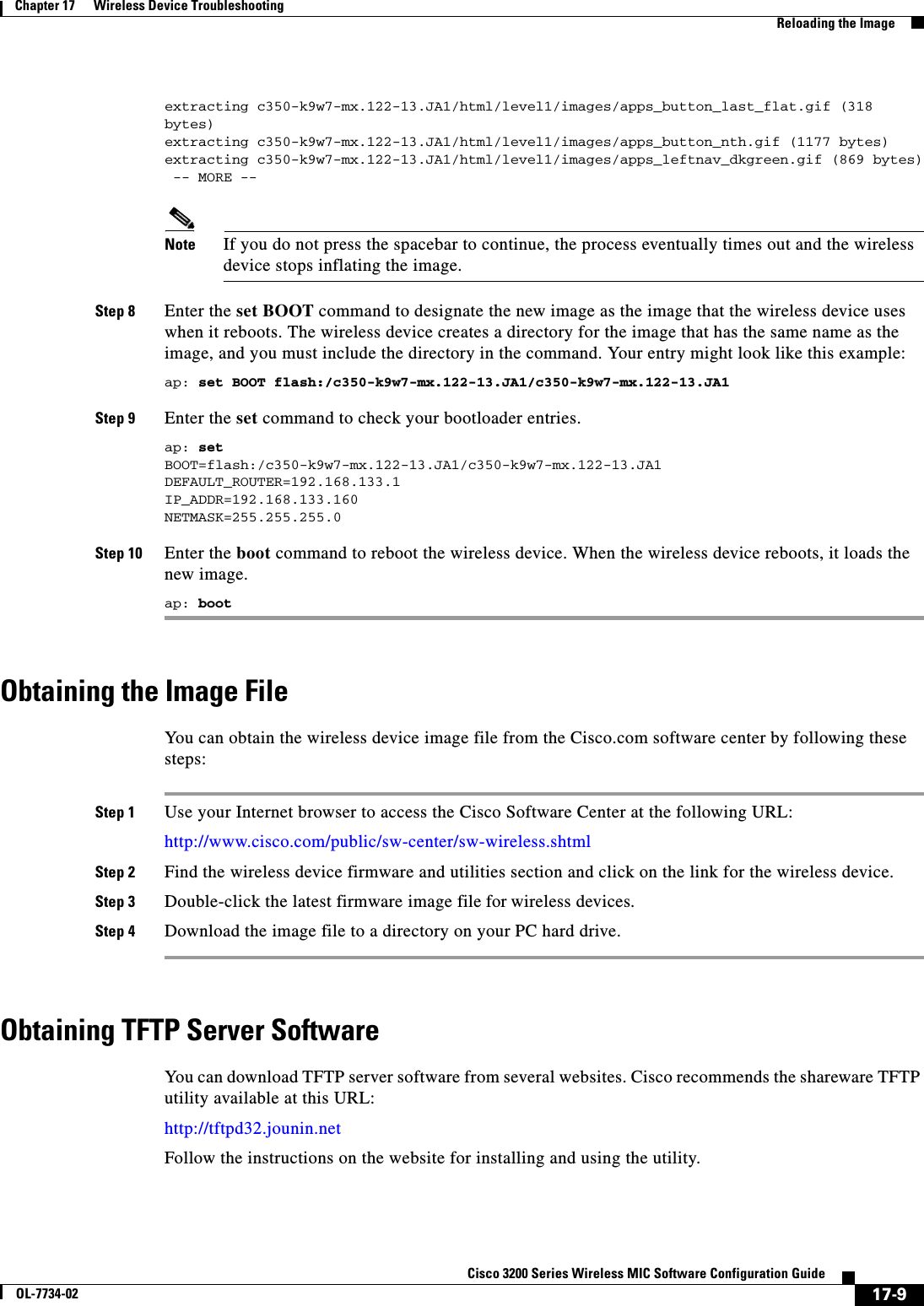
![17-10Cisco 3200 Series Wireless MIC Software Configuration GuideOL-7734-02Chapter 17 Wireless Device TroubleshootingReloading the Bootloader ImageReloading the Bootloader ImageFollow this procedure to download the boot loader image to the device:Step 1 Place the bootloader image in the proper directory on a TFTP server.Step 2 Connect to the console. Step 3 Enter the enable command to enter privileged mode.Step 4 Download the new boot loader image from the TFTP server to the boot sector by using the copy tftp://ip address/path/imagename bs: command, where ip address is the address of the TFTP server and path is the path to the directory where the boot loader image is located.Caution The boot sector Flash file system is addressed as bs:. The WMIC will not boot up and will not recover if a non-bootloader image is downloaded to the boot sector of the Flash file system. Step 5 When the boot loader download is complete, enter the reset command at the console prompt to reset the device.Step 6 When the boot loader upgrade is complete, enter the boot command at the console prompt to reboot the device.Step 7 Enter the version commmand to verify that it boots using the upgraded boot loader.Example Command Outputbridge: copy tftp://223.255.254.253/tftpboot/jrehage/loader_c3202_bs.img bs:................................................................File "tftp://223.255.254.253/tftpboot/jrehage/loader_c3202_bs.img" successfully copied to "bs:"bridge:resetAre you sure you want to reset the system (y/n)?ySystem resetting... Xmodem file system is available.flashfs[0]:136 files, 6 directoriesflashfs[0]:0 orphaned files, 0 orphaned directoriesflashfs[0]:Total bytes:15998976flashfs[0]:Bytes used:7458304flashfs[0]:Bytes available:8540672flashfs[0]:flashfs fsck took 30 seconds.Base ethernet MAC Address:00:ff:ff:f0:01:4fInitializing ethernet port 0...Reset ethernet port 0...Reset done!ethernet link up, 100 mbps, full-duplexEthernet port 0 initialized:link is up](https://usermanual.wiki/Cisco-Systems/XSCLCR14/User-Guide-558354-Page-286.png)
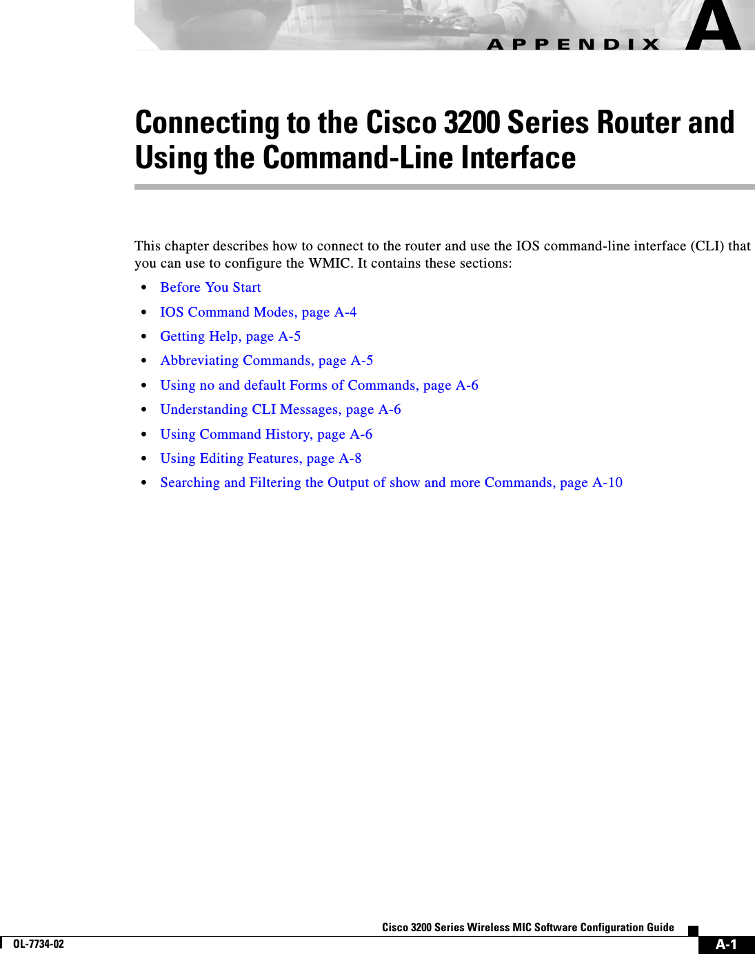
![A-2Cisco 3200 Series Wireless MIC Software Configuration GuideOL-7734-02Appendix A Connecting to the Cisco 3200 Series Router and Using the Command-Line Interface Before You StartBefore You StartBefore you install the WMIC, make sure you are using a computer connected to the same network as the WMIC, and obtain the following information from your network administrator:•A system name for the WMIC•The case-sensitive wireless service set identifier (SSID) that your WMICs use•If not connected to a DHCP server, a unique IP address for your WMIC (such as 172.17.255.115)•If the WMIC is not on the same subnet as your PC, a default gateway address and subnet mask•A Simple Network Management Protocol (SNMP) community name and the SNMP file attribute (if SNMP is in use)Resetting the WMIC to the Default SettingsYou can use the CLI to reset the WMIC to a factory default configuration.Note The following steps reset all configuration settings to factory defaults, including passwords, WEP keys, the IP address, and the SSID. From the privileged EXEC mode, you can reset the WMIC configuration to factory default values using the CLI by following these steps: Step 1 Enter erase nvram: to erase all NVRAM files including the startup configuration.Step 2 Enter Y when the following CLI message displays: Erasing the nvram filesystem will remove all configuration files! Continue? [confirm].Step 3 Enter reload when the following CLI message displays: Erase of nvram: complete. This command reloads the operating system.Step 4 Enter Y when the following CLI message displays: Proceed with reload? [confirm].Caution Do not interrupt the boot process to avoid damaging the configuration file. You can see the following CLI message when the load process has finished: Line protocal on Interface Dot11Radio0, changed state to up.Step 5 After the WMIC reboots, you can reconfigure the WMIC by using the Web-browser interface or the CLI.To obtain the WMIC’s new IP address, you can use the show interface bvi1 CLI command.](https://usermanual.wiki/Cisco-Systems/XSCLCR14/User-Guide-558354-Page-288.png)
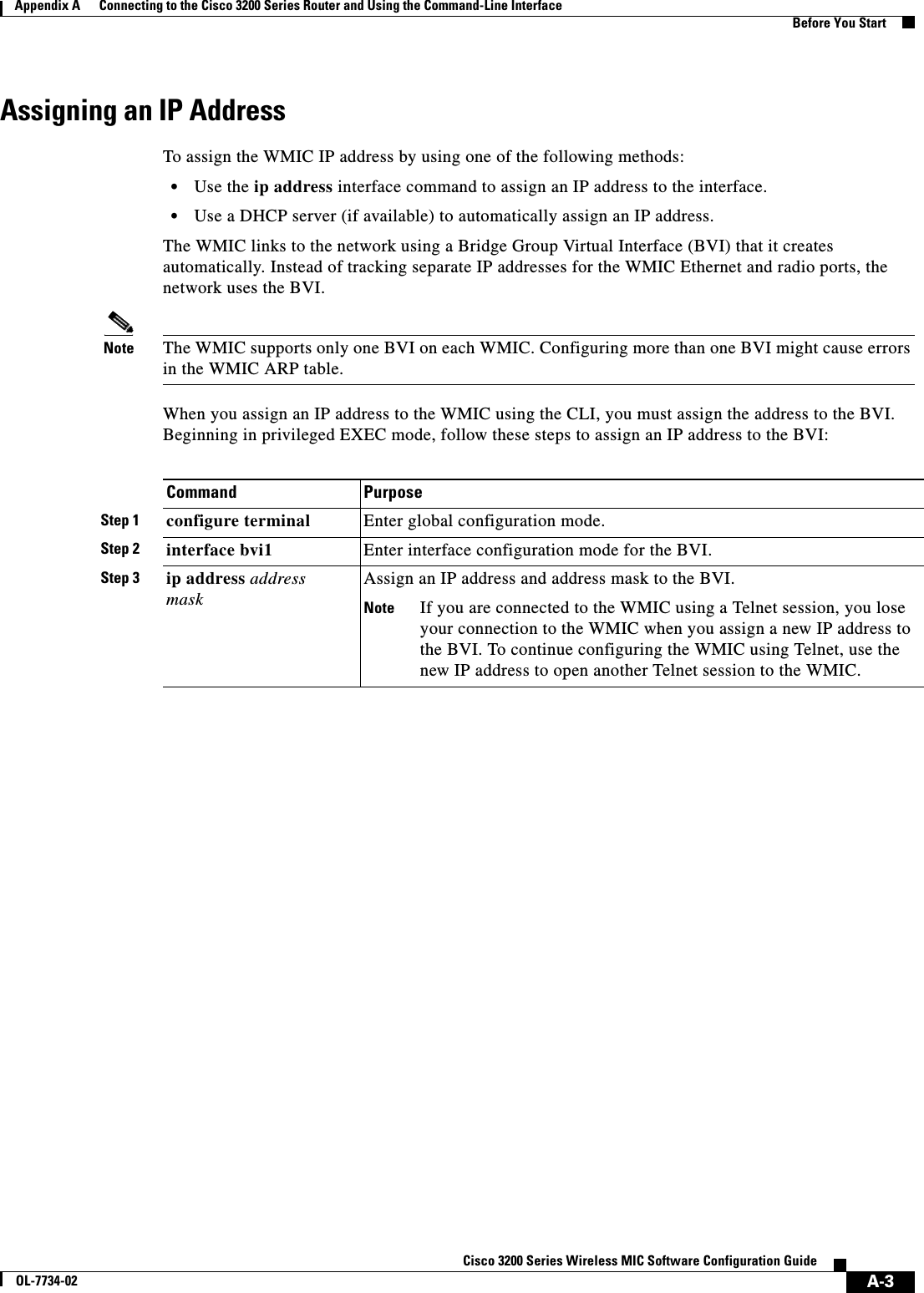
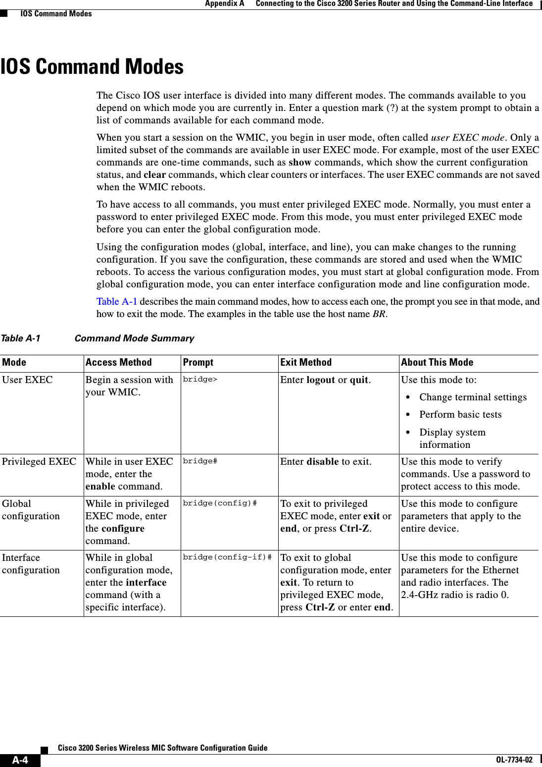
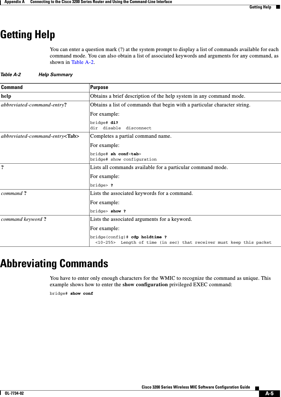
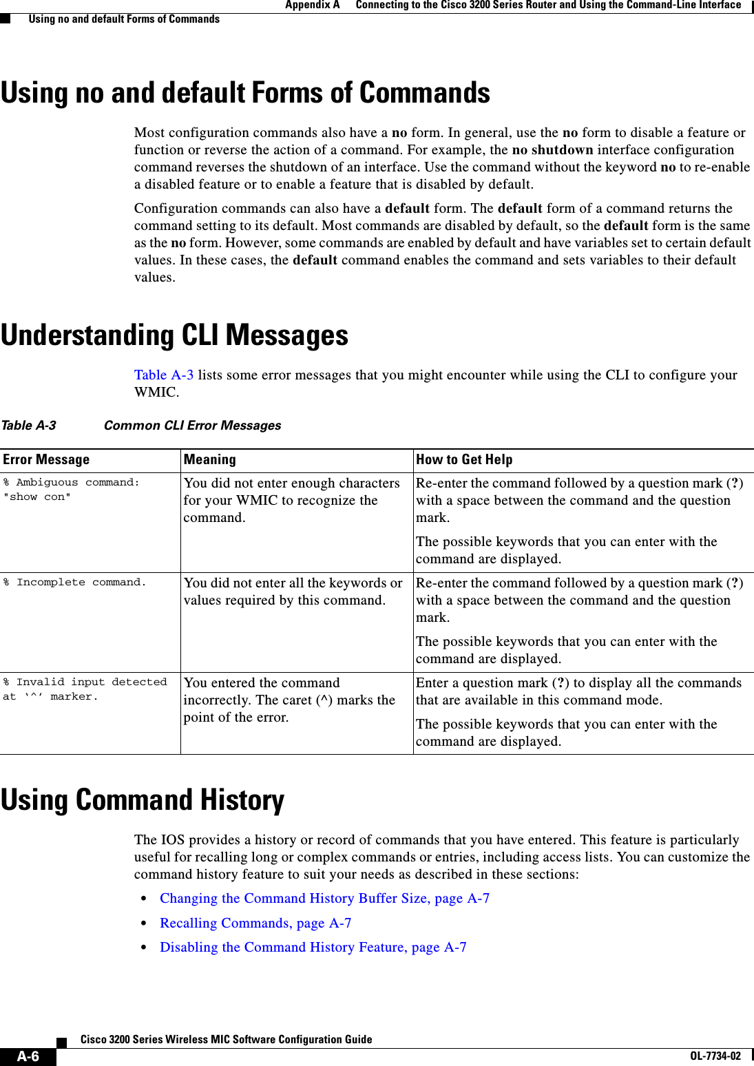
![A-7Cisco 3200 Series Wireless MIC Software Configuration GuideOL-7734-02Appendix A Connecting to the Cisco 3200 Series Router and Using the Command-Line Interface Using Command HistoryChanging the Command History Buffer SizeBy default, the WMIC records ten command lines in its history buffer. Beginning in privileged EXEC mode, enter this command to change the number of command lines that the WMIC records during the current terminal session: bridge# terminal history [size number-of-lines]The range is from 0 to 256.Beginning in line configuration mode, enter this command to configure the number of command lines the WMIC records for all sessions on a particular line:bridge(config-line)# history [size number-of-lines]The range is from 0 to 256.Recalling CommandsTo recall commands from the history buffer, perform one of the actions listed in Table A-4:Disabling the Command History FeatureThe command history feature is automatically enabled. To disable the feature during the current terminal session, enter the terminal no history privileged EXEC command. To disable command history for the line, enter the no history line configuration command.Table A-4 Recalling CommandsAction11. The arrow keys function only on ANSI-compatible terminals such as VT100s.ResultPress Ctrl-P or the up arrow key. Recall commands in the history buffer, beginning with the most recent command. Repeat the key sequence to recall successively older commands.Press Ctrl-N or the down arrow key. Return to more recent commands in the history buffer after recalling commands with Ctrl-P or the up arrow key. Repeat the key sequence to recall successively more recent commands. show history While in privileged EXEC mode, list the last several commands that you just entered. The number of commands that are displayed is determined by the setting of the terminal history global configuration command and history line configuration command.](https://usermanual.wiki/Cisco-Systems/XSCLCR14/User-Guide-558354-Page-293.png)
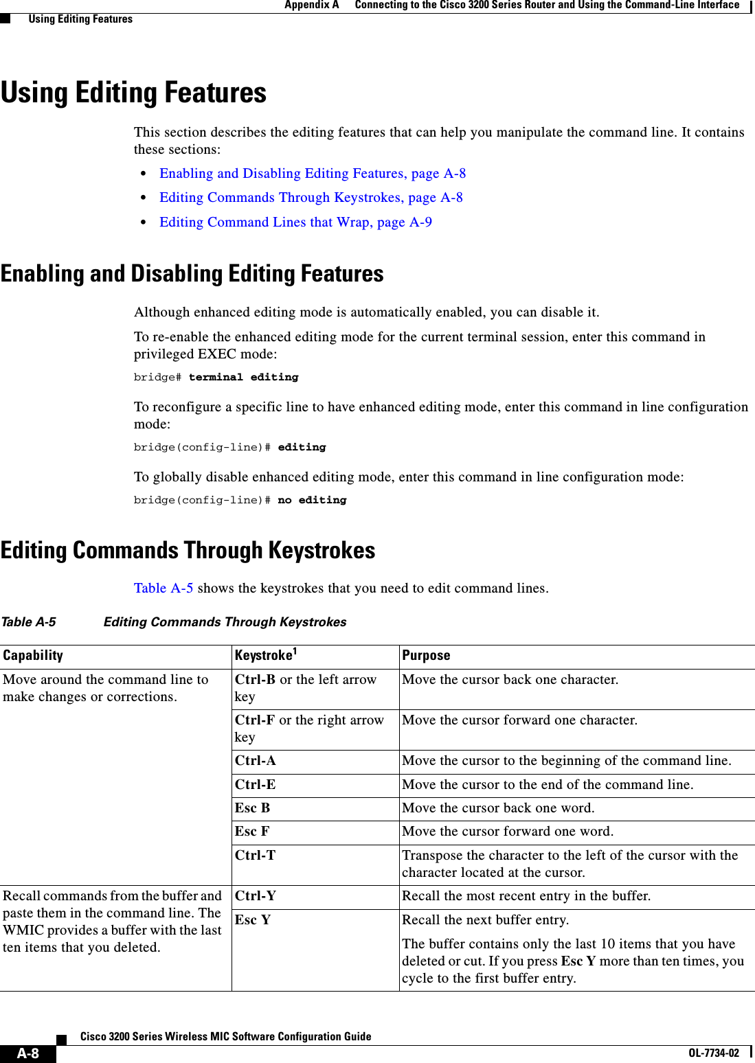
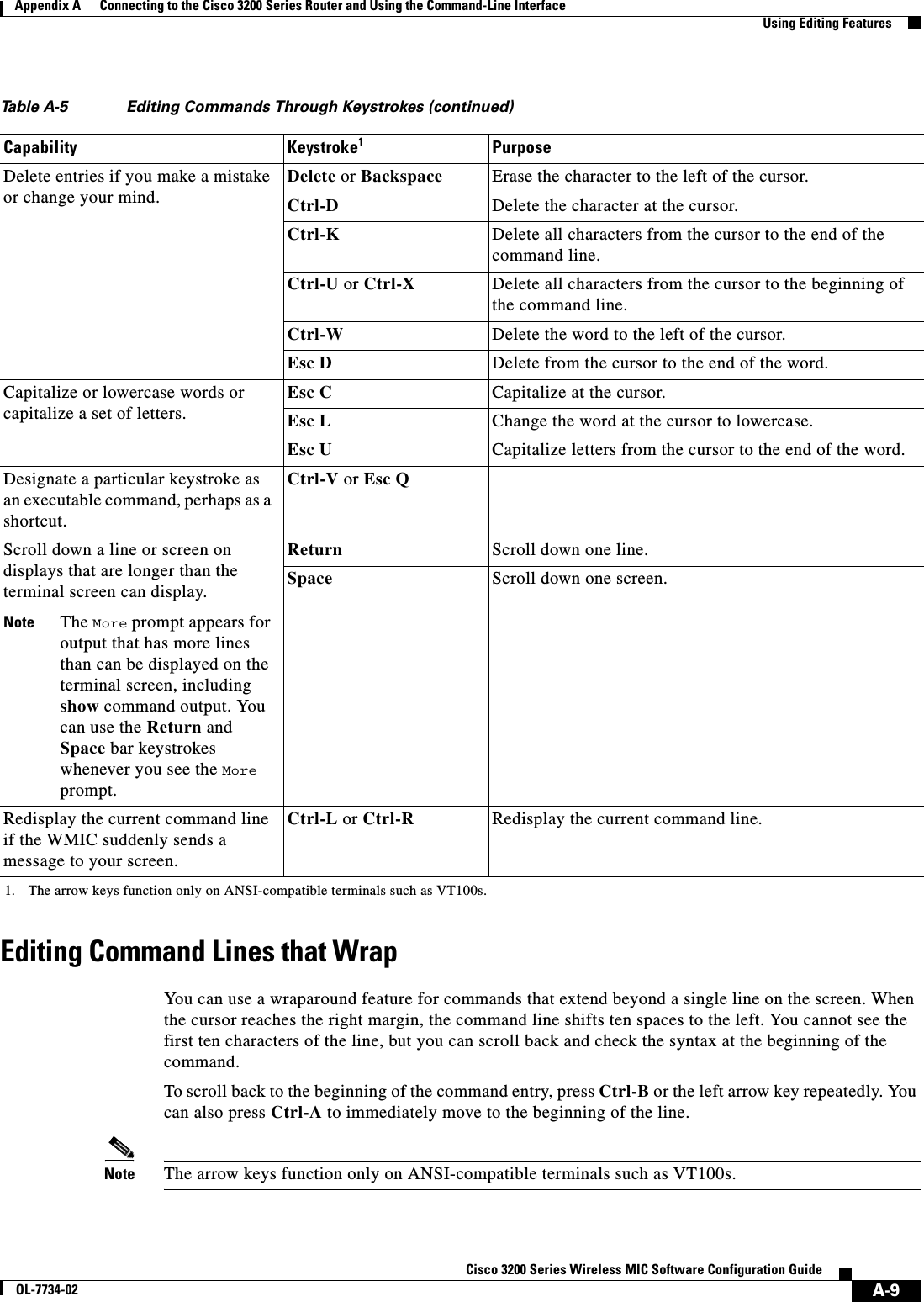
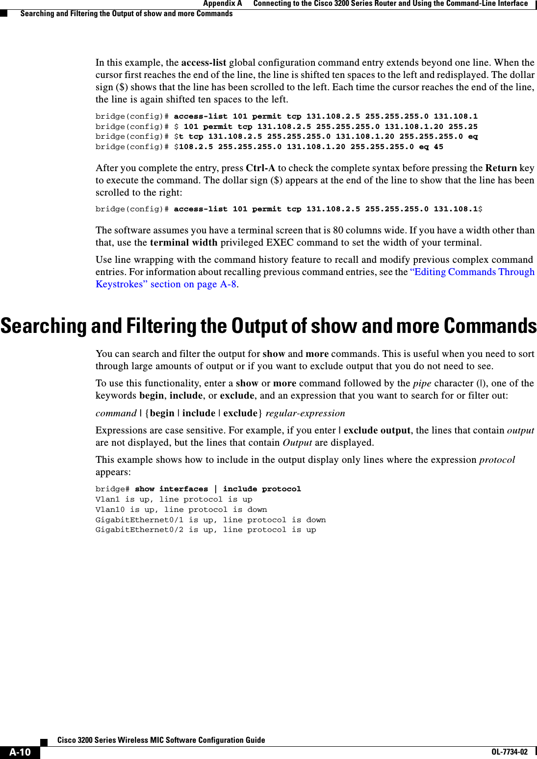

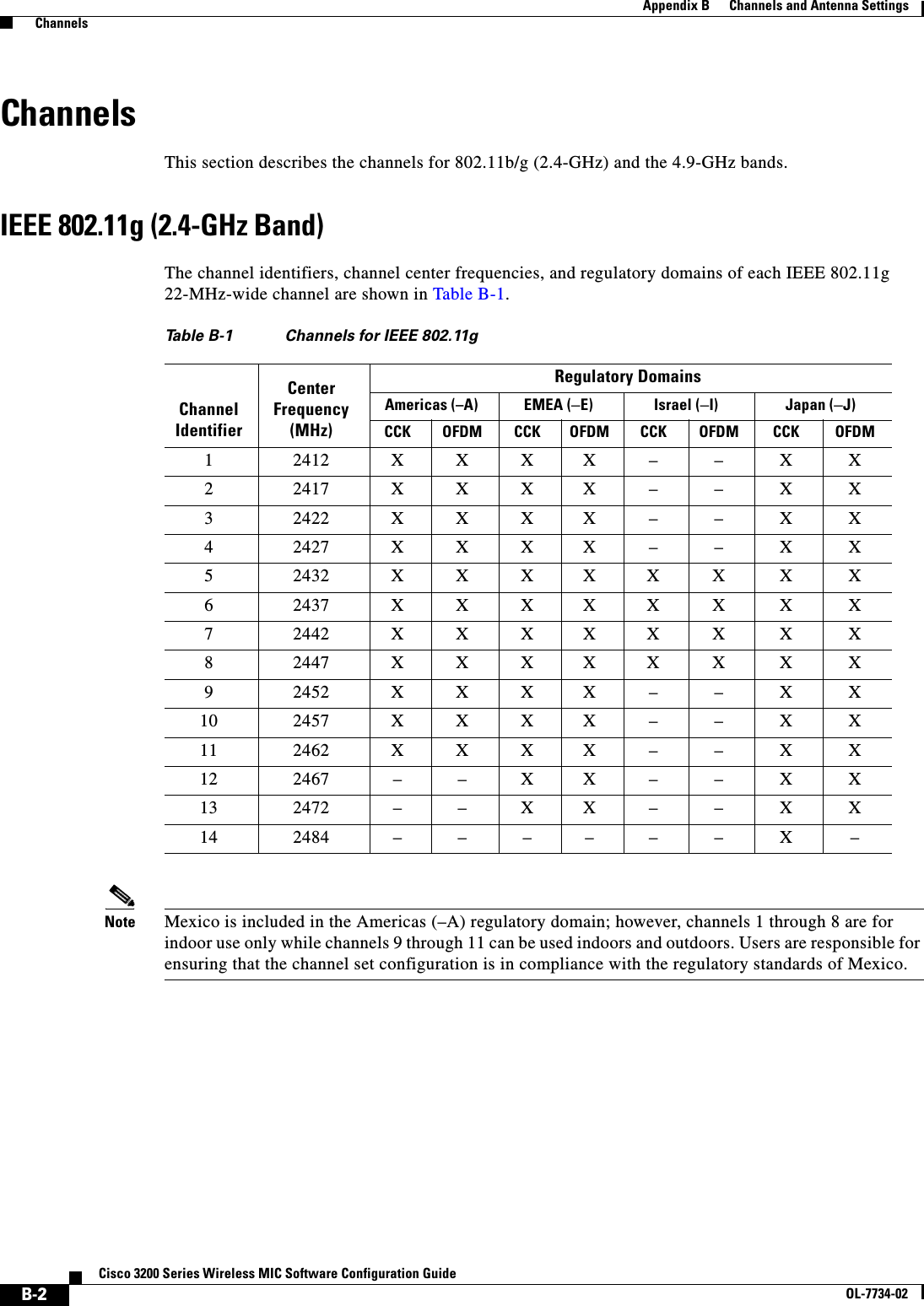
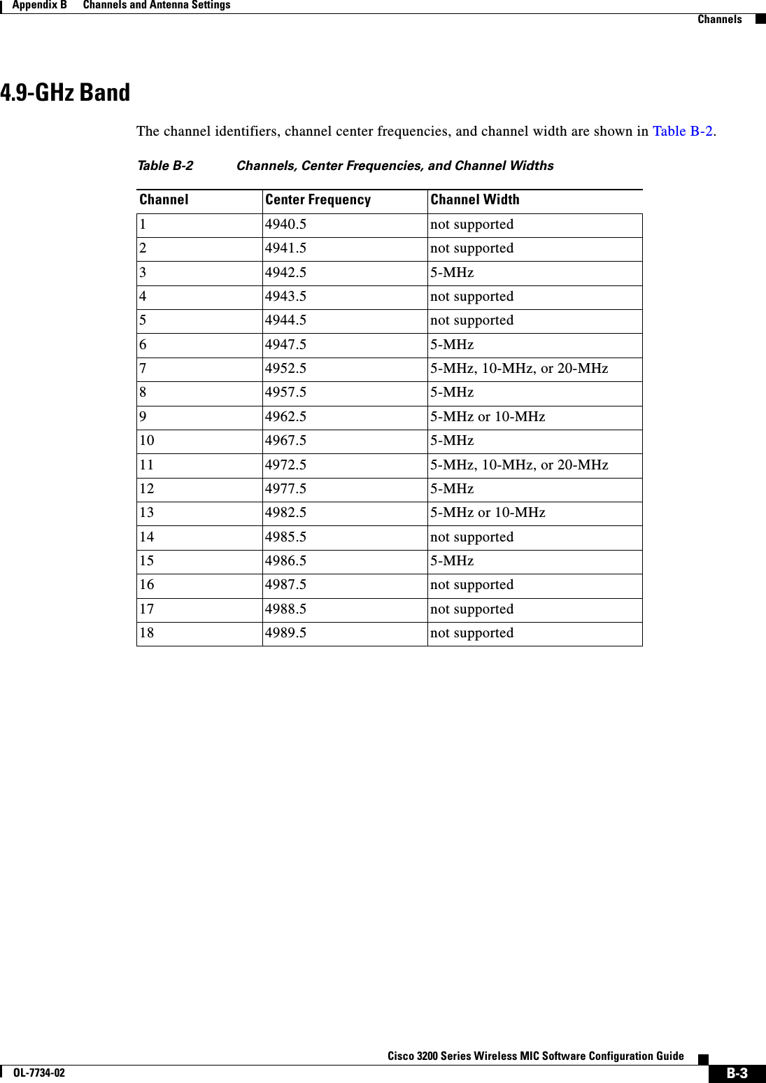
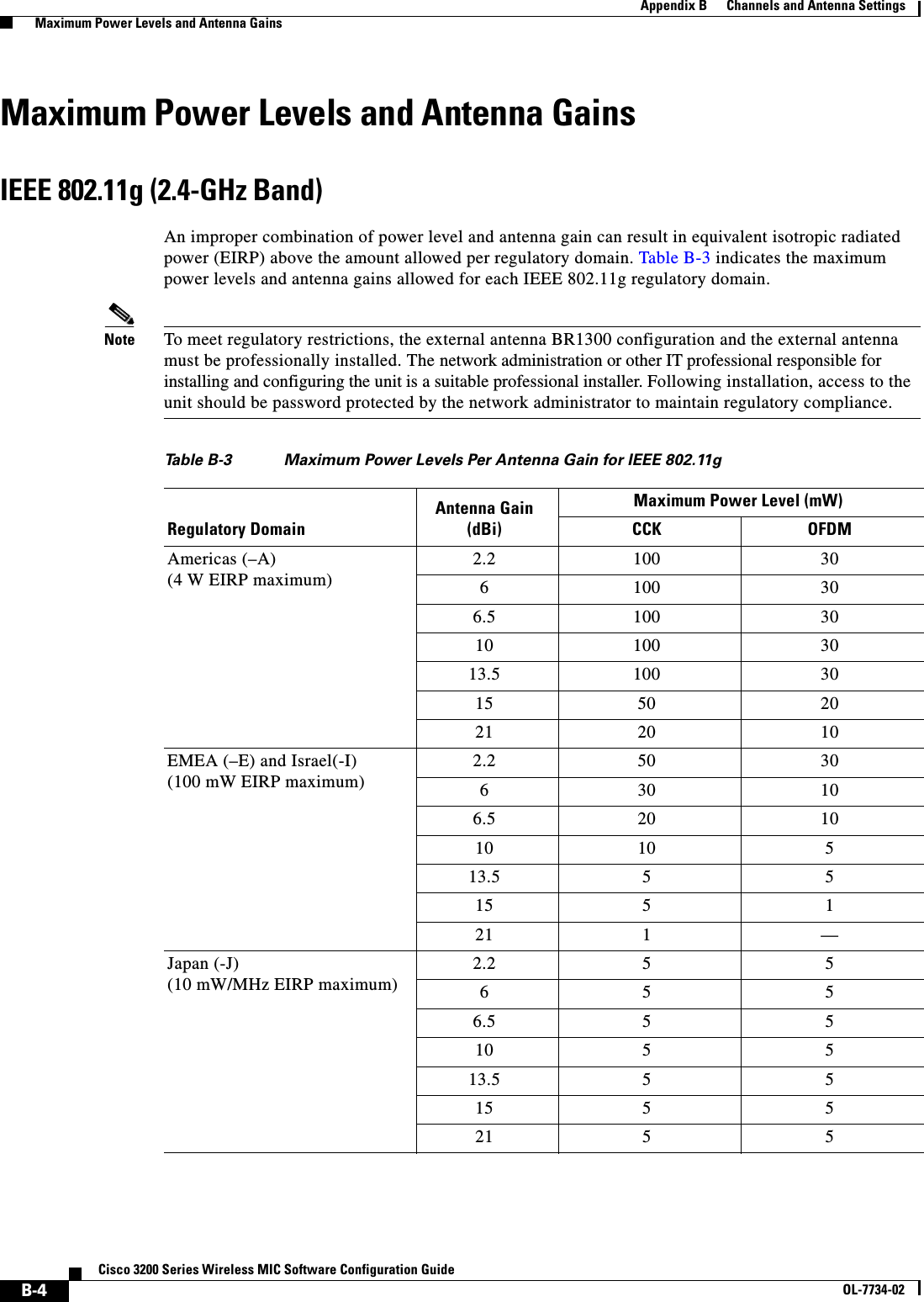

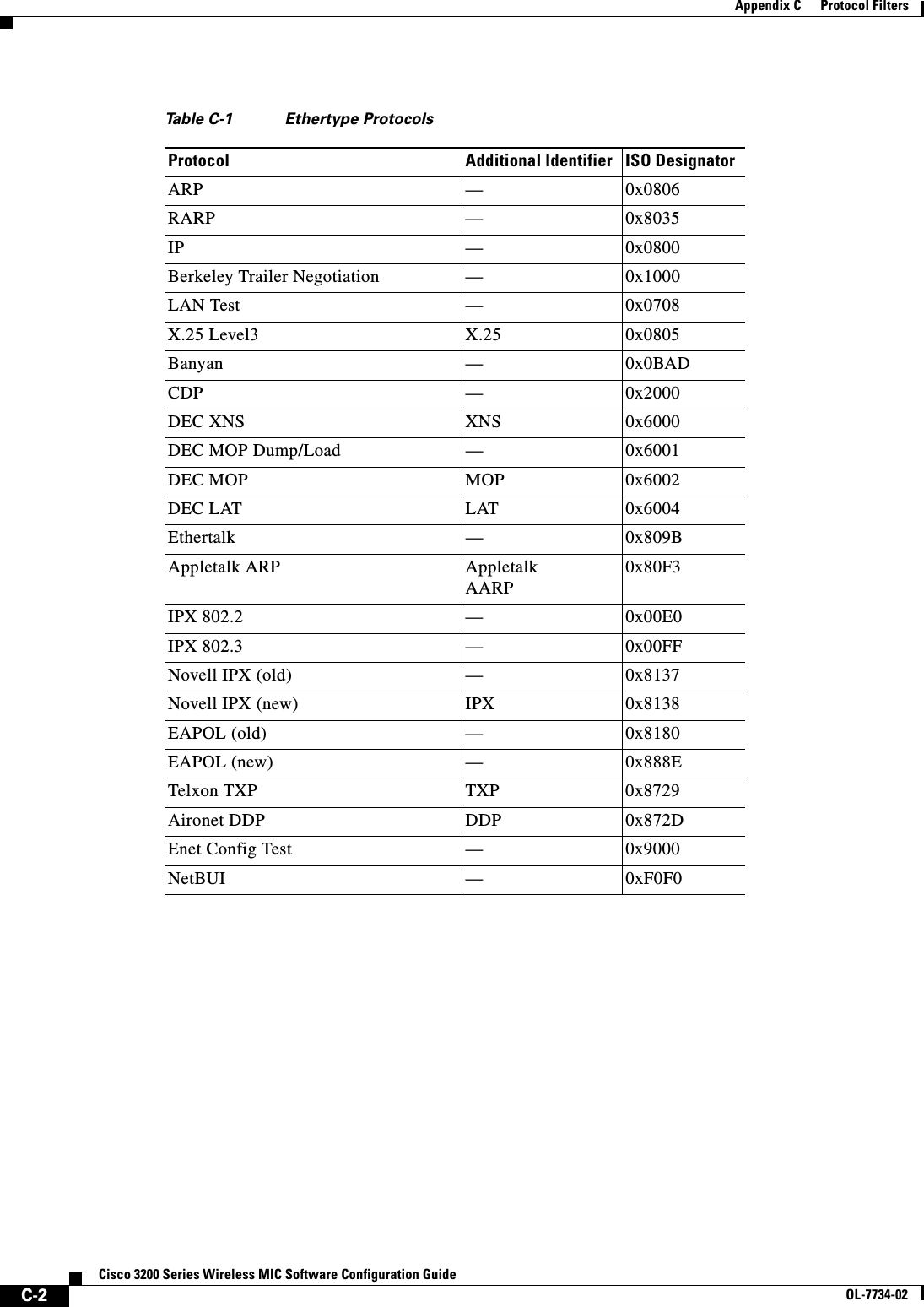
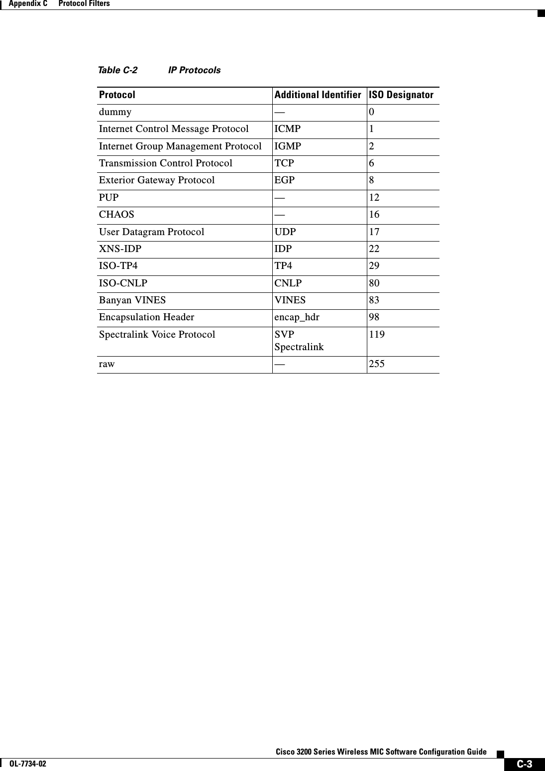
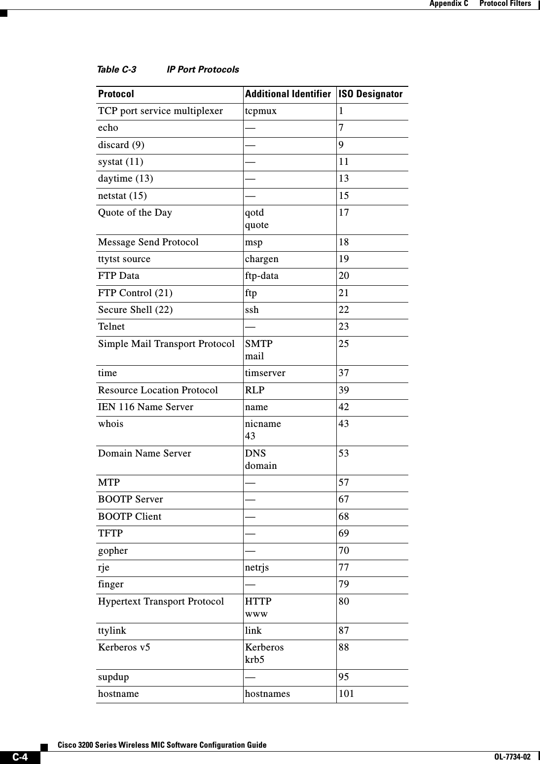
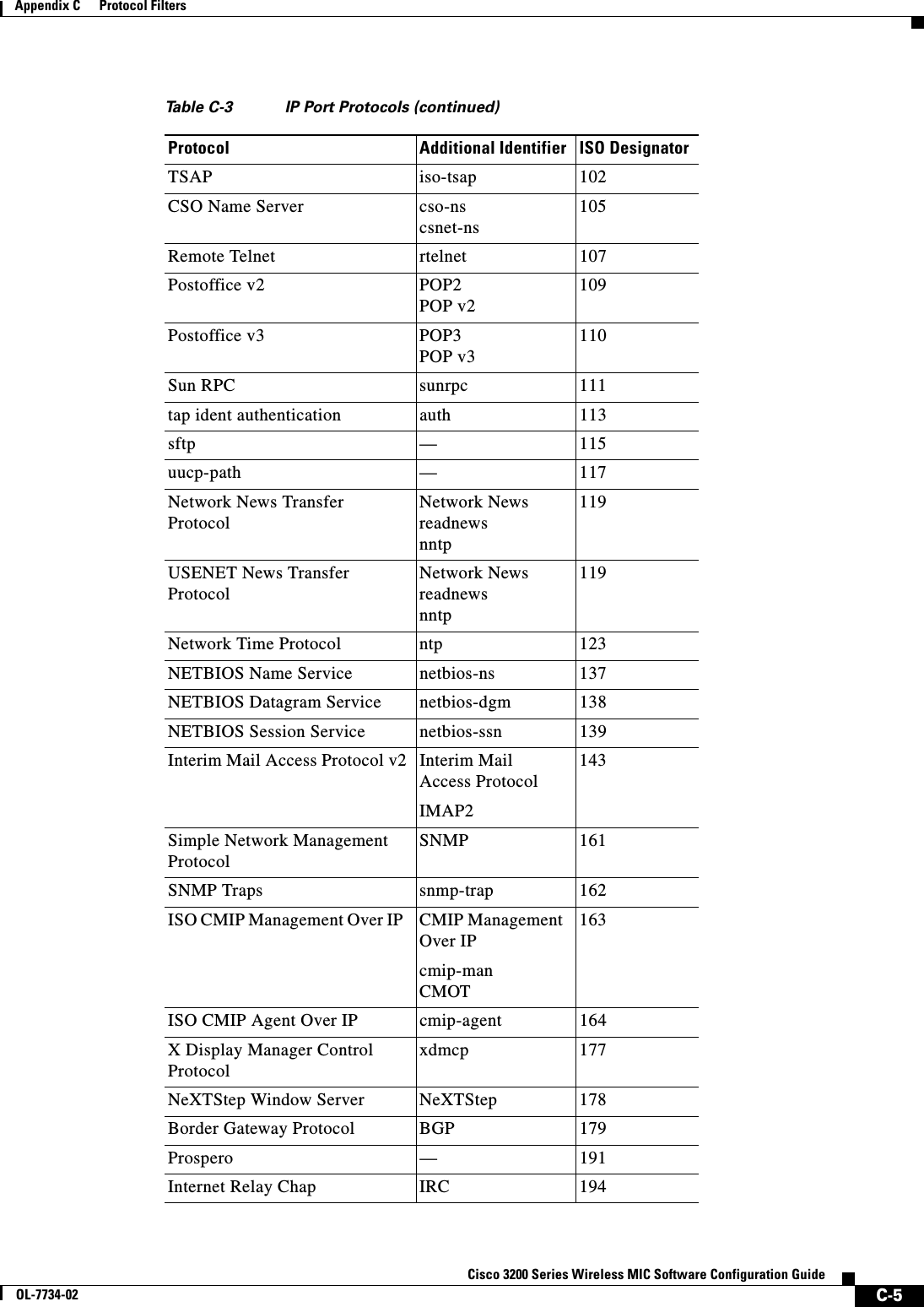
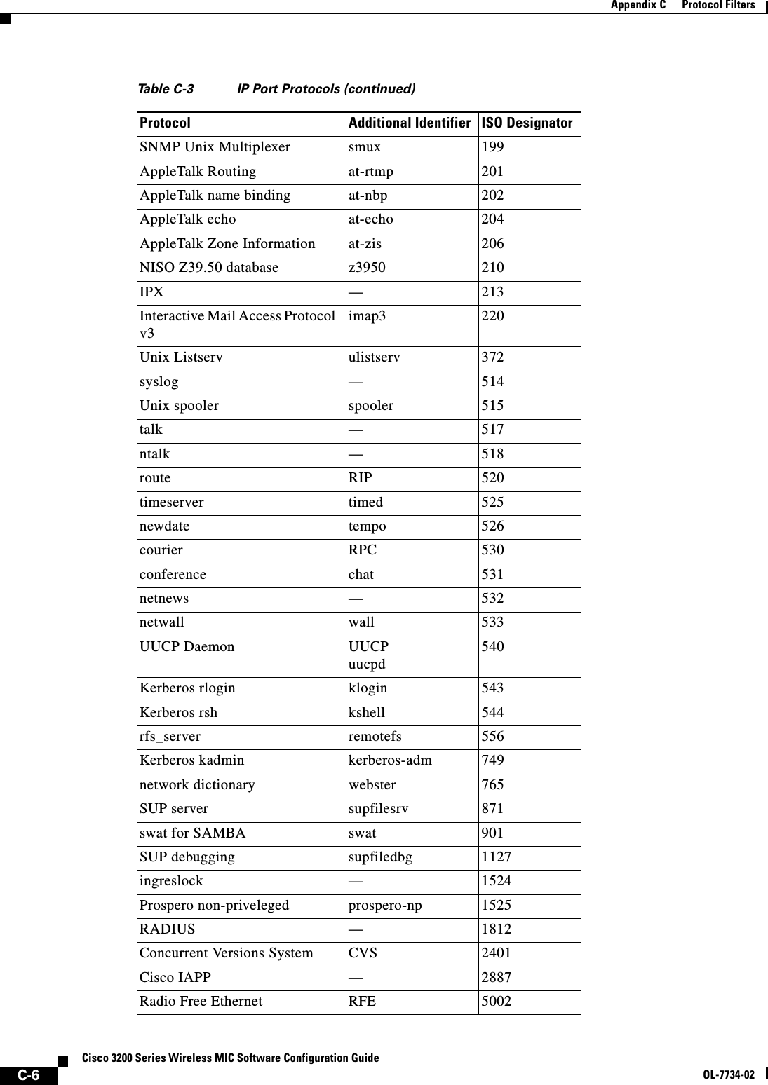
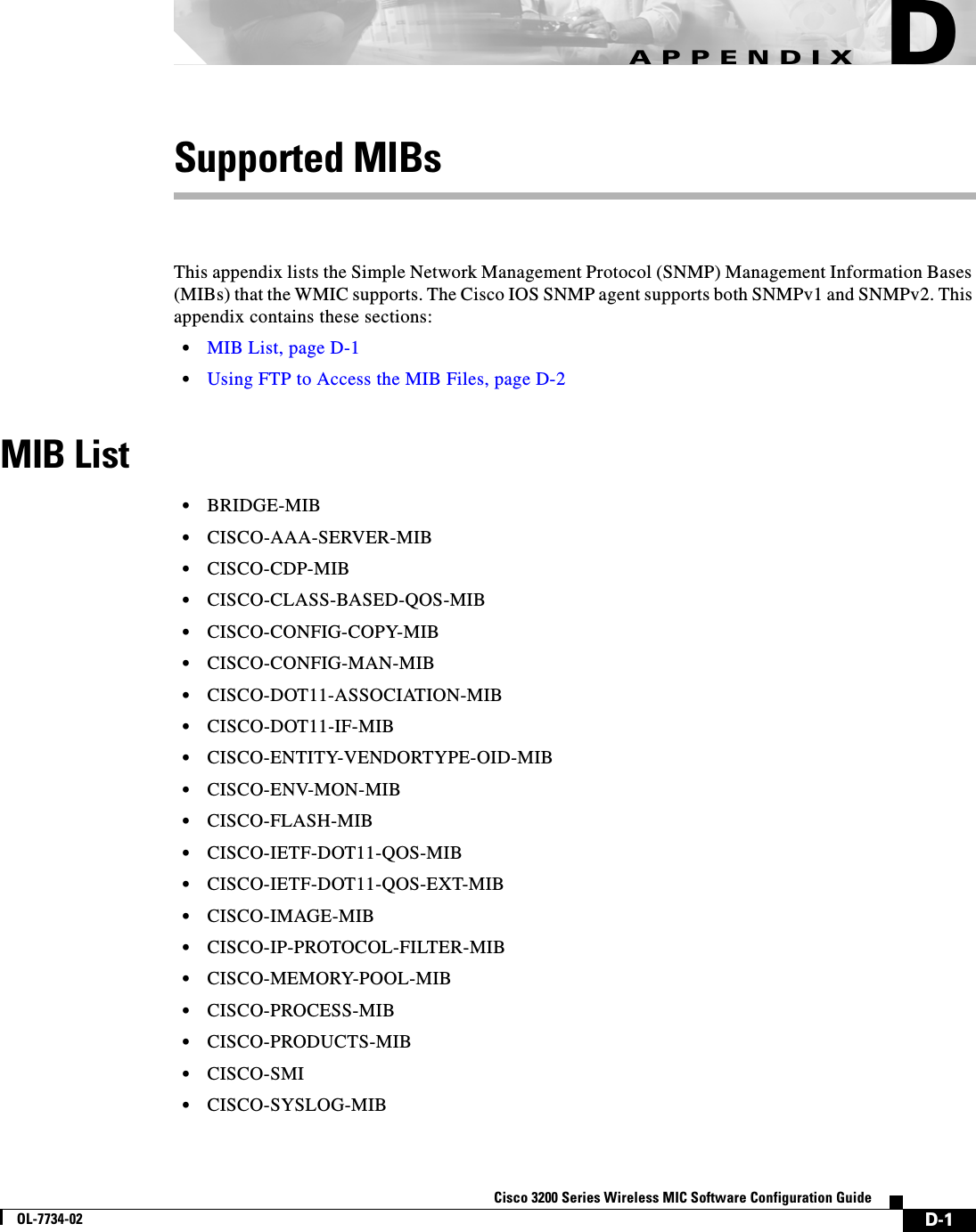
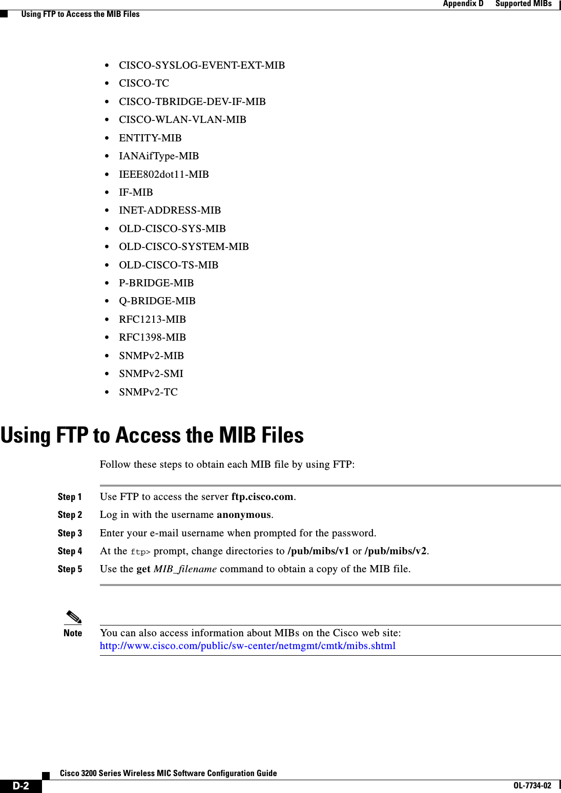
![E-1Cisco 3200 Series Wireless MIC Software Configuration GuideOL-7734-02APPENDIXEError and Event MessagesThis appendix lists the CLI error and event messages. Table E-1 lists the errors and events and provides an explanation and recommended action for each message.Table E-1 Error and Event MessagesMessage Explanation Recommended ActionSoftware Auto Upgrade MessagesSW_AUTO_UPGRADE-FATAL: Attempt to upgrade software failed, software on Flash may be deleted. Please copy software into Flash. Auto upgrade of the software failed. The software on the Flash memory might have been deleted. Copy software into the Flash memory. Copy software before rebooting the unit. SW_AUTO_UPGRADE-7-FAILURE: dhcp_client_start_stop failed Auto upgrade of the software failed due to error in starting/stopping DHCP client process.Copy the error message exactly as it appears and report it to your technical support representative. SW_AUTO_UPGRADE-7-FAILURE: Failed to obtain ip addr from dhcp server Auto upgrade of the software failed. Copy the error message exactly as it appears and report it to your technical support representative.SW_AUTO_UPGRADE-7-FAILURE: boot_file_pathent creation failed Auto upgrade of the software failed due to error in creation of pathent (internal data structure).Copy the error message exactly as it appears and report it to your technical support representative.Association Management MessagesDOT11-2-RADIO_HW_RESET: Radio subsystem is under going hardware reset to recover from problemRadio must be reset due to problem. None.DOT11-3-BADSTATE: [mac-address] [chars] [chars] -> [chars]802.11 Association and management uses a table-driven state machine to keep track and transition an Association through various states. A state transition occurs when an Association receives one of many possible events. When this error occurs, it means that an Association received an event that it did not expect while in this state.The system can continue but may lose the Association that generates this error. Copy the message exactly as it appears and report it to your technical service representative.DOT11-3-RADIO_OVER_TEMPERATURE: Interface [interface] Radio over temperatureThe WMIC detected that the unit has exceeded the radio operating temperature.Investigate and take steps to cool the unit.](https://usermanual.wiki/Cisco-Systems/XSCLCR14/User-Guide-558354-Page-309.png)
![E-2Cisco 3200 Series Wireless MIC Software Configuration GuideOL-7734-02Appendix E Error and Event MessagesDOT11-3-RADIO_IF_LO: Interface [interface] Radio cannot lock IF freqThe unit cannot lock the intermediate frequency.None.DOT11-3-RADIO_RF_LO: Interface [interface] Radio cannot lock RF freqThe unit cannot lock the radio frequency. None.DOT11-3-RF_LOOPBACK_FAILURE: Interface [interface] Radio failed to pass RF loopback testRadio loopback test failed at startup time. None.DOT11-3-TX_PWR_OUT_OF_RANGE: Interface [interface] Radio Tx power control out of rangeThe unit has detected that the radio transmit power cannot be locked within the operating range.None.DOT11-4-MAXERTRIES: Packet to client [mac] reached max retries, remove the clientA packet sent to the client has not been successfully delivered many times, and the max retries limit has been reached. The client is deleted from the association table.None.DOT11-6-ASSOC: Interface [interface], Station [char] [mac] AssociatedA station associated to a bridge. None.DOT11-6-ADD: Interface [interface], Station [mac] Associated to Parent [mac]A station associated to a bridge. None.DOT11-6-DISASSOC: Interface [interface], Deauthenticating Station [mac] [char]A station disassociated from a bridge. None.DOT11-6-ROAMED: Station [mac-address] Roamed to [mac-address]A station has roamed to a new bridge. None.Unzip MessagesSOAP-4-UNZIP_OVERFLOW: Failed to unzip Flash:/c1200-k9w7-mx.122-3.6.JA1/html/level15/ap_xxx.htm.gz, exceeds maximum uncompressed html sizeThe HTTP server cannot retrieve a compressed file in response to an HTTP GET request because the size of the file is too large for the buffers used in the uncompression process.Make sure file is a valid HTML page. If so, you'll have to copy an uncompressed version of the file into Flash to retrieve it through HTTP.802.11 Subsystem MessagesDOT11-6-FREQ_INUSE: Radio frequency [int] is in useWhen scanning for an unused frequency, the unit recognized another radio using the displayed frequency.None.DOT11-6-FREQ_USED: Radio frequency [int] selectedAfter scanning for an unused frequency, the unit selected the displayed frequency.None.DOT11-4-VERSION_MISMATCH: Require radio version [hex].[int], found version [hex].[int]When starting the radio, the wrong firmware version was found. The radio will be loaded with the required version.None.DOT11-2-VERSION_INVALID: Unable to find required radio version [hex].[int]When trying to re-flash the radio firmware, the device recognized that the radio firmware packaged with the IOS firmware had the incorrect version. None.Table E-1 Error and Event Messages (continued)Message Explanation Recommended Action](https://usermanual.wiki/Cisco-Systems/XSCLCR14/User-Guide-558354-Page-310.png)
![E-3Cisco 3200 Series Wireless MIC Software Configuration GuideOL-7734-02Appendix E Error and Event MessagesDOT11-4-NO_SSID: No SSIDs configured, radio not startedAll SSIDs were deleted from the configuration. At least one must be configured for the radio to run.Configure at least one SSID on the device.DOT11-4-FLASHING_RADIO: Flashing the radio firmware ([chars])The radio has been stopped to load new firmware.None.DOT11-2-NO_FIRMWARE: No radio firmware file ([chars]) was foundWhen trying to Flash new firmware into the radio, the file for the radio was not found in the Flash file system.The wrong image has been loaded into the unit. Locate the correct image based on the type of radio used.DOT11-2-BAD_FIRMWARE: Radio firmware file ([chars]) is invalidWhen trying to Flash new firmware into the radio, the file was found to be invalid.Put the correct firmware image file in the place where the unit is looking.DOT11-4-FLASH_RADIO_DONE: Flashing the radio firmware completedThe radio firmware Flash is complete, and the radio will be restarted with the new firmware.None.DOT11-4-LINK_DOWN: Radio parent lost: [chars]The connection to the parent bridge was lost for the displayed reason. The unit will try to find a new parent bridge.None.DOT11-4-CANT_ASSOC: Cannot associate: [chars]The unit could not establish a connection to a parent bridge for the displayed reason.Check the configuration of both the parent bridge and this unit to make sure the basic settings (SSID, WEP, and others) match.Inter-Bridge Protocol MessagesDOT11-6-ROAMED: Station [mac-address] Roamed to [mac-address]A station has roamed to a new bridge. None.DOT11-6-STANDBY_ACTIVE: Standby to Active, Reason = [chars] ([int])The device is transitioning from standby mode to active mode.None.DOT11-6-ROGUE_AP: Rogue AP [mac-address] reported. Reason: [chars]A station has reported a potential rogue bridge for the stated reason.None.SCHED-3-UNEXPECTEDMESSAGE: Unknown message [hex] received (ptr arg [hex], num arg [hex]).A process can register to be notified when various events occur in the router. This message indicates that a process received a message from another process that it does not know how to handle.Copy the error message exactly as it appears, and report it to your technical support representative.SCHED-3-UNEXPECTEDEVENT: Process received unknown event (maj [hex], min [hex]).A process can register to be notified when various events occur in the router. This message indicates that a process received an event that it did not know how to handle.Copy the error message exactly as it appears, and report it to your technical support representative.Miscellaneous MessagesTable E-1 Error and Event Messages (continued)Message Explanation Recommended Action](https://usermanual.wiki/Cisco-Systems/XSCLCR14/User-Guide-558354-Page-311.png)