ClarIDy Solutions SUG-100-04 UHF Single-lane Security Gate User Manual
ClarIDy Solutions, Inc. UHF Single-lane Security Gate
UserManual.wiki
>
ClarIDy Solutions
>
SUG 100 04 User Manual
User Manual
Navigation menu
Upload a User Manual
Namespaces
Wiki Guide
HTML
PDF
Info
Views
User Manual
Discussion / Help
Navigation

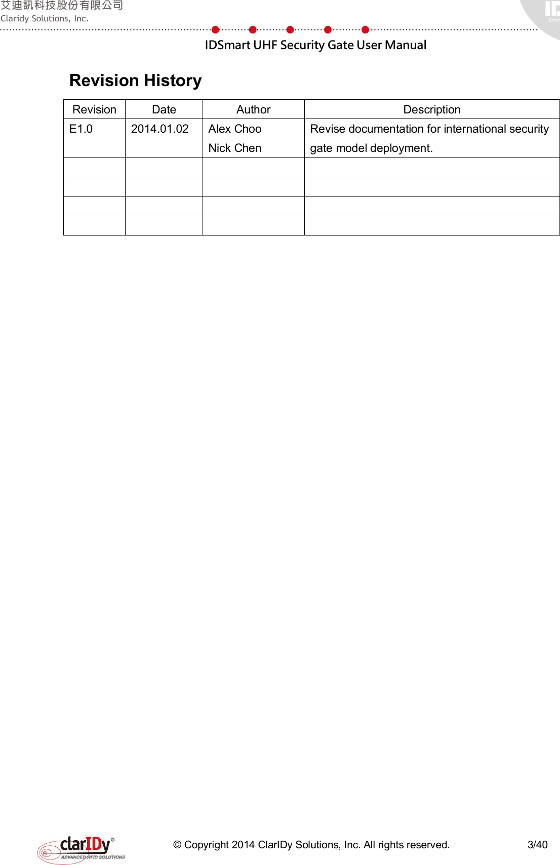
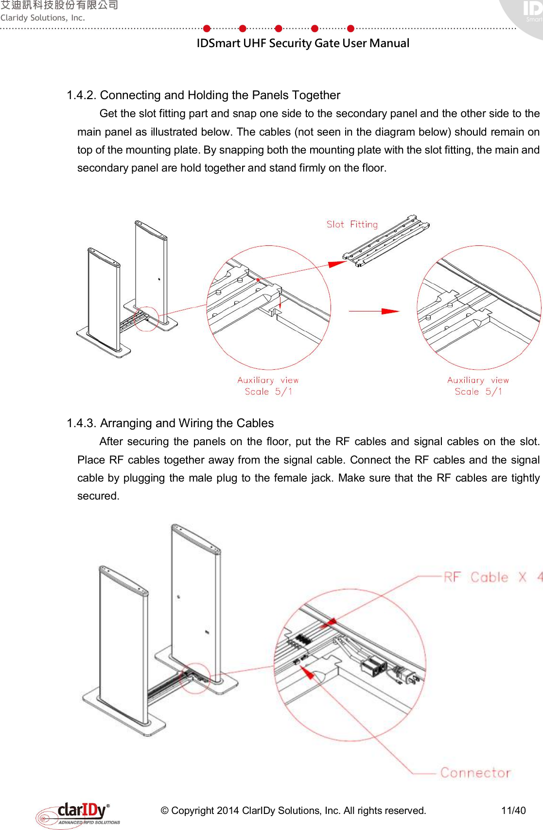

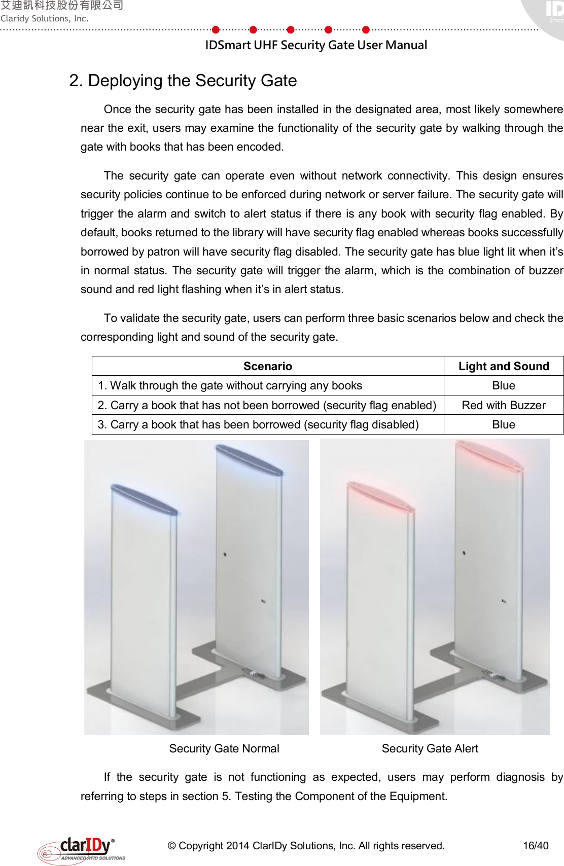
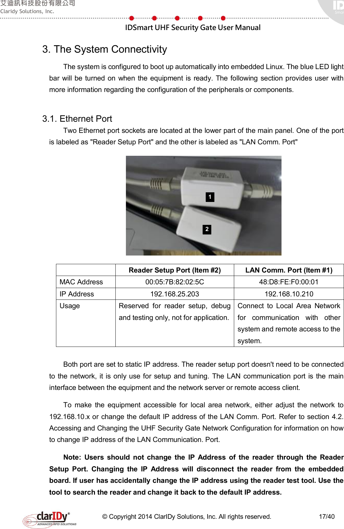
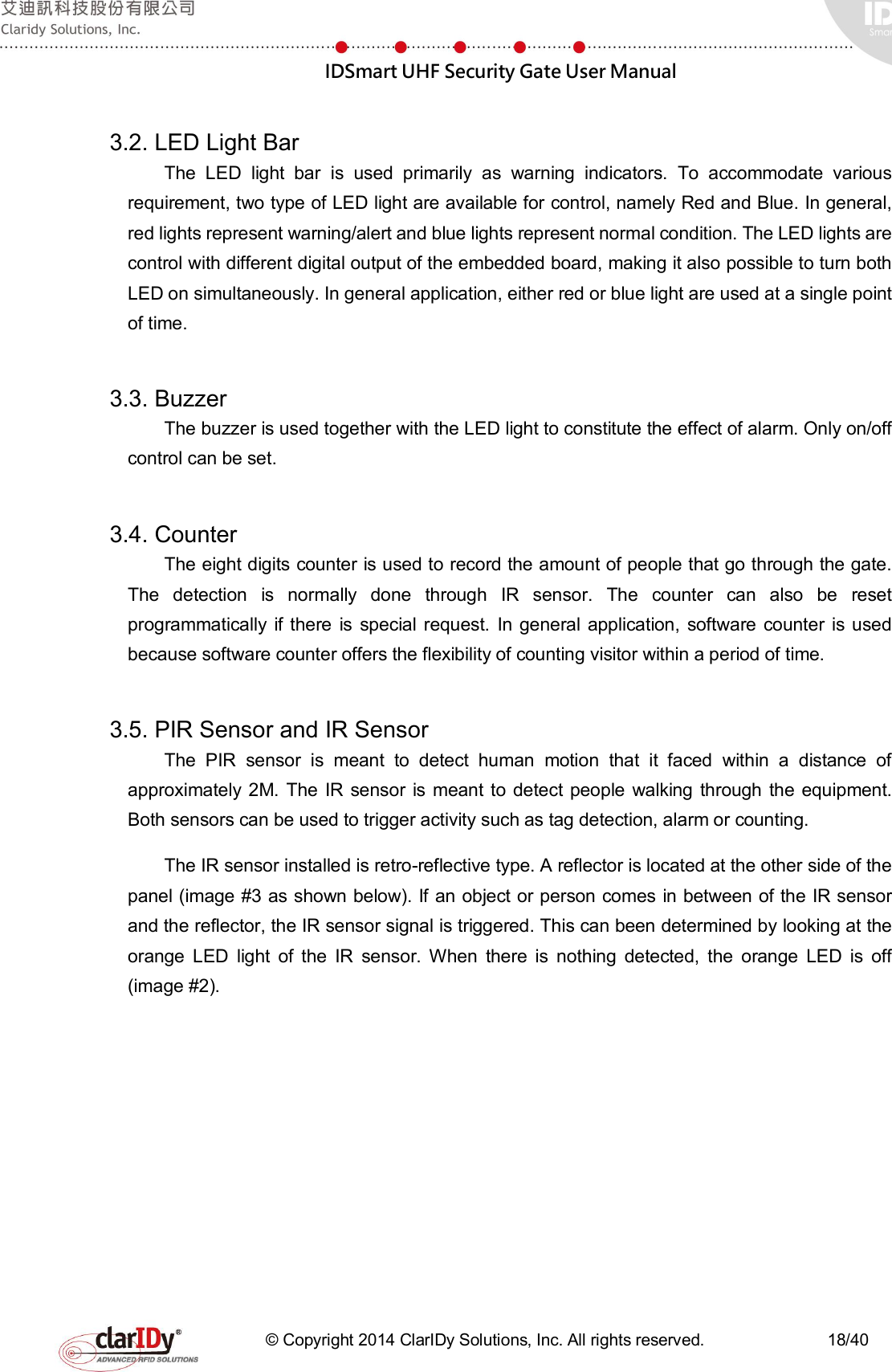
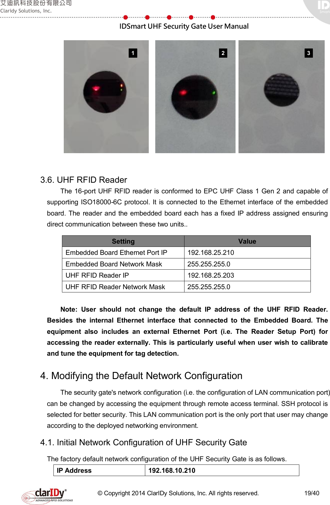
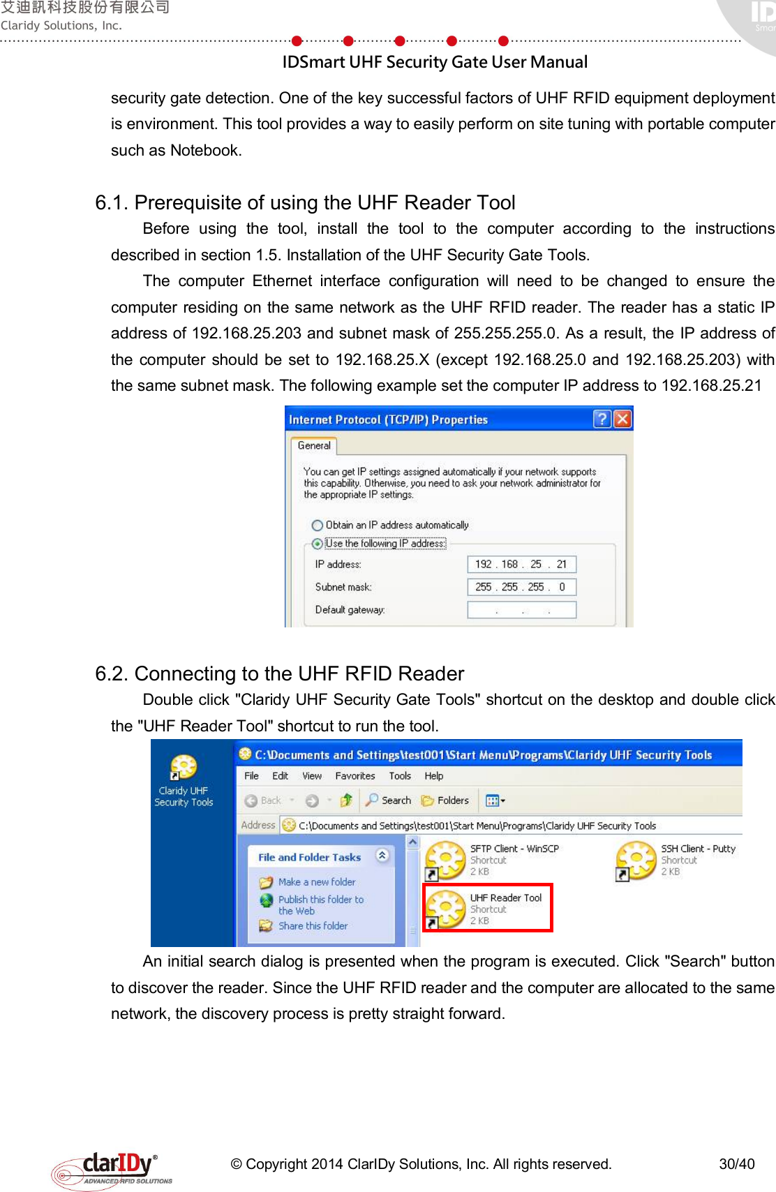
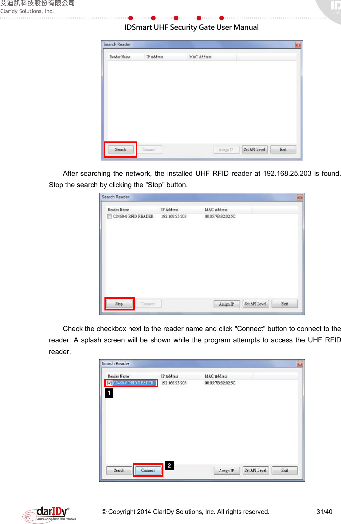
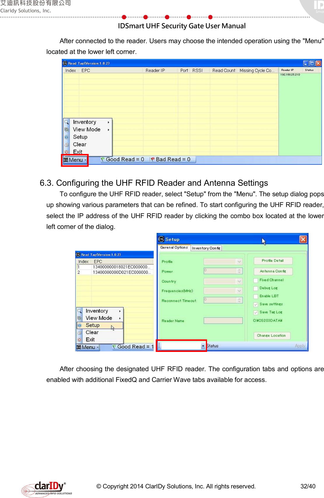
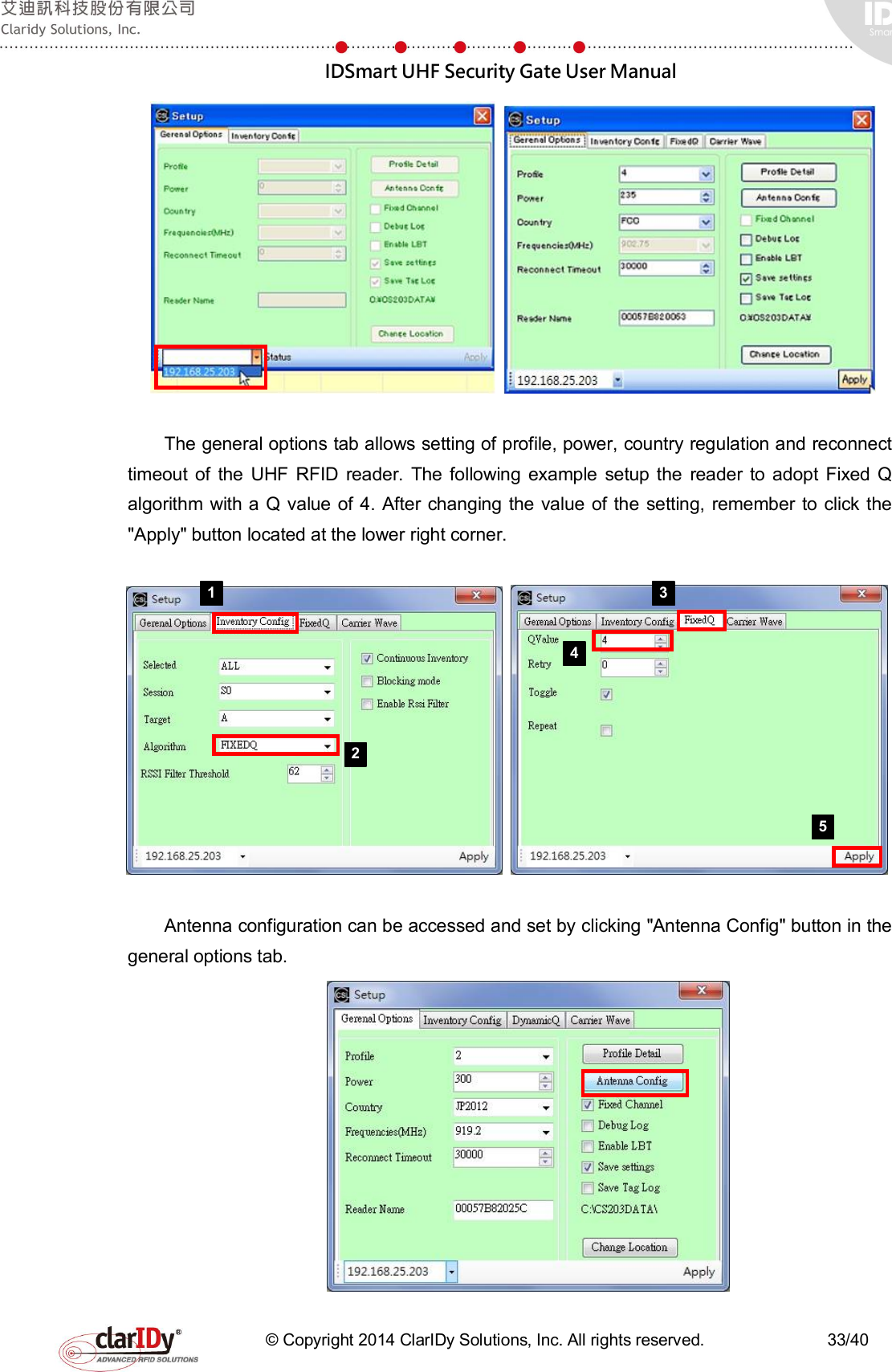
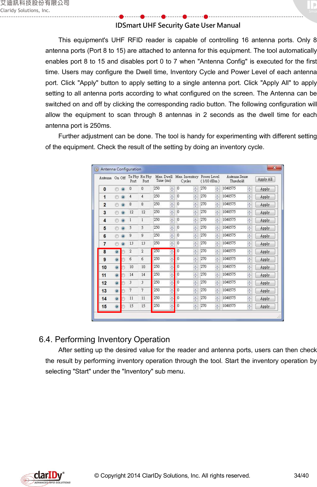
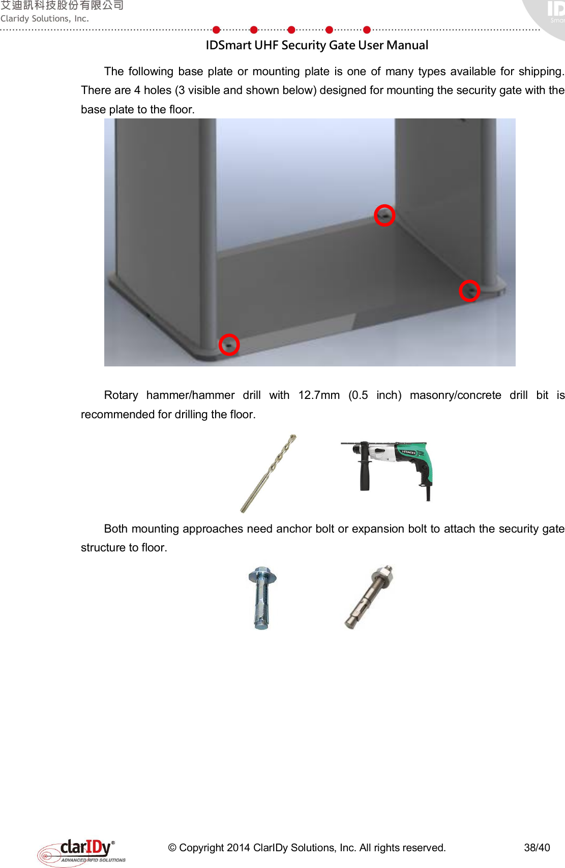
![IDSmart UHF Security Gate User Manual © Copyright 2014 ClarIDy Solutions, Inc. All rights reserved. 24/40 run the "./demo.sh" shell script. sshuser@freescale ~$ cd /usr/local/security-gate-demo sshuser@freescale /usr/local/security-gate-demo$ ./demo.sh After executing the demo program, the context shell of the demo program is loaded. Type "help" to see commands available for the demo program. Please refer to the SDK reference manual for detailed usage. sshuser@freescale ~$ cd /usr/local/security-gate-demo sshuser@freescale /usr/local/security-gate-demo$ ./demo.sh [Demo] Start Demo Program. $> $>help [Demo] Commands :: [Demo] Command Description [Demo] "help" "Display all command and description" [Demo] "connect" "Connect to CS468" [Demo] "disconnect" "Disconnect from CS468" [Demo] "inventory" "Start Inventory" [Demo] "read-user-memory" "Read the user memory data" [Demo] "read-tid" "Read the TID data" [Demo] "stop" "Stop Operation" [Demo] "set-power" "Set the antenna power." [Demo] "get-power" "Get the antenna power." [Demo] "enable-ant" "Enable the antenna port" [Demo] "disable-ant" "Disable the antenna port" [Demo] "set-fix-q" "Set Fix-Q Algorithm" [Demo] "set-dwell-time" "Set the dwell time of the antenna" [Demo] "set-ant-inv-count" "Set the inventory round counts of the antenna" [Demo] "start-scenario" "Run Scenario" [Demo] "stop-scenario" "Stop Scenario" [Demo] "get-ir-state" "Get the state of the IR pin (0 or 1)" [Demo] "start-ir" "Start monitor the IR pin state." [Demo] "stop-ir" "Stop monitor the IR pin state" [Demo] "get-pir-state" "Get the state of the PIR pin (0 or 1)" [Demo] "start-pir" "Start monitor the PIR pin state." [Demo] "stop-pir" "Stop monitor the PIR pin state" [Demo] "turn-red-led-on" "Turn red led on" [Demo] "turn-red-led-off" "Turn red led off" [Demo] "blink-red-led" "Blink the red led" [Demo] "turn-blue-led-on" "Turn blue led on" [Demo] "turn-blue-led-off" "Turn blue led off" [Demo] "blink-blue-led" "Blink the blue led" [Demo] "add-counter" "Add counter by 1" [Demo] "reset-counter" "Reset counter " [Demo] "beep" "Make beep." [Demo] "trigger-alarm" "Trigger Alram." [Demo] "turn-reserved-port-on" "Turn on the reserved port." [Demo] "turn-reserved-port-off" "Turn off the reserved port" [Demo] "q" "quit " $> 5.4. LED Light Bar Verification The two-color LED light bar can be controlled separately. The following example turns the blue LED off and turn the red LED on. The blink function allows user to blink the LED light bar for a desired time in seconds. The example also makes the red LED blink for 5 seconds. [Demo] Start Demo Program. $> $>turn-blue-led-off [Demo] Turn Blue led off $>turn-red-led-on [Demo] Turn the red led on](https://usermanual.wiki/ClarIDy-Solutions/SUG-100-04/User-Guide-2888841-Page-24.png)
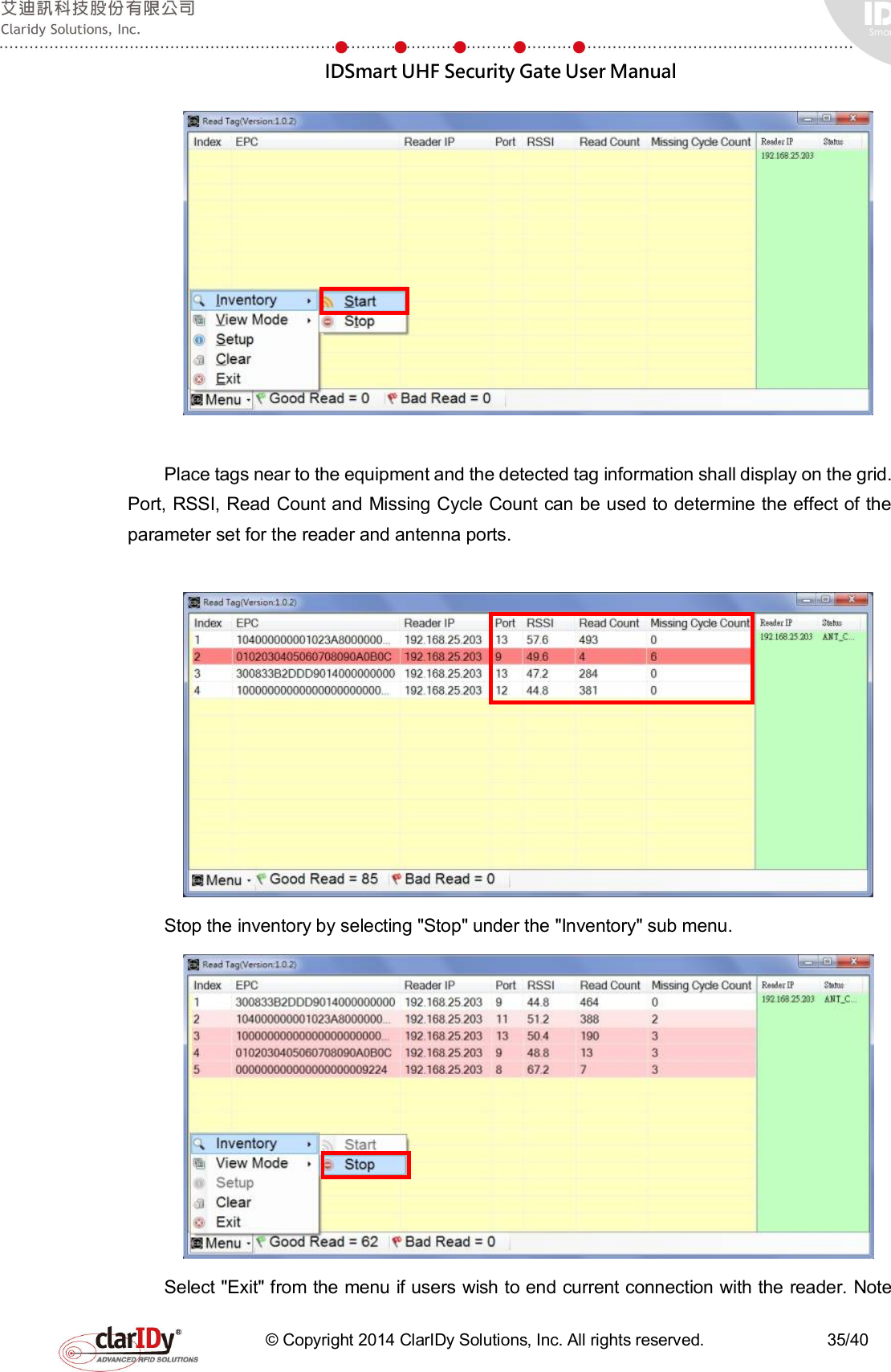
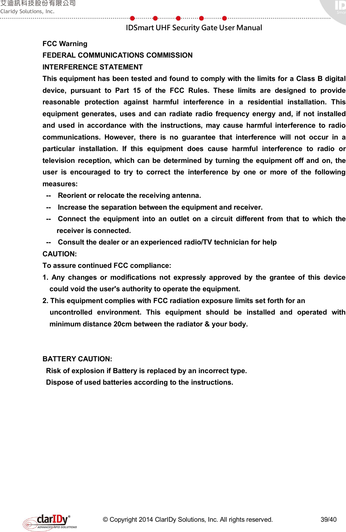
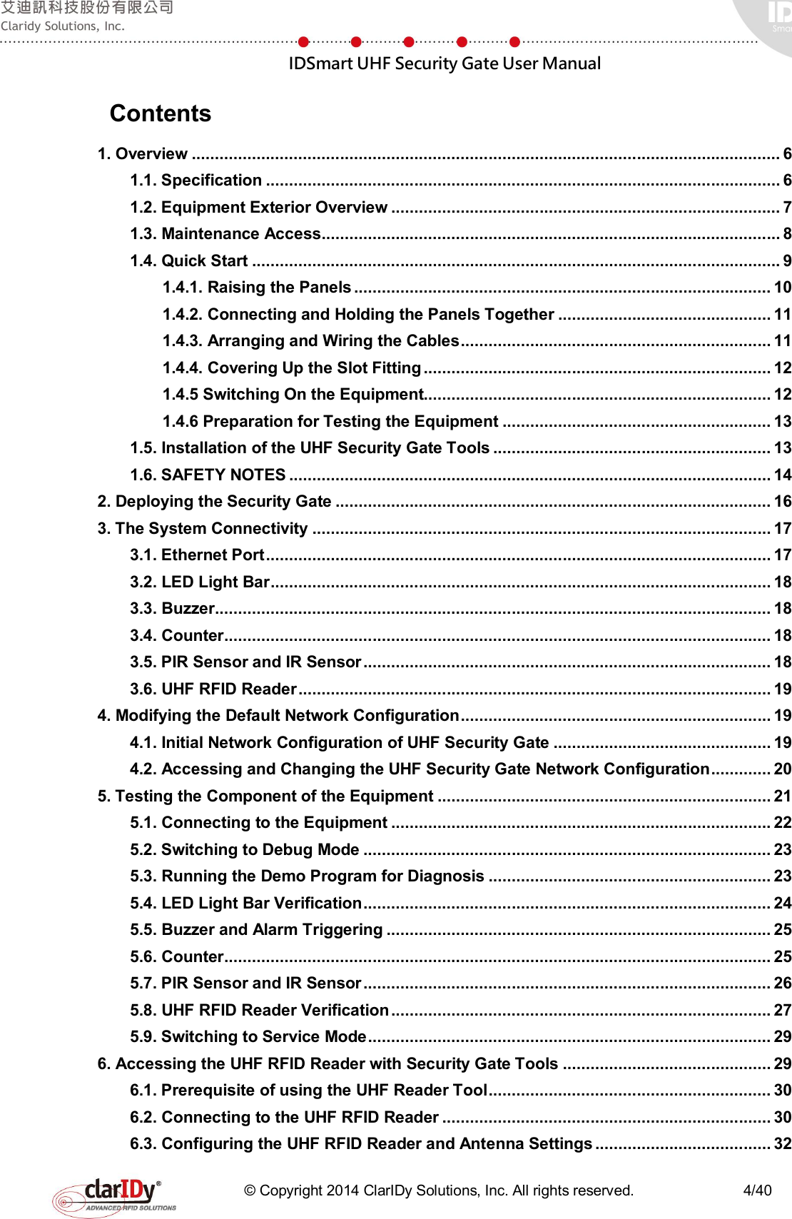
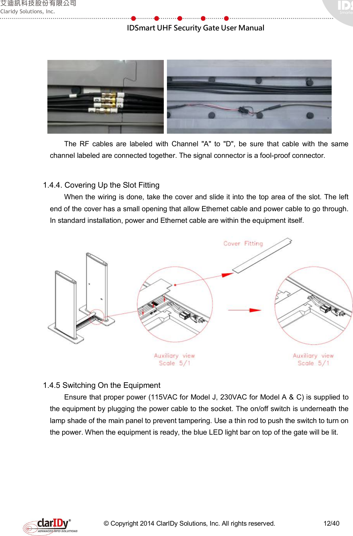
![IDSmart UHF Security Gate User Manual © Copyright 2014 ClarIDy Solutions, Inc. All rights reserved. 25/40 $>blink-red-led 5 [Demo] Blink red led :: "5" seconds $> From left to right: Both LED lights are off, blue LED lights on, red LED lights on. 5.5. Buzzer and Alarm Triggering Users can control the number of second that a buzzer beeps. By combining the buzzer beeping and red LED light bar blinking, alarm effect can be created. The example causes the buzzer to beep for 7 seconds and then sound the alarm for 3 seconds (red lights and buzzer will be activated for 3 seconds). [Demo] Start Demo Program. $> $>beep 7 [Demo] Beep in "7" seconds $>trigger-alarm 3 [Demo] Trigger alarm in "3" seconds $> 5.6. Counter Users may increase the counting or reset the counting of the counter. The following example increases the counter five times and then reset it. The counter current count can be checked by looking at the lower part of the main panel. The reset counter is per request special feature which might not available for most model. [Demo] Start Demo Program. $> $>add-counter [Demo] Plus 1 in the Counter $>add-counter [Demo] Plus 1 in the Counter $>add-counter [Demo] Plus 1 in the Counter $>add-counter [Demo] Plus 1 in the Counter $>add-counter [Demo] Plus 1 in the Counter $> $>reset-counter [Demo] Reset the Counter $>](https://usermanual.wiki/ClarIDy-Solutions/SUG-100-04/User-Guide-2888841-Page-25.png)
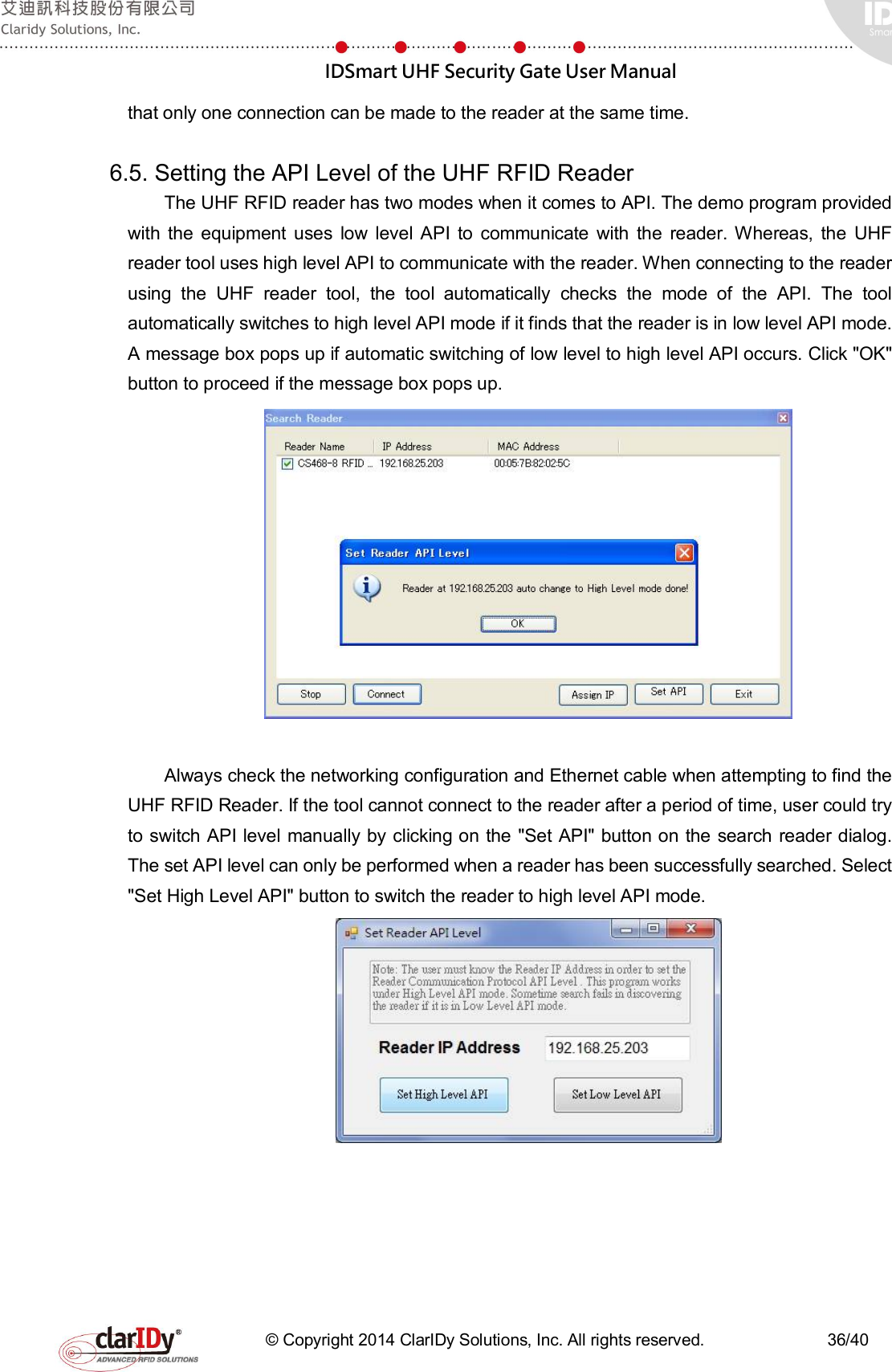
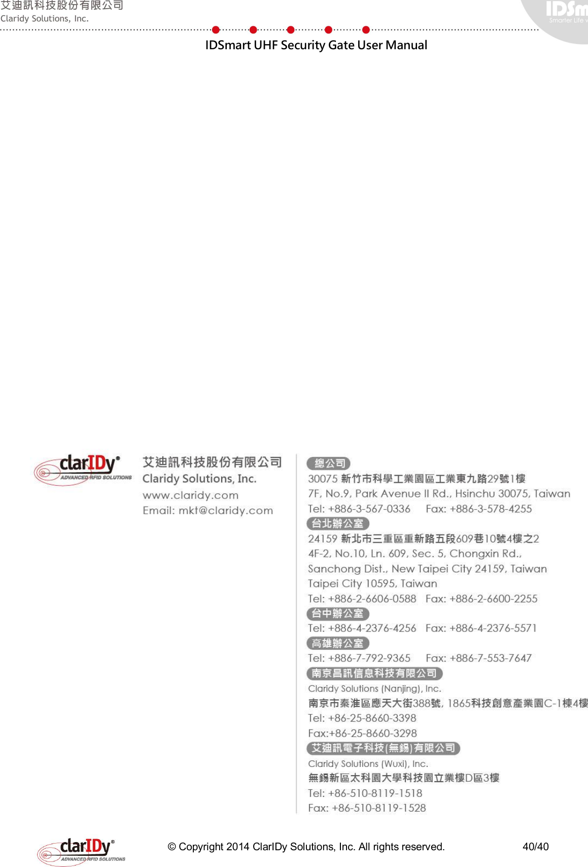
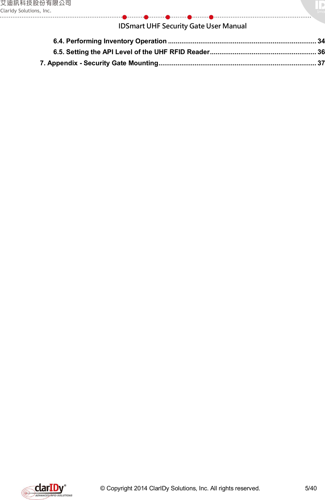
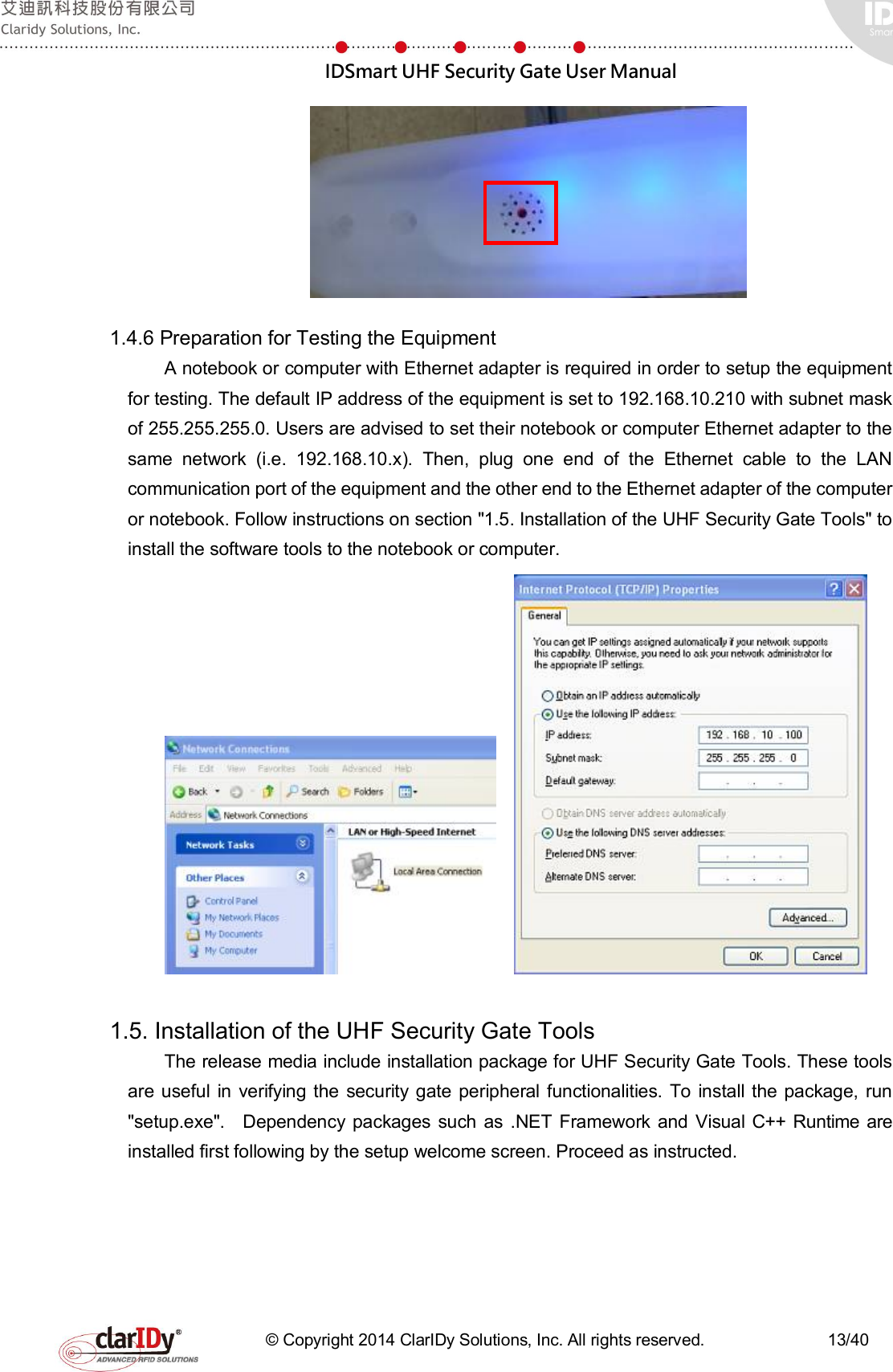
![IDSmart UHF Security Gate User Manual © Copyright 2014 ClarIDy Solutions, Inc. All rights reserved. 26/40 Current count at 5 After reset of counter 5.7. PIR Sensor and IR Sensor Both sensors are input to the system, which mean that they are triggered by external event. The sensors are put to monitoring the external event, which is people coming near the equipment or passing through the equipment. To make the testing straight forward, the buzzer beeps once when the sensors are triggered. Due to the nature of fast sensor response, the sensor response are deliberately slowed down through software programming so that the equipment is not over reacted or too sensitive to motion. The following example starts the PIR sensor monitoring process and stop it [Demo] Start Demo Program. $> $>start-pir [Demo] Start Monitor the PIR $>[Demo] PIR Detected [Demo] PIR Detected [Demo] PIR Detected [Demo] PIR Detected $> $>stop-pir [Demo] Stop Monitor the PIR $> When PIR sensor monitoring process started, stand in front of the equipment and move around (e.g. walk toward the gate). When the PIR sensor detects the motion, the buzzer's beep can be heard. Once detected, the PIR sensor stop detecting until one second later.](https://usermanual.wiki/ClarIDy-Solutions/SUG-100-04/User-Guide-2888841-Page-26.png)
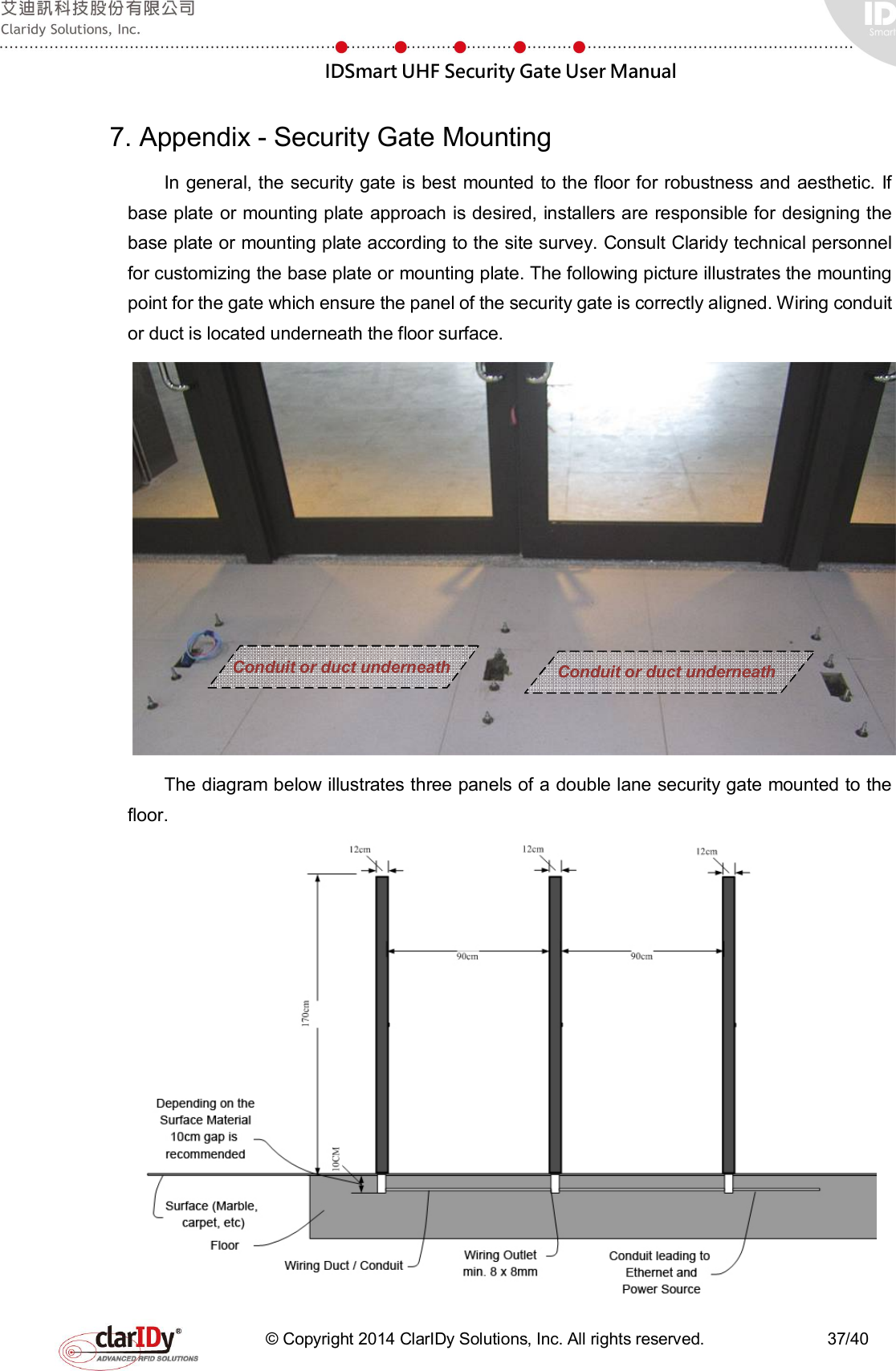
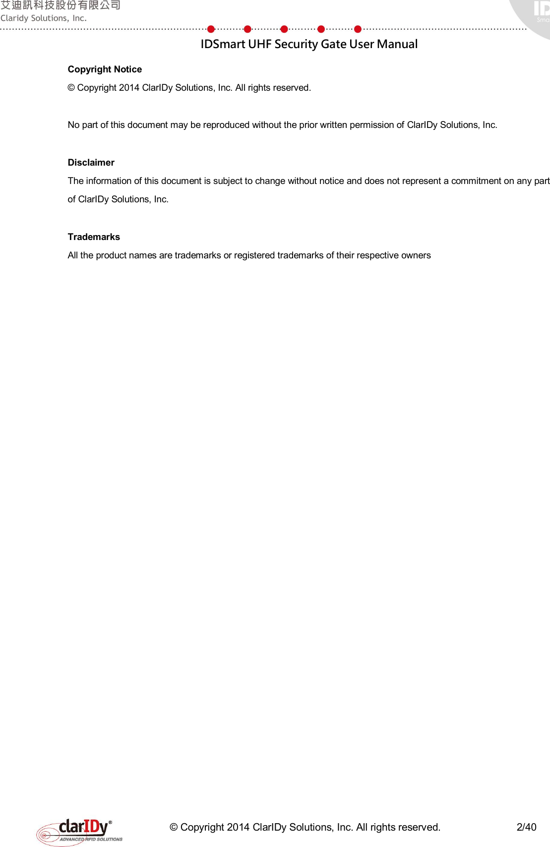
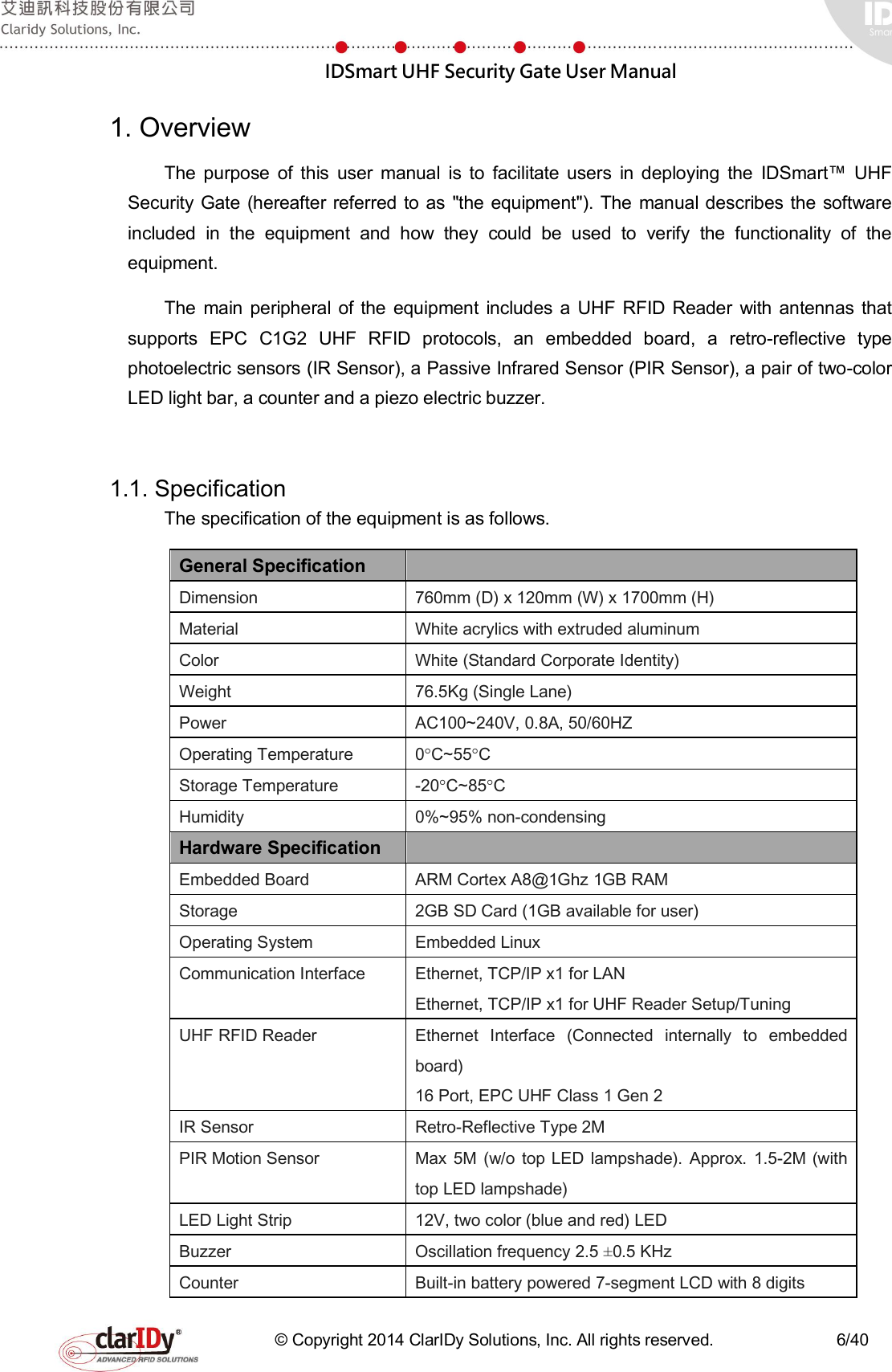
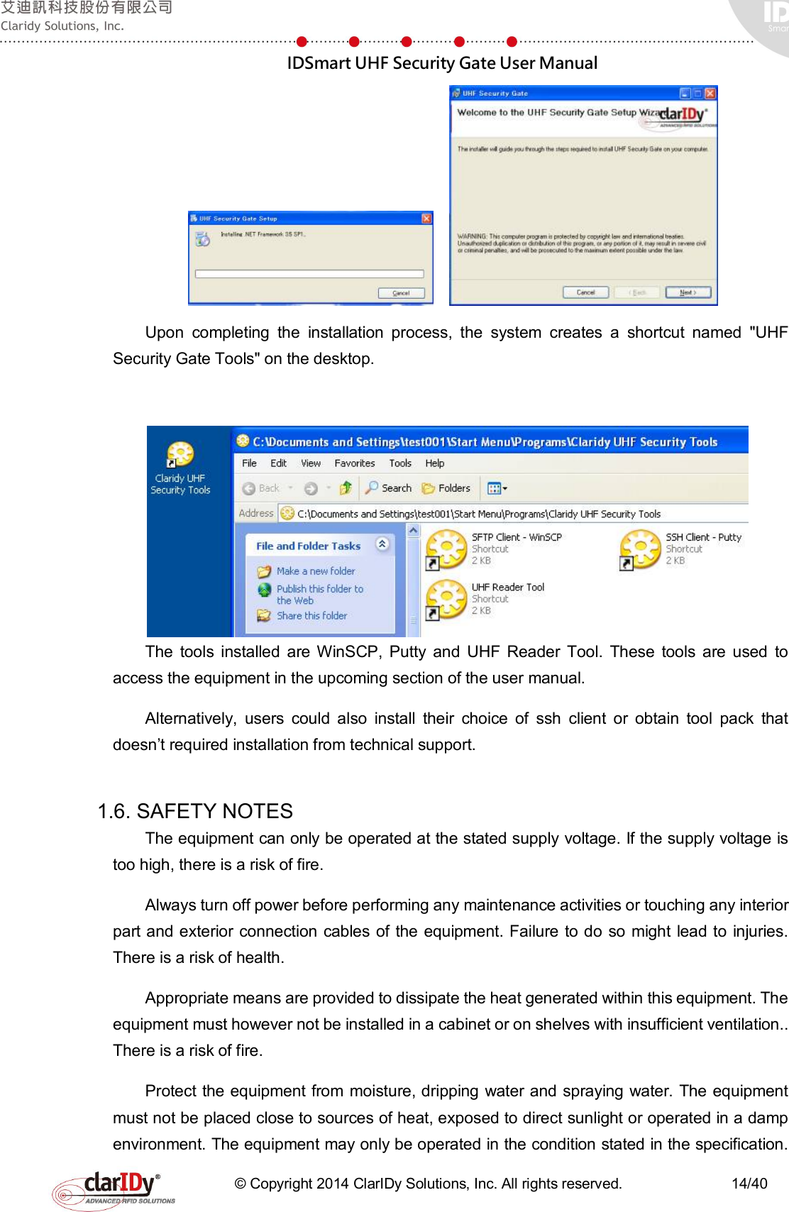
![IDSmart UHF Security Gate User Manual © Copyright 2014 ClarIDy Solutions, Inc. All rights reserved. 27/40 The following example starts the IR sensor monitoring process and stop it [Demo] Start Demo Program. $> $>start-ir [Demo] Start Monitor the IR $>[Demo] IR Detected [Demo] IR Detected [Demo] IR Detected [Demo] IR Detected $> $>stop-ir [Demo] Stop Monitor the IR $> When IR sensor is started, walk through the security gate. The buzzer beeps when the user passes through the IR sensor. 5.8. UHF RFID Reader Verification The reader is connected internally to the embedded board through Ethernet port. The](https://usermanual.wiki/ClarIDy-Solutions/SUG-100-04/User-Guide-2888841-Page-27.png)
![IDSmart UHF Security Gate User Manual © Copyright 2014 ClarIDy Solutions, Inc. All rights reserved. 28/40 reader is assigned a static IP address and connected to a designated IP address of the embedded board. User should not change this IP address as they are private internal IP address. The internal IP address of the UHF reader is set to 192.168.25.203. The following example starts a reader connection and set the Q value parameter of the reader. Q value is one of many parameters of UHF EPC C1G2. The parameters can be adjusted based on various scenario, this is out of the scope of this user manual. Consult RFID technical expert for optimization of these values. Connection to the reader is required before performing any inventory or tag reading operation. [Demo] Start Demo Program. $> $>connect 192.168.25.203 [Demo] Connect to the Reader. IP : "192.168.25.203" [Demo] CS468 Connected!! [Demo] Initial the default parameters. [Demo] Disable 0-port antenna and enable the 8 ~ 15 port antenna. [Demo] Set dwell time as 250 [Demo] Set antenna power as 270 $> $>set-fix-q [Demo] Error :: The count of parameters is not match with the command. CMD:: "set-fix-q" [Demo] Usages :: "set-fix-q [q-value] [retry-count] [toggle] [runTillZero]" $> $>set-fix-q 4 0 1 1 [Demo] Set Fix Q : 4 ,Retry Count : 0 , is Toggle : true , is Run Till Zero : true $> Prepare several books with tag or UHF RFID tag and place those tags near the equipment. Depending on the environment, the reading radius could be around one to two meters. To test the reader, we place the UHF RFID tags in between the two panels of the security gate. The following example performs an inventory cycle. Information of tags, i.e. PC, EPC and RSSI of the detected tags are displayed, regardless of whether it repeats on different antenna. $> $>set-fix-q 4 0 1 1 [Demo] Set Fix Q : 4 ,Retry Count : 0 , is Toggle : true , is Run Till Zero : true $> $>inventory [Demo] Start Inventory [Demo] Tag PC:: "4800" EPC :: "104000000001023a80000003525c00010000" , RSSI :: "66.4" [Demo] Tag Detected [Demo] Tag PC:: "4800" EPC :: "104000000001023a80000003525c00010000" , RSSI :: "60" [Demo] Tag Detected [Demo] Tag PC:: "4800" EPC :: "104000000001023a80000003525c00010000" , RSSI :: "64" [Demo] Tag Detected [Demo] Tag PC:: "4800" EPC :: "104000000001023a80000003525c00010000" , RSSI :: "61.6" [Demo] Tag Detected [Demo] Tag PC:: "4800" EPC :: "104000000001023a80000003525c00010000" , RSSI :: "62.4" [Demo] Tag Detected [Demo] Tag PC:: "4800" EPC :: "104000000001023a80000003525c00010000" , RSSI :: "62.4" [Demo] Tag Detected [Demo] Tag PC:: "4800" EPC :: "104000000001023a80000003525c00010000" , RSSI :: "76.8" [Demo] Tag Detected [Demo] Tag PC:: "4800" EPC :: "104000000001023a80000003525c00010000" , RSSI :: "76.8" [Demo] Tag Detected [Demo] Tag PC:: "3000" EPC :: "300833b2ddd9014000000000" , RSSI :: "50.4" [Demo] Tag Detected [Demo] Tag PC:: "3000" EPC :: "300833b2ddd9014000000000" , RSSI :: "48.8" [Demo] Tag Detected](https://usermanual.wiki/ClarIDy-Solutions/SUG-100-04/User-Guide-2888841-Page-28.png)
![IDSmart UHF Security Gate User Manual © Copyright 2014 ClarIDy Solutions, Inc. All rights reserved. 29/40 [Demo] Tag PC:: "4800" EPC :: "104000000001023a80000003525c00010000" , RSSI :: "73.6" [Demo] Tag Detected [Demo] Tag PC:: "4800" EPC :: "104000000001023a80000003525c00010000" , RSSI :: "67.2" [Demo] Tag Detected [Demo] Tag PC:: "4800" EPC :: "104000000001023a80000003525c00010000" , RSSI :: "74.4" [Demo] Tag Detected [Demo] Tag PC:: "4800" EPC :: "104000000001023a80000003525c00010000" , RSSI :: "76" : (truncated) : $> There are eight antenna (port 8 to port 15) installed for the equipment, to set antenna power and dwell time, run the command with appropriate parameter, check the SDK reference manual for further usage. The following example disables antenna on port no.8 and enables it. Then, a disconnection to the reader is done follows by exiting the context shell. Note: only one connection can be connected to the reader at the same time. $> $>disable-ant 8 [Demo] Disable Antenna :: 8 $> $>enable-ant 8 [Demo] Enable Antenna :: 8 $> $>disconnect $> $>q sshuser@freescale ~/security-gate-demo$ 5.9. Switching to Service Mode Once the user has completed the diagnosis, the system should be switched to service mode. The service mode script is located in the home directory of the "sshuser". Change the directory to "/home/sshuser". the run the debug mode script by typing "./security-gate-DebugMode.sh" in the shell. sshuser@freescale /usr/local/security-gate-demo$ cd /home/sshuser sshuser@freescale ~$ ./security-gate-ServiceMode.sh When the script executed, the security gate will reboot and switch to service mode. Always switch to debug mode when performing diagnostic and configuration of the system. In service mode, the security gate LED will be red when restarting and turn to blue when it is ready to service. If the LED doesn’t switch from red to blue within 20sec, login to the system again to correct the issue. 6. Accessing the UHF RFID Reader with Security Gate Tools The UHF RFID Reader is internally connected to the embedded board. To facilitate testing and tuning, the security gate tools include a program that can directly connect to the reader through the Ethernet Port labeled "Reader Setup Port". This tool is especially useful when developers wish to test different setting of the reader and antenna to optimize the result of the](https://usermanual.wiki/ClarIDy-Solutions/SUG-100-04/User-Guide-2888841-Page-29.png)