ClarIDy Solutions SUG-100-04 UHF Single-lane Security Gate User Manual
ClarIDy Solutions, Inc. UHF Single-lane Security Gate
User Manual

艾迪訊科技股份有限公司
Claridy Solutions, Inc.
www.claridy.com
E-mail:mkt@claridy.com
IDSmart UHF Security Gate
User Manual

IDSmart UHF Security Gate User Manual
© Copyright 2014 ClarIDy Solutions, Inc. All rights reserved. 2/40
Copyright Notice
© Copyright 2014 ClarIDy Solutions, Inc. All rights reserved.
No part of this document may be reproduced without the prior written permission of ClarIDy Solutions, Inc.
Disclaimer
The information of this document is subject to change without notice and does not represent a commitment on any part
of ClarIDy Solutions, Inc.
Trademarks
All the product names are trademarks or registered trademarks of their respective owners
IDSmart UHF Security Gate User Manual
© Copyright 2014 ClarIDy Solutions, Inc. All rights reserved. 3/40
Revision History
Revision
Date Author Description
E1.0 2014.01.02 Alex Choo
Nick Chen
Revise documentation for international security
gate model deployment.

IDSmart UHF Security Gate User Manual
© Copyright 2014 ClarIDy Solutions, Inc. All rights reserved. 4/40
Contents
1. Overview ............................................................................................................................... 6
1.1. Specification ............................................................................................................... 6
1.2. Equipment Exterior Overview .................................................................................... 7
1.3. Maintenance Access ................................................................................................... 8
1.4. Quick Start .................................................................................................................. 9
1.4.1. Raising the Panels .......................................................................................... 10
1.4.2. Connecting and Holding the Panels Together .............................................. 11
1.4.3. Arranging and Wiring the Cables ................................................................... 11
1.4.4. Covering Up the Slot Fitting ........................................................................... 12
1.4.5 Switching On the Equipment........................................................................... 12
1.4.6 Preparation for Testing the Equipment .......................................................... 13
1.5. Installation of the UHF Security Gate Tools ............................................................ 13
1.6. SAFETY NOTES ........................................................................................................ 14
2. Deploying the Security Gate .............................................................................................. 16
3. The System Connectivity ................................................................................................... 17
3.1. Ethernet Port ............................................................................................................. 17
3.2. LED Light Bar ............................................................................................................ 18
3.3. Buzzer ........................................................................................................................ 18
3.4. Counter ...................................................................................................................... 18
3.5. PIR Sensor and IR Sensor ........................................................................................ 18
3.6. UHF RFID Reader ...................................................................................................... 19
4. Modifying the Default Network Configuration ................................................................... 19
4.1. Initial Network Configuration of UHF Security Gate ............................................... 19
4.2. Accessing and Changing the UHF Security Gate Network Configuration ............. 20
5. Testing the Component of the Equipment ........................................................................ 21
5.1. Connecting to the Equipment .................................................................................. 22
5.2. Switching to Debug Mode ........................................................................................ 23
5.3. Running the Demo Program for Diagnosis ............................................................. 23
5.4. LED Light Bar Verification ........................................................................................ 24
5.5. Buzzer and Alarm Triggering ................................................................................... 25
5.6. Counter ...................................................................................................................... 25
5.7. PIR Sensor and IR Sensor ........................................................................................ 26
5.8. UHF RFID Reader Verification .................................................................................. 27
5.9. Switching to Service Mode ....................................................................................... 29
6. Accessing the UHF RFID Reader with Security Gate Tools ............................................. 29
6.1. Prerequisite of using the UHF Reader Tool ............................................................. 30
6.2. Connecting to the UHF RFID Reader ....................................................................... 30
6.3. Configuring the UHF RFID Reader and Antenna Settings ...................................... 32

IDSmart UHF Security Gate User Manual
© Copyright 2014 ClarIDy Solutions, Inc. All rights reserved. 5/40
6.4. Performing Inventory Operation .............................................................................. 34
6.5. Setting the API Level of the UHF RFID Reader ........................................................ 36
7. Appendix - Security Gate Mounting ................................................................................... 37
IDSmart UHF Security Gate User Manual
© Copyright 2014 ClarIDy Solutions, Inc. All rights reserved. 6/40
1. Overview
The purpose of this user manual is to facilitate users in deploying the IDSmart™ UHF
Security Gate (hereafter referred to as "the equipment"). The manual describes the software
included in the equipment and how they could be used to verify the functionality of the
equipment.
The main peripheral of the equipment includes a UHF RFID Reader with antennas that
supports EPC C1G2 UHF RFID protocols, an embedded board, a retro-reflective type
photoelectric sensors (IR Sensor), a Passive Infrared Sensor (PIR Sensor), a pair of two-color
LED light bar, a counter and a piezo electric buzzer.
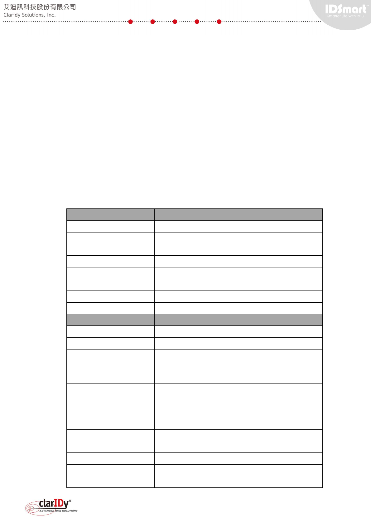
1.1. Specification
The specification of the equipment is as follows.
General Specification
Dimension 760mm (D) x 120mm (W) x 1700mm (H)
Material White acrylics with extruded aluminum
Color White (Standard Corporate Identity)
Weight 76.5Kg (Single Lane)
Power AC100~240V, 0.8A, 50/60HZ
Operating Temperature 0°C~55°C
Storage Temperature -20°C~85°C
Humidity 0%~95% non-condensing
Hardware Specification
Embedded Board ARM Cortex A8@1Ghz 1GB RAM
Storage 2GB SD Card (1GB available for user)
Operating System Embedded Linux
Communication Interface Ethernet, TCP/IP x1 for LAN
Ethernet, TCP/IP x1 for UHF Reader Setup/Tuning
UHF RFID Reader Ethernet Interface (Connected internally to embedded
board)
16 Port, EPC UHF Class 1 Gen 2
IR Sensor Retro-Reflective Type 2M
PIR Motion Sensor Max 5M (w/o top LED lampshade). Approx. 1.5-2M (with
top LED lampshade)
LED Light Strip 12V, two color (blue and red) LED
Buzzer Oscillation frequency 2.5 ±0.5 KHz
Counter Built-in battery powered 7-segment LCD with 8 digits
IDSmart UHF Security Gate User Manual
© Copyright 2014 ClarIDy Solutions, Inc. All rights reserved. 7/40
UHF RFID Specification
Protocol EPC UHF Class 1 Gen 2, ISO18000-6C
Operating Frequency US: 902 – 928MHz / TW: 922 – 928MHz /
SG, HK: 920 – 925MHz / CHN: 920.5 – 924.5MHz / JP:
916.8-923.4MHz
RF Output Power 28dBm
Antenna Gain 5.5dBi
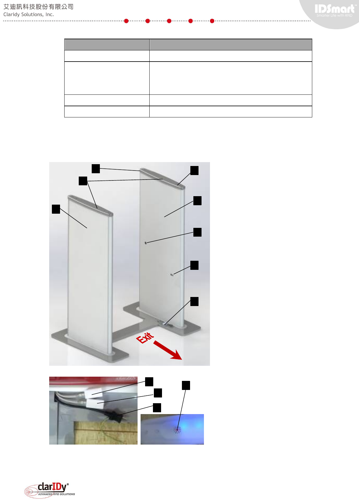
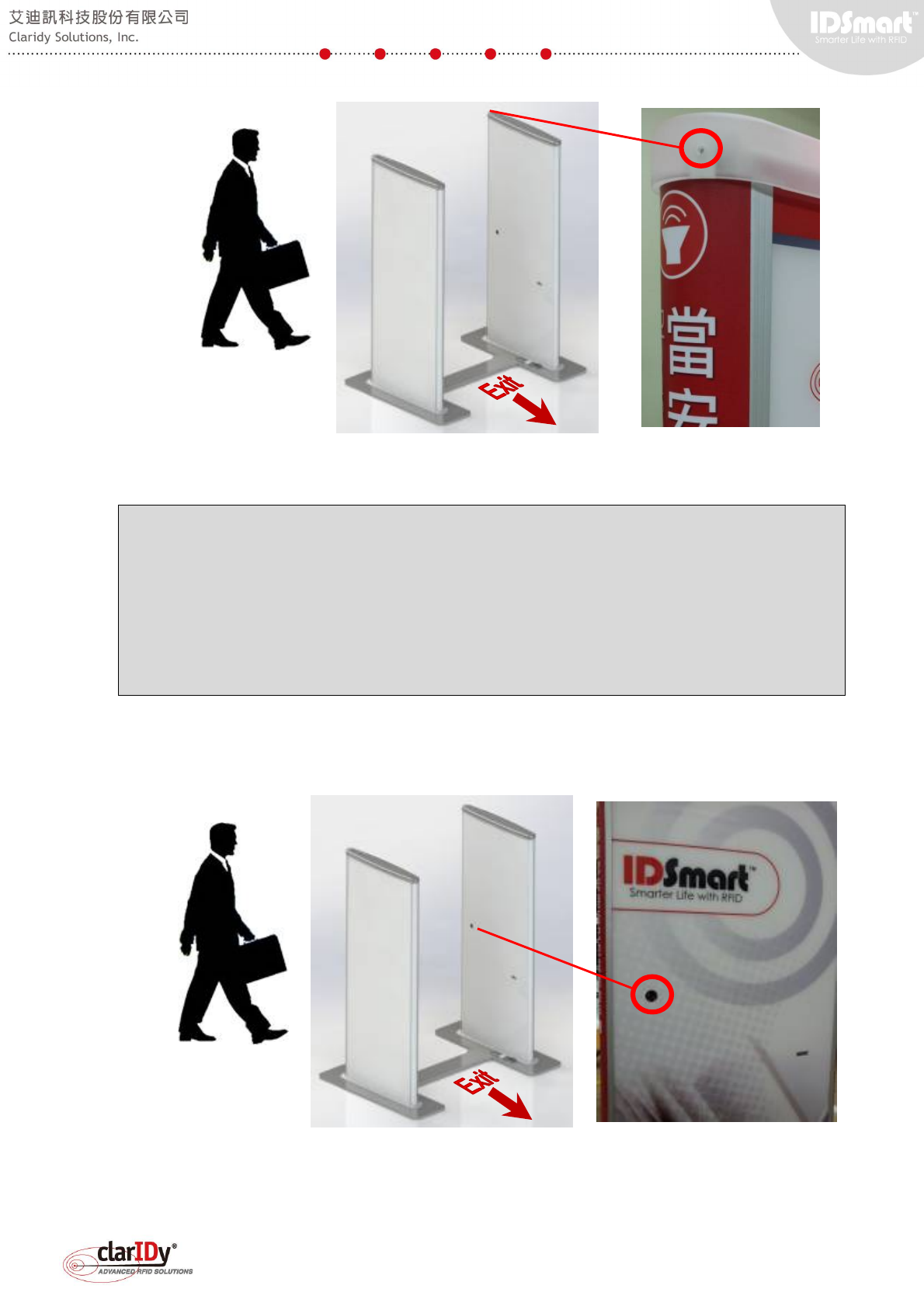
1.2. Equipment Exterior Overview
The following exhibits provide a general concept of whereabouts the peripheral located.
45° view from the outer area of the
equipment
A. Main Panel
B. Secondary Panel
1. On/Off Switch
2. PIR Sensor
3. Two-color LED Light Bar
(Warning Indicator)
4. IR Sensor
5. Counter
C. Ethernet Port and Power
6. LAN Communication Port
7. Reader Setup Port
8. Power Cable
B
A
C*
2
4
5
1
3
6
7
8
1
IDSmart UHF Security Gate User Manual
© Copyright 2014 ClarIDy Solutions, Inc. All rights reserved. 8/40
* Ethernet Port and Power outlet could be located at the inner side or outer side of the door
panel
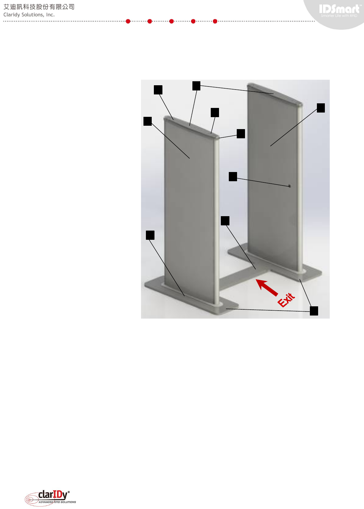
45° view from the inner area
of the equipment
A. Main Panel
B. Secondary Panel
D. Slot Fitting (Holds both
panels and connect the
mounting plates)
E. Mounting Plate
1. On/Off Switch
2. PIR Sensor
3. Two-color LED Light
Bar (Warning Indicator)
9. IR Reflector
10. Buzzer outlet
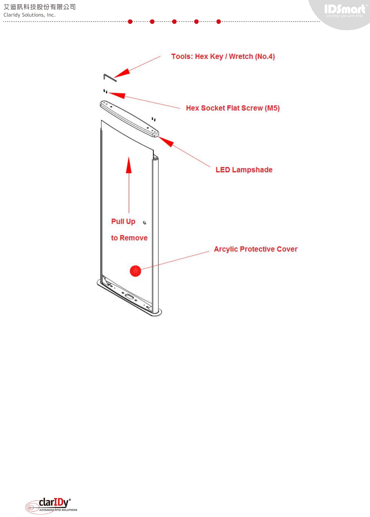
1.3. Maintenance Access
The equipment maintenance required proper tools and training. The scope of the security
gate maintenance is not covered in this user manual. In general, the deployment of application
and control of peripherals can be done through the Ethernet interface. The equipment
maintenance access is only required when there is component failure. Users should consult
Claridy technical personnel for proper training before performing any maintenance activity on
the equipment. The security gate maintenance access can be gained through removing the
lampshade of the gate and the arcylic protective cover with a no.4 hex key or wretch. Note that
unauthorized changes, removal or tampering to the component/structure/wiring of the
equipment makes the provided warranty/guarantee null and void.
A
D
3
2
9
B
E
10
1
C*
IDSmart UHF Security Gate User Manual
© Copyright 2014 ClarIDy Solutions, Inc. All rights reserved. 9/40
1.4. Quick Start
There are four different parts in the delivery package, which is, (a) the main panel of the
gate, (b) the secondary panel of the gate, (c) the slot fitting that connects the mounting plate of
the gate panels, (d) the cover of the slot fitting.
The standard product does not come with mounting plate or base plate. The enclosed
mounting plates and slot fitting are designed to facilitate the testing of the equipment. In actual
deployment, the equipment is mounted to the floor and cabling is done through a wiring conduit
or duct (See section 7. Appendix - Security Gate Mounting).
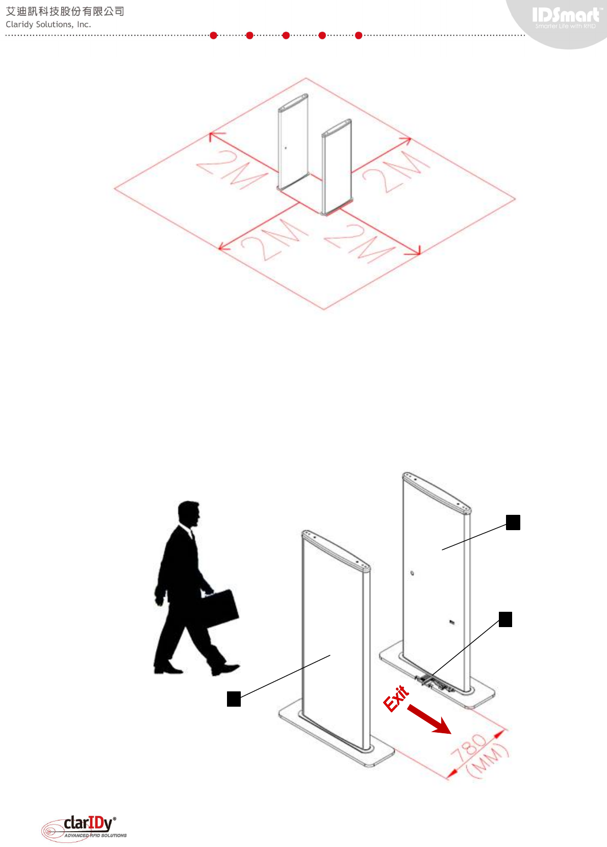
Upon unpacking the equipment, users should assemble the security gate in accordance to
the steps described in this section. The equipment must be assembled on a flat and level floor.
Failure of doing so will cause unexpected behavior and result. For best result, allow a 2 meter
clearance space for the equipment, as illustrated below.
IDSmart UHF Security Gate User Manual
© Copyright 2014 ClarIDy Solutions, Inc. All rights reserved. 10/40
1.4.1. Raising the Panels
Unpack the main and secondary panel. The main panel can be identified by either looking
at the cable or the counter of the panel. The main panel should have 4 short RF cables, 2
Ethernet connector socket, a signal cable and a power cable coming out from the mounting
plate. Whereas, the secondary panel has 4 longer RF cables and a signal cable. The main
panel (item #1 in the following diagram) and the secondary panel (item #2) should be 780mm
apart standing with their mounting plate opening (#3) facing each other.
1
2
3
IDSmart UHF Security Gate User Manual
© Copyright 2014 ClarIDy Solutions, Inc. All rights reserved. 11/40
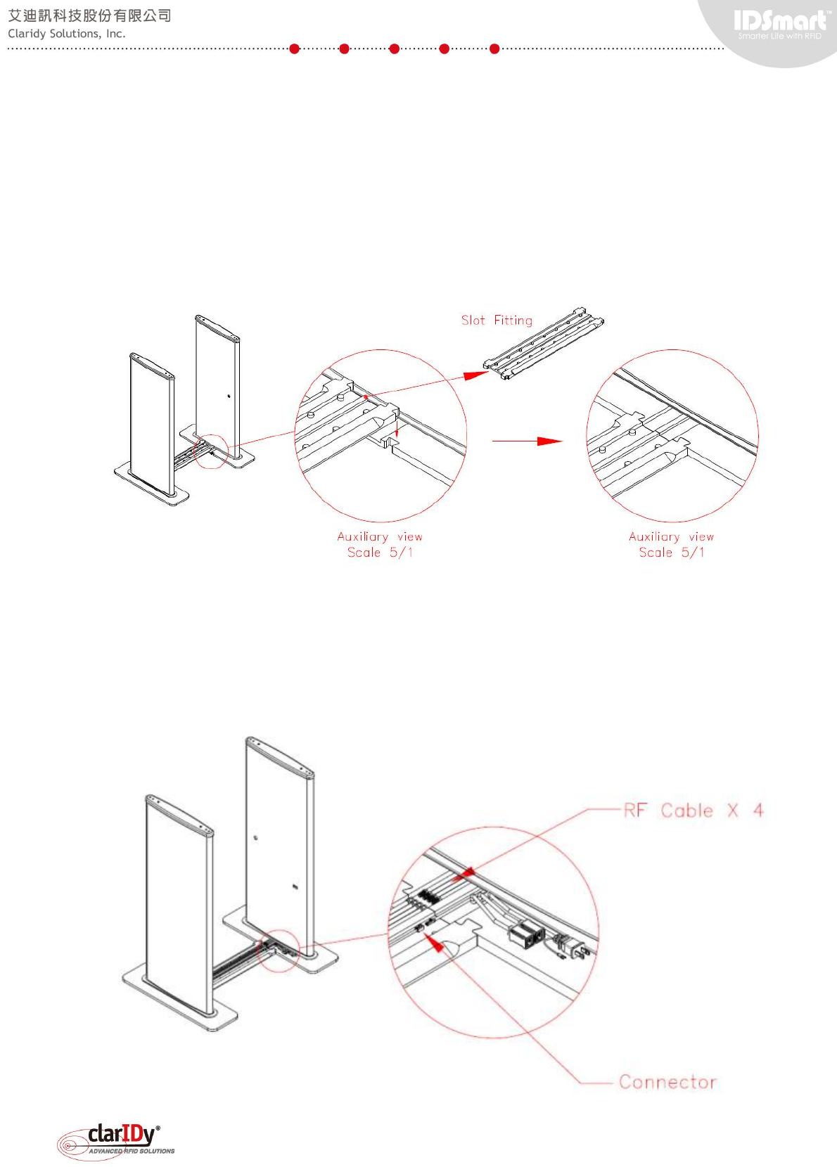
1.4.2. Connecting and Holding the Panels Together
Get the slot fitting part and snap one side to the secondary panel and the other side to the
main panel as illustrated below. The cables (not seen in the diagram below) should remain on
top of the mounting plate. By snapping both the mounting plate with the slot fitting, the main and
secondary panel are hold together and stand firmly on the floor.
1.4.3. Arranging and Wiring the Cables
After securing the panels on the floor, put the RF cables and signal cables on the slot.
Place RF cables together away from the signal cable. Connect the RF cables and the signal
cable by plugging the male plug to the female jack. Make sure that the RF cables are tightly
secured.
IDSmart UHF Security Gate User Manual
© Copyright 2014 ClarIDy Solutions, Inc. All rights reserved. 12/40
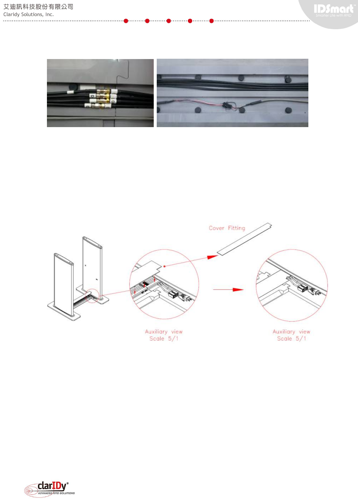
The RF cables are labeled with Channel "A" to "D", be sure that cable with the same
channel labeled are connected together. The signal connector is a fool-proof connector.
1.4.4. Covering Up the Slot Fitting
When the wiring is done, take the cover and slide it into the top area of the slot. The left
end of the cover has a small opening that allow Ethernet cable and power cable to go through.
In standard installation, power and Ethernet cable are within the equipment itself.
1.4.5 Switching On the Equipment
Ensure that proper power (115VAC for Model J, 230VAC for Model A & C) is supplied to
the equipment by plugging the power cable to the socket. The on/off switch is underneath the
lamp shade of the main panel to prevent tampering. Use a thin rod to push the switch to turn on
the power. When the equipment is ready, the blue LED light bar on top of the gate will be lit.
IDSmart UHF Security Gate User Manual
© Copyright 2014 ClarIDy Solutions, Inc. All rights reserved. 13/40
1.4.6 Preparation for Testing the Equipment
A notebook or computer with Ethernet adapter is required in order to setup the equipment
for testing. The default IP address of the equipment is set to 192.168.10.210 with subnet mask
of 255.255.255.0. Users are advised to set their notebook or computer Ethernet adapter to the
same network (i.e. 192.168.10.x). Then, plug one end of the Ethernet cable to the LAN
communication port of the equipment and the other end to the Ethernet adapter of the computer
or notebook. Follow instructions on section "1.5. Installation of the UHF Security Gate Tools" to
install the software tools to the notebook or computer.
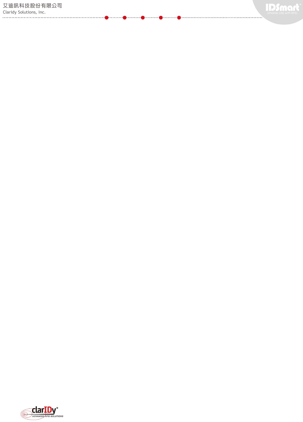
1.5. Installation of the UHF Security Gate Tools
The release media include installation package for UHF Security Gate Tools. These tools
are useful in verifying the security gate peripheral functionalities. To install the package, run
"setup.exe". Dependency packages such as .NET Framework and Visual C++ Runtime are
installed first following by the setup welcome screen. Proceed as instructed.
IDSmart UHF Security Gate User Manual
© Copyright 2014 ClarIDy Solutions, Inc. All rights reserved. 14/40
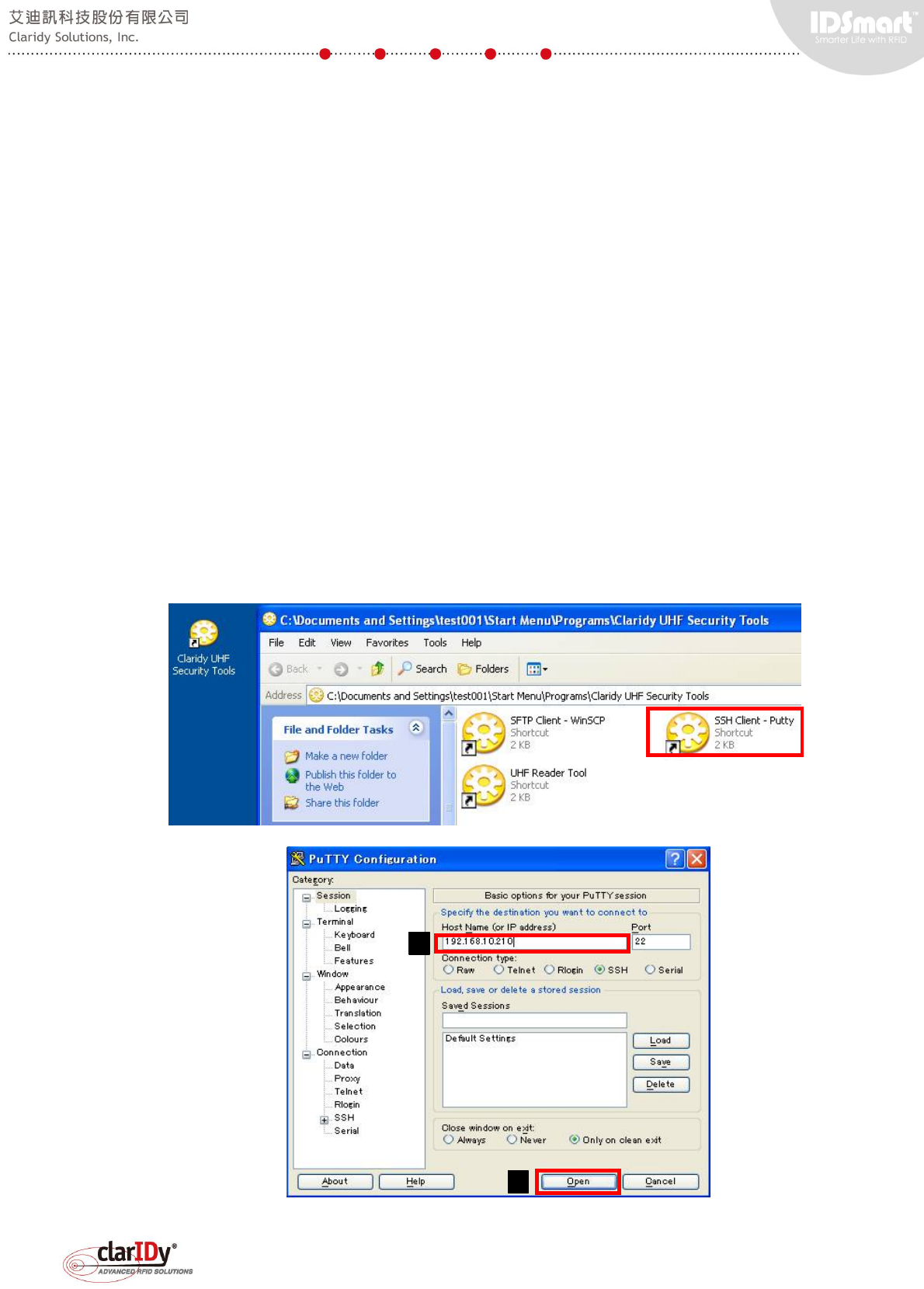
Upon completing the installation process, the system creates a shortcut named "UHF
Security Gate Tools" on the desktop.
The tools installed are WinSCP, Putty and UHF Reader Tool. These tools are used to
access the equipment in the upcoming section of the user manual.
Alternatively, users could also install their choice of ssh client or obtain tool pack that
doesn’t required installation from technical support.
1.6. SAFETY NOTES
The equipment can only be operated at the stated supply voltage. If the supply voltage is
too high, there is a risk of fire.
Always turn off power before performing any maintenance activities or touching any interior
part and exterior connection cables of the equipment. Failure to do so might lead to injuries.
There is a risk of health.
Appropriate means are provided to dissipate the heat generated within this equipment. The
equipment must however not be installed in a cabinet or on shelves with insufficient ventilation..
There is a risk of fire.
Protect the equipment from moisture, dripping water and spraying water. The equipment
must not be placed close to sources of heat, exposed to direct sunlight or operated in a damp
environment. The equipment may only be operated in the condition stated in the specification.
IDSmart UHF Security Gate User Manual
© Copyright 2014 ClarIDy Solutions, Inc. All rights reserved. 15/40
Do not place anything which has a naked flame on the equipment. There is a risk of fire.
Connection, installation and maintenance work, as well as all other work on the unit, may
only be carried out by properly qualified and trained personnel. Unauthorized changes to the
unit and the use of spare parts and peripheral devices which are not sold or recommended by
the manufacturer can result in fires, electric shocks and injuries. Such actions therefore result in
exclusion of liability and make the manufacturer’s warranty/guarantee null and void.
IDSmart UHF Security Gate User Manual
© Copyright 2014 ClarIDy Solutions, Inc. All rights reserved. 16/40
2. Deploying the Security Gate
Once the security gate has been installed in the designated area, most likely somewhere
near the exit, users may examine the functionality of the security gate by walking through the
gate with books that has been encoded.
The security gate can operate even without network connectivity. This design ensures
security policies continue to be enforced during network or server failure. The security gate will
trigger the alarm and switch to alert status if there is any book with security flag enabled. By
default, books returned to the library will have security flag enabled whereas books successfully
borrowed by patron will have security flag disabled. The security gate has blue light lit when it’s
in normal status. The security gate will trigger the alarm, which is the combination of buzzer
sound and red light flashing when it’s in alert status.
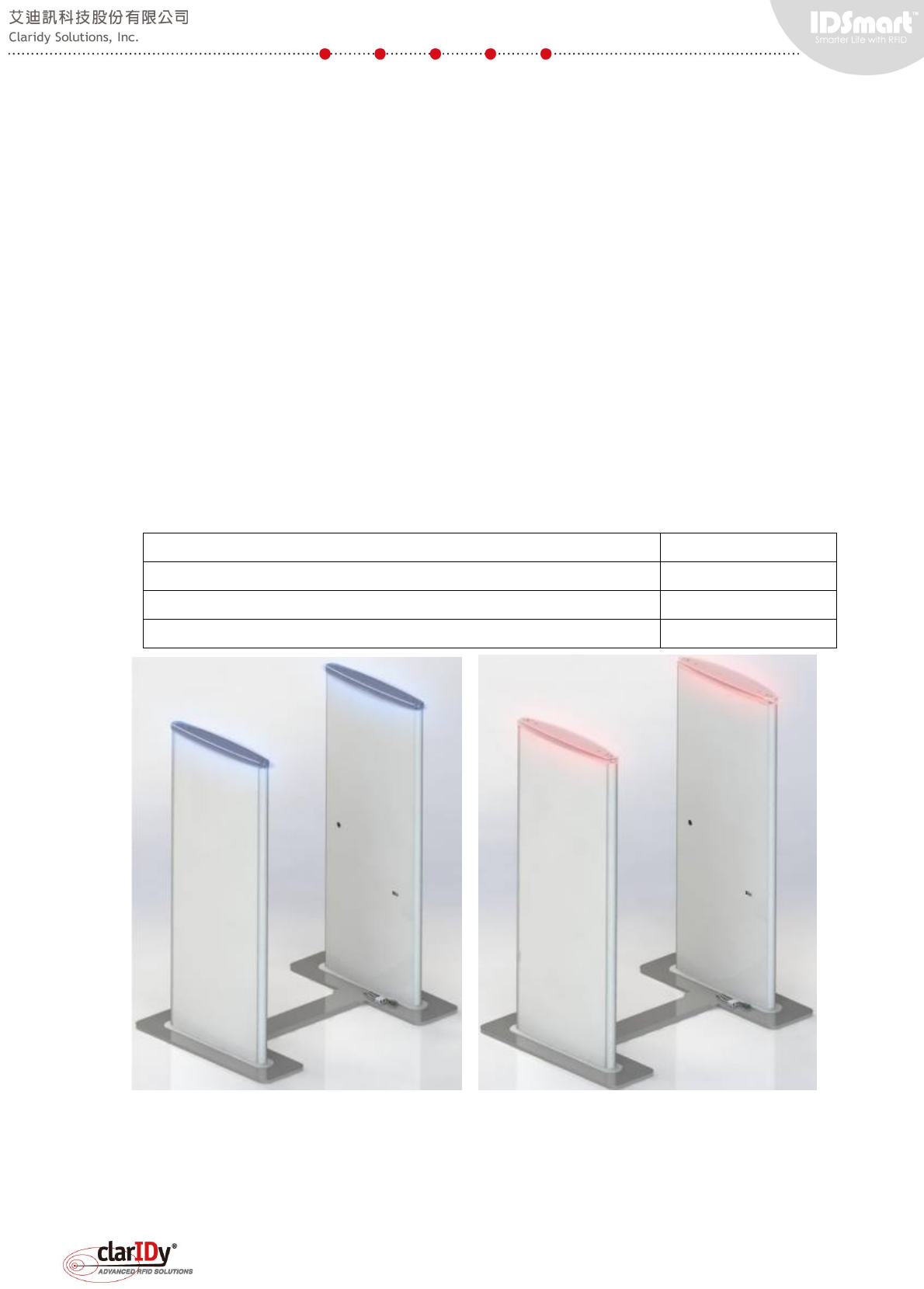
To validate the security gate, users can perform three basic scenarios below and check the
corresponding light and sound of the security gate.
Scenario Light and Sound
1. Walk through the gate without carrying any books Blue
2. Carry a book that has not been borrowed (security flag enabled)
Red with Buzzer
3. Carry a book that has been borrowed (security flag disabled) Blue
Security Gate Normal Security Gate Alert
If the security gate is not functioning as expected, users may perform diagnosis by
referring to steps in section 5. Testing the Component of the Equipment.
IDSmart UHF Security Gate User Manual
© Copyright 2014 ClarIDy Solutions, Inc. All rights reserved. 17/40
3. The System Connectivity
The system is configured to boot up automatically into embedded Linux. The blue LED light
bar will be turned on when the equipment is ready. The following section provides user with
more information regarding the configuration of the peripherals or components.
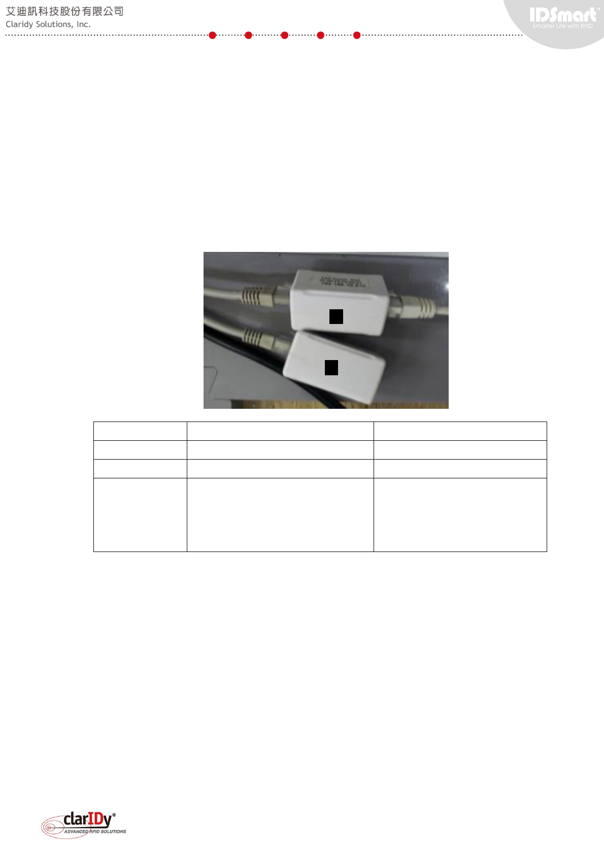
3.1. Ethernet Port
Two Ethernet port sockets are located at the lower part of the main panel. One of the port
is labeled as "Reader Setup Port" and the other is labeled as "LAN Comm. Port"
Reader Setup Port (Item #2) LAN Comm. Port (Item #1)
MAC Address 00:05:7B:82:02:5C 48:D8:FE:F0:00:01
IP Address 192.168.25.203 192.168.10.210
Usage Reserved for reader setup, debug
and testing only, not for application.
Connect to Local Area Network
for communication with other
system and remote access to the
system.
Both port are set to static IP address. The reader setup port doesn't need to be connected
to the network, it is only use for setup and tuning. The LAN communication port is the main
interface between the equipment and the network server or remote access client.
To make the equipment accessible for local area network, either adjust the network to
192.168.10.x or change the default IP address of the LAN Comm. Port. Refer to section 4.2.
Accessing and Changing the UHF Security Gate Network Configuration for information on how
to change IP address of the LAN Communication. Port.
Note: Users should not change the IP Address of the reader through the Reader
Setup Port. Changing the IP Address will disconnect the reader from the embedded
board. If user has accidentally change the IP address using the reader test tool. Use the
tool to search the reader and change it back to the default IP address.
1
2

IDSmart UHF Security Gate User Manual
© Copyright 2014 ClarIDy Solutions, Inc. All rights reserved. 18/40
3.2. LED Light Bar
The LED light bar is used primarily as warning indicators. To accommodate various
requirement, two type of LED light are available for control, namely Red and Blue. In general,
red lights represent warning/alert and blue lights represent normal condition. The LED lights are
control with different digital output of the embedded board, making it also possible to turn both
LED on simultaneously. In general application, either red or blue light are used at a single point
of time.
3.3. Buzzer
The buzzer is used together with the LED light to constitute the effect of alarm. Only on/off
control can be set.
3.4. Counter
The eight digits counter is used to record the amount of people that go through the gate.
The detection is normally done through IR sensor. The counter can also be reset
programmatically if there is special request. In general application, software counter is used
because software counter offers the flexibility of counting visitor within a period of time.
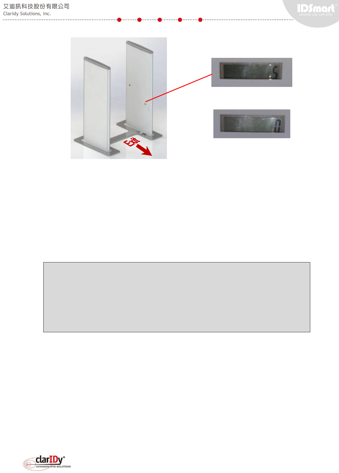
3.5. PIR Sensor and IR Sensor
The PIR sensor is meant to detect human motion that it faced within a distance of
approximately 2M. The IR sensor is meant to detect people walking through the equipment.
Both sensors can be used to trigger activity such as tag detection, alarm or counting.
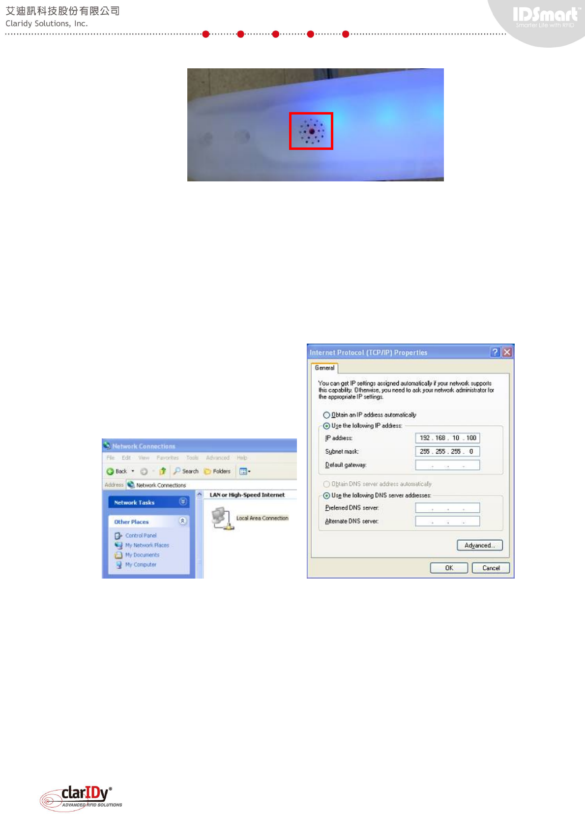
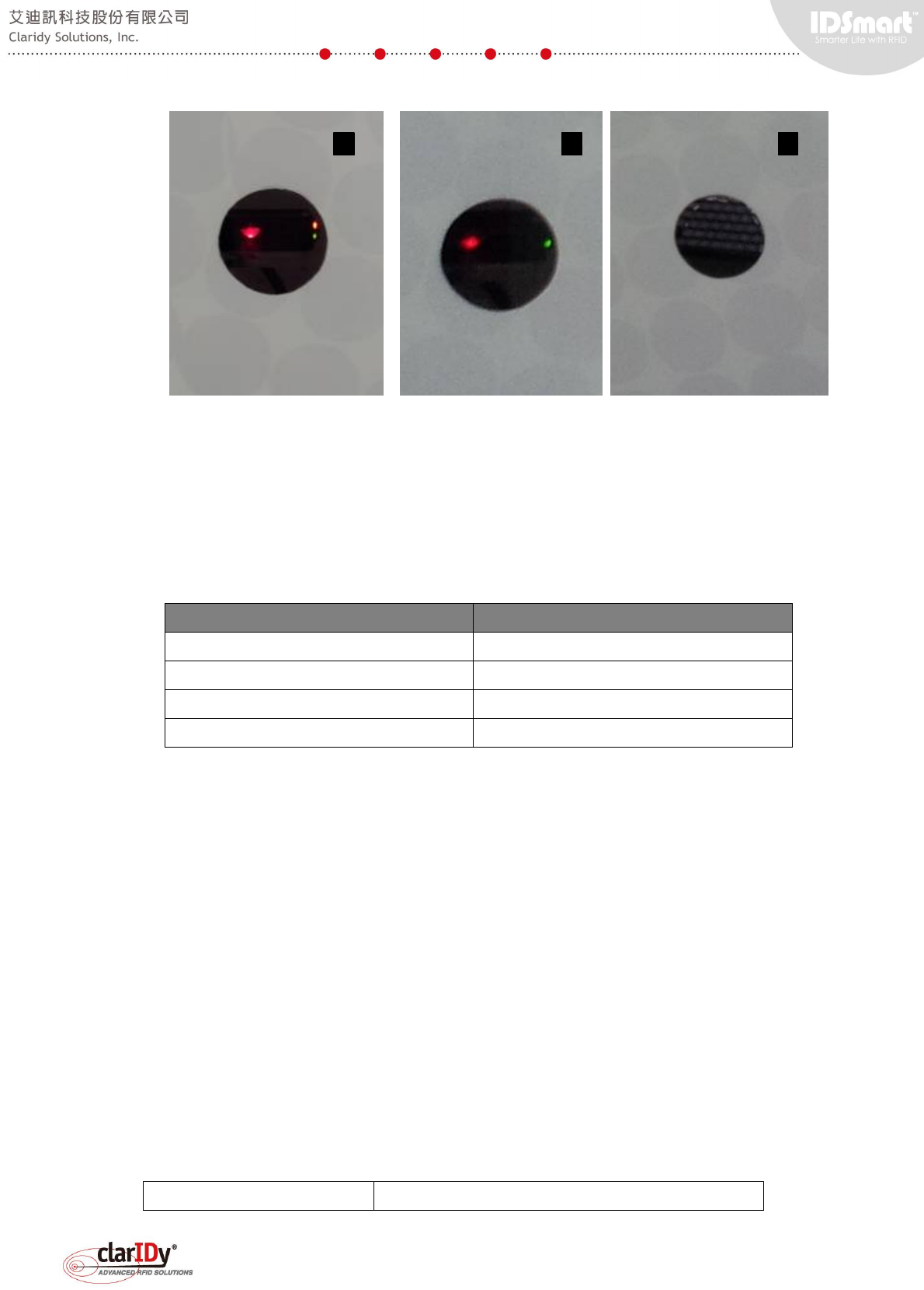
The IR sensor installed is retro-reflective type. A reflector is located at the other side of the
panel (image #3 as shown below). If an object or person comes in between of the IR sensor
and the reflector, the IR sensor signal is triggered. This can been determined by looking at the
orange LED light of the IR sensor. When there is nothing detected, the orange LED is off
(image #2).
IDSmart UHF Security Gate User Manual
© Copyright 2014 ClarIDy Solutions, Inc. All rights reserved. 19/40
3.6. UHF RFID Reader
The 16-port UHF RFID reader is conformed to EPC UHF Class 1 Gen 2 and capable of
supporting ISO18000-6C protocol. It is connected to the Ethernet interface of the embedded
board. The reader and the embedded board each has a fixed IP address assigned ensuring
direct communication between these two units..
Setting Value
Embedded Board Ethernet Port IP 192.168.25.210
Embedded Board Network Mask 255.255.255.0
UHF RFID Reader IP 192.168.25.203
UHF RFID Reader Network Mask 255.255.255.0
Note: User should not change the default IP address of the UHF RFID Reader.
Besides the internal Ethernet interface that connected to the Embedded Board. The
equipment also includes an external Ethernet Port (i.e. The Reader Setup Port) for
accessing the reader externally. This is particularly useful when user wish to calibrate
and tune the equipment for tag detection.
4. Modifying the Default Network Configuration
The security gate's network configuration (i.e. the configuration of LAN communication port)
can be changed by accessing the equipment through remote access terminal. SSH protocol is
selected for better security. This LAN communication port is the only port that user may change
according to the deployed networking environment.
4.1. Initial Network Configuration of UHF Security Gate
The factory default network configuration of the UHF Security Gate is as follows.
IP Address 192.168.10.210
1
2
3
IDSmart UHF Security Gate User Manual
© Copyright 2014 ClarIDy Solutions, Inc. All rights reserved. 20/40
Netmask 255.255.255.0
Gateway 192.168.10.253
Preferred DNS Server 8.8.8.8
Alternative DNS Server 8.8.4.4
4.2. Accessing and Changing the UHF Security Gate Network Configuration
There are two approaches to make the equipment accessible, either through changing the
network configuration of the equipment or the network configuration of the local area network.
Normally, changing equipment's network configuration is more feasible and practical. To
access the reader, please follow the steps below.
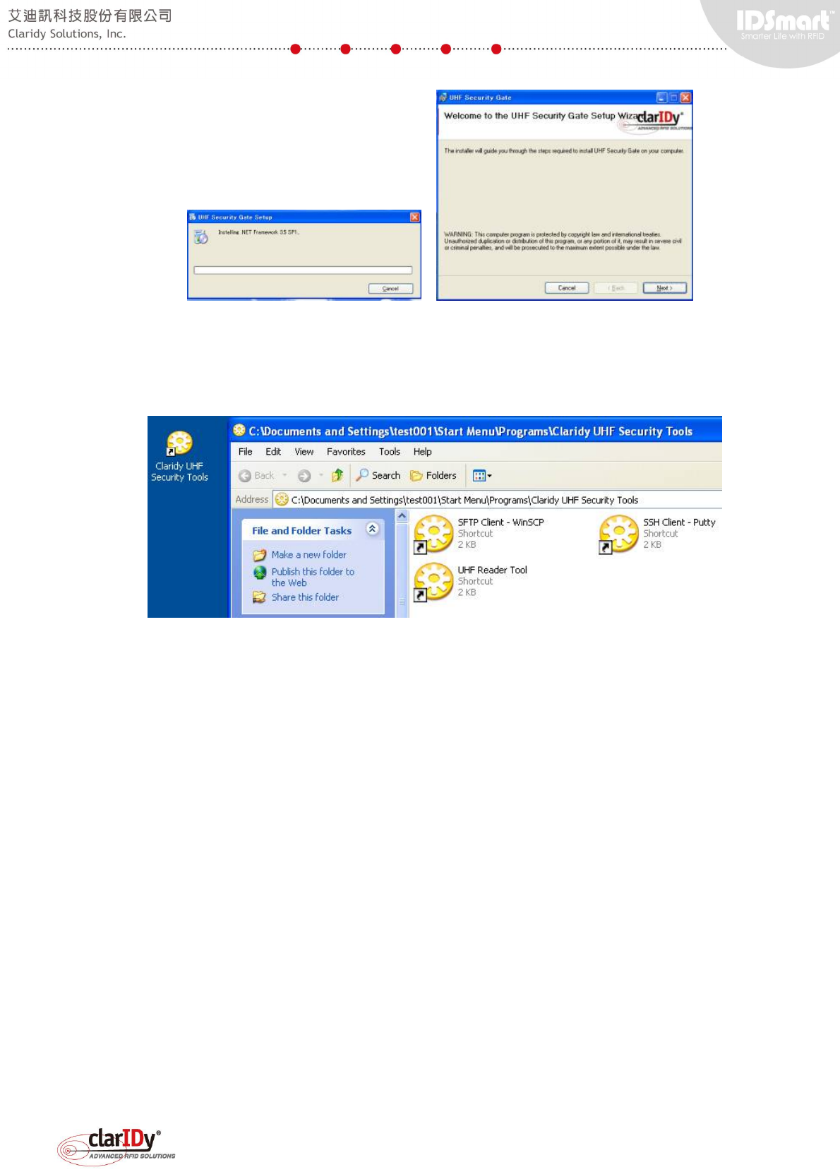
Prepare a Notebook or computer with Ethernet adapter.
Modify the network configuration with static IP and netmask. This will make the computer or
Notebook resides at the same network as the equipment.
IP Address 192.168.10.x (x can be any number between 1 to 252)
Netmask 255.255.255.0
Connect the Ethernet port of the computer or Notebook and UHF Security Gate "LAN
Comm. Port" with a standard cat 5 network cable.
Use SSH client to connect to the equipment. If this is the first time connecting to the
equipment, a security alert dialog pops up. Select "Yes" to continue. The username and
password to be used is as follows.
Username: sshuser
Password : IDSmart
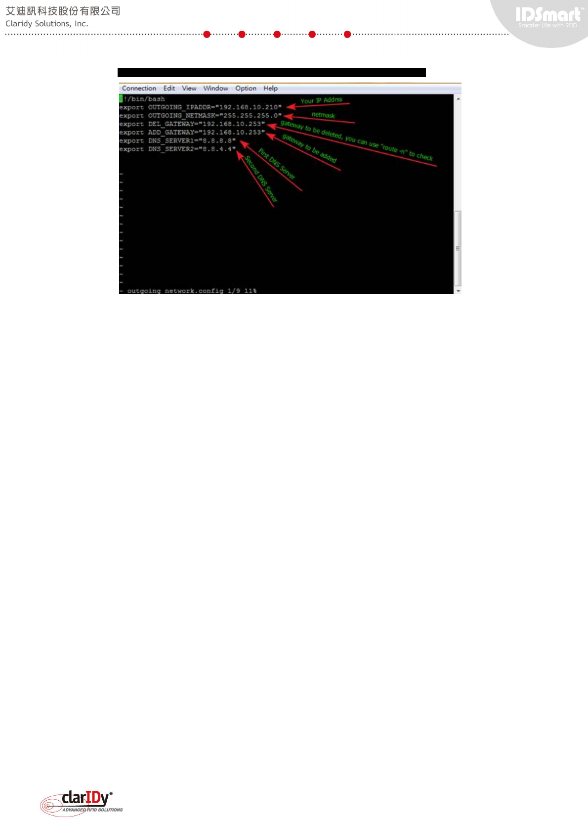
Modify "/home/sshuser/outgoing_network.config" to fit the current network
environment settings by typing "vi outgoing_network.config" at the command prompt.
This opens an editor window for changing the configuration.
IDSmart UHF Security Gate User Manual
© Copyright 2014 ClarIDy Solutions, Inc. All rights reserved. 21/40
sshuser@freescale ~$ vi outgoing_network.config
After finish editing the network configuration, type ":wq" to save the configuration file.
Restart or reboot the equipment.
Always remember the IP Address (OUTGOING_IPADDR) and the Subnet Mask
(OUTGOING_NETMASK) that are changed. When the equipment restarts, the remote access
will no longer available if the network of the notebook or computer are different from the
equipment. If for any reason users can no longer access remotely, the configuration can also
only be changed through accessing the system via console port. The console port can only be
connected through maintenance access of the equipment.
Gateway is used when the equipment communicates across different network. Be sure that
the DEL_GATEWAY and ADD_GATEWAY has the same address.
DNS_SERVER1 and DNS_SERVER2 must be set if the equipment is communicating with
other devices on the network using naming system instead of IP address.
5. Testing the Component of the Equipment
Once the equipment is ready, an illegal item such as an un-borrowed book will trigger
alarm when it is carry through the security gate. If the security gate is not function as expected,
users may switch to debug mode and perform diagnostic on each component during
troubleshooting.
The equipment is remotely accessed using SSH remote access software such as "Putty".
The remote access software should be installed on a computer. To simplify the testing process,
the remote access software can be installed on a notebook. A direct connection can be hooked
up between the notebook and the equipment using Ethernet cable without changing the
network configuration of the equipment (see section 1.4.6 Preparation for Testing the
Equipment).
IDSmart UHF Security Gate User Manual
© Copyright 2014 ClarIDy Solutions, Inc. All rights reserved. 22/40
The connection can only be made if the computer that has the remote access software
installed can reach the equipment.
Ping the equipment from the computer to ensure that network connectivity is OK. If it is
a direct connection, check cable if the equipment has no response.
Allow bi-directional access of port 22 as the equipment SSH protocol is configured to
listen and communicate through port 22. If it is a direct connection, check if there is any
antivirus or firewall security software that blocks this port when connection fails.
Consult the network administrator for further advice and information on the local area
network configuration. If the equipment and the computer is located on two different networks,
the gateway configuration of the equipment must be changed.
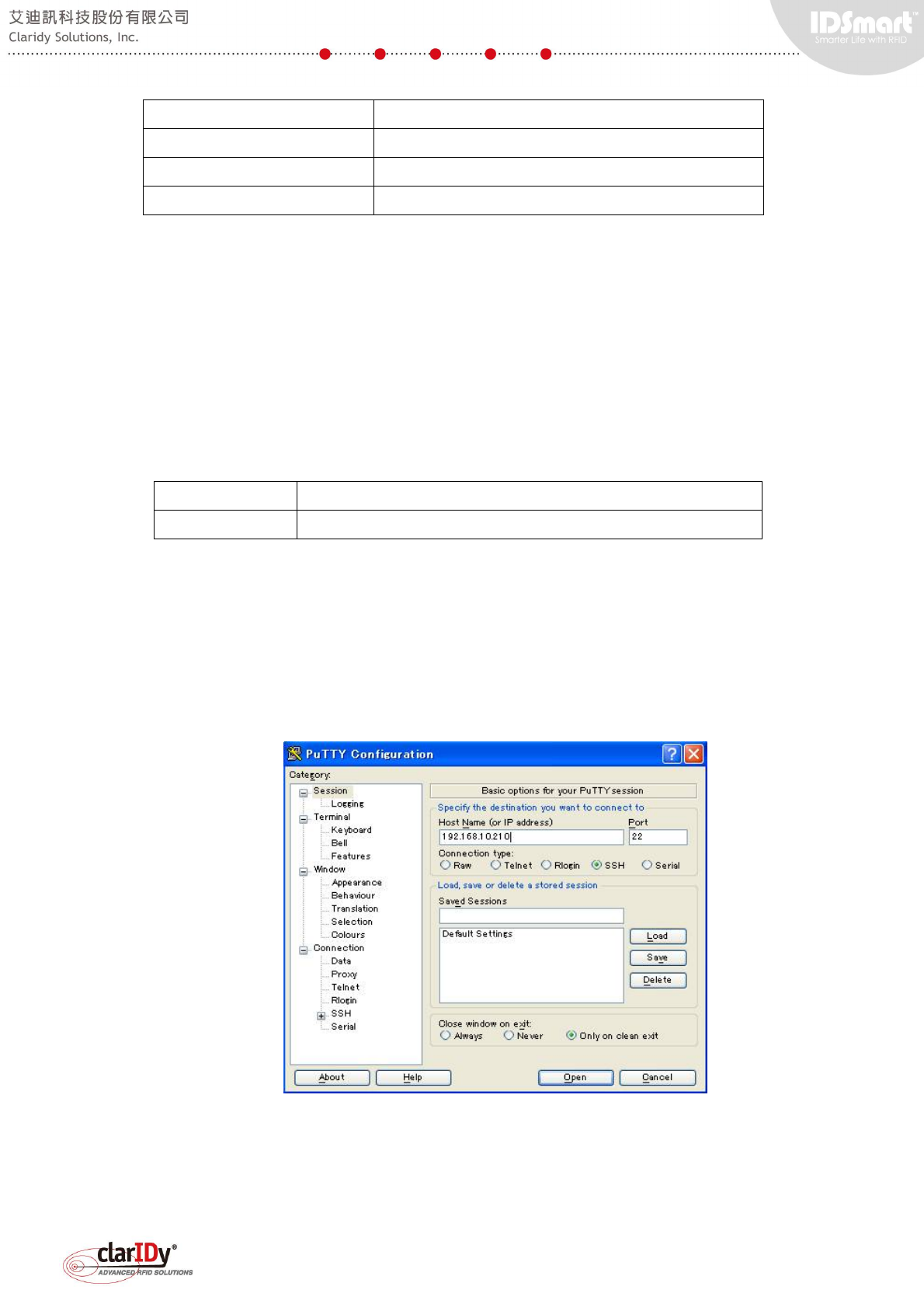
5.1. Connecting to the Equipment
Start the SSH remote access tool. "Putty" is used as the SSH remote access tool
throughout this user manual, users are free to choose different tool. Type the IP address of the
equipment in the "Host Name (or IP address)" textbox and click "Open" button.
1
2
IDSmart UHF Security Gate User Manual
© Copyright 2014 ClarIDy Solutions, Inc. All rights reserved. 23/40
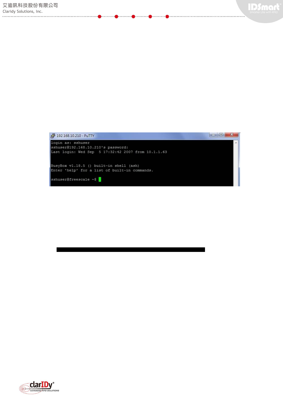
If this is a first time connection, a security alert will be shown. Choose "Yes" to accept the
security key for future connection, as we are pretty sure that we are connecting to the intended
equipment.
The default username and password is listed below. User can change the password with
Linux change password command once connected.
Username: sshuser
Password : IDSmart
A command shell is shown when the login is successful. Most of the common Linux
command works under this shell, but some may not since it is embedded Linux.
5.2. Switching to Debug Mode
The security gate is started up in service mode. To perform diagnostic, the user must
switch the security gate to debug mode.
After successful logged in with the "sshuser" account, user should be in the home directory
of the user, run the debug mode script by typing "./security-gate-DebugMode.sh" in the shell.
sshuser@freescale ~$ ./security-gate-DebugMode.sh
When the script executed, the security gate will reboot and user can log in to the system
running the debug mode. Always switch to debug mode when performing diagnostic and
configuration of the system.
The reboot process will kick the remote access connection so users will need to reconnect
to the system once the system restart. The LED light of the security gate will not turn to blue
after reboot to debug mode.
5.3. Running the Demo Program for Diagnosis
A demo program is developed to facilitate the testing of the equipment. The demo program
can test individual components of the equipment and is therefore very handy when performing
diagnosis. Before running the demo program, be sure that the system is in "debug mode".
The demo program is preinstalled in the equipment. It is located under the directory
"/usr/local/security-gate-demo/". When login, change the directory to "security-gate-demo" and
IDSmart UHF Security Gate User Manual
© Copyright 2014 ClarIDy Solutions, Inc. All rights reserved. 24/40
run the "./demo.sh" shell script.
sshuser@freescale ~$ cd /usr/local/security-gate-demo
sshuser@freescale /usr/local/security-gate-demo$ ./demo.sh
After executing the demo program, the context shell of the demo program is loaded. Type
"help" to see commands available for the demo program. Please refer to the SDK reference
manual for detailed usage.
sshuser@freescale ~$ cd /usr/local/security-gate-demo
sshuser@freescale /usr/local/security-gate-demo$ ./demo.sh
[Demo] Start Demo Program.
$>
$>help
[Demo] Commands ::
[Demo] Command Description
[Demo] "help" "Display all command and description"
[Demo] "connect" "Connect to CS468"
[Demo] "disconnect" "Disconnect from CS468"
[Demo] "inventory" "Start Inventory"
[Demo] "read-user-memory" "Read the user memory data"
[Demo] "read-tid" "Read the TID data"
[Demo] "stop" "Stop Operation"
[Demo] "set-power" "Set the antenna power."
[Demo] "get-power" "Get the antenna power."
[Demo] "enable-ant" "Enable the antenna port"
[Demo] "disable-ant" "Disable the antenna port"
[Demo] "set-fix-q" "Set Fix-Q Algorithm"
[Demo] "set-dwell-time" "Set the dwell time of the antenna"
[Demo] "set-ant-inv-count" "Set the inventory round counts of the antenna"
[Demo] "start-scenario" "Run Scenario"
[Demo] "stop-scenario" "Stop Scenario"
[Demo] "get-ir-state" "Get the state of the IR pin (0 or 1)"
[Demo] "start-ir" "Start monitor the IR pin state."
[Demo] "stop-ir" "Stop monitor the IR pin state"
[Demo] "get-pir-state" "Get the state of the PIR pin (0 or 1)"
[Demo] "start-pir" "Start monitor the PIR pin state."
[Demo] "stop-pir" "Stop monitor the PIR pin state"
[Demo] "turn-red-led-on" "Turn red led on"
[Demo] "turn-red-led-off" "Turn red led off"
[Demo] "blink-red-led" "Blink the red led"
[Demo] "turn-blue-led-on" "Turn blue led on"
[Demo] "turn-blue-led-off" "Turn blue led off"
[Demo] "blink-blue-led" "Blink the blue led"
[Demo] "add-counter" "Add counter by 1"
[Demo] "reset-counter" "Reset counter "
[Demo] "beep" "Make beep."
[Demo] "trigger-alarm" "Trigger Alram."
[Demo] "turn-reserved-port-on" "Turn on the reserved port."
[Demo] "turn-reserved-port-off" "Turn off the reserved port"
[Demo] "q" "quit "
$>
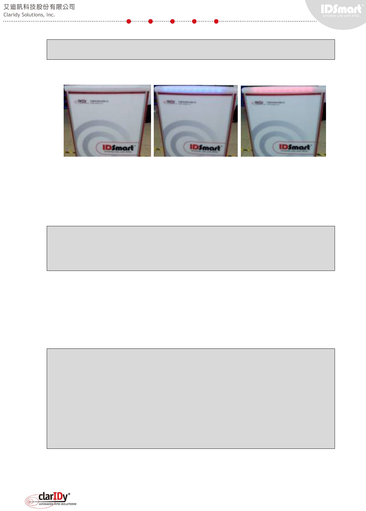
5.4. LED Light Bar Verification
The two-color LED light bar can be controlled separately. The following example turns the
blue LED off and turn the red LED on. The blink function allows user to blink the LED light bar
for a desired time in seconds. The example also makes the red LED blink for 5 seconds.
[Demo] Start Demo Program.
$>
$>turn-blue-led-off
[Demo] Turn Blue led off
$>turn-red-led-on
[Demo] Turn the red led on
IDSmart UHF Security Gate User Manual
© Copyright 2014 ClarIDy Solutions, Inc. All rights reserved. 25/40
$>blink-red-led 5
[Demo] Blink red led :: "5" seconds
$>
From left to right: Both LED lights are off, blue LED lights on, red LED lights on.
5.5. Buzzer and Alarm Triggering
Users can control the number of second that a buzzer beeps. By combining the buzzer
beeping and red LED light bar blinking, alarm effect can be created. The example causes the
buzzer to beep for 7 seconds and then sound the alarm for 3 seconds (red lights and buzzer will
be activated for 3 seconds).
[Demo] Start Demo Program.
$>
$>beep 7
[Demo] Beep in "7" seconds
$>trigger-alarm 3
[Demo] Trigger alarm in "3" seconds
$>
5.6. Counter
Users may increase the counting or reset the counting of the counter. The following
example increases the counter five times and then reset it. The counter current count can be
checked by looking at the lower part of the main panel. The reset counter is per request special
feature which might not available for most model.
[Demo] Start Demo Program.
$>
$>add-counter
[Demo] Plus 1 in the Counter
$>add-counter
[Demo] Plus 1 in the Counter
$>add-counter
[Demo] Plus 1 in the Counter
$>add-counter
[Demo] Plus 1 in the Counter
$>add-counter
[Demo] Plus 1 in the Counter
$>
$>reset-counter
[Demo] Reset the Counter
$>
IDSmart UHF Security Gate User Manual
© Copyright 2014 ClarIDy Solutions, Inc. All rights reserved. 26/40
Current count at 5
After reset of counter
5.7. PIR Sensor and IR Sensor
Both sensors are input to the system, which mean that they are triggered by external event.
The sensors are put to monitoring the external event, which is people coming near the
equipment or passing through the equipment.
To make the testing straight forward, the buzzer beeps once when the sensors are
triggered. Due to the nature of fast sensor response, the sensor response are deliberately
slowed down through software programming so that the equipment is not over reacted or too
sensitive to motion. The following example starts the PIR sensor monitoring process and stop it
[Demo] Start Demo Program.
$>
$>start-pir
[Demo] Start Monitor the PIR
$>[Demo] PIR Detected
[Demo] PIR Detected
[Demo] PIR Detected
[Demo] PIR Detected
$>
$>stop-pir
[Demo] Stop Monitor the PIR
$>
When PIR sensor monitoring process started, stand in front of the equipment and move
around (e.g. walk toward the gate). When the PIR sensor detects the motion, the buzzer's beep
can be heard. Once detected, the PIR sensor stop detecting until one second later.
IDSmart UHF Security Gate User Manual
© Copyright 2014 ClarIDy Solutions, Inc. All rights reserved. 27/40
The following example starts the IR sensor monitoring process and stop it
[Demo] Start Demo Program.
$>
$>start-ir
[Demo] Start Monitor the IR
$>[Demo] IR Detected
[Demo] IR Detected
[Demo] IR Detected
[Demo] IR Detected
$>
$>stop-ir
[Demo] Stop Monitor the IR
$>
When IR sensor is started, walk through the security gate. The buzzer beeps when the
user passes through the IR sensor.
5.8. UHF RFID Reader Verification
The reader is connected internally to the embedded board through Ethernet port. The
IDSmart UHF Security Gate User Manual
© Copyright 2014 ClarIDy Solutions, Inc. All rights reserved. 28/40
reader is assigned a static IP address and connected to a designated IP address of the
embedded board. User should not change this IP address as they are private internal IP
address. The internal IP address of the UHF reader is set to 192.168.25.203. The following
example starts a reader connection and set the Q value parameter of the reader. Q value is one
of many parameters of UHF EPC C1G2. The parameters can be adjusted based on various
scenario, this is out of the scope of this user manual. Consult RFID technical expert for
optimization of these values. Connection to the reader is required before performing any
inventory or tag reading operation.
[Demo] Start Demo Program.
$>
$>connect 192.168.25.203
[Demo] Connect to the Reader. IP : "192.168.25.203"
[Demo] CS468 Connected!!
[Demo] Initial the default parameters.
[Demo] Disable 0-port antenna and enable the 8 ~ 15 port antenna.
[Demo] Set dwell time as 250
[Demo] Set antenna power as 270
$>
$>set-fix-q
[Demo] Error :: The count of parameters is not match with the command. CMD:: "set-fix-q"
[Demo] Usages ::
"set-fix-q [q-value] [retry-count] [toggle] [runTillZero]"
$>
$>set-fix-q 4 0 1 1
[Demo] Set Fix Q : 4 ,Retry Count : 0 , is Toggle : true , is Run Till Zero : true
$>
Prepare several books with tag or UHF RFID tag and place those tags near the equipment.
Depending on the environment, the reading radius could be around one to two meters. To test
the reader, we place the UHF RFID tags in between the two panels of the security gate. The
following example performs an inventory cycle. Information of tags, i.e. PC, EPC and RSSI of
the detected tags are displayed, regardless of whether it repeats on different antenna.
$>
$>set-fix-q 4 0 1 1
[Demo] Set Fix Q : 4 ,Retry Count : 0 , is Toggle : true , is Run Till Zero : true
$>
$>inventory
[Demo] Start Inventory
[Demo] Tag PC:: "4800" EPC :: "104000000001023a80000003525c00010000" , RSSI :: "66.4"
[Demo] Tag Detected
[Demo] Tag PC:: "4800" EPC :: "104000000001023a80000003525c00010000" , RSSI :: "60"
[Demo] Tag Detected
[Demo] Tag PC:: "4800" EPC :: "104000000001023a80000003525c00010000" , RSSI :: "64"
[Demo] Tag Detected
[Demo] Tag PC:: "4800" EPC :: "104000000001023a80000003525c00010000" , RSSI :: "61.6"
[Demo] Tag Detected
[Demo] Tag PC:: "4800" EPC :: "104000000001023a80000003525c00010000" , RSSI :: "62.4"
[Demo] Tag Detected
[Demo] Tag PC:: "4800" EPC :: "104000000001023a80000003525c00010000" , RSSI :: "62.4"
[Demo] Tag Detected
[Demo] Tag PC:: "4800" EPC :: "104000000001023a80000003525c00010000" , RSSI :: "76.8"
[Demo] Tag Detected
[Demo] Tag PC:: "4800" EPC :: "104000000001023a80000003525c00010000" , RSSI :: "76.8"
[Demo] Tag Detected
[Demo] Tag PC:: "3000" EPC :: "300833b2ddd9014000000000" , RSSI :: "50.4"
[Demo] Tag Detected
[Demo] Tag PC:: "3000" EPC :: "300833b2ddd9014000000000" , RSSI :: "48.8"
[Demo] Tag Detected
IDSmart UHF Security Gate User Manual
© Copyright 2014 ClarIDy Solutions, Inc. All rights reserved. 29/40
[Demo] Tag PC:: "4800" EPC :: "104000000001023a80000003525c00010000" , RSSI :: "73.6"
[Demo] Tag Detected
[Demo] Tag PC:: "4800" EPC :: "104000000001023a80000003525c00010000" , RSSI :: "67.2"
[Demo] Tag Detected
[Demo] Tag PC:: "4800" EPC :: "104000000001023a80000003525c00010000" , RSSI :: "74.4"
[Demo] Tag Detected
[Demo] Tag PC:: "4800" EPC :: "104000000001023a80000003525c00010000" , RSSI :: "76"
: (truncated)
:
$>
There are eight antenna (port 8 to port 15) installed for the equipment, to set antenna
power and dwell time, run the command with appropriate parameter, check the SDK reference
manual for further usage. The following example disables antenna on port no.8 and enables it.
Then, a disconnection to the reader is done follows by exiting the context shell.
Note: only one connection can be connected to the reader at the same time.
$>
$>disable-ant 8
[Demo] Disable Antenna :: 8
$>
$>enable-ant 8
[Demo] Enable Antenna :: 8
$>
$>disconnect
$>
$>q
sshuser@freescale ~/security-gate-demo$
5.9. Switching to Service Mode
Once the user has completed the diagnosis, the system should be switched to service
mode. The service mode script is located in the home directory of the "sshuser". Change the
directory to "/home/sshuser". the run the debug mode script by typing
"./security-gate-DebugMode.sh" in the shell.
sshuser@freescale /usr/local/security-gate-demo$ cd /home/sshuser
sshuser@freescale ~$ ./security-gate-ServiceMode.sh
When the script executed, the security gate will reboot and switch to service mode. Always
switch to debug mode when performing diagnostic and configuration of the system. In service
mode, the security gate LED will be red when restarting and turn to blue when it is ready to
service. If the LED doesn’t switch from red to blue within 20sec, login to the system again to
correct the issue.
6. Accessing the UHF RFID Reader with Security Gate Tools
The UHF RFID Reader is internally connected to the embedded board. To facilitate testing
and tuning, the security gate tools include a program that can directly connect to the reader
through the Ethernet Port labeled "Reader Setup Port". This tool is especially useful when
developers wish to test different setting of the reader and antenna to optimize the result of the
IDSmart UHF Security Gate User Manual
© Copyright 2014 ClarIDy Solutions, Inc. All rights reserved. 30/40
security gate detection. One of the key successful factors of UHF RFID equipment deployment
is environment. This tool provides a way to easily perform on site tuning with portable computer
such as Notebook.
6.1. Prerequisite of using the UHF Reader Tool
Before using the tool, install the tool to the computer according to the instructions
described in section 1.5. Installation of the UHF Security Gate Tools.
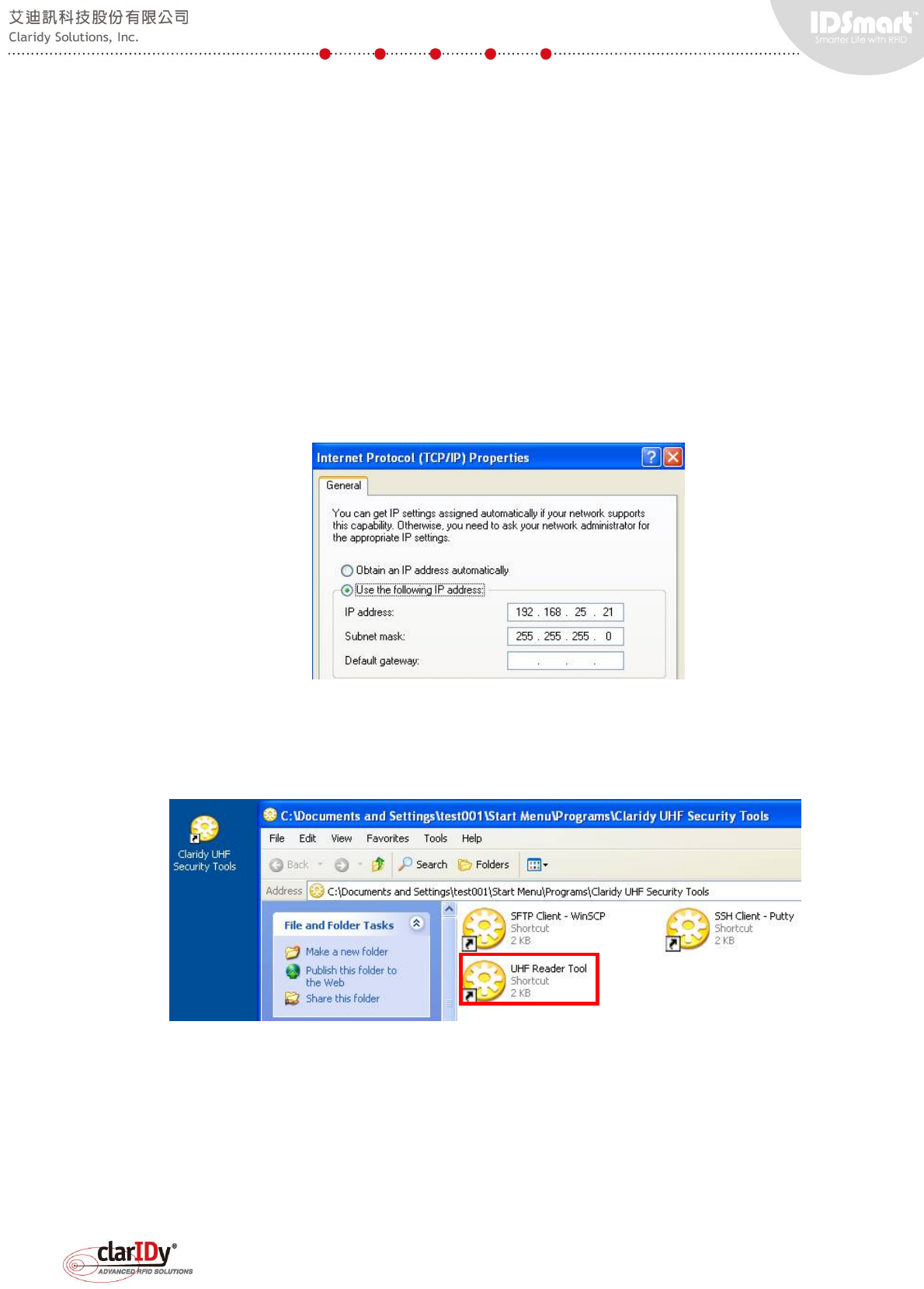
The computer Ethernet interface configuration will need to be changed to ensure the
computer residing on the same network as the UHF RFID reader. The reader has a static IP
address of 192.168.25.203 and subnet mask of 255.255.255.0. As a result, the IP address of
the computer should be set to 192.168.25.X (except 192.168.25.0 and 192.168.25.203) with
the same subnet mask. The following example set the computer IP address to 192.168.25.21
6.2. Connecting to the UHF RFID Reader
Double click "Claridy UHF Security Gate Tools" shortcut on the desktop and double click
the "UHF Reader Tool" shortcut to run the tool.
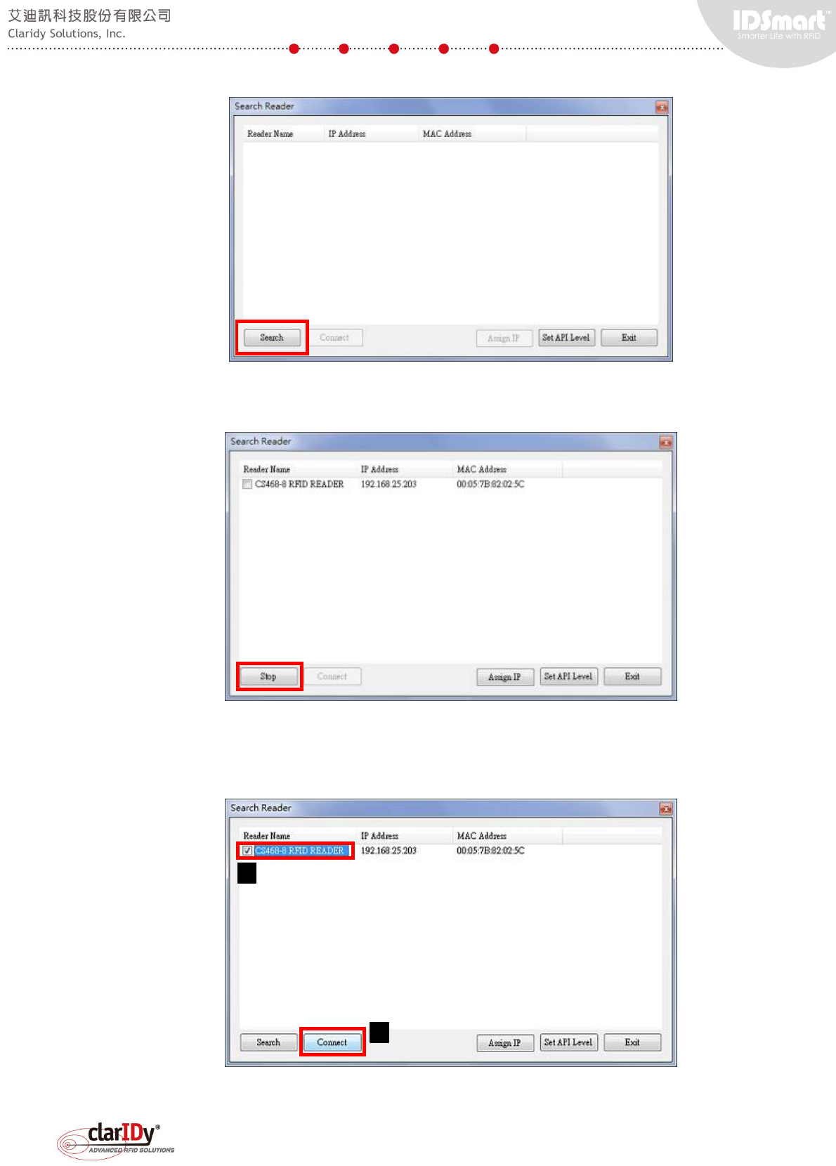
An initial search dialog is presented when the program is executed. Click "Search" button
to discover the reader. Since the UHF RFID reader and the computer are allocated to the same
network, the discovery process is pretty straight forward.
IDSmart UHF Security Gate User Manual
© Copyright 2014 ClarIDy Solutions, Inc. All rights reserved. 31/40
After searching the network, the installed UHF RFID reader at 192.168.25.203 is found.
Stop the search by clicking the "Stop" button.
Check the checkbox next to the reader name and click "Connect" button to connect to the
reader. A splash screen will be shown while the program attempts to access the UHF RFID
reader.
1
2
IDSmart UHF Security Gate User Manual
© Copyright 2014 ClarIDy Solutions, Inc. All rights reserved. 32/40
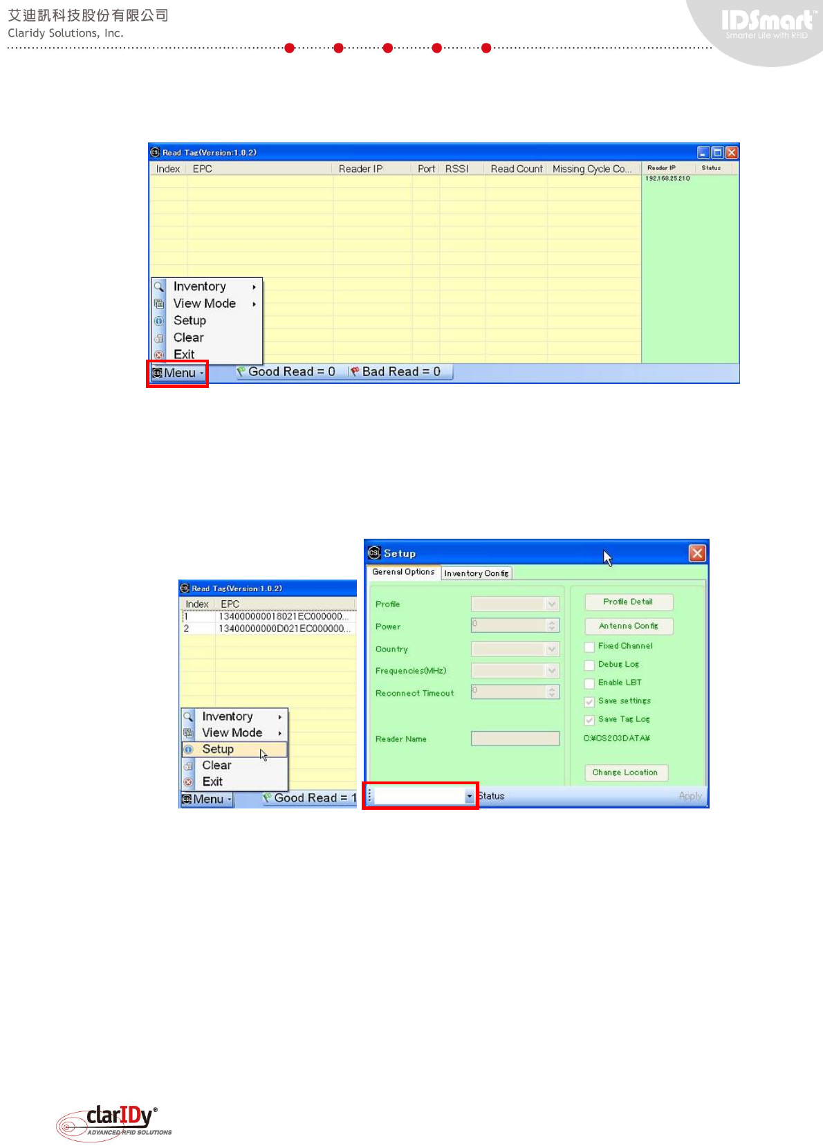
After connected to the reader. Users may choose the intended operation using the "Menu"
located at the lower left corner.
6.3. Configuring the UHF RFID Reader and Antenna Settings
To configure the UHF RFID reader, select "Setup" from the "Menu". The setup dialog pops
up showing various parameters that can be refined. To start configuring the UHF RFID reader,
select the IP address of the UHF RFID reader by clicking the combo box located at the lower
left corner of the dialog.
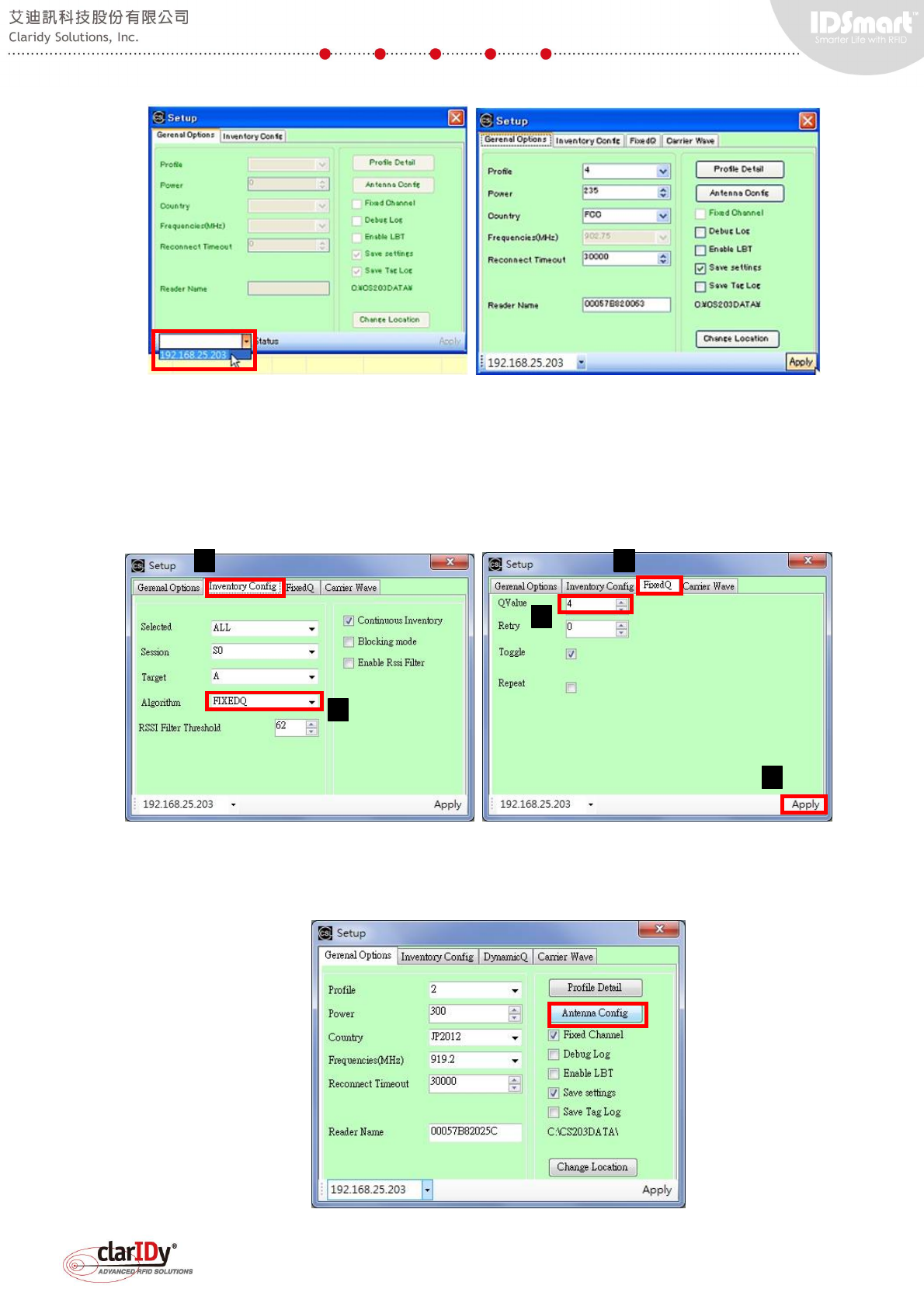
After choosing the designated UHF RFID reader. The configuration tabs and options are
enabled with additional FixedQ and Carrier Wave tabs available for access.
IDSmart UHF Security Gate User Manual
© Copyright 2014 ClarIDy Solutions, Inc. All rights reserved. 33/40
The general options tab allows setting of profile, power, country regulation and reconnect
timeout of the UHF RFID reader. The following example setup the reader to adopt Fixed Q
algorithm with a Q value of 4. After changing the value of the setting, remember to click the
"Apply" button located at the lower right corner.
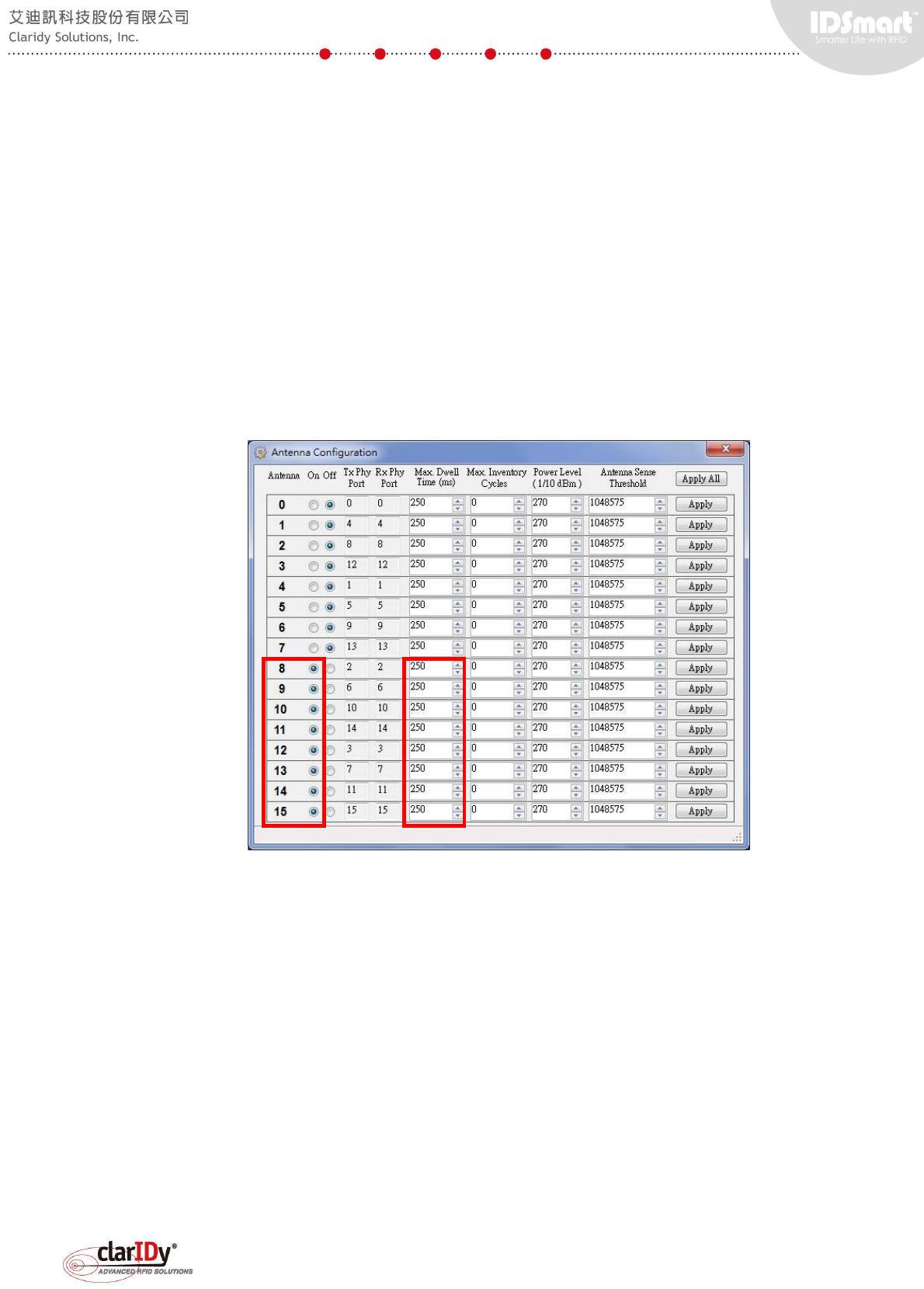
Antenna configuration can be accessed and set by clicking "Antenna Config" button in the
general options tab.
1
2
3
4
5
IDSmart UHF Security Gate User Manual
© Copyright 2014 ClarIDy Solutions, Inc. All rights reserved. 34/40
This equipment's UHF RFID reader is capable of controlling 16 antenna ports. Only 8
antenna ports (Port 8 to 15) are attached to antenna for this equipment. The tool automatically
enables port 8 to 15 and disables port 0 to 7 when "Antenna Config" is executed for the first
time. Users may configure the Dwell time, Inventory Cycle and Power Level of each antenna
port. Click "Apply" button to apply setting to a single antenna port. Click "Apply All" to apply
setting to all antenna ports according to what configured on the screen. The Antenna can be
switched on and off by clicking the corresponding radio button. The following configuration will
allow the equipment to scan through 8 antennas in 2 seconds as the dwell time for each
antenna port is 250ms.
Further adjustment can be done. The tool is handy for experimenting with different setting
of the equipment. Check the result of the setting by doing an inventory cycle.
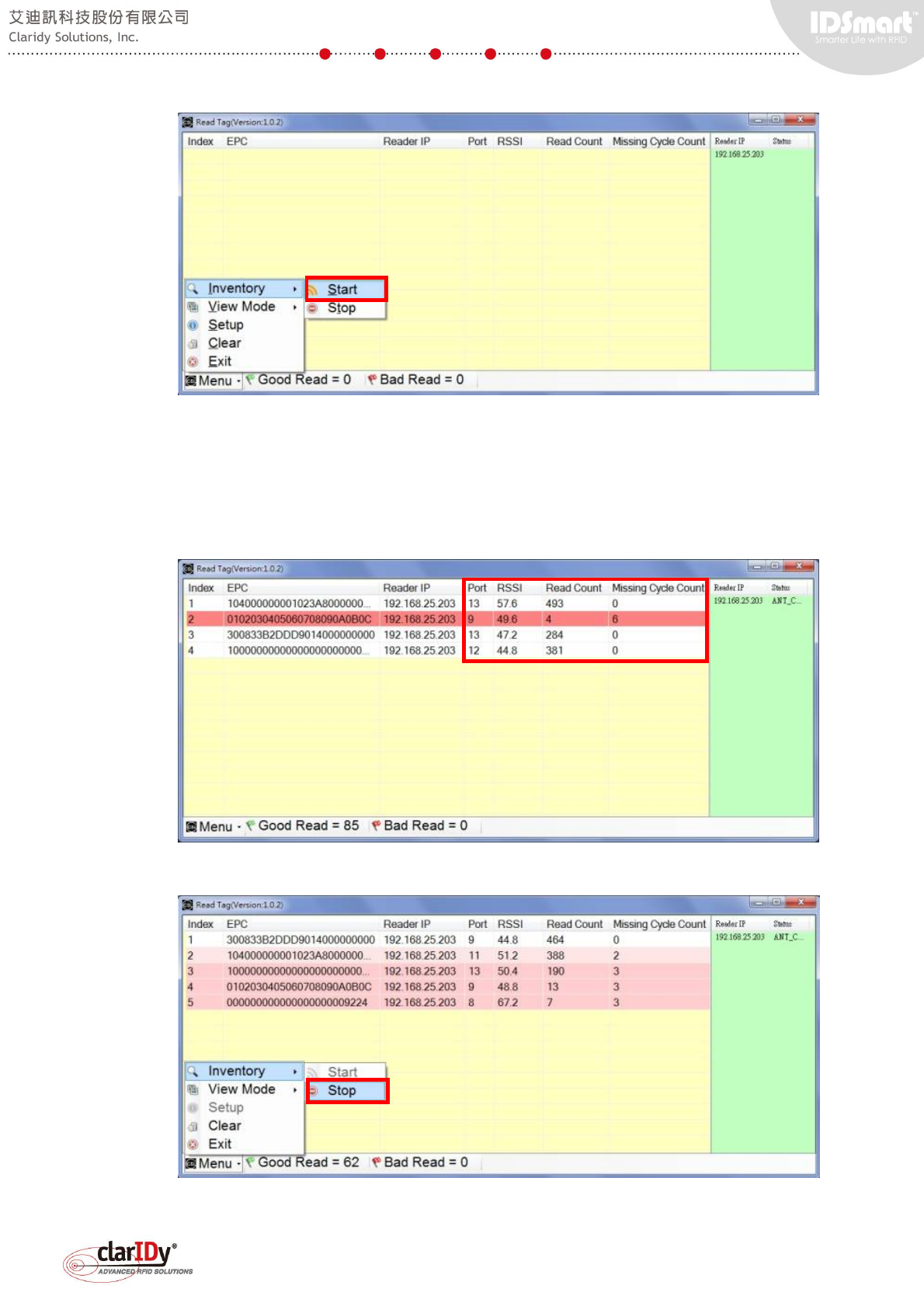
6.4. Performing Inventory Operation
After setting up the desired value for the reader and antenna ports, users can then check
the result by performing inventory operation through the tool. Start the inventory operation by
selecting "Start" under the "Inventory" sub menu.
IDSmart UHF Security Gate User Manual
© Copyright 2014 ClarIDy Solutions, Inc. All rights reserved. 35/40
Place tags near to the equipment and the detected tag information shall display on the grid.
Port, RSSI, Read Count and Missing Cycle Count can be used to determine the effect of the
parameter set for the reader and antenna ports.
Stop the inventory by selecting "Stop" under the "Inventory" sub menu.
Select "Exit" from the menu if users wish to end current connection with the reader. Note
IDSmart UHF Security Gate User Manual
© Copyright 2014 ClarIDy Solutions, Inc. All rights reserved. 36/40
that only one connection can be made to the reader at the same time.
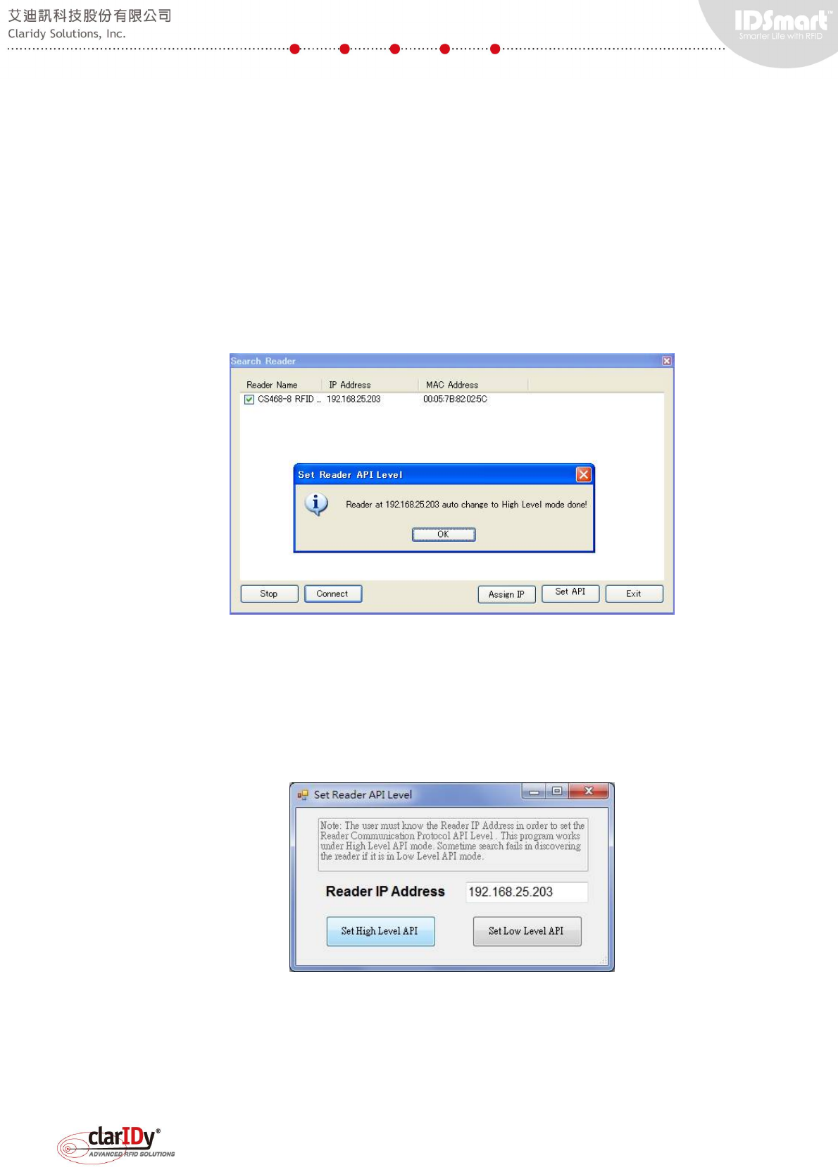
6.5. Setting the API Level of the UHF RFID Reader
The UHF RFID reader has two modes when it comes to API. The demo program provided
with the equipment uses low level API to communicate with the reader. Whereas, the UHF
reader tool uses high level API to communicate with the reader. When connecting to the reader
using the UHF reader tool, the tool automatically checks the mode of the API. The tool
automatically switches to high level API mode if it finds that the reader is in low level API mode.
A message box pops up if automatic switching of low level to high level API occurs. Click "OK"
button to proceed if the message box pops up.
Always check the networking configuration and Ethernet cable when attempting to find the
UHF RFID Reader. If the tool cannot connect to the reader after a period of time, user could try
to switch API level manually by clicking on the "Set API" button on the search reader dialog.
The set API level can only be performed when a reader has been successfully searched. Select
"Set High Level API" button to switch the reader to high level API mode.
IDSmart UHF Security Gate User Manual
© Copyright 2014 ClarIDy Solutions, Inc. All rights reserved. 37/40
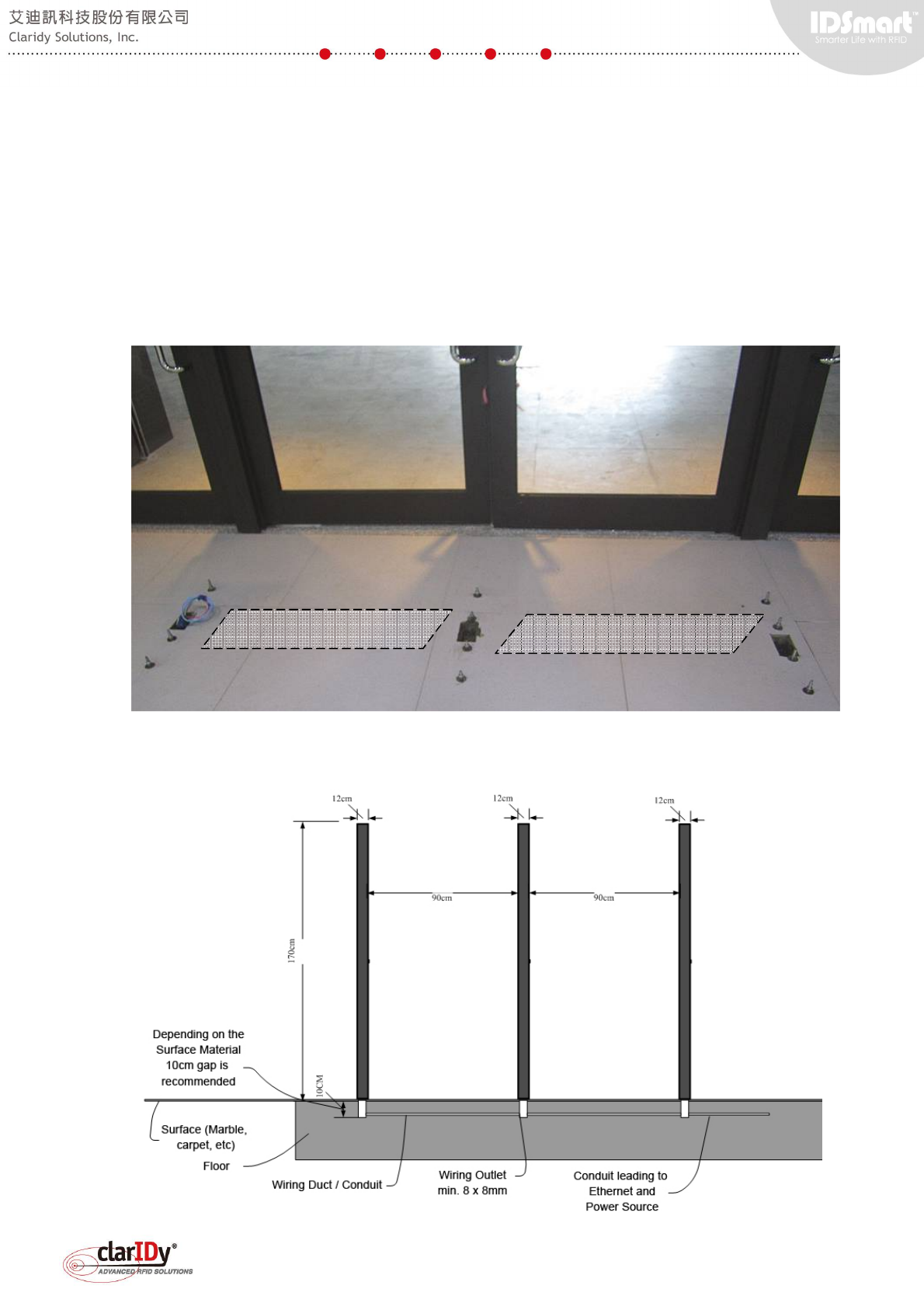
7. Appendix - Security Gate Mounting
In general, the security gate is best mounted to the floor for robustness and aesthetic. If
base plate or mounting plate approach is desired, installers are responsible for designing the
base plate or mounting plate according to the site survey. Consult Claridy technical personnel
for customizing the base plate or mounting plate. The following picture illustrates the mounting
point for the gate which ensure the panel of the security gate is correctly aligned. Wiring conduit
or duct is located underneath the floor surface.
The diagram below illustrates three panels of a double lane security gate mounted to the
floor.
Conduit or duct underneath
Conduit or duct underneath
IDSmart UHF Security Gate User Manual
© Copyright 2014 ClarIDy Solutions, Inc. All rights reserved. 38/40
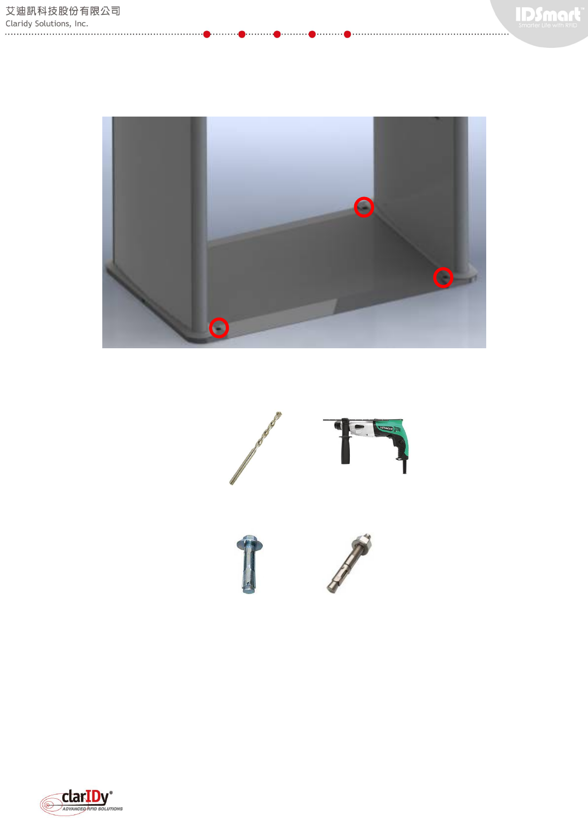
The following base plate or mounting plate is one of many types available for shipping.
There are 4 holes (3 visible and shown below) designed for mounting the security gate with the
base plate to the floor.
Rotary hammer/hammer drill with 12.7mm (0.5 inch) masonry/concrete drill bit is
recommended for drilling the floor.
Both mounting approaches need anchor bolt or expansion bolt to attach the security gate
structure to floor.

IDSmart UHF Security Gate User Manual
© Copyright 2014 ClarIDy Solutions, Inc. All rights reserved. 39/40
FCC Warning
FEDERAL COMMUNICATIONS COMMISSION
INTERFERENCE STATEMENT
This equipment has been tested and found to comply with the limits for a Class B digital
device, pursuant to Part 15 of the FCC Rules. These limits are designed to provide
reasonable protection against harmful interference in a residential installation. This
equipment generates, uses and can radiate radio frequency energy and, if not installed
and used in accordance with the instructions, may cause harmful interference to radio
communications. However, there is no guarantee that interference will not occur in a
particular installation. If this equipment does cause harmful interference to radio or
television reception, which can be determined by turning the equipment off and on, the
user is encouraged to try to correct the interference by one or more of the following
measures:
-- Reorient or relocate the receiving antenna.
-- Increase the separation between the equipment and receiver.
-- Connect the equipment into an outlet on a circuit different from that to which the
receiver is connected.
-- Consult the dealer or an experienced radio/TV technician for help
CAUTION:
To assure continued FCC compliance:
1. Any changes or modifications not expressly approved by the grantee of this device
could void the user's authority to operate the equipment.
2. This equipment complies with FCC radiation exposure limits set forth for an
uncontrolled environment. This equipment should be installed and operated with
minimum distance 20cm between the radiator & your body.
BATTERY CAUTION:
Risk of explosion if Battery is replaced by an incorrect type.
Dispose of used batteries according to the instructions.
IDSmart UHF Security Gate User Manual
© Copyright 2014 ClarIDy Solutions, Inc. All rights reserved. 40/40