ClarIDy Solutions UEE007 UHF READER MODULE User Manual 2
ClarIDy Solutions, Inc. UHF READER MODULE Users Manual 2
UserManual.wiki
>
ClarIDy Solutions
>
UEE007 User Manual
>
Users Manual 2
Contents
1.
Users Manual 1
2.
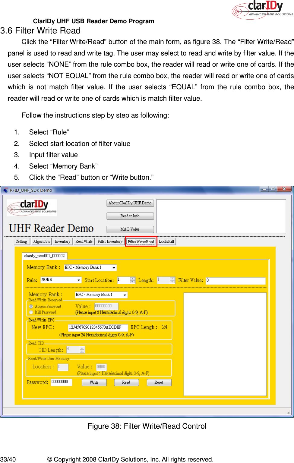
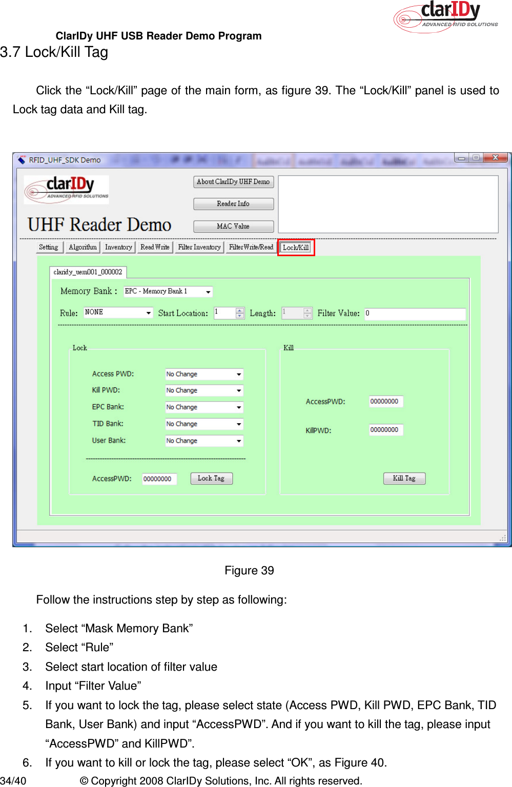
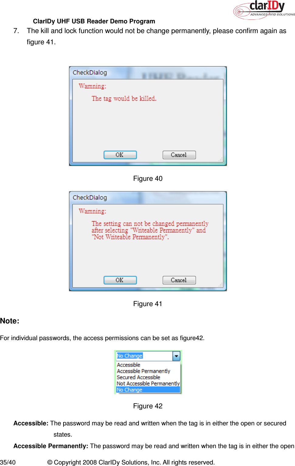
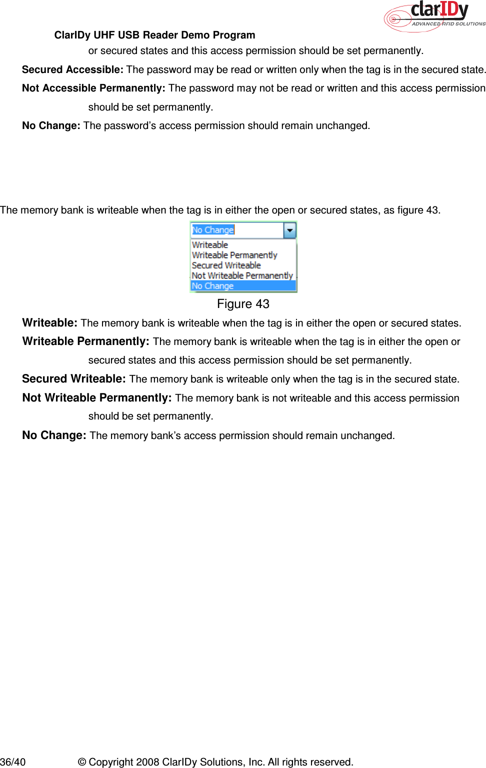
Users Manual 2
3.
Users Manual 3
4.
Users Manual 4
Users Manual 2
Navigation menu
Upload a User Manual
Namespaces
Wiki Guide
HTML
PDF
Info
Views
User Manual
Discussion / Help
Navigation