ClarIDy Solutions UEE007 UHF READER MODULE User Manual 2
ClarIDy Solutions, Inc. UHF READER MODULE Users Manual 2
Contents
- 1. Users Manual 1
- 2. Users Manual 2
- 3. Users Manual 3
- 4. Users Manual 4
Users Manual 2

ClarIDy UHF USB Reader Demo Program
1/40 © Copyright 2008 ClarIDy Solutions, Inc. All rights reserved.
ClarIDy UHF USB Reader Demo Program
User’s Manual for Win32
Version: A.2-02
2009-01-05
ClarIDy Solutions, Inc.
Model No.: UEE005

ClarIDy UHF USB Reader Demo Program
2/40 © Copyright 2008 ClarIDy Solutions, Inc. All rights reserved.
Copyright Notice
© Copyright 2008 ClarIDy Solutions, Inc. All rights reserved.
No part of this document may be reproduced without the prior written permission of ClarIDy Solutions, Inc.
Disclaimer
The information of this document is subject to change without notice and does not represent a commitment on any part
of ClarIDy Solutions, Inc.
Trademarks
Intel is a registered trademark of Intel Corporation.
AMD is a registered trademark of Advanced Micro Devices, Inc.
Microsoft, Windows Vista, Windows XP, Visual Studio, .NET Framework, and CSharp (C#) are registered trademarks
of Microsoft Corporation.
All other product names are trademarks or registered trademarks of their respective owners.

ClarIDy UHF USB Reader Demo Program
3/40 © Copyright 2008 ClarIDy Solutions, Inc. All rights reserved.
Change Log
Revision Date Author Description
A.1 2008.09.02. Hoe Huang Create the ClarIDy UHF Demo Program User’s Manual.
A.2 2008.11.07 Hoe Huang Modified Demo Program User’s Manual, and added
examples.
A.2-01 2008.12.09 Jun-Rong Chang Added the application of Lock Tag and Kill Tag
A.2-02 2009.01.05 Jun-Rong Chang Added the application of enable password function and
write password.

ClarIDy UHF USB Reader Demo Program
4/40 © Copyright 2008 ClarIDy Solutions, Inc. All rights reserved.
Table of Contents
1. Introduction..................................................................................................................5
2. Installation ...................................................................................................................6
2.1 Prerequisites to Installation............................................................................................................ 6
2.2 Setup the USB Driver .................................................................................................................... 6
2.3 Install .Net Framework 2.0........................................................................................................... 12
2.3 Install ClarIDy UHF Demo ........................................................................................................... 15
3. Demo Program Operation Guide ...............................................................................19
3.1 Setting Control ............................................................................................................................. 19
3.2 Algorithm Control ......................................................................................................................... 22
3.3 Inventory Control ......................................................................................................................... 27
3.4 Read/Write Control ...................................................................................................................... 29
3.5 Filter Inventory ............................................................................................................................. 31
3.6 Filter Write Read .......................................................................................................................... 33
3.7 Lock/Kill Tag................................................................................................................................. 34
4. Error Code.................................................................................................................37
5. Uninstall.....................................................................................................................39

ClarIDy UHF USB Reader Demo Program
5/40 © Copyright 2008 ClarIDy Solutions, Inc. All rights reserved.
1. Introduction
This document describes the demo program (ClarIDy_UHF_Demo_Setup.exe) for
ClarIDy UHF RFID Reader. The demo program provides “Setting”, “Algorithm”, “Inventory”,
“Read/Write”, “Filter Inventory”, “Filter Read/Write” and “Lock/Kill” functions. Users can use
this application to control the ClarIDy UHF RFID Reader to communicate with EPC RFID tags.
The operational procedures are described as the following chapters.

ClarIDy UHF USB Reader Demo Program
6/40 © Copyright 2008 ClarIDy Solutions, Inc. All rights reserved.
2. Installation
Before Installing the USB Driver and ClarIDy UHF Demo program, please see
prerequisites first.
2.1 Prerequisites to Installation
In order to run ClarIDy UHF Demo program as smoothly as possible, we recommend
some conditions as following.
2.1.1 Hardware Platform Requirements
The following hardware Platforms are supported by ClarIDy UHF RFID Reader.
CPU: Intel
®
Pentium
®
4 or AMD Athlon™ processor, 1.4 GHz or above
RAM: 512MB or above
2.1.2 Operating System Requirements
The following host operating systems are supported by ClarIDy UHF RFID Reader:
Microsoft
®,
Windows Vista
®
, Windows XP
®
with Service Pack 2 or Service Pack 3 on
an IA-32 platform; USB Host Controller – OHCI, UHCI or EHCI
2.1.3 Other Software Requirements
The following other systems are supported by ClarIDy UHF RFID Reader:
Microsoft
®
.Net Framework
®
Release 2.0
Microsoft
®
Visual C++ Libraries 2008
2.2 Setup the USB Driver
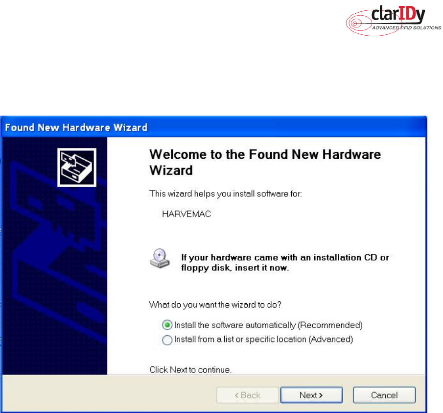
First time using the ClarIDy’s UHF RFID Reader (USB Interface), you must install the
driver. (The Driver programs are located in the “drivers” folder of the disc.)
Please directly connect the ClarIDy UHF RFID Reader to the USB port of the computer.
The Windows system will detect the ClarIDy UHF RFID Reader as a new device and popup
the device driver setup dialog, as figure 1.
Install ClarIDy UHF RFID driver step by step as the following instructions:
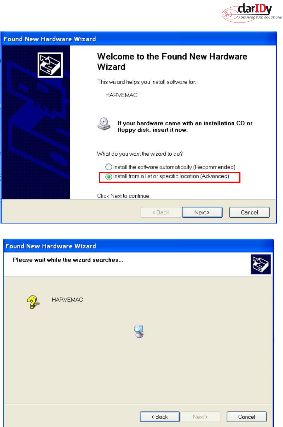
1. Select “Install from a list or specific location (Advanced)”, as figure 2.
2. Click “Next” while the wizard searches, as figure 3.
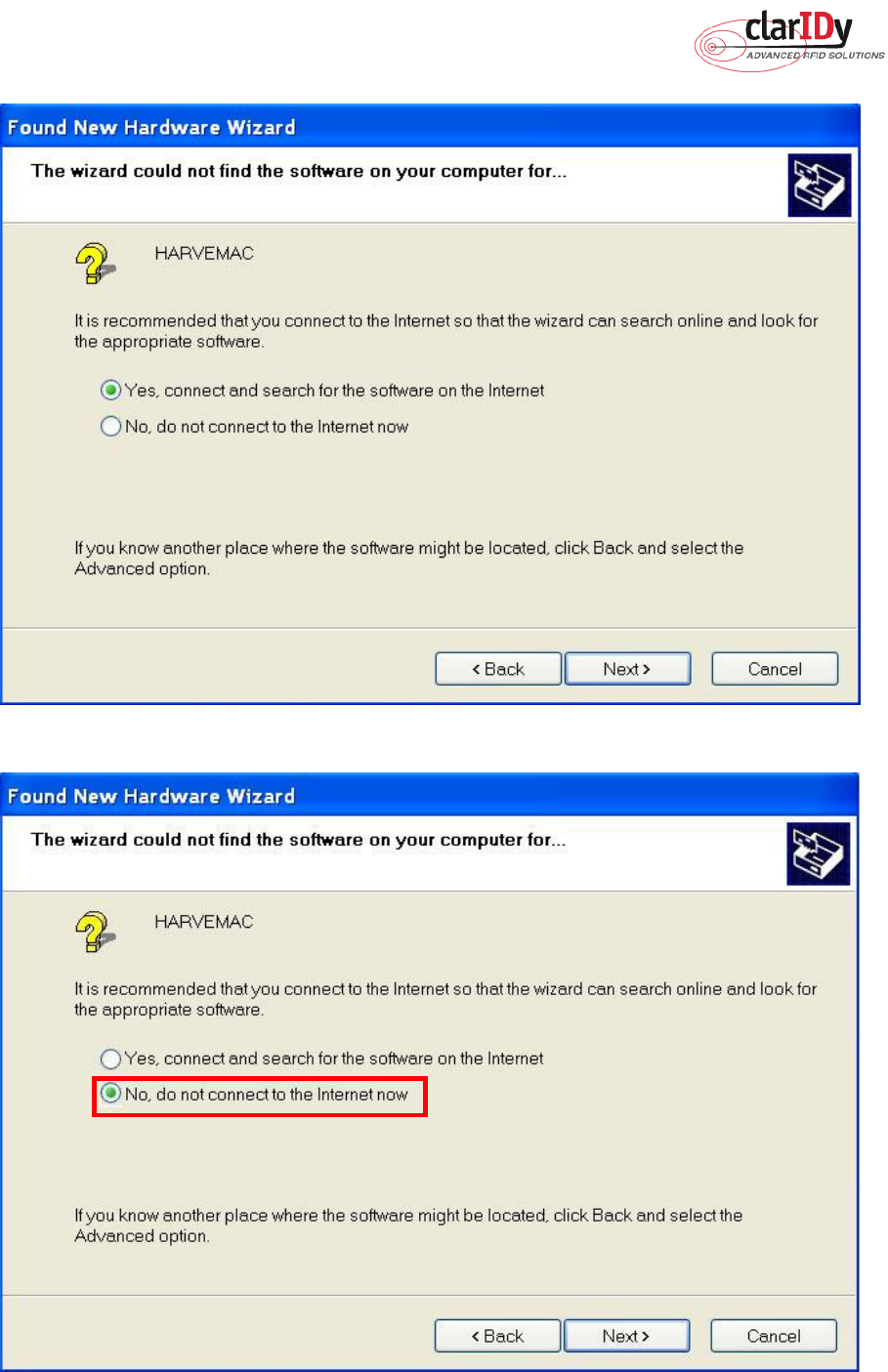
3. System show out figure 4.
4. Select “No, do not connect to the internet now”, as figure 5.
ClarIDy UHF USB Reader Demo Program
7/40 © Copyright 2008 ClarIDy Solutions, Inc. All rights reserved.
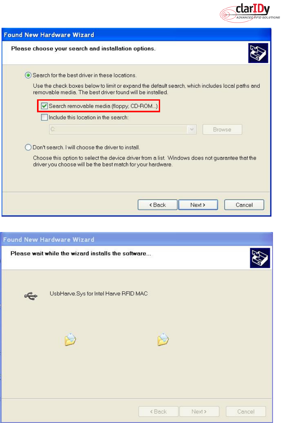
5. Click “Next” while the installation option dialog is shown, as figure 6.
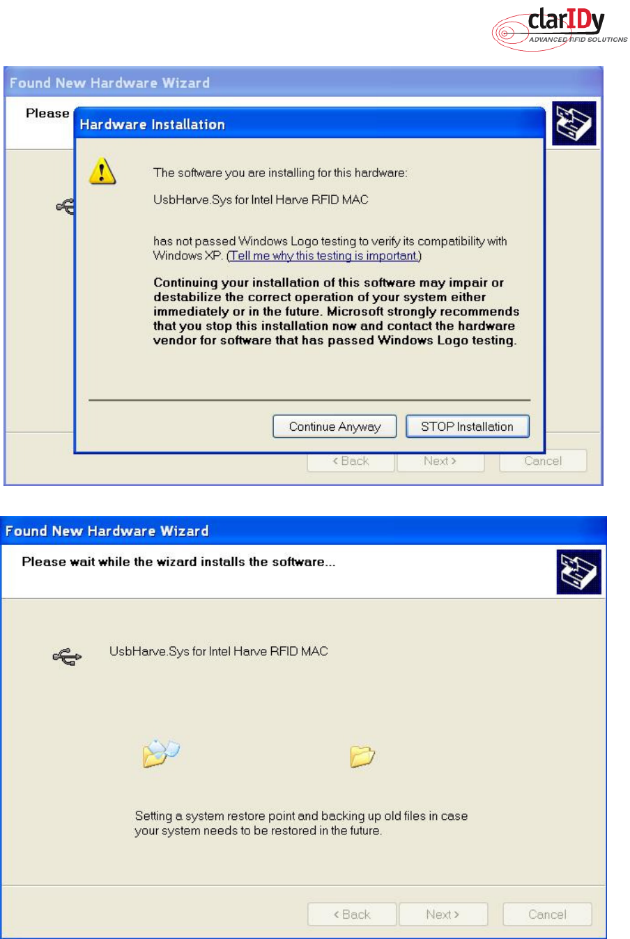
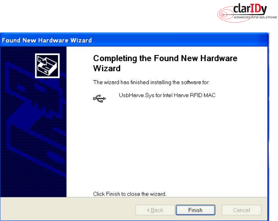
6. When “Hardware Installation” dialog is shown, please click “Continue Anyway” to
continue the installation, as figure 8 and figure 9.
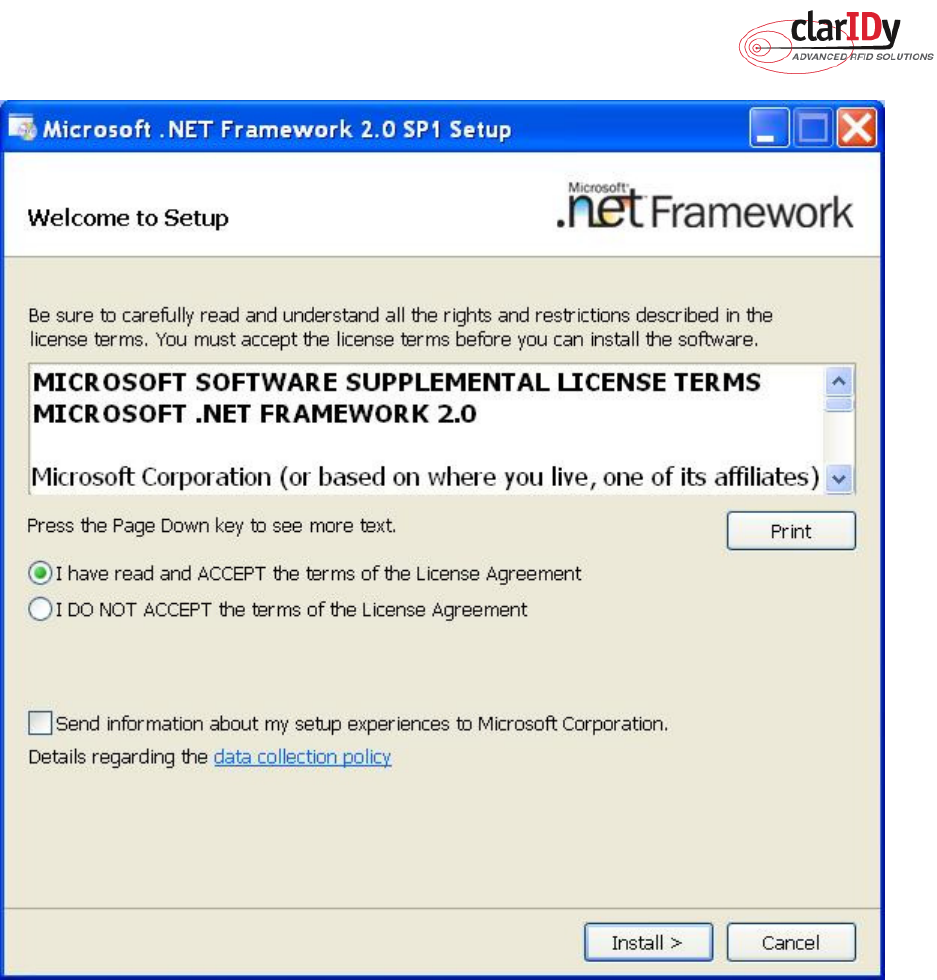
7. Click “Finish” to finalize the installation of the RFID USB device driver, as figure 10.
Figure 1
ClarIDy UHF USB Reader Demo Program
8/40 © Copyright 2008 ClarIDy Solutions, Inc. All rights reserved.
Figure 2
Figure 3
ClarIDy UHF USB Reader Demo Program
9/40 © Copyright 2008 ClarIDy Solutions, Inc. All rights reserved.
Figure 4
Figure 5
ClarIDy UHF USB Reader Demo Program
10/40 © Copyright 2008 ClarIDy Solutions, Inc. All rights reserved.
Figure 6
Figure 7
ClarIDy UHF USB Reader Demo Program
11/40 © Copyright 2008 ClarIDy Solutions, Inc. All rights reserved.
Figure 8
Figure 9
ClarIDy UHF USB Reader Demo Program
12/40 © Copyright 2008 ClarIDy Solutions, Inc. All rights reserved.
Figure 10
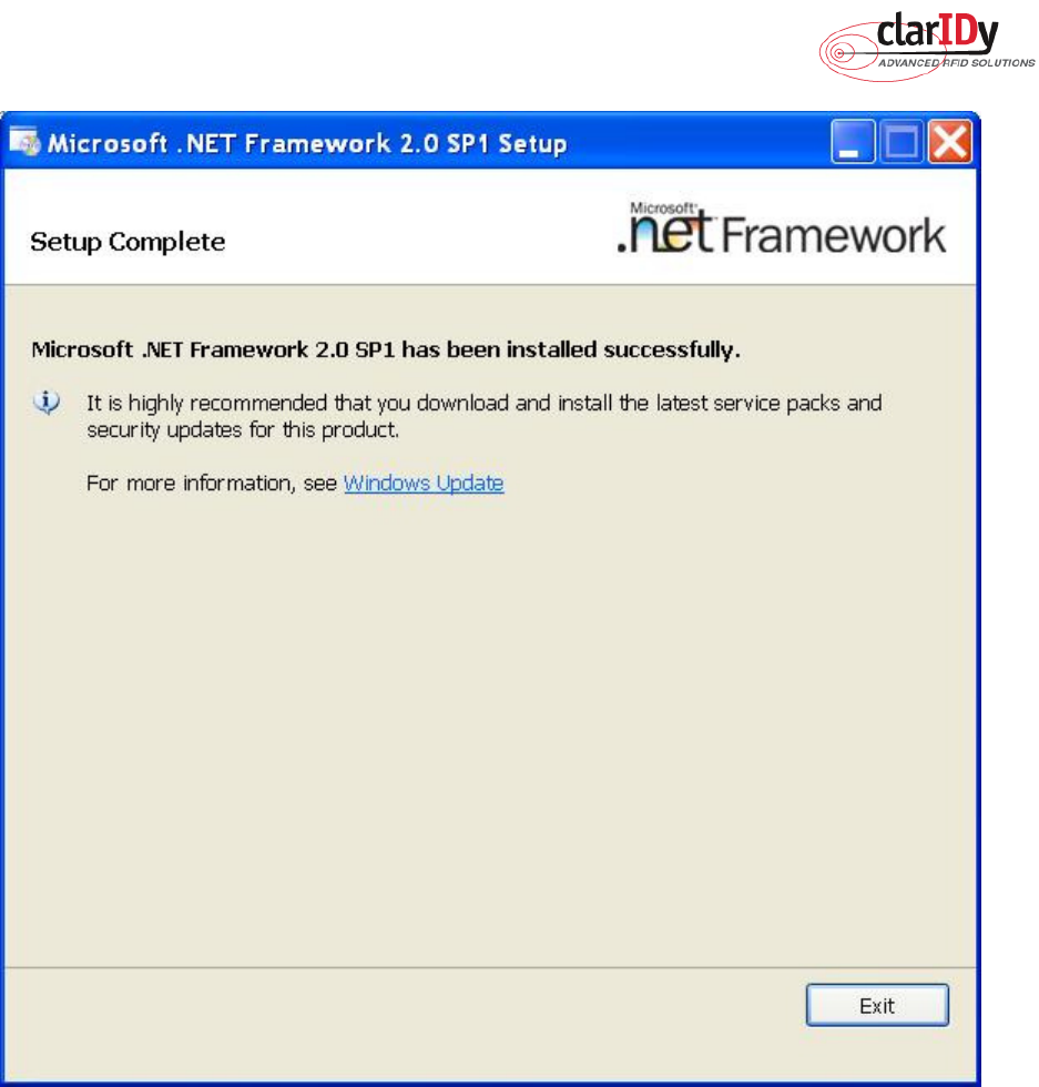
2.3 Install .Net Framework 2.0
If your O/S doesn’t have installed .Net Framework 2.0 yet, “Setup.exe” would install .Net
Framework 2.0 automatically. And install .Net Framework 2.0 step by step as the following
instructions:
1. Double click “Setup.exe” (The file is located in the win32 folder of the disc.)
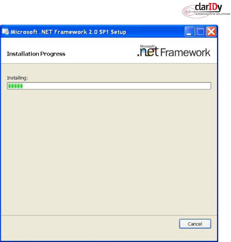
2. Select Read and accept the terms of the license agreement, and click “Install”, as figure
11.
3. Wait the installation, as figure 12.
4. Click “Exit” to finish the installation, as figure 13.
ClarIDy UHF USB Reader Demo Program
13/40 © Copyright 2008 ClarIDy Solutions, Inc. All rights reserved.
Figure 11
ClarIDy UHF USB Reader Demo Program
14/40 © Copyright 2008 ClarIDy Solutions, Inc. All rights reserved.
Figure 12
ClarIDy UHF USB Reader Demo Program
15/40 © Copyright 2008 ClarIDy Solutions, Inc. All rights reserved.
Figure 13
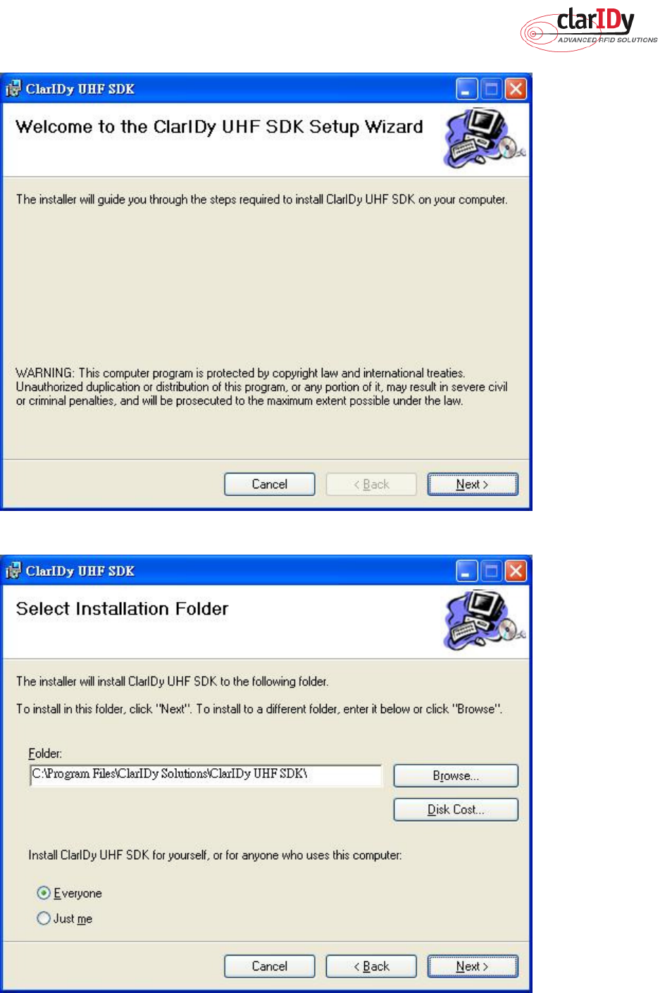
2.3 Install ClarIDy UHF Demo
Install ClarIDy UHF Demo step by step as the following instructions:
1. Double click “Setup.exe” which is in the disc (The file is located in the win32 folder of
the disc.).
2. Click “Next”, as figure 14.
3. Click “Browser” to the Folder to install and select the user, and click “Next”, as figure 15.
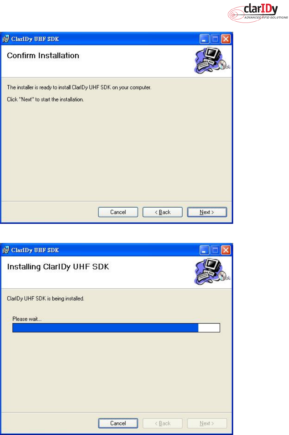
4. Click “Next” to start installation, as figure 16.
5. Wait for the installation, as figure 17.
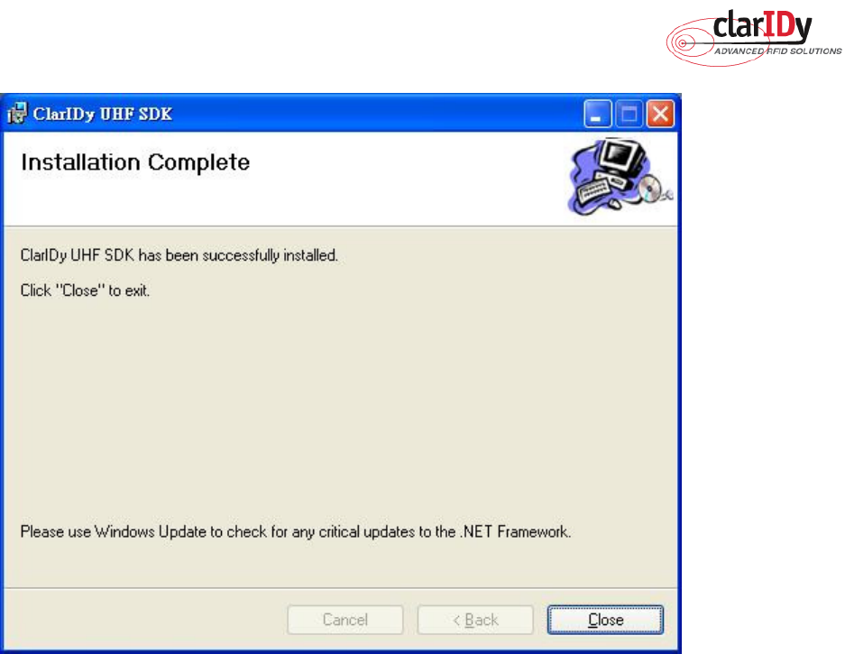
6. Click “Close” to exit, as figure 18.
ClarIDy UHF USB Reader Demo Program
16/40 © Copyright 2008 ClarIDy Solutions, Inc. All rights reserved.
Figure 14
Figure 15
ClarIDy UHF USB Reader Demo Program
17/40 © Copyright 2008 ClarIDy Solutions, Inc. All rights reserved.
Figure 16
Figure 17
ClarIDy UHF USB Reader Demo Program
18/40 © Copyright 2008 ClarIDy Solutions, Inc. All rights reserved.
Figure 18
ClarIDy UHF USB Reader Demo Program
19/40 © Copyright 2008 ClarIDy Solutions, Inc. All rights reserved.
3. Demo Program Operation Guide
The following sections will describe the usage of the ClarIDy UHF Demo application. The
application is include seven Controls, “Setting Control”, “Algorithm Control”, ”Set-Session
Control”, “Inventory Control”, “Read/Write Control”, “Filter Inventory Control”, “Filter
Read/Write Control” and “Lock/Kill Control”.
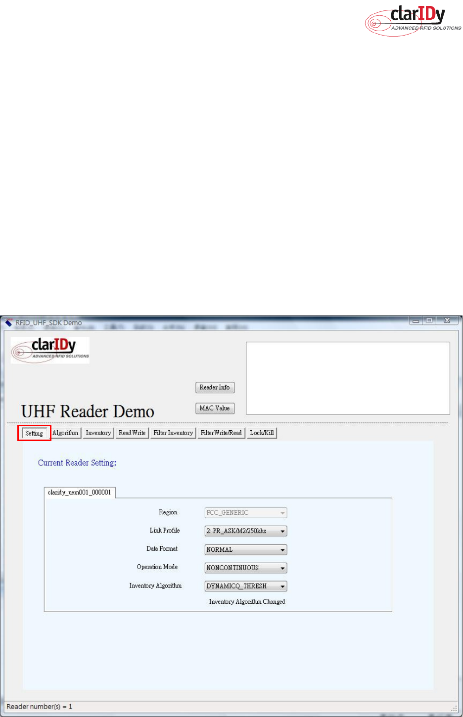
3.1 Setting Control
Click the “Setting” button of the main form, as figure 19. The Settings Page is displayed.
This page allows the user to configure the following items:
Link Profile
Data Format ( Compact, Normal or Extended )
Operational Mode ( Continuous Mode or Discontinuous Mode )
Inventory Algorithm ( Fixed “Q”, Variable “Q”, Variable “Q” Adjustable or Variable “Q”
Threshold )
ClarIDy UHF USB Reader Demo Program
20/40 © Copyright 2008 ClarIDy Solutions, Inc. All rights reserved.
Figure 19: Setting View Panel
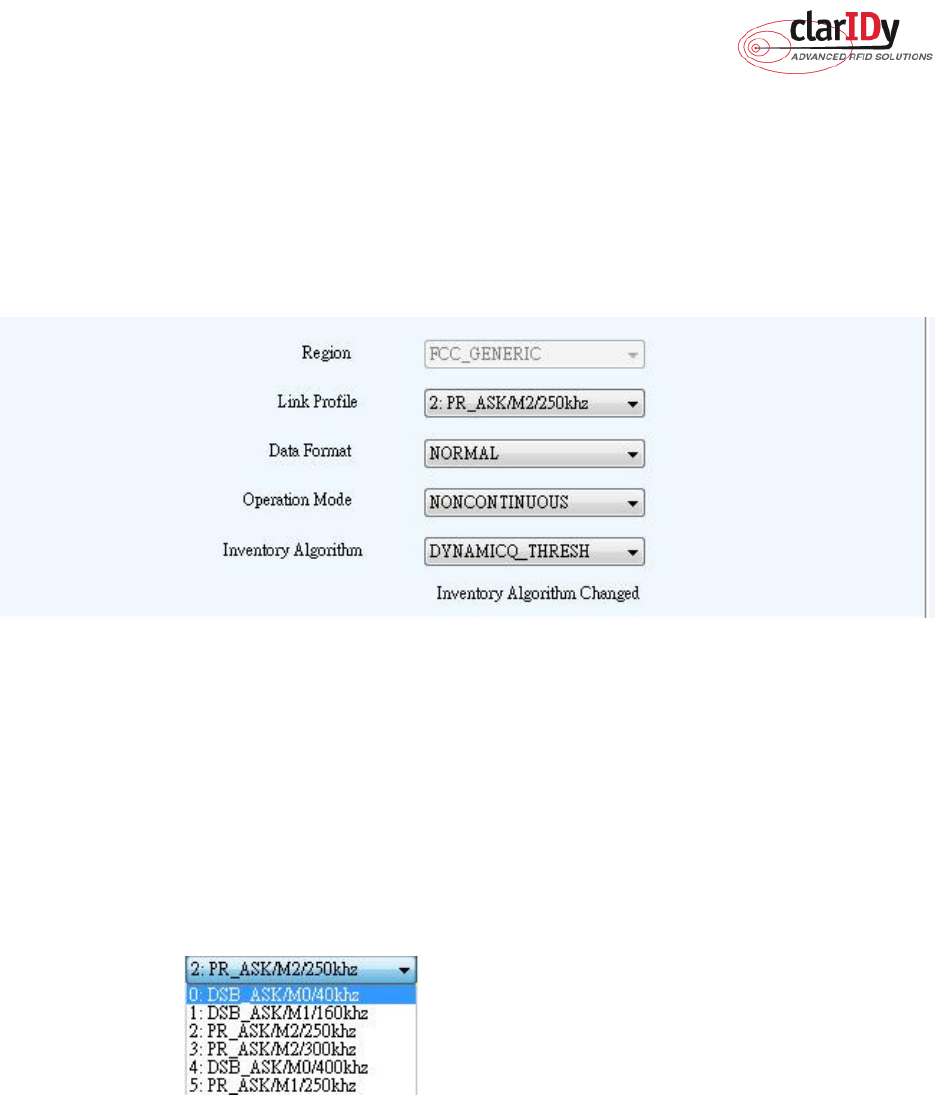
As you can see in Figure 20, the settings page has a two column layout. The left column
is used to specify the startup settings that will be automatically applied to the reader when the
application starts. The right column allows the user to change the current reader configuration.
Figure 20: Settings
1. Link Profile: Sets the current link profile for the reader module, as figure 21. The option
is as follows:
0: DSB ASK / MO / 40 khz
1: DSB_ASK / M1 / 160 khz
2: PR_ASK / M2 / 25U khz
3: PR_ASK / M2 / 300 khz
4: DSB_ASK / MO / 400 khz
5: PR_ASK / M1 / 250 khz
Figure 21
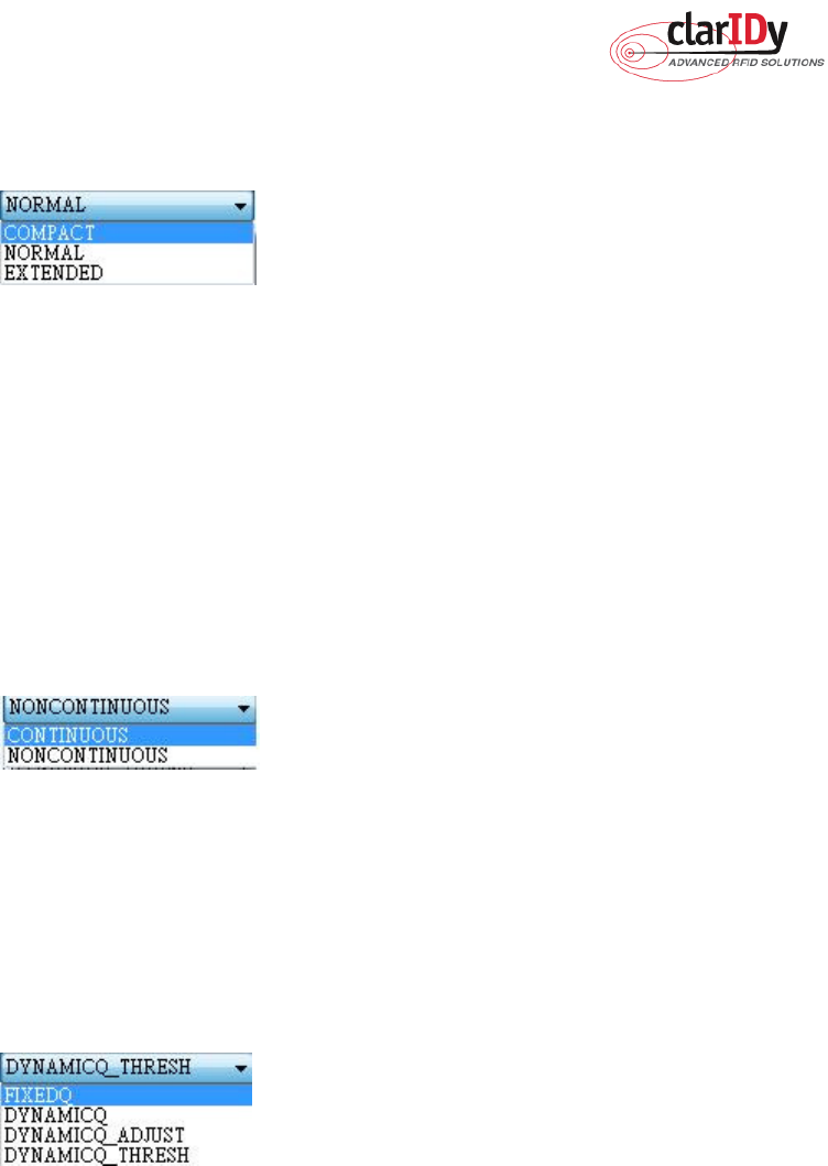
2. Data Format: Sets the operation response data reporting mode for tag-protocol
operations, as figure 22. The option is as follows:
COMPACT: The response data is limited to provide the application with the pertinent
tag-access operation data, but minimize the amount of MAC-to-host
communication overhead.
NORMAL: The response data builds on the compact mode to provide the
application with status and contextual information to give additional
finer-grained feedback such as the beginning of inventory cycles, etc.
EXTENDED: The response data builds on the normal mode by providing additional
ClarIDy UHF USB Reader Demo Program
21/40 © Copyright 2008 ClarIDy Solutions, Inc. All rights reserved.
diagnostics and statistical information.
Figure 22
3. Operation Mode: Sets the reader's operation mode, as figure 23. The option is as
follows:
CONTINUOUS: In continuous mode, when a tag-protocol-operation cycle (i.e., one
iteration through all enabled antenna ports) has completed, the reader module
will begin a new tag-protocol-operation cycle with the first enabled antenna port
and will continue to do so until the operation is explicitly cancelled by the
application.
NONCONTINUOUS: In non-continuous mode, only a single tag-protocol-operation
cycle is executed upon the reader module.
Figure 23
4. Inventory Algorithm: Allows the application to set the currently-active singulation
algorithm, as figure 24. The option is as follows:
0: ALGORITHM_FIXEDQ
1: DYNAMICQ
2: DYNAMICQ_ADJUST
3: DYNAMICQ_THRESHOLD
Figure 24
ClarIDy UHF USB Reader Demo Program
22/40 © Copyright 2008 ClarIDy Solutions, Inc. All rights reserved.
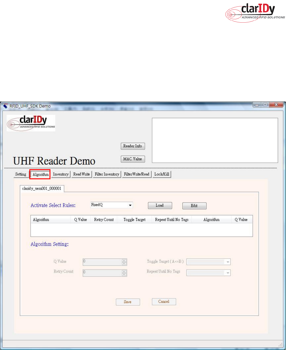
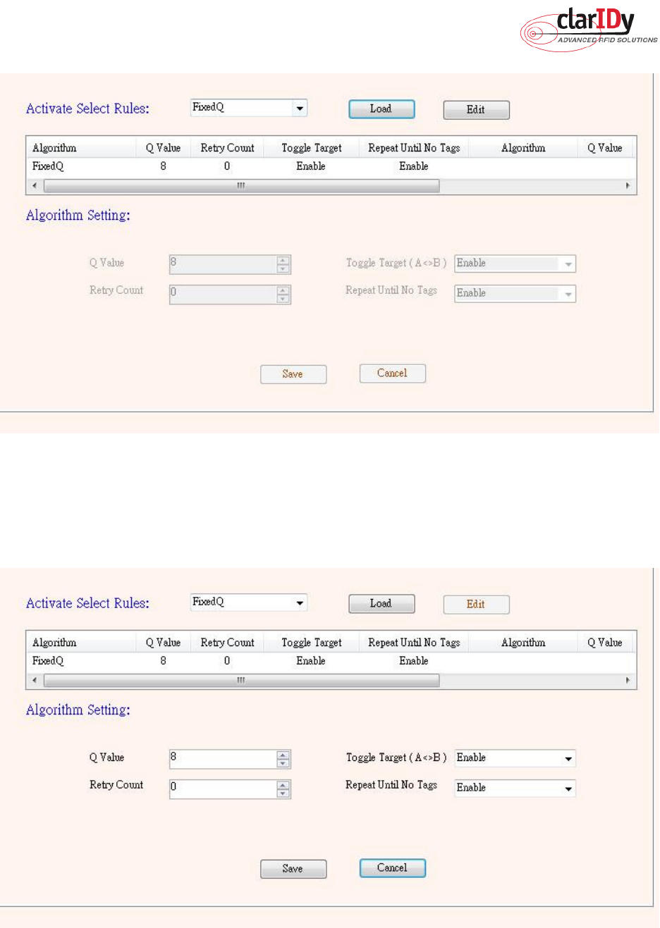
3.2 Algorithm Control
Click the “Algorithm” button of the main form, as figure 25. The Algorithm pane is used to
view, the parameters for the selected singulation algorithm. The user may select Fixed Q,
Dyanmic Q, Dynamic Q Adjustable and Dynamic Q Threshold from the Active Algorithm
combo box and click “Load” button to query the current selected Algorithm and refresh the
values displayed in the Algorithm Settings View panel, as figure 26.
Figure 25: Algorithm View Panel
ClarIDy UHF USB Reader Demo Program
23/40 © Copyright 2008 ClarIDy Solutions, Inc. All rights reserved.
Figure 26: Load Value
To modify the algorithm settings for the current reader, click on the “Edit” button. This will
enable a algorithm setting panel similar to the one shown in Figure 27.
Figure 27: Modify Algorithm Settings

ClarIDy UHF USB Reader Demo Program
24/40 © Copyright 2008 ClarIDy Solutions, Inc. All rights reserved.
1. FixedQ : Fixed Q algorithm. The items as follows:
1: qValue:
The Q value to use. Valid values are 0 to 15, inclusive.
2: retryCount:
Specifies the number of times to try another execution of the
singulation algorithm for the specified session/target before either toggling
the target (if toggleTarget is non-zero) or terminating the inventory/tag access
operation. Valid values are 0-255, inclusive.
3: toggleTarget:
A flag that indicates if, after performing the inventory cycle for the
specified target (i.e., A or B), if the target should be toggled (i.e., A to B or B to
A) and another inventory cycle run. A non-zero value indicates that the target
should be toggled. A zero value indicates that the target should not be
toggled. Note that if the target is toggled, retryCount and repeatUntilNoTags
will also apply to the new target.
4: repeatUntilNoTags:
A flag that indicates whether or not the singulation algorithm
should continue performing inventory rounds until no tags are singulated. A
non-zero value indicates that, for each execution of the singulation algorithm,
inventory rounds should be performed until no tags are singulated. A zero
value indicates that a single inventory round should be performed for each
execution of the singulation algorithm.
2. DynamicQ: Adjusts the Q value based on the presence or absence of tags. The items
as follows:
1: startQValue:
The starting Q value to use. Valid values are 0 to 15, inclusive.
minQValue <= startQValue <= maxQValue
2: minQValue:
The minimum Q value to use. Valid values are 0 to 15, inclusive.
minQValue <= startQValue <= maxQValue
3: maxQValue:
The maximum Q value to use. Valid values are 0 to 15, inclusive.
minQValue <= startQValue <= maxQValue
4: retryCount:
Specifies the number of times to try another execution of the singulation
algorithm for the specified session/target before either toggling the target (if
toggleTarget is non-zero) or terminating the inventory/tag access operation.
Valid values are 0-255, inclusive.
5: maxQueryRepCount:
The maximum number of ISO 18000-6C QueryRep
commands that will follow the ISO 18000-6C Query command during a single
inventory round. Valid values are 0-255, inclusive.
6: toggleTarget:
A flag that indicates if, after performing the inventory cycle for the
specified target (i.e., A or B), if the target should be toggled (i.e., A to B or B to
A) and another inventory cycle run. A non-zero value indicates that the target
should be toggled. A zero value indicates that the target should not be
toggled. Note that if the target is toggled, retryCount and repeatUntilNoTags

ClarIDy UHF USB Reader Demo Program
25/40 © Copyright 2008 ClarIDy Solutions, Inc. All rights reserved.
will also apply to the new target.
3. DynamicQAdjust: This algorithm modifies the previous dynamic Q algorithm by issuing
ISO 18000-6C Query Adjust commands instead of ISO 18000-6C Query
commands when adjusting the Q value. The items as follows:
1: startQValue:
The starting Q value to use. Valid values are 0 to 15, inclusive.
minQValue <= startQValue <= maxQValue
2: minQValue:
The minimum Q value to use. Valid values are 0 to 15, inclusive.
minQValue <= startQValue <= maxQValue
3: maxQValue:
The maximum Q value to use. Valid values are 0 to 15, inclusive.
minQValue <= startQValue <= maxQValue
4: retryCount:
Specifies the number of times to try another execution of the singulation
algorithm for the specified session/target before either toggling the target (if
toggleTarget is non-zero) or terminating the inventory/tag access operation.
Valid values are 0-255, inclusive.
5: maxQueryRepCount:
The maximum number of ISO 18000-6C QueryRep
commands that will follow the ISO 18000-6C Query command during a single
inventory round. Valid values are 0-255, inclusive.
6: toggleTarget:
A flag that indicates if, after performing the inventory cycle for the
specified target (i.e., A or B), if the target should be toggled (i.e., A to B or B to
A) and another inventory cycle run. A non-zero value indicates that the target
should be toggled. A zero value indicates that the target should not be
toggled. Note that if the target is toggled, retryCount and repeatUntilNoTags
will also apply to the new target.
4. DynamicQThreshold: This algorithm uses a Q-modification algorithm that allows the
application to control the change of the Q-adjustment-threshold value. The items
as follows:
1: startQValue:
The starting Q value to use. Valid values are 0 to 15, inclusive.
minQValue <= startQValue <= maxQValue
2: minQValue:
The minimum Q value to use. Valid values are 0 to 15, inclusive.
minQValue <= startQValue <= maxQValue
3: maxQValue:
The maximum Q value to use. Valid values are 0 to 15, inclusive.
minQValue <= startQValue <= maxQValue
4:retryCount:
Specifies the number of times to try another execution of the singulation
algorithm for the specified session/target before either toggling the target (if
toggleTarget is non-zero) or terminating the inventory/tag access operation.
Valid values are 0-255, inclusive.
5: toggleTarget:
A flag that indicates if, after performing the inventory cycle for the
specified target (i.e., A or B), if the target should be toggled (i.e., A to B or B to

ClarIDy UHF USB Reader Demo Program
26/40 © Copyright 2008 ClarIDy Solutions, Inc. All rights reserved.
A) and another inventory cycle run. A non-zero value indicates that the target
should be toggled. A zero value indicates that the target should not be
toggled. Note that if the target is toggled, retryCount and repeatUntilNoTags
will also apply to the new target.
6: thresholdMultiplier:
The multiplier, specified in units of fourths (i.e., 0.25), that will
be applied to the Q-adjustment threshold as part of the dynamic-Q algorithm.
Valid values are 0-255, inclusive.
ClarIDy UHF USB Reader Demo Program
27/40 © Copyright 2008 ClarIDy Solutions, Inc. All rights reserved.
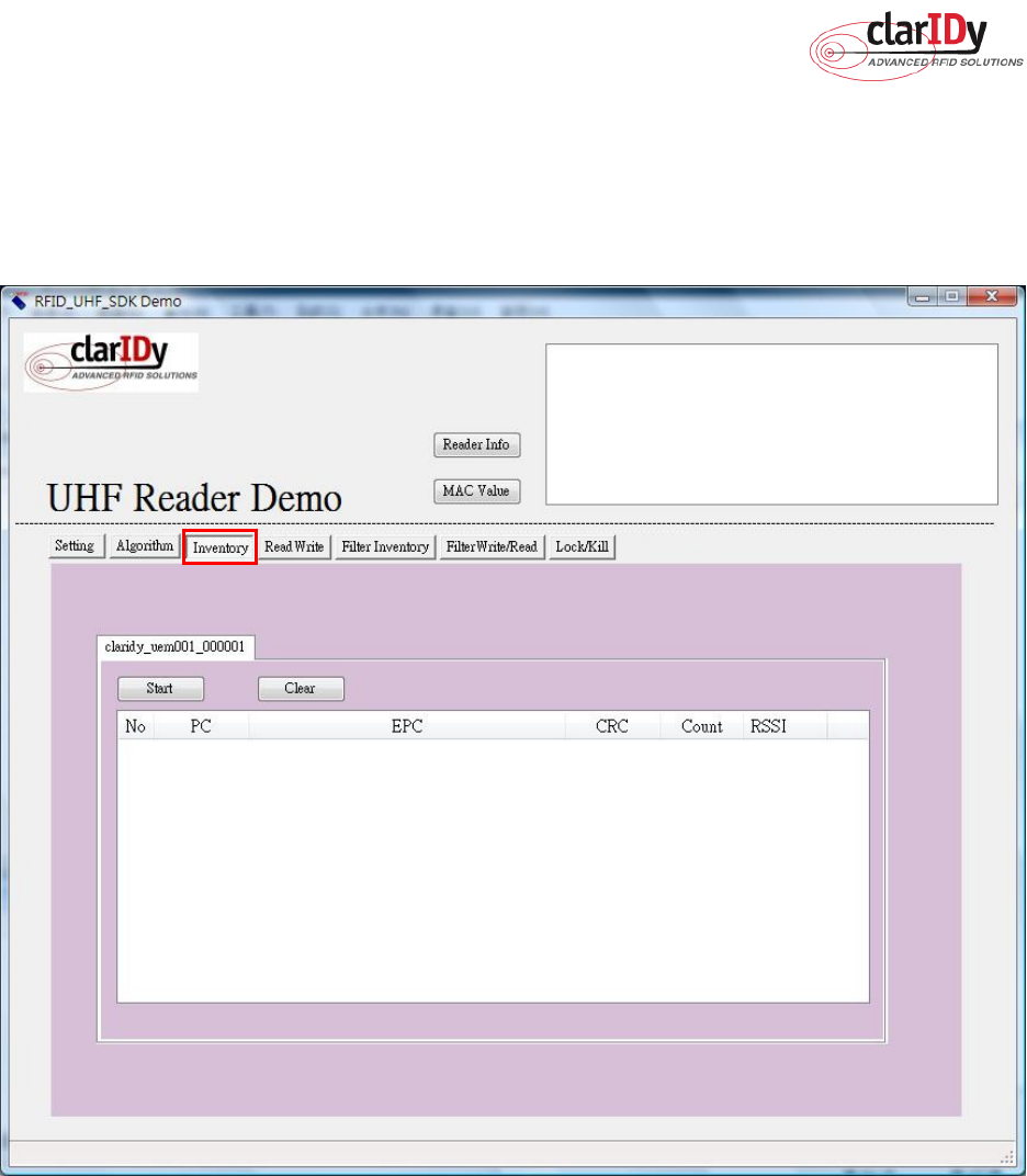
3.3 Inventory Control
Click the “Inventory” button of the main form, as figure 28. The Inventory panel is used to
read tag data and view tag data. Click the “Start” button to read tags, as figure 29.
Figure 28: Inventory Control.
ClarIDy UHF USB Reader Demo Program
28/40 © Copyright 2008 ClarIDy Solutions, Inc. All rights reserved.
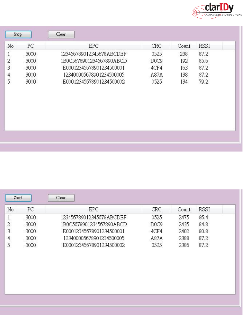
Figure 29: Start Read Tags
Click the “Stop” button to stop read tags, as figure 30.
Figure 30: Stop Read Tags
ClarIDy UHF USB Reader Demo Program
29/40 © Copyright 2008 ClarIDy Solutions, Inc. All rights reserved.
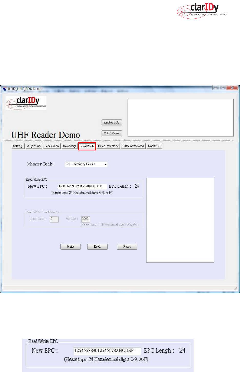
3.4 Read/Write Control
Click the “Read/Write” button of the main form, as figure 31. The “Read/Write” panel is
used to read tag data and write tag data. The user may select “Reserved – Memory Band 0”,
“EPC – Memory Band 1”, “TID – Memory Band 2” and “User – Memory Band 3” from the
Memory Bank combo box. When this combo box is modified, the group box enabled with the
indicated memory bank in the “Read/Write” panel.
Figure
31:
Read/Write Control
The user can write or read EPC code and User Memory. When the user wants to write
EPC, the user must input 24 hexadecimal digits, as figure 32.
ClarIDy UHF USB Reader Demo Program
30/40 © Copyright 2008 ClarIDy Solutions, Inc. All rights reserved.
Figure 32: Write EPC
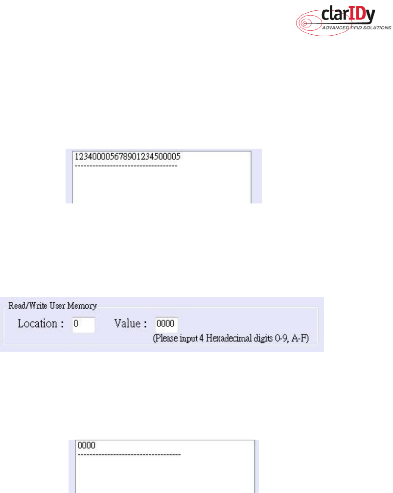
When the user wants to read EPC, the user clicks the “Read” button and value is showed
to message list, as figure 33.
Figure 33: Read EPC
When the user wants to write User Memory, the user must input location and 4
hexadecimal digits, as figure 34
.
Figure 34: Write User Memory
When the user wants to read User Memory, the user must input location and value is
showed to message list, as figure 35.
Figure 35: Read User Memory
ClarIDy UHF USB Reader Demo Program
31/40 © Copyright 2008 ClarIDy Solutions, Inc. All rights reserved.
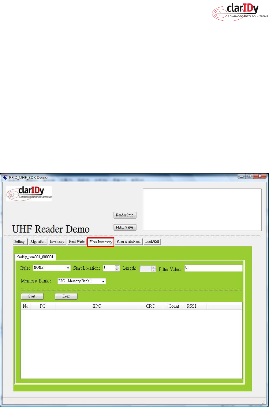
3.5 Filter Inventory
Click the “Filter Inventory” button of the main form, as figure 36. The “Filter Inventory”
panel is used to read tag UID. The user may select to read tag UID by filter value. If the user
selects “NONE” from the rule combo box, the reader will read all cards. If the user selects
“NOT EQUAL” from the rule combo box, the reader will read card which is not match filter
value. If the user selects “EQUAL” from the rule combo box, the reader will read card which is
match filter value.
Follow the instructions step by step as following:
1. Select “Rule”
2. Select start location of filter value
3. Input filter value
4. Select “Memory Bank”
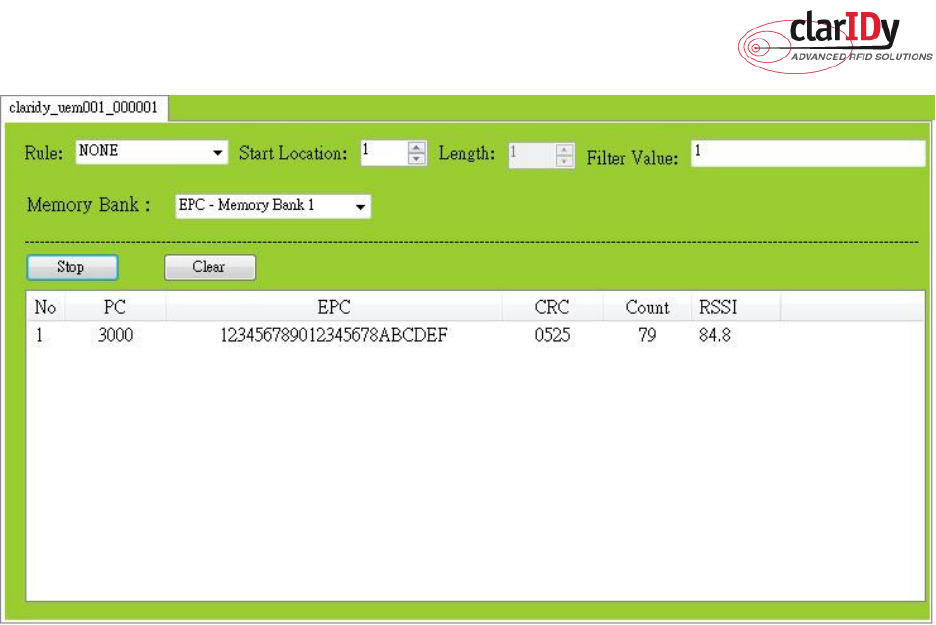
5. Click the “Start” button, the result as figure 37.
Figure 36: Filter Inventory Control
ClarIDy UHF USB Reader Demo Program
32/40 © Copyright 2008 ClarIDy Solutions, Inc. All rights reserved.
Figure 37
ClarIDy UHF USB Reader Demo Program
33/40 © Copyright 2008 ClarIDy Solutions, Inc. All rights reserved.
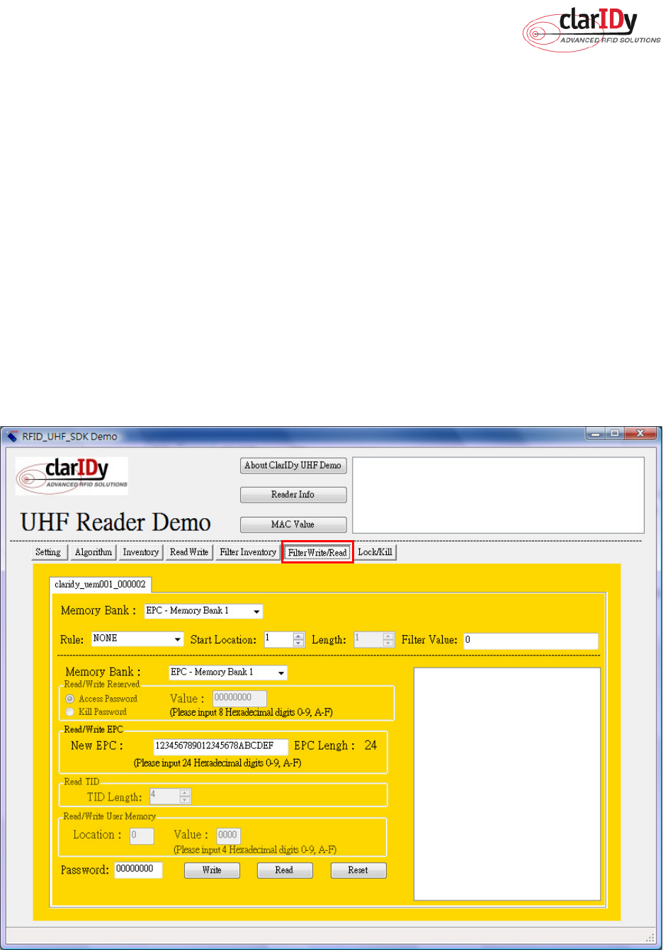
3.6 Filter Write Read
Click the “Filter Write/Read” button of the main form, as figure 38. The “Filter Write/Read”
panel is used to read and write tag. The user may select to read and write by filter value. If the
user selects “NONE” from the rule combo box, the reader will read or write one of cards. If the
user selects “NOT EQUAL” from the rule combo box, the reader will read or write one of cards
which is not match filter value. If the user selects “EQUAL” from the rule combo box, the
reader will read or write one of cards which is match filter value.
Follow the instructions step by step as following:
1. Select “Rule”
2. Select start location of filter value
3. Input filter value
4. Select “Memory Bank”
5. Click the “Read” button or “Write button.”
Figure 38: Filter Write/Read Control
ClarIDy UHF USB Reader Demo Program
34/40 © Copyright 2008 ClarIDy Solutions, Inc. All rights reserved.
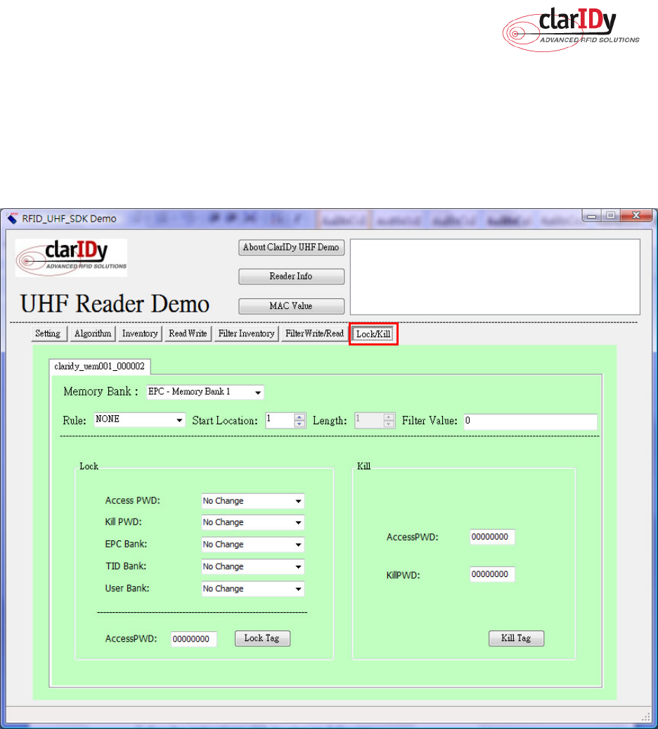
3.7 Lock/Kill Tag
Click the “Lock/Kill” page of the main form, as figure 39. The “Lock/Kill” panel is used to
Lock tag data and Kill tag.
Figure 39
Follow the instructions step by step as following:
1. Select “Mask Memory Bank”
2. Select “Rule”
3. Select start location of filter value
4. Input “Filter Value”
5. If you want to lock the tag, please select state (Access PWD, Kill PWD, EPC Bank, TID
Bank, User Bank) and input “AccessPWD”. And if you want to kill the tag, please input
“AccessPWD” and KillPWD”.
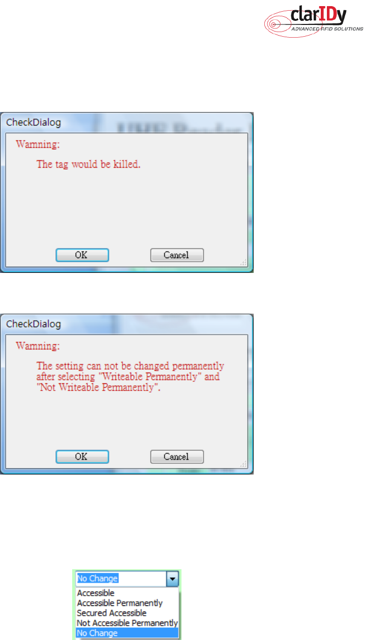
6. If you want to kill or lock the tag, please select “OK”, as Figure 40.
ClarIDy UHF USB Reader Demo Program
35/40 © Copyright 2008 ClarIDy Solutions, Inc. All rights reserved.
7. The kill and lock function would not be change permanently, please confirm again as
figure 41.
Figure 40
Figure 41
Note:
For individual passwords, the access permissions can be set as figure42.
Figure 42
Accessible: The password may be read and written when the tag is in either the open or secured
states.
Accessible Permanently: The password may be read and written when the tag is in either the open
ClarIDy UHF USB Reader Demo Program
36/40 © Copyright 2008 ClarIDy Solutions, Inc. All rights reserved.
or secured states and this access permission should be set permanently.
Secured Accessible: The password may be read or written only when the tag is in the secured state.
Not Accessible Permanently: The password may not be read or written and this access permission
should be set permanently.
No Change: The password’s access permission should remain unchanged.
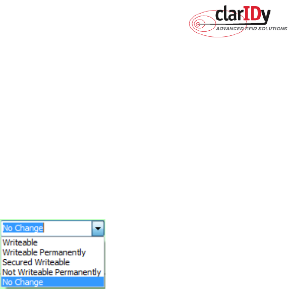
The memory bank is writeable when the tag is in either the open or secured states, as figure 43.
Figure 43
Writeable:
The memory bank is writeable when the tag is in either the open or secured states.
Writeable Permanently:
The memory bank is writeable when the tag is in either the open or
secured states and this access permission should be set permanently.
Secured Writeable:
The memory bank is writeable only when the tag is in the secured state.
Not Writeable Permanently:
The memory bank is not writeable and this access permission
should be set permanently.
No Change:
The memory bank’s access permission should remain unchanged.

ClarIDy UHF USB Reader Demo Program
37/40 © Copyright 2008 ClarIDy Solutions, Inc. All rights reserved.
4. Error Code
The following lists provide error codes of UHF Reader Demo Program. These values
are defined in the description.
Code (dec)
Description
0 Success
-9999 Attempted to open a reader that is already open
-9998 Buffer supplied is too small
-9997 General failure
-9996 Failed to load reader bus driver
-9995 Library cannot use version of reader bus driver present on system
-9994 Operation cannot be performed while library is in emulation mode
-9993 Antenna number is invalid
-9992 Reader handle provided is invalid
-9991 One of the parameters to the function is invalid
-9990 Attempted to open a non-existent reader
-9989 Library has not been successfully initialized
-9988 Function not supported
-9987 Operation was cancelled by call to cancel operation, close reader, or shut
down the library
-9986 Library encountered an error allocating memory
-9985 The operation cannot be performed because the reader is currently busy
-9984 The underlying reader module encountered an error
-9983 The reader has been detached from the system
-9982 The RFID library function is not allowed at this time.
-9981 The reader module's MAC firmware is not responding to requests.
-9980 The MAC firmware encountered an error while initiating the nonvolatile
memory update. The MAC firmware will return to its normal idle state
without resetting the reader module.
-9979 An attempt was made to write data to an address that is not in the valid
range of reader module nonvolatile memory addresses.
-9978 The MAC firmware encountered an error while trying to write to the reader
module's nonvolatile memory region.
-9977 The underlying transport layer detected that there was an overflow error
resulting in one or more bytes of the incoming data being dropped. The
operation was aborted and all data in the pipeline was flushed.

ClarIDy UHF USB Reader Demo Program
38/40 © Copyright 2008 ClarIDy Solutions, Inc. All rights reserved.
-7999 Fail to find reader
-7998 Fail to allocate memory
-7997 Write Data failure
-7996 Read Data failure
-7995 Lock Tag failure
-7994 Kill Tag failure
ClarIDy UHF USB Reader Demo Program
39/40 © Copyright 2008 ClarIDy Solutions, Inc. All rights reserved.
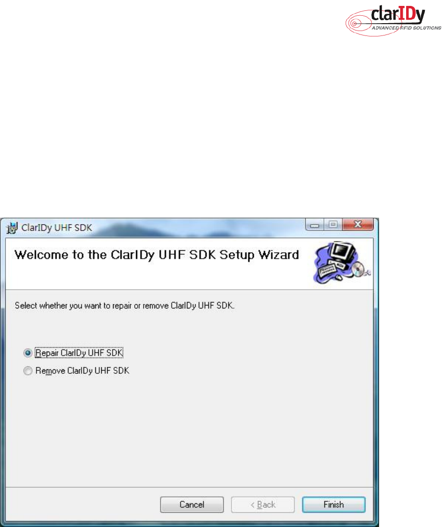
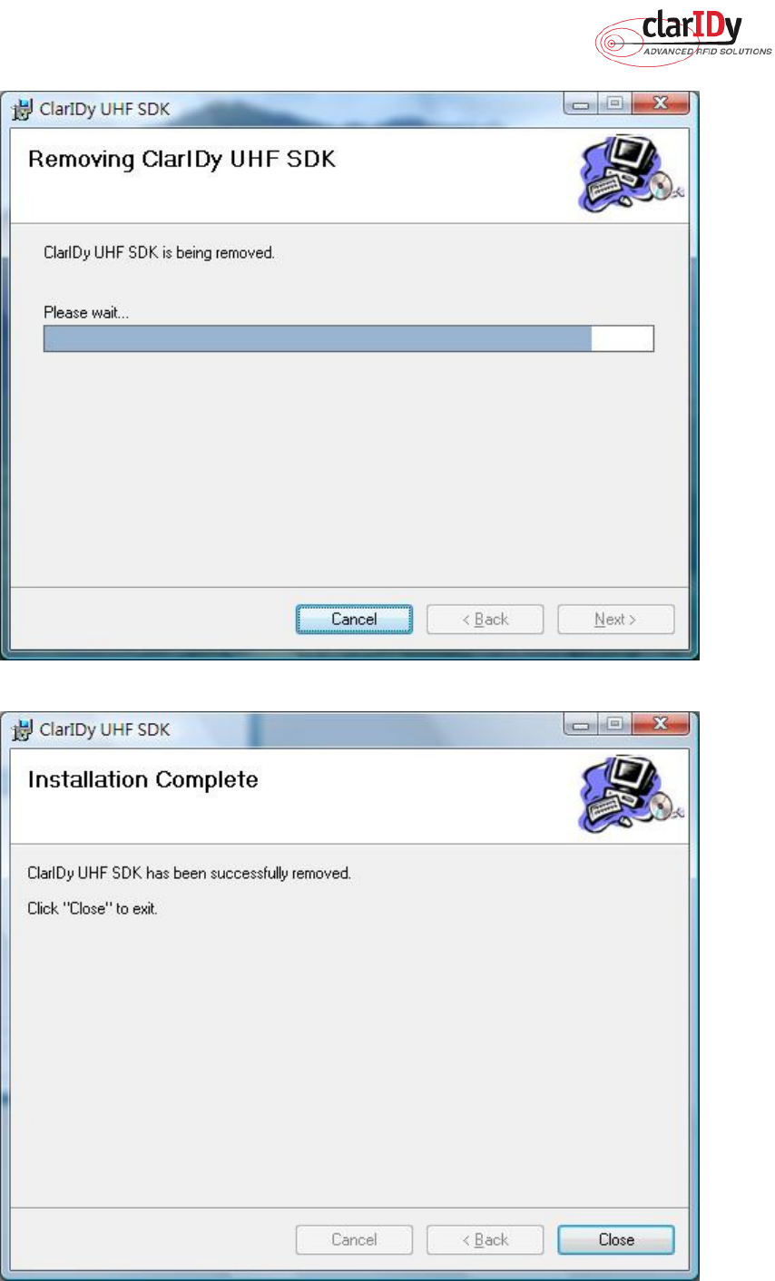
5. Uninstall
Uninstall ClarIDy UHF Demo program step by step as the following instructions:
1. Double click “Setup.exe” which is in the disc.
2. Select “Remove ClarIDy UHF Demo”, as figure 44.
3. Waiting system to remove, as figure 45.
4. The “ClarIDy UHF Demo” is completed removed and click “Close” to close window, as
figure 46.
Figure 44
ClarIDy UHF USB Reader Demo Program
40/40 © Copyright 2008 ClarIDy Solutions, Inc. All rights reserved.
Figure 45
Figure 46
Federal Communication Commission Interference Statement
This equipment has been tested and found to comply with the limits for a Class B digital device, pursuant
to Part 15 of the FCC Rules. These limits are designed to provide reasonable protection against harmful
interference in a residential installation. This equipment generates, uses
and can radiate radio frequency energy and, if not installed and used in accordance with the instructions,
may cause harmful interference
to radio communications. However, there is no guarantee that interference
will not occur in a particular installation. If this equipment does cause harmful interference to radio or
television reception, which can be determined by turning the equipment off and on, the user is
encouraged
to try to correct the interference by one of the following measures:
• Reorient or relocate the receiving antenna.
• Increase the separation between the equipment and receiver.
• Connect the equipment into an outlet on a circuit different from that to which the receiver is connected.
• Consult the dealer or an experienced radio/TV technician for help.
This device complies with Part 15 of the FCC Rules. Operation is subject to the following two conditions: (1)
This device may not cause harmful
interference, and (2) this device must accept any interference received,
including interference that may cause undesired operation.
FCC Caution: Any changes or modifications not expressly approved by the party responsible for
compliance could void the user's authority
to operate this equipment.
IMPORTANT NOTE:
FCC Radiation Exposure Statement:
This equipment complies with FCC radiation exposure limits set forth for an uncontrolled environment. This
equipment should be installed
and operated with minimum distance 20cm between the radiator & your body.
This transmitter must not be co-located or operating in conjunction with any other antenna or transmitter.
" This equipment must be installed and operated in accordance with provided instructions and the
antenna(s) used for this transmitter must be installed to provide a separation distance of at least 20 cm
from all persons and must not be co-located or operating in conjunction with any other antenna or
transmitter. End-users and installers must be provide with antenna installation instructions and transmitter
operating conditions for satisfying RF exposure compliance. "