Clarinox Technologies 1531 Koala Connect User Manual Host
Clarinox Technologies Pty Ltd Koala Connect Host
Contents
- 1. User Manual Host
- 2. User Manual Module
User Manual Host

Clarinox Technologies Pty. Ltd.
ABN 89 062 954 170
28 / 296 Bay Rd
Cheltenham VIC 3192
Tel (613) 9095 8088
www.clarinox.com
The information contained herein shall not be disclosed to unauthorized persons. This document remains the
property of Clarinox Technologies Pty Ltd. It contains proprietary and confidential information and is considered to
be a trade secret by Clarinox Technologies Pty Ltd. No information contained herein is to be shared, copied,
disclosed, or otherwise compromised in any way without the written consent of Clarinox Technologies Pty Ltd. The
contents of this document are subject to change without notice. Clarinox Technologies Pty Ltd reserves the right
to make changes in this document as progress in planning, development, engineering or manufacturing warrants.
All Rights Reserved, Copyright Clarinox Technologies Pty Ltd © 2018
KC-008104 WMI CARRIER
USER MANUAL

User Manual
Page 2
Revision History
Revision
Date
Designed by
Approved by
Description
1.0
08 May 2018
ND
GT
Initial draft
1.1
15 June 2018
ND
GT
FCC Certification warning details added
User Manual
Page 3
Table of Contents
Introduction ....................................................................................................................................... 6
Purpose ................................................................................................................................... 6
System Requirements ...................................................................................................................... 6
Supported Development Tool-chain ....................................................................................... 6
KC-008104 WMI Carrier Features .................................................................................................... 6
WMI Carrier Block Diagram .............................................................................................................. 7
Using with KM-153103 Koala® Connect Module ............................................................................. 8
KM-153103 Module Certification Details ................................................................................. 9
5.1.1 Federal Communications Commission (FCC) Statement ................................................... 9
5.1.2 End Product Labelling ....................................................................................................... 10
Important Notice to OEM Integrators .................................................................................... 10
Antenna Installation ............................................................................................................... 10
Manual Information to the End User ..................................................................................... 10
Federal Communication Commission Interference Statement ............................................. 10
Radiation Exposure Statement ............................................................................................. 11
Interfaces ........................................................................................................................................ 12
Interface to the koala® evm Green ....................................................................................... 12
6.1.1 Programming the Joey® Modules on WMI Carrier ........................................................... 13
Hardware Details on WMI Carrier................................................................................................... 14
On-board Flash Memory ....................................................................................................... 14
On-board Temperature Sensor ............................................................................................. 14
Micro USB Connection .......................................................................................................... 14
Power Connection ................................................................................................................. 14
Operating Specifications ................................................................................................................. 15
KC-008104 ............................................................................................................................ 15

User Manual
Page 4
List of Figures
Figure 1: WMI Carrier .............................................................................................................................. 7
Figure 2: WMI Carrier Block Diagram ..................................................................................................... 8
Figure 3: KM-153103 Wi-Fi/Bluetooth Koala® Connect Module attached to WMI Carrier ..................... 9
Figure 4: WMI Carrier Mounted on koala® evm Green ........................................................................ 13
Figure 5: Jumper Connection on koala® evm Green to Program Joey® Modules on WMI Carrier ..... 13
Figure 6: Jumper Connection on WMI Carrier to draw power from koala® evm .................................. 15

User Manual
Page 5
List of Tables
Table 1: WMI Carrier to koala® evm Interface ..................................................................................... 12
Table 2: Flash Memory interface between WMI Carrier and Joey® ..................................................... 14
Table 3: Temperature Sensor interface between WMI Carrier and Joey® ........................................... 14
Table 4: Micro USB interface between WMI Carrier and Joey® .......................................................... 14
Table 5: KC-008104 Typical Operating Conditions .............................................................................. 15

User Manual
Page 6
Introduction
This document describes the KC-008104 WMI Carrier board for the koala® evm Green family and
how to begin developing for a STM32F411/STM32F412 series microcontroller.
Purpose
The purpose of this document is to provide an overview of using WMI Carrier board for interfacing
wireless koala® connect (aka Joey®) modules with the koala® evm Green.
System Requirements
• Windows 7/8 PC
• KM-1412xx BT Joey® Module or KM-1531xx Wi-Fi/BT Joey® Module
• Clarinox koala® evm Green board with
o KC-008104 Clarinox WMI Carrier board
o USB mini cables for JTAG and debug output
Supported Development Tool-chain
• IAR EWARM
• Keil MDK-ARM
KC-008104 WMI Carrier Features
• Provides hardware interface between koala® evm Green and Clarinox Wireless Joey®
modules
• On-board 128MB Flash memory
• On-board temperature sensor
• 3.3V-5V external power supply
• Micro USB connection
• Test points for JTAG, UART, USB, SPI Joey® signals
User Manual
Page 7
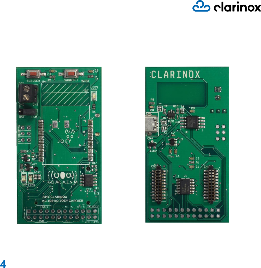
Figure 1: WMI Carrier
WMI Carrier Block Diagram
The block diagram below shows the interconnection and the functionality of different modules on WMI
Carrier board.
User Manual
Page 8
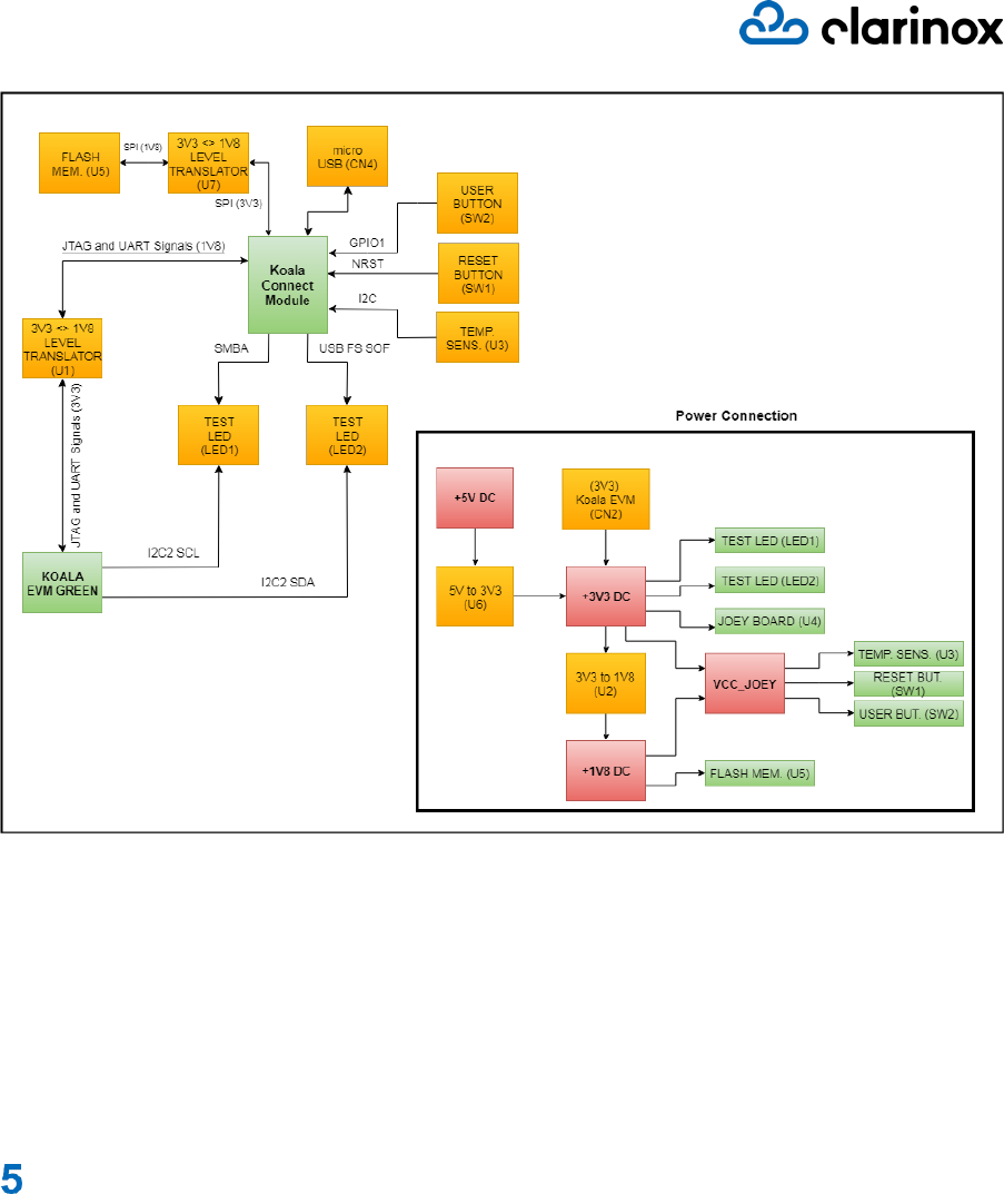
Figure 2: WMI Carrier Block Diagram
• Both KM-1412xx and KM-1531xx Joey® modules can be assembled onto KC-008104 WMI
Carrier board since the Joey® wireless modules consist of the same compatible pinouts.
• WMI Carrier facilitates the Joey®s by extending those pinouts into more convenient test
points. Please refer to KM-1412xx and KM-1531xx Joey® modules user manuals for more
details about their pinouts.
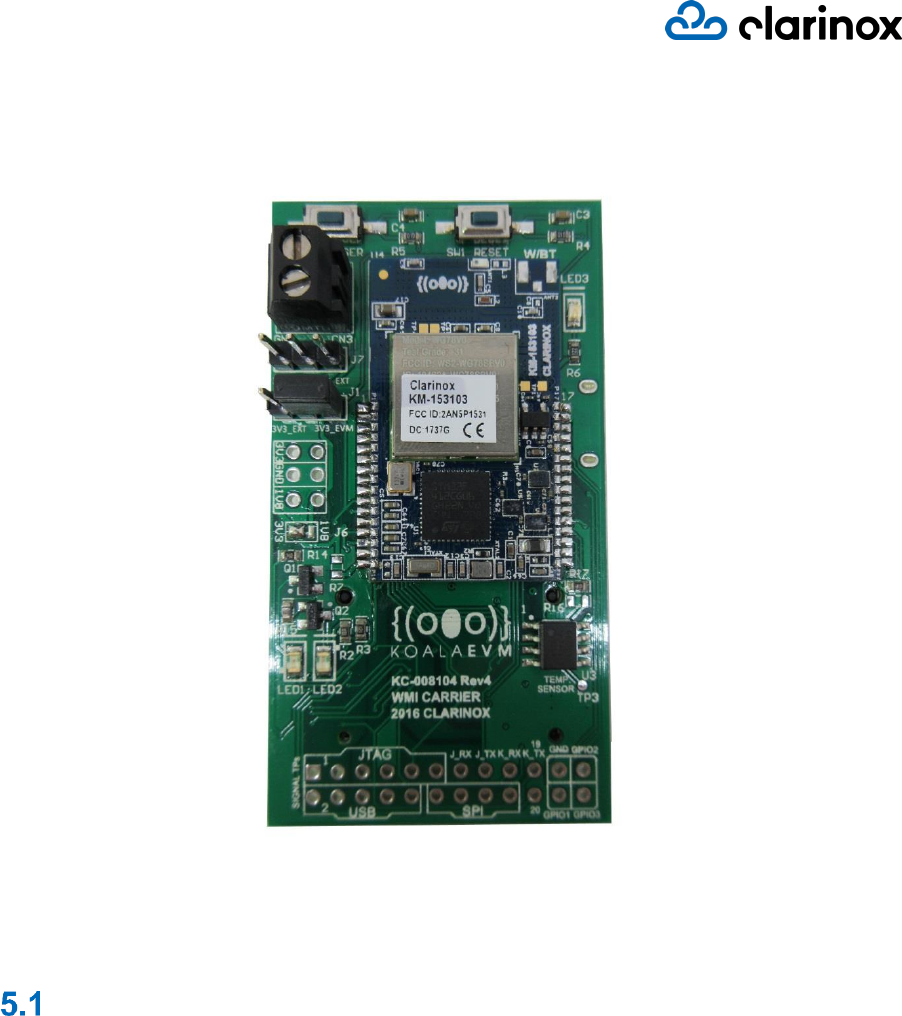
Using with KM-153103 Koala® Connect Module
Following figure shows KM-153102 Joey® module assembled on KC-008104 WMI Carrier board.
User Manual
Page 9
Figure 3: KM-153103 Wi-Fi/Bluetooth Koala® Connect Module attached to WMI Carrier
KM-153103 Module Certification Details
KM-153103 Koala® Connect module complies with Part 15 of the FCC Rules. Operation is subject to
the following two conditions:
(1) The device may not cause harmful interference and
(2) The device must accept any interference received, including interference that may cause
undesired operation of the device.
Clarinox Technologies declares that the radio equipment type RF module is in compliance with
Directive 2014/53/EU.
The compliance has been verified in the operating frequency band of 2400-2483.5 MHz. Developers
and integrators that incorporate the KM-153103 Module in any end products are responsible for
obtaining applicable regulatory approvals for such end product.
The KM-153103 has been tested in the 2400 MHz-2483.5 MHz ISM frequency band at 3.3 V with a
maximum peak power of 19.7 dBm EIRP across the temperature range –40°C to +85°C and
tolerance.
5.1.1 Federal Communications Commission (FCC) Statement
User Manual
Page 10
KM-153103 device complies with FCC radiation exposure limits set forth for an uncontrolled
environment. End users must follow the specific operating instructions for satisfying RF exposure
limits. This transmitter must not be co-located or operating in conjunction with any other antenna or
transmitter.
5.1.2 End Product Labelling
KM-153103 module is designed to comply with the FCC statement, FCC ID: 2AN5P1531. The host
system using this module must display a visible label indicating the following text:
"Contains FCC ID: 2AN5P1531"
Important Notice to OEM Integrators
This module is limited to OEM installation ONLY.
This module is limited to installation in mobile or fixed applications, according to FCC Part 2.1091(b).
The separate approval is required for all other operating configurations, including portable
configurations with respect to FCC Part 2.1093 and different antenna configurations
For FCC Part 15.31 (h) and (k): The host manufacturer is responsible for additional testing to verify
compliance as a composite system. When testing the host device for compliance with Part 15 Subpart
B, the host manufacturer is required to show compliance with Part 15 Subpart B while the transmitter
module(s) are installed and operating. The modules should be transmitting and the evaluation should
confirm that the module's intentional emissions are compliant (i.e. fundamental and out of band
emissions). The host manufacturer must verify that there are no additional unintentional emissions
other than what is permitted in Part 15 Subpart B or emissions are complaint with the transmitter(s)
rule(s).
Antenna Installation
The antenna must be installed such that 20 cm is maintained between the antenna and users,
The transmitter module may not be co-located with any other transmitter or antenna.
The ATN016008LCD2442MA1 antenna with -1.41 dBi gain was verified in the conformity testing.
Radiated transmit power must be equal to or lower than that specified in the FCC Grant of Equipment
Authorization for FCC ID: 2AN5P1531. A separate approval is required for all other antenna type, or
higher gain antenna.
In the event that these conditions cannot be met (for example certain laptop configurations or co-
location with another transmitter), then the FCC authorization is no longer considered valid and the
FCC ID cannot be used on the final product. In these circumstances, the OEM integrator will be
responsible for re-evaluating the end product (including the transmitter) and obtaining a separate FCC
authorization.
Manual Information to the End User
The OEM integrator has to be aware not to provide information to the end user regarding how to
install or remove this RF module in the user’s manual of the end product which integrates this module.
The end user manual shall include all required regulatory information/warning as show in this manual.
Federal Communication Commission Interference
Statement
This equipment has been tested and found to comply with the limits for a Class B digital device,
pursuant to part 15 of the FCC Rules. These limits are designed to provide reasonable protection
against harmful interference in a residential installation. This equipment generates, uses and can
radiate radio frequency energy and, if not installed and used in accordance with the instructions, may
cause harmful interference to radio communications. However, there is no guarantee that
interference will not occur in a particular installation. If this equipment does cause harmful
interference to radio or television reception, which can be determined by turning the equipment off
and on, the user is encouraged to try to correct the interference by one of the following measures:

User Manual
Page 11
- Reorient or relocate the receiving antenna.
- Increase the separation between the equipment and receiver.
- Connect the equipment into an outlet on a circuit different from that to which the receiver is
connected.
- Consult the dealer or an experienced radio/TV technician for help.
Any changes or modifications not expressly approved by the party responsible for compliance could
void the user's authority to operate this equipment. This transmitter must not be co-located or
operating in conjunction with any other antenna or transmitter.
Radiation Exposure Statement
This equipment complies with FCC radiation exposure limits set forth for an uncontrolled environment.
This equipment should be installed and operated with minimum distance 20 cm between the radiator
& your body.

User Manual
Page 12
Interfaces
Interface to the koala® evm Green
• The WMI carrier board KC-008104 acts as an interface between the Wireless Joey® module
and the koala® evm Green.
• The Joey® wireless modules can be soldered on top of the WMI carrier board which is then
fitted on to the WMI connectors on the koala® evm Green board.
• The koala® evm WMI interface provides power, JTAG programming support and IOs
including USART and I2C to Joey® Modules via WMI Carrier.
The table below describes WMI Carrier to koala® evm Green connector pins which contain signals
from the koala® evm board.
Pin (WMI Carrier)
Function (koala® evm Green)
Function (STM32F41X)
7 – CN1
USART6 TX
USART1 RX
8 – CN1
USART6 RX
USART1 TX
11 – CN1
I2C2 SCL
12 – CN1
I2C2 SDA
14 – CN1
JTAG TDO
JTAG TDO
15 – CN1
JTAG TDI
JTAG TDI
16 – CN1
JTAG TMS
JTAG TMS
17 – CN1
JTAG TCK
JTAG TCK
18 – CN1
JTAG NRST
JTAG NRST
19 – CN1
JTAG JNRST
JTAG JNRST
13 – CN2
3.3V
Power Supply
15 – CN2
GND
GND
16 – CN2
GND
GND
17 – CN2
GND
GND
18 – CN2
GND
GND
Table 1: WMI Carrier to koala® evm Interface
Please refer to koala® evm Green and Joey® module user manuals for more details. Following figure
shows WMI Carrier with Joey® module attached to koala® evm Green
User Manual
Page 13
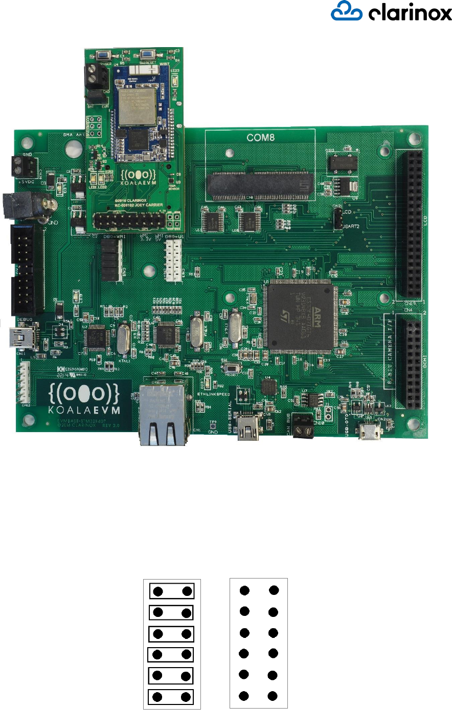
Figure 4: WMI Carrier Mounted on koala® evm Green
6.1.1 Programming the Joey® Modules on WMI Carrier
The koala® evm Green features an embedded ST-LINK for programming the Joey® modules and
debugging them. In order to enable this feature, CN22 and CN14 jumpers on the koala® evm must be
configured as following picture.
Figure 5: Jumper Connection on koala® evm Green to Program Joey® Modules on WMI Carrier
CN22
CN14
DBG=WMI
DBG=U1
User Manual
Page 14
Please refer to Joey® module’s user manual for hardware details for programming.
Hardware Details on WMI Carrier
On-board Flash Memory
WMI Carrier consists of 128MB additional flash memory to be used to program Joey®s. The following
table provides information on the Joey® modules’ microcontroller pins required to access the Flash
memory on WMI carrier.
Joey® Module Pin Number
Flash Memory
Microcontroller STM32F41X port
24
SPI MOSI
PA7
25
SPI MISO
PA6
26
SPI SCK
PA5
27
SPI NSS
PA4
Table 2: Flash Memory interface between WMI Carrier and Joey®
On-board Temperature Sensor
The temperature sensor (DS7505S) on WMI Carrier is interfaced via I2C and the following table
provides information on pin/signal connection.
Joey® Module Pin Number
Temperature Sensor
Microcontroller STM32F41X port
30
SDA
PB9
29
SCL
PB8
Table 3: Temperature Sensor interface between WMI Carrier and Joey®
Micro USB Connection
The Micro USB connection on the WMI Carrier is not connected to STM32F41X microcontroller on
Joey® modules by default. In order to use micro USB connection, the resistor pads R8, R11, R12 and
R13 should be connected. Following table provides information on the corresponding pins/ports on
Joey® module microcontroller.
Joey® Module Pin Number
Micro USB
Microcontroller STM32F41X port
11
USB FS DP
PA12
12
USB FS DM
PA11
13
USB FS ID
PA10
14
USB FS VBUS
PA9
15
USB FS SOF
PA8
Table 4: Micro USB interface between WMI Carrier and Joey®
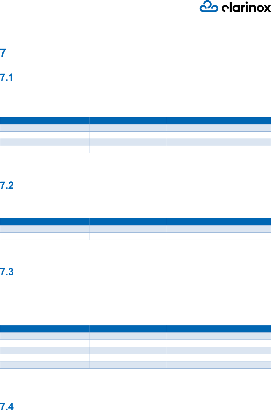
Power Connection
Apart from the 3V3 power supplied by the koala® evm, WMI Carrier consists of an external power
connector to supply power when used as standalone. J1 jumper connection determines the source of
power drawn by WMI Carrier.
User Manual
Page 15
Figure 6: Jumper Connection on WMI Carrier to draw power from koala® evm
Operating Specifications
Below are the ratings of WMI Carrier board under normal operation.
KC-008104
Specification
Value
Unit
Voltage supply
3.3 - 5
V
Current draw (idle)
30
mA
Operating temperature (ambient)
-40 to +85
°C
Storage temperature
-40 to +105
°C
Table 5: KC-008104 Typical Operating Conditions
J1
BAT
EVM