Clarinox Technologies 1531 Koala Connect User Manual Module
Clarinox Technologies Pty Ltd Koala Connect Module
Contents
- 1. User Manual Host
- 2. User Manual Module
User Manual Module

Clarinox Technologies Pty. Ltd.
ABN 89 062 954 170
28 / 296 Bay Rd
Cheltenham VIC 3192
Tel (613) 9095 8088
www.clarinox.com
KM-153103 koala® connect (aka Joey®)
DATASHEET
The information contained herein shall not be disclosed to unauthorized persons. This document remains the
property of Clarinox Technologies Pty Ltd. It contains proprietary and confidential information and is considered to
be a trade secret by Clarinox Technologies Pty Ltd. No information contained herein is to be shared, copied,
disclosed, or otherwise compromised in any way without the written consent of Clarinox Technologies Pty Ltd. The
contents of this document are subject to change without notice. Clarinox Technologies Pty Ltd reserves the right
to make changes in this document as progress in planning, development, engineering or manufacturing warrants.
All Rights Reserved, Copyright Clarinox Technologies Pty Ltd © 2018

KM-153103 Datasheet
Page 1
Revision History
Revision
Date
Designed by
Approved by
Description
1.0
08 May 2018
ND
GT
Initial draft
1.1
15 June 2018
ND
GT
FCC Certification warning details added
KM-153103 Datasheet
Page 2
Table of Contents
Highlights ................................................................................................................................ 4
Product Description ................................................................................................................ 4
Module Certification Details ........................................................................................... 5
1.2.1.1 Federal Communications Commission (FCC) Statement ............................................ 5
1.2.1.2 End Product Labelling ................................................................................................. 5
Important Notice to OEM Integrators ............................................................................ 5
Antenna Installation ........................................................................................................ 6
Manual Information to the End User .............................................................................. 6
Federal Communication Commission Interference Statement ...................................... 6
Radiation Exposure Statement ....................................................................................... 7
Product Selector ...................................................................................................................... 8
Module Pinouts ....................................................................................................................... 8
Hardware Interfaces ............................................................................................................... 9
Bluetooth Signals Hardware Details ..................................................................................... 10
WiFi Signals Hardware Details .............................................................................................. 10
Block Diagram ....................................................................................................................... 11
Features ................................................................................................................................ 11
Microcontroller ..................................................................................................................... 12
Software Features ................................................................................................................. 12
Package (Dimensions) ........................................................................................................... 14
Environmental Data, Quality & Reliability ............................................................................ 14
Electrical Characteristics ....................................................................................................... 14
Applications ........................................................................................................................... 15
Pin Compatible Wireless Variants ......................................................................................... 15
Supporting Products ............................................................................................................. 15
Placement Details ................................................................................................................. 16

KM-153103 Datasheet
Page 3
List of Figures
Figure 1: KM-153103 Koala® Connect Module ....................................................................................... 4
Figure 2: Module Pinouts ........................................................................................................................ 8
Figure 3: KM-153103 Module Block Diagram ....................................................................................... 11
Figure 4: Placement Details .................................................................................................................. 16
List of Tables
Table 1: Product Selector ........................................................................................................................ 8
Table 2: Module Pinouts ......................................................................................................................... 9
Table 3: Bluetooth Signals Hardware Details ........................................................................................ 10
Table 4: WiFi Signals Hardware Details ................................................................................................. 10
KM-153103 Datasheet
Page 4
Highlights
• Complies with Part 15 of the FCC Rules
• Wi-Fi & dual-mode Bluetooth
• Supports custom Bluetooth Low Energy profiles and services
• On-board Wi-Fi + Bluetooth antennas
• Micro access point
• High speed iAP & iAP2 support
• Embedded Wi-Fi and Bluetooth stack
• Use directly with final design or prototype on koala® evm with Clarinox Carrier boards. (KC-
0181xx, KC-0081xx)
Product Description
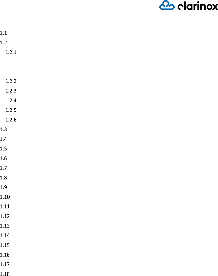
Figure 1: KM-153103 Koala® Connect Module
Joey® Wi-Fi® + Bluetooth® modules are compact all-in-one standalone modules featuring Wi-Fi WLAN
/ Wi-Fi Direct, Bluetooth Classic and Bluetooth Low Energy. When used in conjunction with koala®
evm, the Joey® modules provide a stable environment to ease the integration of wireless technologies
into a project. The modules feature Texas Instruments’ WL183xMOD variants with Wi-Fi and
Bluetooth coexistence and STM32F412CG on-board processor to drive the user application in addition
to supporting the wireless protocols. Flexibility of wireless technology is provided with version 4.1
Bluetooth Classic, Bluetooth Low Energy, WLAN and Wi-Fi Direct with IEEE802.11a/b/g/n standards
supported.
Joey® modules will help shorten the development time, reduce development costs and open the door
to new possibilities for wireless device features. Joey® modules may be used stand-alone products
with no additional hardware required; or used in conjunction with other hardware. Additional sensors
can be connected directly to the module via GPIO, ADC, I2C, SPI and UART.

KM-153103 Datasheet
Page 5
Module Certification Details
KM-153103 Koala® Connect module complies with Part 15 of the FCC Rules. Operation is subject to
the following two conditions:
(1) This device may not cause harmful interference and
(2) This device must accept any interference received, including interference that may cause
undesired operation.
Clarinox Technologies declares that the radio equipment type RF module is in compliance with
Directive 2014/53/EU.
The compliance has been verified in the operating frequency band of 2400-2483.5 MHz. Developers
and integrators that incorporate the KM-153103 Module in any end products are responsible for
obtaining applicable regulatory approvals for such end product.
The KM-153103 has been tested in the 2400 MHz-2483.5 MHz ISM frequency band at 3.3 V with a
maximum peak power of 19.7 dBm EIRP across the temperature range –40°C to +85°C and tolerance.
1.2.1.1 Federal Communications Commission (FCC) Statement
This module complies with FCC radiation exposure limits set forth for an uncontrolled environment.
End users must follow the specific operating instructions for satisfying RF exposure limits. This
transmitter must not be co-located or operating in conjunction with any other antenna or
transmitter.
1.2.1.2 End Product Labelling
This module is designed to comply with the FCC statement, FCC ID: 2AN5P1531. The host system
using this module must display a visible label indicating the following text:
"Contains FCC ID: 2AN5P1531"
Important Notice to OEM Integrators
This module is limited to OEM installation ONLY.
This module is limited to installation in mobile or fixed applications, according to FCC Part 2.1091(b).
The separate approval is required for all other operating configurations, including portable
configurations with respect to FCC Part 2.1093 and different antenna configurations
For FCC Part 15.31 (h) and (k): The host manufacturer is responsible for additional testing to verify
compliance as a composite system. When testing the host device for compliance with Part 15
Subpart B, the host manufacturer is required to show compliance with Part 15 Subpart B while the
transmitter module(s) are installed and operating. The modules should be transmitting and the
evaluation should confirm that the module's intentional emissions are compliant (i.e. fundamental
and out of band emissions). The host manufacturer must verify that there are no additional
unintentional emissions other than what is permitted in Part 15 Subpart B or emissions are
complaint with the transmitter(s) rule(s).

KM-153103 Datasheet
Page 6
Antenna Installation
The antenna must be installed such that 20 cm is maintained between the antenna and users,
The transmitter module may not be co-located with any other transmitter or antenna.
The ATN016008LCD2442MA1 antenna with -1.41 dBi gain was verified in the conformity testing.
Radiated transmit power must be equal to or lower than that specified in the FCC Grant of
Equipment Authorization for FCC ID: 2AN5P1531. A separate approval is required for all other
antenna type, or higher gain antenna.
In the event that these conditions cannot be met (for example certain laptop configurations or co-
location with another transmitter), then the FCC authorization is no longer considered valid and the
FCC ID cannot be used on the final product. In these circumstances, the OEM integrator will be
responsible for re-evaluating the end product (including the transmitter) and obtaining a separate
FCC authorization.
Manual Information to the End User
The OEM integrator has to be aware not to provide information to the end user regarding how to
install or remove this RF module in the user’s manual of the end product which integrates this
module. The end user manual shall include all required regulatory information/warning as show in
this manual.
Federal Communication Commission Interference
Statement
This equipment has been tested and found to comply with the limits for a Class B digital device,
pursuant to part 15 of the FCC Rules. These limits are designed to provide reasonable protection
against harmful interference in a residential installation. This equipment generates, uses and can
radiate radio frequency energy and, if not installed and used in accordance with the instructions,
may cause harmful interference to radio communications. However, there is no guarantee that
interference will not occur in a particular installation. If this equipment does cause harmful
interference to radio or television reception, which can be determined by turning the equipment off
and on, the user is encouraged to try to correct the interference by one of the following measures:
- Reorient or relocate the receiving antenna.
- Increase the separation between the equipment and receiver.
- Connect the equipment into an outlet on a circuit different from that to which the receiver is
connected.
- Consult the dealer or an experienced radio/TV technician for help.
Any changes or modifications not expressly approved by the party responsible for compliance could
void the user's authority to operate this equipment. This transmitter must not be co-located or
operating in conjunction with any other antenna or transmitter.

KM-153103 Datasheet
Page 7
Radiation Exposure Statement
This equipment complies with FCC radiation exposure limits set forth for an uncontrolled
environment. This equipment should be installed and operated with minimum distance 20 cm
between the radiator & your body.
KM-153103 Datasheet
Page 8
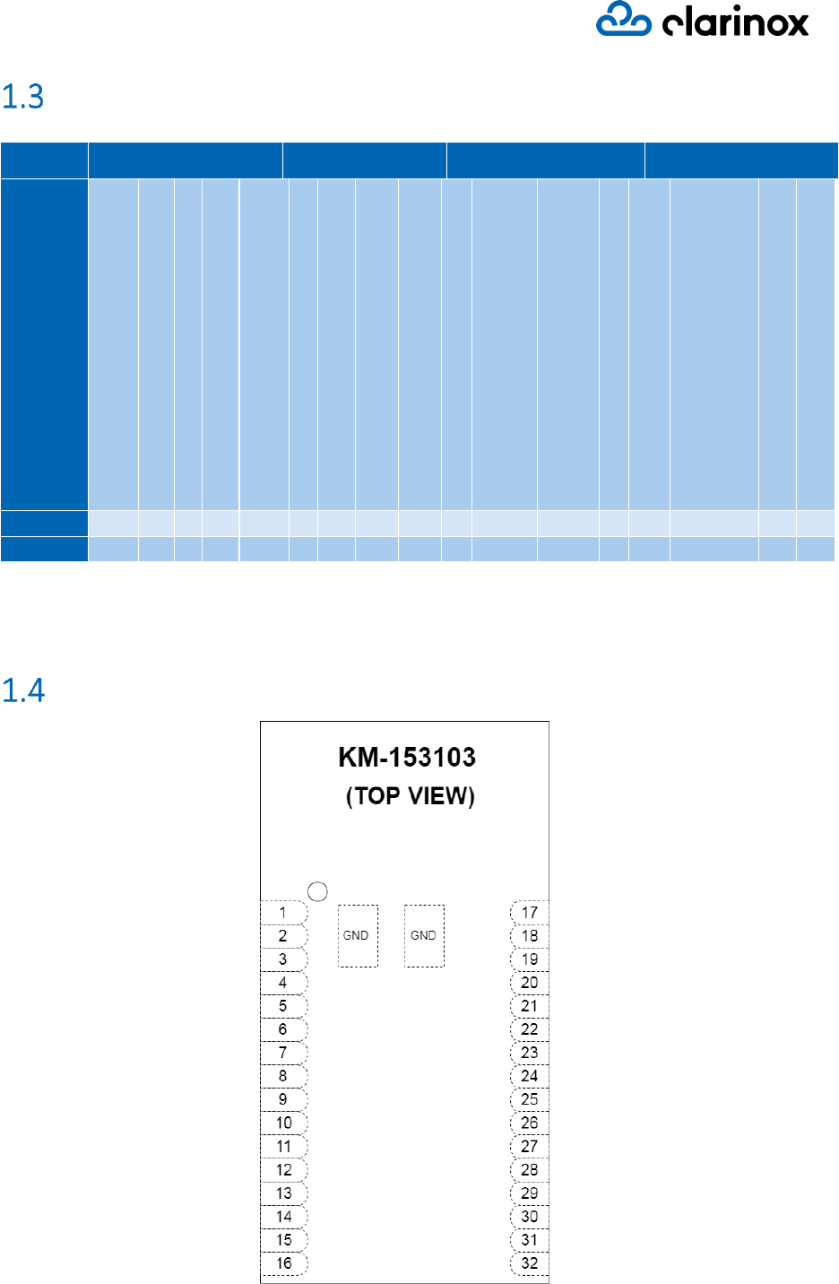
Product Selector
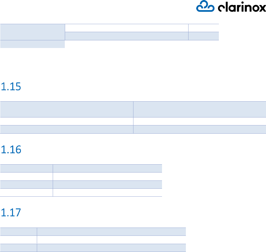
Table 1: Product Selector
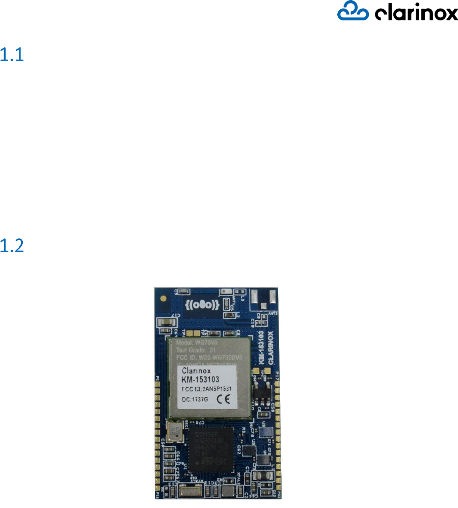
Module Pinouts
Figure 2: Module Pinouts
Model
Radio
Interfaces
Power
Package
Bluetooth Qualification
Bluetooth Classic and Low Energy
WiFi
Antenna Type
Max Number of Connections
UART
SPI and I2C
GPIO Pins
ADC Channels
Power Supply: 3.3V
Current Draw (Idle)
Current Draw (TX)
I/O Voltage: 1.8V
Solder Pins
Dimensions (W x L x H) mm
Support KC-0181xx Joeyduino Carrier Board
Support KC-0081xx WMI Carrier Board
KM-153103
V4.1
✓
✓
I
6-10
1
1
21
10
✓
60mA
90mA
✓
32
20x34x3
✓
✓
KM-141202
V4.1
✓
x
I
6-10
1
1
23
10
✓
30mA
50mA
✓
32
20x30x3.5
✓
✓
KM-153103 Datasheet
Page 9
PIN
FUNCTION
SOURCE/TARGET
PORT DETAILS
P1
AUD_IN
WL1831
AUD_IN (PCM)
P2
AUD_OUT
WL1831
AUD_OUT (PCM)
P3
AUD_CLK
WL1831
AUD_CLK (PCM)
P4
AUD_FSYNC
WL1831
AUD_FSYNC (PCM)
P5
JTAG_TMS
STM32F412
PA13 (JTAG)
P6
JTAG _TCK
STM32F412
PA14 (JTAG)
P7
JTAG _TDI
STM32F412
PA15 (JTAG)
P8
JTAG _TDO
STM32F412
PB3 (JTAG)
P9
JTAG _JNRST
STM32F412
PB4 (JTAG)
P10
JTAG _NRST
STM32F412
NRST (JTAG)
P11
USB_FS_DP
STM32F412
PA12 (USB FS/OTG)
P12
USB_FS_DM
STM32F412
PA11 (USB FS/OTG)
P13
USB_FS_ID
STM32F412
PA10 (USB FS/OTG)
P14
USB_FS_VBUS
STM32F412
PA9 (USB FS/OTG)
P15
USB_FS_SOF
STM32F412
PA8 (USB FS/OTG)
P16
VBAT
STM32F412
VDD (1V8)
P17
GND
STM32F412
VSS (GND)
P18
GND
STM32F412
VSS (GND)
P19
3V3
Power Supply
3V3
P20
3V3
Power Supply
3V3
P21
GPIO_1
STM32F412
PB0 (GPIO)
P22
GPIO_2
STM32F412
PB1 (GPIO)
P23
NC
P24
SPI1_MOSI
STM32F412
PA7 (SPI)
P25
SPI1_MISO
STM32F412
PA6 (SPI)
P26
SPI1_SCK
STM32F412
PA5 (SPI)
P27
SPI1_NSS
STM32F412
PA4 (SPI)
P28
I2C1_SMBA
STM32F412
PB5 (I2C)
P29
I2C1_SCL
STM32F412
PB8 (I2C)
P30
I2C1_SDA
STM32F412
PB9 (I2C)
P31
USART1_TX
STM32F412
PB6 (USART)
P32
USART1_RX
STM32F412
PB7 (USART)
Table 2: Module Pinouts
Hardware Interfaces
SPI
1 (4 pins)
I2C
1 (3 pins)
UART
1 (2 pins)
PCM
1 (4 pins)
GPIO pins
16*
ADC channels
6
KM-153103 Datasheet
Page 10
Bluetooth Signals Hardware Details
WiLink8 Bluetooth module
Microcontroller STM32F412 port
BT EN (Bluetooth Enable)
PC13 (Output)
HCI RTS
PA0
HCI CTS
PA1
HCI RX
PA2
HCI TX
PA3
Table 3: Bluetooth Signals Hardware Details
WiFi Signals Hardware Details
Table 4: WiFi Signals Hardware Details
WiLink8 WiFi module
Microcontroller STM32F412 port
WL_EN (Wi-Fi Enable)
PB2 (Output)
WL_IRQ (Wi-Fi IRQ)
PB10 (Interrupt)
SPI MISO
PB14
SPI CLK
PB13
SPI MOSI
PB15
SPI CS
PB12
KM-153103 Datasheet
Page 11
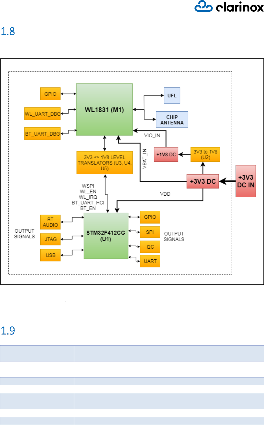
Block Diagram
Figure 3: KM-153103 Module Block Diagram
Features
Wi-Fi & Bluetooth
module
TI WL1831MOD
Wi-Fi standards
IEEE 802.11a/b/g/n, Wi-Fi Direct Concurrent Operation (Multichannel,
Multirole)
Wi-Fi bands
2.4 GHz
Wi-Fi roles
STA, AP, Wi-Fi Direct
Wi-Fi maximum
throughput
TCP: 80 Mbps
UDP: 100 Mbps
Wi-Fi MIMO
2x2 MIMO
Bluetooth modes
V4.1 BR + EDR (Classic Bluetooth with EDR)
KM-153103 Datasheet
Page 12
v4.1 LE (Bluetooth Low Energy)
Output power
Wi-Fi: +17.3 dBm (@ 1 Mbps DSSS)
Classic Bluetooth:
BR: +11.7 dBm (GFSK)
EDR: +7.2 dBm
Bluetooth LE: +7.0 dBm
Sensitivity
Wi-Fi: -96.3 dBm (@ 1 Mbps DSSS)
Classic Bluetooth: -92.2 dBm (GFSK)
Bluetooth LE: -92.2 dBm
Antenna
Internal antenna
Microcontroller
STM32F412CG
Core: ARM® 32-bit Cortex®-M4
Package: UFQFPN48
CPU: 100 MHz
SRAM: 256 Kbytes
Flash: 1 Mbyte
Software Features
Embedded software
ClarinoxBlue Bluetooth Stack
ClarinoxBlue Bluetooth Low Energy Stack
ClarinoxWiFi WLAN Stack
(all combinations of the above three are possible)
Combined IPv4 and limited IPv6 stack
Supported Interfaces:
➢ UART
➢ I2C
➢ SPI
➢ USB
Wi-Fi Security
WEP 64/128
WPA and WPA2
TKIP and AES/CCMP hardware accelerator
LEAP, PEAP, EAT-TLS
Wi-Fi operational
modes
Access Point(AP) mode
Station mode
P2P (Wi-Fi Direct)
Bluetooth Classic
Profiles & Protocols
Profiles:
➢ AVRCP Controller 1.5
➢ A2DP Source | Sink 1.3
➢ DID 1.3
➢ FTP Client | Server 1.1
➢ GAVDP Initiator | Acceptor | Delay Reporting Initiator 1.3
➢ GOEP 1.1
➢ HDP Source | Sink 1.1
➢ HFP AG | HF 1.7
➢ HID 1.1 General HID Host
➢ HSP AG | HS 1.2

KM-153103 Datasheet
Page 13
➢ IOP
➢ MAP 1.1 Messaging Client Equipment (MCE)
➢ MPS 1.0
➢ OPP Client | Server 1.1
➢ PAN User
➢ PBAP Client 1.2
➢ Report Protocol | HID Device Role 1.1
➢ SPP DevA| DevB 1.2
Protocols:
➢ AVCTP Controller 1.4
➢ AVDTP Source | Sink | Initiator | Acceptor 1.3
➢ BNEP
➢ GAP (Generic Access Profile)– BR/EDR/LE
➢ MCAP Source | Sink
➢ OBEX 1.1
➢ OBEX over RFCOMM 1.1
➢ RFCOMM 1.1
➢ SDP (Service Discovery Protocol) Server | Client
Bluetooth Low Energy
Profiles & Protocols
Profiles:
➢ ANP Server | Client 1.0
➢ BAS Profile over LE
➢ BLP Sensor (Server) | Collector (Client)
➢ CPP Collector 1.0
➢ CSCP Sensor (Server) | Collector (Client)
➢ CTS Profile over LE 1.0
➢ DIS profile over LE 1.1
➢ FMP Target (Server) | Locator (Client)
➢ GLP Sensor (Server) | Collector (Client)
➢ HIDS Profile over LE
➢ HOGP Device (Server) 1.0
➢ HRP Sensor (Server) | Collector (Client)
➢ HRS Profile over LE
➢ HTP Thermometer (Server) | Collector (Client)
➢ IAS Profile over LE
➢ LNP Sensor (Server) | Collector (Client) 1.0
➢ PASP Server
➢ PXP Reporter (Server) 1.0
➢ RSCP Sensor (Server)
➢ TIP Server
Protocols:
➢ ATT (Attribute Protocol) Client
➢ BPP (Basic Printing Profile) 1.2 Printer | Sender
➢ BIP (Basic Imaging Profile) 1.2 Image Push Initiator | Image Push
Responder | Image Pull Initiator | Image Pull Responder
➢ CTN (Calendar, Tasks and Notes Profile)
➢ GAP (Generic Access Profile)– BR/EDR/LE
➢ GATT (Generic Attribute Profile) over LE Client | Server
➢ HCRP (Hardcopy Cable Replacement Profile) 1.2
KM-153103 Datasheet
Page 14
Bluetooth Security
Secure Simple Pairing
128-bit AES encryption
BLE Secure Connection
Max. number of
connections
Wi-Fi 2.4 GHz: Up to 8 connections
Classic Bluetooth: Up to 7 connections
Bluetooth LE: Up to 10 connections
Single/Dual processor
Approach
User applications can be implemented on koala® connect with Clarinox
WiFi / Bluetooth classic and low energy protocol stacks running on the
same single CPU. Dual CPU approach is also possible by having Clarinox
stacks implemented on koala® connect and user application running on
a separate CPU. Using Joey® in both these approaches enhances IO
capability in the system.
Simultaneous Wireless
usage
Classic Bluetooth, Bluetooth Low Energy and Wi-Fi technologies can be
used simultaneously and gateway functionality (simultaneous roles)
amongst these technologies are possible
API Interface
Host to module connection supports Request-Response based
implementation
UART, I2C, SPI interfaces supported
Applications can be simulated using a desktop environment
Supported Wi-Fi modes
AP, Station and P2P modes are supported
Simultaneous nodes such as AP and Station are supported
iOS connectivity
iAP & iAP2
Package (Dimensions)
Dimensions
(W × L × H)
20 mm x 34 mm x 3 mm
Weight
< 2.0 g
Mounting
Solder edge pins with castellation (visually inspectable)
Environmental Data, Quality & Reliability
Operating temperature
-10 °C to +60 °C
Storage temperature
-40 °C to +85 °C
Electrical Characteristics
Supply voltage
3.3 V
I/O voltage
1.8 V
Average Power consumption
0.15W
Current draw
(Bluetooth)
Idle*
33mA
Bluetooth Stack initialization
33mA
Searching for devices
60mA
Current draw (Wi-Fi)
WiFi Stack initialization
90mA
Start interface as Station
90mA
Idle as Station
60mA
Connect to Wi-Fi network as Station
110mA
Start interface as Access Point (AP)
95mA
KM-153103 Datasheet
Page 15
Idle as Access Point
60mA
Connect to device as AP
160mA
*Idle current is measured after Bluetooth is initialized while no any other functions are carried out.
The current draw values in above table are the total current drawn by the Joey® module when
connected to Clarinox Joeyduino Carrier.
Applications
Internet of Things (IoT)
Consumer Electronics, Home Automation,
Wearables
Industrial IoT
Industrial Automation
Health
Medical/Health devices
Pin Compatible Wireless Variants
KM-153103-1831
2.4 GHz Wi-Fi and Bluetooth
KM-153103-1837
5 GHz and 2.4 GHz Wi-Fi and Bluetooth
KM-153103-1801
2.4 GHz Wi-Fi only
KM-153103-1807
5 GHz and 2.4 GHz Wi-Fi only
Supporting Products
KC-0181xx
Joeyduino Carrier / Breakout Board for Joey® modules
KC-0081xx
WMI Carrier / Breakout Board for Joey® modules
KM-9805xx
Sensor Board with 9D sensor and haptic driver
KM-153103 Datasheet
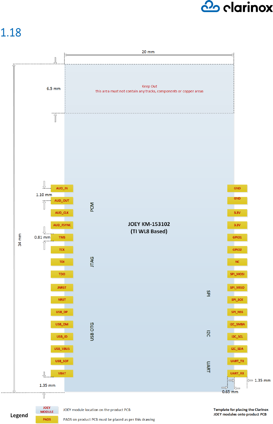
Page 16
Placement Details
Figure 4: Placement Details