Clarion 0608136 Car equipment unit User Manual
Clarion Co., Ltd Car equipment unit
UserManual.wiki
>
Clarion
>
0608136 User Manual
user manual
Navigation menu
Upload a User Manual
Namespaces
Wiki Guide
HTML
PDF
Info
Views
User Manual
Discussion / Help
Navigation
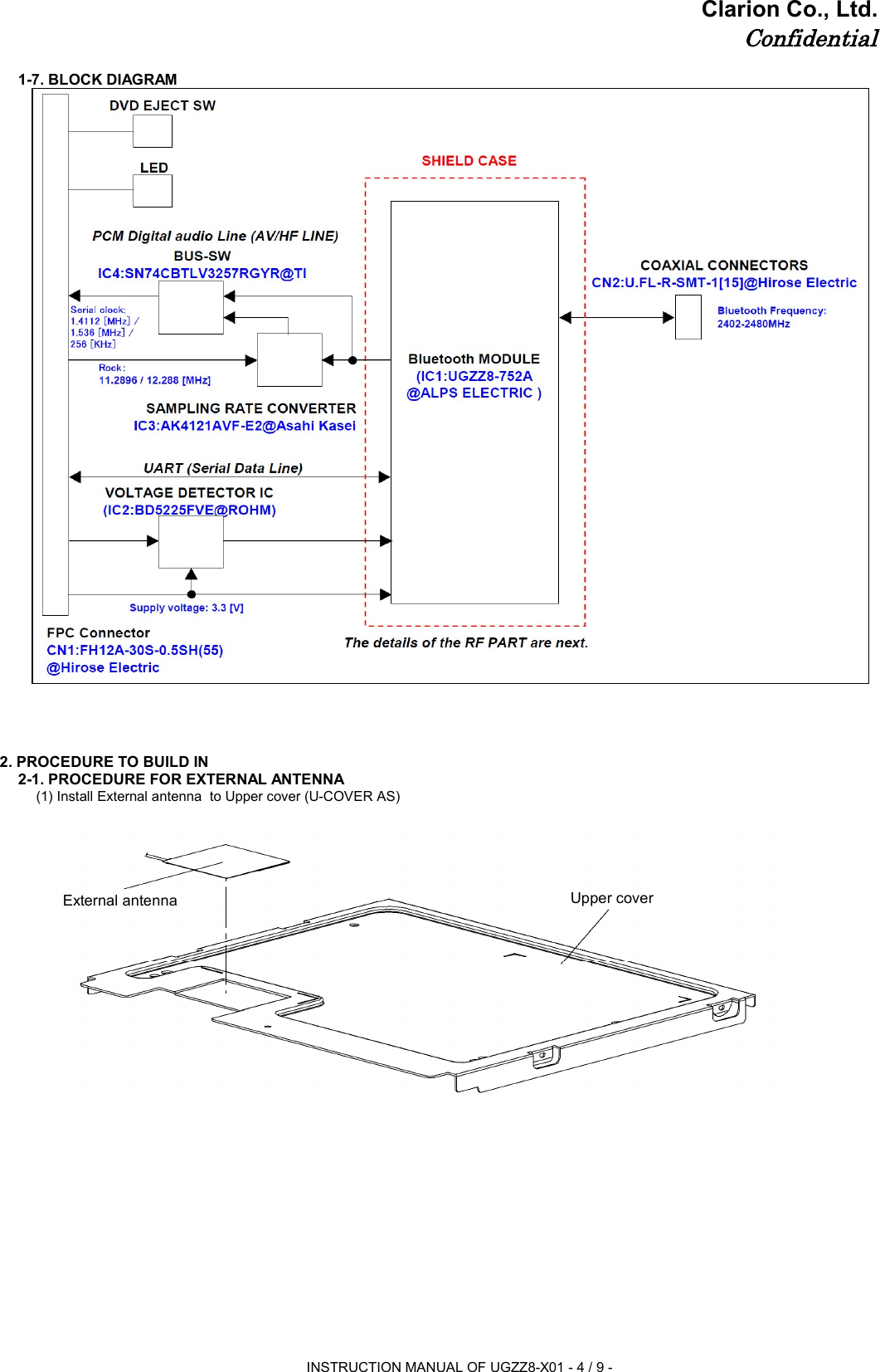
![Clarion Co., Ltd.ConfidentialINSTRUCTION MANUAL OF UGZZ8-X011. BLUETOOTH MODULE SPECIFICATION1-1. PRODUCT NAMEUGZZ8-X011-2. MANUFACTURER ALPS ELECTRIC1-3. FEATURESBluetooth™ Specification V2.0+EDR supportComplete type of Bluetooth module, built-in various profileBuilt-in Link controller, Link Manager ProtocolOutput Power class2 compliantType with a chip antennaFull custom package with pwb can be fit to only navigation products made by ClarionBuilt-in Flash memory(16Mbit), system clock 26MHz(OSC)B to B connector interface1-4. SPECIFICATION1-4-1. MECHANICAL SPECIFICATION1-4-1-1. EXTERNAL DIMENSIONS Refer to the following page.BluetoothModuleALPSELECTRICOn-Board Lug TerminalETOOG-RRF COAXIAL CONNECTORHIROSE ELECTRICU. FL-R-SMT-1[15]FPC ConnectorHIROSE ELECTRICFH12-30S-0.5SH[55]FPC Connectorterminal No.Tact SwitchALPS ELECTRICSKRPABE010ROHMSML-311DTT86J2INSTRUCTION MANUAL OF UGZZ8-X01 - 1 / 9 -](https://usermanual.wiki/Clarion/0608136/User-Guide-1664526-Page-1.png)
![Clarion Co., Ltd.Confidential1-4-1-2. MASS10.17 [g] (Typ.)1-4-2. ELECTRIC SPECIFICATION1-4-2-1. POWER-SUPPLY-VOLTAGE DC +3.1 to +3.6 [V]1-4-2-2. TEMPERATURE RANGE-40 to +85 [degree C]1-4-3. RF SPECIFICATION1-4-3-1. NORMAL TRANSMIT POWER(AVERAGED POWER)-6 to +4 [dBm]1-4-3-2. REFERENCE SENSITIVITY LEVEL(BER=0.001%)MAX. -70 [dBm]1-5. LABEL INFORMATION1-5-1. LABEL LAYOUTModel NumberClarionPartsLot Number001WWDA1609LabelIC: 419C-0608136Model: UGZZ8-X01INSTRUCTION MANUAL OF UGZZ8-X01 - 2 / 9 -](https://usermanual.wiki/Clarion/0608136/User-Guide-1664526-Page-2.png)
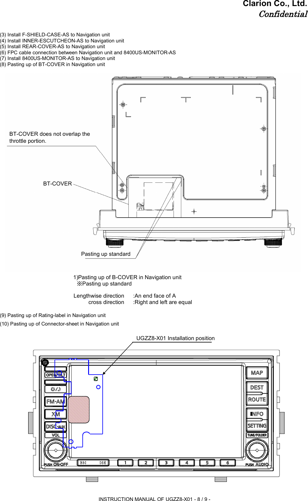
![Clarion Co., Ltd.Confidential1-5-2. CONTENTS OF LABEL1-6. CONNECTOR PIN ASSIGNMENT21GND-Ground20GND-Ground19UART_RXIUART_RX18UART_TXOUART_TX23GND-Ground22GND-Ground17UART_CTSIUART_CTSGND-Ground16UART_RTSOUART_RTSNO.PIN NAMENO.2GND-1GND-4PIO[2] (PTE5)O3PIO[0] (PTB1)O6NC-5PIO[1] (PTE0)O8NC-7NC-10PCM_CLKO9GND-12PCM_INI11PCM_SYNCO24ILL-I13PCM_OUTO14CLK11/12MI1526DVD_EJECTO25ILL+I28NC-27RST#I30VCCI29VCCIDESCRIPTIONGroundGroundAV Master Clock Select(44.1kHz=Low, 48kHz=High)PCM_MutePCM_Reset(Active Low), DAC PwrDown(PwrDown Enable=Low)NCNCNCGroundAudio ClockAudio ClockAV/HF InputAudio ClockLED SignalLED SignalAV Master clock InputPower Supply 3.3VDISC Eject SignalReset (Active Low )NCPower Supply 3.3VFPC Connector terminal NO.301Model NumberRev. NumberClarion PartsLot NumberTELEC Mark & IDCompany NameFCC ID & IC IDA001WWDA1609060-8136-01SJ20608136IC:419C-0608136Model: UGZZ8-X01INSTRUCTION MANUAL OF UGZZ8-X01 - 3 / 9 -](https://usermanual.wiki/Clarion/0608136/User-Guide-1664526-Page-3.png)