user manual
Clarion Co., Ltd.
Confidential
INSTRUCTION MANUAL OF UGZZ8-X01
1. BLUETOOTH MODULE SPECIFICATION
1-1. PRODUCT NAME
UGZZ8-X01
1-2. MANUFACTURER
ALPS ELECTRIC
1-3. FEATURES
Bluetooth
™
Specification V2.0+EDR support
Complete type of Bluetooth module, built-in various profile
Built-in Link controller, Link Manager Protocol
Output Power class2 compliant
Type with a chip antenna
Full custom package with pwb can be fit to only navigation products made by Clarion
Built-in Flash memory(16Mbit), system clock 26MHz(OSC)
B to B connector interface
1-4. SPECIFICATION
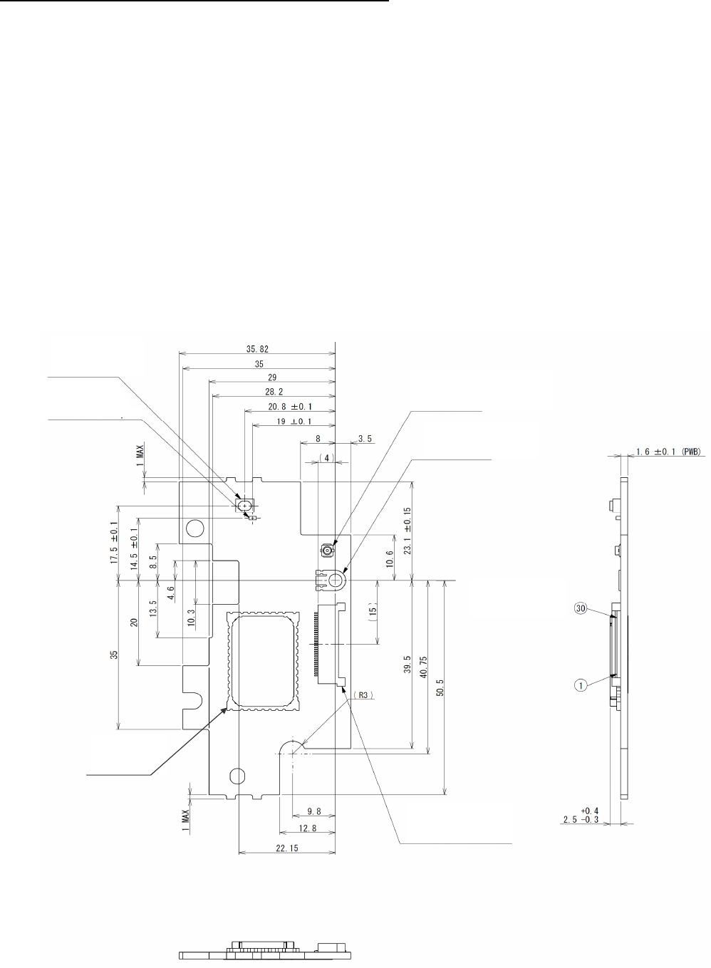
1-4-1. MECHANICAL SPECIFICATION
1-4-1-1. EXTERNAL DIMENSIONS
Refer to the following page.
Bluetooth
Module
ALPS
ELECTRIC
On-Board Lug Terminal
ETO
OG-R
RF COAXIAL CONNECTOR
HIROSE ELECTRIC
U. FL-R-SMT-1[15]
FPC Connector
HIROSE ELECTRIC
FH12-30S-0.5SH[55]
FPC Connector
terminal No.
Tact Switch
ALPS ELECTRIC
SKRPABE010
ROHM
SML-
311DTT86J2
INSTRUCTION MANUAL OF UGZZ8-X01 - 1 / 9 -
Clarion Co., Ltd.
Confidential
1-4-1-2. MASS
10.17 [g] (Typ.)
1-4-2. ELECTRIC SPECIFICATION
1-4-2-1. POWER-SUPPLY-VOLTAGE
DC +3.1 to +3.6 [V]
1-4-2-2. TEMPERATURE RANGE
-40 to +85 [degree C]
1-4-3. RF SPECIFICATION
1-4-3-1. NORMAL TRANSMIT POWER(AVERAGED POWER)
-6 to +4 [dBm]
1-4-3-2. REFERENCE SENSITIVITY LEVEL(BER=0.001%)
MAX. -70 [dBm]
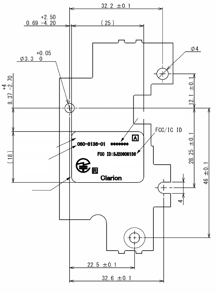
1-5. LABEL INFORMATION
1-5-1. LABEL LAYOUT
Model Number
Clarion
Parts
Lot Number
001WWDA1609
Label
IC: 419C-0608136
Model: UGZZ8-X01
INSTRUCTION MANUAL OF UGZZ8-X01 - 2 / 9 -
Clarion Co., Ltd.
Confidential
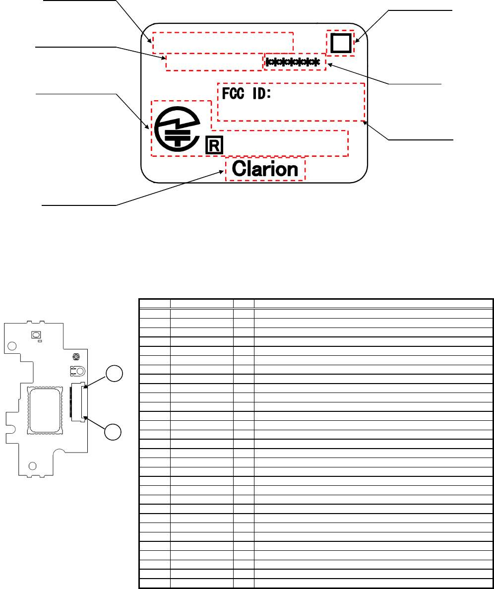
1-5-2. CONTENTS OF LABEL
1-6. CONNECTOR PIN ASSIGNMENT
21
GND
-
Ground
20
GND
-
Ground
19
UART_RX
I
UART_RX
18
UART_TX
O
UART_TX
23
GND
-
Ground
22
GND
-
Ground
17
UART_CTS
I
UART_CTS
GND
-
Ground
16
UART_RTS
O
UART_RTS
NO.
PIN NAME
NO.
2
GND
-
1
GND
-
4
PIO[2] (PTE5)
O
3
PIO[0] (PTB1)
O
6
NC
-
5
PIO[1] (PTE0)
O
8
NC
-
7
NC
-
10
PCM_CLK
O
9
GND
-
12
PCM_IN
I
11
PCM_SYNC
O
24
ILL-
I
13
PCM_OUT
O
14
CLK11/12M
I
15
26
DVD_EJECT
O
25
ILL+
I
28
NC
-
27
RST#
I
30
VCC
I
29
VCC
I
DESCRIPTION
Ground
Ground
AV Master Clock Select(44.1kHz=Low, 48kHz=High)
PCM_Mute
PCM_Reset(Active Low), DAC PwrDown(PwrDown Enable=Low)
NC
NC
NC
Ground
Audio Clock
Audio Clock
AV/HF Input
Audio Clock
LED Signal
LED Signal
AV Master clock Input
Power Supply 3.3V
DISC Eject Signal
Reset (Active Low )
NC
Power Supply 3.3V
FPC Connector terminal NO.
30
1
Model Number
Rev. Number
Clarion Parts
Lot Number
TELEC Mark & ID
Company Name
FCC ID & IC ID
A
001WWDA1609
060-8136-01
SJ20608136
IC:419C-0608136
Model: UGZZ8-X01
INSTRUCTION MANUAL OF UGZZ8-X01 - 3 / 9 -
Clarion Co., Ltd.
Confidential
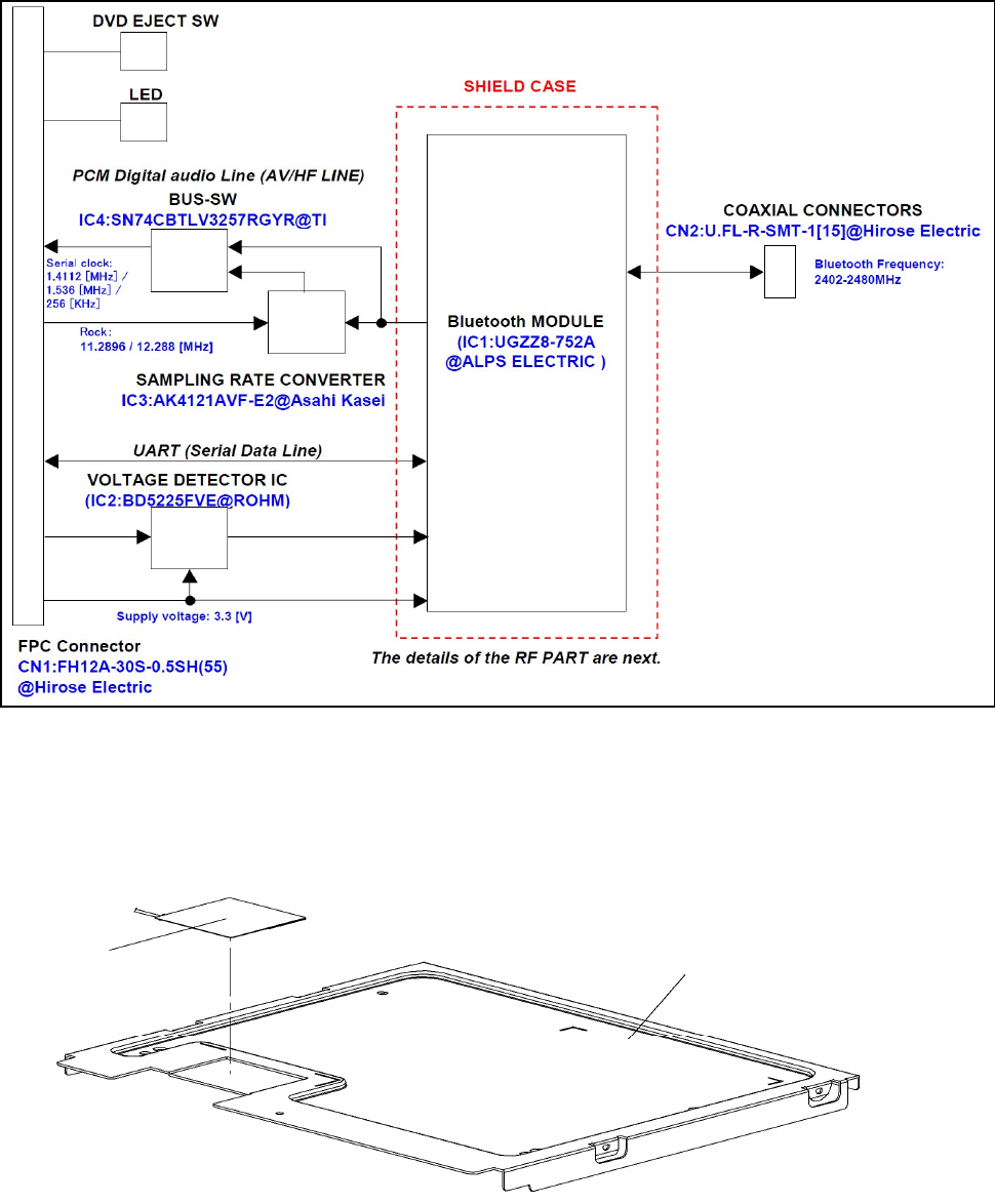
1-7. BLOCK DIAGRAM
2. PROCEDURE TO BUILD IN
2-1. PROCEDURE FOR EXTERNAL ANTENNA
(1) Install External antenna to Upper cover (U-COVER AS)
Upper cover
External antenna
INSTRUCTION MANUAL OF UGZZ8-X01 - 4 / 9 -
Clarion Co., Ltd.
Confidential
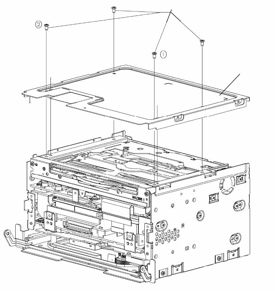
(2) Install U-COVER AS to Navigation unit
1)Be careful so that a cable is not tucking
2)Tighten up a screw in order of one to two ( In addition, it is random order )
Screw
U-COVER AS
INSTRUCTION MANUAL OF UGZZ8-X01 - 5 / 9 -
Clarion Co., Ltd.
Confidential
2-2. PROCEDURE FOR UGZZ8-X01
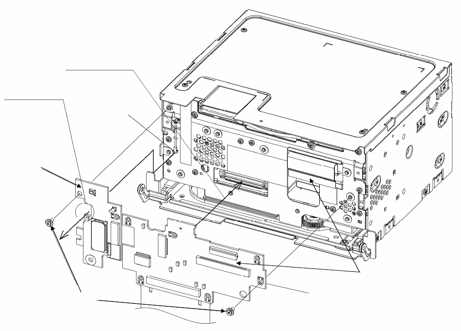
(1) Install UGZZ8-X01 to Navigation unit
1)Install UGZZ8-X01 with a screw
※
Take out an external antenna from a notch part
2)Install FSWA with a screw
3)Connected FSWA in order of 40pin-FFC cable, 80pin-FFC cable
※
firmly-lock the FFC connector
BtoB connection
UGZZ8-X01
FSWA PCB
Navigation unit
FPC cable connection
Screw
External antenna
A notch
INSTRUCTION MANUAL OF UGZZ8-X01 - 6 / 9 -
Clarion Co., Ltd.
Confidential
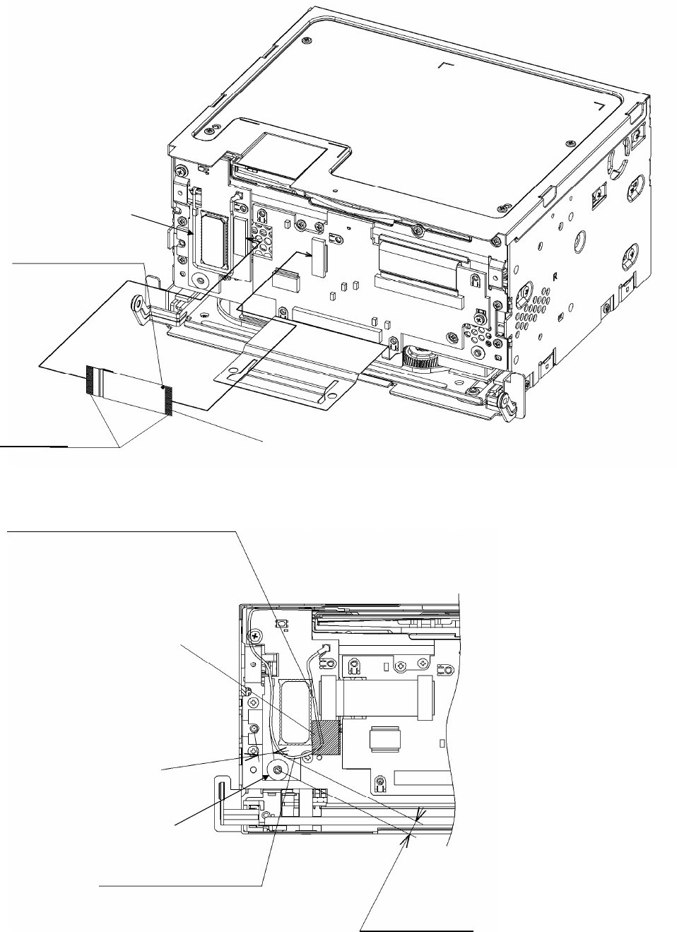
(2)Connect External antenna to UGZZ8-X01 , FPC cable connection between UGZZ8-X01 and FSWA PCB
1)Connect the dot mark side to FSWA PCB
※
firmly-lock the
FFC
connector
2)connect a cable as follows. After placement , fix it in TAPE-DV1.
Navigation unit
External
A dot mark
Point of contact side
30pin FFC cable
Arrange a cable between
BT module IC and FPC connector
TAPE-DV1
More than 4
More than 4.5
External antenna
A cable do not be arranged
on a white print part
INSTRUCTION MANUAL OF UGZZ8-X01 - 7 / 9 -
Clarion Co., Ltd.
Confidential
(3) Install F-SHIELD-CASE-AS to Navigation unit
(4) Install INNER-ESCUTCHEON-AS to Navigation unit
(5) Install REAR-COVER-AS to Navigation unit
(6) FPC cable connection between Navigation unit and 8400US-MONITOR-AS
(7) Install 8400US-MONITOR-AS to Navigation unit
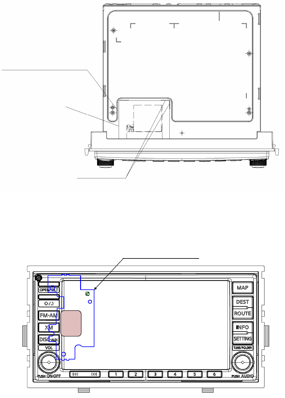
(8) Pasting up of BT-COVER in Navigation unit
1)Pasting up of B-COVER in Navigation unit
※
Pasting up standard
Lengthwise direction :An end face of A
cross direction :Right and left are equal
(9) Pasting up of Rating-label in Navigation unit
(10) Pasting up of Connector-sheet in Navigation unit
BT-COVER
Pasting up standard
BT-COVER does not overlap the
throttle portion.
UGZZ8-X01 Installation position
INSTRUCTION MANUAL OF UGZZ8-X01 - 8 / 9 -
Clarion Co., Ltd.
Confidential
3. NOITCE
Avis
3-1. General information
-Please note that this users manual should not be provided to end-users.
3-2. FCC Regulatory Information
-This device complies with part 15 of the FCC Rules. Operation is subject to the following two conditions:
(1) this device may not cause interference, and
(2) this device must accept any interference, including interference that may cause undesired operation.
-The following sentence has to be displayed on the outside of the device in which the module is installed:
"Contains Transmitter Module FCC ID: SJ20608136", or "Contains FCC ID: SJ20608136"
-Any changes or modifications not expressly approved by the party responsible for compliance could void
the user's authority to operate the equipment.
-This equipment complies with FCC RF radiation exposure limits set for an controlled enviornment.
-The antenna used for this transmitter must not be co-located or operating in conjunction
with any other antenna or transmitter.
3-3. Canada Regulatory Information
-This device complies with Industry Canada licence-exempt RSS standards. Operation is subject
to the following two conditions:
(1) this device may not cause interference, and
(2) this device must accept any interference, including interference that may cause undesired operation.
-Cet appareil est conforme avec Industrie Canada exempts de licence standard RSS (s).
L‘utilisation de ce dispositif est autorisée seulement aux conditions suivantes:
(1) il ne doit pas produire de brouillage et
(2)l’ utilisateur du dispositif doit étre prêt à accepter tout brouillage radioélectrique reçu,
même si ce brouillage est susceptible de compromettre le fonctionnement du dispositif.
-The following sentence has to be displayed on the outside of the device in which the module is installed:
“Contains Transmitter Module IC: 419C-0608136” or “Contains IC: 419C-0608136”
-La phrase suivante doit être affiché à l’extérieur de l’appareil dans lequel le module est installé:
“Contient Module émetteur IC: 419C-0608136” ou “Contient IC: 419C-0608136”
-This equipment complies with FCC RF radiation exposure limits set for an controlled environment.
-Cet équipement est conforme aux limites d’exposition aux rayonnements RF
de la FCC établies pour un enviornment contrôlée.
INSTRUCTION MANUAL OF UGZZ8-X01 - 9 / 9 -