Clarke Cav 26 Users Manual 71114A.pmd
vacuum26galloncav26 2d4fa5dc-02c4-49b4-b05d-08733b28ff4d Clarke Vacuum Cleaner CAV 26 User Guide |
2015-02-05
: Clarke Clarke-Cav-26-Users-Manual-531140 clarke-cav-26-users-manual-531140 clarke pdf
Open the PDF directly: View PDF ![]() .
.
Page Count: 20
Form No. 71114A 6/06 Printed in the U.S.A.
Vacuum 26 Gallon
Operator's Manual
This book has important information for the use and safe operation of this machine. Failure to read
this book prior to operating or attempting any service or maintenance procedure to your Clarke
American Sanders machine could result in injury to you or to other personnel; damage to the machine
or to other property could occur as well. You must have training in the operation of this machine
before using it. If your operator(s) cannot read this manual, have it explained fully before attempting
to operate this machine.
All directions given in this book are as seen from the operator’s position at the rear of the machine.
For new books write to: Clarke® , 2100 Highway 265, Springdale, Arkansas 72764
READ THIS BOOK

Page -2- Clarke® American Sanders Operator's Manual - CAV 26
Table of Contents
Important Safety Instructions .................................................................................... 3
Specifications ......................................................................................................... 4
Introduction and Instructions ..................................................................................... 4
Operating Instructions.............................................................................................. 6
Troubleshooting....................................................................................................... 8
Section II Parts and Service Manual
Frame Assembly Drawing ....................................................................................... 10
Frame Assembly Parts List ..................................................................................... 11
Container Unit Assembly Drawing ........................................................................... 12
Container Unit Assembly Parts List ......................................................................... 13
Suction Unit Assembly Drawing ............................................................................... 14
Suction Unit Assembly Parts List ............................................................................. 15
Filter Group Assembly Drawing and Parts List......................................................... 16
Control Panel Assembly Drawing and Parts List ...................................................... 17
Electrical Schematic ............................................................................................... 18

Page -3-
Clarke® American Sanders Operator's Manual - CAV 26
DANGER: Failure to read and observe all DANGER statements could result in severe
bodily injury or death. Read and observe all DANGER statements found in
your Operator's Manual and on your machine.
WARNING: Failure to read and observe all WARNING statements could result in injury
to you or to other personnel; property damage could occur as well. Read
and observe all WARNING statements found in your Operator's Manual and
on your machine.
CAUTION: Failure to read and observe all CAUTION statements could result in damage
to the machine or to other property. Read and observe all CAUTION
statements found in your Operator's Manual and on your machine.
READ ALL INSTRUCTIONS BEFORE USE
WARNING: To reduce the risk of fire, electric shock, or injury:
- Use only as described in this manual. Use only manufacturers recommended attachments.
- For indoor dry pick-up only. Do not expose to rain or weather.
- If machine is not working as it should, has been dropped, damaged, left outdoors, or dropped in water,
return it to a service center.
- Turn off all controls before unplugging
- Do not handle plug or machine with wet hands.
- Do not use with damaged plug or cord.
- Do not unplug by pulling on cord. To unplug, grasp the plug not the cord.
- Do not pull or carry by cord, use cord as a handle, close a door on the cord, or pull cord around sharp
edges or corners. Do not run machine over cord. Keep cord away from heated surfaces.
- Do not leave machine when plugged in. Unplug from outlet when not in use or before servicing.
- Do not put any objects into openings. Do not use with any openings blocked. Keep free of dust, lint,
hair, and anything that may reduce airflow.
- Keep hair, loose clothing, fingers, and body parts away from openings and moving parts.
- Do not use to pick-up flammable or combustible liquids, such as gasoline or solvents. Do not use
where they may be present.
- Do not use to pick-up hot, smoldering, or burning substances.
- Do not use where explosive vapors, such as gas, solvents, alcohol, fuels, or combustible materials such
as grain, wood dust, are present in the air. Keep the work area well ventilated.
- Dust produced from sanding wood or varnish could self ignite causing injury or damage. If this material
has been picked up, empty it immediately after use in a metal container.
- Do not use to pick-up health endangering dust.
- Do not use unless machine is fully assembled. Do not modify the machine. Read all instructional
labels on the machine. Replace damaged labels.
- Do not allow to be used as a toy. Close attention is necessary when used around children.
- Use extra care when cleaning on stairs.
- Connect to properly grounded outlet. See “grounding Instructions”.
- Do not use unless all filtering elements are present. Clean filtering elements frequently.
SAVE THESE INSTRUCTIONS.
IMPORTANT SAFETY INSTRUCTIONS
Page -4- Clarke® American Sanders Operator's Manual - CAV 26
Model CAV 26
Voltage 120 V
Frequency 60 Hz
Power 2400 W (800 x 3)
Ambient Temp -23°F to 86° F
Volume Flow (CFM) 290 (max)
Static Lift (inches H2O) 82
Sound Level dB(A) 73
Cord Length (ft.) 36
Tank Volume 26 gal.
Width (in.) 26
Depth (in.) 27
Height (in.) 61
Weight (lbs.) 143
SPECIFICATIONS
INTRODUCTION AND INSTRUCTIONS
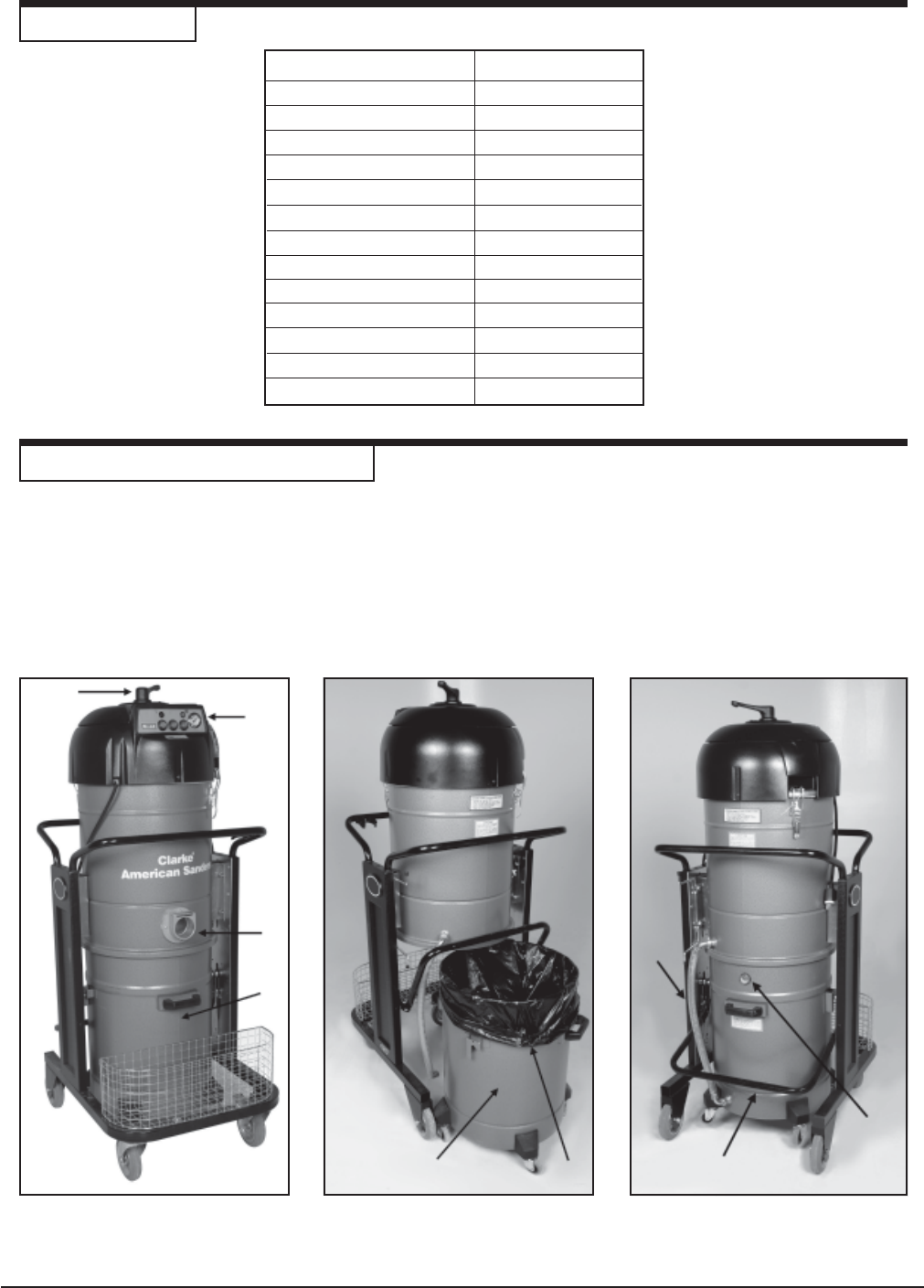
The CAV 26 comes fully assembled. It is specifically designed for dry pick-up of fine dust made from grindings of wood
or gypsum. It is mounted on tough rubber wheels, two of which swivel in order to make the machine easy to handle. It
also has brakes to safely stop the machine in place.
NOTE: When performance has declined noticeably, empty tank and clean the filters accordingly.
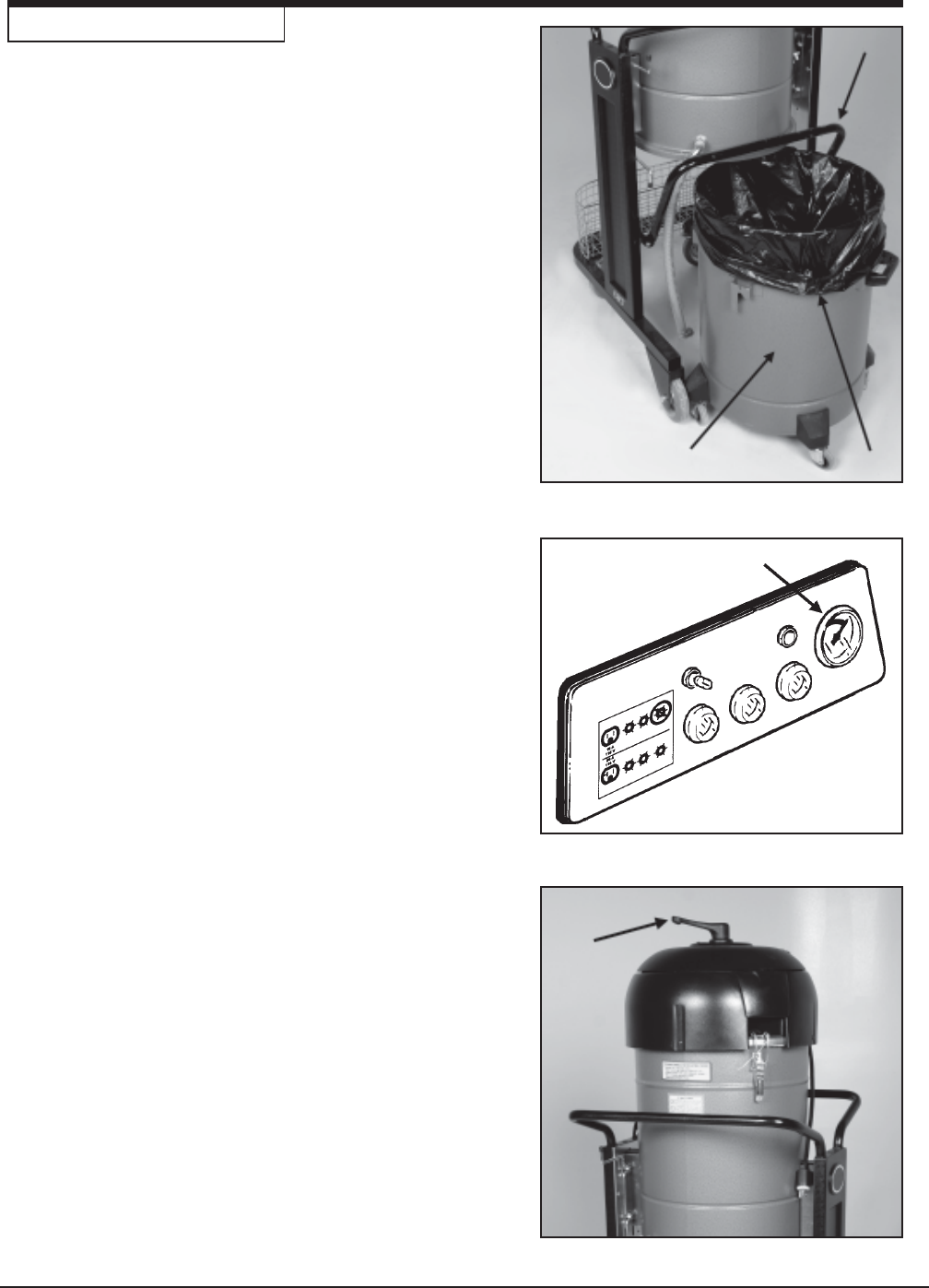
Figure 2Figure 1 Figure 3
4
1
2
3
1
2
3
12
Page -5-
Clarke® American Sanders Operator's Manual - CAV 26
Figure 4
INTRODUCTION AND INSTRUCTIONS, cont.
1
2
34
Features
Figure 1, 1 - Control Panel
For explanation of controls, see "Controls" section this page.
Figure 1, 2 - Inlet
This inlet is for installation of vacuum hose and accessories.
Figure 1, 3 and Figure 2, 1 - Debris Canister
The debris canister should be emptied when the canister is full.
To empty canister, lift debris canister lever (figure 3,2). Debris
canister will lower until it rests with it's wheels on the floor. Grip
the handle and remove the canister, then empty it's contents.
To fit the canister back in place, set it under the vacuum, making
sure the full sight level gauge (figure 3,1) remains visible from the
outside. Then push lever (figure 3,2) downwards, allowing the
canister to lift until it fits against filtering chamber.
Figure 1, 4 - Filter Cleaning Lever
This lever is to used to clean the filter. When manometer (figure
4, 1) reads that the filter is clogged, turn the filter cleaning lever
several times with force in order to shake the dust from the filter.
Do not operate lever with vacuum running.
Wait a few minutes for the dust to settle at the bottom of the
container, then empty.
Figure 3, 1 - Full Sight Level Gauge
This gauge indicates the debris level in the debris canister (figure
1,3). The debris canister should be emptied when it is full.
Before emptying debris canister, switch off the machine by
pressing the vacuum motor switches (figure 4,2) and remove
plug from the power supply.
Figure 3, 2 - Debris Canister Lever
Lift this lever so that debris canister can be removed and emp-
tied. Make sure to lower the lever when you replace the debris
canister.
Figure 3, 3 - Balancing Hose
Balances vacuum around polytank liner (fig 2,2), so it's not
sucked into the filter.
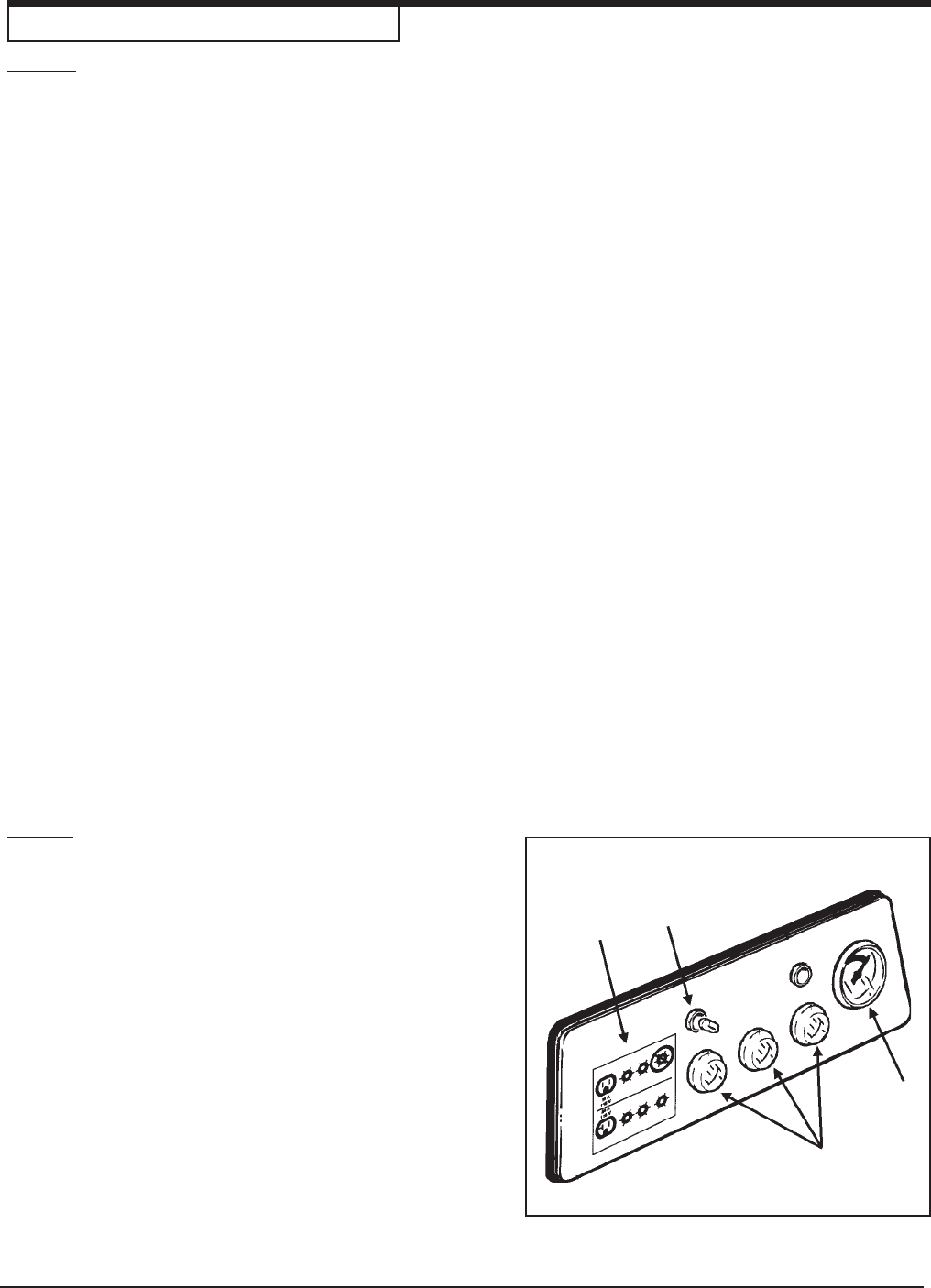
Controls
Figure 4, 1 - Manometer to display filter loading
The vacuum in the filter increases proportionally as the filter
clogs. Then the manometer needle will move from green (filter
good) to the red (filter clogged) section.
Figure 4, 2 - Vacuum Motor Switches
This model is fitted with 3 motors, so it has three vacuum motor
switches on the control panel. Press the switches to start the
vacuum motors. The warning lights (green lights) will come on.
Press the switches again to stop the motors. The warning light
will go out.
Figure 4, 3 - Electrical Label
Figure 4, 4 - Illuminated Mains Voltage Indicator
When on, this indicates that the vacuum is connected to the
electrical supply.
Page -6- Clarke® American Sanders Operator's Manual - CAV 26
OPERATING INSTRUCTIONS
To operate this machine follow these procedures:
1. Position the CAV 26 in a convenient location near
a wall outlet and within reach of the working area.
If the surface is not level, set the brakes on the
casters.
CAUTION: Do not use an extension cord with
the CAV 26 or you will experience a loss in
performance. Should an extension cord be
necessary, use one sized 12 AWG and no
longer than 50' in length. An extension cord
sized smaller than 12 AWG or greater than 50'
in length will overheat and potentially cause a
fire.
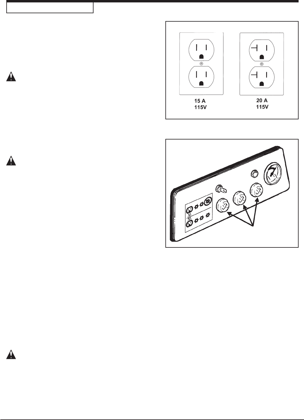
2. Connect the CAV 26 to a wall outlet matching one
of the two shown in figure 5. No adaptor should be
used with this appliance.
WARNING: This appliance must be grounded.
Should an electrical malfunction occur, the
grounding conductors provide a path to
harmful current. Do not connect this
appliance to any other wall outlet than one of
those shown in figure 5. Consult an
electrician if there is reason to doubt that the
wall outlet is not wired correctly. Do not
remove the grounding pin on the power cord.
Do not use this appliance with a damaged
power cord or plug.
3. The CAV 26 uses three individually activated
vacuum motors that allow tailoring the delivery for
the available electrical supply and application.
For Light Duty Applications:
Activate one of the three vacuums. To activate a
vacuum motor, push one of the three vacuum motor
switches (see figure 6). To deactivate the vacuum
motor, push the vacuum switch a second time.
For Heavy Duty Applications or Multiple
Simultaneous Users:
Activate two of the vacuum motors if you are
connected to a 15A wall outlet. You may activate
all three vacuum motors if you are connected to a
20A wall outlet.
WARNING: Do not activate all three vacuum
motors if you are connected to a 15A wall
outlet or you will overload the circuit. An
overloaded circuit will overheat and
potentially cause a fire. Always deactivate the
vacuum motor(s) before disconnecting the
power cord.
Figure 5
Figure 6
Page -7-
Clarke® American Sanders Operator's Manual - CAV 26
OPERATING INSTRUCTIONS
4. Install a poly-liner (fig. 7, 1) in the debris canister
(fig. 7, 2). To release the debris canister raise
the lever (fig. 7, 3) as shown.. The poly-liner
provides quick convenient disposal.
5. When the debris canister becomes full, the
manometer (fig. 8, 1) reads in the red,
deactivating all vacuum motors.
6. Allow time for the dust to settle, then operate the
filter cleaning lever (fig. 9, 1) several times.
7. Remove the poly-liner and replace with a new
liner.
8. Replace the debris canister. To fit the canister
back in place, set it under the vacuum and push
the lever downwards. This allows the canister to
lift until it fits against the filtering chamber.
3
1
2
Figure 7
Figure 8
Figure 9
1
1

Page -8- Clarke® American Sanders Operator's Manual - CAV 26
ActionCause
Problem
1. Check whether power is reaching the socket.
Check whether the plug and cable are in good
condition.
Ask for assistance from an authorized service
technician.
1. Shake the filter. Replace it if this is not sufficient.
2. Check the suction hose / wand and clean it.
1. Replace it with another with identical character-
istics.
2. Replace it with another with suitable
characteristics.
1. Remove and replace the carbon brushes.
1. Check all ground connections. Especially check
the suction inlet fitting.
Lastly, the hose must be strictly antistatic.
1. No power.
1. Clogged primary filter.
2. Suction hose clogged.
1. The filter is torn.
2. Inadequate filter.
1. Worn or broken carbon brushes.
1. Nonexistent or ineffective grounding.
The vacuum fails to start
The rpm rate of the vacuum
increases.
Dust leaks from the machine.
Noisy vacuum motors
Electrostatic current on the
vacuum.
TROUBLESHOOTING

Page -9-
Clarke® American Sanders Operator's Manual - CAV 26
Section II
Parts and Service
(71114A)
Page -10- Clarke® American Sanders Operator's Manual - CAV 26
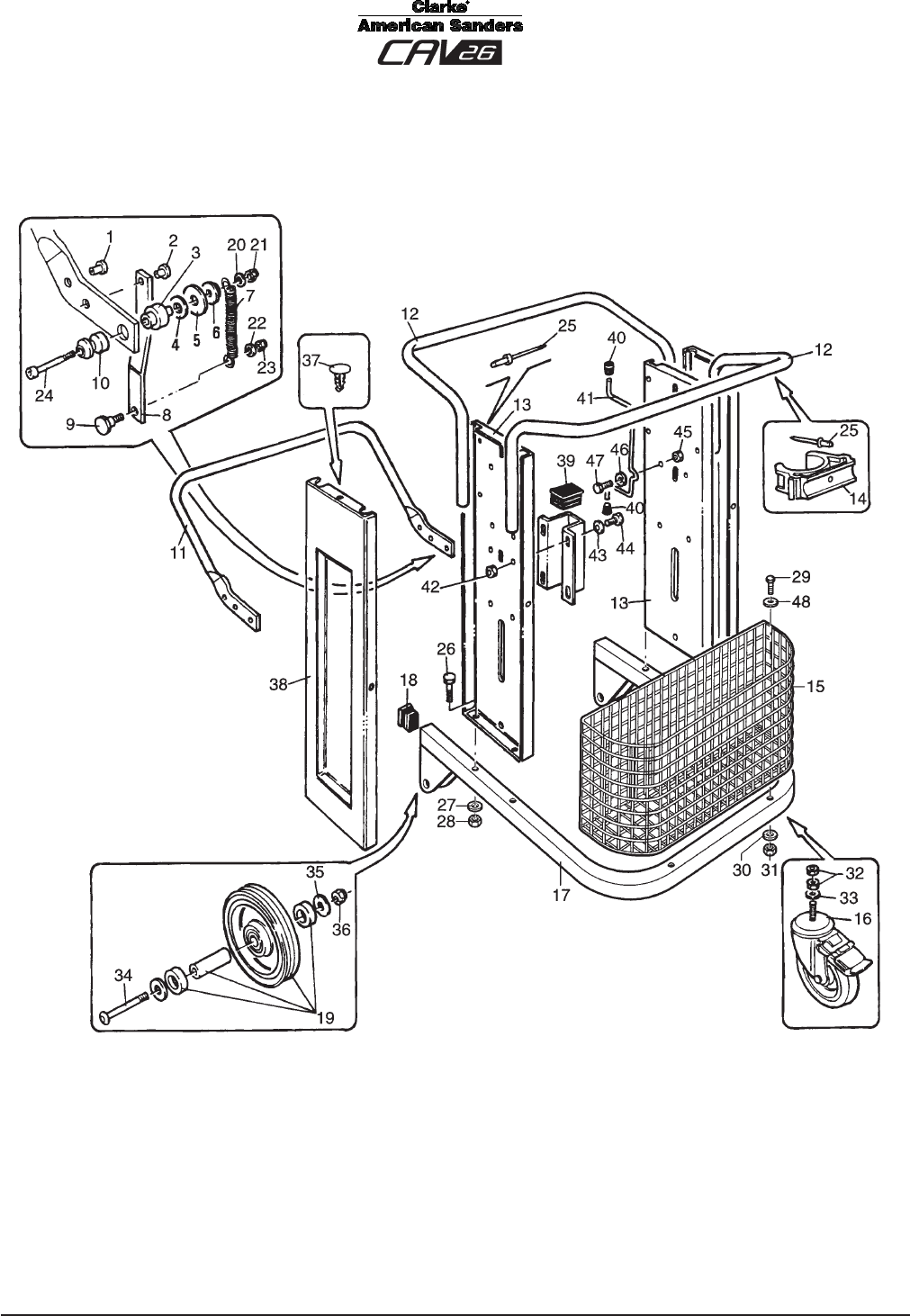
Frame Assembly Drawing 2/06
Page -11-
Clarke® American Sanders Operator's Manual - CAV 26
Frame Assembly Parts List 5/06
Ref. Part No. Description Qty
1 8 14087 Pin 2
2 8 14084 Pin 2
3 8 14262 Pin 2
4 8 38033 Washer 2
5 8 38034 Washer 2
6 8 14266 Washer 2
7 8 14267 Spring 2
8 8 14256 Lever 2
9 8 14261 Pin 2
10 8 14259 Bushing 2
11 8 14258 Lever 1
12 8 18513 Handgrip 2
13 8 18506 Pillar 2
14 8 40392 Collar 1
15 8 16060 Basket 1
16 8 40582 Caster, Cart 2
17 8 36196 Cart 1
18 8 40035 Plug 2
19 8 40581 Wheel, Cart 2
20 229102 Washer, Ø 8 2
21 80312A Nut, M8 Block 2
22 229102 Washer, Ø 8 2
23 80312A Nut, M8 Block 2
24 58050A Screw, M8 x 65 Soc. 2
25 83002A Rivet, Ø 6,4 x 15 9
26 98456A Screw, M8 x 50 4
27 229102 Washer, Ø 8 4
28 80163A Nut, M8 4
29 80314A Screw, M8 x 65 4
30 229102 Washer, Ø 8 4
31 80163A Nut, M8 4
32 920936 Nut, M12 2
33 980648 Washer, Ø 12 2
34 80315A Screw, M10 x 65 2
35 229044 Washer, Ø 10 2
36 80162A Nut, M10 2
37 8 38038 Rivet 6
38 8 16380 Side-Piece 2
39 8 40396 Plug 2
40 8 40407 Push Rod 2
41 8 16177 Cable Support 1
42 80163A Nut, M8 4
43 229102 Washer, Ø 8 6
44 964058 Screw, M8 x 16 6
45 80163A Nut, M8 4
46 980205 Washer, Ø 8 x 24 2
47 1803337 Screw, M8 x 25 2
48 229102 Washer, Ø 8 4
Page -12- Clarke® American Sanders Operator's Manual - CAV 26
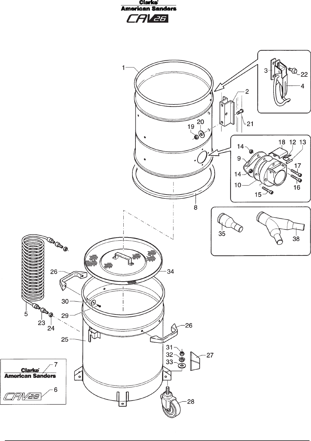
Container Unit Assembly Drawing 2/06
Page -13-
Clarke® American Sanders Operator's Manual - CAV 26
Container Unit Assembly Parts List 3/06
Ref. Part No. Description Qty
1 Ref. Container 1
2 Ref. Bracket 2
3 Ref. Plaque 2
4 8 36028 Latch 2
5 5 60133 Hose, Balancing 1
6 Ref. Label 1
7 Ref. Label 1
8 8 17007 Seal, Inlet
9 8 12013 Deflector 1
10 8 17006 Seal, Container 1
11 Ref. Filler 1
12 Ref. Spring 2
13 Ref. Pin, Ø 3 x 16 2
14 924004 Nut, M5 4
15 58413A Screw, M5 x 20 1
16 58411A Screw, M5 x 25 2
17 58414A Screw, M5 x 30 1
18 Ref. Push Button 1
19 80312A Nut, M8 Block 4
20 424033 Washer, Ø 8 x 32 4
21 964058 Screw, M8 x 16 4
22 80214A Screw, M6 x 12 4
23 8 40881 Reducer, M6 x 8 2
24 8 40187 Ring Nut 2
25 830331CS Debris Canister Asm
(Includes 23-33)
1
26 8 40771 Handle 2
27 8 17021 Bumper 4
28 8 40001 Wheel 4
29 964058 Screw, M8 x 16 4
30 229102 Washer, Ø 8 4
31 920936 Nut, M12 4
32 87101A Washer, Ø 12 4
33 980648 Washer, Ø 12 4
34 8 31221 Grid 1
35 722001 Inlet Fitting 1
38 7 22064 Inlet Splitter 1
Ref. Items 1 - 24 = Part No. 8 31687CS, Complete Container, Qty. 1
Ref. Items 11, 12, 13, 18 = Part No. 8 32178, Complete Inlet Asm., Qty. 1
Page -14- Clarke® American Sanders Operator's Manual - CAV 26
Suction Unit Assembly Parts List 2/06
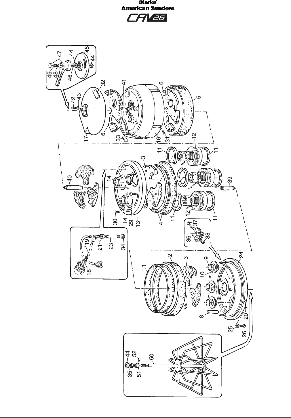
Page -15-
Clarke® American Sanders Operator's Manual - CAV 26
Suction Unit Assembly Parts List 6/06
Ref. Part No. Description Qty
1 - 6 8 17324 Soundproofing Kit 1
8 8 14270 Spacer 2
9 8 12168 Valve 3
10 8 13162 Valve Seat 3
11 8 17325 Seal 6
12 8 54006 Vacuum Motor 3
NI839067.115 Carbon Brush for ref. 12 (2 reqd.) ea.
13 8 16179 Motor Locator 1
14 8 17326 Seal 3
16 8 16243 Housing, Vacuum Motor 1
17 816381CFM Cover 1
18 8 40401 Hosebarb 1
19 Ref. Tube 0.4m
20 8 38036 Rivet M6 4
21 8 40404 T-Fitting 1
23 8 14271 Spacer 1
24 8 35049 Motor Platform 1
25 980646 Washer, Ø 6 4
26 88208A Screw, M6 x 10 2
29 88208A Screw, M6 x 10 2
30 56446A Screw, 4.8 x 19 6
31 88208A Screw, M6 x 10 4
32 Ref. Label 1
33 Ref. Label 1
34 80162A Nut, M10 1
35 8 14052 Nut 1
36 8 39594 Cable Gland 1
37 80065A Screw, M4 x 8 1
38 920934 Nut, M4 1
39 8 14499 Spacer 1
40 8 14509 Spacer 1
41 8 38036 Rivet, M6 3
42 80214A Screw, M6 x 12 3
43 980646 Washer, Ø 6 x 18 3
44 980679 Washer, Ø 18 4
45 8 16257 Cover 1
46 8 14052 Nut 1
47 8 40583 Lever 1
48 229102 Washer, Ø 8 1
49 80312A Nut, M8 "Block" 1
50 8 33254 Cage 1
51 8 38048 Ring 1
52 80313A Dowel M6 x 10 2
NOTE: indicates a change has been made since the last
publication of this manual.
Page -16- Clarke® American Sanders Operator's Manual - CAV 26
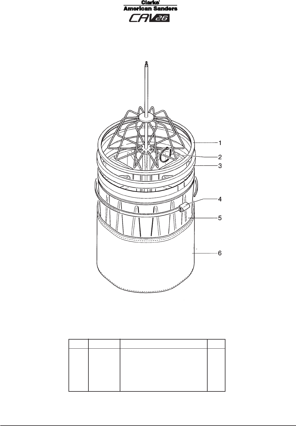
Filter Group Assembly Drawing & Parts List 3/06
Ref. Part No. Description Qty
1 8 17026 Seal 1
2 Ref. Tie 6
3 Ref. Ring 1
4 Ref. Tie 1
5 Ref. Filter 1
6 8 17749 Filter Liner, Polyester 1
Ref. Items 1 - 5 = Part No. 8 33151, Complete Filter, Qty 1
Page -17-
Clarke® American Sanders Operator's Manual - CAV 26
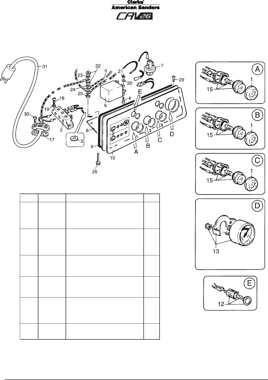
Control Panel Assembly Drawing & Parts List 6/06
Ref. Part No. Description Qty
1 8 39531 Switch Cover 3
2 Ref. Connection Block 1
3 Ref. Label 3
4 80065A Screw, 4 x 10 1
5 Ref. Cables Kit 1
6 8 39533 Suppressor 1
7 8 40403 Pressure Switch 1
8 Ref. Panel 1
9 Ref. Seal 1
10 Ref. Decal 1
12 8 39526 Voltage Indicator 1
13 8 40400 Manometer 1
15 8 39525 Switch 3
17 8 39529 Cable Locking Device 1
18 Ref. Screw, 3.9 x 9.5 2
19 80058A Washer, Ø 4 2
20 80058A Washer, Ø 4 1
21 920934 Nut, M4 1
22 924004 Nut, M5 2
23 980982 Washer, Ø 5 1
24 980982 Washer, Ø 5 1
25 924004 Nut, M5 1
26 58411A Screw, M5 x 25 1
29 Ref. Screw, 3.9 x 9.5 2
30 Ref. Screw, 3.9 x 16 2
31 8 391160 Cable 1
Ref items 1-29 = Part No. 8 41098, Complete Panel Asm., Qty 1
Page -18- Clarke® American Sanders Operator's Manual - CAV 26
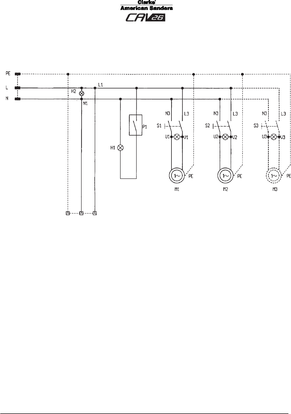
Electrical Schematic 6/06
(Optional)
(Optional)

Page -19-
Clarke® American Sanders Operator's Manual - CAV 26
CLARKE PRODUCT SUPPORT BRANCHES
PRODUCTION FACILITIES
ALTO Danmark A/S, Aalborg
Blytaekkervej 2
DK-9000 Aalborg
+45 72 18 21 00
ALTO Danmark A/S, Hadsund
Industrikvarteret
DK-9560 Hadsund
+45 72 18 21 00
SALES SUBSIDIARIES
ALTO US - Canada, Ontario (Canada)
4080 B Sladeview Crescent Unit 1
Mississauga, Ontario L5L 5Y5
(905) 569 0266
ALTO Overseas Inc., Sydney (Australia)
1B/8 Resolution Drive
Caringbah NSW 2229
+61 2 9524 6122
ALTO Cleaning Systems Asia Pte Ltd., Singapore
No. 17 Link Road
Singapore 619034
+65 268 1006
ALTO Deutschland GmbH, Bellenberg (Germany)
Guido-Oberdorfer-Straße 2-8
89287 Bellenberg
+49 0180 5 37 37 37
ALTO Cleaning Systems (UK) Ltd., Penrith
Gilwilly Industrial Estate
Penrith
Cumbria CA11 9BN
+44 1768 868 995
ALTO France S.A. Strasbourg
B.P. 44, 4 Place d’Ostwald
F-67036 Strasbourg
Cedex 2
+33 3 8828 8400
ALTO Nederland B.V.
Postbus 65
3370 AB Hardinxveld-Giessendam
The Netherlands
+31 184 677 200
ALTO Sverige AB, Molndal (Sweden)
Aminogatan 18
Box 4029
S-431 04 Molndal
+46 31 706 73 00
ALTO Norge A/S, Oslo (Norway)
Bjornerudveien 24
N-1266
+47 2275 1770
U. S. A. Locations European Locations
CORPO
PRODUCTION FACILITIES
Clarke® , Springdale, Arkansas
2100 Highway 265
Springdale, Arkansas 72764
(479) 750-1000
Customer Service - 1-800-253-0367
Technical Service - 1-800-356-7274
American Lincoln®, Bowling Green, Ohio 43402
1100 Haskins Road
SERVICE FACILITIES
Clarke®, Elk Grove, Illinois 60007
2280 Elmhurst Road
(847) 956-7900
Clarke®, Denver, Colorado 80204
1955 West 13th Ave.
(303) 623-4367
Clarke®, Houston, Texas 77040
7215 North Gessner Road
713-937-7717
SERVICE AND SALES FACILITY
American Lincoln® / Clarke, Madison Heights,
Michigan 48071-0158
29815 John R.
(810) 544-6300
American Lincoln® / Clarke, Marietta, Georgia 30066
1455 Canton Road
(770) 973-5225
Clarke®
Clarke American Sanders
A.L. Cook
Customer Service Headquarters and Factory
2100 Highway 265
Springdale, Arkansas 72764
(479) 750-1000
Technical Service
1-800-356-7274

Page -20- Clarke® American Sanders Operator's Manual - CAV 26
Clarke® American Sanders U. S. Warranty
This Clarke American Sanders Industrial/Commercial Product is warranted to be free from defects in
materials and workmanship under normal use and service for a period of two years from the date of pur-
chase, when operated and maintained in accordance with Clarke American Sanders's Maintenance and
Operations instructions.
This warranty is extended only to the original purchaser for use of the product. It does not cover normal
wear parts such as electrical cable, rubber parts, hoses and motor brushes.
If difficulty develops with the product, you should:
(a). Contact the nearest authorized Clarke American Sanders repair location or contact the Clarke American
Sanders Service Operations Department, 2100 Highway 265, springdale, Arkansas, for the nearest autho-
rized Clarke American Sanders repair location. Only these locations are authorized to make repairs to the
product under this warranty.
(b). Return the product to the nearest Clarke American Sanders repair location. Transportation charges to
and from the repair location must be prepaid by the purchaser.
(c). Clarke American Sanders will repair the product and or replace any defective parts without charge within
a reasonable time after receipt of the product.
Clarke American Sanders's liability under this warranty is limited to repair of the product and/or replace-
ment of parts and is given to purchaser in lieu of all other remedies, including INCIDENTAL AND CONSE-
QUENTIAL DAMAGES.
THERE ARE NO EXPRESS WARRANTIES OTHER THAN THOSE SPECIFIED HEREIN. THERE ARE NO
WARRANTIES WHICH EXTEND BEYOND THE DESCRIPTION OF THE FACE HEREOF. NO WARRANTIES,
INCLUDING BUT NOT LIMITED TO WARRANTY OF MERCHANTABILITY, SHALL BE IMPLIED. A warranty
registration card is provided with your Clarke American Sanders product. Return the card to assist Clarke
American Sanders in providing the performance you expect from your new floor machine.
Clarke, 2100 Highway 265, Springdale, Arkansas 72764.
Clarke American Sanders reserves the right to make
changes or improvements to its machine without notice.
Always use genuine Clarke American Sanders Parts for repair.
2100 Highway 265
Springdale, Arkansas, 72764
