ClearCount Medical Solutions CCMS001 Automatic RFID Sponge Counting System User Manual
ClearCount Medical Solutions Inc. Automatic RFID Sponge Counting System
UserManual.wiki
>
ClearCount Medical Solutions
>
CCMS001 User Manual
User Manual
Navigation menu
Upload a User Manual
Namespaces
Wiki Guide
HTML
PDF
Info
Views
User Manual
Discussion / Help
Navigation
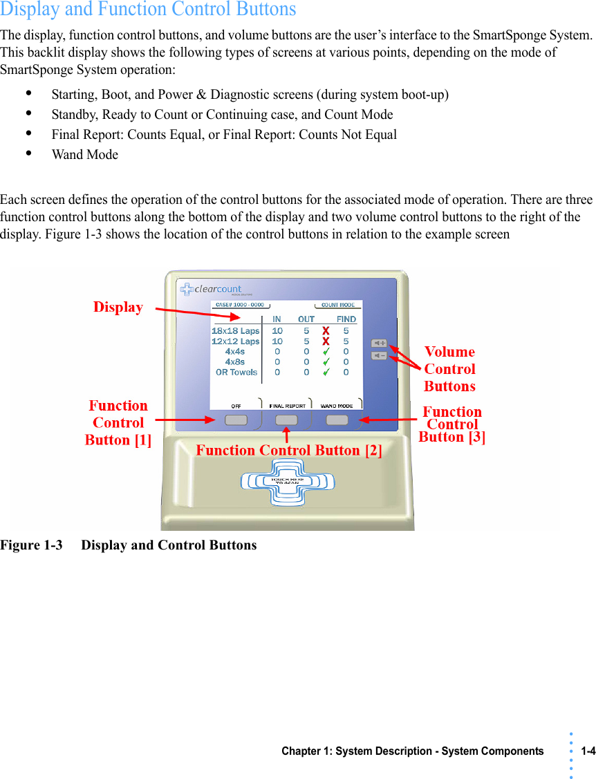
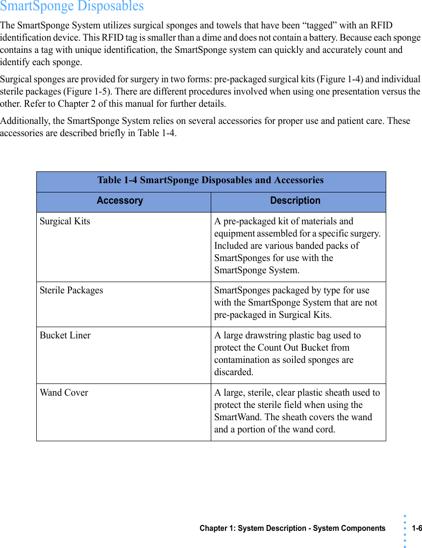
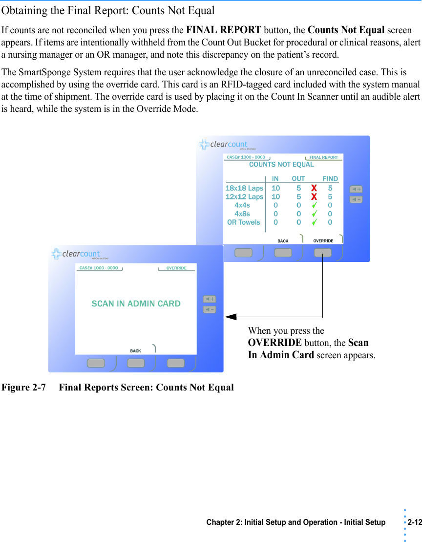
![1-5 Chapter 1: System Description - System Components• • • •••Table 1-3 Display/ControlsDisplay / Controls DescriptionDisplay LCD that provides information to the user regarding operation of the system.Volume Control Buttons These up and down buttons control the volume of the audible alert. The Volume of the alert can be set to four different levels and off with each button.Function Control Button [1] Allows the following actions; On - Turns the system on from Standby Mode. Off - Returns the system to Standby Mode.Function Control Button [2] Allows; Final Count - Exits Count Mode and proceeds to a final count screen for verification before ending a case. Back - Lets the user exit the final count screen and return to Count Mode.Function Control Button [3] Allows; Wand Mode - Switches from Count Mode to Wand Mode. Count Mode - Switches Back from Wand Mode to Count Mode. OverRide - Allows the user an option to end a case without reconciling the sponge counts with an Admin Card. End Case - Ends case and returns to standby.](https://usermanual.wiki/ClearCount-Medical-Solutions/CCMS001/User-Guide-1062509-Page-9.png)