ClearOne COM Interact COM-W User Manual PDF Output
ClearOne, Inc. Interact COM-W PDF Output
UserManual.wiki
>
ClearOne
>
COM User Manual
Exhibit 8
Navigation menu
Upload a User Manual
Namespaces
Wiki Guide
HTML
PDF
Info
Views
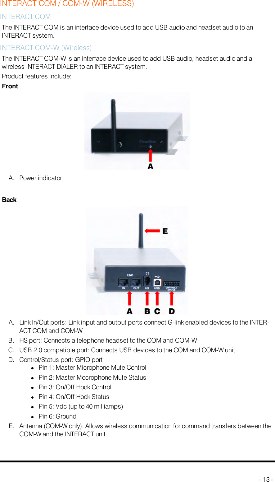
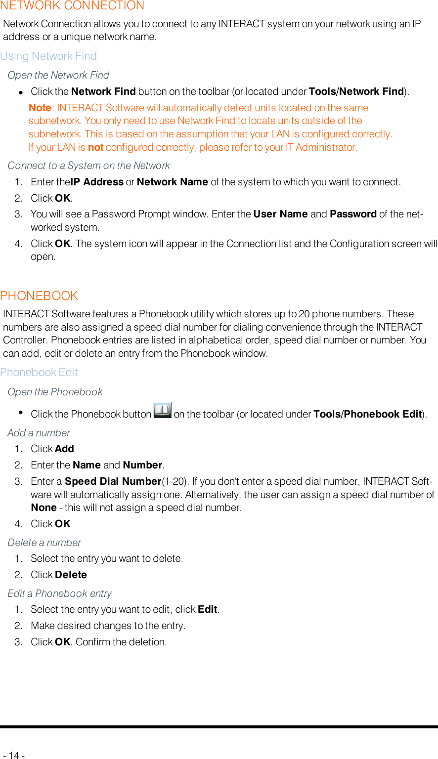
User Manual
Discussion / Help
Navigation