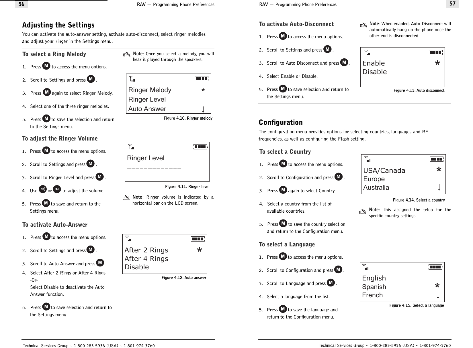
ClearOne RAV1 ClearOne Communications RAV 600/900 Controller User Manual RAV 69 chap 1
ClearOne, Inc. ClearOne Communications RAV 600/900 Controller RAV 69 chap 1
UserManual.wiki
>
ClearOne
>
RAV1 User Manual
Exhibit 8
Navigation menu
Upload a User Manual
Namespaces
Wiki Guide
HTML
PDF
Info
Views
User Manual
Discussion / Help
Navigation

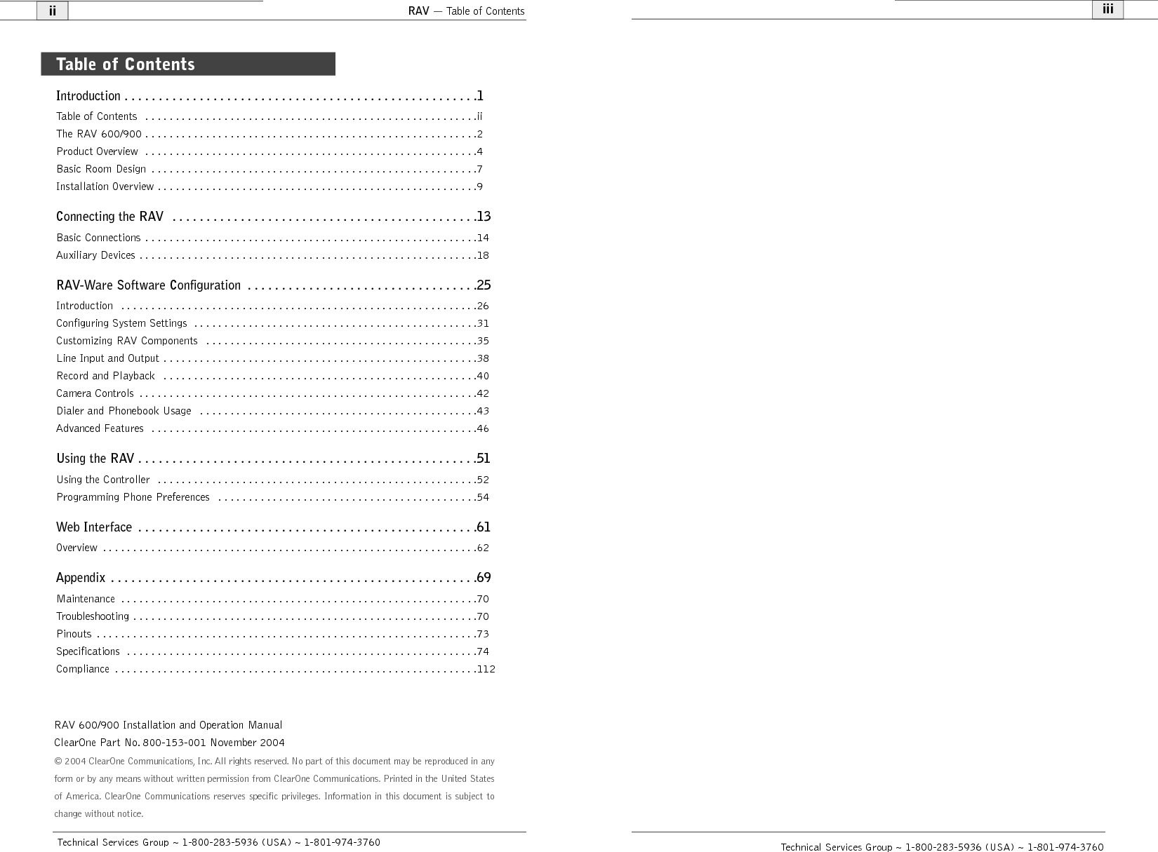
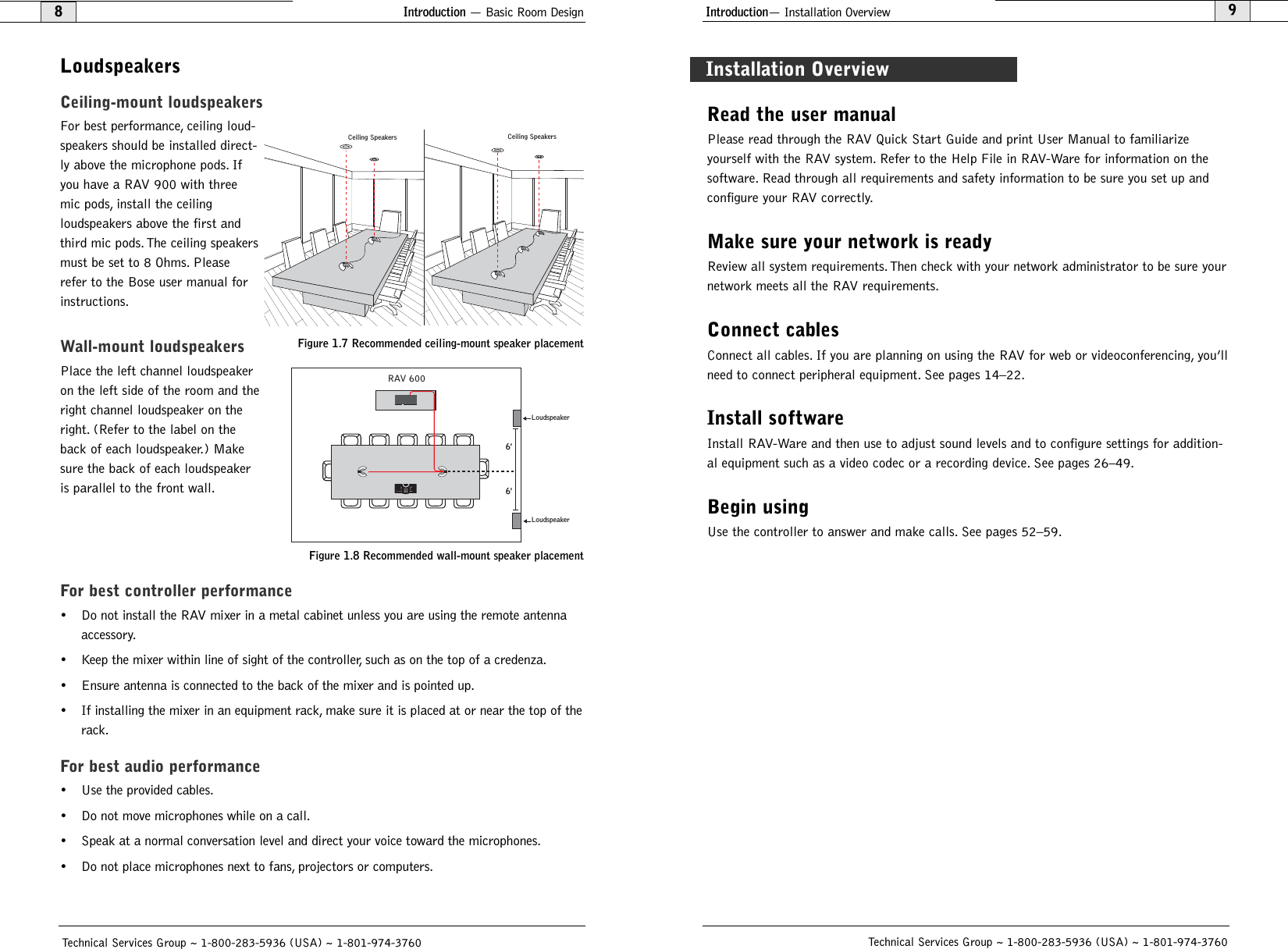
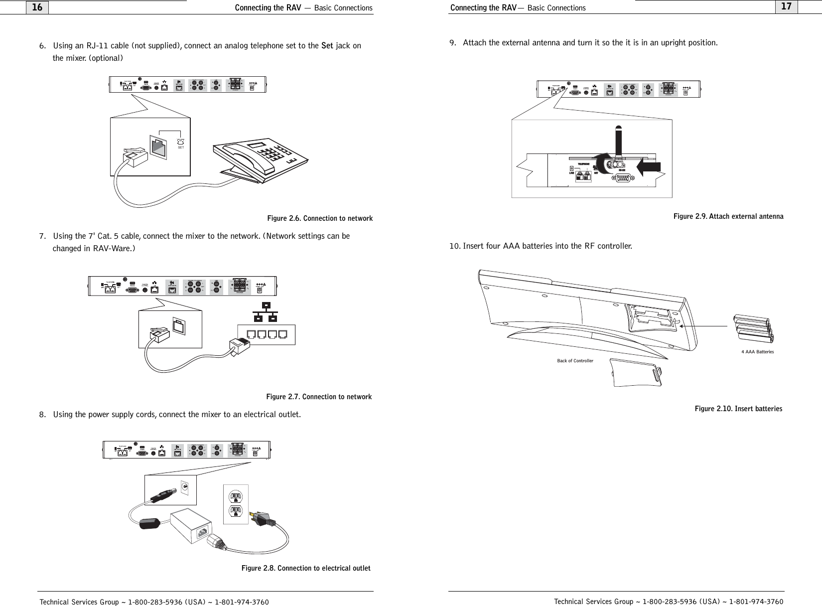
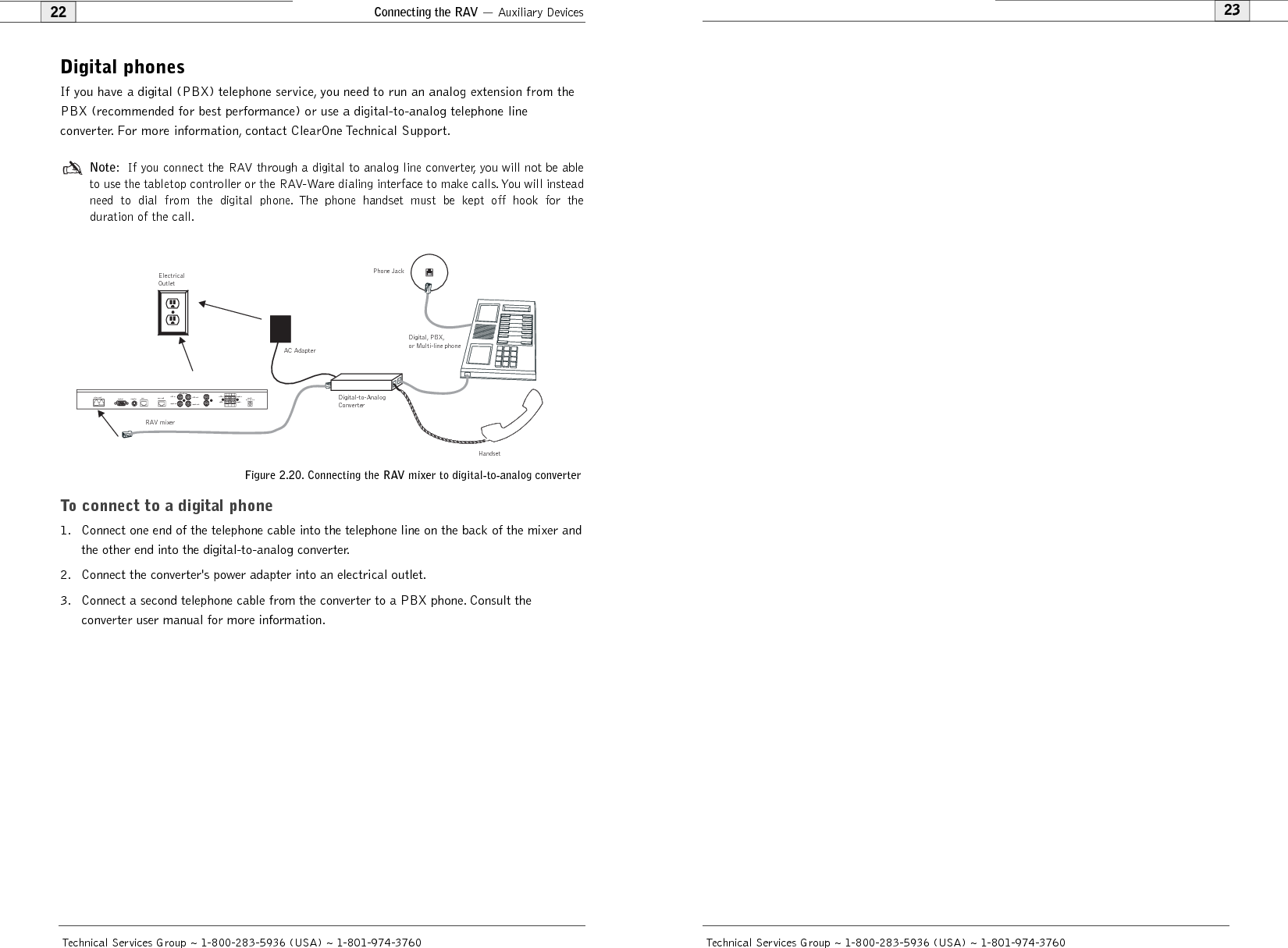
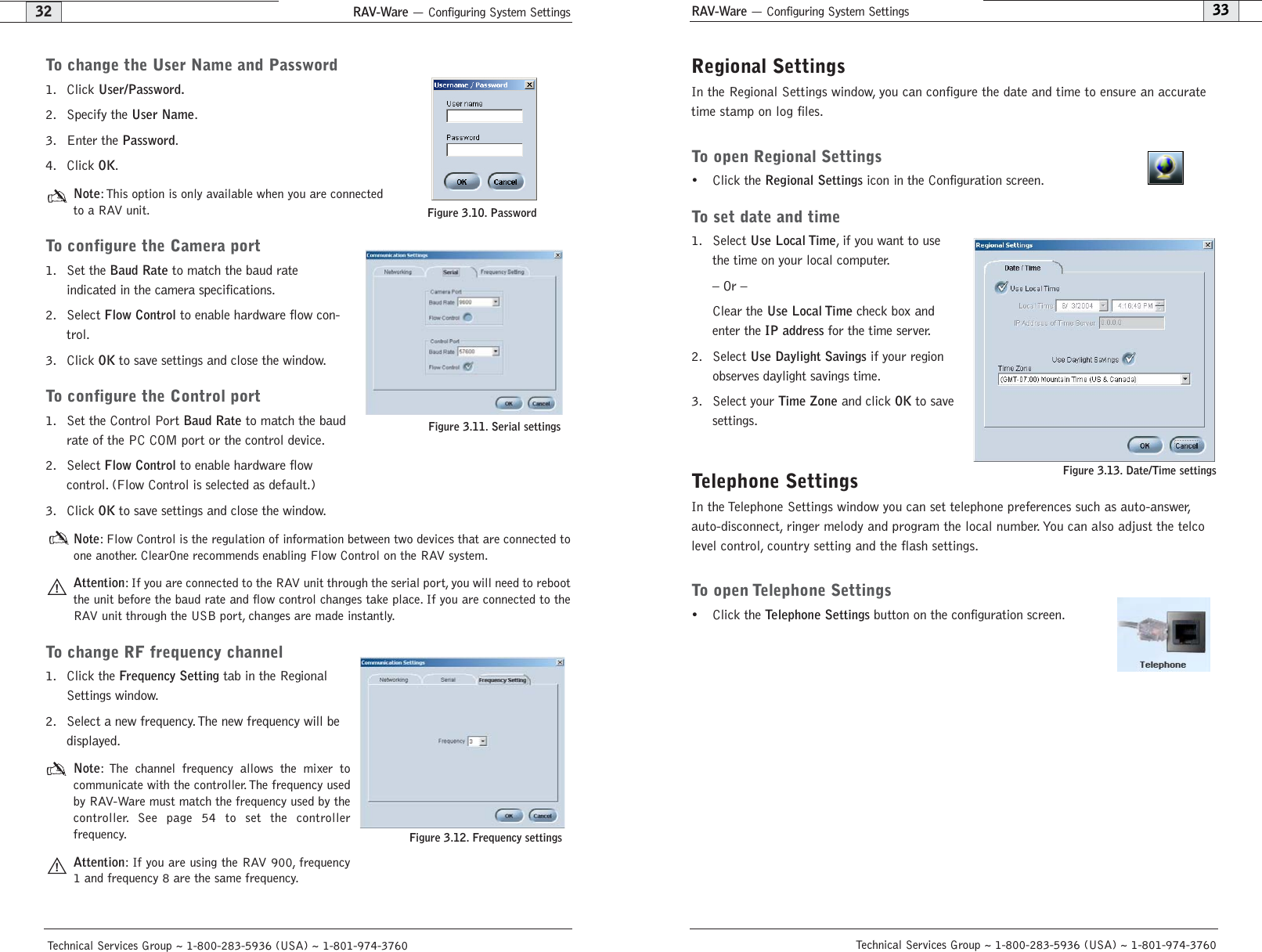
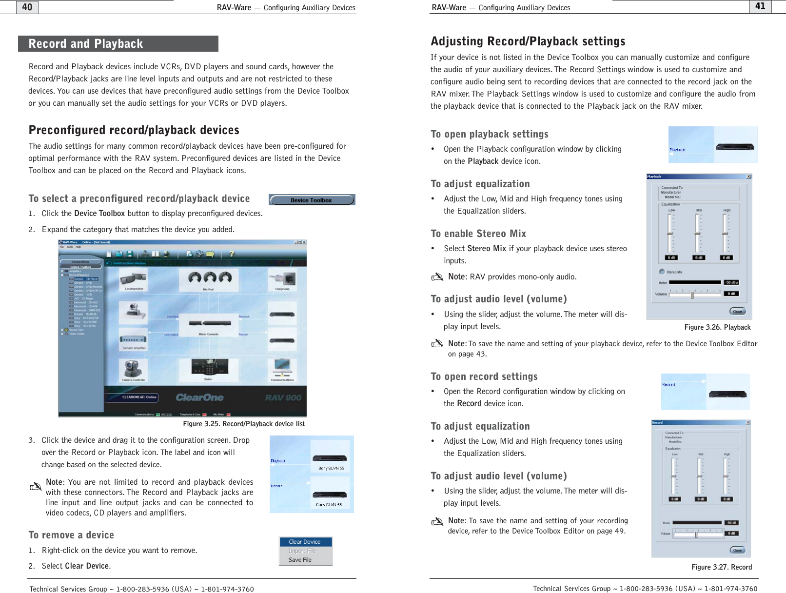
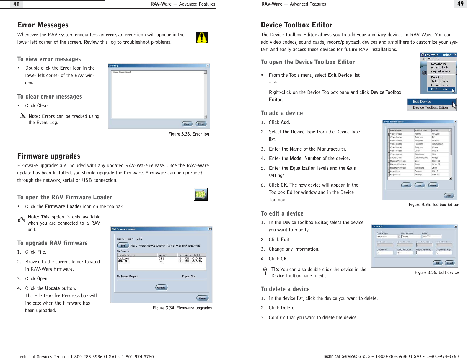
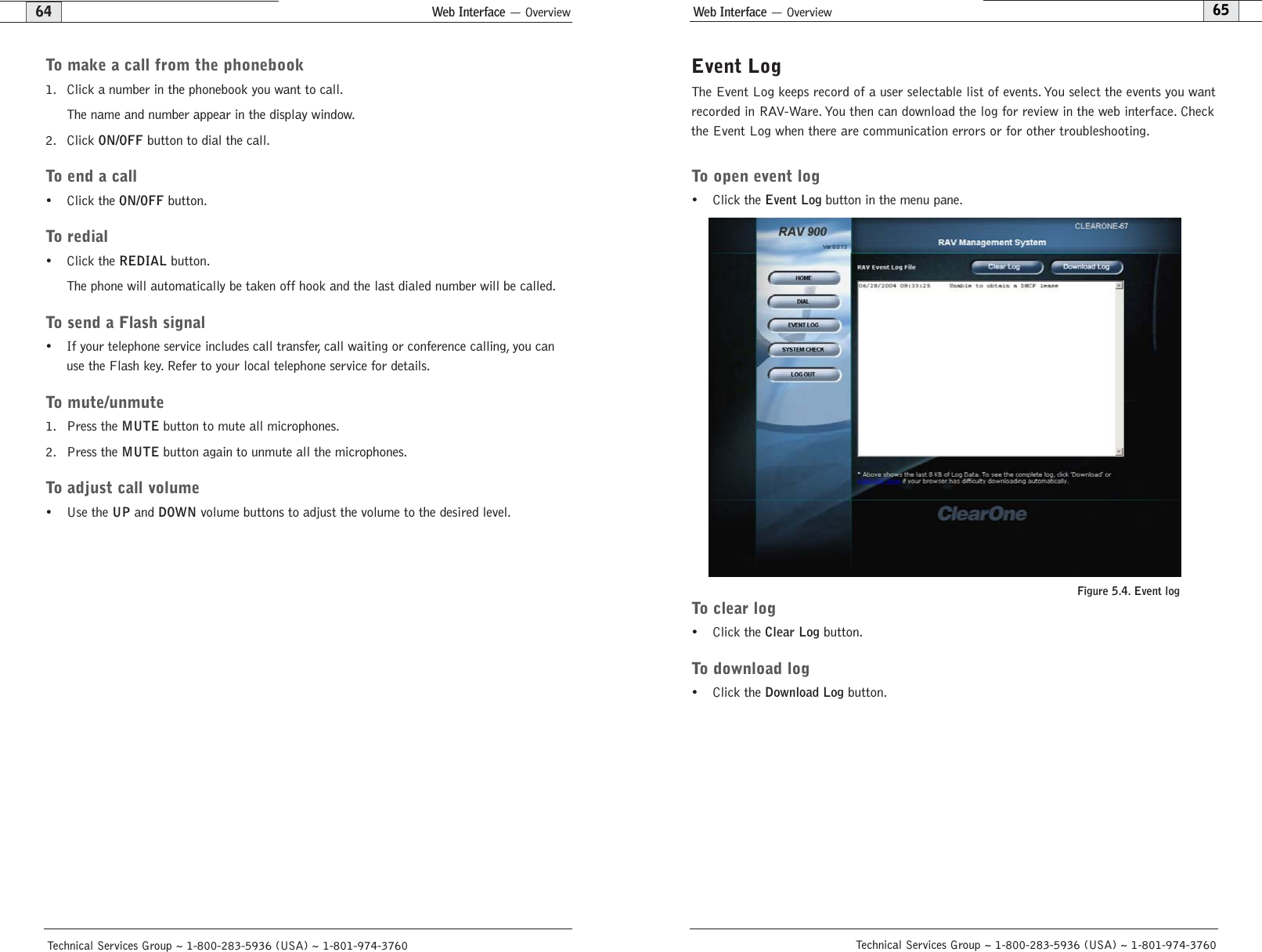

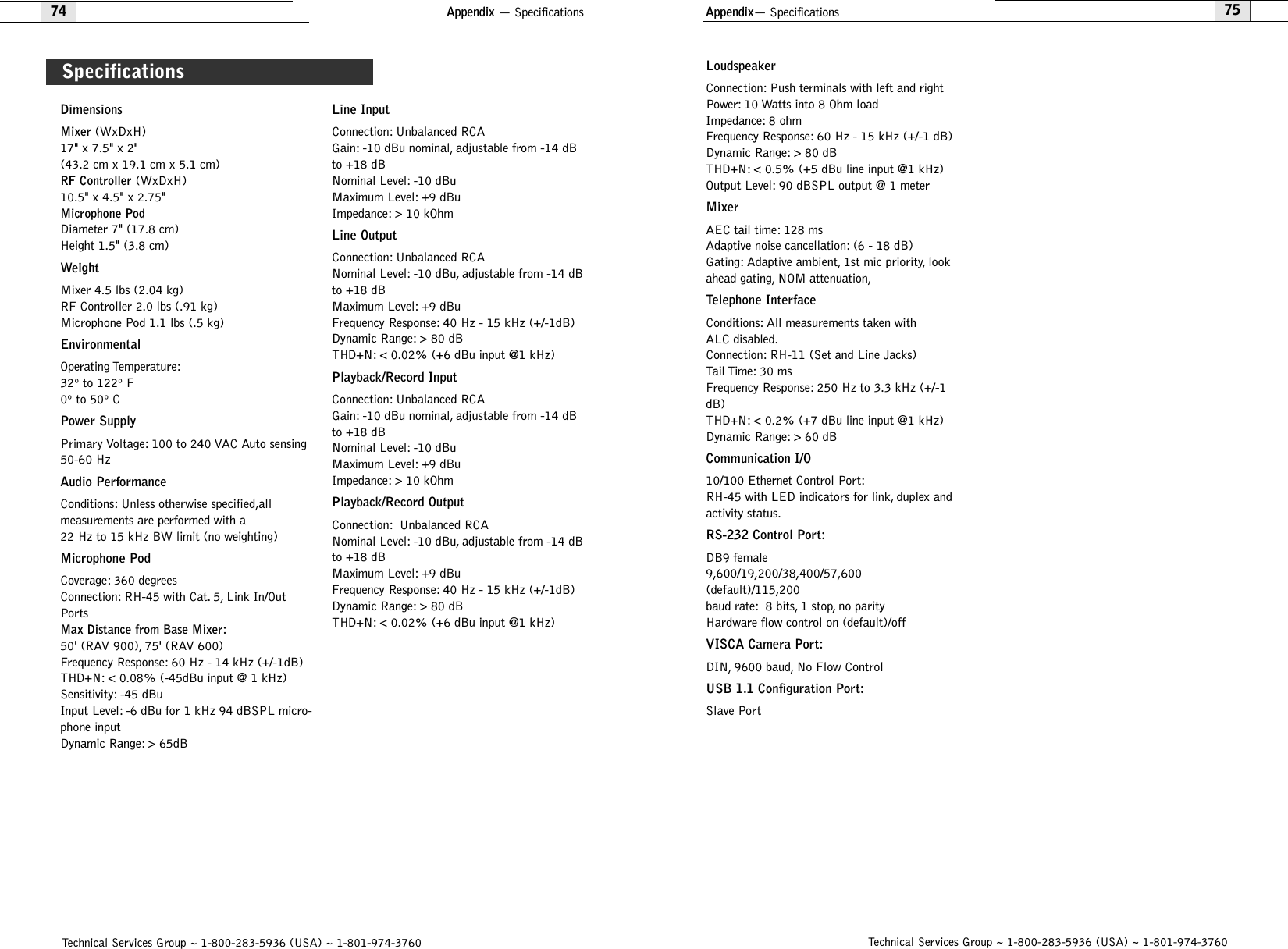
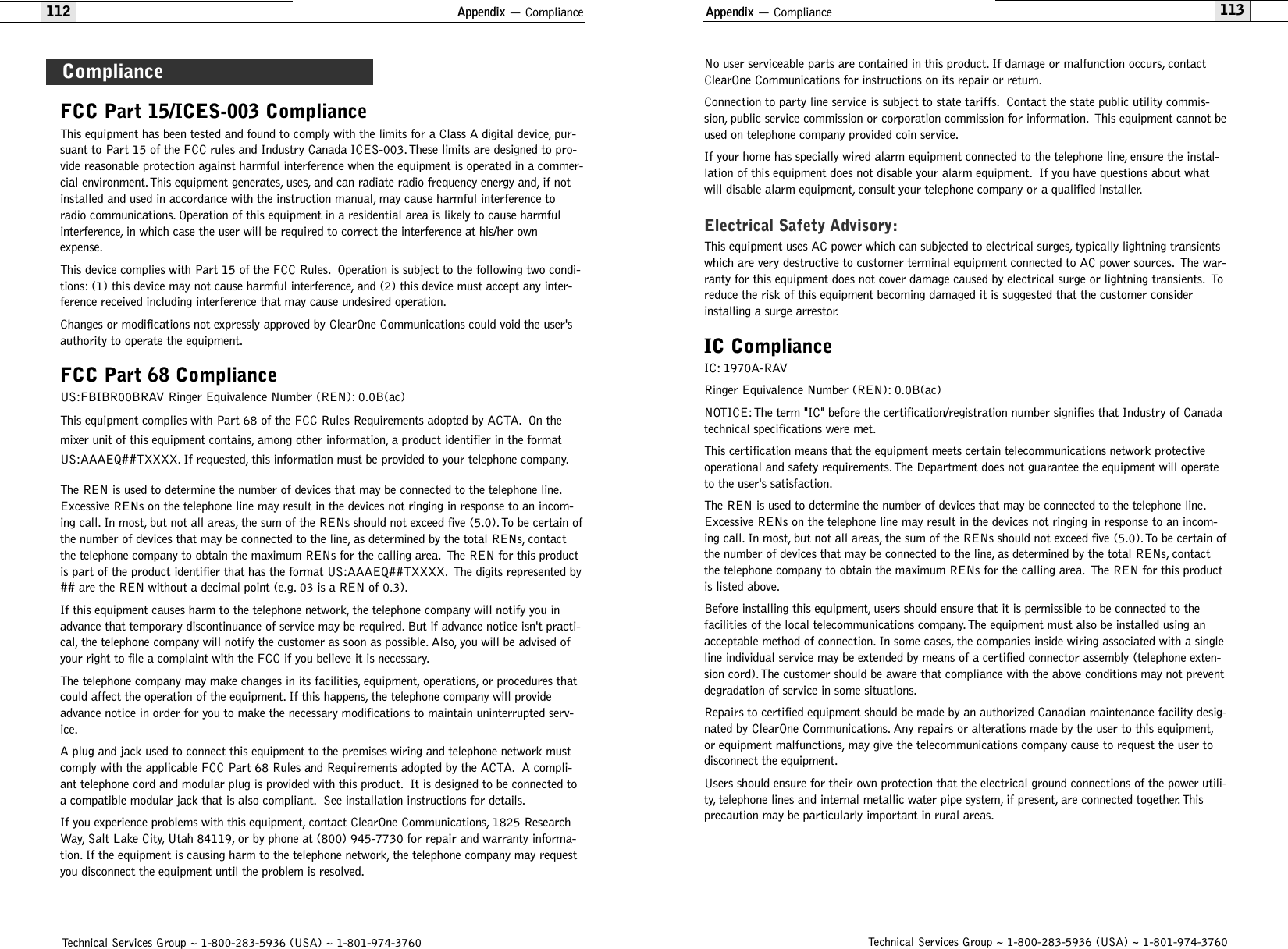
![Appendix— Serial Commands77Appendix— Serial Commands76Technical Services Group ~ 1-800-283-5936 (USA) ~ 1-801-974-3760 Technical Services Group ~ 1-800-283-5936 (USA) ~ 1-801-974-3760The RAV 600 and RAV 900 accept serial commands through the telnet, RS-232 serial portor USB. The commands in this manual pertain only to the RAV 600 and RAV 900. RS-232serial port protocol is 9,600, 19,200, 38,400 , 57,600 (default) or 115,200 baud; 8 bits, 1stop bit, no parity.ConventionsThe following typographic conventions are used in this document to describe the differentserial commands. Use the Command structure section and the examples as a guide whencreating your serial commands.Convention Description<X> Parameters enclosed in < > indicate a mandatory parameter.[X] Parameters enclosed in [ ] indicate an optional parameter.1-8 Parameters separated by a - indicate a range between the values.4,7,9 Parameters separated by a , indicate a list of available values.BAUD Words in uppercase bold indicate command text.DEVICEIndicates the device type and device id.Command structureCommands can be either UPPER CASE or lower case. Also, extra spaces or tabs betweenarguments in text commands are allowed. Return values are always in upper case. In orderfor a command to be recognized by the serial port, the command must be terminated by acarriage return.The structure of serial commands is as follows: #TYPE DEVICE COMMAND [X] [X]# indicates the start of a command lineDEVICE represents the device type and device numberCOMMAND is the command text[X] [X] represents any additional options in the order that they appear in the command descriptions that follow* placed in the Type ID or Device ID fields, the command applies to all units or all devices respectively.ExampleA command to disable automatic gain control for Mic 2 on a RAV 600 device “0” will havethe command line: #50 AGC 2 M 0. In this command line, 5=RAV 600, 0=unit 0,AGC=command, 2=channel, M=Mic Input group, 0=off state. If a command calls for a“null” value, leave a blank in the command line. For example, “#50 AGC 2 M” will returnthe current AGC state of Mic 2 on device 50.Command responses will have a carriage return line feed.Example: #50 AGC 2 M O carriage return line feedGroups and channelsThe following tables define the relationship between alpha and numeric representations. Textcommands use the alpha designation and binary commands use the numeric. In addition,different groups have different allowable channel ranges.Type and device IDsType ID Unit type Device ID range0x8 RAV 900 0x00x9 RAV 600 0x0Group Alpha Number RAV 900Channel RangeRAV 600Channel RangeUnknown 0 N/A N/AOutputs O 2 1 – 31 is Record Out2 is Aux Out3 is Speaker Out1 – 31 is Record Out2 is Aux Out3 is Speaker OutMicrophone Pod M 3 1 – 3 1 – 3 Line Inputs L 7 1 – 21 is Record In2 is Aux In1 – 21 is Record In2 is Aux InUnitMatrixTransmitLocal CameraU 9 0 for Unit Values1 for Log0X11 0 0S 13 Phonebook 0N 15 2 for HTML skin3 for Firmware4 for Directory5 for Firmware Data1ReceiveT16 1 1R17 1 1V19Sony Mode: 1–7Canon Mode: 1–9Sony Mode: 1–7Canon Mode: 1–9Serial Commands](https://usermanual.wiki/ClearOne/RAV1/User-Guide-490705-Page-41.png)
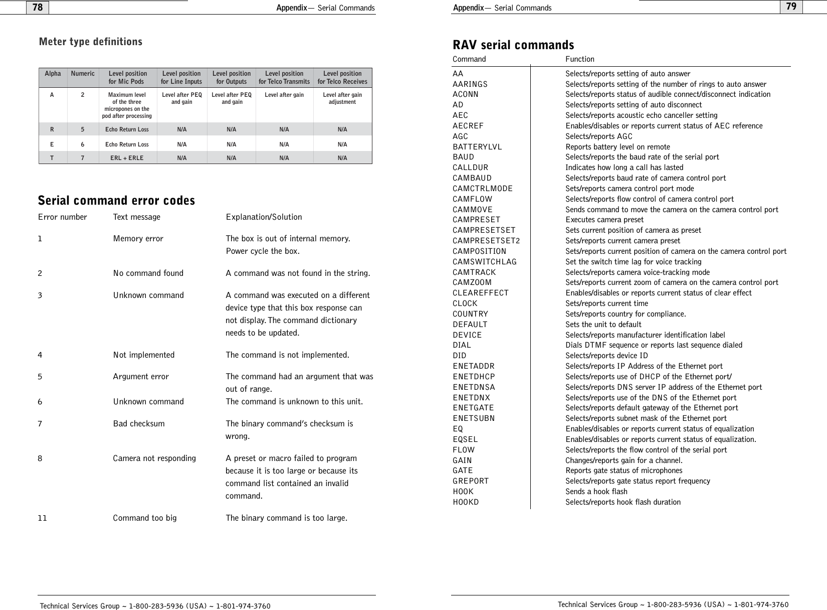
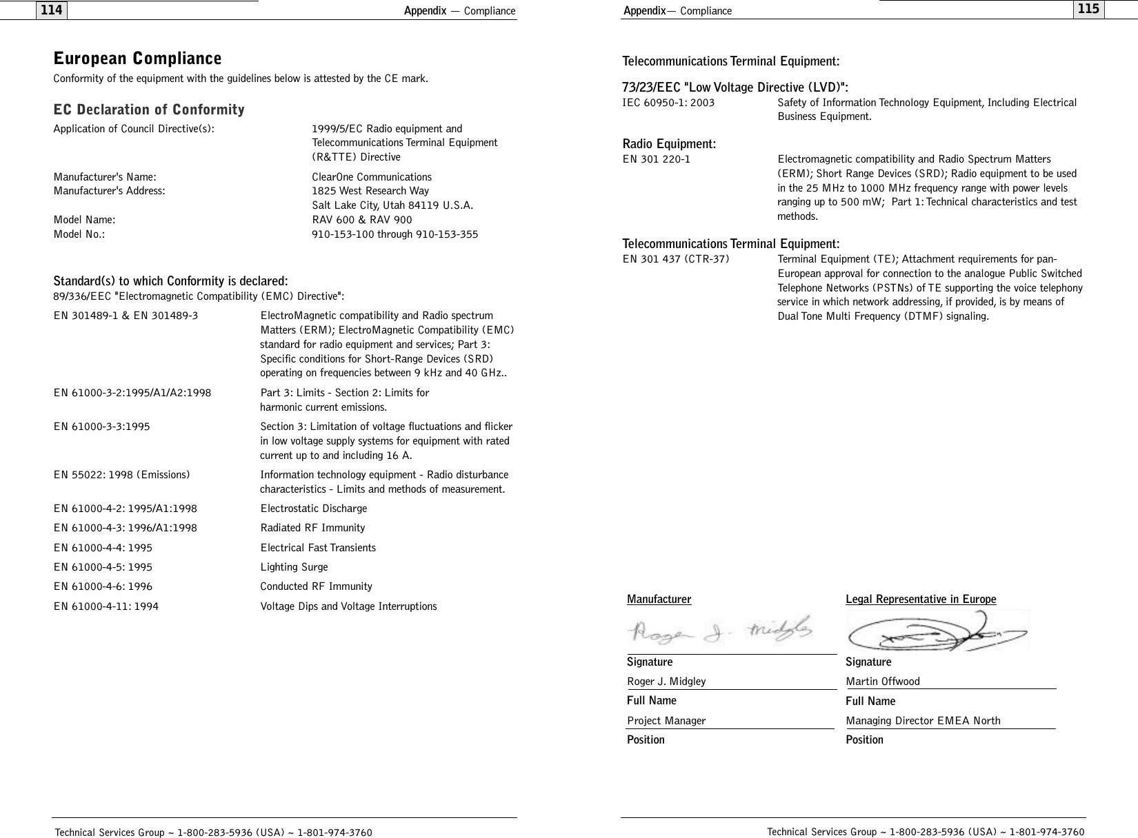
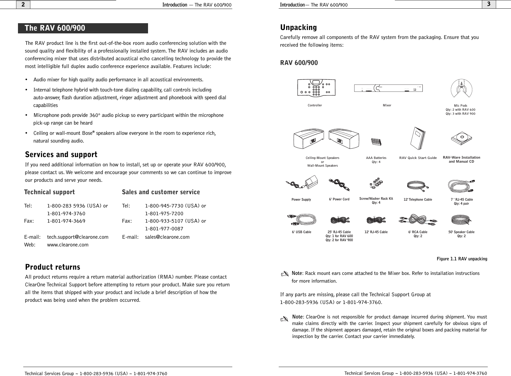
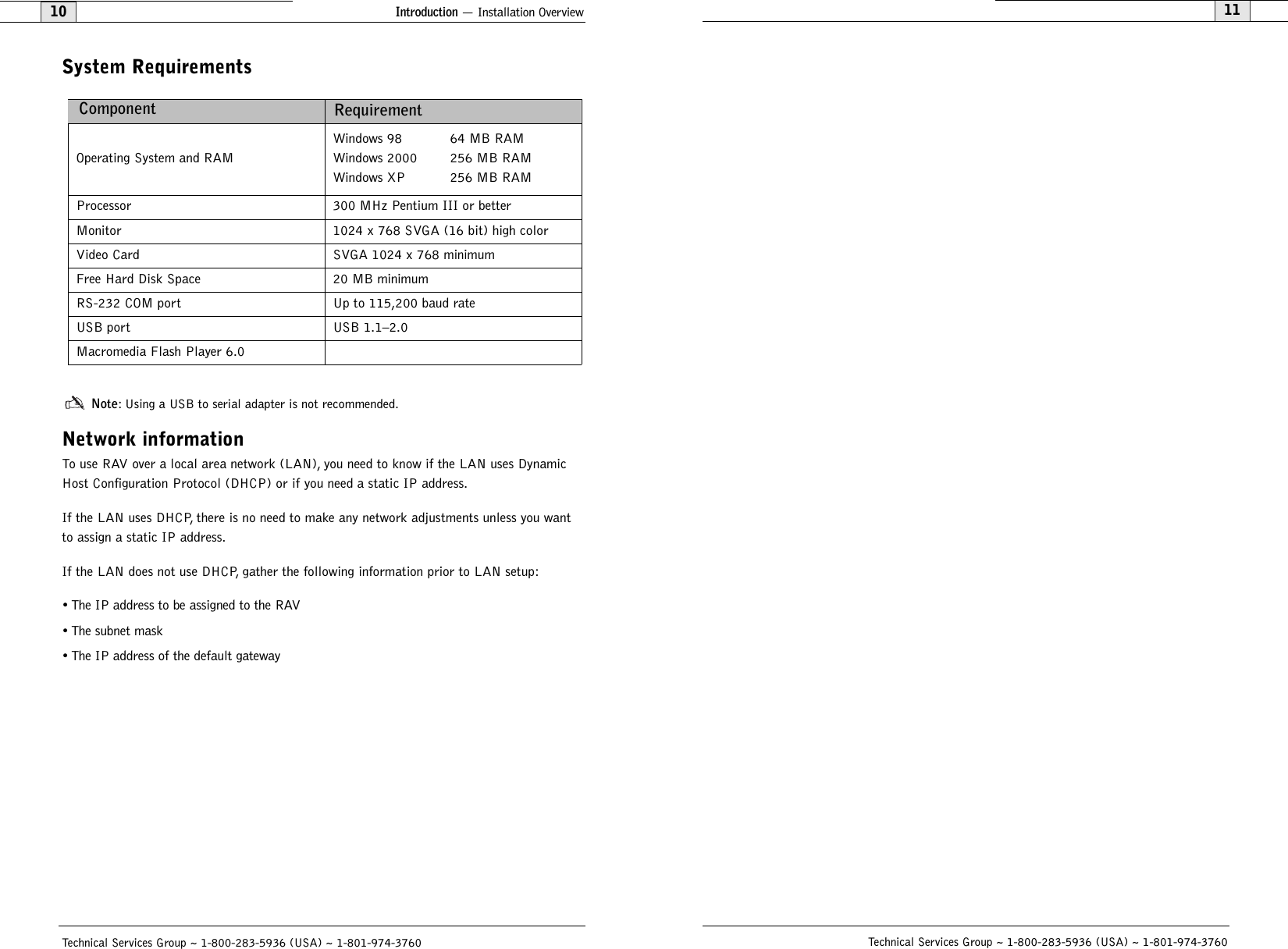
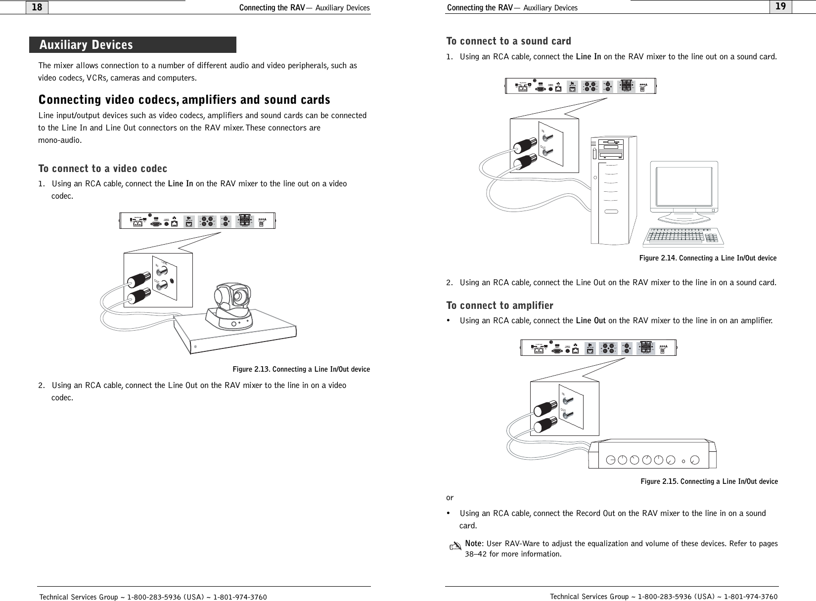
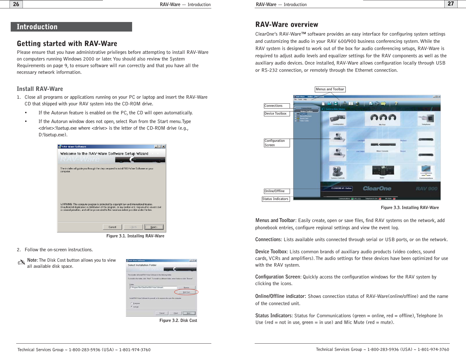
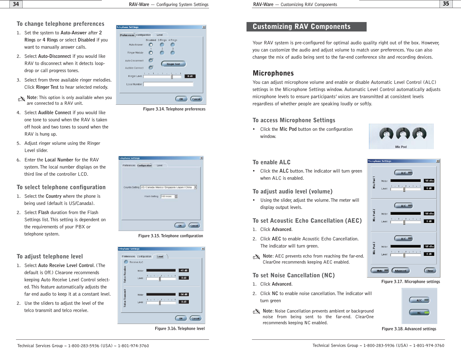
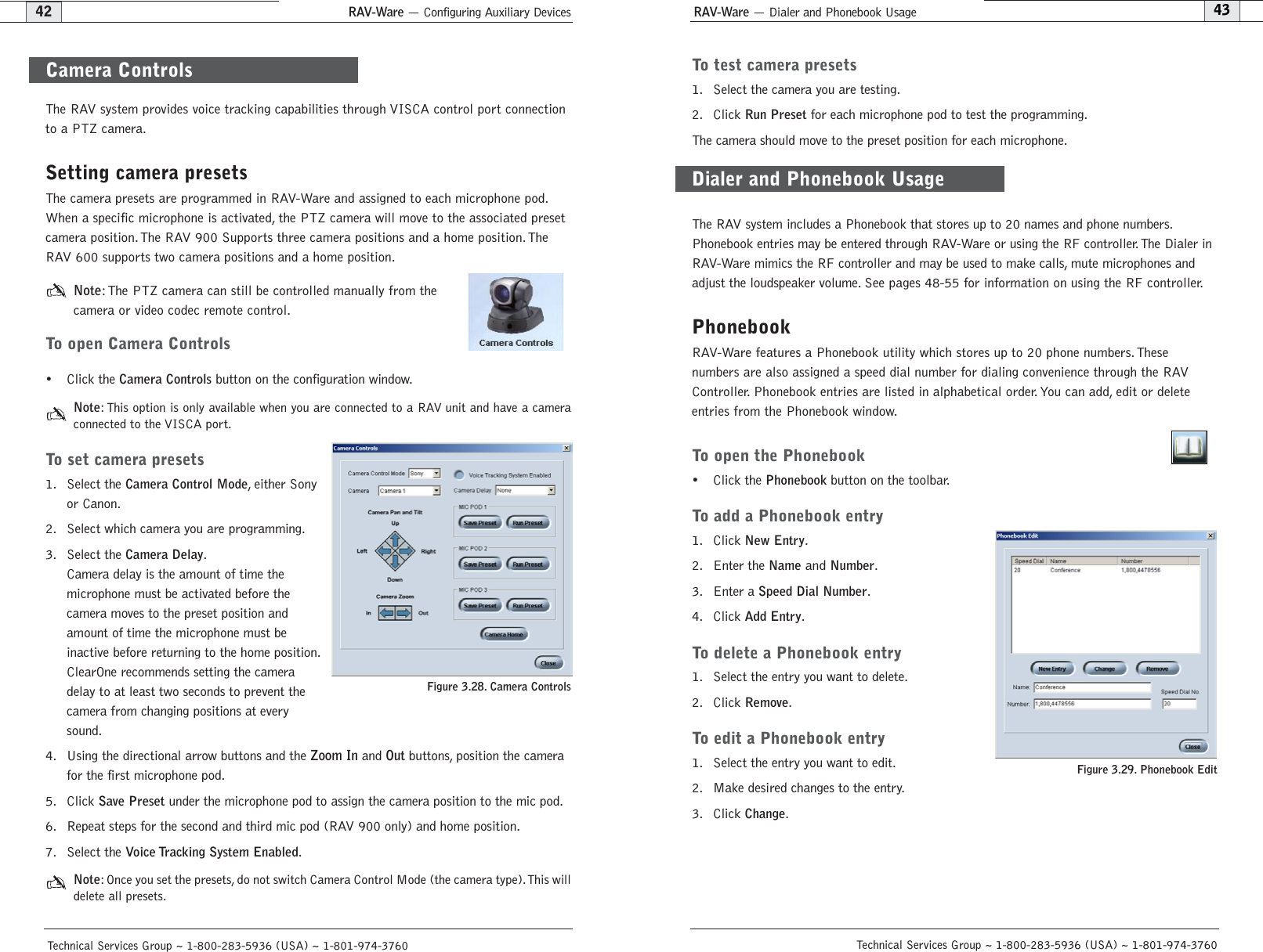
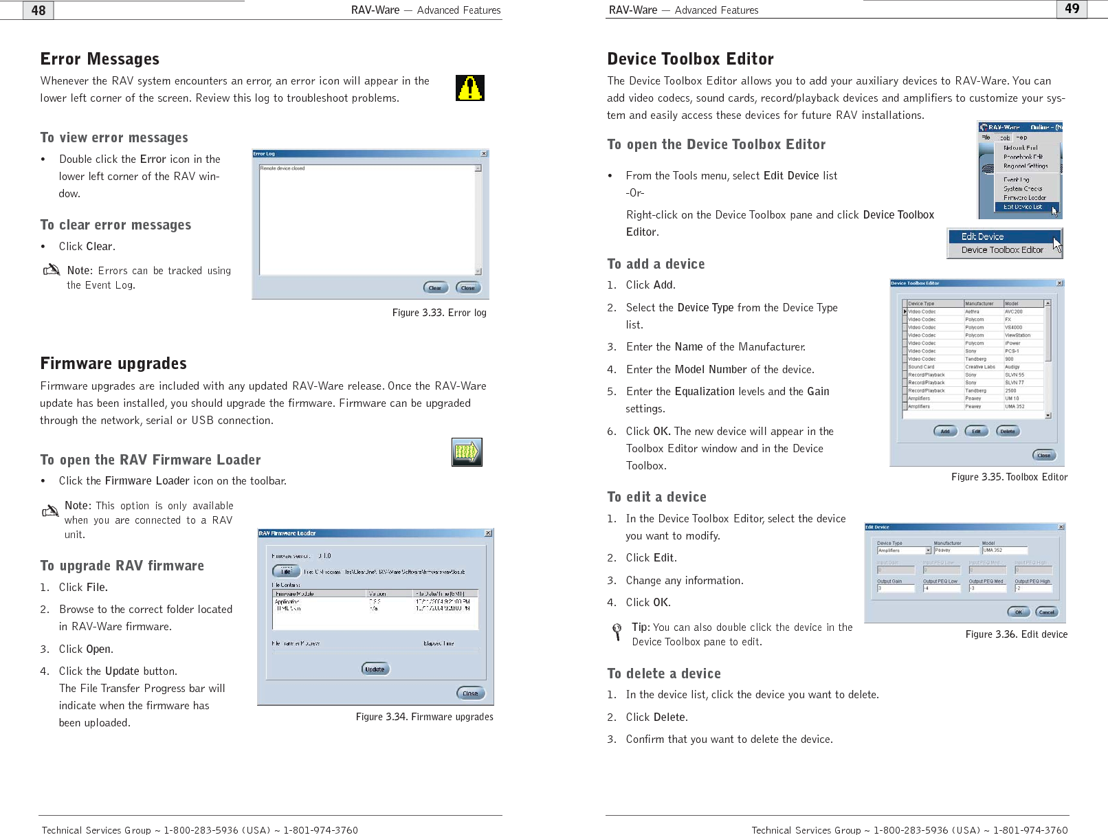
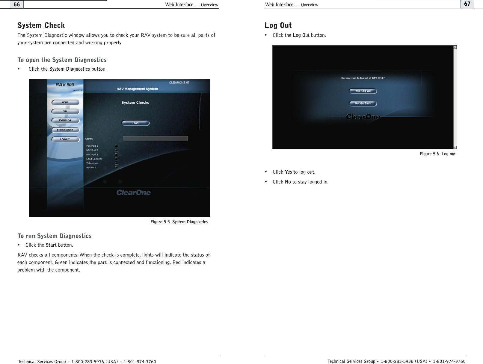
![Appendix— Serial Commands81AA - Auto Answer Enable/ DisableThis command selects/reports the setting of auto answer.ARGUMENT DETAILSName Type Size Values UnitsChannel Channel 1 See Group And ChannelsGroup Group 1 17 (R)Value Unsigned Integer 2 0 = Off1 = On2 = Toggle(Null to query in text)BINARY FORM DETAILSCOMMAND ID:28NUMBER OF ARGUMENTS:1ARGUMENT FORM: <Channel><Group><Value>TEXT FORM DETAILSCOMMAND FORM: DEVICE AA <Channel> [Value] AARINGS - Number of Rings to Auto Answer OnThis command selects/reports the setting of the number of rings to auto answer.ARGUMENT DETAILSName Type Size Values UnitsChannel Channel 1 See Group And ChannelsGroup Group 1 17 (R)Value Unsigned Integer 2 2 or 4(Null to query in text)BINARY FORM DETAILSCOMMAND ID: 31NUMBER OF ARGUMENTS: 1ARGUMENT FORM: <Channel><Group><Value>TEXT FORM DETAILSCOMMAND FORM: DEVICE AARINGS <Channel> [Value] Technical Services Group ~ 1-800-283-5936 (USA) ~ 1-801-974-3760Appendix — Serial Commands80Technical Services Group ~ 1-800-283-5936 (USA) ~ 1-801-974-3760Command FunctionLABEL Selects/reports label of specified channel or unitLOCALNUM Sets/reports current value of local numberLVL Reports in, out, or processor levelLVLREPORT Selects/reports level statusLVLREPORTEN Enables/Disables level reportingMANUFACTURER Selects/reports manufacturer identification labelMICCAMPRESET Associate a microphone with a camera presetMTRX Selects/reports matrix routing of an in. to out.MUTE Sets/reports mute statusNCSEL Enables/Disables or reports current status of noise cancellationPBDIAL Dials speed dial number by namePHONEBOOKADD Saves entry in the phonebookPHONEBOOKCNT Queries number of entries in phonebookPHONEBOOKDEL Deletes an entry in the phonebookPHONEBOOKREAD Queries an entry in the phonebookREDIAL Redials last number calledRESET Resets the unitRFFREQ Sets/reports frequency for RF link to remote.RING Indicates a ringing line.RINGERLVL Selects/reports audible ring levelRINGERSEL Sends/reports audible ring melodyRINGERTEST Plays current audible ringer melodySILENCEPRST Associates camera preset with silence for voice trackingSPEEDDIAL Dials speed dial number by speed dial numberSTEREOMIX Enables/disables or reports stereo mix status SYSCHECKS Initiates system checksTE Selects/reports hook statusTELCOLVLCTRL Selects/reports setting of Telco TX level controlUID Reports unit ID (read only)VER Reports unit version (read only)VOLUME Changes/reports the gain for the output channel](https://usermanual.wiki/ClearOne/RAV1/User-Guide-490705-Page-43.png)
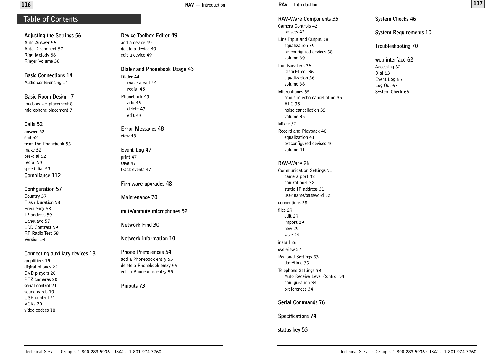
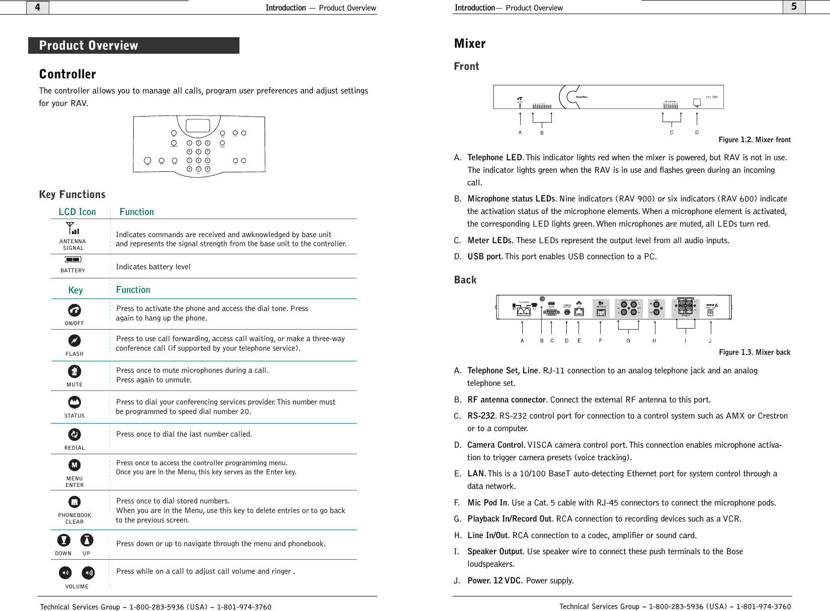
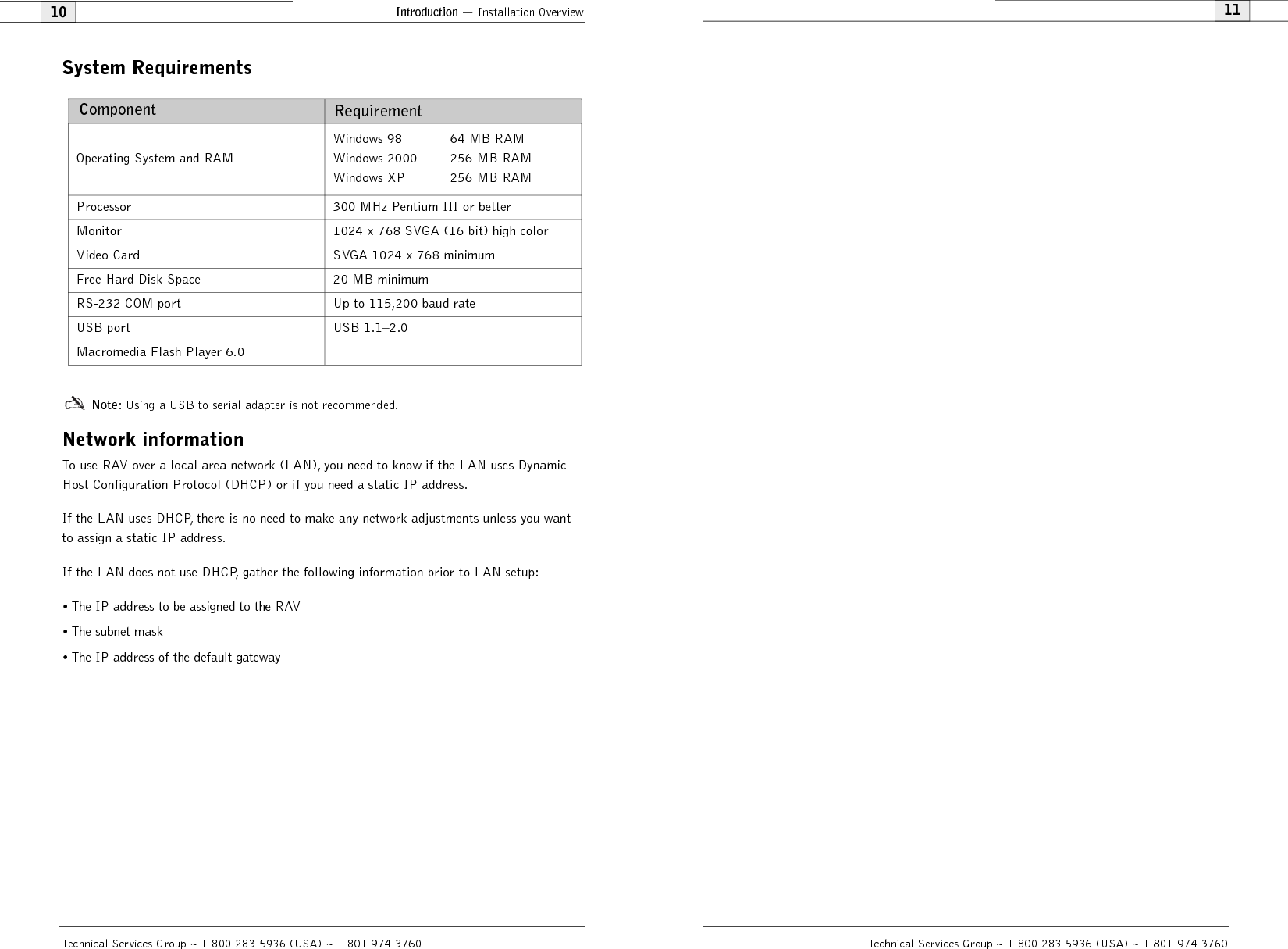
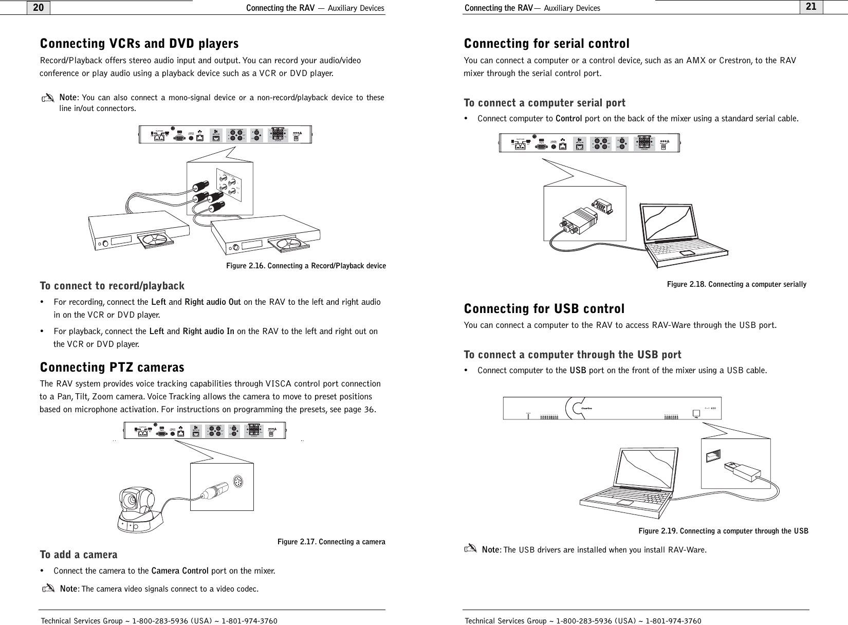
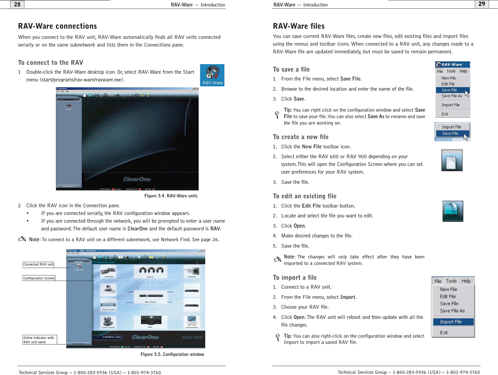
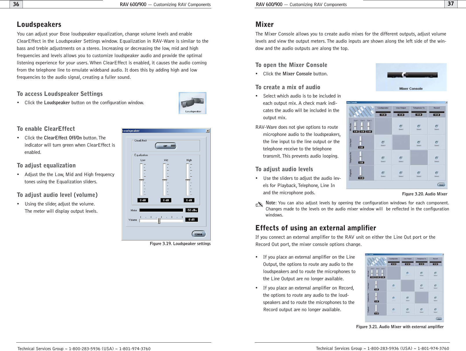
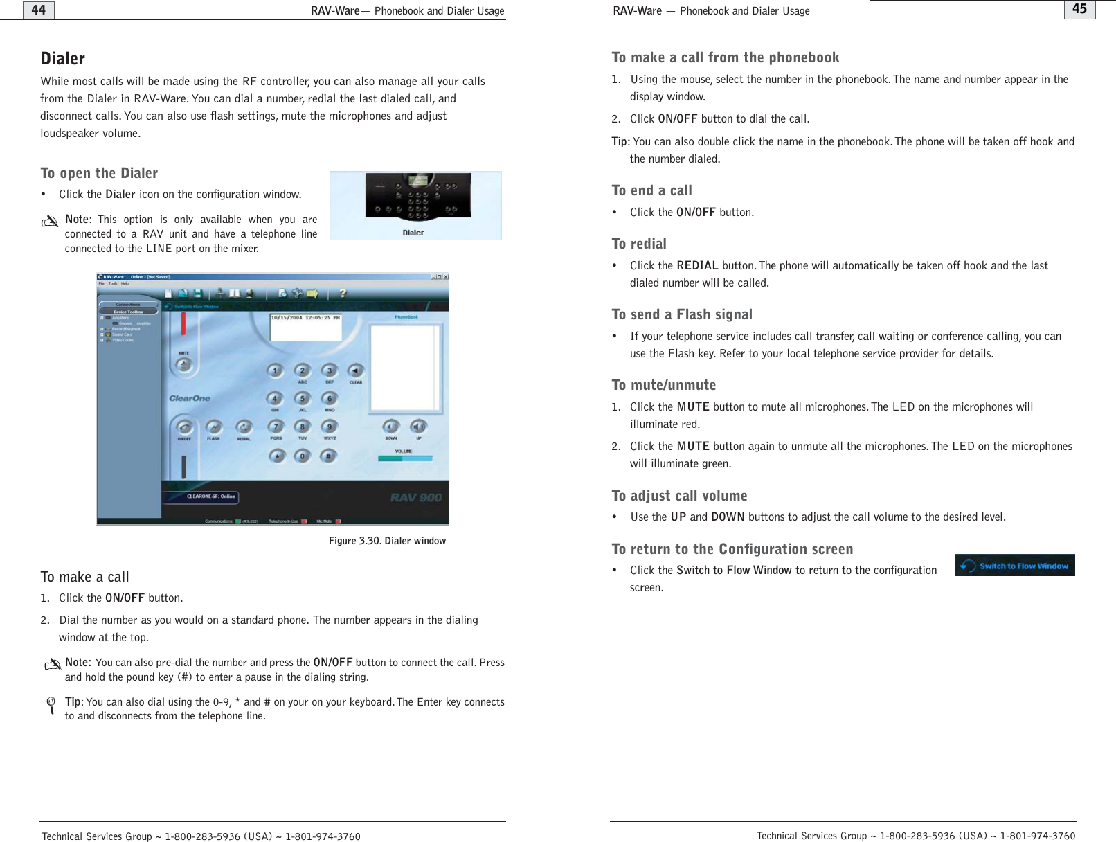
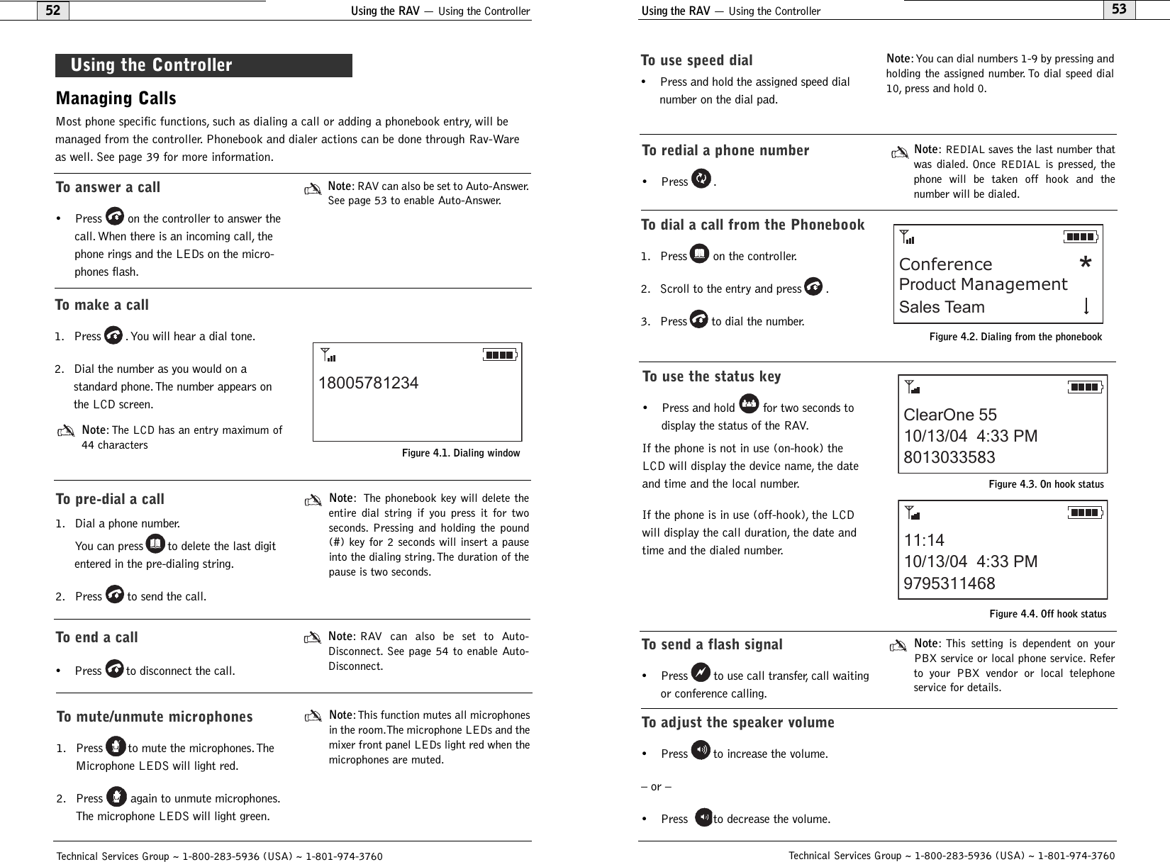
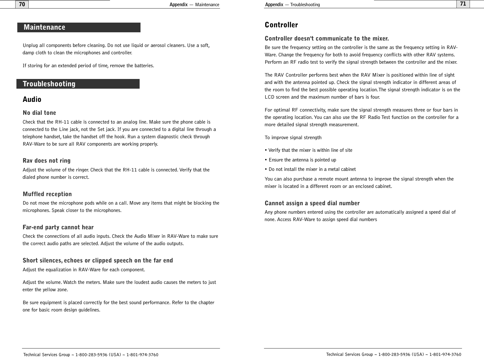
![Appendix— Serial Commands83AEC - Acoustic Echo Canceller enable/ disableThis command selects/reports the setting of Acoustic Echo Canceller.ARGUMENT DETAILSName Type Size Values UnitsChannel Channel 1 See Group And ChannelsGroup Group 1 3 (M)Value Unsigned Integer 2 0 = Off1 = On2 = Toggle(Null to query in text)BINARY FORM DETAILSCOMMAND ID:27NUMBER OF ARGUMENTS:1ARGUMENT FORM: <Channel><Group><Value>TEXT FORM DETAILSCOMMAND FORM: DEVICE AEC <Channel> [Value]AECREF - Acoustic Echo Cancellation ReferenceThis command enables/disables or reports the current status of the AEC reference.ARGUMENT DETAILSName Type Size Values UnitsValue Unsigned Integer 4 1 - 3(Null to query in text)BINARY FORM DETAILSCOMMAND ID:68NUMBER OF ARGUMENTS:1ARGUMENT FORM: <Value>TEXT FORM DETAILSCOMMAND FORM: DEVICE AECREF [Value] AGC - Automatic Gain ControlThis command selects/reports the setting of automatic gain control.ARGUMENT DETAILSName Type Size Values UnitsChannel Channel 1 See Group And ChannelsGroup Group 1 3 (M)Value Unsigned Integer 2 0 = Off1 = On2 = Toggle(Null to query in text)BINARY FORM DETAILSCOMMAND ID:1NUMBER OF ARGUMENTS:1ARGUMENT FORM: <Channel><Group><Value>TEXT FORM DETAILSCOMMAND FORM:DEVICEAGC <Channel> <Group> [Value] Technical Services Group ~ 1-800-283-5936 (USA) ~ 1-801-974-3760Appendix — Serial Commands82Technical Services Group ~ 1-800-283-5936 (USA) ~ 1-801-974-3760ACONN - Audible Connect / Disconnect IndicationThis command selects/reports the status of the audible connect/disconnect indication.ARGUMENT DETAILSName Type Size Values UnitsChannel Channel 1 See Group And ChannelsGroup Group 1 17 (R)Value Unsigned Integer 2 0 = Off1 = On2 = Toggle(Null to query in text)BINARY FORM DETAILSCOMMAND ID:96NUMBER OF ARGUMENTS:1ARGUMENT FORM: <Channel><Group><Value>TEXT FORM DETAILSCOMMAND FORM: DEVICE ACONN <Channel> [Value]AD - Auto Disconnect Enable/ DisableThis command selects/reports the setting of auto disconnect.ARGUMENT DETAILSName Type Size Values UnitsChannel Channel 1 See Group And ChannelsGroup Group 1 17 (R)Value Unsigned Integer 2 0 = Off1 = Loop Drop2 = Call Progress3 = Loop Drop + Call Progress(Null to query in text)BINARY FORM DETAILSCOMMAND ID:29NUMBER OF ARGUMENTS:1ARGUMENT FORM: <Channel><Group><Value>TEXT FORM DETAILSCOMMAND FORM: DEVICE AD <Channel> [Value]](https://usermanual.wiki/ClearOne/RAV1/User-Guide-490705-Page-44.png)
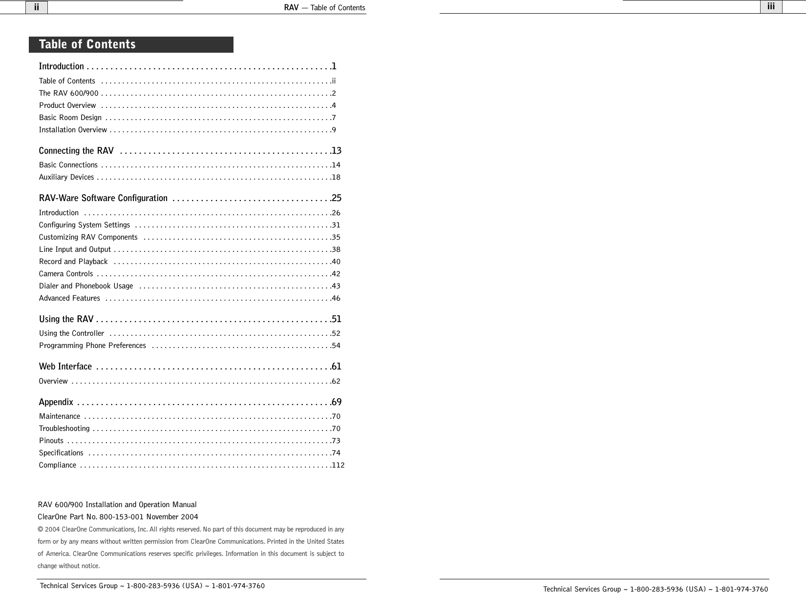
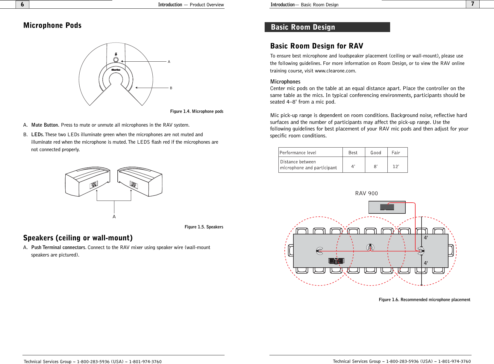
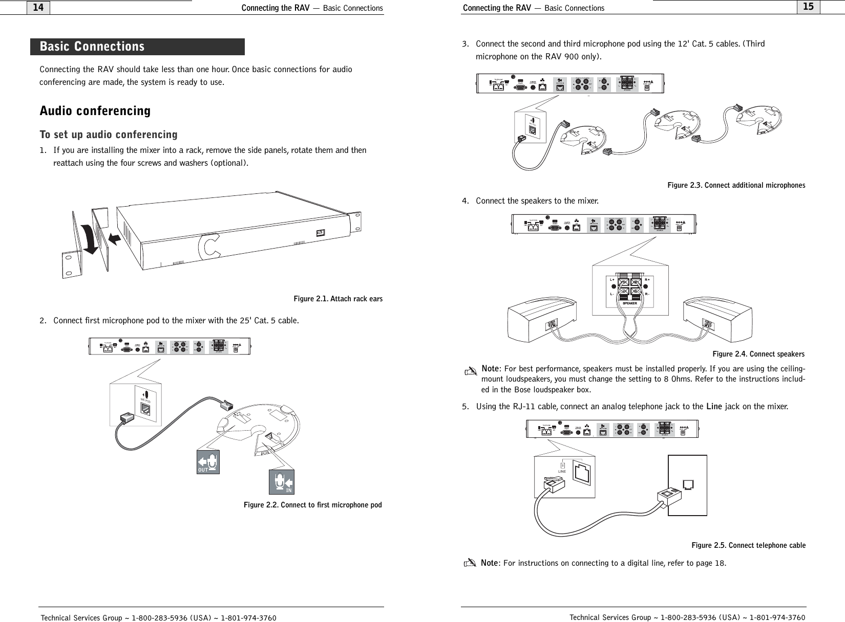
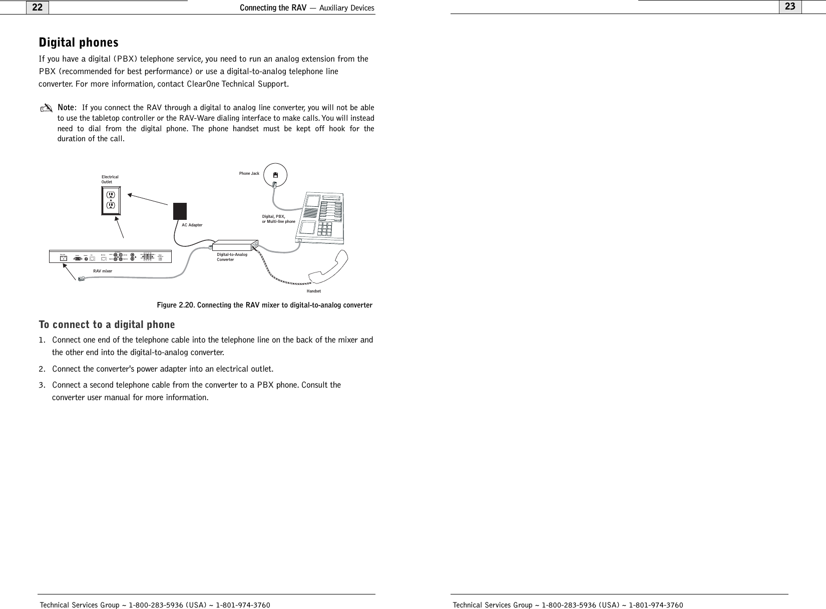
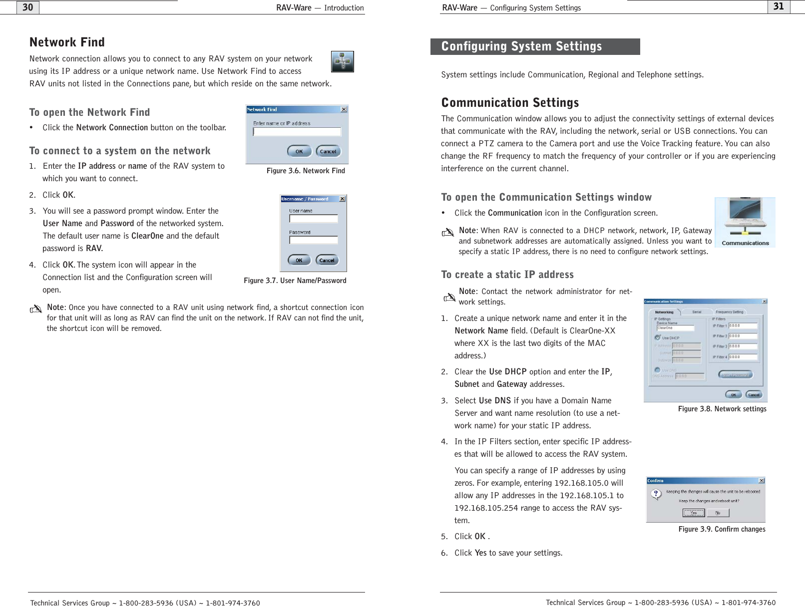
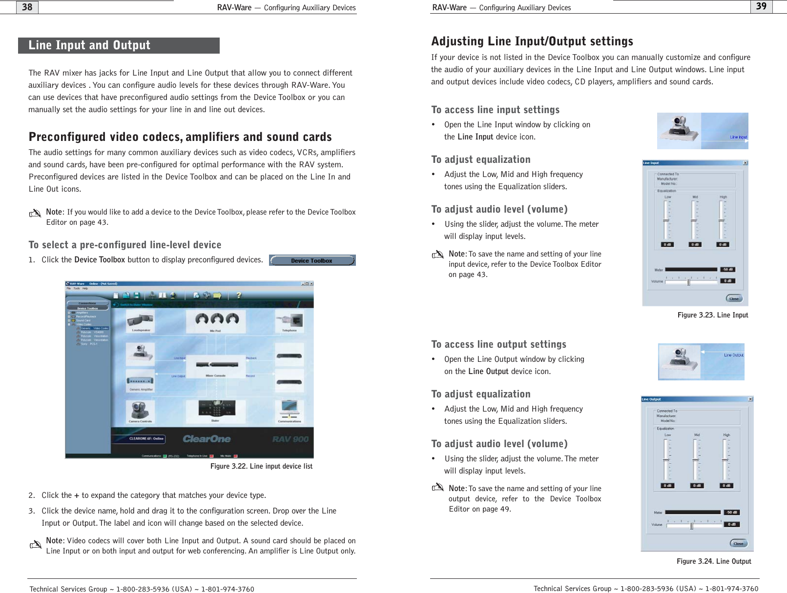
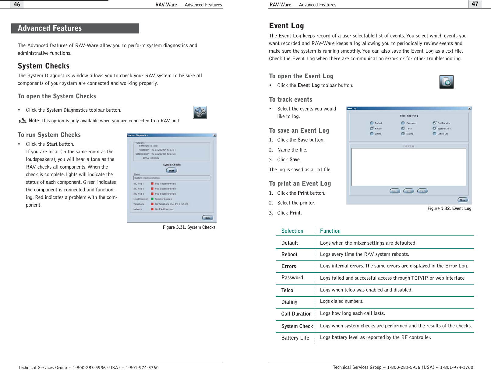
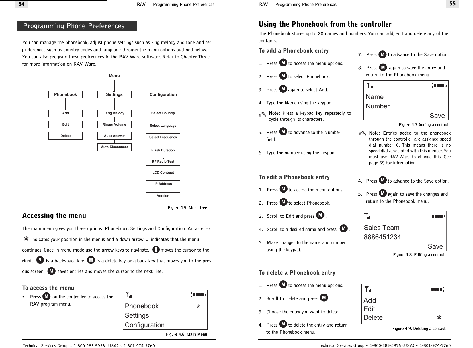
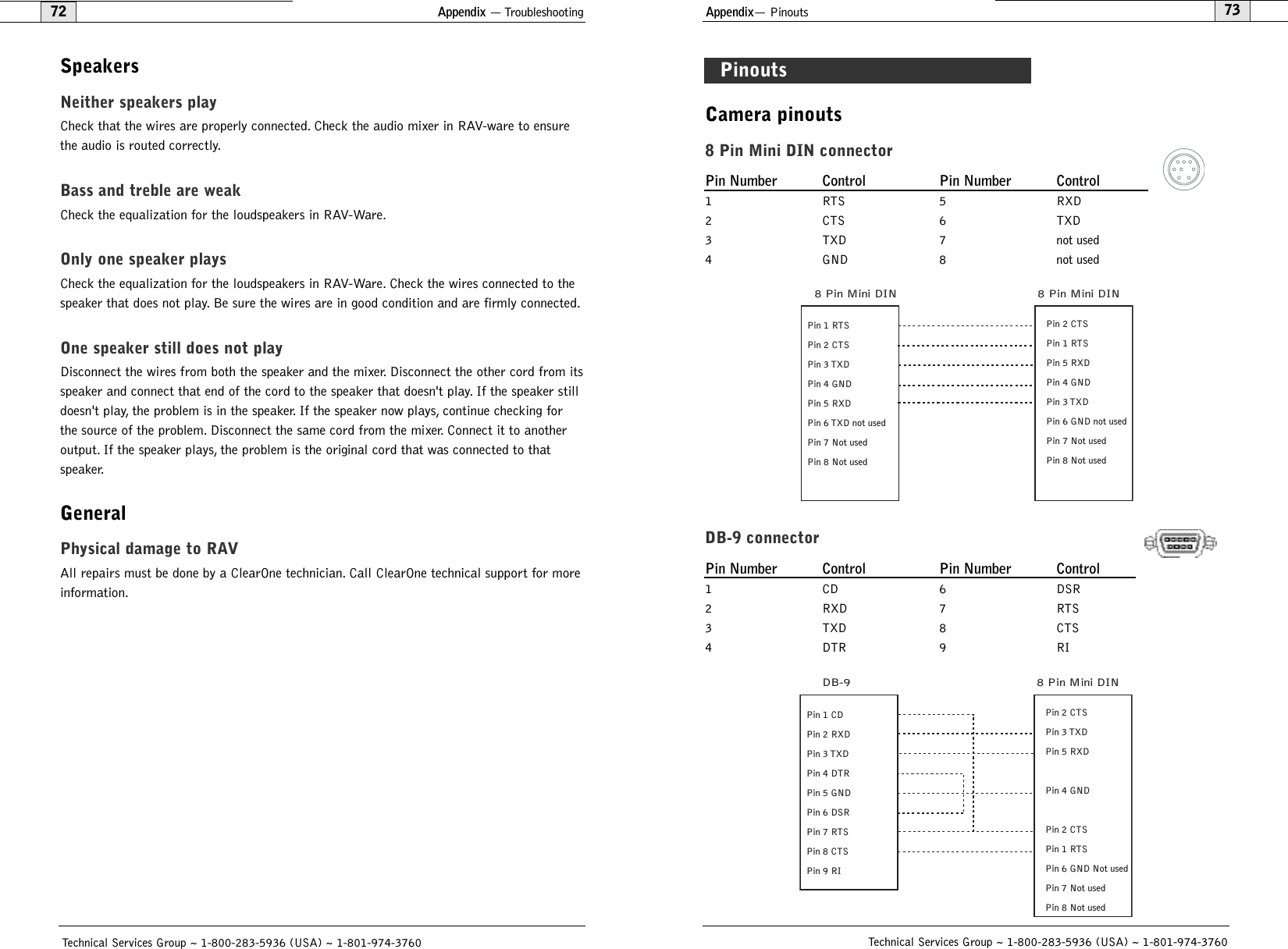
![Appendix— Serial Commands85CALLDUR - Call DurationThis command indicates how long a call has lasted. If no call is in session, this will report 0. At thetime of call termination, this command will automatically be sent out reporting the duration.ARGUMENT DETAILSName Type Size Values UnitsChannel Channel 1 See Group And ChannelsGroup Group 1 17 (R)Reserved 2 0Duration String 8 String of format HR:MN:SSBINARY FORM DETAILSCOMMAND ID:63NUMBER OF ARGUMENTS:3ARGUMENT FORM: <Channel><Group><Reserved><Duration>TEXT FORM DETAILSCOMMAND FORM: DEVICE CALLDUR <Channel> <Duration>CAMBAUD - Camera Control Baud RateThis command selects/reports the baud rate of the camera control serial port.ARGUMENT DETAILSName Type Size Values UnitsValue Unsigned Integer 4 2400, 9600, 19200, 38400(Null to query in text)BINARY FORM DETAILSCOMMAND ID:60NUMBER OF ARGUMENTS:1ARGUMENT FORM: <Value>TEXT FORM DETAILSCOMMAND FORM: DEVICE CAMBAUD [Value] CAMCTRLMODE - Camera Control Port Mode This command sets/reports the camera control port mode.ARGUMENT DETAILSName Type Size Values UnitsValue Unsigned Integer 4 0 = Sony1 = Canon(Null to Query in Text)BINARY FORM DETAILSCOMMAND ID:50NUMBER OF ARGUMENTS:1ARGUMENT FORM: <Value>TEXT FORM DETAILSCOMMAND FORM: DEVICE CAMCTRLMODE [Value]Technical Services Group ~ 1-800-283-5936 (USA) ~ 1-801-974-3760Appendix — Serial Commands84BATTERYLVL - Battery LevelThis command reports the battery level on the remote. If the batteries run low, this command willautomatically be sent out reporting the low indication.ARGUMENT DETAILSName Type Size Values UnitsValue Unsigned Integer 4 0 = battery level unavailable1 = Lowest2345 = Highest(Null to query in text.)BINARY FORM DETAILSCOMMAND ID:65NUMBER OF ARGUMENTS:1ARGUMENT FORM: <Value>TEXT FORM DETAILSCOMMAND FORMDEVICE BATTERYLVL [Value]BAUD - Baud RateThis command selects/reports the baud rate of the serial port.ARGUMENT DETAILSName Type Size Values UnitsValue Unsigned Integer 4 9600, 19200, 38400,57600,115200(Null to query in text)BINARY FORM DETAILSCOMMAND ID:2NUMBER OF ARGUMENTS:1ARGUMENT FORM: <Value>TEXT FORM DETAILSCOMMAND FORM: DEVICE BAUD [Value] Attention: If you are connected to the RAV unit through the serial port, you will need to rebootthe unit before the baud rate and flow control changes take place. If you are connected to theRAV unit through the USB port, changes are made instantly.Technical Services Group ~ 1-800-283-5936 (USA) ~ 1-801-974-3760](https://usermanual.wiki/ClearOne/RAV1/User-Guide-490705-Page-45.png)
![Appendix — Serial Commands87CAMPRESET - Camera Preset Executes a camera preset.There is no query for this command.ARGUMENT DETAILSName Type Size Values UnitsValue Unsigned Integer 4 1 - 10BINARY FORM DETAILSCOMMAND ID:51NUMBER OF ARGUMENTS:1ARGUMENT FORM: <Value>TEXT FORM DETAILSCOMMAND FORM: DEVICE CAMPRESET [Value]CAMPRESETSET - Camera Preset SetupThis command sets the current position of a camera as a camera preset. There is no query for thiscommand.ARGUMENT DETAILSName Type Size Values UnitsPreset Unsigned Integer 2 1 - 10Channel Channel 1 See Group And ChannelsGroup Group 1 19 (V)Label String 16BINARY FORM DETAILSCOMMAND ID:52NUMBER OF ARGUMENTS:5ARGUMENT FORM: <Preset><Channel><Group><Label>TEXT FORM DETAILSCOMMAND FORM: DEVICE CAMPRESETSET <Preset Channel Group Label>Technical Services Group ~ 1-800-283-5936 (USA) ~ 1-801-974-3760Appendix — Serial Commands86CAMFLOW - Camera Control Flow ControlThis command selects/reports the flow control of the camera control serial port on the unit.Hardware flow control is implemented using DTR and DSR.ARGUMENT DETAILSName Type Size Values UnitsValue Unsigned Integer 4 0 = Off1 = On2 = Toggle(Null to query in text)BINARY FORM DETAILSCOMMAND ID:61NUMBER OF ARGUMENTS:1ARGUMENT FORM: <Value>TEXT FORM DETAILSCOMMAND FORM: DEVICE CAMFLOW [Value] CAMMOVE - Move the CameraThis command sends commands to move the camera on the camera control port. There is no queryfor this command.ARGUMENT DETAILSName Type Size Values UnitsChannel Channel 1 See Group And ChannelsGroup Group 1 19 (V)Value Unsigned Integer 2 0 = Stop1 = Pan Right2 = Pan Left3 = Tilt Up4 = Tilt Down5 = Zoom In6 = Zoom OutBINARY FORM DETAILSCOMMAND ID:49NUMBER OF ARGUMENTS:1ARGUMENT FORM: <Channel><Group><Value>TEXT FORM DETAILSCOMMAND FORM: DEVICE CAMMOVE <Channel Group> [Value]Technical Services Group ~ 1-800-283-5936 (USA) ~ 1-801-974-3760](https://usermanual.wiki/ClearOne/RAV1/User-Guide-490705-Page-46.png)
![Appendix — Serial Commands89CAMSWITCHLAG - Camera Switch Time LagThis command set the switch time lag for voice tracking.ARGUMENT DETAILSName Type Size Values UnitsValue Unsigned Float 4 0.00 - 5.00 SBINARY FORM DETAILSCOMMAND ID:76NUMBER OF ARGUMENTS:1ARGUMENT FORM: <Value>TEXT FORM DETAILSCOMMAND FORM: DEVICE CAMSWITCHLAG [Value]CAMTRACK - Camera TrackThis command selects/reports the camera voice tracking mode.ARGUMENT DETAILSName Type Size Values UnitsValue Unsigned Integer 4 0 = Off1 = On2 = Toggle(Null to query in text)BINARY FORM DETAILSCOMMAND ID:57NUMBER OF ARGUMENTS:1ARGUMENT FORM: <Value>TEXT FORM DETAILSCOMMAND FORM: DEVICE CAMTRACK [Value] CAMZOOM - Camera ZoomThis command sets or reports the current Zoom of the camera on the camera control port.ARGUMENT DETAILSName Type Size Values UnitsChannel Channel 1 See Group And ChannelsGroup Group 1 19 (V)Zoom Angle Signed Float 2 If Sony, 6.6 to 65. DegreesIf Canon, 3 to 47.5.(NULL to Query in Text).BINARY FORM DETAILSCOMMAND ID:54NUMBER OF ARGUMENTS:1ARGUMENT FORM: <Channel><Group><Zoom Angle>TEXT FORM DETAILSCOMMAND FORM: DEVICE CAMZOOM <Channel Group> [Zoom]Technical Services Group ~ 1-800-283-5936 (USA) ~ 1-801-974-3760Appendix — Serial Commands88CAMPRESETSET2 - Camera Preset Setup 2This command sets or reports the current camera preset.ARGUMENT DETAILSName Type Size Values UnitsPreset Unsigned Integer 2 1 - 10Channel Channel 1 See Group And ChannelsGroup Group 1 19 (V)Pan Angle Signed Float 2 If Sony, -100 to 100. DegreesIf Canon, -100 to 100.(NULL to Query in Text)Tilt Angle Signed Float 2 If Sony, -25 to 25. DegreesIf Canon, -30 to 90.Zoom Angle Signed Float 4 If Sony, 6.6 to 65. DegreesIf Canon, 3 to 47.5.Label String 16BINARY FORM DETAILSCOMMAND ID:56NUMBER OF ARGUMENTS:7ARGUMENT FORM: <Preset><Channel><Group><Pan><Tilt><Zoom><Label>TEXT FORM DETAILSCOMMAND FORM: DEVICE CAMPRESETSET2 <Preset>[Channel Group Pan Tilt Zoom Label]CAMPOSITION - Camera PositionThis command sets or reports the current position of the camera on the camera control port.ARGUMENT DETAILSName Type Size Values UnitsChannel Channel 1 See Group And ChannelsGroup Group 1 19 (V)Pan Angle Signed Float 2 If Sony, -100 to 100. DegreesIf Canon, -100 to 100.(NULL to Query in Text)Tilt Angle Signed Float 4 If Sony, -25 to 25. DegreesIf Canon, -30 to 30.BINARY FORM DETAILSCOMMAND ID:53NUMBER OF ARGUMENTS:2ARGUMENT FORM: <Channel><Group><Pan Angle><Tilt Angle>TEXT FORM DETAILSCOMMAND FORM: DEVICE CAMPOSITON <Channel Group> [Pan Tilt]Technical Services Group ~ 1-800-283-5936 (USA) ~ 1-801-974-3760](https://usermanual.wiki/ClearOne/RAV1/User-Guide-490705-Page-47.png)
![Appendix — Serial Commands91COUNTRY - Country SelectionThis command sets / reports the country for compliance.ARGUMENT DETAILSName Type Size Values UnitsValue Unsigned Integer 4 1 = US / Canada2 = Europe3 = Mexico4 = Australia / New Zealand5 = South Africa6 = Japan7 = Brazil8 = South Korea9 = China10 = Singapore11 = Taiwan(Null to query in text)BINARY FORM DETAILSCOMMAND ID:40NUMBER OF ARGUMENTS:1ARGUMENT FORM: <Value>TEXT FORM DETAILSCOMMAND FORM: DEVICE COUNTRY [Value]DEFAULT - Default The Unit Sets the unit to factory defaults. There is no query for this command.ARGUMENT DETAILSNoneBINARY FORM DETAILSCOMMAND ID:17NUMBER OF ARGUMENTS:1ARGUMENT FORM: <0>TEXT FORM DETAILSCOMMAND FORM: DEVICE DEFAULTAttention: The unit will need to be rebooted after sending the DEFAULT command.Technical Services Group ~ 1-800-283-5936 (USA) ~ 1-801-974-3760Appendix — Serial Commands90CLEAREFFECT - Clear Effect Wide Band Telco EmulationThis command enables/disables or reports the current status of the clear effect.ARGUMENT DETAILSName Type Size Values UnitsChannel Channel 1 See Group And ChannelsGroup Group 1 17 (T)Value Unsigned Integer 2 0 = Off1 = On2 = Toggle(Null to query in text)BINARY FORM DETAILSCOMMAND ID:66NUMBER OF ARGUMENTS:1ARGUMENT FORM: <Channel><Group><Value>TEXT FORM DETAILSCOMMAND FORM: DEVICE CLEAREFFECT <Channel> [Value] CLOCK - Clock SetThis command sets or reports the current time.ARGUMENT DETAILSName Type Size Values UnitsDate Unsigned Integer 1 1 - 31Month Unsigned Integer 1 1 - 12Year Unsigned Integer 2 2000 - 2099( NULL to Query in Text)Hours Unsigned Integer 1 00 - 23Minutes Unsigned Integer 1 00 - 59Seconds Unsigned Integer 1 00 - 59Day of Week Unsigned Integer 1 1 = Sunday2 = Monday3 = Tuesday4 = Wednesday5 = Thursday6 = Friday7 = SaturdayBINARY FORM DETAILSCOMMAND ID:64NUMBER OF ARGUMENTS:2ARGUMENT FORM: <Date><Month><Year><Hours><Minutes><Seconds><Day>TEXT FORM DETAILSCOMMAND FORM: DEVICE CLOCK [Date Month Year Hours Minutes Seconds Day]Technical Services Group ~ 1-800-283-5936 (USA) ~ 1-801-974-3760](https://usermanual.wiki/ClearOne/RAV1/User-Guide-490705-Page-48.png)
![Appendix — Serial Commands93ENETADDR - Ethernet port IP addressThis command selects/reports the IP address of the Ethernet port on the unit.ARGUMENT DETAILSName Type Size Values UnitsValue IP Address 4 (Null to query in text)BINARY FORM DETAILSCOMMAND ID:21TEXT FORM DETAILSCOMMAND FORM: DEVICE DID [Value]NUMBER OF ARGUMENTS:1ARGUMENT FORM: <Value>TEXT FORM DETAILSCOMMAND FORM: DEVICE ENETADDR [Value] ENETDHCP - Ethernet DHCP SelectionThis command selects/reports the use of DHCP of the Ethernet port on the unit.ARGUMENT DETAILSName Type Size Values UnitsValue Unsigned Integer 4 0 = On1 = Off2 = Toggle(Null to query in text)BINARY FORM DETAILSCOMMAND ID:25NUMBER OF ARGUMENTS:1ARGUMENT FORM: <Value>TEXT FORM DETAILSCOMMAND FORM: DEVICE ENETDHCP [Value] ENETDNSA - Ethernet DNS Server addressesThis command selects/reports the DNS servers IP addresses of the Ethernet port on the unit.ARGUMENT DETAILSName Type Size Values UnitsValue IP Address 4 (Null to query in text)BINARY FORM DETAILSCOMMAND ID:24NUMBER OF ARGUMENTS:1ARGUMENT FORM: <Value>TEXT FORM DETAILSCOMMAND FORM: DEVICE ENETDNSA [Value] Technical Services Group ~ 1-800-283-5936 (USA) ~ 1-801-974-3760Appendix — Serial Commands92DEVICE - Device Identification LabelThis selects/reports the manufacturer identification label of the specific channel.ARGUMENT DETAILSName Type Size Values UnitsChannel Channel 1 See Group And ChannelsGroup Group 1 2, 3, 7(O, M, L)Reserved Unsigned Integer 2 0Label String 32 1 - 32 charactersCLEAR = clear the label(Null to query in text)BINARY FORM DETAILSCOMMAND ID:82NUMBER OF ARGUMENTS:9ARGUMENT FORM: <Channel><Group><Reserved><Value>TEXT FORM DETAILSCOMMAND FORM: DEVICE DEVICE <Channel> <Group> [Value] DIAL - DTMF DialingThis command dials a DTMF sequence or reports back the last sequence dialed.ARGUMENT DETAILSName Type Size Values UnitsChannel Channel 1 See Group And ChannelsGroup Group 1 17 (R)Reserved 2 0Number String 44 1 - 44 Chars of '0' - '9', 'A' - 'D', '*', '#', ','(Null to query last number dialed in text)BINARY FORM DETAILSCOMMAND ID:30NUMBER OF ARGUMENTS:12ARGUMENT FORM: <Channel><Group><Number>TEXT FORM DETAILSCOMMAND FORM: DEVICE DIAL <Channel> [Number] DID - Device IDThis command reports the device id.This command is read only.ARGUMENT DETAILSName Type Size Values UnitsValue Unsigned Integer 4 See Type And Device IDs(Null sent in text, Value returned)BINARY FORM DETAILSCOMMAND ID:3NUMBER OF ARGUMENTS:1ARGUMENT FORM: <Value>Technical Services Group ~ 1-800-283-5936 (USA) ~ 1-801-974-3760](https://usermanual.wiki/ClearOne/RAV1/User-Guide-490705-Page-49.png)
![Appendix — Serial Commands95EQ - EqualizationThis command enables/disables or reports the current status of the equalization on the input or out-put.ARGUMENT DETAILSName Type Size Values UnitsChannel Channel 1 See Group And ChannelsGroup Group 1 2, 7 (O, L)High Gain Signed Float 2 -12.00 - 12.00(Null to query in text)Mid Gain Signed Float 2 -12.00 - 12.00Low Gain Signed Float 2 -12.00 - 12.00BINARY FORM DETAILSCOMMAND ID:67NUMBER OF ARGUMENTS:2ARGUMENT FORM: <Channel><Group><High Gain><Mid Gain><Low Gain>TEXT FORM DETAILSCOMMAND FORM: DEVICE EQ <Channel> <Group> [High Mid Low] EQSEL - Equalization EnableThis command enables/disables or reports the current status of the equalization on the input or out-put.ARGUMENT DETAILSName Type Size Values UnitsChannel Channel 1 See Group And ChannelsGroup Group 1 2, 7 (O, L)Value Unsigned Integer 2 0 = Off1 = On2 = Toggle(NULL to query in text)BINARY FORM DETAILSCOMMAND ID:74NUMBER OF ARGUMENTS:1ARGUMENT FORM: <Channel><Group><Value>TEXT FORM DETAILSCOMMAND FORM: DEVICE EQSEL <Channel> <Group> [Value] Technical Services Group ~ 1-800-283-5936 (USA) ~ 1-801-974-3760Appendix — Serial Commands94ENETDNX - Ethernet DNS SelectionThis command selects/reports the use of DNS of the Ethernet port on the unit.ARGUMENT DETAILSName Type Size Values UnitsValue Unsigned Integer 4 0 = On1 = Off2 = Toggle(Null to query in text)BINARY FORM DETAILSCOMMAND ID:26NUMBER OF ARGUMENTS:1ARGUMENT FORM: <Value>TEXT FORM DETAILSCOMMAND FORM: DEVICE ENETDNS [Value] ENETGATE - Ethernet default Gateway addressThis command selects/reports the default gateway of the Ethernet port on the unit.ARGUMENT DETAILSName Type Size Values UnitsValue IP Address 4 (Null to query in text)BINARY FORM DETAILSCOMMAND ID:23NUMBER OF ARGUMENTS:1ARGUMENT FORM: <Value>TEXT FORM DETAILSCOMMAND FORM: DEVICE ENETGATE [Value] ENETSUBN - Ethernet subnet maskThis command selects/reports the Subnet mask of the Ethernet port on the unit.ARGUMENT DETAILSName Type Size Values UnitsValue IP Address 4 (Null to query in text)BINARY FORM DETAILSCOMMAND ID:22NUMBER OF ARGUMENTS:1ARGUMENT FORM: <Value>TEXT FORM DETAILSCOMMAND FORM: DEVICE ENETSUBN [Value] Technical Services Group ~ 1-800-283-5936 (USA) ~ 1-801-974-3760](https://usermanual.wiki/ClearOne/RAV1/User-Guide-490705-Page-50.png)
![Appendix — Serial Commands97GREPORT - Gate ReportThis command selects/reports the mode of gate status reporting.ARGUMENT DETAILSName Type Size Values UnitsValue Unsigned Integer 4 0 = Off1 = On2 = Toggle(Null to query in text)BINARY FORM DETAILSCOMMAND ID:7NUMBER OF ARGUMENTS:1ARGUMENT FORM: <Value>TEXT FORM DETAILSCOMMAND FORM: DEVICE GREPORT [Value]HOOK - Hook FlashThis command sends a hook flash. There is no query for this command.ARGUMENT DETAILSName Type Size Values UnitsChannel Channel 1 See Group And ChannelsGroup Group 1 17 (R)Reserved 2 0BINARY FORM DETAILSCOMMAND ID:32NUMBER OF ARGUMENTS:1ARGUMENT FORM: <Channel><Group><Reserved>TEXT FORM DETAILSCOMMAND FORM: DEVICE HOOK <Channel> HOOKD - Hook Flash DurationThis command selects/reports the hook flash duration.ARGUMENT DETAILSName Type Size Values UnitsChannel Channel 1 See Group And ChannelsGroup Group 1 17 (R)Value Unsigned Integer 2 50 - 1000 Ms(Null to query in text)BINARY FORM DETAILSCOMMAND ID:33NUMBER OF ARGUMENTS: 1ARGUMENT FORM: <Channel><Group><Value>TEXT FORM DETAILSCOMMAND FORM: DEVICE HOOKD <Channel> [Value] Technical Services Group ~ 1-800-283-5936 (USA) ~ 1-801-974-376096Technical Services Group ~ 1-800-283-5936 (USA) ~ 1-801-974-3760Appendix — Serial CommandsFLOW - Flow ControlThis command selects/reports the flow control of the serial port on the unit. Hardware flow control isimplemented using DTR and DSR.ARGUMENT DETAILSName Type Size Values UnitsValue Unsigned Integer 4 0 = Off1 = On2 = Toggle(Null to query in text)BINARY FORM DETAILSCOMMAND ID:4NUMBER OF ARGUMENTS:1ARGUMENT FORM: <Value>TEXT FORM DETAILSCOMMAND FORM: DEVICE FLOW [Value] GAIN - Gain Adjustment This command changes or reports back the gain for a channel.ARGUMENT DETAILSName Type Size Values UnitsChannel Channel 1 See Group And ChannelsGroup Group 1 2,3,7,16,17 (O,M,L,T,R)Value Signed Float 2 -99.90 - 99.90 **(Null to query in text) DBAbsol / Rel 0 A = AbsoluteR = RelativeNull = RelativeBINARY FORM DETAILSCOMMAND ID:5NUMBER OF ARGUMENTS:1ARGUMENT FORM: <Channel><Group><Value>TEXT FORM DETAILSCOMMAND FORM: DEVICE GAIN <Channel> <Group> [Value] [Absol/Rel]** Note: Values indicate entry range only. Actual internal range of the gain stage is from -14 to 18.Absolute values will be limited to the internal gain range.GATE - Gate StatusThis command reports the gate status of Mics. This command is read only.ARGUMENT DETAILSName Type Size Values UnitsValue Hexadecimal 4 Bits 0 - 8 represent gate status on Mics 1 - 9(Null sent in text, Value returned)BINARY FORM DETAILSCOMMAND ID:6NUMBER OF ARGUMENTS:1ARGUMENT FORM: <Value>TEXT FORM DETAILSCOMMAND FORM: DEVICE GATE [Value]](https://usermanual.wiki/ClearOne/RAV1/User-Guide-490705-Page-51.png)
![Appendix — Serial Commands99Appendix — Serial Commands98Technical Services Group ~ 1-800-283-5936 (USA) ~ 1-801-974-3760LVL - LevelThis command reports the level of a channel.This command is read only.ARGUMENT DETAILSName Type Size Values UnitsChannel Channel 1 See Group And ChannelsGroup Group 1 2, 3, 7, 16, 17(O, M, L,T, R)Position Meter Type 2 See MeterTypeDefinitionsValue Signed Float 4 -99.99 - 99.99 DB(Sent with Null in text,Value returned)BINARY FORM DETAILSCOMMAND ID:9NUMBER OF ARGUMENTS:2ARGUMENT FORM: <Channel><Group><Position><Value>TEXT FORM DETAILSCOMMAND FORM: DEVICE LVL <Channel> <Group> <Position> [Value] LVLREPORT - Level ReportThis command selects/reports the status of level reporting for the specified channel.ARGUMENT DETAILSName Type Size Values UnitsChannel Channel 1 See Group And ChannelsGroup Group 1 2,3,7,16,17 (O,M,L,T,R)Position Meter Type 2 See MeterTypeDefinitionsValue Unsigned Integer 4 0 = Off (Delete from list being reported)1 = On (Add to list being reported)2 = Toggle(Null to query in text)BINARY FORM DETAILSCOMMAND ID:10NUMBER OF ARGUMENTS:2ARGUMENT FORM: <Channel><Group><Position><Value>TEXT FORM DETAILSCOMMAND FORM: DEVICE LVLREPORT <Channel> <Group> <Position> [Value] Note: Level reporting for the unit must also be enabled (LVLREPORTEN).Technical Services Group ~ 1-800-283-5936 (USA) ~ 1-801-974-3760LABEL - LabelThis selects/reports the label of the specific channel or the unit.ARGUMENT DETAILSName Type Size Values UnitsChannel Channel 1 See Group And ChannelsGroup Group 1 2,3,7,9,16,17 (O,M,L,U,T,R)Reserved Unsigned Integer 2 0Label String 32 For group U, 1 - 11 charactersAll other, 1 - 32 charactersIf not group U, CLEAR = clear the label(Null to query in text)BINARY FORM DETAILSCOMMAND ID:8NUMBER OF ARGUMENTS:9ARGUMENT FORM: <Channel><Group><Reserved><Value>TEXT FORM DETAILSCOMMAND FORM: DEVICE LABEL <Channel> <Group> [Value] LOCALNUM -Local NumberThis command sets or reports back the current value of the local number.ARGUMENT DETAILSName Type Size Values UnitsChannel Channel 1 See Group And ChannelsGroup Group 1 17 (R)Reserved 2 0Number String 16 1 - 16 Chars of '0' - '9', 'A' - 'D', '*', '#', ','(Null to query in text)BINARY FORM DETAILSCOMMAND ID:59NUMBER OF ARGUMENTS:5ARGUMENT FORM: <Channel><Group><Number>TEXT FORM DETAILSCOMMAND FORM: DEVICE LOCALNUM <Channel> [Number]](https://usermanual.wiki/ClearOne/RAV1/User-Guide-490705-Page-52.png)
![101Technical Services Group ~ 1-800-283-5936 (USA) ~ 1-801-974-3760Appendix — Serial Commands100LVLREPORTEN - Level Report EnableEnables level reporting for the unit.ARGUMENT DETAILSName Type Size Values UnitsValue Unsigned Integer 4 0 = Turn off reporting but leave current list1 = Turn on reporting2 = Turn off reporting and clear the list(Null to query in text)BINARY FORM DETAILSCOMMAND ID:16NUMBER OF ARGUMENTS:1ARGUMENT FORM: <Value>TEXT FORM DETAILSCOMMAND FORM: DEVICE LVLREPORTEN [Value] MANUFACTURER - Manufacturer Identification LabelThis selects/reports the manufacturer identification label of the specific channel.ARGUMENT DETAILSName Type Size Values UnitsChannel Channel 1 See Group And ChannelsGroup Group 1 2, 3, 7(O, M, L)Reserved Unsigned Integer 2 0Label String 32 1 - 32 charactersCLEAR = clear the label(Null to query in text)BINARY FORM DETAILSCOMMAND ID:81NUMBER OF ARGUMENTS:9ARGUMENT FORM: <Channel><Group><Reserved><Value>TEXT FORM DETAILSCOMMAND FORM: DEVICE MANUFACTURER <Channel> <Group> [Value] Technical Services Group ~ 1-800-283-5936 (USA) ~ 1-801-974-3760Appendix— Serial CommandsMICCAMPRESET - Mic Camera PresetThis command associates a mic with a camera preset for voice tracking.ARGUMENT DETAILSName Type Size Values UnitsChannel Channel 1 See Group And ChannelsGroup Group 1 3 (M)Value Unsigned Integer 2 0 to Clear1 - 10(NULL to Query in Text)BINARY FORM DETAILSCOMMAND ID:55NUMBER OF ARGUMENTS:1ARGUMENT FORM: <Channel><Group><Value>TEXT FORM DETAILSCOMMAND FORM: DEVICE MICCAMPRESET <Channel> [Value]MTRX - Matrix RoutingThis command selects/reports the matrix routing of an input to an output.ARGUMENT DETAILSName Type Size Values UnitsSource Channel Channel 1 See Group And ChannelsSource Group Group 1 3, 7, 17(M, L, R)Destination Channel Channel 1 Group 3 (M) is only allowed all channels.All other groups cannot have the all channel. (See Group And Channels)Destination Group Group 1 2, 16(O, T)Value Unsigned Integer 4 0 = Cross point off1 = Cross point on2 = Toggle(Null to query in text)BINARY FORM DETAILSCOMMAND ID:11NUMBER OF ARGUMENTS:2ARGUMENT FORM: <Src. Ch.><Src. Gp.><Dest. Ch.><Dest. Gp.><Value>TEXT FORM DETAILSCOMMAND FORM: DEVICE MTRX <Src. Ch.> <Src. Gp.> <Dest. Ch.> <Dest. Gp.> [Value]](https://usermanual.wiki/ClearOne/RAV1/User-Guide-490705-Page-53.png)
![Appendix — Serial Commands103Technical Services Group ~ 1-800-283-5936 (USA) ~ 1-801-974-3760Appendix — Serial Commands102MUTE - MuteThis command selects/reports the setting of mute on a channel.ARGUMENT DETAILSName Type Size Values UnitsChannel Channel 1 See Group And ChannelsGroup Group 1 3 (M) (all channels only)Value Unsigned Integer 2 0 = Off1 = On2 = Toggle(Null to query in text)BINARY FORM DETAILSCOMMAND ID:12NUMBER OF ARGUMENTS:1ARGUMENT FORM: <Channel><Group><Value>TEXT FORM DETAILSCOMMAND FORM: DEVICE MUTE <Channel> <Group> [Value]NCSEL - Noise Cancellation SelectThis command enables/disables or reports the current status of noise cancellation.ARGUMENT DETAILSName Type Size Values UnitsChannel Channel 1 See Group And ChannelsGroup Group 1 3,17 (M, R)Value Unsigned Integer 2 0 = Off1 = On2 = Toggle(Null to query in text)BINARY FORM DETAILSCOMMAND ID:62NUMBER OF ARGUMENTS:1ARGUMENT FORM: <Channel><Group><Value>TEXT FORM DETAILSCOMMAND FORM: DEVICE NCSEL <Channel> <Group> [Value] Technical Services Group ~ 1-800-283-5936 (USA) ~ 1-801-974-3760PBDIAL - Dial a PB Entry by NameThis command dials a speed dial number by name.There is no query for this command.ARGUMENT DETAILSName Type Size Values UnitsChannel Channel 1 See Group And ChannelsGroup Group 1 17 (R)Reserved Unsigned Integer 2 0Label String 16 1 - 16 charsBINARY FORM DETAILSCOMMAND ID:36NUMBER OF ARGUMENTS:5ARGUMENT FORM: <Channe><Group><Reserved><Label>TEXT FORM DETAILSCOMMAND FORM: DEVICE PBDIAL <Channel> <Label>PHONEBOOKADD - Adds an Entry to the PhonebookThis command saves an entry in the phonebook.There is no query. No two entries can share the samelabel. An argument error will be returned if an entry already has the name. To change an entry, youmust first delete it and then add it again. If label is blank, the first 20 characters of the number willbe used as the label. Number must not be blank. If an entry already exists with the assigned speeddial it will be overwritten. Speed Dial 34 is the conference number and is always stored first in thePhonebook.The rest of the entries are alphabetized base on Label.ARGUMENT DETAILSName Type Size Values UnitsSpeed Dial Unsigned Integer 4 0 for not assigned to a speed dial1 - 1920 for ConferenceNumber String 44 1 - 44 chars '0' - '9', 'A' - 'D', '*', '#'Label String 16 1 - 16 charsBINARY FORM DETAILSCOMMAND ID:38NUMBER OF ARGUMENTS:16ARGUMENT FORM: <ID><Number><Label>TEXT FORM DETAILSCOMMAND FORM: DEVICE PHONEBOOKADD <ID Number Label>](https://usermanual.wiki/ClearOne/RAV1/User-Guide-490705-Page-54.png)
![Appendix — Serial Commands105REDIAL - Dial the last number againThis command redials the last number.There is no query for this command.ARGUMENT DETAILSName Type Size Values UnitsChannel Channel 1 See Group And ChannelsGroup Group 1 17 (R)Reserved 2 0BINARY FORM DETAILSCOMMAND ID:45NUMBER OF ARGUMENTS:1ARGUMENT FORM: <Channel><Group><Reserved>TEXT FORM DETAILSCOMMAND FORM: DEVICE REDIAL <Channel>RESET - Reset Resets the unit.There is no query for this command.ARGUMENT DETAILSNoneBINARY FORM DETAILSCOMMAND ID:20NUMBER OF ARGUMENTS:1ARGUMENT FORM: <0>TEXT FORM DETAILSCOMMAND FORM: DEVICE RESETRETURN VALUESThe box is reset and the boot up message is displayed.Technical Services Group ~ 1-800-283-5936 (USA) ~ 1-801-974-3760Appendix — Serial Commands104PHONEBOOKCNT - Queries the Number of Entries in the PhonebookThis command queries the number of entries in the phonebook.This command is query only.ARGUMENT DETAILSName Type Size Values UnitsValue Unsigned Integer 4 0 - 20BINARY FORM DETAILSCOMMAND ID:78NUMBER OF ARGUMENTS:1ARGUMENT FORM: <Value>TEXT FORM DETAILSCOMMAND FORM: DEVICE PHONEBOOKCNT <Value>PHONEBOOKDEL - Deletes an Entry to the PhonebookThis command deletes an entry in the phonebook. There is no query.ARGUMENT DETAILSName Type Size Values UnitsLabel String 16 1 - 16 charsBINARY FORM DETAILSCOMMAND ID:77NUMBER OF ARGUMENTS:4ARGUMENT FORM: <Label>TEXT FORM DETAILSCOMMAND FORM: DEVICE PHONEBOOKDEL <Label>PHONEBOOKREAD - Queries A Entry in the Phonebook By IndexThis command queries an entry in the phonebook. This command is query only.ARGUMENT DETAILSName Type Size Values UnitsIndex Unsigned Integer 2 0 - 19 (Must be less than the Number of Phone Book Entries)Speed Dial Unsigned Integer 2 0 for not assigned to a speed dial1 - 1920 for Conference(NULL to query in text)Number String 44 1 - 44 chars '0' - '9', 'A' - 'D', '*', '#'Label String 16 1 - 16 charsBINARY FORM DETAILSCOMMAND ID:79NUMBER OF ARGUMENTS:16ARGUMENT FORM: <Index><Speed Dial><Number><Label>TEXT FORM DETAILSCOMMAND FORM: DEVICE PHONEBOOKREAD <Index> [Speed Number Label]Technical Services Group ~ 1-800-283-5936 (USA) ~ 1-801-974-3760](https://usermanual.wiki/ClearOne/RAV1/User-Guide-490705-Page-55.png)
![Appendix — Serial Commands107Technical Services Group ~ 1-800-283-5936 (USA) ~ 1-801-974-3760Appendix — Serial Commands106RINGERLVL - Audible Ring LevelThis command selects/reports the audible ring level. This command takes longer to execute due to RFcommunications with the remote controllerARGUMENT DETAILSName Type Size Values UnitsChannel Channel 1 See Group And ChannelsGroup Group 1 17 (R)Value Signed Float 2 -12.00 - 4.00 (dB) (Null to query in text)BINARY FORM DETAILSCOMMAND ID:46NUMBER OF ARGUMENTS:1ARGUMENT FORM: <Channel><Group><Value>TEXT FORM DETAILSCOMMAND FORM: DEVICE RINGERLVL <Channel> [Value]RINGERSEL - Audible Ring Melody SelectionThis command sends/reports the audible ring melody. This command takes longer to execute due toRF communications with the remote controllerARGUMENT DETAILSName Type Size Values UnitsChannel Channel 1 See Group And ChannelsGroup Group 1 17 (R)Value Unsigned Integer 2 1 - 3(Null to query in text)BINARY FORM DETAILSCOMMAND ID:35NUMBER OF ARGUMENTS:1ARGUMENT FORM: <Channel><Group><Value>TEXT FORM DETAILSCOMMAND FORM: DEVICE RINGERSEL <Channel> [Value]Technical Services Group ~ 1-800-283-5936 (USA) ~ 1-801-974-3760RFFREQ - RF Frequency SelectionThis command sets / reports the frequency for the RF link to the Remote.The remote must be set tothe same setting.ARGUMENT DETAILSName Type Size Values UnitsValue Unsigned Integer 4 1 - 8For Band 0,1 = 904 MHz2 = 907 MHz3 = 910 MHz4 = 913 MHz5 = 916 MHz6 = 919 MHz7 = 922 MHz8 = 926 MHzFor Band 1,1 = 868 MHz2 = 868.333 MHz3 = 868.667 MHz4 = 869 MHz5 = 869.333 MHz6 = 869.667 MHz7 = 870 MHz8 = 868 MHz(Null to query in text)BINARY FORM DETAILSCOMMAND ID:58NUMBER OF ARGUMENTS:1ARGUMENT FORM: <Value>TEXT FORM DETAILSCOMMAND FORM: DEVICE RFFREQ [Value]RING - Ring IndicationThis command indicates a ringing line.This command is reportable only. It cannot be queried or set.ARGUMENT DETAILSName Type Size Values UnitsChannel Channel 1 See Group And ChannelsGroup Group 1 17 (R)Value Unsigned Integer 2 0 = Ring cycle has stopped1 = Ring cycle has begunBINARY FORM DETAILSCOMMAND ID:34NUMBER OF ARGUMENTS:1ARGUMENT FORM: <Channel><Group><Value>TEXT FORM DETAILSCOMMAND FORM: DEVICE RING <Channel><Value>](https://usermanual.wiki/ClearOne/RAV1/User-Guide-490705-Page-56.png)
![109STEREOMIX - Sets the Input to be a Stereo MixThis command enables/disables or reports the stereo mix status of an input.ARGUMENT DETAILSName Type Size Values UnitsChannel Channel 1 See Group And ChannelsGroup Group 1 7 (L)Value Unsigned Integer 2 0 = On1 = Off2 = Toggle(NULL to query in text)BINARY FORM DETAILSCOMMAND ID:86NUMBER OF ARGUMENTS:1ARGUMENT FORM: <Channel><Group><Value>TEXT FORM DETAILSCOMMAND FORM: DEVICE STEREOMIX <Channel> [Value] SYSCHECKS - System ChecksInitiates the system checks. There is no query for this command.ARGUMENT DETAILSName Type Size Values UnitsSystem HexadecimalInteger 4 00 - Pod 101 - Pod 202 - Pod 303 - Speaker04 - Telephone05 - Network06 - RF Remote (not implemented)All other bits reservedCheck IntegerBINARY FORM DETAILSCOMMAND ID:87NUMBER OF ARGUMENTS:1ARGUMENT FORM: <System Check>TEXT FORM DETAILSCOMMAND FORM: DEVICE SYSCHECKS <System Check>Technical Services Group ~ 1-800-283-5936 (USA) ~ 1-801-974-3760108Appendix— Serial CommandsAppendix — Serial CommandsTechnical Services Group ~ 1-800-283-5936 (USA) ~ 1-801-974-3760RINGERTEST - Audible Ring Melody TestThis command plays the current audible ringer melody. This command is executable only. There is noquery.ARGUMENT DETAILSName Type Size Values UnitsChannel Channel 1 See Group And ChannelsGroup Group 1 17 (R)Reserved Unsigned Integer 2 0BINARY FORM DETAILSCOMMAND ID:83NUMBER OF ARGUMENTS:1ARGUMENT FORM: <Channel><Group><Reserved>TEXT FORM DETAILSCOMMAND FORM: DEVICE RINGERTEST <Channel>SILENCEPRST - Silence Camera PresetThis command associates a camera preset with silence for voice tracking.ARGUMENT DETAILSName Type Size Values UnitsValue Unsigned Integer 4 0 to Clear1 - 10(NULL to Query in Text)BINARY FORM DETAILSCOMMAND ID:75NUMBER OF ARGUMENTS:1ARGUMENT FORM: <Value>TEXT FORM DETAILSCOMMAND FORM: DEVICE SILENCEPRST [Value]SPEEDDIAL - Speed DialingThis command dials a speed dial number by speed dial number. There is no query for this command.ARGUMENT DETAILSName Type Size Values UnitsChannel Channel 1 See Group And ChannelsGroup Group 1 17 (R)Value Unsigned Integer 2 1 - 3334 for ConferenceBINARY FORM DETAILSCOMMAND ID:37NUMBER OF ARGUMENTS:1ARGUMENT FORM: <Channel><Group><Value>TEXT FORM DETAILSCOMMAND FORM: DEVICE SPEEDDIAL <Channel> <Value>](https://usermanual.wiki/ClearOne/RAV1/User-Guide-490705-Page-57.png)
![Appendix— Serial Commands111110Technical Services Group ~ 1-800-283-5936 (USA) ~ 1-801-974-3760UID - Unit IDThis command reports the unit id. This command is read only.ARGUMENT DETAILSName Type Size Values UnitsValue Hexadecimal 4 (Sent with a Null,value returned in text)BINARY FORM DETAILSCOMMAND ID:13NUMBER OF ARGUMENTS:1ARGUMENT FORM: <Value>TEXT FORM DETAILSCOMMAND FORM: DEVICE UID [Value]VER - VersionThis command reports the version of the unit. This command is read only.ARGUMENT DETAILSName Type Size Values UnitsValue String 8 Version of format MM.mm.rr(Sent with a Null in text, value returned)BINARY FORM DETAILSCOMMAND ID:14NUMBER OF ARGUMENTS:2ARGUMENT FORM: <Value>TEXT FORM DETAILSCOMMAND FORM: DEVICE VER [Value]VOLUME - Volume Adjustment This command changes or reports back the gain for the output channel set as the EC reference.ARGUMENT DETAILSName Type Size Values UnitsValue Signed Float 4 -99.90 - 99.90 ** DB(Null to query in text)Absol / Rel 0 A = AbsoluteR = RelativeNull = RelativeBINARY FORM DETAILSCOMMAND ID: 103NUMBER OF ARGUMENTS:1ARGUMENT FORM: <Value>TEXT FORM DETAILSCOMMAND FORM: DEVICE VOLUME [Value] [Absol/Rel]** Note: Values indicate entry range only. Actual internal range of the gain stage is from -14 to 18.Absolute values will be limited to the internal gain range.Appendix — Serial CommandsTechnical Services Group ~ 1-800-283-5936 (USA) ~ 1-801-974-3760TE - Telco EnableThis command selects/reports the hook status.ARGUMENT DETAILSName Type Size Values UnitsChannel Channel 1 See Group And ChannelsGroup Group 1 17 (R)Value Unsigned Integer 2 0 = Off1 = On2 = Toggle(Null to query in text)BINARY FORM DETAILSCOMMAND ID:39NUMBER OF ARGUMENTS:1ARGUMENT FORM: <Channel><Group><Value>TEXT FORM DETAILSCOMMAND FORM: DEVICE TE <Channel> [Value]TELCOLVLCTRL - Telco TX Level Control Enable/ DisableThis command selects/reports the setting of Telco TX level control.ARGUMENT DETAILSName Type Size Values UnitsChannel Channel 1 See Group And ChannelsGroup Group 1 17 (R)Value Unsigned Integer 2 0 = Off1 = On2 = Toggle(Null to query in text)BINARY FORM DETAILSCOMMAND ID:80NUMBER OF ARGUMENTS:1ARGUMENT FORM: <Channel><Group><Value>TEXT FORM DETAILSCOMMAND FORM: DEVICE TELCOLVLCTRL <Channel> [Value]](https://usermanual.wiki/ClearOne/RAV1/User-Guide-490705-Page-58.png)