ClearOne RAV1 ClearOne Communications RAV 600/900 Controller User Manual RAV 69 chap 1
ClearOne, Inc. ClearOne Communications RAV 600/900 Controller RAV 69 chap 1
ClearOne >
Exhibit 8

ClearOne Communications, Inc. ~ 1825 Research Way, Salt Lake City, UT 84119 ~ tel 1-800-945-7730 ~ fax 1-800-933-5107
RAV 600/900 User Manual

iii
Technical Services Group ~ 1-800-283-5936 (USA) ~ 1-801-974-3760
RAV — Table of Contents
ii
Technical Services Group ~ 1-800-283-5936 (USA) ~ 1-801-974-3760
Introduction . . . . . . . . . . . . . . . . . . . . . . . . . . . . . . . . . . . . . . . . . . . . . . . . . . . .1
Table of Contents . . . . . . . . . . . . . . . . . . . . . . . . . . . . . . . . . . . . . . . . . . . . . . . . . . . . . . .ii
The RAV 600/900 . . . . . . . . . . . . . . . . . . . . . . . . . . . . . . . . . . . . . . . . . . . . . . . . . . . . . . .2
Product Overview . . . . . . . . . . . . . . . . . . . . . . . . . . . . . . . . . . . . . . . . . . . . . . . . . . . . . . .4
Basic Room Design . . . . . . . . . . . . . . . . . . . . . . . . . . . . . . . . . . . . . . . . . . . . . . . . . . . . . .7
Installation Overview . . . . . . . . . . . . . . . . . . . . . . . . . . . . . . . . . . . . . . . . . . . . . . . . . . . . .9
Connecting the RAV . . . . . . . . . . . . . . . . . . . . . . . . . . . . . . . . . . . . . . . . . . . . .13
Basic Connections . . . . . . . . . . . . . . . . . . . . . . . . . . . . . . . . . . . . . . . . . . . . . . . . . . . . . . .14
Auxiliary Devices . . . . . . . . . . . . . . . . . . . . . . . . . . . . . . . . . . . . . . . . . . . . . . . . . . . . . . . .18
RAV-Ware Software Configuration . . . . . . . . . . . . . . . . . . . . . . . . . . . . . . . . . .25
Introduction . . . . . . . . . . . . . . . . . . . . . . . . . . . . . . . . . . . . . . . . . . . . . . . . . . . . . . . . . . .26
Configuring System Settings . . . . . . . . . . . . . . . . . . . . . . . . . . . . . . . . . . . . . . . . . . . . . . .31
Customizing RAV Components . . . . . . . . . . . . . . . . . . . . . . . . . . . . . . . . . . . . . . . . . . . . .35
Line Input and Output . . . . . . . . . . . . . . . . . . . . . . . . . . . . . . . . . . . . . . . . . . . . . . . . . . . .38
Record and Playback . . . . . . . . . . . . . . . . . . . . . . . . . . . . . . . . . . . . . . . . . . . . . . . . . . . .40
Camera Controls . . . . . . . . . . . . . . . . . . . . . . . . . . . . . . . . . . . . . . . . . . . . . . . . . . . . . . . .42
Dialer and Phonebook Usage . . . . . . . . . . . . . . . . . . . . . . . . . . . . . . . . . . . . . . . . . . . . . .43
Advanced Features . . . . . . . . . . . . . . . . . . . . . . . . . . . . . . . . . . . . . . . . . . . . . . . . . . . . . .46
Using the RAV . . . . . . . . . . . . . . . . . . . . . . . . . . . . . . . . . . . . . . . . . . . . . . . . . .51
Using the Controller . . . . . . . . . . . . . . . . . . . . . . . . . . . . . . . . . . . . . . . . . . . . . . . . . . . . .52
Programming Phone Preferences . . . . . . . . . . . . . . . . . . . . . . . . . . . . . . . . . . . . . . . . . . .54
Web Interface . . . . . . . . . . . . . . . . . . . . . . . . . . . . . . . . . . . . . . . . . . . . . . . . . .61
Overview . . . . . . . . . . . . . . . . . . . . . . . . . . . . . . . . . . . . . . . . . . . . . . . . . . . . . . . . . . . . . .62
Appendix . . . . . . . . . . . . . . . . . . . . . . . . . . . . . . . . . . . . . . . . . . . . . . . . . . . . . .69
Maintenance . . . . . . . . . . . . . . . . . . . . . . . . . . . . . . . . . . . . . . . . . . . . . . . . . . . . . . . . . . .70
Troubleshooting . . . . . . . . . . . . . . . . . . . . . . . . . . . . . . . . . . . . . . . . . . . . . . . . . . . . . . . . .70
Pinouts . . . . . . . . . . . . . . . . . . . . . . . . . . . . . . . . . . . . . . . . . . . . . . . . . . . . . . . . . . . . . . .73
Specifications . . . . . . . . . . . . . . . . . . . . . . . . . . . . . . . . . . . . . . . . . . . . . . . . . . . . . . . . . .74
Compliance . . . . . . . . . . . . . . . . . . . . . . . . . . . . . . . . . . . . . . . . . . . . . . . . . . . . . . . . . . . .112
© 2004 ClearOne Communications, Inc. All rights reserved. No part of this document may be reproduced in any
form or by any means without written permission from ClearOne Communications. Printed in the United States
of America. ClearOne Communications reserves specific privileges. Information in this document is subject to
change without notice.
RAV 600/900 Installation and Operation Manual
ClearOne Part No. 800-153-001 November 2004
Table of Contents

Introduction 1
Introduction— The RAV 600/900
3
Technical Services Group ~ 1-800-283-5936 (USA) ~ 1-801-974-3760
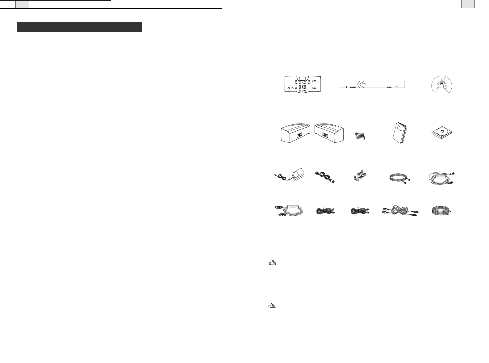
Unpacking
Carefully remove all components of the RAV system from the packaging. Ensure that you
received the following items:
RAV 600/900
Note: Rack mount ears come attached to the Mixer box. Refer to installation instructions
for more information.
If any parts are missing, please call the Technical Support Group at
1-800-283-5936 (USA) or 1-801-974-3760.
Note
: ClearOne is not responsible for product damage incurred during shipment. You must
make claims directly with the carrier. Inspect your shipment carefully for obvious signs of
damage. If the shipment appears damaged, retain the original boxes and packing material for
inspection by the carrier. Contact your carrier immediately.
Introduction — The RAV 600/900
2
Technical Services Group ~ 1-800-283-5936 (USA) ~ 1-801-974-3760
The RAV product line is the first out-of-the-box room audio conferencing solution with the
sound quality and flexibility of a professionally installed system. The RAV includes an audio
conferencing mixer that uses distributed acoustical echo cancelling technology to provide the
most intelligible full duplex audio conference experience available. Features include:
• Audio mixer for high quality audio performance in all acoustical environments.
• Internal telephone hybrid with touch-tone dialing capability, call controls including
auto-answer, flash duration adjustment, ringer adjustment and phonebook with speed dial
capabilities
• Microphone pods provide 360º audio pickup so every participant within the microphone
pick-up range can be heard
• Ceiling or wall-mount Bose®speakers allow everyone in the room to experience rich,
natural sounding audio.
Services and support
If you need additional information on how to install, set up or operate your RAV 600/900,
please contact us. We welcome and encourage your comments so we can continue to improve
our products and serve your needs.
Product returns
All product returns require a return material authorization (RMA) number. Please contact
ClearOne Technical Support before attempting to return your product. Make sure you return
all the items that shipped with your product and include a brief description of how the
product was being used when the problem occurred.
Technical support Sales and customer service
Tel: 1-800-283 5936 (USA) or
1-801-974-3760
Tel: 1-800-945-7730 (USA) or
1-801-975-7200
Fax: 1-801-974-3669 Fax: 1-800-933-5107 (USA) or
1-801-977-0087
E-mail: tech.support@clearone.com
Web: www.clearone.com
E-mail: sales@clearone.com
The RAV 600/900
Controller Mixer
Ceiling-Mount Speakers
or
Wall-Mount Speakers
Mic Pods
Qty: 2 with RAV 600
Qty: 3 with RAV 900
123456789
POWER
-30-10 -4 0+4 +8+12
600
R A V
MUTE
CONFERENCE
ON/OFF FLASH REDIAL
123
456
789
0#
*
ABC DEF
GHI JKL MNO
PQRS TUV WXYZ
HELP
LINE
PAUSE
MENU
ENTER
DOWN UP
PHONEBOOK
CLEAR
DOWN UP
VOLUME
RAV Quick Start Guide
AAA Batteries
Qty: 4
Power Supply 12' Telephone Cable 7 ' RJ-45 Cable
Qty: 4 pair
Screw/Washer Rack Kit
Qty: 4
6' USB Cable 25' RJ-45 Cable
Qty: 1 for RAV 600
Qty: 2 for RAV 900
12' RJ-45 Cable 50' Speaker Cable
Qty: 2
6' Power Cord
6' RCA Cable
Qty: 2
RAV-Ware Installation
and Manual CD
Figure 1.1 RAV unpacking
Controller
The controller allows you to manage all calls, program user preferences and adjust settings
for your RAV.
Key Functions
MUTE
CONFERENCE
ON/OFF FLASH REDIAL
123
456
789
0#
*
ABC DEF
GHI JKL MNO
PQRS TUV WXYZ
HELP
LINE
PAUSE
MENU
ENTER
DOWN UP
PHONEBOOK
CLEAR
DOWN UP
VOLUME
Introduction— Product Overview
5
Technical Services Group ~ 1-800-283-5936 (USA) ~ 1-801-974-3760
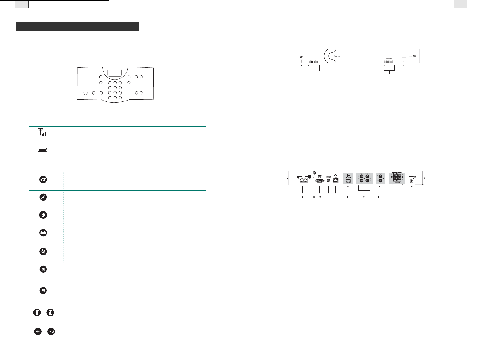
Mixer
Front
A.
Telephone LED
.This indicator lights red when the mixer is powered, but RAV is not in use.
The indicator lights green when the RAV is in use and flashes green during an incoming
call.
B.
Microphone status LEDs
. Nine indicators (RAV 900) or six indicators (RAV 600) indicate
the activation status of the microphone elements. When a microphone element is activated,
the corresponding LED lights green. When microphones are muted, all LEDs turn red.
C.
Meter LEDs.
These LEDs represent the output level from all audio inputs.
D.
USB port
.This port enables USB connection to a PC.
Back
A.
Telephone Set, Line
. RJ-11 connection to an analog telephone jack and an analog
telephone set.
B.
RF antenna connector
. Connect the external RF antenna to this port.
C. RS-232
. RS-232 control port for connection to a control system such as AMX or Crestron
or to a computer.
D.
Camera Control
. VISCA camera control port. This connection enables microphone activa-
tion to trigger camera presets (voice tracking).
E.
LAN
.This is a 10/100 BaseT auto-detecting Ethernet port for system control through a
data network.
F.
Mic Pod In
. Use a Cat. 5 cable with RJ-45 connectors to connect the microphone pods.
G.
Playback In/Record Out
. RCA connection to recording devices such as a VCR.
H.
Line In/Out
. RCA connection to a codec, amplifier or sound card.
I.
Speaker Output
. Use speaker wire to connect these push terminals to the Bose
loudspeakers.
J.
Power. 12 VDC.
Power supply.
CDAB
Figure 1.2. Mixer front
Figure 1.3. Mixer back
Introduction — Product Overview
4
Technical Services Group ~ 1-800-283-5936 (USA) ~ 1-801-974-3760
Product Overview
FLASH
REDIAL
Function
Press once to dial the last number called.
Key
Press once to mute microphones during a call.
Press again to unmute.
Press to activate the phone and access the dial tone. Press
again to hang up the phone.
Press once to dial stored numbers.
When you are in the Menu, use this key to delete entries or to go back
to the previous screen.
Press to dial your conferencing services provider. This number must
be programmed to speed dial number 20.
Press to use call forwarding, access call waiting, or make a three-way
conference call (if supported by your telephone service).
Press down or up to navigate through the menu and phonebook.
Press while on a call to adjust call volume and ringer .
DOWN UP
STATUS
Press once to access the controller programming menu.
Once you are in the Menu, this key serves as the Enter key.
MENU
ENTER
PHONEBOOK
CLEAR
ON/OFF
VOLUME
MUTE
Indicates battery level
LCD Icon
ANTENNA
SIGNAL
BATTERY
Function
Indicates commands are received and awknowledged by base unit
and represents the signal strength from the base unit to the controller.
Introduction— Basic Room Design
7
Technical Services Group ~ 1-800-283-5936 (USA) ~ 1-801-974-3760
Basic Room Design for RAV
To ensure best microphone and loudspeaker placement (ceiling or wall-mount), please use
the following guidelines. For more information on Room Design, or to view the RAV online
training course, visit www.clearone.com.
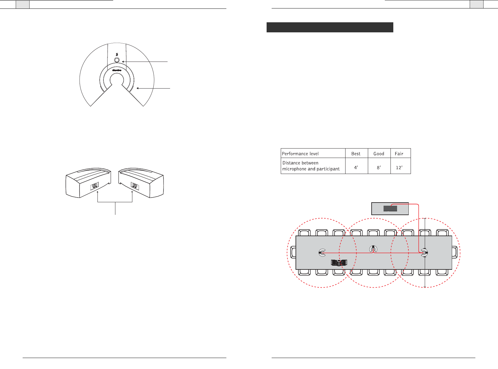
Microphones
Center mic pods on the table at an equal distance apart. Place the controller on the
same table as the mics. In typical conferencing environments, participants should be
seated 4–8' from a mic pod.
Mic pick-up range is dependent on room conditions. Background noise, reflective hard
surfaces and the number of participants may affect the pick-up range. Use the
following guidelines for best placement of your RAV mic pods and then adjust for your
specific room conditions.
RAV 900
4'
4'
Figure 1.6. Recommended microphone placement
Introduction — Product Overview
6
Technical Services Group ~ 1-800-283-5936 (USA) ~ 1-801-974-3760
Microphone Pods
A.
Mute Button.
Press to mute or unmute all microphones in the RAV system.
B.
LEDs
.These two LEDs illuminate green when the microphones are not muted and
illuminate red when the microphone is muted. The LEDS flash red if the microphones are
not connected properly.
Speakers (ceiling or wall-mount)
A.
Push Terminal connectors
. Connect to the RAV mixer using speaker wire (wall-mount
speakers are pictured).
A
B
A
Figure 1.4. Microphone pods
Figure 1.5. Speakers
Basic Room Design
Introduction— Installation Overview
9
Technical Services Group ~ 1-800-283-5936 (USA) ~ 1-801-974-3760
Introduction — Basic Room Design
8
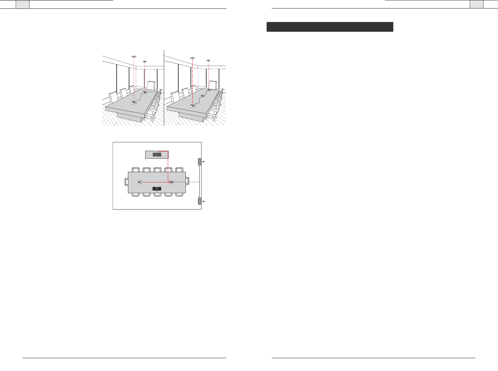
Loudspeakers
Ceiling-mount loudspeakers
For best performance, ceiling loud-
speakers should be installed direct-
ly above the microphone pods. If
you have a RAV 900 with three
mic pods, install the ceiling
loudspeakers above the first and
third mic pods. The ceiling speakers
must be set to 8 Ohms. Please
refer to the Bose user manual for
instructions.
Wall-mount loudspeakers
Place the left channel loudspeaker
on the left side of the room and the
right channel loudspeaker on the
right. (Refer to the label on the
back of each loudspeaker.) Make
sure the back of each loudspeaker
is parallel to the front wall.
For best controller performance
• Do not install the RAV mixer in a metal cabinet unless you are using the remote antenna
accessory.
• Keep the mixer within line of sight of the controller, such as on the top of a credenza.
• Ensure antenna is connected to the back of the mixer and is pointed up.
• If installing the mixer in an equipment rack, make sure it is placed at or near the top of the
rack.
For best audio performance
• Use the provided cables.
• Do not move microphones while on a call.
• Speak at a normal conversation level and direct your voice toward the microphones.
• Do not place microphones next to fans, projectors or computers.
Technical Services Group ~ 1-800-283-5936 (USA) ~ 1-801-974-3760
Read the user manual
Please read through the RAV Quick Start Guide and print User Manual to familiarize
yourself with the RAV system. Refer to the Help File in RAV-Ware for information on the
software. Read through all requirements and safety information to be sure you set up and
configure your RAV correctly.
Make sure your network is ready
Review all system requirements. Then check with your network administrator to be sure your
network meets all the RAV requirements.
Connect cables
Connect all cables. If you are planning on using the RAV for web or videoconferencing, you’ll
need to connect peripheral equipment. See pages 14–22.
Install software
Install RAV-Ware and then use to adjust sound levels and to configure settings for addition-
al equipment such as a video codec or a recording device. See pages 26–49.
Begin using
Use the controller to answer and make calls. See pages 52–59.
Installation Overview
RAV 600
6'
6'
Loudspeaker
Loudspeaker
Figure 1.8 Recommended wall-mount speaker placement
Ceiling Speakers Ceiling Speakers
Figure 1.7 Recommended ceiling-mount speaker placement
11
Technical Services Group ~ 1-800-283-5936 (USA) ~ 1-801-974-3760
Introduction — Installation Overview
10
Technical Services Group ~ 1-800-283-5936 (USA) ~ 1-801-974-3760
System Requirements
Note
: Using a USB to serial adapter is not recommended.
Network information
To use RAV over a local area network (LAN), you need to know if the LAN uses Dynamic
Host Configuration Protocol (DHCP) or if you need a static IP address.
If the LAN uses DHCP, there is no need to make any network adjustments unless you want
to assign a static IP address.
If the LAN does not use DHCP, gather the following information prior to LAN setup:
• The IP address to be assigned to the RAV
• The subnet mask
• The IP address of the default gateway
Operating System and RAM
Windows 98 64 MB RAM
Windows 2000 256 MB RAM
Windows XP 256 MB RAM
Processor 300 MHz Pentium III or better
Monitor 1024 x 768 SVGA (16 bit) high color
Video Card SVGA 1024 x 768 minimum
Free Hard Disk Space 20 MB minimum
RS-232 COM port Up to 115,200 baud rate
USB port USB 1.1–2.0
Macromedia Flash Player 6.0
Component Requirement

Connecting the RAV 2
15
Technical Services Group ~ 1-800-283-5936 (USA) ~ 1-801-974-3760
Connecting the RAV — Basic Connections
14
Connecting the RAV — Basic Connections
3. Connect the second and third microphone pod using the 12' Cat. 5 cables. (Third
microphone on the RAV 900 only).
4. Connect the speakers to the mixer.
Note
: For best performance, speakers must be installed properly. If you are using the ceiling-
mount loudspeakers, you must change the setting to 8 Ohms. Refer to the instructions includ-
ed in the Bose loudspeaker box.
5. Using the RJ-11 cable, connect an analog telephone jack to the
Line
jack on the mixer.
Note
: For instructions on connecting to a digital line, refer to page 18.
L +
L -
R +
R -
SPEAKER
Figure 2.4. Connect speakers
MIC POD
Figure 2.3. Connect additional microphones
LINE
Figure 2.5. Connect telephone cable
Technical Services Group ~ 1-800-283-5936 (USA) ~ 1-801-974-3760
Connecting the RAV should take less than one hour. Once basic connections for audio
conferencing are made, the system is ready to use.
Audio conferencing
To set up audio conferencing
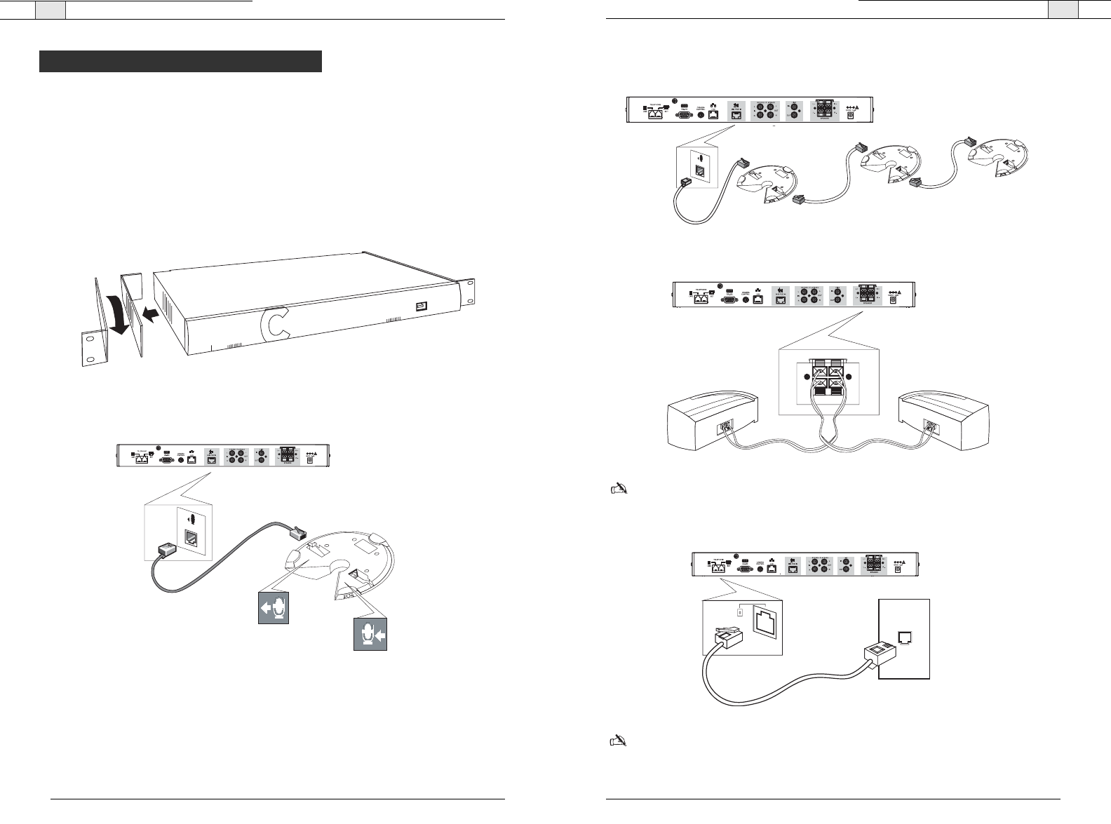
1. If you are installing the mixer into a rack, remove the side panels, rotate them and then
reattach using the four screws and washers (optional).
2. Connect first microphone pod to the mixer with the 25' Cat. 5 cable.
MIC POD
OUT
IN
Basic Connections
Figure 2.2. Connect to first microphone pod
Figure 2.1. Attach rack ears
Connecting the RAV— Basic Connections
17
Technical Services Group ~ 1-800-283-5936 (USA) ~ 1-801-974-3760
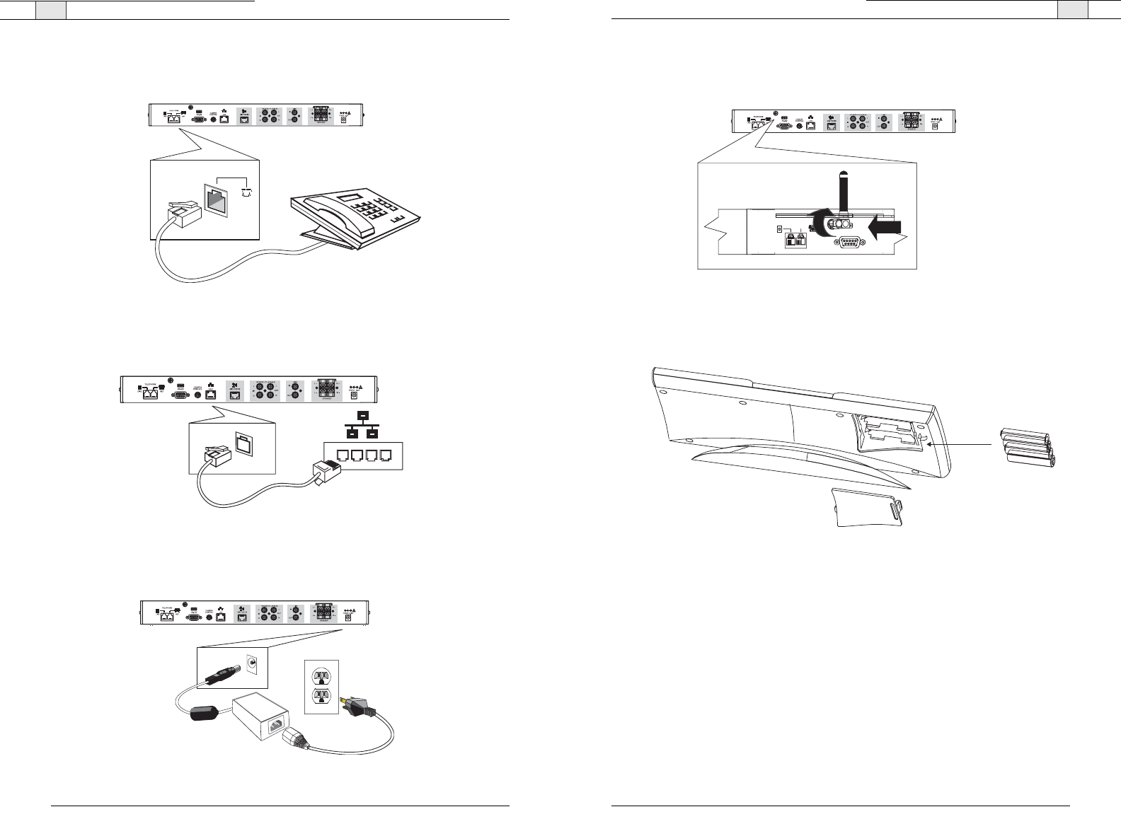
9. Attach the external antenna and turn it so the it is in an upright position.
10. Insert four AAA batteries into the RF controller.
Figure 2.9. Attach external antenna
TELEPHONE
LINE
RS-232
SET
16
Connecting the RAV — Basic Connections
Technical Services Group ~ 1-800-283-5936 (USA) ~ 1-801-974-3760
6. Using an RJ-11 cable (not supplied), connect an analog telephone set to the
Set
jack on
the mixer. (optional)
7. Using the 7' Cat. 5 cable, connect the mixer to the network. (Network settings can be
changed in RAV-Ware.)
8. Using the power supply cords, connect the mixer to an electrical outlet.
Figure 2.7. Connection to network
Figure 2.8. Connection to electrical outlet
SET
Figure 2.6. Connection to network
4 AAA Batterie
s
Back of Controller
Figure 2.10. Insert batteries
Connecting the RAV— Auxiliary Devices
19
To connect to a sound card
1. Using an RCA cable, connect the
Line In
on the RAV mixer to the line out on a sound card.
2. Using an RCA cable, connect the Line Out on the RAV mixer to the line in on a sound card.
To connect to amplifier
• Using an RCA cable, connect the
Line Out
on the RAV mixer to the line in on an amplifier.
or
• Using an RCA cable, connect the Record Out on the RAV mixer to the line in on a sound
card.
Note: User RAV-Ware to adjust the equalization and volume of these devices. Refer to pages
38–42 for more information.
Technical Services Group ~ 1-800-283-5936 (USA) ~ 1-801-974-3760
Connecting the RAV— Auxiliary Devices
18
Technical Services Group ~ 1-800-283-5936 (USA) ~ 1-801-974-3760
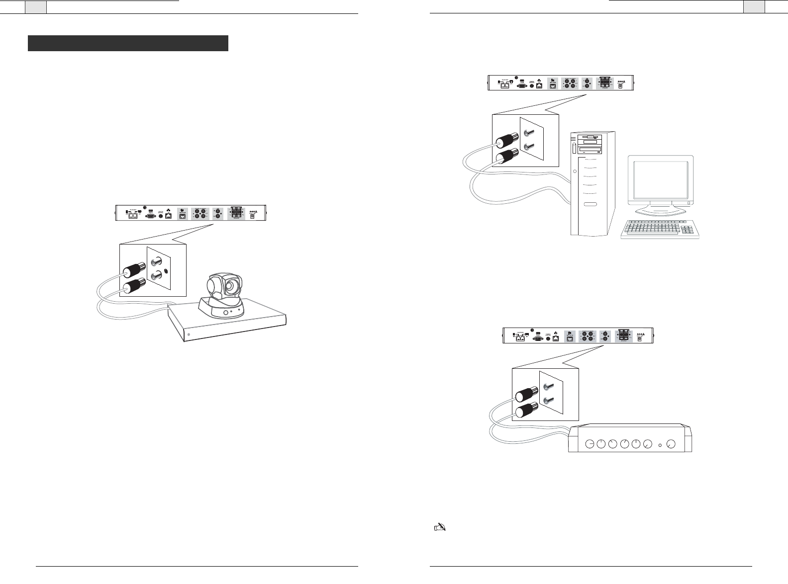
The mixer allows connection to a number of different audio and video peripherals, such as
video codecs, VCRs, cameras and computers.
Connecting video codecs, amplifiers and sound cards
Line input/output devices such as video codecs, amplifiers and sound cards can be connected
to the Line In and Line Out connectors on the RAV mixer. These connectors are
mono-audio.
To connect to a video codec
1. Using an RCA cable, connect the
Line In
on the RAV mixer to the line out on a video
codec.
2. Using an RCA cable, connect the Line Out on the RAV mixer to the line in on a video
codec.
IN
OUT
LINE
Figure 2.13. Connecting a Line In/Out device
Auxiliary Devices
IN
OUT
IN
OUT
Figure 2.14. Connecting a Line In/Out device
Figure 2.15. Connecting a Line In/Out device
21
20
Connecting the RAV— Auxiliary Devices
Technical Services Group ~ 1-800-283-5936 (USA) ~ 1-801-974-3760
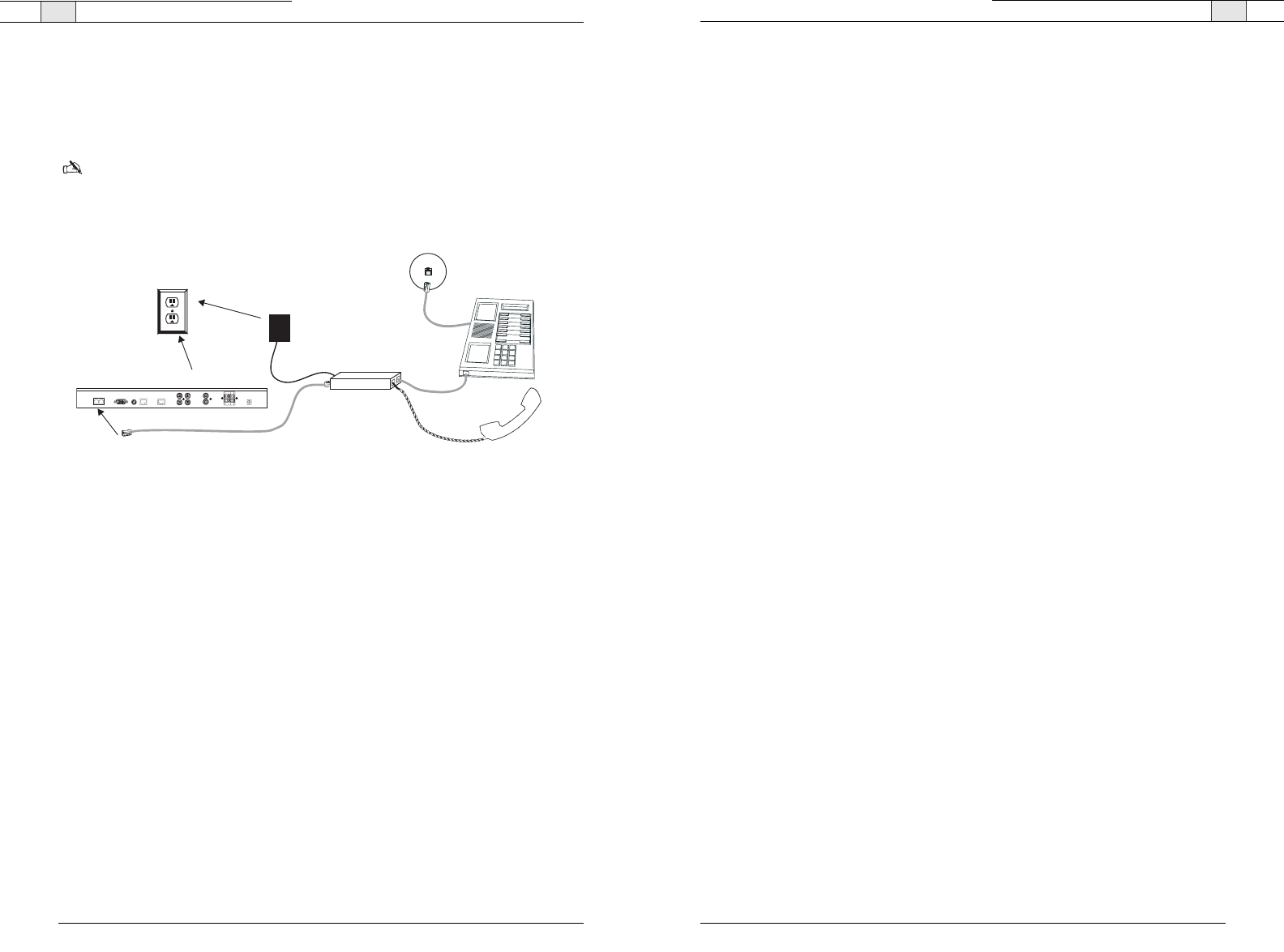
Connecting for serial control
You can connect a computer or a control device, such as an AMX or Crestron, to the RAV
mixer through the serial control port.
To connect a computer serial port
• Connect computer to
Control
port on the back of the mixer using a standard serial cable.
Connecting for USB control
You can connect a computer to the RAV to access RAV-Ware through the USB port.
To connect a computer through the USB port
• Connect computer to the
USB
port on the front of the mixer using a USB cable.
Note
: The USB drivers are installed when you install RAV-Ware.
123456789
POWER
-30 -10 -4 0 +4 +8 +12
600
R A V
Figure 2.18. Connecting a computer serially
Figure 2.19. Connecting a computer through the USB
Connecting the RAV — Auxiliary Devices
Technical Services Group ~ 1-800-283-5936 (USA) ~ 1-801-974-3760
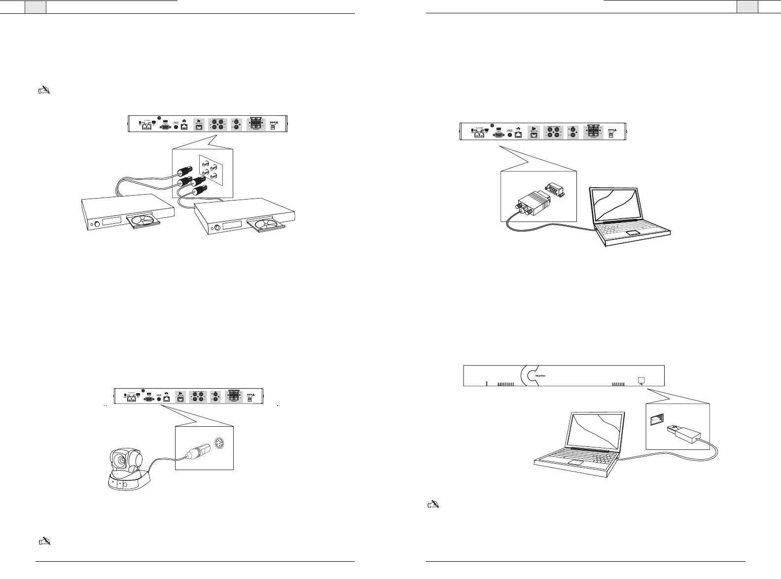
Connecting VCRs and DVD players
Record/Playback offers stereo audio input and output. You can record your audio/video
conference or play audio using a playback device such as a VCR or DVD player.
Note
: You can also connect a mono-signal device or a non-record/playback device to these
line in/out connectors.
To connect to record/playback
• For recording, connect the
Left
and
Right audio Out
on the RAV to the left and right audio
in on the VCR or DVD player.
• For playback, connect the
Left
and
Right audio In
on the RAV to the left and right out on
the VCR or DVD player.
Connecting PTZ cameras
The RAV system provides voice tracking capabilities through VISCA control port connection
to a Pan, Tilt, Zoom camera. Voice Tracking allows the camera to move to preset positions
based on microphone activation. For instructions on programming the presets, see page 36.
To add a camera
• Connect the camera to the
Camera Control
port on the mixer.
Note
: The camera video signals connect to a video codec.
Figure 2.17. Connecting a camera
RECORD / AUX
L
R
L
R
OUT
Figure 2.16. Connecting a Record/Playback device
23
22
Technical Services Group ~ 1-800-283-5936 (USA) ~ 1-801-974-3760Technical Services Group ~ 1-800-283-5936 (USA) ~ 1-801-974-3760
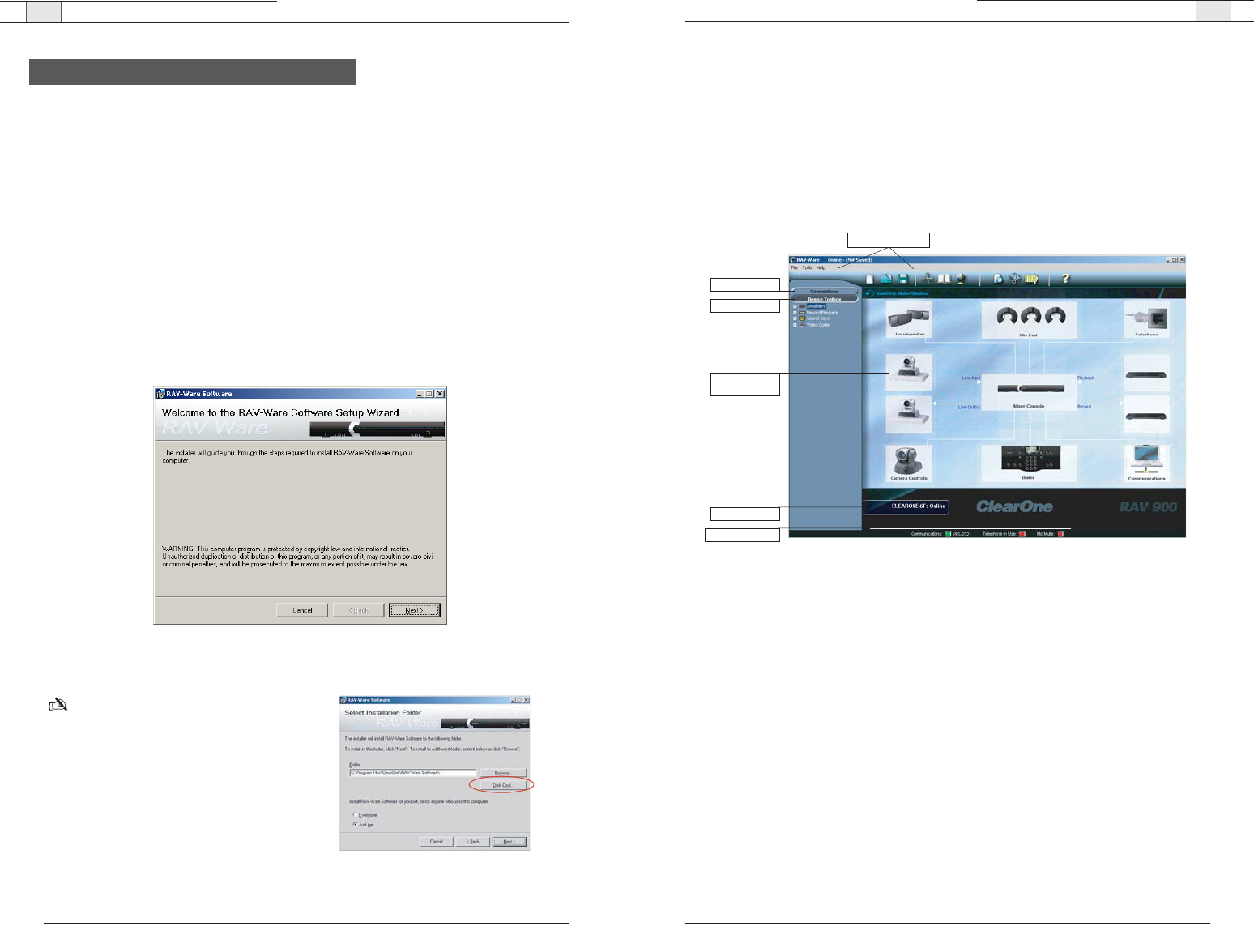
Digital phones
If you have a digital (PBX) telephone service, you need to run an analog extension from the
PBX (recommended for best performance) or use a digital-to-analog telephone line
converter. For more information, contact ClearOne Technical Support.
Note: If you connect the RAV through a digital to analog line converter, you will not be able
to use the tabletop controller or the RAV-Ware dialing interface to make calls.You will instead
need to dial from the digital phone. The phone handset must be kept off hook for the
duration of the call.
To connect to a digital phone
1. Connect one end of the telephone cable into the telephone line on the back of the mixer and
the other end into the digital-to-analog converter.
2. Connect the converter's power adapter into an electrical outlet.
3. Connect a second telephone cable from the converter to a PBX phone. Consult the
converter user manual for more information.
Digital-to-Analog
Converter
AC Adapter
Phone Jack
Digital, PBX,
or Multi-line phone
RAV mixer
Handset
Electrical
Outlet
Telco Line
Control Camera Lan Mic Pod
Record/Aux
Left In
Right In
Left Out
Right Out
Left +
Left -
Right +
Right -
Power
12V DC 1A
Figure 2.20. Connecting the RAV mixer to digital-to-analog converter
Connecting the RAV — Auxiliary Devices

RAV-Ware
Software Configuration 3
RAV-Ware — Introduction
RAV-Ware — Introduction
27
Technical Services Group ~ 1-800-283-5936 (USA) ~ 1-801-974-3760
26
Technical Services Group ~ 1-800-283-5936 (USA) ~ 1-801-974-3760
RAV-Ware overview
ClearOne’s RAV-Ware™ software provides an easy interface for configuring system settings
and customizing the audio in your RAV 600/900 business conferencing system. While the
RAV system is designed to work out of the box for audio conferencing setups, RAV-Ware is
required to adjust audio levels and equalizer settings for the RAV components as well as the
auxiliary audio devices. Once installed, RAV-Ware allows configuration locally through USB
or RS-232 connection, or remotely through the Ethernet connection.
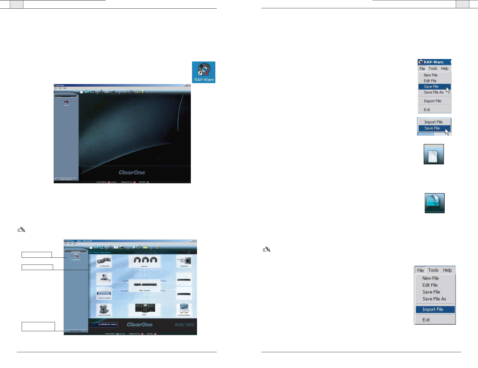
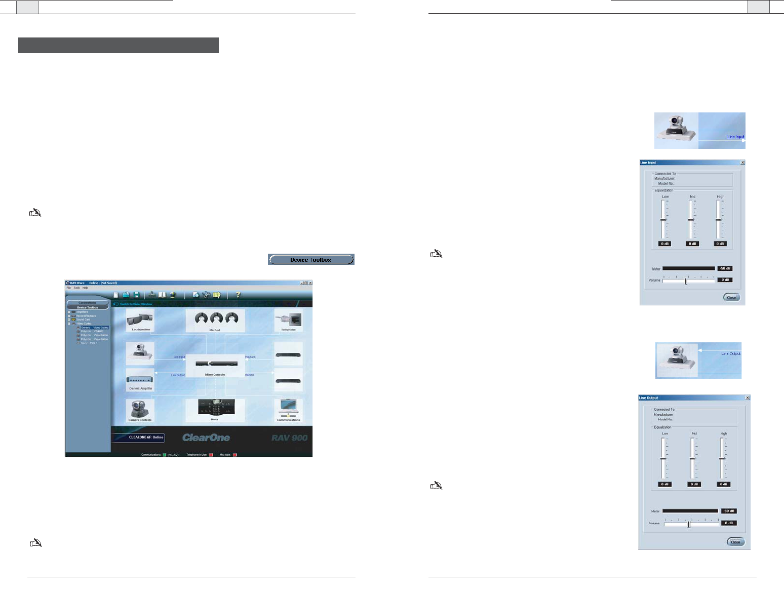
Menus and Toolbar: Easily create, open or save files, find RAV systems on the network, add
phonebook entries, configure regional settings and view the event log.
Connections: Lists available units connected through serial or USB ports, or on the network.
Device Toolbox: Lists common brands of auxiliary audio products (video codecs, sound
cards, VCRs and amplifiers). The audio settings for these devices have been optimized for use
with the RAV system.
Configuration Screen: Quickly access the configuration windows for the RAV system by
clicking the icons.
Online/Offline indicator: Shows connection status of RAV-Ware(online/offline) and the name
of the connected unit.
Status Indicators: Status for Communications (green = online, red = offline), Telephone In
Use (red = not in use, green = in use) and Mic Mute (red = mute).
Getting started with RAV-Ware
Please ensure that you have administrative privileges before attempting to install RAV-Ware
on computers running Windows 2000 or later. You should also review the System
Requirements on page 9, to ensure software will run correctly and that you have all the
necessary network information.
Install RAV-Ware
1. Close all programs or applications running on your PC or laptop and insert the RAV-Ware
CD that shipped with your RAV system into the CD-ROM drive.
• If the Autorun feature is enabled on the PC, the CD will open automatically.
• If the Autorun window does not open, select Run from the Start menu.Type
<drive>:\\setup.exe where <drive> is the letter of the CD-ROM drive (e.g.,
D:\\setup.exe).
2. Follow the on-screen instructions.
Note:The Disk Cost button allows you to view
all available disk space.
Introduction
Figure 3.1. Installing RAV-Ware
Connections
Device Toolbox
Menus and Toolbar
Status Indicators
Configuration
Screen
Online/Offline
Figure 3.3. Installing RAV-Ware
Figure 3.2. Disk Cost
RAV-Ware — Introduction
29
RAV-Ware files
You can save current RAV-Ware files, create new files, edit existing files and import files
using the menus and toolbar icons. When connected to a RAV unit, any changes made to a
RAV-Ware file are updated immediately, but must be saved to remain permanent.
To save a file
1. From the File menu, select
Save File
.
2. Browse to the desired location and enter the name of the file.
3. Click
Save
.
Tip
:You can right click on the configuration window and select
Save
File
to save your file.You can also select
Save As
to rename and save
the file you are working on.
To create a new file
1. Click the
New File
toolbar icon.
2. Select either the RAV 600 or RAV 900 depending on your
system.This will open the Configuration Screen where you can set
user preferences for your RAV system.
3. Save the file.
To edit an existing file
1. Click the
Edit File
toolbar button.
2. Locate and select the file you want to edit.
3. Click Open.
4. Make desired changes to the file.
5. Save the file.
Note: The changes will only take effect after they have been
imported to a connected RAV system.
To import a file
1. Connect to a RAV unit.
2. From the File menu, select
Import
.
3. Choose your RAV file.
4. Click
Open
.The RAV unit will reboot and then update with all the
file changes.
Tip
: You can also right-click on the configuration window and select
Import to import a saved RAV file.
Technical Services Group ~ 1-800-283-5936 (USA) ~ 1-801-974-3760
RAV-Ware — Introduction
28
Technical Services Group ~ 1-800-283-5936 (USA) ~ 1-801-974-3760
RAV-Ware connections
When you connect to the RAV unit, RAV-Ware automatically finds all RAV units connected
serially or on the same subnetwork and lists them in the Connections pane.
To connect to the RAV
1 Double-click the RAV-Ware desktop icon. Or, select RAV-Ware from the Start
menu (start/programs/rav-ware/ravware.exe).
2 Click the RAV icon in the Connection pane.
• If you are connected serially, the RAV configuration window appears.
• If you are connected through the network, you will be prompted to enter a user name
and password.The default user name is
ClearOne
and the default password is
RAV
.
Note: To connect to a RAV unit on a different subnetwork, use Network Find. See page 26.
Connected RAV unit
Online indicator with
RAV unit name
Configuration Screen
Figure 3.4. RAV-Ware units
Figure 3.5. Configuration window
/
/
RAV-Ware — Configuring System Settings
31
RAV-Ware — Introduction
30
Network Find
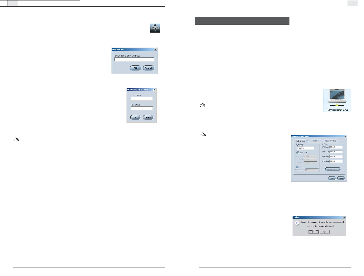
Network connection allows you to connect to any RAV system on your network
using its IP address or a unique network name. Use Network Find to access
RAV units not listed in the Connections pane, but which reside on the same network.
To open the Network Find
• Click the
Network Connection
button on the toolbar.
To connect to a system on the network
1. Enter the
IP address
or
name
of the RAV system to
which you want to connect.
2. Click
OK
.
3. You will see a password prompt window. Enter the
User Name
and
Password
of the networked system.
The default user name is
ClearOne
and the default
password is
RAV.
4. Click
OK
.The system icon will appear in the
Connection list and the Configuration screen will
open.
Note
: Once you have connected to a RAV unit using network find, a shortcut connection icon
for that unit will as long as RAV can find the unit on the network. If RAV can not find the unit,
the shortcut icon will be removed.
Technical Services Group ~ 1-800-283-5936 (USA) ~ 1-801-974-3760
System settings include Communication, Regional and Telephone settings.
Communication Settings
The Communication window allows you to adjust the connectivity settings of external devices
that communicate with the RAV, including the network, serial or USB connections. You can
connect a PTZ camera to the Camera port and use the Voice Tracking feature. You can also
change the RF frequency to match the frequency of your controller or if you are experiencing
interference on the current channel.
To open the Communication Settings window
• Click the
Communication
icon in the Configuration screen.
Note
: When RAV is connected to a DHCP network, network, IP, Gateway
and subnetwork addresses are automatically assigned. Unless you want to
specify a static IP address, there is no need to configure network settings.
To create a static IP address
Note: Contact the network administrator for net-
work settings.
1. Create a unique network name and enter it in the
Network Name
field. (Default is ClearOne-XX
where XX is the last two digits of the MAC
address.)
2. C
lear the Use DHCP option and enter the IP,
Subnet and Gateway addresses.
3. Select
Use DNS
if you have a Domain Name
Server and want name resolution (to use a net-
work name) for your static IP address.
4. In the IP Filters section, enter specific IP address-
es that will be allowed to access the RAV system.
You can specify a range of IP addresses by using
zeros. For example, entering 192.168.105.0 will
allow any IP addresses in the 192.168.105.1 to
192.168.105.254 range to access the RAV sys-
tem.
5. Click
OK
.
6. Click
Ye s
to save your settings.
Technical Services Group ~ 1-800-283-5936 (USA) ~ 1-801-974-3760
Figure 3.8. Network settings
Configuring System Settings
Figure 3.6. Network Find
Figure 3.7. User Name/Password
Figure 3.9. Confirm changes
RAV-Ware — Configuring System Settings
RAV-Ware — Configuring System Settings
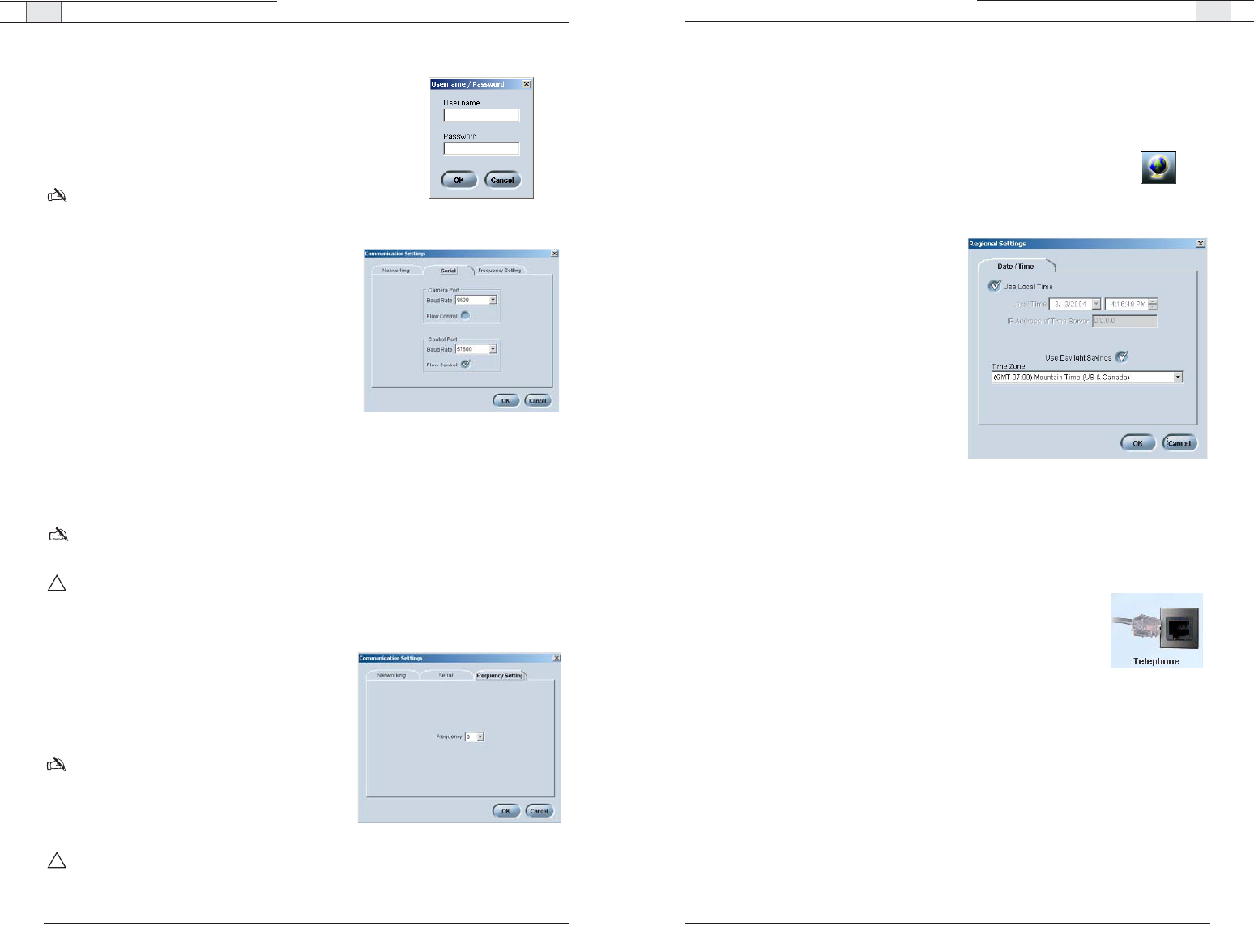
Regional Settings
In the Regional Settings window, you can configure the date and time to ensure an accurate
time stamp on log files.
To open Regional Settings
• Click the
Regional Settings
icon in the Configuration screen.
To set date and time
1. Select
Use Local Time
, if you want to use
the time on your local computer.
– Or –
Clear the
Use Local Time
check box and
enter the
IP address
for the time server.
2. Select
Use Daylight Savings
if your region
observes daylight savings time.
3. Select your
Time Zone
and click
OK
to save
settings.
Telephone Settings
In the Telephone Settings window you can set telephone preferences such as auto-answer,
auto-disconnect, ringer melody and program the local number. You can also adjust the telco
level control, country setting and the flash settings.
To open Telephone Settings
• Click the
Telephone Settings
button on the configuration screen.
Figure 3.13. Date/Time settings
33
Technical Services Group ~ 1-800-283-5936 (USA) ~ 1-801-974-3760
To change the User Name and Password
1. Click
User/Password
.
2. Specify the
User Name
.
3. Enter the
Password
.
4. Click
OK
.
Note
: This option is only available when you are connected
to a RAV unit.
To configure the Camera port
1. Set the
Baud Rate
to match the baud rate
indicated in the camera specifications.
2. Select
Flow Control
to enable hardware flow con-
trol.
3. Click
OK
to save settings and close the window.
To configure the Control port
1. Set the Control Port
Baud Rate
to match the baud
rate of the PC COM port or the control device.
2. Select
Flow Control
to enable hardware flow
control. (Flow Control is selected as default.)
3. Click
OK
to save settings and close the window.
Note: Flow Control is the regulation of information between two devices that are connected to
one another. ClearOne recommends enabling Flow Control on the RAV system.
Attention
: If you are connected to the RAV unit through the serial port, you will need to reboot
the unit before the baud rate and flow control changes take place. If you are connected to the
RAV unit through the USB port, changes are made instantly.
To change RF frequency channel
1. Click the
Frequency Setting
tab in the Regional
Settings window.
2. Select a new frequency. The new frequency will be
displayed.
Note
: The channel frequency allows the mixer to
communicate with the controller. The frequency used
by RAV-Ware must match the frequency used by the
controller. See page 54 to set the controller
frequency.
Attention
: If you are using the RAV 900, frequency
1 and frequency 8 are the same frequency.
Figure 3.11. Serial settings
32
Technical Services Group ~ 1-800-283-5936 (USA) ~ 1-801-974-3760
Figure 3.10. Password
Figure 3.12. Frequency settings
!
!
RAV-Ware — Configuring System Settings RAV-Ware — Customizing RAV Components
35
Technical Services Group ~ 1-800-283-5936 (USA) ~ 1-801-974-3760
34
Technical Services Group ~ 1-800-283-5936 (USA) ~ 1-801-974-3760
Your RAV system is pre-configured for optimal audio quality right out of the box. However,
you can customize the audio and adjust volume to match user preferences. You can also
change the mix of audio being sent to the far-end conference site and recording devices.
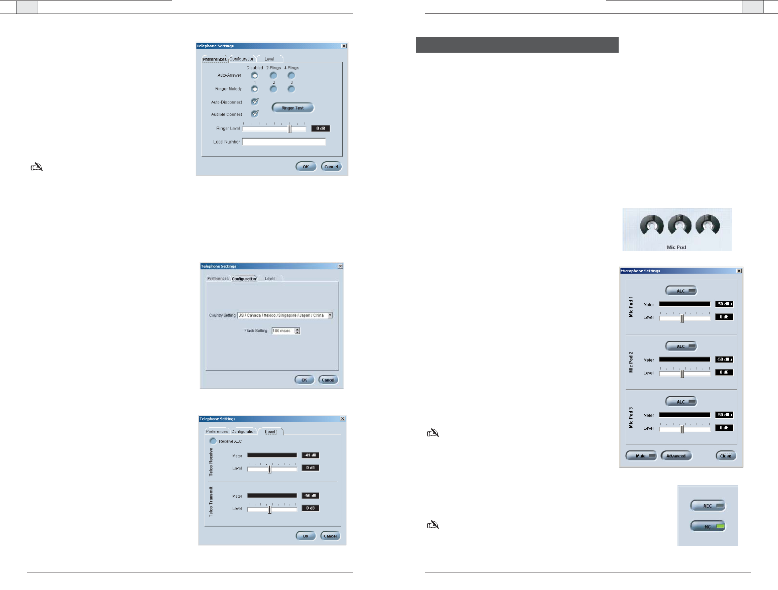
Microphones
You can adjust microphone volume and enable or disable Automatic Level Control (ALC)
settings in the Microphone Settings window. Automatic Level Control automatically adjusts
microphone levels to ensure participants’ voices are transmitted at consistent levels
regardless of whether people are speaking loudly or softly.
To access Microphone Settings
• Click the Mic Pod button on the configuration
window.
To enable ALC
• Click the ALC button.The indicator will turn green
when ALC is enabled.
To adjust audio level (volume)
• Using the slider, adjust the volume.The meter will
display output levels.
To set Acoustic Echo Cancellation (AEC)
1. Click
Advanced
.
2. Click
AEC
to enable Acoustic Echo Cancellation.
The indicator will turn green.
Note: AEC prevents echo from reaching the far-end.
ClearOne recommends keeping AEC enabled.
To set Noise Cancellation (NC)
1. Click
Advanced
.
2. Click
NC
to enable noise cancellation. The indicator will
turn green
Note: Noise Cancellation prevents ambient or background
noise from being sent to the far-end. ClearOne
recommends keeping NC enabled.
Customizing RAV Components
Figure 3.17. Microphone settings
To change telephone preferences
1. Set the system to
Auto-Answer
after
2
Rings
or
4 Rings
or select
Disabled
if you
want to manually answer calls.
2. Select
Auto-Disconnect
if you would like
RAV to disconnect when it detects loop-
drop or call progress tones.
3. Select from three available ringer melodies.
Click
Ringer Test
to hear selected melody.
Note
: This option is only available when you
are connected to a RAV unit.
4. Select
Audible Connect
if you would like
one tone to sound when the RAV is taken
off hook and two tones to sound when the
RAV is hung up.
5. Adjust ringer volume using the Ringer
Level slider.
6. Enter the
Local Number
for the RAV
system. The local number displays on the
third line of the controller LCD.
To select telephone configuration
1. Select the
Country
where the phone is
being used (default is US/Canada).
2. Select
Flash
duration from the Flash
Settings list. This setting is dependent on
the requirements of your PBX or
telephone system.
To adjust telephone level
1. Select
Auto Receive Level Control
.(The
default is Off.) Clearone recommends
keeping Auto Receive Level Control select-
ed.This feature automatically adjusts the
far end audio to keep it at a constant level.
2. Use the sliders to adjust the level of the
telco transmit and telco receive.
Figure 3.14. Telephone preferences
Figure 3.15. Telephone configuration
Figure 3.16. Telephone level Figure 3.18. Advanced settings
RAV 600/900 — Customizing RAV Components
RAV 600/900 — Customizing RAV Components
37
Technical Services Group ~ 1-800-283-5936 (USA) ~ 1-801-974-3760
36
Technical Services Group ~ 1-800-283-5936 (USA) ~ 1-801-974-3760
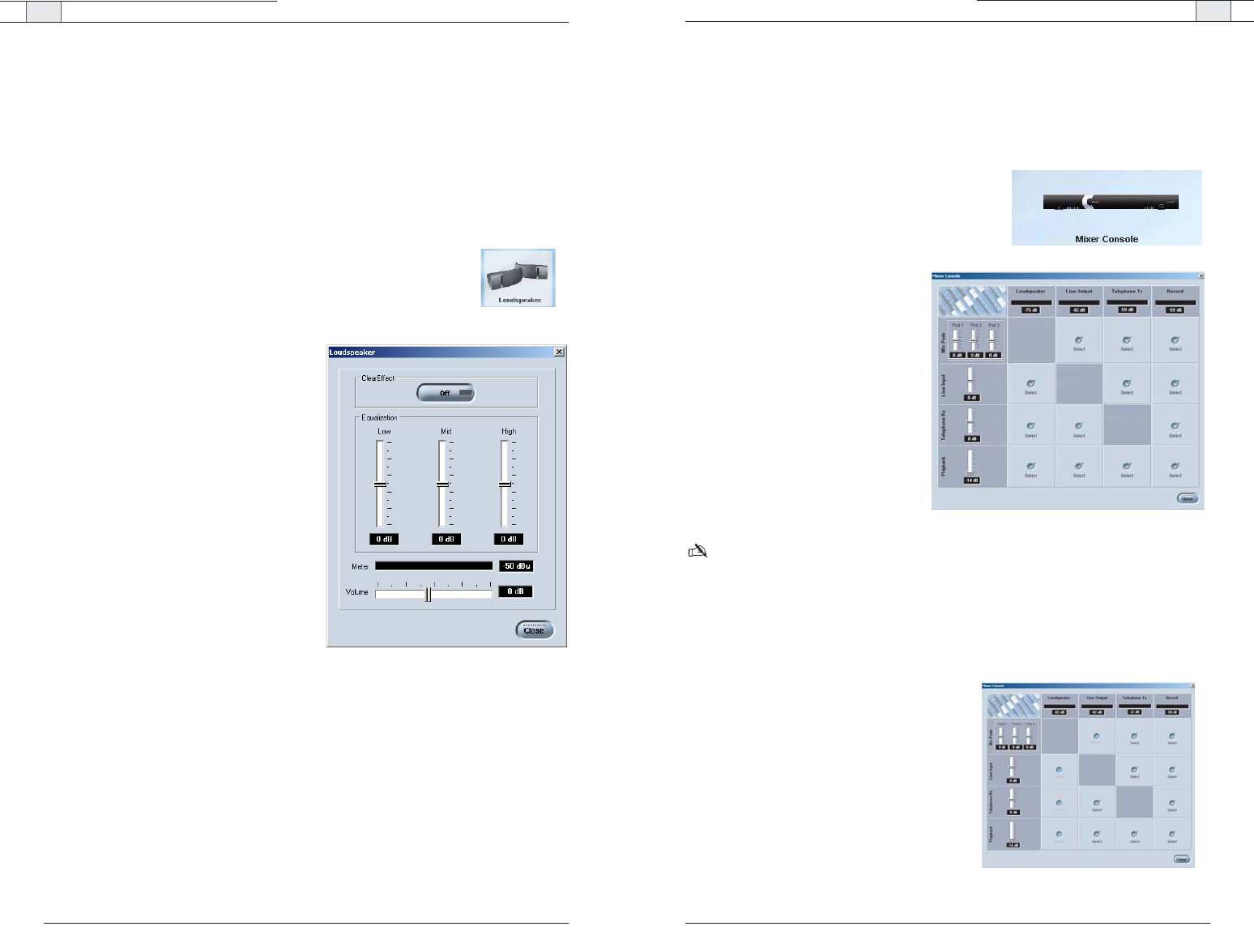
Mixer
The Mixer Console allows you to create audio mixes for the different outputs, adjust volume
levels and view the output meters. The audio inputs are shown along the left side of the win-
dow and the audio outputs are along the top.
To open the Mixer Console
• Click the
Mixer Console
button.
To create a mix of audio
• Select which audio is to be included in
each output mix. A check mark indi-
cates the audio will be included in the
output mix.
RAV-Ware does not give options to route
microphone audio to the loudspeakers,
the line input to the line output or the
telephone receive to the telephone
transmit. This prevents audio looping.
To adjust audio levels
• Use the sliders to adjust the audio lev-
els for Playback, Telephone, Line In
and the microphone pods.
Note: You can also adjust levels by opening the configuration windows for each component.
Changes made to the levels on the audio mixer window will be reflected in the configuration
windows.
Effects of using an external amplifier
If you connect an external amplifier to the RAV unit on either the Line Out port or the
Record Out port, the mixer console options change.
• If you place an external amplifier on the Line
Output, the options to route any audio to the
loudspeakers and to route the microphones to
the Line Output are no longer available.
• If you place an external amplifier on Record,
the options to route any audio to the loud-
speakers and to route the microphones to the
Record output are no longer available.
Figure 3.20. Audio Mixer
Loudspeakers
You can adjust your Bose loudspeaker equalization, change volume levels and enable
ClearEffect in the Loudspeaker Settings window. Equalization in RAV-Ware is similar to the
bass and treble adjustments on a stereo. Increasing or decreasing the low, mid and high
frequencies and levels allows you to customize loudspeaker audio and provide the optimal
listening experience for your users. When ClearEffect is enabled, it causes the audio coming
from the telephone line to emulate wideband audio. It does this by adding high and low
frequencies to the audio signal, creating a fuller sound.
To access Loudspeaker Settings
• Click the
Loudspeaker
button on the configuration window.
To enable ClearEffect
• Click the
ClearEffect Off/On
button. The
indicator will turn green when ClearEffect is
enabled.
To adjust equalization
• Adjust the the Low, Mid and High frequency
tones using the Equalization sliders.
To adjust audio level (volume)
• Using the slider, adjust the volume.
The meter will display output levels.
Figure 3.19. Loudspeaker settings
Figure 3.21. Audio Mixer with external amplifier
RAV-Ware — Configuring Auxiliary Devices RAV-Ware — Configuring Auxiliary Devices
39
Technical Services Group ~ 1-800-283-5936 (USA) ~ 1-801-974-3760
38
Technical Services Group ~ 1-800-283-5936 (USA) ~ 1-801-974-3760
Adjusting Line Input/Output settings
If your device is not listed in the Device Toolbox you can manually customize and configure
the audio of your auxiliary devices in the Line Input and Line Output windows. Line input
and output devices include video codecs, CD players, amplifiers and sound cards.
To access line input settings
• Open the Line Input window by clicking on
the
Line Input
device icon.
To adjust equalization
• Adjust the Low, Mid and High frequency
tones using the Equalization sliders.
To adjust audio level (volume)
• Using the slider, adjust the volume.The meter
will display input levels.
Note:To save the name and setting of your line
input device, refer to the Device Toolbox Editor
on page 43.
To access line output settings
• Open the Line Output window by clicking
on the
Line Output
device icon.
To adjust equalization
• Adjust the Low, Mid and High frequency
tones using the Equalization sliders.
To adjust audio level (volume)
• Using the slider, adjust the volume.The meter
will display input levels.
Note:To save the name and setting of your line
output device, refer to the Device Toolbox
Editor on page 49.
Figure 3.23. Line Input
Figure 3.24. Line Output
The RAV mixer has jacks for Line Input and Line Output that allow you to connect different
auxiliary devices . You can configure audio levels for these devices through RAV-Ware. You
can use devices that have preconfigured audio settings from the Device Toolbox or you can
manually set the audio settings for your line in and line out devices.
Preconfigured video codecs, amplifiers and sound cards
The audio settings for many common auxiliary devices such as video codecs, VCRs, amplifiers
and sound cards, have been pre-configured for optimal performance with the RAV system.
Preconfigured devices are listed in the Device Toolbox and can be placed on the Line In and
Line Out icons.
Note: If you would like to add a device to the Device Toolbox, please refer to the Device Toolbox
Editor on page 43.
To select a pre-configured line-level device
1. Click the
Device Toolbox
button to display preconfigured devices.
2. Click the +to expand the category that matches your device type.
3. Click the device name, hold and drag it to the configuration screen. Drop over the Line
Input or Output. The label and icon will change based on the selected device.
Note
: Video codecs will cover both Line Input and Output. A sound card should be placed on
Line Input or on both input and output for web conferencing. An amplifier is Line Output only.
Line Input and Output
Figure 3.22. Line input device list
RAV-Ware — Configuring Auxiliary Devices RAV-Ware — Configuring Auxiliary Devices
41
Technical Services Group ~ 1-800-283-5936 (USA) ~ 1-801-974-3760
40
Technical Services Group ~ 1-800-283-5936 (USA) ~ 1-801-974-3760
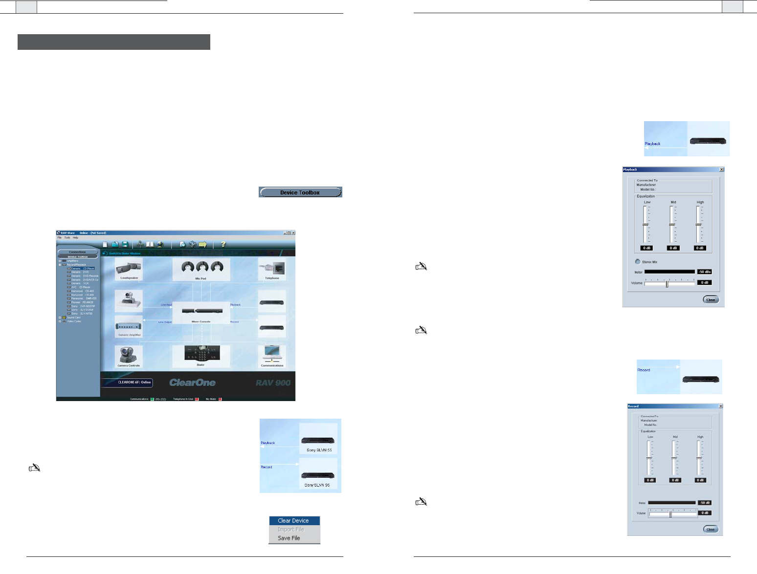
Adjusting Record/Playback settings
If your device is not listed in the Device Toolbox you can manually customize and configure
the audio of your auxiliary devices.The Record Settings window is used to customize and
configure audio being sent to recording devices that are connected to the record jack on the
RAV mixer. The Playback Settings window is used to customize and configure the audio from
the playback device that is connected to the Playback jack on the RAV mixer.
To open playback settings
• Open the Playback configuration window by clicking
on the
Playback
device icon.
To adjust equalization
• Adjust the Low, Mid and High frequency tones using
the Equalization sliders.
To enable Stereo Mix
• Select
Stereo Mix
if your playback device uses stereo
inputs.
Note: RAV provides mono-only audio.
To adjust audio level (volume)
• Using the slider, adjust the volume.The meter will dis-
play input levels.
Note
:To save the name and setting of your playback device, refer to the Device Toolbox Editor
on page 43.
To open record settings
• Open the Record configuration window by clicking on
the Record device icon.
To adjust equalization
• Adjust the Low, Mid and High frequency tones using
the Equalization sliders.
To adjust audio level (volume)
• Using the slider, adjust the volume.The meter will dis-
play input levels.
Note: To save the name and setting of your recording
device, refer to the Device Toolbox Editor on page 49.
Figure 3.26. Playback
Figure 3.27. Record
Record and Playback devices include VCRs, DVD players and sound cards, however the
Record/Playback jacks are line level inputs and outputs and are not restricted to these
devices. You can use devices that have preconfigured audio settings from the Device Toolbox
or you can manually set the audio settings for your VCRs or DVD players.
Preconfigured record/playback devices
The audio settings for many common record/playback devices have been pre-configured for
optimal performance with the RAV system. Preconfigured devices are listed in the Device
Toolbox and can be placed on the Record and Playback icons.
To select a preconfigured record/playback device
1. Click the
Device Toolbox
button to display preconfigured devices.
2. Expand the category that matches the device you added.
3. Click the device and drag it to the configuration screen. Drop
over the Record or Playback icon. The label and icon will
change based on the selected device.
Note
:You are not limited to record and playback devices
with these connectors. The Record and Playback jacks are
line input and line output jacks and can be connected to
video codecs, CD players and amplifiers.
To remove a device
1. Right-click on the device you want to remove.
2. Select
Clear Device
.
Figure 3.25. Record/Playback device list
Record and Playback
RAV-Ware — Configuring Auxiliary Devices RAV-Ware — Dialer and Phonebook Usage
43
Technical Services Group ~ 1-800-283-5936 (USA) ~ 1-801-974-3760
42
Technical Services Group ~ 1-800-283-5936 (USA) ~ 1-801-974-3760
To test camera presets
1. Select the camera you are testing.
2. Click
Run Preset
for each microphone pod to test the programming.
The camera should move to the preset position for each microphone.
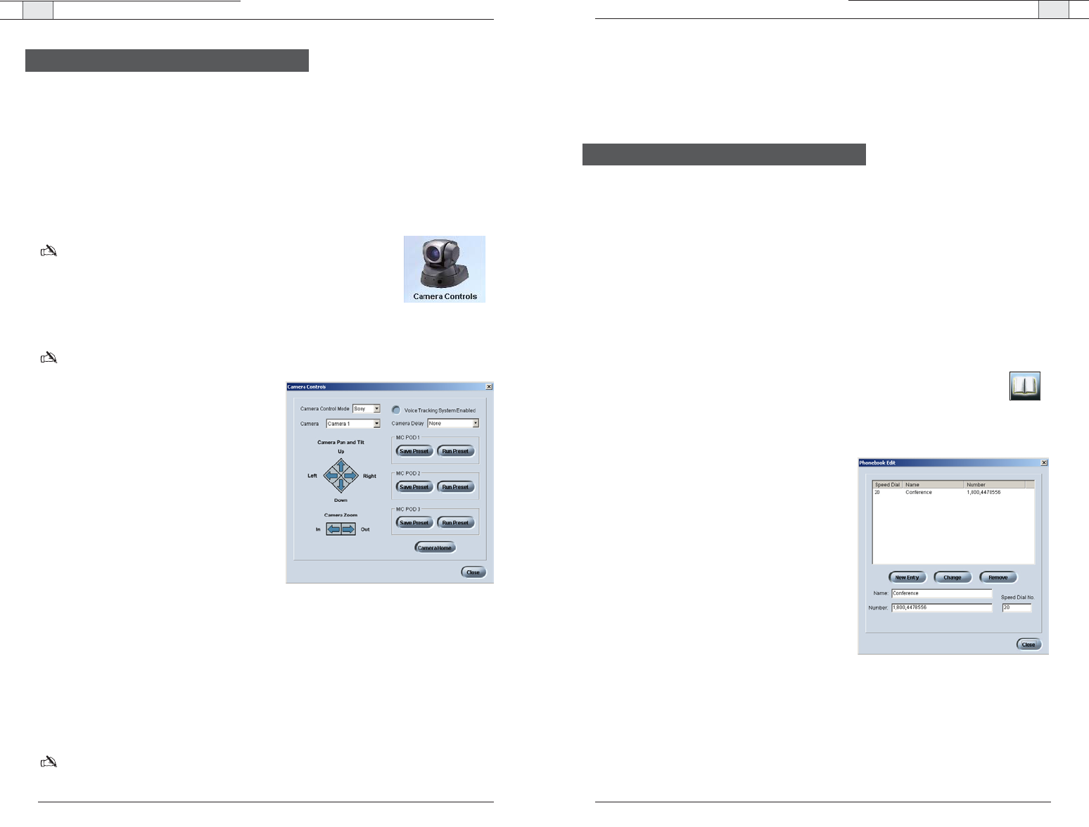
The RAV system includes a Phonebook that stores up to 20 names and phone numbers.
Phonebook entries may be entered through RAV-Ware or using the RF controller.The Dialer in
RAV-Ware mimics the RF controller and may be used to make calls, mute microphones and
adjust the loudspeaker volume. See pages 48-55 for information on using the RF controller.
Phonebook
RAV-Ware features a Phonebook utility which stores up to 20 phone numbers.These
numbers are also assigned a speed dial number for dialing convenience through the RAV
Controller. Phonebook entries are listed in alphabetical order. You can add, edit or delete
entries from the Phonebook window.
To open the Phonebook
• Click the
Phonebook
button on the toolbar.
To add a Phonebook entry
1. Click
New Entry
.
2. Enter the
Name and Number
.
3. Enter a
Speed Dial Number
.
4. Click
Add Entry
.
To delete a Phonebook entry
1. Select the entry you want to delete.
2. Click
Remove
.
To edit a Phonebook entry
1. Select the entry you want to edit.
2. Make desired changes to the entry.
3. Click
Change
.
Dialer and Phonebook Usage
Figure 3.29. Phonebook Edit
The RAV system provides voice tracking capabilities through VISCA control port connection
to a PTZ camera.
Setting camera presets
The camera presets are programmed in RAV-Ware and assigned to each microphone pod.
When a specific microphone is activated, the PTZ camera will move to the associated preset
camera position.The RAV 900 Supports three camera positions and a home position. The
RAV 600 supports two camera positions and a home position.
Note: The PTZ camera can still be controlled manually from the
camera or video codec remote control.
To open Camera Controls
• Click the
Camera Controls
button on the configuration window.
Note
: This option is only available when you are connected to a RAV unit and have a camera
connected to the VISCA port.
To set camera presets
1. Select the
Camera Control Mode
, either Sony
or Canon.
2. Select which camera you are programming.
3. Select the
Camera Delay
.
Camera delay is the amount of time the
microphone must be activated before the
camera moves to the preset position and
amount of time the microphone must be
inactive before returning to the home position.
ClearOne recommends setting the camera
delay to at least two seconds to prevent the
camera from changing positions at every
sound.
4. Using the directional arrow buttons and the Zoom In and Out buttons, position the camera
for the first microphone pod.
5. Click
Save Preset
under the microphone pod to assign the camera position to the mic pod.
6. Repeat steps for the second and third mic pod (RAV 900 only) and home position.
7. Select the
Voice Tracking System Enabled
.
Note
: Once you set the presets, do not switch Camera Control Mode (the camera type).This will
delete all presets.
Figure 3.28. Camera Controls
Camera Controls
RAV-Ware — Phonebook and Dialer Usage
RAV-Ware— Phonebook and Dialer Usage
45
Technical Services Group ~ 1-800-283-5936 (USA) ~ 1-801-974-3760
44
Technical Services Group ~ 1-800-283-5936 (USA) ~ 1-801-974-3760
To make a call from the phonebook
1. Using the mouse, select the number in the phonebook. The name and number appear in the
display window.
2. Click
ON/OFF
button to dial the call.
Tip
: You can also double click the name in the phonebook. The phone will be taken off hook and
the number dialed.
To end a call
• Click the
ON/OFF
button.
To redial
• Click the
REDIAL
button. The phone will automatically be taken off hook and the last
dialed number will be called.
To send a Flash signal
• If your telephone service includes call transfer, call waiting or conference calling, you can
use the Flash key. Refer to your local telephone service provider for details.
To mute/unmute
1. Click the
MUTE
button to mute all microphones.The LED on the microphones will
illuminate red.
2. Click the
MUTE
button again to unmute all the microphones. The LED on the microphones
will illuminate green.
To adjust call volume
• Use the
UP
and
DOWN
buttons to adjust the call volume to the desired level.
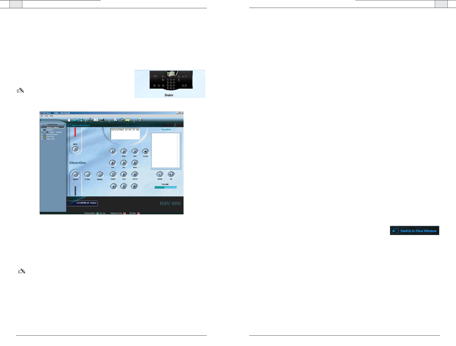
To return to the Configuration screen
• Click the
Switch to Flow Window
to return to the configuration
screen.
Dialer
While most calls will be made using the RF controller, you can also manage all your calls
from the Dialer in RAV-Ware. You can dial a number, redial the last dialed call, and
disconnect calls. You can also use flash settings, mute the microphones and adjust
loudspeaker volume.
To open the Dialer
• Click the
Dialer
icon on the configuration window.
Note
: This option is only available when you are
connected to a RAV unit and have a telephone line
connected to the LINE port on the mixer.
To make a call
1. Click the
ON/OFF
button.
2. Dial the number as you would on a standard phone. The number appears in the dialing
window at the top.
Note: You can also pre-dial the number and press the
ON/OFF
button to connect the call. Press
and hold the pound key (#) to enter a pause in the dialing string.
Tip
: You can also dial using the 0-9, * and # on your on your keyboard.The Enter key connects
to and disconnects from the telephone line.
Figure 3.30. Dialer window
/
RAV-Ware — Advanced Features RAV-Ware — Advanced Features
47
Technical Services Group ~ 1-800-283-5936 (USA) ~ 1-801-974-3760
46
Technical Services Group ~ 1-800-283-5936 (USA) ~ 1-801-974-3760
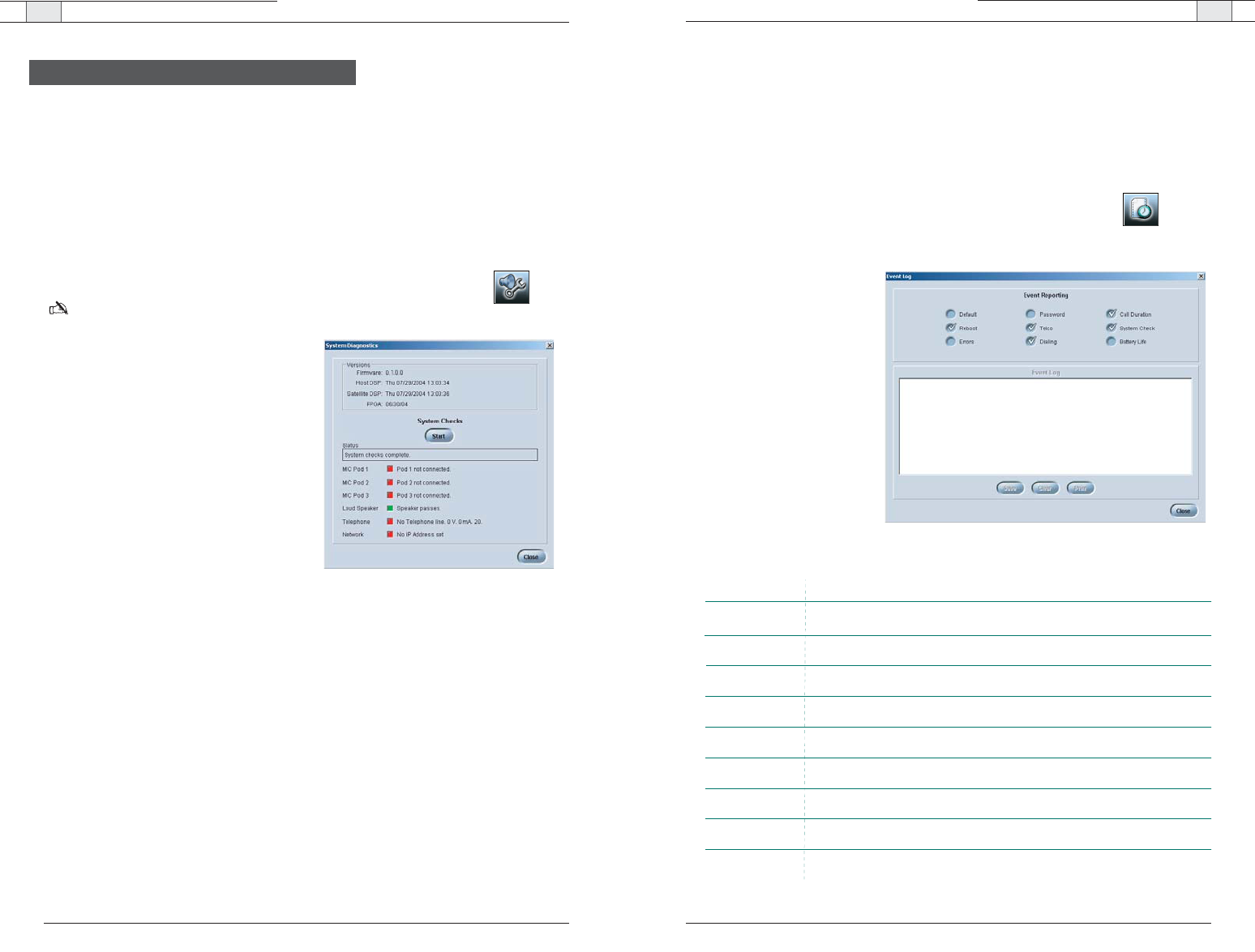
Event Log
The Event Log keeps record of a user selectable list of events. You select which events you
want recorded and RAV-Ware keeps a log allowing you to periodically review events and
make sure the system is running smoothly. You can also save the Event Log as a .txt file.
Check the Event Log when there are communication errors or for other troubleshooting.
To open the Event Log
• Click the
Event Log
toolbar button.
To track events
• Select the events you would
like to log.
To save an Event Log
1. Click the
Save
button.
2. Name the file.
3. Click
Save
.
The log is saved as a .txt file.
To print an Event Log
1. Click the
Print
button.
2. Select the printer.
3. Click
Print
.
Figure 3.32. Event Log
The Advanced features of RAV-Ware allow you to perform system diagnostics and
administrative functions.
System Checks
The System Diagnostics window allows you to check your RAV system to be sure all
components of your system are connected and working properly.
To open the System Checks
• Click the
System Diagnostics
toolbar button.
Note
: This option is only available when you are connected to a RAV unit.
To run System Checks
• Click the
Start
button.
If you are local (in the same room as the
loudspeakers), you will hear a tone as the
RAV checks all components. When the
check is complete, lights will indicate the
status of each component. Green indicates
the component is connected and function-
ing. Red indicates a problem with the com-
ponent.
Advanced Features
Figure 3.31. System Checks
Function
Logs when telco was enabled and disabled.
Selection
Logs internal errors. The same errors are displayed in the Error Log.
Logs how long each call lasts.
Logs every time the RAV system reboots.
Logs when system checks are performed and the results of the checks.
Logs battery level as reported by the RF controller.
Logs dialed numbers.
Default
Reboot
Errors
Password
Telco
Dialing
Call Duration
System Check
Battery Life
Logs when the mixer settings are defaulted.
Logs failed and successful access through TCP/IP or web interface
RAV-Ware — Advanced Features
RAV-Ware — Advanced Features
49
Technical Services Group ~ 1-800-283-5936 (USA) ~ 1-801-974-3760
48
Technical Services Group ~ 1-800-283-5936 (USA) ~ 1-801-974-3760
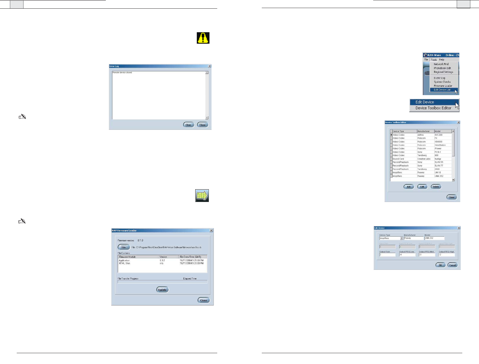
Device Toolbox Editor
The Device Toolbox Editor allows you to add your auxiliary devices to RAV-Ware. You can
add video codecs, sound cards, record/playback devices and amplifiers to customize your sys-
tem and easily access these devices for future RAV installations.
To open the Device Toolbox Editor
• From the Tools menu, select
Edit Device
list
-Or-
Right-click on the Device Toolbox pane and click
Device Toolbox
Editor
.
To add a device
1. Click
Add
.
2. Select the
Device Type
from the Device Type
list.
3. Enter the
Name
of the Manufacturer.
4. Enter the
Model Number
of the device.
5. Enter the
Equalization
levels and the
Gain
settings.
6. Click
OK.
The new device will appear in the
Toolbox Editor window and in the Device
Toolbox.
To edit a device
1. In the Device Toolbox Editor, select the device
you want to modify.
2. Click
Edit
.
3. Change any information.
4. Click
OK
.
Tip: You can also double click the device in the
Device Toolbox pane to edit.
To delete a device
1. In the device list, click the device you want to delete.
2. Click
Delete
.
3. Confirm that you want to delete the device.
Figure 3.35. Toolbox Editor
Figure 3.36. Edit device
Error Messages
Whenever the RAV system encounters an error, an error icon will appear in the
lower left corner of the screen. Review this log to troubleshoot problems.
To view error messages
• Double click the
Error
icon in the
lower left corner of the RAV win-
dow.
To clear error messages
•Click
Clear
.
Note: Errors can be tracked using
the Event Log.
Firmware upgrades
Firmware upgrades are included with any updated RAV-Ware release. Once the RAV-Ware
update has been installed, you should upgrade the firmware. Firmware can be upgraded
through the network, serial or USB connection.
To open the RAV Firmware Loader
• Click the
Firmware Loader
icon on the toolbar.
Note
: This option is only available
when you are connected to a RAV
unit.
To upgrade RAV firmware
1. Click
File.
2. Browse to the correct folder located
in RAV-Ware firmware.
3. Click
Open
.
4. Click the
Update
button.
The File Transfer Progress bar will
indicate when the firmware has
been uploaded.
Figure 3.34. Firmware upgrades
Figure 3.33. Error log
/

Using the RAV 4
Using the RAV — Using the Controller
53
Technical Services Group ~ 1-800-283-5936 (USA) ~ 1-801-974-3760
Using the RAV — Using the Controller
52
Technical Services Group ~ 1-800-283-5936 (USA) ~ 1-801-974-3760
Managing Calls
Most phone specific functions, such as dialing a call or adding a phonebook entry, will be
managed from the controller. Phonebook and dialer actions can be done through Rav-Ware
as well. See page 39 for more information.
Using the Controller
To answer a call
• Press on the controller to answer the
call. When there is an incoming call, the
phone rings and the LEDs on the micro-
phones flash.
Note: RAV can also be set to Auto-Answer.
See page 53 to enable Auto-Answer.
To make a call
1. Press . You will hear a dial tone.
2. Dial the number as you would on a
standard phone. The number appears on
the LCD screen.
Note
: The LCD has an entry maximum of
44 characters
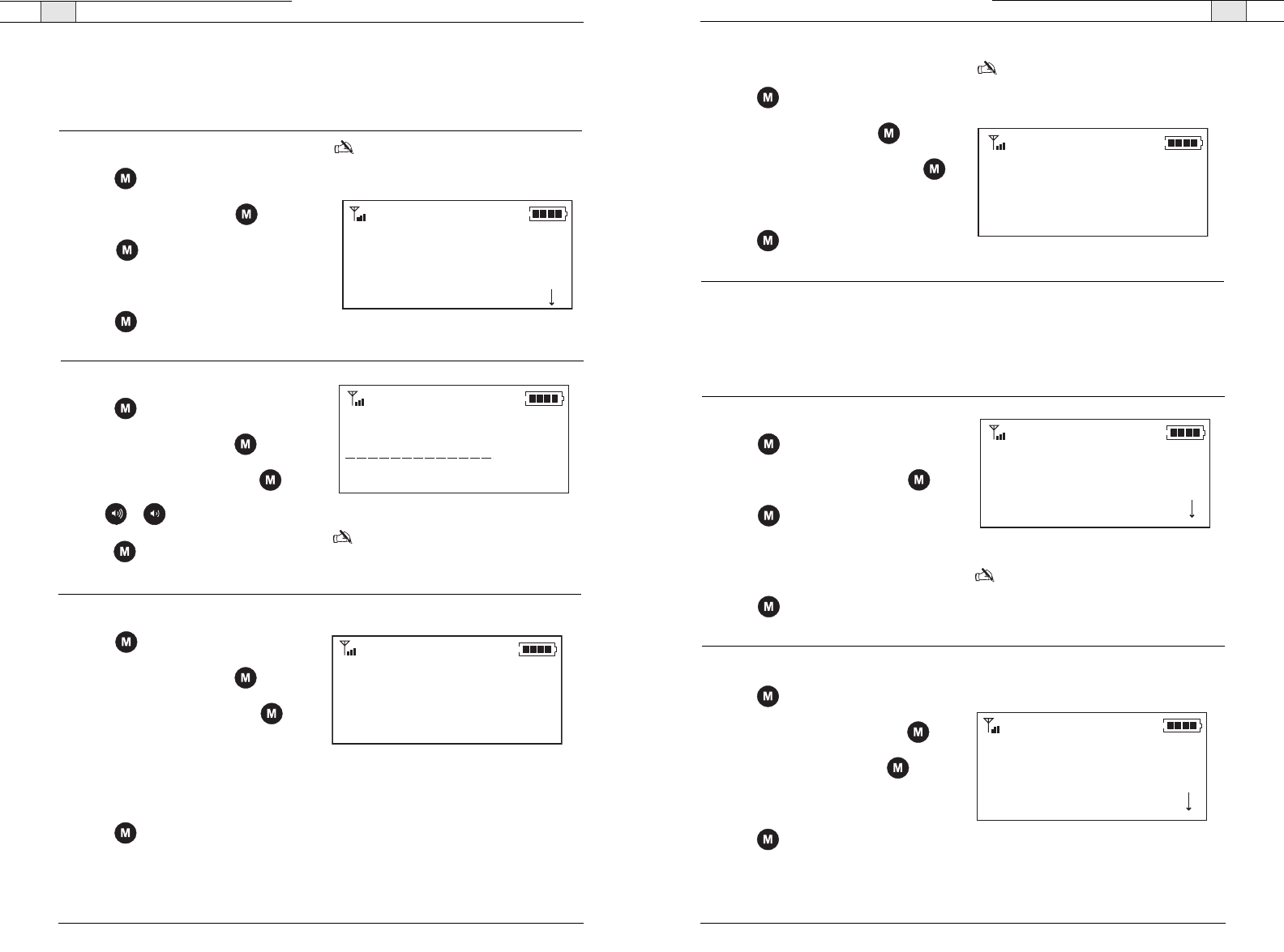
18005781234
Figure 4.1. Dialing window
To pre-dial a call
1. Dial a phone number.
You can press to delete the last digit
entered in the pre-dialing string.
2. Press to send the call.
Note
: The phonebook key will delete the
entire dial string if you press it for two
seconds. Pressing and holding the pound
(#) key for 2 seconds will insert a pause
into the dialing string.The duration of the
pause is two seconds.
To use speed dial
• Press and hold the assigned speed dial
number on the dial pad.
Note
:You can dial numbers 1-9 by pressing and
holding the assigned number. To dial speed dial
10, press and hold 0.
To redial a phone number
• Press .
Note
:REDIAL saves the last number that
was dialed. Once REDIAL is pressed, the
phone will be taken off hook and the
number will be dialed.
To dial a call from the Phonebook
1. Press on the controller.
2. Scroll to the entry and press .
3. Press to dial the number.
Conference
Sales Team
Product Management *
Figure 4.2. Dialing from the phonebook
To use the status key
• Press and hold for two seconds to
display the status of the RAV.
If the phone is not in use (on-hook) the
LCD will display the device name, the date
and time and the local number.
If the phone is in use (off-hook), the LCD
will display the call duration, the date and
time and the dialed number.
To send a flash signal
• Press to use call transfer, call waiting
or conference calling.
Note
: This setting is dependent on your
PBX service or local phone service. Refer
to your PBX vendor or local telephone
service for details.
To adjust the speaker volume
• Press to increase the volume.
– or –
• Press to decrease the volume.
To end a call
• Press to disconnect the call.
Note
: RAV can also be set to Auto-
Disconnect. See page 54 to enable Auto-
Disconnect.
To mute/unmute microphones
1. Press to mute the microphones. The
Microphone LEDS will light red.
2. Press again to unmute microphones.
The microphone LEDS will light green.
Note:This function mutes all microphones
in the room.The microphone LEDs and the
mixer front panel LEDs light red when the
microphones are muted.
ClearOne 55
10/13/04 4:33 PM
8013033583
11:14
10/13/04 4:33 PM
9795311468
Figure 4.3. On hook status
Figure 4.4. Off hook status
RAV — Programming Phone Preferences
55
Using the Phonebook from the controller
The Phonebook stores up to 20 names and numbers. You can add, edit and delete any of the
contacts.
Technical Services Group ~ 1-800-283-5936 (USA) ~ 1-801-974-3760
RAV — Programming Phone Preferences
54
You can manage the phonebook, adjust phone settings such as ring melody and tone and set
preferences such as country codes and language through the menu options outlined below.
You can also program these preferences in the RAV-Ware software. Refer to Chapter Three
for more information on RAV-Ware.
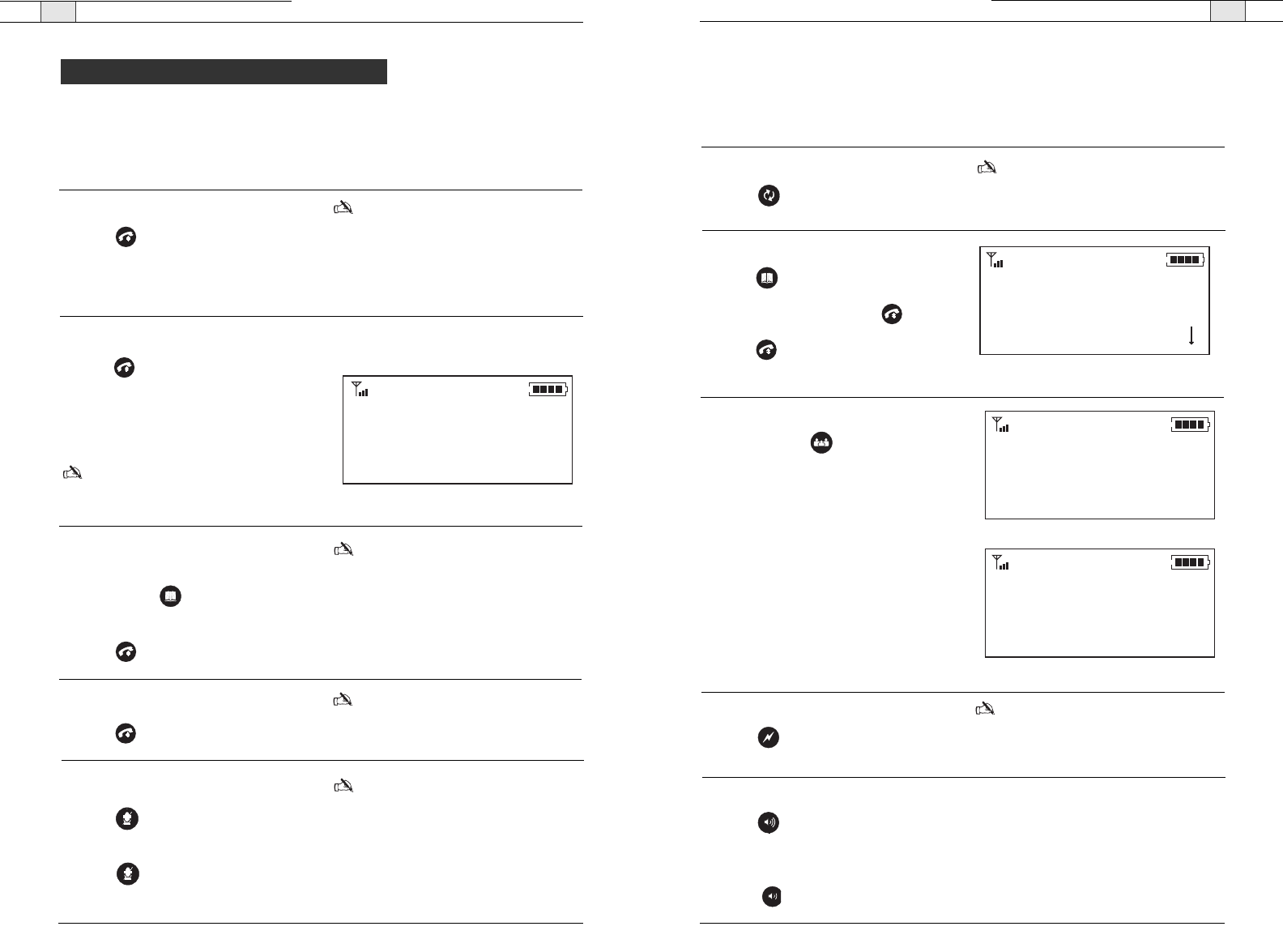
Accessing the menu
The main menu gives you three options: Phonebook, Settings and Configuration. An asterisk
indicates your position in the menus and a down arrow indicates that the menu
continues. Once in menu mode use the arrow keys to navigate. moves the cursor to the
right. is a backspace key. is a delete key or a back key that moves you to the previ-
ous screen. saves entries and moves the cursor to the next line.
To access the menu
• Press on the controller to access the
RAV program menu.
*
Technical Services Group ~ 1-800-283-5936 (USA) ~ 1-801-974-3760
Menu
Phonebook Settings Configuration
Delete
Edit
Add
Auto-Disconnect
Auto-Answer
Ringer Volume
Ring Melody
Select Language
Select Frequency
Flash Duration
Select Country
RF Radio Test
LCD Contrast
IP Address
Version
Programming Phone Preferences
Figure 4.5. Menu tree
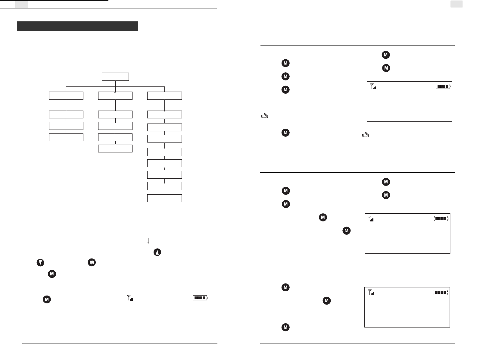
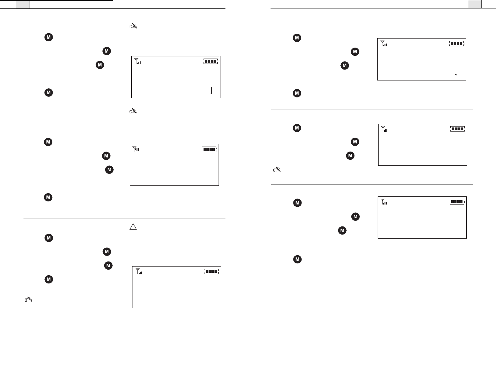
To add a Phonebook entry
1. Press to access the menu options.
2. Press to select Phonebook.
3. Press again to select Add.
4. Type the Name using the keypad.
Note
: Press a keypad key repeatedly to
cycle through its characters.
5. Press to advance to the Number
field.
6. Type the number using the keypad.
7. Press to advance to the Save option.
8. Press again to save the entry and
return to the Phonebook menu.
Note
: Entries added to the phonebook
through the controller are assigned speed
dial number 0. This means there is no
speed dial associated with this number.You
must use RAV-Ware to change this. See
page 39 for information.
Name
Number
Save
Figure 4.7 Adding a contact
To edit a Phonebook entry
1. Press to access the menu options.
2. Press to select Phonebook.
2. Scroll to Edit and press .
4. Scroll to a desired name and press .
3. Make changes to the name and number
using the keypad.
4. Press to advance to the Save option.
5. Press again to save the changes and
return to the Phonebook menu.
Sales Team
8886451234
Save
Figure 4.8. Editing a contact
To delete a Phonebook entry
1. Press to access the menu options.
2. Scroll to Delete and press .
3. Choose the entry you want to delete.
4. Press to delete the entry and return
to the Phonebook menu.
Add
Edit
Delete *
Figure 4.9. Deleting a contact
Phonebook
Settings
Configuration
*
Figure 4.6. Main Menu
RAV — Programming Phone Preferences
57
Technical Services Group ~ 1-800-283-5936 (USA) ~ 1-801-974-3760
RAV — Programming Phone Preferences
56
Technical Services Group ~ 1-800-283-5936 (USA) ~ 1-801-974-3760
Configuration
The configuration menu provides options for selecting countries, languages and RF
frequencies, as well as configuring the Flash setting.
Adjusting the Settings
You can activate the auto-answer setting, activate auto-disconnect, select ringer melodies
and adjust your ringer in the Settings menu.
To select a Ring Melody
1. Press to access the menu options.
2. Scroll to Settings and press .
3. Press again to select Ringer Melody.
4. Select one of the three ringer melodies.
5. Press to save the selection and return
to the Settings menu.
Note
: Once you select a melody, you will
hear it played through the speakers.
To adjust the Ringer Volume
1. Press to access the menu options.
2. Scroll to Settings and press .
3. Scroll to Ringer Level and press .
4. Use or to adjust the volume.
5. Press to save and return to the
Settings menu.
Note
: Ringer volume is indicated by a
horizontal bar on the LCD screen.
Ringer Melody
Ringer Level
Auto Answer
*
Figure 4.10. Ringer melody
Ringer Level
Figure 4.11. Ringer level
To activate Auto-Answer
1. Press to access the menu options.
2. Scroll to Settings and press .
3. Scroll to Auto Answer and press .
4. Select After 2 Rings or After 4 Rings
-Or-
Select Disable to deactivate the Auto
Answer function.
5. Press to save selection and return to
the Settings menu.
After 2 Rings
After 4 Rings
Disable
*
Figure 4.12. Auto answer
To activate Auto-Disconnect
1. Press to access the menu options.
2. Scroll to Settings and press .
3. Scroll to Auto Disconnect and press .
4. Select Enable or Disable.
5. Press to save selection and return to
the Settings menu.
Note: When enabled, Auto-Disconnect will
automatically hang up the phone once the
other end is disconnected.
Enable
Disable *
Figure 4.13. Auto disconnect
To select a Country
1. Press to access the menu options.
2. Scroll to Configuration and press .
3. Press again to select Country.
4. Select a country from the list of
available countries.
5. Press to save the country selection
and return to the Configuration menu.
Note: This assigned the telco for the
specific country settings.
USA/Canada
Europe
Australia
*
Figure 4.14. Select a country
To select a Language
1. Press to access the menu options.
2. Scroll to Configuration and press .
3. Scroll to Language and press .
4. Select a language from the list.
5. Press to save the language and
return to the Configuration menu.
English
Spanish
French *
Figure 4.15. Select a language
To check the RAV Version
1. Press to access the menu options.
2. Scroll to Configuration and press .
3. Scroll to Version and press .The
version of the RAV controller firmware
will display.
4. Press to exit and return to the
Configuration menu.
RAV — Programming Phone Preferences
59
To change LCD Contrast
1. Press to access the menu options.
2. Scroll to Configuration and press .
3. Scroll to Contrast and press .
4. Scroll to the contrast from 0–3.
5. Press to select the contrast and
return to the Configuration menu.
Technical Services Group ~ 1-800-283-5936 (USA) ~ 1-801-974-3760
RAV — Programming Phone Preferences
58
Technical Services Group ~ 1-800-283-5936 (USA) ~ 1-801-974-3760
Contrast 0
Contrast 2
Contrast 1 *
Figure 4.19 Contrast
To select a Frequency
1. Press to access the menu options.
2. Scroll to Configuration and press .
3. Scroll to Frequency and press .
4. Choose a frequency from 1–8.
5. Press to save the frequency and
return to the Configuration menu.
Note: The channel frequency allows the
mixer to communicate with the controller.
The frequency in RAV-Ware must match
the RAV controller frequency. See page
28.
Note
: When using the RAV 900, frequency
1 and frequency 8 are the same channel.
Frequency 1
Frequency 2 *
Frequency 3
Figure 4.16. Select a frequency
To enter Flash Duration
1. Press to access the menu options.
2. Scroll to Configuration and press .
3. Scroll to Flash Duration and press .
4. Type the duration number from 50–1000.
5. Press to save the duration and return
to the Configuration menu.
1000
Save
Figure 4.17. Enter flash settings
To perform RF Radio Test
1. Press to access the menu options.
2. Scroll to Configuration and press .
3. Scroll to RF Radio Test and press .
4. Press to exit and return to the
Configuration menu.
Note
: The RAV controller will send out a
radio signal and display the signal strength
between the controller and the mixer. Use
this feature to ensure the mixer and
controller are set to the same frequency
and to verify signal strength.
Attention
: If you are having trouble with
the communication between the controller
and the mixer, refer to the Troubleshooting
guide for tips on improve signal strength.
RF Radio Test
Exit
-------
Figure 4.18 RF Radio test
Version
Exit
1.0.0
Figure 4.21 Version
To view the IP address
1. Press to access the menu options.
2. Scroll to Configuration and press .
3. Scroll to IP Address and press .
Note:The IP address for the RAV unit will
display on the LCD
Figure 4.20 Contrast
IP Address
Exit
191.151.147.102
!

Web Interface 5
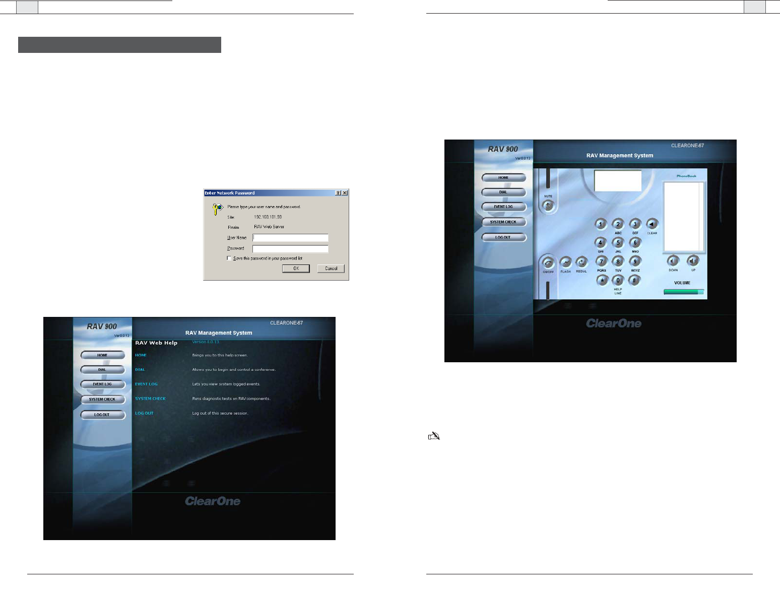
Web Interface — Overview
63
Dial
You can make all your calls from the Dialer in the web interface. You can dial a number,
redial the last dialed call, and disconnect calls. You can also use flash settings, mute the
microphones and adjust volume.
To open the dialer window
• Click the
Dial
button in the left channel navigation..
To make a call
1. Click the
ON/Off
button to take the phone off-hook.
2. Using the number pad, dial a phone number just as you would on a phone.
Note: You can also pre-dial the number and click the
ON/OFF
button to connect the call. Click
the pound button (#) to enter a pause in the dialing string.
Tip
: You can also dial using the 0-9, * and # on your on your keyboard. Enter connects to and
disconnects from the telephone line.
Technical Services Group ~ 1-800-283-5936 (USA) ~ 1-801-974-3760
Web Interface — Overview
62
Technical Services Group ~ 1-800-283-5936 (USA) ~ 1-801-974-3760
Accessing the web interface
The RAV has a built-in web server that provides a remote access interface to your RAV system.
However, not all programming and metering functions are available The web interface allows you
to connect to a RAV unit, run system checks, view the event log and manage calls.
To use the web interface from outside your network, your firewall must be properly configured to
allow access. If you are accessing RAV from within the network, you may use the network name.
The web interface uses port 80.
To connect to RAV through the web
interface
1. Open a web browser and enter the
IP
address
or
Network Name
of the RAV in the
address bar.
2. Enter your
User name
and
Password
.The
default user name is
ClearOne
and the
default password is
RAV
.
The RAV web interface opens. Navigation
buttons are shown in the left channel.
Overview
Figure 5.1 Network Password
Figure 5.2 RAV-Ware management system
Figure 5.3. Dialer window
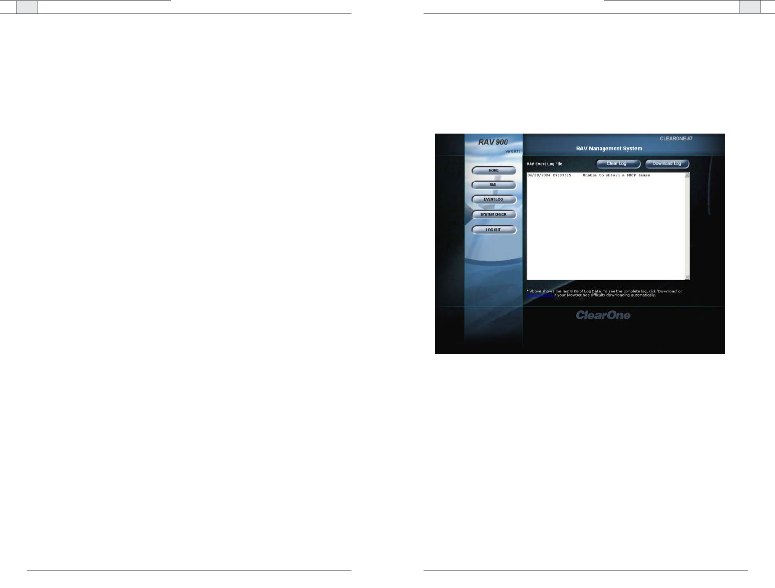
Web Interface — Overview
65
Technical Services Group ~ 1-800-283-5936 (USA) ~ 1-801-974-3760
Web Interface — Overview
64
To make a call from the phonebook
1. Click a number in the phonebook you want to call.
The name and number appear in the display window.
2. Click
ON/OFF
button to dial the call.
To end a call
• Click the
ON/OFF
button.
To redial
• Click the
REDIAL
button.
The phone will automatically be taken off hook and the last dialed number will be called.
To send a Flash signal
• If your telephone service includes call transfer, call waiting or conference calling, you can
use the Flash key. Refer to your local telephone service for details.
To mute/unmute
1. Press the
MUTE
button to mute all microphones.
2. Press the
MUTE
button again to unmute all the microphones.
To adjust call volume
• Use the
UP
and
DOWN
volume buttons to adjust the volume to the desired level.
Technical Services Group ~ 1-800-283-5936 (USA) ~ 1-801-974-3760
Event Log
The Event Log keeps record of a user selectable list of events. You select the events you want
recorded in RAV-Ware. You then can download the log for review in the web interface. Check
the Event Log when there are communication errors or for other troubleshooting.
To open event log
• Click the
Event Log
button in the menu pane.
To clear log
• Click the
Clear Log
button.
To download log
• Click the
Download Log
button.
Figure 5.4. Event log
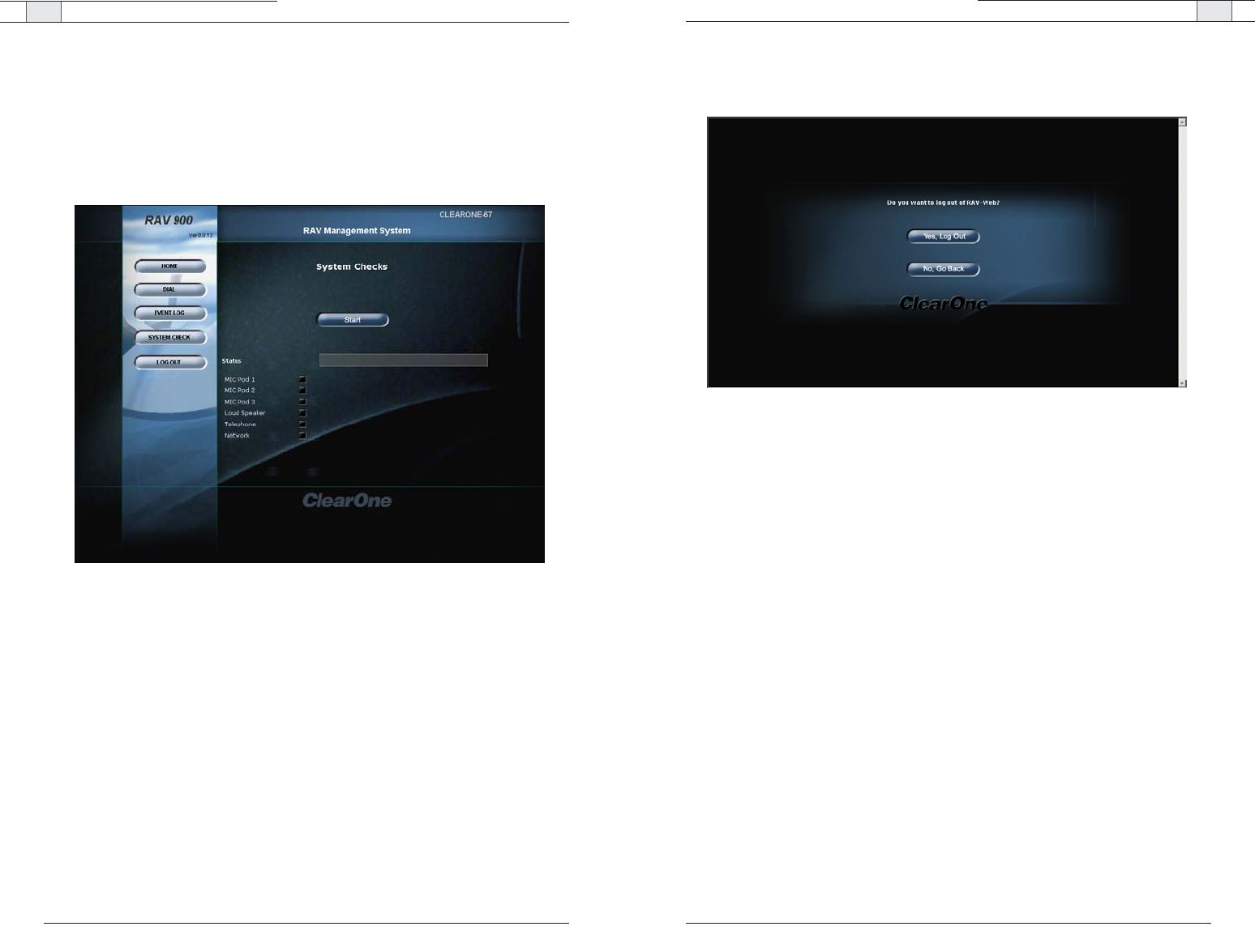
Web Interface — Overview
67
Technical Services Group ~ 1-800-283-5936 (USA) ~ 1-801-974-3760
Web Interface — Overview
66
Technical Services Group ~ 1-800-283-5936 (USA) ~ 1-801-974-3760
Log Out
• Click the
Log Out
button.
• Click
Ye s
to log out.
• Click
No
to stay logged in.
System Check
The System Diagnostic window allows you to check your RAV system to be sure all parts of
your system are connected and working properly.
To open the System Diagnostics
• Click the
System Diagnostics
button.
To run System Diagnostics
• Click the
Start
button.
RAV checks all components. When the check is complete, lights will indicate the status of
each component. Green indicates the part is connected and functioning. Red indicates a
problem with the component.
Figure 5.5. System Diagnostics
Figure 5.6. Log out

Appendix 6

Unplug all components before cleaning. Do not use liquid or aerosol cleaners. Use a soft,
damp cloth to clean the microphones and controller.
If storing for an extended period of time, remove the batteries.
Appendix — Maintenance Appendix — Troubleshooting
71
Controller
Controller doesn't communicate to the mixer.
Be sure the frequency setting on the controller is the same as the frequency setting in RAV-
Ware. Change the frequency for both to avoid frequency conflicts with other RAV systems.
Perform an RF radio test to verify the signal strength between the controller and the mixer.
The RAV Controller performs best when the RAV Mixer is positioned within line of sight
and with the antenna pointed up. Check the signal strength indicator in different areas of
the room to find the best possible operating location.The signal strength indicator is on the
LCD screen and the maximum number of bars is four.
For optimal RF connectivity, make sure the signal strength measures three or four bars in
the operating location. You can also use the RF Radio Test function on the controller for a
more detailed signal strength measurement.
To improve signal strength
• Verify that the mixer is within line of site
• Ensure the antenna is pointed up
• Do not install the mixer in a metal cabinet
You can also purchase a remote mount antenna to improve the signal strength when the
mixer is located in a different room or an enclosed cabinet.
Cannot assign a speed dial number
Any phone numbers entered using the controller are automatically assigned a speed dial of
none. Access RAV-Ware to assign speed dial numbers
Technical Services Group ~ 1-800-283-5936 (USA) ~ 1-801-974-3760
70
Troubleshooting
Technical Services Group ~ 1-800-283-5936 (USA) ~ 1-801-974-3760
Maintenance
Audio
No dial tone
Check that the RH-11 cable is connected to an analog line. Make sure the phone cable is
connected to the Line jack, not the Set jack. If you are connected to a digital line through a
telephone handset, take the handset off the hook. Run a system diagnostic check through
RAV-Ware to be sure all RAV components are working properly.
Rav does not ring
Adjust the volume of the ringer. Check that the RH-11 cable is connected. Verify that the
dialed phone number is correct.
Muffled reception
Do not move the microphone pods while on a call. Move any items that might be blocking the
microphones. Speak closer to the microphones.
Far-end party cannot hear
Check the connections of all audio inputs. Check the Audio Mixer in RAV-Ware to make sure
the correct audio paths are selected. Adjust the volume of the audio outputs.
Short silences, echoes or clipped speech on the far end
Adjust the equalization in RAV-Ware for each component.
Adjust the volume. Watch the meters. Make sure the loudest audio causes the meters to just
enter the yellow zone.
Be sure equipment is placed correctly for the best sound performance. Refer to the chapter
one for basic room design guidelines.
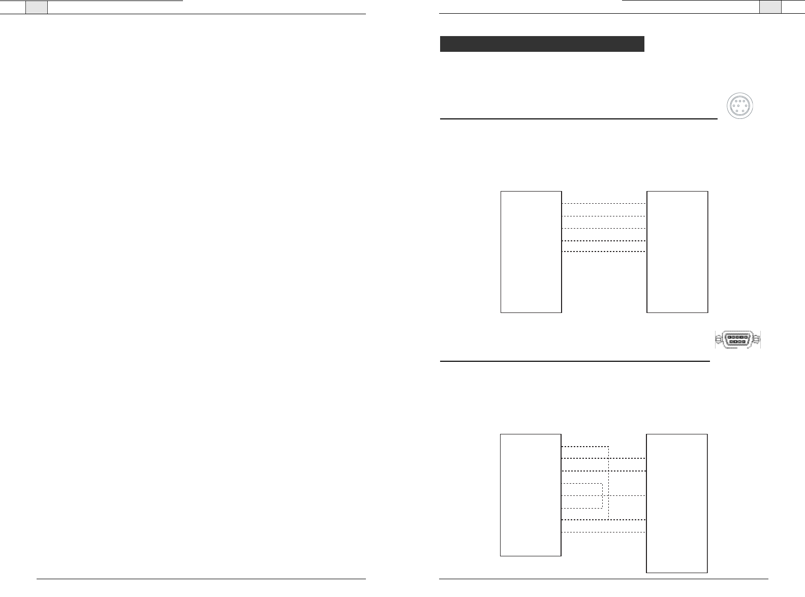
Appendix— Pinouts
73
Technical Services Group ~ 1-800-283-5936 (USA) ~ 1-801-974-3760
Appendix — Troubleshooting
72
Speakers
Neither speakers play
Check that the wires are properly connected. Check the audio mixer in RAV-ware to ensure
the audio is routed correctly.
Bass and treble are weak
Check the equalization for the loudspeakers in RAV-Ware.
Only one speaker plays
Check the equalization for the loudspeakers in RAV-Ware. Check the wires connected to the
speaker that does not play. Be sure the wires are in good condition and are firmly connected.
One speaker still does not play
Disconnect the wires from both the speaker and the mixer. Disconnect the other cord from its
speaker and connect that end of the cord to the speaker that doesn't play. If the speaker still
doesn't play, the problem is in the speaker. If the speaker now plays, continue checking for
the source of the problem. Disconnect the same cord from the mixer. Connect it to another
output. If the speaker plays, the problem is the original cord that was connected to that
speaker.
General
Physical damage to RAV
All repairs must be done by a ClearOne technician. Call ClearOne technical support for more
information.
Technical Services Group ~ 1-800-283-5936 (USA) ~ 1-801-974-3760
Camera pinouts
8 Pin Mini DIN connector
Pin Number Control Pin Number Control
1RTS5RXD
2 CTS 6 TXD
3 TXD 7 not used
4 GND 8 not used
DB-9 connector
Pin Number Control Pin Number Control
1 CD 6 DSR
2 RXD 7 RTS
3 TXD 8 CTS
4 DTR 9 RI
Pin 1 RTS
Pin 2 CTS
Pin 3 TXD
Pin 4 GND
Pin 5 RXD
Pin 6 TXD not used
Pin 7 Not used
Pin 8 Not used
Pin 2 CTS
Pin 1 RTS
Pin 5 RXD
Pin 4 GND
Pin 3 TXD
Pin 6 GND not used
Pin 7 Not used
Pin 8 Not used
8 Pin Mini DIN8 Pin Mini DIN
Pinouts
Pin 1 CD
Pin 2 RXD
Pin 3 TXD
Pin 4 DTR
Pin 5 GND
Pin 6 DSR
Pin 7 RTS
Pin 8 CTS
Pin 9 RI
Pin 2 CTS
Pin 3 TXD
Pin 5 RXD
Pin 4 GND
Pin 2 CTS
Pin 1 RTS
Pin 6 GND Not used
Pin 7 Not used
Pin 8 Not used
8 Pin Mini DINDB-9

Appendix— Specifications
75
Technical Services Group ~ 1-800-283-5936 (USA) ~ 1-801-974-3760
74
Appendix — Specifications
Technical Services Group ~ 1-800-283-5936 (USA) ~ 1-801-974-3760
Dimensions
Mixer
(WxDxH)
17" x 7.5" x 2"
(43.2 cm x 19.1 cm x 5.1 cm)
RF Controller
(WxDxH)
10.5" x 4.5" x 2.75"
Microphone Pod
Diameter 7" (17.8 cm)
Height 1.5" (3.8 cm)
Weight
Mixer 4.5 lbs (2.04 kg)
RF Controller 2.0 lbs (.91 kg)
Microphone Pod 1.1 lbs (.5 kg)
Environmental
Operating Temperature:
32º to 122º F
0º to 50º C
Power Supply
Primary Voltage: 100 to 240 VAC Auto sensing
50-60 Hz
Audio Performance
Conditions: Unless otherwise specified,all
measurements are performed with a
22 Hz to 15 kHz BW limit (no weighting)
Microphone Pod
Coverage: 360 degrees
Connection: RH-45 with Cat. 5, Link In/Out
Ports
Max Distance from Base Mixer:
50' (RAV 900), 75' (RAV 600)
Frequency Response: 60 Hz - 14 kHz (+/-1dB)
THD+N: < 0.08% (-45dBu input @ 1 kHz)
Sensitivity: -45 dBu
Input Level: -6 dBu for 1 kHz 94 dBSPL micro-
phone input
Dynamic Range: > 65dB
Line Input
Connection: Unbalanced RCA
Gain: -10 dBu nominal, adjustable from -14 dB
to +18 dB
Nominal Level: -10 dBu
Maximum Level: +9 dBu
Impedance: > 10 kOhm
Line Output
Connection: Unbalanced RCA
Nominal Level: -10 dBu, adjustable from -14 dB
to +18 dB
Maximum Level: +9 dBu
Frequency Response: 40 Hz - 15 kHz (+/-1dB)
Dynamic Range: > 80 dB
THD+N: < 0.02% (+6 dBu input @1 kHz)
Playback/Record Input
Connection: Unbalanced RCA
Gain: -10 dBu nominal, adjustable from -14 dB
to +18 dB
Nominal Level: -10 dBu
Maximum Level: +9 dBu
Impedance: > 10 kOhm
Playback/Record Output
Connection: Unbalanced RCA
Nominal Level: -10 dBu, adjustable from -14 dB
to +18 dB
Maximum Level: +9 dBu
Frequency Response: 40 Hz - 15 kHz (+/-1dB)
Dynamic Range: > 80 dB
THD+N: < 0.02% (+6 dBu input @1 kHz)
Specifications Loudspeaker
Connection: Push terminals with left and right
Power: 10 Watts into 8 Ohm load
Impedance: 8 ohm
Frequency Response: 60 Hz - 15 kHz (+/-1 dB)
Dynamic Range: > 80 dB
THD+N: < 0.5% (+5 dBu line input @1 kHz)
Output Level: 90 dBSPL output @ 1 meter
Mixer
AEC tail time: 128 ms
Adaptive noise cancellation: (6 - 18 dB)
Gating: Adaptive ambient, 1st mic priority, look
ahead gating, NOM attenuation,
Telephone Interface
Conditions: All measurements taken with
ALC disabled.
Connection: RH-11 (Set and Line Jacks)
Tail Time: 30 ms
Frequency Response: 250 Hz to 3.3 kHz (+/-1
dB)
THD+N: < 0.2% (+7 dBu line input @1 kHz)
Dynamic Range: > 60 dB
Communication I/O
10/100 Ethernet Control Port:
RH-45 with LED indicators for link, duplex and
activity status.
RS-232 Control Port:
DB9 female
9,600/19,200/38,400/57,600
(default)/115,200
baud rate: 8 bits, 1 stop, no parity
Hardware flow control on (default)/off
VISCA Camera Port:
DIN, 9600 baud, No Flow Control
USB 1.1 Configuration Port:
Slave Port
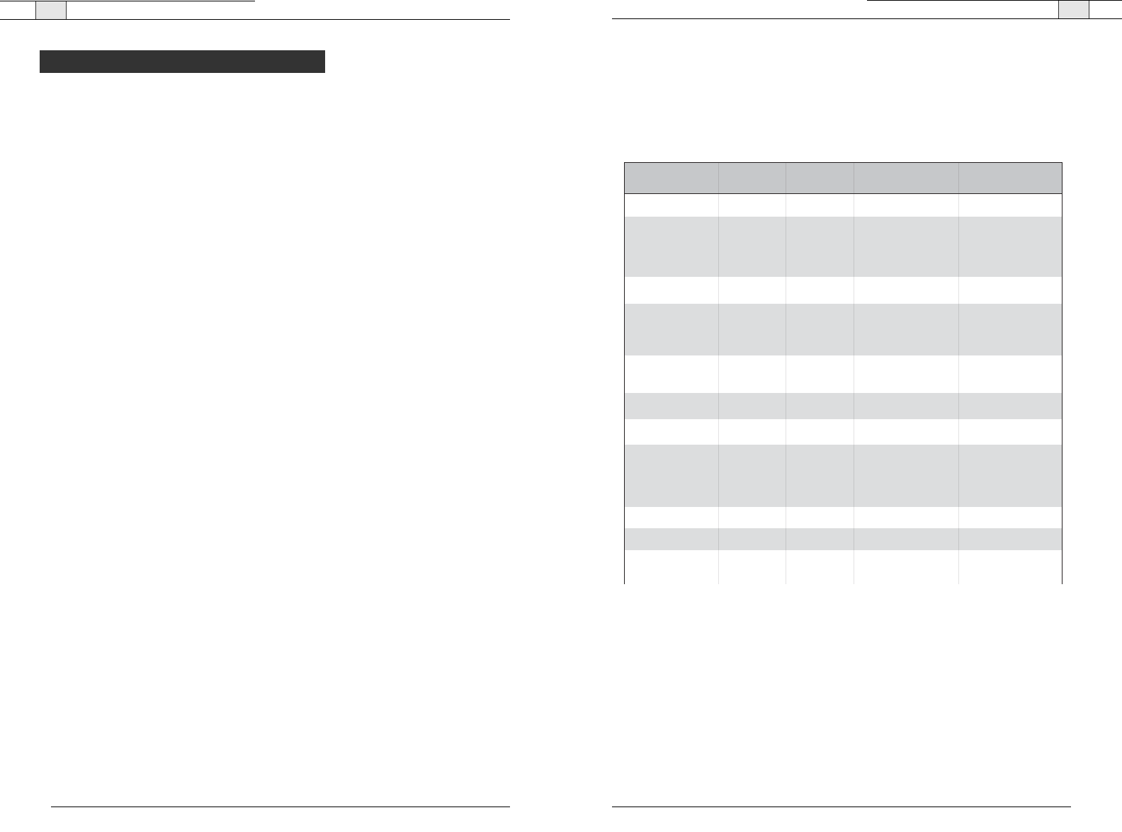
Appendix— Serial Commands
77
Appendix— Serial Commands
76
Technical Services Group ~ 1-800-283-5936 (USA) ~ 1-801-974-3760 Technical Services Group ~ 1-800-283-5936 (USA) ~ 1-801-974-3760
The RAV 600 and RAV 900 accept serial commands through the telnet, RS-232 serial port
or USB. The commands in this manual pertain only to the RAV 600 and RAV 900. RS-232
serial port protocol is 9,600, 19,200, 38,400 , 57,600 (default) or 115,200 baud; 8 bits, 1
stop bit, no parity.
Conventions
The following typographic conventions are used in this document to describe the different
serial commands. Use the Command structure section and the examples as a guide when
creating your serial commands.
Convention Description
<X> Parameters enclosed in < > indicate a mandatory parameter.
[X] Parameters enclosed in [ ] indicate an optional parameter.
1-8 Parameters separated by a - indicate a range between the values.
4,7,9 Parameters separated by a , indicate a list of available values.
BAUD Words in uppercase bold indicate command text.
DEVICE
Indicates the device type and device id.
Command structure
Commands can be either UPPER CASE or lower case. Also, extra spaces or tabs between
arguments in text commands are allowed. Return values are always in upper case. In order
for a command to be recognized by the serial port, the command must be terminated by a
carriage return.
The structure of serial commands is as follows: #TYPE DEVICE COMMAND [X] [X]
# indicates the start of a command line
DEVICE represents the device type and device number
COMMAND is the command text
[X] [X] represents any additional options in the order that they appear in the
command descriptions that follow
* placed in the Type ID or Device ID fields, the command applies to all
units or all devices respectively.
Example
A command to disable automatic gain control for Mic 2 on a RAV 600 device “0” will have
the command line: #50 AGC 2 M 0. In this command line, 5=RAV 600, 0=unit 0,
AGC=command, 2=channel, M=Mic Input group, 0=off state. If a command calls for a
“null” value, leave a blank in the command line. For example, “#50 AGC 2 M” will return
the current AGC state of Mic 2 on device 50.
Command responses will have a carriage return line feed.
Example: #50 AGC 2 M O carriage return line feed
Groups and channels
The following tables define the relationship between alpha and numeric representations. Text
commands use the alpha designation and binary commands use the numeric. In addition,
different groups have different allowable channel ranges.
Type and device IDs
Type ID Unit type Device ID range
0x8 RAV 900 0x0
0x9 RAV 600 0x0
Group Alpha Number RAV 900
Channel Range
RAV 600
Channel Range
Unknown 0 N/A N/A
Outputs O 2 1 – 3
1 is Record Out
2 is Aux Out
3 is Speaker Out
1 – 3
1 is Record Out
2 is Aux Out
3 is Speaker Out
Microphone Pod M 3 1 – 3 1 – 3
Line Inputs L 7 1 – 2
1 is Record In
2 is Aux In
1 – 2
1 is Record In
2 is Aux In
Unit
Matrix
Transmit
Local Camera
U 9 0 for Unit Values
1 for Log
0
X11 0 0
S 13 Phonebook 0
N 15 2 for HTML skin
3 for Firmware
4 for Directory
5 for Firmware Data
1
Receive
T16 1 1
R17 1 1
V19
Sony Mode: 1–7
Canon Mode: 1–9
Sony Mode: 1–7
Canon Mode: 1–9
Serial Commands

Appendix— Serial Commands
79
Appendix— Serial Commands
78
Meter type definitions
Technical Services Group ~ 1-800-283-5936 (USA) ~ 1-801-974-3760
Alpha Numeric Level position
for Mic Pods
Level position
for Line Inputs
Level position
for Outputs
Level position
for Telco Transmits
Level position
for Telco Receives
A
R
E
T
2
5
6
7
Maximum level
of the three
micropones on the
pod after processing
Level after PEQ
and gain
Level after PEQ
and gain
Level after gain Level after gain
adjustment
Echo Return Loss N/A N/A N/A N/A
N/A N/A N/A N/A
N/A N/A N/A N/A
Echo Return Loss
ERL + ERLE
Serial command error codes
Error number Text message Explanation/Solution
1 Memory error The box is out of internal memory.
Power cycle the box.
2 No command found A command was not found in the string.
3 Unknown command A command was executed on a different
device type that this box response can
not display. The command dictionary
needs to be updated.
4 Not implemented The command is not implemented.
5 Argument error The command had an argument that was
out of range.
6 Unknown command The command is unknown to this unit.
7 Bad checksum The binary command’s checksum is
wrong.
8 Camera not responding A preset or macro failed to program
because it is too large or because its
command list contained an invalid
command.
11 Command too big The binary command is too large.
RAV serial commands
Command Function
AA Selects/reports setting of auto answer
AARINGS Selects/reports setting of the number of rings to auto answer
ACONN Selects/reports status of audible connect/disconnect indication
AD Selects/reports setting of auto disconnect
AEC Selects/reports acoustic echo canceller setting
AECREF Enables/disables or reports current status of AEC reference
AGC Selects/reports AGC
BATTERYLVL Reports battery level on remote
BAUD Selects/reports the baud rate of the serial port
CALLDUR Indicates how long a call has lasted
CAMBAUD Selects/reports baud rate of camera control port
CAMCTRLMODE Sets/reports camera control port mode
CAMFLOW Selects/reports flow control of camera control port
CAMMOVE Sends command to move the camera on the camera control port
CAMPRESET Executes camera preset
CAMPRESETSET Sets current position of camera as preset
CAMPRESETSET2 Sets/reports current camera preset
CAMPOSITION Sets/reports current position of camera on the camera control port
CAMSWITCHLAG Set the switch time lag for voice tracking
CAMTRACK Selects/reports camera voice-tracking mode
CAMZOOM Sets/reports current zoom of camera on the camera control port
CLEAREFFECT Enables/disables or reports current status of clear effect
CLOCK Sets/reports current time
COUNTRY Sets/reports country for compliance.
DEFAULT Sets the unit to default
DEVICE Selects/reports manufacturer identification label
DIAL Dials DTMF sequence or reports last sequence dialed
DID Selects/reports device ID
ENETADDR Selects/reports IP Address of the Ethernet port
ENETDHCP Selects/reports use of DHCP of the Ethernet port/
ENETDNSA Selects/reports DNS server IP address of the Ethernet port
ENETDNX Selects/reports use of the DNS of the Ethernet port
ENETGATE Selects/reports default gateway of the Ethernet port
ENETSUBN Selects/reports subnet mask of the Ethernet port
EQ Enables/disables or reports current status of equalization
EQSEL Enables/disables or reports current status of equalization.
FLOW Selects/reports the flow control of the serial port
GAIN Changes/reports gain for a channel.
GATE Reports gate status of microphones
GREPORT Selects/reports gate status report frequency
HOOK Sends a hook flash
HOOKD Selects/reports hook flash duration
Technical Services Group ~ 1-800-283-5936 (USA) ~ 1-801-974-3760

Appendix— Serial Commands
81
AA - Auto Answer Enable/ Disable
This command selects/reports the setting of auto answer.
ARGUMENT DETAILS
Name Type Size Values Units
Channel Channel 1 See Group And Channels
Group Group 1 17 (R)
Value Unsigned Integer 2 0 = Off
1 = On
2 = Toggle
(Null to query in text)
BINARY FORM DETAILS
COMMAND ID
:28
NUMBER OF ARGUMENTS
:1
ARGUMENT FORM
: <Channel><Group><Value>
TEXT FORM DETAILS
COMMAND FORM
: DEVICE AA <Channel> [Value]
AARINGS - Number of Rings to Auto Answer On
This command selects/reports the setting of the number of rings to auto answer.
ARGUMENT DETAILS
Name Type Size Values Units
Channel Channel 1 See Group And Channels
Group Group 1 17 (R)
Value Unsigned Integer 2 2 or 4
(Null to query in text)
BINARY FORM DETAILS
COMMAND ID: 31
NUMBER OF ARGUMENT
S: 1
ARGUMENT FORM
: <Channel><Group><Value>
TEXT FORM DETAILS
COMMAND FORM
: DEVICE AARINGS <Channel> [Value]
Technical Services Group ~ 1-800-283-5936 (USA) ~ 1-801-974-3760
Appendix — Serial Commands
80
Technical Services Group ~ 1-800-283-5936 (USA) ~ 1-801-974-3760
Command Function
LABEL Selects/reports label of specified channel or unit
LOCALNUM Sets/reports current value of local number
LVL Reports in, out, or processor level
LVLREPORT Selects/reports level status
LVLREPORTEN Enables/Disables level reporting
MANUFACTURER Selects/reports manufacturer identification label
MICCAMPRESET Associate a microphone with a camera preset
MTRX Selects/reports matrix routing of an in. to out.
MUTE Sets/reports mute status
NCSEL Enables/Disables or reports current status of noise cancellation
PBDIAL Dials speed dial number by name
PHONEBOOKADD Saves entry in the phonebook
PHONEBOOKCNT Queries number of entries in phonebook
PHONEBOOKDEL Deletes an entry in the phonebook
PHONEBOOKREAD Queries an entry in the phonebook
REDIAL Redials last number called
RESET Resets the unit
RFFREQ Sets/reports frequency for RF link to remote.
RING Indicates a ringing line.
RINGERLVL Selects/reports audible ring level
RINGERSEL Sends/reports audible ring melody
RINGERTEST Plays current audible ringer melody
SILENCEPRST Associates camera preset with silence for voice tracking
SPEEDDIAL Dials speed dial number by speed dial number
STEREOMIX Enables/disables or reports stereo mix status
SYSCHECKS Initiates system checks
TE Selects/reports hook status
TELCOLVLCTRL Selects/reports setting of Telco TX level control
UID Reports unit ID (read only)
VER Reports unit version (read only)
VOLUME Changes/reports the gain for the output channel

Appendix— Serial Commands
83
AEC - Acoustic Echo Canceller enable/ disable
This command selects/reports the setting of Acoustic Echo Canceller.
ARGUMENT DETAILS
Name Type Size Values Units
Channel Channel 1 See Group And Channels
Group Group 1 3 (M)
Value Unsigned Integer 2 0 = Off
1 = On
2 = Toggle(Null to query in text)
BINARY FORM DETAILS
COMMAND ID
:27
NUMBER OF ARGUMENTS
:1
ARGUMENT FORM
: <Channel><Group><Value>
TEXT FORM DETAILS
COMMAND FORM
: DEVICE AEC <Channel> [Value]
AECREF - Acoustic Echo Cancellation Reference
This command enables/disables or reports the current status of the AEC reference.
ARGUMENT DETAILS
Name Type Size Values Units
Value Unsigned Integer 4 1 - 3
(Null to query in text)
BINARY FORM DETAILS
COMMAND ID
:68
NUMBER OF ARGUMENTS
:1
ARGUMENT FORM
: <Value>
TEXT FORM DETAILS
COMMAND FORM
: DEVICE AECREF [Value]
AGC - Automatic Gain Control
This command selects/reports the setting of automatic gain control.
ARGUMENT DETAILS
Name Type Size Values Units
Channel Channel 1 See Group And Channels
Group Group 1 3 (M)
Value Unsigned Integer 2 0 = Off
1 = On
2 = Toggle
(Null to query in text)
BINARY FORM DETAILS
COMMAND ID
:1
NUMBER OF ARGUMENTS
:1
ARGUMENT FORM
: <Channel><Group><Value>
TEXT FORM DETAILS
COMMAND FORM
:
DEVICE
AGC <Channel> <Group> [Value]
Technical Services Group ~ 1-800-283-5936 (USA) ~ 1-801-974-3760
Appendix — Serial Commands
82
Technical Services Group ~ 1-800-283-5936 (USA) ~ 1-801-974-3760
ACONN - Audible Connect / Disconnect Indication
This command selects/reports the status of the audible connect/disconnect indication.
ARGUMENT DETAILS
Name Type Size Values Units
Channel Channel 1 See Group And Channels
Group Group 1 17 (R)
Value Unsigned Integer 2 0 = Off
1 = On
2 = Toggle
(Null to query in text)
BINARY FORM DETAILS
COMMAND ID
:96
NUMBER OF ARGUMENTS
:1
ARGUMENT FORM
: <Channel><Group><Value>
TEXT FORM DETAILS
COMMAND FORM
: DEVICE ACONN <Channel> [Value]
AD - Auto Disconnect Enable/ Disable
This command selects/reports the setting of auto disconnect.
ARGUMENT DETAILS
Name Type Size Values Units
Channel Channel 1 See Group And Channels
Group Group 1 17 (R)
Value Unsigned Integer 2 0 = Off
1 = Loop Drop
2 = Call Progress
3 = Loop Drop + Call Progress
(Null to query in text)
BINARY FORM DETAILS
COMMAND ID
:29
NUMBER OF ARGUMENTS
:1
ARGUMENT FORM
: <Channel><Group><Value>
TEXT FORM DETAILS
COMMAND FORM
: DEVICE AD <Channel> [Value]

Appendix— Serial Commands
85
CALLDUR - Call Duration
This command indicates how long a call has lasted. If no call is in session, this will report 0. At the
time of call termination, this command will automatically be sent out reporting the duration.
ARGUMENT DETAILS
Name Type Size Values Units
Channel Channel 1 See Group And Channels
Group Group 1 17 (R)
Reserved 2 0
Duration String 8 String of format
HR:MN:SS
BINARY FORM DETAILS
COMMAND ID
:63
NUMBER OF ARGUMENTS
:3
ARGUMENT FORM
: <Channel><Group><Reserved><Duration>
TEXT FORM DETAILS
COMMAND FORM
: DEVICE CALLDUR <Channel> <Duration>
CAMBAUD - Camera Control Baud Rate
This command selects/reports the baud rate of the camera control serial port.
ARGUMENT DETAILS
Name Type Size Values Units
Value Unsigned Integer 4 2400, 9600, 19200, 38400
(Null to query in text)
BINARY FORM DETAILS
COMMAND ID
:60
NUMBER OF ARGUMENTS
:1
ARGUMENT FORM
: <Value>
TEXT FORM DETAILS
COMMAND FORM
: DEVICE CAMBAUD [Value]
CAMCTRLMODE - Camera Control Port Mode
This command sets/reports the camera control port mode.
ARGUMENT DETAILS
Name Type Size Values Units
Value Unsigned Integer 4 0 = Sony
1 = Canon
(Null to Query in Text)
BINARY FORM DETAILS
COMMAND ID
:50
NUMBER OF ARGUMENTS
:1
ARGUMENT FORM
: <Value>
TEXT FORM DETAILS
COMMAND FORM
: DEVICE CAMCTRLMODE [Value]
Technical Services Group ~ 1-800-283-5936 (USA) ~ 1-801-974-3760
Appendix — Serial Commands
84
BATTERYLVL - Battery Level
This command reports the battery level on the remote. If the batteries run low, this command will
automatically be sent out reporting the low indication.
ARGUMENT DETAILS
Name Type Size Values Units
Value Unsigned Integer 4 0 = battery level unavailable
1 = Lowest
2
3
4
5 = Highest
(Null to query in text.)
BINARY FORM DETAILS
COMMAND ID
:65
NUMBER OF ARGUMENTS
:1
ARGUMENT FORM
: <Value>
TEXT FORM DETAILS
COMMAND FORM
DEVICE BATTERYLVL [Value]
BAUD - Baud Rate
This command selects/reports the baud rate of the serial port.
ARGUMENT DETAILS
Name Type Size Values Units
Value Unsigned Integer 4 9600, 19200, 38400,
57600,115200
(Null to query in text)
BINARY FORM DETAILS
COMMAND ID
:2
NUMBER OF ARGUMENTS
:1
ARGUMENT FORM
: <Value>
TEXT FORM DETAILS
COMMAND FORM
: DEVICE BAUD [Value]
Attention
: If you are connected to the RAV unit through the serial port, you will need to reboot
the unit before the baud rate and flow control changes take place. If you are connected to the
RAV unit through the USB port, changes are made instantly.
Technical Services Group ~ 1-800-283-5936 (USA) ~ 1-801-974-3760

Appendix — Serial Commands
87
CAMPRESET - Camera Preset
Executes a camera preset.There is no query for this command.
ARGUMENT DETAILS
Name Type Size Values Units
Value Unsigned Integer 4 1 - 10
BINARY FORM DETAILS
COMMAND ID
:51
NUMBER OF ARGUMENTS
:1
ARGUMENT FORM
: <Value>
TEXT FORM DETAILS
COMMAND FORM
: DEVICE CAMPRESET [Value]
CAMPRESETSET - Camera Preset Setup
This command sets the current position of a camera as a camera preset. There is no query for this
command.
ARGUMENT DETAILS
Name Type Size Values Units
Preset Unsigned Integer 2 1 - 10
Channel Channel 1 See Group And Channels
Group Group 1 19 (V)
Label String 16
BINARY FORM DETAILS
COMMAND ID
:52
NUMBER OF ARGUMENTS
:5
ARGUMENT FORM
: <Preset><Channel><Group><Label>
TEXT FORM DETAILS
COMMAND FORM
: DEVICE CAMPRESETSET <Preset Channel Group Label>
Technical Services Group ~ 1-800-283-5936 (USA) ~ 1-801-974-3760
Appendix — Serial Commands
86
CAMFLOW - Camera Control Flow Control
This command selects/reports the flow control of the camera control serial port on the unit.
Hardware flow control is implemented using DTR and DSR.
ARGUMENT DETAILS
Name Type Size Values Units
Value Unsigned Integer 4 0 = Off
1 = On
2 = Toggle
(Null to query in text)
BINARY FORM DETAILS
COMMAND ID
:61
NUMBER OF ARGUMENTS
:1
ARGUMENT FORM
: <Value>
TEXT FORM DETAILS
COMMAND FORM
: DEVICE CAMFLOW [Value]
CAMMOVE - Move the Camera
This command sends commands to move the camera on the camera control port. There is no query
for this command.
ARGUMENT DETAILS
Name Type Size Values Units
Channel Channel 1 See Group And Channels
Group Group 1 19 (V)
Value Unsigned Integer 2 0 = Stop
1 = Pan Right
2 = Pan Left
3 = Tilt Up
4 = Tilt Down
5 = Zoom In
6 = Zoom Out
BINARY FORM DETAILS
COMMAND ID
:49
NUMBER OF ARGUMENTS
:1
ARGUMENT FORM
: <Channel><Group><Value>
TEXT FORM DETAILS
COMMAND FORM
: DEVICE CAMMOVE <Channel Group> [Value]
Technical Services Group ~ 1-800-283-5936 (USA) ~ 1-801-974-3760

Appendix — Serial Commands
89
CAMSWITCHLAG - Camera Switch Time Lag
This command set the switch time lag for voice tracking.
ARGUMENT DETAILS
Name Type Size Values Units
Value Unsigned Float 4 0.00 - 5.00 S
BINARY FORM DETAILS
COMMAND ID
:76
NUMBER OF ARGUMENTS
:1
ARGUMENT FORM
: <Value>
TEXT FORM DETAILS
COMMAND FORM
: DEVICE CAMSWITCHLAG [Value]
CAMTRACK - Camera Track
This command selects/reports the camera voice tracking mode.
ARGUMENT DETAILS
Name Type Size Values Units
Value Unsigned Integer 4 0 = Off
1 = On
2 = Toggle
(Null to query in text)
BINARY FORM DETAILS
COMMAND ID
:57
NUMBER OF ARGUMENTS
:1
ARGUMENT FORM
: <Value>
TEXT FORM DETAILS
COMMAND FORM
: DEVICE CAMTRACK [Value]
CAMZOOM - Camera Zoom
This command sets or reports the current Zoom of the camera on the camera control port.
ARGUMENT DETAILS
Name Type Size Values Units
Channel Channel 1 See Group And Channels
Group Group 1 19 (V)
Zoom Angle Signed Float 2 If Sony, 6.6 to 65. Degrees
If Canon, 3 to 47.5.
(NULL to Query in Text).
BINARY FORM DETAILS
COMMAND ID
:54
NUMBER OF ARGUMENTS
:1
ARGUMENT FORM
: <Channel><Group><Zoom Angle>
TEXT FORM DETAILS
COMMAND FORM
: DEVICE CAMZOOM <Channel Group> [Zoom]
Technical Services Group ~ 1-800-283-5936 (USA) ~ 1-801-974-3760
Appendix — Serial Commands
88
CAMPRESETSET2 - Camera Preset Setup 2
This command sets or reports the current camera preset.
ARGUMENT DETAILS
Name Type Size Values Units
Preset Unsigned Integer 2 1 - 10
Channel Channel 1 See Group And Channels
Group Group 1 19 (V)
Pan Angle Signed Float 2 If Sony, -100 to 100. Degrees
If Canon, -100 to 100.
(NULL to Query in Text)
Tilt Angle Signed Float 2 If Sony, -25 to 25. Degrees
If Canon, -30 to 90.
Zoom Angle Signed Float 4 If Sony, 6.6 to 65. Degrees
If Canon, 3 to 47.5.
Label String 16
BINARY FORM DETAILS
COMMAND ID
:56
NUMBER OF ARGUMENTS
:7
ARGUMENT FORM
: <Preset><Channel><Group><Pan><Tilt><Zoom><Label>
TEXT FORM DETAILS
COMMAND FORM
: DEVICE CAMPRESETSET2 <Preset>[Channel Group Pan Tilt Zoom Label]
CAMPOSITION - Camera Position
This command sets or reports the current position of the camera on the camera control port.
ARGUMENT DETAILS
Name Type Size Values Units
Channel Channel 1 See Group And Channels
Group Group 1 19 (V)
Pan Angle Signed Float 2 If Sony, -100 to 100. Degrees
If Canon, -100 to 100.
(NULL to Query in Text)
Tilt Angle Signed Float 4 If Sony, -25 to 25. Degrees
If Canon, -30 to 30.
BINARY FORM DETAILS
COMMAND ID
:53
NUMBER OF ARGUMENTS
:2
ARGUMENT FORM
: <Channel><Group><Pan Angle><Tilt Angle>
TEXT FORM DETAILS
COMMAND FORM
: DEVICE CAMPOSITON <Channel Group> [Pan Tilt]
Technical Services Group ~ 1-800-283-5936 (USA) ~ 1-801-974-3760

Appendix — Serial Commands
91
COUNTRY - Country Selection
This command sets / reports the country for compliance.
ARGUMENT DETAILS
Name Type Size Values Units
Value Unsigned Integer 4 1 = US / Canada
2 = Europe
3 = Mexico
4 = Australia / New Zealand
5 = South Africa
6 = Japan
7 = Brazil
8 = South Korea
9 = China
10 = Singapore
11 = Taiwan
(Null to query in text)
BINARY FORM DETAILS
COMMAND ID
:40
NUMBER OF ARGUMENTS
:1
ARGUMENT FORM
: <Value>
TEXT FORM DETAILS
COMMAND FORM
: DEVICE COUNTRY [Value]
DEFAULT - Default The Unit
Sets the unit to factory defaults. There is no query for this command.
ARGUMENT DETAILS
None
BINARY FORM DETAILS
COMMAND ID
:17
NUMBER OF ARGUMENTS
:1
ARGUMENT FORM
: <0>
TEXT FORM DETAILS
COMMAND FORM
: DEVICE DEFAULT
Attention
: The unit will need to be rebooted after sending the DEFAULT command.
Technical Services Group ~ 1-800-283-5936 (USA) ~ 1-801-974-3760
Appendix — Serial Commands
90
CLEAREFFECT - Clear Effect Wide Band Telco Emulation
This command enables/disables or reports the current status of the clear effect.
ARGUMENT DETAILS
Name Type Size Values Units
Channel Channel 1 See Group And Channels
Group Group 1 17 (T)
Value Unsigned Integer 2 0 = Off
1 = On
2 = Toggle
(Null to query in text)
BINARY FORM DETAILS
COMMAND ID
:66
NUMBER OF ARGUMENTS
:1
ARGUMENT FORM
: <Channel><Group><Value>
TEXT FORM DETAILS
COMMAND FORM
: DEVICE CLEAREFFECT <Channel> [Value]
CLOCK - Clock Set
This command sets or reports the current time.
ARGUMENT DETAILS
Name Type Size Values Units
Date Unsigned Integer 1 1 - 31
Month Unsigned Integer 1 1 - 12
Year Unsigned Integer 2 2000 - 2099
( NULL to Query in Text)
Hours Unsigned Integer 1 00 - 23
Minutes Unsigned Integer 1 00 - 59
Seconds Unsigned Integer 1 00 - 59
Day of Week Unsigned Integer 1 1 = Sunday
2 = Monday
3 = Tuesday
4 = Wednesday
5 = Thursday
6 = Friday
7 = Saturday
BINARY FORM DETAILS
COMMAND ID
:64
NUMBER OF ARGUMENTS
:2
ARGUMENT FORM
: <Date><Month><Year><Hours><Minutes><Seconds><Day>
TEXT FORM DETAILS
COMMAND FORM
: DEVICE CLOCK [Date Month Year Hours Minutes Seconds Day]
Technical Services Group ~ 1-800-283-5936 (USA) ~ 1-801-974-3760

Appendix — Serial Commands
93
ENETADDR - Ethernet port IP address
This command selects/reports the IP address of the Ethernet port on the unit.
ARGUMENT DETAILS
Name Type Size Values Units
Value IP Address 4 (Null to query in text)
BINARY FORM DETAILS
COMMAND ID
:21
TEXT FORM DETAILS
COMMAND FORM
: DEVICE DID [Value]
NUMBER OF ARGUMENTS
:1
ARGUMENT FORM
: <Value>
TEXT FORM DETAILS
COMMAND FORM
: DEVICE ENETADDR [Value]
ENETDHCP - Ethernet DHCP Selection
This command selects/reports the use of DHCP of the Ethernet port on the unit.
ARGUMENT DETAILS
Name Type Size Values Units
Value Unsigned Integer 4 0 = On
1 = Off
2 = Toggle
(Null to query in text)
BINARY FORM DETAILS
COMMAND ID
:25
NUMBER OF ARGUMENTS
:1
ARGUMENT FORM
: <Value>
TEXT FORM DETAILS
COMMAND FORM
: DEVICE ENETDHCP [Value]
ENETDNSA - Ethernet DNS Server addresses
This command selects/reports the DNS servers IP addresses of the Ethernet port on the unit.
ARGUMENT DETAILS
Name Type Size Values Units
Value IP Address 4 (Null to query in text)
BINARY FORM DETAILS
COMMAND ID
:24
NUMBER OF ARGUMENTS
:1
ARGUMENT FORM
: <Value>
TEXT FORM DETAILS
COMMAND FORM
: DEVICE ENETDNSA [Value]
Technical Services Group ~ 1-800-283-5936 (USA) ~ 1-801-974-3760
Appendix — Serial Commands
92
DEVICE - Device Identification Label
This selects/reports the manufacturer identification label of the specific channel.
ARGUMENT DETAILS
Name Type Size Values Units
Channel Channel 1 See Group And Channels
Group Group 1 2, 3, 7(O, M, L)
Reserved Unsigned Integer 2 0
Label String 32 1 - 32 characters
CLEAR = clear the label
(Null to query in text)
BINARY FORM DETAILS
COMMAND ID
:82
NUMBER OF ARGUMENTS
:9
ARGUMENT FORM
: <Channel><Group><Reserved><Value>
TEXT FORM DETAILS
COMMAND FORM
: DEVICE DEVICE <Channel> <Group> [Value]
DIAL - DTMF Dialing
This command dials a DTMF sequence or reports back the last sequence dialed.
ARGUMENT DETAILS
Name Type Size Values Units
Channel Channel 1 See Group And Channels
Group Group 1 17 (R)
Reserved 2 0
Number String 44 1 - 44 Chars of '0' - '9', 'A' - 'D', '*', '#', ','
(Null to query last number dialed in text)
BINARY FORM DETAILS
COMMAND ID
:30
NUMBER OF ARGUMENTS
:12
ARGUMENT FORM
: <Channel><Group><Number>
TEXT FORM DETAILS
COMMAND FORM
: DEVICE DIAL <Channel> [Number]
DID - Device ID
This command reports the device id.This command is read only.
ARGUMENT DETAILS
Name Type Size Values Units
Value Unsigned Integer 4 See Type And Device IDs
(Null sent in text, Value returned)
BINARY FORM DETAILS
COMMAND ID
:3
NUMBER OF ARGUMENTS
:1
ARGUMENT FORM
: <Value>
Technical Services Group ~ 1-800-283-5936 (USA) ~ 1-801-974-3760

Appendix — Serial Commands
95
EQ - Equalization
This command enables/disables or reports the current status of the equalization on the input or out-
put.
ARGUMENT DETAILS
Name Type Size Values Units
Channel Channel 1 See Group And Channels
Group Group 1 2, 7 (O, L)
High Gain Signed Float 2 -12.00 - 12.00
(Null to query in text)
Mid Gain Signed Float 2 -12.00 - 12.00
Low Gain Signed Float 2 -12.00 - 12.00
BINARY FORM DETAILS
COMMAND ID
:67
NUMBER OF ARGUMENTS
:2
ARGUMENT FORM
: <Channel><Group><High Gain><Mid Gain><Low Gain>
TEXT FORM DETAILS
COMMAND FORM
: DEVICE EQ <Channel> <Group> [High Mid Low]
EQSEL - Equalization Enable
This command enables/disables or reports the current status of the equalization on the input or out-
put.
ARGUMENT DETAILS
Name Type Size Values Units
Channel Channel 1 See Group And Channels
Group Group 1 2, 7 (O, L)
Value Unsigned Integer 2 0 = Off
1 = On
2 = Toggle
(NULL to query in text)
BINARY FORM DETAILS
COMMAND ID
:74
NUMBER OF ARGUMENTS
:1
ARGUMENT FORM
: <Channel><Group><Value>
TEXT FORM DETAILS
COMMAND FORM
: DEVICE EQSEL <Channel> <Group> [Value]
Technical Services Group ~ 1-800-283-5936 (USA) ~ 1-801-974-3760
Appendix — Serial Commands
94
ENETDNX - Ethernet DNS Selection
This command selects/reports the use of DNS of the Ethernet port on the unit.
ARGUMENT DETAILS
Name Type Size Values Units
Value Unsigned Integer 4 0 = On
1 = Off
2 = Toggle
(Null to query in text)
BINARY FORM DETAILS
COMMAND ID
:26
NUMBER OF ARGUMENTS
:1
ARGUMENT FORM
: <Value>
TEXT FORM DETAILS
COMMAND FORM
: DEVICE ENETDNS [Value]
ENETGATE - Ethernet default Gateway address
This command selects/reports the default gateway of the Ethernet port on the unit.
ARGUMENT DETAILS
Name Type Size Values Units
Value IP Address 4 (Null to query in text)
BINARY FORM DETAILS
COMMAND ID
:23
NUMBER OF ARGUMENTS
:1
ARGUMENT FORM
: <Value>
TEXT FORM DETAILS
COMMAND FORM
: DEVICE ENETGATE [Value]
ENETSUBN - Ethernet subnet mask
This command selects/reports the Subnet mask of the Ethernet port on the unit.
ARGUMENT DETAILS
Name Type Size Values Units
Value IP Address 4 (Null to query in text)
BINARY FORM DETAILS
COMMAND ID
:22
NUMBER OF ARGUMENTS
:1
ARGUMENT FORM
: <Value>
TEXT FORM DETAILS
COMMAND FORM
: DEVICE ENETSUBN [Value]
Technical Services Group ~ 1-800-283-5936 (USA) ~ 1-801-974-3760

Appendix — Serial Commands
97
GREPORT - Gate Report
This command selects/reports the mode of gate status reporting.
ARGUMENT DETAILS
Name Type Size Values Units
Value Unsigned Integer 4 0 = Off
1 = On
2 = Toggle
(Null to query in text)
BINARY FORM DETAILS
COMMAND ID
:7
NUMBER OF ARGUMENTS
:1
ARGUMENT FORM
: <Value>
TEXT FORM DETAILS
COMMAND FORM
: DEVICE GREPORT [Value]
HOOK - Hook Flash
This command sends a hook flash. There is no query for this command.
ARGUMENT DETAILS
Name Type Size Values Units
Channel Channel 1 See Group And Channels
Group Group 1 17 (R)
Reserved 2 0
BINARY FORM DETAILS
COMMAND ID
:32
NUMBER OF ARGUMENTS
:1
ARGUMENT FORM
: <Channel><Group><Reserved>
TEXT FORM DETAILS
COMMAND FORM
: DEVICE HOOK <Channel>
HOOKD - Hook Flash Duration
This command selects/reports the hook flash duration.
ARGUMENT DETAILS
Name Type Size Values Units
Channel Channel 1 See Group And Channels
Group Group 1 17 (R)
Value Unsigned Integer 2 50 - 1000 Ms
(Null to query in text)
BINARY FORM DETAILS
COMMAND ID
:33
NUMBER OF ARGUMENT
S: 1
ARGUMENT FORM
: <Channel><Group><Value>
TEXT FORM DETAILS
COMMAND FORM
: DEVICE HOOKD <Channel> [Value]
Technical Services Group ~ 1-800-283-5936 (USA) ~ 1-801-974-3760
96
Technical Services Group ~ 1-800-283-5936 (USA) ~ 1-801-974-3760
Appendix — Serial Commands
FLOW - Flow Control
This command selects/reports the flow control of the serial port on the unit. Hardware flow control is
implemented using DTR and DSR.
ARGUMENT DETAILS
Name Type Size Values Units
Value Unsigned Integer 4 0 = Off
1 = On
2 = Toggle
(Null to query in text)
BINARY FORM DETAILS
COMMAND ID
:4
NUMBER OF ARGUMENTS
:1
ARGUMENT FORM
: <Value>
TEXT FORM DETAILS
COMMAND FORM
: DEVICE FLOW [Value]
GAIN - Gain Adjustment
This command changes or reports back the gain for a channel.
ARGUMENT DETAILS
Name Type Size Values Units
Channel Channel 1 See Group And Channels
Group Group 1 2,3,7,16,17 (O,M,L,T,R)
Value Signed Float 2 -99.90 - 99.90 **(Null to query in text) DB
Absol / Rel 0 A = AbsoluteR = RelativeNull = Relative
BINARY FORM DETAILS
COMMAND ID
:5
NUMBER OF ARGUMENTS
:1
ARGUMENT FORM
: <Channel><Group><Value>
TEXT FORM DETAILS
COMMAND FORM
: DEVICE GAIN <Channel> <Group> [Value] [Absol/Rel]
** Note: Values indicate entry range only. Actual internal range of the gain stage is from -14 to 18.
Absolute values will be limited to the internal gain range.
GATE - Gate Status
This command reports the gate status of Mics. This command is read only.
ARGUMENT DETAILS
Name Type Size Values Units
Value Hexadecimal 4 Bits 0 - 8 represent
gate status on Mics 1 - 9
(Null sent in text, Value returned)
BINARY FORM DETAILS
COMMAND ID
:6
NUMBER OF ARGUMENTS
:1
ARGUMENT FORM
: <Value>
TEXT FORM DETAILS
COMMAND FORM
: DEVICE GATE [Value]

Appendix — Serial Commands
99
Appendix — Serial Commands
98
Technical Services Group ~ 1-800-283-5936 (USA) ~ 1-801-974-3760
LVL - Level
This command reports the level of a channel.This command is read only.
ARGUMENT DETAILS
Name Type Size Values Units
Channel Channel 1 See Group And Channels
Group Group 1 2, 3, 7, 16, 17(O, M, L,T, R)
Position Meter Type 2 See MeterTypeDefinitions
Value Signed Float 4 -99.99 - 99.99 DB
(Sent with Null in text,
Value returned)
BINARY FORM DETAILS
COMMAND ID
:9
NUMBER OF ARGUMENTS
:2
ARGUMENT FORM
: <Channel><Group><Position><Value>
TEXT FORM DETAILS
COMMAND FORM
: DEVICE LVL <Channel> <Group> <Position> [Value]
LVLREPORT - Level Report
This command selects/reports the status of level reporting for the specified channel.
ARGUMENT DETAILS
Name Type Size Values Units
Channel Channel 1 See Group And Channels
Group Group 1 2,3,7,16,17 (O,M,L,T,R)
Position Meter Type 2 See MeterTypeDefinitions
Value Unsigned Integer 4 0 = Off (Delete from list being reported)
1 = On (Add to list being reported)
2 = Toggle(Null to query in text)
BINARY FORM DETAILS
COMMAND ID
:10
NUMBER OF ARGUMENTS
:2
ARGUMENT FORM
: <Channel><Group><Position><Value>
TEXT FORM DETAILS
COMMAND FORM
: DEVICE LVLREPORT <Channel> <Group> <Position> [Value]
Note: Level reporting for the unit must also be enabled (LVLREPORTEN).
Technical Services Group ~ 1-800-283-5936 (USA) ~ 1-801-974-3760
LABEL - Label
This selects/reports the label of the specific channel or the unit.
ARGUMENT DETAILS
Name Type Size Values Units
Channel Channel 1 See Group And Channels
Group Group 1 2,3,7,9,16,17 (O,M,L,U,T,R)
Reserved Unsigned Integer 2 0
Label String 32 For group U, 1 - 11 characters
All other, 1 - 32 characters
If not group U, CLEAR = clear the label
(Null to query in text)
BINARY FORM DETAILS
COMMAND ID
:8
NUMBER OF ARGUMENTS
:9
ARGUMENT FORM
: <Channel><Group><Reserved><Value>
TEXT FORM DETAILS
COMMAND FORM
: DEVICE LABEL <Channel> <Group> [Value]
LOCALNUM -
Local Number
This command sets or reports back the current value of the local number.
ARGUMENT DETAILS
Name Type Size Values Units
Channel Channel 1 See Group And Channels
Group Group 1 17 (R)
Reserved 2 0
Number String 16 1 - 16 Chars of '0' - '9', 'A' - 'D', '*', '#', ','
(Null to query in text)
BINARY FORM DETAILS
COMMAND ID
:59
NUMBER OF ARGUMENTS
:5
ARGUMENT FORM
: <Channel><Group><Number>
TEXT FORM DETAILS
COMMAND FORM
: DEVICE LOCALNUM <Channel> [Number]

101
Technical Services Group ~ 1-800-283-5936 (USA) ~ 1-801-974-3760
Appendix — Serial Commands
100
LVLREPORTEN - Level Report Enable
Enables level reporting for the unit.
ARGUMENT DETAILS
Name Type Size Values Units
Value Unsigned Integer 4 0 = Turn off reporting but leave current list
1 = Turn on reporting
2 = Turn off reporting and clear the list
(Null to query in text)
BINARY FORM DETAILS
COMMAND ID
:16
NUMBER OF ARGUMENTS
:1
ARGUMENT FORM
: <Value>
TEXT FORM DETAILS
COMMAND FORM
: DEVICE LVLREPORTEN [Value]
MANUFACTURER - Manufacturer Identification Label
This selects/reports the manufacturer identification label of the specific channel.
ARGUMENT DETAILS
Name Type Size Values Units
Channel Channel 1 See Group And Channels
Group Group 1 2, 3, 7(O, M, L)
Reserved Unsigned Integer 2 0
Label String 32 1 - 32 characters
CLEAR = clear the label
(Null to query in text)
BINARY FORM DETAILS
COMMAND ID
:81
NUMBER OF ARGUMENTS
:9
ARGUMENT FORM
: <Channel><Group><Reserved><Value>
TEXT FORM DETAILS
COMMAND FORM
: DEVICE MANUFACTURER <Channel> <Group> [Value]
Technical Services Group ~ 1-800-283-5936 (USA) ~ 1-801-974-3760
Appendix— Serial Commands
MICCAMPRESET - Mic Camera Preset
This command associates a mic with a camera preset for voice tracking.
ARGUMENT DETAILS
Name Type Size Values Units
Channel Channel 1 See Group And Channels
Group Group 1 3 (M)
Value Unsigned Integer 2 0 to Clear
1 - 10
(NULL to Query in Text)
BINARY FORM DETAILS
COMMAND ID
:55
NUMBER OF ARGUMENTS
:1
ARGUMENT FORM
: <Channel><Group><Value>
TEXT FORM DETAILS
COMMAND FORM
: DEVICE MICCAMPRESET <Channel> [Value]
MTRX - Matrix Routing
This command selects/reports the matrix routing of an input to an output.
ARGUMENT DETAILS
Name Type Size Values Units
Source Channel Channel 1 See Group And Channels
Source Group Group 1 3, 7, 17(M, L, R)
Destination Channel Channel 1 Group 3 (M) is only allowed all channels.
All other groups cannot have the all
channel. (See Group And Channels)
Destination Group Group 1 2, 16(O, T)
Value Unsigned Integer 4 0 = Cross point off
1 = Cross point on
2 = Toggle
(Null to query in text)
BINARY FORM DETAILS
COMMAND ID
:11
NUMBER OF ARGUMENTS
:2
ARGUMENT FORM
: <Src. Ch.><Src. Gp.><Dest. Ch.><Dest. Gp.><Value>
TEXT FORM DETAILS
COMMAND FORM
: DEVICE MTRX <Src. Ch.> <Src. Gp.> <Dest. Ch.> <Dest. Gp.>
[Value]

Appendix — Serial Commands
103
Technical Services Group ~ 1-800-283-5936 (USA) ~ 1-801-974-3760
Appendix — Serial Commands
102
MUTE - Mute
This command selects/reports the setting of mute on a channel.
ARGUMENT DETAILS
Name Type Size Values Units
Channel Channel 1 See Group And Channels
Group Group 1 3 (M) (all channels only)
Value Unsigned Integer 2 0 = Off
1 = On
2 = Toggle
(Null to query in text)
BINARY FORM DETAILS
COMMAND ID
:12
NUMBER OF ARGUMENTS
:1
ARGUMENT FORM
: <Channel><Group><Value>
TEXT FORM DETAILS
COMMAND FORM
: DEVICE MUTE <Channel> <Group> [Value]
NCSEL - Noise Cancellation Select
This command enables/disables or reports the current status of noise cancellation.
ARGUMENT DETAILS
Name Type Size Values Units
Channel Channel 1 See Group And Channels
Group Group 1 3,17 (M, R)
Value Unsigned Integer 2 0 = Off
1 = On
2 = Toggle
(Null to query in text)
BINARY FORM DETAILS
COMMAND ID
:62
NUMBER OF ARGUMENTS
:1
ARGUMENT FORM
: <Channel><Group><Value>
TEXT FORM DETAILS
COMMAND FORM
: DEVICE NCSEL <Channel> <Group> [Value]
Technical Services Group ~ 1-800-283-5936 (USA) ~ 1-801-974-3760
PBDIAL - Dial a PB Entry by Name
This command dials a speed dial number by name.There is no query for this command.
ARGUMENT DETAILS
Name Type Size Values Units
Channel Channel 1 See Group And Channels
Group Group 1 17 (R)
Reserved Unsigned Integer 2 0
Label String 16 1 - 16 chars
BINARY FORM DETAILS
COMMAND ID
:36
NUMBER OF ARGUMENTS
:5
ARGUMENT FORM
: <Channe><Group><Reserved><Label>
TEXT FORM DETAILS
COMMAND FORM
: DEVICE PBDIAL <Channel> <Label>
PHONEBOOKADD - Adds an Entry to the Phonebook
This command saves an entry in the phonebook.There is no query. No two entries can share the same
label. An argument error will be returned if an entry already has the name. To change an entry, you
must first delete it and then add it again. If label is blank, the first 20 characters of the number will
be used as the label. Number must not be blank. If an entry already exists with the assigned speed
dial it will be overwritten. Speed Dial 34 is the conference number and is always stored first in the
Phonebook.The rest of the entries are alphabetized base on Label.
ARGUMENT DETAILS
Name Type Size Values Units
Speed Dial Unsigned Integer 4 0 for not assigned to a speed dial
1 - 19
20 for Conference
Number String 44 1 - 44 chars
'0' - '9', 'A' - 'D', '*', '#'
Label String 16 1 - 16 chars
BINARY FORM DETAILS
COMMAND ID
:38
NUMBER OF ARGUMENTS
:16
ARGUMENT FORM
: <ID><Number><Label>
TEXT FORM DETAILS
COMMAND FORM
: DEVICE PHONEBOOKADD <ID Number Label>

Appendix — Serial Commands
105
REDIAL - Dial the last number again
This command redials the last number.There is no query for this command.
ARGUMENT DETAILS
Name Type Size Values Units
Channel Channel 1 See Group And Channels
Group Group 1 17 (R)
Reserved 2 0
BINARY FORM DETAILS
COMMAND ID
:45
NUMBER OF ARGUMENTS
:1
ARGUMENT FORM
: <Channel><Group><Reserved>
TEXT FORM DETAILS
COMMAND FORM
: DEVICE REDIAL <Channel>
RESET - Reset
Resets the unit.There is no query for this command.
ARGUMENT DETAILS
None
BINARY FORM DETAILS
COMMAND ID
:20
NUMBER OF ARGUMENTS
:1
ARGUMENT FORM
: <0>
TEXT FORM DETAILS
COMMAND FORM
: DEVICE RESET
RETURN VALUES
The box is reset and the boot up message is displayed.
Technical Services Group ~ 1-800-283-5936 (USA) ~ 1-801-974-3760
Appendix — Serial Commands
104
PHONEBOOKCNT - Queries the Number of Entries in the Phonebook
This command queries the number of entries in the phonebook.This command is query only.
ARGUMENT DETAILS
Name Type Size Values Units
Value Unsigned Integer 4 0 - 20
BINARY FORM DETAILS
COMMAND ID
:78
NUMBER OF ARGUMENTS
:1
ARGUMENT FORM
: <Value>
TEXT FORM DETAILS
COMMAND FORM
: DEVICE PHONEBOOKCNT <Value>
PHONEBOOKDEL - Deletes an Entry to the Phonebook
This command deletes an entry in the phonebook. There is no query.
ARGUMENT DETAILS
Name Type Size Values Units
Label String 16 1 - 16 chars
BINARY FORM DETAILS
COMMAND ID
:77
NUMBER OF ARGUMENTS
:4
ARGUMENT FORM
: <Label>
TEXT FORM DETAILS
COMMAND FORM
: DEVICE PHONEBOOKDEL <Label>
PHONEBOOKREAD - Queries A Entry in the Phonebook By Index
This command queries an entry in the phonebook. This command is query only.
ARGUMENT DETAILS
Name Type Size Values Units
Index Unsigned Integer 2 0 - 19
(Must be less than the
Number of Phone Book Entries)
Speed Dial Unsigned Integer 2 0 for not assigned to a speed dial
1 - 1920 for Conference
(NULL to query in text)
Number String 44 1 - 44 chars '0' - '9', 'A' - 'D', '*', '#'
Label String 16 1 - 16 chars
BINARY FORM DETAILS
COMMAND ID
:79
NUMBER OF ARGUMENTS
:16
ARGUMENT FORM
: <Index><Speed Dial><Number><Label>
TEXT FORM DETAILS
COMMAND FORM
: DEVICE PHONEBOOKREAD <Index> [Speed Number Label]
Technical Services Group ~ 1-800-283-5936 (USA) ~ 1-801-974-3760

Appendix — Serial Commands
107
Technical Services Group ~ 1-800-283-5936 (USA) ~ 1-801-974-3760
Appendix — Serial Commands
106
RINGERLVL - Audible Ring Level
This command selects/reports the audible ring level. This command takes longer to execute due to RF
communications with the remote controller
ARGUMENT DETAILS
Name Type Size Values Units
Channel Channel 1 See Group And Channels
Group Group 1 17 (R)
Value Signed Float 2 -12.00 - 4.00 (dB)
(Null to query in text)
BINARY FORM DETAILS
C
OMMAND ID
:46
NUMBER OF ARGUMENTS
:1
ARGUMENT FORM
: <Channel><Group><Value>
TEXT FORM DETAILS
COMMAND FORM
: DEVICE RINGERLVL <Channel> [Value]
RINGERSEL - Audible Ring Melody Selection
This command sends/reports the audible ring melody. This command takes longer to execute due to
RF communications with the remote controller
ARGUMENT DETAILS
Name Type Size Values Units
Channel Channel 1 See Group And Channels
Group Group 1 17 (R)
Value Unsigned Integer 2 1 - 3
(Null to query in text)
BINARY FORM DETAILS
COMMAND ID
:35
NUMBER OF ARGUMENTS
:1
ARGUMENT FORM
: <Channel><Group><Value>
TEXT FORM DETAILS
COMMAND FORM
: DEVICE RINGERSEL <Channel> [Value]
Technical Services Group ~ 1-800-283-5936 (USA) ~ 1-801-974-3760
RFFREQ - RF Frequency Selection
This command sets / reports the frequency for the RF link to the Remote.The remote must be set to
the same setting.
ARGUMENT DETAILS
Name Type Size Values Units
Value Unsigned Integer 4 1 - 8
For Band 0,
1 = 904 MHz
2 = 907 MHz
3 = 910 MHz
4 = 913 MHz
5 = 916 MHz
6 = 919 MHz
7 = 922 MHz
8 = 926 MHz
For Band 1,
1 = 868 MHz
2 = 868.333 MHz
3 = 868.667 MHz
4 = 869 MHz
5 = 869.333 MHz
6 = 869.667 MHz
7 = 870 MHz
8 = 868 MHz
(Null to query in text)
BINARY FORM DETAILS
COMMAND ID
:58
NUMBER OF ARGUMENTS
:1
ARGUMENT FORM
: <Value>
TEXT FORM DETAILS
COMMAND FORM
: DEVICE RFFREQ [Value]
RING - Ring Indication
This command indicates a ringing line.This command is reportable only. It cannot be queried or set.
ARGUMENT DETAILS
Name Type Size Values Units
Channel Channel 1 See Group And Channels
Group Group 1 17 (R)
Value Unsigned Integer 2 0 = Ring cycle has stopped
1 = Ring cycle has begun
BINARY FORM DETAILS
COMMAND ID
:34
NUMBER OF ARGUMENTS
:1
ARGUMENT FORM
: <Channel><Group><Value>
TEXT FORM DETAILS
COMMAND FORM
: DEVICE RING <Channel><Value>

109
STEREOMIX - Sets the Input to be a Stereo Mix
This command enables/disables or reports the stereo mix status of an input.
ARGUMENT DETAILS
Name Type Size Values Units
Channel Channel 1 See Group And Channels
Group Group 1 7 (L)
Value Unsigned Integer 2 0 = On
1 = Off
2 = Toggle
(NULL to query in text)
BINARY FORM DETAILS
COMMAND ID
:86
NUMBER OF ARGUMENTS
:1
ARGUMENT FORM
: <Channel><Group><Value>
TEXT FORM DETAILS
COMMAND FORM
: DEVICE STEREOMIX <Channel> [Value]
SYSCHECKS - System Checks
Initiates the system checks. There is no query for this command.
ARGUMENT DETAILS
Name Type Size Values Units
System HexadecimalInteger 4 00 - Pod 1
01 - Pod 2
02 - Pod 3
03 - Speaker
04 - Telephone
05 - Network
06 - RF Remote (not implemented)
All other bits reserved
Check Integer
BINARY FORM DETAILS
COMMAND ID
:87
NUMBER OF ARGUMENTS
:1
ARGUMENT FORM
: <System Check>
TEXT FORM DETAILS
COMMAND FORM
: DEVICE SYSCHECKS <System Check>
Technical Services Group ~ 1-800-283-5936 (USA) ~ 1-801-974-3760
108
Appendix— Serial Commands
Appendix — Serial Commands
Technical Services Group ~ 1-800-283-5936 (USA) ~ 1-801-974-3760
RINGERTEST - Audible Ring Melody Test
This command plays the current audible ringer melody. This command is executable only. There is no
query.
ARGUMENT DETAILS
Name Type Size Values Units
Channel Channel 1 See Group And Channels
Group Group 1 17 (R)
Reserved Unsigned Integer 2 0
BINARY FORM DETAILS
COMMAND ID
:83
NUMBER OF ARGUMENTS
:1
ARGUMENT FORM
: <Channel><Group><Reserved>
TEXT FORM DETAILS
COMMAND FORM
: DEVICE RINGERTEST <Channel>
SILENCEPRST - Silence Camera Preset
This command associates a camera preset with silence for voice tracking.
ARGUMENT DETAILS
Name Type Size Values Units
Value Unsigned Integer 4 0 to Clear
1 - 10
(NULL to Query in Text)
BINARY FORM DETAILS
COMMAND ID
:75
NUMBER OF ARGUMENTS
:1
ARGUMENT FORM
: <Value>
TEXT FORM DETAILS
COMMAND FORM
: DEVICE SILENCEPRST [Value]
SPEEDDIAL - Speed Dialing
This command dials a speed dial number by speed dial number. There is no query for this command.
ARGUMENT DETAILS
Name Type Size Values Units
Channel Channel 1 See Group And Channels
Group Group 1 17 (R)
Value Unsigned Integer 2 1 - 3334 for Conference
BINARY FORM DETAILS
COMMAND ID
:37
NUMBER OF ARGUMENTS
:1
ARGUMENT FORM
: <Channel><Group><Value>
TEXT FORM DETAILS
COMMAND FORM
: DEVICE SPEEDDIAL <Channel> <Value>

Appendix— Serial Commands
111
110
Technical Services Group ~ 1-800-283-5936 (USA) ~ 1-801-974-3760
UID - Unit ID
This command reports the unit id. This command is read only.
ARGUMENT DETAILS
Name Type Size Values Units
Value Hexadecimal 4 (Sent with a Null,
value returned in text)
BINARY FORM DETAILS
COMMAND ID
:13
NUMBER OF ARGUMENTS
:1
ARGUMENT FORM
: <Value>
TEXT FORM DETAILS
COMMAND FORM
: DEVICE UID [Value]
VER - Version
This command reports the version of the unit. This command is read only.
ARGUMENT DETAILS
Name Type Size Values Units
Value String 8 Version of format MM.mm.rr
(Sent with a Null in text, value returned)
BINARY FORM DETAILS
COMMAND ID
:14
NUMBER OF ARGUMENTS
:2
ARGUMENT FORM
: <Value>
TEXT FORM DETAILS
COMMAND FORM
: DEVICE VER [Value]
VOLUME - Volume Adjustment
This command changes or reports back the gain for the output channel set as the EC reference.
ARGUMENT DETAILS
Name Type Size Values Units
Value Signed Float 4 -99.90 - 99.90 ** DB
(Null to query in text)
Absol / Rel 0 A = Absolute
R = Relative
Null = Relative
BINARY FORM DETAILS
COMMAND ID
: 103
NUMBER OF ARGUMENTS
:1
ARGUMENT FORM
: <Value>
TEXT FORM DETAILS
COMMAND FORM
: DEVICE VOLUME [Value] [Absol/Rel]
** Note: Values indicate entry range only. Actual internal range of the gain stage is from -14 to 18.
Absolute values will be limited to the internal gain range.
Appendix — Serial Commands
Technical Services Group ~ 1-800-283-5936 (USA) ~ 1-801-974-3760
TE - Telco Enable
This command selects/reports the hook status.
ARGUMENT DETAILS
Name Type Size Values Units
Channel Channel 1 See Group And Channels
Group Group 1 17 (R)
Value Unsigned Integer 2 0 = Off
1 = On
2 = Toggle
(Null to query in text)
BINARY FORM DETAILS
COMMAND ID
:39
NUMBER OF ARGUMENTS
:1
ARGUMENT FORM
: <Channel><Group><Value>
TEXT FORM DETAILS
COMMAND FORM
: DEVICE TE <Channel> [Value]
TELCOLVLCTRL - Telco TX Level Control Enable/ Disable
This command selects/reports the setting of Telco TX level control.
ARGUMENT DETAILS
Name Type Size Values Units
Channel Channel 1 See Group And Channels
Group Group 1 17 (R)
Value Unsigned Integer 2 0 = Off
1 = On
2 = Toggle
(Null to query in text)
BINARY FORM DETAILS
COMMAND ID
:80
NUMBER OF ARGUMENTS
:1
ARGUMENT FORM
: <Channel><Group><Value>
TEXT FORM DETAILS
COMMAND FORM
: DEVICE TELCOLVLCTRL <Channel> [Value]

No user serviceable parts are contained in this product. If damage or malfunction occurs, contact
ClearOne Communications for instructions on its repair or return.
Connection to party line service is subject to state tariffs. Contact the state public utility commis-
sion, public service commission or corporation commission for information. This equipment cannot be
used on telephone company provided coin service.
If your home has specially wired alarm equipment connected to the telephone line, ensure the instal-
lation of this equipment does not disable your alarm equipment. If you have questions about what
will disable alarm equipment, consult your telephone company or a qualified installer.
Electrical Safety Advisory:
This equipment uses AC power which can subjected to electrical surges, typically lightning transients
which are very destructive to customer terminal equipment connected to AC power sources. The war-
ranty for this equipment does not cover damage caused by electrical surge or lightning transients. To
reduce the risk of this equipment becoming damaged it is suggested that the customer consider
installing a surge arrestor.
IC Compliance
IC: 1970A-RAV
Ringer Equivalence Number (REN): 0.0B(ac)
NOTICE: The term "IC" before the certification/registration number signifies that Industry of Canada
technical specifications were met.
This certification means that the equipment meets certain telecommunications network protective
operational and safety requirements.The Department does not guarantee the equipment will operate
to the user's satisfaction.
The REN is used to determine the number of devices that may be connected to the telephone line.
Excessive RENs on the telephone line may result in the devices not ringing in response to an incom-
ing call. In most, but not all areas, the sum of the RENs should not exceed five (5.0).To be certain of
the number of devices that may be connected to the line, as determined by the total RENs, contact
the telephone company to obtain the maximum RENs for the calling area. The REN for this product
is listed above.
Before installing this equipment, users should ensure that it is permissible to be connected to the
facilities of the local telecommunications company.The equipment must also be installed using an
acceptable method of connection. In some cases, the companies inside wiring associated with a single
line individual service may be extended by means of a certified connector assembly (telephone exten-
sion cord).The customer should be aware that compliance with the above conditions may not prevent
degradation of service in some situations.
Repairs to certified equipment should be made by an authorized Canadian maintenance facility desig-
nated by ClearOne Communications. Any repairs or alterations made by the user to this equipment,
or equipment malfunctions, may give the telecommunications company cause to request the user to
disconnect the equipment.
Users should ensure for their own protection that the electrical ground connections of the power utili-
ty, telephone lines and internal metallic water pipe system, if present, are connected together. This
precaution may be particularly important in rural areas.
Appendix — Compliance
113
Technical Services Group ~ 1-800-283-5936 (USA) ~ 1-801-974-3760
FCC Part 15/ICES-003 Compliance
This equipment has been tested and found to comply with the limits for a Class A digital device, pur-
suant to Part 15 of the FCC rules and Industry Canada ICES-003.These limits are designed to pro-
vide reasonable protection against harmful interference when the equipment is operated in a commer-
cial environment. This equipment generates, uses, and can radiate radio frequency energy and, if not
installed and used in accordance with the instruction manual, may cause harmful interference to
radio communications. Operation of this equipment in a residential area is likely to cause harmful
interference, in which case the user will be required to correct the interference at his/her own
expense.
This device complies with Part 15 of the FCC Rules. Operation is subject to the following two condi-
tions: (1) this device may not cause harmful interference, and (2) this device must accept any inter-
ference received including interference that may cause undesired operation.
Changes or modifications not expressly approved by ClearOne Communications could void the user's
authority to operate the equipment.
FCC Part 68 Compliance
US:FBIBR00BRAV Ringer Equivalence Number (REN): 0.0B(ac)
This equipment complies with Part 68 of the FCC Rules Requirements adopted by ACTA. On the
mixer unit of this equipment contains, among other information, a product identifier in the format
US:AAAEQ##TXXXX. If requested, this information must be provided to your telephone company.
The REN is used to determine the number of devices that may be connected to the telephone line.
Excessive RENs on the telephone line may result in the devices not ringing in response to an incom-
ing call. In most, but not all areas, the sum of the RENs should not exceed five (5.0).To be certain of
the number of devices that may be connected to the line, as determined by the total RENs, contact
the telephone company to obtain the maximum RENs for the calling area. The REN for this product
is part of the product identifier that has the format US:AAAEQ##TXXXX. The digits represented by
## are the REN without a decimal point (e.g. 03 is a REN of 0.3).
If this equipment causes harm to the telephone network, the telephone company will notify you in
advance that temporary discontinuance of service may be required. But if advance notice isn't practi-
cal, the telephone company will notify the customer as soon as possible. Also, you will be advised of
your right to file a complaint with the FCC if you believe it is necessary.
The telephone company may make changes in its facilities, equipment, operations, or procedures that
could affect the operation of the equipment. If this happens, the telephone company will provide
advance notice in order for you to make the necessary modifications to maintain uninterrupted serv-
ice.
A plug and jack used to connect this equipment to the premises wiring and telephone network must
comply with the applicable FCC Part 68 Rules and Requirements adopted by the ACTA. A compli-
ant telephone cord and modular plug is provided with this product. It is designed to be connected to
a compatible modular jack that is also compliant. See installation instructions for details.
If you experience problems with this equipment, contact ClearOne Communications, 1825 Research
Way, Salt Lake City, Utah 84119, or by phone at (800) 945-7730 for repair and warranty informa-
tion. If the equipment is causing harm to the telephone network, the telephone company may request
you disconnect the equipment until the problem is resolved.
Compliance
Appendix — Compliance
112
Technical Services Group ~ 1-800-283-5936 (USA) ~ 1-801-974-3760
Appendix— Compliance
115
Technical Services Group ~ 1-800-283-5936 (USA) ~ 1-801-974-3760
Appendix — Compliance
114
Technical Services Group ~ 1-800-283-5936 (USA) ~ 1-801-974-3760
Telecommunications Terminal Equipment:
73/23/EEC "Low Voltage Directive (LVD)":
IEC 60950-1: 2003 Safety of Information Technology Equipment, Including Electrical
Business Equipment.
Radio Equipment:
EN 301 220-1 Electromagnetic compatibility and Radio Spectrum Matters
(ERM); Short Range Devices (SRD); Radio equipment to be used
in the 25 MHz to 1000 MHz frequency range with power levels
ranging up to 500 mW; Part 1:Technical characteristics and test
methods.
Telecommunications Terminal Equipment:
EN 301 437 (CTR-37) Terminal Equipment (TE); Attachment requirements for pan-
European approval for connection to the analogue Public Switched
Telephone Networks (PSTNs) of TE supporting the voice telephony
service in which network addressing, if provided, is by means of
Dual Tone Multi Frequency (DTMF) signaling.
European Compliance
Conformity of the equipment with the guidelines below is attested by the CE mark.
EC Declaration of Conformity
Application of Council Directive(s): 1999/5/EC Radio equipment and
Telecommunications Terminal Equipment
(R&TTE) Directive
Manufacturer's Name: ClearOne Communications
Manufacturer's Address: 1825 West Research Way
Salt Lake City, Utah 84119 U.S.A.
Model Name: RAV 600 & RAV 900
Model No.: 910-153-100 through 910-153-355
Standard(s) to which Conformity is declared:
89/336/EEC "Electromagnetic Compatibility (EMC) Directive":
EN 301489-1 & EN 301489-3 ElectroMagnetic compatibility and Radio spectrum
Matters (ERM); ElectroMagnetic Compatibility (EMC)
standard for radio equipment and services; Part 3:
Specific conditions for Short-Range Devices (SRD)
operating on frequencies between 9 kHz and 40 GHz..
EN 61000-3-2:1995/A1/A2:1998 Part 3: Limits - Section 2: Limits for
harmonic current emissions.
EN 61000-3-3:1995 Section 3: Limitation of voltage fluctuations and flicker
in low voltage supply systems for equipment with rated
current up to and including 16 A.
EN 55022: 1998 (Emissions) Information technology equipment - Radio disturbance
characteristics - Limits and methods of measurement.
EN 61000-4-2: 1995/A1:1998 Electrostatic Discharge
EN 61000-4-3: 1996/A1:1998 Radiated RF Immunity
EN 61000-4-4: 1995 Electrical Fast Transients
EN 61000-4-5: 1995 Lighting Surge
EN 61000-4-6: 1996 Conducted RF Immunity
EN 61000-4-11: 1994 Voltage Dips and Voltage Interruptions
Legal Representative in Europe
Signature
Martin Offwood
Full Name
Managing Director EMEA North
Position
Manufacturer
Signature
Roger J. Midgley
Full Name
Project Manager
Position

RAV— Introduction
117
RAV-Ware Components 35
Camera Controls 42
presets 42
Line Input and Output 38
equalization 39
preconfigured devices 38
volume 39
Loudspeakers 36
ClearEffect 36
equalization 36
volume 36
Microphones 35
acoustic echo cancellation 35
ALC 35
noise cancellation 35
volume 35
Mixer 37
Record and Playback 40
equalization 41
preconfigured devices 40
volume 41
RAV-Ware 26
Communication Settings 31
camera port 32
control port 32
static IP address 31
user name/password 32
connections 28
files 29
edit 29
import 29
new 29
save 29
install 26
overview 27
Regional Settings 33
date/time 33
Telephone Settings 33
Auto Receive Level Control 34
configuration 34
preferences 34
Serial Commands 76
Specifications 74
status key 53
System Checks 46
System Requirements 10
Troubleshooting 70
web interface 62
Accessing 62
Dial 63
Event Log 65
Log Out 67
System Check 66
Technical Services Group ~ 1-800-283-5936 (USA) ~ 1-801-974-3760
RAV — Introduction
116
Adjusting the Settings 56
Auto-Answer 56
Auto-Disconnect 57
Ring Melody 56
Ringer Volume 56
Basic Connections 14
Audio conferencing 14
Basic Room Design 7
loudspeaker placement 8
microphone placement 7
Calls 52
answer 52
end 52
from the Phonebook 53
make 52
pre-dial 52
redial 53
speed dial 53
Compliance 112
Configuration 57
Country 57
Flash Duration 58
Frequency 58
IP address 59
Language 57
LCD Contrast 59
RF Radio Test 58
Version 59
Connecting auxiliary devices 18
amplifiers 19
digital phones 22
DVD players 20
PTZ cameras 20
serial control 21
sound cards 19
USB control 21
VCRs 20
video codecs 18
Device Toolbox Editor 49
add a device 49
delete a device 49
edit a device 49
Dialer and Phonebook Usage 43
Dialer 44
make a call 44
redial 45
Phonebook 43
add 43
delete 43
edit 43
Error Messages 48
view 48
Event Log 47
print 47
save 47
track events 47
Firmware upgrades 48
Maintenance 70
mute/unmute microphones 52
Network Find 30
Network information 10
Phone Preferences 54
add a Phonebook entry 55
delete a Phonebook entry 55
edit a Phonebook entry 55
Pinouts 73
Technical Services Group ~ 1-800-283-5936 (USA) ~ 1-801-974-3760
Table of Contents