ClearOne VB402051 Auditory Assistance Listening Device User Manual venture base cvr p65
ClearOne, Inc. Auditory Assistance Listening Device venture base cvr p65
ClearOne >
Contents
- 1. Compliance Statement
- 2. Complete Users Manual
Complete Users Manual

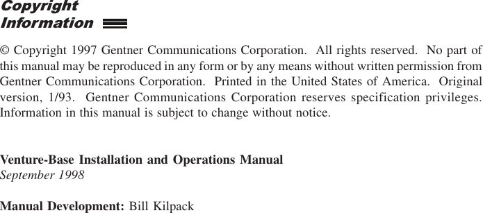

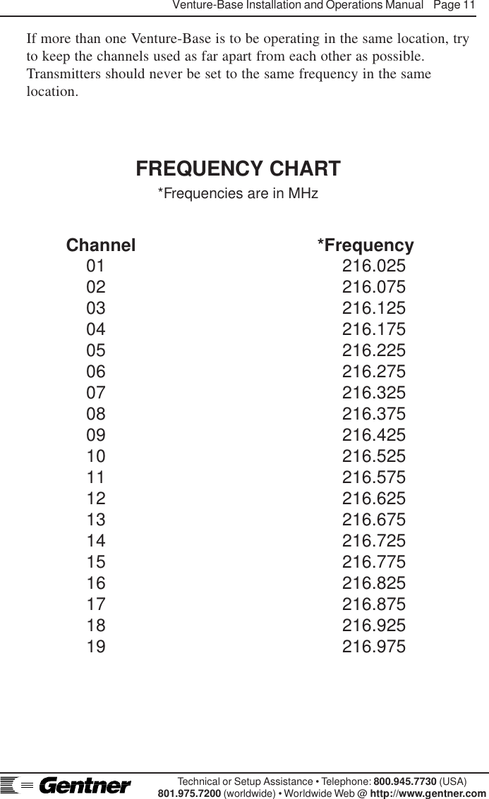
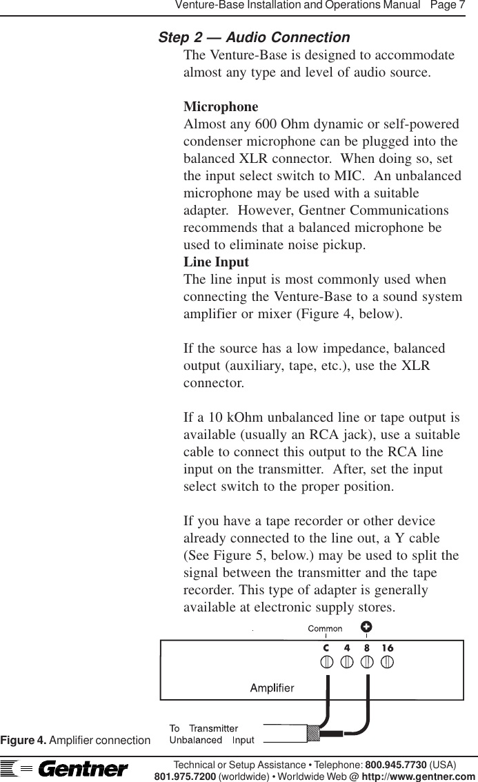
![Venture-Base Installation and Operations Manual Page 3Technical or Setup Assistance • Telephone: 800.945.7730 (USA)801.975.7200 (worldwide) • Worldwide Web @ http://www.gentner.comSeveral accessory options are available includingreceivers, headphones, battery rechargers, portabletransmitter, etc., to fit your needs. Contact GentnerCommunications or your dealer for information.The Venture-Base was designed for ease inoperation. The Venture-Base front-panel controls(See Figure 1, below.) perform the followingfunctions:1. Power LED. This LED lights when power isapplied.2. Power Button. This push-on/push-off buttonturns the Venture-Base ON/OFF.3. Audio Level LEDs. These three LEDs indicatethe incoming audio level:• Amber=Low• Green=Normal (occasional red flashes, 5–10percent, acceptable• Solid Red=High.4. Audio Input Level. This control adjusts theaudio-input level. To set, slowly turn up the control(with audio playing) while monitoring the LEDindicators [3], until the green LED is lit 90–95percent of the time (red LED flashing occasionally,5–10 percent).5. Process. This control sets the overallcompression level. Set it wherever the effect is mostpleasing (typically at 10 o’clock).6. In. This push-on/push-pff button activates/deactivates the Aphex Aural Exciter process. Thisenhancement can be switched in and out.AccessoriesFront PanelControlsFigure 1. Venture-Base front panel controls](https://usermanual.wiki/ClearOne/VB402051.Complete-Users-Manual/User-Guide-14939-Page-8.png)
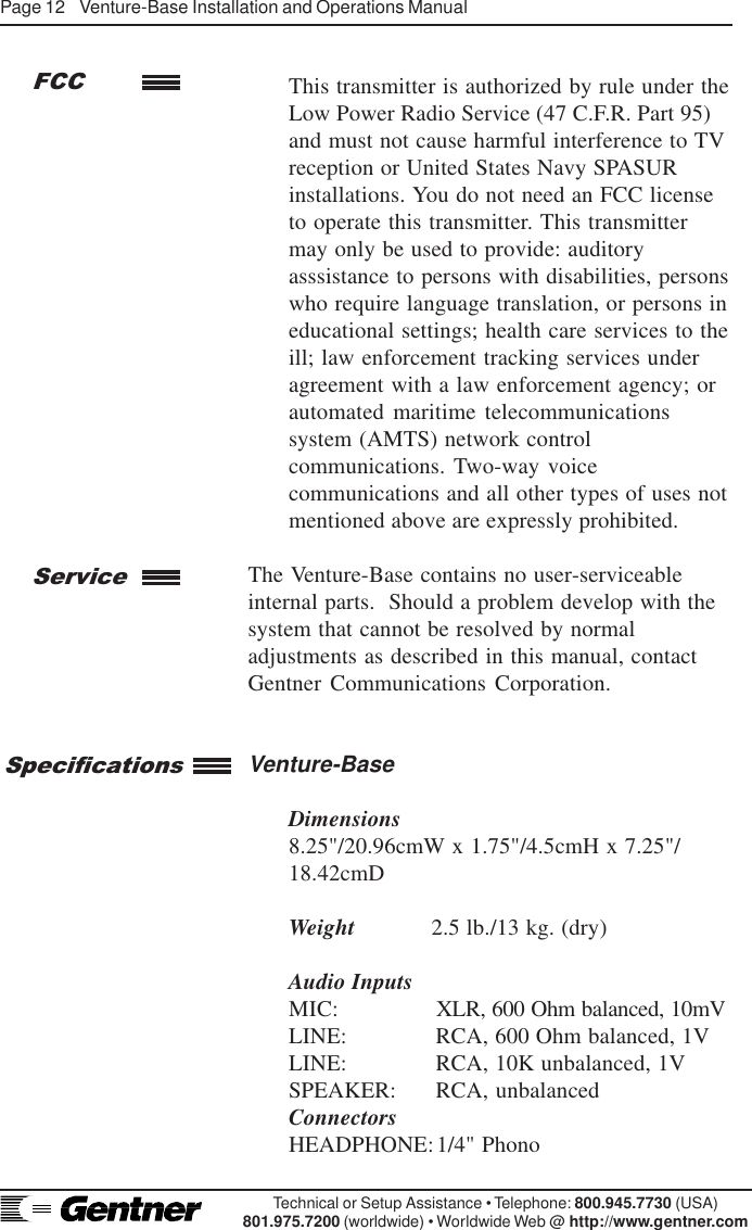
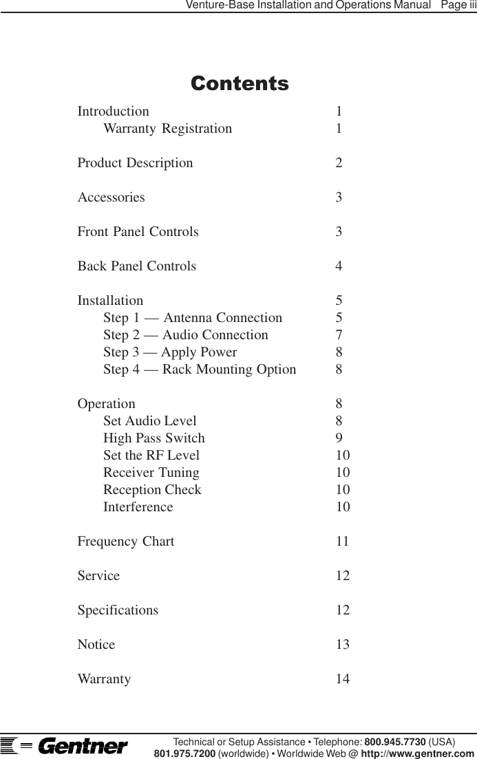
![Page 4 Venture-Base Installation and Operations ManualTechnical or Setup Assistance • Telephone: 800.945.7730 (USA)801.975.7200 (worldwide) • Worldwide Web @ http://www.gentner.com7. Monitor Level. This control sets the level of theaudio at the jack [8].8. . This headphone jack provides easymonitoring of transmitter operation. Its output is1W, capable of driving most headphones.HEADPHONE NOTE:Ensure that the headphone jack does not makemetal contact with the face place of the Venture-Base.9. RF. This LED indicates proper RF-circuitfunction to simplify system troubleshooting (i.e. nosignal being received). When lit, the LED indicatesRF signal presence.The Venture-Base’s back-panel connectors andcontrols (See Figure 2, below.) are designed forease in use.Front PanelContinuedBack PanelControls1. Antenna. This 50 Ohm output is for connectionof the supplied local antenna or the remote antenna(see Step 1, Page 6). Do not operate thetransmitter without the antenna.2. RF Level. This switch sets the RF output to one-quarter, half or full power to control the amount ofcoverage and to reduce the chance of interference.3. RF Channel Switch. RF channels can bechanged by setting the thumbwheel to any channelfrom 01–19. The corresponding frequencies areindicated on the top of the transmitter. If set otherthan 01–19, the system defaults to channel 01.Figure 2. TX-37A back panel controls](https://usermanual.wiki/ClearOne/VB402051.Complete-Users-Manual/User-Guide-14939-Page-9.png)
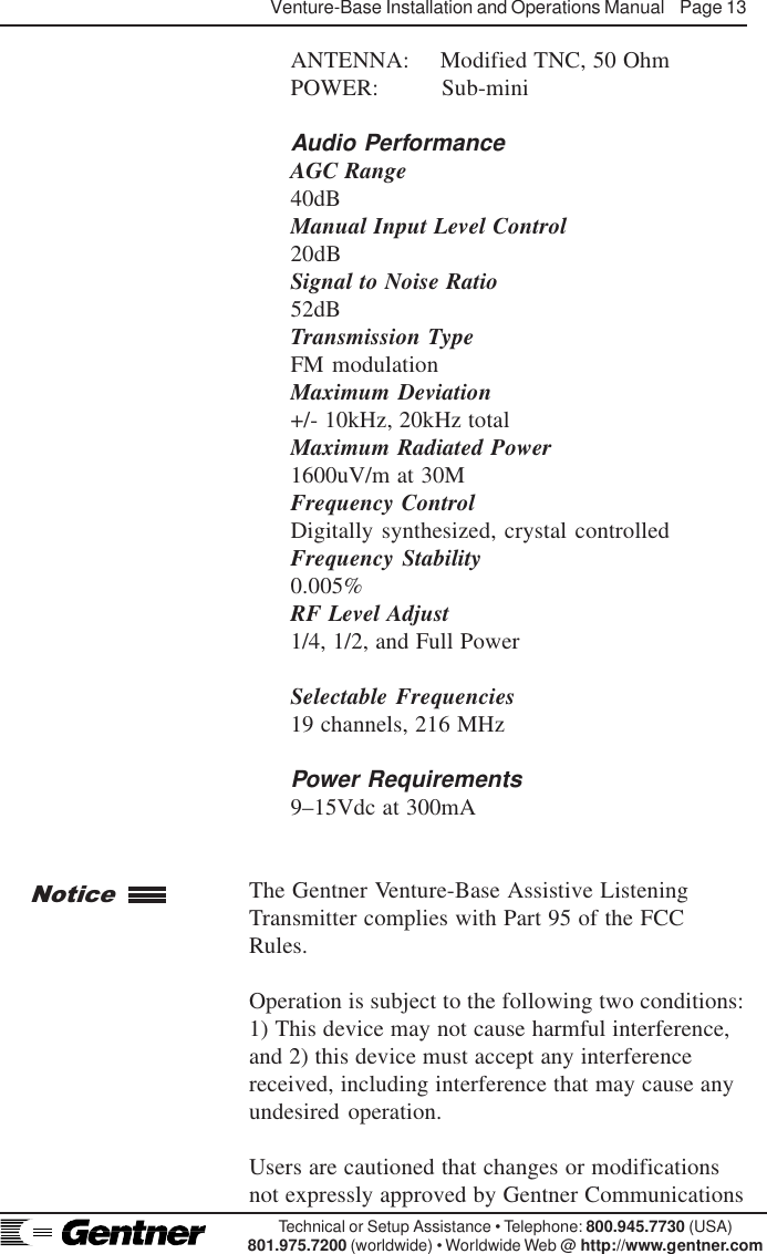
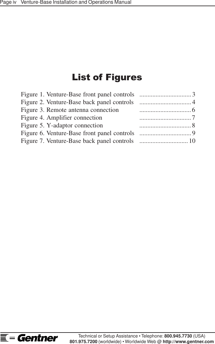
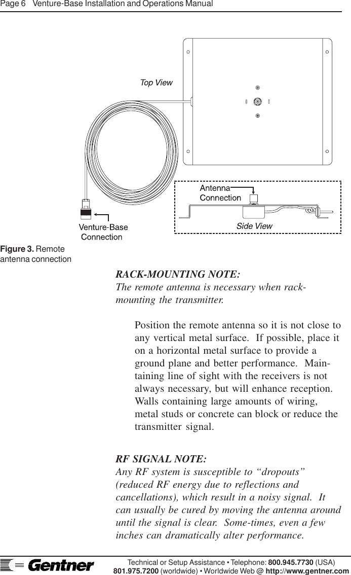
![Venture-Base Installation and Operations Manual Page 5Technical or Setup Assistance • Telephone: 800.945.7730 (USA)801.975.7200 (worldwide) • Worldwide Web @ http://www.gentner.com4. Tone. This switch sends a 40Hz test tonethrough the audio circuit to test the transmitter andaid in tuning receivers. To tune receivers, set thetransmitter to the desired operating channel,activate the tone, then tune the receiver for clearestreception. (Refer to receiver user’s guide.)5. Hi Pass. This switch activates the high-passfilter, which rolls off low frequencies below 180Hz(i.e., wind noise and room reverberation). Theselow frequencies are not needed for voiceintelligibility.6. Unbalanced. This unbalanced RCA audio inputjack is a 10 kOhm input intended for connection ofunbalanced signals from line/speaker-level outputs.7. Input Select. This screwdriver-set control selectsthe input source from balanced mic and line-levelsignals to unbalanced line and speaker-level signals.8. Ballanced Input. The balanced audio input XLRconnector is 600 Ohms, transformer balanced, forbalanced mic and line level-input signals.9. Power. The Venture-Base requires 11–15Vdca500mA, supplied by the provided AC powersupply, or by other sources (batteries, auto cigarettelighter).The Venture-Base is designed for easy installationand setup. To install the Venture-Base, follow thesestep-by-step instructions:Step 1 — Antenna ConnectionAttach the provided rubber whip antenna to themodified TNC connector [1] (Figure 2, Page 4).It may be installed directly on the rear of theVenture-Base, or remotely mounted on thesupplied antenna mount and 49-foot cable(Figure 3, below).Unless the transmitter is used in a very smallroom, best performance is with the remoteantenna placed away from the Venture-Base,but as close to the receiver(s) as possible.Installation](https://usermanual.wiki/ClearOne/VB402051.Complete-Users-Manual/User-Guide-14939-Page-10.png)
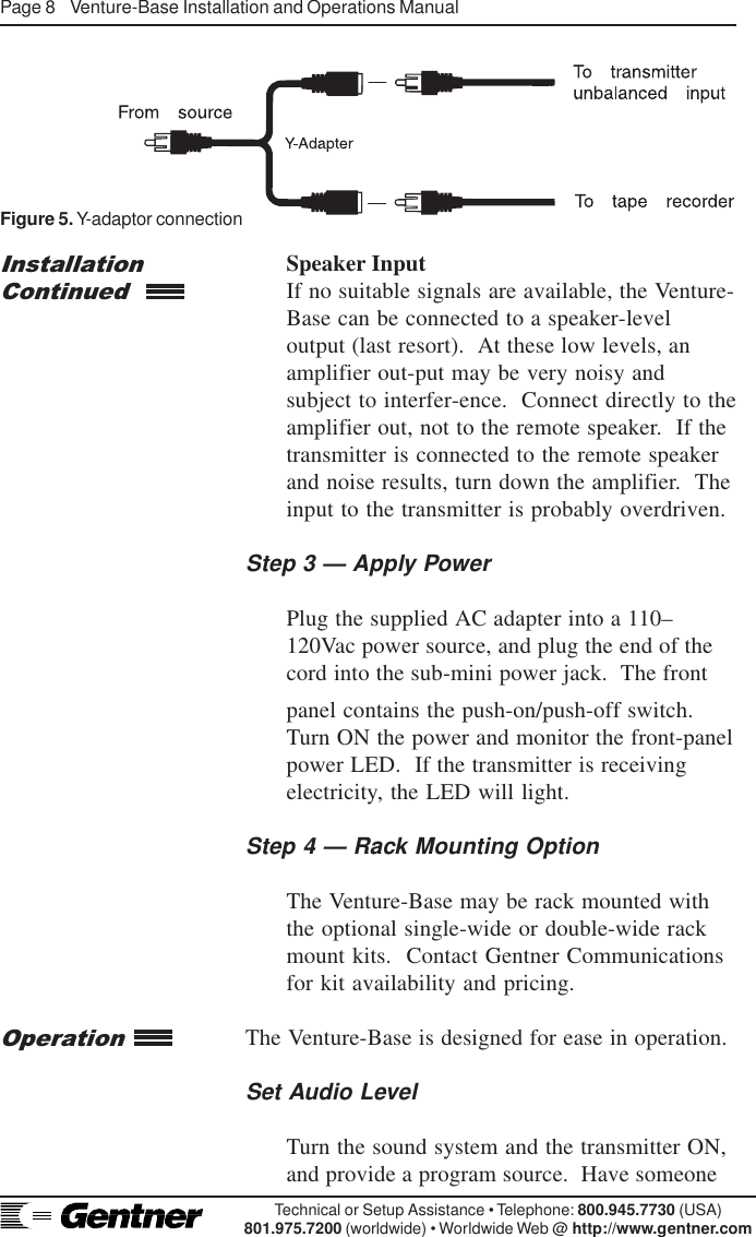
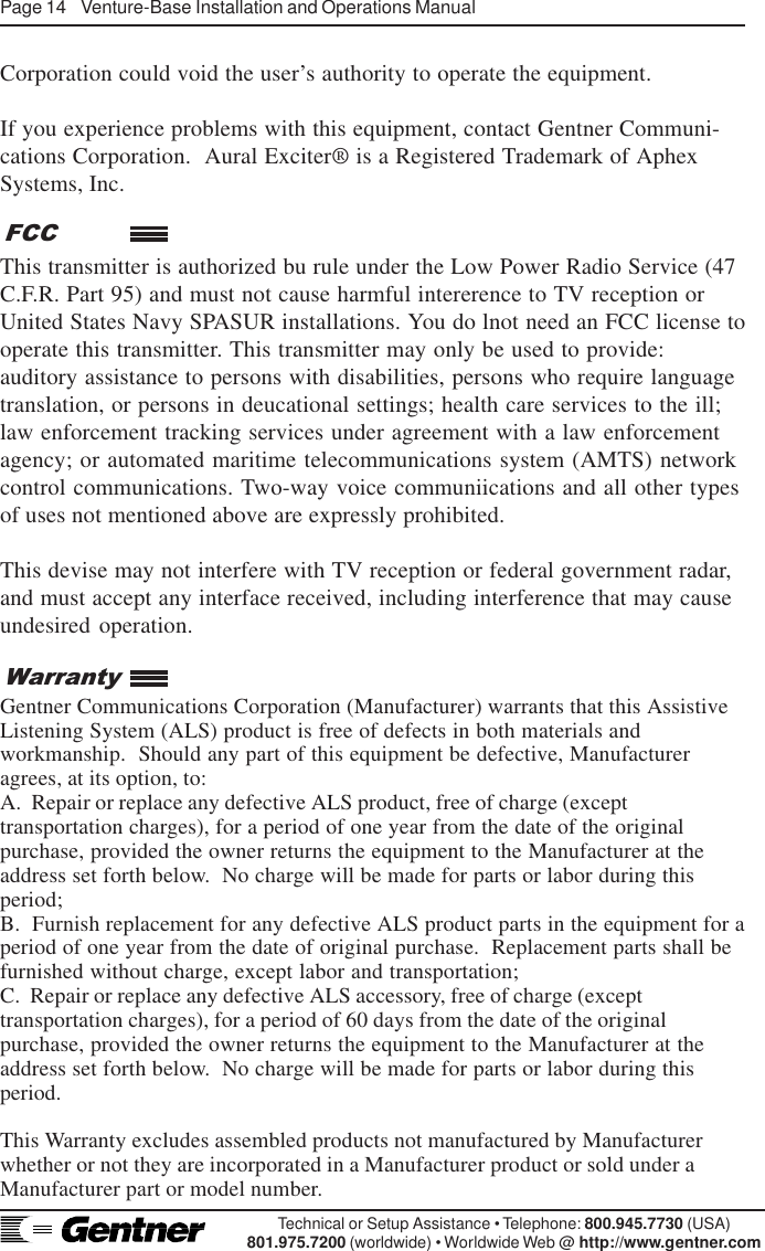
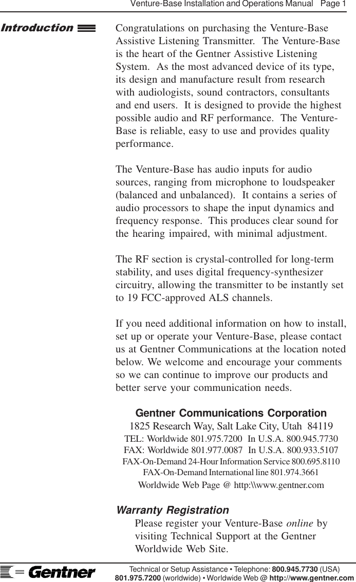
![Venture-Base Installation and Operations Manual Page 9Technical or Setup Assistance • Telephone: 800.945.7730 (USA)801.975.7200 (worldwide) • Worldwide Web @ http://www.gentner.comspeak into the microphone or connect an audiosource to the sound system. Slowly raise theAUDIO INPUT LEVEL control [4] (See Figure6, below.) until the amber and green LEDs areON, and the red LED flashes 5–10 percent [3].The AUDIO INPUT LEVEL control [4] istypically set between 9 and 3 o’clock. If theinput cannot be set easily with the front panelcontrol, try setting the input select switch onthe back panel to a higher or lower setting, orchange the output level of your source device.High Pass SwitchIf the system is to be used primarily with voiceFigure 6. Venture-Base front panel controlstransmission, set the back panel HI PASSswitch [5] to ON (Figure 7, below). This willcut low frequencies below 180Hz, reducingreverberation.Figure 7. Venture-Base back panel controls](https://usermanual.wiki/ClearOne/VB402051.Complete-Users-Manual/User-Guide-14939-Page-14.png)
![Page 10 Venture-Base Installation and Operations ManualTechnical or Setup Assistance • Telephone: 800.945.7730 (USA)801.975.7200 (worldwide) • Worldwide Web @ http://www.gentner.comSet the RF LevelTransmitters must never be set to the samefrequency in the same location. Channels mustbe set as far apart from each other as possible.Test the reception with the RF level at one-halfor one-quarter [2] power. The lower it can beoperated satisfactorily, the less chance thereOperationContinuedwill be for interference with another system.One-half or one-quarter power should covermost classroom applications.Receiver TuningSet the TONE switch [4] to ON. To tune thereceiver, refer to the respective receiver user’sguide.Reception CheckUsing the tone or other audio source, walkaround with the receiver. Verify the re-ceptionin all parts of the room. If reception is notoptimal, move the transmitter antenna toanother location and repeat this procedure.InterferenceWith any type of RF device, other RF sourcescan interfere with reception. Even the FCC-designated ALS band is occasionally subject touse by other types of devices.Interference can take the form of rising-and-falling audio. To verify on-channelinterference, take the receiver to the placewhere the interference is worst and turn off thetransmitter. The interfering signal should nowcome in stronger. Since the Venture-Base isfrequency-agile, you can set it to anotherchannel and retune the receivers to move awayfrom the interference.](https://usermanual.wiki/ClearOne/VB402051.Complete-Users-Manual/User-Guide-14939-Page-15.png)