ClearOne VB402051 Auditory Assistance Listening Device User Manual venture base cvr p65
ClearOne, Inc. Auditory Assistance Listening Device venture base cvr p65
ClearOne >
Contents
- 1. Compliance Statement
- 2. Complete Users Manual
Complete Users Manual

Installation and
Operations Manual
Venture-Base Transmitter
Gentner Communications Corporation
Assistive Listening Systems

© Copyright 1997 Gentner Communications Corporation. All rights reserved. No part of
this manual may be reproduced in any form or by any means without written permission from
Gentner Communications Corporation. Printed in the United States of America. Original
version, 1/93. Gentner Communications Corporation reserves specification privileges.
Information in this manual is subject to change without notice.
Venture-Base Installation and Operations Manual
September 1998
Manual Development: Bill Kilpack
Copyright
Information

Venture-Base Transmitter
Installation and
Operations Manual

Venture-Base Installation and Operations Manual Page iii
Technical or Setup Assistance • Telephone: 800.945.7730 (USA)
801.975.7200 (worldwide) • Worldwide Web @ http://www.gentner.com
Introduction 1
Warranty Registration 1
Product Description 2
Accessories 3
Front Panel Controls 3
Back Panel Controls 4
Installation 5
Step 1 — Antenna Connection 5
Step 2 — Audio Connection 7
Step 3 — Apply Power 8
Step 4 — Rack Mounting Option 8
Operation 8
Set Audio Level 8
High Pass Switch 9
Set the RF Level 10
Receiver Tuning 10
Reception Check 10
Interference 10
Frequency Chart 11
Service 12
Specifications 12
Notice 13
Warranty 14
Contents

Page iv Venture-Base Installation and Operations Manual
Technical or Setup Assistance • Telephone: 800.945.7730 (USA)
801.975.7200 (worldwide) • Worldwide Web @ http://www.gentner.com
List of Figures
Figure 1. Venture-Base front panel controls ................................3
Figure 2. Venture-Base back panel controls ................................4
Figure 3. Remote antenna connection ................................6
Figure 4. Amplifier connection ................................7
Figure 5. Y-adaptor connection ................................8
Figure 6. Venture-Base front panel controls ................................9
Figure 7. Venture-Base back panel controls ..............................10

Venture-Base Installation and Operations Manual Page 1
Technical or Setup Assistance • Telephone: 800.945.7730 (USA)
801.975.7200 (worldwide) • Worldwide Web @ http://www.gentner.com
Congratulations on purchasing the Venture-Base
Assistive Listening Transmitter. The Venture-Base
is the heart of the Gentner Assistive Listening
System. As the most advanced device of its type,
its design and manufacture result from research
with audiologists, sound contractors, consultants
and end users. It is designed to provide the highest
possible audio and RF performance. The Venture-
Base is reliable, easy to use and provides quality
performance.
The Venture-Base has audio inputs for audio
sources, ranging from microphone to loudspeaker
(balanced and unbalanced). It contains a series of
audio processors to shape the input dynamics and
frequency response. This produces clear sound for
the hearing impaired, with minimal adjustment.
The RF section is crystal-controlled for long-term
stability, and uses digital frequency-synthesizer
circuitry, allowing the transmitter to be instantly set
to 19 FCC-approved ALS channels.
If you need additional information on how to install,
set up or operate your Venture-Base, please contact
us at Gentner Communications at the location noted
below. We welcome and encourage your comments
so we can continue to improve our products and
better serve your communication needs.
Gentner Communications Corporation
1825 Research Way, Salt Lake City, Utah 84119
TEL: Worldwide 801.975.7200 In U.S.A. 800.945.7730
FAX: Worldwide 801.977.0087 In U.S.A. 800.933.5107
FAX-On-Demand 24-Hour Information Service 800.695.8110
FAX-On-Demand International line 801.974.3661
Worldwide Web Page @ http:\\www.gentner.com
Warranty Registration
Please register your Venture-Base online by
visiting Technical Support at the Gentner
Worldwide Web Site.
Introduction

Page 2 Venture-Base Installation and Operations Manual
Technical or Setup Assistance • Telephone: 800.945.7730 (USA)
801.975.7200 (worldwide) • Worldwide Web @ http://www.gentner.com
Making sound clearer for the hearing impaired
requires more than just making it louder. The needs
of the hearing impaired differ from those with
normal hearing. Audio processing is needed to
reshape the sound. The most common impairments
are reduced sensitivity and dynamic range, and loss
of high frequencies. Many of the audio sources
have extremely high dynamic range — often
difficult to hear under optimal circumstances.
The Venture Base’s audio processing is similar to
that used at a commercial radio station. Automatic
gain control (AGC) controls the long-term levels,
equalizing different types of program material.
This compensates for variations in level. The
audio is tied to the AGC circuit, so incoming audio
is always controlled, greatly reducing distortion.
Audio passes through a split-band compressor,
reducing the signal’s dynamics, making the sound
not only louder but more intelligible. Normally,
available compression is very limited, since too
much compression creates a dull, muffled sound.
To prevent this, the Venture-Base splits the audio
into high and low bands. It then processes them
separately, so each band receives the correct
amount of compression. This allows more
compression overall, amplifying sound without
dullness — and without noticing the compression.
After compression, the sound is fed to the patented
Aphex Aural Exciter® circuit. This process has
been used in the recording and broadcast industries
for decades. Aphex processing creates an increase
in perceived brightness for the listener. A final
signal limiter is used to provide an absolute audio
peak level so the FM signal can never be over-
modulated (which causes distortion).
People with or without hearing impairment
appreciate this sophisticated processing, with its
clear sound and improved intelligibility.
Product
Description
Venture-Base Installation and Operations Manual Page 3
Technical or Setup Assistance • Telephone: 800.945.7730 (USA)
801.975.7200 (worldwide) • Worldwide Web @ http://www.gentner.com
Several accessory options are available including
receivers, headphones, battery rechargers, portable
transmitter, etc., to fit your needs. Contact Gentner
Communications or your dealer for information.
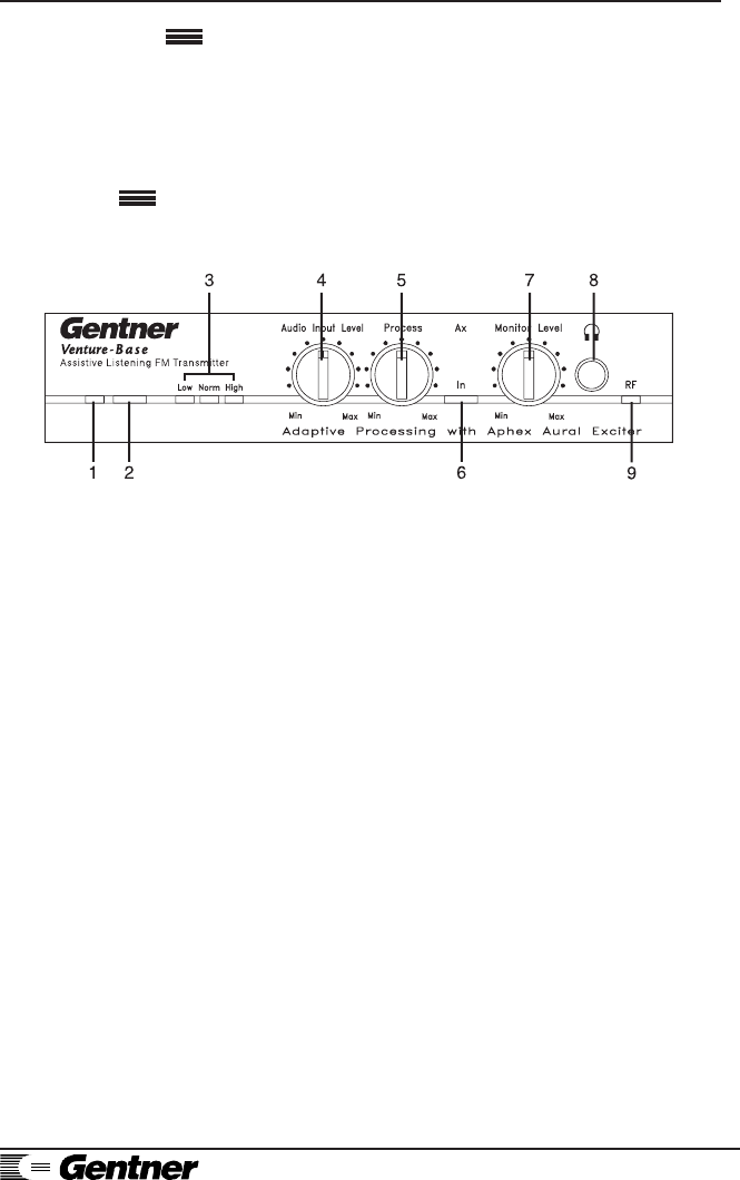
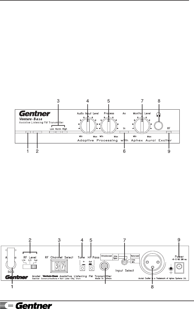
The Venture-Base was designed for ease in
operation. The Venture-Base front-panel controls
(See Figure 1, below.) perform the following
functions:
1. Power LED. This LED lights when power is
applied.
2. Power Button. This push-on/push-off button
turns the Venture-Base ON/OFF.
3. Audio Level LEDs. These three LEDs indicate
the incoming audio level:
• Amber=Low
• Green=Normal (occasional red flashes, 5–10
percent, acceptable
• Solid Red=High.
4. Audio Input Level. This control adjusts the
audio-input level. To set, slowly turn up the control
(with audio playing) while monitoring the LED
indicators [3], until the green LED is lit 90–95
percent of the time (red LED flashing occasionally,
5–10 percent).
5. Process. This control sets the overall
compression level. Set it wherever the effect is most
pleasing (typically at 10 o’clock).
6. In. This push-on/push-pff button activates/
deactivates the Aphex Aural Exciter process. This
enhancement can be switched in and out.
Accessories
Front Panel
Controls
Figure 1. Venture-Base front panel controls
Page 4 Venture-Base Installation and Operations Manual
Technical or Setup Assistance • Telephone: 800.945.7730 (USA)
801.975.7200 (worldwide) • Worldwide Web @ http://www.gentner.com
7. Monitor Level. This control sets the level of the
audio at the jack [8].
8. . This headphone jack provides easy
monitoring of transmitter operation. Its output is
1W, capable of driving most headphones.
HEADPHONE NOTE:
Ensure that the headphone jack does not make
metal contact with the face place of the Venture-
Base.
9. RF. This LED indicates proper RF-circuit
function to simplify system troubleshooting (i.e. no
signal being received). When lit, the LED indicates
RF signal presence.
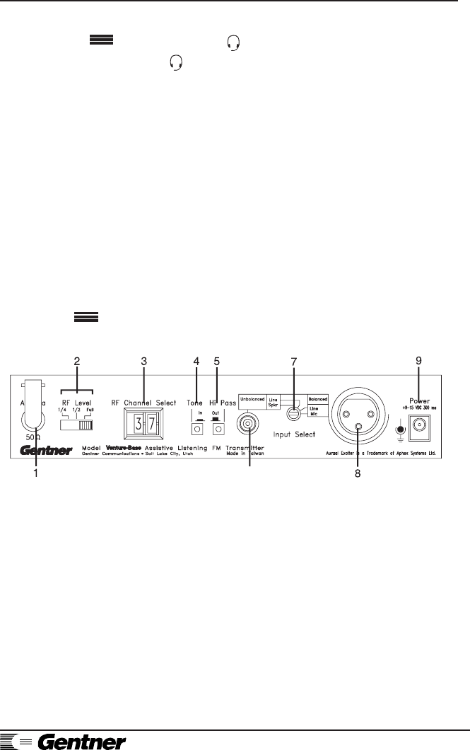
The Venture-Base’s back-panel connectors and
controls (See Figure 2, below.) are designed for
ease in use.
Front Panel
Continued
Back Panel
Controls
1. Antenna. This 50 Ohm output is for connection
of the supplied local antenna or the remote antenna
(see Step 1, Page 6). Do not operate the
transmitter without the antenna.
2. RF Level. This switch sets the RF output to one-
quarter, half or full power to control the amount of
coverage and to reduce the chance of interference.
3. RF Channel Switch. RF channels can be
changed by setting the thumbwheel to any channel
from 01–19. The corresponding frequencies are
indicated on the top of the transmitter. If set other
than 01–19, the system defaults to channel 01.
Figure 2. TX-37A back panel controls

Venture-Base Installation and Operations Manual Page 5
Technical or Setup Assistance • Telephone: 800.945.7730 (USA)
801.975.7200 (worldwide) • Worldwide Web @ http://www.gentner.com
4. Tone. This switch sends a 40Hz test tone
through the audio circuit to test the transmitter and
aid in tuning receivers. To tune receivers, set the
transmitter to the desired operating channel,
activate the tone, then tune the receiver for clearest
reception. (Refer to receiver user’s guide.)
5. Hi Pass. This switch activates the high-pass
filter, which rolls off low frequencies below 180Hz
(i.e., wind noise and room reverberation). These
low frequencies are not needed for voice
intelligibility.
6. Unbalanced. This unbalanced RCA audio input
jack is a 10 kOhm input intended for connection of
unbalanced signals from line/speaker-level outputs.
7. Input Select. This screwdriver-set control selects
the input source from balanced mic and line-level
signals to unbalanced line and speaker-level signals.
8. Ballanced Input. The balanced audio input XLR
connector is 600 Ohms, transformer balanced, for
balanced mic and line level-input signals.
9. Power. The Venture-Base requires 11–15Vdc
a500mA, supplied by the provided AC power
supply, or by other sources (batteries, auto cigarette
lighter).
The Venture-Base is designed for easy installation
and setup. To install the Venture-Base, follow these
step-by-step instructions:
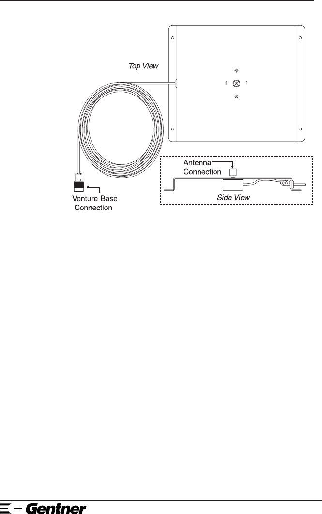
Step 1 — Antenna Connection
Attach the provided rubber whip antenna to the
modified TNC connector [1] (Figure 2, Page 4).
It may be installed directly on the rear of the
Venture-Base, or remotely mounted on the
supplied antenna mount and 49-foot cable
(Figure 3, below).
Unless the transmitter is used in a very small
room, best performance is with the remote
antenna placed away from the Venture-Base,
but as close to the receiver(s) as possible.
Installation
Page 6 Venture-Base Installation and Operations Manual
Technical or Setup Assistance • Telephone: 800.945.7730 (USA)
801.975.7200 (worldwide) • Worldwide Web @ http://www.gentner.com
RACK-MOUNTING NOTE:
The remote antenna is necessary when rack-
mounting the transmitter.
Position the remote antenna so it is not close to
any vertical metal surface. If possible, place it
on a horizontal metal surface to provide a
ground plane and better performance. Main-
taining line of sight with the receivers is not
always necessary, but will enhance reception.
Walls containing large amounts of wiring,
metal studs or concrete can block or reduce the
transmitter signal.
Figure 3. Remote
antenna connection
RF SIGNAL NOTE:
Any RF system is susceptible to “dropouts”
(reduced RF energy due to reflections and
cancellations), which result in a noisy signal. It
can usually be cured by moving the antenna around
until the signal is clear. Some-times, even a few
inches can dramatically alter performance.
Venture-Base Installation and Operations Manual Page 7
Technical or Setup Assistance • Telephone: 800.945.7730 (USA)
801.975.7200 (worldwide) • Worldwide Web @ http://www.gentner.com
Step 2 — Audio Connection
The Venture-Base is designed to accommodate
almost any type and level of audio source.
Microphone
Almost any 600 Ohm dynamic or self-powered
condenser microphone can be plugged into the
balanced XLR connector. When doing so, set
the input select switch to MIC. An unbalanced
microphone may be used with a suitable
adapter. However, Gentner Communications
recommends that a balanced microphone be
used to eliminate noise pickup.
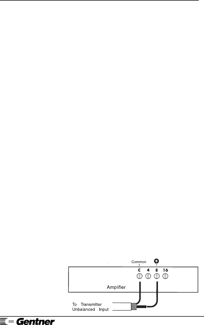
Line Input
The line input is most commonly used when
connecting the Venture-Base to a sound system
amplifier or mixer (Figure 4, below).
If the source has a low impedance, balanced
output (auxiliary, tape, etc.), use the XLR
connector.
If a 10 kOhm unbalanced line or tape output is
available (usually an RCA jack), use a suitable
cable to connect this output to the RCA line
input on the transmitter. After, set the input
select switch to the proper position.
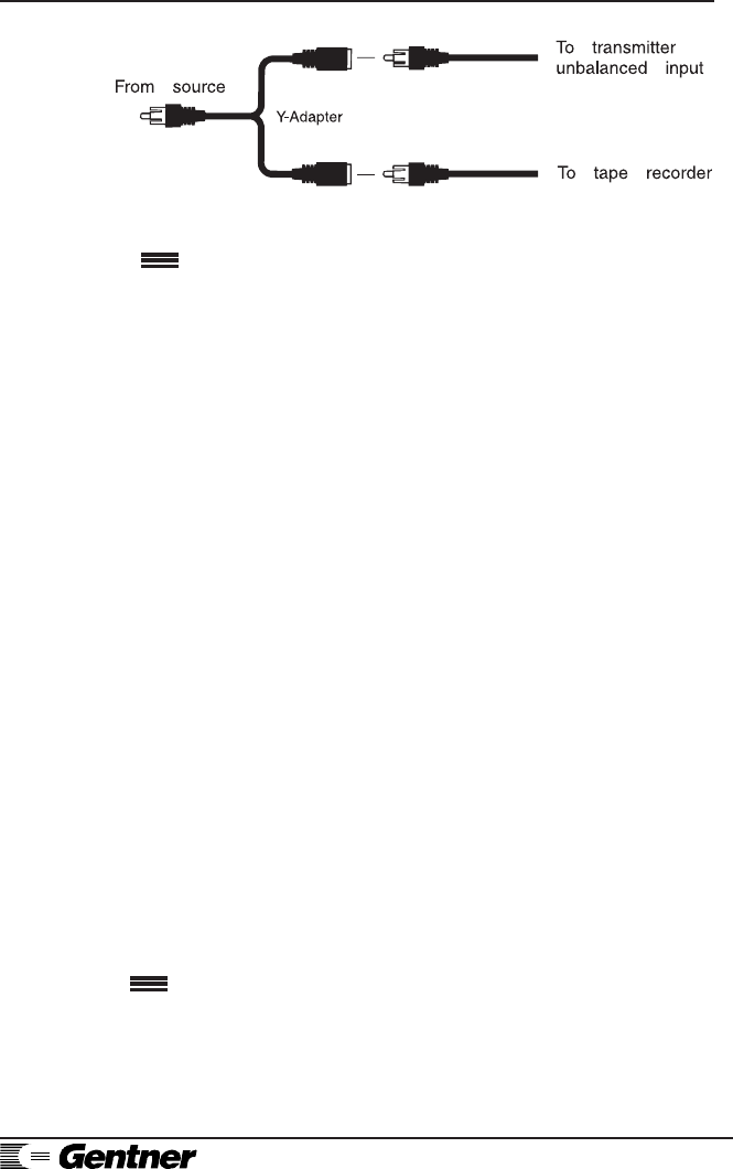
If you have a tape recorder or other device
already connected to the line out, a Y cable
(See Figure 5, below.) may be used to split the
signal between the transmitter and the tape
recorder. This type of adapter is generally
available at electronic supply stores.
Figure 4. Amplifier connection
Page 8 Venture-Base Installation and Operations Manual
Technical or Setup Assistance • Telephone: 800.945.7730 (USA)
801.975.7200 (worldwide) • Worldwide Web @ http://www.gentner.com
Operation
Speaker Input
If no suitable signals are available, the Venture-
Base can be connected to a speaker-level
output (last resort). At these low levels, an
amplifier out-put may be very noisy and
subject to interfer-ence. Connect directly to the
amplifier out, not to the remote speaker. If the
transmitter is connected to the remote speaker
and noise results, turn down the amplifier. The
input to the transmitter is probably overdriven.
Step 3 — Apply Power
Plug the supplied AC adapter into a 110–
120Vac power source, and plug the end of the
cord into the sub-mini power jack. The front
Installation
Continued
Figure 5. Y-adaptor connection
panel contains the push-on/push-off switch.
Turn ON the power and monitor the front-panel
power LED. If the transmitter is receiving
electricity, the LED will light.
Step 4 — Rack Mounting Option
The Venture-Base may be rack mounted with
the optional single-wide or double-wide rack
mount kits. Contact Gentner Communications
for kit availability and pricing.
The Venture-Base is designed for ease in operation.
Set Audio Level
Turn the sound system and the transmitter ON,
and provide a program source. Have someone
Venture-Base Installation and Operations Manual Page 9
Technical or Setup Assistance • Telephone: 800.945.7730 (USA)
801.975.7200 (worldwide) • Worldwide Web @ http://www.gentner.com
speak into the microphone or connect an audio
source to the sound system. Slowly raise the
AUDIO INPUT LEVEL control [4] (See Figure
6, below.) until the amber and green LEDs are
ON, and the red LED flashes 5–10 percent [3].
The AUDIO INPUT LEVEL control [4] is
typically set between 9 and 3 o’clock. If the
input cannot be set easily with the front panel
control, try setting the input select switch on
the back panel to a higher or lower setting, or
change the output level of your source device.
High Pass Switch
If the system is to be used primarily with voice
Figure 6. Venture-Base front panel controls
transmission, set the back panel HI PASS
switch [5] to ON (Figure 7, below). This will
cut low frequencies below 180Hz, reducing
reverberation.
Figure 7. Venture-Base back panel controls

Page 10 Venture-Base Installation and Operations Manual
Technical or Setup Assistance • Telephone: 800.945.7730 (USA)
801.975.7200 (worldwide) • Worldwide Web @ http://www.gentner.com
Set the RF Level
Transmitters must never be set to the same
frequency in the same location. Channels must
be set as far apart from each other as possible.
Test the reception with the RF level at one-half
or one-quarter [2] power. The lower it can be
operated satisfactorily, the less chance there
Operation
Continued
will be for interference with another system.
One-half or one-quarter power should cover
most classroom applications.
Receiver Tuning
Set the TONE switch [4] to ON. To tune the
receiver, refer to the respective receiver user’s
guide.
Reception Check
Using the tone or other audio source, walk
around with the receiver. Verify the re-ception
in all parts of the room. If reception is not
optimal, move the transmitter antenna to
another location and repeat this procedure.
Interference
With any type of RF device, other RF sources
can interfere with reception. Even the FCC-
designated ALS band is occasionally subject to
use by other types of devices.
Interference can take the form of rising-and-
falling audio. To verify on-channel
interference, take the receiver to the place
where the interference is worst and turn off the
transmitter. The interfering signal should now
come in stronger. Since the Venture-Base is
frequency-agile, you can set it to another
channel and retune the receivers to move away
from the interference.

Venture-Base Installation and Operations Manual Page 11
Technical or Setup Assistance • Telephone: 800.945.7730 (USA)
801.975.7200 (worldwide) • Worldwide Web @ http://www.gentner.com
FREQUENCY CHART
*Frequencies are in MHz
Channel *Frequency
01 216.025
02 216.075
03 216.125
04 216.175
05 216.225
06 216.275
07 216.325
08 216.375
09 216.425
10 216.525
11 216.575
12 216.625
13 216.675
14 216.725
15 216.775
16 216.825
17 216.875
18 216.925
19 216.975
If more than one Venture-Base is to be operating in the same location, try
to keep the channels used as far apart from each other as possible.
Transmitters should never be set to the same frequency in the same
location.

Page 12 Venture-Base Installation and Operations Manual
Technical or Setup Assistance • Telephone: 800.945.7730 (USA)
801.975.7200 (worldwide) • Worldwide Web @ http://www.gentner.com
This transmitter is authorized by rule under the
Low Power Radio Service (47 C.F.R. Part 95)
and must not cause harmful interference to TV
reception or United States Navy SPASUR
installations. You do not need an FCC license
to operate this transmitter. This transmitter
may only be used to provide: auditory
asssistance to persons with disabilities, persons
who require language translation, or persons in
educational settings; health care services to the
ill; law enforcement tracking services under
agreement with a law enforcement agency; or
automated maritime telecommunications
system (AMTS) network control
communications. Two-way voice
communications and all other types of uses not
mentioned above are expressly prohibited.
The Venture-Base contains no user-serviceable
internal parts. Should a problem develop with the
system that cannot be resolved by normal
adjustments as described in this manual, contact
Gentner Communications Corporation.
Venture-Base
Dimensions
8.25"/20.96cmW x 1.75"/4.5cmH x 7.25"/
18.42cmD
Weight 2.5 lb./13 kg. (dry)
Audio Inputs
MIC: XLR, 600 Ohm balanced, 10mV
LINE: RCA, 600 Ohm balanced, 1V
LINE: RCA, 10K unbalanced, 1V
SPEAKER: RCA, unbalanced
Connectors
HEADPHONE:1/4" Phono
Service
FCC
Specifications

Venture-Base Installation and Operations Manual Page 13
Technical or Setup Assistance • Telephone: 800.945.7730 (USA)
801.975.7200 (worldwide) • Worldwide Web @ http://www.gentner.com
ANTENNA: Modified TNC, 50 Ohm
POWER: Sub-mini
Audio Performance
AGC Range
40dB
Manual Input Level Control
20dB
Signal to Noise Ratio
52dB
Transmission Type
FM modulation
Maximum Deviation
+/- 10kHz, 20kHz total
Maximum Radiated Power
1600uV/m at 30M
Frequency Control
Digitally synthesized, crystal controlled
Frequency Stability
0.005%
RF Level Adjust
1/4, 1/2, and Full Power
Selectable Frequencies
19 channels, 216 MHz
Power Requirements
9–15Vdc at 300mA
The Gentner Venture-Base Assistive Listening
Transmitter complies with Part 95 of the FCC
Rules.
Operation is subject to the following two conditions:
1) This device may not cause harmful interference,
and 2) this device must accept any interference
received, including interference that may cause any
undesired operation.
Users are cautioned that changes or modifications
not expressly approved by Gentner Communications
Notice

Page 14 Venture-Base Installation and Operations Manual
Technical or Setup Assistance • Telephone: 800.945.7730 (USA)
801.975.7200 (worldwide) • Worldwide Web @ http://www.gentner.com
Corporation could void the user’s authority to operate the equipment.
If you experience problems with this equipment, contact Gentner Communi-
cations Corporation. Aural Exciter® is a Registered Trademark of Aphex
Systems, Inc.
This transmitter is authorized bu rule under the Low Power Radio Service (47
C.F.R. Part 95) and must not cause harmful intererence to TV reception or
United States Navy SPASUR installations. You do lnot need an FCC license to
operate this transmitter. This transmitter may only be used to provide:
auditory assistance to persons with disabilities, persons who require language
translation, or persons in deucational settings; health care services to the ill;
law enforcement tracking services under agreement with a law enforcement
agency; or automated maritime telecommunications system (AMTS) network
control communications. Two-way voice communiications and all other types
of uses not mentioned above are expressly prohibited.
This devise may not interfere with TV reception or federal government radar,
and must accept any interface received, including interference that may cause
undesired operation.
Gentner Communications Corporation (Manufacturer) warrants that this Assistive
Listening System (ALS) product is free of defects in both materials and
workmanship. Should any part of this equipment be defective, Manufacturer
agrees, at its option, to:
A. Repair or replace any defective ALS product, free of charge (except
transportation charges), for a period of one year from the date of the original
purchase, provided the owner returns the equipment to the Manufacturer at the
address set forth below. No charge will be made for parts or labor during this
period;
B. Furnish replacement for any defective ALS product parts in the equipment for a
period of one year from the date of original purchase. Replacement parts shall be
furnished without charge, except labor and transportation;
C. Repair or replace any defective ALS accessory, free of charge (except
transportation charges), for a period of 60 days from the date of the original
purchase, provided the owner returns the equipment to the Manufacturer at the
address set forth below. No charge will be made for parts or labor during this
period.
This Warranty excludes assembled products not manufactured by Manufacturer
whether or not they are incorporated in a Manufacturer product or sold under a
Manufacturer part or model number.
Warranty
FCC

Venture-Base Installation and Operations Manual Page 15
Technical or Setup Assistance • Telephone: 800.945.7730 (USA)
801.975.7200 (worldwide) • Worldwide Web @ http://www.gentner.com
THIS WARRANTY IS VOID IF:
A. The equipment has been damaged by negligence, accident, act-of-God or
mishandling, or has not been operated in accordance with the procedures described
in the operating and technical instructions; or,
B. The equipment has been altered or repaired by other than Manufacturer or an
authorized service representative of Manufacturer; or,
C. Adaptations or accessories other than those manufactured or provided by
Manufacturer have been made or attached to the equipment which, in the
determination of Manufacturer, shall have affected the performance, safety or
reliability of the equipment; or,
D. The equipment’s original serial number has been modified or removed.
NO OTHER WARRANTY, EXPRESS OR IMPLIED, INCLUDING WARRANTY
OF MERCHANTABILITY OR FITNESS FOR ANY PARTICULAR USE,
APPLIES TO THE EQUIPMENT, nor is any person or company authorized to
assume any warranty for Manufacturer or any other liability in connection with the
sale of Manufacturer’s products.
Manufacturer does not assume any responsibility for consequential damages,
expenses or loss of revenue or property, inconvenience or interruption in operation
experienced by the customer due to a malfunction in the purchased equipment. No
warranty service performed on any product shall extend the applicable warranty
period.
In case of unsatisfactory operation, the purchaser shall promptly notify
Manufacturer at the address set forth below in writing, giving full particulars as to
the defects or unsatisfactory operation, upon receipt of such notice, Manufacturer
will give instructions respecting the shipment of the equipment, or such other
matters as it elects to honor this warranty as above provided. This warranty does
not cover damage to the equipment during shipping and Manufacturer assumes no
responsibility for such damage. All shipping costs shall be paid by customer.
This warranty extends only to the original purchaser and is not assignable or
transferable.
Gentner Communications Corp., 1825 Research Way, Salt Lake City, UT 84119
Warranty
Continued