Cleveland Medical Devices 0051 Low noise 2-ch wireless data acquistion system User Manual RatPaak
Cleveland Medical Devices Inc. Low noise 2-ch wireless data acquistion system RatPaak
UserManual.wiki
>
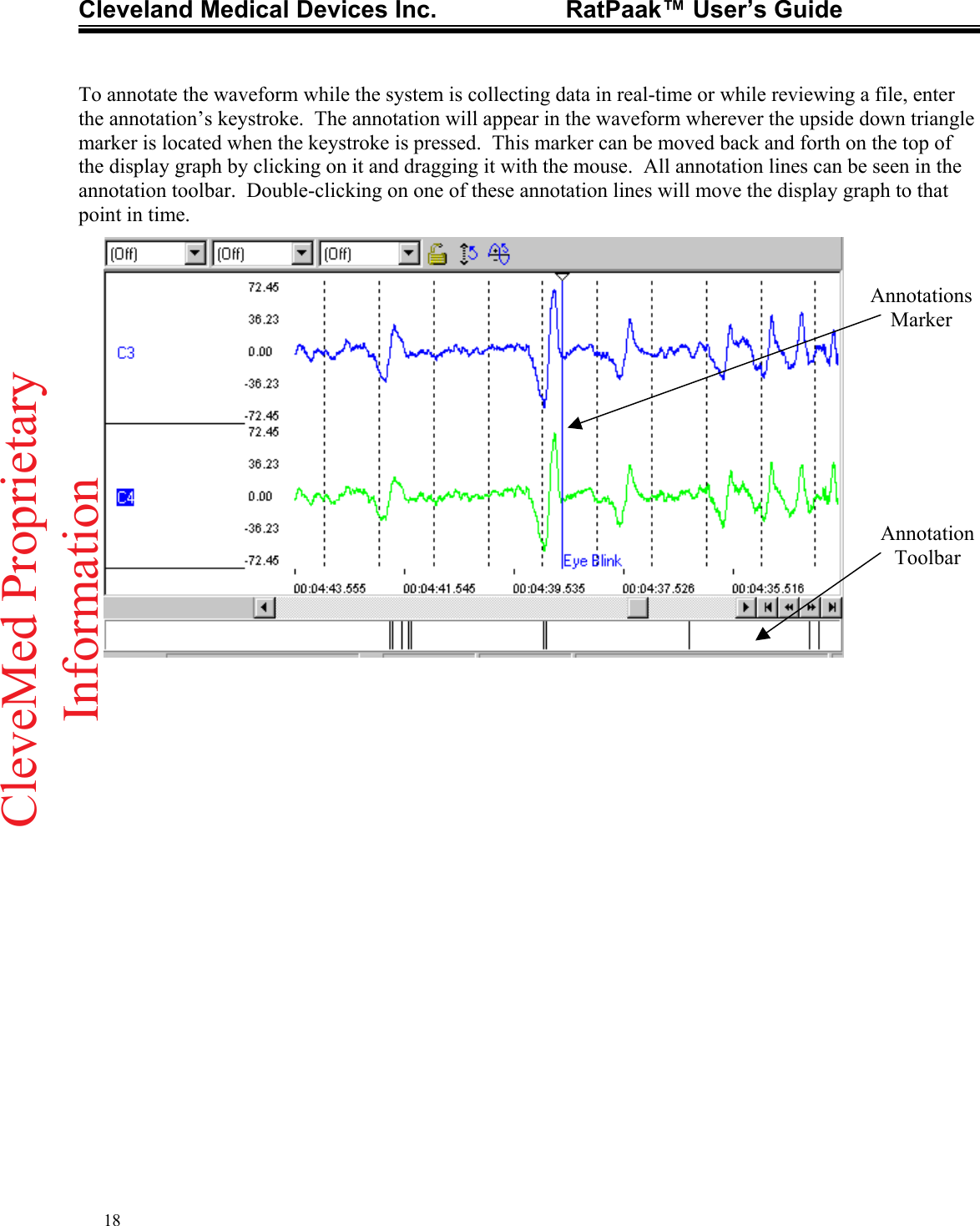
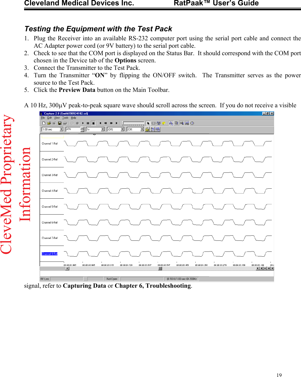
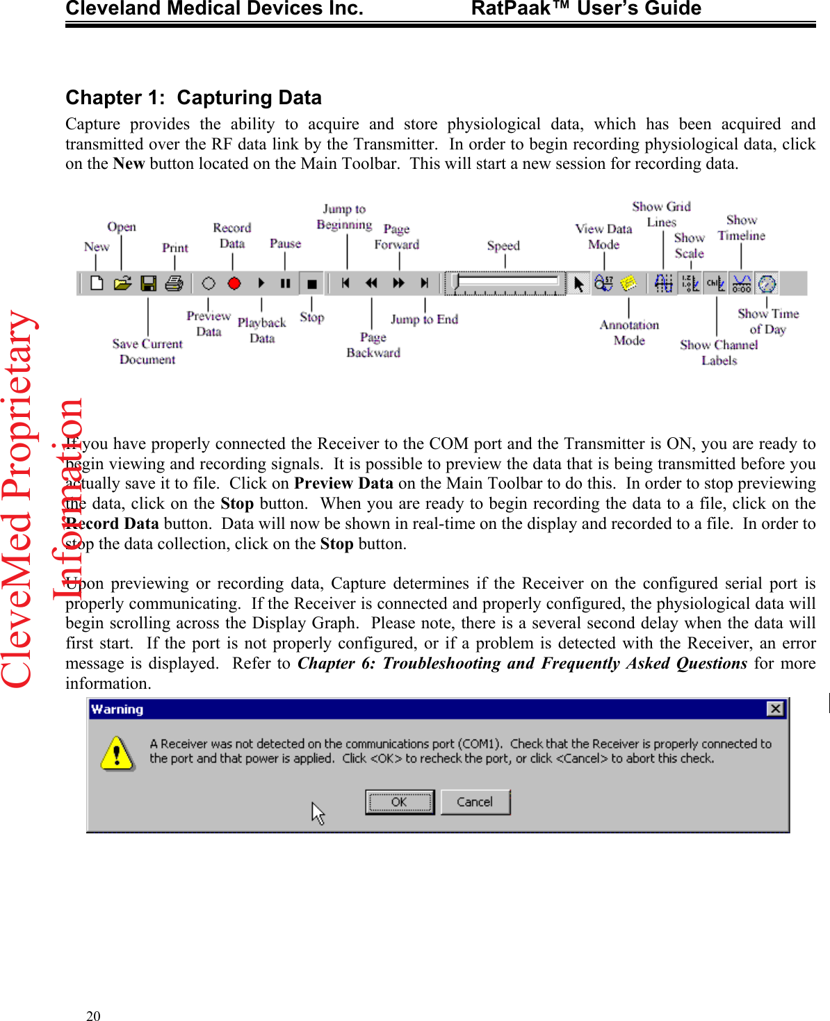
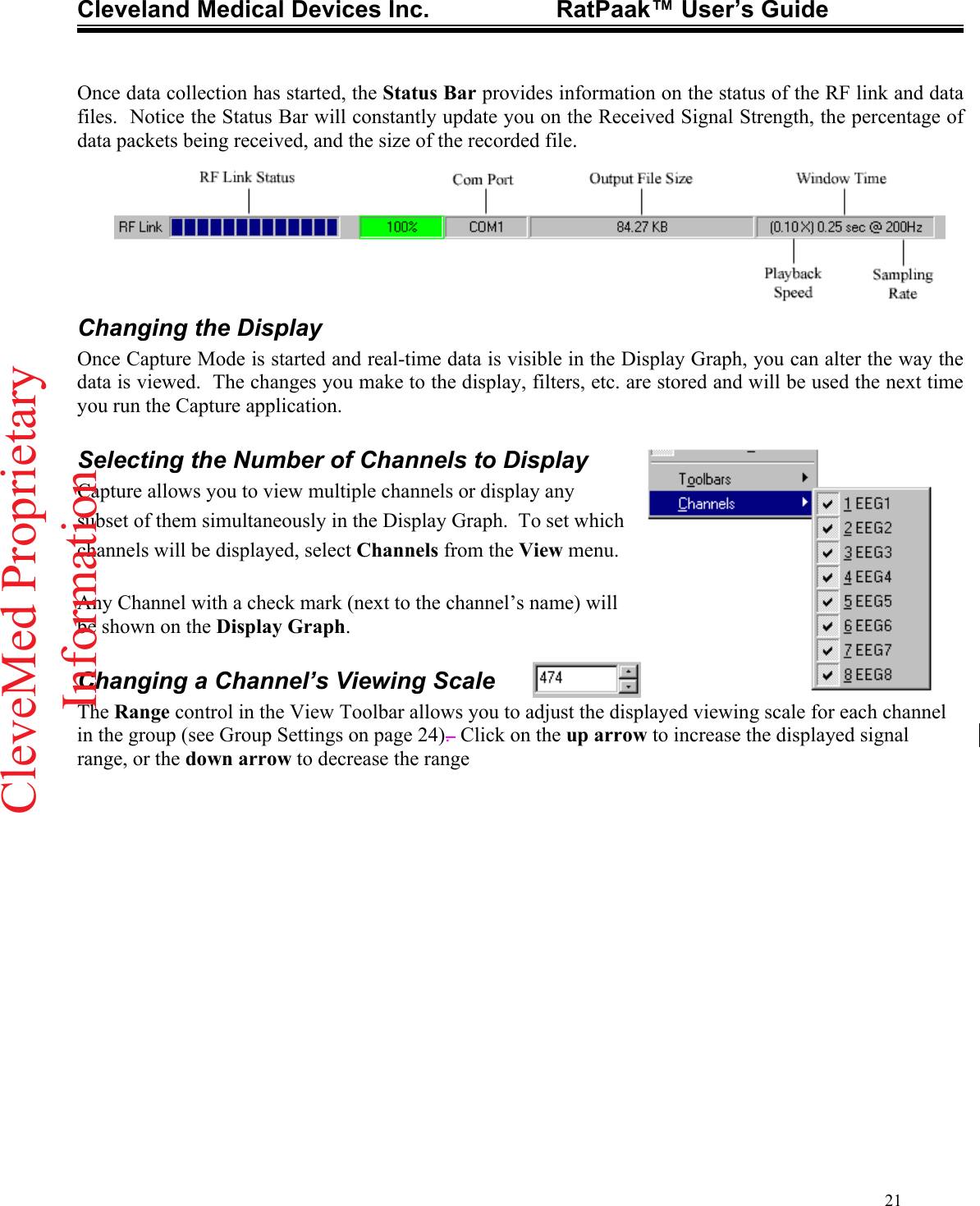
Cleveland Medical Devices
>
0051 User Manual
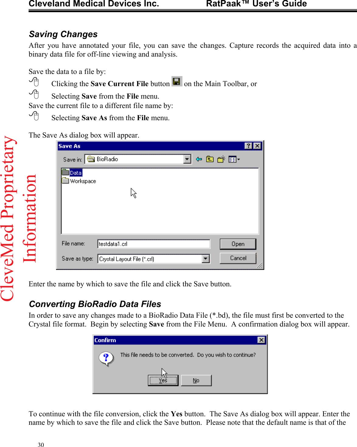
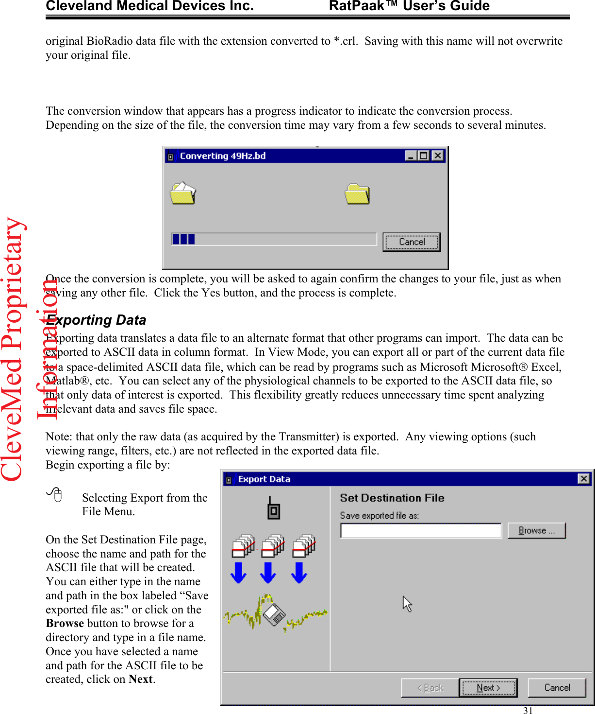
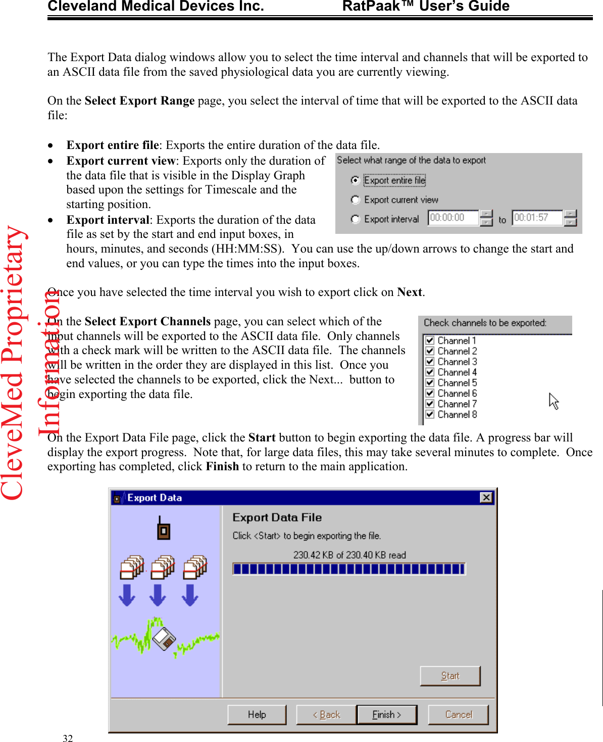
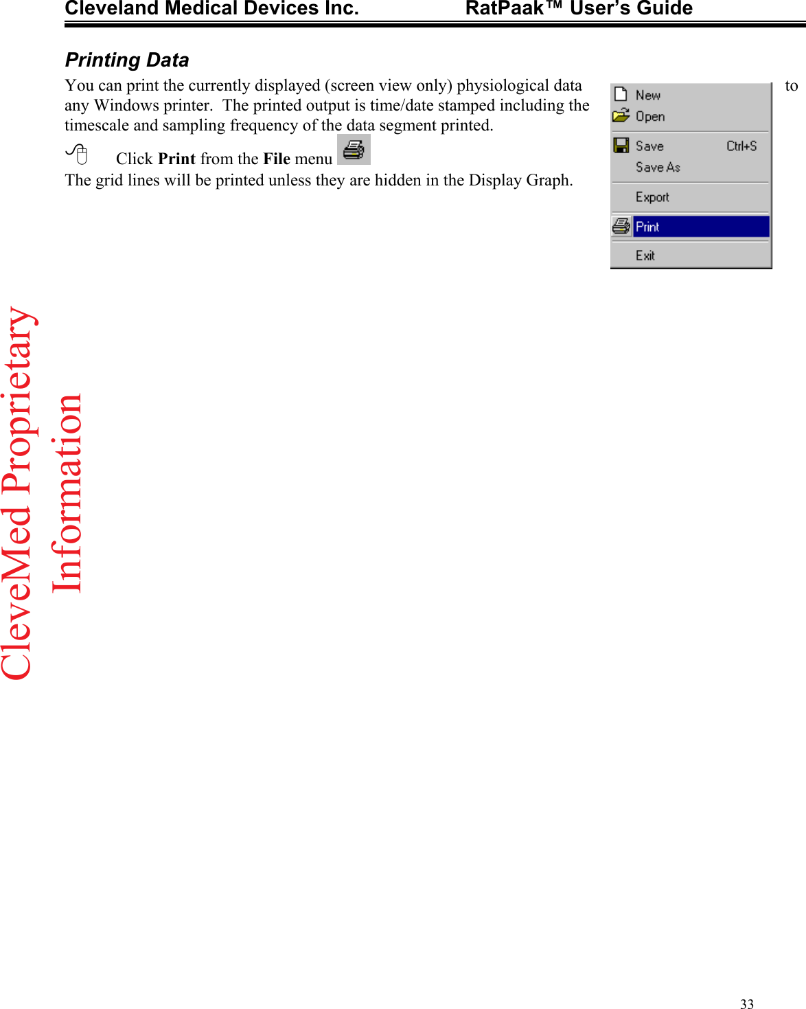
USERS MANUAL
Navigation menu
Upload a User Manual
Namespaces
Wiki Guide
HTML
PDF
Info
Views
User Manual
Discussion / Help
Navigation