Cleveland Medical Devices 0051 Low noise 2-ch wireless data acquistion system User Manual RatPaak
Cleveland Medical Devices Inc. Low noise 2-ch wireless data acquistion system RatPaak
USERS MANUAL
CleveMed Proprietary
Information

RatPaak™ Users Guide
Part Number: TBD
Telephone: (216) 791-6720 or Toll-free 1-877-CLEVEMED
9:00 a.m. - 5:00 p.m. EST
Monday - Friday
Fax: (216) 791-6739
E-Mail: support@clevemed.com
Web: http://www.clevemed.com
Mailing Address: Cleveland Medical Devices Inc.
4415 Euclid Ave
Cleveland, OH 44103
© Cleveland Medical Devices, Inc. 1999-2004
2
CleveMed Proprietary
Information

Chapter 1: Introduction.................................................................................................................................... 6
About RatPaak........... .................................................................................................................................. 6
Package Contents and Warranty Information.............................................................................................. 7
Minimum System Requirements ................................................................................................................. 7
Chapter 2: Installing Software & Setting-up Hardware .................................................................................. 8
Installing BioRadio™ Jr.Capture Software ................................................................................................. 8
Connecting the Receiver.......................................................................................................................... 8
Connecting the Receiver.......................................................................................................................... 9
Power Mains Interruptions .......................................................................................................................... 9
Transmitter Characteristics.......................................................................................................................... 9
Inserting or Replacing the Batteries .......................................................................................................... 10
Harness .................................................................................................................................................. 10
Wires.......................................................................................................................................................... 10
Chapter 3: Introduction to the Capture Software........................................................................................... 11
Starting the BioRadio Capture Program ................................................................................................... 11
Main Window ............................................................................................................................................ 12
Menu Bar ................................................................................................................................................... 13
Display Graph............................................................................................................................................ 13
Toolbars ..................................................................................................................................................... 14
Main Toolbar ......................................................................................................................................... 14
Status Bar............................................................................................................................................... 16
Setting Capture Options............................................................................................................................. 16
Transmitter Configuration: .................................................................................................................... 17
Setting the Receiver Port: ...................................................................................................................... 17
Annotation Presets:................................................................................................................................ 18
Testing the Equipment with the Test Pack ................................................................................................ 20
Chapter 1: Capturing Data ............................................................................................................................. 21
Changing the Display ................................................................................................................................ 22
Selecting the Number of Channels to Display....................................................................................... 22
Changing a Channel’s Viewing Scale ................................................................................................... 22
Channel Properties................................................................................................................................. 23
Changing the Timescale ........................................................................................................................ 24
Adding Filters to a Channel................................................................................................................... 25
Saving Collected Data ........................................................................................................................... 26
Chapter 2: Reviewing Data............................................................................................................................ 27
Viewing Saved Files.................................................................................................................................. 27
File Formats........................................................................................................................................... 27
BioRadio Data Files............................................................................................................................... 28
Changing the Display ................................................................................................................................ 28
Searching through Data ............................................................................................................................. 28
View Data Mode.................................................................................................................................... 29
Annotation Mode ................................................................................................................................... 29
Saving Changes ......................................................................................................................................... 31
Converting BioRadio Data Files............................................................................................................ 31
Exporting Data........................................................................................................................................... 32
Printing Data.............................................................................................................................................. 34
Chapter 3: Capture Command Reference...................................................................................................... 35
3
CleveMed Proprietary
Information

Cleveland Medical Devices Inc. RatPaak™ User’s Guide
File Menu................................................................................................................................................... 35
Open Data File…................................................................................................................................... 35
Save Data to file..................................................................................................................................... 35
Export Data File..................................................................................................................................... 35
Print........................................................................................................................................................ 35
Exit Capture ........................................................................................................................................... 35
View Menu ................................................................................................................................................ 36
Showing/Hiding the Grid....................................................................................................................... 36
Showing/Hiding the Scale ..................................................................................................................... 36
Showing/Hiding the Channel Labels ..................................................................................................... 36
Showing/Hiding the Timeline................................................................................................................ 36
Switching Between Elapsed Time and Time of Day............................................................................. 36
Showing/Hiding the Annotations .......................................................................................................... 36
Showing/Hiding the Annotation Lines .................................................................................................. 36
Showing/Hiding the Toolbars................................................................................................................ 37
Showing/Hiding the Channels ............................................................................................................... 37
Tools Menu................................................................................................................................................ 37
View Data Mode.................................................................................................................................... 37
Annotation Mode ................................................................................................................................... 37
Capture Options ..................................................................................................................................... 37
Record and Playback of Data .................................................................................................................... 39
Preview Live Data ................................................................................................................................. 39
Record Live Data................................................................................................................................... 39
Navigation Controls............................................................................................................................... 39
Playback Saved Data ............................................................................................................................. 39
Glossary ......................................................................................................................................................... 40
Trademark Acknowledgments....................................................................................................................... 41
Index .............................................................................................................................................................. 42
4
CleveMed Proprietary
Information

Cleveland Medical Devices Inc. RatPaak™ User’s Guide
Chapter 1: Introduction
About RatPaak™
The RatPaak™incorporates state-of-the-art wireless technology for viewing and recording physiological
signals such as electroencephalogram (EEG), electromyogram (EMG), electrocardiogram (ECG), or
electroculogram (EOG), in small laboratory animals, weighing 100 grams or more.
This two-channel general purpose signal monitor is the most unobtrusive, flexible, and convenient way of
measuring and transmitting physiological signals. Subjects can now be untethered. This allows behaviors
such as feeding, nesting, sleeping, and sexual activity to be observed without having the animal wired to a
cage. The remote monitoring and real-time data viewing capabilities of the RatPaak™ offer new
opportunities for researchers and scientists in the wireless monitoring of lab animals.
The RatPaak™ wireless physiological signal monitor consists of a Transmitter, a Receiver Assembly (the
receiver, receiver cable, and power supply), accessories (mounting band, screwdriver, batteries, and
harness), and a PC Operator Interface Software program. The integrated transmitter is compact enough that
it can fit comfortably on rats and other small animals without impeding their activities. The RatPaak™
transmitter weighs about one-quarter of an ounce and can transmit signals to a nearby receiver up to a
distance of 50 feet.
The RatPaak™ collects signals from wires attached to the subject, performs analog-to-digital conversion,
encoding, formatting, and transmitting of all signals. The signals are communicated using a 902-928 MHz
radio transmitter. Over one hundred transmitters can be used in the same area without interference with
one another. The Receiver Assembly receives the transmitted data packets, performs extensive error
detection and correction, and then sends the data through a Receiver cable to the PC Operator interface
where data can be stored, monitored in real time, or analyzed at a later time.
The RatPaak™ Capture program consists of several software components which allow the user to acquire,
store, view, and export physiological data as acquired by the RatPaak™ Transmitter. The software
provides a simple graphical interface for setting up and controlling data acquisition. In addition, several
functions are available to allow data acquired from the RatPaak™ Transmitter to be used in other software
applications, such as Matlab®, LabView™, and Excel. Programmability at the time of manufacture allows
various applications to be integrated into one system, allowing Cleveland Medical Devices to customize the
number of input channels, sampling rates, filters, gains and RF frequencies according to your research
needs.(is this correct?) As a flexible research tool by design, the RatPaak™ offers a new, low cost
monitoring solution for unrestrained animals, simplifying traditional monitoring applications.
This device is not FDA approved to market and is available for non-medical use only unless it is to be
used in an IRB approved program
5
CleveMed Proprietary
Information

Cleveland Medical Devices Inc. RatPaak™ User’s Guide
Package Contents and Warranty Information
Cleveland Medical Devices Inc. thanks you for your recent product purchase. For your benefit, we
recommend that you record the pertinent details below. If necessary, this information will allow us to
better serve your needs. We highly recommend that you staple a copy of the sales receipt to the blank
pages in the back of this manual.
Please check to make sure your kit has the required components and record the requested data:
S/N: __________________ Transmitter
S/N: __________________ Receiver
Receiver data cable (3 feet)
Serial cable for extension (9 pin - 9 pin, 6 feet)
9-volt battery adapter wire plug
AC Power adapter for Receiver
Three #675 batteries
Adjustable Velcro Mounting Band (36”)
Screwdriver
Harness
Ver: __________________ BioRadio Capture Installation Software (1 CD)
User’s Guide, this document
Warranty Form
Date of Purchase: ____________
Minimum System Requirements
• Personal computer with Pentium™/MMX™ 200 MHz or higher processor (or equivalent);
• Microsoft® Windows 95, Microsoft Windows 98, or Microsoft Windows NT Workstation version
3.51 or higher;
• 16 MB of installed memory for use on Windows 95 or Windows 98, 32 MB for use on Windows
NT;
• Minimum 50 MB free hard disk space (100 MB recommended);
• One 3.5” high-density floppy disk drive;
• VGA or higher resolution video adapter (SVGA 256-color recommended);
• Mouse or other pointing device;
• One free RS-232 serial port
6
CleveMed Proprietary
Information
Cleveland Medical Devices Inc. RatPaak™ User’s Guide
Chapter 2: Installing Software & Setting-up Hardware
Installing RatPaak™Capture Software
Close all Windows programs.
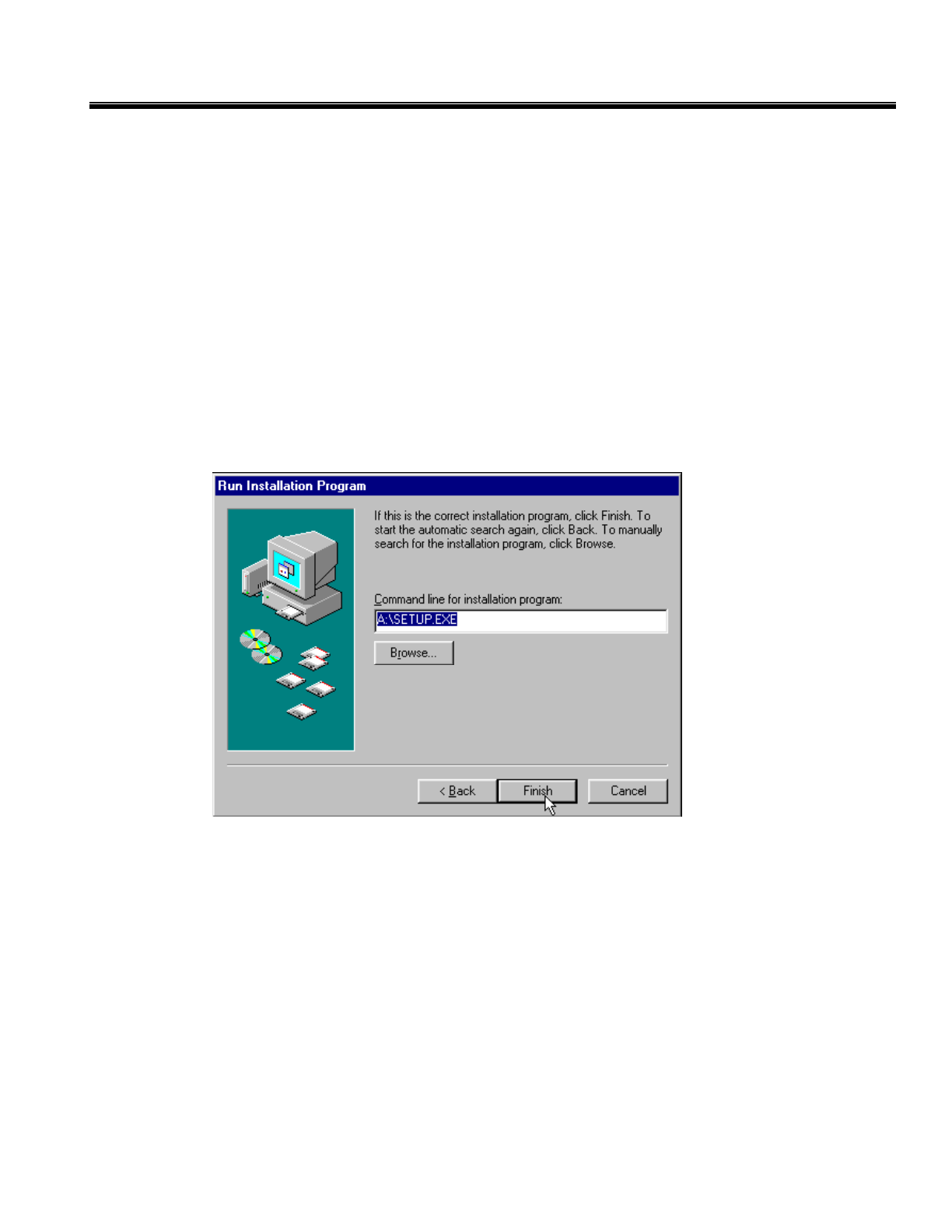
1. Place the CD in your cd-rom drive (usually D:).
2. Click the Start Button and choose Run and click on the Browse Button.
3. Select My Computer and choose the cd-rom drive (usually D:).
4. Select Setup.exe and follow the instructions for the installation of the software.
5. Click the Start Button and choose Run and click on the Browse Button.
6. Select My Computer and choose the cd-rom drive (usually D:).
7. Select Error! No property name supplied..exe and follow the instructions for the installation of the
software.
7
CleveMed Proprietary
Information
Cleveland Medical Devices Inc. RatPaak™ User’s Guide
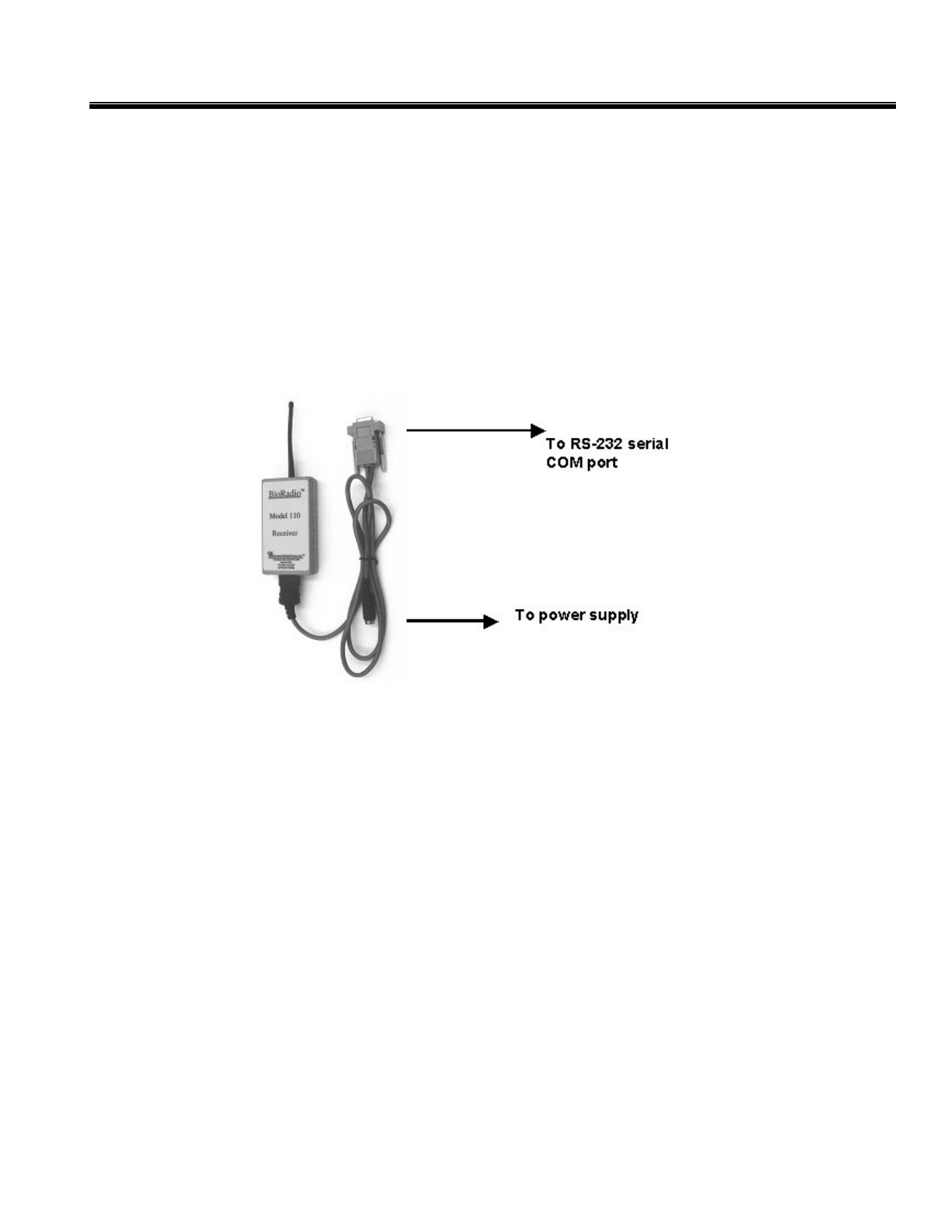
Connecting the Receiver
1. Connect the Receiver to a laptop or desktop computer using the Receiver data cable. The small end of
the 3-foot cable fits into the jack on the bottom of the Receiver. You will hear two clicks when the
connector is properly attached. The 9-pin end fits into your computer’s available RS-232 serial port.
Use the 6-foot DB-9 extension to add length to the 3-foot cable.
Note which port is used; (COM1, COM2, etc.) for configuration of the software. Refer to your PC’s
manual for information on setting up COM ports.
If the only available port is a 25-pin port, you will need to use a 25-9 pin adaptor (not provided but
available at most electronic stores).
2. Power the Receiver by plugging in the AC adapter power cord (primary power source, typically used
for desktop applications), or attaching a 9-volt battery via the 9-volt battery adapter wire plug
(typically used for mobile laptop applications)
Power Mains Interruptions
If the user of the RatPaak™ requires continued operation during power mains interruptions, it is
recommended that the RatPaak™ Receiver be used in conjunction with a laptop instead of a desktop
computer. A laptop can continue processing the data for extended periods of time through power main
interruptions or in stand-alone remote situations. (Refer to the laptop’s manual for more specific details
on the length of duration of its batteries.) For reliable data collection in a laboratory setting, the
RatPaak™ Receiver and personal computer can be powered from an uninterruptible power supply
(UPS). The usage of a UPS will only enable continued monitoring of patient signals during power
mains interruptions and not extended power loss. If there is a power loss the UPS will signal the
operator and a controlled suspension of patient monitoring and the closing of recorded data can be
performed.
Transmitter Characteristics
8
CleveMed Proprietary
Information
Cleveland Medical Devices Inc. RatPaak™ User’s Guide
The RatPaak™ system consists of a transmitter and receiver operating in the ISM frequency band (902 to
928 MHz). This device has been type certified by the FCC and therefore the user does not need a license.
There are 256 possible frequency settings or channels selected by the manufacturer. The RatPaak™ default
is channel 148 or a frequency of 916.5312 MHz. The Receiver has a 110 kHz bandwidth.
Warning: Other equipment may interfere with the RatPaak™, even if that other equipment complies
with emission requirements.
Inserting or Replacing the Batteries
The batteries need to be put in the first time you use your RatPaak™ Insert each #675 battery into one of
the three battery compartments of the battery holder; making sure that the positive (+) side is facing
upwards.
Warning: It is important that the batteries are installed with the proper polarity.
Warning: The isolation and safety of the patient is assured by battery operation. The powering of the
Transmitter by any other means is NOT RECOMMENDED.
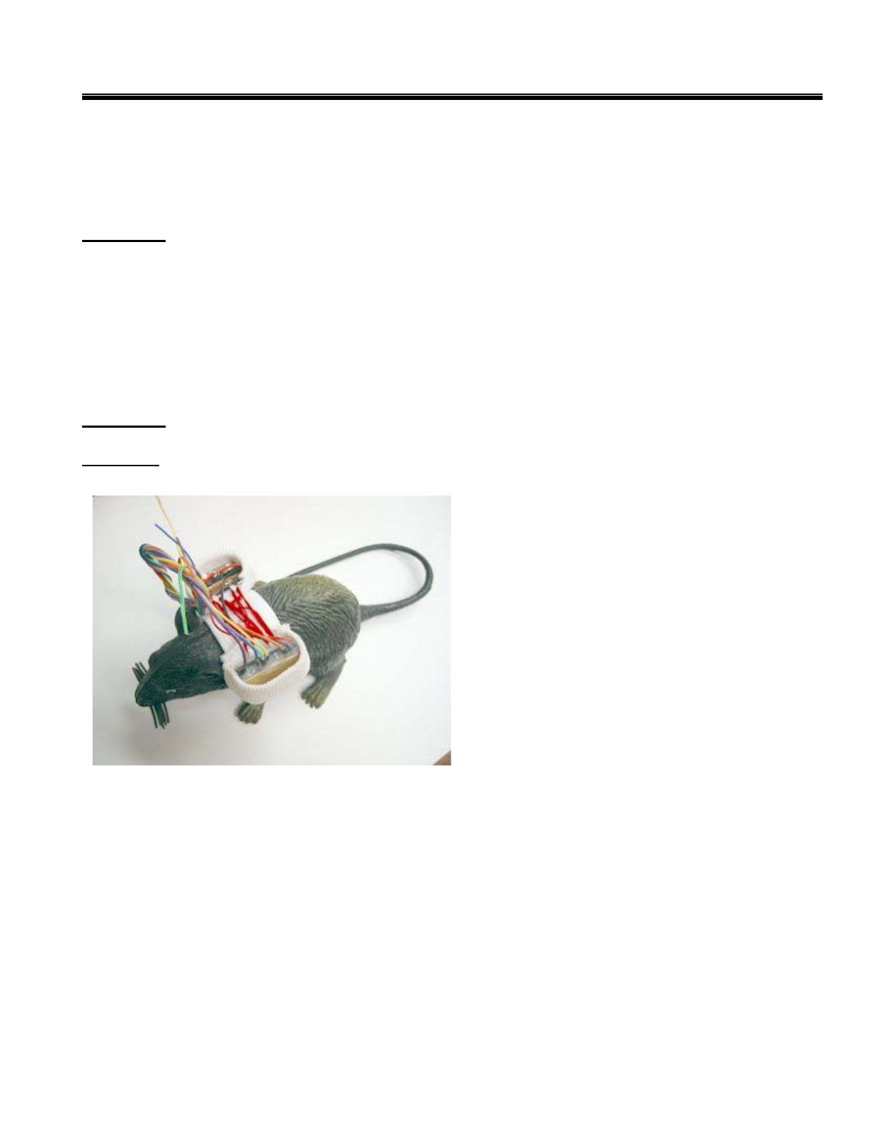
Harness
A harness is provided with the RatPaak™ as a
means to secure the RatPaak™ and batteries to the
subject. The harness has two fitted pockets. The
batteries should be stored in one pouch of the vest
and the battery holder in the other pouch.
Wires
The RatPaak™ has multi-colored wires
protruding from the transmitter. Two of these
wires, the black and red wires, are attached to
both of the RatPaak™ and the battery. These
wires should be routed over the subject’s back as
the devices are being placed in the pockets of the
harness. The blue wire serves as the antenna, which will transfer the signal from the RatPaak™ to the
Receiver. It should be tucked under the harness in a manner that will prevent damage to the wire from the
subject. It is important that the blue wire be kept straight so that it can transfer the signal. The remaining
wires should be connected to the subject to produce the two output Channels. Each Channel has two
inputs, a positive input and a negative input. In Channel 1, orange is the positive input and orange with a
white tracer is the negative input. In Channel 2, violet is the positive input and violet with a white tracer is
the negative input. Brown should be connected to a ground..
9
CleveMed Proprietary
Information

Cleveland Medical Devices Inc. RatPaak™ User’s Guide
Chapter 3: Introduction to the Capture Software
The RatPaak Wireless Physiological Monitor consists of several software components that allow the user
to acquire, store, view, and translate the analog signal data acquired by the RatPaak Transmitter. The
software provides a simple graphical interface for setting up and controlling data acquisition. In addition,
several functions are available to allow data acquired from the RatPaak Transmitter to be used in other
software applications, such as Matlab®, Microsoft Excel, etc.
This chapter serves as a brief tutorial designed to help you quickly begin using your RatPaak. It covers
the basic tasks of capturing test signals, changing the display screen, recording the signals, and configuring
the RatPaak. The RatPaak Capture Program is factory set for an EEG configuration. Thus the
Transmitter and Receiver are programmed to use the RatPaak EEG configuration and will need to be
reprogrammed using the RatPaak Configuration Wizard for other applications. For more detailed help on
Commands refer to Chapter 5: RatPaak Command Reference.
Starting the RatPaak Capture Program
1. Click on the Start Menu
2. Point to Programs
3. Point to RatPaak folder
4. Click on RatPaak Capture
10
CleveMed Proprietary
Information
Cleveland Medical Devices Inc. RatPaak™ User’s Guide
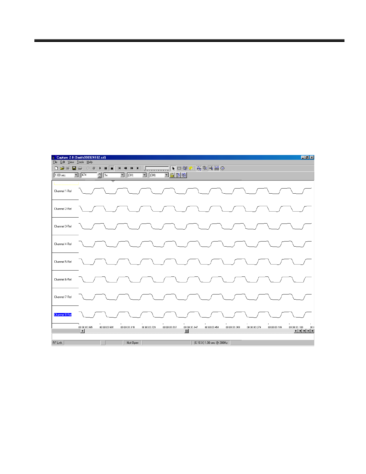
Main Window
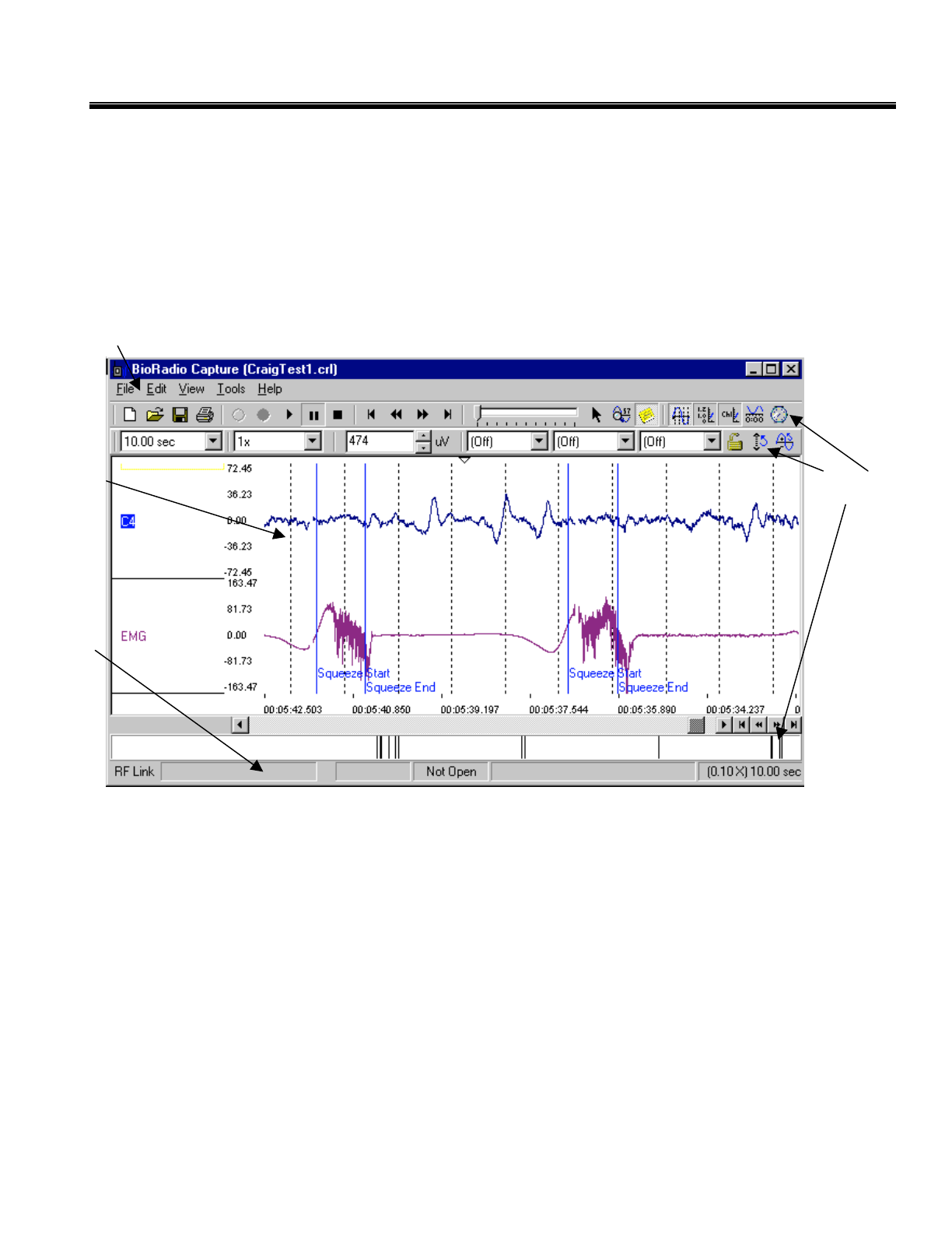
The Capture program displays physiological signals as measured by the Transmitter in a real-time scrolling
graph. Multiple channels can be viewed simultaneously. The graphical display can be customized: each
analog channel can be scaled (Y-axis) and the Timescale (X-axis) can be zoomed. The display color of
each channel can be customized. Commands can be accessed either using the drop down menus located on
the Menu Bar or by clicking on the command buttons on the Toolbar.
Status
Bar
Menu Bar
Toolbars
Display
G
ra
p
h
11
CleveMed Proprietary
Information
Cleveland Medical Devices Inc. RatPaak™ User’s Guide
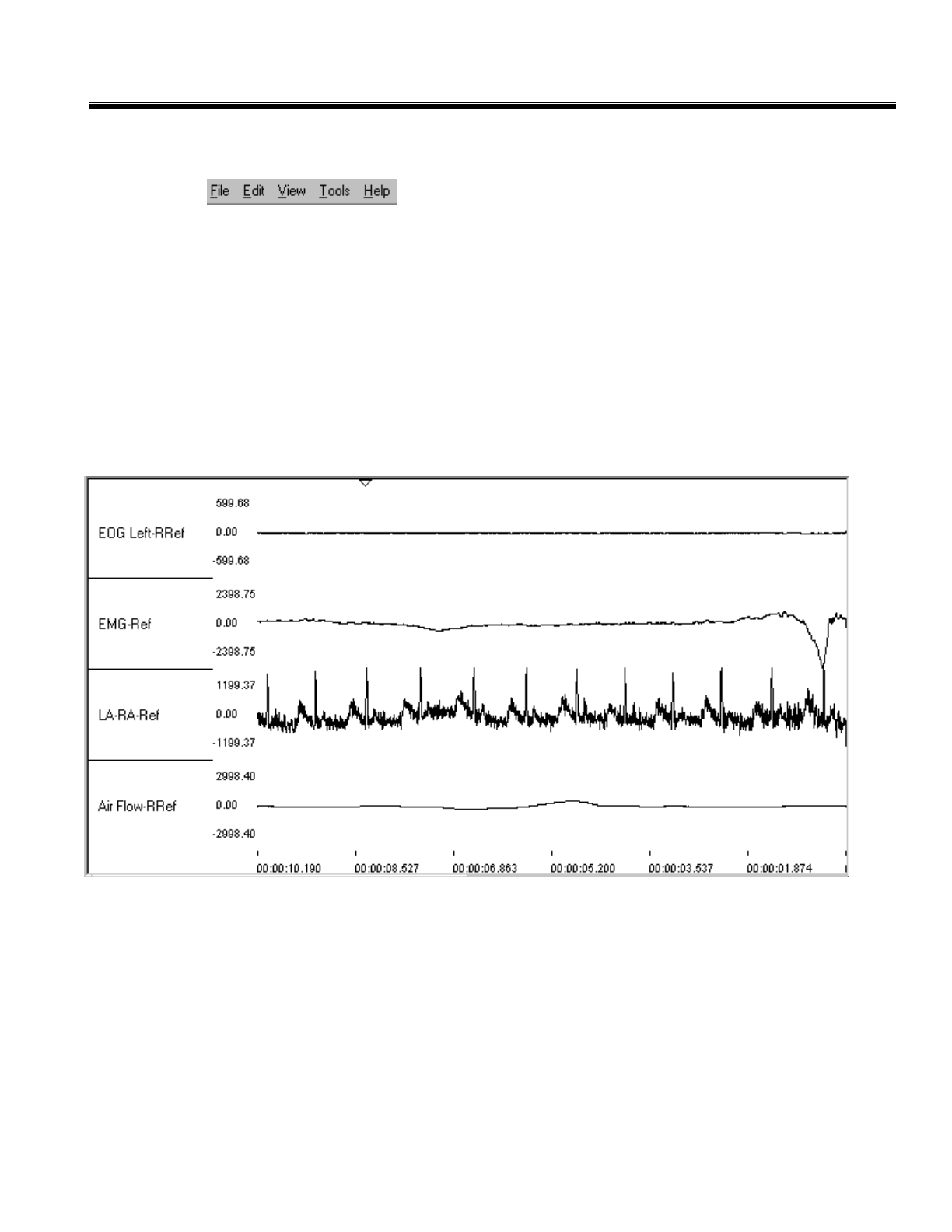
Menu Bar
The Menu Bar contains the File, Edit, View, Tools, and Help menus. The File
drop-down menu has commands that allow you to open and save a file, as well as accessing other options.
The Edit menu contains commands for prompt revisions to a file. The View menu contains all of the
screen configuration commands. The Tools menu contains a set of commands to alter the viewing mode.
The Help menu contains software versioninformation.The Help menu contains a search index of all the
commands and how to use them in addition to version information.
Display Graph
The Display Graph shows up to eight channels of data. You can customize which channels are viewed by
selecting them from the Channels section under the View Menu.
12
CleveMed Proprietary
Information
Cleveland Medical Devices Inc. RatPaak™ User’s Guide
Toolbars
The toolbars are sets of buttons and other tools, such as drop-down boxes and sliders, that provide
command shortcuts for working with Capture. Using a toolbar button is usually quicker than choosing a
command from a menu. There are two toolbars on the Capture screen, the main toolbar and the View
Toolbar. Pause your mouse pointer over a toolbar button to see a tooltip that defines the button’s function.
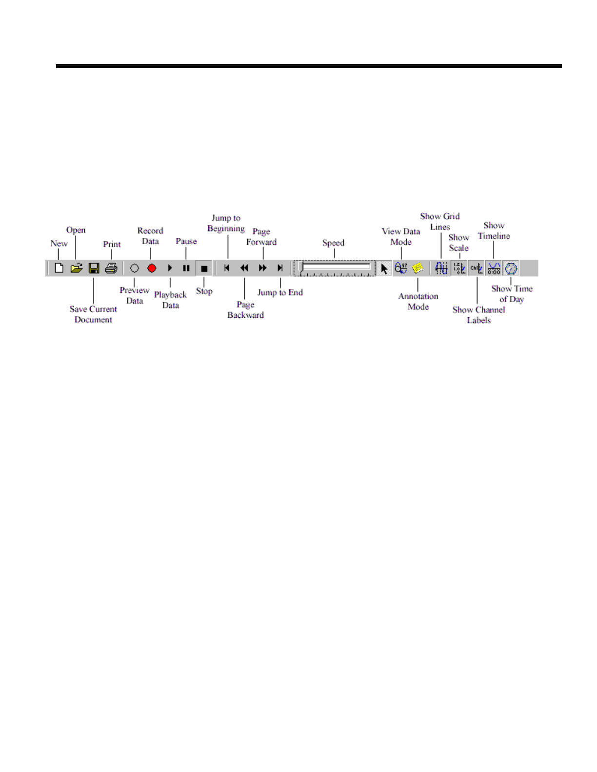
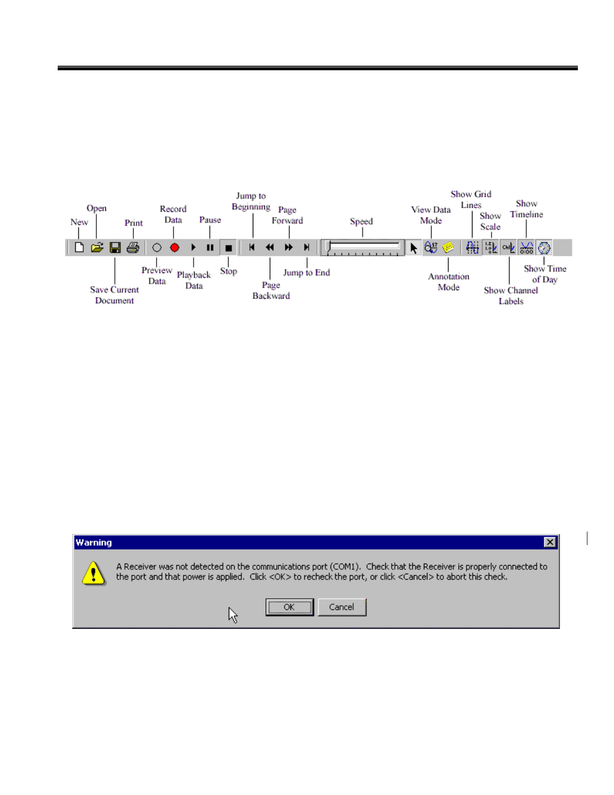
Main Toolbar
File Menu Shortcuts
The following toolbar buttons provide quick access to the most used functions available from the File
Menu:
New: starts a new capture session with the current transmitter configuration.
Open: displays the open dialog to view a data file.
Save: displays the save dialog in order to save the current data file.
Print: displays the print dialog in order to print the current screen.
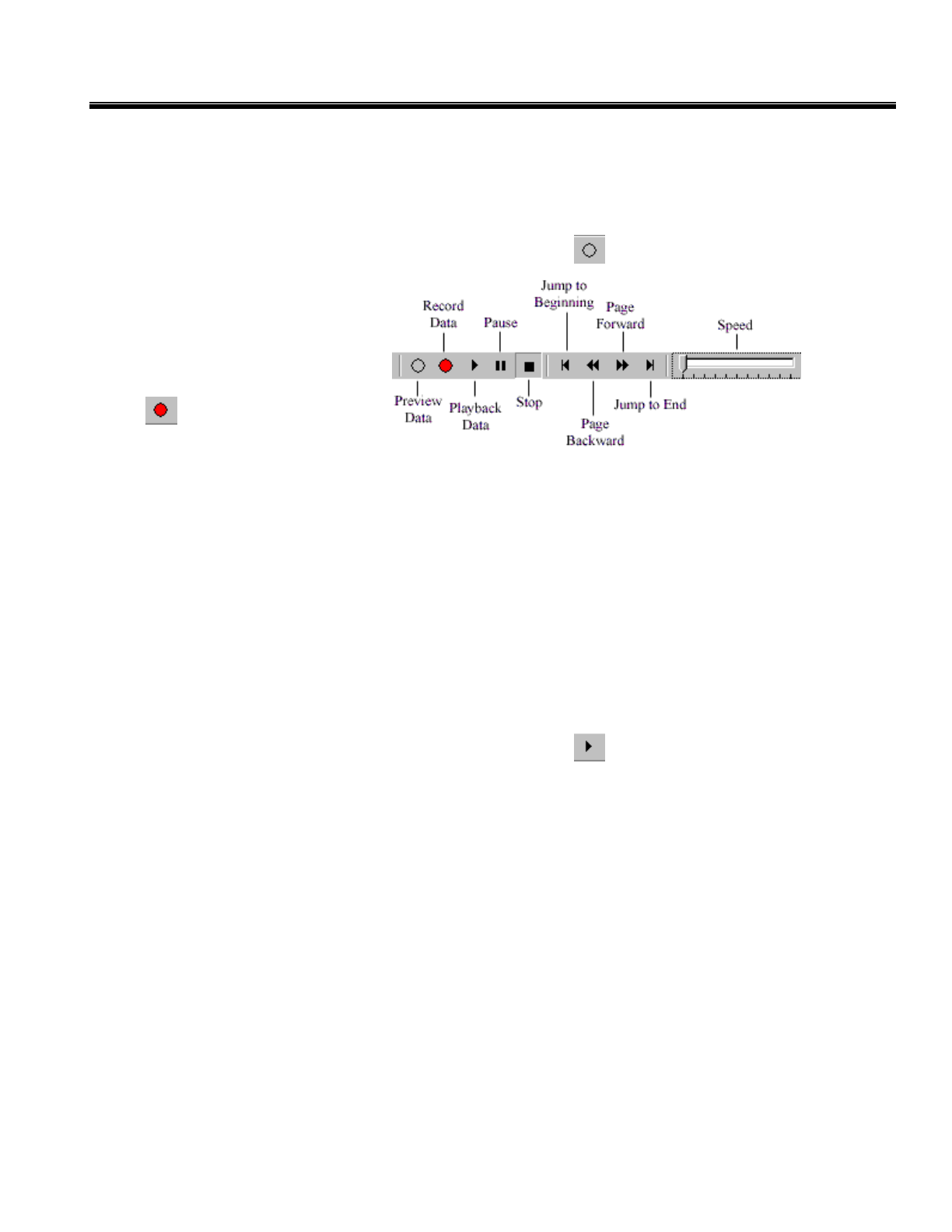
Operation Controls
The following toolbar buttons comprise the data recording and playback console:
Preview Data: allows the user to view live data without having to save it to disk.
Record Data: begins streaming of live data to disk.
Playback Data: begins playback of a data file.
Pause: pauses record and playback operations.
Stop: stops the current operation
Speed: controls the playback speed with a range of 1/10 to 100 times the sampling rate.
* See “Chapter 4: Opening and Playing Back Data Files” for more details
Navigation Controls
The following toolbar buttons provide convenient navigation functions to aid in reviewing data files:
Jump to Beginning: moves the display to the beginning of the data file.
Page Backward: moves to display back one page (page size dictated by the Timescale setting.)
13
CleveMed Proprietary
Information
Cleveland Medical Devices Inc. RatPaak™ User’s Guide
Page Forward: moves to display forward one page (page size dictated by the Timescale
setting.)
Jump to End: moves the display to the end of the data file.
* See “Chapter 4: Opening and Playing Back Data Files” for more details
Viewing Mode Shortcuts
The following toolbar buttons allow you to change viewing modes:
View Data Mode: puts the display into View Data Mode.
Annotation Mode: puts the display into Annotation Mode.
Display Setting Shortcuts
The following toolbar buttons allow you to customize several display settings:
Show Grid Lines: toggles the display of vertical grid lines, which appear for every one second
of data.
Show Scales: toggles the display of the scales for all channels.
Show Labels: toggles the display of the name labels for all channels.
Show Time line: toggles the display of the time line.
Show Time of Day: toggles the display of real time and time of day.
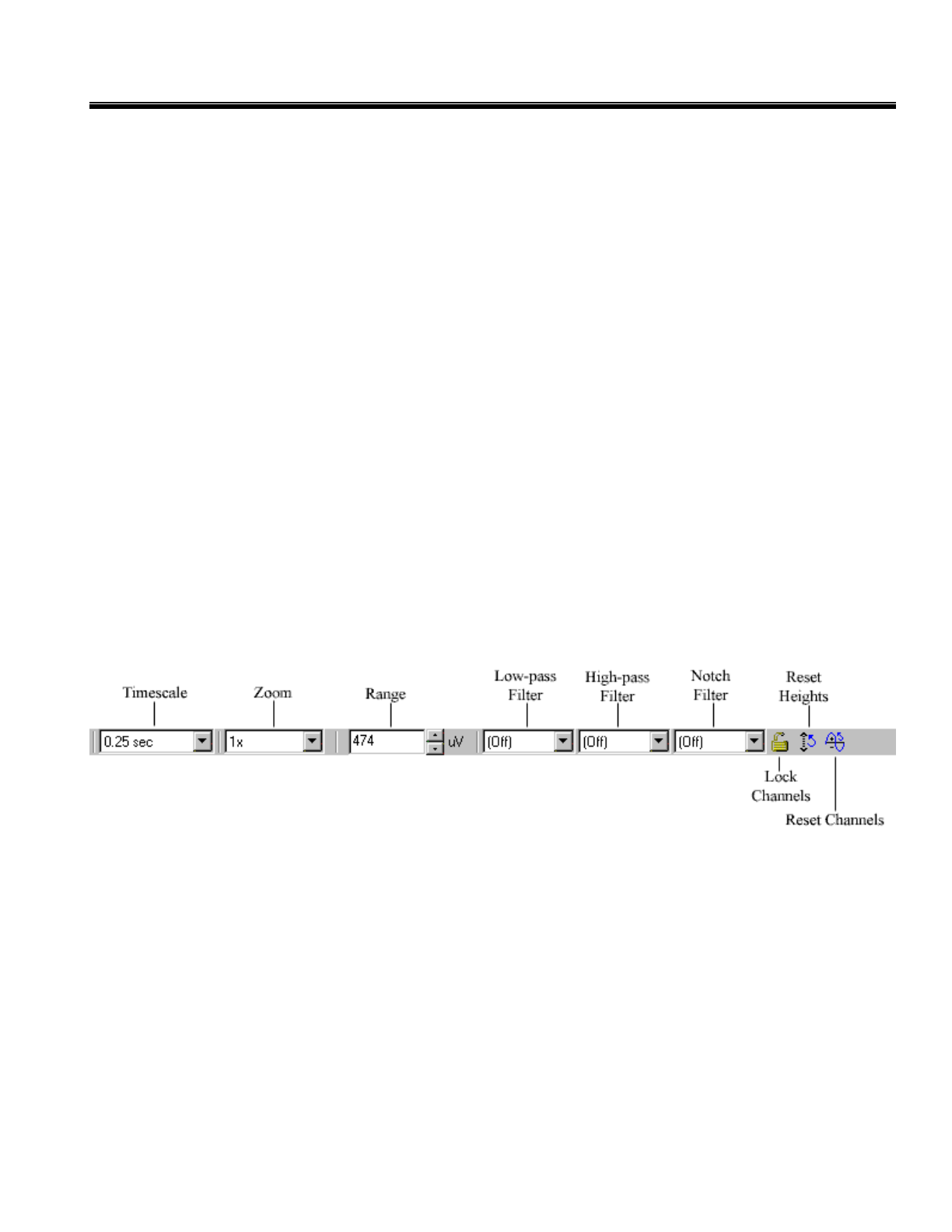
View Toolbar
The View Toolbar is a collection of controls that allow provide access to various settings that allow you to
control how you view your data.
The Timescale control is a drop down box of times that will be displayed on the screen ranging from 0.25
seconds to 60 seconds. The same Timescale will be displayed for each channel.
The Zoom control allows you to increase the size of the channel displays on the display graph without
changing the actual range of the voltages you are viewing. Zoom is a drop down menu that allows you to
increase the display to 1, 2, 3, or 4 times its original size.
The Range control allows you to adjust the displayed viewing scale for each channel in the group (see
Group Settings on page 24). Click on the up arrow to increase the displayed signal range, or the down
arrow to decrease the range.
*Note: changing the scale controls does not affect how the data is stored
14
CleveMed Proprietary
Information
Cleveland Medical Devices Inc. RatPaak™ User’s Guide
The Low and High Pass Filter settings for all channels using group settings can also be set on this tool
bar. The filters can be turned off, or the cutoffs can be selected from the values in the drop down menus.
The Notch Filter setting for all channels using group settings can be turned off, set to 50Hz, or set to
60Hz.
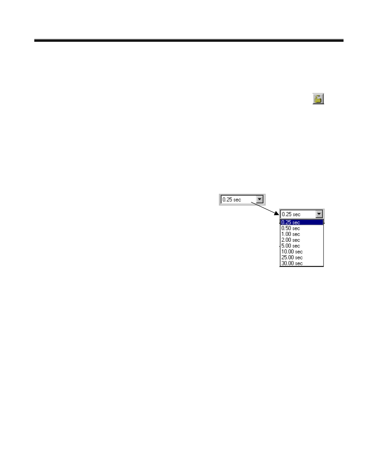
To modify the parameters for ALL channels at once, click on the Lock/Unlock Controls button on the
View Toolbar. The properties (including range, zoom, and filtering options) for all channels will now be
set using the controls on the View Toolbar.
Clicking on Reset Channels will reset ALL of the channel parameters to the default settings.
Clicking on Reset Heights will cause all channels to revert to the default height on the screen, which is
defined to give all channels an equal height.
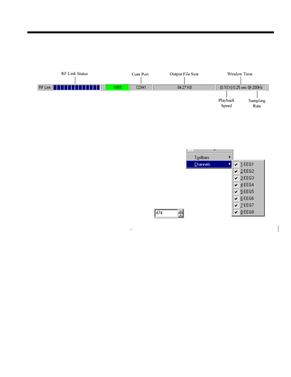
Status Bar
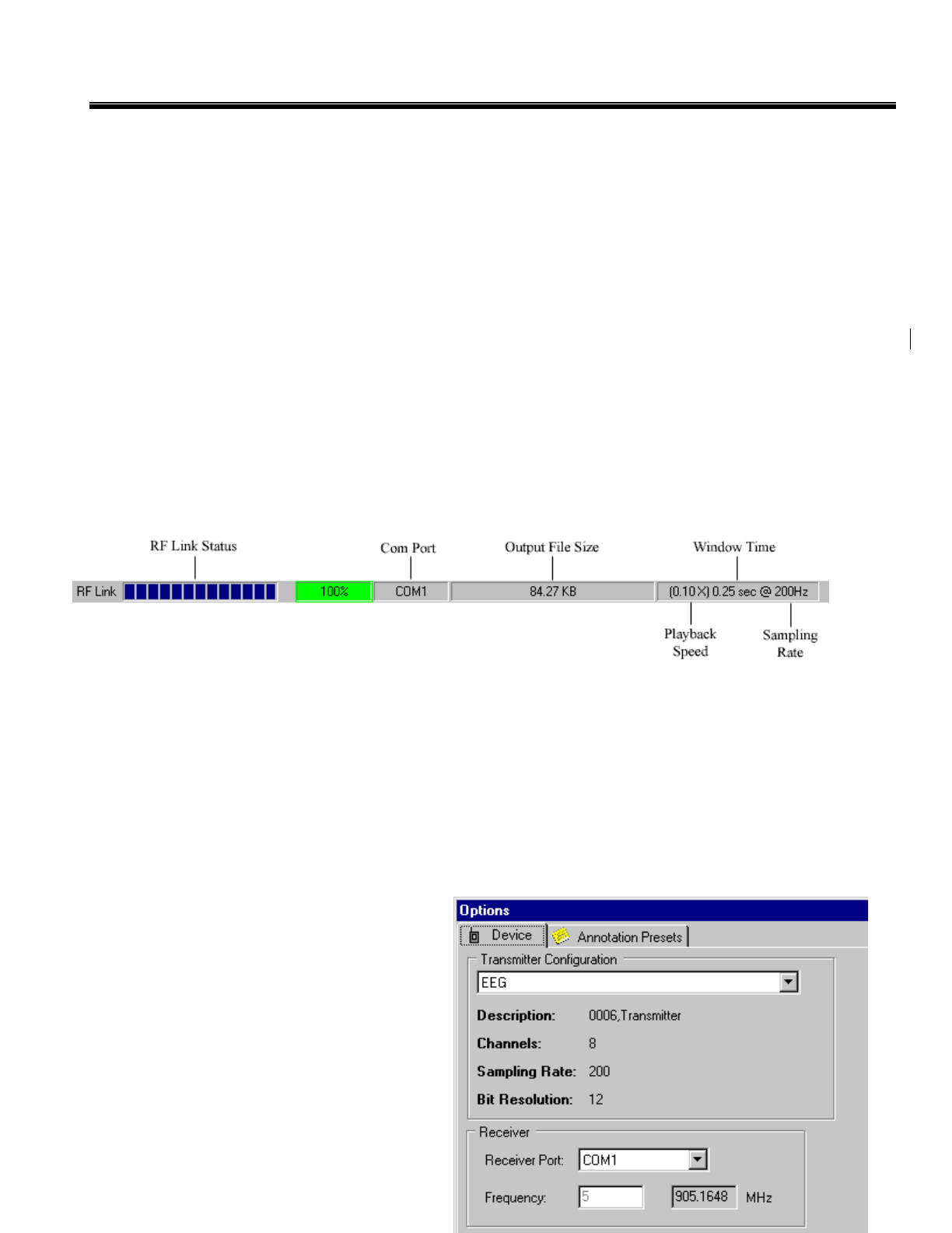
Located at the bottom of the screen, the Status Bar provides real-time status of the data acquisition and RF
link operation. This information includes:
• RF Link Status: The bar graph shows an approximate measure of the signal strength from the
Transmitter. The bar shrinks when the received signal is getting weaker and there is greater chance for
losing data. The percentage displays the current percent of received packets from the transmitter.
When the percent of received packets is 100%, the percentage displayed is highlighted in green. When
this number drops below 100%, the percentage displayed appears highlighted in yellow. If this number
drops below 50% it is highlighted in red. This occurs because RF transmission is being impeded.
When this happens, move the Transmitter closer to the Receiver or remove the number of obstacles
between the Transmitter and Receiver.
• COM Port: Displays the current serial port setting for communicating with the Receiver.
• Output File Size: Displays the size of the
current output file, when recording data to
a file.
• Playback Speed/Timescale/Sample
Rate: Displays the speed of playback for a
file, timescale (viewing width), and the
sample rate of the Transmitter.
Setting Capture Options
Before capturing data with Capture, you must
configure the hardware.
15
CleveMed Proprietary
Information

Cleveland Medical Devices Inc. RatPaak™ User’s Guide
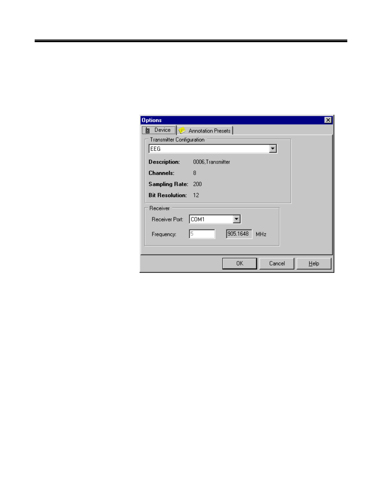
Access the Capture Options dialog by selecting Options from the Tools menu.
Transmitter Configuration:
The Device Options tab allows you to view the configuration to which the Transmitter was programmed.
You can specify the transmitter configuration from the options listed in the drop-down box.
Setting the Receiver Port:
Using the Receiver Port drop-down menu, choose the port to which your Receiver is attached (e.g. COM
1, 2, 3 or 4). (the port to which your Receiver is attached) If you are uncertain about the COM port setting,
refer to the documentation that came with your computer. The Device Options tab also allows you to view
the frequency to which the Receiver was programmed. Click OK when finished.
16
CleveMed Proprietary
Information
Cleveland Medical Devices Inc. RatPaak™ User’s Guide
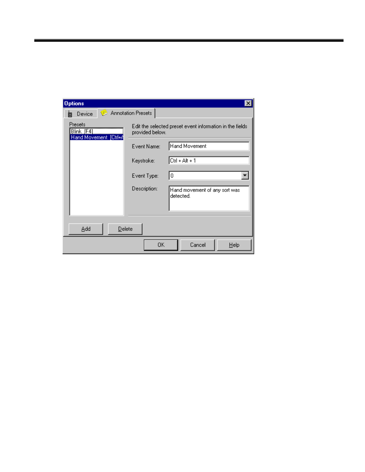
Annotation Presets:
Capture Options allows you to create predetermined bookmarks to identify specified points of interest in a
data file. These annotations can be added to a file while data is being collected in real-time, or they can be
added later to a saved data file. These annotations serve as an indicator when tracking occurrences of a
specified event.
To create a new annotation, first enter the name of the event. Next, type in the keystroke for the annotation
(this can be any of the F<#> keys or <CTRL> + <ALT> in combination with any letter or number).
Whenever this keystroke is entered, while data is being collected, a vertical line will appear in the recorded
waveform along with the name of the event. A description of the event can also be entered (a brief
statement of the purpose for each annotation might be helpful when the user is reviewing the list of
annotations). The annotations are stored under Presets for future manipulation.
Directly beneath the list of annotations is the Add and Delete Buttons. The Add button clears the fields
and allows the user to enter information for another annotation. The Delete button erases the annotation
that is highlighted in the list of Presets.
17
CleveMed Proprietary
Information
Cleveland Medical Devices Inc. RatPaak™ User’s Guide
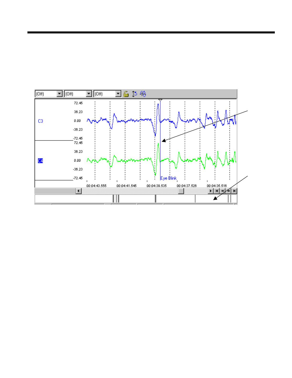
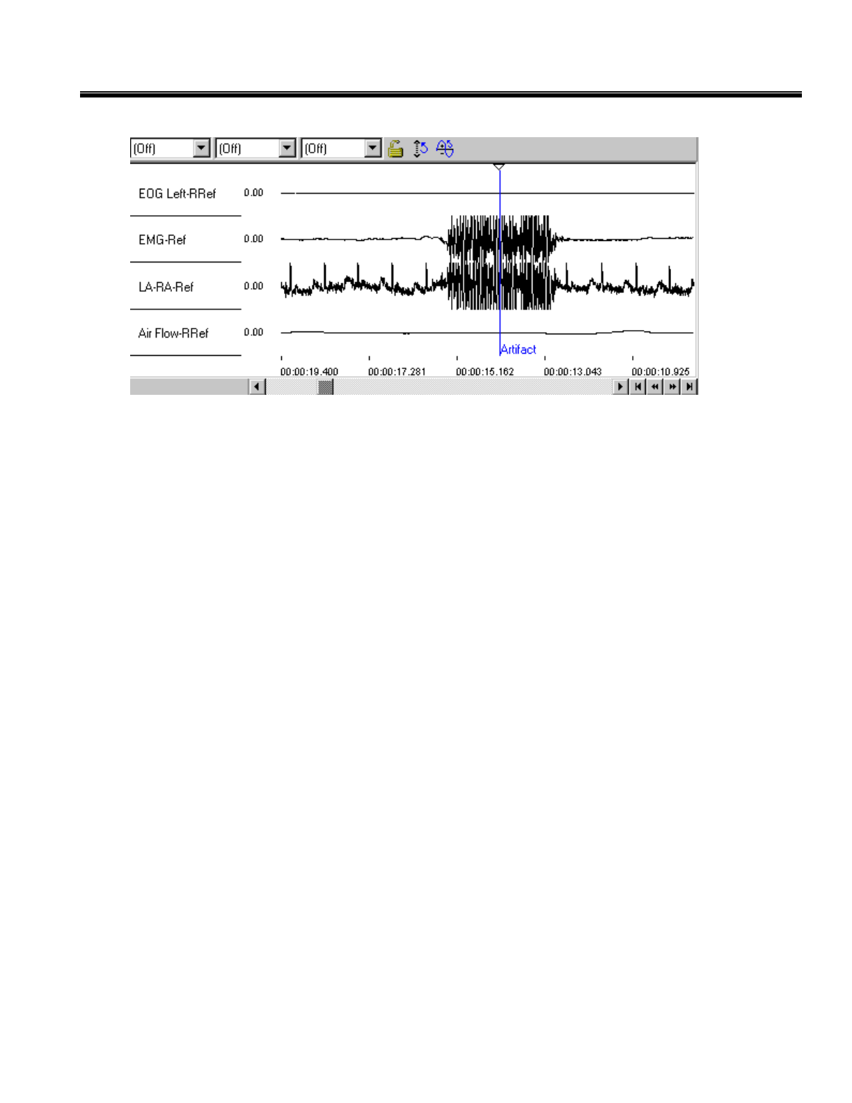
To annotate the waveform while the system is collecting data in real-time or while reviewing a file, enter
the annotation’s keystroke. The annotation will appear in the waveform wherever the upside down triangle
marker is located when the keystroke is pressed. This marker can be moved back and forth on the top of
the display graph by clicking on it and dragging it with the mouse. All annotation lines can be seen in the
annotation toolbar. Double-clicking on one of these annotation lines will move the display graph to that
point in time.
Annotation
Toolbar
Annotations
Marker
18
CleveMed Proprietary
Information
Cleveland Medical Devices Inc. RatPaak™ User’s Guide
Testing the Equipment with the Test Pack
1. Plug the Receiver into an available RS-232 computer port using the serial port cable and connect the
AC Adapter power cord (or 9V battery) to the serial port cable.
2. Check to see that the COM port is displayed on the Status Bar. It should correspond with the COM port
chosen in the Device tab of the Options screen.
3. Connect the Transmitter to the Test Pack.
4. Turn the Transmitter “ON” by flipping the ON/OFF switch. The Transmitter serves as the power
source to the Test Pack.
5. Click the Preview Data button on the Main Toolbar.
A 10 Hz, 300µV peak-to-peak square wave should scroll across the screen. If you do not receive a visible
signal, refer to Capturing Data or Chapter 6, Troubleshooting.
19
CleveMed Proprietary
Information
Cleveland Medical Devices Inc. RatPaak™ User’s Guide
Chapter 1: Capturing Data
Capture provides the ability to acquire and store physiological data, which has been acquired and
transmitted over the RF data link by the Transmitter. In order to begin recording physiological data, click
on the New button located on the Main Toolbar. This will start a new session for recording data.
If you have properly connected the Receiver to the COM port and the Transmitter is ON, you are ready to
begin viewing and recording signals. It is possible to preview the data that is being transmitted before you
actually save it to file. Click on Preview Data on the Main Toolbar to do this. In order to stop previewing
the data, click on the Stop button. When you are ready to begin recording the data to a file, click on the
Record Data button. Data will now be shown in real-time on the display and recorded to a file. In order to
stop the data collection, click on the Stop button.
Upon previewing or recording data, Capture determines if the Receiver on the configured serial port is
properly communicating. If the Receiver is connected and properly configured, the physiological data will
begin scrolling across the Display Graph. Please note, there is a several second delay when the data will
first start. If the port is not properly configured, or if a problem is detected with the Receiver, an error
message is displayed. Refer to Chapter 6: Troubleshooting and Frequently Asked Questions for more
information.
20
CleveMed Proprietary
Information
Cleveland Medical Devices Inc. RatPaak™ User’s Guide
Once data collection has started, the Status Bar provides information on the status of the RF link and data
files. Notice the Status Bar will constantly update you on the Received Signal Strength, the percentage of
data packets being received, and the size of the recorded file.
Changing the Display
Once Capture Mode is started and real-time data is visible in the Display Graph, you can alter the way the
data is viewed. The changes you make to the display, filters, etc. are stored and will be used the next time
you run the Capture application.
Selecting the Number of Channels to Display
Capture allows you to view multiple channels or display any
subset of them simultaneously in the Display Graph. To set which
channels will be displayed, select Channels from the View menu.
Any Channel with a check mark (next to the channel’s name) will
be shown on the Display Graph.
Changing a Channel’s Viewing Scale
The Range control in the View Toolbar allows you to adjust the displayed viewing scale for each channel
in the group (see Group Settings on page 24). Click on the up arrow to increase the displayed signal
range, or the down arrow to decrease the range
21
CleveMed Proprietary
Information
Cleveland Medical Devices Inc. RatPaak™ User’s Guide
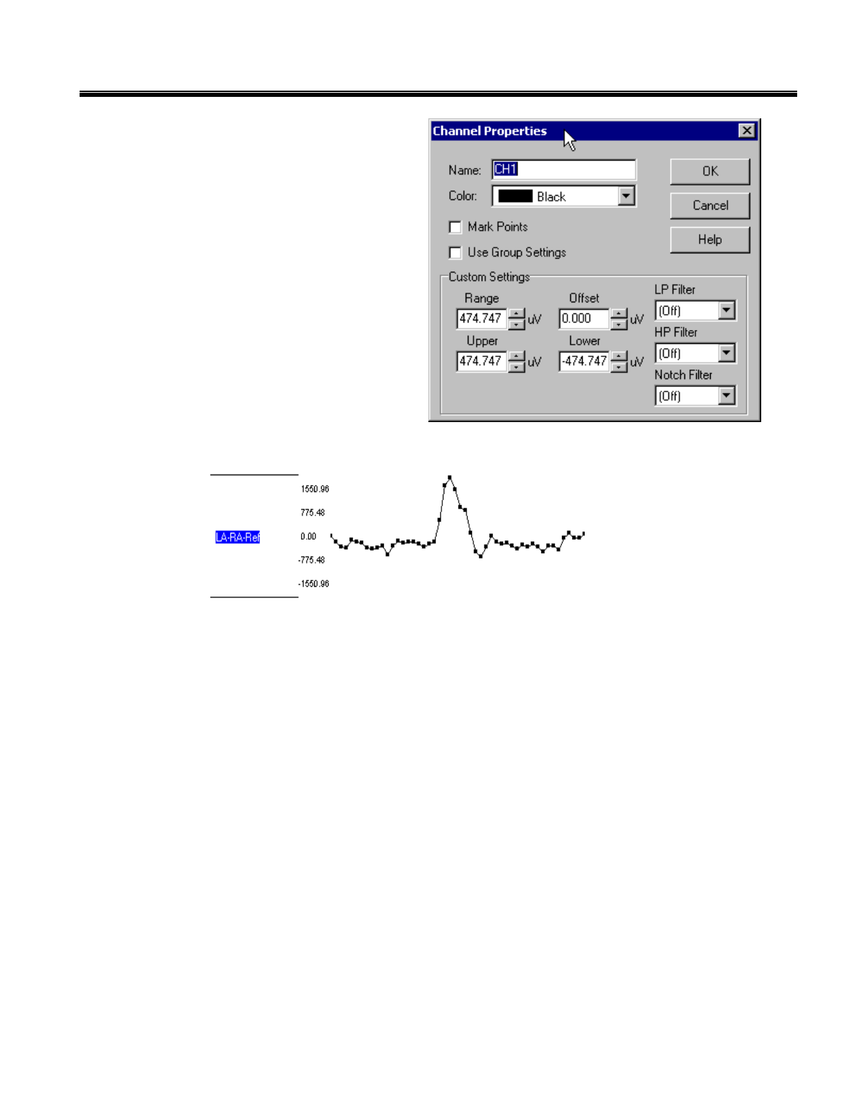
Channel Properties
The properties of each channel can be configured
on an individual basis. Channel properties can
be viewed by double clicking on any channel
name on the display graph. Later we will discuss
setting the properties for all channels at once by
locking or using group settings. The default
names for the channels are taken from the
configuration file that the unit was programmed
with. The channel name can be changed by
entering the desired name in the field labeled
“Name”. Additionally, clicking on the Color
drop-down box and choosing a color can change
the color of the trace for a specific channel.
The Mark Points option will show the data points
of a waveform. If this option is selected, the waveform will appear as shown below. Use Group Settings
will be discussed later.
Custom Settings
Range refers to the range of values that will be displayed on the y-axis of the Display Graph. The value
entered here represents +/- the range that will be displayed on the plot.
Offset refers to the value that the Display Graph for the particular channel will be centered around. You
can select the offset either by typing in the value or using the mouse to turn the dial to the appropriate
manual.
Upper refers to the upper bound of the Display Graph for that particular channel.
Lower refers to the lower bound of the Display Graph for that particular channel.
Filter Settings
The Low Pass Filter can be turned off or set to a desired value. This filter is a 1st order IIR filter.
The High Pass Filter can be turned off or set to a desired value. This filter is a 1st order IIR filter.
The Notch Filter can be turned off or set to 50 or 60Hz.
22
CleveMed Proprietary
Information
Cleveland Medical Devices Inc. RatPaak™ User’s Guide
Group Settings
In addition to customizing each channel property on an individual basis, as described above, the properties
of all the channels or a select group of channels may be modified at once. Once these channels are
selected, using the controls found on the View Toolbar can modify their parameters.
To modify the parameters for ALL channels at once, click on the Lock/Unlock Controls button on the
View Toolbar. The properties for all channels will now be set using the controls on the View Toolbar.
To modify a select group of channels, double-click on the channel name you wish to include in the group.
The Channel Properties box will appear. When you click on the Use Group Settings, a check mark will
appear in the box adjacent to the label. The parameters for this channel will now be set (along with all
other Channels the using the controls on the View Toolbar. To remove this channel from using group
settings, click on this box again and the check will disappear.
Changing the Timescale
Clicking on the down arrow to the right of the Timescale field will expose the drop-down menu that shows
the possible values of the timescale (viewed time interval). You
can select a timescale to specify the width of the Display
Graph.
23
CleveMed Proprietary
Information

Cleveland Medical Devices Inc. RatPaak™ User’s Guide
Adding Filters to a Channel
Capture allows you to filter the data during review and data collection. A digital filter permits suppression
of undesired signals while maximizing the visibility of the signals of interest. This process is actually
implemented as separate high-pass, low-pass filters, and notch filters all of whose respective cutoff and
center frequencies are programmable by the software. The high-pass filter rejects DC offsets and slowly
changing interference signals due to movement and other types of artifacts. The low-pass filter rejects the
very high frequency portion of the acquired signal that is usually associated with unwanted and non-
physiological noise. Notch filters allow a specific frequency to be filtered out that may be causing noise on
the sampled signal. Typically, this filter is used to filter out electrical noise that occurs at 50Hz or 60Hz. It
might also be desirable to "zoom in" a portion of the frequency spectrum while the data is acquired. For
example, transition of wakefulness to sleep is usually associated with changes in the alpha band of EEG (8
to 12 Hz). Therefore, it might be desirable to band-pass filter the EEG in the alpha band to monitor the
onset of sleep.
Low-pass filters let lower frequency content through and attenuate higher frequencies. This can be useful
for removing fast, transient responses from the data. (The filter is a 1st order IIR filter).
High-pass filters let higher frequency content through and attenuate lower frequencies. This can be useful
for eliminating drifting artifacts and DC offsets from the data. (The filter is a 1st order IIR filter.)
Notch filters allow a specific frequency to be filtered out that may be causing noise on the sampled signal.
Typically, this filter is used to filter out electrical noise that occurs at 50Hz or 60Hz.
Group Filter Settings:
The drop-down boxes for the High-pass and Low-pass filters are located in the View Toolbar as shown
above. Each field allows you to enable and/or adjust the value of the filters. Click on the down arrow of
either filter to view the available settings. When you find the desired value, click on that value and the
field will automatically be updated. Your choice of cutoff frequencies will vary depending on the sampling
frequency that is determined by the number of input channels selected and the resolution.
24
CleveMed Proprietary
Information
Cleveland Medical Devices Inc. RatPaak™ User’s Guide
Individual Channel Filter Settings
The same filter settings are available to each channel on an individual basis from the channel properties
window in the Custom Settings section.
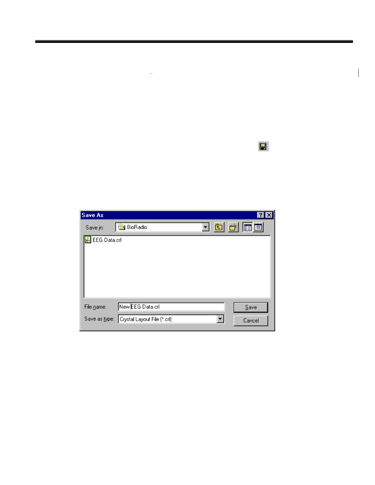
Saving Collected Data
After you have collected your data, made adjustments to the display graph and filters, and/or added any
annotations you can save file.
Capture records the acquired data into a binary data file for off-line viewing and analysis.
Save the data to a file by:
Clicking the SaveCurrent File button on the Main Toolbar , or
Selecting Save Data to File... from the File menu.
The Save Data to File dialog window appears, allowing you to specify the name, format, and location of
the file.
Note: Capture supports opening of older BioRadio Data files (*.bd), however saving changes will require
converting the file to the Crystal File format (*.crl,*.crd). See Converting BioRadio Data Files on page 31.
25
CleveMed Proprietary
Information
Cleveland Medical Devices Inc. RatPaak™ User’s Guide
Chapter 2: Reviewing Data
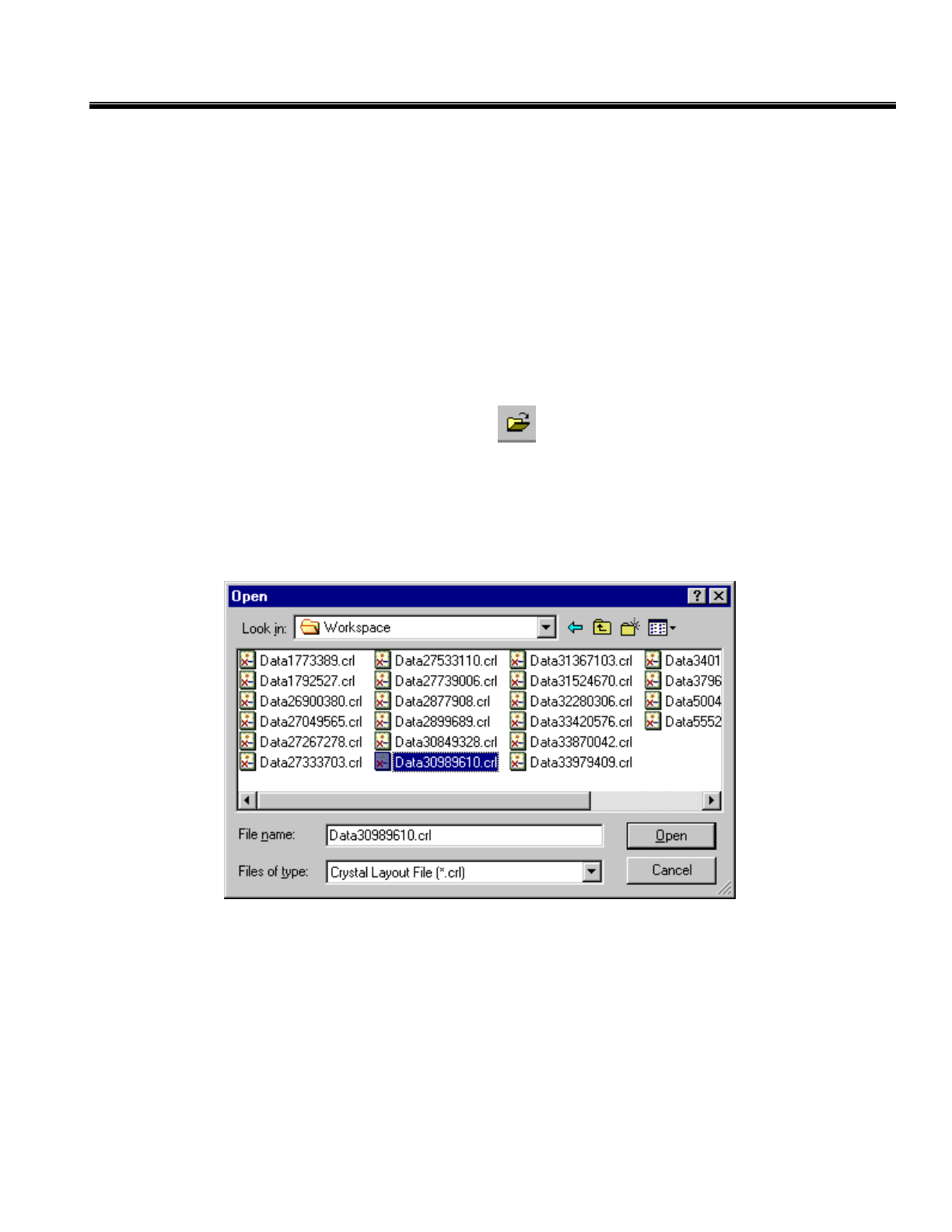
Viewing Saved Files
Once a data file has been recorded, it can be played back. During the playback, it can be annotated or the
display settings can be changed, just as during the recording. In order to save these changes to the file, you
must click on save before opening another file or beginning a new recording session.
A file can be opened by:
Clicking the Open button on the Main Toolbar , or
Selecting Open ... from the File menu.
This displays the Open Data File dialog window, where you browse to find the file or type in the name of
the file you wish to review.
File Formats
The standard format for files in Capture v.2.0 is the Crystal Layout file format. This consists of a Crystal
Layout file (*.crl extension) and a Crystal Data file (*.crd extension). Data files recorded with a previous
version of Capture use the BioRadio Data format (.bd extension). In order to save changes to these files in
Capture 2.0, they must be converted to the Crystal format.
26
CleveMed Proprietary
Information
Cleveland Medical Devices Inc. RatPaak™ User’s Guide
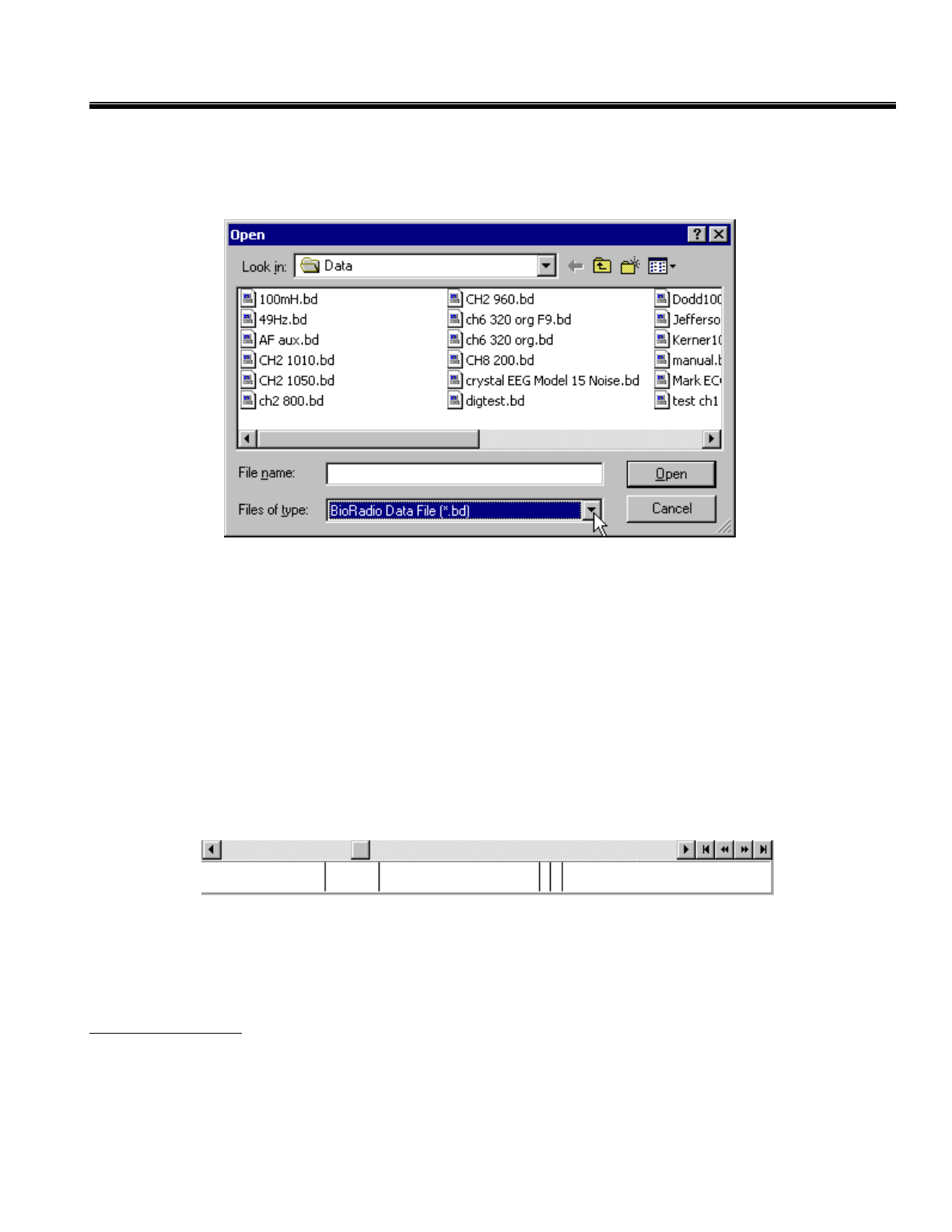
BioRadio Data Files
To open a BioRadio Data file, select Open from the File menu. Under the Files of Type drop-down box in
the Open window, select "BioRadio Data File (*.bd)" to show the available BioRadio Data files.
Select the file you wish to open and click the Open button. The data will be displayed as a normal Crystal
Data file. To save changes to a BioRadio Data File, see “Converting BioRadio Data Files” on page 31.
Changing the Display
Viewing saved data is similar to viewing the data in Capture Mode. All of the display features and
commands can be customized in the same way. Refer to Chapter 3, ‘Recording Physiological Data’ or
Chapter 5, ‘RatPaak Command Reference’.
Searching through Data
When reviewing saved data, you can use the scroll bar that appears at the bottom of the Display Graph to
browse through the file. This scroll bar represents the entire length of the data file, and the scroll bar button
represents the current view position of the data file.
You can click and drag on the scroll bar thumb to quickly move within the recorded data file and search for
particular epochs of data. Clicking on the button to the left of the thumb causes you to move backwards
through the file slowly. The buttons to the right of the thumb, in order from left to right, replicate the
behavior of the navigation controls on the Main Toolbar.
Navigation Controls
Jump to Beginning: moves the display to the beginning of the data file.
Page Backward: moves the display back one page (page size dictated by the Timescale setting.)
Page Forward: moves the display forward one page (page size dictated by the Timescale setting.)
Jump to End: moves the display to the end of the data file.
27
CleveMed Proprietary
Information
Cleveland Medical Devices Inc. RatPaak™ User’s Guide
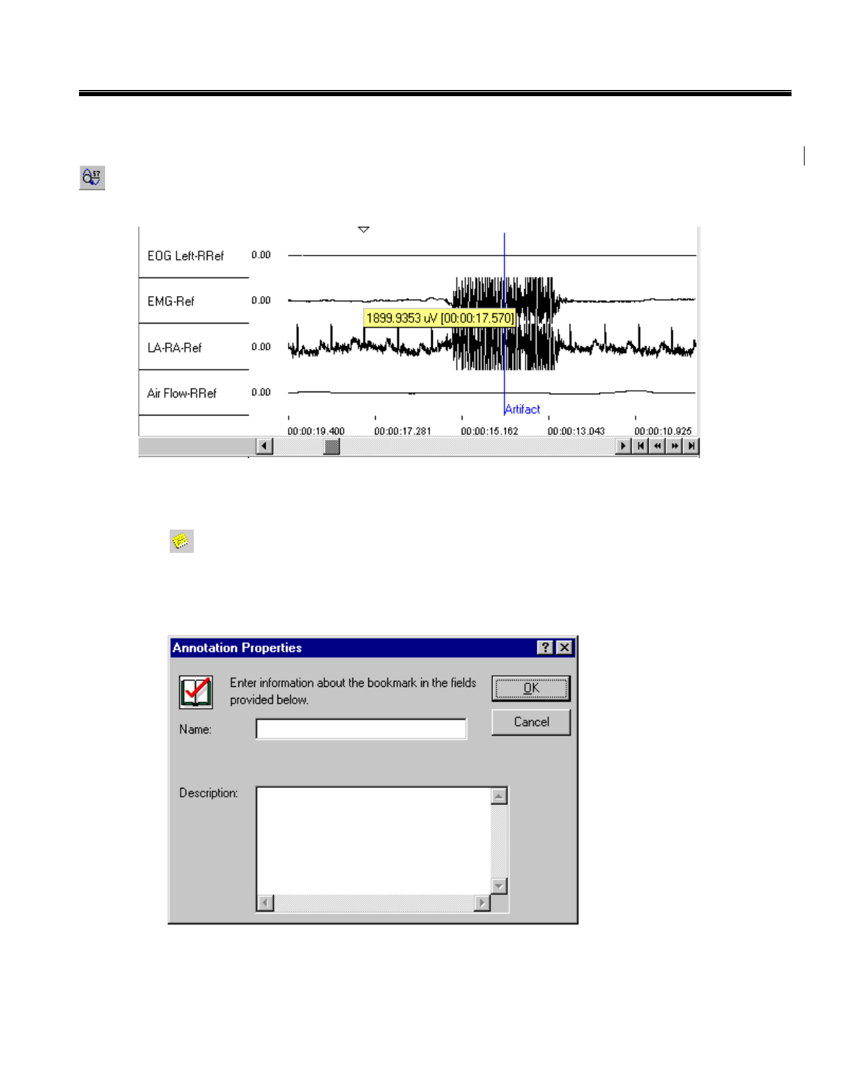
View Data Mode
To enter View Data Mode,select View Data from the Tools Menu or click on the View Data Mode button
on the Main Toolbar. Click on the trace of any channel, hold down the left mouse button, and drag it
back and forth. A label will appear showing the time and output voltage of that position on that waveform.
Annotation Mode
To enter "Annotation Mode" select Annotation Mode from the Tools Menu or click on the Annotation
Mode button on the Main Toolbar.
This mode allows you to add, edit, move, or delete annotations. In order to add an annotation, double-click
in the Display Graph where you would like the annotation to be placed. The Annotation Properties
Window will appear.
Give an appropriate label for the new annotation by typing it in the Name field. You may give more
meaning to the annotation by filling in the details within the Description field. Once you have completed
filling out the properties, click the OK button to insert the annotation.
28
CleveMed Proprietary
Information
Cleveland Medical Devices Inc. RatPaak™ User’s Guide
To edit an existing annotation, click on the annotation label that you wish to edit. Then select Properties
from the Edit Menu. The Annotation Properties Window will appear and you may make your changes.
You can also move an annotation from one part of the file to another. To do this, the Capture software uses
the Cut, Copy, and Paste commands (available from the Edit Menu). When you Cut an annotation, it is
removed from the original position, allowing you to Paste it into a new position. Copy leaves the original
annotation alone, and allows you to paste an identical annotation into a new position. Once you have either
cut or copied an annotation, you may paste copies of it into as many positions as you would like.
You may also "Drag and Drop" an annotation. This has the same effect as a cut and paste combination.
To drag an annotation, click on it with the left button of your mouse, and move the cursor to the desired
destination while holding the left mouse button. When you release the button, the annotation will be
dropped, or moved to the new location. This is most efficient when you only need to move an annotation
to another place already on the screen.
29
CleveMed Proprietary
Information
Cleveland Medical Devices Inc. RatPaak™ User’s Guide
Saving Changes
After you have annotated your file, you can save the changes. Capture records the acquired data into a
binary data file for off-line viewing and analysis.
Save the data to a file by:
Clicking the Save Current File button on the Main Toolbar, or
Selecting Save from the File menu.
Save the current file to a different file name by:
Selecting Save As from the File menu.
The Save As dialog box will appear.
Enter the name by which to save the file and click the Save button.
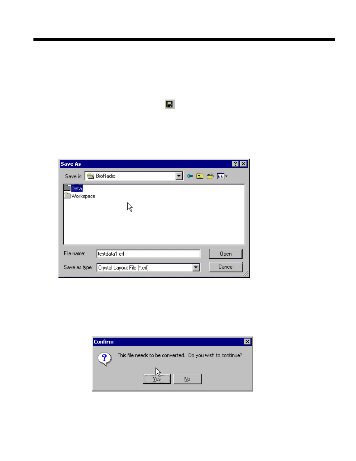
Converting BioRadio Data Files
In order to save any changes made to a BioRadio Data File (*.bd), the file must first be converted to the
Crystal file format. Begin by selecting Save from the File Menu. A confirmation dialog box will appear.
To continue with the file conversion, click the Yes button. The Save As dialog box will appear. Enter the
name by which to save the file and click the Save button. Please note that the default name is that of the
30
CleveMed Proprietary
Information
Cleveland Medical Devices Inc. RatPaak™ User’s Guide
original BioRadio data file with the extension converted to *.crl. Saving with this name will not overwrite
your original file.
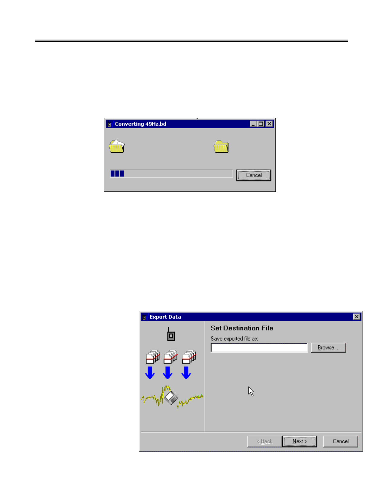
The conversion window that appears has a progress indicator to indicate the conversion process.
Depending on the size of the file, the conversion time may vary from a few seconds to several minutes.
Once the conversion is complete, you will be asked to again confirm the changes to your file, just as when
saving any other file. Click the Yes button, and the process is complete.
Exporting Data
Exporting data translates a data file to an alternate format that other programs can import. The data can be
exported to ASCII data in column format. In View Mode, you can export all or part of the current data file
to a space-delimited ASCII data file, which can be read by programs such as Microsoft Microsoft Excel,
Matlab®, etc. You can select any of the physiological channels to be exported to the ASCII data file, so
that only data of interest is exported. This flexibility greatly reduces unnecessary time spent analyzing
irrelevant data and saves file space.
Note: that only the raw data (as acquired by the Transmitter) is exported. Any viewing options (such
viewing range, filters, etc.) are not reflected in the exported data file.
Begin exporting a file by:
Selecting Export from the
File Menu.
On the Set Destination File page,
choose the name and path for the
ASCII file that will be created.
You can either type in the name
and path in the box labeled “Save
exported file as:" or click on the
Browse button to browse for a
directory and type in a file name.
Once you have selected a name
and path for the ASCII file to be
created, click on Next.
31
CleveMed Proprietary
Information
Cleveland Medical Devices Inc. RatPaak™ User’s Guide
The Export Data dialog windows allow you to select the time interval and channels that will be exported to
an ASCII data file from the saved physiological data you are currently viewing.
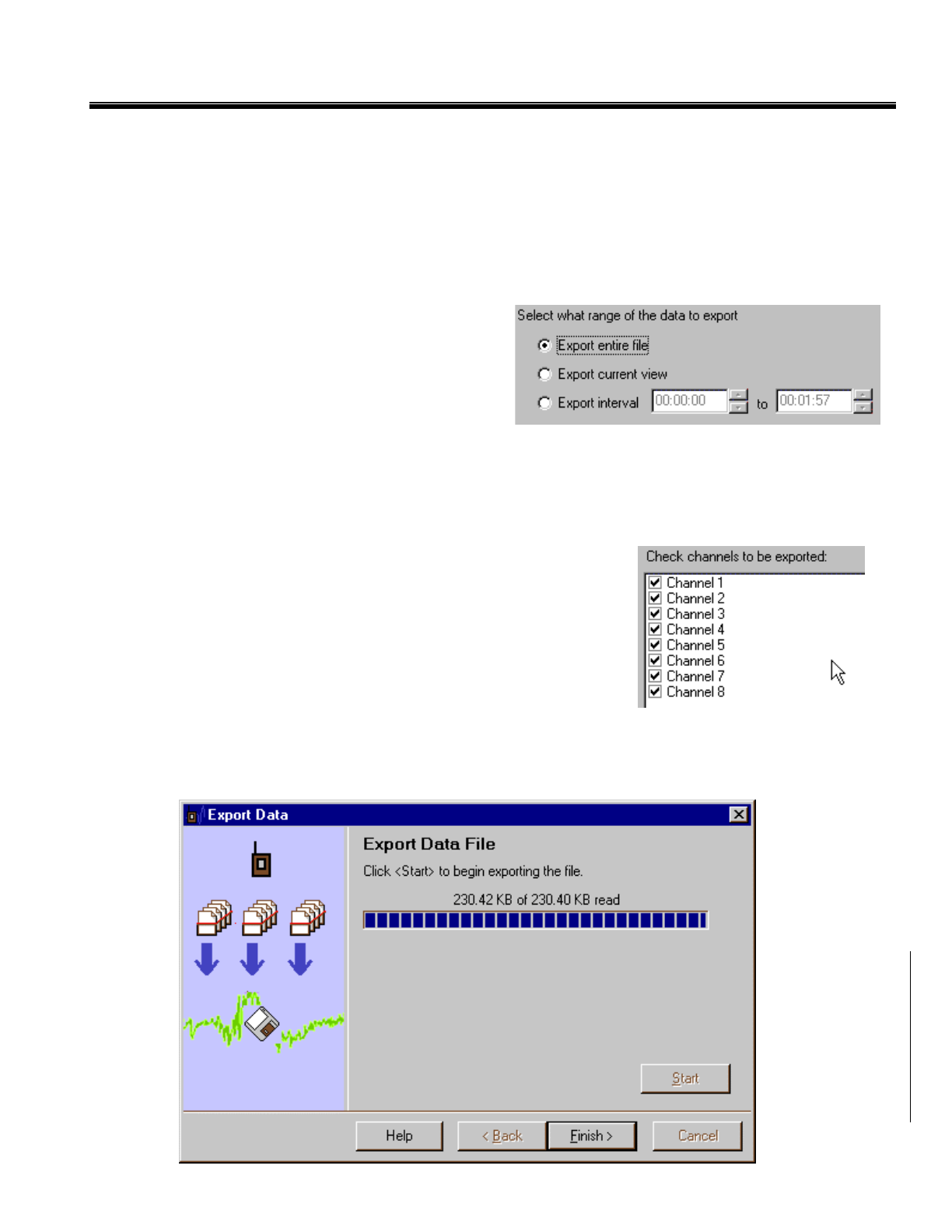
On the Select Export Range page, you select the interval of time that will be exported to the ASCII data
file:
• Export entire file: Exports the entire duration of the data file.
• Export current view: Exports only the duration of
the data file that is visible in the Display Graph
based upon the settings for Timescale and the
starting position.
• Export interval: Exports the duration of the data
file as set by the start and end input boxes, in
hours, minutes, and seconds (HH:MM:SS). You can use the up/down arrows to change the start and
end values, or you can type the times into the input boxes.
Once you have selected the time interval you wish to export click on Next.
On the Select Export Channels page, you can select which of the
input channels will be exported to the ASCII data file. Only channels
with a check mark will be written to the ASCII data file. The channels
will be written in the order they are displayed in this list. Once you
have selected the channels to be exported, click the Next... button to
begin exporting the data file.
On the Export Data File page, click the Start button to begin exporting the data file. A progress bar will
display the export progress. Note that, for large data files, this may take several minutes to complete. Once
exporting has completed, click Finish to return to the main application.
32
CleveMed Proprietary
Information
Cleveland Medical Devices Inc. RatPaak™ User’s Guide
Printing Data
You can print the currently displayed (screen view only) physiological data to
any Windows printer. The printed output is time/date stamped including the
timescale and sampling frequency of the data segment printed.
Click Print from the File menu
The grid lines will be printed unless they are hidden in the Display Graph.
33
CleveMed Proprietary
Information
Cleveland Medical Devices Inc. RatPaak™ User’s Guide
Chapter 3: Capture Command Reference
This chapter provides a brief summary of the commands in RatPaak Capture.
File Menu
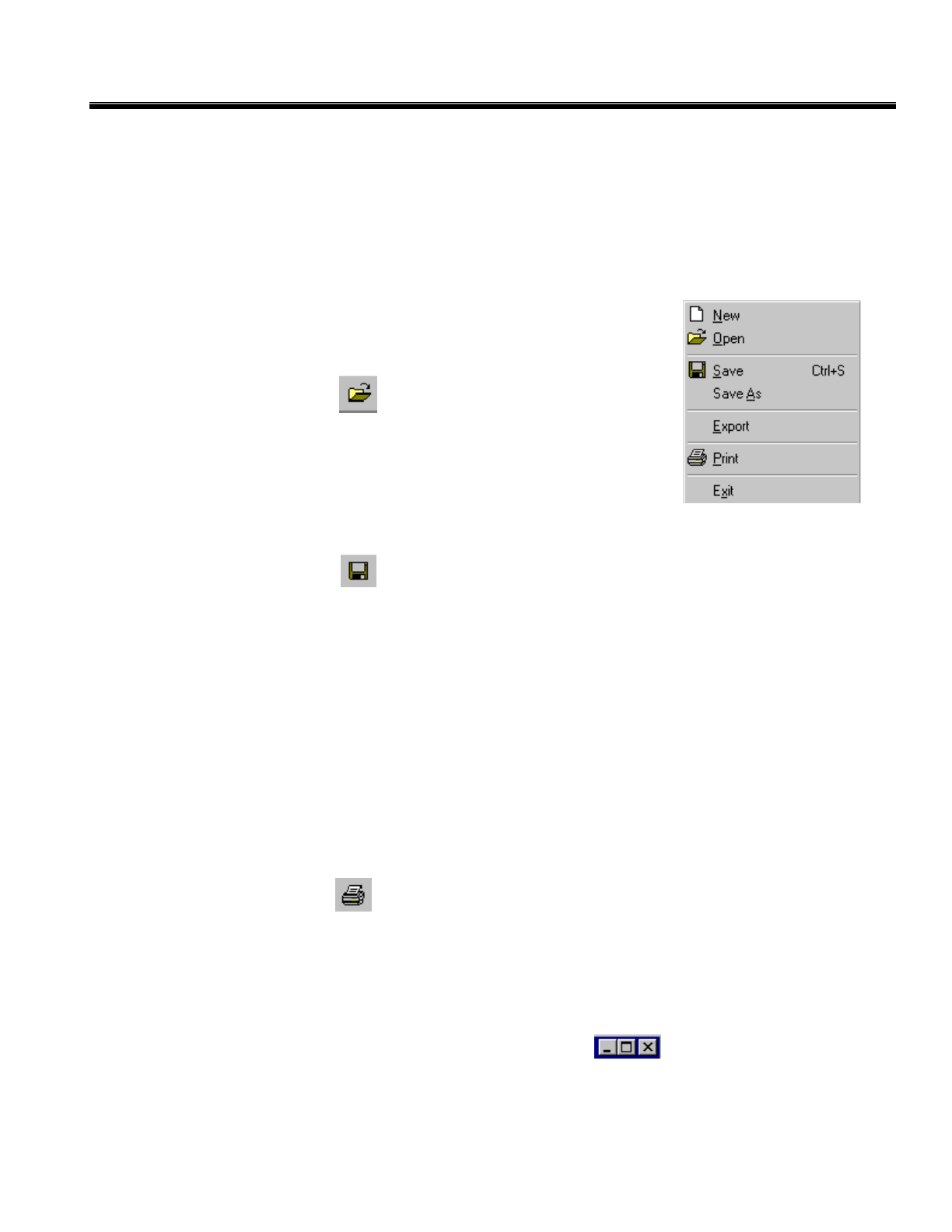
Open Data File…
Open a saved file by:
Clicking the Open button on the Main Toolbar, or
Opening the File menu and selecting Open, or
Keyboard Strokes: “Alt+F”, then “O”.
Save Data to file...
Save your data to a file by:
Clicking the Save button on the Main Toolbar, or
Opening the File menu and selecting Save, or
Keyboard Strokes: “Alt+F”, then “S”.
Export Data File
Export your data to a different file format by:
Opening the File menu and selecting Export, or
Keyboard Strokes: “Alt+F”, then “E”.
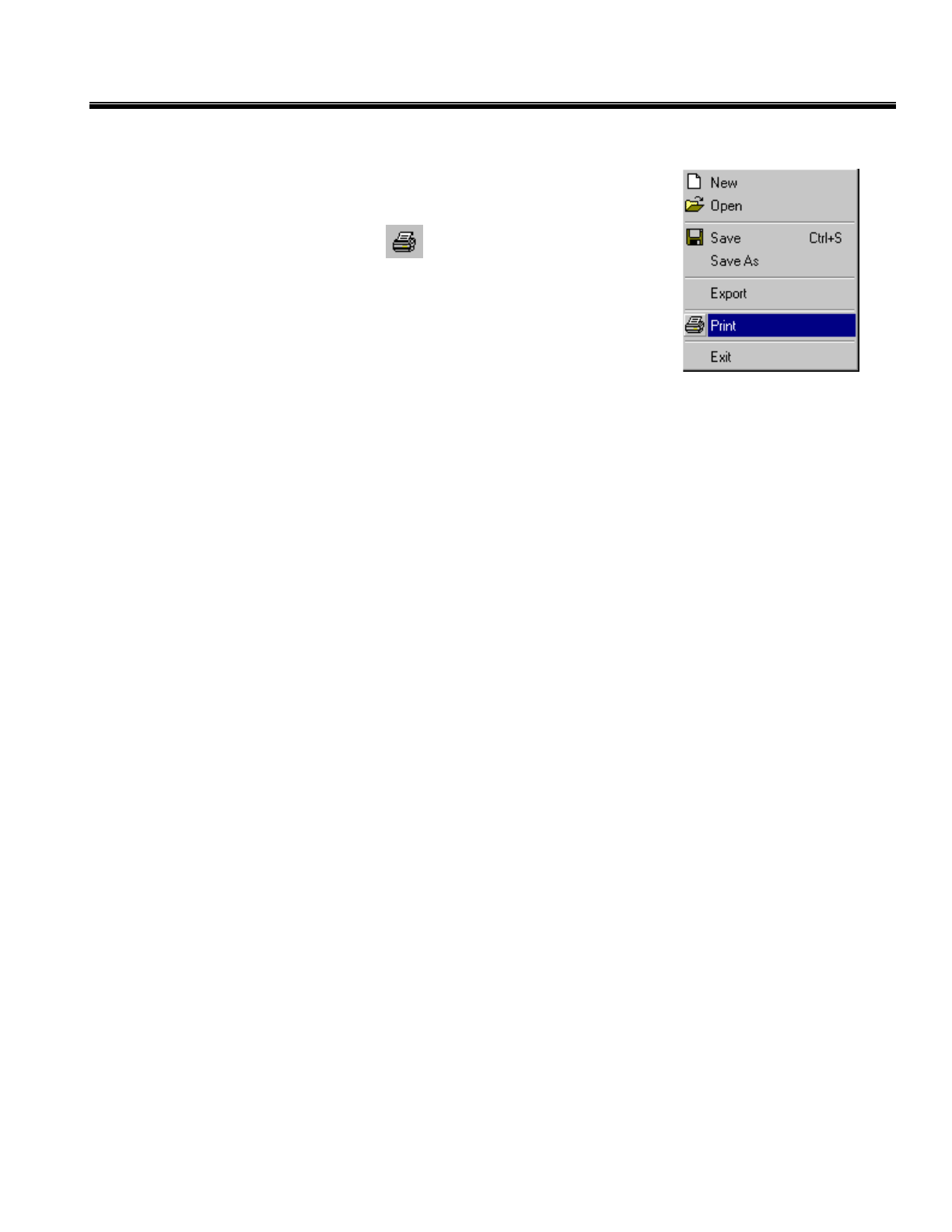
Print
Print your data by:
Clicking the Print button on the Main Toolbar, or
Opening the File menu and Clicking Print or
Keyboard Strokes: “Alt+F”, then “P”.
Exit Capture
Clicking on the X in the upper right corner of the screen, or
Opening the File menu and Clicking Exit, or
Keyboard Strokes: “Alt+F”, then “X”.
34
CleveMed Proprietary
Information
Cleveland Medical Devices Inc. RatPaak™ User’s Guide
View Menu
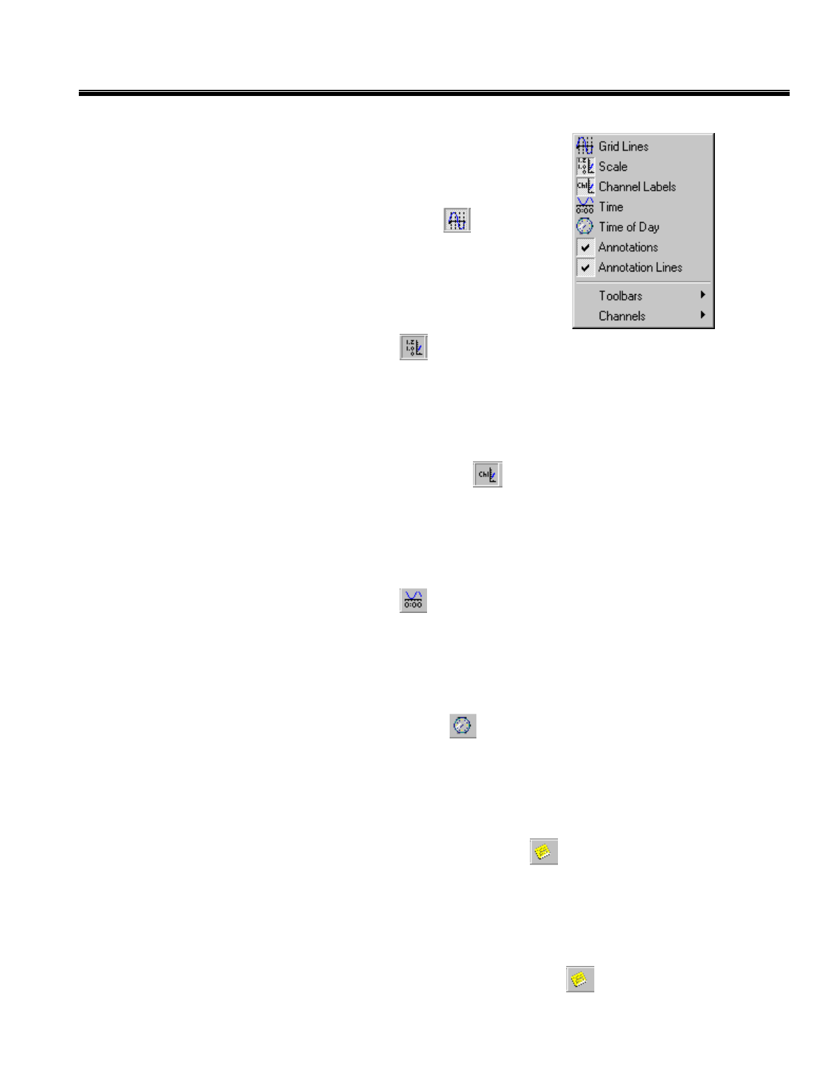
Showing/Hiding the Grid
Show or hide the grid on the Display Graph by:
Clicking the Grid Lines button on the Toolbar, or
Placing a checkmark next to GridLines on the View menu.
Showing/Hiding the Scale
Show or hide the scale on the Display Graph by:
Clicking the Scale button on the Toolbar, or
Placing a checkmark next to Scale on the View menu.
Showing/Hiding the Channel Labels
Show or hide the channel labels on the Display Graph by:
Clicking the Channel Labels button on the Toolbar, or
Placing a checkmark next to Channel Labels on the View menu.
Showing/Hiding the Timeline
Show or hide the time on the Display Graph by:
Clicking the Time button on the Toolbar, or
Placing a checkmark next to Time on the View menu.
Switching Between Elapsed Time and Time of Day
Show or hide the time of day on the Display Graph by:
Clicking the Time of Day button on the Toolbar, or
Placing a checkmark next to Time of Day on the View menu.
Showing/Hiding the Annotations
Show or hide the annotations on the Display Graph by:
Clicking the Show/Hide Annotations button on the Toolbar, or
Placing a checkmark next to Annotations on the View menu.
Showing/Hiding the Annotation Lines
Show or hide the annotation lines on the Display Graph by:
Clicking the Show/Hide Annotation Lines button on the Toolbar, or
35
CleveMed Proprietary
Information
Cleveland Medical Devices Inc. RatPaak™ User’s Guide
Placing a checkmark next to Annotation Lines on the View menu.
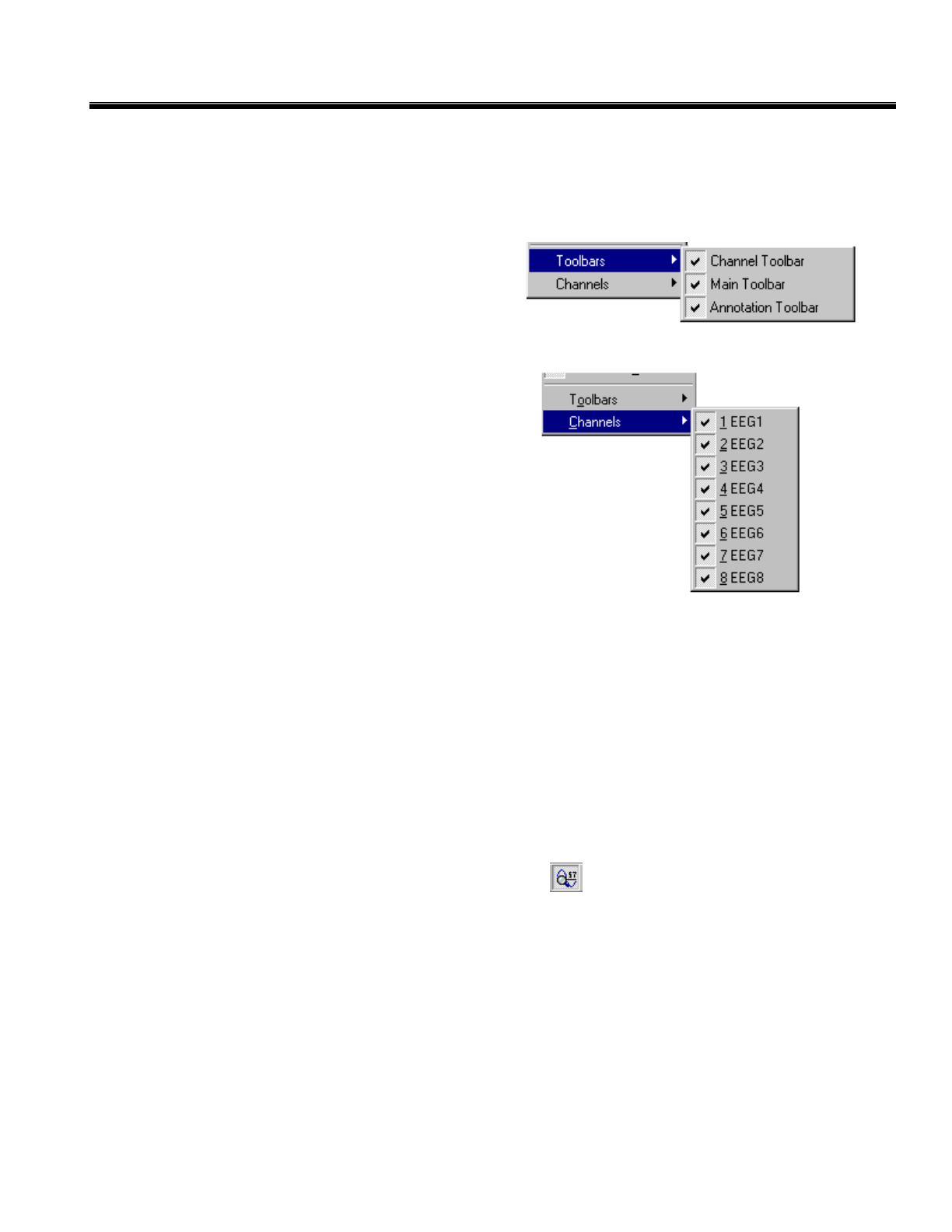
Showing/Hiding the Toolbars
Show or hide the toolbars on the Display Graph by:
Placing a checkmark next to Main Toolbar,
View Toolbar, or Annotation Toolbar under
Toolbars on the View menu.
Showing/Hiding the Channels
Select channels to view during capture/playback by:
Selecting Channels from the View menu, or
Keyboard strokes: “Alt+V” then “C”.
Check/un-check the channels you would like to see in the
DisplayGraph.
Tools Menu
View Data Mode
Get the time and value of a data point while dragging your mouse pointer over a trace. Enter View Data
Mode by:
Opening the Tools menu and selecting View Data Mode, or
Keyboard Strokes: “Alt+T”, then “V”.
Annotation Mode
Work with your annotations interactively with Cut, Copy, Paste and Drag and Drop features. Enter
Annotation Mode by:
Clicking the View Data Mode button on the Toolbar, or
Opening the Tools menu and selecting Annotation Mode, or
Keyboard Strokes: “Alt+T”, then “A”.
Capture Options
36
CleveMed Proprietary
Information
Cleveland Medical Devices Inc. RatPaak™ User’s Guide
The Capture Options dialog allows you to configure how the Transmitter acquires and displays data.
Access the Capture Options dialog by:
Opening the Tools menu and Clicking Options
Or
Keyboard Strokes: “Alt+T”, then “O”.
Transmitter Configuration
Allows the user to specify the
configuration of the Transmitter.
A custom configuration can be
created using the Configuration
Wizard.
Receiver Port
Allows the user to specify the
COM port to which the Receiver
is attached. The default is
COM1, but you can change this if
you have the Receiver attached to
a different port.
37
CleveMed Proprietary
Information
Cleveland Medical Devices Inc. RatPaak™ User’s Guide
Record and Playback of Data
Preview Live Data
View live data without storing it to disk.
Clicking the Preview Data button, on the Main Toolbar .
Record Live Data
Begin capturing live data to disk:
Clicking the Record Data
button, on the Main Toolbar
.
Navigation Controls
The following toolbar buttons provide convenient navigation functions to aid in reviewing data files:
Jump to Beginning: moves the display to the beginning of the data file.
Page Backward: moves the display back one page (page size dictated by the Timescale
setting.)
Page Forward: moves the display forward one page (page size dictated by the Timescale
setting.)
Jump to End: moves the display to the end of the d
Playback Saved Data
View smooth scrolling data as previously captured by:
Clicking the Playback Data button on the Main Toolbar
Adjust the playback speed by moving the Speed control slider in the main toolbar
38
CleveMed Proprietary
Information

Cleveland Medical Devices Inc. RatPaak™ User’s Guide
Glossary
ASCII (American Standard Code for Information Inter-exchange)
A standard character set and coding scheme used to represent letters, numbers, symbols, and control
characters.
Bandwidth
The required capacity for the data volume and transmission rate.
Baud Rate
The number of signal elements per second occurring on a communications channel. Since a signal element
can represent more than one bit, baud rate is not necessarily the same as bits per second.
BPS
The number of bits that are transmitted in one second. This is the basic unit of measure for serial data
transmission.
ISM Band (Industrial, Scientific, and Medical)
In the mid 1980s, the FCC provided an unlicensed radio spectrum in the ISM bands of 902 – 928 MHz,
2400 – 2483.5 MHz, and 5725 – 5850 MHz.
39
CleveMed Proprietary
Information

Cleveland Medical Devices Inc. RatPaak™ User’s Guide
Trademark Acknowledgments
RatPaak™ is a trademark of Cleveland Medical Devices Inc., Cleveland, Ohio.
Windows and Excel are trademarks of the Microsoft Corporation.
Matlab is a trademark of The Math Works Inc.
All other products or brand names are trademarks or registered trademarks of their respective companies.
40
CleveMed Proprietary
Information

Cleveland Medical Devices Inc. RatPaak™ User’s Guide
Index
Annotation, 18, 19, 29, 30, 36
Cut, Copy, and Paste, 30
Drag and Drop, 30
Properties Window, 29
Annotation Mode, 15, 29, 37
Annotation Presets, 18
Annotation Properties Window, 30
ASCII, 32, 33, 40
Batteries, 10
BioRadio Data Files, 26, 27, 28, 31, 32
Capture, 6, 22
Capture Options, 37
Capture Software, 11
Changing the Display, 22, 28
Channel Properties, 23
Custom Settings, 23
Group Settings, 24
Channels, 22
COM port, 16, 17, 20, 21, 38
Connecting the Receiver, 9
Converting BioRadio Data Files, 31
Crystal File format, 26
Display Graph, 13, 21, 22, 23, 24, 28, 29, 33, 34,
36, 37
Edit Menu, 30
EEG, 11, 25
Exit Capture, 35
Exporting Data, 32
File Formats, 27
File Menu, 14, 31, 32, 35
Filter, 16, 23, 25, 26
Grid, 36
group settings, 23, 24
Group Settings, 15, 22, 23, 24
high-pass filter, 25
Installing RatPaak™ Capture Software, 8
Lock, 24
low-pass filter, 25
Main Toolbar, 20, 21, 26, 27, 28, 29, 31, 35, 37,
39
Main Window, 12
Menu Bar, 13
Toolbars, 14
Navigation Controls, 14, 28, 39
Notch filter, 25
Open Data File, 27, 35
Options
Annotation Presets, 18
Device Options, 16
Output File Size, 16
Playback Data, 14, 39
Playback Saved Data, 39
Preview Data, 14, 20, 21, 39
Preview Live Data, 39
Printing Data, 34
RatPaak, 11, 17, 28, 35
Received Signal Strength, 22
Receiver, 6, 11, 16, 17, 20, 21, 38
Receiver Port, 38
Record and Playback of Data, 39
Record Data, 14, 21, 39
Record Live Data, 39
RF Link Status, 16
Save, 14, 26, 31, 32, 35
Saving Changes, 31
scroll bar, 28
Searching through Data, 28
Setting Capture Options, 16
Setting the Receiver Port, 17
Showing/Hiding the Annotation Lines, 36
Showing/Hiding the Annotations, 36
Showing/Hiding the Channels, 37
Showing/Hiding the Toolbars, 37
Status Bar, 16, 20, 22
System Requirements, 7
Test Pack, 20
Time of day, 36
Timeline, 36
Timescale, 15, 16, 24, 33
Toolbars
Main Toolbar, 14
Tools Menu, 29, 37
Transmitter, 6, 11, 12, 16, 17, 20, 21, 32, 38
Transmitter Characteristics, 9
Transmitter Configuration, 17, 38
Uninterruptible Power Supply Usage, 9
View Data Mode, 15, 29, 37
View Menu, 36
41
CleveMed Proprietary
Information