Climax Technology Co 1041RV Medical Emergency Alarm System User Manual CTC 1041RV
Climax Technology Co Ltd Medical Emergency Alarm System CTC 1041RV
Users Manual

c
August 12, 2013

Table of Contents
1. Application Overview________________________________________________________ 1
1.1. Identifying The Parts ____________________________________________________________ 1
1.2. The Power Supply ______________________________________________________________ 2
1.3. Line Capture ____________________________________________________________________ 3
1.4. How to install the Control Panel __________________________________________________ 3
2. Learn-in the Devices ________________________________________________________ 4
2.1. Learning Pendant #1 ____________________________________________________________ 4
2.2. Learning Pendant #2 ____________________________________________________________ 4
2.3. Learning in DECT Devices (CTC-808RV, CP-23 and WTRVS) ________________________ 5
2.4. Removing Pendant #1 & #2 ______________________________________________________ 6
3. System Configuration _______________________________________________________ 7
3.1. Entering Programming Mode ____________________________________________________ 7
3.1.1. Local Programming Mode (Optional) __________________________________________________ 7
3.1.2. Remote Programming Mode __________________________________________________________ 7
3.1.3. CTC-835 Programmer ________________________________________________________________ 8
3.2. Programming Your 1041RV ______________________________________________________ 8
4. Operation _________________________________________________________________ 20
4.1. Idle Mode ______________________________________________________________________ 20
4.1.1. Auto-Answer Incoming Phone Calls __________________________________________________ 20
4.1.2. Non-Emergency Speech Call ________________________________________________________ 21
4.1.3. AC Power Check Up ________________________________________________________________ 21
4.1.4. CTC-1041RV Low Battery ___________________________________________________________ 21
4.1.5. CTC-1041RV Battery Disconnection _________________________________________________ 21
4.1.6. Devices Low Battery ________________________________________________________________ 22
4.1.7. Automatic Check-in Report = Periodic Test Call _______________________________________ 22
4.1.8. Mobility Timer ______________________________________________________________________ 22
4.1.9. No Pendant Present ________________________________________________________________ 23
4.2. Alarm Activation _______________________________________________________________ 23
4.3. Walk Test (Range Test) _________________________________________________________ 27
4.4. Global Test ____________________________________________________________________ 28
4.5. Factory Reset __________________________________________________________________ 28
5. Appendix __________________________________________________________________ 29
5.1. CID Event code ________________________________________________________________ 29
5.2. Tunstall Event code ____________________________________________________________ 30
5.3. Scancom Event code ___________________________________________________________ 30
5.4. CTC-1041RV Programming Command Table _____________________________________ 32
1
1. Application Overview
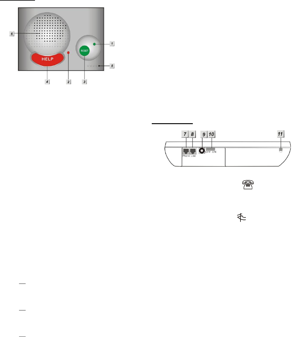
1.1. Identifying The Parts
TOP VIEW
1. GREEN LED
— ON: AC Power is ON.
— FLASH every second: AC Power
failure
— FLASH every 2 seconds: Panel or
Device Low battery
— SLOW FLASH: Line Fault (on and off
at every second)
— QUICK FLASH every 2 seconds:
Supervision failure
2. RED LED
— ON: Off-hook / Waiting retry pause /
Ready to enter Programming Mode
(before entering PIN code)
—
FLASH: Programming Mode /
Pendant Learning Mode
3. GREEN RESET BUTTON
— Press once in normal mode to reset
mobility timer (see command 44)
— Before CTC-1041RV dials out for
alarm reporting, press once to cancel
the alarm reporting
— During or at-the-end of conversation,
press once to terminate two-way
voice communication
— In Programming Mode, press once to
return to Idle Mode
— Press & hold for 3 sec: dial the Non-
Emergency call. (See section 4.1.2.)
— Press & hold for 6 sec: enter
Learning Mode
—
Press & hold for 16 sec: disable
mobility setting
4. RED HELP BUTTON (with backlight)
— Back-lit disigned for easy access at
night
— Backlight illuminates when reporting
and off-hook
— Backlight flashes during the waiting
period until help arrives
5. Microphone
6. Speaker
REAR VIEW
7. Phone Jack marked
—
Telephone unit connection
8. Line Jack marked
— Phone line connection from wall
9. DC Jack
—
DC 12V 1A power adapter
connection
10. Battery Switch
11. Local Programming Telephone
Unit Input
—
A special telephone cord to connect
CTC-1041RV and your phone unit
for Local Programming (optional).
2
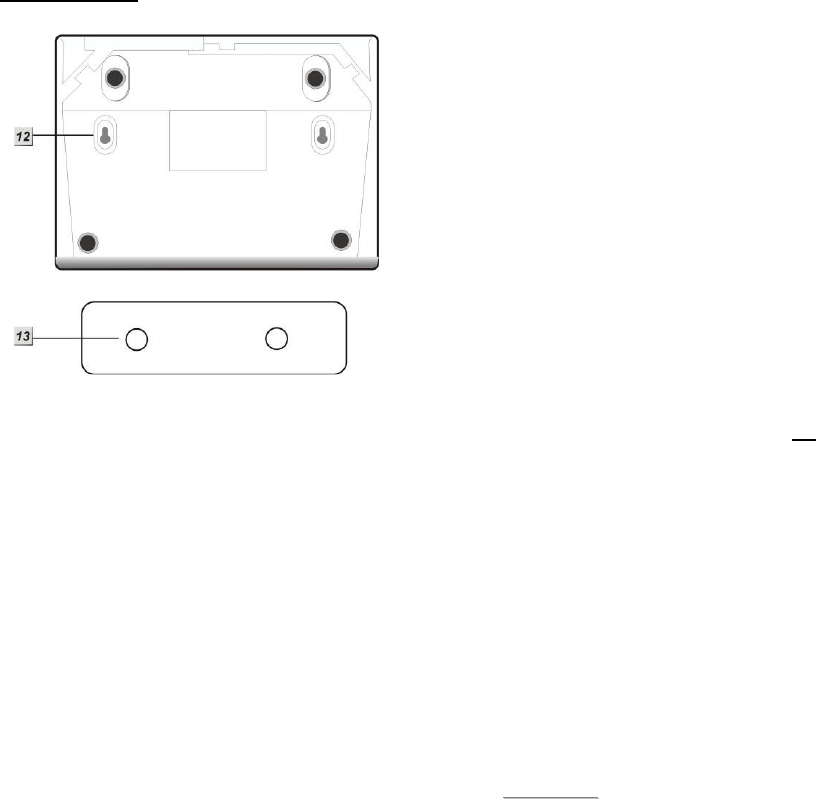
BACK VIEW
12. Mounting Holes
13. Mounting Bracket
1.2. The Power Supply
An AC power adapter is required to
connect to a wall outlet. Be sure only to
use an adapter with the appropriate AC
voltage rating to prevent component
damage. A DC 12V output and 1A adapter
is generally used to power CTC-1041RV.
In addition to the adapter, there is a
rechargeable battery inside CTC-1041RV,
which serves as a back-up in case of a
power failure.
During normal operation, the AC power
adapter is used to supply power to CTC-
1041RV and at the same time recharge
the battery.
It takes approximately 72 hours to fully
charge the battery.
The battery can be manually disconnected
by the battery switch located at the back.
Battery Switch is set as OFF by factory
default, the battery will not be charged
when AC power is connected, nor will it
serve as a back-up power source when
AC power is missing. You need to switch
the battery to ON after supplying AC
power to CTC-1041RV
<
<N
NO
OT
TE
E>
>
Please make sure the battery switch is
slid back to ON position (as marked)
after manually disconnected the
rechargable battery.
3
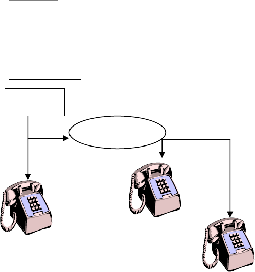
1.3. Line Capture
CTC-1041RV features Master Control
over the telephone line. That means, even
if the phone line is engaged, the CTC-
1041RV has the power to circumvent the
line and dial-out anyway.
<
<N
NO
OT
TE
E>
>
The Line Capture feature is only
available when household phones are
connected after the CTC-1041RV
wiring.
For Example:
CTC-1041RV has the Line Capture function
over TEL #2 and TEL #3, but not TEL #1.
1.4. How to install the Control
Panel
Locating a suitable position for the
Control Panel
The Control Panel requires main power
and a constant telephone connection.
The Control Panel should be easily
accessible.
The Control Panel should not be placed in
a damp location, such as a bathroom.
The Control Panel should not be placed
close to any heat source, such as
microwave ovens, which can reduce
signal strength.
The Control Panel should not be located
alongside other radio transmitting devices,
such as mobile phones, cordless phone,
or wireless computer network (Wi-Fi)
devices.
Important: When drilling into a wall, ensure
there are no hidden cables or pipes.
Mounting the Control Panel
The Control Panel can be mounted on the wall
or wherever desired (e.g. on the table). Ensure
the Control Panel is fitted at approximately
chest height where the buttons, microphone,
and speaker can be easily accessed and
operated.
Use the 2 holes of the Wall Mounting
Bracket as a template, mark off the holes’
positions.
Drill 2 holes and insert the wall plugs if
fixing into plaster or brick.
Screw the base to the wall.
Hook the Control unit onto the Wall
Mounting Bracket (holding the unit with
the front facing you).
Telecom
CTC-1041RV
TEL 1
TEL 3
TEL 2

4
2. Learn-in the Devices
There are two methods to learn in devices:
local learning and command learning. Total
10 sensors are allowed to be learnt into the
system. The combined numbers of DECT
devices (WTRVS, CP-23 and CTC-808RV)
learned into CTC-1041RV can be up to 4.
Local Learning:
You can use the local learning method to
learn in 2 RF devices or 4 DECT devices.
Refer to 2.1. Learning Pendant #1 to learn in
the first RF device, 2.2. Learning Pendant #2
to learn in the second RF device and 2.3.
Learning in DECT Devices to learn in up to 4
DECT devices.
1. The user can turn CTC-1041RV into
learning mode to learn in WTR- Series, Fall
Sensor, WTRVS, CP-23 and CTC-808RV.
2. If you have learned the first device to the
system by following instructions in the 2.1
section, you are not allowed to use
Command 91 (Command Learning) to
learn in another device.
3. If you have learned the second device to
the sytem as instructed in the 2.2 section,
you are not allowed to use Command 92
(Command Learning) to learn in another
device.
Command Learning:
1. The user can use Commands 91-94 to
learn devices into the system. These
devices include PIR Sensor, Smoke
Detector, Panic Button, Carbon
Monoxide Detector, Wrist & Neck
Transmitter, Water Sensor, Pendant
Transmitter, WTR- series, Fall Sensor,
WTRVS, CP-23 and CTC-808RV.
Please refer to 3.2 Programming Your
1041RV: Commands 91-94 for details.
2. Command 91 is designed to learn in
WTR- Series, Fall Sensor, WTRVS, CP-
23 or CTC-808RV only.
3. Command 92 is designed to learn in
WTR- Series, Fall Sensor, WTRVS, CP-
23 or CTC-808RV only.
4. Command 93 is designed to learn in
WTR- Series or Fall Sensor for silent
reporting. Command 93 can also learn
in WTRVS, CP-23 or CTC-808RV, but
WTRVS, CP-23 or CTC-808RV learned
in via Command 93 does not provide
silent reporting (they provide two-way
communication).
5. Command 94 is designed to learn in
the following sensors:
PIR Sensor ----- PIR
Smoke Detector ---- SD
Carbon Monoxide Detector----
CO
Fixed Panic Button ---- PB
Wrist Transmitter ---- WTR
Pendant Transmitter ---- WTR
Water Sensor ---- WS
Fall Sensor ---- FS
Talking Pendant ---- WTRVS
Call Point ---- CP-23
Voice Satellite ---- CTC-808RV
2.1. Learning Pendant #1
Please see the following instructions to learn in
WTR- Series and Fall Sensor.
For Normal Wrist Transmitters (WTR-) or
Fall Sensor
1. Press and hold the RESET button of
CTC1041RV for 6 seconds until you hear
the double beep and followed by a long
beep.
2. The RED LED starts flashing. CTC-
1041RV is now in the learning mode.
3. Press and both the RESET and Pendant
#1 (WTR- Series or Fall Sensor) buttons
simultaneously until CTC-1041RV emit a
double-beep.
4. Pendant #1 has been learnt-in
successfully.
5. Press the Reset & Help button at the
same time to exit the learning mode. The
RED LED will dim to indicate that the
system is back to idle mode.
2.2. Learning Pendant #2
Please see the following instructions to learn in
the second device (WTR- Series and Fall
Sensor).

5
For Normal Wrist Transmitters
(WTR-) or Fall Sensor
1. Press and hold the RESET button of
CTC1041RV for 6 seconds until you hear
the double beep and followed by a long
beep.
2. The RED LED starts flashing. CTC-
1041RV is now in the learning mode.
3. Press and both the HELP and Pendant
#1 (WTR- Series or Fall Sensor) buttons
simultaneously until CTC-1041RV emits a
double-beep.
4. Pendant #2 has been learnt-in
successfully.
5. Press the Reset & Help button at the
same time to exit the learning mode. The
RED LED will dim to indicate that the
system is back to idle mode.
2.3. Learning in DECT Devices
(CTC-808RV, CP-23 and
WTRVS)
CTC-1041RV can learn in 4 DECT devices
at most. The DECT devices will be
automatically assigned to Zone 1~Zone 10
except Zone 3.
Learning in CTC-808RV
1. Press and hold the green reset button of
CTC-1041RV for 6 seconds until you hear
two beeps followed by a long beep.
2. The red LED starts flashing. CTC-1041RV
is now in learning mode.
<
<N
NO
OT
TE
E>
>
CTC-1041RV can learn in 4 DECT
devices at most. If fewer than 4 DECT
devices have been learned into CTC-
1041RV, the red LED will flash slowly to
indicate there are still empty zones for
DECT devices. If CTC-1041RV has
learned 4 DECT devices and there are no
more zones for DECT devices, the red
LED will flash quickly.
You can clear Zone 1 and Zone 2 for
DECT devices to be learned in by
pressing and holding CTC-1041RV’s
green reset button for 6 seconds until you
hear a long beep that indicates the
devices in Zone 1 and Zone 2 have been
simultaneously removed. Now you can
learn DECT devices into Zone 1 and Zone
2.
The above method, however, cannot
create available zones for more DECT
devices if CTC-1041RV has already
learned in 4 DECT devices and none of
them are in Zone 1 or Zone 2.
3. Press and hold CTC-808RV’s learning
button for 5 seconds until you hear 2
beeps. Release the button and CTC-
808RV will emit one short beep to indicate
it is now in learning mode. The green LED
of CTC-808RV is turned on.
4. When CTC-808RV is successfully learned
in, both CTC-1041RV and CTC-808RV will
emit two beeps to indicate the successful
learning. The green LED on CTC-808RV
will be turned off.
<
<N
NO
OT
TE
E>
>
If you do not hear the two beeps and if
CTC-808RV emits one short beep and its
green LED is off and red LED steady on,
that means the learning process has
failed. Please repeat the learning steps
again.
5. Check if CTC-808RV has been learned in
successfully. Press the HELP button on
CTC-808RV and you will hear continuous
beeps from CTC-808RV. When CTC-
808RV beeps, the CTC-1041RV will
respond with 1 beep to indicate that CTC-
808RV is within the operation range.
6. Press the reset and help buttons at the
same time to exit learning mode. The red
LED will dim to indicate that CTC-1041RV
is back to idle mode.
Learning in CP-23 or WTRVS
1. Press and hold the green reset button of
CTC-1041RV for 6 seconds until you hear
two beeps followed by a long beep.
2. The red LED starts flashing. CTC-1041RV
is now in learning mode.
<
<N
NO
OT
TE
E>
>
CTC-1041RV can learn in 4 DECT
devices at most. If fewer than 4 DECT
devices have been learned into CTC-
1041RV, the red LED will flash slowly to

6
indicate there are still empty zones for
DECT devices. If CTC-1041RV has
learned 4 DECT devices and there are no
more zones for DECT devices, the red
LED will flash quickly.
You can clear Zone 1 and Zone 2 for
DECT devices to be learned in by
pressing and holding CTC-1041RV’s
green reset button for 6 seconds until you
hear a long beep that indicates the
devices in Zone 1 and Zone 2 have been
simultaneously removed. Now you can
learn DECT devices into Zone 1 and Zone
2.
The above method, however, cannot
create available zones for more DECT
devices if CTC-1041RV has already
learned in 4 DECT devices and none of
them are in Zone 1 or Zone 2.
3. Press and hold the CP-23/WTRVS button
for 8 seconds until you hear a long beep.
The red LED of CP-23/WTRVS is turned
on. CP-23/WTRVS is now in learning
mode.
4. Now the LED of CP-23/WTRVS turns from
red to green. The green LED blinks. The
Control Panel will emit two quick beeps.
Afterwards CP-23/WTRVS will emit one
beep and its green LED will be turned on
and then go off instantly. CP-23/WTRVS
has been successfully learned in.
<
<N
NO
OT
TE
E>
>
You cannot learn in the same CP-
23/WTRVS twice.
5. Check if CP-23/WTRVS has been learned
in successfully. Press the CP-23/WTRVS
button and you will hear continuous beeps
from CP-23/WTRVS. When CP-
23/WTRVS beeps, the CTC-1041RV will
respond with 1 beep to indicate that CP-
23/WTRVS is within the operation range.
6. Press the reset and help buttons at the
same time to exit learning mode. The red
LED will dim to indicate that CTC-1041RV
is back to idle mode.
2.4. Removing Pendant #1 &
#2
CTC-1041RV can be programmed to remove
Pendant #1 & #2 by Commands 80, 81 or 82.
Please refer to 3.2 Programming Your
1041RV: Commands 80, 81 or 82 for details.
To remove WTRVS, CP-23 and CTC-808RV,
you have to remove it from the Control Panel.

7
3. System Configuration
3.1. Entering Programming
Mode
Three CTC-1041RV programming modes are
available: Local Programming Mode, Remote
Programming Mode, and via CTC-835
Handheld Programmer (sold separately).
3.1.1. Local Programming Mode
(Optional)
From Idle mode, follow the steps below to
enter Local Programming mode.
Step 1. Plug in the telephone set into
LOCAL PROGRAMMING jack
located on the rear side of CTC-
1041RV.
Step 2. Pick up the handset.
RED LED lights up.
Step 3. Enter default ACCESS CODE, 1111
followed by #.
Step 4. CTC-1041RV will emit 2 short beeps
and the red LED starts to flash,
indicating it is in Programming Mode.
Step 5. Proceed to program system by
referring to the Commands in section
3.2 Programming Your 1041RV.
<
<N
NO
OT
TE
E>
>
Local programming is prohibited when
AC Power fails.
The first digit of Access Code must be
entered within 15 seconds, otherwise
CTC-1041RV will exit automatically.
To exit Programming mode, enter 99
followed by #, or place the handset
on hook, or disconnect the
Programming telephone set.
3.1.2. Remote Programming Mode
To allow Remote Programming, there are two
options for CTC-1041RV to answer the
incoming calls.
(1) Auto Answering by ring count
(2) Dial in twice (Ring Count disable)
The two options are set by Command #41.
Please refer to Command 41 under section
3.2 Programming your 1041RV.
3.1.2.1. Auto Answering by Ring Count
By using Command 41, you can set the
number of rings for CTC-1041RV to answer
(20-Rings is set as factory default).
Step 1. Dial CTC-1041RV and wait for CTC-
1041RV to answer.
Step 2. Enter 1111 (default 4-digit Access
Code) followed by #, via the phone set.
Step 3. CTC-1041RV will respond with two
quick beeps to indicate it is ready for
Remote Programming. The RED LED
will flash as a visual indication.
Step 4. You are now in Programming Mode.
Proceed to program by referring to the
Command in section 3.2
Programming Your 1041RV.
3.1.2.2. Dial in Twice (Ring Count Disable)
If 00 is set in Command 41, it means CTC-
1041RV is disabled to auto answer the
incoming calls by ring count. If Remote
programming is required, you will need to call
CTC-1041RV twice.
Step 1. Dial CTC-1041RV and hang up after
first 2 rings, wait for another 8-20 sec
then call again. CTC-1041RV will
answer the call on the first ring. You
will enter the Remote Programming
Mode after the first ring from the 2
nd
call.
Step 2. Enter 1111 (the default 4-digit Access
Code) followed by #, via the phone set.
Step 3. CTC-1041RV will respond with two
quick beeps to indicate it is ready for
Remote Programming Commands.
The RED LED will flash as a visual
indication.
Step 4. You are now in Programming Mode.
Proceed to program by referring to
the Command in section 3.2
Programming Your 1041RV.
<
<N
NO
OT
TE
E>
>
The first digit of Access Code must be
entered within 15 seconds, otherwise
CTC-1041RV will exit automatically.

8
To exit Remote Programming mode,
enter 99 followed by #.
3.1.3. CTC-835 Programmer
CTC-835 is a powerful local & remote
handheld programming tool (sold separetely)
that features a built-in keypad and LCD display
to help you to program the medical alarm
panels effeciently and conveniently. It also
features Once-for-All Uploading, which
allows you program on a computer via the
supplied Pilot software and you can then
upload all the settings to the medical alarm
panel simultaneously with a single mouse click.
For detailed usages, please refer to the
Operation Manual of CTC-835 Programmer.
3.2. Programming Your
1041RV
How to enter Commands?
Please make sure CTC-1041RV is in
Programming Mode (RED LED flashes
continuously) before trying any CTC-
1041RV Command Functions. Please refer
to section System Configuration, Entering
Programming Mode.
Follow the protocol below to command
CTC-1041RV:
CC
#
DTMF
ACK
Function
Selection
#
DTMF
ACK
1. 2.
3. 4. 5.
6.
1. CC = 2-digit DTMF Command
2. # = Termination of the DTMF Command
3. ACK = DTMF Command
Acknowledgement from CTC-1041RV
Short beep: Command succeeded
Long beep: Command failed
4. Function Selection = According to
different Command you will have different
entering in this part, e.g. Tel. Number,
Account number, etc.
5. # = Terminates Function Selection
6. ACK = Function Selection
Acknowledgement from CTC-
1041RV
Short beep: Function Selection succeeded
Long beep: Function Selection failed
Follow the Command Steps to program
your CTC-1041RV:
Step 1. Enter Command number (DTMF
Numeric Command, ex. (01), (02)…)
Step 2. Press (#) to terminate the DTMF
Command.
Step 3. One short beep will be heard for
successful Command entry.

9
Step 4. Enter the desired Command function
number.
Step 5. Enter (#) to terminate the Command
Operation.
Step 6. CTC-1041RV will emit a short beep,
indicating successful programming.
The maximum interval between key strokes is
2 minutes. Otherwise, commands will be
ignored and CTC-1041RV will automatically
exit to Idle Mode.
Any erroneous programming must be
rectified and program again correctly.
Command 01-04
Telephone Number Programming
Used to program the 1
st
- 4
th
Tel. numbers
respectively.
To program the 1
st
Tel. number: enter (01)
followed by (#). After one short beep, enter
(telephone number) followed by (#). The
1
st
Tel. number is programmed successfully.
Likewise, the 2
nd
, 3
rd
or 4
th
Tel. numbers can
be programmed using Command (02), (03)
or (04) respectively.
<
<N
NO
OT
TE
E>
>
When entering the phone number,
entering () represent a 3-sec. pause.
(ex. Switchboard system, extension,
etc.)
Up to 20 digits including () are
allowed for each telephone number.
Delete Telephone Number:
::
:
To delete the 1
st
Tel. number, enter (01)
followed by (#), after one short beep, enter
another (#). CTC-1041RV will emit another
short beep, signaling the 1
st
Tel. number is
erased.
Likewise, you can erase the respective 2
nd
,
3
rd
or 4
th
Tel. Numbers, by following the
above procedure.
Command 05-06
Select Telephone Number for Alarm
Reporting and Status Reporting
<
<I
IM
MP
PO
OR
RT
TA
AN
NT
T
N
NO
OT
TE
E>
>
If the Tel. number is selected in
Commands #5, #6 and #7, then
Command #7 holds the top priority to
overwrite the setting. The Tel. number
selected in Command #7 will not be
used for alarm and/or status reporting,
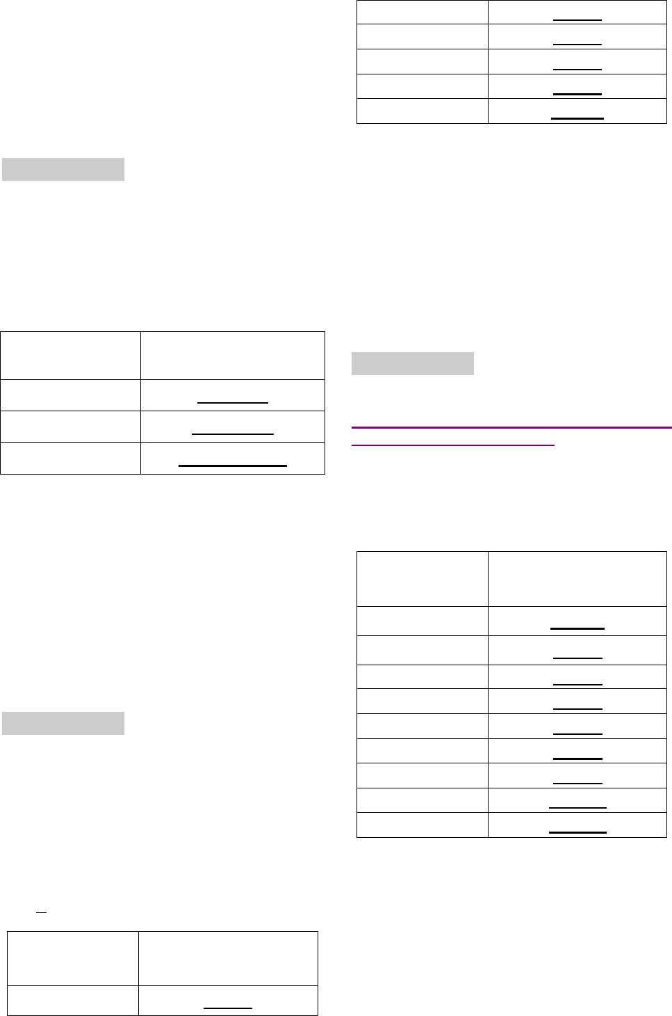
Command (05): Select which telephone
number (1-4) is/are to be used for Alarm
Reporting.
Command (06): Select which telephone
number (1-4) is/are to be used for Status
Reporting.
Available Key-in options:
Tel. Number Function Selection
Sequence
1
st
Tel. # (1)
2
nd
Tel. # (2)
3
rd
Tel. # (3)
4
th
Tel. # (4)
1
st
& 2
nd
Tel. #s (12)
1
st
& 3
rd
Tel. #s (13)
1
st
& 4
th
Tel. #s (14)
2
nd
& 3
rd
Tel. #s (23)
2
nd
& 4
th
Tel. #s (24)
3
rd
& 4
th
Tel. #s (34)
1
st
, 2
nd
& 3
rd
Tel. #s
(123)
1
st
, 2
nd
& 4
th
Tel. #s
(124)
1
st
, 3
rd
& 4
th
Tel. #s
(134)
2
nd
, 3
rd
& 4
th
Tel. #s
(234)
1
st
, 2
nd
, 3
rd
& 4
th
Tel. #s
(1234)
Factory default is set as (1234). Alarm &
Status will be reported to all of 4 Telephone
Numbers.

10
<
<N
NO
OT
TE
E>
>
The Tel. number selected in
Command #7 will not be used for
alarm and/or status reporting, even if it
is selected in command #5 and/or #6.
When multiple Tel. numbers are
selected, CTC-1041RV will always
dial in respective programmed order.
The latest Command (05-06) setting(s)
will overwrite any previously enter
setting(s).
Command 07
Select Telephone Number for Non-
emergency call
This command is used to select which
telephone number will be used for non-
emergency call.
The selected Tel. number will not be used
for alarm and/or status reporting, even if it
is selected in command #5 and/or #6.
Available key-in options:
Tel. Number Function Selection
Sequence
Disable (0)
1
st
Tel. # (1)
2
nd
Tel. # (2)
3
rd
Tel. # (3)
4
th
Tel. # (4)
Factory default is set as (0) disable. Alarm
& Status will be reported to all of 4
Telephone Numbers.
Please refer to section 4.1.2 for more
information.
Command 10-14
Account Number Programming
Commands (10-14) are used to set the
account number for the telephone numbers
used for Digital Reporting.
Command (10): Set the same account
number for all telephone numbers.
Command (11-14): Set the account
numbers for the 1
st
-4
th
Tel. numbers used
for Digital Reporting respectively.
In (Function Selection) key in 4 or 6 digit
Account Number.
Command 20-24
Reporting Method
Commands (20-24) are used to program
the Alarm reporting method for each Tel.
Number.
Command (20): Program the same Alarm
Reporting Method for all 4 Tel. Numbers.
Command (21-24): Program the alarm
reporting method for the 1
st
-4
th
Tel.
Numbers respectively.
Available Options:
Method Function
Selection
Digital
Reporting
Method
(0) Contact ID
(1) Scancom
(2) Tunstall
Speech
Method (3) Open Two-way
communication
(0), Contact ID, is set as factory default for
all 4 telephone Numbers.
<
<N
NO
OT
TE
E>
>
The latest Command (20-24) setting(s)
will overwrite any previously entered
setting(s).
If any of Digital Reporting Methods
is selected:
Once alarm or emergency data is
successfully transmitted, CTC-1041RV

11
will automatically enter specific
Follow-On and/or Call Back Mode as
specified by Command (38).
If Speech Method is selected:
After the dialing for alarm/emergency
trigger is successful, CTC-1041RV
opens a two-way voice communication
between the Call Recipient and CTC-
1041RV for 1-10 minutes (set by
Command #46).
If the Call Recipient needs more talk
time, they can press any keys except
9 on their phone set to add another 1-
10 minutes (set by Command #46).
To terminate the call, press (9) or
RESET BUTTON on CTC-1041RV.
Command 31
Ringer Enable for Incoming Calls
CTC-1041RV can be programmed to emit
a ring tone as an audio alert, or silent for
incoming calls.
Function Selection
Result
(0) OFF
(Ring Tone Disable)
(1) ON
(Ring Tone Enable)
Factory Default is set as (0), OFF.
<
<N
NO
OT
TE
E>
>
If the function is set to ON, you can
answer the incoming call by pressing
the RED HELP BUTTON or Pendant
Button.
The time-out period for the incoming
call is 1 to 10 minutes (set by
Command 46). During the
communication, CTC-1041RV will
emit two beeps via the telephone
handset to alert the call recipient the
remaining time of 20 & 10 sec.
Press any DTMF keys (except
DTMF#9) can extend another 1 to 10
minutes (set by Command 46)
To terminate the incoming call: (1)
press the green reset button on CTC-
1041RV; or, (2) press DTMF #9 from
the call recipient’s end.
Command 32
Audible Fault Alert
CTC-1041RV can be programmed to emit
detected and existent Fault Alert Beeps at
every 30 sec.
Function Selection
Result
(0) OFF
(No Warning Beep)
(1) ON
(With Warning Beep)
Factory Default is set as (0), OFF.
The fault situations include AC failure, line
failure or battery damage.
Command 33
Help Arrived Signaling
This function is only available for the digital
Contact ID reporting method.
This function will be activated in the
following situations:
When the Red Help Button is pressed.
When the button on WTRVS or Fall
Sensor is pressed.
When a fall is detected.
When Night Switch’s Red Button is
pressed.
It is used for the Monitoring Center
personnel to confirm if the help has arrived
for the user or not.
If Help Arrived Signaling is set to ON, once
the Alarm Reporting is completed, the
RED HELP BUTTON will start to flash.
Press the GREEN RESET BUTTON when
the Help arrives, and CTC-1041RV will
report to monitoring center and the RED
BUTTON will stop flashing.
If Help Arrived Signaling is set to OFF,
once the Alarm Reporting is completed,
CTC-1041RV will return to idle mode.

12
Function Selection
Result
(0) OFF
(Disable)
(1) ON
(Enable)
Factory Default is set as (1), ON.
<
<N
NO
OT
TE
E>
>
If the green RESET button is not
pressed within the period set by
Command 67 (Help Arrived Timer),
CTC-1041RV will send the alarm
report to summon help again and
inform the Monitoring Center that no
help has arrived within the period set
by the Help Arrived Timer.
Command 33 (Help Arrived Signaling)
has to be set as ON for Command 67
(Help Arrived Timer) to be activated.
If help has not arrived after 4 retries,
CTC-1041RV will dial the telephone
number set by Command 75 and open
two-way communication when the call
is answered.
Command 34
Emergency Button Enable
The RED HELP BUTTON can be enabled
or disabled to send an Emergency alarm
report:
Function
Selection Result
(0) OFF
(Deactive)
(1) ON
(Active)
Factory Default is set as (1), ON.
<
<N
NO
OT
TE
E>
>
When this function is programmed as
OFF, the RED HELP BUTTON is
deactivated.
When this function is programmed as
ON, the RED HELP BUTTON is
activated. When pressed, it will send
an Emergency alarm report to the
Monitoring Station.
Command 35
Silent Mode
CTC-1041RV can be selected to operate in
Silent Mode. This will mute all normal
operation warning beeps, key tone and
ring.
<
<N
NO
OT
TE
E>
>
In silent mode, the speaker still
functions normally for two-way voice
communication.
Function
Selection Result
(0) ON
(Silent)
(1) OFF
(Normal)
Factory Default is set as (0), OFF.
Command 37
AC Fault Report
The CTC-1041RV can be programmed to
send a Fault Report when an AC power
failure is detected.
Function Selection
Result
(0) OFF
(Send No Report)
(1) ON
(Send Report)
Factory Default is set as (1), ON.
<
<N
NO
OT
TE
E>
>
Reporting will only be made after a
continuous one hour of AC Fault
condition is detected.

13
Command 38
Follow-On & Call-Back Function
The Command is available for Digital
Reporting Methods (when Command #20 -
#24 is set as (0), (1) or (2).
Function Selection
Result
(0) Follow-On
(1) Call-Back
(2) Follow-On & Call-Back
Factory Default is as (0), Follow-On.
When this function is programmed as (0),
after a successful alarm reporting
(triggered by pressing the Help button on
the Medical Panel) to the Monitoring
Center, CTC-1041RV will automatically
enter the Follow-On mode as specified by
Command (45). If the alarm is triggered by
a Talking Pendant (WTRVS), the system
will automatically enter “Wait for
Command” mode (see Command 45) and
wait for the DTMF 2 signal pressed by the
Monitoring Center to set up two-way
communication between WTRVS, the
Monitoring Center and all CTC-808RVs
learned into the system. If the alarm is
triggered by CTC-808RV, the system will
automatically enter “Wait for Command”
mode (see Command 45) and wait for the
DTMF 2 signal pressed by the Monitoring
Center to set up two-way communication
between the Monitoring Center and all
CTC-808RVs learned into the system.
When this function is programmed as (1),
after a successful alam reporting (triggered
by pressing the Help button on the Medical
Panel) to the Monitoring Center, CTC-
1041RV will automatically hang up the line
and start a 5-minute waiting period to auto
answer any incoming phone calls from the
Monitoring Center. The Monitoring Center
personnel should enter an authorized
access code (default: 1111), followed by (#)
to set up the two way communication
between CTC-1041RV and the Monitoring
Center.
If the alarm is triggered by a Talking
Pendant (WTRVS), the system will wait for
an authorized access code (default 1111)
followed by (#) during the 5-minute waiting
period to open two-way communciation
between WTRVS, the Monitoring Center
and all CTC-808RVs learned into the
system.
If the alarm is triggered by CTC-808RV,
the system will wait for an authorized
access code (default 1111) followed by (#)
during the 5-minute waiting period to open
two-way communciation between the
Monitoring Center and all CTC-808RVs
learned into the system.
When this function is programmed as (2),
after a successful alarm reporting
(triggered by pressing the Help button on
the Medical Panel) to the Monitoring
Center, CTC-1041RV will automatically
enter the Follow-On mode as specified by
Command (45). If the alarm is triggered by
a Talking Pendant (WTRVS), the system
will automatically enter “Wait for
Command” mode (see Command 45) and
wait for the DTMF 2 signal pressed by the
Monitoring Center to set up two-way
communication between WTRVS, the
Monitoring Center and all CTC-808RVs
learned into the system. If the alarm is
triggered by CTC-808RV, the system will
automatically enter “Wait for Command”
mode (see Command 45) and wait for the
DTMF 2 signal pressed by the Monitoring
Center to set up two-way communication
between the Monitoring Center and all
CTC-808RVs learned into the system.
Once Follow-On Mode is terminated, CTC-
1041RV will automatically start a 5-minute
waiting period to auto answer any incoming
phone calls from the Monitoring Center. The
Monitoring Center personnel should enter
an authorized access code (default: 1111),
followed by (#) to set up the two way
communication between CTC-1041RV and
the Monitoring Center. If the alarm is
triggered by a Talking Pendant (WTRVS),
the system will wait for an authorized
access code (default 1111) followed by (#)
during the 5-minute waiting period to open
two-way communciation between WTRVS,
the Monitoring Center and all CTC-808RVs
learned into the system. If the alarm is
triggered by CTC-808RV, the system will
wait for an authorized access code (default
1111) followed by (#) during the 5-minute
waiting period to open two-way
communciation between the Monitoring
Center and all CTC-808RVs learned into
the system.
<
<N
NO
OT
TE
E>
>

14
During two-way communication, you
can use DTMF command to switch the
communicating method. Please refer to
section 4.2. Alarm Activation.
The first digit of Access Code must be
entered within 15 sec. Otherwise,
CTC-1041RV will disconnect the call
automatically.
To terminate the call, press DTMF (9)
or RESET BUTTON on CTC-1041RV.
If the 5-minute waiting period is up,
CTC-1041RV will automatically exit
this waiting mode and return to idle
mode.
Command #41 (Auto Answer for
Remote Programming) will not be able
to proceed during the 5-mins Call-
back time.
Command 39
Dialing Mode
This function is for you to select the dialing
method of your telecommunications.
There are two dialing methods available for
user:
Function Selection
Result
0 TONE
1 PULSE
Factory Default is set as (0), Tone.
Command 40
Set Access Code
The Access Code is used to enter
Programming Menu (locally or remotely),
and the Call-Back Function.
It consists of 4 digits and has been set to
(1111) as factory default. Before you set
your own Access Code, (1111) must be
keyed in.
To set a new Access code; enter the
desired (4-digit number) in Function
Selection.
Command 41
Auto Answer for Remote Programming
CTC-1041RV can be programmed to auto
answer incoming phone calls after a pre-
set number of rings have been reached.
The number of rings range from (00) (no
auto answer) to (32) rings.
Function Selection
Result
(00) OFF
(01) - (32) ON
Factory Default is (20) Rings.
<
<N
NO
OT
TE
E>
>
If 00 is selected, it means CTC-
1041RV cannot auto-answer the call
by ring count. If you want to do
Remote programming, please follow
the Remote Programming method
described in System Conifuration, I.
Entering Programming Mode: 2.
Remote Programming Mode.
Command 43
Periodic Test Call
CTC-1041RV can be programmed to make
test calls periodically from (00) (no test call)
to every (1) - (7) or 30 days:
Function Selection
Result
(0) OFF
(1) - (7) 1 - 7 DAYS
(8) 30 DAYS
Factory Default is set as (0), OFF.
<
<N
NO
OT
TE
E>
>
Whenever programming mode is
accessed, CTC-1041RV will reset the
Periodic Test Call timer.
Periodic Test Call will only function
with telephone numbers assigned to
Digital reporting method in Command
20-24.

15
Command 44
Mobility Timer
This function monitors user movement around
the premises and sends an inactivity report to
the Monitoring Center if the user fails to reset
the inactivity timer.
This will disable or enable the Inactivity
Timer with selectable count down periods.
Options are:
Function
Selection Result
(0) DISABLE
(1) 12HR
(2) 24HR
Factory Default is set as (0), DISABLE.
<
<N
NO
OT
TE
E>
>
The Mobility Timer counting down can
be reset by:
1. Pressing the RESET button on
CTC-1041RV, or,
2. Movement detected by PIR
Detector
When Mobility Timer expires and no
reset signal is received, CTC-1041RV
starts to emit one long beep every 5
minutes to alert the user. After 30
minutes, if reset signal is not received,
a mobility alarm reporting will be made.
The reporting method for mobility
alarm is the same as the emergency
alarm. The report will be sent based on
your reporting methods.
When (0) is selected, no code is sent
to Monitoring Center.
When CTC-1041RV is in idle mode,
press and hold the green reset button
for 16 seconds, until you hear a long
beep. Then release the button; the
Mobility function will be disabled.
Command 45
Follow-On Mode Choice
This Command is only available for Digital
reporting with Command #38 set as (0) or
(2).
It is used to select the Follow-On Choice
for CTC-1041RV after it has made a report
to the Monitoring Center.
After reporting, CTC-1041RV can wait for
further commands, or enter a Two-Way
Full Duplex Communication, or Listen-In
Half Duplex Communication immediately
according to the setting under this
command:
Function
Selection Result
(0) WAIT
COMMAND
(1) LISTEN
(2) TWO WAY
Factory Default is set as (2), TWO WAY.
<
<N
NO
OT
TE
E>
>
When (0) is selected, after CTC-
1041RV has made a report to the
Monitoring Center, it will wait for 1-10
minutes (set by Command 46), and
then follows the DTMF commands that
are received from the Central
Monitoirng Station for action.
If no command is received after the
waiting period, the system will
automatically return to Idle mode.
When (1) is selected, after CTC-
1041RV has made a report to the
Monitoring Center, it will automatically
enter Listen-In Half Duplex for 1-10
minutes (set by Command 46) allowing
the Monitoring Center Personnel to
listen in to what is happening on the
other side.
When (2) is selected, after CTC-
1041RV has made a report to the
Monitoring Center, it will immediately
enter a Two-way Full-duplex
Communication mode for 1-10
minutes (set by Command 46), that
gives the user the ability to speak
directly with the Monitoring Center
Personnel.
If either Scancom or Tunstall reporting
format is selected, CTC-1041RV will
ignore Command #45 selections. It will
always open a Two-way voice for
Follow-On choice.
16
If an alarm is triggered by WTRVS or
CTC-808RV, Monitoring Center
personnel will have to press DTMF 2 for
over 1 second to open two-way
communication regardless of the
Follow-On choice you have set.
Command 46
Follow-On Mode & Two-Way Period
This command is used to program the
allowable time duration for Follow-On
mode choice (Commend #45) & Two-way
voice communication period (Speech
mode). It can be set from (01) (1 minute) -
(10) (10 minutes).
Function Selection
Result
(01) 1 MINUTE
(02) 2 MINUTES
(03)-(10) 3-10 MINUTES
Factory default is set as (02) 2 minutes.
The allowable time duration for either Wait
Command, Two-way, Listen-In Only or
Two-way voice comminucation in
Speech mode is two mins. During the 2-
min period, CTC-1041RV will emit two
beeps via the telephone handset to alert
the call recipient the remaining time of 20 &
10 sec. Pressing assigned DTMF key can
extend another 1-10 minute(s).
Command 47
Off-Set Time
After the Control Panel‘s power is supplied,
the time of the Check-in Report starts
calculating.
According to the setting of Off-Set Time,
the Control Panel will send Check-in
Report once, and then send report
according to the setting of Command 43
Test call.
Function
Selection Result
(1) 1 Hour
(2) 2 Hour
(3) 3 Hour
(4)
4 Hour
(5)
8 Hour
(6) 12Hour
Factory default is set as (1) 1 Hour. When
the Off-Set Time is reset in programming
Mode, the time of the Off-Set period will
recalculate.
Off-Set time Report will be sent only once,
and then the Control Panel sends Check-in
Report according to setting of period test
call, unless the Control Panel restarts or
the Off-Set time is reset.
Command 49
Supervision
This function is not available for the digital
Scancom reporting method.
This option is used to enable system
Supervision function. Once enabled, CTC-
1041RV will be able to receive the check-
in signals from Wrist Pendants (WTR-) to
indicate their proper functioning.
Function
Selection Result
(0) Disable
(1) 4 Days
(2) 5 Days
(3) 6 Days
(4)
7 Days
(5)
8 Days
(6) 9 Days
(7) 10 Days
(8) 30 Days
Factory default is set as (0) Disable. No
code is sent to Monitoring Center.
When the supervisory timer expires and no
supervision signal is received from WTR-,
the supervisory alarm reporting will be
made.
The reporting method for supervisory alarm
is the same as the emergency alarm. The
report will be sent based on your reporting

17
methods.
The supervision function does not cover
WTRVS.
Command 66
Set Guard Time Delay Time for Fall
Sensor
This command is used to set the guard
time delay time for fall sensor.
CTC-1041RV can be programmed to delay
alarm reporting (triggered by Fall Sensor)
from (00) (instant reporting) to (99)
seconds.
During this time period, a continuous series
of beeps will be emitted to alert user.
If a false alarm is triggered by Fall Sensor,
it can be cancelled within the Guard Time
Delay.
Function
Selection Result
(00) INSTANT REPORTING
(01) - (99) DELAY
Factory Default is (15), 15 SECONDS.
<
<N
NO
OT
TE
E>
>
This command is used if a fall is
detected.
If an emergency alarm is triggered by
pressing the Active Button on Fall
sensor, the system will report an alarm
immediately.
Command 67
Setting the Help Arrived Timer
This command is used to set the
countdown timer for CTC-1041RV to
resend the alarm report if no help has
arrived after the initial report is made
(meaning the reset button has not been
pressed before the timer expires).
Function
Selection Result
(01)-(15) 1-15 MINUTES
Factory default is (15), 15 MINUTES.
<
<N
NO
OT
TE
E>
>
The Help Arrived function (Command
33) must be set as ON for this function
to work.
Command 75
Help Not Arrived Call
When CTC-1041RV has sent an alarm
report and help not has arrived after 4
retries, CTC-1041RV will dial the phone
number programmed by Command 75 and
open two-way communication when the
call is answered.
Enter the (telephone number) followed by
(#) to program the telephone number.
<
<N
NO
OT
TE
E>
>
When you program the phone number,
entering () will cause a 3-second
pause. () is for a switchboard
system, extension, etc.
The telephone number can contain up
to 20 digits, including ().
The Help Arrived function (Command
33) must be set as ON for this function
to work.
CTC-1041RV only dials this telephone
number once. If this phone call fails,
CTC-1041RV will not try again.
Command 80-84
Remove Devices
CTC-1041RV can be programmed to
remove ALL previously learnt devices by
entering (80) followed by ( ). The system
will emit an acknowledging beep over the
phone for the user.
Command (81) is used to remove Pendant
# 1 (learnt-in by Command 91)
Command (82) is used to remove Pendant
# 2 (learnt-in by Command 92).
Command (83) is used to remove Silent
Wrist (learnt-in by Command 93).
Command (84) is used to remove Other
Devices (learnt-in by Command 94).
<
<N
NO
OT
TE
E>
>

18
To remove a talking pendant (WTRVS)
or CTC-808RV from the Contorl Panel,
you have to remove it from the Control
Panel first and then restore the
WTRVS or CTC-808RV to factory
default.
If the Pendant(s) you use Commands
80-84 to remove includes any WTRVS
or CTC-808RV, you will need to wait 5
to 10 seconds for the system to emit
an acknowledging beep over the
phone.
Commands 91
Learn-In Pendant #1
Only one Pendant can be learnt into CTC-
1041RV by using Command #91.
This command is only used for learning
WTR- Series, Fall Sensor, WTRVS, CP-23
or CTC-808RV.
If you have learned one device into the
system by using local learning method (as
mentioned in 2.1 section), you are not
allowed to use Command 91 to learn in
another device.
For learning Pendant #1:
Step 1: Enter 91 + # on the phone set, then
a short beep will be heart via the
phone set.
Step 2: Press the Pendant Button within 60
sec.
Learning can only be completed
within the signal reception range of
CTC-1041RV.
If no signal is received within 60
sec, CTC-1041RV will emit a long
beep and automatically returns to
Programming mode.
Step 3: CTC-1041RV will emit 2 beeps to
indicate that Pendant #1 is learnt-in
successfully.
Adding a Pendant for a second
time is prohibited unless it is
removed from the system first.
If one long beep is emitted
instead of 2 beeps, it indicates:
The device has already been
learnt-in.
Another device has been learnt-
in before.
Commands 92
Learn-In Pendant #2
Only one Pendant can be learnt into CTC-
1041RV by using Command #92.
This command is only used for learning
WTR- Series, Fall Sensor, WTRVS, CP-23
or CTC-808RV.
If you have learned one device into the
system by using local learning method (as
mentioned in 2.2 section), you are not
allowed to use Command 92 to learn in
another device.
For learning Pendant #2:
Step 1: Enter 92 + # on the phone set, then
a short beep will be heart via the
phone set.
Step 2: Press the Pendant Button within 60
sec.
Learning can only be completed
within the signal reception range of
CTC-1041RV.
If no signal is received within 60
sec, CTC-1041RV will emit a long
beep and automatically returns to
Programming mode.
Step 3: CTC-1041RV will emit 2 beeps to
indicate that Pendant #2 is learnt-in
successfully.
Adding a Pendant for a second
time is prohibited unless it is
removed from the system first.
If one long beep is emitted
instead of 2 beeps, it indicates:
The device has already been
learnt-in.
Another device has been learnt-
in before.
Commands 93
Learn-In Silent Pendant
Only one Silent Pendant (WTR- Series, Fall
Sensor, WTRVS, CP-23 or CTC-808RV)
can be learned into CTC-1041RV by using
Command #93. When CTC-1041RV
received the alarm signal from the Silent

19
Pendant, CTC-1041RV will not emit any
warning beeps during Reporting.
For learning Silent Pendant:
Step 1: Enter 93 + # on the phone set, then
a short beep will be heart via the
phone set.
Step 2: Press the Pendant Button within 60
sec.
Learning can only be completed
within the signal reception range of
CTC-1041RV.
If no signal is received within 60
sec, CTC-1041RV will emit a long
beep and automatically returns to
Programming mode.
Step 3: CTC-1041RV will emit 2 beeps to
indicate that Silent Pendant is
learnt-in successfully.
Adding a Pendant for a second
time is prohibited unless it is
removed from the system first.
If one long beep is emitted
instead of 2 beeps, it indicates:
The device has already been
learnt-in.
Another device has been learnt-
in before.
Commands 94
Learn-In Device
Up to 7 devices can be learnt into CTC-
1041RV by using Command #94.
The available devices that can be learnt-in
Command #94 are:
PIR Sensor ----- PIR
Smoke Detector ---- SD
Carbon Monoxide ---- CO
Fixed Panic Button ---- PB
Wrist Transmitter ---- WTR
Pendant Transmitter ---- WTR
Water Sensor ---- WS
Fall Sensor ---- FS
Talking Pendant ---- WTRVS
Call Point ---- CP-23
Voice Satellite ---- CTC-808RV
Step 1: Enter 94 + # on the phone set, then
a short beep will be heard via the
phone set.
Step 2: Press the learn button on the
device within 60 sec.
Learning can only be completed
within the signal reception range of
CTC-1041RV.
If no signal is received within 60
sec, CTC-1041RV will emit a long
beep and automatically returns to
Programming mode.
Step 3: CTC-1041RV will emit 2 beeps to
indicate the device is learnt-in
successfully.
Adding a Pendant for a second
time is prohibited unless it is
removed from the system first.
If one long beep is emitted
instead of 2 beeps, it indicates:
The device has already been
learnt-in.
When an 8
th
device is attempted
to learn-in.
Step 4: Repeat steps 1-3 until all devices
are learnt-in.
<
<N
NO
OT
TE
E>
>
Adding a device for a second time is
prohibited unless it is removed from
the system first.
Command 98
Factory Default Reset
To Reset CTC-1041RV to factory default
settings, enter (98) and then (#).
After one short beep, continue by entering
() and then end with another (#), one
beep will be heard for termination.
Once the Factory Default Reset is
executed, all the programmed data is
returned to its default value and all the
devices that have been learnt-in are
removed. You have to do the programming
and learn-in the device one by one again.
Command 99
Exit Programming Mode

20
Enter (99) and (#), after one short beep,
CTC-1041RV exits the Programming Mode
and returns to idle mode.
4. Operation
4.1. Idle Mode
When the system is in Idle Mode, CTC-
1041RV is ready to execute the following
functions:
4.1.1. Auto-Answer Incoming Phone
Calls
This function is only available when Command
#31 is set as ON (factory default is OFF).
For an Incoming telephone call, CTC-
1041RV will emit cycles of 2 quick beeps.
User can answer the call either by
pressing the Pendant Button or the RED
HELP BUTTON on CTC-1041RV.
The user can also remotely answer the
call by pressing the Pendant Button on
WTRVS or by pressing the Emergency or
Service button on CTC-808RV.
Once CTC-1041RV answers the call, it will
open a Two-Way Voice Communication.
The RED HELP BUTTON illuminates.
In the “Two-Way” and “Talk Only”
communication modes, press (6) or
(4) to increase or decrease the levels
of speaker volume.
<
<N
NO
OT
TE
E>
>
If levels of speaker volume can only be
adjusted in the two-way or talk only
communication mode, the adjusted
value will be kept at next use.
The value of speaker volume ranges
from 1 to 8 and the default value is set
as (5).
If communication is set up between
WTRVS/CTC-808RV and the
emergeny call recipent, the speaker
volume level cannot be adjusted.
To hang-up, press and hold the
Pendant Button for 5-8 seconds again
or the RESET button on CTC-1041RV.
1 to 10 minutes (set by Command 46)
is allowed for each call.

21
4.1.2. Non-Emergency Speech Call
This function is only available when
Command #7 is programmed.
Making a Non-Emergency Call from CTC-
1041RV
Step 1. From Idle mode, press and hold the
RESET button for 3 seconds until
CTC-1041RV emits a short beep.
Step 2. Release the button and one short
beep will sound. CTC-1041RV dials
the phone number entered in
Command #7.
Making a Non-Emergency Call from CTC-
808RV
Step 1. Hold the green Service button on
CTC-808RV for 5 seconds. CTC-
808RV will emit a short beep.
Step 2. CTC-1041RV will dial the phone
number programmed via Command
#7. The dial done can be heard on
CTC-808RV.
Step 3. When the call gets through, CTC-
808RV will open two-way voice
communication.
<
<N
NO
OT
TE
E>
>
When 5 short beeps (warning beeps)
sound instead of a short beep, it means
CTC-1041RV is not in idle mode and it is
not allowed to use non-emergency call
function.
If a non-emergency call is made from
CTC-1041RV, two-way communication will
be conducted via CTC-1041RV.
If a non-emergency call is made from
CTC-808RV, two-way communication can
be conducted via all CTC-808RVs in the
system.
Step 3. If the dialing succeeds, CTC-
1041RV will open a two-way voice
communication between the call
recipient and CTC-1041RV for 1 to 10
minutes (set by Command 46).
The Red button backlight will illuminate
during the communication.
<
<N
NO
OT
TE
E>
>
If the dialing fails, CTC-1041RV will not
retry.
Press Reset button can stop and cancel
the dialing & call at any time.
Step 4. At the last 20 & 10 sec, CTC- 1041RV
will emit two beeps via the telephone
handset to alert the call recipient. If the
Call Recipient needs more
conversation time, press any DTMF
key (except 9) can add another 1 to 10
minutes (set by Command 46).
Step 5. Press DTMF 9 or Reset button to
terminate the call. The Red button
backlight dims and CTC-1041RV
returns to idle mode.
4.1.3. AC Power Check Up
If the AC Power failure is detected for 10
seconds or longer, the GREEN LED starts
to flash as a visual warning to the user.
Once the AC Power resumes, the GREEN
LED turns steady on again.
If the AC Power failure lasts for an hour,
CTC-1041RV will send an AC Failure
report to the Monitoring Center.
After the Power restoration lasts more
than one hour, CTC-1041RV will report AC
Restore to the Monitoring Center.
4.1.4. CTC-1041RV Low Battery
CTC-1041RV is unable to detect its
Battery condition at first 30 minutes after
powering up.
When the battery low condition lasts for 4 -
6 mins, CTC-1041RV will report to the
Monitoring Center and the GREEN LED
flashes slowly.
If Low Battery condition persists, CTC-
1041RV will emit 2 short beeps every hour.
Press the RESET button to clear the
warning beeps, and the LED returns to
steady ON.
After the battery voltage is restored and
lasts for 12 hours, CTC-1041RV will send
Battery Restore report to Monitoring
Center and the GREEN LED returns to
steady ON.
4.1.5. CTC-1041RV Battery
Disconnection
CTC-1041RV can detect the absence of

22
battery in the following cases:
Battery switch OFF
Battery not connected
Battery failure.
When the battery disconnection lasts for
10-15 mins, CTC-1041RV will report to the
Monitoring Center and the GREEN LED
flashes slowly.
If battery disconnection persists, CTC-
1041RV will emit 2 short beeps every hour.
The blinking status of RED LED can be
cleared by pressing the “RESET” button.
After the battery is restored and it lasts for
10~15min, CTC-1041RV will send Battery
Restore report to Monitoring Center and
the GREEN LED returns to steady ON.
4.1.6. Devices Low Battery
When CTC-1041RV receives a battery low
signal from a particular device, it will report
to the Monitoring Center and the GREEN
LED will flash rapidly until the fault
condition is cleared.
In addition, CTC-1041RV will emit 3 short
beeps every hour. Press the RESET
button on CTC-1041RV will stop the
warning beeps.
If any device Low Battery signal is
received again, the LED and warning
beeps will be performed accordingly.
Press the RESET button again to silent
the warning beeps.
After the faulty battery is replaced, CTC-
1041RV will immediately send Battery
Restore report to the Monitoring Center for
that particular device.
4.1.7. Automatic Check-in Report =
Periodic Test Call
When CTC-1041RV is programmed to
send a periodical check-in report, CTC-
1041RV will report to the Monitoring
Center accordingly.
The Periodic-Check-in Timer will be reset
whenever Programming Mode is entered.
4.1.8. Mobility Timer
In order to check the user’s well being, a
Mobility Timer can be set by using
Command #44.
If Mobility Timer is set as Enable, a
counting down period starts from:
Immediately after powering up CTC-
1041RV
Exit Programming Mode
After the pre-set Timer expires, CTC-
1041RV will emit a beep at every 5
minutes to notify the user for 30 minutes.
When the Mobility timer is not reset after
30 minutes, CTC-1041RV will send a
Mobility Timer Expired report to the
Monitoring Center every 30 minutes until
timer is reset.
Mobility Timer can be reset by pressing
RESET button once on CTC-1041RV or
whenever a movement is detected by PIR
Detector.
To disable the Mobility Timer function:
Set Command #44 to 0 (Disable), or,
Press and hold the RESET button on
CTC-1041RV for 16 seconds or
longer.
<
<N
NO
OT
TE
E>
>
If no movement is detected during preset
mobility time, CTC-1041RV will send a CID
event code 641 with a fixed zone number 071
regardless of the zones the triggered motion
detectors occupy.
Disable the Mobility function in idle
mode:
Step 1: When the system is in Idle Mode,
press & hold the Reset Button for 16
seconds.
Step 2: During the 16-sec period, CTC-
1041RV will emit one short beep a
double beep continuous three short
beeps a long beep.
Step 3: Release the Reset Button when you
hear the last long beep; a short beep
will sound to indicate the mobility
function is disabled.
<
<N
NO
OT
TE
E>
>
Please use Command #44 to enable the
Mobility timer again.

23
4.1.9. No Pendant Present
This function is only available for the
digital Contact ID reporting method.
If there is no pendent being learnt into
CTC-1041RV 30 minutes after powering
up, it will send a No Pendant Learnt-in
report to the Monitoring Center and repeat
every hour thereafter, until a pendant is
successfully learnt in.
<
<N
NO
OT
TE
E>
>
The control panel will still send No
pendant Learnt-in report even when
1041RV is only Learning WTRVS. But
if WTR is learnt in, the control panel
won’t send No pendant Learnt-in
report.
4.2. Alarm Activation
When an alarm is triggered, both RED
LED and RED HELP BUTTON backlight
turn on steadily.
An alarm report can only be canceled
by pressing the green reset button on
CTC-1041RV. An alarm report cannot
be canceled by pressing buttons on
sensors such as CP-23, WTRVS3,
808RV, WTR, Fall Sensor or Panic
Button.
After two-way communication is
established, the alarm report can be
canceled via CP-23, WTRVS3 or
808RV only if it has been triggered
by one of these DECT devices.
Confirmation Beeps
Once an alarm is triggered, CTC-1041RV
will summon help based on the
programmed reporting method. A
continuous confirmation beeping sound
(about 1s-on / 1s-off) will be heard after
CTC-1041RV dials out, indicating that the
call is in progress (regardlss of Digital or
Speech Reporting Method).
If WTRVS or CTC-808RV triggers an
alarm, WTRVS or CTC-808RV will emit
continuous confirmation beeps (about 1
second on and 1 second off).
Confirmation beeps will be heard in the
following situations:
<
<I
IM
MP
PO
OR
RT
TA
AN
NT
T
N
NO
OT
TE
E>
>
When an alarm is triggered by any device
(except for Talking Pendant WTRVS and
CTC-808RV), two-way communication will
be set up between the Central Monitoring
Station and the Control Panel. If an alarm
is triggered by WTRVS or CTC-808RV,
two-way communication will be set up
between the Central Monitoring Station
and WTRVS or CTC-808RV.
Alarm Triggered by Talking Pendant
(WTRVS)
Press the Active button on a talking pendant to
trigger an alarm. Then you will hear a talking
pendant’s confirming beeps and the beeps will
stop until a talking pendant receives a DTMF
command. If a talking pendant receives a
DTMF command, it indicates that the
connection is setup successfully. While a
talking pendant is triggered, 1041RV’s Help
Button and Red button will lighten until
connection ends.
<
<N
NO
OT
TE
E>
>
When an alarm is triggered by Talking
Pendant (WTRVS), two-way
communication will be set up between
the Central Monitoring Station, the
Talking Pendant and all CTC-808RVs
in the system. A trigger by WTRVS will
open two-way communication for all
CTC-808RVs learned in to the system.
When an alarm reporting successfully
goes through to CMS, but if no DTMF
command is received by a talking
pendant, after 2.5 minutes, connection
will timeout and the talking pendant
will stop beeping.
When reporting to CMS fails, the
talking pendant will go to retry cycle
and its confirming beeps will continue
until it receives a DTMF command or
until a retry cycle.
Alarm Triggered by Voice Satellite CTC-
808RV
When you press the Emergency button on a
CTC-808RV, an emergency report will be sent
and two-way communication will be opened for
ALL CTC-808RVs learned into the system for
5 minutes. CTC-808RV’s green LED will light
up during the communication.
<
<N
NO
OT
TE
E>
>

24
When an alarm reporting successfully
goes through to CMS but no DTMF
command is received by a CTC-
808RV, connection time will be up
after 2.5 minutes.
When the reporting to CMS fails,
CTC-808RV will enter the retry cycle
until it receives a DTMF command.
CTC-808RV’s communication function
is temporarily suspended when CTC-
1041RV is engaged in two-way
communication.
Digital Reporting Method
After the alarm reporting is successfully
received by the Monitoring Center, CTC-
1041RV will then follow the choice of
Command #38, to enter Follow-On and/or
Call-Back mode:
Call-Back Operation
If Command #38 is set as 1, Call-
Back or 2, Follow-On & Call-Back;
after alarm reporting, it will then wait
5 minutes for Monitoring Center
Personnel to call back after reporting.
When the Monitoring Center calls
back within this 5-minute period,
CTC-1041RV will automatically
answers the call after the 1
st
-2
nd
rings
and wait for proper Access Code
(default is 1111) entry followed by the
(#) key within 15 sec.
Upon the correct Access Code
received, CTC-1041RV will then open
a Full-Duplex Communication to allow
the Call Recipient to speak to CTC-
1041RV directly. You can also use the
following DTMF commands to change
the speech mode.
Enter DTMF (1) to TALK ONLY
Enter DTMF (2) to open TWO-WAY
VOICE COMMUNICATION
Enter DTMF (3) to LISTEN-IN ONLY
Enter DTMF (9) to HANG UP
<
<N
NO
OT
TE
E>
>
During the call back period, enter the
access code followed by DTMS
command to open a Full-Duplex
Communication, allowing the Call
Recipient to speak to CTC-1041RV
directly.
If Command #38 is set as 0, Follow-On, or 2,
Follow-On & Call-Back, it will then follow its
settings as in Command #45, Follow-On
Choice to open Two-way Voice, or, Listen-In,
or just waiting for commands.
Follow-On Operation
Please note that if an alarm is triggered by
WTRVS or CTC-808RV for follow-on operation,
Monitoring Center personnel will have to press
DTMF 2 to open two-way communication
regardless of the Follow-On choice (Command
45) you have set. Then the Monitoring Center
can remotely control CTC-1041RV by the
DTMF commands listed below.
If an alarm is triggered by any compatible
device (except for WTRVS or CTC-808RV)
or by pressing the HELP button on CTC-
1041RV, the system will respond according to
the preset Follow-On mode (Command 45).
During the two-way communication, the
Monitoring Center can remotely control CTC-
1041RV by the DTMF commands listed below.
1. CONTACT ID FORMAT:
Enter (2) to open TWO-WAY VOICE
COMMUNICATION
Enter (1) to TALK ONLY
Enter (3) to LISTEN-IN ONLY
Enter (9) or (0) to HANG UP
In the “Two-Way” and “Talk Only”
communication modes, press (6) or
(4) to increase or decrease levels of
speaker volume.
Press any DTMF key except for the
hang-up key (9) or (0) to add another
preset communication period. Please
note that when a particular DTMF
key is pressed, its designed shortcut
function will be executed and the
communication period will be
extended at the same time.
<
<N
NO
OT
TE
E>
>
Enter (9) to hang up the call and
terminate help arrived mode and
callback mode when the nurse no
longer needs help. In this case
WTRVS and/or CTC-808RV will return
to idle mode after the call is hung up.

25
Enter (0) to hang up the call only. Help
arrived mode and callback mode will
continue. WTRVS and/or CTC-808RV
will remain in callback mode.
f levels of speaker volume can only be
adjusted in the two-way or talk only
communication mode, the adjusted
value will be kept at next use.
The value of speaker volume ranges
from 1 to 8 and the default value is set
as (5).
If communication is set up between
WTRVS/CTC-808RV and the
emergeny call recipent, the speaker
volume level cannot be adjusted.
2. SCANCOM FORMAT:
Enter (2) to TALK ONLY
Enter (1) to LISTEN-IN ONLY
Enter (3) to open TWO-WAY VOICE
COMMUNICATION
Enter (5) or (0) to HANG UP
Enter ( ) to TOGGLE
In the “Two-Way” and “Talk Only”
communication modes, press (6) or
(4) to increase or decrease levels of
speaker volume.
Press any DTMF key except for the
hang-up key (5) or (0) to add another
preset communication period. Please
note that when a particular DTMF
key is pressed, its designed shortcut
function will be executed and the
communication period will be
extended at the same time.
<
<N
NO
OT
TE
E>
>
Enter (5) to hang up the call and
terminate help arrived mode and
callback mode when the nurse no
longer needs help. In this case
WTRVS and/or CTC-808RV will return
to idle mode after the call is hung up.
Enter (0) to hang up the call only. Help
arrived mode and callback mode will
continue. WTRVS and/or CTC-808RV
will remain in callback mode.
If levels of speaker volume can only be
adjusted in the two-way or talk only
communication mode, the adjusted
value will be kept at next use.
The value of speaker volume ranges
from 1 to 8 and the default value is set
as (5).
If communication is set up between
WTRVS/CTC-808RV and the
emergeny call recipent, the speaker
volume level cannot be adjusted.
3. TUNSTALL FORMAT:
Enter (C) to TALK ONLY
Enter ( ) to LISTEN-IN ONLY
Enter (3) to open TWO-WAY VOICE
COMMUNICATION
Enter (#) or (0) to HANG UP
In the “Two-Way” and “Talk Only”
communication modes, press (6) or
(4) to increase or decrease levels of
speaker volume.
Press any DTMF key except for the
hang-up key (#) or (0) to add another
preset communication period. Please
note that when a particular DTMF
key is pressed, its designed shortcut
function will be executed and the
communication period will be
extended at the same time.
<
<N
NO
OT
TE
E>
>
Enter (#) to hang up the call and
terminate help arrived mode and
callback mode when the nurse no
longer needs help. In this case
WTRVS and/or CTC-808RV will return
to idle mode after the call is hung up.
Enter (0) to hang up the call only. Help
arrived mode and callback mode will
continue. WTRVS and/or CTC-808RV
will remain in callback mode.
If levels of speaker volume can only be
adjusted in the two-way or talk only
communication mode, the adjusted
value will be kept at next use.
The value of speaker volume ranges
from 1 to 8 and the default value is set
as (5).
If communication is set up between
WTRVS/CTC-808RV and the
emergeny call recipent, the speaker
volume level cannot be adjusted.
The allowable time duration for Follow-On
Period is set by Command #46 (1-10 mins).

26
During Two-way Voice Communication, at
20 & 10 seconds before the Follow-On
period expires, CTC-1041RV will emit two
beeps to alert both the user and the
Monitoring Center Personnel.
To extend the conversation, the Monitoring
Center personnel can press the DTMF
command again to add another 1-10 mins.
Voice Communication can be terminated
by the following:
DTMF Commands:
Contact ID: 9 or 0
Scancom: 5 or 0
Tunstall: # or 0
The RESET button is pressed.
Automatically hangs up after the
Follow-On Period expires.
Help Arrived Signaling
This function is only available for the
Contact ID digital reporting method and
when the Help Arrived Signaling function
(Command #33) is set as ON.
Help arrived mode will be activated
after Contact ID code 100, 101 or
120 is reported. CTC-1041RV will
start counting down the Help Arrive
Timer according to the length of time
set by Command 67. The HELP
button starts flashing.
<
<N
NO
OT
TE
E>
>
Callback mode coexists with help
arrived mode. The Monitoring Center
can call back to CTC-1041RV
multiple times and to WTRVS or
CTC-808RV once during help arrived
mode. Callback mode and help
arrived mode will be terminated at the
same time when DTMF key (9) is
entered to end two-way
communication.
If the RESET button is not pressed
before the timer expires, CTC-
1041RV will send the alarm report
again to inform the Monitoring Center
that no help has arrived.
If the RESET button is still not
pressed after 4 retries to resend the
alarm report, CTC-1041RV will dial
the telephone number programmed
by Command 75 and open two-way
communication when the call is
answered. If the call is not answered,
CTC-1041RV will end the report,
retry no more, and return to idle
mode.
When help has arrived, the RESET
button should be pressed twice
quickly to send an alarm reset report
to the Monitoring Center. The HELP
button stops flashing and CTC-
1041RV returns to idle mode
When help has arrived, pressing the
RESET button once will enable CTC-
1041RV to send a Nurse Present
report to the Monitoring Center. The
HELP button continues to flash. The
Help Arrived Timer will be reset and
start counting down from the
beginning again.
When the nurse has completed
treatment for the caller, he/she
should press the RESET button
again to enable CTC-1041RV to
send a Local Reset report to the
Monitoring Center. The HELP button
will stop flashing, the Help Arrived
Timer stop counting down, and the
system return to idle mode
If the nurse needs more help, he/she
should press the HELP button to
send a Call Assistance report to the
Monitoring Center to call for more
help.
If the RESET button is not pressed
again to send a Local Reset report
after a Nurse Present report is sent,
CTC-1041RV will continue to resend
the Nurse Present report when the
Help Arrived Timer expires.
If the RESET button is not pressed
after 4 retries to send the Nurse
Present report, CTC-1041RV will
dial the telephone number
programmed by Command 75 and
open two-way communication when
the call is answered. If the call is not
answered, CTC-1041RV will end
report, retry no more, and return to
idle mode.
<
<N
NO
OT
TE
E>
>
Two-way voice communication established
in help arrived mode can be terminated by
pressing DTMF 9 or DTMF 0. If the two-

27
way communication is terminated by
pressing DTMF 9, the control panel will
simultaneously end help arrived mode and
send event code 1663 to report the
cancelled help arrived mode. If the two-
way communication is terminated by
pressing DTMF 0, the control panel will
remain in help arrived mode.
Speech Reporting Method
If Speech Reporting Method is selected,
after dialing, CTC-1041RV will open a two-
way voice communication between the
Call Recipient and CTC-1041RV for 1-10
minutes (set by Command #46).
If the alarm is triggered by Talking
Pendent WTRVS, two-way communication
will be opened between the Monitoring
Center, the WTRVS and all CTC-808RVs
in the system after the WTRVS receives
an acknowledging DTMF 2 signal from the
Monitoring Center.
If the alarm is triggered by CTC-808RV,
two-way communication will be opened
between the Monitoring Center and all
CTC-808RVs in the system after CTC-
808RV receives an acknowledging DTMF
2 signal from the Monitoring Center.
<
<N
NO
OT
TE
E>
>
CTC-808RV’s communication function
is temporarily suspended when CTC-
1041RV is engaged in two-way
communication.
At 20 & 10 seconds before the time period
expires, CTC-1041RV will emit two beeps
via the telephone handset to alert the user.
If the Call Recipient needs more talk time,
they can press any keys except 9 on their
phone set to add another 1-10 minutes
(set by Command 46).
To terminate the call, press the RESET
button on CTC-1041RV or DTMF 9. You
can also press the Pendent Button on
WTRVS or the Service Button on CTC-
808RV for 5~8 seconds to end the call.
Call Sequence
The call sequence is followed by Tel. #1,
Tel. #2, Tel. #3 to Tel. #4. It is
recommended to set digital reporting
method in first priority for immediate help.
If either Digital Alarm reporting OR Speech
Alarm reporting is set, with anyone
answered successfully, the call sequence
will be terminated automatically.
If both Digital and Speech Alarm reporting
are set, the reporting call sequence will
only be terminated once one Digital
reporting (any of CID, Scancom or Tunstall
protocols) and one Speech reporting are
answered successfully.
There is a calling pause between each call.
For different Tel. Numbers, the pause is
set as 5 sec, and for same Tel. Number, it
is set as 62 sec.
Retry Method
Retry Cycle: Each Tel. Phone number
can be retried up to 5 times alternative;
and max. 15 calls will be retried. During
the retry period, the Red LED still stays on
steadily, while the Red Help Button
backlight dims.
In the retry cycle, if any digital, voice
message, or speech reporting fails, CTC-
1041RV makes a 10-min pause, then
starts another 15-call retry cycle, followed
by another 10-min pause. This cycle
repeats until all reporting is/are answered
successfully.
During the 10-min pause, CTC-1041RV
returns to normal mode with Red LED on:
Press the Green RESET button to
terminate the reporting.
If new event happens, CTC-1041RV
starts the reporting immediately.
If an alarm is triggered by Talking Pendant
(WTRVS) or CTC-808RV:
For Tel number(s) set as Digital
Method (set by Commands 20-24),
WTRVS or CTC-808RV will wait for
Central Monitoring Station’s DTMF
command after digital reporting is
completed.
For Tel number(s) set as Speech
Method (set by Commands 20-24),
WTRVS or CTC-808RV will open
two-way voice communication.
4.3. Walk Test (Range Test)
Put CTC-1041RV in Learning Mode to

28
determine the operation range of the devices.
Step 1. From Idle mode, press and hold the
RESET button for 6 seconds.
<
<N
NO
OT
TE
E>
>
Once pressed, a button beep sound
will be heard. CTC-1041RV will emit
one short beep at 3 sec., then a
double beep when it reaches 6 sec.
Step 2. Release the button after you heard the
double beep. Then, a short beep will
be heard indicating CTC-1041RV is
now in Learning Mode. The RED
LED begins to flash.
Step 3. Move the device to your desirable
location in the house, and press the
TEST button or Pendant button
(WTRB) to observe the range for its
operation.
Step 4. If CTC-1041RV responds with one
long beep, then the particular device
is within the operation range.
<
<N
NO
OT
TE
E>
>
For Talking Pendant WTRVS: During
Walk Test, when the Pendant button is
pressed you will hear WTRVS emit beep
(1s-on / 1s-off). After about 3 sec, the
Control Panel will emit a long beep. About
2 sec later, the Control Panel will emit a
long beep again, indicating the Pendant is
within the operating range. If you do not
hear beeps emitted by Control panel, turn
the Pedant off and repeat the steps
mentioned above until you hear the Panel
beeps.
Step 5. To exit Learning Mode, press both
RESET & HELP buttons
simultaneously.
Or, CTC-1041RV will exit Learning
mode automatically after 5 mins of
inactivity.
4.4. Global Test
Global Test is used to test if the complete
system is working properly.
To do the Global Test:
Step 1. Press the RESET button once.
Step 2. Within 5 sec, press Pendant
button.
Step 3. CTC-1041RV will emit a short
beep and report to Monitoring
Center.
<
<N
NO
OT
TE
E>
>
This function is for WTR only, not for
WTRVS.
4.5. Factory Reset
CTC-1041RV will clear all programmed
parameters by the following sequence:
Step 1. Unplug the power cord from the DC
Jack.
Step 2. Remove the Battery Switch rubber
cap.
Step 3. Use a pen or screw-driver to slide the
Battery Switch to OFF position (or the
opposite direction of the ON marking)
Step 4. Plug the power cord into the DC jack
while holding down both the HELP &
RESET buttons, until one long beep
is heard, indicating that the Factory
Reset is successful.
Step 6. Release both buttons
Step 7. Slide the Battery Switch back to ON
position again.
Step 8. Replace the Battery Switch rubber
cap.
<
<N
NO
OT
TE
E>
>
Once the Fatory Reset is executed,
all the programmed data is returned to
its default value and all the devices
that have been learnt-in are removed.
You will have to do the programming
and learn-in the devices one-by-one
again.

29
5. Appendix
5.1. CID Event code
100 - Panel emergency
When the red HELP Panel button is
pressed.
101 - Personal emergency
When Wrist Transmitter/Emergency
Pendant (WTR), Fall Sensor, WTRVS,
PCU3 or CTC-808RV RED Button is
pressed.
102 –Inactivity
If no sudden movement within 10
seconds after fall detection, an
inactivity code will be sent to Central
Monitoring Station.
110 - Smoke emergency
When the Smoke Detector (SD) is
triggered.
120 - Fall emergency
When a fall sensor is triggered.
147 - Sensor Supervisory Failure
When CTC-1041RV is unable to
receive the supervisory signal
transmitted from the Wrist Transmitter
/ Emergency Pendant (WTR) for a
pre-set period by Command #49,
Green LED flashes every 2 sec.
154 - Water emergency
When Water Sensor (WS) is triggered
162 - Carbon Monoxide emergency
When Carbon Monoxide Detector
(CO) is triggered
301 - Panel AC Failure
When AC power fails for more than 10
sec, Green LED flashes every sec
with a beep every 30 sec.
302 - Panel Low battery
When CTC-1041RV is under Low
Battery status, Green LED flashes
every 2 sec with 2 beeps every hour.
311 - Panel Battery Not Connected
When CTC-1041RV is under Battery
Not Connected status, Green LED
flashes every 2 sec with 2 beeps
every hour.
373 - Smoke Low battery
When Smoke Detector is under Low
Battery Status, Green LED flashes
every 2 sec with 3 beeps every hour.
380 - WTR Low Battery
When Wrist Transmitter (WTR) or
Emergency Pendant is under Low
Battery Status, Green LED flashes
every 2 sec with 3 beeps every hour.
384 - Other devices Low Battery
When other devices (except SD and
WTR) are under Low Battery Status,
Green LED flashes every 2 sec with 3
beeps every hour.
602 - Periodic test report
When CTC-1041RV reports periodic
test call to monitoring Center.
606 - Follow-On Function
When CTC-1041RV receives kiss-off
from Monitoring Center for opening
Speech channel.
611 - Global test
When CTC-1041RV reports Global
Test to Monitoring Center.
641 - Mobility
When CTC-1041RV makes Mobility
Timer Expired reporting.
<
<N
NO
OT
TE
E>
>
This event code will be sent with a
fixed zone number of 071
661 – Nurse arrived/nurse finished his
work
When the nurse arrives within the
preset time and presses the green
reset button. In this case the event
code will be sent with the prefix “1”.
When the nurse finishes treatment for
the caller and presses the green
reset button again. In this case the
event code will be sent with the prefix
“3”.
If the nurse has pressed the green
reset button once in help arrived
mode but did not press the green
reset button again within the preset
time to end help arrived mode, CTC-
1041RV will send this event code
with the prefix “1” every 15 minutes
30
for four times.
662 – Nurse needs help
When the nurse needs more help and
presses the red help button to call for
assistance.
663 – Helped arrived mode canceled
When the green reset button is
pressed twice in help arrived mode to
cancel help arrived mode.
When help arrived mode is canceled
because two-way communication
established in the help arrived mode
is terminated by pressing DTMF 9.
5.2. Tunstall Event code
D#1011 - Panel AC Restored
When AC power is restored to CTC-
1041RV.
D#1012 - Global test & Periodic test call
report
When CTC-1041RV reports Global
Test to monitoring Center.
When CTC-1041RV reports periodic
test call to monitoring Center.
D#1013 - Sensor Supervisory Failure
When CTC-1041RV is unable to
receive the signal transmitted from the
Wrist Transmitter / Emergency
Pendant (WTR) for a pre-set period by
Command #49.
D#1014 - Device Low Battery
When devices are under Low Battery
Status, Green LED flashes every 2
sec with 3 beeps every hour.
D#1015 – Mobility/ Inactivity
When CTC-1041RV makes Mobility
Timer Expired reporting.
If no sudden movement within 10
seconds after fall detection, an
inactivity code will be sent to Central
Monitoring Station.
D#1016 - Personal emergency/fall
emergency
When Wrist Transmitter/Emergency
Pendant (WTR), Fall Sensor, WTRVS,
PCU3 or CTC-808RV is pressed.
When a fall sensor is triggered.
D#1017 - Panel emergency
When the RED HELP Panel button is
pressed.
When Water sensor is triggered.
D#1018 - Smoke emergency
When Smoke Detector (SD) is
triggered.
When Carbon Monoxide Detector (CO)
is triggered.
D#1019 - Panel AC Failure
When AC power fails for more than 10
sec, Green LED flashes every sec
with a beep every 30 sec.
D#1019 – Panel Low Battery or Battery
Not Connected
When CTC-1041RV is under Low
Battery or battery Not Connected
status, Green LED flashes every 2 sec
with 2 beeps every hour.
5.3. Scancom Event code
515555517 - Panel emergency / Pendant
1 emergency / WS emergency / Fall
emergency / WTR / PB emergency
When the Red HELP Panel button is
pressed.
When Pendant 1 is pressed or
triggered.
When Water Sensor is triggered
When Fall Sensor is triggered or
pressed.
When WTR (non Pendant 1 or
Pendant 2) or PB is pressed.
555155517 - Pendant 2 emergency
When Pendant 2 is pressed.
515555518 – Pendant 1 Emergency
(Low Battery)
When Pendant 1 is pressed or
triggered under Low Battery status.
555155518 – Pendant 2 Emergency
(Low Battery)
When Pendant 2 is pressed or
triggered under Low Battery status.
515155557 - Pendant 1 / Panel Button
emergency and Pendant 2 emergency
31
When Pendant 1 and Pendant 2
buttons are pressed together.
When the Red Help Button and
Pendant 2 button are pressed together.
515555157 – Help arrived mode
When help arrived mode is activated.
551555517 – Mobility/Inactivity
When CTC-1041RV makes Mobility
Timer Expired reporting.
If no sudden movement within 10
seconds after fall detection, an
inactivity code will be sent to Central
Monitoring Station.
555556558 - Panel Low battery / Battery
Not Connected
When CTC-1041RV is under Low
Battery or Battery Not Connected
status, the Green LED flashes every 2
sec with 2 short beeps every hour.
555551557 - AC Failure
When the AC power fails for more
than 10 sec, the Green LED flashes
every sec with a beep every 30 sec.
555553557 - AC Failure Restore / Panel
Low Battery restore / Battery Not
Connected restore
When the AC power failure status is
restored. .
When the Panel Low Battery status is
restored
When the Panel Battery Not
Connected status is restored.
515555559 - Global test / WTR
Supervision Failure
When CTC-1041RV reports Global
Test to monitoring Center.
When CTC-1041RV is unable to
receive the signal transmitted from the
Wrist Transmitter for a pre-set period
by Command #49.
555555559 - Periodic test report / Help
Arrived
When CTC-1041RV reports Periodic
test call to Monitoring Center.
When CTC-1041RV makes Help
Arrived reporting.
535555557 - WTR Supervision Failure
Restore / WS Emergency Restore
When the WTR supervision failure
status is restored.
When WS emergency status is
restored.
555555558 - Device Low Battery
When devices are under Low Battery
Status, the Green LED flashes every 2
sec with 3 beeps every hour.
555555558 - Device Low Battery Restore
When the device Low Battery status,
is restored.
155555517 - SD or CO emergency
When the Smoke Detector (SD) or
Carbon Monoxide Detector (CO) is
triggered.
355555517 - SD or CO emergency
restore
When the Smoke Detector (SD) or
Carbon Monoxide Detector (CO)
emergency status is restored.
FCC Statement
This device complies with Part 15 of the FCC
Rules. Operation is subject to the following two
conditions:
(1) This device may not cause harmful interference,
and
(2) This device must accept any interference
received, including interference that may cause
undesired operation.

32
5.4. CTC-1041RV Programming Command Table
DTMF
CHARACTER
COMMANDS
DTMF
ACK
COMMAND OPERATION TERMI-
NATOR
DTMF
ACK
DEFAULT
01# Bi Telephone number 1 # Bi
No number
02# Bi Telephone number 2 # Bi
No number
03# Bi Telephone number 3 # Bi
No number
04# Bi Telephone number 4 # Bi
No number
05# Bi
Telephone number for alarm report # Bi
1,2,3,4
06# Bi
Telephone number for status report # Bi
1,2,3,4
07# Bi Telephone number for Non-Emergency Call # Bi Disable
10# Bi
Global account number, 4 to 6 digits # Bi
No account
number
11# Bi
4-6 digits Account number 1 (Tel. Number 1) # Bi
No account
number
12# Bi
4-6 digits Account number 2 (Tel. Number 2) # Bi
No account
number
13# Bi
4-6 digits Account number 3 (Tel. Number 3) # Bi
No account
number
14# Bi
4-6 digits Account number 4 (Tel. Number 4) # Bi
No account
number
20# Bi
All formats the same, 0 = Contact ID,
1= Scancom, 2 = Tunstall, 3 = Voice # Bi
Contact ID
21# Bi
0 = Contact ID, 1= Scancom, 2 = Tunstall,
3 = Speech (Tel. Number 1) # Bi
Contact ID
22# Bi
0 = Contact ID, 1= Scancom, 2 = Tunstall,
3 = Speech (Tel. Number 2) # Bi
Contact ID
23# Bi
0 = Contact ID, 1= Scancom, 2 = Tunstall,
3 = Speech (Tel. Number 3) # Bi
Contact ID
24# Bi
0 = Contact ID, 1= Scancom, 2 = Tunstall,
3 = Speech (Tel. Number 4) # Bi
Contact ID
31# Bi
Ringer enable, 0 = Disable, 1 = Enable # Bi
Ringer Disabled
32# Bi
Audible fault alert, 0 = Off, 1 = On # Bi
Off
33# Bi
Help arrived signalling,
0 = Off, 1 = On # Bi
Help arrived
signalling On
34# Bi
Emergency button enable
0 = Button off, 1 = Button on # Bi
Emergency
button On
35# Bi
Silent Mode
0 = Silent mode On, 1 = Silent mode Off # Bi
Silent mode Off
37# Bi
AC fault report, 0 = Off, 1 = On # Bi
On
38# Bi
Follow-On & Call Back Function, 0 = Follow-
On, 1= Call-Back, 2= Follow-On & Call-Back # Bi
Follow-On
39# Bi Dialling Mode
0 = Tone, 1 = Pulse # Bi Tone
40# Bi
Set Access Code # Bi
1111
41# Bi
Auto answer for Remote programming,
00 = None, 01 - 32 = Auto answer 1 - 32 rings
# Bi
20 rings

33
DTMF
CHARACTER
COMMANDS
DTMF
ACK
COMMAND OPERATION TERMI-
NATOR
DTMF
ACK
DEFAULT
43# Bi
Test call, 0 = OFF, 1 = 1 Day, 2 = 2 Days,
3 = 3 Days, 4 = 4 Days. 5 = 5 Days,
6 = 6 Days, 7 = 7 Days, 8 = 30 days
# Bi No test call
44# Bi
Mobility time
0= Disable, 1=12 Hour, 2=24 Hour # Bi
Mobility time
disable
45# Bi
Follow-On Choice, 0 = Wait command,
1 = Listen, 2 = Two way voice communication
# Bi Two-way voice
communication
46# Bi
Follow
-
On mode & Two
-
Way Period,
01=1 min, 02=2mins, 03=3mins, 04=4mins,
05=5mins, 06=6mins, 07=7mins, 08=8mins,
09=9mins, 10=10mins.
# Bi 2 minutes
47# Bi
Off
-
set time, 1=1 hour, 2=2 hours, 3=3 hours,
4=4 hours, 5=8hours, 6=12 hours # Bi 1 Hour
49# Bi
Supervision
0 = disable, 1 = 4 days, 2 = 5 days, 3 = 6 days,
4 = 7 days, 5 = 8 days, 6 = 9 days, 7 = 10 days,
8 = 30 days
# Bi Disable
66# Bi Guard time delay for Fall Sensor, 00 = Instant
reporting; … 99 = 99 seconds # Bi 15 sec
67# Bi Help Arrived Timer
01-15 = 1-15 minutes # Bi 15 minutes
75# Bi Help Not Arrived Call # Bi No number
80# Bi
Remove all device (learnt in Command 91-94)
--- --- ---
81# Bi
Remove pendant #1 (learnt in Command 91) --- --- ---
82# Bi
Remove pendant #2 (learnt in Command 92) --- --- ---
83# Bi
Remove Silent Pendant
(learnt in Command 93) --- --- ---
84# Bi
Remove the Devices (learnt in Command 94)
--- --- ---
91# Bi
Learn-in pendant #1 --- Bi Bi
No device
92# Bi
Learn-in pendant #2 --- Bi Bi
No device
93# Bi
Learns-in silent emergency transmitters --- Bi Bi
No devices
94# Bi
Learn
-
in smoke detectors, CO detectors,
pendants and fixed emergency transmitters,
long range pendants
--- Bi Bi
No device
98# Bi
Load defaults when is pressed (DTMF A
is heard after defaults have been loaded) # Bi ---
99# Bi
Exit programming mode ---
34
FCC statements
Changes or modifications to the equipment not expressly
approved by the party responsible for compliance could
void the user's authority to operate the equipment.
This device complies with FCC RF radiation exposure
limits set forth for an uncontrolled environment. The
antenna used for this transmitter must be installed to
provide a separation distance of at least 20 cm from all
persons and must not be co-located or operating in
conjunction with any other antenna or transmitter.
NOTE: This equipment has been tested and found to
comply with the limits for a Class B digital device, pursuant
to Part 15
of the FCC Rules. These limits are designed to provide
reasonable protection against harmful interference in a
residential
installation. This equipment generates, uses and can radiate
radio frequency energy and, if not installed and used in
accordance with the instructions, may cause harmful
interference to radio communications. However, there is no
guarantee that interference will not occur in a particular
installation.
If this equipment does cause harmful interference to radio
or television reception, which can be determined by turning
the
equipment off and on, the user is encouraged to try to
correct the interference by one or more of the following
measures:
-- Reorient or relocate the receiving antenna.
-- Increase the separation between the equipment and
receiver.
-- Connect the equipment into an outlet on a circuit
different
from that to which the receiver is connected.
-- Consult the dealer or an experienced radio/TV technician
for help.
This device complies with Industry Canada licence-exempt
RSS standard(s). Operation is subject
to the following two conditions: (1) this device may not
cause interference, and (2) this device
must accept any interference, including interference that
may cause undesired operation of the
device.
Le présent appareil est conforme aux CNR d'Industrie
Canada applicables aux appareils radio
exempts de licence. L'exploitation est autorisée aux deux
conditions suivantes : (1) l'appareil ne
doit pas produire de brouillage, et (2) l'utilisateur de
l'appareil doit accepter tout brouillage
radioélectrique subi, même si le brouillage est susceptible
d'en compromettre le fonctionnement.