Climax Technology Co CLMTZW Clamp Meter User Manual CLMT 1ZW 20161206 FCCx
Climax Technology Co Ltd Clamp Meter CLMT 1ZW 20161206 FCCx
Users Manual
Clamp Meter (CLMT-1ZW)
CL-Meter-ZW is a Z-Wave Clamp Meter aim to monitor and report the total amount of electricity uses in your
facility by connecting the clamp onto the power cable.
The Energy Meter is a Z-Wave enabled device and is fully compatible with any Z-Wave enabled network.
Z-Wave is a wireless communication protocol that uses a low-power RF radio. By taking advantage of the
Z-Wave mesh network, commands can be routed to their destination via intermediary “listening” Z-Wave
products.
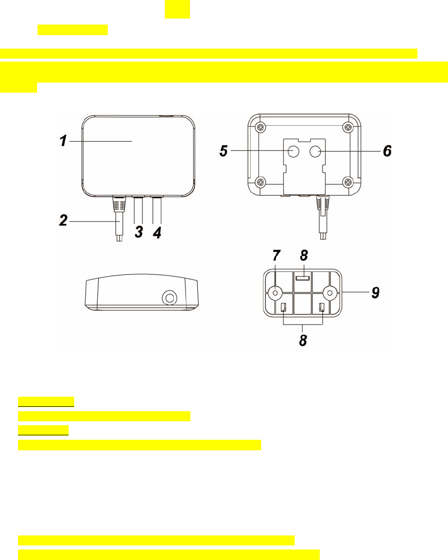
Parts Identification
1. Red LED
Flashes once:
When Clamp Meter is transmitting a signal.
Flash Twice:
The Clamp Meter has successfully joined a Z-Wave network.
2. AC Input cable
3. Current Transformer Cable (CT1)
4. Current Transformer Cable (CT2)
5. Function Button
-Press the button once to report the value of the meter to the Z-Wave network.
-Press the button 3 times within 1.5 seconds to transmit a learn code.
-Press and hold the button for 10 seconds to factory reset the Clamp Meter.
6. Reserved
7. Mounting Hole
8. Mounting Hooks
9. Mounting Bracket
Installation
Wiring
WARNING
Wiring of the device should only be performed by a licensed electrician. The circuit box’s main breaker
should be turned off to perform installation.
The insertion hole wire specification is AWG18 or Ø 1.02 (mm²).
The Clamp specification is 60A Ø10mm
Please make sure the main power in your facility is also off before installing. Follow the steps below:
1. Connect AC Input cable to a socket near the Electrical Box to power on the Clamp Meter.
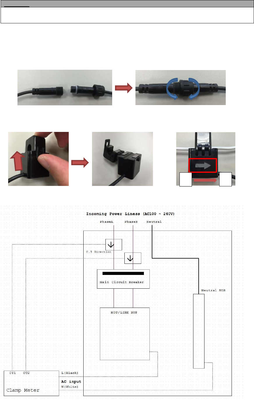
2. Attach both ends of the Current Transformer Cables first as picture shown below. Once you have attached
the Current Transformer Cable, start spinning the waterproof latch clock-wise until you have tighten and
secure both ends of the Current Transformer Cable.
3. Open the clamp as indicated by below picture. The clamp should be applied onto an electic cable The
arrow direction on the clamp need to point at the correct direction of the electricity current flows (KL). If
arrow is faced in reverse direction, the reading will display negative value (-) however it will not influence
the readings.
4. Follow the schematics below as an example; clip the clamps on the electricity cables on the 2 the
incoming power cable connected to the Main Circuit Breaker.
Mounting
The Clamp Meter has a mounting bracket for mounting purposes.
1. Use the mounting bracket as template to mark the two holes on the wall for installing screws.
KL
2. Screw the mounting bracket onto the wall according to marked location. Install wall plugs if necessary.
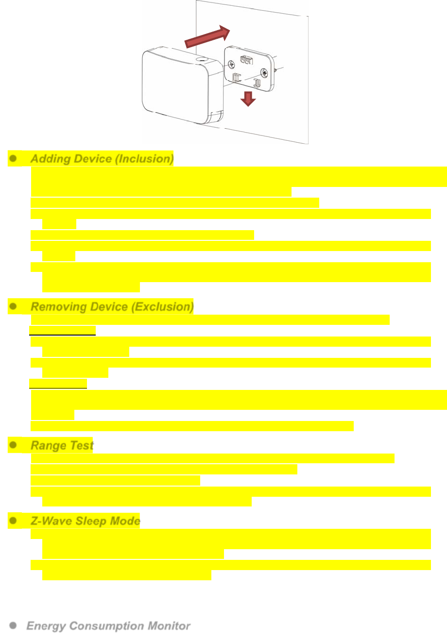
3. Locate the hooks of the mounting bracket and line up the hooks with the mounting holes on the Clamp
Meter. Fit the hooks into the mounting holes as picture below. Installation is now complete.
Adding Device (Inclusion)
This product can be included and operated in any Z-Wave network with other Z-Wave certified devices from
other manufactures and/or other applications. All non-battery operated nodes within the network will act as
repeaters regardless of vendor to increase reliability of the network.
Plug in the AC Input cable into the socket to power on the Clamp Meter.
Put the Z-Wave control panel into Inclusion mode (please refer to the Z-Wave control panel
manual).
Within 1.5 seconds, press the Function Button 3 times.
Refer to the operation manual of the Z-Wave Gateway or Control Panel to complete the adding
process.
If the device has already been added (included) into another Z-Wave Gateway/Control Panel, or if the
device is unable to be added into the current Z-Wave Gateway/Control Panel, try removing it first
(see Removing Device).
Removing Device (Exclusion)
The device must be removed from existing Z-Wave network before being added into another.
Exclusion Mode
Put the Z-Wave Gateway or Control Panel into Exclusion mode (please refer to the Z-Wave or
control panel manual).
Within 1.5 seconds, press the Function Button 3 times and the device will be removed from the
Z-Wave network.
Factory Reset
Factory resetting the device will restore it to factory default settings (i.e. not included into any Z-Wave
network). Please only use this procedure if the Z-Wave Gateway or Control Panel is lost or otherwise
inoperable.
Press and hold the Function Button of the device for 10 seconds to factory reset.
Range Test
To test whether the device is able to communicate with the Z-Wave Gateway or Control Panel:
Put the Gateway / Control Panel into range test mode (Walk Test).
Press the Function Button on the device.
The Gateway / Control Panel should display if the device is within the operation range (please refer to
the operation manual of the Gateway / Control Panel).
Z-Wave Sleep Mode
The Clamp Meter will enter Z-Wave Sleep mode (to conserve power) after waking up for a short
period of time (~10 seconds). While in Z-Wave sleep mode, Z-Wave Gateways or Control Panels are
unable to send commands to the Clamp Meter.
To program the Clamp Meter using the Z-Wave Gateway/Control Panel, please send command(s) to
the Clamp Meter within the wake-up period.
Energy Consumption Monitor
The Clamp Meter will transmit a signal from the clamp itself with its power consumption data every 10
minutes to the Z-Wave network coordinator.
Reading from clamp on Current Transformer Cable CT-1 is reported to Meter Channel 1
Reading from clamp on Current Transformer Cable CT-2 is reported to Meter Channel 2.
Whenever the Clamp’s energy output changes by +/- 2W, the Clamp Meter will automatically transmit
a signal with power consumption data to the Z-Wave network coordinator for update.
The Clamp Meter transmits a signal with power data to coordinator whenever accumulated power
usage of the clamp increases by 0.1kW/hr.
The Clamp has an accuracy of +/- 5%.
To clear the clamp of its accumulated power consumption data, follow steps below:
1. Un-plug AC cable to power down Clamp Meter.
2. Press and hold the function button, while holding the button, power on the Clamp Meter by
re-plug in the AC cable.
3. Release the function button when red LED starts to quickly flash.
4. Un-plug and re-plug AC cable again, clearing is complete.
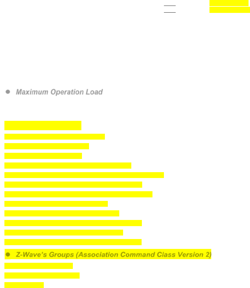
Maximum Operation Load
110V: 6600W and 60A
230V: 13800W and 60A.
Z-Wave Information
Device Type: Whole Home Meter - Simple
Role Type: Always On Slave (AOS)
Command Class Support/Control
Mandatory CC Support: Association CC, v2
Association Group Information CC
Device Reset Locally CC
Manufacturer Specific CC, v2
Meter CC,
Version CC, v2
Z-Wave Plus Info CC, v2
Power Level CC,
Firmware Update CC, v2
Z-Wave’s Groups (Association Command Class Version 2)
Group 1 for “LifeLine”:
Device Reset Locally CC
Meter CC
Federal Communication Commission Interference Statement
ThisequipmenthasbeentestedandfoundtocomplywiththelimitsforaClassBdigital
device,pursuanttoPart15oftheFCCRules.Theselimitsaredesignedtoprovide
reasonableprotectionagainstharmfulinterferenceinaresidentialinstallation.
Thisequipmentgenerates,usesandcanradiateradiofrequencyenergyand,ifnotinstalled
andusedinaccordancewiththeinstructions,maycauseharmfulinterferencetoradio
communications.However,thereisnoguaranteethatinterferencewillnotoccurina
particularinstallation.Ifthisequipmentdoescauseharmfulinterferencetoradioor
televisionreception,whichcanbedeterminedbyturningtheequipmentoffandon,the
userisencouragedtotrytocorrecttheinterferencebyoneofthefollowingmeasures:
.Reorientorrelocatethereceivingantenna.
.Increasetheseparationbetweentheequipmentandreceiver.
.Connecttheequipmentintoanoutletonacircuitdifferentfromthattowhichthereceiver
isconnected.
.Consultthedealeroranexperiencedradio/TVtechnicianforhelp.
FCCCaution:Toassurecontinuedcompliance,anychangesormodificationsnotexpressly
approvedbythepartyresponsibleforcompliancecouldvoidtheuser'sauthoritytooperate
thisequipment.(Example‐useonlyshieldedinterfacecableswhenconnectingtocomputer
orperipheraldevices).
ThisdevicecomplieswithPart15oftheFCCRules.Operationissubjecttothefollowingtwo
conditions:
(1)Thisdevicemaynotcauseharmfulinterference,and
(2)Thisdevicemustacceptanyinterferencereceived,includinginterferencethatmaycause
undesiredoperation.