Climax Technology Co COZB Carbon Monoxide Detector User Manual CO 8ZBS 20160511 FCC
Climax Technology Co Ltd Carbon Monoxide Detector CO 8ZBS 20160511 FCC
UserManual.wiki
>
Climax Technology Co
>
COZB User Manual
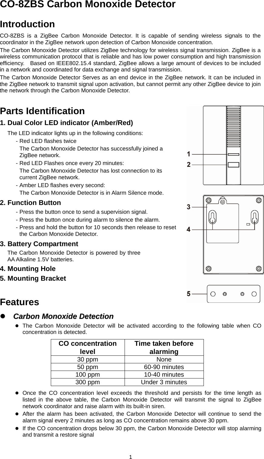
Users Manual
Navigation menu
Upload a User Manual
Namespaces
Wiki Guide
HTML
PDF
Info
Views
User Manual
Discussion / Help
Navigation