Climax Technology Co COZB Carbon Monoxide Detector User Manual CO 8ZBS 20160511 FCC
Climax Technology Co Ltd Carbon Monoxide Detector CO 8ZBS 20160511 FCC
Users Manual
1
CO-8ZBS Carbon Monoxide Detector
Introduction
CO-8ZBS is a ZigBee Carbon Monoxide Detector. It is capable of sending wireless signals to the
coordinator in the ZigBee network upon detection of Carbon Monoxide concentration.
The Carbon Monoxide Detector utilizes ZigBee technology for wireless signal transmission. ZigBee is a
wireless communication protocol that is reliable and has low power consumption and high transmission
efficiency. Based on IEEE802.15.4 standard, ZigBee allows a large amount of devices to be included
in a network and coordinated for data exchange and signal transmission.
The Carbon Monoxide Detector Serves as an end device in the ZigBee network. It can be included in
the ZigBee network to transmit signal upon activation, but cannot permit any other ZigBee device to join
the network through the Carbon Monoxide Detector.
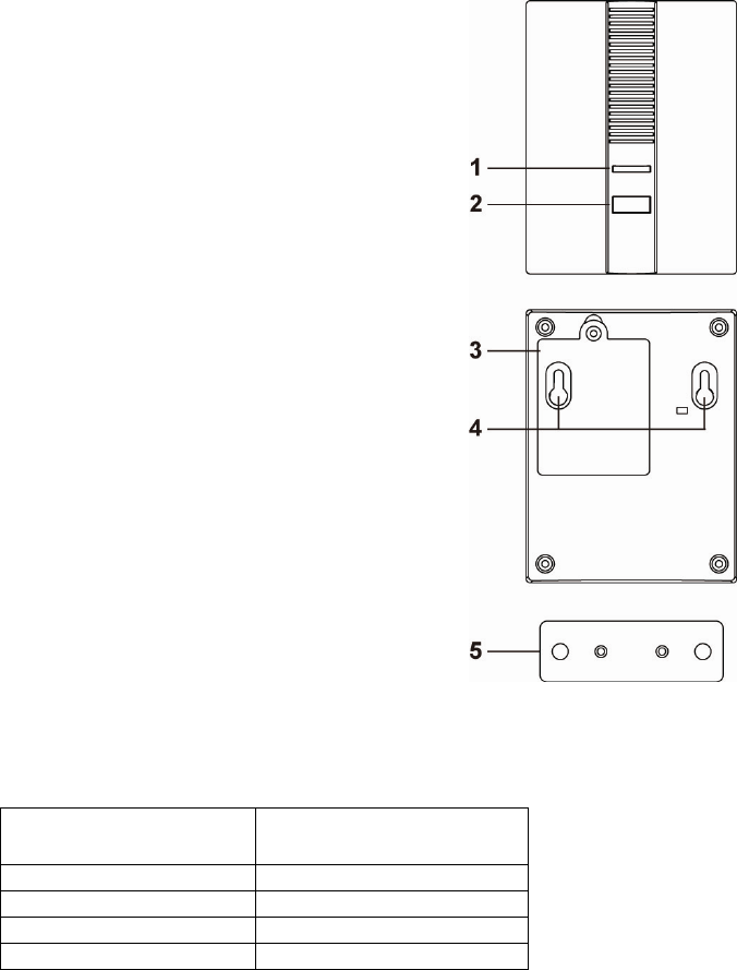
Parts Identification
1. Dual Color LED indicator (Amber/Red)
The LED indicator lights up in the following conditions:
- Red LED flashes twice
The Carbon Monoxide Detector has successfully joined a
ZigBee network.
- Red LED Flashes once every 20 minutes:
The Carbon Monoxide Detector has lost connection to its
current ZigBee network.
- Amber LED flashes every second:
The Carbon Monoxide Detector is in Alarm Silence mode.
2. Function Button
- Press the button once to send a supervision signal.
- Press the button once during alarm to silence the alarm.
- Press and hold the button for 10 seconds then release to reset
the Carbon Monoxide Detector.
3. Battery Compartment
The Carbon Monoxide Detector is powered by three
AA Alkaline 1.5V batteries.
4. Mounting Hole
5. Mounting Bracket
Features
C
Ca
ar
rb
bo
on
n
M
Mo
on
no
ox
xi
id
de
e
D
De
et
te
ec
ct
ti
io
on
n
The Carbon Monoxide Detector will be activated according to the following table when CO
concentration is detected.
CO concentration
level Time taken before
alarming
30 ppm None
50 ppm 60-90 minutes
100 ppm 10-40 minutes
300 ppm Under 3 minutes
Once the CO concentration level exceeds the threshold and persists for the time length as
listed in the above table, the Carbon Monoxide Detector will transmit the signal to ZigBee
network coordinator and raise alarm with its built-in siren.
After the alarm has been activated, the Carbon Monoxide Detector will continue to send the
alarm signal every 2 minutes as long as CO concentration remains above 30 ppm.
If the CO concentration drops below 30 ppm, the Carbon Monoxide Detector will stop alarming
and transmit a restore signal

2
A
Al
la
ar
rm
m
S
Si
il
le
en
nc
ce
e
When the Carbon Monoxide Detector is alarming, you can press the Function button once on
Carbon Monoxide Detector to enter Alarm Silence mode for 10 minutes
Under Alarm Silence mode, the Carbon Monoxide Detector will not sound alarm; the Amber
LED Indicator will flash every second to indicate it is under Alarm Silence mode.
After 10 minutes, if CO concentration still exceeds 30ppm, the Carbon Monoxide Detector will
raise alarm and send alarm signal again.
B
Ba
at
tt
te
er
ry
y
a
an
nd
d
L
Lo
ow
w
B
Ba
at
tt
te
er
ry
y
D
De
et
te
ec
ct
ti
io
on
n
The Carbon Monoxide Detector uses three 1.5V Alkaline batteries as its power source. The
batteries are included in the package.
The Carbon Monoxide Detector feature Low Battery Detection function. When low battery
voltage is detected, the Carbon Monoxide Detector will transmit Low Battery signal to notify the
user.
When changing batteries, after removing the old batteries, press the Function Button twice to
fully discharge before inserting new batteries.
S
Su
up
pe
er
rv
vi
is
si
io
on
n
The Carbon Monoxide Detector will transmit a supervision signal to report its condition regularly
according to user setting. The factory default interval is 30 minutes. The user can also press the
Function Button once to transmit a supervision signal manually.
ZigBee Network Setup
Z
Zi
ig
gB
Be
ee
e
D
De
ev
vi
ic
ce
e
G
Gu
ui
id
de
el
li
in
ne
e
ZigBee is a wireless communication protocol that is reliable and has low power consumption and
high transmission efficiency. Based on IEEE802.15.4 standard, ZigBee allows a large amount of
devices to be included in a network and coordinated for data exchange and signal transmission.
Due to the fundamental structure of ZigBee network, ZigBee device will actively seek and join
network after powering on. Since performing a task in connecting network may consume some
power, it is required to follow the instructions to avoid draining battery of a ZigBee device
- Ensure your ZigBee network router or coordinator is powered on before inserting battery into the
ZigBee device.
- Ensure the ZigBee network router or coordinator is powered on and within range while a ZigBee
device is in use.
- Do not remove a ZigBee device from the ZigBee network router or coordinator without removing
the battery from a ZigBee device.
J
Jo
oi
in
ni
in
ng
g
t
th
he
e
Z
Zi
ig
gB
Be
ee
e
N
Ne
et
tw
wo
or
rk
k
As a ZigBee device, the Carbon Monoxide Detector needs to join a ZigBee network to transmit
signal when smoke concentration is detected. Please follow the steps bellow to join the Carbon
Monoxide Detector into the ZigBee network.
1. Insert the batteries into the battery compartment to power on the Carbon Monoxide Detector.
2. The Carbon Monoxide Detector will emit two short beeps when it is powered on.
3. Press and hold the function button for 10 seconds then release to join ZigBee network. Please
make sure to enable the permit-join feature on the router or coordinator of your ZigBee network
4. After joining the ZigBee network, the Carbon Monoxide Detector will be registered in the network
automatically. Please check the ZigBee network coordinator, system control panel or CIE
(Control and Indicating Equipment) to confirm if joining and registration is successful. If the
Carbon Monoxide Detector successfully joins the ZigBee network, the Red LED will flash twice to
confirm.
5. After joining the ZigBee network, if the Carbon Monoxide Detector loses connection with its
current ZigBee network, the Red LED will flash every 20 minutes to indicate. Please check your
ZigBee network condition and Carbon Monoxide Detector signal range to correct the situation.
R
Re
em
mo
ov
vi
in
ng
g
D
De
ev
vi
ic
ce
e
f
fr
ro
om
m
Z
Zi
ig
gB
Be
ee
e
N
Ne
et
tw
wo
or
rk
k
(
(F
Fa
ac
ct
to
or
ry
y
R
Re
es
se
et
t)
)
To remove the Carbon Monoxide Detector from current ZigBee network, the device must be put to
Factory Reset to complete device removal. Factory Reset function will clear the Carbon Monoxide
Detector of its stored setting information and prompt the device to search for new ZigBee network.
Before removing device, make sure the Carbon Monoxide Detector is within current ZigBee
network signal range
1. Press and hold the function button for 10 seconds, then release the button to reset Carbon
Monoxide Detector.

3
2. Upon reset, the device will clear current ZigBee network setting and transmit signal to ZigBee
coordinator to remove itself from current ZigBee network. It will then actively search for
available ZigBee network again and join the network automatically.
Installation
I
In
ns
st
ta
al
ll
la
at
ti
io
on
n
G
Gu
ui
id
de
el
li
in
ne
e
It is recommended to install the Carbon Monoxide Detector in following locations.
Install the Carbon Monoxide Detector in your bedrooms to protect your safety.
For houses with garage, also mount near the internal door to garage and the room above the
garage for protection in case when car engin is not turned off.
Avoid mounting in following locations.
Inside kitchen and garage – to avoid false alarm when
Corner or location with stagnant air – to avoid false alarm
Fireplace – Keep at least 4.5 meters of distance to avoid false alarm.
I
In
ns
st
ta
al
ll
la
at
ti
io
on
n
A mounting bracket is provide in the package for mounting the Carbon Monoxide Detector on the
wall.
1. Refer to Control Panel manual and put the Control Panel into Walk Test mode.
2. Put the Carbon Monoxide Detector at desired installation location, press the Learn/Test button to
transmit signal to panel.
3. If the panel receives signal, it will display the device signal strength. Check and make sure the
panel can receive signal normally from device at current location. If signal reception is
unsatisfactory, relocate the Carbon Monoxide Detector and repeat Step 1~3 until an ideal
installation location is found.
4. Use the mounting bracket as template to mark the two holes on the wall at chosen location for
installing screws.
5. Screw the mounting bracket onto the wall according to marked location. Install wall plugs if
necessary.
6. Hook the Carbon Monoxide Detector onto the mounting bracket. Installation is now complete.
U
Us
si
in
ng
g
C
Ca
ar
rb
bo
on
n
M
Mo
on
no
ox
xi
id
de
e
D
De
et
te
ec
ct
to
or
r
w
wi
it
th
h
Z
Zi
ig
gB
Be
ee
e
R
Ro
ou
ut
te
er
r
IMPORTANT NOTE
If the Carbon Monoxide Detector installation location is away from your system control panel and
requires ZigBee routers to improve signal strength. DO NOT use a ZigBee Router without backup
battery. A ZigBee router without battery will be powered down during AC power failure and the
Carbon Monoxide Detector connected to the router will lose connection with ZigBee network. You
should plan your Carbon Monoxide Detector installation location using only ZigBee router with
backup battery.
Appendix (For developers only.)
C
Ca
ar
rb
bo
on
n
M
Mo
on
no
ox
xi
id
de
e
D
De
et
te
ec
ct
to
or
r
C
Cl
lu
us
st
te
er
r
I
ID
D
Device ID: IAS Zone 0x402
Endpoint: 0x01
Server Side Client Side
Mandatory
Basic (0x0000) None
Identify(0x0003)
IAS Zone(0x0500)
Optional
None None
A
At
tt
tr
ri
ib
bu
ut
te
e
o
of
f
B
Ba
as
si
ic
c
C
Cl
lu
us
st
te
er
r
I
In
nf
fo
or
rm
ma
at
ti
io
on
n
Identifier Name Type Range Access Default
Mandatory
/ Optional
0x0000 ZCLVersion Unsigned
8-bit integer 0x00 –0xff Read only 0x01 M
0x0003 HWVersion Unsigned
8-bit integer 0x00 –0xff Read only 0 O

4
0x0004 ManufacturerName Character
String 0 – 32 bytes Read only Climax
Technology O
0x0005 ModelIdentifier Character
String 0 – 32 bytes Read only (Model
Version) O
0x0006 DateCode Character
String 0 – 16 bytes Read only O
0x0007 PowerSource 8-bit 0x00 –0xff Read only M
0x0010 LocationDescription Character
String 0 – 32 bytes Read /
Write O
0x0011 PhysicalEnvironment 8-bit 0x00 –0xff
Read /
Write 0x00 O
0x0012 DeviceEnabled Boolean 0x00 –0x01 Read /
Write 0x01 M
A
At
tt
tr
ri
ib
bu
ut
te
e
o
of
f
I
Id
de
en
nt
ti
if
fy
y
C
Cl
lu
us
st
te
er
r
I
In
nf
fo
or
rm
ma
at
ti
io
on
n
Identifier Name Type Range Access Default
Mandatory
/ Optional
0x0000 IdentifyTime Unsigned
16-bit integer 0x00 –0xffff Read /
Write 0x0000 M
A
At
tt
tr
ri
ib
bu
ut
te
e
o
of
f
I
IA
AS
S
Z
Zo
on
ne
e
C
Cl
lu
us
st
te
er
r
I
In
nf
fo
or
rm
ma
at
ti
io
on
n
Identifier Name Type Range Access Default
Mandatory
/ Optional
0x0001 ZoneState 8-bit
Enumeration All Read
only 0x00 M
0x0002 ZoneType 8-bit
Enumeration All Read
only M
0x0003 ZoneStatus 16-bit bitmap All Read
only 0x00 M
0x0010 IAS_CIE_ADDRESS IEEE
ADDRESS Valid 64bit
IEEE address Read /
Write M
0x0011 ZONE_ID Unsigned 8-bit
integer All Read
only 0xFF M
5
Federal Communication Commission Interference Statement
This equipment has been tested and found to comply with the limits
for a Class B digital device, pursuant to Part 15 of the FCC Rules.
These limits are designed to provide reasonable protection against
harmful interference in a residential installation.
This equipment generates, uses and can radiate radio frequency
energy and, if not installed and used in accordance with the
instructions, may cause harmful interference to radio communications.
However, there is no guarantee that interference will not occur in a
particular installation. If this equipment does cause harmful
interference to radio or television reception, which can be determined
by turning the equipment off and on, the user is encouraged to try to
correct the interference by one of the following measures:
. Reorient or relocate the receiving antenna.
. Increase the separation between the equipment and receiver.
. Connect the equipment into an outlet on a circuit different from that
to which the receiver is connected.
. Consult the dealer or an experienced radio/TV technician for help.
FCC Caution
: To assure continued compliance, any changes or
modifications not expressly approved by the party responsible for
compliance could void the user's authority to operate this equipment.
(Example - use only shielded interface cables when connecting to
computer or peripheral devices).
FCC Radiation Exposure Statement
This equipment complies with FCC RF radiation exposure limits set
forth for an uncontrolled environment. This equipment should be
installed and operated with a minimum distance of 20 centimeters
between the radiator and your body.
This transmitter must not be co-located or operating in conjunction
with any other antenna or transmitter.
The antennas used for this transmitter must be installed to provide a
separation distance of at least 20 cm from all persons and must not
be co-located or operating in conjunction with any other antenna or
transmitter.
This device complies with Part 15 of the FCC Rules. Operation is
subject to the following two conditions:
(1) This device may not cause harmful interference, and
(2) This device must accept any interference received, including
interference that may cause undesired operation.