Climax Technology Co CTC1052LTE Wirless Medical Alarm User Manual
Climax Technology Co Ltd Wirless Medical Alarm Users Manual
UserManual.wiki
>
Climax Technology Co
>
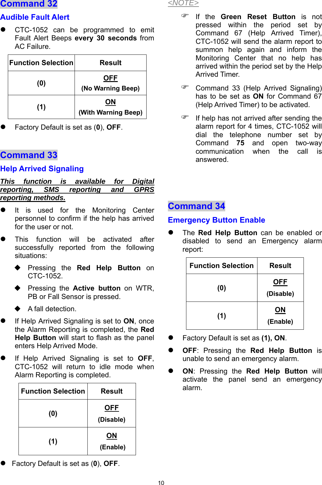
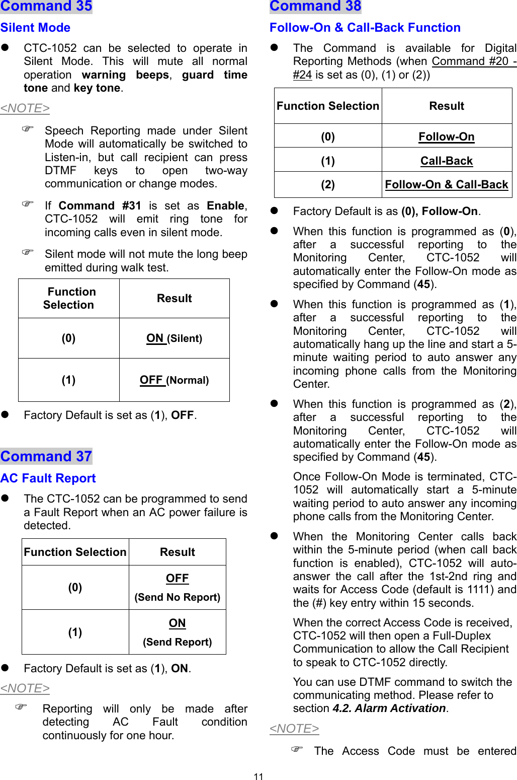
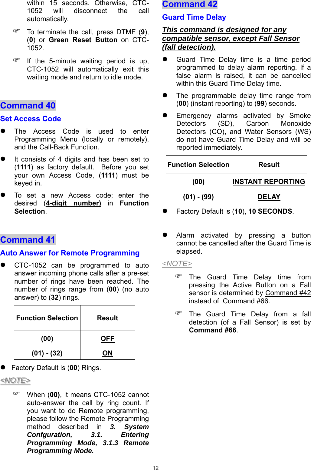
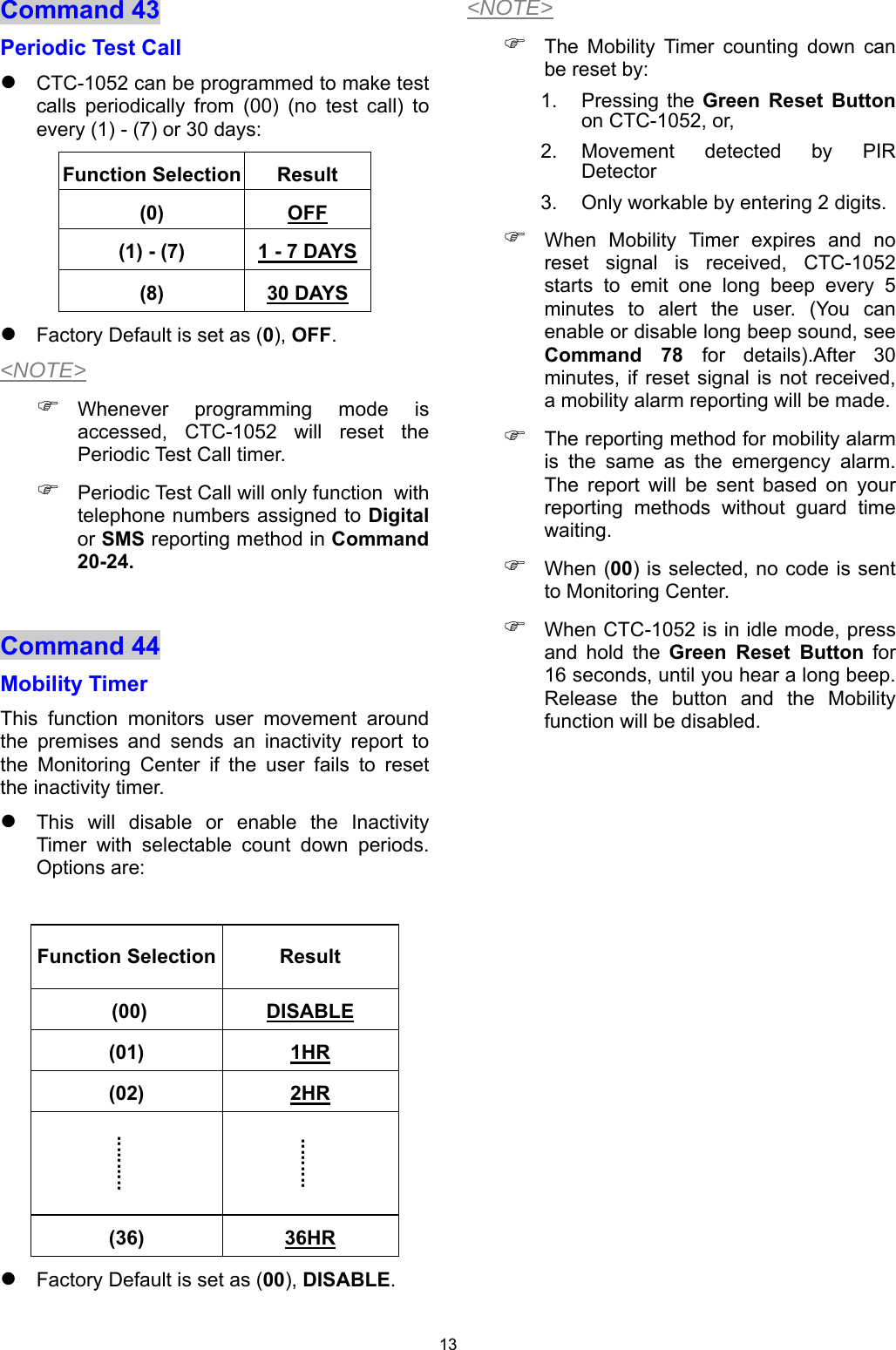
CTC1052LTE User Manual
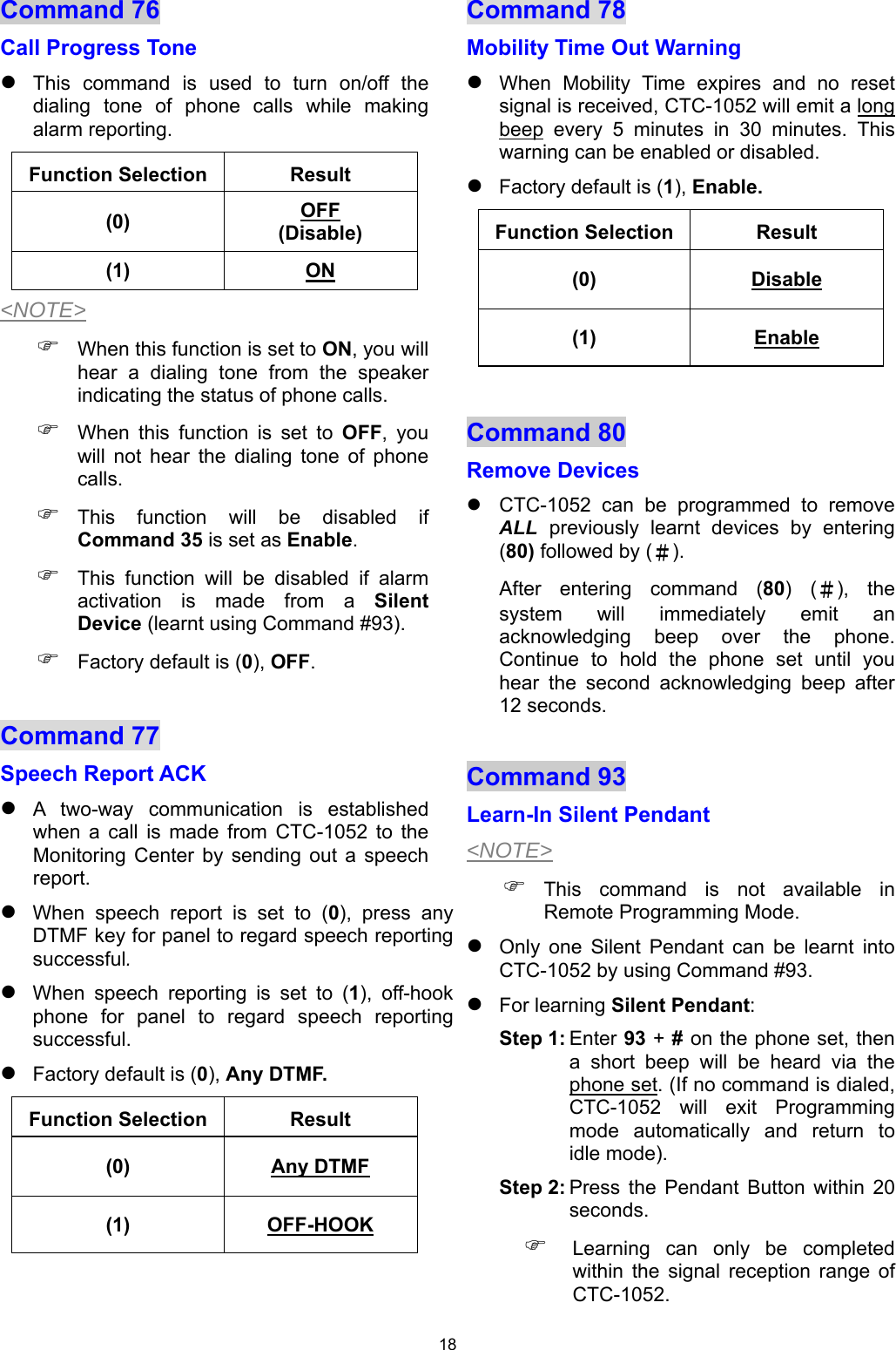
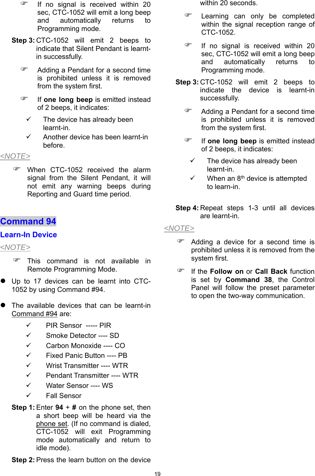
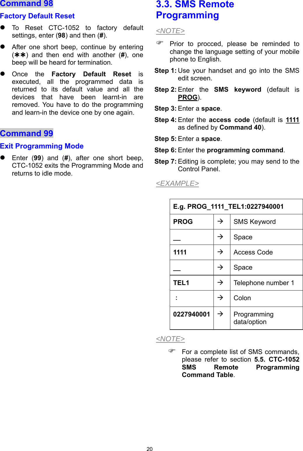
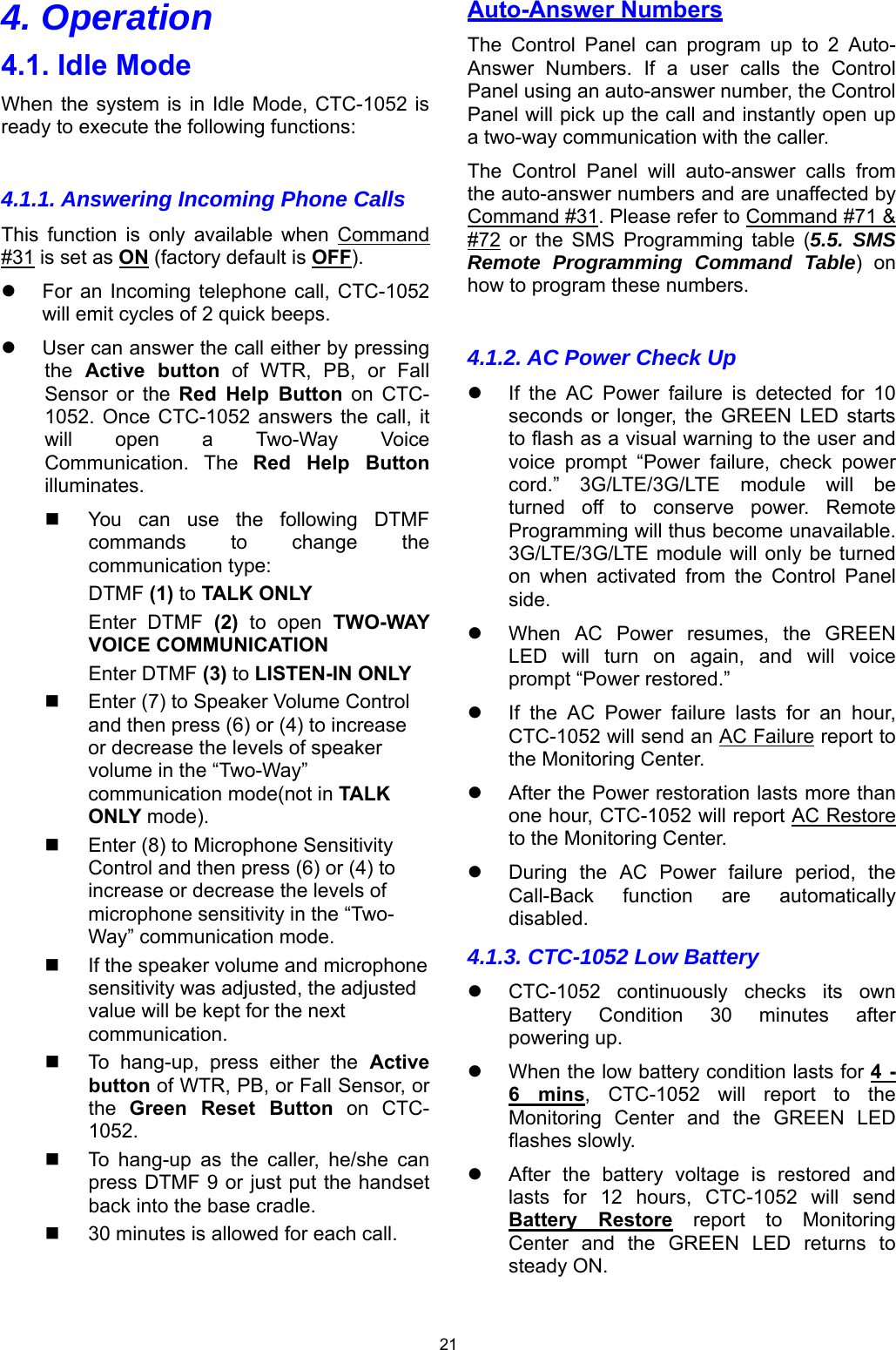
Users Manual
Navigation menu
Upload a User Manual
Namespaces
Wiki Guide
HTML
PDF
Info
Views
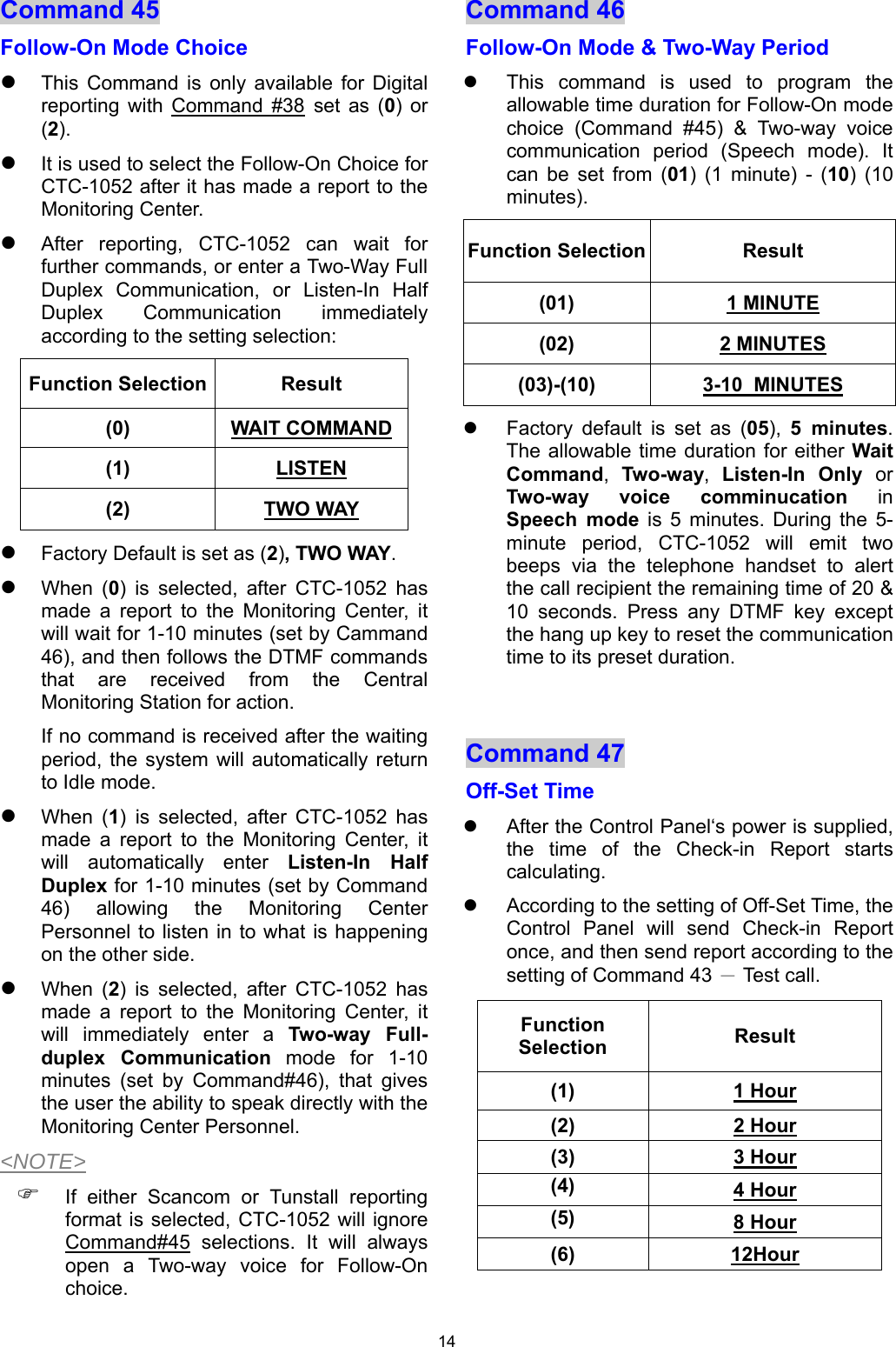
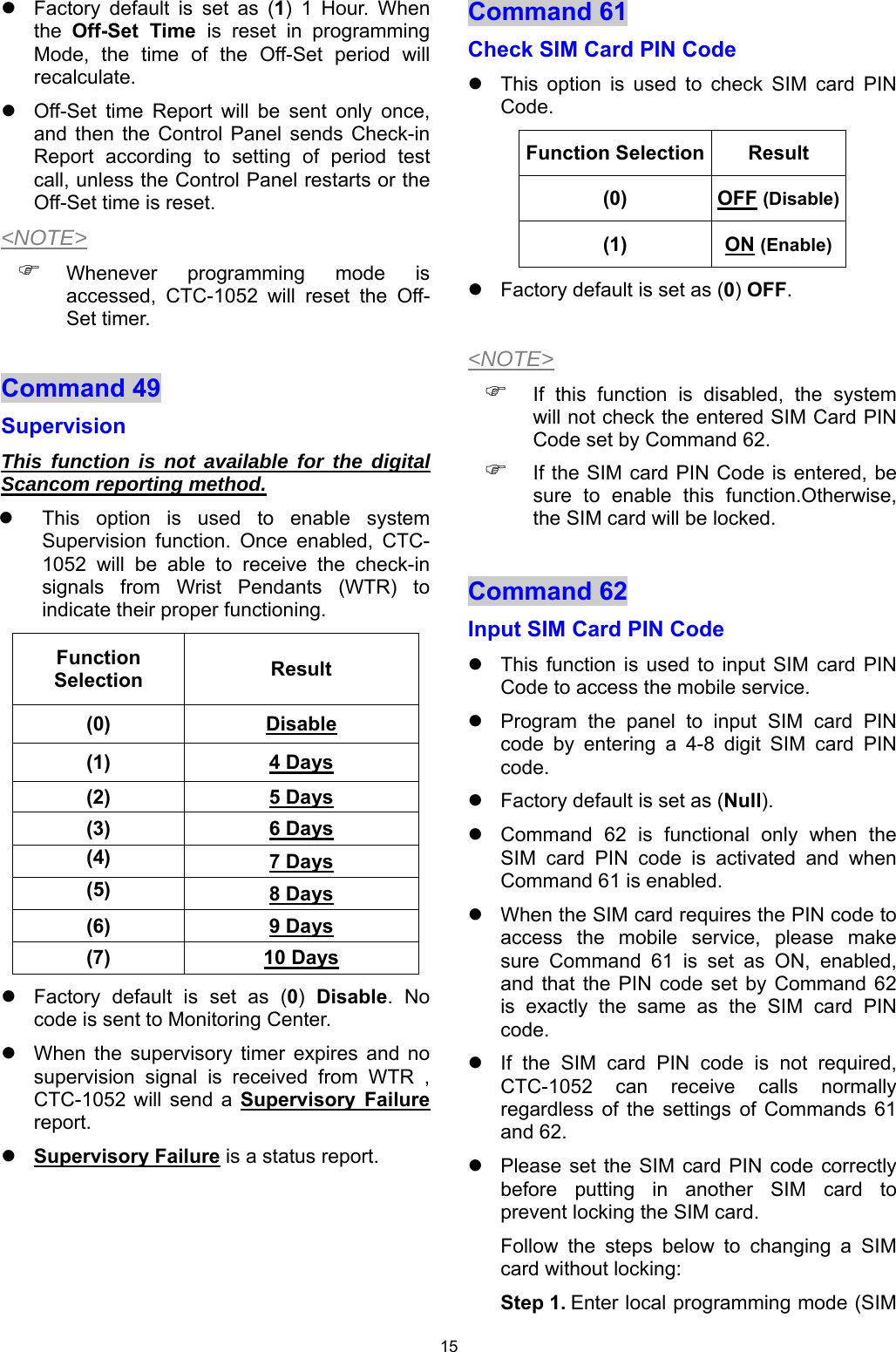
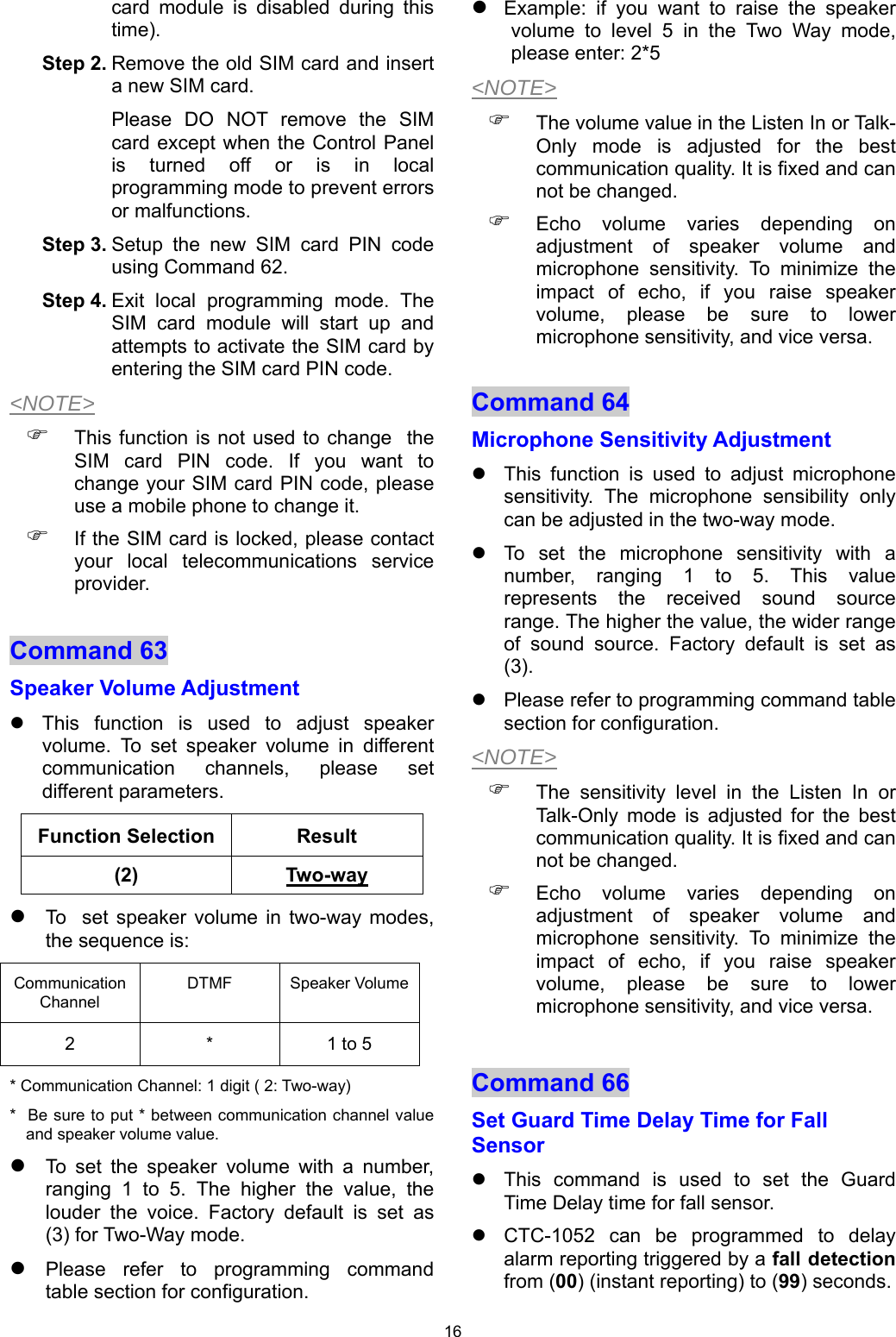
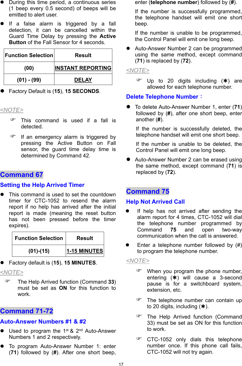
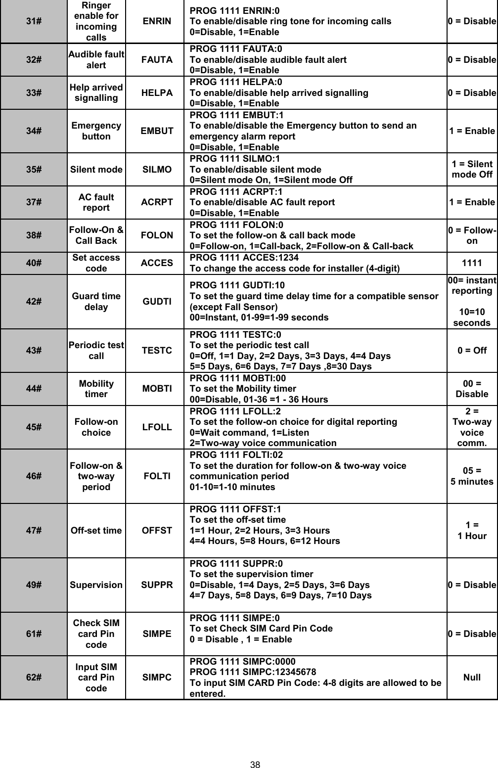
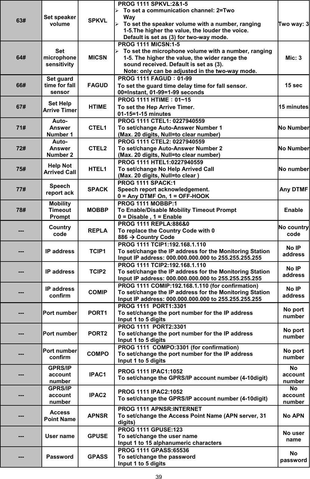
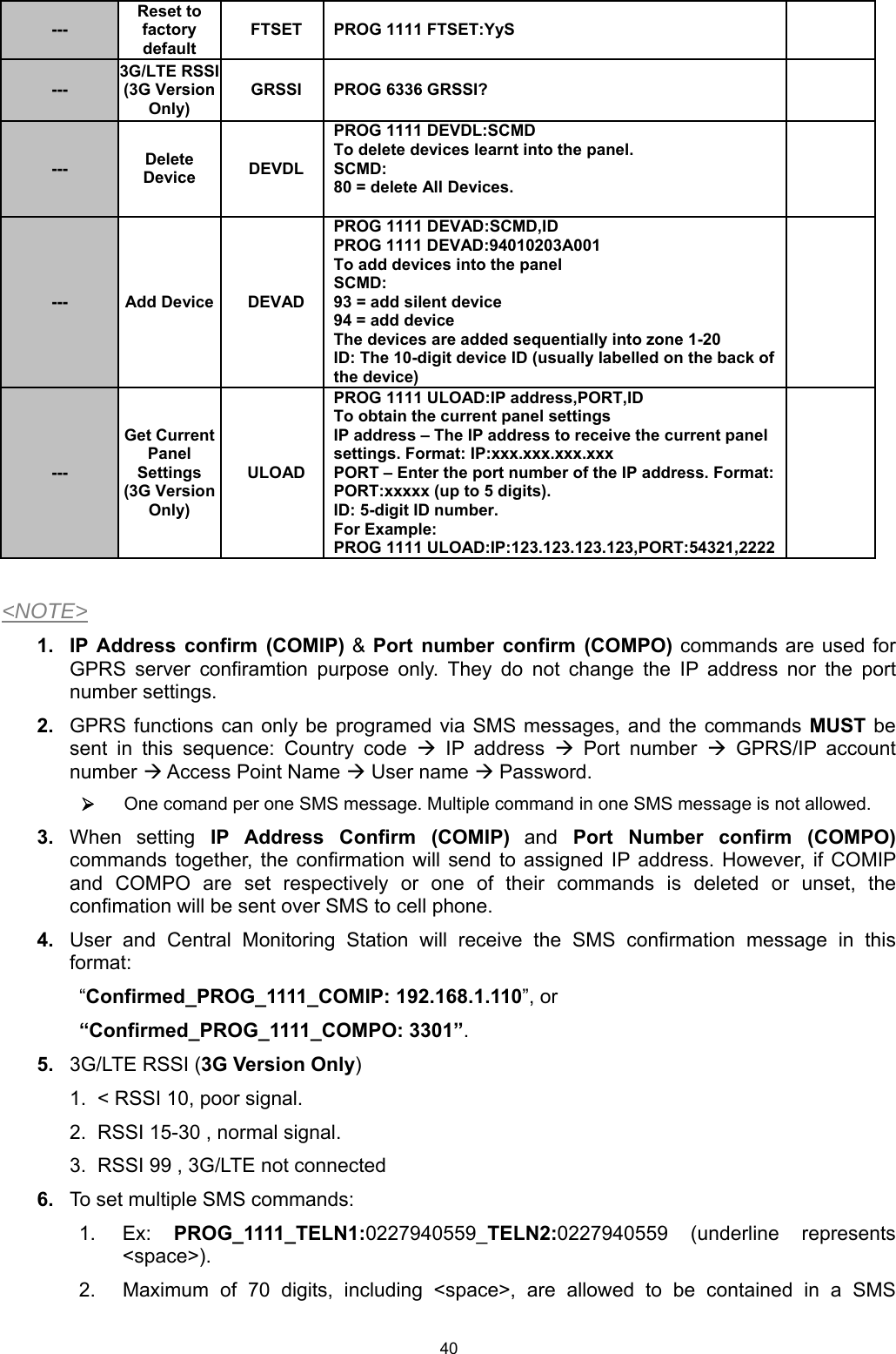
User Manual
Discussion / Help
Navigation