Climax Technology Co CTC1052LTE Wirless Medical Alarm User Manual
Climax Technology Co Ltd Wirless Medical Alarm Users Manual
Users Manual

+--E1
August 25, 2017

Table of Contents
1. Application Overview ____________________________________________________ 1
1.1. Identifying The Parts _________________________________________________ 1
1.2. The Power Supply ___________________________________________________ 2
1.3. Insert GPRS/3G/LTE SIM Card _________________________________________ 2
1.4. How to install the Control Panel ________________________________________ 3
1.5. Compatible with Climax’s SMS Editor ___________________________________ 3
2. Learn-in the Devices ____________________________________________________ 4
2.1. Command Learning __________________________________________________ 4
2.2. Local Learning ______________________________________________________ 4
2.3. Learn-In Device using Device ID ________________________________________ 4
3. System Configuration ___________________________________________________ 5
3.1. Entering Programming Mode __________________________________________ 5
3.1.1. Local Programming Mode __________________________________________________________ 5
3.1.2. CTC-835 Programmer ____________________________________________________________ 5
3.1.3. Remote Programming Mode ________________________________________________________ 5
3.1.4. SMS Remote Programming __________________________________________ 6
3.2. Programming Your 1052 ______________________________________________ 6
3.3. SMS Remote Programming ___________________________________________ 20
4. Operation ____________________________________________________________ 21
4.1. Idle Mode __________________________________________________________ 21
4.1.1. Answering Incoming Phone Calls ___________________________________________________ 21
4.1.2. AC Power Check Up _____________________________________________________________ 21
4.1.3. CTC-1052 Low Battery ___________________________________________________________ 21
4.1.4. CTC-1052 Battery Disconnection ___________________________________________________ 22
4.1.5. Devices Low Battery _____________________________________________________________ 22
4.1.6. Automatic Check-in Report = Periodic Test Call ________________________________________ 22
4.1.7. Mobility Timer __________________________________________________________________ 22
4.1.8. Country Code __________________________________________________________________ 23
4.2. Alarm Activation ____________________________________________________ 24
4.2.1. GPRS Reporting Method _______________________________________________________________ 24
4.2.2. Digital Reporting Method _______________________________________________________________ 25
4.2.3. Help Arrived Mode _____________________________________________________________________ 27
4.2.4. Speech Reporting Method ______________________________________________________________ 28
4.2.5. Report Sequence ______________________________________________________________________ 28
4.3 Walk Test (Range Test) _______________________________________________ 29
4.3.1. In Learning Mode _______________________________________________________________ 29
4.3.2. In Walk Test Mode ______________________________________________________________ 29
4.3.3. In Idle Mode ___________________________________________________________________ 30
4.4 Global Test _________________________________________________________ 30
4.5 Factory Reset _______________________________________________________ 30
5. Appendix _____________________________________________________________ 31
5.1. CID Event Code __________________________________________________________________ 31
5.2. Tunstall Event Code_______________________________________________________________ 32
5.3. Scancom Event Code _____________________________________________________________ 33
5.4. CTC-1052 Programming Command Table _____________________________________________ 35
5.5. CTC-1052 SMS Remote Programming Command Table __________________________________ 37
1
1. Application Overview
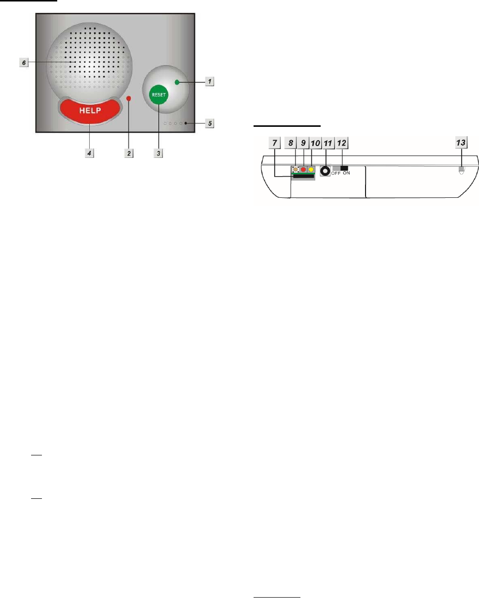
1.1. Identifying The Parts
TOP VIEW
1. GREEN LED
— ON: AC Power is ON.
— FLASH every second: AC Power
failure
— FLASH every 2 seconds: Panel or
Device Low battery
— QUICK FLASH every 2 seconds:
Supervision failure
2. RED LED
— ON: Off-hook / Waiting retry pause /
Ready to enter Programming Mode
(before entering PIN code)
— FLASH: Programming Mode /
Pendant Learning Mode
3. GREEN RESET BUTTON
— Press once in normal mode to reset
mobility timer (see command 44)
— Before CTC-1052 dials out for alarm
reporting, press once to cancel the
alarm reporting
— During or at-the-end of conversation,
press once to terminate two-way
voice communication
— Press & hold for 3 sec: dial the Non-
Emergency call. (See section 4.1.2.)
— Press & hold for 6 sec: enter Learning
Mode
— Press & hold for 16 sec: disable
mobility setting
4. RED HELP BUTTON (with backlight)
— Back-lit disigned for easy access at
night
— Backlight illuminates when off-hook
— Backlight flashes during the waiting
period until help arrives
5. Microphone
6. Speaker
REAR VIEW
7. GPRS/3G/LTE SIM Card Base
— This slot is for inserting a SIM card.
8. GPRS/3G/LTE Reset Button
— Press & hold for 1 sec: GPRS/3G/LTE
automatically resets
9. GPRS/3G/LTE Module LED Indicator
(Red)
— When power is supplied to CTC-1052,
the LED will light up for 5 seconds.
— One flash per second indicates
3G/LTE noraml connection.
— Continuous 5-second flashes indicate
there is no 3G/LTE connection/signal.
10. GPRS/3G/LTE Fault Indicator
(Yellow)
— FLASH every 5 seconds: SIM card
missing
— 2 FLASHES every 5 seconds: No
signal/reception
— 3 FLASHES every 5 seconds:
GPRS/3G/LTE module abnormal
— 4 FLASHES every 5 seconds: SIM
card PIN code error
<NOTE>
Fault indicator priorities: GPRS/3G/LTE
module abnormal > SIM card missing >
No signal/reception > SIM card PIN
2
code error
11. DC Jack
— DC 12V 1A switching power
connection
12. Battery Switch
13. Local Programming Telephone Unit
Input
— A special telephone cord to connect
CTC-1052 and your phone unit for
Local Programming (optional).
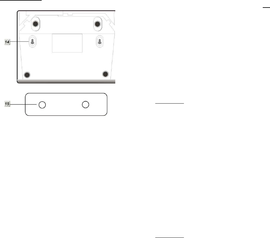
BACK VIEW
14. Mounting Holes
15. Mounting Bracket
1.2. The Power Supply
An AC power adapter is required to connect
to a wall outlet. Be sure only to use an
adapter with the appropriate AC voltage
rating to prevent component damage. A DC
12V output and 1A switching power is
generally used to power CTC-1052.
In addition to the adapter, there is a
rechargeable battery inside CTC-1052,
which serves as a back-up in case of a
power failure.
During normal operation, the AC power
adapter is used to supply power to CTC-
1052 and at the same time recharge the
battery. It takes approximately 72 hours to
fully charge the battery.
The battery can be manually disconnected
by the battery switch located at the bottom.
Battery Switch is set as OFF by factory
default, the battery will not be charged
when AC power is connected, nor will it
serve as a back-up power source when AC
power is missing. You need to switch the
battery to ON after supplying AC power to
CTC-1052
<NOTE>
Please make sure the battery switch is
slid back to ON position (as marked)
after manually disconnected the
rechargable battery.
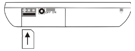
1.3. Insert GPRS/3G/LTE SIM
Card
CTC-1052 Panel features built-in GPRS/3G/LTE
communication facility to report to the
Monitoring Station.
To Insert SIM card:
<NOTE>
It is recommended to disable the SIM
card PIN code before inserting into the
Control Panel.
The GPRS/3G/LTE SIM card base is located on
the rear side of the unit:
3
Insert the SIM card with the chip side facing
up.
Push to the furthest extend, then press on
the edge of the SIM card firmly to secure it.
SIM Card will delete its SMS message
whenever the CTC-1052 is powered on.
To remove SIM card:
Press and release on the edge of SIM card, the
card will spring out.
1.4. How to install the Control
Panel
Locating a suitable position for the
Control Panel
The Control Panel requires main power and
a constant GPRS/3G/LTE reception.
The Control Panel should be easily
accessible.
The Control Panel should not be placed in
a damp location, such as a bathroom.
The Control Panel should not be placed
close to any heat source, such as
microwave ovens, which can reduce signal
strength.
The Control Panel should not be located
alongside other radio transmitting devices,
such as mobile phones, cordless phone, or
wireless computer network (Wi-Fi) devices.
Important: When drilling into a wall, ensure
there are no hidden cables or pipes.
Mounting the Control Panel
The Control Panel can be mounted on the wall
or wherever desired (e.g. on the table). Ensure
the Control Panel is fitted at approximately chest
height where the buttons, microphone, and
speaker can be easily accessed and operated.
Use the 2 holes of the Wall Mounting
Bracket as a template, mark off the holes’
positions.
Drill 2 holes and insert the wall plugs if
fixing into plaster or brick.
Screw the base to the wall.
Hook the Control unit onto the Wall
Mounting Bracket (holding the unit with the
front facing you).
1.5. Compatible with Climax’s
SMS Editor
CTC-1052 is compatible with Climax’s SMS
Editor, which is designed to facilitate SMS
remote programming via a PC. This tool allows
you to program the panel easily from your
computer, without sending complex SMS text
messages from a mobile phone.

4
2. Learn-in the Devices
There are two methods to learn in devices:
command learning and local learning. The
system can learn a total of 20 sensors.
2.1. Command Learning
Command Learning:
1. The user can use Commands 91-94 to
learn devices into the system.
2. Command 93 is designed to learn in
devices for silent reporting, including
WTR, Fall Sensor, or Panic Button.
3. Command 93 & 94 is designed to learn
in the following devices and sensors.
PIR Sensor ----- PIR
Smoke Detector ---- SD
Carbon Monoxide Detector---- CO
Fixed Panic Button ---- PB
Wrist Transmitter ---- WTR
Pendant Transmitter ---- WTR
Water Sensor ---- WS
Fall Sensor ---- FS
2.2. Local Learning
Local Learning:
The user can also use the local learning
method to learn in all devices.
1. When the device is learnt in for the first
time, voice prompt will prompt the
device/sensor name and “learned.”
2. Within 3 minutes after exiting learning
mode, the control panel will emit 1 long
beep everytime it receives a test code (from
any device).
3. Local Learning Mode cannot remove
devices or sensors.
To enter Local Learning Mode:
1. Press and hold the Green Reset Button of
the CTC-1052. When pressed, the CTC-
1052 will emit one beep sound initially, and
then will emit a double beep on the 6th
second.
2. Release the Green Reset Button at the
voice prompt “Release the Green button,
Ready to learn sensor.” CTC-1052 is now
in learning mode and the Red LED will start
flashing.
3. Press the (Learn) button on the device or
sensor. Voice Prompt: “(Name of Sensor)
learned.”
4. If no action within 10 seconds after “Ready
to learn sensor” prompt, CTC-1052 will
prompt “Press sensor button.” This prompt
will repeat two times if no action.
5. If no action after second “Press sensor
button” prompt, CTC-1052 will prompt
“Press Green button to exit learning mode.”
This prompt will be repeated three times if
no action continutes.
6. If no action after 5 minutes, the CTC-1052
will automatically exit Local Learning Mode
and return to idle mode. Voice Prompt: “We
are now in Normal Operation Mode.”
2.3. Learn-In Device using
Device ID
If sensor device ID is given (please consult
the supplier), the users can learn the device
into the Control Panel using device ID.
User can use SMS commands or the
programming tool SMS iWizard (sold
separately) to learn devices using device ID.
Please refer to the table CTC-1052 SMS
Programming Command Table or the SMS
iWizard operation manual on how to learn in
devices into different zones using device ID.

5
3. System Configuration
3.1. Entering Programming
Mode
Two CTC-1052 programming modes are
available: Local Programming Mode and
Remote Programming Mode.
<NOTE>
GPRS/3G/LTE module will be powered
down when in Programming Mode.
When AC Power resumes or when
exits from Programming Mode,
GPRS/3G/LTE module will be powered
on again.
3.1.1. Local Programming Mode
From Idle mode, follow the steps below to enter
Local Programming mode.
Step 1. Plug in the telephone set into LOCAL
PROGRAMMING input located on the
rear side of CTC-1052.
Step 2. Pick up the handset.
RED LED lights up.
Step 3. Enter default ACCESS CODE, 1111
followed by #.
Step 4. CTC-1052 will emit 2 short beeps and
the red LED starts to flash, indicating it
is in Programming Mode.
Step 5. Proceed to program system by
referring to the Commands in section
3.2 Programming Your 1052.
<NOTE>
Local programming is prohibited when
AC Power fails.
The first digit of Access Code must be
entered within 15 seconds, otherwise
CTC-1052 will exit automatically.
Failure to enter the correct Access
Code within 2 minutes will cause CTC-
1052 to exit the Programming mode
automatically.
To exit Programming mode, enter 99
followed by #, or place the handset on
hook, or disconnect the Programming
telephone set.
3.1.2. CTC-835 Programmer
CTC-835 is a powerful programming tool (sold
separetely) that features a built-in keypad and
LCD display to help you to program the medical
alarm panels effeciently and conveniently. It
also features Once-for-All Uploading, which
allows you program on a computer via the
supplied Pilot software and you can then upload
all the settings to the medical alarm panel
simultaneously with a single mouse click.
For detailed usages, please refer to the
Operation Manual of CTC-835 Programmer.
3.1.3. Remote Programming Mode
To allow Remote Programming, there are two
options for CTC-1052 to answer the incoming
calls.
(1) Auto Answering by ring count
(2) Dial in twice (Ring Count disable)
The two options are set by Command #41.
Please refer to Command 41 under section 3.2
Programming Your 1052.
3.1.3.1. Auto Answering by Ring Count
By using Command 41, you can set the number
of rings for CTC-1052 to answer (00-Rings is
set as factory default).
Step 1. Dial CTC-1052 and wait for CTC-1052
to answer.
Step 2. Enter 1111 (default 4-digit Access
Code) followed by #, via the phone set.
Step 3. CTC-1052 will respond with two quick
beeps to indicate it is ready for Remote
Programming. The RED LED will flash
as a visual indication.
Step 4. You are now in Programming Mode.
Proceed to program by referring to the
Command under section 3.2
Programming Your 1052.
3.1.3.2. Dial in Twice (Ring Count Disable)
As 00 is set in Command 41 by default, it means
CTC-1052 is disabled to auto answer the
incoming calls by ring count. If Remote
programming is required, you will need to call
CTC-1052 twice.

6
Step 1. Dial CTC-1052 and hang up after first 2
rings, wait for another 8-20 sec then
call again. CTC-1052 will answer the
call on the first ring. You will enter the
Remote Programming Mode after the
first ring from the 2nd call.
Step 2. Enter 1111 (the default 4-digit Access
Code) followed by #, via the phone set.
Step 3. CTC-1052 will respond with two quick
beeps to indicate it is ready for Remote
Programming Commands. The RED
LED will flash as a visual indication.
Step 4. You are now in Programming Mode.
Proceed to program by referring to the
Command in section 3.2
Programming Your 1052.
<NOTE>
The first digit of Access Code must be
entered within 15 seconds; otherwise
CTC-1052 will exit automatically.
To exit Remote Programming mode,
enter 99 followed by #.
3.1.4. SMS Remote Programming
CTC-1052 can be remotely programmed via
SMS commands. Please refer to section 3.3
SMS Remote Programming for usage.
3.2. Programming Your 1052
How to enter Commands?
Please make sure CTC-1052 is in
Programming Mode (RED LED flashes
continuously) before trying any CTC-1052
Command Functions. Please refer to section
System Configuration, Entering
Programming Mode.
Follow the protocol below to command
CTC-1052:
1. CC = 2-digit DTMF Command
2. # = Termination of the DTMF Command
3. ACK = DTMF Command
Acknowledgement
On CTC-1052:
Short beep: Command succeeded
Long beep: Command failed
On the programming phone set:
Short beep: Command succeeded
Long beep: Command failed
4. Function Selection = According to different
Command you will have different entering in
this part, e.g. Tel. Number, Account number,
etc.
5. # = Terminates Function Selection
6. ACK = Function Selection
Acknowledgement
On CTC-1052:
Short beep: Command succeeded
Long beep: Command failed
On the programming phone set:
Short beep: Command succeeded
Long beep: Command failed
CC #DTMF
ACK
Function
Selection
#DTMF
ACK
1. 2. 3. 4. 5. 6.

7
Follow the Command Steps to program
your CTC-1052:
Step 1. Enter Command number (DTMF
Numeric Command, ex. (01), (02)…)
Step 2. Press (#) to terminate the DTMF
Command.
Step 3. One short beep will be heard for
successful Command entry.
Step 4. Enter the desired Command function
number.
Step 5. Enter (#) to terminate the Command
Operation.
Step 6. CTC-1052 will emit a short beep,
indicating successful programming.
The maximum interval between key strokes is 2
minutes. Otherwise, commands will be ignored
and CTC-1052 will automatically exit to Idle
Mode.
Any erroneous programming must be
rectified and program again correctly.
Command 01-04
Telephone Number Programming
Used to program the 1st - 4th Tel. numbers
respectively.
To program the 1st Tel. number: enter (01)
followed by (#). After one short beep, enter
(telephone number) followed by (#).You
can hear one beep from the telephone
speaker that indicates the programming is
successful.
If you hear CTC-1052 emit one beep
instead, that means the programming of the
1st telephone number has failed. Please
repeat the programming steps again.
Likewise, the 2nd, 3rd or 4th Tel. numbers can
be programmed using Command (02), (03)
or (04) respectively.
<NOTE>
When entering the phone number,
entering () means a 3-second pause.
(e.g. Switchboard system, extension,
etc.). For example, the phone number
is 21111111 and extension number is
255. Enter: 21111111*255.
Up to 20 digits including () are
allowed for each telephone number.
Delete Telephone Number:
To delete the 1st Tel. number, enter (01)
followed by (#), after one short beep, enter
another (#). You can hear one beep from
the telephone speaker that indicates the
telephone number has been successfully
deleted.
If you hear CTC-1052 emit one beep
instead, that means you have failed to
delete the telephone number. Please repeat
the deleting steps again.
Likewise, you can erase the respective 2nd,
3rd or 4th Tel. Numbers, by following the
above procedure.
Command 05-06
Select Telephone Number for Alarm
Reporting and Status Reporting
<IMPORTANT NOTE>
If the Tel. number is selected in
Commands #5, #6 and #7, then
Command #7 holds the top priority to
overwrite the setting. The Tel. number
selected in Command #7 will not be used
for alarm and/or status reporting.
Command (05): Select which telephone
number & GPRS/IP (1-6) is/are to be used
for Alarm Reporting.
Command (06): Select which telephone
number & GPRS/IP (1-6) is/are to be used
for Status Reporting.
Available Key-in options:
Tel. Number /
IP Address
Function Selection
Sequence
1st Tel. # (1)
2nd Tel. # (2)
3rd Tel. # (3)
4th Tel. # (4)
5th GPRS1 # (5)
6th GPRS2 # (6)

8
1st & 2nd Tel. #s (12)
1st & 3rd Tel. #s (13)
1st & 4th Tel. #s (14)
1st Tel & 5th GPRS. #s (15)
1st Tel & 6th GPRS. #s (16)
2nd & 3rd Tel. #s (23)
2nd & 4th Tel. #s (24)
2nd Tel & 5th GPRS. #s (25)
2nd Tel & 6th GPRS. #s (26)
3rd & 4th Tel. #s (34)
3rd Tel & 5th GPRS. #s (35)
3rd Tel & 6th GPRS. #s (36)
4th Tel & 5th GPRS. #s (45)
4th Tel & 6th GPRS. #s (46)
5th & 6th GPRS. #s (56)
1st, 2nd & 3rd Tel. #s (123)
1st, 2nd & 4th Tel. #s (124)
1st , 3rd & 4th Tel. #s (134)
2nd, 3rd & 4th Tel. #s (234)
1st, 2nd, 3rd & 4th Tel. #s (1234)
1st, 2nd, 3rd, 4th Tel. & 5th
GPRS. #s
(12345)
1st, 2nd, 3rd, 4th Tel. 5
th &
6th GPRS. #s
(123456)
Factory default is set as (123456). Alarm &
Status will be reported to all of 4 Telephone
Numbers+2 GPRS (IP).
<NOTE>
The Tel. number selected in Command
#7 will not be used for alarm and/or
status reporting, even if it is selected in
command #5 and/or #6.
When multiple Tel. numbers are
selected, CTC-1052 will always dial in
respective programmed order.
The latest Command (05-06) setting(s)
will overwrite any previously enter
setting(s).
When CTC-1052 reports, GPRS has
the highest priority.
Command 10-14
Account Number Programming
Commands (10-14) are used to set the
account number for the telephone numbers
used for Digital Reporting.
Command (10): Set the same account
number for all telephone numbers. and 5th
& 6th GPRS. #s
Command (11-14): Set the account
numbers for the 1st-4th Tel. numbers used
for Digital Reporting respectively.
In (Function Selection) key in 4 or 6 or 8
digit Account Number.

9
Command 20-24
Reporting Method
Commands (20-24) are used to program
the Alarm reporting method for each Tel.
Number.
Command (20): Program the same Alarm
Reporting Method for all 4 Tel. Numbers.
Command (21-24): Program the alarm
reporting method for the 1st-4th Tel.
Numbers respectively.
Available Options:
(0), Contact ID, is set as factory default for
all 4 telephone Numbers.
<NOTE>
The latest Command (20-24) setting(s)
will overwrite any previously entered
setting(s).
If any of Digital Reporting Methods
is selected:
Once alarm or emergency data is
successfully transmitted, CTC-1052 will
automatically enter specific Follow-On
and/or Call Back Mode as specified by
Command (38).
If Speech Method is selected:
After the dialing for alarm/emergency
trigger is successful, CTC-1052 opens
a two-way voice communication
between the Call Recipient and CTC-
1052 for 1-10 minutes (set by
Command #46).
If the Call Recipient needs more talk
time, they can press any keys except 9
or 0 on their phone set to reset to the
original communication duration (set by
Command #46).
To terminate the call, press (9) or
RESET BUTTON on CTC-1052.
During the Speech period, CTC-1052
will emit two beeps via the telephone
handset to alert the call recipient the
remaining time of 20 & 10 secs.
Speech Reporting made under Silent
Mode (set by Command #35) will
automatically be switched to Listen-in,
but call recipient can press DTMF keys
to open two-way communication or
change modes.
If any of SMS Reporting Methods is
selected:
CID sent over SMS is a backup path
when alarm can’t go through in digital
reporting method. Once alarm or
emergency data is successfully
transmitted, the CTC-1052 will
automatically send out a SMS (CID)
Message.
Command 31
Ringer Enable for Incoming Calls
CTC-1052 can be programmed to emit a
ring tone as an audio alert, or silent for
incoming calls.
Function Selection Result
(0) OFF (Ring Tone Disable)
(1) ON (Ring Tone Enable)
Factory Default is set as (0), OFF.
If the function is set to ON, you can answer
the incoming call by pressing the Active
button of WTR, PB, or Fall Sensor, or the
Red Help Button on CTC-1052.
The time-out period for the incoming call is
30 minutes.
To terminate the incoming call, either press
the Active button of WTR, PB, or Fall
Sensor, or press the Green Reset Button
on CTC-1052.
During the AC Power failure period, Ring
Tone is automatically disabled.
Method Function
Selection
Digital
Reporting
Method
(0) Contact ID
(1) Scancom
(2) Tunstall
Speech
Method (3) Open Two-way
communication
SMS
Reporting
Method
(4) SMS (CID)

10
Command 32
Audible Fault Alert
CTC-1052 can be programmed to emit
Fault Alert Beeps every 30 seconds from
AC Failure.
Function Selection Result
(0) OFF
(No Warning Beep)
(1) ON
(With Warning Beep)
Factory Default is set as (0), OFF.
Command 33
Help Arrived Signaling
This function is available for Digital
reporting, SMS reporting and GPRS
reporting methods.
It is used for the Monitoring Center
personnel to confirm if the help has arrived
for the user or not.
This function will be activated after
successfully reported from the following
situations:
Pressing the Red Help Button on
CTC-1052.
Pressing the Active button on WTR,
PB or Fall Sensor is pressed.
A fall detection.
If Help Arrived Signaling is set to ON, once
the Alarm Reporting is completed, the Red
Help Button will start to flash as the panel
enters Help Arrived Mode.
If Help Arrived Signaling is set to OFF,
CTC-1052 will return to idle mode when
Alarm Reporting is completed.
Function Selection Result
(0) OFF
(Disable)
(1) ON
(Enable)
Factory Default is set as (0), OFF.
<NOTE>
If the Green Reset Button is not
pressed within the period set by
Command 67 (Help Arrived Timer),
CTC-1052 will send the alarm report to
summon help again and inform the
Monitoring Center that no help has
arrived within the period set by the Help
Arrived Timer.
Command 33 (Help Arrived Signaling)
has to be set as ON for Command 67
(Help Arrived Timer) to be activated.
If help has not arrived after sending the
alarm report for 4 times, CTC-1052 will
dial the telephone number set by
Command 75 and open two-way
communication when the call is
answered.
Command 34
Emergency Button Enable
The Red Help Button can be enabled or
disabled to send an Emergency alarm
report:
Function Selection Result
(0) OFF
(Disable)
(1) ON
(Enable)
Factory Default is set as (1), ON.
OFF: Pressing the Red Help Button is
unable to send an emergency alarm.
ON: Pressing the Red Help Button will
activate the panel send an emergency
alarm.

11
Command 35
Silent Mode
CTC-1052 can be selected to operate in
Silent Mode. This will mute all normal
operation warning beeps, guard time
tone and key tone.
<NOTE>
Speech Reporting made under Silent
Mode will automatically be switched to
Listen-in, but call recipient can press
DTMF keys to open two-way
communication or change modes.
If Command #31 is set as Enable,
CTC-1052 will emit ring tone for
incoming calls even in silent mode.
Silent mode will not mute the long beep
emitted during walk test.
Function
Selection Result
(0) ON (Silent)
(1) OFF (Normal)
Factory Default is set as (1), OFF.
Command 37
AC Fault Report
The CTC-1052 can be programmed to send
a Fault Report when an AC power failure is
detected.
Function Selection Result
(0) OFF
(Send No Report)
(1) ON
(Send Report)
Factory Default is set as (1), ON.
<NOTE>
Reporting will only be made after
detecting AC Fault condition
continuously for one hour.
Command 38
Follow-On & Call-Back Function
The Command is available for Digital
Reporting Methods (when Command #20 -
#24 is set as (0), (1) or (2))
Function Selection Result
(0) Follow-On
(1) Call-Back
(2) Follow-On & Call-Back
Factory Default is as (0), Follow-On.
When this function is programmed as (0),
after a successful reporting to the
Monitoring Center, CTC-1052 will
automatically enter the Follow-On mode as
specified by Command (45).
When this function is programmed as (1),
after a successful reporting to the
Monitoring Center, CTC-1052 will
automatically hang up the line and start a 5-
minute waiting period to auto answer any
incoming phone calls from the Monitoring
Center.
When this function is programmed as (2),
after a successful reporting to the
Monitoring Center, CTC-1052 will
automatically enter the Follow-On mode as
specified by Command (45).
Once Follow-On Mode is terminated, CTC-
1052 will automatically start a 5-minute
waiting period to auto answer any incoming
phone calls from the Monitoring Center.
When the Monitoring Center calls back
within the 5-minute period (when call back
function is enabled), CTC-1052 will auto-
answer the call after the 1st-2nd ring and
waits for Access Code (default is 1111) and
the (#) key entry within 15 seconds.
When the correct Access Code is received,
CTC-1052 will then open a Full-Duplex
Communication to allow the Call Recipient
to speak to CTC-1052 directly.
You can use DTMF command to switch the
communicating method. Please refer to
section 4.2. Alarm Activation.
<NOTE>
The Access Code must be entered

12
within 15 seconds. Otherwise, CTC-
1052 will disconnect the call
automatically.
To terminate the call, press DTMF (9),
(0) or Green Reset Button on CTC-
1052.
If the 5-minute waiting period is up,
CTC-1052 will automatically exit this
waiting mode and return to idle mode.
Command 40
Set Access Code
The Access Code is used to enter
Programming Menu (locally or remotely),
and the Call-Back Function.
It consists of 4 digits and has been set to
(1111) as factory default. Before you set
your own Access Code, (1111) must be
keyed in.
To set a new Access code; enter the
desired (4-digit number) in Function
Selection.
Command 41
Auto Answer for Remote Programming
CTC-1052 can be programmed to auto
answer incoming phone calls after a pre-set
number of rings have been reached. The
number of rings range from (00) (no auto
answer) to (32) rings.
Function Selection Result
(00) OFF
(01) - (32) ON
Factory Default is (00) Rings.
<NOTE>
When (00), it means CTC-1052 cannot
auto-answer the call by ring count. If
you want to do Remote programming,
please follow the Remote Programming
method described in 3. System
Confguration, 3.1. Entering
Programming Mode, 3.1.3 Remote
Programming Mode.
Command 42
Guard Time Delay
This command is designed for any
compatible sensor, except Fall Sensor
(fall detection).
Guard Time Delay time is a time period
programmed to delay alarm reporting. If a
false alarm is raised, it can be cancelled
within this Guard Time Delay time.
The programmable delay time range from
(00) (instant reporting) to (99) seconds.
Emergency alarms activated by Smoke
Detectors (SD), Carbon Monoxide
Detectors (CO), and Water Sensors (WS)
do not have Guard Time Delay and will be
reported immediately.
Function Selection Result
(00) INSTANT REPORTING
(01) - (99) DELAY
Factory Default is (10), 10 SECONDS.
Alarm activated by pressing a button
cannot be cancelled after the Guard Time is
elapsed.
<NOTE>
The Guard Time Delay time from
pressing the Active Button on a Fall
sensor is determined by Command #42
instead of Command #66.
The Guard Time Delay from a fall
detection (of a Fall Sensor) is set by
Command #66.

13
Command 43
Periodic Test Call
CTC-1052 can be programmed to make test
calls periodically from (00) (no test call) to
every (1) - (7) or 30 days:
Function Selection Result
(0) OFF
(1) - (7) 1 - 7 DAYS
(8) 30 DAYS
Factory Default is set as (0), OFF.
<NOTE>
Whenever programming mode is
accessed, CTC-1052 will reset the
Periodic Test Call timer.
Periodic Test Call will only function with
telephone numbers assigned to Digital
or SMS reporting method in Command
20-24.
Command 44
Mobility Timer
This function monitors user movement around
the premises and sends an inactivity report to
the Monitoring Center if the user fails to reset
the inactivity timer.
This will disable or enable the Inactivity
Timer with selectable count down periods.
Options are:
Function Selection Result
(00) DISABLE
(01) 1HR
(02) 2HR
..........
.........
(36) 36HR
Factory Default is set as (00), DISABLE.
<NOTE>
The Mobility Timer counting down can
be reset by:
1. Pressing the Green Reset Button
on CTC-1052, or,
2. Movement detected by PIR
Detector
3. Only workable by entering 2 digits.
When Mobility Timer expires and no
reset signal is received, CTC-1052
starts to emit one long beep every 5
minutes to alert the user. (You can
enable or disable long beep sound, see
Command 78 for details).After 30
minutes, if reset signal is not received,
a mobility alarm reporting will be made.
The reporting method for mobility alarm
is the same as the emergency alarm.
The report will be sent based on your
reporting methods without guard time
waiting.
When (00) is selected, no code is sent
to Monitoring Center.
When CTC-1052 is in idle mode, press
and hold the Green Reset Button for
16 seconds, until you hear a long beep.
Release the button and the Mobility
function will be disabled.

14
Command 45
Follow-On Mode Choice
This Command is only available for Digital
reporting with Command #38 set as (0) or
(2).
It is used to select the Follow-On Choice for
CTC-1052 after it has made a report to the
Monitoring Center.
After reporting, CTC-1052 can wait for
further commands, or enter a Two-Way Full
Duplex Communication, or Listen-In Half
Duplex Communication immediately
according to the setting selection:
Function Selection Result
(0) WAIT COMMAND
(1) LISTEN
(2) TWO WAY
Factory Default is set as (2), TWO WAY.
When (0) is selected, after CTC-1052 has
made a report to the Monitoring Center, it
will wait for 1-10 minutes (set by Cammand
46), and then follows the DTMF commands
that are received from the Central
Monitoring Station for action.
If no command is received after the waiting
period, the system will automatically return
to Idle mode.
When (1) is selected, after CTC-1052 has
made a report to the Monitoring Center, it
will automatically enter Listen-In Half
Duplex for 1-10 minutes (set by Command
46) allowing the Monitoring Center
Personnel to listen in to what is happening
on the other side.
When (2) is selected, after CTC-1052 has
made a report to the Monitoring Center, it
will immediately enter a Two-way Full-
duplex Communication mode for 1-10
minutes (set by Command#46), that gives
the user the ability to speak directly with the
Monitoring Center Personnel.
<NOTE>
If either Scancom or Tunstall reporting
format is selected, CTC-1052 will ignore
Command#45 selections. It will always
open a Two-way voice for Follow-On
choice.
Command 46
Follow-On Mode & Two-Way Period
This command is used to program the
allowable time duration for Follow-On mode
choice (Command #45) & Two-way voice
communication period (Speech mode). It
can be set from (01) (1 minute) - (10) (10
minutes).
Function Selection Result
(01) 1 MINUTE
(02) 2 MINUTES
(03)-(10) 3-10 MINUTES
Factory default is set as (05), 5 minutes.
The allowable time duration for either Wait
Command, Two-way, Listen-In Only or
Two-way voice comminucation in
Speech mode is 5 minutes. During the 5-
minute period, CTC-1052 will emit two
beeps via the telephone handset to alert
the call recipient the remaining time of 20 &
10 seconds. Press any DTMF key except
the hang up key to reset the communication
time to its preset duration.
Command 47
Off-Set Time
After the Control Panel‘s power is supplied,
the time of the Check-in Report starts
calculating.
According to the setting of Off-Set Time, the
Control Panel will send Check-in Report
once, and then send report according to the
setting of Command 43 - Test call.
Function
Selection Result
(1) 1 Hour
(2) 2 Hour
(3) 3 Hour
(4) 4 Hour
(5) 8 Hour
(6) 12Hour

15
Factory default is set as (1) 1 Hour. When
the Off-Set Time is reset in programming
Mode, the time of the Off-Set period will
recalculate.
Off-Set time Report will be sent only once,
and then the Control Panel sends Check-in
Report according to setting of period test
call, unless the Control Panel restarts or the
Off-Set time is reset.
<NOTE>
Whenever programming mode is
accessed, CTC-1052 will reset the Off-
Set timer.
Command 49
Supervision
This function is not available for the digital
Scancom reporting method.
This option is used to enable system
Supervision function. Once enabled, CTC-
1052 will be able to receive the check-in
signals from Wrist Pendants (WTR) to
indicate their proper functioning.
Function
Selection Result
(0) Disable
(1) 4 Days
(2) 5 Days
(3) 6 Days
(4) 7 Days
(5) 8 Days
(6) 9 Days
(7) 10 Days
Factory default is set as (0) Disable. No
code is sent to Monitoring Center.
When the supervisory timer expires and no
supervision signal is received from WTR ,
CTC-1052 will send a Supervisory Failure
report.
Supervisory Failure is a status report.
Command 61
Check SIM Card PIN Code
This option is used to check SIM card PIN
Code.
Function Selection Result
(0) OFF (Disable)
(1) ON (Enable)
Factory default is set as (0) OFF.
<NOTE>
If this function is disabled, the system
will not check the entered SIM Card PIN
Code set by Command 62.
If the SIM card PIN Code is entered, be
sure to enable this function.Otherwise,
the SIM card will be locked.
Command 62
Input SIM Card PIN Code
This function is used to input SIM card PIN
Code to access the mobile service.
Program the panel to input SIM card PIN
code by entering a 4-8 digit SIM card PIN
code.
Factory default is set as (Null).
Command 62 is functional only when the
SIM card PIN code is activated and when
Command 61 is enabled.
When the SIM card requires the PIN code to
access the mobile service, please make
sure Command 61 is set as ON, enabled,
and that the PIN code set by Command 62
is exactly the same as the SIM card PIN
code.
If the SIM card PIN code is not required,
CTC-1052 can receive calls normally
regardless of the settings of Commands 61
and 62.
Please set the SIM card PIN code correctly
before putting in another SIM card to
prevent locking the SIM card.
Follow the steps below to changing a SIM
card without locking:
Step 1. Enter local programming mode (SIM

16
card module is disabled during this
time).
Step 2. Remove the old SIM card and insert
a new SIM card.
Please DO NOT remove the SIM
card except when the Control Panel
is turned off or is in local
programming mode to prevent errors
or malfunctions.
Step 3. Setup the new SIM card PIN code
using Command 62.
Step 4. Exit local programming mode. The
SIM card module will start up and
attempts to activate the SIM card by
entering the SIM card PIN code.
<NOTE>
This function is not used to change the
SIM card PIN code. If you want to
change your SIM card PIN code, please
use a mobile phone to change it.
If the SIM card is locked, please contact
your local telecommunications service
provider.
Command 63
Speaker Volume Adjustment
This function is used to adjust speaker
volume. To set speaker volume in different
communication channels, please set
different parameters.
Function Selection Result
(2) Two-way
To set speaker volume in two-way modes,
the sequence is:
Communication
Channel
DTMF Speaker Volume
2 * 1 to 5
* Communication Channel: 1 digit ( 2: Two-way)
* Be sure to put * between communication channel value
and speaker volume value.
To set the speaker volume with a number,
ranging 1 to 5. The higher the value, the
louder the voice. Factory default is set as
(3) for Two-Way mode.
Please refer to programming command
table section for configuration.
Example: if you want to raise the speaker
volume to level 5 in the Two Way mode,
please enter: 2*5
<NOTE>
The volume value in the Listen In or Talk-
Only mode is adjusted for the best
communication quality. It is fixed and can
not be changed.
Echo volume varies depending on
adjustment of speaker volume and
microphone sensitivity. To minimize the
impact of echo, if you raise speaker
volume, please be sure to lower
microphone sensitivity, and vice versa.
Command 64
Microphone Sensitivity Adjustment
This function is used to adjust microphone
sensitivity. The microphone sensibility only
can be adjusted in the two-way mode.
To set the microphone sensitivity with a
number, ranging 1 to 5. This value
represents the received sound source
range. The higher the value, the wider range
of sound source. Factory default is set as
(3).
Please refer to programming command table
section for configuration.
<NOTE>
The sensitivity level in the Listen In or
Talk-Only mode is adjusted for the best
communication quality. It is fixed and can
not be changed.
Echo volume varies depending on
adjustment of speaker volume and
microphone sensitivity. To minimize the
impact of echo, if you raise speaker
volume, please be sure to lower
microphone sensitivity, and vice versa.
Command 66
Set Guard Time Delay Time for Fall
Sensor
This command is used to set the Guard
Time Delay time for fall sensor.
CTC-1052 can be programmed to delay
alarm reporting triggered by a fall detection
from (00) (instant reporting) to (99) seconds.

17
During this time period, a continuous series
(1 beep every 0.5 second) of beeps will be
emitted to alert user.
If a false alarm is triggered by a fall
detection, it can be cancelled within the
Guard Time Delay by pressing the Active
Button of the Fall Sensor for 4 seconds.
Function Selection Result
(00) INSTANT REPORTING
(01) - (99) DELAY
Factory Default is (15), 15 SECONDS.
<NOTE>
This command is used if a fall is
detected.
If an emergency alarm is triggered by
pressing the Active Button on Fall
sensor, the guard time delay time is
determined by Command 42.
Command 67
Setting the Help Arrived Timer
This command is used to set the countdown
timer for CTC-1052 to resend the alarm
report if no help has arrived after the initial
report is made (meaning the reset button
has not been pressed before the timer
expires).
Function Selection Result
(01)-(15) 1-15 MINUTES
Factory default is (15), 15 MINUTES.
<NOTE>
The Help Arrived function (Command 33)
must be set as ON for this function to
work.
Command 71-72
Auto-Answer Numbers #1 & #2
Used to program the 1st & 2nd Auto-Answer
Numbers 1 and 2 respectively.
To program Auto-Answer Number 1: enter
(71) followed by (#). After one short beep,
enter (telephone number) followed by (#).
If the number is successfully programmed,
the telephone handset will emit one short
beep.
If the number is unable to be programmed,
the Control Panel will emit one long beep.
Auto-Answer Number 2 can be programmed
using the same method, except command
(71) is replaced by (72).
<NOTE>
Up to 20 digits including () are
allowed for each telephone number.
Delete Telephone Number:
To delete Auto-Answer Number 1, enter (71)
followed by (#), after one short beep, enter
another (#).
If the number is successfully deleted, the
telephone handset will emit one short beep.
If the number is unable to be deleted, the
Control Panel will emit one long beep.
Auto-Answer Number 2 can be erased using
the same method, except command (71) is
replaced by (72).
Command 75
Help Not Arrived Call
If help has not arrived after sending the
alarm report for 4 times, CTC-1052 will dial
the telephone number programmed by
Command 75 and open two-way
communication when the call is answered.
Enter a telephone number followed by (#)
to program the telephone number.
<NOTE>
When you program the phone number,
entering () will cause a 3-second
pause is for a switchboard system,
extension, etc.
The telephone number can contain up
to 20 digits, including ().
The Help Arrived function (Command
33) must be set as ON for this function
to work.
CTC-1052 only dials this telephone
number once. If this phone call fails,
CTC-1052 will not try again.

18
Command 76
Call Progress Tone
This command is used to turn on/off the
dialing tone of phone calls while making
alarm reporting.
Function Selection Result
(0) OFF
(Disable)
(1) ON
<NOTE>
When this function is set to ON, you will
hear a dialing tone from the speaker
indicating the status of phone calls.
When this function is set to OFF, you
will not hear the dialing tone of phone
calls.
This function will be disabled if
Command 35 is set as Enable.
This function will be disabled if alarm
activation is made from a Silent
Device (learnt using Command #93).
Factory default is (0), OFF.
Command 77
Speech Report ACK
A two-way communication is established
when a call is made from CTC-1052 to the
Monitoring Center by sending out a speech
report.
When speech report is set to (0), press any
DTMF key for panel to regard speech reporting
successful.
When speech reporting is set to (1), off-hook
phone for panel to regard speech reporting
successful.
Factory default is (0), Any DTMF.
Function Selection Result
(0) Any DTMF
(1) OFF-HOOK
Command 78
Mobility Time Out Warning
When Mobility Time expires and no reset
signal is received, CTC-1052 will emit a long
beep every 5 minutes in 30 minutes. This
warning can be enabled or disabled.
Factory default is (1), Enable.
Function Selection Result
(0) Disable
(1) Enable
Command 80
Remove Devices
CTC-1052 can be programmed to remove
ALL previously learnt devices by entering
(80) followed by (#).
After entering command (80) (#), the
system will immediately emit an
acknowledging beep over the phone.
Continue to hold the phone set until you
hear the second acknowledging beep after
12 seconds.
Command 93
Learn-In Silent Pendant
<NOTE>
This command is not available in
Remote Programming Mode.
Only one Silent Pendant can be learnt into
CTC-1052 by using Command #93.
For learning Silent Pendant:
Step 1: Enter 93 + # on the phone set, then
a short beep will be heard via the
phone set. (If no command is dialed,
CTC-1052 will exit Programming
mode automatically and return to
idle mode).
Step 2: Press the Pendant Button within 20
seconds.
Learning can only be completed
within the signal reception range of
CTC-1052.

19
If no signal is received within 20
sec, CTC-1052 will emit a long beep
and automatically returns to
Programming mode.
Step 3: CTC-1052 will emit 2 beeps to
indicate that Silent Pendant is learnt-
in successfully.
Adding a Pendant for a second time
is prohibited unless it is removed
from the system first.
If one long beep is emitted instead
of 2 beeps, it indicates:
The device has already been
learnt-in.
Another device has been learnt-in
before.
<NOTE>
When CTC-1052 received the alarm
signal from the Silent Pendant, it will
not emit any warning beeps during
Reporting and Guard time period.
Command 94
Learn-In Device
<NOTE>
This command is not available in
Remote Programming Mode.
Up to 17 devices can be learnt into CTC-
1052 by using Command #94.
The available devices that can be learnt-in
Command #94 are:
PIR Sensor ----- PIR
Smoke Detector ---- SD
Carbon Monoxide ---- CO
Fixed Panic Button ---- PB
Wrist Transmitter ---- WTR
Pendant Transmitter ---- WTR
Water Sensor ---- WS
Fall Sensor
Step 1: Enter 94 + # on the phone set, then
a short beep will be heard via the
phone set. (If no command is dialed,
CTC-1052 will exit Programming
mode automatically and return to
idle mode).
Step 2: Press the learn button on the device
within 20 seconds.
Learning can only be completed
within the signal reception range of
CTC-1052.
If no signal is received within 20
sec, CTC-1052 will emit a long beep
and automatically returns to
Programming mode.
Step 3: CTC-1052 will emit 2 beeps to
indicate the device is learnt-in
successfully.
Adding a Pendant for a second time
is prohibited unless it is removed
from the system first.
If one long beep is emitted instead
of 2 beeps, it indicates:
The device has already been
learnt-in.
When an 8th device is attempted
to learn-in.
Step 4: Repeat steps 1-3 until all devices
are learnt-in.
<NOTE>
Adding a device for a second time is
prohibited unless it is removed from the
system first.
If the Follow on or Call Back function
is set by Command 38, the Control
Panel will follow the preset parameter
to open the two-way communication.

20
Command 98
Factory Default Reset
To Reset CTC-1052 to factory default
settings, enter (98) and then (#).
After one short beep, continue by entering
() and then end with another (#), one
beep will be heard for termination.
Once the Factory Default Reset is
executed, all the programmed data is
returned to its default value and all the
devices that have been learnt-in are
removed. You have to do the programming
and learn-in the device one by one again.
Command 99
Exit Programming Mode
Enter (99) and (#), after one short beep,
CTC-1052 exits the Programming Mode and
returns to idle mode.
3.3. SMS Remote
Programming
<NOTE>
Prior to procced, please be reminded to
change the language setting of your mobile
phone to English.
Step 1: Use your handset and go into the SMS
edit screen.
Step 2: Enter the SMS keyword (default is
PROG).
Step 3: Enter a space.
Step 4: Enter the access code (default is 1111
as defined by Command 40).
Step 5: Enter a space.
Step 6: Enter the programming command.
Step 7: Editing is complete; you may send to the
Control Panel.
<EXAMPLE>
<NOTE>
For a complete list of SMS commands,
please refer to section 5.5. CTC-1052
SMS Remote Programming
Command Table.
E.g. PROG_1111_TEL1:0227940001
PROG SMS Keyword
__ Space
1111 Access Code
__ Space
TEL1 Telephone number 1
: Colon
0227940001 Programming
data/option

21
4. Operation
4.1. Idle Mode
When the system is in Idle Mode, CTC-1052 is
ready to execute the following functions:
4.1.1. Answering Incoming Phone Calls
This function is only available when Command
#31 is set as ON (factory default is OFF).
For an Incoming telephone call, CTC-1052
will emit cycles of 2 quick beeps.
User can answer the call either by pressing
the Active button of WTR, PB, or Fall
Sensor or the Red Help Button on CTC-
1052. Once CTC-1052 answers the call, it
will open a Two-Way Voice
Communication. The Red Help Button
illuminates.
You can use the following DTMF
commands to change the
communication type:
DTMF (1) to TALK ONLY
Enter DTMF (2) to open TWO-WAY
VOICE COMMUNICATION
Enter DTMF (3) to LISTEN-IN ONLY
Enter (7) to Speaker Volume Control
and then press (6) or (4) to increase
or decrease the levels of speaker
volume in the “Two-Way”
communication mode(not in TALK
ONLY mode).
Enter (8) to Microphone Sensitivity
Control and then press (6) or (4) to
increase or decrease the levels of
microphone sensitivity in the “Two-
Way” communication mode.
If the speaker volume and microphone
sensitivity was adjusted, the adjusted
value will be kept for the next
communication.
To hang-up, press either the Active
button of WTR, PB, or Fall Sensor, or
the Green Reset Button on CTC-
1052.
To hang-up as the caller, he/she can
press DTMF 9 or just put the handset
back into the base cradle.
30 minutes is allowed for each call.
Auto-Answer Numbers
The Control Panel can program up to 2 Auto-
Answer Numbers. If a user calls the Control
Panel using an auto-answer number, the Control
Panel will pick up the call and instantly open up
a two-way communication with the caller.
The Control Panel will auto-answer calls from
the auto-answer numbers and are unaffected by
Command #31. Please refer to Command #71 &
#72 or the SMS Programming table (5.5. SMS
Remote Programming Command Table) on
how to program these numbers.
4.1.2. AC Power Check Up
If the AC Power failure is detected for 10
seconds or longer, the GREEN LED starts
to flash as a visual warning to the user and
voice prompt “Power failure, check power
cord.” 3G/LTE/3G/LTE module will be
turned off to conserve power. Remote
Programming will thus become unavailable.
3G/LTE/3G/LTE module will only be turned
on when activated from the Control Panel
side.
When AC Power resumes, the GREEN
LED will turn on again, and will voice
prompt “Power restored.”
If the AC Power failure lasts for an hour,
CTC-1052 will send an AC Failure report to
the Monitoring Center.
After the Power restoration lasts more than
one hour, CTC-1052 will report AC Restore
to the Monitoring Center.
During the AC Power failure period, the
Call-Back function are automatically
disabled.
4.1.3. CTC-1052 Low Battery
CTC-1052 continuously checks its own
Battery Condition 30 minutes after
powering up.
When the low battery condition lasts for 4 -
6 mins, CTC-1052 will report to the
Monitoring Center and the GREEN LED
flashes slowly.
After the battery voltage is restored and
lasts for 12 hours, CTC-1052 will send
Battery Restore report to Monitoring
Center and the GREEN LED returns to
steady ON.

22
4.1.4. CTC-1052 Battery Disconnection
CTC-1052 can detect the absence of
battery in the following cases:
Battery switch OFF
Battery not connected
Battery failure.
When the battery disconnection lasts for
10-15 minutes, CTC-1052 will report to the
Monitoring Center and the GREEN LED
flashes slowly.
After the battery is restored for 10-15min,
CTC-1052 will send Battery Restore report
to Monitoring Center and the GREEN LED
returns to steady ON.
4.1.5. Devices Low Battery
When CTC-1052 receives a battery low
signal from a particular device, it will report
to the Monitoring Center and the GREEN
LED will flash rapidly until the fault
condition is cleared.
Press the Green Reset Button on CTC-
1052, the LED will turn on.
If any device Low Battery signal is received
again, the LED will light up accordingly.
Press the Green Reset Button again, the
LED will turn on.
After the faulty battery is replaced, CTC-
1052 will immediately send Battery Restore
report to the Monitoring Center for that
particular device.
4.1.6. Automatic Check-in Report =
Periodic Test Call
When CTC-1052 is programmed to send a
periodical check-in report, CTC-1052 will
report to the Monitoring Center accordingly.
The Periodic-Check-in Timer will be reset
whenever Programming Mode is entered.
4.1.7. Mobility Timer
In order to check the user’s well being, a
Mobility Timer can be set by using
Command #44.
If Mobility Timer is set as Enable, a
counting down period starts from:
Immediately after powering up CTC-
1052
Exit Programming Mode
After the pre-set Timer expires, CTC-1052
will emit a long beep and voice prompt
reminder “Inactivity timer expiring, please
reset.” at every 5 minutes to notify the user
for 30 minutes. (You can enable or disable
the long beep sound, see Command 78 for
details).
When the Mobility timer is not reset after 30
minutes, CTC-1052 will send a Mobility
Timer Expired report to the Monitoring
Center.
After CTC-1052 sends a Mobility Timer
Expired Report, but the Mobility timer still
not be reset, when reaching next pre-set
time, the CTC-1052 will emit a beep at
every 5 minutes to notify the user for 30
minutes. Yet, if no reset action after 30
minutes, the panel will send another
Mobility Timer Expired report to the
Monitoring center and the step will
repeatedly until Mobility timer is reset.
Mobility Timer can be reset by pressing
RESET button once on CTC-1052 or
whenever a movement is detected by PIR
Detector. CTC-1052 will also play a voice
prompt “Inactivity timer reset.” to inform the
user.
To disable the Mobility Timer function:
Set Command #44 to 00 (Disable), or,
Press and hold the RESET button on
CTC-1052 for 16 seconds or longer.
<NOTE>
If no movement is detected during preset
mobility time, CTC-1052 will send a CID
event code 641 with a fixed zone number
071 regardless of the zones the triggered
motion detectors occupy.
Disable the Mobility function in idle
mode:
Step 1: When the system is in Idle Mode, press
& hold the Reset Button for 16
seconds.
Step 2: During the 16-sec period, CTC-1052 will
emit one short beep a double beep
continuous three short beeps a
long beep.

23
Step 3: Release the Reset Button when you
hear the last long beep; a short beep
will sound to indicate the mobility
function is disabled.
<NOTE>
Please use Command #44 to enable the
Mobility timer again.
4.1.8. Country Code
The Phone Number Format for each SIM card
may vary between different Telecom companies.
Thus, you can either check with your Telecom
provider or follow the steps described below to
check the correct format.
Step 1: Remove the SIM card from SIM card
holder on the Panel, and insert it into a
workable mobile phone.
Step 2: Power on the mobile phone and send
a test SMS message to another mobile
telephone number.
Step 3: Once the test message is received,
you can then check the phone number
format shown in the received message.
<EXAMPLE>
With the phone number 0987654321, the format
should either INCLUDE or EXCLUDE Contry
Code, which is “886” for Taiwan as below:
Step 4. Remove the SIM card from the Mobile
phone and insert it back into SIM Card
holder on Panel.
A. If the Phone Number Format EXCLUDES
Country Code, please skip this section.
B. If the Phone Number Format INCLUDES
Country Code, please proceed to SMS
Remote Program and send in this format:
“PROG 1111 REPLA:886&0”
Where:
PROG = SMS Keyword
1111 = Access Code
REPLA = SMS command for Country Code
886 = number to be replaced
0 = number to substitute
After this is completed, Country Code “886”
will be replaced by “0”.
INCLUDE
Country Code +886987654321
EXCLUDE
Country Code 0987654321

24
4.2. Alarm Activation
When an alarm is triggered, CTC-1052 will
enter the Guard Time Delay period (see
Command 42). Both Red LED and Red
Help Button backlight will turn on.
During the Guard Time period,
pressing the Green Reset Button on
CTC-1052 will stop alarm reporting
and return to Idle Mode.
If the Guard Time Delay is set as 00,
CTC-1052 will dial immediately.
An alarm report can be canceled anytime
by pressing the Green Reset Button on
CTC-1052.
Call Progress Tone
Once Guard Time Delay expires, CTC-1052
will summon help based on the
programmed reporting method. If Call
Progress Tone is set as On, dailing tones
will be heard once the CTC-1052 goes off-
hook.
Guard Time Delay
Guard Time Delay time is a time period
programmed to delay alarm reporting (by
command #42). If a false alarm is raised,
the user can cancel the alarm before the
Control Panel starts reporting.
Emergency alarms activated by Smoke
Detectors (SD), Carbon Monoxide
Detectors (CO) and Water Sensors (WS)
do not have Guard Time Delay and will be
reported immediately. CTC-1052 will play
voice prompt “Fire Alarm,” “Carbon
Monoxide Alarm,” “Water Leak Alarm” to
inform the user of the alarm at hand.
During this time period, a continuous series
of beeps (1 beep every 0.5 second) will be
emitted and voice prompt “Emergency call
was pressed” to alert the user(s).
<NOTE>
The Guard Time Delay triggered from a
fall detection (of a Fall Sensor) has its
own timer (programmed using
Command 66). The CTC-1052 will play
voice prompt “A fall has been
detected,” to notify the user; and “Fall
detection has restored, cancelling help
call” voice prompt, when fall detection
has been cancelled.
Confirmation Beeps
After Guard Time expires, CTC-1052 will
summon help based on the programmed
reporting method. The Control Panel will
start emitting a continuous confirmation
beeping sound (about 1 beep every
second) and voice prompt “Emergency call
in progress” to indicate that the call is in
progress.
The Control Panel will emit Confirmation
beeps and voice prompt during the
following situations:
After the Control Panel dials out to
summon help and until handshake (for
Digital Reporting Method).
After the Control Panel dials out to
summon help and until the call is
answered (for Speech Reporting
Method).
When the first reporting failed, and the
Control Panel retries.
The Control Panel stops emitting
confirmation beeps once the first reporting
succeeded and it is in the process of back-
up reporting.
4.2.1. GPRS Reporting Method
Please program GPRS Report settings via
SMS Remote Programming Commands for
GPRS Reporting Methods. Below are the
settings required for GPRS reporting:
Access Point Name (APN): the name of
an access point for GPRS. Please inquire
your SIM card service provider for your
APN.
User Name: offered by your SIM card
service provider. Please inquire your
service provider for your GPRS username.
If no username is required, you may skip
this step.
Password: offered by your SIM card
service provider. Please inquire your
service provider for your GPRS password.
If no Password is required, you may skip
this step.
IP Address: Central Monitoring Station
server IP. Please refer to 5.5. CTC-1052
SMS Remote Programming Table on how

25
to set CMS IP Address(es) (SMS
Commands: TCIP1 and TCIP2).
Port Number: Central Monitoring Station
server port number. Please refer to 5.5.
CTC-1052 SMS Remote Programming
Table on how to set Port Number(s) (SMS
Commands: PORT1 and PORT2).
GPRS/IP Account Number: There are 2
account numbers available for GPRS/IP
reporting. Please refer to 5.5. CTC-1052
SMS Remote Programming Table on how
to set GPRS/IP Account Number(s) (SMS
Commands: IPAC1 and IPAC2).
To disable GPRS Reporting Method: by
removing the IP address, GPRS reporting
becomes ineffective. Proceed to SMS
Remote Programming and send in this
format:
“PROG 1111 TCIP1:”
Where:
PROG = SMS Keyword
1111 = Access Code
TCIP1 = SMS command for IP Address (no
input value means deletion of characters)
If Command 33 is enabled, the panel will
enter Help Arrived Mode after GPRS
reporting. Please refer to Help Arrived
Mode below.
4.2.2. Digital Reporting Method
If Digital Reporting Method is selected, after
dialing, the Control Panel will report digital
event codes according to the format of the
report (set by Commands 20-24).
If SMS CID reporting is selected, the event
codes will be sent in the form of a SMS
message to the reporting destination.
Post-Digital-Alarm Operation
After a successful digital report, CTC-1052
will then follow the choice of Command
#38, to enter Follow-On and/or Call-Back
mode.
Call-Back Operation
If Command #38 is set as Call-Back (1) or
Follow-On & Call-Back (2) after alarm
reporting, it will then wait 5 minutes for
Monitoring Center Personnel to call-back
after reporting.
<NOTE>
Call-back option is disabled by default.
If Auto-Answer Number is programmed:
If the Monitoring Center calls back within
the 5-minute Call-Back period using an
auto-answer number, the Control Panel will
pick up the call and instantly open up a two-
way communication with the caller.
If at least one Auto-Answer Number is
programmed, the Control Panel will only
answer calls from the Auto-Answer
Numbers.
If no Auto-Answer Number is
programmed:
If the Monitoring Center calls back within
the 5-minute Call-Back period, the Control
Panel will automatically answer the call
after the 1st-2nd rings and wait for proper
Access Code (default is 1111) and the (#)
key entry within 12 seconds.
Upon receiving the correct Access Code
and the (#) key, CTC-1052 will then open a
Full-Duplex Communication to allow the
caller to communicate directly.
During a call-back communication,
Monitoring center can use the following
DTMF command to control the Control
Panel:
Enter (1) to TALK ONLY
Enter (2) to open TWO-WAY VOICE
COMMUNICATION
Enter (3) to LISTEN-IN ONLY
End a Call: enter (9) or (0) to HANG
UP or put the handset back into the
base cradle.
Enter (7) to Speaker Volume Control
and then press (6) or (4) to increase
or decrease levels of speaker volume
in the “Two-Way” communication
mode(not in TALK ONLY mode).
Enter (8) to Microphone Sensitivity
Control and then press (6) or (4) to
increase or decrease levels of
microphone sensitivity in the “Two-
Way” communication mode.

26
If the speaker volume and microphone
sensitivity was adjusted, the adjusted
value will be kept for the next
communication.
Press any DTMF key, except the
designated “hang-up” keys to reset
the communication time to its preset
duration. Please note that when a
particular DTMF key is pressed, its
designed shortcut function will be
executed & the communication time
will be extended at the same time.
Pressing the Green Reset Button
can also terminate the call.
The Control Panel will only allow one
call per call-back mode. Terminating a
call during call-back period will
therefore terminate the call-back
mode.
A special conditioned call-back mode
is when both Call-Back mode and
Help Arrived mode are activated. For
the duration of Help Arrived mode, the
Callback function is always available.
The Monitoring Center can call CTC-
1052 as many times as possible until
Help Arrived Mode is terminated
(Please refer to Help Arrived Signaling
section for more details).
<NOTE>
If you wish to enable a designed
shortcut function, please press the
DTMF keys for over 1 second to enable
the function you desire.
Follow On Operation
Follow-On options are only available for
Digital Reporting methods.
If Command #38 is set as 0, Follow-On, or
2, Follow-On & Call-Back, it will then follow
its setting as in Command #45, Follow-On
Choice to open Two-way Voice, or, Listen-
In, or just waiting for commands.
During the Follow-On period, the Monitoring
Center can remotely control CTC-1052 by
the DTMF commands below:
Enter (7) to Speaker Volume Control
and then press (6) or (4) to increase
or decrease the levels of speaker
volume in the “Two-Way”
communication mode (not in TALK
ONLY mode).
Enter (8) to Microphone Sensitivity
Control and then press (6) or (4) to
increase or decrease the levels of
microphone sensitivity in the “Two-
Way” communication mode.
If the speaker volume and microphone
sensitivity was adjusted, the adjusted
value will be kept for the next
communication.
Press any DTMF key except the
designated “hang-up” keys to reset
the communication time to its preset
duration. Please note that when a
particular DTMF key is pressed, its
designed shortcut function will be
executed & the communication time
will be extended at the same time.
Communication can be terminated by the
following:
DTMF Commands:
Contact ID: 9 or 0
Scancom: 5 or 0
Tunstall: # or 0
Pressing the Green Reset Button.
Automatically hangs up after the
Follow-On Period expires.
The allowable time duration for Follow-On
Period is set by Command #46 (1-10
mins).
During Two-way Voice Communication, at
20 & 10 seconds before the Follow-On
period expires, CTC-1052 will emit two
beeps to alert both the user and the
Monitoring Center Personnel.
<NOTE>
If you wish to enable a designed
shortcut function, please press the
DTMF keys for over 1 second to enable
the function you desire.
The DTMF commands for different digital
reporting are listed below:
1. CONTACT ID FORMAT:
Enter (1) to TALK ONLY
Enter (2) to open TWO-WAY VOICE
COMMUNICATION
Enter (3) to LISTEN-IN ONLY
End a Call: enter (9) or (0) to HANG

27
UP or just put the handset back into
the base cradle.
2. SCANCOM FORMAT:
Enter (1) to LISTEN-IN ONLY
Enter (2) to TALK ONLY
Enter (3) to open TWO-WAY VOICE
COMMUNICATION
End a Call: enter (5) or (0) to HANG
UP or put the handset back into the
base cradle.
Enter (*) to TOGGLE
3. TUNSTALL FORMAT:
Enter (C) to TALK ONLY
Enter (*) to LISTEN-IN ONLY
Enter (3) to open TWO-WAY VOICE
COMMUNICATION
End a Call: enter (#) or (0) to HANG
UP or put the handset back into the
base cradle.
4.2.3. Help Arrived Mode
This function is available for Digital
reporting, SMS reporting and GPRS
reporting methods, and when Help Arrive
Signaling (Command #33) is set to enable.
Help arrived mode will be activated
after Contact ID code 100, 101 or 120
is reported. CTC-1052 will start
counting down the Help Arrive Timer
according to the length of time set by
Command 67. The Red Help Button
starts flashing.
The Help Arrived Timer starts as soon
as the first CID reporting finishes
(even when the Control Panel has
started reporting the next report
destination).
If the Green Reset Button is not
pressed before the timer expires,
CTC-1052 will send the alarm report
again to inform the Monitoring Center
that no help has arrived.
After sending the alarm report for 4
times and that the Green Reset
Button is still not pressed, CTC-1052
will dial the telephone number
programmed by Command 75 and
open two-way communication when
the call is answered. If the call is not
answered, CTC-1052 will end the
report, retry no more, and return to
idle mode.
When help has arrived, the Green
Reset Button can be pressed twice
quickly to send a Help Arrived Mode
Canceled report to the Monitoring
Center (if the emergency is resolved
and no further observation is needed).
The Red Help Button will stop
flashing and CTC-1052 will return to
idle mode
When help has arrived, pressing the
Green Reset Button once will enable
CTC-1052 to send a Nurse Present
report to the Monitoring Center (if
further observation / treatment is
needed). The Red Help Button will
continue to flash. The Help Arrived
Timer will be reset and start counting
down from the beginning again.
When the nurse has completed
treatment, he/she should press
the Green Reset Button again
to send a Nurse Finished report
to the Monitoring Center. The
Red Help Button will stop
flashing and the Help Arrived
Timer will stop counting as the
system returns to idle mode
If the nurse needs more help,
he/she should press the Red
Help Button to send a Nurse
Needs Help report to the
Monitoring Center to call for
more help.
If the Green Reset Button is not
pressed (to send a Nurse
Finished report) after sending a
Nurse Present report, CTC-
1052 will continue to resend the
Nurse Present report when the
Help Arrived Timer expires.
After sending the Nurse Present
report for 4 times and the Green
Reset Button was not pressed
during this period, CTC-1052 will
dial the telephone number
programmed by Command 75.
When answered, a Two-way
communication is established. If
the call is unanswered, CTC-
1052 will stop reporting
completely and return to idle
mode.

28
If both Call-Back mode and Help
Arrived mode are enabled, for the
duration of Help Arrived mode, call-
back mode is always on and the
Callback function is always available.
The Monitoring Center can call CTC-
1052 as many times as possible until
Help Arrived Mode is terminated.
Calls established in help arrived mode
can be terminated by pressing DTMF
9 or 0 on the caller handset or
pressing the Green Reset Button on
the Control Panel.
The Help Arrived Timer is paused
during Call-Back communications.
The control panel will still remain in
help arrived mode (and call-back
mode) after the call and until Help
Arrived Mode is terminated.
4.2.4. Speech Reporting Method
If Speech Reporting Method is selected,
after dialing, CTC-1052 will open a two-way
voice communication between the Call
Recipient and CTC-1052 for 1-10 minutes
(set by Command #46).
At 20 & 10 seconds before the time period
expires, CTC-1052 will emit two beeps via
the telephone handset to alert the user.
If the Call Recipient needs more talk time,
they can press any keys except 9 or 0 on
their phone set to reset the communication
time to its preset duration.
The Monitoring Center can remotely control
CTC-1052 by the DTMF commands below:
Enter (1) to TALK ONLY
Enter (2) to open TWO-WAY VOICE
COMMUNICATION
Enter (3) to LISTEN-IN ONLY
Enter (9) or (0) to end the call
Enter (7) to Speaker Volume Control
and then press (6) or (4) to increase
or decrease levels of speaker volume
in the “Two-Way” communication
mode (not in TALK ONLY mode).
Enter (8) to Microphone Sensitivity
Control and then press (6) or (4) to
increase or decrease levels of
microphone sensitivity in the “Two-
Way” communication mode.
<NOTE>
Speech Reporting made under Silent
Mode or using a Silent Device will
automatically be switched to Listen-in,
but the call recipient can press DTMF
keys (as listed above) to change
modes.
If Speech Reporting is set to 0, press any
DTMF key, for panel to regard the report
successful.
If Speech Reporting is set to 1, off-hook
phone for panel to regard reporting
successful.
If the report was unsuccessful, the Control
Panel will keep on dialing the CMS number
conditioned by Retry Method described
below.
4.2.5. Report Sequence
There are 6 reporting destinations available
and the Control Panel will report
sequentially according to the following
report sequence: GPRS #1, GPRS #2, Tel.
#1, Tel. #2, Tel. #3 to Tel. #4.
4 reporting methods are available: GPRS,
Digital (that includes CID, Scancom,
Tunstall), SMS CID and Speech Reporting.
Report and Retry
When the panel is reporting, the Red LED
will stay turned on while the Red Help
Button backlight dims.
If an emergency event occurs while the
system is going through a status report call
sequence, the system will immediately
pause the status report sequence, and start
the emergency report sequence. The
paused status report sequence will start
reporting again when the emergency
report(s) is completed. Any other status
events happened before the emergency
event will also wait until emergency report
is completed.
Emergency Report:
If GPRS reporting, Digital Alarm reporting, SMS
CID reporting and Speech Reporting methods
are set, the Control Panel will report according
to the following rules:
1. Control Panel will retry one report
destination for a maximum of 5 times.

29
2. Control Panel will retry all report
destinations up to 15 times in total.
3. If more than 1 report destinations are set to
a report method (e.g. Digital), the panel will
consider the report method to be
successful if reporting to one of the
destinations succeeds. Control Panel will
completely stop reporting to this report
method after receiving a successful report.
4. If any report method fails after the total of
15 retries, the Control Panel will pause for
10 minutes before restart reporting. Only
failed report method(s) will be retried
During the 10-minute pause, CTC-1052
returns to normal mode with Red LED on:
Press the Green Reset Button to
terminate the reporting.
If new event happens, CTC-1052
starts the reporting immediately.
5. The control panel will not stop reporting
until receiving at least 1 successful report
from each report methods
Examples:
Example 1: If one destination is set, the
panel will report as shown below:
1 > 1 > 1 > 1 > 1 > Wait 10 minutes and
restart reporting
Example 2: If two destinations are set, the
panel will report as shown below:
1 > 2 > 1 > 2 > 1 > 2 > 1 > 2 > 1 > 2 > Wait
10 minutes and restart reporting
Example 3: If six destinations are set, the
panel will report as shown below:
1 > 2 > 3 > 4 > 5 > 6 > 1 > 2 > 3 > 4 > 5 > 6
> 1 > 2 > 3 > Wait 10 minutes and restart
reporting
Example 4: If destinations 1 and 2 utilize
digital report method while destination 3
utilizes speech report method:
1 > 2 > 3 > 1 > 2 > 3 > 1 success > 3 > 3 >
3 > End of report
Status Report
Status report will report according to the rules
described in Emergency Report, except that
there will only be a maximum of 15 retries
regardless of whether the reports were
successful or not.
4.3 Walk Test (Range Test)
Walk Test, or Range test, is a test to check
whether learned-in devices are within signal
range.
You can conduct Walk Test in CTC-1052 under
3 different modes as listed below.
4.3.1. In Learning Mode
Learning Mode is applicable to all devices.
Step 1. From Idle Mode, press and hold the
Green Reset Button of the CTC-1052.
When pressed, the CTC-1052 will emit
one beep sound initially, and then will
emit a double beep on the 6th second.
Step 2. Release the Green Reset Button at the
voice prompt “Release the Green
button, Ready to learn sensor.” CTC-
1052 is now in learning mode and the
Red LED will start flashing.
Step 3. Move the device to your desirable
location in the house, and press the
Learn/Test button of the device to
observe the range of its operation.
Step 4. If CTC-1052 responds with one long
beep, then the particular device is
within the operation range.
Step 5. To exit Learning Mode, press both
RESET and HELP buttons at the same
time. Otherwise, CTC-1052 will exit
Learning mode automatically after 5
minutes of inactivity.
4.3.2. In Walk Test Mode
Walk Test Mode is only applicable to Smoke
Detector (SD), Carbon Monoxide Detector (CO),
Motion Sensor (IR), and Water Sensor (WS).
Step 1. Upon exiting Learning Mode, CTC-
1052 will automatically enter Walk Test
Mode for the devices mentioned above
(SD, CO, IR, WS).
Step 2. Move the device to your desirable
location in the house, and press the
TEST button to observe the range of
its operation.
Step 3. If CTC-1052 responds with one long
beep, then the particular device is
within the operation range.
Step 4. CTC-1052 will automatically exit Walk
Test Mode after 3 minutes.

30
4.3.3. In Idle Mode
Idle Mode is only applicable to Smoke Detector
(SD), Carbon Monoxide Detector (CO), Motion
Sensor (IR), and Water Sensor (WS).
Step 1. Press the Test button of the devices
mentioned above (SD, CO, IR, WS),
and a signal will be sent to CTC-1052
indicating it is ready to conduct Walk
Test.
Step 2. Within 30 seconds, Move the device to
your desirable location in the house,
and press its TEST button again to
observe the range for its operation.
Step 3. If CTC-1052 responds with one long
beep, then the particular device is
within the operation range.
Step 4. Please wait for at least 30 seconds
before conducting Walk Test for
another device under Idle Mode.
4.4 Global Test
Global Test is used to test if the complete
system is working properly.
To do the Global Test:
Step 1. Press the Green Reset Button
once.
Step 2. Within 5 seconds, press Pendant
button.
Step 3. CTC-1052 will emit a short beep
and report to Monitoring Center.
4.5 Factory Reset
CTC-1052 will clear all programmed parameters
by the following sequence:
Step 1. Unplug the power cord from the DC
Jack.
Step 2. Slide the Battery Switch to OFF
position (or the opposite direction of
the ON marking).
Step 3. Plug the power cord into the DC jack
while holding down both the HELP &
RESET buttons, until one long beep is
heard, indicating that the Factory
Reset is successful.
Step 4. Release both buttons.
Step 5. Unplug and replug the power cord. The
Control Panel will emit 2 beeps.
Step 6. Slide the Battery Switch back to ON
position again.
<NOTE>
Once the Factory Reset is executed, all
the programmed data is returned to its
default value and all the devices that have
been learnt-in are removed. You will have
to do the programming and learn-in the
devices one-by-one again.

31
5. Appendix
5.1. CID Event Code
The message composition for CID Event code is
in the form:
ACCT MT QXYZ GG C1C2C3
And is explained in the following table:
100 - Panel emergency
When Red HELP button is pressed.
101 - Personal emergency
When the Wrist Transmitter /
Emergency Pendant (WTR) or Fall
Sensor is pressed.
102 - Inactivity
If no sudden movement within 10
seconds after fall detection, an inactivity
code will be sent to Central Monitoring
Station.
111 - Smoke emergency
When the Smoke Detector (SD) is
triggered.
When the Test Button of the Smoke
Detector (SD) is pressed.
120 - Fall emergency
When Fall Sensor is triggered
147 - Sensor Supervisory Failure
When CTC-1052 is unable to receive
the signal transmitted from the Wrist
Transmitter for a pre-set period by
Command #49, the Green LED flashes
every 2 seconds.
154 - Water emergency
When Water Sensor (WS) is triggered
162 - Carbon Monoxide emergency
When Carbon Monoxide Detector (CO)
is triggered
When the Test Button of Carbon
Monoxide Detector (CO) is pressed.
301 - Panel AC Failure
When AC power fails for more than 10
sec, the Green LED flashes every sec
with a beep every 30 seconds.
302 - Panel Low battery
When CTC-1052 is under Low Battery
status, the Green LED flashes every 2
seconds.
311 - Panel Battery Disconnection
When CTC-1052 is under Battery Not
Connected status, the Green LED
flashes every 2 seconds.
373 - Smoke Low Battery
When Smoke Detector is under Low
Battery Status, the Green LED flashes
every 2 seconds.
380 - WTR Low Battery
When Wrist Transmitter / Emergency
Pendant (WTR) is Low on Battery, the
Green LED flashes every 2 seconds.
383 - IR Tamper open
When the IR Tamper is opened.
384 - Other devices Low Battery
Where
ACCT = 4 Digit Account number (0-9)
MT = Message Type, 18H.
Q = Event qualifier, which gives specific
event information:
XYZ = Event code (3 Hex digits 0-9, B-F)
GG = Group or Partition number (00H)
C1C2C3 = 1. For devices: area + zone
C1 = Area number
0=Area 1,1= Area 2
C2C3 = Zone number
001 Area 1, Zone 1
002 Area 1, Zone 2
…………………..
080 Area 1, Zone 80

32
When other devices are under Low
Battery Status, the Green LED flashes
every 2 seconds
602 - Periodic test report
When CTC-1052 reports Periodic test
call to monitoring Center.
606 - Follow-On Function
When CTC-1052 receives kiss-off from
Monitoring Center for opening Speech
channel.
611 - Global test
When CTC-1052 reports Global Test to
Monitoring Center.
641 - Mobility
When CTC-1052 makes Mobility Timer
Expired reporting.
<NOTE>
This event code will be sent with a fixed
zone number of 071
661 - Nurse arrived/nurse finished his
work
When the nurse arrives within the
preset time and presses the green
reset button. The event qualifier Q is
“1”.
When the nurse finishes treatment for
the caller and presses the green reset
button again. The event qualifier Q is
“3”.
If the nurse has pressed the green
reset button once in help arrived mode
but did not press the green reset button
again within the preset time to end help
arrived mode, CTC-1052 will send this
event code with the event qualifier Q
“1” every 15 minutes for four times.
662 - Nurse needs help
When the nurse needs more help and
presses the red help button to call for
assistance.
663 - Helped arrived mode canceled
When the green reset button is pressed
twice in help arrived mode to cancel
help arrived mode.
5.2. Tunstall Event Code
D#1011 - Panel AC Restored/ Help
Arrived
When AC power is restored to CTC-
1052.
When CTC-1052 makes Help Arrived
reporting.
D#1012 - Global test & Periodic test
report
When CTC-1052 reports Global Test to
monitoring Center.
When CTC-1052 reports Periodic test
call to monitoring Center.
D#1013 - Sensor Supervisory Failure
When CTC-1052 is unable to receive
the signal transmitted from the Wrist
Transmitter for a pre-set period by
Command #49.
D#1014 - Device Low Battery
When devices are under Low Battery
Status, the Green LED flashes every 2
seconds.
D#1015 – Mobility/Inactivity
When CTC-1052 makes Mobility Timer
Expired reporting.
If no sudden movement within 10
seconds after fall detection, an
inactivity code will be sent to Central
Monitoring Station.
D#1016 - Personal emergency or Fall
emergency
When Wrist Transmitter / Emergency
Pendant (WTR), or Fall Sensor is
pressed.
When a fall sensor is triggered
D#1017 - Panel emergency
When the Red HELP Panel button is
pressed.
When Water sensor is triggered.
D#1018 - Smoke emergency
When Smoke Detector (SD) is
triggered or Smoke Detector’s test
button is pressed.
When Carbon Monoxide Detector (CO)
is triggered or Carbon Monoxide
33
Detector’s test button is pressed.
D#1019 - Panel AC Failure
When AC power fails for more than 10
seconds, Green LED flashes every
second with a beep every 30 seconds.
D#1019 – Panel Low Battery / Panel
Battery Disconnection
When CTC-1052 is under Low Battery
status, Green LED flashes every 2
seconds.
When CTC-1052 is under Battery Not
Connected status, the Green LED
flashes every 2 seconds.
5.3. Scancom Event Code
515555517 - Panel emergency / Pendant
1 emergency / WS emergency / Fall
emergency / WTR / PB emergency
When the Red HELP Panel button is
pressed.
When Pendant 1 is pressed or
triggered.
When Water Sensor is triggered.
When Fall Sensor is pressed or
triggered.
When WTR (non Pendant 1 or Pendant
2) or PB is pressed.
555155517 - Pendant 2 emergency
When Pendant 2 is pressed or
triggered.
515555518 – Pendant 1 Emergency (Low
Battery)
When Pendant 1 is pressed or
triggered under Low Battery status.
555155518 – Pendant 2 Emergency (Low
Battery)
When Pendant 2 is pressed or
triggered under Low Battery status.
551555517 – Mobility/Inactivity
When CTC-1052 makes Mobility Timer
Expired reporting.
If no sudden movement within 10
seconds after fall detection, an inactivity
code will be sent to Central Monitoring
Station.
555556558 - Panel Low battery / Panel
Battery Disconnection
When CTC-1052 is under Low Battery
status, the Green LED flashes every 2
seconds.
When CTC-1052 is under Battery Not
Connected status, the Green LED
flashes every 2 seconds.
555551557 - AC Failure
When the AC power fails for more than
10 seconds, the Green LED flashes
every second with a beep every 30
seconds.
555553557 - AC Failure Restore / Panel
Low Battery restore / Panel Battery
Disconnection restore
When the AC power failure status is
restored. .
When the Panel Low Battery status is
restored.
When the Battery Disconnection status
is restored.
515555559 - Global test / WTR
Supervision Failure
When CTC-1052 reports Global Test to
monitoring Center.
When CTC-1052 is unable to receive
the signal transmitted from the Wrist
Transmitter for a pre-set period by
Command #49.
555555559 - Periodic test report / Help
Arrived
When CTC-1052 reports Periodic test
call to Monitoring Center.
When CTC-1052 makes Help Arrived
reporting.
535555557 - WTR Supervision Failure
Restore / WS Emergency Restore
When the WTR supervision failure
status is restored.
When WS emergency status is
restored.
555555558 - Device Low Battery
When devices are under Low Battery
Status, the Green LED flashes every 2
seconds.
555555557 - Device Low Battery Restore
34
When the device Low Battery status, is
restored.
155555517 - SD or CO emergency
When Smoke Detector (SD) is
triggered or Smoke Detector’s test
button is pressed.
When Carbon Monoxide Detector (CO)
is triggered or Carbon Monoxide
Detector’s test button is pressed.
355555557 - SD or CO emergency restore
When the Smoke Detector (SD) or
Carbon Monoxide Detector (CO)
emergency status is restored.
FCC Statement
This device complies with Part 15 of the FCC Rules.
Operation is subject to the following conditions:
(1) This device may not cause harmful interference.
(2) This device must accept any interference
received, including interference that may cause
undesired operation.
(3) This device should be installed and operated with
a minimum distance of 20 centimeters between the
radiator and your body.
(4) The antennas used for this device must be
installed to provide a separation distance of at least
20 cm from all persons and must not be co-located
or operating in conjunction with any other antenna or
transmitter.

35
5.4. CTC-1052 Programming Command Table
DTMF
CHARACTER
COMMANDS
DTMF
ACK COMMAND OPERATION
TERM
I-
NATO
R
DTMF
ACK DEFAULT
01# Bi Telephone number 1 # Bi No number
02# Bi Telephone number 2 # Bi No number
03# Bi Telephone number 3 # Bi No number
04# Bi Telephone number 4 # Bi No number
05# Bi
Telephone number & GPRS/IP for alarm report
1=TEL1 , 2=TEL2 , 3=TEL3 , 4=TEL4,
5=GPRS1 , 6=GPRS2
# Bi 1,2,3,4,5,6
06# Bi
Telephone numbe
r
& GPRS/IP for status report
1=TEL1 , 2=TEL2 , 3=TEL3 , 4=TEL4,
5=GPRS1 , 6=GPRS2
# Bi 1,2,3,4,5,6
10# Bi Global account number, 4 or 6 or 8 digits # Bi No account number
11# Bi 4 or 6 or 8 digits Account number 1 (Tel. Number 1) # Bi No account numbe
r
12# Bi 4 or 6 or 8 digits Account number 2 (Tel. Number 2) #Bi No account numbe
r
13# Bi 4 or 6 or 8 digits Account number 3 (Tel. Number 3) # Bi No account number
14# Bi 4 or 6 or 8 digits Account number 4 (Tel. Number 4) # Bi No account numbe
r
20# Bi All formats the same, 0 = Contact ID,
1= Scancom, 2 = Tunstall, 3 = Speech, 4 = SMS CID # Bi Contact ID
21# Bi 0 = Contact ID, 1= Scancom, 2 = Tunstall,
3 = Speech, 4 = SMS CID (Tel. Number 1) # Bi Contact ID
22# Bi 0 = Contact ID, 1= Scancom, 2 = Tunstall,
3 = Speech, 4 = SMS CID (Tel. Number 2) # Bi Contact ID
23# Bi 0 = Contact ID, 1= Scancom, 2 = Tunstall,
3 = Speech, 4 = SMS CID (Tel. Number 3) # Bi Contact ID
24# Bi 0 = Contact ID, 1= Scancom, 2 = Tunstall,
3 = Speech, 4 = SMS CID (Tel. Number 4) # Bi Contact ID
31# Bi Ringer enable, 0 = Disable, 1 = Enable # Bi Ringer Disabled
32# Bi Audible fault alert, 0 = Off, 1 = On # Bi Off
33# Bi Help arrived signalling, 0 = Off, 1 = On # Bi Help arrived
signalling Off
34# Bi Emergency button enable, 0 = Button off, 1 = Button
on # Bi Emergency button
On
35# Bi Silent Mode, 0 = Silent mode On, 1 = Silent mode Off # Bi Silent mode Off
37# Bi AC fault report, 0 = Off, 1 = On # Bi On
38# Bi Follow-On & Call Back Function, 0 = Follow-On, 1=
Call-Back, 2= Follow-On & Call-Back # Bi Follow-On
40# Bi Set Access Code # Bi 1111
41# Bi Auto answer for Remote programming,
00 = call twice, 01 - 09 = Auto answer 1 - 9 rings # Bi 0
42# Bi
Guard time delay for any compatible sensor (except
Fall Sensor), 00 = Instant reporting; … 99 = 99
seconds
# Bi 10 seconds
43# Bi
Test call, 0 = OFF, 1 = 1 Day, 2 = 2 Days,
3 = 3 Days, 4 = 4 Days. 5 = 5 Days,
6 = 6 Days, 7 = 7 Days, 8 = 30 days
# Bi No test call

36
DTMF
CHARACTER
COMMANDS
DTMF
ACK COMMAND OPERATION TERMI-
NATOR
DTMF
ACK DEFAULT
44# Bi Mobility time
00= Disable, 01 - 36= 1 - 36 Hours # Bi Mobility time
disable
45# Bi Follow-On Choice, 0 = Wait command,
1 = Listen, 2 = Two way voice communication # Bi Two-way voice
communication
46# Bi
Follow-On mode & Two-Way Period,
01=1 min, 02=2mins, 03=3mins, 04=4mins,
05=5mins, 06=6mins, 07=7mins, 08=8mins,
09=9mins, 10=10mins.
# Bi 5 minutes
47# Bi Of
f
-set time, 1=1 hour, 2=2 hours, 3=3 hours,
4=4 hours, 5=8hours, 6=12 hours # Bi 1 Hour
49# Bi Supervision, 0 = disable, 1 = 4 days, 2 = 5 days, 3 =
6 days,4 = 7 days, 5 = 8 days, 6 = 9 days, 7 = 10 days # Bi Disable
61# Bi
Check SIM CARD PIN CODE
0: Disable
1: Enable
# Bi Disable
62# Bi Set Input SIM CARD PIN CODE : 4 - 8 digital # Bi Null
63# Bi
Set Speaker Volume
Enter: Mode Number + *+ Speaker Volume
Note: Mode Number: 1 digit (2:Two-way)
Speak volume: 1 digit (1-5 level)
# Bi Two way mode: 3
64# Bi
Set Microphone Sensitivity:
Note: Mic sensitivity: 1 digit (1-5 level)
Only can be adjusted in the two-way mode.
# Bi Two way Mode: 3
66# Bi Guard time delay for Fall Sensor, 00 = Instant
reporting; … 99 = 99 seconds # Bi 15 sec
67# Bi Help Arrived Timer
01-15 = 1-15 minutes # Bi 15 minutes
71# Bi Auto-Answer Number 1. Up to 20 digits. # Bi No Number
72# Bi Auto-Answer Number 2. Up to 20 digits. # Bi No Number
75# Bi Help Not Arrived Call # Bi No number
76# Bi Call progress tone, 0 = Off, 1 = On # Bi Off
77# Bi Speech report acknowledgement, 0 = Any DTMF On,
1 = OFF-HOOK # Bi Any DTMF
78# Bi Mobility Timeout Prompt, 0= Disable, 1= Enable
# Bi Enable
80# Bi Remove all device (learnt in Command 91-94) --- --- ---
93# Bi Learn-in silent emergency transmitters --- Bi Bi No device
94# Bi
Learn-in smoke detectors, CO detectors,
pendants and fixed emergency transmitters, long
range pendants
--- Bi Bi No device
98# Bi Load defaults when ** is pressed (DTMF A is
heard after defaults have been loaded) # Bi ---
99# Bi Exit programming mode ---

37
5.5. CTC-1052 SMS Remote Programming Command Table
If the SMS Keyword is set as PROG, and Access Code is set as 1111 (factory default).
CORRESPON-
DING DTMF
CHARACTER
COMMANDS
ITEM COMMAND EXAMPLE & USAGE DEFAULT
---
SMS
Keyword
(Installer)
KEYWD PROG 1111 KEYWD:IPOG
To set/change the SMS keyword for installer (4-character) PROG
01# Telephone
number 1 TELN1
PROG 1111 TELN1:0227940559
To set/change Telephone number 1
(Max. 20 digits, Null=to clear Telephone number 1)
No number
02# Telephone
number 2 TELN2
PROG 1111 TELN2:0227940559
To set/change Telephone number 2
(Max. 20 digits, Null=to clear Telephone number 2)
No number
03# Telephone
number 3 TELN3
PROG 1111 TELN3:0227940559
To set/change Telephone number 3
(Max. 20 digits, Null= to clear Telephone number 3)
No number
04# Telephone
number 4 TELN4
PROG 1111 TELN4:0227940559
To set/change Telephone number 4
(Max. 20 digits, Null=to clear Telephone number 4)
No number
05#
Telephone
number for
alarm report
ALMRP
PROG 1111 ALMRP:1234
To select the number for alarm report
1=Telephone 1 , 2=Telephone 2 , 3=Telephone 3
4=Telephone 4 , 5=GPRS1 , 6=GPRS2
1,2,3,4,5,6
06#
Telephone
number for
status report
STARP
PROG 1111 STARP:1234
To select then number for status report
1=Telephone 1 , 2=Telephone 2 , 3=Telephone 3
4=Telephone 4 , 5=GPRS1 , 6=GPRS2
1,2,3,4,5,6
10#
Global
account
number
ACNTG
PROG 1111 ACNTG:1234, To set/change the same 4- 6- 8-
digit account number for all 4 telephone numbers (Null=to
clear 4 Telephone numbers)
No
account
number
11# Account
number 1 ACNT1
PROG 1111 ACNT1:1234, To set/change the 4- 6- 8-digit
account number for Telephone number 1(Null=to clear
account number for Telephone number 1)
No
account
number
12# Account
number 2 ACNT2
PROG 1111 ACNT2:1234, To set/change the 4- 6- 8-digit
account number for Telephone number 2 (Null=to clear
account number for Telephone number 2)
No
account
number
13# Account
number 3 ACNT3
PROG 1111 ACNT3:1234, To set/change the 4- 6- 8-digit
account number for Telephone number 3
(Null=to clear account number for Telephone number 3)
No
account
number
14# Account
number 4 ACNT4
PROG 1111 ACNT4:1234, To set/change t the 4- 6- 8-digit
account number for Telephone number 4 (Null=to clear
account number for Telephone number 4)
No
account
number
20#
Reporting
method for
all 4
Telephone
numbers
FMATG
PROG 1111 FMATG:0
To set the reporting methods for all 4 Telephone numbers
0=Contact ID, 1=Scancom, 2=Tunstall, 3=Speech,
4=SMS CID
0 =
Contact ID
21#
Reporting
method for
Telephone
number 1
FMAT1
PROG 1111 FMAT1:0
To set the reporting method for Telephone number 1
0=Contact ID, 1=Scancom, 2=Tunstall, 3=Speech,
4=SMS CID
0 =
Contact ID
22#
Reporting
method for
Telephone
number 2
FMAT2
PROG 1111 FMAT2:0
To set the reporting method for Telephone number 2
0=Contact ID, 1=Scancom, 2=Tunstall, 3=Speech
4=SMS CID
0 =
Contact ID
23#
Reporting
method for
Telephone
number 3
FMAT3
PROG 1111 FMAT3:0
To set the reporting method for Telephone number 3
0=Contact ID, 1=Scancom, 2=Tunstall, 3=Speech
4=SMS CID
0 =
Contact ID
24#
Reporting
method for
Telephone
number 4
FMAT4
PROG 1111 FMAT4:0
To set the reporting method for Telephone number 4
0=Contact ID, 1=Scancom, 2=Tunstall, 3=Speech
4=SMS CID
0 =
Contact ID

38
31#
Ringer
enable for
incoming
calls
ENRIN
PROG 1111 ENRIN:0
To enable/disable ring tone for incoming calls
0=Disable, 1=Enable
0 = Disable
32# Audible fault
alert FAUTA
PROG 1111 FAUTA:0
To enable/disable audible fault alert
0=Disable, 1=Enable
0 = Disable
33# Help arrived
signalling HELPA
PROG 1111 HELP
A
:0
To enable/disable help arrived signalling
0=Disable, 1=Enable
0 = Disable
34# Emergency
button EMBUT
PROG 1111 EMBUT:1
To enable/disable the Emergency button to send an
emergency alarm report
0=Disable, 1=Enable
1 = Enable
35# Silent mode SILMO
PROG 1111 SILMO:1
To enable/disable silent mode
0=Silent mode On, 1=Silent mode Off
1 = Silent
mode Off
37# AC fault
report ACRPT
PROG 1111 ACRPT:1
To enable/disable AC fault report
0=Disable, 1=Enable
1 = Enable
38# Follow-On &
Call Back FOLON
PROG 1111 FOLON:0
To set the follow-on & call back mode
0=Follow-on, 1=Call-back, 2=Follow-on & Call-back
0 = Follow-
on
40# Set access
code ACCES PROG 1111 ACCES:1234
To change the access code for installer (4-digit) 1111
42# Guard time
delay GUDTI
PROG 1111 GUDTI:10
To set the guard time delay time for a compatible sensor
(except Fall Sensor)
00=Instant, 01-99=1-99 seconds
00= instant
reporting
10=10
seconds
43# Periodic test
call TESTC
PROG 1111 TESTC:0
To set the periodic test call
0=Off, 1=1 Day, 2=2 Days, 3=3 Days, 4=4 Days
5=5 Days, 6=6 Days, 7=7 Days ,8=30 Days
0 = Off
44# Mobility
timer MOBTI
PROG 1111 MOBTI:00
To set the Mobility timer
00=Disable, 01-36 =1 - 36 Hours
00 =
Disable
45# Follow-on
choice LFOLL
PROG 1111 LFOLL:2
To set the follow-on choice for digital reporting
0=Wait command, 1=Listen
2=Two-way voice communication
2 =
Two-way
voice
comm.
46#
Follow-on &
two-way
period
FOLTI
PROG 1111 FOLTI:02
To set the duration for follow-on & two-way voice
communication period
01-10=1-10 minutes
05 =
5 minutes
47# Off-set time OFFST
PROG 1111 OFFST:1
To set the off-set time
1=1 Hour, 2=2 Hours, 3=3 Hours
4=4 Hours, 5=8 Hours, 6=12 Hours
1 =
1 Hour
49# Supervision SUPPR
PROG 1111 SUPPR:0
To set the supervision timer
0=Disable, 1=4 Days, 2=5 Days, 3=6 Days
4=7 Days, 5=8 Days, 6=9 Days, 7=10 Days
0 = Disable
61#
Check SIM
card Pin
code
SIMPE
PROG 1111 SIMPE:0
To set Check SIM Card Pin Code
0 = Disable , 1 = Enable
0 = Disable
62#
Input SIM
card Pin
code
SIMPC
PROG 1111 SIMPC:0000
PROG 1111 SIMPC:12345678
To input SIM CARD Pin Code: 4-8 digits are allowed to be
entered.
Null

39
63# Set speaker
volume SPKVL
PROG 1111 SPKVL:2&1-5
To set a communication channel: 2=Two
Way
To set the speaker volume with a number, ranging
1-5.The higher the value, the louder the voice.
Default is set as (3) for two-way mode.
Two way: 3
64#
Set
microphone
sensitivity
MICSN
PROG 1111 MICSN:1-5
To set the microphone volume with a number, ranging
1-5. The higher the value, the wider range the
sound received. Default is set as (3).
Note: only can be adjusted in the two-way mode.
Mic: 3
66#
Set guard
time for fall
sensor
FAGUD
PROG 1111 FAGUD:01-99
To set the guard time delay time for fall sensor.
00=Instant, 01-99=1-99 seconds
15 sec
67# Set Help
Arrive Timer HTIME
PROG 1111 HTIME:01~15
To set the Hep Arrive Timer.
01-15=1-15 minutes
15 minutes
71#
Auto-
Answer
Number 1
CTEL1
PROG 1111 CTEL1: 0227940559
To set/change Auto-Answer Number 1
(Max. 20 digits, Null=to clear number)
No Numbe
r
72#
Auto-
Answer
Number 2
CTEL2
PROG 1111 CTEL2: 0227940559
To set/change Auto-Answer Number 2
(Max. 20 digits, Null=to clear number)
No Numbe
r
75# Help Not
Arrived Call HTEL1
PROG 1111 HTEL1:0227940559
To set/change No Help Arrived Call
(Max. 20 digits, Null=to clear )
No number
77# Speech
report ack SPACK
PROG 1111 SPACK:1
Speech report acknowledgement.
0 = Any DTMF On, 1 = OFF-HOOK
Any DTMF
78#
Mobility
Timeout
Prompt
MOBBP
PROG 1111 MOBBP:1
To Enable/Disable Mobility Timeout Prompt
0 = Disable , 1 = Enable
Enable
--- Country
code REPLA
PROG 1111 REPLA:886&0
To replace the Country Code with 0
886 Country Code
No country
code
--- IP address TCIP1
PROG 1111 TCIP1:192.168.1.110
To set/change the IP address for the Monitoring Station
Input IP address: 000.000.000.000 to 255.255.255.255
No IP
address
--- IP address TCIP2
PROG 1111 TCIP2:192.168.1.110
To set/change the IP address for the Monitoring Station
Input IP address: 000.000.000.000 to 255.255.255.255
No IP
address
--- IP address
confirm COMIP
PROG 1111 COMIP:192.168.1.110 (for confirmation)
To set/change the IP address for the Monitoring Station
Input IP address: 000.000.000.000 to 255.255.255.255
No IP
address
--- Port number PORT1
PROG 1111 PORT1:3301
To set/change the port number for the IP address
Input 1 to 5 digits
No port
number
--- Port number PORT2
PROG 1111 PORT2:3301
To set/change the port number for the IP address
Input 1 to 5 digits
No port
number
--- Port number
confirm COMPO
PROG 1111 COMPO:3301 (for confirmation)
To set/change the port number for the IP address
Input 1 to 5 digits
No port
number
---
GPRS/IP
account
number
IPAC1 PROG 1111 IPAC1:1052
To set/change the GPRS/IP account number (4-10digit)
No
account
number
---
GPRS/IP
account
number
IPAC2 PROG 1111 IPAC2:1052
To set/change the GPRS/IP account number (4-10digit)
No
account
number
--- Access
Point Name APNSR
PROG 1111 APNSR:INTERNET
To set/change the Access Point Name (APN server, 31
digits)
No APN
--- User name GPUSE
PROG 1111 GPUSE:123
To set/change the user name
Input 1 to 15 alphanumeric characters
No user
name
--- Password GPASS
PROG 1111 GPASS:65536
To set/change the password
Input 1 to 5 digits
No
password

40
---
Reset to
factory
default
FTSET PROG 1111 FTSET:YyS
---
3G/LTE RSSI
(3G Version
Only)
GRSSI PROG 6336 GRSSI?
--- Delete
Device DEVDL
PROG 1111 DEVDL:SCMD
To delete devices learnt into the panel.
SCMD:
80 = delete All Devices.
--- Add Device DEVAD
PROG 1111 DEVAD:SCMD,ID
PROG 1111 DEVAD:94010203A001
To add devices into the panel
SCMD:
93 = add silent device
94 = add device
The devices are added sequentially into zone 1-20
ID: The 10-digit device ID (usually labelled on the back of
the device)
---
Get Current
Panel
Settings
(3G Version
Only)
ULOAD
PROG 1111 ULOAD:IP address,PORT,ID
To obtain the current panel settings
IP address – The IP address to receive the current panel
settings. Format: IP:xxx.xxx.xxx.xxx
PORT – Enter the port number of the IP address. Format:
PORT:xxxxx (up to 5 digits).
ID: 5-digit ID number.
For Example:
PROG 1111 ULOAD:IP:123.123.123.123,PORT:54321,2222
<NOTE>
1. IP Address confirm (COMIP) & Port number confirm (COMPO) commands are used for
GPRS server confiramtion purpose only. They do not change the IP address nor the port
number settings.
2. GPRS functions can only be programed via SMS messages, and the commands MUST be
sent in this sequence: Country code IP address Port number GPRS/IP account
number Access Point Name User name Password.
One comand per one SMS message. Multiple command in one SMS message is not allowed.
3. When setting IP Address Confirm (COMIP) and Port Number confirm (COMPO)
commands together, the confirmation will send to assigned IP address. However, if COMIP
and COMPO are set respectively or one of their commands is deleted or unset, the
confimation will be sent over SMS to cell phone.
4. User and Central Monitoring Station will receive the SMS confirmation message in this
format:
“Confirmed_PROG_1111_COMIP: 192.168.1.110”, or
“Confirmed_PROG_1111_COMPO: 3301”.
5. 3G/LTE RSSI (3G Version Only)
1. < RSSI 10, poor signal.
2. RSSI 15-30 , normal signal.
3. RSSI 99 , 3G/LTE not connected
6. To set multiple SMS commands:
1. Ex: PROG_1111_TELN1:0227940559_TELN2:0227940559 (underline represents
<space>).
2. Maximum of 70 digits, including <space>, are allowed to be contained in a SMS
41
message sent by the cell phone.
3. SMS remote programming command can only be sent in the standby mode.
4. The SMS command is successfully set after getting a confirmation message.

42
Federal Communication Commission Interference Statement
This equipment has been tested and found to comply with the limits for a Class B digital device, pursuant to Part 15, Part 22,
Part 24, and Part 27 of the FCC Rules. These limits are designed to provide reasonable protection against harmful
interference in a residential installation.
This equipment generates, uses and can radiate radio frequency energy and, if not installed and used in accordance with
the instructions, may cause harmful interference to radio communications. However, there is no guarantee that interference
will not occur in a particular installation. If this equipment does cause harmful interference to radio or television reception,
which can be determined by turning the equipment off and on, the user is encouraged to try to correct the interference by
one of the following measures:
. Reorient or relocate the receiving antenna.
. Increase the separation between the equipment and receiver.
. Connect the equipment into an outlet on a circuit different from that to which the receiver is connected.
. Consult the dealer or an experienced radio/TV technician for help.
FCC Caution: To assure continued compliance, any changes or modifications not expressly approved by the party
responsible for compliance could void the user's authority to operate this equipment. (Example - use only shielded interface
cables when connecting to computer or peripheral devices).
FCC Radiation Exposure Statement
This equipment complies with FCC RF radiation exposure limits set forth for an uncontrolled environment. This equipment
should be installed and operated with a minimum distance of 20 centimeters between the radiator and your body.
This transmitter must not be co-located or operating in conjunction with any other antenna or transmitter.
The antennas used for this transmitter must be installed to provide a separation distance of at least 20 cm from all persons
and must not be co-located or operating in conjunction with any other antenna or transmitter.
This device complies with Part 15, Part 22, Part 24, and Part 27 of the FCC Rules. Operation is subject to the following two
conditions:
(1) This device may not cause harmful interference, and
(2) This device must accept any interference received, including interference that may cause undesired operation.
43
Industry Canada Statement
This device complies with Industry Canada RSS-130, RSS-132, RSS-133, RSS-139 standard. Operation is subject to the
following two conditions: (1) this device may not cause interference, and (2) this device must accept any interference,
including interference that may cause undesired operation of the device.
Le présent appareil est conforme aux CNR d'Industrie Canada applicables aux appareils radio exempts de licence.
L'exploitation est autorisée aux deux conditions suivantes : (1) l'appareil ne doit pas produire de brouillage, et (2) l'utilisateur
de l'appareil doit accepter tout brouillage radioélectrique subi, même si le brouillage est susceptible d'en compromettre le
fonctionnement.
IC Radiation Exposure Statement:
This equipment complies with IC RSS-102 radiation exposure limit set forth for an
uncontrolled environment. This equipment should be installed and operated with
minimum distance 20 cm between the radiator and your body.
Cet équipement est conforme aux CNR-102 d'Industrie Canada. Cet équipement
doit êtreinstallé et utilisé avec une distance minimale de 20 centimètres entre le
radiateur et votrecorps. Cet émetteur ne doit pas être co-localisées ou opérant en
conjonction avec autreantenne ou émetteur. Les antennes utilisées pour cet
émetteur doivent être installés etfournir une distance de séparation d'au moins 20
centimètre de toute personne et doit pas être co-située ni fonctionner en conjonction
avec une autre antenne ou émetteur.